Embed Size (px)
Citation preview
8/10/2019 Fan Blade Bird Strike Analysis Using Lagrangian,
http://slidepdf.com/reader/full/fan-blade-bird-strike-analysis-using-lagrangian 1/10
6th European LS-DYNA Users’ Conference
2.3.3 2.79
Fan Blade Bird Strike Analysis Using Lagrangian,
SPH and ALE Approaches
Authors:Alexander A. Ryabov, Vladimir I. Romanov, Sergey S. Kukanov
Sarov Engineering Center
Yuriy N. Shmotin, Pavel V. Chupin
NPO Saturn
Correspondence:
Alexander A. RyabovSarov Engineering Center
Phone +7 83130 37306Email [email protected]
ABSTRACT:
Fan blade bird resistance is one of the most important certification requirements formodern jet engines. The development test to meet the requirement is difficult and costly
experiment. The expenses can be significantly reduced by using the numerical
simulation of fan blade bird strike problem in the design of jet engine. The common
technique for such simulations is modeling of bird as a solid cylinder or ellipsoid withmaterial properties similar to water.
The paper presents some results of fan blade bird strike analysis using LS-DYNA®
Lagrangian, SPH and ALE approaches to model the bird. The main objectives of the
investigations are to compare the results obtained by means of different approaches andto find out the advantages and disadvantages of every approach.
KEYWORDS:
Turbojet engine, fan blade, bird strike, numerical simulation.
8/10/2019 Fan Blade Bird Strike Analysis Using Lagrangian,
http://slidepdf.com/reader/full/fan-blade-bird-strike-analysis-using-lagrangian 2/10
6th European LS-DYNA Users’ Conference
2.80 2.3.3
INTRODUCTION
One of the main problems in the bird strike analysis is choosing of a shape, material
properties and a simulation approach for an object, which model the bird. The commontechnique is modeling of the bird as a solid ellipsoid, cylinder or hemispherical ended
cylinder [1-7]. The material properties are usually chosen to be similar to the propertiesof water. The simulation approach can be chosen among Lagrangian, SPH or ALE
approaches, realized in LS-DYNA® [8].
The paper presents comparison of the fan blade bird strike analysis results, obtained
using Lagrangian, SPH and ALE approaches. The parameters to compare are the contact
force of interaction of the bird’s model and blades, visual bird’s deformation behaviorduring the process and total CPU time, required to complete solution. In frames of
Lagrangian approach, different contact algorithms of interaction of the bird and bladesare also investigated.
STATEMENT OF THE PROBLEM AND DESCRIPTION OF
COMPUTER MODELS
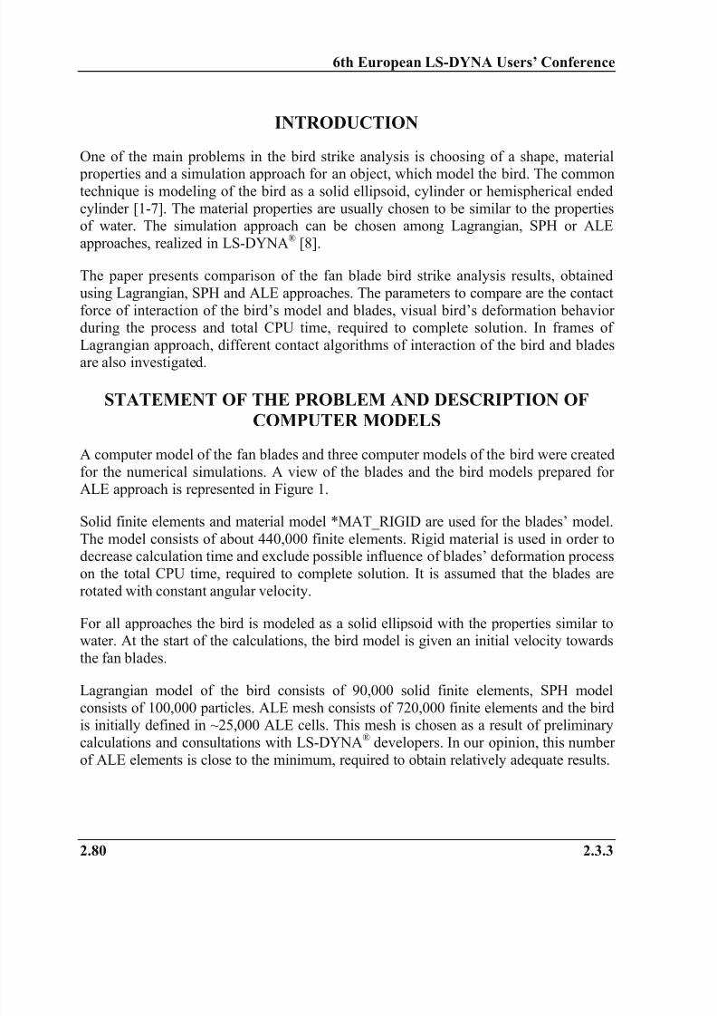
A computer model of the fan blades and three computer models of the bird were created
for the numerical simulations. A view of the blades and the bird models prepared forALE approach is represented in Figure 1.
Solid finite elements and material model *MAT_RIGID are used for the blades’ model.
The model consists of about 440,000 finite elements. Rigid material is used in order todecrease calculation time and exclude possible influence of blades’ deformation process
on the total CPU time, required to complete solution. It is assumed that the blades are
rotated with constant angular velocity.
For all approaches the bird is modeled as a solid ellipsoid with the properties similar towater. At the start of the calculations, the bird model is given an initial velocity towards
the fan blades.
Lagrangian model of the bird consists of 90,000 solid finite elements, SPH model
consists of 100,000 particles. ALE mesh consists of 720,000 finite elements and the birdis initially defined in ~25,000 ALE cells. This mesh is chosen as a result of preliminary
calculations and consultations with LS-DYNA® developers. In our opinion, this number
of ALE elements is close to the minimum, required to obtain relatively adequate results.
8/10/2019 Fan Blade Bird Strike Analysis Using Lagrangian,
http://slidepdf.com/reader/full/fan-blade-bird-strike-analysis-using-lagrangian 3/10
6th European LS-DYNA Users’ Conference
2.3.3 2.81
Figure 1: Computer model (ALE approach)
RESULTS OF LAGRANGIAN CALCULATIONS
In frames of Lagrangian approach, different contact algorithms of the interaction of the bird and blades are investigated:
Calculation Lagr1 – CONTACT_NODES_TO_SURFACE;
Calculation Lagr2 – CONTACT_ERODING_SURFACE_TO_SURFACE;
Calculation Lagr3 – a combination of CONTACT_NODES_TO_SURFACE and
CONTACT_ERODING_SURFACE_TO_SURFACE.
RESULTS OF CALCULATION LAGR1
In this calculation the contact between the bird and blades is modeled using
NODES_TO_SURFACE contact algorithm. All the nodes of the bird model are used as
the slave set and all the external segments of the blades – as the master set. Thistechnique is allowed nodes to be active in contact even after surrounding elements fail.
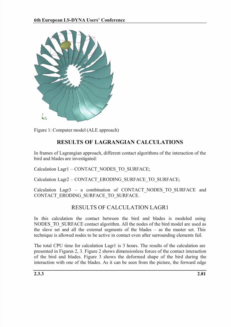
The total CPU time for calculation Lagr1 is 3 hours. The results of the calculation are
presented in Figures 2, 3. Figure 2 shows dimensionless forces of the contact interactionof the bird and blades. Figure 3 shows the deformed shape of the bird during the
interaction with one of the blades. As it can be seen from the picture, the forward edge
8/10/2019 Fan Blade Bird Strike Analysis Using Lagrangian,
http://slidepdf.com/reader/full/fan-blade-bird-strike-analysis-using-lagrangian 4/10
6th European LS-DYNA Users’ Conference
2.82 2.3.3
of the blade penetrates into the bird’s material. This situation appears because the bird is
modeled in the contact by nodes, but not by segments. This allows the blade to penetrate
through the middles of bird’s elements.
Figure 2: Forces of the contact interaction ofthe bird and blades (Lagr1)
Figure 3: Interaction of the bird with oneof the blades (Lagr1)
RESULTS OF CALCULATION LAGR2
In this case the contact between the bird and blades is modeled usingERODING_SURFACE_TO_SURFACE contact algorithm. All the external segments of
the bird model are used as the slave set and all the external segments of the blades – asthe master set. This technique helps to avoid penetration of the blades into the bird’s
material.
The total CPU time for calculation Lagr2 is 3 hours. Figure 4 shows dimensionlessforces of the contact interaction of the bird and blades. As it can be seen from the
picture, all the forces are much less then ones in calculation Lagr1. The cause of this is
that eroding nodes are not active in the contact after surrounding elements fail. Thisleads to underestimation of the contact forces.
RESULTS OF CALCULATION LAGR3
In this calculation the contact between bird and blades is modeled using thecombination of ERODING_SURFACE_TO_SURFACE and NODES_TO_SURFACE
contact algorithms. The forces of the contact interaction are determined usingFORCE_TRANSDUCER_PENALTY algorithm. This technique is both allowed nodes
to be active in the contact even after surrounding elements fail and helps to avoid
penetration of the blades into the bird’s material.

8/10/2019 Fan Blade Bird Strike Analysis Using Lagrangian,
http://slidepdf.com/reader/full/fan-blade-bird-strike-analysis-using-lagrangian 5/10
6th European LS-DYNA Users’ Conference
2.3.3 2.83
Figure 4: Forces of the contact interaction
of the bird and blades (Lagr2)
Figure 5: Forces of the contact interaction
of bird and blades (Lagr3)
The total CPU time for calculation Lagr3 is 5 hours. The results of the calculation are
presented in Figures 5, 6. Figure 5 shows dimensionless forces of the contact interactionof the bird and blades. As it can be seen form the picture, all the forces are quite close to
ones, obtained in calculation Lagr1. Figure 6 shows sequential views of the interactionof the bird and blades. The analysis of the pictures shows that there is no penetration of
the blades into the bird’s material and all the eroding nodes stay active in the contact.
Figure 6: Sequential views of the interaction of the bird and blades (Lagr3)
8/10/2019 Fan Blade Bird Strike Analysis Using Lagrangian,
http://slidepdf.com/reader/full/fan-blade-bird-strike-analysis-using-lagrangian 6/10
6th European LS-DYNA Users’ Conference
2.84 2.3.3
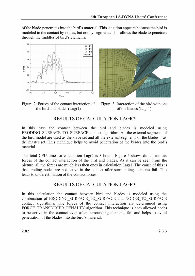
RESULTS OF SPH CALCULATION
In SPH calculation the contact between the bird and blades is based on NODES_TO_SURFACE contact algorithm, the same as in the calculation Lagr1.
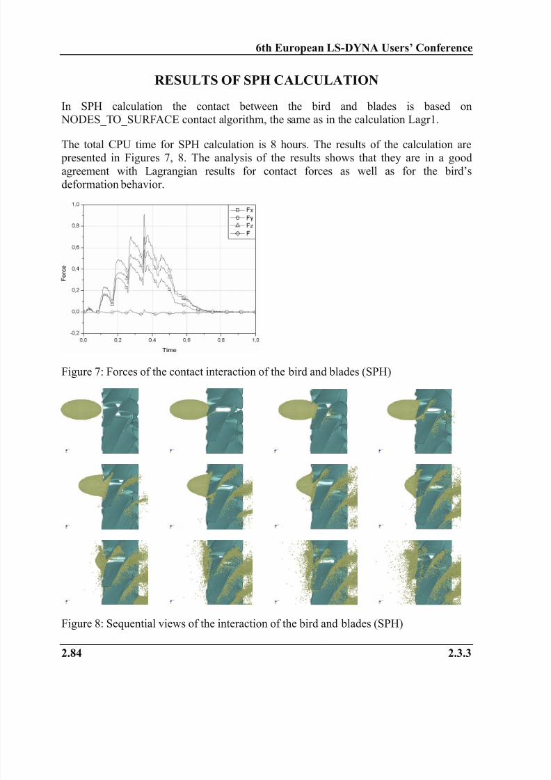
The total CPU time for SPH calculation is 8 hours. The results of the calculation are presented in Figures 7, 8. The analysis of the results shows that they are in a good
agreement with Lagrangian results for contact forces as well as for the bird’s
deformation behavior.
Figure 7: Forces of the contact interaction of the bird and blades (SPH)
Figure 8: Sequential views of the interaction of the bird and blades (SPH)
8/10/2019 Fan Blade Bird Strike Analysis Using Lagrangian,
http://slidepdf.com/reader/full/fan-blade-bird-strike-analysis-using-lagrangian 7/10
6th European LS-DYNA Users’ Conference
2.3.3 2.85
RESULTS OF ALE CALCULATIONS
Two variants of modeling of the interaction of the bird and blades are investigated:
Calculation ALE1 – the interaction of the bird with whole surface of the blade isconsidered;
Calculation ALE2 – the interaction of the bird with only one of the side surfaces of the
blade is considered.
RESULTS OF CALCULATION ALE1
CONSTRAINED_LAGRANGE_IN_SOLID algorithm is used to simulate the contact between the bird and blades. All the external segments of the blades are used as the
slave set.
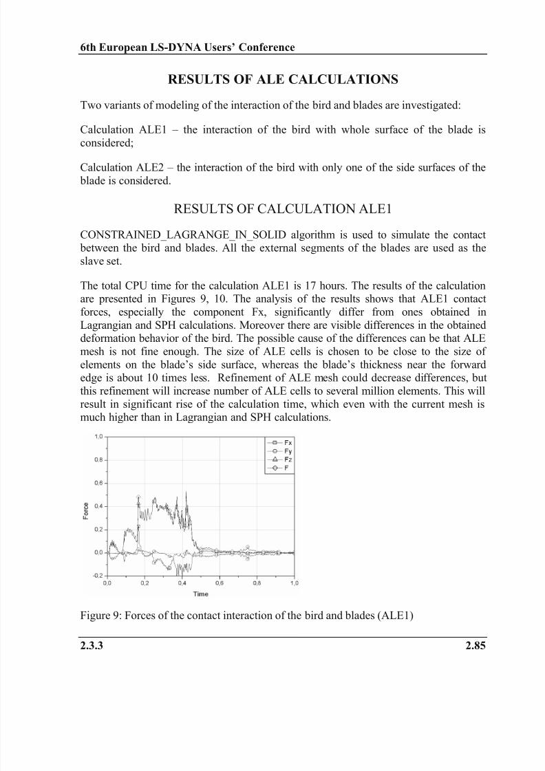
The total CPU time for the calculation ALE1 is 17 hours. The results of the calculationare presented in Figures 9, 10. The analysis of the results shows that ALE1 contact
forces, especially the component Fx, significantly differ from ones obtained in
Lagrangian and SPH calculations. Moreover there are visible differences in the obtaineddeformation behavior of the bird. The possible cause of the differences can be that ALE
mesh is not fine enough. The size of ALE cells is chosen to be close to the size of
elements on the blade’s side surface, whereas the blade’s thickness near the forwardedge is about 10 times less. Refinement of ALE mesh could decrease differences, but
this refinement will increase number of ALE cells to several million elements. This will
result in significant rise of the calculation time, which even with the current mesh ismuch higher than in Lagrangian and SPH calculations.
Figure 9: Forces of the contact interaction of the bird and blades (ALE1)
8/10/2019 Fan Blade Bird Strike Analysis Using Lagrangian,
http://slidepdf.com/reader/full/fan-blade-bird-strike-analysis-using-lagrangian 8/10
6th European LS-DYNA Users’ Conference
2.86 2.3.3
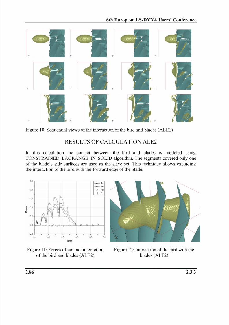
Figure 10: Sequential views of the interaction of the bird and blades (ALE1)
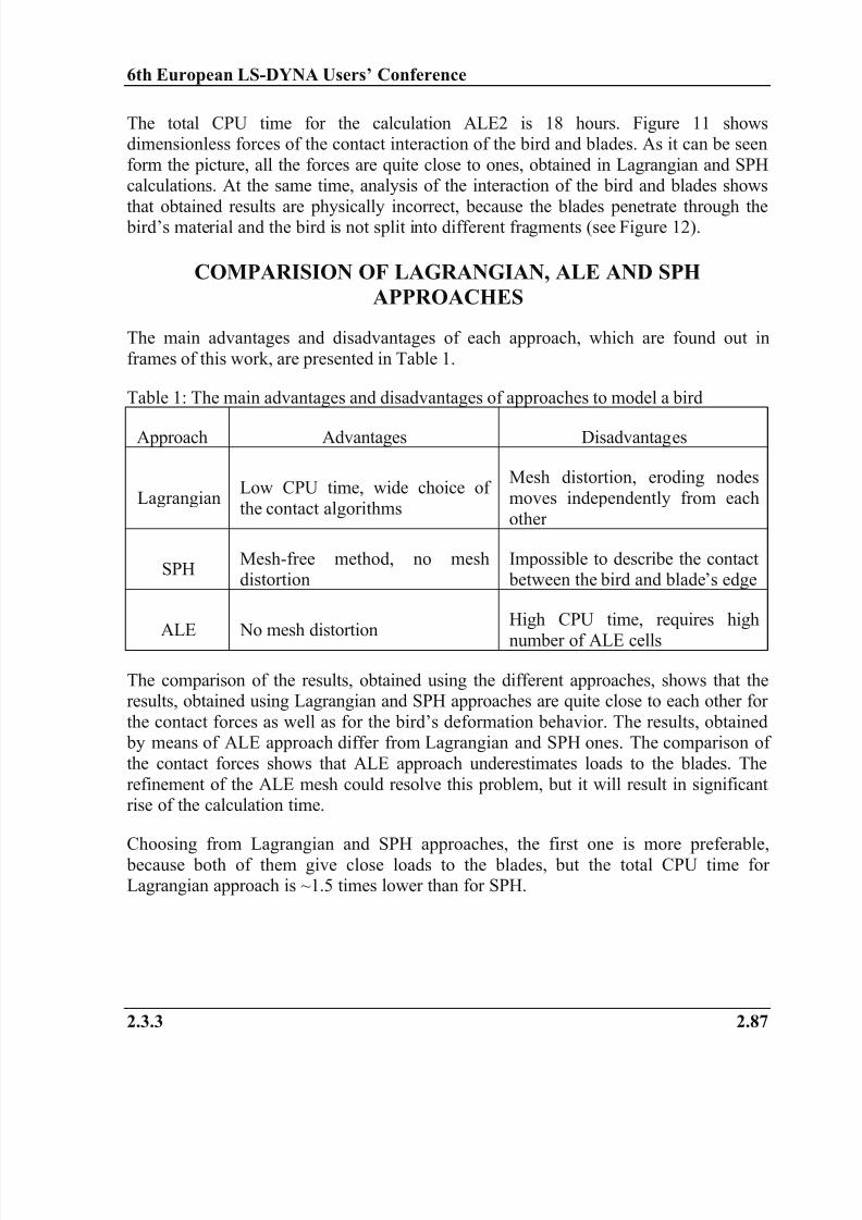
RESULTS OF CALCULATION ALE2
In this calculation the contact between the bird and blades is modeled usingCONSTRAINED_LAGRANGE_IN_SOLID algorithm. The segments covered only one
of the blade’s side surfaces are used as the slave set. This technique allows excluding
the interaction of the bird with the forward edge of the blade.
Figure 11: Forces of contact interaction
of the bird and blades (ALE2)
Figure 12: Interaction of the bird with the
blades (ALE2)
8/10/2019 Fan Blade Bird Strike Analysis Using Lagrangian,
http://slidepdf.com/reader/full/fan-blade-bird-strike-analysis-using-lagrangian 9/10
6th European LS-DYNA Users’ Conference
2.3.3 2.87
The total CPU time for the calculation ALE2 is 18 hours. Figure 11 showsdimensionless forces of the contact interaction of the bird and blades. As it can be seen
form the picture, all the forces are quite close to ones, obtained in Lagrangian and SPHcalculations. At the same time, analysis of the interaction of the bird and blades shows
that obtained results are physically incorrect, because the blades penetrate through the bird’s material and the bird is not split into different fragments (see Figure 12).
COMPARISION OF LAGRANGIAN, ALE AND SPH
APPROACHES
The main advantages and disadvantages of each approach, which are found out in
frames of this work, are presented in Table 1.
Table 1: The main advantages and disadvantages of approaches to model a bird
Approach Advantages Disadvantages
LagrangianLow CPU time, wide choice of
the contact algorithms
Mesh distortion, eroding nodes
moves independently from each
other
SPHMesh-free method, no meshdistortion
Impossible to describe the contact between the bird and blade’s edge
ALE No mesh distortionHigh CPU time, requires high
number of ALE cells
The comparison of the results, obtained using the different approaches, shows that theresults, obtained using Lagrangian and SPH approaches are quite close to each other for
the contact forces as well as for the bird’s deformation behavior. The results, obtained by means of ALE approach differ from Lagrangian and SPH ones. The comparison of
the contact forces shows that ALE approach underestimates loads to the blades. The
refinement of the ALE mesh could resolve this problem, but it will result in significantrise of the calculation time.
Choosing from Lagrangian and SPH approaches, the first one is more preferable,
because both of them give close loads to the blades, but the total CPU time forLagrangian approach is ~1.5 times lower than for SPH.
8/10/2019 Fan Blade Bird Strike Analysis Using Lagrangian,
http://slidepdf.com/reader/full/fan-blade-bird-strike-analysis-using-lagrangian 10/10
6th European LS-DYNA Users’ Conference
2.88 2.3.3
SUMMARY AND CONCLUSIONS
The calculations of the fan blades bird strike problem were carried out using Lagrangain,SPH and ALE approaches to model the bird. The analysis of the obtained results allows
finding out the main advantages and disadvantages of every approach. Basing on theanalysis it can be concluded that Lagrangian approach is currently more preferable for
such problems.
ACKNOWLEDGEMENTS
The authors thank Dr. Arthur Shapiro, LSTC, for constant support of Russian LS-DYNA® users and Dr. Ian Do, LSTC, for help in tuning of the ALE bird model.
REFERENCES
1. T.J. Vasco “Fan Blade Bird-Strike Analysis and Design”, 6th International LS-
DYNA Users Conference, Dearborn, Michigan, 2000.
2. M. Souli, L. Olovsson, I. Do “ALE and Fluid-Structure Interaction Capabilities
in LS-DYNA”, 7th International LS-DYNA Users Conference, Dearborn,
Michigan, 2002.
3. S. Kukanov, D. Roschikhmarov, F. Mantovani “Bird Strike on Composite Inletof a Jet Engine”, FEA information newsletter, May 2005.
4.
S.C. McCallum, C. Constantinou “The Influence of Bird-Shape in Bird-StrikeAnalysis”, 5
th European LS-DYNA Users Conference, Birmingham, 2005.
5. M. Anghileri, L.-M L. Castelletti, F. Invernizzi, M. Mascheroni “Birdstrike
onto the Composite Intake of a Turbofan Engine”, 5th European LS-DYNA
Users Conference, Birmingham, 2005.
6. C.-H. Tho, M.R. Smith “Bird Strike Simulation for BA609 Spinner and RotorControls”, 9th International LS-DYNA® Users Conference, Dearborn, Michigan,
2006.
7.
L. Iannucci, M. Donadon “Bird Strike Modeling Using a New Woven GlassFailure Model”, 9
th International LS-DYNA
® Users Conference, Dearborn,
Michigan, 2006.
8. LS-DYNA® Keyword User's Manual Version 971, Livermore Software
Technology Corporation, Livermore, 2006.