Embed Size (px)
Citation preview
Fan Coil (FCU) Application Guide VTR8000 Series Room Controllers
Application Guide
ControlPerformanceEnergy savingsBetter building management
2
© 2
013
Vic
onic
s Te
chno
logi
es In
c. A
ll rig
hts
rese
rved
.
Viconics Technologies Inc. I Small Building Systems I 9245 Langelier Blvd. Saint-Leonard, Quebec, Canada, H1P 3K9 I +1 514 321 5660 I www.viconics.com028-6047-00 June 2013
Application Guide VTR8000 Fan Coil Controller
TAble oF ConTenTs
Product & application selector 4VTR8300 and SCs | Fan coil terminal equipment controllers 5Cost-saving, energy-saving applications 6VT8000 network ready communication adapters 8VTR8300A5000 - VC3500E5000: Heating/cooling: 4-pipe fan coil unit with 3-speed fan, 2-position valves with wireless door switch 8VTR8350A5000 -VC3404E5000: Cooling and electric heat: 2-pipe fan coil unit with 3-speed fan, dehumidification, 2-position valves 10VTR8300A5000 - VC3504E5000: Heating/cooling with changeover sensor: 2-pipe fan coil unit with 3-speed fan and wirelesss window switch 12VTR8350A5000 - VC3400E5000: Cooling and electric heat: 2-pipe fan coil unit with 3-speed fan and dehumidification, 2-position valves 14VTR8300A5500 - VC3514E5000: Heating/cooling: 2-pipe fan coil unit with 3-speed fan and fresh air damper, 2-position valves 16VTR8300A5000 -VC3500E5000 -VC3300E5000: Heating/cooling: 4-pipe fan coil unit with 3-speed fan, 2-position valves with slave relay pack 18VTR8300A5000 - VC3504E5000: Cooling and electric heat: 2-pipe fan coil unit with 3-speed fan, 2-position valves with wired window switch 20VTR8300A5000 - VC3500E5000: Heating/cooling: 4-pipe fan coil unit with 3-speed fan, 2-position valves with wired door switch 22Appendix A - Passive infra-red (PIR) motion detector cover specifications 25Appendix B - option network wiring if communicating models are used 26Appendix C - controllers’ occupancy sequence of operation schematic 26Appendix D - SED Series - wireless door & window switch 27Appendix E - VTR8300 controller & VC3000 relay pack 29Dimensions of VTR8300 controller 31Specifications 32
3
© 2
013
Vic
onic
s Te
chno
logi
es In
c. A
ll rig
hts
rese
rved
.
Viconics Technologies Inc. I Small Building Systems I 9245 Langelier Blvd. Saint-Leonard, Quebec, Canada, H1P 3K9 I +1 514 321 5660 I www.viconics.com028-6047-00 June 2013
Application Guide VTR8000 Fan Coil Controller
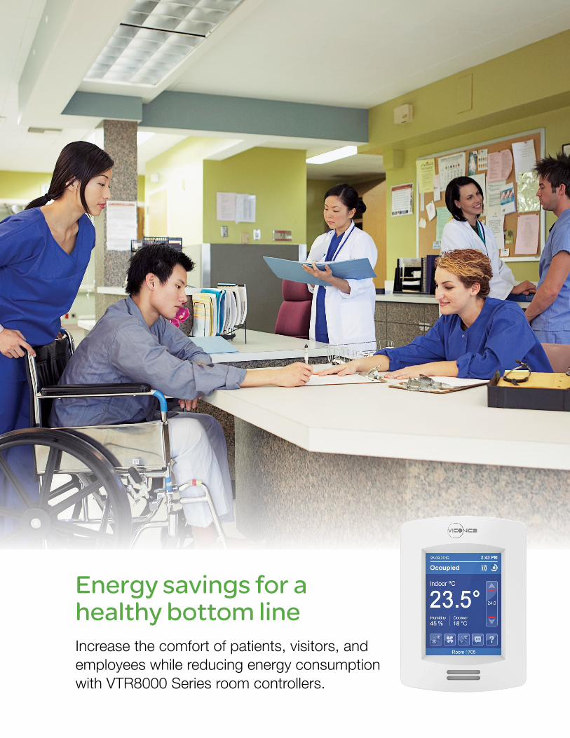
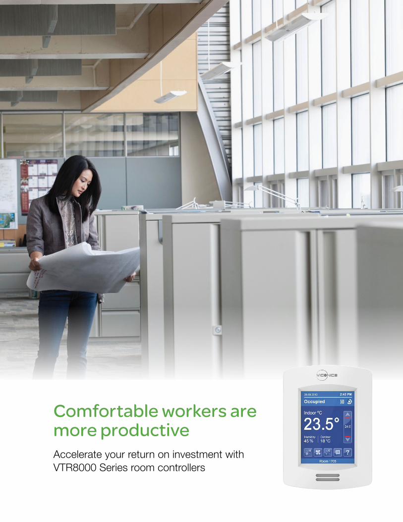
Increase the comfort of patients, visitors, andemployees while reducing energy consumptionwith VTR8000 Series room controllers.
energy savings for a healthy bottom line
4 5
© 2
013
Vic
onic
s Te
chno
logi
es In
c. A
ll rig
hts
rese
rved
.
Viconics Technologies Inc. I Small Building Systems I 9245 Langelier Blvd. Saint-Leonard, Quebec, Canada, H1P 3K9 I +1 514 321 5660 I www.viconics.com028-6047-00 June 2013
Application Guide VTR8000 Fan Coil Controller Application Guide VTR8000 Fan Coil Controller
© 2
013
Vic
onic
s Te
chno
logi
es In
c. A
ll rig
hts
rese
rved
.
Viconics Technologies Inc. I Small Building Systems I 9245 Langelier Blvd. Saint-Leonard, Quebec, Canada, H1P 3K9 I +1 514 321 5660 I www.viconics.com028-6047-00 June 2013
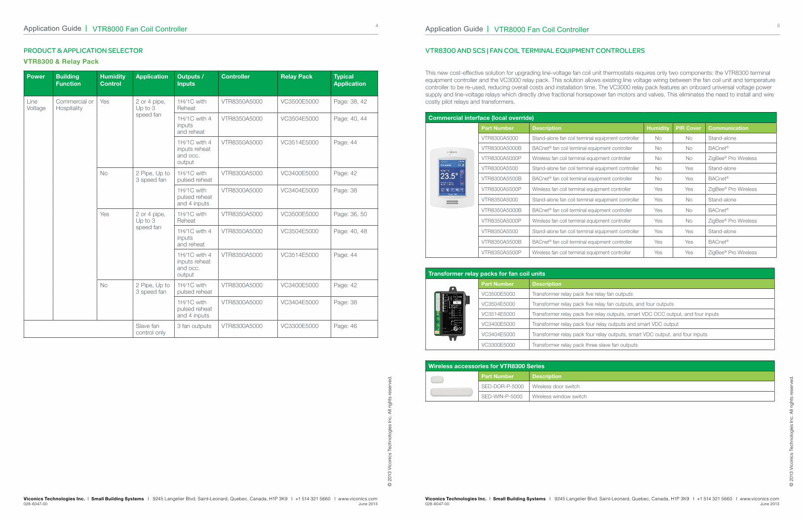
ProdUCT & APPliCATion seleCTorVTR8300 & Relay Pack
This new cost-effective solution for upgrading line-voltage fan coil unit thermostats requires only two components: the VTR8300 terminal equipment controller and the VC3000 relay pack. This solution allows existing line voltage wiring between the fan coil unit and temperature controller to be re-used, reducing overall costs and installation time. The VC3000 relay pack features an onboard universal voltage power supply and line-voltage relays which directly drive fractional horsepower fan motors and valves. This eliminates the need to install and wire costly pilot relays and transformers.
VTr8300 And sCs | FAn Coil TerminAl eqUiPmenT ConTrollers
Power Building Function
Humidity Control
Application Outputs / Inputs
Controller Relay Pack Typical Application
Line Voltage
Commercial orHospitality
Yes 2 or 4 pipe, Up to 3 speed fan
1H/1C with Reheat
VTR8350A5000 VC3500E5000 Page: 38, 42
1H/1C with 4 inputs and reheat
VTR8350A5000 VC3504E5000 Page: 40, 44
1H/1C with 4 inputs reheat and occ. output
VTR8350A5000 VC3514E5000 Page: 44
No 2 Pipe, Up to 3 speed fan
1H/1C with pulsed reheat
VTR8300A5000 VC3400E5000 Page: 42
1H/1C with pulsed reheat and 4 inputs
VTR8300A5000 VC3404E5000 Page: 38
Yes 2 or 4 pipe, Up to 3 speed fan
1H/1C with Reheat
VTR8350A5000 VC3500E5000 Page: 36, 50
1H/1C with 4 inputs and reheat
VTR8350A5000 VC3504E5000 Page: 40, 48
1H/1C with 4 inputs reheat and occ. output
VTR8350A5000 VC3514E5000 Page: 44
No 2 Pipe, Up to 3 speed fan
1H/1C with pulsed reheat
VTR8300A5000 VC3400E5000 Page: 42
1H/1C with pulsed reheat and 4 inputs
VTR8300A5000 VC3404E5000 Page: 38
Slave fan control only
3 fan outputs VTR8300A5000 VC3300E5000 Page: 46
Commercial interface (local override)
Power Part Number Description Humidity PIR Cover Communication
VTR8300A5000 Stand-alone fan coil terminal equipment controller No No Stand-alone
VTR8300A5000B BACnet® fan coil terminal equipment controller No No BACnet®
VTR8300A5000P Wireless fan coil terminal equipment controller No No ZigBee® Pro Wireless
VTR8300A5500 Stand-alone fan coil terminal equipment controller No Yes Stand-alone
VTR8300A5500B BACnet® fan coil terminal equipment controller No Yes BACnet®
VTR8300A5500P Wireless fan coil terminal equipment controller Yes Yes ZigBee® Pro Wireless
VTR8350A5000 Stand-alone fan coil terminal equipment controller Yes No Stand-alone
VTR8350A5000B BACnet® fan coil terminal equipment controller Yes No BACnet®
VTR8350A5000P Wireless fan coil terminal equipment controller Yes No ZigBee® Pro Wireless
VTR8350A5500 Stand-alone fan coil terminal equipment controller Yes Yes Stand-alone
VTR8350A5500B BACnet® fan coil terminal equipment controller Yes Yes BACnet®
VTR8350A5500P Wireless fan coil terminal equipment controller Yes Yes ZigBee® Pro Wireless
Transformer relay packs for fan coil units
Power Part Number Description
VC3500E5000 Transformer relay pack five relay fan outputs
VC3504E5000 Transformer relay pack five relay fan outputs, and four outputs
VC3514E5000 Transformer relay pack five relay outputs, smart VDC OCC output, and four inputs
VC3400E5000 Transformer relay pack four relay outputs and smart VDC output
VC3404E5000 Transformer relay pack four relay outputs, smart VDC output, and four inputs
VC3300E5000 Transformer relay pack three slave fan outputs
Wireless accessories for VTR8300 Series
Power Part Number Description
SED-DOR-P-5000 Wireless door switch
SED-WIN-P-5000 Wireless window switch
6
© 2
013
Vic
onic
s Te
chno
logi
es In
c. A
ll rig
hts
rese
rved
.
Viconics Technologies Inc. I Small Building Systems I 9245 Langelier Blvd. Saint-Leonard, Quebec, Canada, H1P 3K9 I +1 514 321 5660 I www.viconics.com028-6047-00 June 2013
Application Guide VTR8000 Fan Coil Controller
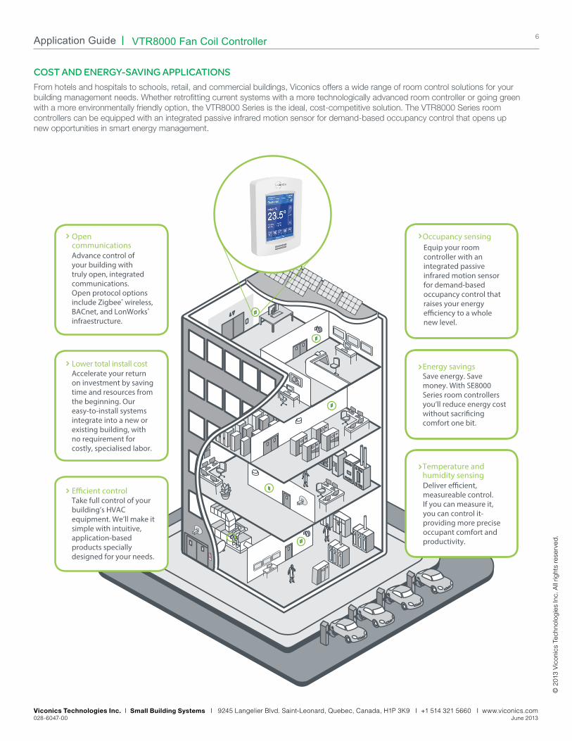
Advance control of your building with truly open, integrated communications.Open protocol options include Zigbee® wireless, BACnet, and LonWorks® infraestructure.
Accelerate your return on investment by saving time and resources from the beginning. Our easy-to-install systems integrate into a new or existing building, with no requirement for costly, specialised labor.
Take full control of your building’s HVAC equipment. We’ll make it simple with intuitive, application-based products specially designed for your needs.
Equip your room controller with an integrated passive infrared motion sensor for demand-based occupancy control that raises your energy e�ciency to a whole new level.
Save energy. Save money. With SE8000 Series room controllers you’ll reduce energy cost without sacri�cing comfort one bit.
Deliver e�cient, measureable control. If you can measure it, you can control it- providing more precise occupant comfort and productivity.
Occupancy sensing
Energy savingsLower total install cost
E�cient control
Opencommunications
Temperature and humidity sensing
CosT And enerGy-sAVinG APPliCATions From hotels and hospitals to schools, retail, and commercial buildings, Viconics offers a wide range of room control solutions for your building management needs. Whether retrofitting current systems with a more technologically advanced room controller or going green with a more environmentally friendly option, the VTR8000 Series is the ideal, cost-competitive solution. The VTR8000 Series room controllers can be equipped with an integrated passive infrared motion sensor for demand-based occupancy control that opens up new opportunities in smart energy management.
7
© 2
013
Vic
onic
s Te
chno
logi
es In
c. A
ll rig
hts
rese
rved
.
Viconics Technologies Inc. I Small Building Systems I 9245 Langelier Blvd. Saint-Leonard, Quebec, Canada, H1P 3K9 I +1 514 321 5660 I www.viconics.com028-6047-00 June 2013
Application Guide VTR8000 Fan Coil Controller
Accelerate your return on investment withVTR8000 Series room controllers
Comfortable workers aremore productive
8 9
© 2
013
Vic
onic
s Te
chno
logi
es In
c. A
ll rig
hts
rese
rved
.
Viconics Technologies Inc. I Small Building Systems I 9245 Langelier Blvd. Saint-Leonard, Quebec, Canada, H1P 3K9 I +1 514 321 5660 I www.viconics.com028-6047-00 June 2013
Application Guide VTR8000 Fan Coil Controller Application Guide VTR8000 Fan Coil Controller
© 2
013
Vic
onic
s Te
chno
logi
es In
c. A
ll rig
hts
rese
rved
.
Viconics Technologies Inc. I Small Building Systems I 9245 Langelier Blvd. Saint-Leonard, Quebec, Canada, H1P 3K9 I +1 514 321 5660 I www.viconics.com028-6047-00 June 2013
Configuration parameter name
Configuration settings
Password 0 is factory set, range is: 0-9999BI1 DoorBI2 NoneRUI1 NoneRBI2 NoneAutoMode ONC or F As per user. Default value = °FRH disp OFFPulsed Heating OFFPipe No 4.0Seq. Operat 2 = Cooling / Heating 4 pipes Fan Menu 2Deh. lockout ONDehumidify As per user. Default value = 50%. Range = 30% to 95%Deh. hyster As per user. Default value = 5%. Range = 2% to 20%Deh. max cool As per user. Default value = 100%. Range = 20% to 100%Standby time 0.5 hours is factory set, range is: 0.0 to 24.0 hours in 0.5hr incrementsUnocc. time 0.0 hours is factory set, range is: 0.0 to 24.0 hours in 0.5hr incrementsStandby heat 69 °F is factory set, range is: 40 to 90 °F ( 4.5 to 32.0 °C )Standby cool 78 °F is factory set, range is: 54 to 100 °F ( 12.0 to 37.5 °C )Unocc heat SP As per user. Default value = 62 °F ( 17 °C ). Range = 40 to 90 °F ( 4.5 to 32.0 °C )Unocc cool SP As per user. Default value = 80 °F ( 27 °C ). Range = 54 to 100 °F ( 12 to 37.5 °C )Max heating As per user. Default value = 90 °F ( 32 °C ). Range = 40 to 90 °F ( 4.5 to 32.0 °C )Max cooling As per user. Default value = 54 °F ( 12 °C ). Range = 54 to 100 °F ( 12 to 37.5 °C )Prop. band 3 °F is factory set, range is: 2 to 10 °F ( 0.6 to 5.6 °C )T. Occup. time As per user. Default value 2 hours. Range = 0 to 24 hoursMin. deadband As per user. Default value 2.0 °F ( 1.0 °C ).calibr. temp. 0 °F or °Ccalibr. humid. 0 °F or °CAuto Fan Funct AS or AS ADCooling cph As per user. 4 to 8 CPHHeating cph As per user. 4 to 8 CPHCooling Valve NCHeat Valve NCFan Control ON
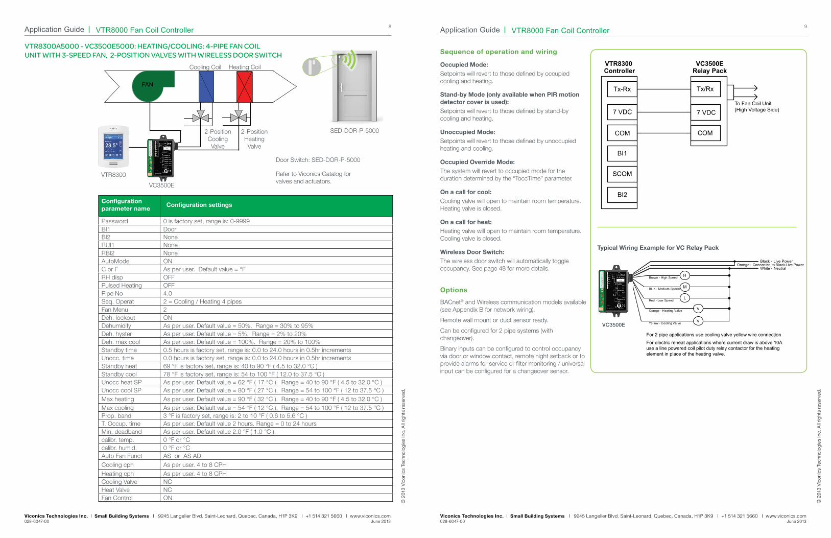
VTr8300A5000 - VC3500e5000: HeATinG/CoolinG: 4-PiPe FAn Coil UniT wiTH 3-sPeed FAn, 2-PosiTion VAlVes wiTH wireless door swiTCH
Door Switch: SED-DOR-P-5000
Refer to Viconics Catalog for valves and actuators.
Sequence of operation and wiring
Occupied Mode:Setpoints will revert to those defined by occupied cooling and heating.
Stand-by Mode (only available when PIR motion detector cover is used):Setpoints will revert to those defined by stand-by cooling and heating.
Unoccupied Mode:Setpoints will revert to those defined by unoccupied heating and cooling.
Occupied Override Mode:The system will revert to occupied mode for the duration determined by the “ToccTime” parameter.
On a call for cool:Cooling valve will open to maintain room temperature. Heating valve is closed.
On a call for heat:Heating valve will open to maintain room temperature. Cooling valve is closed.
Wireless Door Switch:The wireless door switch will automatically toggle occupancy. See page 48 for more details.
Options
BACnet® and Wireless communication models available (see Appendix B for network wiring).
Remote wall mount or duct sensor ready.
Can be configured for 2 pipe systems (with changeover).
Binary inputs can be configured to control occupancy via door or window contact, remote night setback or to provide alarms for service or filter monitoring / universal input can be configured for a changeover sensor.
SED-DOR-P-5000
VTR8300
FAN
2-Position Cooling Valve
2-Position Heating Valve
Cooling Coil Heating Coil
VC3500E
Typical Wiring Example for VC Relay Pack
Black - Live PowerOrange - Connected to Black-Live Power
Brown - High Speed
Blue - Medium Speed
Red - Low Speed
Orange - Heating Valve
Yellow - Cooling Valve
H
M
L
V
V
White - Neutral
For 2 pipe applications use cooling valve yellow wire connectionFor electric reheat applications where current draw is above 10Ause a line powered coil pilot duty relay contactor for the heating element in place of the heating valve.
VC3500E
Tx-Rx
7 VDC
COM
BI1
SCOM
VC3500ERelay Pack
To Fan Coil Unit(High Voltage Side)
VTR8300 Controller
BI2
Tx/Rx
7 VDC
COM
10 11
© 2
013
Vic
onic
s Te
chno
logi
es In
c. A
ll rig
hts
rese
rved
.
Viconics Technologies Inc. I Small Building Systems I 9245 Langelier Blvd. Saint-Leonard, Quebec, Canada, H1P 3K9 I +1 514 321 5660 I www.viconics.com028-6047-00 June 2013
Application Guide VTR8000 Fan Coil Controller Application Guide VTR8000 Fan Coil Controller
© 2
013
Vic
onic
s Te
chno
logi
es In
c. A
ll rig
hts
rese
rved
.
Viconics Technologies Inc. I Small Building Systems I 9245 Langelier Blvd. Saint-Leonard, Quebec, Canada, H1P 3K9 I +1 514 321 5660 I www.viconics.com028-6047-00 June 2013
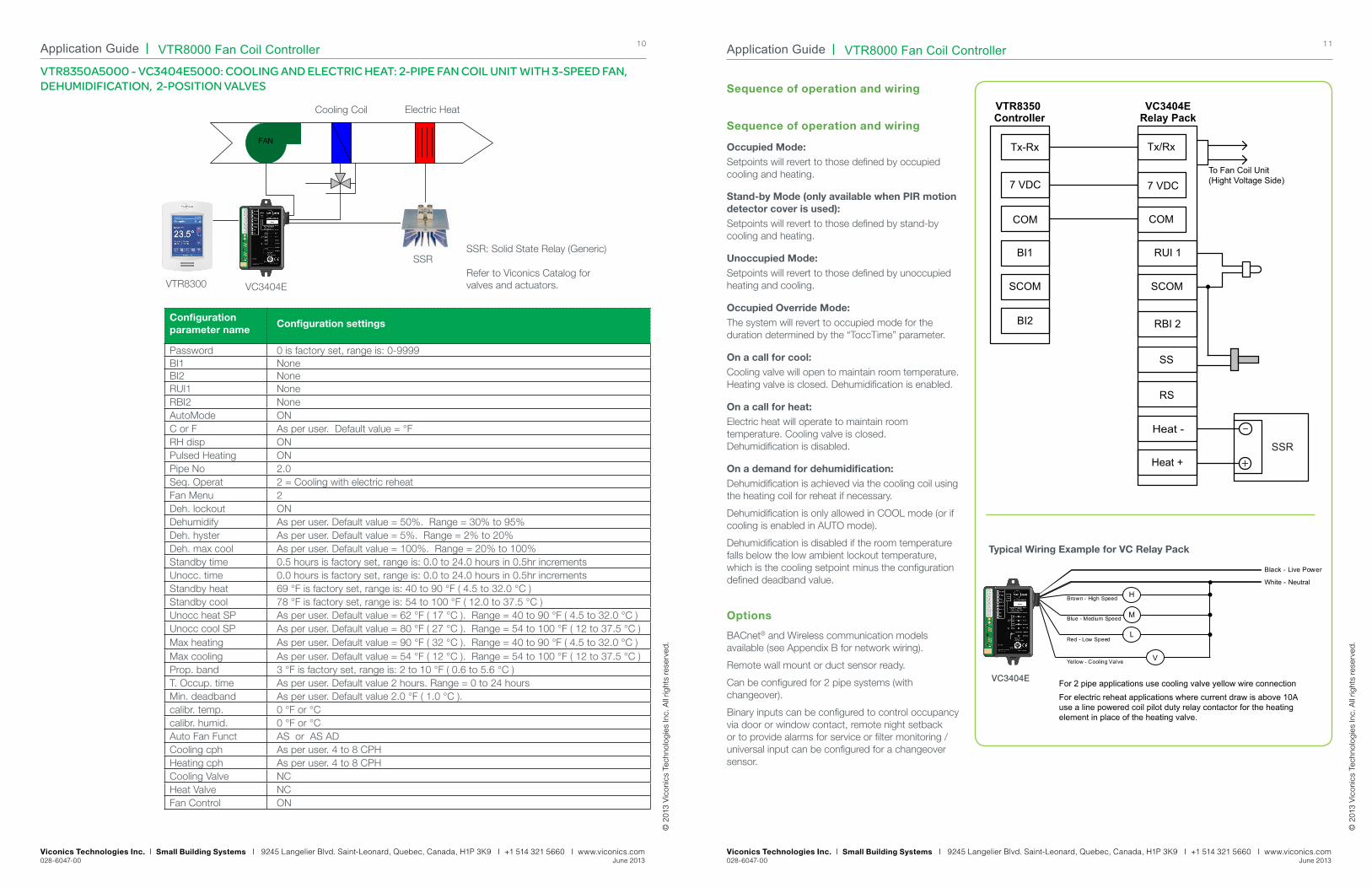
VTr8350A5000 - VC3404e5000: CoolinG And eleCTriC HeAT: 2-PiPe FAn Coil UniT wiTH 3-sPeed FAn, deHUmidiFiCATion, 2-PosiTion VAlVes
SSR: Solid State Relay (Generic)
Refer to Viconics Catalog for valves and actuators.
Cooling Coil
VC3404E
Sequence of operation and wiring
Occupied Mode:Setpoints will revert to those defined by occupied cooling and heating.
Stand-by Mode (only available when PIR motion detector cover is used):Setpoints will revert to those defined by stand-by cooling and heating.
Unoccupied Mode:Setpoints will revert to those defined by unoccupied heating and cooling.
Occupied Override Mode:The system will revert to occupied mode for the duration determined by the “ToccTime” parameter.
On a call for cool:Cooling valve will open to maintain room temperature. Heating valve is closed. Dehumidification is enabled.
On a call for heat:Electric heat will operate to maintain room temperature. Cooling valve is closed. Dehumidification is disabled.
On a demand for dehumidification:Dehumidification is achieved via the cooling coil using the heating coil for reheat if necessary.
Dehumidification is only allowed in COOL mode (or if cooling is enabled in AUTO mode).
Dehumidification is disabled if the room temperature falls below the low ambient lockout temperature, which is the cooling setpoint minus the configuration defined deadband value.
Options
BACnet® and Wireless communication models available (see Appendix B for network wiring).
Remote wall mount or duct sensor ready.
Can be configured for 2 pipe systems (with changeover).
Binary inputs can be configured to control occupancy via door or window contact, remote night setback or to provide alarms for service or filter monitoring / universal input can be configured for a changeover sensor.
Sequence of operation and wiring
FAN
Electric Heat
SSR
Configuration parameter name
Configuration settings
Password 0 is factory set, range is: 0-9999BI1 NoneBI2 NoneRUI1 NoneRBI2 NoneAutoMode ONC or F As per user. Default value = °FRH disp ONPulsed Heating ONPipe No 2.0Seq. Operat 2 = Cooling with electric reheatFan Menu 2Deh. lockout ONDehumidify As per user. Default value = 50%. Range = 30% to 95%Deh. hyster As per user. Default value = 5%. Range = 2% to 20%Deh. max cool As per user. Default value = 100%. Range = 20% to 100%Standby time 0.5 hours is factory set, range is: 0.0 to 24.0 hours in 0.5hr incrementsUnocc. time 0.0 hours is factory set, range is: 0.0 to 24.0 hours in 0.5hr incrementsStandby heat 69 °F is factory set, range is: 40 to 90 °F ( 4.5 to 32.0 °C )Standby cool 78 °F is factory set, range is: 54 to 100 °F ( 12.0 to 37.5 °C )Unocc heat SP As per user. Default value = 62 °F ( 17 °C ). Range = 40 to 90 °F ( 4.5 to 32.0 °C )Unocc cool SP As per user. Default value = 80 °F ( 27 °C ). Range = 54 to 100 °F ( 12 to 37.5 °C )Max heating As per user. Default value = 90 °F ( 32 °C ). Range = 40 to 90 °F ( 4.5 to 32.0 °C )Max cooling As per user. Default value = 54 °F ( 12 °C ). Range = 54 to 100 °F ( 12 to 37.5 °C )Prop. band 3 °F is factory set, range is: 2 to 10 °F ( 0.6 to 5.6 °C )T. Occup. time As per user. Default value 2 hours. Range = 0 to 24 hoursMin. deadband As per user. Default value 2.0 °F ( 1.0 °C ).calibr. temp. 0 °F or °Ccalibr. humid. 0 °F or °CAuto Fan Funct AS or AS ADCooling cph As per user. 4 to 8 CPHHeating cph As per user. 4 to 8 CPHCooling Valve NCHeat Valve NCFan Control ON
VTR8300
Typical Wiring Example for VC Relay Pack
Black - Live Power
Brown - High Speed
Blue - Medium Speed
Red - Low Speed
Yellow - Cooling Valve
H
M
L
V
White - Neutral
For 2 pipe applications use cooling valve yellow wire connectionFor electric reheat applications where current draw is above 10Ause a line powered coil pilot duty relay contactor for the heating element in place of the heating valve.
VC3404E
Tx-Rx
7 VDC
COM
BI1
SCOM
To Fan Coil Unit(Hight Voltage Side)
BI2
Tx/Rx
7 VDC
COM
RUI 1
SCOM
RBI 2
SS
RS
Heat -
Heat +SSR
VC3404ERelay Pack
VTR8350 Controller
12 13
© 2
013
Vic
onic
s Te
chno
logi
es In
c. A
ll rig
hts
rese
rved
.
Viconics Technologies Inc. I Small Building Systems I 9245 Langelier Blvd. Saint-Leonard, Quebec, Canada, H1P 3K9 I +1 514 321 5660 I www.viconics.com028-6047-00 June 2013
Application Guide VTR8000 Fan Coil Controller Application Guide VTR8000 Fan Coil Controller
© 2
013
Vic
onic
s Te
chno
logi
es In
c. A
ll rig
hts
rese
rved
.
Viconics Technologies Inc. I Small Building Systems I 9245 Langelier Blvd. Saint-Leonard, Quebec, Canada, H1P 3K9 I +1 514 321 5660 I www.viconics.com028-6047-00 June 2013
Heating/Cooling Coil
VC3504EVTR8300
FAN
Supply Sensor
C/O Sensor
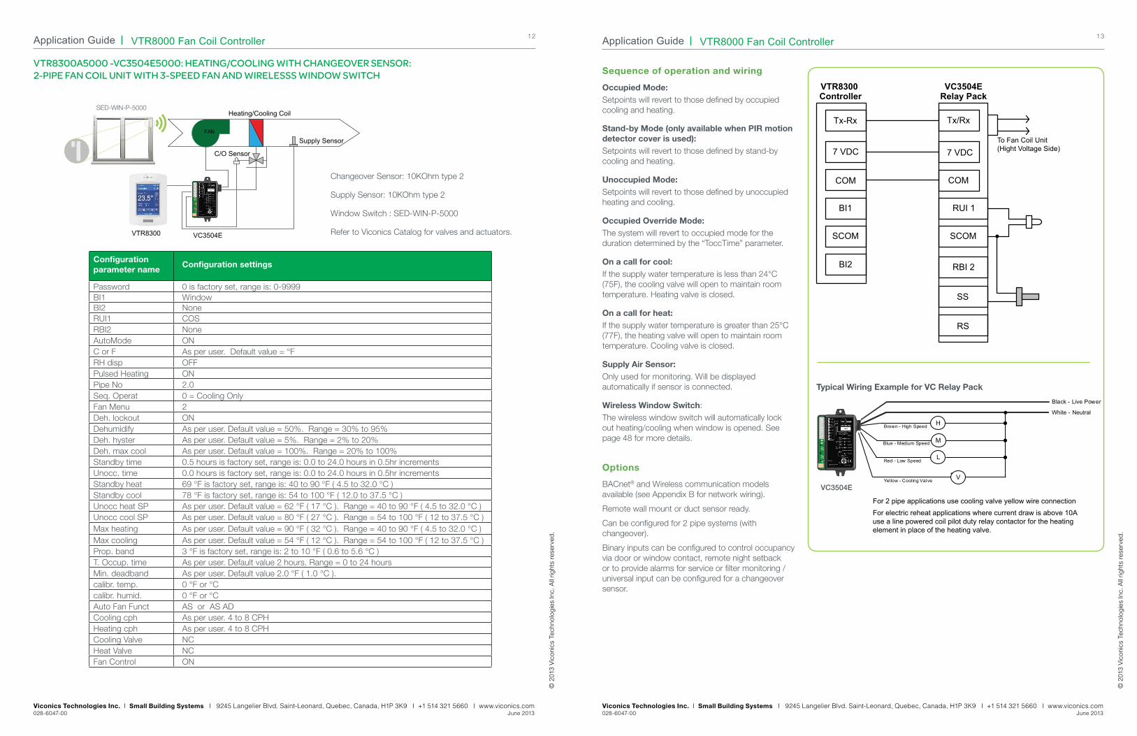
VTr8300A5000 -VC3504e5000: HeATinG/CoolinG wiTH CHAnGeoVer sensor: 2-PiPe FAn Coil UniT wiTH 3-sPeed FAn And wirelesss window swiTCH
Configuration parameter name
Configuration settings
Password 0 is factory set, range is: 0-9999BI1 WindowBI2 NoneRUI1 COSRBI2 NoneAutoMode ONC or F As per user. Default value = °FRH disp OFFPulsed Heating ONPipe No 2.0Seq. Operat 0 = Cooling Only Fan Menu 2Deh. lockout ONDehumidify As per user. Default value = 50%. Range = 30% to 95%Deh. hyster As per user. Default value = 5%. Range = 2% to 20%Deh. max cool As per user. Default value = 100%. Range = 20% to 100%Standby time 0.5 hours is factory set, range is: 0.0 to 24.0 hours in 0.5hr incrementsUnocc. time 0.0 hours is factory set, range is: 0.0 to 24.0 hours in 0.5hr incrementsStandby heat 69 °F is factory set, range is: 40 to 90 °F ( 4.5 to 32.0 °C )Standby cool 78 °F is factory set, range is: 54 to 100 °F ( 12.0 to 37.5 °C )Unocc heat SP As per user. Default value = 62 °F ( 17 °C ). Range = 40 to 90 °F ( 4.5 to 32.0 °C )Unocc cool SP As per user. Default value = 80 °F ( 27 °C ). Range = 54 to 100 °F ( 12 to 37.5 °C )Max heating As per user. Default value = 90 °F ( 32 °C ). Range = 40 to 90 °F ( 4.5 to 32.0 °C )Max cooling As per user. Default value = 54 °F ( 12 °C ). Range = 54 to 100 °F ( 12 to 37.5 °C )Prop. band 3 °F is factory set, range is: 2 to 10 °F ( 0.6 to 5.6 °C )T. Occup. time As per user. Default value 2 hours. Range = 0 to 24 hoursMin. deadband As per user. Default value 2.0 °F ( 1.0 °C ).calibr. temp. 0 °F or °Ccalibr. humid. 0 °F or °CAuto Fan Funct AS or AS ADCooling cph As per user. 4 to 8 CPHHeating cph As per user. 4 to 8 CPHCooling Valve NCHeat Valve NCFan Control ON
Changeover Sensor: 10KOhm type 2
Supply Sensor: 10KOhm type 2
Window Switch : SED-WIN-P-5000
Refer to Viconics Catalog for valves and actuators.
SED-WIN-P-5000
Sequence of operation and wiring
Occupied Mode:Setpoints will revert to those defined by occupied cooling and heating.
Stand-by Mode (only available when PIR motion detector cover is used):Setpoints will revert to those defined by stand-by cooling and heating.
Unoccupied Mode:Setpoints will revert to those defined by unoccupied heating and cooling.
Occupied Override Mode:The system will revert to occupied mode for the duration determined by the “ToccTime” parameter.
On a call for cool:If the supply water temperature is less than 24°C (75F), the cooling valve will open to maintain room temperature. Heating valve is closed.
On a call for heat:If the supply water temperature is greater than 25°C (77F), the heating valve will open to maintain room temperature. Cooling valve is closed.
Supply Air Sensor:Only used for monitoring. Will be displayed automatically if sensor is connected.
Wireless Window Switch:The wireless window switch will automatically lock out heating/cooling when window is opened. See page 48 for more details.
Options
BACnet® and Wireless communication models available (see Appendix B for network wiring).
Remote wall mount or duct sensor ready.
Can be configured for 2 pipe systems (with changeover).
Binary inputs can be configured to control occupancy via door or window contact, remote night setback or to provide alarms for service or filter monitoring / universal input can be configured for a changeover sensor.
Typical Wiring Example for VC Relay Pack
Black - Live Power
Brown - High Speed
Blue - Medium Speed
Red - Low Speed
Yellow - Cooling Valve
H
M
L
V
White - Neutral
For 2 pipe applications use cooling valve yellow wire connectionFor electric reheat applications where current draw is above 10Ause a line powered coil pilot duty relay contactor for the heatingelement in place of the heating valve.
VC3504E
Tx-Rx
7 VDC
COM
BI1
SCOM
To Fan Coil Unit(Hight Voltage Side)
BI2
Tx/Rx
7 VDC
COM
RUI 1
SCOM
RBI 2
SS
RS
VC3504ERelay Pack
VTR8300 Controller
14 15
© 2
013
Vic
onic
s Te
chno
logi
es In
c. A
ll rig
hts
rese
rved
.
Viconics Technologies Inc. I Small Building Systems I 9245 Langelier Blvd. Saint-Leonard, Quebec, Canada, H1P 3K9 I +1 514 321 5660 I www.viconics.com028-6047-00 June 2013
Application Guide VTR8000 Fan Coil Controller Application Guide VTR8000 Fan Coil Controller
© 2
013
Vic
onic
s Te
chno
logi
es In
c. A
ll rig
hts
rese
rved
.
Viconics Technologies Inc. I Small Building Systems I 9245 Langelier Blvd. Saint-Leonard, Quebec, Canada, H1P 3K9 I +1 514 321 5660 I www.viconics.com028-6047-00 June 2013
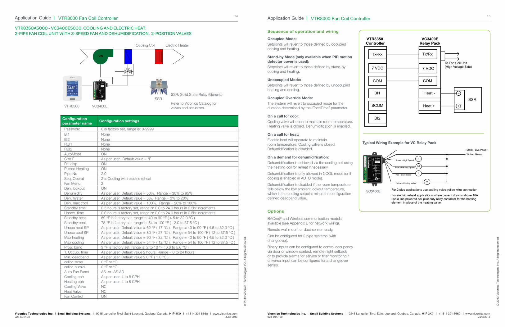
VTr8350A5000 - VC3400e5000: CoolinG And eleCTriC HeAT: 2-PiPe FAn Coil UniT wiTH 3-sPeed FAn And deHUmidiFiCATion, 2-PosiTion VAlVes
SSR: Solid State Relay (Generic)
Refer to Viconics Catalog for valves and actuators.
Cooling Coil Electric Heater
VC3400E
FAN
SSR
Configuration parameter name
Configuration settings
Password 0 is factory set, range is: 0-9999BI1 NoneBI2 NoneRUI1 NoneRBI2 NoneAutoMode ONC or F As per user. Default value = °FRH disp ONPulsed Heating ONPipe No 2.0Seq. Operat 2 = Cooling with electric reheatFan Menu 2Deh. lockout ONDehumidify As per user. Default value = 50%. Range = 30% to 95%Deh. hyster As per user. Default value = 5%. Range = 2% to 20%Deh. max cool As per user. Default value = 100%. Range = 20% to 100%Standby time 0.5 hours is factory set, range is: 0.0 to 24.0 hours in 0.5hr incrementsUnocc. time 0.0 hours is factory set, range is: 0.0 to 24.0 hours in 0.5hr incrementsStandby heat 69 °F is factory set, range is: 40 to 90 °F ( 4.5 to 32.0 °C )Standby cool 78 °F is factory set, range is: 54 to 100 °F ( 12.0 to 37.5 °C )Unocc heat SP As per user. Default value = 62 °F ( 17 °C ). Range = 40 to 90 °F ( 4.5 to 32.0 °C )Unocc cool SP As per user. Default value = 80 °F ( 27 °C ). Range = 54 to 100 °F ( 12 to 37.5 °C )Max heating As per user. Default value = 90 °F ( 32 °C ). Range = 40 to 90 °F ( 4.5 to 32.0 °C )Max cooling As per user. Default value = 54 °F ( 12 °C ). Range = 54 to 100 °F ( 12 to 37.5 °C )Prop. band 3 °F is factory set, range is: 2 to 10 °F ( 0.6 to 5.6 °C )T. Occup. time As per user. Default value 2 hours. Range = 0 to 24 hoursMin. deadband As per user. Default value 2.0 °F ( 1.0 °C ).calibr. temp. 0 °F or °Ccalibr. humid. 0 °F or °CAuto Fan Funct AS or AS ADCooling cph As per user. 4 to 8 CPHHeating cph As per user. 4 to 8 CPHCooling Valve NCHeat Valve NCFan Control ON
VTR8300
Sequence of operation and wiring
Occupied Mode:Setpoints will revert to those defined by occupied cooling and heating.
Stand-by Mode (only available when PIR motion detector cover is used):Setpoints will revert to those defined by stand-by cooling and heating.
Unoccupied Mode:Setpoints will revert to those defined by unoccupied heating and cooling.
Occupied Override Mode:The system will revert to occupied mode for the duration determined by the “ToccTime” parameter.
On a call for cool:Cooling valve will open to maintain room temperature. Heating valve is closed. Dehumidification is enabled.
On a call for heat:Electric heat will opearate to maintain room temperature. Cooling valve is closed. Dehumidification is disabled.
On a demand for dehumidification:Dehumidification is achieved via the cooling coil using the heating coil for reheat if necessary.
Dehumidification is only allowed in COOL mode (or if cooling is enabled in AUTO mode).
Dehumidification is disabled if the room temperature falls below the low ambient lockout temperature, which is the cooling setpoint minus the configuration defined deadband value.
Options
BACnet® and Wireless communication models available (see Appendix B for network wiring).
Remote wall mount or duct sensor ready.
Can be configured for 2 pipe systems (with changeover).
Binary inputs can be configured to control occupancy via door or window contact, remote night setback or to provide alarms for service or filter monitoring / universal input can be configured for a changeover sensor.
Typical Wiring Example for VC Relay Pack
Black - Live Power
Brown - High Speed
Blue - Medium Speed
Red - Low Speed
Yellow - Cooling Valve
H
M
L
V
White - Neutral
For 2 pipe applications use cooling valve yellow wire connection
For electric reheat applications where current draw is above 10Ause a line powered coil pilot duty relay contactor for the heating element in place of the heating valve.
SC3400E
Tx-Rx
7 VDC
COM
BI1
SCOM
To Fan Coil Unit(High Voltage Side)
BI2
Tx/Rx
7 VDC
COM
Heat -
Heat +SSR
VC3400ERelay Pack
VTR8350 Controller
16 17
© 2
013
Vic
onic
s Te
chno
logi
es In
c. A
ll rig
hts
rese
rved
.
Viconics Technologies Inc. I Small Building Systems I 9245 Langelier Blvd. Saint-Leonard, Quebec, Canada, H1P 3K9 I +1 514 321 5660 I www.viconics.com028-6047-00 June 2013
Application Guide VTR8000 Fan Coil Controller Application Guide VTR8000 Fan Coil Controller
© 2
013
Vic
onic
s Te
chno
logi
es In
c. A
ll rig
hts
rese
rved
.
Viconics Technologies Inc. I Small Building Systems I 9245 Langelier Blvd. Saint-Leonard, Quebec, Canada, H1P 3K9 I +1 514 321 5660 I www.viconics.com028-6047-00 June 2013
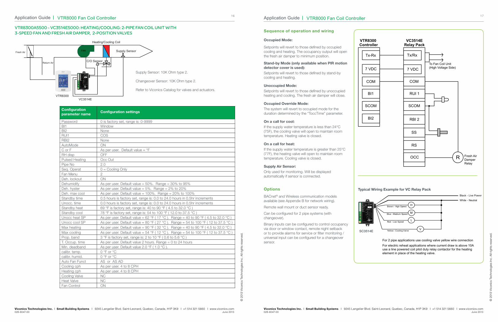
VTr8300A5500 - VC3514e5000: HeATinG/CoolinG: 2-PiPe FAn Coil UniT wiTH 3-sPeed FAn And FresH Air dAmPer, 2-PosiTion VAlVes
Supply Sensor: 10K Ohm type 2.
Changeover Sensor: 10K Ohm type 2.
Refer to Viconics Catalog for valves and actuators.
FAN
VTR8300VC3514E
C/O Sensor
Supply Sensor
Heating/Cooling Coil
Return Air
Fresh Air
Configuration parameter name
Configuration settings
Password 0 is factory set, range is: 0-9999BI1 WindowBI2 NoneRUI1 COSRBI2 NoneAutoMode ONC or F As per user. Default value = °FRH disp OFFPulsed Heating Occ OutPipe No 2.0Seq. Operat 0 = Cooling Only Fan Menu 2Deh. lockout ONDehumidify As per user. Default value = 50%. Range = 30% to 95%Deh. hyster As per user. Default value = 5%. Range = 2% to 20%Deh. max cool As per user. Default value = 100%. Range = 20% to 100%Standby time 0.5 hours is factory set, range is: 0.0 to 24.0 hours in 0.5hr incrementsUnocc. time 0.0 hours is factory set, range is: 0.0 to 24.0 hours in 0.5hr incrementsStandby heat 69 °F is factory set, range is: 40 to 90 °F ( 4.5 to 32.0 °C )Standby cool 78 °F is factory set, range is: 54 to 100 °F ( 12.0 to 37.5 °C )Unocc heat SP As per user. Default value = 62 °F ( 17 °C ). Range = 40 to 90 °F ( 4.5 to 32.0 °C )Unocc cool SP As per user. Default value = 80 °F ( 27 °C ). Range = 54 to 100 °F ( 12 to 37.5 °C )Max heating As per user. Default value = 90 °F ( 32 °C ). Range = 40 to 90 °F ( 4.5 to 32.0 °C )Max cooling As per user. Default value = 54 °F ( 12 °C ). Range = 54 to 100 °F ( 12 to 37.5 °C )Prop. band 3 °F is factory set, range is: 2 to 10 °F ( 0.6 to 5.6 °C )T. Occup. time As per user. Default value 2 hours. Range = 0 to 24 hoursMin. deadband As per user. Default value 2.0 °F ( 1.0 °C ).calibr. temp. 0 °F or °Ccalibr. humid. 0 °F or °CAuto Fan Funct AS or AS ADCooling cph As per user. 4 to 8 CPHHeating cph As per user. 4 to 8 CPHCooling Valve NCHeat Valve NCFan Control ON
Sequence of operation and wiring
Occupied Mode:
Setpoints will revert to those defined by occupied cooling and heating. The occupancy output will open the fresh air damper to minimum position.
Stand-by Mode (only available when PIR motion detector cover is used):Setpoints will revert to those defined by stand-by cooling and heating.
Unoccupied Mode:Setpoints will revert to those defined by unoccupied heating and cooling. The fresh air damper will close.
Occupied Override Mode:The system will revert to occupied mode for the duration determined by the “ToccTime” parameter.
On a call for cool:If the supply water temperature is less than 24°C (75F), the cooling valve will open to maintain room temperature. Heating valve is closed.
On a call for heat:If the supply water temperature is greater than 25°C (77F), the heating valve will open to maintain room temperature. Cooling valve is closed.
Supply Air Sensor:Only used for monitoring. Will be displayed automatically if sensor is connected.
Options
BACnet® and Wireless communication models available (see Appendix B for network wiring).
Remote wall mount or duct sensor ready.
Can be configured for 2 pipe systems (with changeover).
Binary inputs can be configured to control occupancy via door or window contact, remote night setback or to provide alarms for service or filter monitoring / universal input can be configured for a changeover sensor.
Typical Wiring Example for VC Relay Pack
Black - Live Power
Brown - High Speed
Blue - Medium Speed
Red - Low Speed
Yellow - Cooling Valve
H
M
L
V
White - Neutral
For 2 pipe applications use cooling valve yellow wire connectionFor electric reheat applications where current draw is above 10Ause a line powered coil pilot duty relay contactor for the heating element in place of the heating valve.
SC3514E
Tx-Rx
7 VDC
COM
BI1
SCOM
To Fan Coil Unit(High Voltage Side)
BI2
Tx/Rx
7 VDC
COM
RUI 1
SCOM
RBI 2
SS
RS
OCC R Fresh Air Damper Relay
VC3514ERelay Pack
VTR8300 Controller
18 19
© 2
013
Vic
onic
s Te
chno
logi
es In
c. A
ll rig
hts
rese
rved
.
Viconics Technologies Inc. I Small Building Systems I 9245 Langelier Blvd. Saint-Leonard, Quebec, Canada, H1P 3K9 I +1 514 321 5660 I www.viconics.com028-6047-00 June 2013
Application Guide VTR8000 Fan Coil Controller Application Guide VTR8000 Fan Coil Controller
© 2
013
Vic
onic
s Te
chno
logi
es In
c. A
ll rig
hts
rese
rved
.
Viconics Technologies Inc. I Small Building Systems I 9245 Langelier Blvd. Saint-Leonard, Quebec, Canada, H1P 3K9 I +1 514 321 5660 I www.viconics.com028-6047-00 June 2013
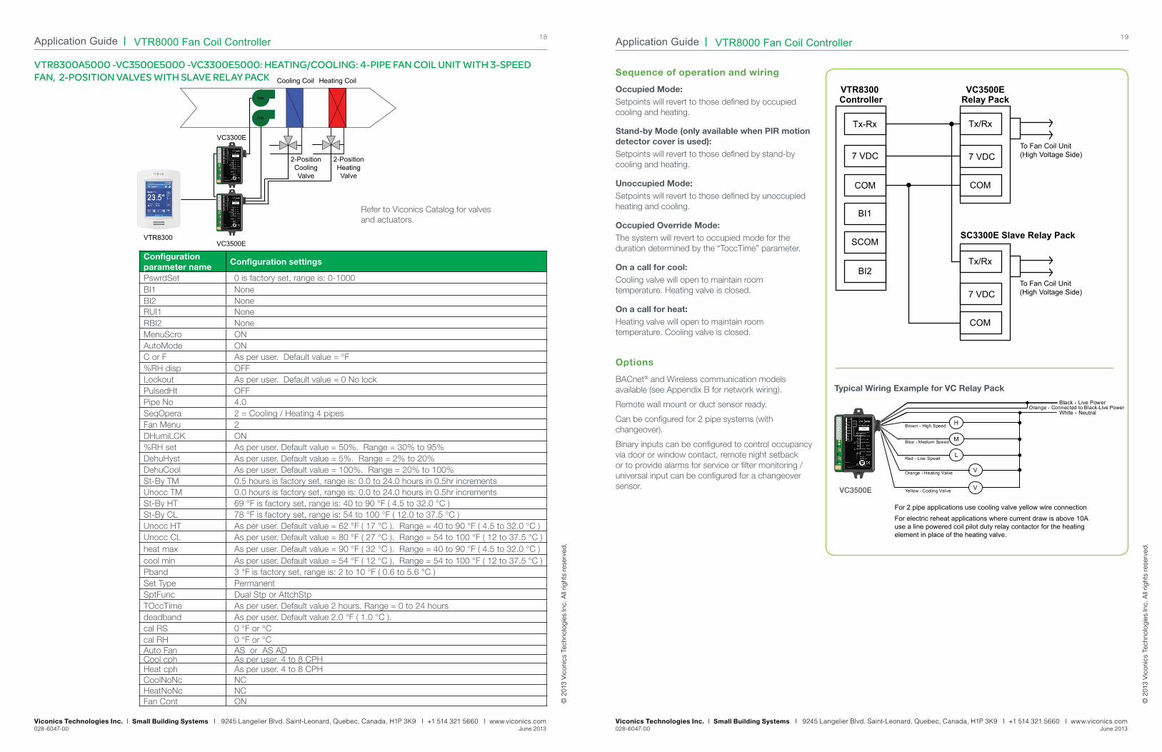
Configuration parameter name
Configuration settings
PswrdSet 0 is factory set, range is: 0-1000BI1 NoneBI2 NoneRUI1 NoneRBI2 NoneMenuScro ONAutoMode ONC or F As per user. Default value = °F%RH disp OFFLockout As per user. Default value = 0 No lockPulsedHt OFFPipe No 4.0SeqOpera 2 = Cooling / Heating 4 pipes Fan Menu 2DHumiLCK ON%RH set As per user. Default value = 50%. Range = 30% to 95%DehuHyst As per user. Default value = 5%. Range = 2% to 20%DehuCool As per user. Default value = 100%. Range = 20% to 100%St-By TM 0.5 hours is factory set, range is: 0.0 to 24.0 hours in 0.5hr incrementsUnocc TM 0.0 hours is factory set, range is: 0.0 to 24.0 hours in 0.5hr incrementsSt-By HT 69 °F is factory set, range is: 40 to 90 °F ( 4.5 to 32.0 °C )St-By CL 78 °F is factory set, range is: 54 to 100 °F ( 12.0 to 37.5 °C )Unocc HT As per user. Default value = 62 °F ( 17 °C ). Range = 40 to 90 °F ( 4.5 to 32.0 °C )Unocc CL As per user. Default value = 80 °F ( 27 °C ). Range = 54 to 100 °F ( 12 to 37.5 °C )heat max As per user. Default value = 90 °F ( 32 °C ). Range = 40 to 90 °F ( 4.5 to 32.0 °C )cool min As per user. Default value = 54 °F ( 12 °C ). Range = 54 to 100 °F ( 12 to 37.5 °C )Pband 3 °F is factory set, range is: 2 to 10 °F ( 0.6 to 5.6 °C )Set Type PermanentSptFunc Dual Stp or AttchStpTOccTime As per user. Default value 2 hours. Range = 0 to 24 hoursdeadband As per user. Default value 2.0 °F ( 1.0 °C ).cal RS 0 °F or °Ccal RH 0 °F or °CAuto Fan AS or AS ADCool cph As per user. 4 to 8 CPHHeat cph As per user. 4 to 8 CPHCoolNoNc NCHeatNoNc NCFan Cont ON
VTr8300A5000 -VC3500e5000 -VC3300e5000: HeATinG/CoolinG: 4-PiPe FAn Coil UniT wiTH 3-sPeed FAn, 2-PosiTion VAlVes wiTH slAVe relAy PACk
Refer to Viconics Catalog for valves and actuators.
VTR8300
FAN
2-Position Cooling Valve
2-Position Heating Valve
Cooling Coil Heating Coil
VC3500E
FAN
VC3300E
Made in Canada
1
2
3PowerSupply
Tx / Rx
7 Vdc
Com
STATUS
BLACK
YELLOW
RED
BLUE
BROWN
COOL
FANLOW
FANMED
FANHIGH
ORANGE
ORANGEHEAT
008-0566
WHITE90-277 Vac - 50/60 Hz1/2HP + 5A Max Comb.Amb. Temp. 50oC
A90-277 Vac10Amb. Temp. 50oC
Max
5AMax
1/2 HPMax
Use copper conductors75oC min. only.
SC3500E5045
Made in Canada
1
2
3PowerSupply
Tx / Rx
7 Vdc
Com
STATUS
BLACK
YELLOW
RED
BLUE
BROWN
9
10
Heat-
Heat+
008-0563
WHITE
COOL
FANLOW
FANMED
FANHIGH
90-277 Vac - 50/60 Hz1/2HP + 5A Max Comb.Amb. Temp. 50oC
Use copper conductors75oC min. only.
5AMax
1/2 HPMax
SC3300E5045
Sequence of operation and wiring
Occupied Mode:Setpoints will revert to those defined by occupied cooling and heating.
Stand-by Mode (only available when PIR motion detector cover is used):Setpoints will revert to those defined by stand-by cooling and heating.
Unoccupied Mode:Setpoints will revert to those defined by unoccupied heating and cooling.
Occupied Override Mode:The system will revert to occupied mode for the duration determined by the “ToccTime” parameter.
On a call for cool:Cooling valve will open to maintain room temperature. Heating valve is closed.
On a call for heat:Heating valve will open to maintain room temperature. Cooling valve is closed.
Options
BACnet® and Wireless communication models available (see Appendix B for network wiring).
Remote wall mount or duct sensor ready.
Can be configured for 2 pipe systems (with changeover).
Binary inputs can be configured to control occupancy via door or window contact, remote night setback or to provide alarms for service or filter monitoring / universal input can be configured for a changeover sensor.
Typical Wiring Example for VC Relay Pack
Black - Live PowerOrange - Connected to Black-Live Power
Brown - High Speed
Blue - Medium Speed
Red - Low Speed
Orange - Heating Valve
Yellow - Cooling Valve
H
M
L
V
V
White - Neutral
For 2 pipe applications use cooling valve yellow wire connectionFor electric reheat applications where current draw is above 10Ause a line powered coil pilot duty relay contactor for the heating element in place of the heating valve.
VC3500E
Tx-Rx
7 VDC
COM
BI1
SCOM
To Fan Coil Unit(High Voltage Side)
BI2
Tx/Rx
7 VDC
COM
SC3300E Slave Relay Pack
To Fan Coil Unit(High Voltage Side)
Tx/Rx
7 VDC
COM
VC3500ERelay Pack
VTR8300 Controller
20 21
© 2
013
Vic
onic
s Te
chno
logi
es In
c. A
ll rig
hts
rese
rved
.
Viconics Technologies Inc. I Small Building Systems I 9245 Langelier Blvd. Saint-Leonard, Quebec, Canada, H1P 3K9 I +1 514 321 5660 I www.viconics.com028-6047-00 June 2013
Application Guide VTR8000 Fan Coil Controller Application Guide VTR8000 Fan Coil Controller
© 2
013
Vic
onic
s Te
chno
logi
es In
c. A
ll rig
hts
rese
rved
.
Viconics Technologies Inc. I Small Building Systems I 9245 Langelier Blvd. Saint-Leonard, Quebec, Canada, H1P 3K9 I +1 514 321 5660 I www.viconics.com028-6047-00 June 2013
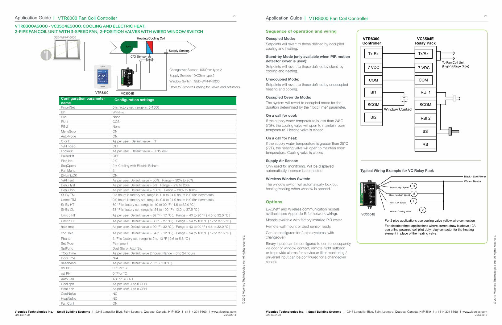
Configuration parameter name
Configuration settings
PswrdSet 0 is factory set, range is: 0-1000
BI1 WindowBI2 NoneRUI1 COS
RBI2 None
MenuScro ON
AutoMode ON
C or F As per user. Default value = °F
%RH disp OFF
Lockout As per user. Default value = 0 No lock
PulsedHt OFF
Pipe No 2.0
SeqOpera 2 = Cooling with Electric Reheat
Fan Menu 2
DHumiLCK ON
%RH set As per user. Default value = 50%. Range = 30% to 95%
DehuHyst As per user. Default value = 5%. Range = 2% to 20%
DehuCool As per user. Default value = 100%. Range = 20% to 100%
St-By TM 0.5 hours is factory set, range is: 0.0 to 24.0 hours in 0.5hr increments
Unocc TM 0.0 hours is factory set, range is: 0.0 to 24.0 hours in 0.5hr increments
St-By HT 69 °F is factory set, range is: 40 to 90 °F ( 4.5 to 32.0 °C )
St-By CL 78 °F is factory set, range is: 54 to 100 °F ( 12.0 to 37.5 °C )
Unocc HT As per user. Default value = 62 °F ( 17 °C ). Range = 40 to 90 °F ( 4.5 to 32.0 °C )
Unocc CL As per user. Default value = 80 °F ( 27 °C ). Range = 54 to 100 °F ( 12 to 37.5 °C )
heat max As per user. Default value = 90 °F ( 32 °C ). Range = 40 to 90 °F ( 4.5 to 32.0 °C )
cool min As per user. Default value = 54 °F ( 12 °C ). Range = 54 to 100 °F ( 12 to 37.5 °C )
Pband 3 °F is factory set, range is: 2 to 10 °F ( 0.6 to 5.6 °C )
Set Type Permanent
SptFunc Dual Stp or AttchStp
TOccTime As per user. Default value 2 hours. Range = 0 to 24 hours
DoorTime N/A
deadband As per user. Default value 2.0 °F ( 1.0 °C ).
cal RS 0 °F or °C
cal RH 0 °F or °C
Auto Fan AS or AS AD
Cool cph As per user. 4 to 8 CPH
Heat cph As per user. 4 to 8 CPH
CoolNoNc NC
HeatNoNc NC
Fan Cont ON
VTr8300A5000 - VC3504e5000: CoolinG And eleCTriC HeAT: 2-PiPe FAn Coil UniT wiTH 3-sPeed FAn, 2-PosiTion VAlVes wiTH wired window swiTCH
Heating/Cooling Coil
VC3504EVTR8300
FAN
Supply Sensor
C/O Sensor
Changeover Sensor: 10KOhm type 2
Supply Sensor: 10KOhm type 2
Window Switch : SED-WIN-P-5000
Refer to Viconics Catalog for valves and actuators.
SED-WIN-P-5000
Sequence of operation and wiring
Occupied Mode:Setpoints will revert to those defined by occupied cooling and heating.
Stand-by Mode (only available when PIR motion detector cover is used):Setpoints will revert to those defined by stand-by cooling and heating.
Unoccupied Mode:Setpoints will revert to those defined by unoccupied heating and cooling.
Occupied Override Mode:The system will revert to occupied mode for the duration determined by the “ToccTime” parameter.
On a call for cool:If the supply water temperature is less than 24°C (75F), the cooling valve will open to maintain room temperature. Heating valve is closed.
On a call for heat:If the supply water temperature is greater than 25°C (77F), the heating valve will open to maintain room temperature. Cooling valve is closed.
Supply Air Sensor:Only used for monitoring. Will be displayed automatically if sensor is connected.
Wireless Window Switch:The window switch will automatically lock out heating/cooling when window is opened.
Options
BACnet® and Wireless communication models available (see Appendix B for network wiring).
Models available with factory installed PIR cover.
Remote wall mount or duct sensor ready.
Can be configured for 2 pipe systems (with changeover).
Binary inputs can be configured to control occupancy via door or window contact, remote night setback or to provide alarms for service or filter monitoring / universal input can be configured for a changeover sensor.
Tx-Rx
7 VDC
COM
BI1
SCOM
BI2
Tx/Rx
7 VDC
COM
RUI 1
SCOM
RBI 2
SS
RS
Window Contact
To Fan Coil Unit(High Voltage Side)
VC3504ERelay Pack
VTR8300 Controller
Black - Live Power
Brown - High Speed
Blue - Medium Speed
Red - Low Speed
Yellow - Cooling Valve
H
M
L
V
White - Neutral
For 2 pipe applications use cooling valve yellow wire connectionFor electric reheat applications where current draw is above 10Ause a line powered coil pilot duty relay contactor for the heatingelement in place of the heating valve.
VC3504E
Typical Wiring Example for VC Relay Pack
22 23
© 2
013
Vic
onic
s Te
chno
logi
es In
c. A
ll rig
hts
rese
rved
.
Viconics Technologies Inc. I Small Building Systems I 9245 Langelier Blvd. Saint-Leonard, Quebec, Canada, H1P 3K9 I +1 514 321 5660 I www.viconics.com028-6047-00 June 2013
Application Guide VTR8000 Fan Coil Controller Application Guide VTR8000 Fan Coil Controller
© 2
013
Vic
onic
s Te
chno
logi
es In
c. A
ll rig
hts
rese
rved
.
Viconics Technologies Inc. I Small Building Systems I 9245 Langelier Blvd. Saint-Leonard, Quebec, Canada, H1P 3K9 I +1 514 321 5660 I www.viconics.com028-6047-00 June 2013
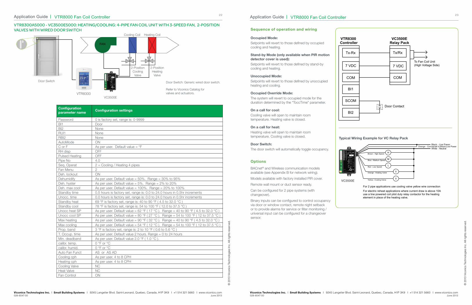
VTr8300A5000 - VC3500e5000: HeATinG/CoolinG: 4-PiPe FAn Coil UniT wiTH 3-sPeed FAn, 2-PosiTion VAlVes wiTH wired door swiTCH
Door Switch: Generic wired door switch.
Refer to Viconics Catalog for valves and actuators.
FAN
2-Position Cooling Valve
2-Position Heating Valve
Cooling Coil Heating Coil
VC3500E
Door Switch
Configuration parameter name
Configuration settings
Password 0 is factory set, range is: 0-9999BI1 DoorBI2 NoneRUI1 NoneRBI2 NoneAutoMode ONC or F As per user. Default value = °FRH disp OFFPulsed Heating OFFPipe No 4.0Seq. Operat 2 = Cooling / Heating 4 pipes Fan Menu 2Deh. lockout ONDehumidify As per user. Default value = 50%. Range = 30% to 95%Deh. hyster As per user. Default value = 5%. Range = 2% to 20%Deh. max cool As per user. Default value = 100%. Range = 20% to 100%Standby time 0.5 hours is factory set, range is: 0.0 to 24.0 hours in 0.5hr incrementsUnocc. time 0.0 hours is factory set, range is: 0.0 to 24.0 hours in 0.5hr incrementsStandby heat 69 °F is factory set, range is: 40 to 90 °F ( 4.5 to 32.0 °C )Standby cool 78 °F is factory set, range is: 54 to 100 °F ( 12.0 to 37.5 °C )Unocc heat SP As per user. Default value = 62 °F ( 17 °C ). Range = 40 to 90 °F ( 4.5 to 32.0 °C )Unocc cool SP As per user. Default value = 80 °F ( 27 °C ). Range = 54 to 100 °F ( 12 to 37.5 °C )Max heating As per user. Default value = 90 °F ( 32 °C ). Range = 40 to 90 °F ( 4.5 to 32.0 °C )Max cooling As per user. Default value = 54 °F ( 12 °C ). Range = 54 to 100 °F ( 12 to 37.5 °C )Prop. band 3 °F is factory set, range is: 2 to 10 °F ( 0.6 to 5.6 °C )T. Occup. time As per user. Default value 2 hours. Range = 0 to 24 hoursMin. deadband As per user. Default value 2.0 °F ( 1.0 °C ).calibr. temp. 0 °F or °Ccalibr. humid. 0 °F or °CAuto Fan Funct AS or AS ADCooling cph As per user. 4 to 8 CPHHeating cph As per user. 4 to 8 CPHCooling Valve NCHeat Valve NCFan Control ON
VTR8300
Sequence of operation and wiring
Occupied Mode:Setpoints will revert to those defined by occupied cooling and heating.
Stand-by Mode (only available when PIR motion detector cover is used):Setpoints will revert to those defined by stand-by cooling and heating.
Unoccupied Mode:Setpoints will revert to those defined by unoccupied heating and cooling.
Occupied Override Mode:The system will revert to occupied mode for the duration determined by the “ToccTime” parameter.
On a call for cool:Cooling valve will open to maintain room temperature. Heating valve is closed.
On a call for heat:Heating valve will open to maintain room temperature. Cooling valve is closed.
Door Switch:The door switch will automatically toggle occupancy.
Options
BACnet® and Wireless communication models available (see Appendix B for network wiring).
Models available with factory installed PIR cover.
Remote wall mount or duct sensor ready.
Can be configured for 2 pipe systems (with changeover).
Binary inputs can be configured to control occupancy via door or window contact, remote night setback or to provide alarms for service or filter monitoring / universal input can be configured for a changeover sensor.
Tx-Rx
7 VDC
COM
BI1
SCOM
BI2
Tx/Rx
7 VDC
COM
Door Contact
To Fan Coil Unit(High Voltage Side)
VC3500ERelay Pack
VTR8300 Controller
Black - Live PowerOrange - Connected to Black-Live Power
Brown - High Speed
Blue - Medium Speed
Red - Low Speed
Orange - Heating Valve
Yellow - Cooling Valve
H
M
L
V
V
White - Neutral
For 2 pipe applications use cooling valve yellow wire connectionFor electric reheat applications where current draw is above 10Ause a line powered coil pilot duty relay contactor for the heating element in place of the heating valve.
VC3500E
Typical Wiring Example for VC Relay Pack
24 25
© 2
013
Vic
onic
s Te
chno
logi
es In
c. A
ll rig
hts
rese
rved
.
Viconics Technologies Inc. I Small Building Systems I 9245 Langelier Blvd. Saint-Leonard, Quebec, Canada, H1P 3K9 I +1 514 321 5660 I www.viconics.com028-6047-00 June 2013
Application Guide VTR8000 Fan Coil Controller Application Guide VTR8000 Fan Coil Controller
© 2
013
Vic
onic
s Te
chno
logi
es In
c. A
ll rig
hts
rese
rved
.
Viconics Technologies Inc. I Small Building Systems I 9245 Langelier Blvd. Saint-Leonard, Quebec, Canada, H1P 3K9 I +1 514 321 5660 I www.viconics.com028-6047-00 June 2013
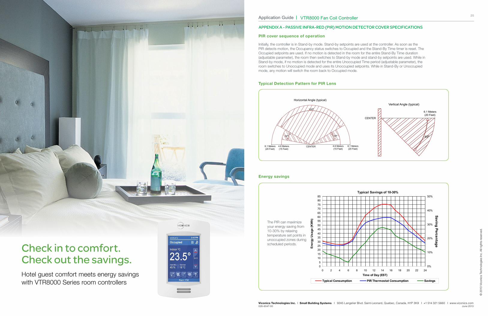
APPendix A - PAssiVe inFrA-red (Pir) moTion deTeCTor CoVer sPeCiFiCATions
Initially, the controller is in Stand-by mode. Stand-by setpoints are used at the controller. As soon as the PIR detects motion, the Occupancy status switches to Occupied and the Stand-By Time timer is reset. The Occupied setpoints are used. If no motion is detected in the room for the entire Stand-By Time duration (adjustable parameter), the room then switches to Stand-by mode and stand-by setpoints are used. While in Stand-by mode, if no motion is detected for the entire Unoccupied Time period (adjustable parameter), the room switches to Unoccupied mode and uses its Unoccupied setpoints. While in Stand-By or Unoccupied mode, any motion will switch the room back to Occupied mode.
PIR cover sequence of operation
Hotel guest comfort meets energy savingswith VTR8000 Series room controllers
Check in to comfort. Check out the savings.
The PIR can maximize your energy saving from 10-30% by relaxing temperature set points in unoccupied zones during scheduled periods.
Typical Savings of 10-30%
05
10152025303540455055606570758085
0 2 4 6 8 10 12 14 16 18 20 22 24
Time of Day (EST)
Ener
gy U
sage
(KW
h)
0%
10%
20%
30%
40%
50%
Saving Percentage
Typical Consumption PIR Thermostat Consumption Savings
Typical Detection Pattern for PIR Lens
Energy savings
Horizontal Angle (typical)
6.1 Meters (20 Feet)
4.6 Meters (15 Feet)
CENTER4.6 Meters (15 Feet)
6.1 Meters (20 Feet)
°120
1515 °°
CENTER
Vertical Angle (typical)
6.1 Meters (20 Feet)
45°
26 27
© 2
013
Vic
onic
s Te
chno
logi
es In
c. A
ll rig
hts
rese
rved
.
Viconics Technologies Inc. I Small Building Systems I 9245 Langelier Blvd. Saint-Leonard, Quebec, Canada, H1P 3K9 I +1 514 321 5660 I www.viconics.com028-6047-00 June 2013
Application Guide VTR8000 Fan Coil Controller Application Guide VTR8000 Fan Coil Controller
© 2
013
Vic
onic
s Te
chno
logi
es In
c. A
ll rig
hts
rese
rved
.
Viconics Technologies Inc. I Small Building Systems I 9245 Langelier Blvd. Saint-Leonard, Quebec, Canada, H1P 3K9 I +1 514 321 5660 I www.viconics.com028-6047-00 June 2013
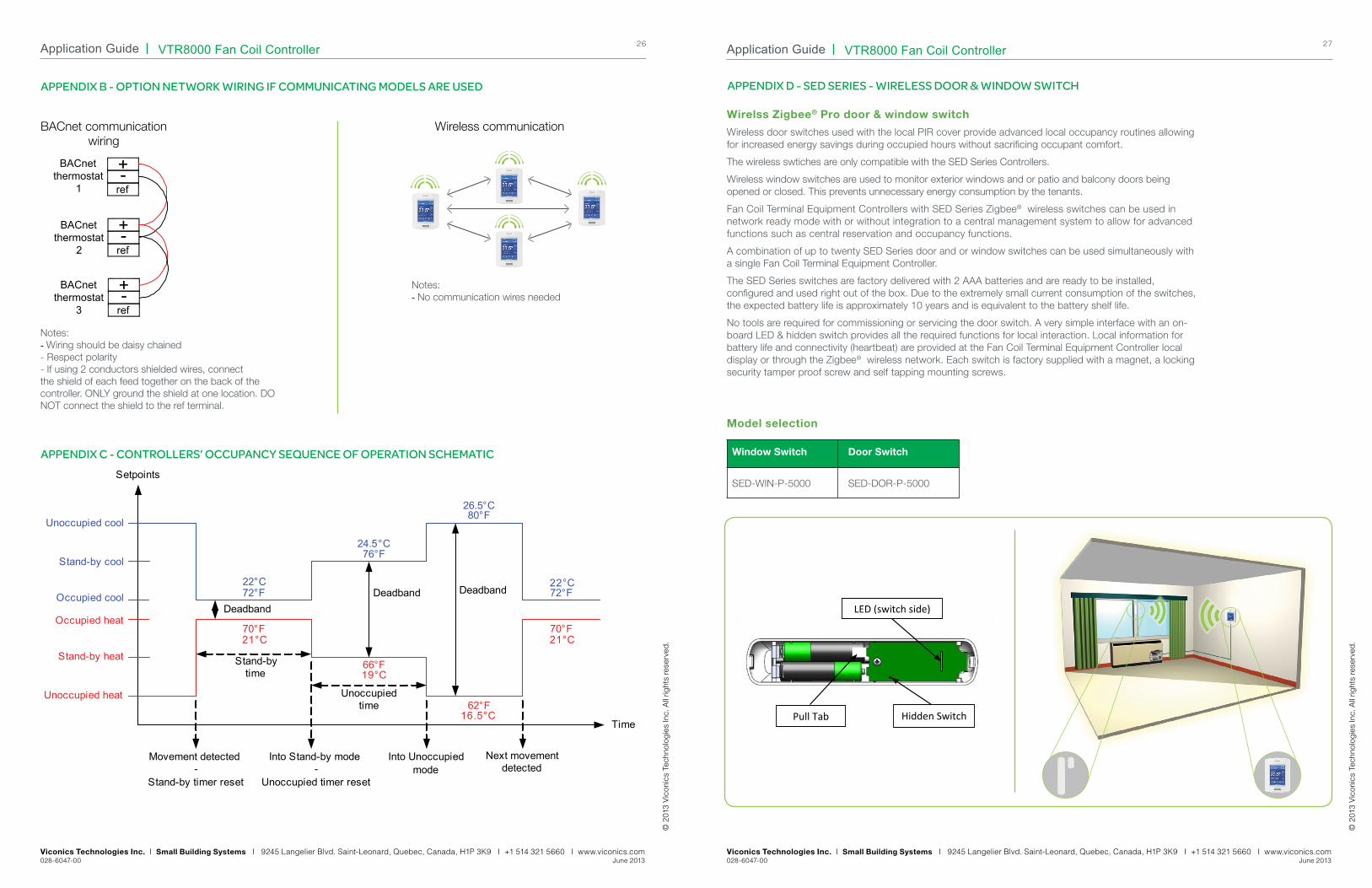
APPendix b - oPTion neTwork wirinG iF CommUniCATinG models Are Used
+-ref
+-ref
+-ref
BACnetthermostat
1
BACnetthermostat
2
BACnetthermostat
3
Notes:- Wiring should be daisy chained- Respect polarity- If using 2 conductors shielded wires, connect the shield of each feed together on the back of the controller. ONLY ground the shield at one location. DO NOT connect the shield to the ref terminal.
Notes:- No communication wires needed
APPendix C - ConTrollers’ oCCUPAnCy seqUenCe oF oPerATion sCHemATiCSetpoints
Time
Unoccupied cool
Occupied cool
Stand-by cool
72°F
76°F
80°F
Movement detected-
Stand-by timer reset
Into Stand-by mode-
Unoccupied timer reset
Stand-bytime
Unoccupiedtime
Into Unoccupiedmode
Next movementdetected
70°F
62°FUnoccupied heat
Occupied heat
Stand-by heat
72°F
66°F
70°F
Deadband Deadband
Deadband
22°C
24.5°C
26.5°C
22°C
21°C 21°C
19°C
16.5°C
BACnet communicationwiring
Wireless communication
APPendix d - sed series - wireless door & window swiTCH
Wirelss Zigbee® Pro door & window switch
Wireless door switches used with the local PIR cover provide advanced local occupancy routines allowing for increased energy savings during occupied hours without sacrificing occupant comfort.
The wireless swtiches are only compatible with the SED Series Controllers.
Wireless window switches are used to monitor exterior windows and or patio and balcony doors being opened or closed. This prevents unnecessary energy consumption by the tenants.
Fan Coil Terminal Equipment Controllers with SED Series Zigbee® wireless switches can be used in network ready mode with or without integration to a central management system to allow for advanced functions such as central reservation and occupancy functions.
A combination of up to twenty SED Series door and or window switches can be used simultaneously with a single Fan Coil Terminal Equipment Controller.
The SED Series switches are factory delivered with 2 AAA batteries and are ready to be installed, configured and used right out of the box. Due to the extremely small current consumption of the switches, the expected battery life is approximately 10 years and is equivalent to the battery shelf life.
No tools are required for commissioning or servicing the door switch. A very simple interface with an on-board LED & hidden switch provides all the required functions for local interaction. Local information for battery life and connectivity (heartbeat) are provided at the Fan Coil Terminal Equipment Controller local display or through the Zigbee® wireless network. Each switch is factory supplied with a magnet, a locking security tamper proof screw and self tapping mounting screws.
Window Switch Door Switch
SED-WIN-P-5000 SED-DOR-P-5000
Model selection
LED (switch side)
Hidden Switch Pull Tab
28 29
© 2
013
Vic
onic
s Te
chno
logi
es In
c. A
ll rig
hts
rese
rved
.
Viconics Technologies Inc. I Small Building Systems I 9245 Langelier Blvd. Saint-Leonard, Quebec, Canada, H1P 3K9 I +1 514 321 5660 I www.viconics.com028-6047-00 June 2013
Application Guide VTR8000 Fan Coil Controller Application Guide VTR8000 Fan Coil Controller
© 2
013
Vic
onic
s Te
chno
logi
es In
c. A
ll rig
hts
rese
rved
.
Viconics Technologies Inc. I Small Building Systems I 9245 Langelier Blvd. Saint-Leonard, Quebec, Canada, H1P 3K9 I +1 514 321 5660 I www.viconics.com028-6047-00 June 2013
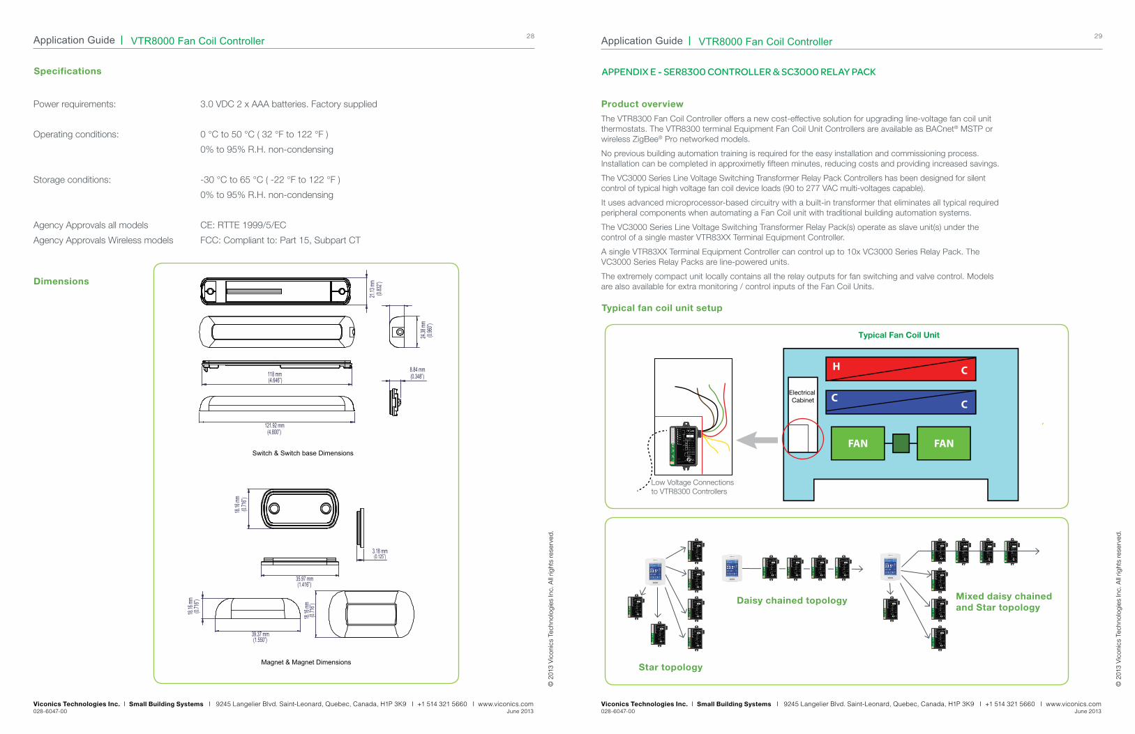
Specifications
Power requirements: 3.0 VDC 2 x AAA batteries. Factory supplied
Operating conditions: 0 °C to 50 °C ( 32 °F to 122 °F )
0% to 95% R.H. non-condensing
Storage conditions: -30 °C to 65 °C ( -22 °F to 122 °F )
0% to 95% R.H. non-condensing
Agency Approvals all models CE: RTTE 1999/5/EC
Agency Approvals Wireless models FCC: Compliant to: Part 15, Subpart CT
Dimensions
(0.71
6”)
(0.125”)
(1.416”)
(0.96
0”)
21.13
mm
(4.646”) (0.348”)(0.
832”)
24.38
mm
118 mm
(4.800”)121.92 mm
8.84 mm
18.16
mm
35.97 mm
3.18 mm
(0.71
6”)18
.16 m
m
(0.71
6”)18
.16 m
m
(1.550”)39.37 mm
Switch & Switch base Dimensions
Magnet & Magnet Dimensions
APPendix e - ser8300 ConTroller & sC3000 relAy PACk
Product overview
The VTR8300 Fan Coil Controller offers a new cost-effective solution for upgrading line-voltage fan coil unit thermostats. The VTR8300 terminal Equipment Fan Coil Unit Controllers are available as BACnet® MSTP or wireless ZigBee® Pro networked models.
No previous building automation training is required for the easy installation and commissioning process. Installation can be completed in approximetly fifteen minutes, reducing costs and providing increased savings.
The VC3000 Series Line Voltage Switching Transformer Relay Pack Controllers has been designed for silent control of typical high voltage fan coil device loads (90 to 277 VAC multi-voltages capable).
It uses advanced microprocessor-based circuitry with a built-in transformer that eliminates all typical required peripheral components when automating a Fan Coil unit with traditional building automation systems.
The VC3000 Series Line Voltage Switching Transformer Relay Pack(s) operate as slave unit(s) under the control of a single master VTR83XX Terminal Equipment Controller.
A single VTR83XX Terminal Equipment Controller can control up to 10x VC3000 Series Relay Pack. The VC3000 Series Relay Packs are line-powered units.
The extremely compact unit locally contains all the relay outputs for fan switching and valve control. Models are also available for extra monitoring / control inputs of the Fan Coil Units.
Typical fan coil unit setup
Star topology
Daisy chained topology Mixed daisy chained and Star topology
H
FAN FAN
C
C
CElectrical Cabinet
Low Voltage Connectionsto SER8300 Controller
Typical Fan Coil Unit
Low Voltage Connectionsto VTR8300 Controllers
30 31
© 2
013
Vic
onic
s Te
chno
logi
es In
c. A
ll rig
hts
rese
rved
.
Viconics Technologies Inc. I Small Building Systems I 9245 Langelier Blvd. Saint-Leonard, Quebec, Canada, H1P 3K9 I +1 514 321 5660 I www.viconics.com028-6047-00 June 2013
Application Guide VTR8000 Fan Coil Controller Application Guide VTR8000 Fan Coil Controller
© 2
013
Vic
onic
s Te
chno
logi
es In
c. A
ll rig
hts
rese
rved
.
Viconics Technologies Inc. I Small Building Systems I 9245 Langelier Blvd. Saint-Leonard, Quebec, Canada, H1P 3K9 I +1 514 321 5660 I www.viconics.com028-6047-00 June 2013
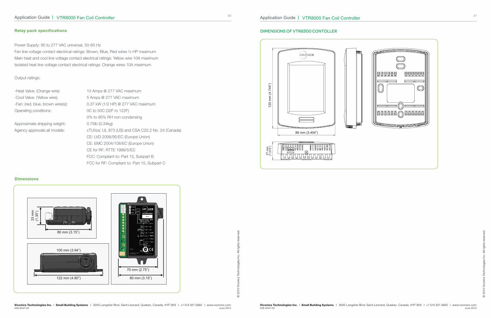
100 mm (3.94”)
80 mm (3.15”)
122 mm (4.80”) 80 mm (3.15”)
70 mm (2.75”)
33 m
m(1
.30”
)
Relay pack specifications
Dimensions
Power Supply: 90 to 277 VAC universal, 50-60 Hz
Fan line voltage contact electrical ratings: Brown, Blue, Red wires ½ HP maximum
Main heat and cool line voltage contact electrical ratings: Yellow wire 10A maximum
Isolated heat line voltage contact electrical ratings: Orange wires 10A maximum
Output ratings:
-Heat Valve: (Orange wire): 10 Amps @ 277 VAC maximum
-Cool Valve: (Yellow wire): 5 Amps @ 277 VAC maximum
-Fan: (red, blue, brown wire(s)): 0.37 kW (1/2 HP) @ 277 VAC maximum
Operating conditions: 0C to 50C (32F ro 122F)
0% to 95% RH non-condensing
Approximate shipping weight: 0.75lb (0.34kg)
Agency approvals all models: cTUVus: UL 873 (US) and CSA C22.2 No. 24 (Canada)
CE: LVD 2006/95/EC (Europe Union)
CE: EMC 2004/108/EC (Europe Union)
CE for RF: RTTE 1999/5/EC
FCC: Compliant to: Part 15, Subpart B
FCC for RF: Compliant to: Part 15, Subpart C
86 mm (3.404”)
120
mm
(4.7
44”)
2
7 m
m
(1.0
72”)
dimensions oF VTr8300 ConToller
32
© 2
013
Vic
onic
s Te
chno
logi
es In
c. A
ll rig
hts
rese
rved
.
Viconics Technologies Inc. I Small Building Systems I 9245 Langelier Blvd. Saint-Leonard, Quebec, Canada, H1P 3K9 I +1 514 321 5660 I www.viconics.com028-6047-00 June 2013
Application Guide VTR8000 Fan Coil Controller
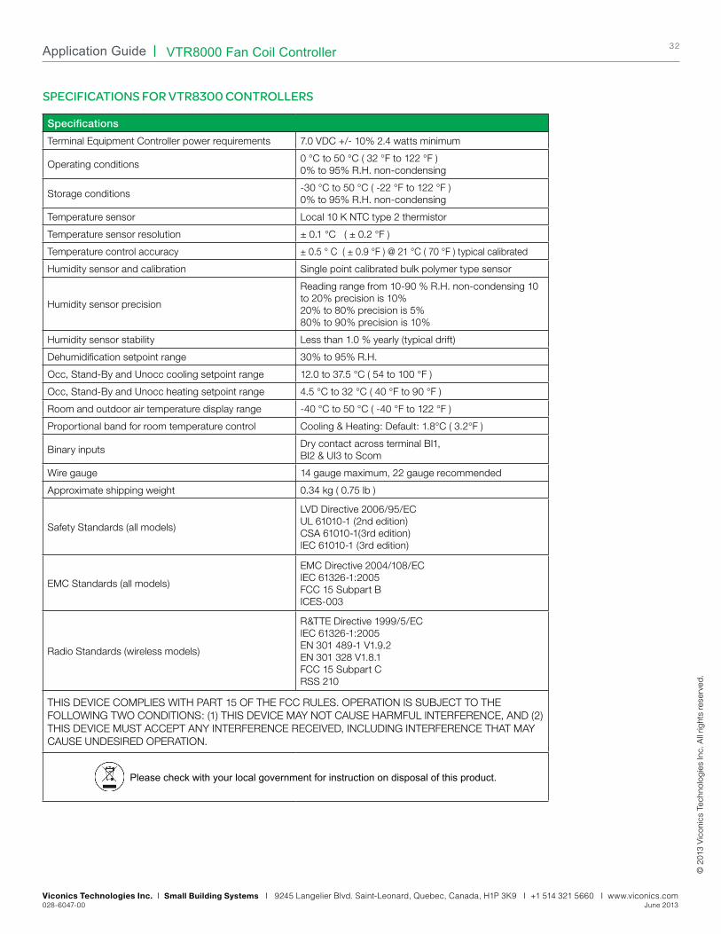
sPeCiFiCATions For VTr8300 ConTrollers
Specifications
Terminal Equipment Controller power requirements 7.0 VDC +/- 10% 2.4 watts minimum
Operating conditions0 °C to 50 °C ( 32 °F to 122 °F ) 0% to 95% R.H. non-condensing
Storage conditions-30 °C to 50 °C ( -22 °F to 122 °F ) 0% to 95% R.H. non-condensing
Temperature sensor Local 10 K NTC type 2 thermistor
Temperature sensor resolution ± 0.1 °C ( ± 0.2 °F )
Temperature control accuracy ± 0.5 ° C ( ± 0.9 °F ) @ 21 °C ( 70 °F ) typical calibrated
Humidity sensor and calibration Single point calibrated bulk polymer type sensor
Humidity sensor precision
Reading range from 10-90 % R.H. non-condensing 10 to 20% precision is 10% 20% to 80% precision is 5% 80% to 90% precision is 10%
Humidity sensor stability Less than 1.0 % yearly (typical drift)
Dehumidification setpoint range 30% to 95% R.H.
Occ, Stand-By and Unocc cooling setpoint range 12.0 to 37.5 °C ( 54 to 100 °F )
Occ, Stand-By and Unocc heating setpoint range 4.5 °C to 32 °C ( 40 °F to 90 °F )
Room and outdoor air temperature display range -40 °C to 50 °C ( -40 °F to 122 °F )
Proportional band for room temperature control Cooling & Heating: Default: 1.8°C ( 3.2°F )
Binary inputsDry contact across terminal BI1, BI2 & UI3 to Scom
Wire gauge 14 gauge maximum, 22 gauge recommended
Approximate shipping weight 0.34 kg ( 0.75 lb )
Safety Standards (all models)
LVD Directive 2006/95/EC UL 61010-1 (2nd edition)CSA 61010-1(3rd edition) IEC 61010-1 (3rd edition)
EMC Standards (all models)
EMC Directive 2004/108/EC IEC 61326-1:2005 FCC 15 Subpart B ICES-003
Radio Standards (wireless models)
R&TTE Directive 1999/5/EC IEC 61326-1:2005 EN 301 489-1 V1.9.2 EN 301 328 V1.8.1 FCC 15 Subpart C RSS 210
THIS DEVICE COMPLIES WITH PART 15 OF THE FCC RULES. OPERATION IS SUBJECT TO THE FOLLOWING TWO CONDITIONS: (1) THIS DEVICE MAY NOT CAUSE HARMFUL INTERFERENCE, AND (2) THIS DEVICE MUST ACCEPT ANY INTERFERENCE RECEIVED, INCLUDING INTERFERENCE THAT MAY CAUSE UNDESIRED OPERATION.
Please check with your local government for instruction on disposal of this product.