Embed Size (px)
Citation preview
Fan Coil RangeHYDRONICTERMINALS

This document can be subjected to variations. Descriptions, performance data, images and diagrams are indicative only.For further information contact Climaveneta Comunications/Marketing Department or visit www.climaveneta.com
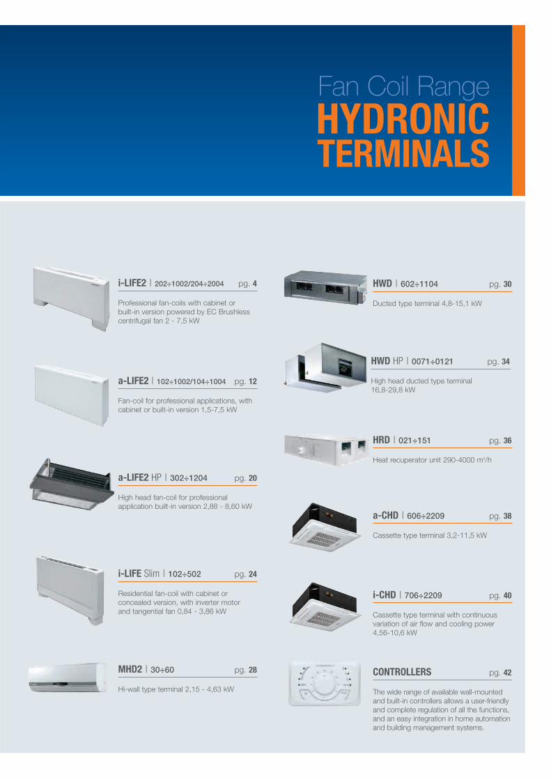
i-LIFE Slim | 102÷502 pg. 24
Residential fan-coil with cabinet orconcealed version, with inverter motorand tangential fan 0,84 - 3,86 kW
HWD | 602÷1104 pg. 30
Ducted type terminal 4,8-15,1 kW
HWD HP | 0071÷0121 pg. 34
High head ducted type terminal16,8-29,8 kW
HRD | 021÷151 pg. 36
Heat recuperator unit 290-4000 m3/h
a-CHD | 606÷2209 pg. 38
Cassette type terminal 3,2-11,5 kW
i-LIFE2 | 202÷1002/204÷2004 pg. 4
Professional fan-coils with cabinet orbuilt-in version powered by EC Brushlesscentrifugal fan 2 - 7,5 kW
a-LIFE2 | 102÷1002/104÷1004 pg. 12
Fan-coil for professional applications, withcabinet or built-in version 1,5-7,5 kW
a-LIFE2 HP | 302÷1204 pg. 20
High head fan-coil for professionalapplication built-in version 2,88 - 8,60 kW
i-CHD | 706÷2209 pg. 40
Cassette type terminal with continuousvariation of air flow and cooling power4,56-10,6 kW
Fan Coil RangeHYDRONICTERMINALS
MHD2 | 30÷60 pg. 28
Hi-wall type terminal 2,15 - 4,63 kW
CONTROLLERS pg. 42
The wide range of available wall-mountedand built-in controllers allows a user-friendlyand complete regulation of all the functions,and an easy integration in home automationand building management systems.
i-LIFE2
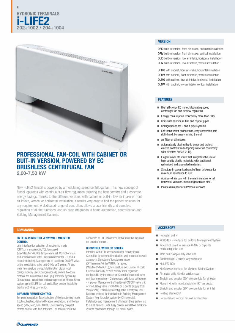
PROFESSIONAL FAN-COIL WITH CABINET ORBUIT-IN VERSION, POWERED BY ECBRUSHLESS CENTRIFUGAL FAN2,00-7,50 kW
New i-LIFE2 fancoil is powered by a modulating speed centrifugal fan. This new concept offancoil operates with continuous air flow regulation assuring the best comfort and a concreteenergy savings. Thanks to the different versions, with cabinet or buit-in, low air intake or frontair intake, vertical or horizontal installation, it results very easy to find the perfect solution forany requirement. A dedicated range of controllers allows a user friendly and completeregulation of all the functions, and an easy integration in home automation, centralization andBuilding Management Systems.
High efficiency EC motor. Modulating speedcentrifugal fan and air flow regulation.
Energy consumption reduced by more than 50%
Coils with aluminium fins and copper pipes.
Configurations for 2 and 4 pipe Systems.
Left-hand water connections, easy convertible intoright-hand, by simply turning the coil
Air filter on all models.
Automatically closing flap to cover and protectelectric controls from dripping water (in conformitywith directive 60335-2-40).
Elegant cover structure that integrates the use ofhigh quality plastic materials, with traditionalgalvanized and precoated materials.
Structure in galvanised steel of high thickness formaximum resistance to rust.
Auxiliary drain pan with thermal insulation for allHorizontal versions, made of galvanized steel.
Plastic drain pan for all Vertical versions.
EK PLUG-IN CONTROL /EKW WALL MOUNTEDCONTROLUser interface for selection of functioning mode(OFF/summer/winter/AUTO), fan speed(Max/Med/Min/AUTO), temperature set. Control of mainand additional coil valve unit (summer/winter - 2 and 4pipes installation). Management of traditional ON/OFF valveunit or modulating valve unit 0-10V or 3 points. Air andwater temperature probe. Multifunction digital inputconfigurable by user. Configuration dip switch. Modbusprotocol for installation in BMS (e.g. Idrorelax system byClimaveneta). Installation and management of Master-Slavesystem up to 8 LIFE fan coil units. Easy control installationthanks to 2 wires connection.
INFRARED REMOTE CONTROLSet-point regulation. Easy selection of the functioning mode(cooling, heating, dehumidification, ventilation), and the fanspeed (Max, Med, Min, AUTO). User-sfriendly compactremote control with fine aethetics. The receiver must be
connected to i-HB Power Board that must be mountedon board of the unit.
IK CONTROL WITH LCD SCREENInterface with LCD screen with user-friendly icons.Control kit for universal installation: wall-mounted as wellas plug-in. Selection of functioning mode(OFF/summer/winter/AUTO), fan speed(Max/Med/Min/AUTO), temperature set. Control iK couldfunction manually or with weekly timer regulationconfigurable by the customer. Control of main coil valveunit (summer/winter - 2 pipes) and additional coil (winter- 4 pipes). Management of traditional ON/OFF valve unitor modulating valve unit 0-10V or 3 points (supply 230VAC or 24V). Parameters configurable directly by user.Modbus protocol for installation in Building ManagementSystem (e.g. Idrorelax system by Climaveneta).Installation and management of Master-Slave system upto 8 LIFE fan coil units. Easy control installation thanks to2 wires connection through HB power board.
Hot water coil kit
Kit RS485 - interface for Building Management System
Kit control board to manage 0-10V or 3 pointsmodulating valve unit
Main coil 2-way/3-way valve unit
Additional coil 2-way/3-way valve unit
Kit LIFE2 BOX
Kit Gateway interface for MyHome Bticino System
Air intake grille kit with version cover
Straight and angular (90°) plenum kits for air outlet
Plenum kit with round, straight or 90° air ducts.
Straight and angular (90°) plenum kits for air inlet
Heating element kit
Horizontal and vertical fan coil auxiliary tray
HYDRONIC TERMINALS
202÷1002 / 204÷1004
COMMANDS
VERSION
FEATURES
ACCESSORY
4
DFIO built-in version, front air intake, horizontal installation
DFIV built-in version, front air intake, vertical installation
DLIO built-in version, low air intake, horizontal installation
DLIV built-in version, low air intake, vertical installation.
DFMO with cabinet, front air intake, horizontal installation
DFMV with cabinet, front air intake, vertical installation
DLMO with cabinet, low air intake, horizontal installation
DLMV with cabinet, low air intake, vertical installation
CONTROLLER4 PIPES
4P
2 PIPES
2P
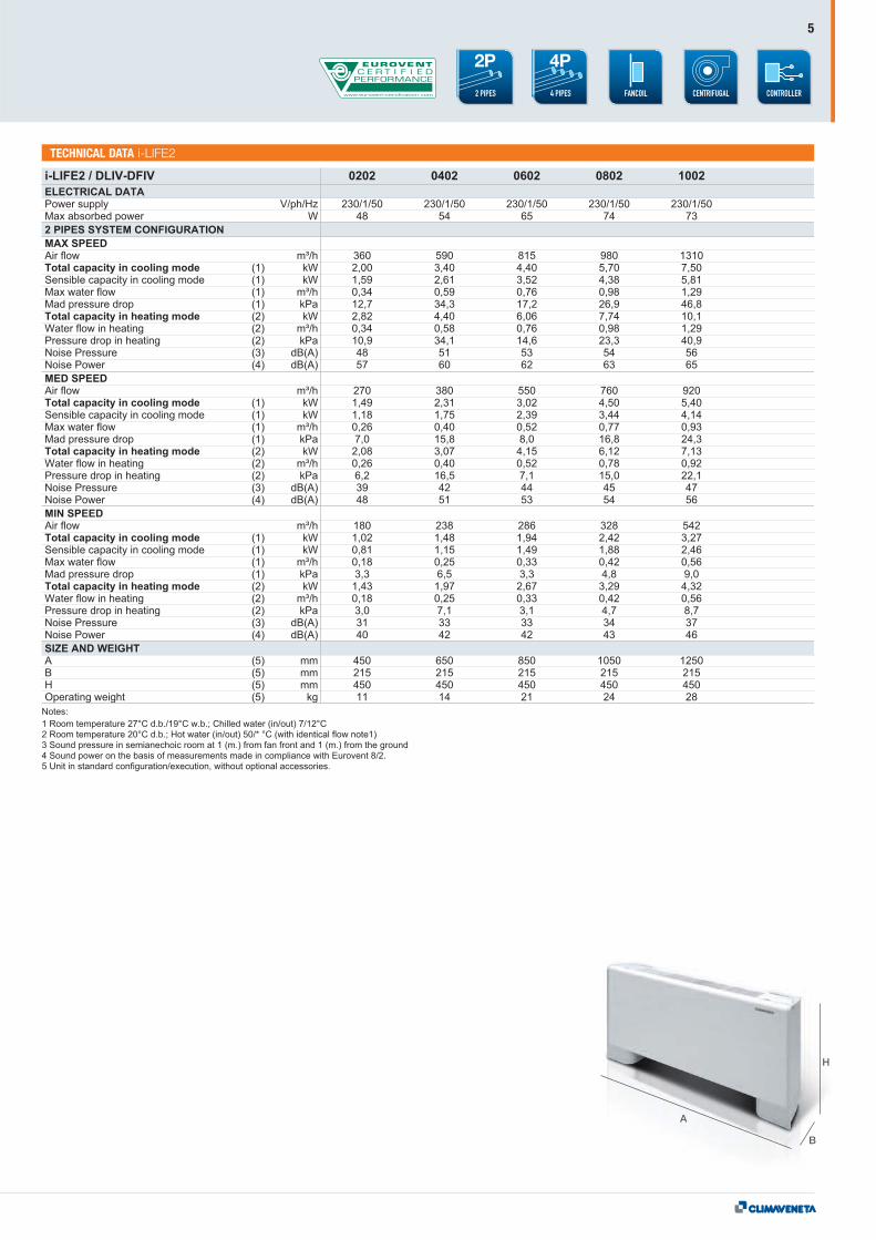
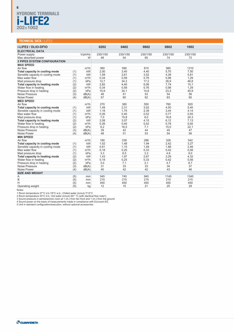
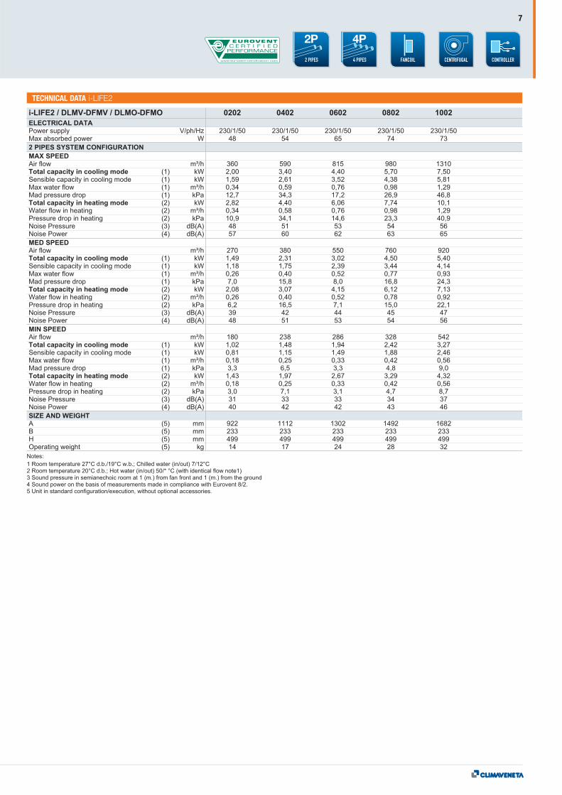
TECHNICAL DATA i-LIFE2
5
A
B
H
TECHNICAL DATA i-LIFE2
i-LIFE2HYDRONIC TERMINALS
202÷1002
6
TECHNICAL DATA i-LIFE2
CONTROLLER4 PIPES
4P
2 PIPES
2P
7
TECHNICAL DATA i-LIFE2
i-LIFE2HYDRONIC TERMINALS
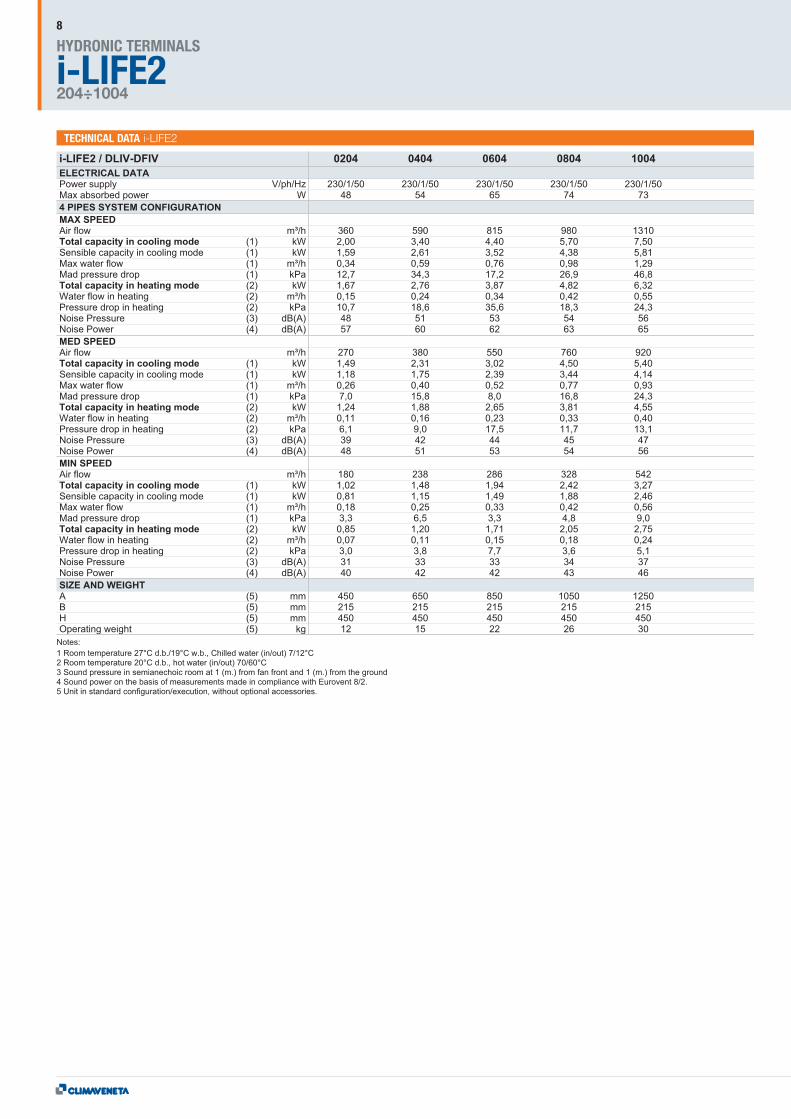
204÷1004
8
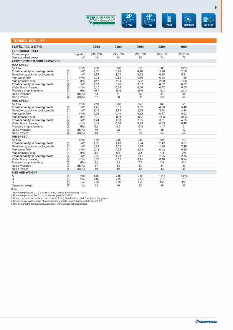
TECHNICAL DATA i-LIFE2
CONTROLLER4 PIPES
4P
2 PIPES
2P
9

TECHNICAL DATA i-LIFE2
i-LIFE2HYDRONIC TERMINALS
204÷1004
10
CONTROLLER4 PIPES
4P
2 PIPES
2P
11
a-LIFE2HYDRONIC TERMINALS
102÷1002 / 104÷1004
12
DLMV with cabinet, low air intake, vertical installation
DLMO with cabinet, low air intake, horizontal installation
DFMV with cabinet, front air intake, vertical installation
DFMO with cabinet, front air intake, horizontal installation
DLIV built-in version, low air intake, vertical installation.
DLIO built-in version, low air intake, horizontal installation
DFIV built-in version, front air intake, vertical installation
DFIO built-in version, front air intake, horizontal installation
Centrifugal Fan with double air inlet, to ensure thebest performances with the best acousticemissions.
Coils with aluminium fins and copper pipes.
Configurations for 2 and 4 pipe Systems.
Left-hand water connections, easy convertible intoright-hand, by simply turning the coil
6-speed autotransformer;
Air filter on all models.
Automatically closing flap to cover and protectelectric controls from dripping water (in conformitywith directive 60335-2-40).
Auxiliary drain pan with thermal insulation for allHorizontal versions, made of galvanized steel.
Plastic drain pan for all Vertical versions.
PS PLUG-IN/PSW WALL MOUNTEDFan speed slider, mode slider (OFF/summer/winter). ON/OFFvalve unit control (summer/winter for 2 pipes installation),ON/OFF second valve unit control (winter for 4 pipesinstallation). Remote water temperature probe.
MT PLUG-IN/MTW WALL MOUNTEDFan speed slider, mode slider (OFF/summer/winter). Thermostatwith set point regulation. ON/OFF valve unit control(summer/winter for 2 pipes installation), ON/OFF second valveunit control (winter for 4 pipes installation). Room temperatureprobe. Remote water temperature probe.
AT PLUG-IN/ATW WALL MOUNTEDMode button (OFF/summer/winter/AUTO), fan speed button(Max/Med/Min/AUTO). Thermostat with set point regulation.ON/OFF valve unit control (summer/winter for 2 and 4 pipesinstallation). Control of traditional or PWM modulating valveunits. Room temperature probe and water temperature probe.Digital input configurable as: window contact, economy, heatingor cooling remote changeover, periodic ventilation.Configuration dip switch. TTL serial port with Modbus protocolfor installation in BMS.
EK PLUG-IN CONTROL /EKW WALL MOUNTED CONTROLUser interface for selection of functioning mode(OFF/summer/winter/AUTO), fan speed (Max/Med/Min/AUTO),temperature set. Control of main and additional coil valve unit(summer/winter - 2 and 4 pipes installation). Management oftraditional ON/OFF valve unit or modulating valve unit 0-10V or3 points . Air and water temperature probe. Multifunction digital
input configurable by user. Configuration dip switch. Modbusprotocol for installation in BMS (e.g. Idrorelax system byClimaveneta). Installation and management of Master-Slavesystem up to 8 LIFE fan coil units. Easy control installationthanks to 2 wires connection.
IK CONTROL WITH LCD SCREENInterface with LCD screen with user-friendly icons. Control kitfor universal installation: wall-mounted as well as plug-in.Selection of functioning mode (OFF/summer/winter/AUTO),fan speed (Max/Med/Min/AUTO), temperature set.Control iK could function manually or with weekly timerregulation configurable by the customer. Control of main coilvalve unit (summer/winter - 2 pipes) and additional coil(winter - 4 pipes). Management of traditional ON/OFF valveunit or modulating valve unit 0-10V or 3 points (supply 230VAC or 24V). Parameters configurable directly by user.Modbus protocol for installation in Building ManagementSystem (e.g. Idrorelax system by Climaveneta).Installation and management of Master-Slave system up to 8LIFE fan coil units. Easy control installation thanks to 2 wiresconnection through HB power board
INFRARED REMOTE CONTROLSet-point regulation. Easy selection of the functioning mode(cooling, heating, dehumidification, ventilation), and the fanspeed (Max, Med, Min, AUTO). User-sfriendly compactremote control with fine aethetics. The receiver must beconnected to i-HB Power Board that must be mounted onboard of the unit.
Hot water coil kit
Kit Bus Adapter for BMS
Kit RS485 - interface for Building Management System
Kit Gateway interface for MyHome Bticino System
Interface SPB Kit
Kit control board to manage 0-10V or 3 pointsmodulating valve unit
Main and additional coil valve unit ON/OFF, PWM,0-10V, 3 points 2-way or 3-way
Kit LIFE2 BOX
Plenum kit with round, straight or 90° air ducts.
Air intake grille kit with version cover
Horizontal and vertical fan coil auxiliary tray
Electric heaters
COMMANDS
VERSION
FEATURES
ACCESSORY
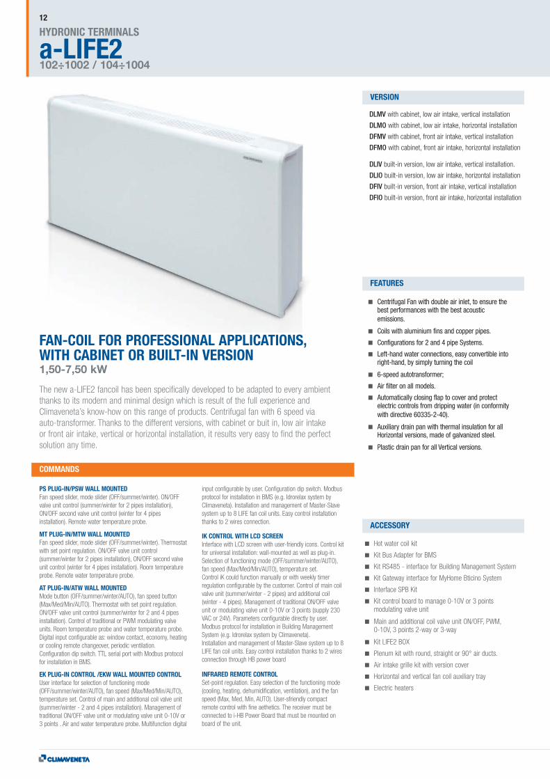
FAN-COIL FOR PROFESSIONAL APPLICATIONS,WITH CABINET OR BUILT-IN VERSION1,50-7,50 kW
The new a-LIFE2 fancoil has been specifically developed to be adapted to every ambientthanks to its modern and minimal design which is result of the full experience andClimaveneta’s know-how on this range of products. Centrifugal fan with 6 speed viaauto-transformer. Thanks to the different versions, with cabinet or buit in, low air intakeor front air intake, vertical or horizontal installation, it results very easy to find the perfectsolution any time.

CONTROLLER4 PIPES
4P
2 PIPES
2P
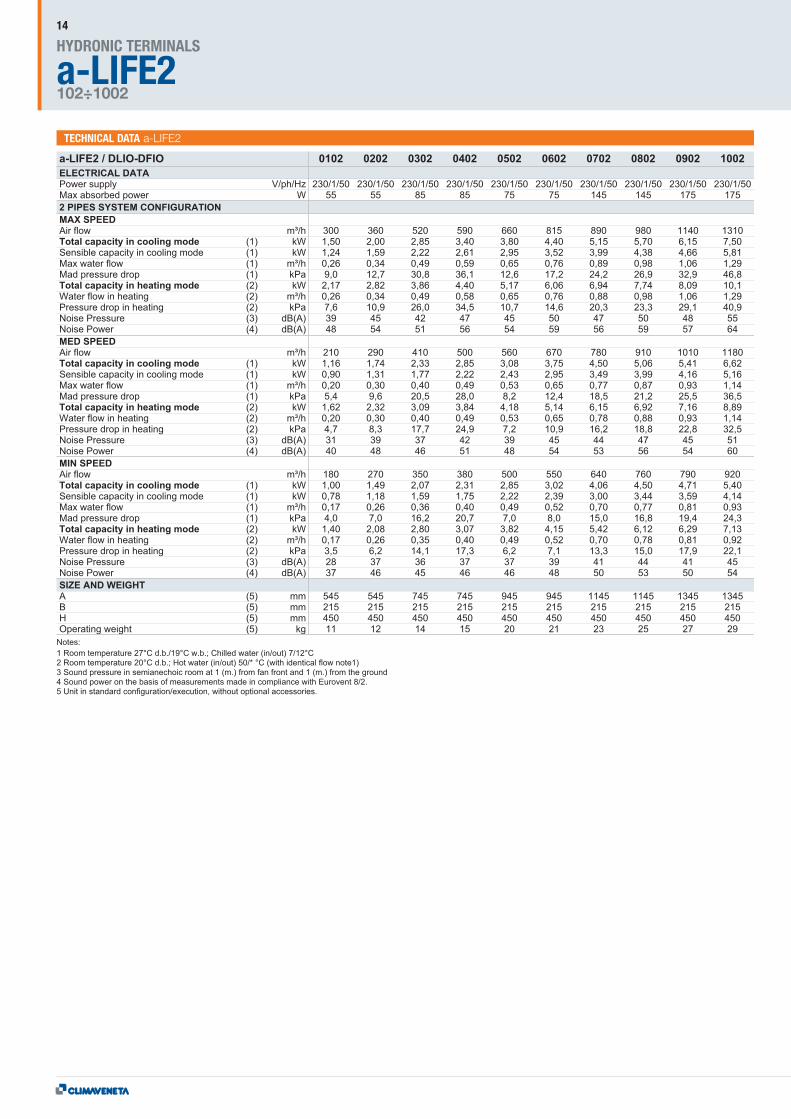
TECHNICAL DATA a-LIFE2
A
B
H
13
a-LIFE2HYDRONIC TERMINALS
102÷1002
14
TECHNICAL DATA a-LIFE2

CONTROLLER4 PIPES
4P
2 PIPES
2P
15
TECHNICAL DATA a-LIFE2

a-LIFE2HYDRONIC TERMINALS
104÷1004
16
TECHNICAL DATA a-LIFE2
CONTROLLER4 PIPES
4P
2 PIPES
2P
17
TECHNICAL DATA a-LIFE2

a-LIFE2HYDRONIC TERMINALS
104÷1004
18
TECHNICAL DATA a-LIFE2
CONTROLLER4 PIPES
4P
2 PIPES
2P
19
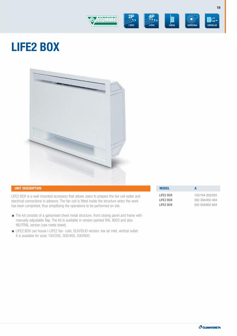
LIFE2 BOX
LIFE2 BOX is a wall-mounted accessory that allows users to prepare the fan coil water andelectrical connections in advance. The fan coil is fitted inside the structure when the workhas been completed, thus simplifying the operations to be performed on site.
The kit consists of a galvanised sheet metal structure, front closing panel and frame withmanually adjustable flap. The kit is available in version painted RAL 9003 and alsoNEUTRAL version (raw metal sheet).
LIFE2 BOX can house i-LIFE2 fan- coils, DLIV/DLIO version: low air inlet, vertical outlet.It is available for sizes 100/200, 300/400, 500/600.
LIFE2 BOX 102/104-202/204 LIFE2 BOX 302-304/402-404LIFE2 BOX 502-504/602-604
UNIT DESCRIPTION MODEL A
AH
B
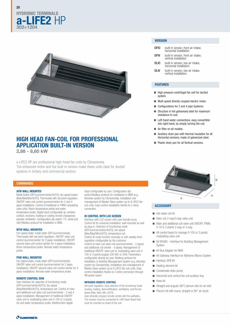
HIGH HEAD FAN-COIL FOR PROFESSIONALAPPLICATION BUILT-IN VERSION2,88 - 8,60 kW
a-LIFE2 HP are professional high-head fan coils by Climaveneta.The enhanced motor and the built-in version make these units ideal for ductedsystems in tertiary and commercial sectors.
DFIO built-in version, front air intake,horizontal installation
DFIV built-in version, front air intake,vertical installation
DLIO built-in version, low air intake,horizontal installation
DLIV built-in version, low air intake,vertical installation.
High pressure centrifugal fan unit for ductedsystem.
Multi speed directly coupled electric motor.
Configurations for 2 and 4 pipe Systems.
Structure in hot galvanised steel for maximumresistance to rust.
Left-hand water connections, easy convertibleinto right-hand, by simply turning the coil.
Air filter on all models.
Auxiliary drain pan with thermal insulation for allHorizontal versions, made of galvanized steel.
Plastic drain pan for all Vertical versions.
ATW WALL MOUNTEDMode button (OFF/summer/winter/AUTO), fan speed button(Max/Med/Min/AUTO). Thermostat with set point regulation.ON/OFF valve unit control (summer/winter for 2 and 4pipes installation). Control of traditional or PWM modulatingvalve units. Room temperature probe and watertemperature probe. Digital input configurable as: windowcontact, economy, heating or cooling remote changeover,periodic ventilation. Configuration dip switch. TTL serial portwith Modbus protocol for installation in BMS.
MTW WALL MOUNTEDFan speed slider, mode slider (OFF/summer/winter).Thermostat with set point regulation. ON/OFF valve unitcontrol (summer/winter for 2 pipes installation), ON/OFFsecond valve unit control (winter for 4 pipes installation).Room temperature probe. Remote water temperatureprobe.
PSW WALL MOUNTEDFan speed slider, mode slider (OFF/summer/winter).ON/OFF valve unit control (summer/winter for 2 pipesinstallation), ON/OFF second valve unit control (winter for 4pipes installation). Remote water temperature probe.
REMOTE CONTROL EKWUser interface for selection of functioning mode(OFF/summer/winter/AUTO), fan speed(Max/Med/Min/AUTO), temperature set. Control of mainand additional coil valve unit (summer/winter - 2 and 4pipes installation). Management of traditional ON/OFFvalve unit or modulating valve unit 0-10V or 3 points.Air and water temperature probe. Multifunction digital
input configurable by user. Configuration dipswitch.Modbus protocol for installation in BMS (e.g.Idrorelax system by Climaveneta). Installation andmanagement of Master-Slave system up to 8 LIFE2 fancoil units. Easy control installation thanks to 2 wiresconnection.
IK CONTROL WITH LCD SCREENInterface with LCD screen with user-friendly icons.Control kit for universal installation: wall-mounted as wellas plug-in. Selection of functioning mode(OFF/summer/winter/AUTO), fan speed(Max/Med/Min/AUTO), temperature set.Control iK could function manually or with weekly timerregulation configurable by the customer.Control of main coil valve unit (summer/winter - 2 pipes)and additional coil (winter - 4 pipes). Management oftraditional ON/OFF valve unit or modulating valve unit 0-10V or 3 points (supply 230 VAC or 24V). Parametersconfigurable directly by user. Modbus protocol forinstallation in Building Management System (e.g. Idrorelaxsystem by Climaveneta). Installation and management ofMaster-Slave system up to 8 LIFE2 fan coil units. Easycontrol installation thanks to 2 wires connection throughHB power board
INFRARED REMOTE CONTROLSet-point regulation. Easy selection of the functioning mode(cooling, heating, dehumidification, ventilation), and the fanspeed (Max, Med, Min, AUTO).User-sfriendly compact remote control with fine aethetics.The receiver must be connected to i-HB Power Board thatmust be mounted on board of the unit.
Hot water coil kit
Main coil 2-way/3-way valve unit
Main and additional coil valve unit ON/OFF, PWM,0-10 V, 3 points 2-way or 3-way
Kit control board to manage 0-10V or 3 pointsmodulating valve unit
Kit RS485 - interface for Building ManagementSystem
Kit Bus Adapter for BMS
Kit Gateway interface for MyHome Bticino System
Interface SPB Kit
Heating element kit
Condensate drain pump
Horizontal and vertical fan coil auxiliary tray
Hose kit
Straight and angular (90°) plenum kits for air inlet
Plenum kit with round, straight or 90° air ducts.
COMMANDS
VERSION
FEATURES
ACCESSORY
a-LIFE2 HPHYDRONIC TERMINALS
302÷1204
20
TECHNICAL DATA a-LIFE HP
CONTROLLERDUCT4 PIPES
4P
2 PIPES
2P
21
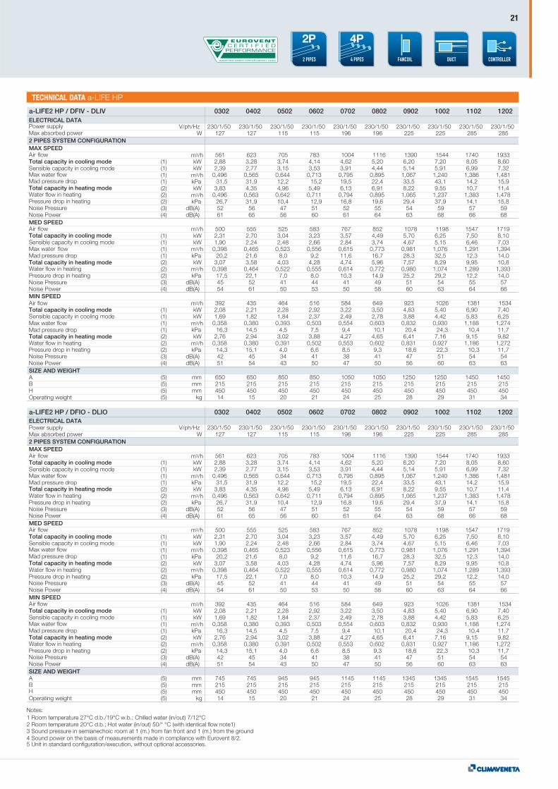
a-LIFE2 HP / DFIV - DLIV 0302 0402 0502 0602 0702 0802 0902 1002 1102 1202
V/ph/Hz 230/1/50 230/1/50 230/1/50 230/1/50 230/1/50 230/1/50 230/1/50 230/1/50 230/1/50 230/1/50W 127 127 115 115 196 196 225 225 285 285
561 623 705 783 1004 1116 1390 1544 1740 1933(1) kW 2,88 3,28 3,74 4,14 4,62 5,20 6,20 7,20 8,05 8,60(1) kW 2,39 2,77 3,15 3,53 3,91 4,44 5,14 5,91 6,99 7,32(1) 0,496 0,565 0,644 0,713 0,795 0,895 1,067 1,240 1,386 1,481(1) kPa 31,5 31,9 12,2 15,2 19,5 22,4 33,5 43,1 14,2 15,9(2) kW 3,83 4,35 4,96 5,49 6,13 6,91 8,22 9,55 10,7 11,4(2) 0,496 0,563 0,642 0,711 0,794 0,895 1,065 1,237 1,383 1,478(2) kPa 26,7 31,9 10,4 12,9 16,8 19,6 29,4 37,9 14,1 15,8(3) dB(A) 52 56 47 51 52 55 54 59 57 59(4) dB(A) 61 65 56 60 61 64 63 68 66 68
500 555 525 583 767 852 1078 1198 1547 1719(1) kW 2,31 2,70 3,04 3,23 3,57 4,49 5,70 6,25 7,50 8,10(1) kW 1,90 2,24 2,48 2,66 2,84 3,74 4,67 5,15 6,46 7,03(1) 0,398 0,465 0,523 0,556 0,615 0,773 0,981 1,076 1,291 1,394(1) kPa 20,2 21,6 8,0 9,2 11,6 16,7 28,3 32,5 12,3 14,0(2) kW 3,07 3,58 4,03 4,28 4,74 5,96 7,57 8,29 9,95 10,8(2) 0,398 0,464 0,522 0,555 0,614 0,772 0,980 1,074 1,289 1,393(2) kPa 17,5 22,1 7,0 8,0 10,3 14,9 25,2 29,2 12,2 14,0(3) dB(A) 45 52 41 44 41 49 51 54 55 57(4) dB(A) 54 61 50 53 50 58 60 63 64 66
392 435 464 516 584 649 923 1026 1381 1534(1) kW 2,08 2,21 2,28 2,92 3,22 3,50 4,83 5,40 6,90 7,40(1) kW 1,69 1,82 1,84 2,37 2,49 2,78 3,88 4,42 5,83 6,25(1) 0,358 0,380 0,393 0,503 0,554 0,603 0,832 0,930 1,188 1,274(1) kPa 16,3 14,5 4,5 7,5 9,4 10,1 20,4 24,3 10,4 11,7(2) kW 2,76 2,94 3,02 3,88 4,27 4,65 6,41 7,16 9,15 9,82(2) 0,358 0,380 0,391 0,502 0,553 0,602 0,831 0,927 1,186 1,272(2) kPa 14,3 15,1 4,0 6,6 8,5 9,3 18,6 22,3 10,3 11,7(3) dB(A) 42 45 34 41 38 41 47 51 54 54(4) dB(A) 51 54 43 50 47 50 56 60 63 63
(5) mm 650 650 850 850 1050 1050 1250 1250 1450 1450(5) mm 215 215 215 215 215 215 215 215 215 215(5) mm 450 450 450 450 450 450 450 450 450 450(5) kg 14 15 20 21 24 25 28 29 31 34
m3/h
m3/h
m3/h
m3/h
m3/h
m3/h
m3/h
m3/h
m3/h
a-LIFE2 HP / DFIO - DLIO 0302 0402 0502 0602 0702 0802 0902 1002 1102 1202
V/ph/Hz 230/1/50 230/1/50 230/1/50 230/1/50 230/1/50 230/1/50 230/1/50 230/1/50 230/1/50 230/1/50W 127 127 115 115 196 196 225 225 285 285
561 623 705 783 1004 1116 1390 1544 1740 1933(1) kW 2,88 3,28 3,74 4,14 4,62 5,20 6,20 7,20 8,05 8,60(1) kW 2,39 2,77 3,15 3,53 3,91 4,44 5,14 5,91 6,99 7,32(1) 0,496 0,565 0,644 0,713 0,795 0,895 1,067 1,240 1,386 1,481(1) kPa 31,5 31,9 12,2 15,2 19,5 22,4 33,5 43,1 14,2 15,9(2) kW 3,83 4,35 4,96 5,49 6,13 6,91 8,22 9,55 10,7 11,4(2) 0,496 0,563 0,642 0,711 0,794 0,895 1,065 1,237 1,383 1,478(2) kPa 26,7 31,9 10,4 12,9 16,8 19,6 29,4 37,9 14,1 15,8(3) dB(A) 52 56 47 51 52 55 54 59 57 59(4) dB(A) 61 65 56 60 61 64 63 68 66 68
500 555 525 583 767 852 1078 1198 1547 1719(1) kW 2,31 2,70 3,04 3,23 3,57 4,49 5,70 6,25 7,50 8,10(1) kW 1,90 2,24 2,48 2,66 2,84 3,74 4,67 5,15 6,46 7,03(1) 0,398 0,465 0,523 0,556 0,615 0,773 0,981 1,076 1,291 1,394(1) kPa 20,2 21,6 8,0 9,2 11,6 16,7 28,3 32,5 12,3 14,0(2) kW 3,07 3,58 4,03 4,28 4,74 5,96 7,57 8,29 9,95 10,8(2) 0,398 0,464 0,522 0,555 0,614 0,772 0,980 1,074 1,289 1,393(2) kPa 17,5 22,1 7,0 8,0 10,3 14,9 25,2 29,2 12,2 14,0(3) dB(A) 45 52 41 44 41 49 51 54 55 57(4) dB(A) 54 61 50 53 50 58 60 63 64 66
392 435 464 516 584 649 923 1026 1381 1534(1) kW 2,08 2,21 2,28 2,92 3,22 3,50 4,83 5,40 6,90 7,40(1) kW 1,69 1,82 1,84 2,37 2,49 2,78 3,88 4,42 5,83 6,25(1) 0,358 0,380 0,393 0,503 0,554 0,603 0,832 0,930 1,188 1,274(1) kPa 16,3 14,5 4,5 7,5 9,4 10,1 20,4 24,3 10,4 11,7(2) kW 2,76 2,94 3,02 3,88 4,27 4,65 6,41 7,16 9,15 9,82(2) 0,358 0,380 0,391 0,502 0,553 0,602 0,831 0,927 1,186 1,272(2) kPa 14,3 15,1 4,0 6,6 8,5 9,3 18,6 22,3 10,3 11,7(3) dB(A) 42 45 34 41 38 41 47 51 54 54(4) dB(A) 51 54 43 50 47 50 56 60 63 63
(5) mm 745 745 945 945 1145 1145 1345 1345 1545 1545(5) mm 215 215 215 215 215 215 215 215 215 215(5) mm 450 450 450 450 450 450 450 450 450 450(5) kg 14 15 20 21 24 25 28 29 31 34
m3/h
m3/h
m3/h
m3/h
m3/h
m3/h
m3/h
m3/h
m3/h
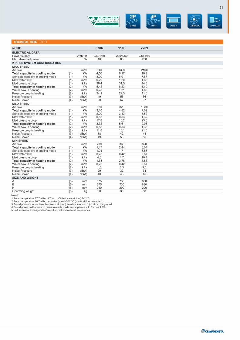
ELECTRICAL DATAPower supplyMax absorbed power2 PIPES SYSTEM CONFIGURATIONMAX SPEEDAir flowTotal capacity in cooling modeSensible capacity in cooling modeMax water flowMad pressure dropTotal capacity in heating modeWater flow in heatingPressure drop in heatingNoise PressureNoise PowerMED SPEEDAir flowTotal capacity in cooling modeSensible capacity in cooling modeMax water flowMad pressure dropTotal capacity in heating modeWater flow in heatingPressure drop in heatingNoise PressureNoise PowerMIN SPEEDAir flowTotal capacity in cooling modeSensible capacity in cooling modeMax water flowMad pressure dropTotal capacity in heating modeWater flow in heatingPressure drop in heatingNoise PressureNoise PowerSIZE AND WEIGHTABHOperating weight
Notes:1 Room temperature 27°C d.b./19°C w.b.; Chilled water (in/out) 7/12°C2 Room temperature 20°C d.b.; Hot water (in/out) 50/* °C (with identical flow note1)3 Sound pressure in semianechoic room at 1 (m.) from fan front and 1 (m.) from the ground4 Sound power on the basis of measurements made in compliance with Eurovent 8/2.5 Unit in standard configuration/execution, without optional accessories.
ELECTRICAL DATAPower supplyMax absorbed power2 PIPES SYSTEM CONFIGURATIONMAX SPEEDAir flowTotal capacity in cooling modeSensible capacity in cooling modeMax water flowMad pressure dropTotal capacity in heating modeWater flow in heatingPressure drop in heatingNoise PressureNoise PowerMED SPEEDAir flowTotal capacity in cooling modeSensible capacity in cooling modeMax water flowMad pressure dropTotal capacity in heating modeWater flow in heatingPressure drop in heatingNoise PressureNoise PowerMIN SPEEDAir flowTotal capacity in cooling modeSensible capacity in cooling modeMax water flowMad pressure dropTotal capacity in heating modeWater flow in heatingPressure drop in heatingNoise PressureNoise PowerSIZE AND WEIGHTABHOperating weight
22
TECHNICAL DATA a-LIFE HP
a-LIFE2 HP / DFIV - DLIV 0304 0404 0504 0604 0704 0804 0904 1004 1104 1204
V/ph/HzW
(1) kW(1) kW(1)(1) kPa(2) kW(2)(2) kPa(3) dB(A)(4) dB(A)
(1) kW(1) kW(1)(1) kPa(2) kW(2)(2) kPa(3) dB(A)(4) dB(A)
(1) kW(1) kW(1)(1) kPa(2) kW(2)(2) kPa(3) dB(A)(4) dB(A)
(5) mm(5) mm(5) mm(5) kg
230/1/50 230/1/50 230/1/50 230/1/50 230/1/50 230/1/50 230/1/50 230/1/50 230/1/50 230/1/50127 127 115 115 196 196 225 225 285 285
561 623 705 783 1004 1116 1390 1544 1740 19332,88 3,28 3,74 4,14 4,62 5,20 6,20 7,20 8,05 8,602,39 2,77 3,15 3,53 3,91 4,44 5,14 5,91 6,99 7,320,496 0,565 0,644 0,713 0,795 0,895 1,067 1,240 1,386 1,48131,5 31,9 12,2 15,2 19,5 22,4 33,5 43,1 14,2 15,92,34 2,66 3,29 3,64 3,71 4,18 4,96 5,76 6,44 6,880,205 0,233 0,288 0,319 0,325 0,366 0,435 0,505 0,565 0,60313,6 17,3 26,3 31,7 11,1 13,9 15,4 20,4 17,9 20,152 56 47 51 52 55 54 59 57 5961 65 56 60 61 64 63 68 66 68
500 555 525 583 767 852 1078 1198 1547 17192,31 2,70 3,04 3,23 3,57 4,49 5,70 6,25 7,50 8,101,90 2,24 2,48 2,66 2,84 3,74 4,67 5,15 6,46 7,030,398 0,465 0,523 0,556 0,615 0,773 0,981 1,076 1,291 1,39420,2 21,6 8,0 9,2 11,6 16,7 28,3 32,5 12,3 14,01,88 2,19 2,67 2,84 2,87 3,61 4,56 5,00 6,00 6,480,165 0,192 0,234 0,249 0,252 0,316 0,400 0,438 0,526 0,5689,0 12,0 17,8 20,0 6,8 10,5 13,1 15,6 15,7 18,145 52 41 44 41 49 51 54 55 5754 61 50 53 50 58 60 63 64 66
392 435 464 516 584 649 923 1026 1381 15342,08 2,21 2,28 2,92 3,22 3,50 4,83 5,40 6,90 7,401,69 1,82 1,84 2,37 2,49 2,78 3,88 4,42 5,83 6,250,358 0,380 0,393 0,503 0,554 0,603 0,832 0,930 1,188 1,27416,3 14,5 4,5 7,5 9,4 10,1 20,4 24,3 10,4 11,71,69 1,79 2,00 2,75 2,59 2,81 3,86 4,32 5,52 5,920,148 0,157 0,175 0,225 0,227 0,246 0,338 0,379 0,484 0,5197,3 8,2 10,4 16,6 5,6 6,5 9,6 11,9 13,5 15,442 45 34 41 38 41 47 51 54 5451 54 43 50 47 50 56 60 63 63
650 650 850 850 1050 1050 1250 1250 1450 1450215 215 215 215 215 215 215 215 215 215450 450 450 450 450 450 450 450 450 45015 16 21 22 25 26 29 31 32 35
m3/h
m3/h
m3/h
m3/h
m3/h
m3/h
m3/h
m3/h
m3/h
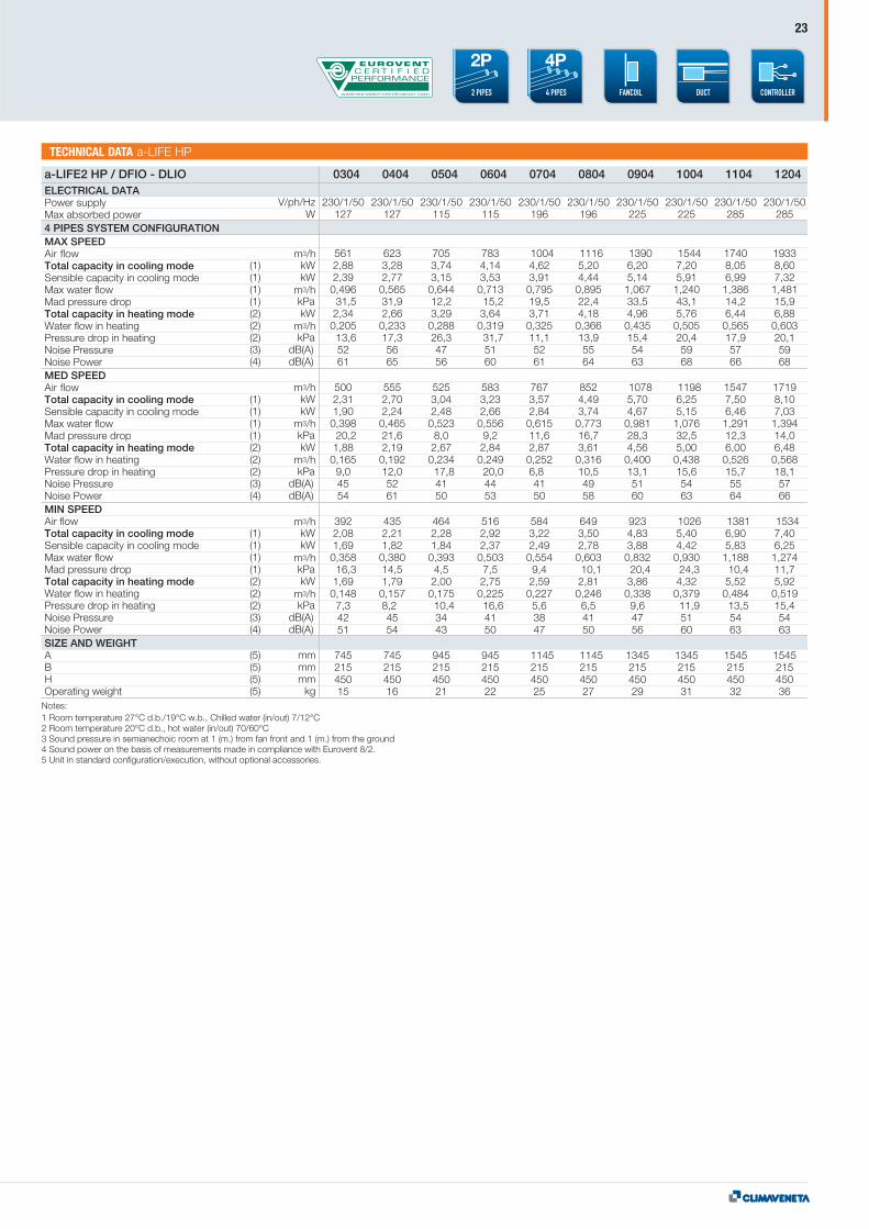
ELECTRICAL DATAPower supplyMax absorbed power4 PIPES SYSTEM CONFIGURATIONMAX SPEEDAir flowTotal capacity in cooling modeSensible capacity in cooling modeMax water flowMad pressure dropTotal capacity in heating modeWater flow in heatingPressure drop in heatingNoise PressureNoise PowerMED SPEEDAir flowTotal capacity in cooling modeSensible capacity in cooling modeMax water flowMad pressure dropTotal capacity in heating modeWater flow in heatingPressure drop in heatingNoise PressureNoise PowerMIN SPEEDAir flowTotal capacity in cooling modeSensible capacity in cooling modeMax water flowMad pressure dropTotal capacity in heating modeWater flow in heatingPressure drop in heatingNoise PressureNoise PowerSIZE AND WEIGHTABHOperating weight
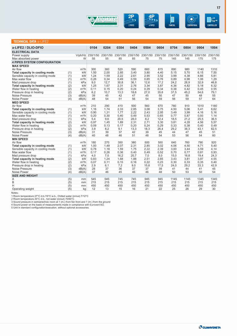
Notes:1 Room temperature 27°C d.b./19°C w.b., Chilled water (in/out) 7/12°C2 Room temperature 20°C d.b., hot water (in/out) 70/60°C3 Sound pressure in semianechoic room at 1 (m.) from fan front and 1 (m.) from the ground4 Sound power on the basis of measurements made in compliance with Eurovent 8/2.5 Unit in standard configuration/execution, without optional accessories.
a-LIFE2 HPHYDRONIC TERMINALS
302÷1204
23
TECHNICAL DATA a-LIFE HP
a-LIFE2 HP / DFIO - DLIO 0304 0404 0504 0604 0704 0804 0904 1004 1104 1204
V/ph/HzW
(1) kW(1) kW(1)(1) kPa(2) kW(2)(2) kPa(3) dB(A)(4) dB(A)
(1) kW(1) kW(1)(1) kPa(2) kW(2)(2) kPa(3) dB(A)(4) dB(A)
(1) kW(1) kW(1)(1) kPa(2) kW(2)(2) kPa(3) dB(A)(4) dB(A)
(5) mm(5) mm(5) mm(5) kg
230/1/50 230/1/50 230/1/50 230/1/50 230/1/50 230/1/50 230/1/50 230/1/50 230/1/50 230/1/50127 127 115 115 196 196 225 225 285 285
561 623 705 783 1004 1116 1390 1544 1740 19332,88 3,28 3,74 4,14 4,62 5,20 6,20 7,20 8,05 8,602,39 2,77 3,15 3,53 3,91 4,44 5,14 5,91 6,99 7,320,496 0,565 0,644 0,713 0,795 0,895 1,067 1,240 1,386 1,48131,5 31,9 12,2 15,2 19,5 22,4 33,5 43,1 14,2 15,92,34 2,66 3,29 3,64 3,71 4,18 4,96 5,76 6,44 6,880,205 0,233 0,288 0,319 0,325 0,366 0,435 0,505 0,565 0,60313,6 17,3 26,3 31,7 11,1 13,9 15,4 20,4 17,9 20,152 56 47 51 52 55 54 59 57 5961 65 56 60 61 64 63 68 66 68
500 555 525 583 767 852 1078 1198 1547 17192,31 2,70 3,04 3,23 3,57 4,49 5,70 6,25 7,50 8,101,90 2,24 2,48 2,66 2,84 3,74 4,67 5,15 6,46 7,030,398 0,465 0,523 0,556 0,615 0,773 0,981 1,076 1,291 1,39420,2 21,6 8,0 9,2 11,6 16,7 28,3 32,5 12,3 14,01,88 2,19 2,67 2,84 2,87 3,61 4,56 5,00 6,00 6,480,165 0,192 0,234 0,249 0,252 0,316 0,400 0,438 0,526 0,5689,0 12,0 17,8 20,0 6,8 10,5 13,1 15,6 15,7 18,145 52 41 44 41 49 51 54 55 5754 61 50 53 50 58 60 63 64 66
392 435 464 516 584 649 923 1026 1381 15342,08 2,21 2,28 2,92 3,22 3,50 4,83 5,40 6,90 7,401,69 1,82 1,84 2,37 2,49 2,78 3,88 4,42 5,83 6,250,358 0,380 0,393 0,503 0,554 0,603 0,832 0,930 1,188 1,27416,3 14,5 4,5 7,5 9,4 10,1 20,4 24,3 10,4 11,71,69 1,79 2,00 2,75 2,59 2,81 3,86 4,32 5,52 5,920,148 0,157 0,175 0,225 0,227 0,246 0,338 0,379 0,484 0,5197,3 8,2 10,4 16,6 5,6 6,5 9,6 11,9 13,5 15,442 45 34 41 38 41 47 51 54 5451 54 43 50 47 50 56 60 63 63
745 745 945 945 1145 1145 1345 1345 1545 1545215 215 215 215 215 215 215 215 215 215450 450 450 450 450 450 450 450 450 45015 16 21 22 25 27 29 31 32 36
m3/h
m3/h
m3/h
m3/h
m3/h
m3/h
m3/h
m3/h
m3/h
ELECTRICAL DATAPower supplyMax absorbed power4 PIPES SYSTEM CONFIGURATIONMAX SPEEDAir flowTotal capacity in cooling modeSensible capacity in cooling modeMax water flowMad pressure dropTotal capacity in heating modeWater flow in heatingPressure drop in heatingNoise PressureNoise PowerMED SPEEDAir flowTotal capacity in cooling modeSensible capacity in cooling modeMax water flowMad pressure dropTotal capacity in heating modeWater flow in heatingPressure drop in heatingNoise PressureNoise PowerMIN SPEEDAir flowTotal capacity in cooling modeSensible capacity in cooling modeMax water flowMad pressure dropTotal capacity in heating modeWater flow in heatingPressure drop in heatingNoise PressureNoise PowerSIZE AND WEIGHTABHOperating weight
Notes:1 Room temperature 27°C d.b./19°C w.b., Chilled water (in/out) 7/12°C2 Room temperature 20°C d.b., hot water (in/out) 70/60°C3 Sound pressure in semianechoic room at 1 (m.) from fan front and 1 (m.) from the ground4 Sound power on the basis of measurements made in compliance with Eurovent 8/2.5 Unit in standard configuration/execution, without optional accessories.
CONTROLLERDUCT4 PIPES
4P
2 PIPES
2P
A
B
H
i-LIFE SlimHYDRONIC TERMINALS
102÷502
24
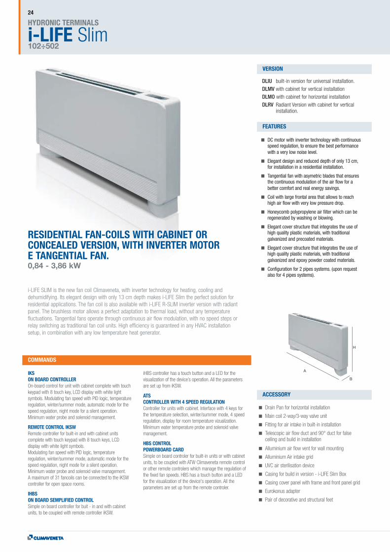
RESIDENTIAL FAN-COILS WITH CABINET ORCONCEALED VERSION, WITH INVERTER MOTORE TANGENTIAL FAN.0,84 - 3,86 kW
i-LIFE SLIM is the new fan coil Climaveneta, with inverter technology for heating, cooling anddehumidifying. Its elegant design with only 13 cm depth makes i-LIFE Slim the perfect solution forresidential applications. The fan coil is also available with i-LIFE R-SLIM inverter version with radiantpanel. The brushless motor allows a perfect adaptation to thermal load, without any temperaturefluctuations. Tangential fans operate through continuous air flow modulation, with no speed steps orrelay switching as traditional fan coil units. High efficiency is guaranteed in any HVAC installationsetup, in combination with any low temperature heat generator.
DLIU built-in version for universal installation.DLMV with cabinet for vertical installationDLMO with cabinet for horizontal installationDLRV Radiant Version with cabinet for vertical
installation.
DC motor with inverter technology with continuousspeed regulation, to ensure the best performancewith a very low noise level.
Elegant design and reduced depth of only 13 cm,for installation in a residential installation.
Tangential fan with asymetric blades that ensuresthe continuous modulation of the air flow for abetter comfort and real energy savings.
Coil with large frontal area that allows to reachhigh air flow with very low pressure drop.
Honeycomb polypropylene air filter which can beregenerated by washing or blowing.
Elegant cover structure that integrates the use ofhigh quality plastic materials, with traditionalgalvanized and precoated materials.
Elegant cover structure that integrates the use ofhigh quality plastic materials, with traditionalgalvanized and epoxy powder coated materials.
Configuration for 2 pipes systems. (upon requestalso for 4 pipes systems).
IKSON BOARD CONTROLLEROn-board control for unit with cabinet complete with touchkeypad with 8 touch key, LCD display with white lightsymbols. Modulating fan speed with PID logic, temperatureregulation, winter/summer mode, automatic mode for thespeed regulation, night mode for a silent operation.Minimum water probe and solenoid management.
REMOTE CONTROL IKSWRemote controller for built-in and with cabinet unitscomplete with touch keypad with 8 touch keys, LCDdisplay with white light symbols.Modulating fan speed with PID logic, temperatureregulation, winter/summer mode, automatic mode for thespeed regulation, night mode for a silent operation.Minimum water probe and solenoid valve management.A maximum of 31 fancoils can be connected to the iKSWcontroller for open space rooms.
IHBSON BOARD SEMPLIFIED CONTROLSimple on board controller for buit - in and with cabinetunits, to be coupled with remote controller iKSW.
iHBS controller has a touch button and a LED for thevisualization of the device’s operation. All the parametersare set up from iKSW.
ATSCONTROLLER WITH 4 SPEED REGULATIONController for units with cabinet. Interface with 4 keys forthe temperature selection, winter/summer mode, 4 speedregulation, display for room temperature vizualization.Minimum water temperature probe and solenoid valvemanagement.
HBS CONTROLPOWERBOARD CARDSimple on board controler for built-in units or with cabinetunits, to be coupled with ATW Climaveneta remote controlor other remote controlers which manage the regulation ofthe fixed fan speeds. HBS has a touch button and a LEDfor the visualization of the device's operation. All theparameters are set up from the remote controler.
Drain Pan for horizontal installation
Main coil 2-way/3-way valve unit
Fitting for air intake in built-in installation
Telescopic air flow duct and 90° duct for falseceiling and build in installation
Alluminium air flow vent for wall mounting
Alluminium Air intake grid
UVC air sterilisation device
Casing for build in version - i-LIFE Slim Box
Casing cover panel with frame and front panel grid
Eurokonus adapter
Pair of decorative and structural feet
COMMANDS
VERSION
FEATURES
ACCESSORY
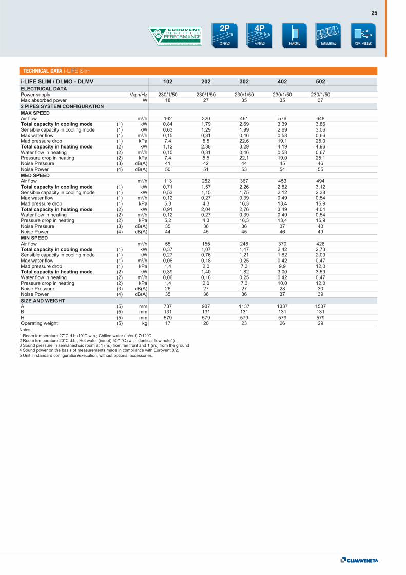
NFT / UTECHNICAL DATA i-LIFE Slim
CONTROLLER4 PIPES
4P
2 PIPES
2P
25
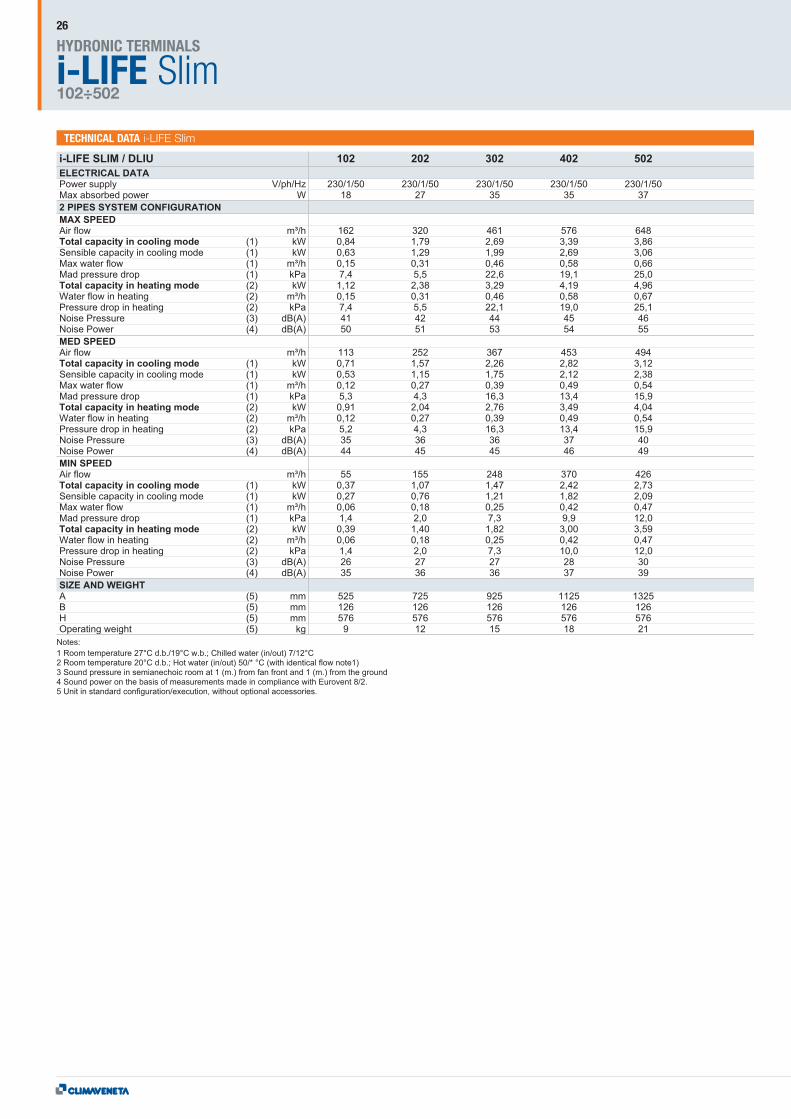
NFT / UTECHNICAL DATA i-LIFE Slim
i-LIFE SlimHYDRONIC TERMINALS
102÷502
26

NFT / UTECHNICAL DATA i-LIFE Slim
CONTROLLER4 PIPES
4P
2 PIPES
2P
27
A B
H
MHD2HYDRONIC TERMINALS
30÷60
28
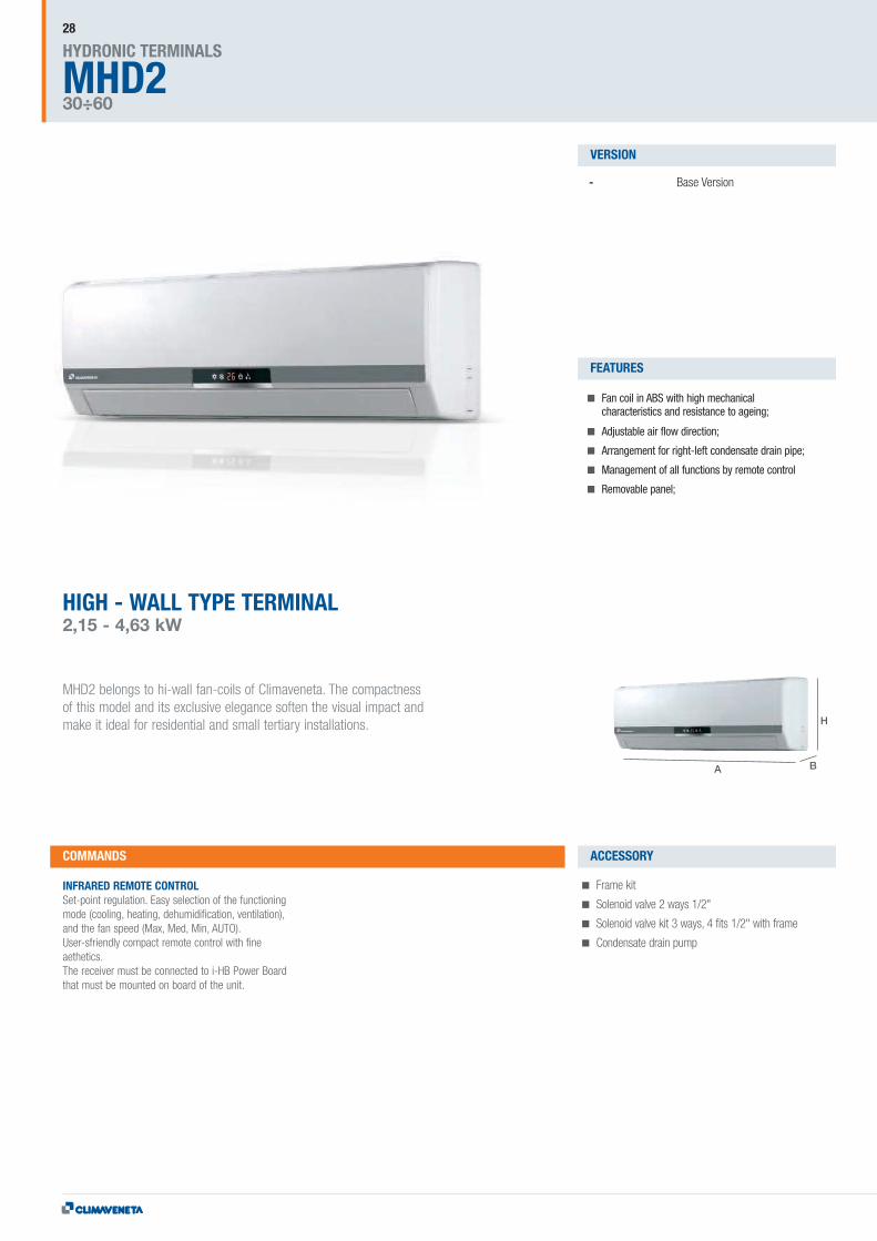
HIGH - WALL TYPE TERMINAL2,15 - 4,63 kW
MHD2 belongs to hi-wall fan-coils of Climaveneta. The compactnessof this model and its exclusive elegance soften the visual impact andmake it ideal for residential and small tertiary installations.
- Base Version
Fan coil in ABS with high mechanicalcharacteristics and resistance to ageing;
Adjustable air flow direction;
Arrangement for right-left condensate drain pipe;
Management of all functions by remote control
Removable panel;
INFRARED REMOTE CONTROLSet-point regulation. Easy selection of the functioningmode (cooling, heating, dehumidification, ventilation),and the fan speed (Max, Med, Min, AUTO).User-sfriendly compact remote control with fineaethetics.The receiver must be connected to i-HB Power Boardthat must be mounted on board of the unit.
Frame kit
Solenoid valve 2 ways 1/2"
Solenoid valve kit 3 ways, 4 fits 1/2" with frame
Condensate drain pump
COMMANDS
VERSION
FEATURES
ACCESSORY
NFT / UTECHNICAL DATA MHD
WALL2 PIPES
2P
29
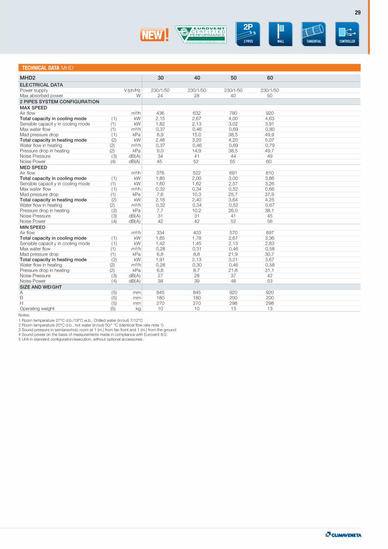
MHD2 30 40 50 60ELECTRICAL DATAPower supply V/ph/Hz 230/1/50 230/1/50 230/1/50 230/1/50Max absorbed power W 24 28 40 502 PIPES SYSTEM CONFIGURATIONMAX SPEEDAir flow m³/h 436 632 780 920Total capacity in cooling mode (1) kW 2,15 2,67 4,00 4,63Sensible capacit y in cooling mode (1) kW 1,82 2,13 3,02 3,91Max water flow (1) m³/h 0,37 0,46 0,69 0,80Mad pressure drop (1) kPa 8,9 15,0 38,5 49,9Total capacity in heating mode (2) kW 2,48 3,20 4,20 5,07Water flow in heating (2) m³/h 0,37 0,46 0,69 0,79Pressure drop in heating (2) kPa 9,0 14,9 38,5 49,7Noise Pressure (3) dB(A) 34 41 44 49Noise Power (4) dB(A) 45 52 55 60MED SPEEDAir flow m³/h 376 522 691 810Total capacity in cooling mode (1) kW 1,85 2,00 3,00 3,86Sensible capacit y in cooling mode (1) kW 1,60 1,62 2,57 3,26Max water flow (1) m³/h 0,32 0,34 0,52 0,66Mad pressure drop (1) kPa 7,6 10,3 25,7 37,9Total capacity in heating mode (2) kW 2,18 2,40 3,64 4,25Water flow in heating (2) m³/h 0,32 0,34 0,52 0,67Pressure drop in heating (2) kPa 7,7 10,2 26,0 38,1Noise Pressure (3) dB(A) 31 31 41 45Noise Power (4) dB(A) 42 42 52 56MIN SPEEDAir flow m³/h 334 403 570 697Total capacity in cooling mode (1) kW 1,65 1,78 2,67 3,36Sensible capacit y in cooling mode (1) kW 1,42 1,45 2,13 2,83Max water flow (1) m³/h 0,28 0,31 0,46 0,58Mad pressure drop (1) kPa 6,8 8,8 21,9 30,7Total capacity in heating mode (2) kW 1,91 2,13 3,21 3,67Water flow in heating (2) m³/h 0,28 0,30 0,46 0,58Pressure drop in heating (2) kPa 6,8 8,7 21,8 31,1Noise Pressure (3) dB(A) 27 28 37 42Noise Power (4) dB(A) 38 39 48 53SIZE AND WEIGHTA (5) mm 845 845 920 920B (5) mm 180 180 200 200H (5) mm 270 270 298 298Operating weight (5) kg 10 10 13 13
Notes:1 Room temperature 27°C d.b./19°C w.b., Chilled water (in/out) 7/12°C2 Room temperature 20°C d.b., hot water (in/out) 50/* °C (identical flow rate note 1)3 Sound pressure in semianechoic room at 1 (m.) from fan front and 1 (m.) from the ground4 Sound power on the basis of measurements made in compliance with Eurovent 8/2.5 Unit in standard configuration/execution, without optional accessories.
CONTROLLER
AB
H
HWDHYDRONIC TERMINALS
602÷1104
30
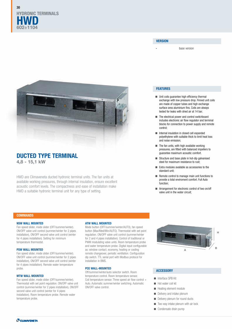
DUCTED TYPE TERMINAL4,8 - 15,1 kW
HWD are Climaveneta ducted hydronic terminal units. The fan units atavailable working pressures, through internal insulation, ensure excellentacoustic comfort levels. The compactness and ease of installation makeHWD a suitable hydronic terminal unit for any type of setting.
- base version
Unit coils guarantee high efficiency thermalexchange with low pressure drop. Finned unit coilsare made of copper tubes and high exchangesurface area aluminium fins. Coils are alwaystested for leaks with dried air at 14 bar;
The electrical power and control switchboardincludes electronic air flow regulator and terminalblocks for connection to power supply and remotecontrol;
Internal insulation in closed cell expandedpolyethylene with suitable thick to limit heat lossand noise emission;
The fan units, with high available workingpressures, are fitted with balanced impellers toguarantee maximum acoustic comfort.
Structure and base plate in hot-dip galvanisedsteel for maximum resistance to rust;
Extra modules available as accessories to thestandard unit;
Remote control to manage main unit functions toprovide a total enviroment comfort. Full Autofunction;
Arrangement for electronic control of two on/offvalve unit in the water circuit;
NSW WALL MOUNTEDFan speed slider, mode slider (OFF/summer/winter).ON/OFF valve unit control (summer/winter for 2 pipesinstallation), ON/OFF second valve unit control (winterfor 4 pipes installation). Setting for minimumtemperature thermostat.
PSW WALL MOUNTEDFan speed slider, mode slider (OFF/summer/winter).ON/OFF valve unit control (summer/winter for 2 pipesinstallation), ON/OFF second valve unit control (winterfor 4 pipes installation). Remote water temperatureprobe.
MTW WALL MOUNTEDFan speed slider, mode slider (OFF/summer/winter).Thermostat with set point regulation. ON/OFF valve unitcontrol (summer/winter for 2 pipes installation), ON/OFFsecond valve unit control (winter for 4 pipesinstallation). Room temperature probe. Remote watertemperature probe.
ATW WALL MOUNTEDMode button (OFF/summer/winter/AUTO), fan speedbutton (Max/Med/Min/AUTO). Thermostat with set pointregulation. ON/OFF valve unit control (summer/winterfor 2 and 4 pipes installation). Control of traditional orPWM modulating valve units. Room temperature probeand water temperature probe. Digital input configurableas: window contact, economy, heating or coolingremote changeover, periodic ventilation. Configurationdip switch. TTL serial port with Modbus protocol forinstallation in BMS.
PCE WALL-MOUNTEDOff/summer/winter/auto selector switch. Roomtemperature control. Room temperature sensor.Coil temperature sensor. Three speed air flow control +Auto. Automatic summer/winter switching. AutomaticON/OFF valve control.
Interface SPB Kit
Hot water coil kit
Heating element module
Delivery and intake plenum
Delivery plenum for round ducts
Two way intake plenum with air lock
Condensate drain pump
COMMANDS
VERSION
FEATURES
ACCESSORY

HWDTECHNICAL DATA HWD
31
CONTROLLER4 PIPES
4P
2 PIPES
2P
HWD 0602 0703 0803 0904 1003 1104ELECTRICAL DATAPower supply V/ph/Hz 230-1-50 230-1-50 230-1-50 230-1-50 230-1-50 230-1-50Max absorbed power W 370 370 440 440 900 9002 PIPES SYSTEM CONFIGURATIONMAX SPEEDAir flow 1300 1300 1600 1600 2200 2500Total capacity in cooling mode (1) kW 4,80 6,20 8,00 9,70 11,5 15,1Sensible capacity in cooling mode (1) kW 3,00 4,00 5,20 6,50 7,40 10,2Max water flow (1) 0,826 1,066 1,376 1,668 1,978 2,597Mad pressure drop (1) kPa 12,0 8,0 14,0 35,0 24,0 23,0Total capacity in heating mode (2) kW 6,61 8,48 11,8 12,1 16,7 18,7Water flow in heating (2) 0,826 1,066 1,376 1,668 1,978 2,597Pressure drop in heating (2) kPa 9,0 7,0 14,0 22,8 21,0 20,0Noise Pressure (3) dB(A)Noise Power (4) dB(A) 68 68 72 72 78 80MED SPEEDAir flow 1171 1171 1357 1357 1985 2243Total capacity in cooling mode (1) kW 4,50 5,70 7,20 8,50 10,7 13,9Sensible capacity in cooling mode (1) kW 2,80 3,70 4,60 5,90 6,90 9,70Max water flow (1) 0,774 0,980 1,238 1,462 1,840 2,391Mad pressure drop (1) kPa 11,0 7,0 11,0 27,0 22,0 21,0Total capacity in heating mode (2) kW 6,19 7,88 9,34 10,6 13,7 16,8Water flow in heating (2) 0,774 0,980 1,238 1,462 1,840 2,391Pressure drop in heating (2) kPa 8,0 6,0 12,0 24,9 19,0 13,0Noise Pressure (3) dB(A)Noise Power (4) dB(A) 65 65 69 69 76 77MIN SPEEDAir flow 1021 1021 1057 1057 1585 1771Total capacity in cooling mode (1) kW 4,10 5,20 6,00 7,00 9,10 11,7Sensible capacity in cooling mode (1) kW 2,60 3,40 3,90 4,80 6,00 8,00Max water flow (1) 0,705 0,894 1,032 1,204 1,565 2,012Mad pressure drop (1) kPa 9,0 6,0 9,0 21,6 17,0 15,0Total capacity in heating mode (2) kW 5,65 7,80 7,75 9,00 13,5 14,5Water flow in heating (2) 0,705 0,894 1,032 1,204 1,565 2,012Pressure drop in heating (2) kPa 8,0 5,0 7,0 18,7 9,0 13,0Noise Pressure (3) dB(A)Noise Power (4) dB(A) 62 62 63 63 70 72SIZE AND WEIGHTA (5) mm 900 900 1050 1050 1250 1250B (5) mm 695 695 695 695 750 750H (5) mm 295 295 295 295 315 315Operating weight (5) kg 41 43 50 52 63 63
Notes:1 Room temperature 27°C d.b./19°C w.b.; Chilled water (in/out) 7/12°C2 Room temperature 20°C d.b.; Hot water (in/out) 50/* °C (with identical flow note1)3 Sound pressure in semianechoic room at 1 (m.) from fan front and 1 (m.) from the ground4 Sound power on the basis of measurements made in compliance with Eurovent 8/2.5 Unit in standard configuration/execution, without optional accessories.
HWDTECHNICAL DATA HWD
HWDHYDRONIC TERMINALS
602÷1104
32
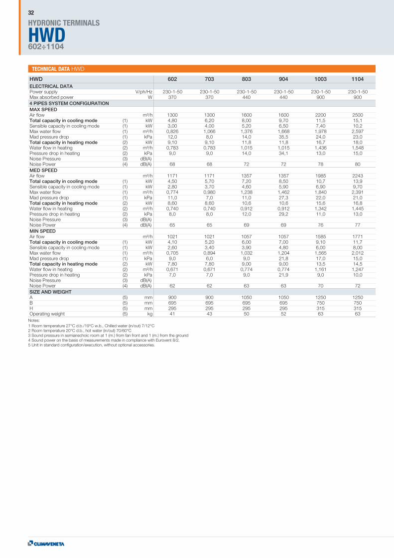
HWD 602 703 803 904 1003 1104ELECTRICAL DATAPower supply V/ph/Hz 230-1-50 230-1-50 230-1-50 230-1-50 230-1-50 230-1-50Max absorbed power W 370 370 440 440 900 9004 PIPES SYSTEM CONFIGURATIONMAX SPEEDAir flow 1300 1300 1600 1600 2200 2500Total capacity in cooling mode (1) kW 4,80 6,20 8,00 9,70 11,5 15,1Sensible capacity in cooling mode (1) kW 3,00 4,00 5,20 6,50 7,40 10,2Max water flow (1) 0,826 1,066 1,376 1,668 1,978 2,597Mad pressure drop (1) kPa 12,0 8,0 14,0 35,5 24,0 23,0Total capacity in heating mode (2) kW 9,10 9,10 11,8 11,8 16,7 18,0Water flow in heating (2) 0,783 0,783 1,015 1,015 1,436 1,548Pressure drop in heating (2) kPa 9,0 9,0 14,0 34,1 13,0 15,0Noise Pressure (3) dB(A)Noise Power (4) dB(A) 68 68 72 72 78 80MED SPEEDAir flow 1171 1171 1357 1357 1985 2243Total capacity in cooling mode (1) kW 4,50 5,70 7,20 8,50 10,7 13,9Sensible capacity in cooling mode (1) kW 2,80 3,70 4,60 5,90 6,90 9,70Max water flow (1) 0,774 0,980 1,238 1,462 1,840 2,391Mad pressure drop (1) kPa 11,0 7,0 11,0 27,3 22,0 21,0Total capacity in heating mode (2) kW 8,60 8,60 10,6 10,6 15,6 16,8Water flow in heating (2) 0,740 0,740 0,912 0,912 1,342 1,445Pressure drop in heating (2) kPa 8,0 8,0 12,0 29,2 11,0 13,0Noise Pressure (3) dB(A)Noise Power (4) dB(A) 65 65 69 69 76 77MIN SPEEDAir flow 1021 1021 1057 1057 1585 1771Total capacity in cooling mode (1) kW 4,10 5,20 6,00 7,00 9,10 11,7Sensible capacity in cooling mode (1) kW 2,60 3,40 3,90 4,80 6,00 8,00Max water flow (1) 0,705 0,894 1,032 1,204 1,565 2,012Mad pressure drop (1) kPa 9,0 6,0 9,0 21,8 17,0 15,0Total capacity in heating mode (2) kW 7,80 7,80 9,00 9,00 13,5 14,5Water flow in heating (2) 0,671 0,671 0,774 0,774 1,161 1,247Pressure drop in heating (2) kPa 7,0 7,0 9,0 21,9 9,0 10,0Noise Pressure (3) dB(A)Noise Power (4) dB(A) 62 62 63 63 70 72SIZE AND WEIGHTA (5) mm 900 900 1050 1050 1250 1250B (5) mm 695 695 695 695 750 750H (5) mm 295 295 295 295 315 315Operating weight (5) kg 41 43 50 52 63 63
Notes:1 Room temperature 27°C d.b./19°C w.b., Chilled water (in/out) 7/12°C2 Room temperature 20°C d.b., hot water (in/out) 70/60°C3 Sound pressure in semianechoic room at 1 (m.) from fan front and 1 (m.) from the ground4 Sound power on the basis of measurements made in compliance with Eurovent 8/2.5 Unit in standard configuration/execution, without optional accessories.

33
CONTROLLER4 PIPES
4P
2 PIPES
2P
A B
H
HWD HPHYDRONIC TERMINALS
0071÷0121
34
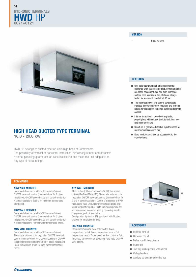
HIGH HEAD DUCTED TYPE TERMINAL16,8 - 29,8 kW
HWD HP belongs to ducted type fan-coils high head of Climaveneta.The possibility of vertical or horizontal installation, airflow adjustment and attractiveexternal panelling guarantees an ease installation and make the unit adaptable toany type of surroundings.
- base version
Unit coils guarantee high efficiency thermalexchange with low pressure drop. Finned unit coilsare made of copper tubes and high exchangesurface area aluminium fins. Coils are alwaystested for leaks with dried air at 30 bar;
The electrical power and control switchboardincludes electronic air flow regulator and terminalblocks for connection to power supply and remotecontrol;
Internal insulation in closed cell expandedpolyethylene with suitable thick to limit heat lossand noise emission;
Structure in galvanised steel of high thickness formaximum resistance to rust;
Extra modules available as accessories to thestandard unit;
NSW WALL MOUNTEDFan speed slider, mode slider (OFF/summer/winter).ON/OFF valve unit control (summer/winter for 2 pipesinstallation), ON/OFF second valve unit control (winter for4 pipes installation). Setting for minimum temperaturethermostat.
PSW WALL MOUNTEDFan speed slider, mode slider (OFF/summer/winter).ON/OFF valve unit control (summer/winter for 2 pipesinstallation), ON/OFF second valve unit control (winter for4 pipes installation). Remote water temperature probe.
MTW WALL MOUNTEDFan speed slider, mode slider (OFF/summer/winter).Thermostat with set point regulation. ON/OFF valve unitcontrol (summer/winter for 2 pipes installation), ON/OFFsecond valve unit control (winter for 4 pipes installation).Room temperature probe. Remote water temperatureprobe.
ATW WALL MOUNTEDMode button (OFF/summer/winter/AUTO), fan speedbutton (Max/Med/Min/AUTO). Thermostat with set pointregulation. ON/OFF valve unit control (summer/winter for2 and 4 pipes installation). Control of traditional or PWMmodulating valve units. Room temperature probe andwater temperature probe. Digital input configurable as:window contact, economy, heating or cooling remotechangeover, periodic ventilation.Configuration dip switch. TTL serial port with Modbusprotocol for installation in BMS.
PCE WALL-MOUNTEDOff/summer/winter/auto selector switch. Roomtemperature control. Room temperature sensor. Coiltemperature sensor. Three speed air flow control + Auto.Automatic summer/winter switching. Automatic ON/OFFvalve control.
Interface SPB Kit
Hot water coil kit
Delivery and intake plenum
Intake grill
Two way intake plenum with air lock
Ceiling brackets
Auxiliary condensate collecting tray
COMMANDS
VERSION
FEATURES
ACCESSORY

HWDTECHNICAL DATA HWD HP
35
CONTROLLER4 PIPES
4P
2 PIPES
2P
HWD HP 071 091 101 121ELECTRICAL DATAPower supply V/ph/Hz 230V~50Hz 230V~50Hz 230V~50Hz 230V~50HzMax absorbed power W 1 1 2 22 PIPES SYSTEM CONFIGURATIONMAX SPEEDAir flow m³/h 3200 3200 4400 5000Total capacity in cooling mode (1) kW 16,8 20,1 23,4 29,8Sensible capacity in cooling mode (1) kW 12,3 14,4 17,3 21,7Max water flow (1) m³/h 2,890 3,440 4,020 5,100Mad pressure drop (1) kPa 24,0 22,0 14,0 11,9Total capacity in heating mode (2) kW 16,3 19,6 23,0 29,8Water flow in heating (2) m³/h 2,890 3,440 4,020 5,100Pressure drop in heating (2) kPa 21,1 19,3 12,3 10,5Noise Pressure (3) dB(A) 60 60 66 69Noise Power (4) dB(A)SIZE AND WEIGHTA (5) mm 1300 1300 1500 1500B (5) mm 1119 1119 1349 1349H (5) mm 510 510 625 625Operating weight (5) kg 121 124 145 149
Notes:1 Room temperature 27°C d.b./19.5 °C w.b., Chilled water (in/out) 7/12°C2 Room temperature 20°C d.b., hot water (in/out) 45/40°C3 Sound pressure at 1 (m.) from fan front4 Sound power on the basis of measurements made in compliance with Eurovent 8/2.5 Unit in standard configuration/execution, without optional accessories.
HWD HP 0071 0091 0101 0121ELECTRICAL DATAPower supply V/ph/Hz 230V~50Hz 230V~50Hz 230V~50Hz 230V~50HzMax absorbed power W 1 1 2 24 PIPES SYSTEM CONFIGURATIONMAX SPEEDAir flow m³/h 3200 3200 4400 5000Total capacity in cooling mode (1) kW 16,8 20,1 23,4 29,8Sensible capacity in cooling mode (1) kW 12,3 14,4 17,3 21,7Max water flow (1) m³/h 2,890 3,440 4,020 5,100Mad pressure drop (1) kPa 24,0 22,0 14,0 11,9Total capacity in heating mode (2) kW 25,0 25,0 36,0 39,0Water flow in heating (2) m³/h 2,200 2,200 3,200 3,400Pressure drop in heating (2) kPa 13,0 13,0 19,0 22,0Noise Pressure (3) dB(A) 60 60 66 69Noise Power (4) dB(A)SIZE AND WEIGHTA (5) mm 1300 1300 1500 1500B (5) mm 1119 1119 1349 1349H (5) mm 510 510 625 625Operating weight (5) kg 121 124 145 149
Notes:1 Room temperature 27°C d.b./19.5 °C w.b., Chilled water (in/out) 7/12°C2 Room temperature 20°C d.b., hot water (in/out) 70/60°C3 Sound pressure at 1 (m.) from fan front4 Sound power on the basis of measurements made in compliance with Eurovent 8/2.5 Unit in standard configuration/execution, without optional accessories.

A B
H
HRDHYDRONIC TERMINALS
021÷151
36
HEAT RECUPERATOR UNIT290-4000 m3/h
HRD heat recuperator units for residential and commercial application allow maximum roomcomfort and energy saving. In modern systems is becoming necessary to create forcedventilation, which involves air conditioned expelling; thereby consuming more energy andconsequenting increasing costs. HRD heat recuperators have obviated such as problemsusing an aluminium static recovery unit that saves more than 50% energy, otherwise be lostwith expelled stale air. HRD can be integrated in traditional systems with fan coils, chillersand radiators and may operate both in summer and winter. These units are recommended forsuspended ceiling installation and may be suitably ducted to allow the fresh air intake anddistribution.
- base version
Removable aluzink plate side panels;
Panels insulated and soundproofed withpolyethylene/polyester with average thickness of10 mm (mod. HRD 0021-0051) and 20 mm for theother models;
High efficiency aluminium plate static type heatrecovery units, with airflow separated by specialseals;
UE3 efficiency air filters, which may be easilyremoved from any side of the unit (bottom, side,top) for periodic cleaning;
Fan casings on vibration-isolation mountings;
Double inlet centrifugal fans for fresh air intake andused air extraction, which may be removed fromany side of the unit for periodic maintenance;
Multi speed directly coupled electric motor;
A terminal block with a relay board is fitted on theunit to aid electrical connections and fan control;
Stainless steel condensate collecting tray, withcondensate drain directed downwards;
NSW WALL MOUNTEDFan speed slider, mode slider (OFF/summer/winter).ON/OFF valve unit control (summer/winter for 2 pipesinstallation), ON/OFF second valve unit control (winterfor 4 pipes installation). Setting for minimumtemperature thermostat.
MTW WALL MOUNTEDFan speed slider, mode slider (OFF/summer/winter).Thermostat with set point regulation. ON/OFF valve unitcontrol (summer/winter for 2 pipes installation), ON/OFFsecond valve unit control (winter for 4 pipesinstallation). Room temperature probe. Remote watertemperature probe.
ATW WALL MOUNTEDMode button (OFF/summer/winter/AUTO), fan speedbutton (Max/Med/Min/AUTO). Thermostat with set pointregulation. ON/OFF valve unit control (summer/winterfor 2 and 4 pipes installation). Control of traditional orPWM modulating valve units. Room temperature probeand water temperature probe. Digital input configurableas: window contact, economy, heating or coolingremote changeover, periodic ventilation. Configurationdip switch. TTL serial port with Modbus protocol forinstallation in BMS.
PCE WALL-MOUNTEDOff/summer/winter/auto selector switch. Roomtemperature control. Room temperature sensor. Coiltemperature sensor. Three speed air flow control +Auto. Automatic summer/winter switching. AutomaticON/OFF valve control.
Interface SPB Kit
Hot water coil kit
Cool water coil kit
Heating element kit
COMMANDS
VERSION
FEATURES
ACCESSORY
37
CONTROLLERPLATE
HWDTECHNICAL DATA HRD
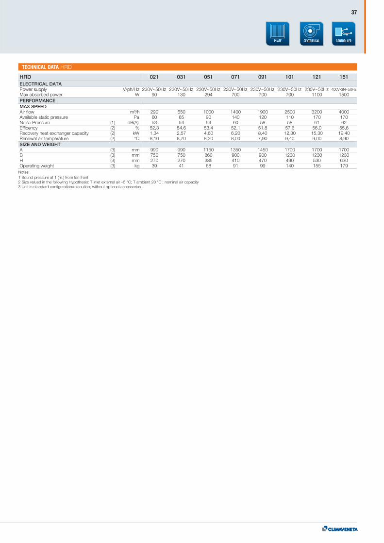
HRD 021 031 051 071 091 101 121 151ELECTRICAL DATAPower supply V/ph/Hz 230V~50Hz 230V~50Hz 230V~50Hz 230V~50Hz 230V~50Hz 230V~50Hz 230V~50Hz 400V-3N~50Hz
Max absorbed power W 90 130 294 700 700 700 1100 1500PERFORMANCEMAX SPEEDAir flow m³/h 290 550 1000 1400 1900 2500 3200 4000Available static pressure Pa 60 65 90 140 120 110 170 170Noise Pressure (1) dB(A) 53 54 54 60 58 58 61 62Efficency (2) % 52,3 54,6 53,4 52,1 51,8 57,6 56,0 55,6Recovery heat exchanger capacity (2) kW 1,34 2,57 4,60 6,20 8,40 12,30 15,30 19,40Renewal air temperature (2) °C 8,10 8,70 8,30 8,00 7,90 9,40 9,00 8,90SIZE AND WEIGHTA (3) mm 990 990 1150 1350 1450 1700 1700 1700B (3) mm 750 750 860 900 900 1230 1230 1230H (3) mm 270 270 385 410 470 490 530 630Operating weight (3) kg 39 41 68 91 99 140 155 179
Notes:1 Sound pressure at 1 (m.) from fan front2 Size valued in the following Hypothesis: T inlet external air –5 °C; T ambient 20 °C ; nominal air capacity3 Unit in standard configuration/execution, without optional accessories.
a-CHDHYDRONIC TERMINALS
0606 - 2209
38
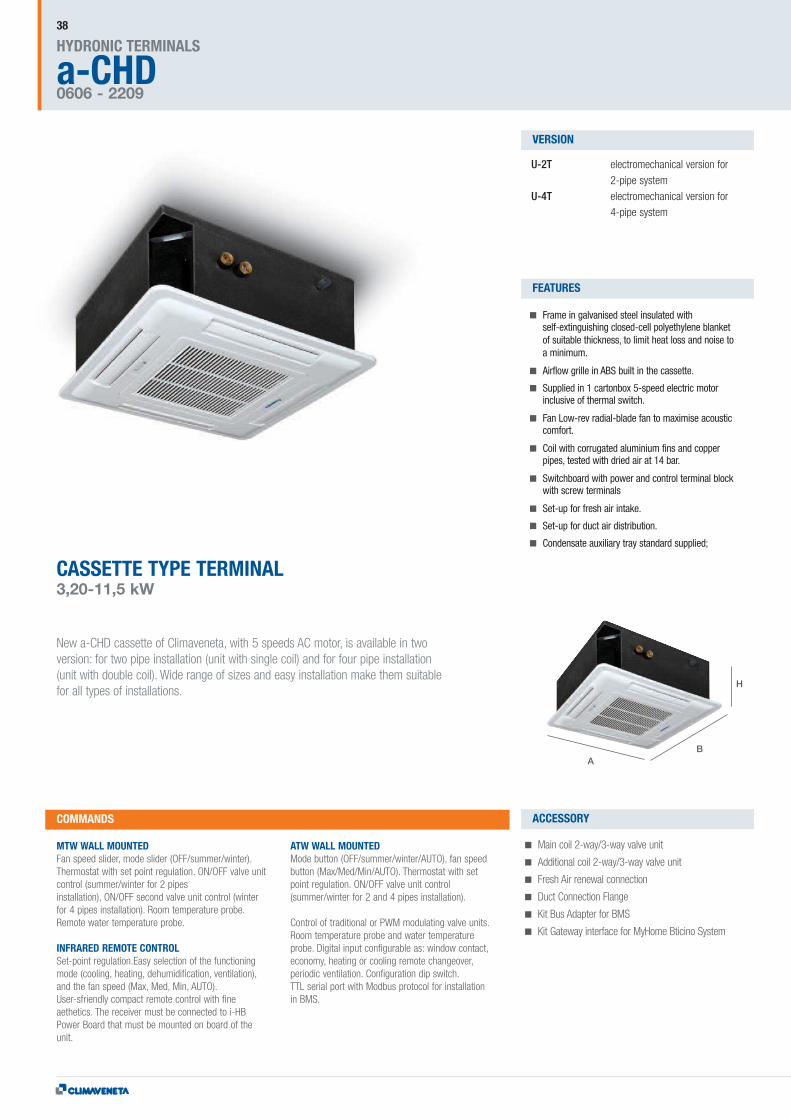
CASSETTE TYPE TERMINAL3,20-11,5 kW
New a-CHD cassette of Climaveneta, with 5 speeds AC motor, is available in twoversion: for two pipe installation (unit with single coil) and for four pipe installation(unit with double coil). Wide range of sizes and easy installation make them suitablefor all types of installations.
U-2T electromechanical version for2-pipe system
U-4T electromechanical version for4-pipe system
Frame in galvanised steel insulated withself-extinguishing closed-cell polyethylene blanketof suitable thickness, to limit heat loss and noise toa minimum.
Airflow grille in ABS built in the cassette.
Supplied in 1 cartonbox 5-speed electric motorinclusive of thermal switch.
Fan Low-rev radial-blade fan to maximise acousticcomfort.
Coil with corrugated aluminium fins and copperpipes, tested with dried air at 14 bar.
Switchboard with power and control terminal blockwith screw terminals
Set-up for fresh air intake.
Set-up for duct air distribution.
Condensate auxiliary tray standard supplied;
MTW WALL MOUNTEDFan speed slider, mode slider (OFF/summer/winter).Thermostat with set point regulation. ON/OFF valve unitcontrol (summer/winter for 2 pipesinstallation), ON/OFF second valve unit control (winterfor 4 pipes installation). Room temperature probe.Remote water temperature probe.
INFRARED REMOTE CONTROLSet-point regulation.Easy selection of the functioningmode (cooling, heating, dehumidification, ventilation),and the fan speed (Max, Med, Min, AUTO).User-sfriendly compact remote control with fineaethetics. The receiver must be connected to i-HBPower Board that must be mounted on board of theunit.
ATW WALL MOUNTEDMode button (OFF/summer/winter/AUTO), fan speedbutton (Max/Med/Min/AUTO). Thermostat with setpoint regulation. ON/OFF valve unit control(summer/winter for 2 and 4 pipes installation).
Control of traditional or PWM modulating valve units.Room temperature probe and water temperatureprobe. Digital input configurable as: window contact,economy, heating or cooling remote changeover,periodic ventilation. Configuration dip switch.TTL serial port with Modbus protocol for installationin BMS.
Main coil 2-way/3-way valve unit
Additional coil 2-way/3-way valve unit
Fresh Air renewal connection
Duct Connection Flange
Kit Bus Adapter for BMS
Kit Gateway interface for MyHome Bticino System
COMMANDS
VERSION
FEATURES
ACCESSORY
AB
H
39
CONTROLLER4 PIPES
4P
2 PIPES
2P
HWDTECHNICAL DATA a-CHD
i-CHDHYDRONIC TERMINALS
706-2209
40
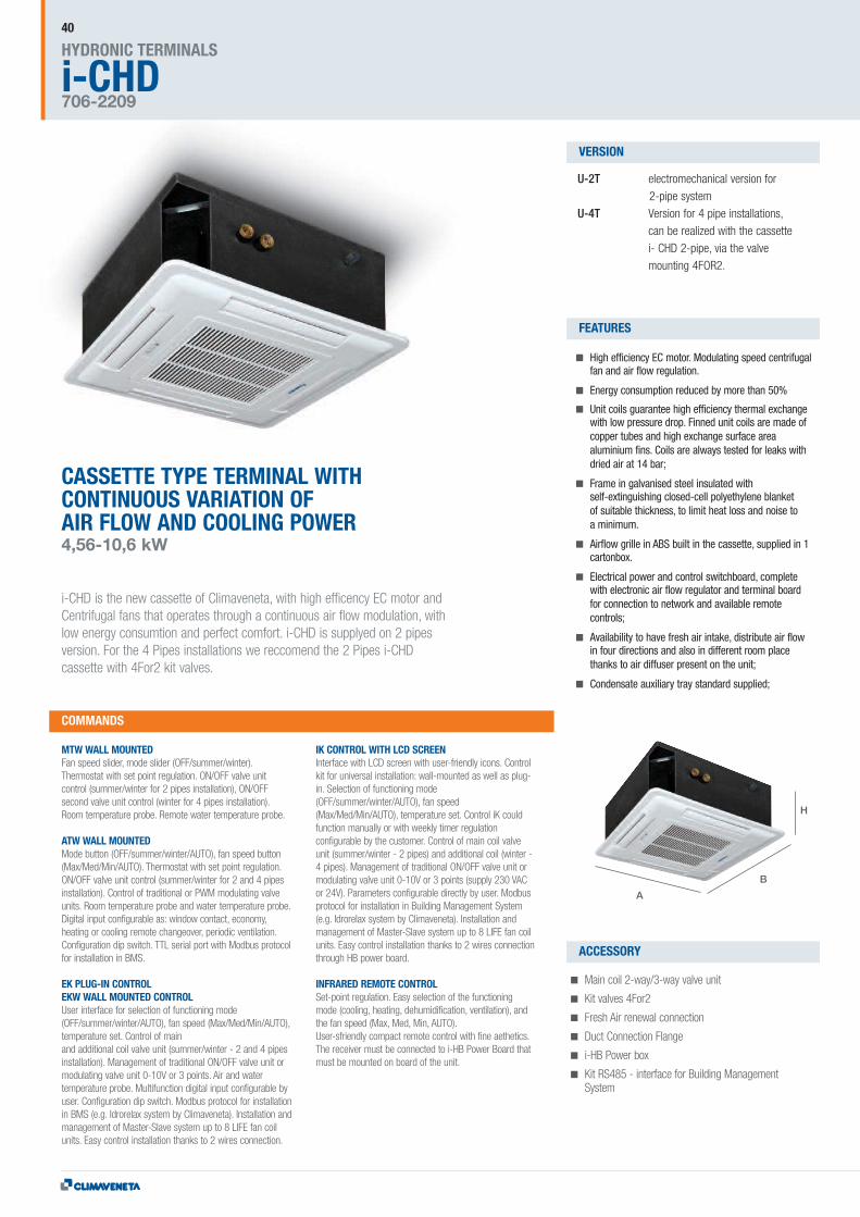
CASSETTE TYPE TERMINAL WITHCONTINUOUS VARIATION OFAIR FLOW AND COOLING POWER4,56-10,6 kW
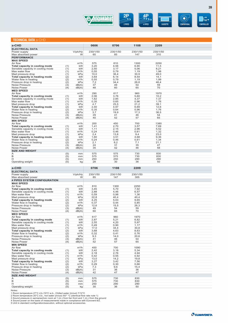
i-CHD is the new cassette of Climaveneta, with high efficency EC motor andCentrifugal fans that operates through a continuous air flow modulation, withlow energy consumtion and perfect comfort. i-CHD is supplyed on 2 pipesversion. For the 4 Pipes installations we reccomend the 2 Pipes i-CHDcassette with 4For2 kit valves.
U-2T electromechanical version for2-pipe system
U-4T Version for 4 pipe installations,can be realized with the cassettei- CHD 2-pipe, via the valvemounting 4FOR2.
High efficiency EC motor. Modulating speed centrifugalfan and air flow regulation.
Energy consumption reduced by more than 50%
Unit coils guarantee high efficiency thermal exchangewith low pressure drop. Finned unit coils are made ofcopper tubes and high exchange surface areaaluminium fins. Coils are always tested for leaks withdried air at 14 bar;
Frame in galvanised steel insulated withself-extinguishing closed-cell polyethylene blanketof suitable thickness, to limit heat loss and noise toa minimum.
Airflow grille in ABS built in the cassette, supplied in 1cartonbox.
Electrical power and control switchboard, completewith electronic air flow regulator and terminal boardfor connection to network and available remotecontrols;
Availability to have fresh air intake, distribute air flowin four directions and also in different room placethanks to air diffuser present on the unit;
Condensate auxiliary tray standard supplied;
MTW WALL MOUNTEDFan speed slider, mode slider (OFF/summer/winter).Thermostat with set point regulation. ON/OFF valve unitcontrol (summer/winter for 2 pipes installation), ON/OFFsecond valve unit control (winter for 4 pipes installation).Room temperature probe. Remote water temperature probe.
ATW WALL MOUNTEDMode button (OFF/summer/winter/AUTO), fan speed button(Max/Med/Min/AUTO). Thermostat with set point regulation.ON/OFF valve unit control (summer/winter for 2 and 4 pipesinstallation). Control of traditional or PWM modulating valveunits. Room temperature probe and water temperature probe.Digital input configurable as: window contact, economy,heating or cooling remote changeover, periodic ventilation.Configuration dip switch. TTL serial port with Modbus protocolfor installation in BMS.
EK PLUG-IN CONTROLEKW WALL MOUNTED CONTROLUser interface for selection of functioning mode(OFF/summer/winter/AUTO), fan speed (Max/Med/Min/AUTO),temperature set. Control of mainand additional coil valve unit (summer/winter - 2 and 4 pipesinstallation). Management of traditional ON/OFF valve unit ormodulating valve unit 0-10V or 3 points. Air and watertemperature probe. Multifunction digital input configurable byuser. Configuration dip switch. Modbus protocol for installationin BMS (e.g. Idrorelax system by Climaveneta). Installation andmanagement of Master-Slave system up to 8 LIFE fan coilunits. Easy control installation thanks to 2 wires connection.
IK CONTROL WITH LCD SCREENInterface with LCD screen with user-friendly icons. Controlkit for universal installation: wall-mounted as well as plug-in. Selection of functioning mode(OFF/summer/winter/AUTO), fan speed(Max/Med/Min/AUTO), temperature set. Control iK couldfunction manually or with weekly timer regulationconfigurable by the customer. Control of main coil valveunit (summer/winter - 2 pipes) and additional coil (winter -4 pipes). Management of traditional ON/OFF valve unit ormodulating valve unit 0-10V or 3 points (supply 230 VACor 24V). Parameters configurable directly by user. Modbusprotocol for installation in Building Management System(e.g. Idrorelax system by Climaveneta). Installation andmanagement of Master-Slave system up to 8 LIFE fan coilunits. Easy control installation thanks to 2 wires connectionthrough HB power board.
INFRARED REMOTE CONTROLSet-point regulation. Easy selection of the functioningmode (cooling, heating, dehumidification, ventilation), andthe fan speed (Max, Med, Min, AUTO).User-sfriendly compact remote control with fine aethetics.The receiver must be connected to i-HB Power Board thatmust be mounted on board of the unit.
Main coil 2-way/3-way valve unit
Kit valves 4For2
Fresh Air renewal connection
Duct Connection Flange
i-HB Power box
Kit RS485 - interface for Building ManagementSystem
COMMANDS
VERSION
FEATURES
ACCESSORY
A
B
H
41
CONTROLLER4 PIPES
4P
2 PIPES
2P
HWDTECHNICAL DATA i-CHD

CONTROLLERSHYDRONIC TERMINALS42
THE WIDE RANGE OF AVAILABLEWALL-MOUNTED AND BUILT-INCONTROLLERS, ALLOWS A USER-FRIENDLY AND COMPLETEREGULATION OF ALL THE FUNCTIONS,AND AN EASY INTEGRATION WITHHOME AUTOMATION, CENTRALIZATION,BUILDING MANAGEMENT SYSTEMS.
NS plug-inNSW wall mounted
Fan speed slider, mode slider,minimum temperaturethermostat and command ofon/off valves
AT plug-inATW wall mounted
Room thermostat, manual-and automatic regulation offan, manualand automaticmode change-over, room-and minimum temperatureprobes and command ofon/off valves.Multifunction digital contact.Configuration dip switch.
Infrared Remote Control
Set-point regulation.Easy selection of the functioningmode (cooling, heating,dehumidification, ventilation),and the fan speed (Max, Med,Min, AUTO). User-sfriendlycompact remote control with fineaethetics. The receiver must beconnected to i-HB Power Boardthat must be mounted on boardof the unit.
PS plug-inPSW wall mounted
Fan speed slider, modeslider, minimumtemperature probe andregulation of on/off valves
MT plug-inMTW wall mounted
Room thermostat, fanspeed slider, mode slider,room- and minimumtemperature probes andregulation of on/off valves
EK plug-inEKW wall mounted
Room thermostat, manualandautomatic regulation of fan,manual- and automaticmode, change-over, roomandminimum temperatureprobes, regulation of electricheater, valves (on/off ormodulating), serialconnection for mini-networkand integration into BMSorIdrorelax systems
iK universal
Electronic control with LCDdisplay, room thermostat,manual and automaticregulation of fan, manual- andautomatic mode change-over,room and minimumtemperature probes, regulationof electric heater, valves (on/offor modulating), 0-10 V outputfor the regulation of the energy-saving brushless fan motor,serial connection for mini-network and integration intoBMS or Idrorelax systems
NotesRefer to the dedicated product's pages for more information about compatibility between the controllers and the single fan coil.The iK, EK, EKW controllers installed with a-LIFE and a-LIFE HP have to be combined with the 'HB LIFE' power board (cod. 7349051500).
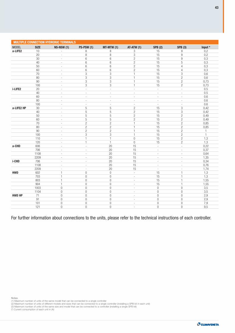
MULTIPLE CONNECTION HYDRONIC TERMINALSMODEL SIZE NS-NSW (1) PS-PSW (1) MT-MTW (1) AT-ATW (1) SPB (2) SPB (3) Input *a-LIFE2 10 - 8 8 3 15 9 0,2
20 - 8 8 3 15 9 0,230 - 6 6 2 15 9 0,340 - 6 6 2 15 5 0,350 - 6 6 2 15 4 0,360 - 6 6 2 15 4 0,370 - 3 3 1 15 3 0,680 - 3 3 1 15 2 0,690 - 3 3 1 15 2 0,73100 - 3 3 1 15 2 0,73
i-LIFE2 20 - - - - - - 0.540 - - - - - - 0.560 - - - - - - 0.680 - - - - - - 0.6100 - - - - - - 0.6
a-LIFE2 HP 30 - 5 5 2 15 3 0,4240 - 5 5 2 15 3 0,4250 - 5 5 2 15 2 0,4960 - 5 5 2 15 2 0,4970 - 2 2 1 15 2 0,8580 - 2 2 1 15 2 0,8590 - 2 2 1 15 2 1100 - 3 3 1 15 2 1110 - 1 1 0 15 2 1,3120 - 1 1 0 15 2 1,3
a-CHD 606 - - 20 15 - - 0,22706 - - 20 15 - - 0,371108 - - 20 15 - - 0,642209 - - 20 15 - - 1,35
i-CHD 706 - - 20 15 - - 0,341108 - - 20 15 - - 0,762209 - - 20 15 - - 1,74
HWD 602 1 0 0 - 15 1 1,3703 1 0 0 - 15 1 1,3803 1 0 0 - 15 1 1,55904 1 0 0 - 15 1 1,551003 0 0 0 - 0 0 3,51104 0 0 0 - 0 0 3,5
HWD HP 71 0 0 0 - 0 0 2,991 0 0 0 - 0 0 2,9101 0 0 0 - 0 0 7,9121 0 0 0 - 0 0 9,5
Notes(1) Maximum number of units of the same model that can be connected to a single controller(2) Maximum number of units of different models and sizes that can be connected to a single controller (installing a SPB kit in each unit)(3) Maximum number of units of the same size and model that can be connected to a controller (installing a single SPB kit)(*) Current consumption of each unit in (A)
43
For further information about connections to the units, please refer to the technical instructions of each controller.
HYDR
ONIC
TER
MIN
ALS_
07-2
014_
ENG_
00


![Pulsar Installation Guide · or control fan speed with a full range dimmer switch. [Using a full range dimmer switch to control fan speed will cause a loud humming noise from fan.]](https://img.pdfslide.net/doc/110x75/5f5c81e48acfee02dd0871c1/pulsar-installation-guide-or-control-fan-speed-with-a-full-range-dimmer-switch.jpg)