Embed Size (px)
Citation preview
May 2010
© 2010 Fairchild Semiconductor Corporation www.fairchildsemi.com FAN5622 / FAN5624 / FAN5626 • Rev. 1.0.1
FAN
5622/24/26 — Linear LED
Drivers w
ith Single-Wire D
igital Interface
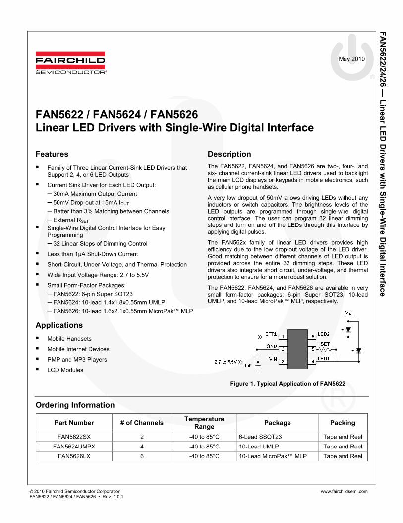
FAN5622 / FAN5624 / FAN5626 Linear LED Drivers with Single-Wire Digital Interface
Features Family of Three Linear Current-Sink LED Drivers that
Support 2, 4, or 6 LED Outputs
Current Sink Driver for Each LED Output: – 30mA Maximum Output Current – 50mV Drop-out at 15mA IOUT – Better than 3% Matching between Channels – External RSET
Single-Wire Digital Control Interface for Easy Programming – 32 Linear Steps of Dimming Control
Less than 1µA Shut-Down Current
Short-Circuit, Under-Voltage, and Thermal Protection
Wide Input Voltage Range: 2.7 to 5.5V
Small Form-Factor Packages: – FAN5622: 6-pin Super SOT23 – FAN5624: 10-lead 1.4x1.8x0.55mm UMLP – FAN5626: 10-lead 1.6x2.1x0.55mm MicroPak™ MLP
Applications Mobile Handsets
Mobile Internet Devices
PMP and MP3 Players
LCD Modules
Description The FAN5622, FAN5624, and FAN5626 are two-, four-, and six- channel current-sink linear LED drivers used to backlight the main LCD displays or keypads in mobile electronics, such as cellular phone handsets.
A very low dropout of 50mV allows driving LEDs without any inductors or switch capacitors. The brightness levels of the LED outputs are programmed through single-wire digital control interface. The user can program 32 linear dimming steps and turn on and off the LEDs through this interface by applying digital pulses.
The FAN562x family of linear LED drivers provides high efficiency due to the low drop-out voltage of the LED driver. Good matching between different channels of LED output is provided across the entire 32 dimming steps. These LED drivers also integrate short circuit, under-voltage, and thermal protection to ensure for a more robust solution.
The FAN5622, FAN5624, and FAN5626 are available in very small form-factor packages: 6-pin Super SOT23, 10-lead UMLP, and 10-lead MicroPak™ MLP, respectively.
Figure 1. Typical Application of FAN5622
Ordering Information
Part Number # of Channels Temperature Range Package Packing
FAN5622SX 2 -40 to 85°C 6-Lead SSOT23 Tape and Reel FAN5624UMPX 4 -40 to 85°C 10-Lead UMLP Tape and Reel
FAN5626LX 6 -40 to 85°C 10-Lead MicroPak™ MLP Tape and Reel
© 2010 Fairchild Semiconductor Corporation www.fairchildsemi.com FAN5622 / FAN5624 / FAN5626 • Rev. 1.0.1 2
FAN
5622/24/26 — Linear LED
Drivers w
ith Single-Wire D
igital Interface
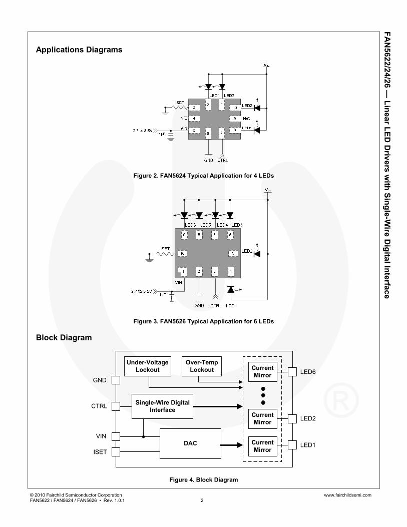
Applications Diagrams
Figure 2. FAN5624 Typical Application for 4 LEDs
Figure 3. FAN5626 Typical Application for 6 LEDs
Block Diagram
CurrentMirror
CurrentMirror
CurrentMirror
Under-VoltageLockout
Over-TempLockout
DAC
Single-Wire DigitalInterfaceCTRL
VIN
ISETLED1
LED2
LED6GND
Figure 4. Block Diagram
© 2010 Fairchild Semiconductor Corporation www.fairchildsemi.com FAN5622 / FAN5624 / FAN5626 • Rev. 1.0.1 3
FAN
5622/24/26 — Linear LED
Drivers w
ith Single-Wire D
igital Interface
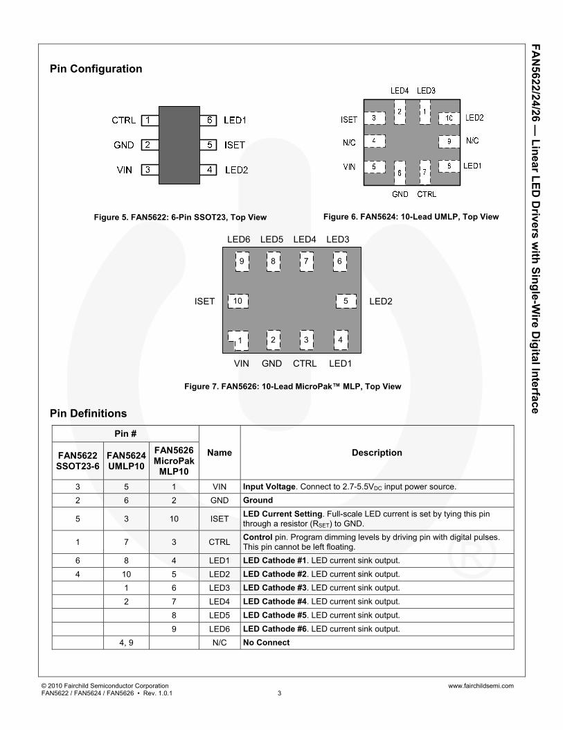
Pin Configuration
Figure 5. FAN5622: 6-Pin SSOT23, Top View
Figure 6. FAN5624: 10-Lead UMLP, Top View
432
9 678
10 5
VIN
ISET
LED6 LED5 LED4 LED3
LED2
LED1CTRLGND
1
Figure 7. FAN5626: 10-Lead MicroPak™ MLP, Top View
Pin Definitions
Pin #
Name Description FAN5622 SSOT23-6
FAN5624 UMLP10
FAN5626 MicroPak
MLP10 3 5 1 VIN Input Voltage. Connect to 2.7-5.5VDC input power source.
2 6 2 GND Ground
5 3 10 ISET LED Current Setting. Full-scale LED current is set by tying this pin through a resistor (RSET) to GND.
1 7 3 CTRL Control pin. Program dimming levels by driving pin with digital pulses. This pin cannot be left floating.
6 8 4 LED1 LED Cathode #1. LED current sink output.
4 10 5 LED2 LED Cathode #2. LED current sink output. 1 6 LED3 LED Cathode #3. LED current sink output. 2 7 LED4 LED Cathode #4. LED current sink output. 8 LED5 LED Cathode #5. LED current sink output. 9 LED6 LED Cathode #6. LED current sink output. 4, 9 N/C No Connect

© 2010 Fairchild Semiconductor Corporation www.fairchildsemi.com FAN5622 / FAN5624 / FAN5626 • Rev. 1.0.1 4
FAN
5622/24/26 — Linear LED
Drivers w
ith Single-Wire D
igital Interface
Absolute Maximum Ratings Stresses exceeding the absolute maximum ratings may damage the device. The device may not function or be operable above the recommended operating conditions and stressing the parts to these levels is not recommended. In addition, extended exposure to stresses above the recommended operating conditions may affect device reliability. The absolute maximum ratings are stress ratings only.
Symbol Parameter Min. Max. Units
VCC VIN Pin -0.3 6.0 V
Other Pins(1) -0.3 VIN + 0.3 V
ESD Electrostatic Discharge Protection Level Human Body Model per JESD22-A114 3.0 kV Charged Device Model per JESD22-C101 1.5 kV
TJ Junction Temperature –40 +150 °C TSTG Storage Temperature –65 +150 °C TL Lead Soldering Temperature, 10 Seconds +260 °C
Note: 1. Lesser of 6.0V or VIN+0.3V.
Recommended Operating Conditions The Recommended Operating Conditions table defines the conditions for actual device operation. Recommended operating conditions are specified to ensure optimal performance to the datasheet specifications. Fairchild does not recommend exceeding them or designing to absolute maximum ratings.
Symbol Parameter Min. Max. UnitsVIN Power Supply Voltage Range 2.7 5.5 V TA Operating Ambient Temperature Range -40 +85 °C TJ Operating Junction Temperature Range -40 +125 °C
ILED(FS) Full-Scale LED Current 5 30 mA
Thermal Properties Junction-to-ambient thermal resistance is a function of application and board layout. This data is measured with boards in accordance to JEDEC standard JESD51. Special attention must be paid not to exceed junction temperature TJ(max) at a given ambient temperature TA.
Symbol Parameter Typical Units θJA_SSOT23-6 Junction-to-Ambient Thermal Resistance, SSOT23-6 Package 235 °C/W θJA_UMLP10 Junction-to-Ambient Thermal Resistance, UMLP10 Package(2) 287 °C/W
θJA_MicroPAK_MLP10 Junction-to-Ambient Thermal Resistance, MicroPak™ MLP10 package(3) 220 °C/W
Notes: 2. Recommended not to exceed 132mW of maximum power dissipation. 3. Recommended not to exceed 198mW of maximum power dissipation.

© 2010 Fairchild Semiconductor Corporation www.fairchildsemi.com FAN5622 / FAN5624 / FAN5626 • Rev. 1.0.1 5
FAN
5622/24/26 — Linear LED
Drivers w
ith Single-Wire D
igital Interface
Electrical Specifications VIN = 2.7V to 5.5V, RSET = 19.10kΩ, TA = -40°C to +85°C, Vf = 2.5V to [3.5V or VIN – 0.1V], whichever is smaller. Typical values are at TA = 25°C, VIN = 3.6V, and Vf= 3.2V.
Symbol Parameter Conditions Min. Typ. Max. Units Power Supplies
ISD Shutdown Supply Current VIN = 3.6V, CTRL = 0 0.3 1.0 µA
IIN Operating Supply Current FAN5622: VIN = 3.6V, ILED = 0mA 0.4 0.8 mA FAN5624: VIN = 3.6V, ILED = 0mA 0.6 1.0 mA FAN5626: VIN = 3.6V, ILED = 0mA 0.8 1.2 mA
IIH Control Pin Input Current CTRL = 1.8V 1 250 nA
VUVLO Under-Voltage Lockout Threshold
VIN Rising 2.50 2.70 V VIN Falling 2.10 2.30 2.50 V
Regulation IFS_LEDx (MAX) Full-Scale LED Output Current ILEDx = 30mA; x = 1 to 6 5 30 mA
ILED Absolute Current Accuracy
VIN=2.85V – 4.5V; VCATH =0.15 to (1.2V or VIN=2.55V, Whichever is Smaller); Full-Scale Current 5-30mA, TA = 25°C
-10 +10 %
ILED MATCH LED Current Matching(4) ILEDx = 15mA; V_LEDx=0.4V, TA = 25°C -3 +3 %
VISET ISET Drive Voltage 9.53kΩ ≤ RSET ≤ 56.2kΩ 1.20 V
IRATIO Current Mirror Ratio from ISET Pin 9.53kΩ ≤ RSET ≤ 56.2kΩ 240
∆IOUT_LOAD IOUT Load Regulation VIN = 3.6V, ILEDx = 15mA, LED VF = 2.7 to 3.5V, -3 +3 %
∆IOUT_LINE IOUT Line Regulation VIN = 2.7 to 4.8V, ILEDx = 15mA, VCATH = 0.5V -4 +4 %
VDROPOUT Dropout Voltage
VIN=3.6V; ILED = 15mA, -10% ILED Drop 50
mV VIN=3.6V; ILED = 30mA, -10% ILED Drop 60
TSD Thermal Shutdown Rising Temperature at Junction 150
°C Hysteresis 20
Logic Input (CTRL) VIH HIGH-Level Input Voltage 1.2 V VIL LOW-Level Input Voltage 0.4 V TLO CTRL LOW Time for Dimming VIN = 3.6V; See Figure 17 0.5 300 µs
THI Time Delay between Steps VIN = 3.6V; See Figure 17 0.5 µs
TON CTRL HIGH to Turn-On Delay VIN = 3.6V; See Figure 17 250 µs
TSD CTRL LOW, Shutdown Pulse Width
VIN = 3.6V; from Falling Edge of CTRL 1 ms
Note: 4. For the two, four, and six LED current sinks of FAN5622, FAN5624, and FAN5626 respectively; the following are
determined: the maximum sink current of the two, four, and six LED outputs (MAX); the minimum sink current of the two, four, and six outputs (MIN); and the average sink current (AVG). For all of the LED outputs, two matching numbers are calculated: (MAX-AVG)/ AVG and (AVG-MIN)/AVG. The largest number of the two (worst case) is considered the matching figure for the part. The matching figure for a given part is considered to be the highest matching figure of all LED outputs. The typical specification provided is the most likely norm of the matching figure for all parts.
© 2010 Fairchild Semiconductor Corporation www.fairchildsemi.com FAN5622 / FAN5624 / FAN5626 • Rev. 1.0.1 6
FAN
5622/24/26 — Linear LED
Drivers w
ith Single-Wire D
igital Interface
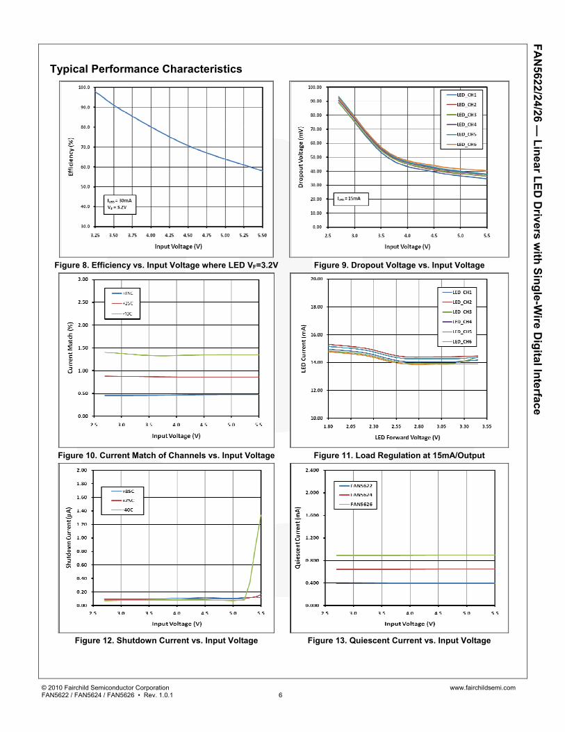
Typical Performance Characteristics
Figure 8. Efficiency vs. Input Voltage where LED VF=3.2V Figure 9. Dropout Voltage vs. Input Voltage
Figure 10. Current Match of Channels vs. Input Voltage Figure 11. Load Regulation at 15mA/Output
Figure 12. Shutdown Current vs. Input Voltage Figure 13. Quiescent Current vs. Input Voltage

© 2010 Fairchild Semiconductor Corporation www.fairchildsemi.com FAN5622 / FAN5624 / FAN5626 • Rev. 1.0.1 7
FAN
5622/24/26 — Linear LED
Drivers w
ith Single-Wire D
igital Interface
Typical Performance Characteristics
Figure 14. Startup Waveform for FAN5626 Figure 15. Shutdown Waveform for FAN5626
Figure 16. Dimming Operation
© 2010 Fairchild Semiconductor Corporation www.fairchildsemi.com FAN5622 / FAN5624 / FAN5626 • Rev. 1.0.1 8
FAN
5622/24/26 — Linear LED
Drivers w
ith Single-Wire D
igital Interface
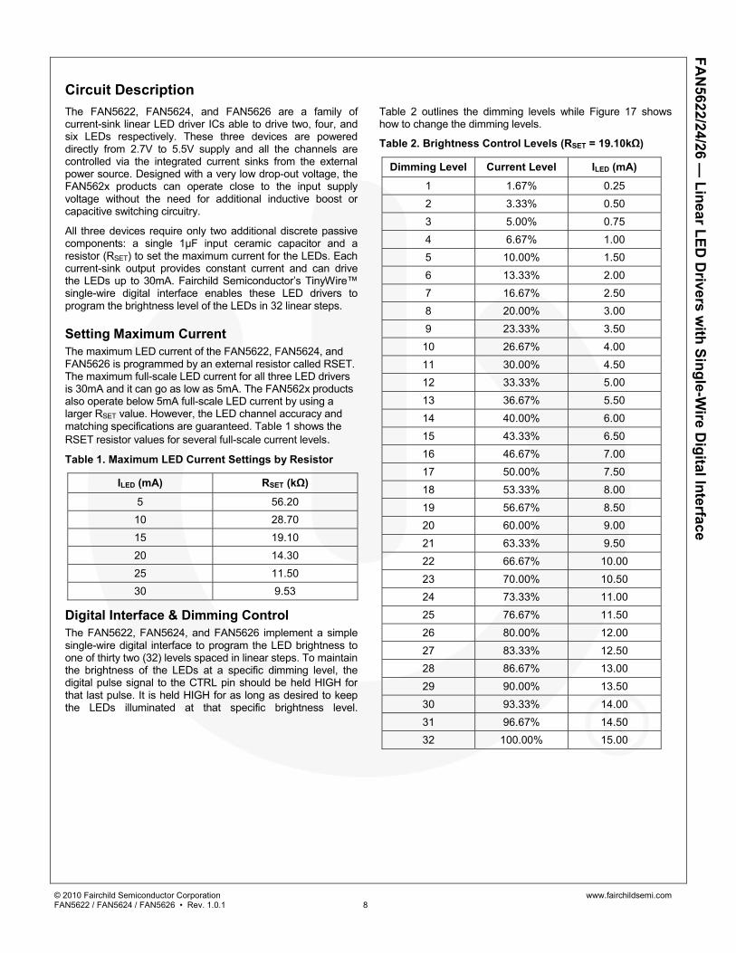
Circuit Description The FAN5622, FAN5624, and FAN5626 are a family of current-sink linear LED driver ICs able to drive two, four, and six LEDs respectively. These three devices are powered directly from 2.7V to 5.5V supply and all the channels are controlled via the integrated current sinks from the external power source. Designed with a very low drop-out voltage, the FAN562x products can operate close to the input supply voltage without the need for additional inductive boost or capacitive switching circuitry.
All three devices require only two additional discrete passive components: a single 1µF input ceramic capacitor and a resistor (RSET) to set the maximum current for the LEDs. Each current-sink output provides constant current and can drive the LEDs up to 30mA. Fairchild Semiconductor’s TinyWire™ single-wire digital interface enables these LED drivers to program the brightness level of the LEDs in 32 linear steps.
Setting Maximum Current The maximum LED current of the FAN5622, FAN5624, and FAN5626 is programmed by an external resistor called RSET. The maximum full-scale LED current for all three LED drivers is 30mA and it can go as low as 5mA. The FAN562x products also operate below 5mA full-scale LED current by using a larger RSET value. However, the LED channel accuracy and matching specifications are guaranteed. Table 1 shows the RSET resistor values for several full-scale current levels. Table 1. Maximum LED Current Settings by Resistor
ILED (mA) RSET (kΩ)
5 56.20 10 28.70 15 19.10 20 14.30 25 11.50 30 9.53
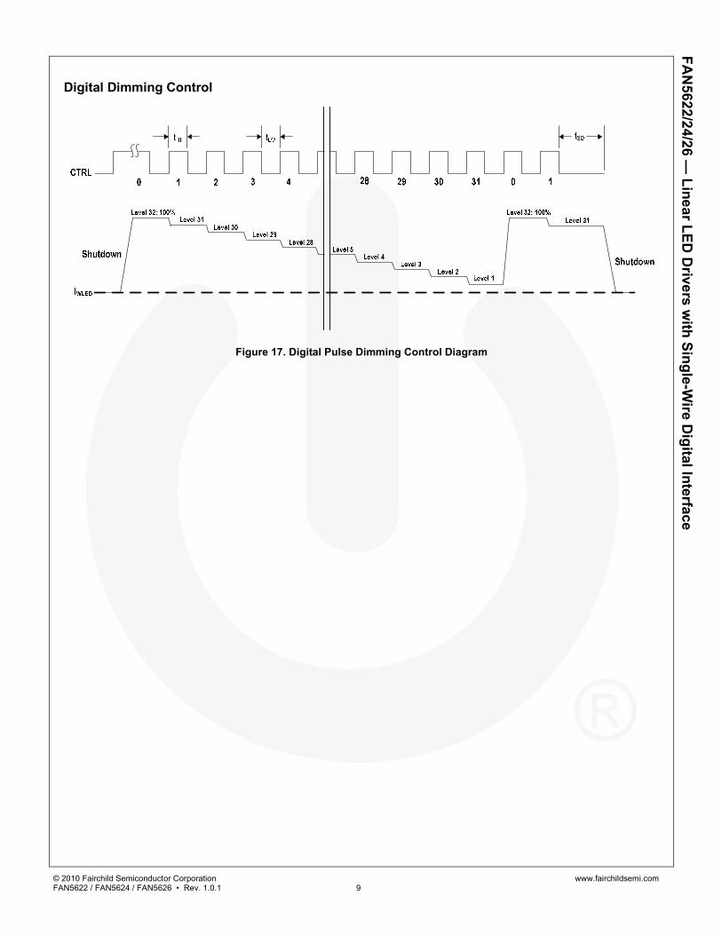
Digital Interface & Dimming Control The FAN5622, FAN5624, and FAN5626 implement a simple single-wire digital interface to program the LED brightness to one of thirty two (32) levels spaced in linear steps. To maintain the brightness of the LEDs at a specific dimming level, the digital pulse signal to the CTRL pin should be held HIGH for that last pulse. It is held HIGH for as long as desired to keep the LEDs illuminated at that specific brightness level.
Table 2 outlines the dimming levels while Figure 17 shows how to change the dimming levels.
Table 2. Brightness Control Levels (RSET = 19.10kΩ)
Dimming Level Current Level ILED (mA)
1 1.67% 0.25 2 3.33% 0.50 3 5.00% 0.75 4 6.67% 1.00 5 10.00% 1.50 6 13.33% 2.00 7 16.67% 2.50 8 20.00% 3.00 9 23.33% 3.50 10 26.67% 4.00 11 30.00% 4.50 12 33.33% 5.00 13 36.67% 5.50 14 40.00% 6.00 15 43.33% 6.50 16 46.67% 7.00 17 50.00% 7.50 18 53.33% 8.00 19 56.67% 8.50 20 60.00% 9.00 21 63.33% 9.50 22 66.67% 10.00 23 70.00% 10.50 24 73.33% 11.00 25 76.67% 11.50 26 80.00% 12.00 27 83.33% 12.50 28 86.67% 13.00 29 90.00% 13.50 30 93.33% 14.00 31 96.67% 14.50 32 100.00% 15.00
© 2010 Fairchild Semiconductor Corporation www.fairchildsemi.com FAN5622 / FAN5624 / FAN5626 • Rev. 1.0.1 9
FAN
5622/24/26 — Linear LED
Drivers w
ith Single-Wire D
igital Interface
Digital Dimming Control
Figure 17. Digital Pulse Dimming Control Diagram
© 2010 Fairchild Semiconductor Corporation www.fairchildsemi.com FAN5622 / FAN5624 / FAN5626 • Rev. 1.0.1 10
FAN
5622/24/26 — Linear LED
Drivers w
ith Single-Wire D
igital Interface
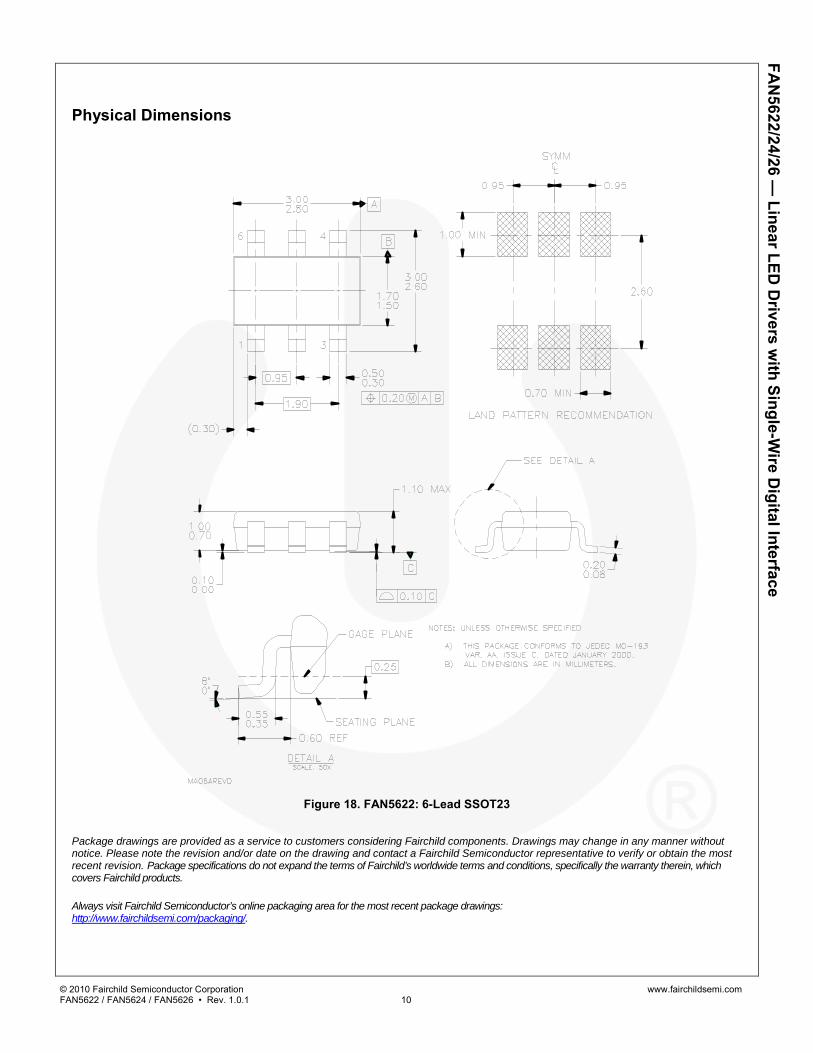
Physical Dimensions
Figure 18. FAN5622: 6-Lead SSOT23
Package drawings are provided as a service to customers considering Fairchild components. Drawings may change in any manner without notice. Please note the revision and/or date on the drawing and contact a Fairchild Semiconductor representative to verify or obtain the most recent revision. Package specifications do not expand the terms of Fairchild’s worldwide terms and conditions, specifically the warranty therein, which covers Fairchild products.
Always visit Fairchild Semiconductor’s online packaging area for the most recent package drawings: http://www.fairchildsemi.com/packaging/.
© 2010 Fairchild Semiconductor Corporation www.fairchildsemi.com FAN5622 / FAN5624 / FAN5626 • Rev. 1.0.1 11
FAN
5622/24/26 — Linear LED
Drivers w
ith Single-Wire D
igital Interface
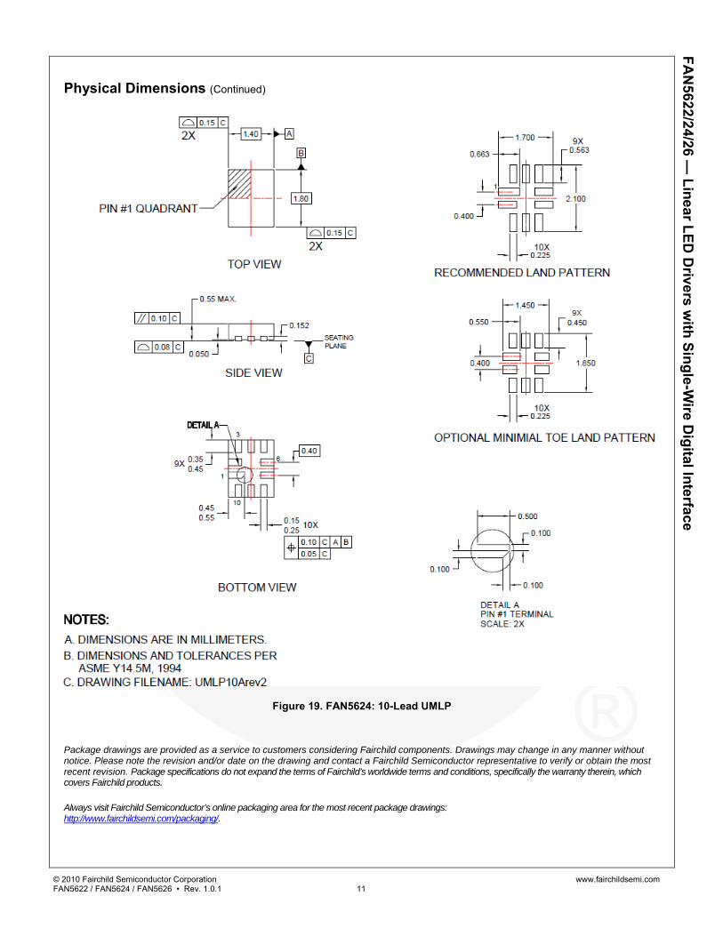
Physical Dimensions (Continued)
Figure 19. FAN5624: 10-Lead UMLP
Package drawings are provided as a service to customers considering Fairchild components. Drawings may change in any manner without notice. Please note the revision and/or date on the drawing and contact a Fairchild Semiconductor representative to verify or obtain the most recent revision. Package specifications do not expand the terms of Fairchild’s worldwide terms and conditions, specifically the warranty therein, which covers Fairchild products.
Always visit Fairchild Semiconductor’s online packaging area for the most recent package drawings: http://www.fairchildsemi.com/packaging/.
© 2010 Fairchild Semiconductor Corporation www.fairchildsemi.com FAN5622 / FAN5624 / FAN5626 • Rev. 1.0.1 12
FAN
5622/24/26 — Linear LED
Drivers w
ith Single-Wire D
igital Interface
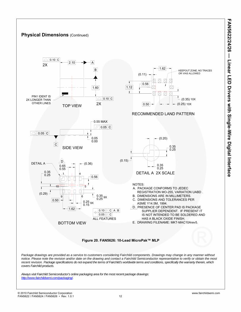
Physical Dimensions (Continued)
BOTTOM VIEW
TOP VIEW
RECOMMENDED LAND PATTERN
SIDE VIEW
2X
2X
NOTES:A. PACKAGE CONFORMS TO JEDEC REGISTRATION MO-255, VARIATION UABD .B. DIMENSIONS ARE IN MILLIMETERS.C. DIMENSIONS AND TOLERANCES PER ASME Y14.5M, 1994.D. PRESENCE OF CENTER PAD IS PACKAGE
SUPPLIER DEPENDENT. IF PRESENT ITIS NOT INTENDED TO BE SOLDERED ANDHAS A BLACK OXIDE FINISH.
E. DRAWING FILENAME: MKT-MAC10Arev5.
0.10 C
0.10 C
0.10 C A B0.05 C
PIN1 IDENT IS2X LONGER THAN
OTHER LINES
A
B
C
0.350.25
9X
9X
1 4
9 6
0.250.15
10 5
0.50
0.56
1.62
0.050.00
0.05 C
0.55 MAX
0.05 C
1.60
2.10
(0.35)(0.25)0.50
10X
10X
(0.11)
1.12
1.62KEEPOUT ZONE, NO TRACESOR VIAS ALLOWED
(0.20)
(0.15)0.350.25
0.350.25
DETAIL A
DETAIL A 2X SCALE0.350.25
0.650.55
D
ALL FEATURES
(0.36)
(0.29)
0.56
Figure 20. FAN5626: 10-Lead MicroPak™ MLP
Package drawings are provided as a service to customers considering Fairchild components. Drawings may change in any manner without notice. Please note the revision and/or date on the drawing and contact a Fairchild Semiconductor representative to verify or obtain the most recent revision. Package specifications do not expand the terms of Fairchild’s worldwide terms and conditions, specifically the warranty therein, which covers Fairchild products.
Always visit Fairchild Semiconductor’s online packaging area for the most recent package drawings: http://www.fairchildsemi.com/packaging/.
© 2010 Fairchild Semiconductor Corporation www.fairchildsemi.com FAN5622 / FAN5624 / FAN5626 • Rev. 1.0.1 13
FAN
5622/24/26 — Linear LED
Drivers w
ith Single-Wire D
igital Interface