Embed Size (px)
Citation preview

www.tecel.ru
FanControl‑GSM
Installation manual for VAG vehicles

FanControl‑GSM Installation manual for VAG vehicles
2
Module installation in VW Touareg (2011‑‑) vehicles
Group 3, subgroup 1Vehicle СAN bus:
• CАN‑L — orange with a brown stripe• CAN‑H — orange with a violet stripe.
Default control button:• Central lock locking button located on
driver’s door.
DoorsTrunkHoodFactory security system alertCentral lock state
Engine is runnningEngine temperatureOutside temperatureFuel levelControl via keyfobVentillation system support
Control of a factory heater Label located on the B‑pillar under the driver’s door indicates about presence of a factory heater.
Installation in a vehicle with activated timer The module is connected to САN bus at any convenient place, for instance, behind the climate
system control unit (Figure 1). Module CAN 1 paired wire is used for connection. For detailed description of connection refer to Diagram 1.
Figure 1. Menu with the timer
Installation in a vehicle without activated timer The module is connected to the vehicle CAN bus by cutting into it right after the climate system
control unit (Figure 2).
Figure 2

FanControl‑GSM Installation manual for VAG vehicles
3
When connecting the module to the CAN bus it is recommended to disassemble the relevant vehicle connector and then assemble it again using connector enclosures included in the kit (Figure 3).
Figure 3
Module CAN 1 and CAN 3 paired wires are designed for connection of the module to CAN bus: CAN 3 is connected to the bus from the climate system control unit side, and CAN 1 – from the vehicle’s side.
For detailed description of connection refer to Diagram 2.
Control of an aftermarket heater
The module allows switching on the vehicle climatic system in that mode which was used before ignition turn‑off and simultaneously starting an aftermarket heater.
Connection of the module The module is connected in the same way as described above: into the vehicle CAN bus right
after the climate system control unit. For detailed description of connection refer to Diagram 3.If installing heater on Volkswagen Touareg (2011‑‑) with gasoline engine (3.6 L) it is possible for following error to happen: Engine fan switches to maximum speed and “Check‑engine” error is detected. To remove the error service equipment is required.
FanControl allows to solve this issue. When connecting 2 conditions must be met:1. FanControl should control the heater via bus (blue/yellow wire). 2. Heater temperature should be limited. It can be done by using TECPROG or with built in
button (see main manual). Temperature should be picked individually for each vehicle.
Module can be set in mode where it’ll switch climate only if coolant has reached 40°. To do so “Alternative algorithm 1” should be activated. It can be done with TECPROG or manually:
1. Within 10 sec upon turning the ignition on press the programming button 14 times.2. The module shall inform about its status with one flash series.3. Press the programming button 1 time.4. The module shall inform about its status with series of two flashes.

FanControl‑GSM Installation manual for VAG vehicles
4
System installation in Porsche Cayenne (2011‑‑), Macan, Panamera (2009‑‑)
Group 3, subgroup 3Vehicle CAN bus:
• CАN‑L — orange with a brown stripe• CAN‑H — orange with a violet stripe.
Default control button:• ”Return“ button on the steering wheel
Doors Trunk Hood Factory security system alert Central lock state
Engine is runnning Engine temperature Outside temperature Fuel level Control via keyfob Ventillation system support
Control of a factory heater (only for Porsche Cayenne (2011--))
The module allows switching on the factory heater for engine and interior warm‑up.The module is connected to the vehicle CAN bus by cutting into it by cutting it right after the
climate system control unit (Figures 4, 5).
Figure 4 Figure 5
When connecting the module to the CAN bus it is recommended to disassemble the relevant vehicle connector and then assemble it again using connector enclosures included in the kit (Figure 6).
Module CAN 1 and CAN 3 paired wires are designed for connection of the module to CAN bus: CAN 3 is connected to the bus from the climate system control unit side, and CAN 1 – from the vehicle’s side.
For detailed description of connection refer to Diagram 9.
Figure 6
For correct operation of the pump, it is required to connect yellow/red wire (pin #11) with additional relay to the brown/blue wire (pin 12). Connection has to be performed near commutation unit under the gas pedal (Figure 7, 8).

FanControl‑GSM Installation manual for VAG vehicles
5
Figure 7 Figure 8
Control of a factory heater in Porsche Cayenne(2011--), Panamera (2009--) The module allows switching on the factory heater for engine and interior warm‑up.Module can be connected to CAN bus in any convenient place, for example behind the climate
control unit. CAN 1 has to be used for connection. To control factory heater it has to be launched once from the main menu.
If the heater operates as preheater:1. Connect red/black wire in the black connector of the heater (pin #3) to the ground through
70‑100 Ohm / 2.5 W resistor (figure 9)2. Enable factory heater in the vehicle by using diagnostic equipment3. Launch heater from the main menu (Outside temperature has to be lower than 40°С)Check connection scheme 10 for detailed description.
Figure 9
Control of an aftermarket heater The module allows switching on the vehicle climatic system in that mode which was used before
ignition turn‑off and simultaneously starting an aftermarket heater.
System installation The module is connected in the same way as described above: by cutting into the vehicle
CAN bus right after the climate system control unit. For detailed description of connection refer to Diagram 3

FanControl‑GSM Installation manual for VAG vehicles
6
System installation in Audi A6 (2011‑‑), A7
Group 3, subgroup 1Vehicle CAN bus:
• CАN‑L — orange with a brown stripe• CAN‑H — orange with a blue stripe
Standard control button:• Central lock locking button located on
driver’s door.
Doors Trunk Hood Factory security system alert Central lock state
Engine is runnning Engine temperature Outside temperature Fuel level Control via keyfob Ventillation system support
Control of an aftermarket heater The module allows switching on a vehicle’s climatic system and simultaneously starting an
aftermarket heater.
System installation The module is connected to the vehicle CAN bus by cutting into it right after the climate system
control unit (Figure 10).
Figure 10
When connecting the module to the CAN bus it is recommended to disassemble the relevant vehicle connector and then assemble it again using connector enclosures included in the kit (Figure 11).
Figure 11
Module CAN 1 and CAN 3 paired wires are designed for connection of the module to CAN bus: CAN 3 is connected to the bus from the climate system control unit side, and CAN 1 – from the vehicle’s side.
For detailed description of connection refer to Diagram 2.

FanControl‑GSM Installation manual for VAG vehicles
7
System installation in Audi A8 (2010‑‑)
Group 3, subgroup 1Vehicle CAN bus:
• CАN‑L — orange with a brown stripe• CAN‑H — orange with a violet stripe.
Standard control button:• Central lock locking button located on
driver’s door.
Doors Trunk Hood Factory security system Central lock state
Engine is running Engine temperature Outside temperature Fuel level Control via keyfob Ventillation system support
Control of an aftermarket heater The module allows switching on a vehicle’s climatic system and simultaneously starting an
aftermarket heater.
System installation The module is connected to the vehicle CAN bus by cutting into it right after the climate system
control unit (Figure 12).
Figure 12
When connecting the module to the CAN bus it is recommended to disassemble the relevant vehicle connector and then assemble it again using connector enclosures included in the kit (Figure 13).
Figure 13
Module CAN 1 and CAN 3 paired wires are designed for connection of the module to CAN bus: CAN 3 is connected to the bus from the climate system control unit side, and CAN 1 – from the vehicle’s side.
For detailed description of connection refer to Diagram 2.

FanControl‑GSM Installation manual for VAG vehicles
8
System installation in Audi A3 (2013‑‑), Audi TT (2015‑‑), VW Golf 7, Skoda Octavia 3
Group 3, subgroup 2Vehicle CAN bus:
• CАN‑L — orange with a brown stripe• CAN‑H — orange with a green stripe.
Standard control button:• Central lock locking button located on
driver’s door.
Doors Trunk Hood Factory security system alert Central lock state
Engine is runnning Engine temperature Outside temperature Fuel level Control via keyfob Ventillation system support
Control of an aftermarket heater The module allows switching on a vehicle’s climatic system and simultaneously starting an
aftermarket heater.
System installation The module is connected to the vehicle CAN bus by cutting into it right after the climate system
control unit (Figure 14). In Audi TT (2015‑‑) ‑ under the glovebox (figure 15).
Figure 14 Figure 15
When connecting the module to the CAN bus it is recommended to disassemble the relevant vehicle connector and then reassemble it using connector enclosures included in the kit (Figure 16).
Figure 16
Module CAN 1 and CAN 3 paired wires are designed for connection of the module to CAN bus: CAN 3 is connected to the bus from the climate system control unit side, and CAN 1 – from the vehicle’s side.
For detailed description of connection refer to Diagram 2.
Control of a factory heater in VW Golf 7 and Skoda Octavia The module allows switching on the factory heater for engine and interior warm‑up.
System installation The module is connected to the vehicle interior САN bus in any convenient place, for instance:
behind climate system control unit. Module CAN 1 paired wire is used for connection.

FanControl‑GSM Installation manual for VAG vehicles
9
System installation in Audi Q7 (2015‑‑)
Group 3, subgroup 5Vehicle CAN bus:
• CАN‑L — orange with a brown stripe• CAN‑H — black.
Standard control button:• Central lock locking button located on
driver’s door.
Doors Trunk Hood Factory security system alert Central lock state
Engine is runnning Engine temperature Outside temperature Fuel level Control via keyfob Ventillation system support
Control of an aftermarket heater The module allows switching on a vehicle’s climatic system and simultaneously starting an
aftermarket heater.
System installation System is connected by cutting into the CAN‑bus behind the left kick panel in the red
connector(figure 17).
Figure 17
Module CAN 1 and CAN 3 paired wires are designed for connection of the module to CAN bus: CAN 3 is connected to the bus from the climate system control unit side (upward harness), and CAN 1 – from the vehicle’s side.
For detailed description of connection refer to Diagram 2.
Control of a factory heater
Group 3, subgroup 4Vehicle CAN bus:
• CАN‑L — orange with a brown stripe• CAN‑H — orange with a brown stripe.
Standard control button:• Central lock locking button located on
driver’s door.
Doors Trunk Hood Factory security system alert Central lock state
Engine is runnning Engine temperature Outside temperature Fuel level Control via keyfob Ventillation system support
The module allows switching on a vehicle’s climatic system and simultaneously starting the heater.

FanControl‑GSM Installation manual for VAG vehicles
10
System installation System connects to the САN‑bus in the factory heater harness. connection can be made under
hood(figure 18).
Figure 18
Connecton is performed with CAN 1 wires. For detailed description of connection refer to Diagram 5.
System installation in Audi Q5, A5
Group 1, subgroup 1Vehicle CAN bus:
• CАN‑L — orange with a brown stripe• CAN‑H — orange with a brown stripe.
Standard control button:• Central lock locking button located on
driver’s door.
Doors Trunk Hood Factory security system alert Central lock state
Engine is runnning Engine temperature Outside temperature Fuel level Control via keyfob Ventillation system support
Control of an aftermarket heater The system allows switching on the vehicle climatic system in the mode that used before ignition
turn‑off and simultaneously start an aftermarket heater.
System installation
The module is connected to the vehicle CAN bus by cutting into it right after the climate system control unit (Figure 19) by paired wires CAN 1 and CAN 2.
Figure 19
When connecting the module to the CAN bus it is recommended to disassemble the relevant vehicle connector and then assemble it again using connector enclosures included in the kit (Figure 20).

FanControl‑GSM Installation manual for VAG vehicles
11
Figure 20
Module CAN 1 and CAN 2 paired wires are designed for connection of the module to CAN bus: CAN 2 is connected to the bus from the climate system control unit side, and CAN 1 – from the vehicle’s side.
For detailed description of connection refer to Diagram 4.
Control of a factory heater (Audi Q5) The module allows to switch on the factory heater for engine and interior warm‑up.Vehicle’s climatic system shall operate in that mode which was used before ignition turn‑off.
System installation The module is connected to the vehicle interior САN bus in any convenient place, for instance:
behind climate system control unit. Module CAN 1 paired wire is used for connection.For detailed description of connection refer to Diagram 1.
System installation in Audi Q3, Q7 (2011‑2014)
Audi Q7 Group 1, subgroup 2Audi Q3 Group 1, subgroup 3Vehicle CAN bus:
• CАN‑L — orange with a brown stripe• CAN‑H — orange with a green stripe.
Standard control button:• Central lock locking button located on
driver’s door.
Doors Trunk Hood Factory security system alert Central lock state
Engine is runnning Engine temperature *Outside temperature Fuel level *Control via keyfob Ventillation system support
* Only for Audi Q3.
FanControl‑GSM Installation manual for VAG vehicles
12
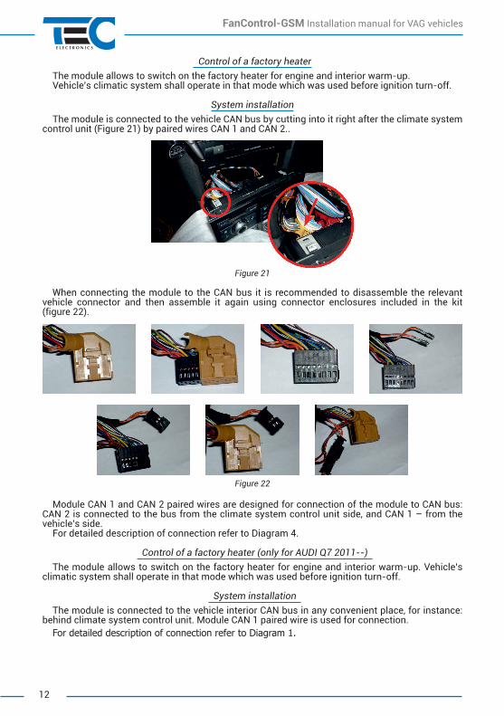
Control of a factory heaterThe module allows to switch on the factory heater for engine and interior warm‑up.Vehicle’s climatic system shall operate in that mode which was used before ignition turn‑off.
System installationThe module is connected to the vehicle CAN bus by cutting into it right after the climate system
control unit (Figure 21) by paired wires CAN 1 and CAN 2..
Figure 21
When connecting the module to the CAN bus it is recommended to disassemble the relevant vehicle connector and then assemble it again using connector enclosures included in the kit (figure 22).
Figure 22
Module CAN 1 and CAN 2 paired wires are designed for connection of the module to CAN bus: CAN 2 is connected to the bus from the climate system control unit side, and CAN 1 – from the vehicle’s side.
For detailed description of connection refer to Diagram 4.
Control of a factory heater (only for AUDI Q7 2011--) The module allows to switch on the factory heater for engine and interior warm‑up. Vehicle’s
climatic system shall operate in that mode which was used before ignition turn‑off.
System installation The module is connected to the vehicle interior САN bus in any convenient place, for instance:
behind climate system control unit. Module CAN 1 paired wire is used for connection.For detailed description of connection refer to Diagram 1.
FanControl‑GSM Installation manual for VAG vehicles
13
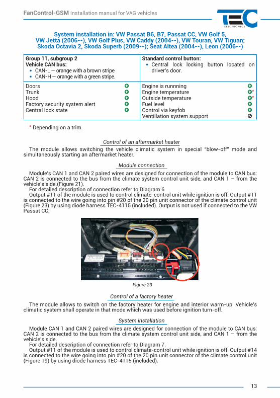
System installation in: VW Passat B6, B7, Passat CC, VW Golf 5, VW Jetta (2006‑‑), VW Golf Plus, VW Caddy (2004‑‑), VW Touran, VW Tiguan; Skoda Octavia 2, Skoda Superb (2009‑‑); Seat Altea (2004‑‑), Leon (2006‑‑)
Group 11, subgroup 2Vehicle CAN bus:
• CАN‑L — orange with a brown stripe• CAN‑H — orange with a green stripe.
Standard control button:• Central lock locking button located on
driver’s door.
Doors Trunk Hood Factory security system alert Central lock state
Engine is runnning Engine temperature *Outside temperature *Fuel level Control via keyfob Ventillation system support
* Depending on a trim.
Control of an aftermarket heaterThe module allows switching the vehicle climatic system in special “blow‑off” mode and
simultaneously starting an aftermarket heater.
Module connection Module’s CAN 1 and CAN 2 paired wires are designed for connection of the module to CAN bus:
CAN 2 is connected to the bus from the climate system control unit side, and CAN 1 – from the vehicle’s side.(Figure 21).
For detailed description of connection refer to Diagram 6Output #11 of the module is used to control climate‑control unit while ignition is off. Output #11
is connected to the wire going into pin #20 of the 20 pin unit connector of the climate control unit (Figure 23) by using diode harness TEC‑4115 (included). Output is not used if connected to the VW Passat CC.
Figure 23
Control of a factory heater The module allows to switch on the factory heater for engine and interior warm‑up. Vehicle’s
climatic system shall operate in that mode which was used before ignition turn‑off.
System installation Module CAN 1 and CAN 2 paired wires are designed for connection of the module to CAN bus:
CAN 2 is connected to the bus from the climate system control unit side, and CAN 1 – from the vehicle’s side.
For detailed description of connection refer to Diagram 7.Output #11 of the module is used to control climate‑control unit while ignition is off. Output #14
is connected to the wire going into pin #20 of the 20 pin unit connector of the climate control unit (Figure 19) by using diode harness TEC‑4115 (included).

FanControl‑GSM Installation manual for VAG vehicles
14
Output #10 of the module connects to the pin 2 of 8 pin connector with the included wire with pin that has to be installed into stock heater connector (Figure 24). Connection is performed on the right side behind front bumper (to ease access it is recommended to remove fog light).
On vehicles with 2010+ software update of stock Webasto heater eFC‑VAG module is required. Otherwise heater won’t be able to start. Pin 10 is not required to connect if eFC‑VAG module is installed.
Figure 24
System installation in: VW Multivan T5 (2003–2009), VW Multivan T5 (2010--) и VW Amarok
Group 11, subgroup 1Vehicle CAN bus:
• CАN‑L — orange with a brown stripe• CAN‑H — orange with a green stripe.
Standard control button:• Not avaliable.
Doors Trunk Hood Factory security system alert Central lock state
Engine is runnning Engine temperature *Outside temperature *Fuel level *Control via keyfob Ventillation system support
* Depending on a trim.
Control of a regular factory heater The module allows switching on a vehicle’s climatic system and simultaneously starting an
aftermarket heater. Some trim levels do not allow switching heater with stock button (close central lock).
System installation Module is connected to the interior CAN bus, for example: harness under driver’s seat, harness
behind climat controls, harness behind glove box or harness under right front seat.Only CAN 1 wires are used.Output #10 of the module connects to the pin 1 of 6 pin connector with the included wire with pin
that has to be installed into stock heater connector.On VW Multivan heater is located to the left of the underbody (under driver’s seat) and is covered.
Connectors located on top of the heater between the heater and the body, access to them can be restricted (Figures 25, 26).
To launch stock heater on VW Multivan that has factory launch timer connection to the heater isn’t required (pin 10 is not used). Launch is handled via CAN bus.
FanControl‑GSM Installation manual for VAG vehicles
15
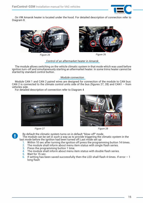
On VW Amarok heater is located under the hood. For detailed description of connection refer to Diagram 8.
Figure 25 Figure 26
Control of an aftermarket heater in Amarok
The module allows switching on the vehicle climatic system in that mode which was used before ignition turn‑off and simultaneously starting an aftermarket heater. In some trims heater cannot be started by standard control button.
Module connection Module CAN 1 and CAN 2 paired wires are designed for connection of the module to CAN bus:
CAN 2 is connected to the climate control units side of the bus (figures 27, 28) and CAN1 – from vehicles side.
For detailed description of connection refer to Diagram 4
Figure 27 Figure 28
By default the climatic system turns on in default “blow‑off” mode. The module can be set in such a way as to provide triggering the climatic system in the
last mode before the ignition had been turned off.Last mode set up:1. Within 10 sec after turning the ignition off press the programming button 14 times. 2. The module shall inform about menu item status with single flash series. 3. Press the programming button 1 time. 4. The module shall inform about menu item status with double flash series. 5. Wait for 15 sec. 6. If setting has been saved successfully then the LED shall flash 4 times. If error – 1
long flash

FanControl‑GSM Installation manual for VAG vehicles
16
Installation in VW Multivan T6 (2015‑‑)
Group 11, subgroup 3Vehicle CAN bus:
• CАN‑L — orange with a brown stripe• CAN‑H — orange with a green stripe.
Standard control button:• Not supported.
Doors Hood Trunk Factory security system alert Central lock state
Engine is runnning Engine temperature *Outside temperature *Fuel level *Control via keyfob Ventillation system support
* Depending on a trim.
Control of an aftermarket heater
Connection is made behind the KLA unit.System is connected by cutting into the CAN‑bus near KLA unit. System is connected by CAN 1
and CAN 2 wires: CAN 2 connects to the KLA side, and CAN 1 — from the vehicles side.When connecting the module to the CAN bus it is recommended to disassemble the relevant
vehicle connector and then assemble it again using connector enclosures included in the kit.For detailed description of connection refer to Diagram 4.
Climatic system turns on in the last used mode.
Control of a factory heater
Connection is made behind the KLA unit.System is connected by cutting into the KLA unit’s CAN‑bus. System is connected by CAN 1 and
CAN 2 wires: CAN 2 connects to the KLA and heater’s side, and CAN 1 — from the vehicles side. Heater can be connected in the red connector, under the driver’s seat (figure 29). Also pump has to be connected with yellow/red wire (pin №11), connection can be made into black 16‑pin connector to the yellow/green wire (pin №15) behind the KLA unit.
For detailed description of connection refer to Diagram 15.
Figure 29

FanControl‑GSM Installation manual for VAG vehicles
17
If vehicle is equipped with climate control with mechanical air temperature and blow direction controls, connect green/black wire (pin №23) of the module to the red/yellow wire at the climate control conntor through a relay (figure 30). It also requires electric pomp connection (yellow green wire), which is carried out with the help of a yellow/red wire of the module (pin №11) (figure 31).
Climate control system will turn on in the last mode.
Figure. 30 Figure 31
Control of a factory heater (if launch timer is present in the vehicle)
Group 11, subgroup 1Vehicle CAN bus:
• CАN‑L — orange with a brown stripe• CAN‑H — orange with a green stripe.
Standard control button:• Not supported.
System installation The module is connected to the vehicle interior САN bus in any convenient place, for instance:
behind climate system control unit. Module CAN 1 paired wire is used for connection.For detailed description of connection see Diagram 5.
System installation in: VW Touareg (2003–2010)
Group 11, subgroup 1Vehicle CAN bus:
• CАN‑L – orange with brown stripe• CAN‑H – orange with green stripe.
Standard control button:• Central lock locking button located on
driver’s door.
Doors Trunk Hood Factory security system alert Central lock state
Engine is runnning Engine temperature Outside temperature Fuel level Control via keyfob Ventillation system support
Control of a factory heater
A label located on the B‑pillar under the driver’s door indicates about presence of a factory heater.
The module allows to switch on the factory heater for engine and interior warm‑up.

FanControl‑GSM Installation manual for VAG vehicles
18
System installation Module is connected to interion CAN bus, for example behind climate control unit (Figure 32).
Only CAN 1 wires are used.
Figure 32Output #10 of the module connects to the pin 1 of 6 pin connector with the included wire with pin
that has to be installed into stock heater connector (Figure 33). Connection has to be performed behind the left front wheel.
Figure 33
For detailed description of connection refer to Diagram 8.
Control of an aftermarket heater
The module allows switching the vehicle’s climatic system in special “blow‑off” mode and simultaneously starting an aftermarket heater.
System installation
Module CAN 1 and CAN 2 paired wires are designed for connection of the module to CAN bus: CAN 2 is connected to the bus from the climate system control unit side (Figure 32), and CAN 1 – from the vehicle’s side.
For detailed description of connection refer to Diagram 2.
System installation in VW Crafter
Group 13, subgroup 1Vehicle CAN bus:
• CАN‑L – brown• CAN‑H – brown with red stripe.
Standard control button:• Steering wheel button ”Down“.
Doors Trunk Hood Factory security system alert Central lock state
Engine is runnning Engine temperature Outside temperature Fuel level Control via keyfob Ventillation system support

FanControl‑GSM Installation manual for VAG vehicles
19
Control of an aftermarket heater Connection is performed near KLA unit (figure 34).
• Brown‑red (CAN‑H)• Brown (CAN‑L)
Module has to be cutted into CAN bus going into KLA unit. CAN 1 and CAN 2 pairs are used to connect module to the CAN bus: CAN 2 has to be connected from the side of KLA unit and CAN 1 from the vehicle’s side. It is recommended to disassemble KLA connector, and then assemble it (use included pin covers). This way factory wiring will not be altered.
For detailed description of connection see Diagram 11.
Climate control system will turn on in the last mode.
Figure 34
Control of an original (factory) heater Connection is performed near KLA unit (figure 34).
• Brown‑red (CAN‑H)• Brown (CAN‑L)
Connect module to the CAN bus: CAN 2 has to be connected from the side of KLA unit and CAN 1 from the vehicle’s side. Connection can be made in the power distribution unit behind the glovebox (figure 35).
Connection is made by using twisted pair X30/24.6.For detailed description of connection see Diagram 12.
It is recommended to disassemble corresponding connector, and then assemble it (use included pin covers). This way factory wiring will not be altered.
Climate control system will turn on in the last mode.
If vehicle is equipped with mechanical temperature and airflow controls, connect green/black wire (pin 23) of the unit to the black/red wire of the climate system through a relay (pin 5) (Figure 36).
For detailed description of connection see Diagram 13.
Figure 35 Figure 36

FanControl‑GSM Installation manual for VAG vehicles
20
FanControl GSM 24
12
18
15
Red +12V
Black
Blue
Pink
/bla
ck
Climate control
(CAN-L brown, CAN-H brown/red)
"Return" button located on the steering wheel is used in Porsche Cayenne vehicles.CAN-H wire can be green in some revisions of the unit.
CAN 3 (CAN-L brown, CAN-H brown/green)
(status control)
(trigger control)
Control digital inputs for control of the module from external devices
FanControl GSM 24
12
18
15
Red+12V
Black
(CAN-L brown, CAN-H brown/red)
Blue
Pink
/bla
ckClimate control
(status control)
(trigger control)
Control digital inputs for control of the module from external devices
Diagram 2
Diagram 1

FanControl‑GSM Installation manual for VAG vehicles
21
FanControl GSM 24
12
18
15
23
1110
Gree
n/bl
ack
Yello
w/r
ed
Blue
/yel
low
Blue
Pink
/bla
ck
Aftermarket heater Climate
control
Red
Black
+12V
CAN 1 (CAN-L brown, CAN-H brown/red)
CAN 2 (CAN-L brown, CAN-H brown/yellow)
(status control)
(trigger control)
Control digital inputs for control of the module from external devices
Inputs for control of an aftermarket heater
FanControl GSM 24
12
23
1110 18
15
Gree
n/bl
ack
Yello
w/r
ed
Blue
/yel
low
Blue
Pink
/bla
ck
Aftermarket heater
Red
Black
+12V
CAN 1 (CAN-L brown, CAN-H brown/red)
CAN 3 (CAN-L brown, CAN-H brown/green)
Climate control
(status control)
(trigger control)
Control digital inputs for control of the module from external devices
Inputs for control of an aftermarket heater
"Return" button located on the steering wheel is used in Porsche Cayenne vehicles.
Diagram 4
Diagram 3

FanControl‑GSM Installation manual for VAG vehicles
22
FanControl GSM 24
12
11
15
1810
23
Inputs for control of an aftermarket heater
Blue
Pink
/bla
ck
Gre
en/b
lack
Blue
/yel
low
Yello
w/r
ed
Red
Black
Pink
or
Pink
/bla
ck
(status control)
(trigger control)
+12V
Climate control
Aftermarketheater
Pink
or
Pink
/bla
ck
20 pin connector
(CAN-L brown, CAN-H brown/red)CAN 1
(CAN-L brown, CAN-H brown/yellow)
CAN 2
FanControl GSM
18
15
24
12
Red
Black
(status control)
(trigger control)
Blue
Pink
/bla
ckClimate control
Control digital inputs for control of the module from external devices
+12V
CAN 1 (CAN-L brown, CAN-H brown/red)
Diagram 6
Diagram 5

FanControl‑GSM Installation manual for VAG vehicles
23
1
FanControl GSM 24
12
10
18
15
Factoryheater
Digital inputs to control the module from external devices
Climate control
+12V
6 pin connector
(status control)
(trigger control)
Red
Black
CAN 1 (CAN-L brown, CAN-H brown/red)
Blue
Pink
/bla
ck
If installing to VW Multivan T5 or VW Amarok module:• Does not allow turning the module on from stock button (central lock close)• On “Climatic” equipped vehicles output 14 is used to control additional fan control relay• On stock launch timer heater equipped vehicles input #5 is not required
FanControl GSM 24
12
11
18
15
10
Connection to the aftermarket heater is required only if eFC-VAG is not installed
Climate control
+12V
(status control)
(trigger control)
20 pin connector
Red
Black
CAN 1 (CAN-L brown, CAN-H brown/red)(CAN-L brown, CAN-H brown/yellow)
CAN 2
Blue
/yel
low
Blue
Pink
/bla
ckYe
llow
/red
Pink
or
Pink
/bla
ckPi
nk o
rPi
nk/b
lack
Factoryheater
Inputs for control of an aftermarket heater
8 pin connector
Diagram 8
Diagram 7

FanControl‑GSM Installation manual for VAG vehicles
24
Brow
n/bl
ue
Yello
w/r
ed
FanControl GSM 24
12
18
15
11
Red
Black
+12V
Climate control
Blue
Pink
/bla
ck
Digital inputs to control the module from external devices
(status control)
(trigger control)
CAN 1 (CAN-L brown, CAN-H brown/red)CAN 3 (CAN-L brown, CAN-H brown/green)
Diagram 9
Diagram 10
FanControl GSM 24
12
18
15
Blue
Pink
/bla
ck
CAN 1 (CAN-L brown, CAN-H brown/red)
Red
Black
(status control)
(trigger control)
Climate control
Control digital inputs for control of the module from external devices
+12V

FanControl‑GSM Installation manual for VAG vehicles
25
Diagram 11
Diagram 12
FanControl GSM 24
12
18
15
CAN 1 (CAN-L brown, CAN-H brown/red)
CAN 2 (CAN-L brown, CAN-H brown/yellow)
Red
Black
+12V
KLA unit
Factoryheater
Blue
Pink
/bla
ck
Status control
Trigger control
Digital input to control unit via additional devices
FanControl GSM 24
12
23
1110 18
15
Gre
en/b
lack
Yello
w/r
ed
Blue
/yel
low
Blue
Pi
nk/b
lack
Red
Black
+12V
CAN 1 (CAN-L brown, CAN-H brown/red)
CAN 2 (CAN-L brown, CAN-H brown/yellow)
Digital input to control unit via additional devices
Status control
Trigger controlOutputs to control additional heater
Aftermarketheater
KLA unit

FanControl‑GSM Installation manual for VAG vehicles
26
№5
FanControl GSM
18
15
23
24
12
Red
Black
+12V
Blue
Pink
/Bla
ck
CAN 1 (CAN-L brown, CAN-H brown/red)
CAN 2 (CAN-L brown, CAN-H brown/yellow)
+12V
Factory heater
Climate control
Addi
tiona
l rel
ay
Digital input to control unit via additional devices
Status control
Trigger control
Diagram 13
Diagram 14
FanControl
18
15
24
12
11
23
Red
Black
+12V
+12V
CAN 1 (CAN-L brown, CAN-H brown/red)CAN 2 (CAN-L brown, CAN-H brown/yellow)
Blue
Pi
nk/b
lack
Gre
en/b
lack
Yello
w/r
ed
Status control
Trigger control
Control digital inputs for control of the module from external devices
Climate control
Factoryheater
Addi
tiona
l rel
ay

FanControl‑GSM Installation manual for VAG vehicles
27TEC‑631910‑8
Diagram 15
FanControl 24
12
18
15
15
11
Red
Black
+12V
CAN 1 (CAN-L brown, CAN-H brown/red)
CAN 2 (CAN-L brown, CAN-H brown/yellow)
Blue
Pink
/bla
ck
Yellow/green
Yello
w/r
ed
Status control
Trigger control
Control digital inputs for control of the module from external devices
KLA unit
Factoryheater