Embed Size (px)
Citation preview
8/3/2019 Fans Blowers Nidhi 01
http://slidepdf.com/reader/full/fans-blowers-nidhi-01 1/66
Training Programme
on
CENTRE FOR RESEARCH AND INDUSTRIAL STAFF PERFORMANCE, CRISP Opposite Manas Bhawan, Shyamla Hills – Bhopal
Website : www.crispindia.com

8/3/2019 Fans Blowers Nidhi 01
http://slidepdf.com/reader/full/fans-blowers-nidhi-01 2/66
SECTION 1:
INTRODUCTION TO FAN SYSTEMS
For users unfamiliar with the basics of fans and fan systems, a brief discussion of the terms,
relationships, and important system design considerations is provided. This section describes
the key factors involved in fan selection and system design and provides an overview of
different types of fans and the applications for which they are generally used. Users already
familiar with fan system operation may want to skip this section. The key terms and
parameters used in selecting fans, designing systems, and controlling fluid flow are discussed.
1. Fans
2. Fan Performance Curves
3. Fan System Components
Section 2:
Performance Improvement Opportunity Roadmap
This section describes the key components of a fan system and the opportunities for
performance improvements. Also provided is a figurative system diagram identifying fan
system components and performance improvement opportunities. A set of fact sheets
describing these opportunities in greater detail follows the diagram. These fact sheets cover:
1. Assessing Fan System Needs
2. Fan Types
3. Basic Maintenance
4. Common Fan Systems Problems
5. Indications of Oversized Fans
6. System Leaks
7. Configurations to Improve Fan System Efficiency
8. Controlling Fans with Variable Loads
9. Fan Drive Options
10. Multiple-Fan Arrangements
11. Fan System Economics
8/3/2019 Fans Blowers Nidhi 01
http://slidepdf.com/reader/full/fans-blowers-nidhi-01 3/66
THE SYSTEMS APPROACH
The cost-effective operation and maintenance of a fan system requires attention not only to
the needs of the individual pieces of equipment, but also to the system as a whole. A“systems approach”analyzes both the supply and demand sides of the system and how they
interact, essentially shifting the focus from individual components to total system
performance. Often, operators are so focused on the immediate demands of the equipment
that they overlook the broader question of how system parameters are affecting the
equipment. The systems approach usually involves the following types of interrelated actions:
Establishing current conditions and operating parameters
Determining present and estimating future process production needs
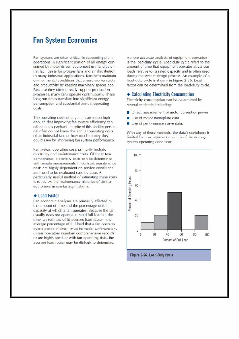
Gathering and analyzing operating data and developing load duty cycles
Assessing alternative system designs and improvements
Determining the most technically and economically sound options, taking into
consideration all of the subsystems
Implementing the best option
Assessing energy consumption with respect to performance
Continuing to monitor and optimize the system
Continuing to operate and maintain the system for peak performance.
8/3/2019 Fans Blowers Nidhi 01
http://slidepdf.com/reader/full/fans-blowers-nidhi-01 4/66
SECTION 1: INTRODUCTION TO FAN SYSTEMS
Fans are widely used in industrial and commercial applications. From shop ventilation to
material handling to boiler applications, fans are critical for process support and humanhealth. In the manufacturing sector, fans use about 78.7 billion kilowatt-hours2 of energy
each year. This consumption represents 15 percent of the electricity used by motors.3
Similarly, in the commercial sector, electricity needed to operate fan motors composes a
large portion of the energy costs for space conditioning. Performance may range from “free
air” to several pounds per square inch gage (psig)4, with airflow from a few cubic feet per
minute (cfm) to more than 1 million cfm. Pressures above 15 psig generally require air
compressors, which are addressed in a separate sourcebook titled Improving Compressed Air
System Performance, A Sourcebook for Industry. In manufacturing, fan reliability is critical to
plant operation. For example, where fans serve material handling applications, fan failure
will immediately create a process stoppage. In industrial ventilation applications, fan failure
will often force a process to be shut down (although there is often enough time to bring the
process to an orderly stoppage). Even in heating and cooling applications, fan operation is
essential to maintain a productive work environment. Fan failure leads to conditions in which
worker productivity and product quality declines. This is especially true for some production
applications in which air cleanliness is critical to minimizing production defects (for example,
plastics injection molding and electronic component manufacturing).
In each case, fan operation has a significant impact on plant production. The importance of
fan reliability often causes system designers to design fan systems conservatively. Concernedabout being responsible for under-performing systems, designers tend to compensate for
uncertainties in the design process by adding capacity to fans. Unfortunately, oversizing fan
systems creates problems that can increase system operating costs while decreasing fan
reliability.
Fans that are oversized for their service requirements do not operate at their best efficiency
points. In severe cases, these fans may operate in an unstable manner because of the point of
operation on the fan airflow-pressure curve. Oversized fans generate excess flow energy,
resulting in high airflow noise and increased stress on the fan and the system. Consequently,
oversized fans not only cost more to purchase and to operate, they create avoidable system
performance problems. The use of a “systems approach” in the fan selection process will
typically yield a quieter, more efficient, and more reliable system.
FANS

8/3/2019 Fans Blowers Nidhi 01
http://slidepdf.com/reader/full/fans-blowers-nidhi-01 5/66
There are two primary types of fans: centrifugal and axial. These types are characterized by
the path of the airflow through the fan. Centrifugal fans use a rotating impeller to increase
the velocity of an air stream. As the air moves from the impeller hub to the blade tips, it
gains kinetic energy. This kinetic energy is then converted to a static pressure increase as the
air slows before entering the discharge. Centrifugal fans are capable of generating relatively
high pressures. They are frequently used in “dirty” airstreams (high moisture and particulate
content),in material handling applications, and in systems at higher temperatures.
Axial fans, as the name implies, move an air stream along the axis of the fan. The air is
pressurized by the aerodynamic lift generated by the fan blades, much like a propeller and an
airplane wing.
Although they can sometimes be used interchangeably with centrifugal fans, axial fans arecommonly used in “clean air,” low-pressure, high-volume applications. Axial fans have less
rotating mass and are more compact than centrifugal fans of comparable capacity.
Additionally, axial fans tend to have higher rotational speeds and are somewhat noisier than
in-line centrifugal fans of the same capacity; however, this noise tends to be dominated by
high frequencies, which tend to be easier to attenuate.
Fan Selection
Fan selection is a complex process that starts with a basic knowledge of system operating
requirements and conditions such as airflow rates, temperatures, pressures, airstreamproperties, and system layout. The variability of these factors and other considerations, such
as cost, efficiency, operating life, maintenance, speed, material type, space constraints,
drive arrangements, temperature, and range of operating conditions, complicate fan
selection. However, knowledge of the important factors in the fan selection process can be
helpful for the purposes of reducing energy consumption during system retrofits or
expansions. Often, a fan type is chosen for non technical reasons, such as price, delivery,
availability, or designer or operator familiarity with a fan model. If noise levels, energy costs,
maintenance requirements, system reliability, or fan performance are worse than expected,
then the issue of whether the appropriate fan type was initially selected should be revisited.
Fans are usually selected from a range of models and sizes, rather than designed specificallyfor a particular application. Fan selection is based on calculating the airflow and pressure
requirements of a system, then finding a fan of the right design and materials to meet these
requirements. Unfortunately, there is a high level of uncertainty associated with predicting
system airflow and pressure requirements. This uncertainty, combined with fouling effects
and anticipated capacity expansion, encourages the tendency to increase the specified size of
a fan/motor assembly.

8/3/2019 Fans Blowers Nidhi 01
http://slidepdf.com/reader/full/fans-blowers-nidhi-01 6/66
Designers tend to protect against being responsible for inadequate system performance by
“overspecifying.” However, an oversized fan/motor assembly creates a different set of
operating problems, including inefficient fan operation, excess airflow noise, poor reliability,
and pipe/duct vibrations. By describing some of the problems and costs associated with poor
fan selection, this sourcebook is intended to help designers and operators improve fan system
performance through better fan selection and improved operating and maintenance practices.
Noise.
In industrial ventilation applications, noise can be a significant concern. High acoustic levels
promote worker fatigue. The noise generated by a fan depends on fan type, airflow rate, and
pressure. Inefficient fan operation is often indicated by a comparatively high noise level for a
particular fan type. If high fan noise levels are unavoidable, then ways to attenuate the
acoustic energy should be considered. Noise reduction can be accomplished by several
methods: insulating the duct; mounting the fan on a soft material, such as rubber or suitable
spring isolator as required to limit the amount of transmitted vibration energy; or installing
sound damping material or baffles to absorb noise energy.

8/3/2019 Fans Blowers Nidhi 01
http://slidepdf.com/reader/full/fans-blowers-nidhi-01 7/66
Rotational Speed.
Fan rotational speed is typically measured in revolutions per minute (rpm). Fan
rotational speed has a significant impact on fan performance, as shown by the
following fan laws:
Rotational speed must be considered concurrently with other issues, such as variation in the
fan load, airstream temperature, ambient noise, and mechanical strength of the fan.
Variations and uncertainties in system requirements are critical to fan type and fan rotational
speed selection. Fans that generate high airflow at relatively low speeds (for example,
forward-curved blade centrifugal fans) require a relatively accurate estimate of the system
airflow and pressure demand. If, for some reason, system requirements are uncertain, then
an improper guess at fan rotational speed can cause under-performance or excessive airflow
and pressure. Airstream temperature has an important impact on fan-speed limits because ofthe effect of heat on the mechanical strength of most materials. At high temperatures, all
materials exhibit lower yield strengths. Because the forces on shafts, blades, and bearings are
proportional to the square of the rotational speed, high-temperature applications are often
served by fans that operate at relatively low speeds.
8/3/2019 Fans Blowers Nidhi 01
http://slidepdf.com/reader/full/fans-blowers-nidhi-01 8/66
Airstream Characteristics.
Moisture and particulate content are important considerations in selecting fan type.
Contaminant build-up on fan blades can cause severe performance degradation and fan
imbalance. Build-up problems are promoted by a shallow blade angle with surfaces that allowcontaminants to collect. Fans with blade shapes that promote low-velocity air across the
blades, such as backward inclined fans, are susceptible to contaminant build-up. In contrast,
radial tip fans and radial blade fans operate so that airflow across the blade surfaces
minimizes contaminant build-up. These fans are used in “dirty” airstreams and in material
handling applications. Corrosive airstreams present a different set of problems. The fan
material, as well as the fan type, must be selected to withstand corrosive attack. Also,
leakage into ambient spaces may be a concern, requiring the fan to be equipped with a shaft
seal. Shaft seals prevent or limit leakage from around the region where the drive shaft
penetrates the fan housing. For example, in corrosive environments fans can be constructed
with expensive alloys that are strong and corrosion resistant, or they can be less expensivelyconstructed with fiber glass reinforced plastic or coated with a corrosionresistant material.
Because coatings are often less expensive than superalloy metals, fan types that work well
with coatings (for example, radial fan blades because of their simple shape) are widely used
in corrosive applications; however, wear will reduce the reliability of coatings. Alternately,
materials such as reinforced fiberglass plastics have been developed for fan applications and
function effectively in many corrosive environments. However, there may be size and speed
limitations for composite materials and plastic materials. Airstreams with high particulate
content levels can also be problematic for the fan drive train. In direct drive axial fans, the
motor is exposed to the airstream. Sealed motors can be used in these applications but tend
to be more expensive and, in the event of lost seal integrity, they are susceptible to
expensive damage. In axial fans, belt drives offer an advantage by removing the motor from
the airstream. In centrifugal fans, the particulate content is less of a factor because the
motor or sheave can be located outside of the fan enclosure and connected to the impeller
through a shaft seal. Gear drives are occasionally used in applications where speed reduction
is required but the use of belt drives is unfeasible because of access or maintenance
requirements. In flammable environments, fans are usually constructed of nonferrous alloys
to minimize the risk of sparks caused by metal-to-metal contact. In some applications, certain
components of the fan can be fabricated out of spark-resistant materials. Fans that operate
in flammable environments should be properly grounded, including rotating components, tominimize sparking because of static discharge.
Temperature Range.

8/3/2019 Fans Blowers Nidhi 01
http://slidepdf.com/reader/full/fans-blowers-nidhi-01 9/66
To a large degree, temperature range determines fan type and material selection. In high-
temperature environments, many materials lose mechanical strength. The stresses on rotating
components increase as the fan’s operating speed increases. Consequently, for high-
temperature applications, the fan type that requires the lowest operating speed for a
particular service is often recommended. Radial blade fans can be ruggedly constructed and
are frequently used in high-temperature environments. Component materials also
significantly influence a fan’s ability to serve in high-temperature applications, and different
alloys can be selected to provide the necessary mechanical properties at elevated
temperatures.
Variations in Operating Conditions.
Applications that have widely fluctuating operating requirements should not be served by fans
that have unstable operating regions near any of the expected operating conditions. Because
axial, backward inclined airfoil, and forward-curved fans tend to have unstable regions, these
fans are not recommended for this type of service unless there is a means of avoiding
operation in the unstable region, such as a recirculation line, a bleed feature, or some type of
anti-stall device.
Space Constraints.
Space and structural constraints can have a significant impact on fan selection. In addition to
dimensional constraints on the space available for the fan itself, issues such as maintenance
access, foundation and structural support requirements, and ductwork must be considered.
Maintenance access addresses the need to inspect, repair, or replace fan components.
Because downtime is often costly, quick access to a fan can provide future cost savings.
Foundation and structural requirements depend on the size and weight of a fan. Selecting a
compact fan can free up valuable floorspace. Fan weight, speed, and size usually determine
the foundation requirements, which, in turn, affect installation cost. If the available space
requires a fan to be located in a difficult configuration (for example, with an elbow just
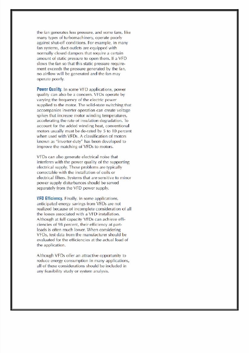
upstream or downstream of a fan), then some version of a flow straightened should beconsidered to improve the operating efficiency.
Because non-uniform airflow can increase the pressure drop across a duct fitting and will
degrade fan performance, straightening the airflow will lower operating costs. An important
tradeoff regarding space and fan systems is that the cost of floor space often motivates
designers and architects to configure a fan system within a tight space envelope. One way to

8/3/2019 Fans Blowers Nidhi 01
http://slidepdf.com/reader/full/fans-blowers-nidhi-01 10/66
accomplish this is to use small-radius elbows, small ducts, and very compact fan assemblies.
Although this design practice may free up floor space, the effect on fan system performance
can be severe in terms of maintenance costs. The use of multiple elbows close to a fan inlet
or outlet can create a costly system effect, and the added pressure drops caused by small
duct size or a cramped duct configuration can significantly increase fan operating costs.
System designers should include fan system operating costs as a consideration in configuring
fan assemblies and ductwork.
FAN PERFORMANCE CURVES
Fan performance is typically defined by a plot of developed pressure and power required over
a range of fan-generated airflow. Understanding this relationship is essential to designing,
sourcing, and operating a fan system and is the key to optimum fan selection.
Best Efficiency Point.
Fan efficiency is the ratio of the power imparted to the airstream to the power delivered by
the motor. The power of the airflow is the product of the pressure and the flow, corrected
for units consistency. The equation for total efficiency is an important aspect of a fan
performance curve is the best efficiency point (BEP), where a fan operates most cost-
effectively in terms of both energy efficiency and maintenance considerations.
Operating a fan near its BEP improves its performance and reduces wear, allowing longer
intervals between repairs. Moving a fan’s operating point away from its BEP increases bearing
loads and noise.
Another term for efficiency that is often used with fans is static efficiency, which uses static
pressure instead of total pressure in the above equation.When evaluating fan performance, it
is important to know which efficiency term is being used.

8/3/2019 Fans Blowers Nidhi 01
http://slidepdf.com/reader/full/fans-blowers-nidhi-01 11/66
Region of Instability
In general, fan curves arc downward from the zero flow condition—that is, as the
backpressure on the fan decreases, the airflow increases. Most fans have an operating region
in which their fan performance curve slopes in the same direction as the system resistancecurve.
A fan operating in this region can have unstable operation. (See Figure 1-1.) Instability results
from the fan’s interaction with the system; the fan attempts to generate more airflow, which
causes the system pressure to increase, reducing the generated airflow.As airflow decreases,
the system pressure also decreases, and the fan responds by generating more airflow. This
cyclic behavior results in a searching action that creates a sound similar to breathing. This
operating instability promotes poor fan efficiency and increases wear on the fan component.
Fan Start-Up.
Start-up refers to two different issues in the fan industry. Initial fan start-up is the
commissioning of the fan, the process of ensuring proper installation. This event is important
for several reasons. Poor fan installation can cause early failure, which can be costly both in
terms of the fan itself and in production losses. Like other rotating machinery, proper fan

8/3/2019 Fans Blowers Nidhi 01
http://slidepdf.com/reader/full/fans-blowers-nidhi-01 12/66
operation usually requires correct drive alignment, adequate foundation characteristics, and
true fit-up to connecting ductwork. Fan start-up is also the acceleration of a fan from rest to
normal operating speed. Many fans, particularly centrifugal types, have a large rotational
inertia (often referred to as WR2), meaning they require significant torque to reach operating
speed.
In addition to the WR2 load, the air mass moved by the fan also adds to the start-up torque
requirements on the fan motor. Although rotational inertia is not typically a problem in
heating, ventilation, and air conditioning (HVAC) applications, it may be a design
consideration in large industrial applications. Proper motor selection is essential in ensuring
that the fan can be brought to its operating speed and that, once there, the motor operates
efficiently. Because the start-up current for most motors is 2 to 5 times the running current,
the stress on the motor can be significantly reduced by starting a fan under its minimum
mechanical load and allowing the motor to achieve normal operating speed more quickly than
when under full load. In many applications, system dampers can be positioned to reduce theload on the fan motor during start-up. For example, the power required by a centrifugal fan
tends to increase with increasing flow (although in “non-overloading” fan types, the power
drops off after reaching a peak). In axial fans, the power tends to decrease with increasing
flow. Consequently, for most centrifugal fan types, large fan start-ups should be performed
with downstream dampers closed, while for most axial fan types, start-ups should be
performed with these dampers open.
However, there are exceptions to these guidelines, and the actual power curve for the fan
should be evaluated to determine how to soften the impact of a large fan start-up. The power
surges that accompany the starting of large motors can create problems. Among the effects ofa large start-up current are power quality problems and increased wear on the electrical
system. In response to increasing demand for equipment that minimizes the problems
associated with large motor starts, electrical equipment manufacturers are offering many
different technologies, including special devices known as soft starters, to allow gradual
motor speed acceleration. A key advantage of variable frequency drives (VFDs) is that they
are often equipped with soft starting features that decrease motor starting current to about
1.5 to 2 times the operating current. Although VFDs are primarily used to reduce operating
costs, they can significantly reduce the impact of fan starts on an electrical system.
In axial fan applications, controllable pitch fans offer a similar advantage with respect to
reducing start-up current. Shifting the blades to a low angle of attack reduces the required
start-up torque of the fan, which allows the motor to reach operating speed more quickly.
System Effect.
8/3/2019 Fans Blowers Nidhi 01
http://slidepdf.com/reader/full/fans-blowers-nidhi-01 13/66
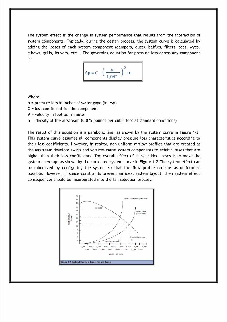
The system effect is the change in system performance that results from the interaction of
system components. Typically, during the design process, the system curve is calculated by
adding the losses of each system component (dampers, ducts, baffles, filters, tees, wyes,
elbows, grills, louvers, etc.). The governing equation for pressure loss across any component
is:
Where:
p = pressure loss in inches of water gage (in. wg)
C = loss coefficient for the component
V = velocity in feet per minute
ρ = density of the airstream (0.075 pounds per cubic foot at standard conditions)
The result of this equation is a parabolic line, as shown by the system curve in Figure 1-2.
This system curve assumes all components display pressure loss characteristics according to
their loss coefficients. However, in reality, non-uniform airflow profiles that are created as
the airstream develops swirls and vortices cause system components to exhibit losses that are
higher than their loss coefficients. The overall effect of these added losses is to move the
system curve up, as shown by the corrected system curve in Figure 1-2.The system effect can
be minimized by configuring the system so that the flow profile remains as uniform aspossible. However, if space constraints prevent an ideal system layout, then system effect
consequences should be incorporated into the fan selection process.

8/3/2019 Fans Blowers Nidhi 01
http://slidepdf.com/reader/full/fans-blowers-nidhi-01 14/66
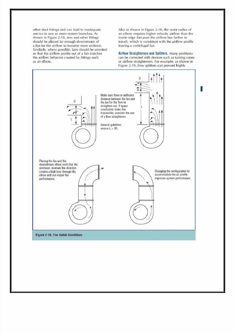
The system effect can be particularly problematic when the airflow into or out of a fan is
disrupted into a highly non-uniform pattern. Poor configuration of ductwork leading to or
from a fan can severely interfere with a fan’s ability to efficiently impart energy to an
airstream. For example, placing an elbow close to the fan outlet can create a system effect
that decreases the delivered flow by up to 30 percent. This can require an increase in fan
speed, which in turn results in an increase in power and a decrease in system efficiency.
Although underestimating the system effect causes insufficient air delivery, many designers
overcompensate for it and other uncertainties by selecting oversized fans. This practice
creates problems such as high energy costs, high maintenance, and reduced system
reliability. A more reasonable approach is to combine proper system layout practices with an
accurate estimate of the system effect to determine an appropriate fan size.
FAN SYSTEM COMPONENTS
A typical fan system consists of a fan, an electric motor, a drive system, ducts or piping, flow
control devices, and air conditioning equipment (filters, cooling coils, heat exchangers, etc.).
An example system is illustrated in a diagram on page 10.To effectively improve the
performance of fan systems, designers and operators must understand how other system
components function as well.
The “systems approach” requires knowing the interaction between fans, the equipment that
supports fan operation, and the components that are served by fans.

8/3/2019 Fans Blowers Nidhi 01
http://slidepdf.com/reader/full/fans-blowers-nidhi-01 15/66
Prime Movers.
Most industrial fans are driven by alternating current (AC) electric motors. Most are
induction motors supplied with three-phase,240- or 480-volt power. Because power supplies
are typically rated at slightly higher voltages than motors because of anticipated voltagedrops in the distribution system, motors are typically rated at 230 or 460 volts. In recent
years, because of efforts by the National Electrical Manufacturers Association (NEMA) and
motor manufacturers, the efficiency of general-purpose motors has significantly improved.
These improvements are also attributable to the Energy Policy Act (EPAct), which for most
motors went into effect in October 1997.To improve motor efficiency, motor manufacturers
have modified motor designs and incorporated better materials, resulting in slight changes in
motor operating characteristics. Although initial costs of the motors have increased 10 to 20
percent, for high run-time applications, improvements in motor efficiency create very
attractive paybacks through lower operating costs.
A characteristic of induction motors is that their torque is directly related to slip, or the
difference between the speed of the magnetic field and the speed of the motor shaft.
Consequently, in many fans, actual operating speeds are usually around 2 percent less than
their nominal speeds. For example, a theoretical four-pole induction motor with no slip would
rotate at 1,800 rpm with a 60-hertz power supply; however, rated operating speeds for this
motor are usually around 1,750 rpm, indicating that slip rates are a little over 2.7 percent at
rated load. Fans that are driven by older motors are probably operating at much lower
efficiencies and at higher levels of slip than what is available from new motors. Upgrading to
a new motor can reduce operating costs, because of improved motor efficiency, while
offering slightly improved fan performance. EPAct efficiency motors operate with less slip,
which means fans rotate at slightly higher speeds. For applications that can effectively use
this additional output, this high efficiency can be attractive.
However, if the additional output is not useful, the added power consumption increasesoperating costs.
Another component of the prime mover is the motor controller. The controller is the switch
mechanism that receives a signal from a low power circuit, such as an on/off switch, and
energizes or de-energizes the motor by connecting or disconnecting the motor windings to the
power line voltage.
Soft starters are electrical devices that are often installed with a motor controller to reduce
the electrical stresses associated with the start-up of large motors. In conventional systems,
the high in-rush and starting currents associated with most AC motors creates power quality
problems, such as voltage sag. Soft starters gradually ramp up the voltage applied to the

8/3/2019 Fans Blowers Nidhi 01
http://slidepdf.com/reader/full/fans-blowers-nidhi-01 16/66
motor, reducing the magnitude of the start-up current. As industrial facilities increase the
use of computer-based equipment and control systems, soft starters are becoming important
parts of many motor control systems. In fact, a major advantage associated with most VFDs is
that they often have built-in, soft-start capabilities.
Another common characteristic of motors used in fan applications is multiple speed
capability. Because ventilation and air-moving requirements often vary significantly, the
ability to adjust fan speed is useful. Motors can be built to operate at different speeds in two
principal ways: as a single set of windings equipped with a switch that energizes or de-
energizes an additional set of poles, or with the use of multiple windings, each of which
energizes a different number of poles. The first type of motor is known as a consequent pole
motor and usually allows two operating speeds, one twice that of the other. The second type
of motor can have two, three, or four speeds, depending on application. In general, multiple
speed motors are more costly and less efficient than single-speed motors. However, the flow
control benefit of different motor speeds makes them attractive for many fan applications.
Drive System.
The drive system often offers substantial opportunities to improve energy efficiency and to
lower overall system operating costs. There are two principal types of drive systems:
direct drive and belt drive. Gear drives are also used but are less common. In direct drive
systems, the fan is attached to the motor shaft. This is a simple, efficient system but has lessflexibility with respect to speed adjustment. Because most fans are operated with induction
motors, the operating rotational speeds of direct drive fans are limited to within a few
percent of the synchronous motor speeds (most commonly 1,200, 1,800, and 3,600 rpm). The
sensitivity of fan output to its operating rotational speed means that errors in estimating the
performance requirements can make a direct-drive system operate inefficiently (unlike belt
drives, which allow fan rotational speed adjustments by altering pulley diameters).
One way to add rotational speed flexibility to a direct-drive system is to use an adjustable
speed drive (ASD). ASDs allow a range of shaft speeds and are quite practical for systems that
have varying demand. Although ASDs are generally not a practical option for fans that areonly required to operate at one speed, ASDs can provide a highly efficient system for fans
that operate over a range of conditions. In axial fans, direct drives have some important
advantages. Applications with low temperatures and clean system air are well-suited for
direct drives because the motor mounts directly behind the fan and can be cooled by the
airstream. This space-saving configuration allows the motor to operate at higher-than-rated
loads because of added cooling. However, accessibility to the motor is somewhat restricted.
8/3/2019 Fans Blowers Nidhi 01
http://slidepdf.com/reader/full/fans-blowers-nidhi-01 17/66
Belt drives offer a key advantage to fan systems by providing flexibility in fan speed selection.
If the initial estimates are incorrect or if the system requirements change, belt drives allow
flexibility in changing fan speed.
In axial fans, belt drives keep the motor out of the airstream, which can be an advantage in
high temperature applications, or in dirty or corrosive environments. There are several
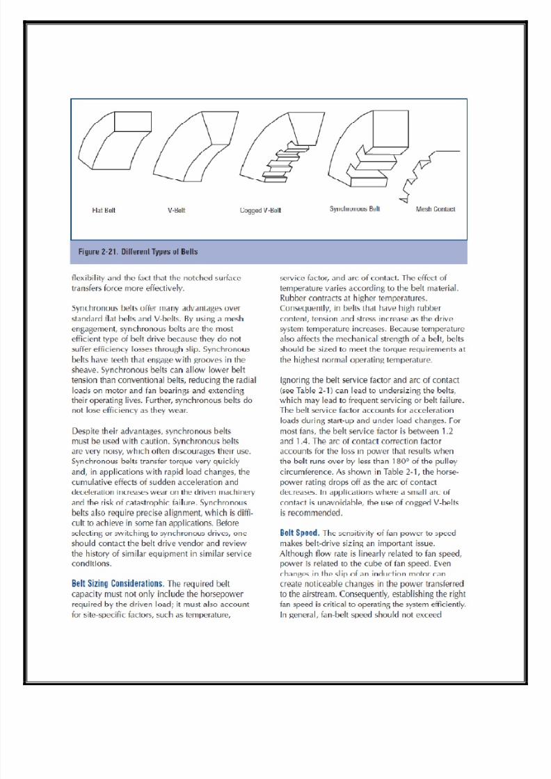
different types of belt drives, including standard belts, V-belts, cogged V-belts, and
synchronous belts. There are different cost and operating advantages to each type. In
general, synchronous belts are the most efficient, while V-belts are the most commonly used.
Synchronous belts are highly efficient because they use a meshtype contact that limits
slippage and can lower operating costs. However, switching to synchronous belts must be
done with caution. Synchronous belts usually generate much more noise than other belts.
They also transfer shock loads through the drivetrain without allowing slip. These sudden load
changes can be problematic for both motors and fans. Another problem with synchronous
belts is the limited availability of pulley sizes. Because the pulleys have a mesh pattern,machining them alters the pitch diameter, which interferes with engagement. Consequently,
pulleys are available in discrete sizes, which precludes an important advantage of belt drives:
the ability to alter operating rotational speeds by adjusting sheave diameters.
Because of these factors, synchronous belts are not as widely used as V-belts in fan
applications. In contrast, V-belts are widely used because of their efficiency, flexibility, and
robust operation. V-belts have a long history in industrial applications, which means there is a
lot of industry knowledge about them. An important advantage to V-belts is their protection
of the drivetrain during sudden load changes. Service conditions that experience sudden
drivetrain accelerations cause accelerated wear or sudden failure. While synchronous beltstend to transfer these shock loads directly to the shafts and motors, V-belts can slip,
affording some protection. Although they are less efficient than synchronous belts, V-belts
offer many advantages such as low cost, reliable operation, and operating flexibility. In
applications that use standard belts, upgrades to V-belts should be considered.
Although they are not commonly used, gear systems offer some advantages to belt systems.
Gear systems tend to be much more expensive than belt drive alternatives; however, gears
tend to require less frequent inspection and maintenance than belts and are preferable in
applications with severely limited access. Gears also offer several motor/fan configurations,
including in-line drives, parallel offset drives, and 90-degree drives, each of which may
provide an attractive advantage in some applications. Gear-system efficiency depends largely
on speed ratio. In general, gear efficiencies range from 70 to 98 percent. In large horsepower
(hp) applications (greater than 100 hp), gear systems tend to be designed for greater
efficiency because of the costs, heat, and noise problems that result from efficiency losses.
Because gears require lubrication, gearbox lubricant must be periodically inspected and

8/3/2019 Fans Blowers Nidhi 01
http://slidepdf.com/reader/full/fans-blowers-nidhi-01 18/66
changed. Also, because gears—like synchronous belts—do not allow slip, shock loads are
transferred directly across the drivetrain.
Ductwork or Piping.
For most fan systems, air is directed through ducts or pipes. In general, ducts are made of
sheet metal and used in low-pressure systems, while pipes are sturdier and used in higher-
pressure applications. Because ducts are used for most air-moving applications, “duct” will be
the common reference for this sourcebook; however, most of the same principles can be
applied to pipes.
In ventilation applications in which a fan pulls directly from a ventilated space on one side
and discharges directly to an external space (like a wall-mounted propeller fan), duct losses
are not a significant factor. However, in most applications, ducts are used on one or both
sides of a fan and have a critical impact on fan performance. Friction between the airstream
and the duct surface is usually a significant portion of the overall load on a fan. As a rule,
larger ducts create lower airflow resistance than smaller ducts. Although larger ducts have
higher initial costs in terms of material and installation, the reduced cost of energy because
of lower friction offsets some of these costs and should be included during the initial design
process and during system modification efforts.
Other considerations with ducts are their shape and leakage class. Round ducts have less
surface area per unit cross sectional area than rectangular ducts and, as a result, have lessleakage. In hot or cool airstreams, this surface area also influences the amount of heat
transferred to the environment. Duct leakage class, typically identified by the factor CL
(which has units of cfm/linear foot) is an indicator of duct integrity. Variables that determine
CL include the type of joints used in construction, the number of joints per unit length of
duct, and the shape of the duct. Depending on the length of the duct system, leakage can
account for a significant portion of a fan’s capacity. This is especially applicable to systems
with rectangular ducts that have unsealed joints. In many cases, the system designer can
improve the performance of the ventilation system by specifying ducts that have low CL’S
Airflow Control Devices.
Flow control devices include inlet dampers on the box, inlet vanes at the inlet to the fan,
and outlet dampers at the outlet of the fan. Inlet box dampers are usually parallel blade
dampers. Inlet vanes adjust fan output in two principal ways: by creating a swirl in the

8/3/2019 Fans Blowers Nidhi 01
http://slidepdf.com/reader/full/fans-blowers-nidhi-01 19/66
airflow that affects the way in which the air hits the fan blades, or by throttling the air
altogether, which restricts the amount of air entering the fan. The inlet vanes and dampers
must be designed for proper fan rotation and are to be installed in such a way that these inlet
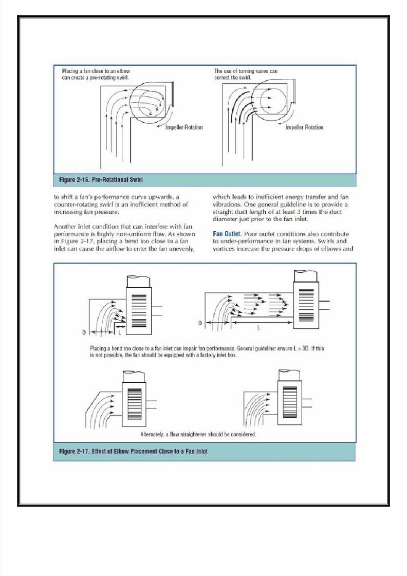
vanes and dampers open in the same direction as the fan rotation. The prerotation or swirl of
the air helps reduce the brake horsepower of the fan. If the inlet dampers on the inlet box
are located too far away from the inlet of the fan, the effect of pre-rotation may be lost or
reduced, and horsepower savings may be negligible.
The outlet damper, when used for controlling airflow, is usually of opposed-blade design for
better flow distribution on the discharge side of the fan. If the outlet damper is going to be
used for open/close service or for isolating the fan, a parallelblade discharge damper may be
used. Typically, fans with inlet vanes provide better power savings while operating the fan at
part load conditions, as opposed to fans with inlet box dampers operating in a similar
situation. Inlet vanes provide better controllability with optimum power savings compared to
other dampers. Outlet dampers adjust resistance to airflow and move the operating pointalong the fan’s performance curve. Because they do not change air entry conditions, outlet
dampers do not offer energy savings other than shifting the operating point along the fan
horsepower curve. Dampers can be used to throttle the air entering or leaving a fan and to
control airflow in branches of a system or at points of delivery.
Dampers control airflow by changing the amount of restriction in an airstream. Increasing the
restriction creates a larger pressure drop across the damper and dissipates some flow energy,
while decreasing the restriction reduces the pressure differential and allows more airflow.
From a system perspective, proper use of dampers can improve energy efficiency over
traditional system designs, especially in HVAC systems. In variable-air volume (VAV) systems,dampers are effective at rerouting airflow and at controlling the amount of air delivered to a
particular workspace. Because VAV systems are much more energy efficient than their
precursors (constant-volume or dual-supply systems), dampers can be used to lower system
operating costs.
However, in many applications, dampers can decrease fan efficiency. Dampers decrease total
fan output by increasing backpressure, which forces the operating point of a fan to shift to
the left along its performance curve. Often, as the fan operating point moves to the left
along its curve, it operates less efficiently and, in some cases, may perform in an unstablemanner. Unstable fan operation is the result of an aerodynamic phenomenon in which there is
insufficient air moving across the fan blades. The airflow rate surges back and forth resulting
in inefficient performance, annoying noise characteristics, and accelerated wear on the fan
drive system. Another airflow control method that is available for axial fan applications is the
use of variable pitch blades. Variable pitch fans control fan output by adjusting the fan blade
angle of attack with respect to the incoming airstream. This allows the fan to increase or
8/3/2019 Fans Blowers Nidhi 01
http://slidepdf.com/reader/full/fans-blowers-nidhi-01 20/66
decrease its load in response to system demand. In effect, this method is similar to that
provided by inlet vanes, which adjust the angle of attack of the entering airstream by
creating a swirl in the airflow pattern. Variable pitch fans provide a highly efficient means of
matching fan output to system demand.
Another method of airflow control is fan speed adjustment. Recalling the fan laws, speed has
a linear relationship with airflow, a second-order relationship with pressure, and a third-order
relationship with power. By slowing or speeding up a fan, its output can be adjusted to match
system demand. In general, fan speed adjustment is the most efficient method of airflow
control. There are two primary speed control options: multiple-speed motors and ASDs.
Multiple-speed motors have discrete speeds, such as “high,” “medium,” and “low.” Although
these motors tend to be somewhat less efficient than single speed motors, they offer
simplicity, operating flexibility, a relatively compact space envelope, and significant energy
savings for fan systems with highly variable loads. ASDs include several different types of
mechanical and electrical equipment. The most common type of ASD is a VFD.
VFDs control the frequency of the power supplied to a motor to establish its operating speed.
Unlike multiple speed motors that operate at discrete speeds, VFDs allow motors to operate
over a continuous range of speed. This flexibility provides accurate matching between fan
output and the flow and pressure requirements of the system.
Air Conditioning and Process Equipment (Filters, Heat Exchangers, etc.).
Other equipment commonly found in air-moving systems includes devices used to condition
the airstream to obtain certain properties. Heat exchangers are used to heat or cool an
airstream to achieve a particular temperature or to remove moisture. Filters are used to
remove unwanted particles or gases. Conditioning equipment influences fan performance by
providing flow resistance and, in some cases, by changing air density. Filters, including
cyclone types or mesh types, inherently create pressure drops, which are often significant
components of the overall system pressure drop. Mesh-type filters create increasingly large
pressure drops as they accumulate particles.In many systems, poor performance is a direct
result of inadequate attention to filter cleanliness. Cyclone filters remove particulates by
rapidly altering the direction of the airflow so that heavy particulates, unable to changedirection quickly,get trapped. Although cyclone filters are less effective than mesh filters,
they tend to require less maintenance and have more stable pressure-drop characteristics.
The effects of heating and cooling coils on fan system performance depend largely on where
in the system the heat exchangers are located, the extent of the temperature change, and

8/3/2019 Fans Blowers Nidhi 01
http://slidepdf.com/reader/full/fans-blowers-nidhi-01 21/66
how the heat exchangers are constructed. Where there are large changes in airstream
temperature, fan performance can change as the air density changes. Heat exchangers that
have closely spaced fins can accumulate particulates and moisture that not only impact heat
transfer properties, but also increase pressure losses.
SECTION 2:
PERFORMANCE IMPROVEMENT OPPORTUNITY ROADMAP
The cost-effective operation and maintenance of a fan system requires attention to the needs
of both individual equipment and the entire system. Often, operators are so focused on the
immediate demands of the equipment that they overlook the broader perspective of how the
system parameters are affecting this equipment. A “systems approach” analyzes a system and
how its components interact, essentially shifting the focus from individual components tototal system performance. The systems approach usually involves the following types of
interrelated actions:
Establishing current conditions and operating parameters
Determining the present and estimating future process production needs
Gathering and analyzing operating data and developing load duty cycles
Assessing alternative system designs and improvements
Determining the most technically and economically sound options, taking into
consideration all of the subsystems
Implementing the best option
Assessing energy consumption with respect to performance
Continuing to monitor and optimize the system
Continuing to operate and maintain the system for peak performance.
The remainder of this section is a collection of 11 fact sheets that address both component
and system issues. Each fact sheet details a specific opportunity for improving fan system
performance.

8/3/2019 Fans Blowers Nidhi 01
http://slidepdf.com/reader/full/fans-blowers-nidhi-01 22/66
FACT SHEETS
1—Assessing Fan System Needs
2—Fan Types
3—Basic Maintenance4—Common Fan System Problems
5—Indications of Oversized Fans
6—System Leaks
7—Configurations to Improve Fan System Efficiency
8—Controlling Fans with Variable Loads
9—Fan Drive Options
10–Multiple-Fan Arrangements
11–Fan System Economics
ASSESSING FAN SYSTEM NEEDS
There are three principal opportunities in the life cycle of a system that can be used to
improve fan system performance:
During initial system design and fan selection
During troubleshooting to solve a system problem
During a system capacity modification.
Initial Fan Selection
Fan selection starts with a basic knowledge of system operating conditions: air properties
(moisture content, temperature, density, contaminant level, etc.),airflow rate, pressure, and
system layout. These conditions determine which type of fan—centrifugal or axial—is required
to meet service needs.Axial fans move air along the direction of the fan’s rotating axis, much
like a propeller. Axial fans tend to be light and compact. Centrifugal fans accelerate air
radially, changing the direction of the airflow.They are sturdy, quiet, reliable, and capable of
operating over a wide range of conditions. Many factors are used to determine whether axialor centrifugal fans are more appropriate for certain applications. After deciding which fan
type is appropriate, the right size must be determined. Fans are usually selected on a “best-
fit” basis rather than designed specifically for a particular application.
A fan is chosen from a wide range of models based on its ability to meet the anticipated
demands of a system. Fans have two mutually dependent outputs: airflow and pressure. The
8/3/2019 Fans Blowers Nidhi 01
http://slidepdf.com/reader/full/fans-blowers-nidhi-01 23/66
variability of these outputs and other factors, such as efficiency, operating life, and
maintenance, complicate the fan selection process.
Tendency to Oversize.
A conservative design tendency is to source a fan/motor assembly that will be large enough to
accommodate uncertainties in system design, fouling effects, or future capacity increases.
Designers also tend to oversize fans to protect against being responsible for inadequate
system performance.
However, purchasing an oversized fan/motor assembly creates operating problems such as
excess airflow noise and inefficient fan operation. The incremental energy costs of operating
oversized fans can be significant.
Troubleshooting a System Problem
Some fan system problems, such as abnormally high operating and maintenance costs and
ineffective airflow control, are sufficiently troublesome to justify a system assessment. If the
system problems are significant, then a change to the fan, its drive system,or the airflow
control devices may be justifiable.
High Operating and Maintenance Costs.
Unusually high operating costs are often caused by inefficient fan operation that, in turn, can
be the result of improper fan selection, poor system design, or wasteful airflow control
practices. Improper fan selection often means the fan is oversized for the application,
resulting in high energy costs, high airflow noise, and high maintenance requirements. Poor
system design can lead to high operating and maintenance costs by promoting poor airflow
conditions. For example, duct configurations that create large system effect factors can
cause significant efficiency and airflow losses.
An effective way of minimizing maintenance and operating costs is to keep a fan operating
within a reasonable range of its best efficiency point (BEP).However, this practice is often
difficult in systems that have changing demands.
Poor Airflow Control.

8/3/2019 Fans Blowers Nidhi 01
http://slidepdf.com/reader/full/fans-blowers-nidhi-01 24/66
Poor airflow control refers to a wide range of causes and problems, including inadequate
delivery to a system branch, surging operation, and high airflow noise.Inadequate delivery
may be the result of poor system balancing or leakage. If a branch has a damper that is stuck
open or a duct develops a large leak, then this branch may provide a low resistance flow path
that robs airflow from other delivery points. Fans typically react to this loss of backpressure
by generating high airflow rates.
In severe cases, many centrifugal fan motors will overload if operated against little or no
backpressure.If not corrected, an overloaded motor will typically shut itself down with
thermal or current safety switches. Several situations can cause surging. Fans in a parallel
configuration may be shifting load between each other. A single fan may be operating in a
stall condition or hunting for the right operating point along an unstable part of its
performance curve. In these cases, the system resistance is too high.
Electrical System Wear.
Frequent start-ups of large loads can add significant stress to an electrical system. The in-
rush current and the starting current for motors can create voltage sags in the electrical
system and cause the motor to run hot for several minutes. In fan applications where
sensitive loads can be affected by fan start-ups, the use of soft starters should be considered.
Soft starters are electrical devices that gradually ramp up the voltage to the fan motor,
limiting the in-rush and starting current. Soft starters can extend fan motor life by keepingthe motor temperature low.Variable frequency drives (VFDs) are also commonly used to soft
start fans. By gradually bringing fan speed up to operating conditions, VFDs reduce stress on
the electrical system.
System Capacity Change
For a system that is to be modified or upgraded, an assessment of the available fan capacity
should be performed. Unless the existing fan is considerably oversized, added capacityrequires the installation of a larger fan or an additional fan. Conversely, a system with excess
fan capacity can often be accommodated by operating the fan at a slower speed. In these
applications, the effects of operating a motor at less than half its rated load should be
considered. Recall that motor efficiency and power factor fall significantly when the motor is
operated below half its rating.
8/3/2019 Fans Blowers Nidhi 01
http://slidepdf.com/reader/full/fans-blowers-nidhi-01 25/66
Higher Fan Rotational Speed.
One option to accommodate the increased demand is to operate the fan at a higher speed. In
belt driven applications, the sheave diameters can be changed to increase fan speed. Therelationship between fan speed and airflow rate is linear; however, the relationship between
fan speed and power consumption is cubed Consequently, increasing the airflow rate of the
fan by increasing its speed requires significantly more power and may require a larger motor.
The structural integrity of the rotating elements, bearings, shafts, and support structure
needs to be evaluated for the higher speeds.
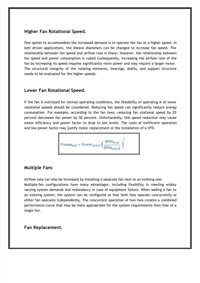
Lower Fan Rotational Speed.
If the fan is oversized for normal operating conditions, the feasibility of operating it at lower
rotational speeds should be considered. Reducing fan speed can significantly reduce energy
consumption. For example, according to the fan laws, reducing fan otational speed by 20
percent decreases fan power by 50 percent. Unfortunately, this speed reduction may cause
motor efficiency and power factor to drop to low levels. The costs of inefficient operation
and low power factor may justify motor replacement or the installation of a VFD.
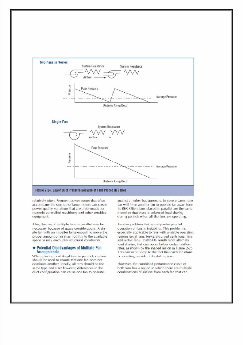
Multiple Fans
Airflow rate can also be increased by installing a separate fan next to an existing one.
Multiple-fan configurations have many advantages, including flexibility in meeting widely
varying system demands and redundancy in case of equipment failure. When adding a fan to
an existing system, the system can be configured so that both fans operate concurrently or
either fan operates independently. The concurrent operation of two fans creates a combined
performance curve that may be more appropriate for the system requirements than that of a
single fan.
Fan Replacement.

8/3/2019 Fans Blowers Nidhi 01
http://slidepdf.com/reader/full/fans-blowers-nidhi-01 26/66
Replacing an existing fan with a different model is also an option. Selecting a new,larger fan
requires consideration of the same factors that are involved in any initial fan selection. A new
fan may be more feasible if the existing one has degraded or requires extensive
refurbishment. In high run-time applications, the purchase of a new fan with an energy-
efficient motor may provide an attractive payback.
FAN TYPES
Basic Principle
Fans can be classified primarily into two different types: axial and centrifugal. Axial fans actlike propellers, generating airflow along the direction of the fan’s axis. Centrifugal fans
generate airflow by accelerating the airstream radially and converting the kinetic energy into
pressure. Axial and centrifugal fans have overlapping capabilities in terms of pressure,
airflow, and efficiency; however, usually they are not interchangeable. Key impacts that
determine which fan type is the most appropriate include technical and nontechnical
attributes. Technical considerations include pressure, airflow rate, efficiency, space
constraints, noise generation, drive configuration, temperature range, variations in operating
conditions, and tolerance to corrosive or particulate-laden airstreams. Nontechnical reasons
include cost, delivery time, availability, and designer/operator familiarity with a fan model.
Understanding the principles of fan selection can be helpful in correcting poor system
performance, especially during retrofit or upgrade opportunities. If noise levels, energy costs,
maintenance requirements, or fan performance do not meet expectations, then a different
type of fan may need to be considered.
Centrifugal Fans
Centrifugal fans are the most commonly used type of industrial fan. Centrifugal fans are
capable of generating high pressures with high efficiencies, and they can be constructed to
accommodate harsh operating conditions. Centrifugal fans have several types of blade shapes,
including forward curved, radial-blade, radial-tip, backward-inclined, backward-curved, and
airfoil. Some centrifugal fan types are capable of serving widely varying operating conditions,
which can be a significant advantage.

8/3/2019 Fans Blowers Nidhi 01
http://slidepdf.com/reader/full/fans-blowers-nidhi-01 27/66
Forward-Curved Blades.
This fan type, shown in Figure 2-1, has blades that curvein the direction of rotation. This fan type is typically
used in applications that require low to medium air
volumes at low pressure. It is characterized by relatively
low efficiency (between 55 and 65 percent).This fan
type can operate at relatively low speeds,which
translates to low levels of noise. Forward curved fans
are commonly selected because of their small size
relative to other fan types.
Stress levels in fans are closely related to operating speed; consequently, forward-curved fansdo not require high-strength design attributes. Their low
operating speed also makes them quiet and wellsuited
for residential heating, ventilation, and air conditioning
(HVAC) applications. A typical performance curve is
shown in Figure 2-2. The dip in the performance curve
represents a stall region that can create operating
problems at low airflow rates.Forward-curved fans are
usually limited to clean service applications. These fans
are typically not constructed for high pressures or harsh
service. Also, fan output is difficult to adjust accurately
(note how the fan curve is somewhat horizontal),and
these fans are not used where airflow must be closely
controlled. Forward-curved fans have a power curve that
increases steadily with airflow toward free delivery; consequently, careful driver selection is
required to avoid overloading the fan motor.
Radial-Blade.
Shown in Figure 2-3, this type is commonly used in applications with low to medium airflow
rates at high pressures. The flat blade shape limits material build-up; consequently, these
fans are capable of handling high-particulate airstreams, including dust, wood chips, and
metal scrap. This fan type is characteristically rugged. The simple design of these fans allows

8/3/2019 Fans Blowers Nidhi 01
http://slidepdf.com/reader/full/fans-blowers-nidhi-01 28/66
many small metalworking shops to custom build units for
special applications. In many cases, the blades can be
inexpensively coated with protective compounds to
improve erosion and corrosion resistance. The large
clearances between the blades also allow this fan to
operate at low airflows without the vibration problems
that usually accompany operating in stall. The
characteristic durability of this fan type is a key reason
why it is considered an industry work horse.
Radial-Tip.
This fan type fills the gap between clean-air fans and
the more rugged radial-blade fans. Radial-tip fans are
characterized by a low angle of attack between the
blades and the incoming air, which promotes low
turbulence. A radial tip fan is shown in fig -2.4
Radial-tip fans have many of the characteristics ofradial-blade fans and are well-suited for use with
airstreams that have small particulates at moderate
concentrations and airstreams with high moisture
contents. Radial-tip fans can have efficiencies up to 75
percent. These fans are commonly used in airborne-
solids handling services because they have large running
clearances. A typical fan curve for radial fans is shown in
Figure 2-5.
Backward-Inclined Fans.
This fan type is characterized by blades that tilt away from the direction of rotation. Within
backward-inclined fans are three different blade shapes: flat, curved, and airfoil. Flat blade
types, shown in Figure 2-6, are more robust. Curved-blade fans tend to be more efficient.

8/3/2019 Fans Blowers Nidhi 01
http://slidepdf.com/reader/full/fans-blowers-nidhi-01 29/66
Airfoil blades, shown in Figure 2-7, are the most efficient of all, capable of achieving
efficiencies exceeding 85 percent. Because airfoil blades rely on the lift created by each
blade, this fan type is highly susceptible to unstable operation because of stall.A consequence
of backward-incline blade orientation is a low angle of impingement with the airstream. This
promotes the accumulation of particulates on the fan blades, which can create performance
problems. Thin airfoil blades are more efficient than the other blade types because of their
lower rotating mass. However, this thinwalled characteristic makes this fan type highly
susceptible to erosion problems. Loss of blade wall thickness can lead to cavity formation in
the blades, which can severely interfere with fan performance.
A common application for backward-inclined fans is
forced-draft service. In these applications, the fan is
exposed to the relatively clean airstream on the
upstream side of the process. The high operating
efficiencies available from this fan type can provide
low system life-cycle costs. A typical performance
curve is shown in Figure 2-8. The motor brake
horsepower increases with airflow for most of the
performance curve but drops off at high airflow rates
because of this non-overloading motor
characteristic,this fan type is often selected when
system behavior at high airflow rates is uncertain.
Axial Fans
The key advantages of axial airflow fans are compactness, low cost, and light weight. Axial
fans are frequently used in exhaust applications where airborne particulate size is small, such
as dust streams, smoke, and steam. Axial fans are also useful in ventilation applications that
8/3/2019 Fans Blowers Nidhi 01
http://slidepdf.com/reader/full/fans-blowers-nidhi-01 30/66
require the ability to generate reverse airflow. Although the fans are typically designed to
generate flow in one direction, they can operate in the reverse direction.This characteristic is
useful when a space may require contaminated air to be exhausted or fresh air to be
supplied.
Axial fans have a severe stall region that makes them particularly unsuitable for systems with
widely varying operating conditions. In this stall region, airflow is insufficient to fill the
blades, causing the fan to operate unstably. The consequences of unstable operation include
annoying noise patterns, inefficient performance, and accelerated drivetrain wear. This
problem of stall can be solved in many axial fans by selecting a fan with an anti-stall device.
These devices alter the airflow patterns around the fan blades, allowing stable fan operation
over the entire range of airflow and pressure. Axial fans must rotate faster than comparable
centrifugal fans to achieve the same airflow capacity. This characteristic makes them noisier
than comparable centrifugal fans; however, the noise signature is dominated by higher
frequencies,which are easier to attenuate.
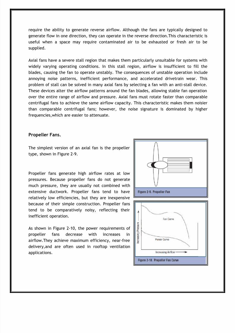
Propeller Fans.
The simplest version of an axial fan is the propeller
type, shown in Figure 2-9.
Propeller fans generate high airflow rates at lowpressures. Because propeller fans do not generate
much pressure, they are usually not combined with
extensive ductwork. Propeller fans tend to have
relatively low efficiencies, but they are inexpensive
because of their simple construction. Propeller fans
tend to be comparatively noisy, reflecting their
inefficient operation.
As shown in Figure 2-10, the power requirements of
propeller fans decrease with increases inairflow.They achieve maximum efficiency, near-free
delivery,and are often used in rooftop ventilation
applications.
8/3/2019 Fans Blowers Nidhi 01
http://slidepdf.com/reader/full/fans-blowers-nidhi-01 31/66
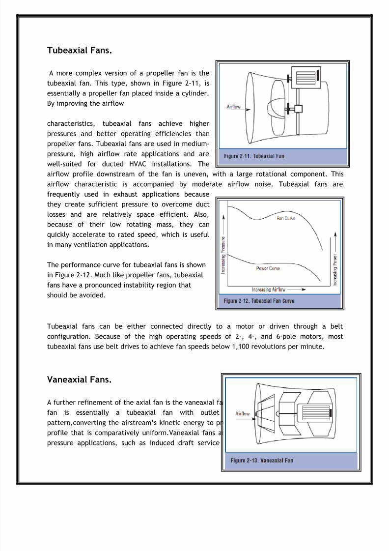
Tubeaxial Fans.
A more complex version of a propeller fan is the
tubeaxial fan. This type, shown in Figure 2-11, is
essentially a propeller fan placed inside a cylinder.By improving the airflow
characteristics, tubeaxial fans achieve higher
pressures and better operating efficiencies than
propeller fans. Tubeaxial fans are used in medium-
pressure, high airflow rate applications and are
well-suited for ducted HVAC installations. The
airflow profile downstream of the fan is uneven, with a large rotational component. This
airflow characteristic is accompanied by moderate airflow noise. Tubeaxial fans are
frequently used in exhaust applications becausethey create sufficient pressure to overcome duct
losses and are relatively space efficient. Also,
because of their low rotating mass, they can
quickly accelerate to rated speed, which is useful
in many ventilation applications.
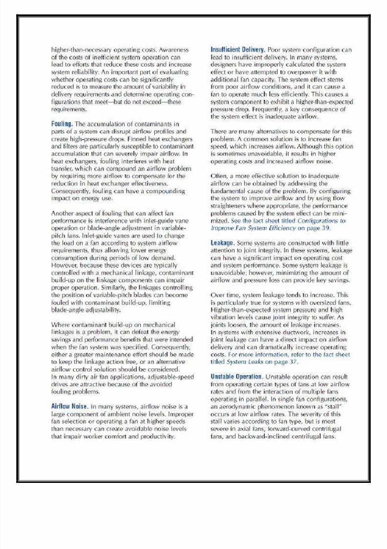
The performance curve for tubeaxial fans is shown
in Figure 2-12. Much like propeller fans, tubeaxial
fans have a pronounced instability region that
should be avoided.
Tubeaxial fans can be either connected directly to a motor or driven through a belt
configuration. Because of the high operating speeds of 2-, 4-, and 6-pole motors, most
tubeaxial fans use belt drives to achieve fan speeds below 1,100 revolutions per minute.
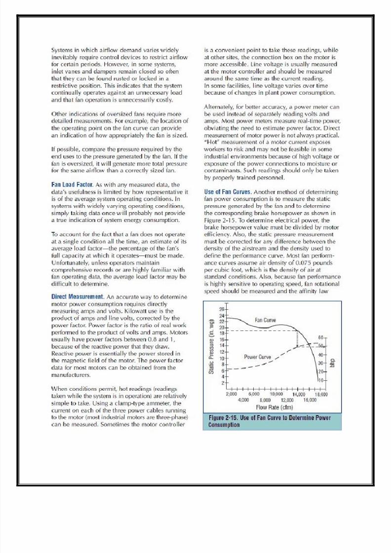
Vaneaxial Fans.
A further refinement of the axial fan is the vaneaxial fan. As shown in Figure 2-13,a vaneaxial
fan is essentially a tubeaxial fan with outlet vanes that improve the airflow
pattern,converting the airstream’s kinetic energy to pressure. These vanes create an airflow
profile that is comparatively uniform.Vaneaxial fans are typically used in medium- to high-
pressure applications, such as induced draft service for a boiler exhaust. Like tubeaxial

8/3/2019 Fans Blowers Nidhi 01
http://slidepdf.com/reader/full/fans-blowers-nidhi-01 32/66
fans,vaneaxial fans tend to have a low rotating
mass,which allows them to achieve operating speed
relatively quickly. This characteristic is useful in
emergency ventilation applications where quick air
removal or supply is required. Also, like other axial
fans, vaneaxial fans can generate flow in reverse
direction, which is also helpful in ventilation
applications. Depending on the circumstances,these
applications may require the supply of fresh air or
the removal of contaminated air.
Vaneaxial fans are often equipped with variablepitch blades, which can be adjusted to change
the angle of attack to the incoming airstream. Variablepitch blades can change the load on
the fan, providing an effective and efficient method of airflow control.As shown in Figure 2-
14, vaneaxial fans have performance curves that have unstable regions to the left of the peakpressure. These fans are highly efficient.
When equipped with airfoil blades and built with small clearances, they can achieve
efficiencies up to 85 percent. Vaneaxial fans are frequently connected directly to a motor
shaft.
Basic Maintenance
Maintenance ItemsCommon maintenance tasks on fan systems include:
Periodic inspection of all system components
Bearing lubrication and replacement
Belt tightening and replacement
Motor repair or replacement
Fan cleaning.
The most costly consequence of improper maintenance is unscheduled downtime. Causes of
this downtime vary according to the demands of the application. Because each system places
particular demands on its air-moving equipment, maintenance requirements vary widely.
Maintenance Schedules
To minimize the amount of unscheduled downtime, basic system maintenance should be
performed at reasonable intervals, the length of which should be determined by either hours
of operation or calendar periods. The maintenance interval should be based on manufacturer
recommendations and experience with fans in similar applications.Factors that should weigh

8/3/2019 Fans Blowers Nidhi 01
http://slidepdf.com/reader/full/fans-blowers-nidhi-01 33/66
into this schedule include the cost of downtime, the cost and the risk of catastrophic failure,
and the availability of back-up equipment. In systems that do not have abnormally severe
operating demands, a typical maintenance schedule would include the items on the checklist.
Belt Inspection.
In belt-driven fans, belts are usually the
most maintenance-intensive part of the
fan assembly. As belts wear, they tend to
lose tension,reducing their power
transmission efficiency. Even new,
properly adjusted belts suffer losses of 5
to10 percent. As belt conditions degrade,
these losses increase. Because noise is one
of the ways in which the energy loss of
belts is manifested, poor belt condition
can add significantly to the ambient noise
level.Belt inspection is particularly
important to the operation of large fans
because of the size of the power losses.
For example, in a 200-horsepower (hp)
fan, a 5 percent decrease in power
transmission efficiency results in a 10-hp
loss, ranslating to $3,270 annually for acontinuously operating system.

8/3/2019 Fans Blowers Nidhi 01
http://slidepdf.com/reader/full/fans-blowers-nidhi-01 34/66

8/3/2019 Fans Blowers Nidhi 01
http://slidepdf.com/reader/full/fans-blowers-nidhi-01 35/66

8/3/2019 Fans Blowers Nidhi 01
http://slidepdf.com/reader/full/fans-blowers-nidhi-01 36/66

8/3/2019 Fans Blowers Nidhi 01
http://slidepdf.com/reader/full/fans-blowers-nidhi-01 37/66
8/3/2019 Fans Blowers Nidhi 01
http://slidepdf.com/reader/full/fans-blowers-nidhi-01 38/66

8/3/2019 Fans Blowers Nidhi 01
http://slidepdf.com/reader/full/fans-blowers-nidhi-01 39/66

8/3/2019 Fans Blowers Nidhi 01
http://slidepdf.com/reader/full/fans-blowers-nidhi-01 40/66
8/3/2019 Fans Blowers Nidhi 01
http://slidepdf.com/reader/full/fans-blowers-nidhi-01 41/66

8/3/2019 Fans Blowers Nidhi 01
http://slidepdf.com/reader/full/fans-blowers-nidhi-01 42/66
8/3/2019 Fans Blowers Nidhi 01
http://slidepdf.com/reader/full/fans-blowers-nidhi-01 43/66

8/3/2019 Fans Blowers Nidhi 01
http://slidepdf.com/reader/full/fans-blowers-nidhi-01 44/66

8/3/2019 Fans Blowers Nidhi 01
http://slidepdf.com/reader/full/fans-blowers-nidhi-01 45/66
8/3/2019 Fans Blowers Nidhi 01
http://slidepdf.com/reader/full/fans-blowers-nidhi-01 46/66
8/3/2019 Fans Blowers Nidhi 01
http://slidepdf.com/reader/full/fans-blowers-nidhi-01 47/66

8/3/2019 Fans Blowers Nidhi 01
http://slidepdf.com/reader/full/fans-blowers-nidhi-01 48/66

8/3/2019 Fans Blowers Nidhi 01
http://slidepdf.com/reader/full/fans-blowers-nidhi-01 49/66

8/3/2019 Fans Blowers Nidhi 01
http://slidepdf.com/reader/full/fans-blowers-nidhi-01 50/66
8/3/2019 Fans Blowers Nidhi 01
http://slidepdf.com/reader/full/fans-blowers-nidhi-01 51/66

8/3/2019 Fans Blowers Nidhi 01
http://slidepdf.com/reader/full/fans-blowers-nidhi-01 52/66

8/3/2019 Fans Blowers Nidhi 01
http://slidepdf.com/reader/full/fans-blowers-nidhi-01 53/66

8/3/2019 Fans Blowers Nidhi 01
http://slidepdf.com/reader/full/fans-blowers-nidhi-01 54/66
8/3/2019 Fans Blowers Nidhi 01
http://slidepdf.com/reader/full/fans-blowers-nidhi-01 55/66

8/3/2019 Fans Blowers Nidhi 01
http://slidepdf.com/reader/full/fans-blowers-nidhi-01 56/66
8/3/2019 Fans Blowers Nidhi 01
http://slidepdf.com/reader/full/fans-blowers-nidhi-01 57/66

8/3/2019 Fans Blowers Nidhi 01
http://slidepdf.com/reader/full/fans-blowers-nidhi-01 58/66

8/3/2019 Fans Blowers Nidhi 01
http://slidepdf.com/reader/full/fans-blowers-nidhi-01 59/66

8/3/2019 Fans Blowers Nidhi 01
http://slidepdf.com/reader/full/fans-blowers-nidhi-01 60/66
8/3/2019 Fans Blowers Nidhi 01
http://slidepdf.com/reader/full/fans-blowers-nidhi-01 61/66
8/3/2019 Fans Blowers Nidhi 01
http://slidepdf.com/reader/full/fans-blowers-nidhi-01 62/66

8/3/2019 Fans Blowers Nidhi 01
http://slidepdf.com/reader/full/fans-blowers-nidhi-01 63/66
8/3/2019 Fans Blowers Nidhi 01
http://slidepdf.com/reader/full/fans-blowers-nidhi-01 64/66

8/3/2019 Fans Blowers Nidhi 01
http://slidepdf.com/reader/full/fans-blowers-nidhi-01 65/66

8/3/2019 Fans Blowers Nidhi 01
http://slidepdf.com/reader/full/fans-blowers-nidhi-01 66/66