Embed Size (px)
Citation preview

Fanuc Focas HSSB Driver
©2016 Kepware, Inc.

Fanuc Focas HSSB Driver
Table of ContentsTable of Contents 2Fanuc Focas HSSB Driver Help 4
Overview 4
External Dependencies 4
Install Focas Library 4
Device Setup 5Communications Parameters 6
Optimizing Fanuc Focas HSSB Communications 7
Data Types Description 8
Address Descriptions 9Series 15i 9
Series 16i 10
Series 18i 12
Series 21i 13
Power Mate i 15
Open 17
Tool Offset 18
Workpiece Zero Offset 19
Error Descriptions 21Address Validation 21
Address <address> is out of range for the specified device or register. 21
Array size is out of range for address <address>. 21
Array support is not available for the specified address: <address>. 21
Data Type <type> is not valid for device address <address>. 22
Device address <address> contains a syntax error. 22
Device address <address> is read only. 22
Missing address. 22
Device Status Messages. 22
Device <device name> is not responding. 22
Unable to write to <address> on device <device name>. 23
General Driver Messages 23
Could not acquire library handle for device <channel.device>. FWLIB error: <code>. 23
Could not read one or more vacant macros in range starting at <address> on device <device>. 24
Could not set request timeout for device <channel.device>. FWLIB error: <code>. 24
Device ID <node> is too large for device <channel.device>. The maximum allowed is <max. node>. 24
Failed to read maximum Node ID for device <channel.device>. FWLIB error: <code>. 24
www. kepware.com
2
Fanuc Focas HSSB Driver
Read error occurred for address starting at <address> on device <channel.device>. FWLIB error:<code>. 25
Unable to start the Fanuc Focas Data Window Library services. 25
Write error occurred for address <address> on device <channel.device>. FWLIB error: <code>. 25
Focas1 Data Window Library Codes 27
Index 28
www. kepware.com
3
Fanuc Focas HSSB Driver
Fanuc Focas HSSB Driver HelpHelp version 1.038
CONTENTS
OverviewWhat is the Fanuc Focas HSSB Driver?
Device SetupHow do I configure a device for use with this driver?
Optimizing Fanuc Focas HSSB CommunicationsHow do I get the best performance from the Fanuc Focas HSSB Driver?
Data Types DescriptionWhat data types does this driver support?
Address DescriptionsHow do I address a data location on a Fanuc Focas1/Focas2 device?
Error DescriptionsWhat error messages does the Fanuc Focas HSSB Driver produce?
OverviewThe Fanuc Focas HSSB Driver provides a reliable way to connect Fanuc Focas High-Speed Serial Bus (HSSB)controllers to OPC Client applications, including HMI, SCADA, Historian, MES, ERP, and countless customapplications. It is intended for use with Fanuc Focas1 Programmable Logic Controllers.
Note: For more information on the additional hardware that is required for use with this driver, refer to ExternalDependencies.
External DependenciesThis driver has external dependencies. For this driver to communicate with the hardware, FANUC CNCFocas1/Ethernet Library (part number A02B-0207-K732) or FANUC Focas2 Library (part number A02B-0207-K737) must be installed on the system. Although the library does not need to be installed to create a serverproject, the project will not run without it.
Note: The Focas2 Library combines both Ethernet and HSSB capabilities and can be purchased from the FANUCdistributor or by calling 1-888-326-8287. Choose CNC, PARTS to place the order, then request the part number.
Important: An HSSB interface card must be installed in the host computer and connected to the controller withthe appropriate fiber optic cable.
Install Focas LibraryThis driver requires the Focas library to communicate with the hardware (FANUC CNC Focas1/Ethernet Library(part number A02B-0207-K732) or FANUC Focas2 Library (part number A02B-0207-K737). Follow these steps toinstall the library:
1. Obtain the library from the distributor (typically Fwlib*.zip).
2. Move or paste the Fwlib*.zip file to the Windows/System32 folder.
3. Unzip / extract the contents of the Fwlib*.zip in the Windows/System32 folder.
4. Reboot the computer.
5. Run the OPC server and configure a Focas1 project.
See Also: External Dependencies
www. kepware.com
4
Fanuc Focas HSSB Driver
Device SetupSupported DevicesThis driver can communicate with controllers that are compatible with the Focas1 or Focas2 CNC/PMC datawindow control libraries. This includes, but is not limited to, the following:
Series 0iSeries 15Series 15iSeries 16Series 16iSeries 18Series 18iSeries 21Series 21iSeries 30iSeries 31iSeries 32iPower Mate iOpen Addressing
Connection TimeoutThis parameter specifies the amount of time that the driver will wait for a connection to be made with a device.The connection time depends on network load, and may vary with each connection attempt. The valid range is 1to 60 seconds. The default setting is 3 seconds.
Request TimeoutThis parameter specifies the amount of time that the driver will wait for a response from the device before givingup and going on to the next request. Longer timeouts will only affect performance if a device is not responding.The valid range is 100 to 9999 milliseconds. The default setting is 1000 milliseconds.
Retry AttemptsThis parameter specifies the number of times that the driver will retry a message before giving up and going onto the next message. The valid range is 1 to 10. The default setting is 3.
Device IDThis parameter specifies the controller's HSSB node number. Up to 8 devices may be defined on a given channel.The valid range is 0 to 65535. The default setting is 0.
www. kepware.com
5
Fanuc Focas HSSB Driver
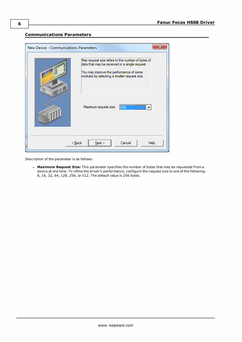
Communications Parameters
Description of the parameter is as follows:
l Maximum Request Size: This parameter specifies the number of bytes that may be requested from adevice at one time. To refine the driver's performance, configure the request size to one of the following:8, 16, 32, 64, 128, 256, or 512. The default value is 256 bytes.
www. kepware.com
6
Fanuc Focas HSSB Driver
Optimizing Fanuc Focas HSSB CommunicationsThe Fanuc Focas HSSB Driver has been designed to provide the best performance with the least amount of impacton the system's overall performance. While the driver is fast, there are a couple of guidelines that can be used tocontrol and optimize the application and gain maximum performance.
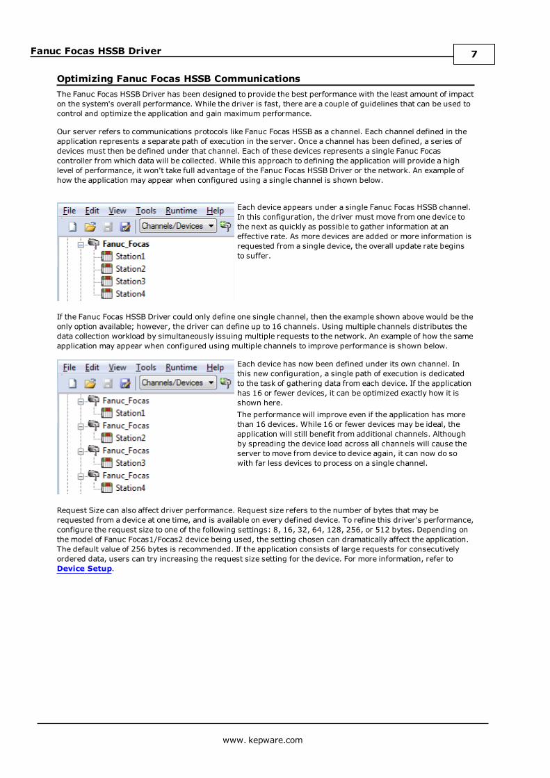
Our server refers to communications protocols like Fanuc Focas HSSB as a channel. Each channel defined in theapplication represents a separate path of execution in the server. Once a channel has been defined, a series ofdevices must then be defined under that channel. Each of these devices represents a single Fanuc Focascontroller from which data will be collected. While this approach to defining the application will provide a highlevel of performance, it won't take full advantage of the Fanuc Focas HSSB Driver or the network. An example ofhow the application may appear when configured using a single channel is shown below.
Each device appears under a single Fanuc Focas HSSB channel.In this configuration, the driver must move from one device tothe next as quickly as possible to gather information at aneffective rate. As more devices are added or more information isrequested from a single device, the overall update rate beginsto suffer.
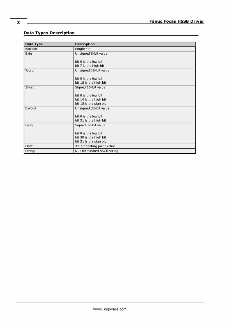
If the Fanuc Focas HSSB Driver could only define one single channel, then the example shown above would be theonly option available; however, the driver can define up to 16 channels. Using multiple channels distributes thedata collection workload by simultaneously issuing multiple requests to the network. An example of how the sameapplication may appear when configured using multiple channels to improve performance is shown below.
Each device has now been defined under its own channel. Inthis new configuration, a single path of execution is dedicatedto the task of gathering data from each device. If the applicationhas 16 or fewer devices, it can be optimized exactly how it isshown here.The performance will improve even if the application has morethan 16 devices. While 16 or fewer devices may be ideal, theapplication will still benefit from additional channels. Althoughby spreading the device load across all channels will cause theserver to move from device to device again, it can now do sowith far less devices to process on a single channel.
Request Size can also affect driver performance. Request size refers to the number of bytes that may berequested from a device at one time, and is available on every defined device. To refine this driver's performance,configure the request size to one of the following settings: 8, 16, 32, 64, 128, 256, or 512 bytes. Depending onthe model of Fanuc Focas1/Focas2 device being used, the setting chosen can dramatically affect the application.The default value of 256 bytes is recommended. If the application consists of large requests for consecutivelyordered data, users can try increasing the request size setting for the device. For more information, refer toDevice Setup.
www. kepware.com
7
Fanuc Focas HSSB Driver
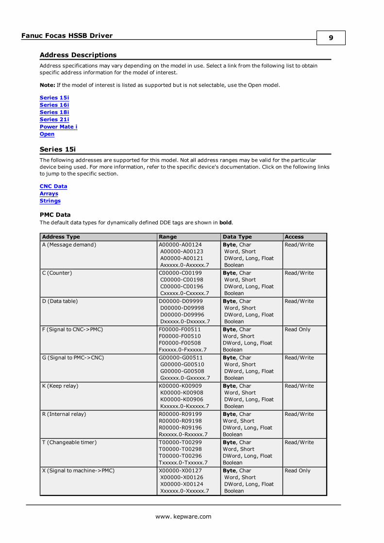
Data Types Description
Data Type DescriptionBoolean Single bitByte Unsigned 8-bit value
bit 0 is the low bitbit 7 is the high bit
Word Unsigned 16-bit value
bit 0 is the low bitbit 15 is the high bit
Short Signed 16-bit value
bit 0 is the low bitbit 14 is the high bitbit 15 is the sign bit
DWord Unsigned 32-bit value
bit 0 is the low bitbit 31 is the high bit
Long Signed 32-bit value
bit 0 is the low bitbit 30 is the high bitbit 31 is the sign bit
Float 32-bit floating point valueString Null terminated ASCII string
www. kepware.com
8
Fanuc Focas HSSB Driver
Address DescriptionsAddress specifications may vary depending on the model in use. Select a link from the following list to obtainspecific address information for the model of interest.
Note: If the model of interest is listed as supported but is not selectable, use the Open model.
Series 15iSeries 16iSeries 18iSeries 21iPower Mate iOpen
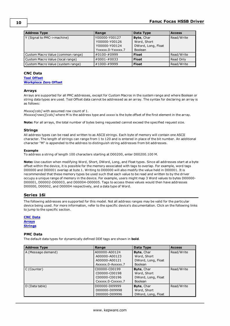
Series 15iThe following addresses are supported for this model. Not all address ranges may be valid for the particulardevice being used. For more information, refer to the specific device's documentation. Click on the following linksto jump to the specific section.
CNC DataArraysStrings
PMC DataThe default data types for dynamically defined DDE tags are shown in bold.
Address Type Range Data Type AccessA (Message demand) A00000-A00124
A00000-A00123A00000-A00121Axxxxx.0-Axxxxx.7
Byte, CharWord, ShortDWord, Long, FloatBoolean
Read/Write
C (Counter) C00000-C00199C00000-C00198C00000-C00196Cxxxxx.0-Cxxxxx.7
Byte, CharWord, ShortDWord, Long, FloatBoolean
Read/Write
D (Data table) D00000-D09999D00000-D09998D00000-D09996Dxxxxx.0-Dxxxxx.7
Byte, CharWord, ShortDWord, Long, FloatBoolean
Read/Write
F (Signal to CNC->PMC) F00000-F00511F00000-F00510F00000-F00508Fxxxxx.0-Fxxxxx.7
Byte, CharWord, ShortDWord, Long, FloatBoolean
Read Only
G (Signal to PMC->CNC) G00000-G00511G00000-G00510G00000-G00508Gxxxxx.0-Gxxxxx.7
Byte, CharWord, ShortDWord, Long, FloatBoolean
Read/Write
K (Keep relay) K00000-K00909K00000-K00908K00000-K00906Kxxxxx.0-Kxxxxx.7
Byte, CharWord, ShortDWord, Long, FloatBoolean
Read/Write
R (Internal relay) R00000-R09199R00000-R09198R00000-R09196Rxxxxx.0-Rxxxxx.7
Byte, CharWord, ShortDWord, Long, FloatBoolean
Read/Write
T (Changeable timer) T00000-T00299T00000-T00298T00000-T00296Txxxxx.0-Txxxxx.7
Byte, CharWord, ShortDWord, Long, FloatBoolean
Read/Write
X (Signal to machine->PMC) X00000-X00127X00000-X00126X00000-X00124Xxxxxx.0-Xxxxxx.7
Byte, CharWord, ShortDWord, Long, FloatBoolean
Read Only
www. kepware.com
9
Fanuc Focas HSSB Driver
Address Type Range Data Type AccessY (Signal to PMC->machine) Y00000-Y00127
Y00000-Y00126Y00000-Y00124Yxxxxx.0-Yxxxxx.7
Byte, CharWord, ShortDWord, Long, FloatBoolean
Read/Write
Custom Macro Value (common range) #0100-#0999 Float Read/WriteCustom Macro Value (local range) #0001-#0033 Float Read OnlyCustom Macro Value (system range) #1000-#9999 Float Read/Write
CNC DataTool OffsetWorkpiece Zero Offset
ArraysArrays are supported for all PMC addresses, except for Custom Macros in the system range and where Boolean orstring data types are used. Tool Offset data cannot be addressed as an array. The syntax for declaring an array isas follows:
Mxxxx[cols] with assumed row count of 1.Mxxxxx[rows][cols] where M is the address type and xxxxx is the byte offset of the first element in the array.
Note: For all arrays, the total number of bytes being requested cannot exceed the specified request size.
StringsAll address types can be read and written to as ASCII strings. Each byte of memory will contain one ASCIIcharacter. The length of strings can range from 1 to 120 and is entered in place of the bit number. An additionalcharacter "M" is appended to the address to distinguish string addresses from bit addresses.
ExampleTo address a string of length 100 characters starting at D00200, enter D00200.100 M.
Note: Use caution when modifying Word, Short, DWord, Long, and Float types. Since all addresses start at a byteoffset within the device, it is possible for the memory associated with tags to overlap. For example, word tagsD00000 and D00001 overlap at byte 1. Writing to D00000 will also modify the value held in D00001. It isrecommended that these memory types be used such that each value to be read and written to by the driveroccupy a unique range of memory in the device. For example, users might map 3 Word values to bytes D00000-D00001, D00002-D00003, and D00004-D00005. Tags to access these values would then have addressesD00000, D00002, and D00004 respectively, and a data type of Word.
Series 16iThe following addresses are supported for this model. Not all address ranges may be valid for the particulardevice being used. For more information, refer to the specific device's documentation. Click on the following linksto jump to the specific section.
CNC DataArraysStrings
PMC DataThe default data types for dynamically defined DDE tags are shown in bold.
Address Type Range Data Type AccessA (Message demand) A00000-A00124
A00000-A00123A00000-A00121Axxxxx.0-Axxxxx.7
Byte, CharWord, ShortDWord, Long, FloatBoolean
Read/Write
C (Counter) C00000-C00199C00000-C00198C00000-C00196Cxxxxx.0-Cxxxxx.7
Byte, CharWord, ShortDWord, Long, FloatBoolean
Read/Write
D (Data table) D00000-D09999D00000-D09998D00000-D09996
Byte, CharWord, ShortDWord, Long, Float
Read/Write
www. kepware.com
10
Fanuc Focas HSSB Driver
Address Type Range Data Type AccessDxxxxx.0-Dxxxxx.7 Boolean
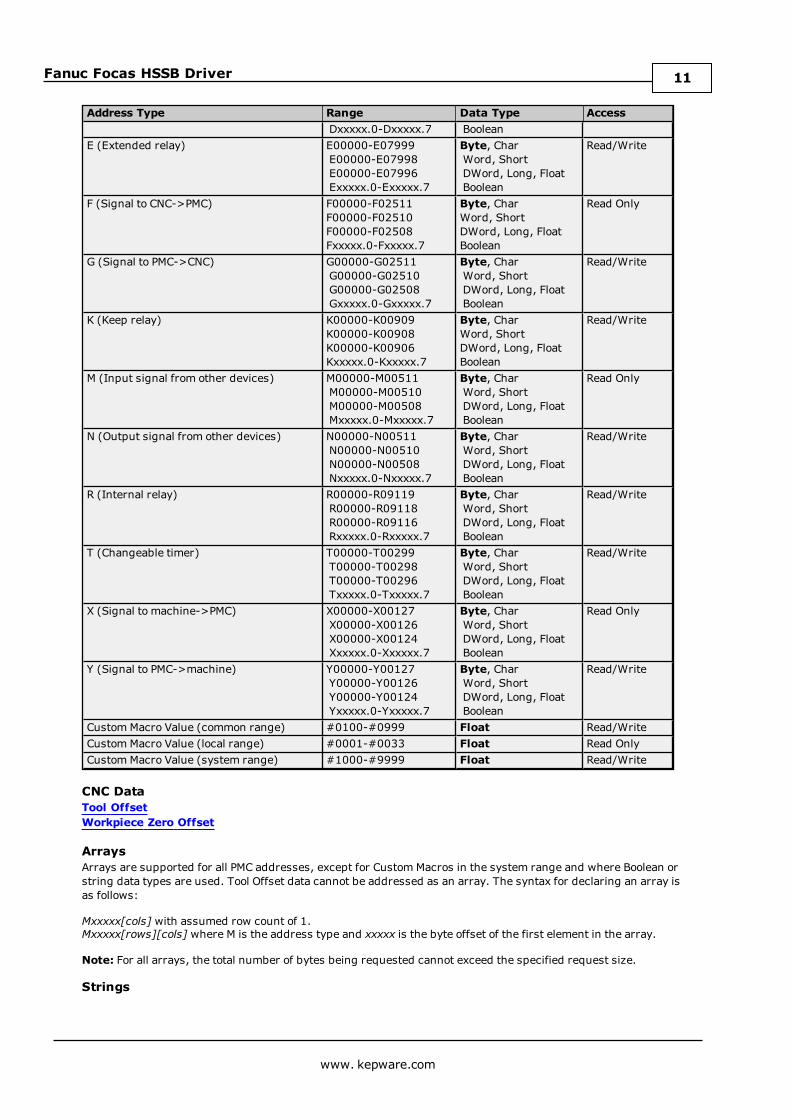
E (Extended relay) E00000-E07999E00000-E07998E00000-E07996Exxxxx.0-Exxxxx.7
Byte, CharWord, ShortDWord, Long, FloatBoolean
Read/Write
F (Signal to CNC->PMC) F00000-F02511F00000-F02510F00000-F02508Fxxxxx.0-Fxxxxx.7
Byte, CharWord, ShortDWord, Long, FloatBoolean
Read Only
G (Signal to PMC->CNC) G00000-G02511G00000-G02510G00000-G02508Gxxxxx.0-Gxxxxx.7
Byte, CharWord, ShortDWord, Long, FloatBoolean
Read/Write
K (Keep relay) K00000-K00909K00000-K00908K00000-K00906Kxxxxx.0-Kxxxxx.7
Byte, CharWord, ShortDWord, Long, FloatBoolean
Read/Write
M (Input signal from other devices) M00000-M00511M00000-M00510M00000-M00508Mxxxxx.0-Mxxxxx.7
Byte, CharWord, ShortDWord, Long, FloatBoolean
Read Only
N (Output signal from other devices) N00000-N00511N00000-N00510N00000-N00508Nxxxxx.0-Nxxxxx.7
Byte, CharWord, ShortDWord, Long, FloatBoolean
Read/Write
R (Internal relay) R00000-R09119R00000-R09118R00000-R09116Rxxxxx.0-Rxxxxx.7
Byte, CharWord, ShortDWord, Long, FloatBoolean
Read/Write
T (Changeable timer) T00000-T00299T00000-T00298T00000-T00296Txxxxx.0-Txxxxx.7
Byte, CharWord, ShortDWord, Long, FloatBoolean
Read/Write
X (Signal to machine->PMC) X00000-X00127X00000-X00126X00000-X00124Xxxxxx.0-Xxxxxx.7
Byte, CharWord, ShortDWord, Long, FloatBoolean
Read Only
Y (Signal to PMC->machine) Y00000-Y00127Y00000-Y00126Y00000-Y00124Yxxxxx.0-Yxxxxx.7
Byte, CharWord, ShortDWord, Long, FloatBoolean
Read/Write
Custom Macro Value (common range) #0100-#0999 Float Read/WriteCustom Macro Value (local range) #0001-#0033 Float Read OnlyCustom Macro Value (system range) #1000-#9999 Float Read/Write
CNC DataTool OffsetWorkpiece Zero Offset
ArraysArrays are supported for all PMC addresses, except for Custom Macros in the system range and where Boolean orstring data types are used. Tool Offset data cannot be addressed as an array. The syntax for declaring an array isas follows:
Mxxxxx[cols] with assumed row count of 1.Mxxxxx[rows][cols] where M is the address type and xxxxx is the byte offset of the first element in the array.
Note: For all arrays, the total number of bytes being requested cannot exceed the specified request size.
Strings
www. kepware.com
11

Fanuc Focas HSSB Driver
All address types can be read and written to as ASCII strings. Each byte of memory will contain one ASCIIcharacter. The length of strings can range from 1 to 120 and is entered in place of the bit number. An additionalcharacter "M" is appended to the address to distinguish string addresses from bit addresses.
ExampleTo address a string of length 100 characters starting at D00200, enter D00200.100 M.
Note: Use caution when modifying Word, Short, DWord, Long, and Float types. Since all addresses start at a byteoffset within the device, it is possible for the memory associated with tags to overlap. For example, word tagsD00000 and D00001 overlap at byte 1. Writing to D00000 will also modify the value held in D00001. It isrecommended that these memory types be used such that each value to be read and written to by the driveroccupy a unique range of memory in the device. For example, users might map 3 Word values to bytes D00000-D00001, D00002-D00003, and D00004-D00005. Tags to access these values would then have addressesD00000, D00002, and D00004 respectively, and a data type of Word.
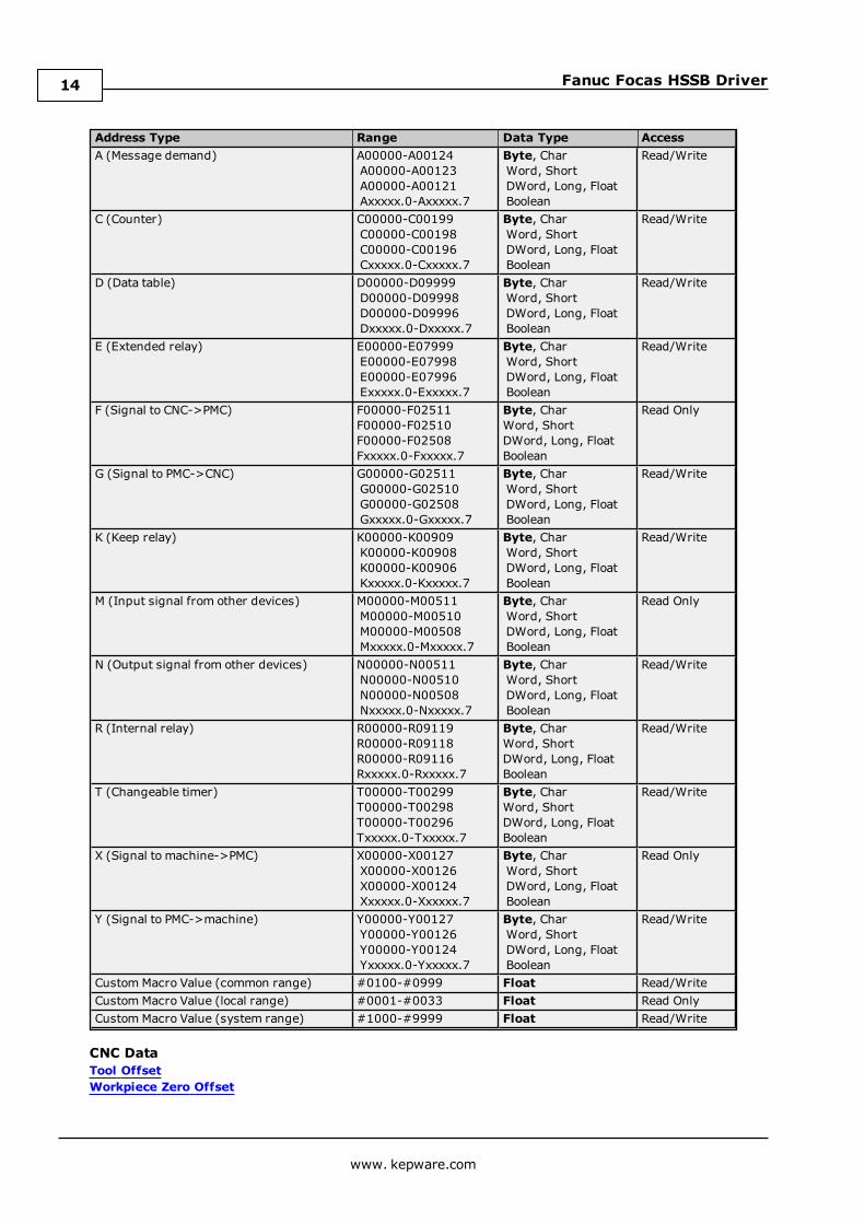
Series 18iThe following addresses are supported for this model. Not all address ranges may be valid for the particulardevice being used. For more information, refer to the specific device's documentation. Click on the following linksto jump to the specific section.
CNC DataArraysStrings
PMC DataThe default data types for dynamically defined DDE tags are shown in bold.
Address Type Range Data Type AccessA (Message demand) A00000-A00124
A00000-A00123A00000-A00121Axxxxx.0-Axxxxx.7
Byte, CharWord, ShortDWord, Long, FloatBoolean
Read/Write
C (Counter) C00000-C00199C00000-C00198C00000-C00196Cxxxxx.0-Cxxxxx.7
Byte, CharWord, ShortDWord, Long, FloatBoolean
Read/Write
D (Data table) D00000-D09999D00000-D09998D00000-D09996Dxxxxx.0-Dxxxxx.7
Byte, CharWord, ShortDWord, Long, FloatBoolean
Read/Write
E (Extended relay) E00000-E07999E00000-E07998E00000-E07996Exxxxx.0-Exxxxx.7
Byte, CharWord, ShortDWord, Long, FloatBoolean
Read/Write
F (Signal to CNC->PMC) F00000-F02511F00000-F02510F00000-F02508Fxxxxx.0-Fxxxxx.7
Byte, CharWord, ShortDWord, Long, FloatBoolean
Read Only
G (Signal to PMC->CNC) G00000-G02511G00000-G02510G00000-G02508Gxxxxx.0-Gxxxxx.7
Byte, CharWord, ShortDWord, Long, FloatBoolean
Read/Write
K (Keep relay) K00000-K00909K00000-K00908K00000-K00906Kxxxxx.0-Kxxxxx.7
Byte, CharWord, ShortDWord, Long, FloatBoolean
Read/Write
M (Input signal from other devices) M00000-M00511M00000-M00510M00000-M00508Mxxxxx.0-Mxxxxx.7
Byte, CharWord, ShortDWord, Long, FloatBoolean
Read Only
N (Output signal from other devices) N00000-N00511N00000-N00510N00000-N00508
Byte, CharWord, ShortDWord, Long, Float
Read/Write
www. kepware.com
12
Fanuc Focas HSSB Driver
Address Type Range Data Type AccessNxxxxx.0-Nxxxxx.7 Boolean
R (Internal relay) R00000-R09119R00000-R09118R00000-R09116Rxxxxx.0-Rxxxxx.7
Byte, CharWord, ShortDWord, Long, FloatBoolean
Read/Write
T (Changeable timer) T00000-T00299T00000-T00298T00000-T00296Txxxxx.0-Txxxxx.7
Byte, CharWord, ShortDWord, Long, FloatBoolean
Read/Write
X (Signal to machine->PMC) X00000-X00127X00000-X00126X00000-X00124Xxxxxx.0-Xxxxxx.7
Byte, CharWord, ShortDWord, Long, FloatBoolean
Read Only
Y (Signal to PMC->machine) Y00000-Y00127Y00000-Y00126Y00000-Y00124Yxxxxx.0-Yxxxxx.7
Byte, CharWord, ShortDWord, Long, FloatBoolean
Read/Write
Custom Macro Value (common range) #0100-#0999 Float Read/WriteCustom Macro Value (local range) #0001-#0033 Float Read OnlyCustom Macro Value (system range) #1000-#9999 Float Read/Write
CNC DataTool OffsetWorkpiece Zero Offset
ArraysArrays are supported for all PMC addresses, except for Custom Macros in the system range and where Boolean orstring data types are used. Tool Offset data cannot be addressed as an array. The syntax for declaring an array isas follows:
Mxxxxx[cols] with assumed row count of 1.Mxxxxx[rows][cols] where M is the address type and xxxxx is the byte offset of the first element in the array.
Note: For all arrays, the total number of bytes being requested cannot exceed the specified request size.
StringsAll address types can be read and written to as ASCII strings. Each byte of memory will contain one ASCIIcharacter. The length of strings can range from 1 to 120 and is entered in place of the bit number. An additionalcharacter "M" is appended to the address to distinguish string addresses from bit addresses.
ExampleTo address a string of length 100 characters starting at D00200, enter D00200.100 M.
Note: Use caution when modifying Word, Short, DWord, Long, and Float types. Since all addresses start at a byteoffset within the device, it is possible for the memory associated with tags to overlap. For example, word tagsD00000 and D00001 overlap at byte 1. Writing to D00000 will also modify the value held in D00001. It isrecommended that these memory types be used such that each value to be read and written to by the driveroccupy a unique range of memory in the device. For example, users might map 3 Word values to bytes D00000-D00001, D00002-D00003, and D00004-D00005. Tags to access these values would then have addressesD00000, D00002, and D00004 respectively, and a data type of Word.
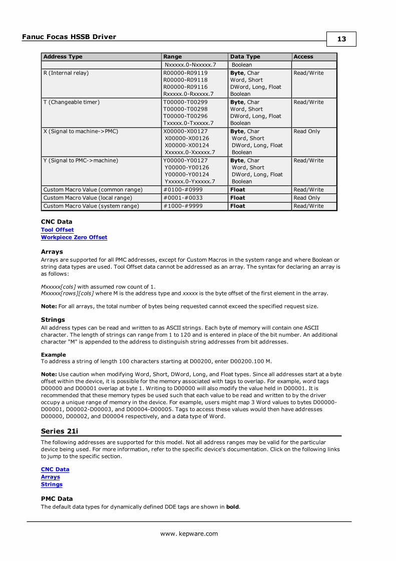
Series 21iThe following addresses are supported for this model. Not all address ranges may be valid for the particulardevice being used. For more information, refer to the specific device's documentation. Click on the following linksto jump to the specific section.
CNC DataArraysStrings
PMC DataThe default data types for dynamically defined DDE tags are shown in bold.
www. kepware.com
13
Fanuc Focas HSSB Driver
Address Type Range Data Type AccessA (Message demand) A00000-A00124
A00000-A00123A00000-A00121Axxxxx.0-Axxxxx.7
Byte, CharWord, ShortDWord, Long, FloatBoolean
Read/Write
C (Counter) C00000-C00199C00000-C00198C00000-C00196Cxxxxx.0-Cxxxxx.7
Byte, CharWord, ShortDWord, Long, FloatBoolean
Read/Write
D (Data table) D00000-D09999D00000-D09998D00000-D09996Dxxxxx.0-Dxxxxx.7
Byte, CharWord, ShortDWord, Long, FloatBoolean
Read/Write
E (Extended relay) E00000-E07999E00000-E07998E00000-E07996Exxxxx.0-Exxxxx.7
Byte, CharWord, ShortDWord, Long, FloatBoolean
Read/Write
F (Signal to CNC->PMC) F00000-F02511F00000-F02510F00000-F02508Fxxxxx.0-Fxxxxx.7
Byte, CharWord, ShortDWord, Long, FloatBoolean
Read Only
G (Signal to PMC->CNC) G00000-G02511G00000-G02510G00000-G02508Gxxxxx.0-Gxxxxx.7
Byte, CharWord, ShortDWord, Long, FloatBoolean
Read/Write
K (Keep relay) K00000-K00909K00000-K00908K00000-K00906Kxxxxx.0-Kxxxxx.7
Byte, CharWord, ShortDWord, Long, FloatBoolean
Read/Write
M (Input signal from other devices) M00000-M00511M00000-M00510M00000-M00508Mxxxxx.0-Mxxxxx.7
Byte, CharWord, ShortDWord, Long, FloatBoolean
Read Only
N (Output signal from other devices) N00000-N00511N00000-N00510N00000-N00508Nxxxxx.0-Nxxxxx.7
Byte, CharWord, ShortDWord, Long, FloatBoolean
Read/Write
R (Internal relay) R00000-R09119R00000-R09118R00000-R09116Rxxxxx.0-Rxxxxx.7
Byte, CharWord, ShortDWord, Long, FloatBoolean
Read/Write
T (Changeable timer) T00000-T00299T00000-T00298T00000-T00296Txxxxx.0-Txxxxx.7
Byte, CharWord, ShortDWord, Long, FloatBoolean
Read/Write
X (Signal to machine->PMC) X00000-X00127X00000-X00126X00000-X00124Xxxxxx.0-Xxxxxx.7
Byte, CharWord, ShortDWord, Long, FloatBoolean
Read Only
Y (Signal to PMC->machine) Y00000-Y00127Y00000-Y00126Y00000-Y00124Yxxxxx.0-Yxxxxx.7
Byte, CharWord, ShortDWord, Long, FloatBoolean
Read/Write
Custom Macro Value (common range) #0100-#0999 Float Read/WriteCustom Macro Value (local range) #0001-#0033 Float Read OnlyCustom Macro Value (system range) #1000-#9999 Float Read/Write
CNC DataTool OffsetWorkpiece Zero Offset
www. kepware.com
14
Fanuc Focas HSSB Driver
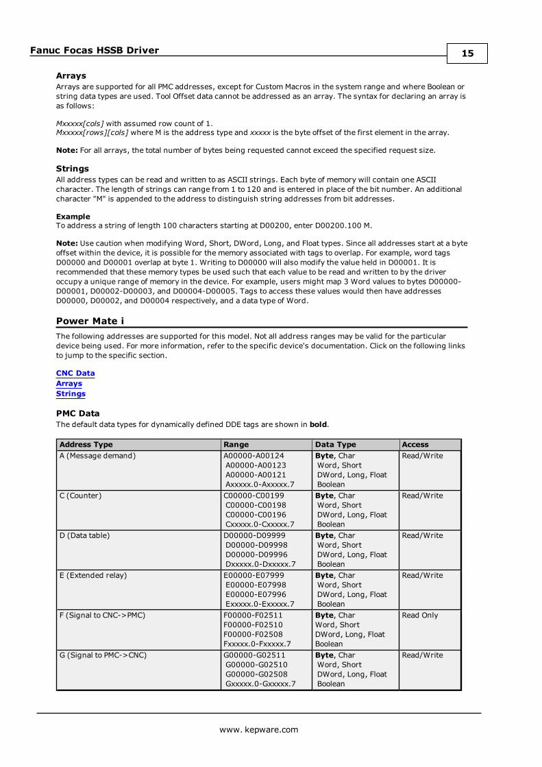
ArraysArrays are supported for all PMC addresses, except for Custom Macros in the system range and where Boolean orstring data types are used. Tool Offset data cannot be addressed as an array. The syntax for declaring an array isas follows:
Mxxxxx[cols] with assumed row count of 1.Mxxxxx[rows][cols] where M is the address type and xxxxx is the byte offset of the first element in the array.
Note: For all arrays, the total number of bytes being requested cannot exceed the specified request size.
StringsAll address types can be read and written to as ASCII strings. Each byte of memory will contain one ASCIIcharacter. The length of strings can range from 1 to 120 and is entered in place of the bit number. An additionalcharacter "M" is appended to the address to distinguish string addresses from bit addresses.
ExampleTo address a string of length 100 characters starting at D00200, enter D00200.100 M.
Note: Use caution when modifying Word, Short, DWord, Long, and Float types. Since all addresses start at a byteoffset within the device, it is possible for the memory associated with tags to overlap. For example, word tagsD00000 and D00001 overlap at byte 1. Writing to D00000 will also modify the value held in D00001. It isrecommended that these memory types be used such that each value to be read and written to by the driveroccupy a unique range of memory in the device. For example, users might map 3 Word values to bytes D00000-D00001, D00002-D00003, and D00004-D00005. Tags to access these values would then have addressesD00000, D00002, and D00004 respectively, and a data type of Word.
Power Mate iThe following addresses are supported for this model. Not all address ranges may be valid for the particulardevice being used. For more information, refer to the specific device's documentation. Click on the following linksto jump to the specific section.
CNC DataArraysStrings
PMC DataThe default data types for dynamically defined DDE tags are shown in bold.
Address Type Range Data Type AccessA (Message demand) A00000-A00124
A00000-A00123A00000-A00121Axxxxx.0-Axxxxx.7
Byte, CharWord, ShortDWord, Long, FloatBoolean
Read/Write
C (Counter) C00000-C00199C00000-C00198C00000-C00196Cxxxxx.0-Cxxxxx.7
Byte, CharWord, ShortDWord, Long, FloatBoolean
Read/Write
D (Data table) D00000-D09999D00000-D09998D00000-D09996Dxxxxx.0-Dxxxxx.7
Byte, CharWord, ShortDWord, Long, FloatBoolean
Read/Write
E (Extended relay) E00000-E07999E00000-E07998E00000-E07996Exxxxx.0-Exxxxx.7
Byte, CharWord, ShortDWord, Long, FloatBoolean
Read/Write
F (Signal to CNC->PMC) F00000-F02511F00000-F02510F00000-F02508Fxxxxx.0-Fxxxxx.7
Byte, CharWord, ShortDWord, Long, FloatBoolean
Read Only
G (Signal to PMC->CNC) G00000-G02511G00000-G02510G00000-G02508Gxxxxx.0-Gxxxxx.7
Byte, CharWord, ShortDWord, Long, FloatBoolean
Read/Write
www. kepware.com
15

Fanuc Focas HSSB Driver
Address Type Range Data Type AccessK (Keep relay) K00000-K00909
K00000-K00908K00000-K00906Kxxxxx.0-Kxxxxx.7
Byte, CharWord, ShortDWord, Long, FloatBoolean
Read/Write
M (Input signal from other devices) M00000-M00511M00000-M00510M00000-M00508Mxxxxx.0-Mxxxxx.7
Byte, CharWord, ShortDWord, Long, FloatBoolean
Read Only
N (Output signal from other devices) N00000-N00511N00000-N00510N00000-N00508Nxxxxx.0-Nxxxxx.7
Byte, CharWord, ShortDWord, Long, FloatBoolean
Read/Write
R (Internal relay) R00000-R09119R00000-R09118R00000-R09116Rxxxxx.0-Rxxxxx.7
Byte, CharWord, ShortDWord, Long, FloatBoolean
Read/Write
T (Changeable timer) T00000-T00299T00000-T00298T00000-T00296Txxxxx.0-Txxxxx.7
Byte, CharWord, ShortDWord, Long, FloatBoolean
Read/Write
X (Signal to machine->PMC) X00000-X00127X00000-X00126X00000-X00124Xxxxxx.0-Xxxxxx.7
Byte, CharWord, ShortDWord, Long, FloatBoolean
Read Only
Y (Signal to PMC->machine) Y00000-Y00127Y00000-Y00126Y00000-Y00124Yxxxxx.0-Yxxxxx.7
Byte, CharWord, ShortDWord, Long, FloatBoolean
Read/Write
Custom Macro Value (common range) #0100-#0999 Float Read/WriteCustom Macro Value (local range) #0001-#0033 Float Read OnlyCustom Macro Value (system range) #1000-#9999 Float Read/Write
CNC DataTool OffsetWorkpiece Zero Offset
ArraysArrays are supported for all PMC addresses, except for Custom Macros in the system range and where Boolean orstring data types are used. Tool Offset data cannot be addressed as an array. The syntax for declaring an array isas follows:
Mxxxx[cols] with assumed row count of 1.Mxxxxx[rows][cols] where M is the address type and xxxxx is the byte offset of the first element in the array.
Note: For all arrays, the total number of bytes being requested cannot exceed the specified request size.
StringsAll address types can be read and written to as ASCII strings. Each byte of memory will contain one ASCIIcharacter. The length of strings can range from 1 to 120 and is entered in place of the bit number. An additionalcharacter "M" is appended to the address to distinguish string addresses from bit addresses.
ExampleTo address a string of length 100 characters starting at D00200, enter D00200.100 M.
Note: Use caution when modifying Word, Short, DWord, Long, and Float types. Since all addresses start at a byteoffset within the device, it is possible for the memory associated with tags to overlap. For example, word tagsD00000 and D00001 overlap at byte 1. Writing to D00000 will also modify the value held in D00001. It isrecommended that these memory types be used such that each value to be read and written to by the driveroccupy a unique range of memory in the device. For example, users might map 3 Word values to bytes D00000-D00001, D00002-D00003, and D00004-D00005. Tags to access these values would then have addressesD00000, D00002, and D00004 respectively, and a data type of Word.
www. kepware.com
16
Fanuc Focas HSSB Driver
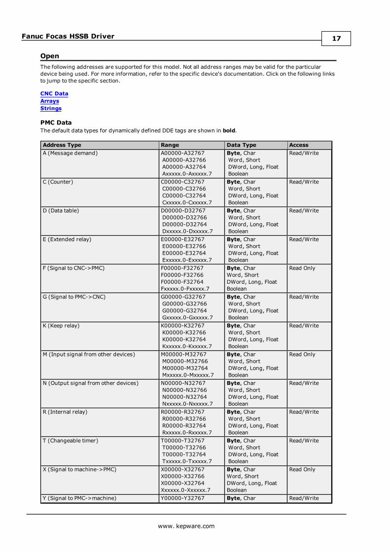
OpenThe following addresses are supported for this model. Not all address ranges may be valid for the particulardevice being used. For more information, refer to the specific device's documentation. Click on the following linksto jump to the specific section.
CNC DataArraysStrings
PMC DataThe default data types for dynamically defined DDE tags are shown in bold.
Address Type Range Data Type AccessA (Message demand) A00000-A32767
A00000-A32766A00000-A32764Axxxxx.0-Axxxxx.7
Byte, CharWord, ShortDWord, Long, FloatBoolean
Read/Write
C (Counter) C00000-C32767C00000-C32766C00000-C32764Cxxxxx.0-Cxxxxx.7
Byte, CharWord, ShortDWord, Long, FloatBoolean
Read/Write
D (Data table) D00000-D32767D00000-D32766D00000-D32764Dxxxxx.0-Dxxxxx.7
Byte, CharWord, ShortDWord, Long, FloatBoolean
Read/Write
E (Extended relay) E00000-E32767E00000-E32766E00000-E32764Exxxxx.0-Exxxxx.7
Byte, CharWord, ShortDWord, Long, FloatBoolean
Read/Write
F (Signal to CNC->PMC) F00000-F32767F00000-F32766F00000-F32764Fxxxxx.0-Fxxxxx.7
Byte, CharWord, ShortDWord, Long, FloatBoolean
Read Only
G (Signal to PMC->CNC) G00000-G32767G00000-G32766G00000-G32764Gxxxxx.0-Gxxxxx.7
Byte, CharWord, ShortDWord, Long, FloatBoolean
Read/Write
K (Keep relay) K00000-K32767K00000-K32766K00000-K32764Kxxxxx.0-Kxxxxx.7
Byte, CharWord, ShortDWord, Long, FloatBoolean
Read/Write
M (Input signal from other devices) M00000-M32767M00000-M32766M00000-M32764Mxxxxx.0-Mxxxxx.7
Byte, CharWord, ShortDWord, Long, FloatBoolean
Read Only
N (Output signal from other devices) N00000-N32767N00000-N32766N00000-N32764Nxxxxx.0-Nxxxxx.7
Byte, CharWord, ShortDWord, Long, FloatBoolean
Read/Write
R (Internal relay) R00000-R32767R00000-R32766R00000-R32764Rxxxxx.0-Rxxxxx.7
Byte, CharWord, ShortDWord, Long, FloatBoolean
Read/Write
T (Changeable timer) T00000-T32767T00000-T32766T00000-T32764Txxxxx.0-Txxxxx.7
Byte, CharWord, ShortDWord, Long, FloatBoolean
Read/Write
X (Signal to machine->PMC) X00000-X32767X00000-X32766X00000-X32764Xxxxxx.0-Xxxxxx.7
Byte, CharWord, ShortDWord, Long, FloatBoolean
Read Only
Y (Signal to PMC->machine) Y00000-Y32767 Byte, Char Read/Write
www. kepware.com
17

Fanuc Focas HSSB Driver
Address Type Range Data Type AccessY00000-Y32766Y00000-Y32764Yxxxxx.0-Yxxxxx.7
Word, ShortDWord, Long, FloatBoolean
Custom Macro Value (common range) #0100-#0999 Float Read/WriteCustom Macro Value (local range) #0001-#0033 Float Read OnlyCustom Macro Value (system range) #1000-#9999 Float Read/Write
CNC DataTool OffsetWorkpiece Zero Offset
ArraysArrays are supported for all PMC addresses, except for Custom Macros in the system range and where Boolean orstring data types are used. Tool Offset data cannot be addressed as an array. The syntax for declaring an array isas follows:
Mxxxxx[cols] with assumed row count of 1.Mxxxxx[rows][cols] where M is the address type and xxxxx is the byte offset of the first element in the array.
Note: For all arrays, the total number of bytes being requested cannot exceed the specified request size.
StringsAll address types can be read and written to as ASCII strings. Each byte of memory will contain one ASCIIcharacter. The length of strings can range from 1 to 120 and is entered in place of the bit number. An additionalcharacter "M" is appended to the address to distinguish string addresses from bit addresses.
ExampleTo address a string of length 100 characters, starting at D00200, enter D00200.100 M.
Note: Use caution when modifying Word, Short, DWord, Long, and Float types. Since all addresses start at abyte offset within the device, it is possible for the memory associated with tags to overlap. For example, wordtags D00000 and D00001 overlap at byte 1. Writing to D00000 will also modify the value held in D00001. It isrecommended that these memory types be used such that each value to be read and written to by the driveroccupy a unique range of memory in the device. For example, users might map 3 Word values to bytes D00000-D00001, D00002-D00003, and D00004-D00005. Tags to access these values would then have addressesD00000, D00002, and D00004 respectively, and a data type of Word.
Tool OffsetCNC DataAddress Type Range Data Type AccessTool Offset TOFS:nn:o
nn = Tool Number (01-64)o = Offset Type(0-9, see note below)
Long, DWord Read/Write
Tool Offset TypesThe tool offset type's meaning depends on the hardware. The following tables summarize the various offsettypes.
Cutter Radius Tool LengthWear 0 2Geometry 1 3
Lathe Series (T series)X-Axis Z-Axis Nose R Imaginary Tool Nose Y-Axis
Wear 0 2 4 6 8Geometry 1 3 5 7 9
Tool Offset Values
www. kepware.com
18
Fanuc Focas HSSB Driver
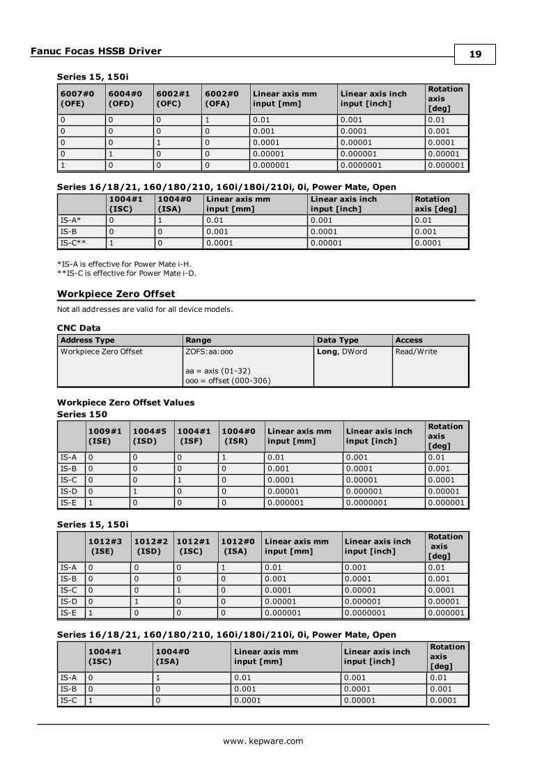
Series 15, 150i
6007#0(OFE)
6004#0(OFD)
6002#1(OFC)
6002#0(OFA)
Linear axis mminput [mm]
Linear axis inchinput [inch]
Rotationaxis[deg]
0 0 0 1 0.01 0.001 0.010 0 0 0 0.001 0.0001 0.0010 0 1 0 0.0001 0.00001 0.00010 1 0 0 0.00001 0.000001 0.000011 0 0 0 0.000001 0.0000001 0.000001
Series 16/18/21, 160/180/210, 160i/180i/210i, 0i, Power Mate, Open1004#1(ISC)
1004#0(ISA)
Linear axis mminput [mm]
Linear axis inchinput [inch]
Rotationaxis [deg]
IS-A* 0 1 0.01 0.001 0.01IS-B 0 0 0.001 0.0001 0.001IS-C** 1 0 0.0001 0.00001 0.0001
*IS-A is effective for Power Mate i-H.**IS-C is effective for Power Mate i-D.
Workpiece Zero OffsetNot all addresses are valid for all device models.
CNC DataAddress Type Range Data Type AccessWorkpiece Zero Offset ZOFS:aa:ooo
aa = axis (01-32)ooo = offset (000-306)
Long, DWord Read/Write
Workpiece Zero Offset ValuesSeries 150
1009#1(ISE)
1004#5(ISD)
1004#1(ISF)
1004#0(ISR)
Linear axis mminput [mm]
Linear axis inchinput [inch]
Rotationaxis[deg]
IS-A 0 0 0 1 0.01 0.001 0.01IS-B 0 0 0 0 0.001 0.0001 0.001IS-C 0 0 1 0 0.0001 0.00001 0.0001IS-D 0 1 0 0 0.00001 0.000001 0.00001IS-E 1 0 0 0 0.000001 0.0000001 0.000001
Series 15, 150i
1012#3(ISE)
1012#2(ISD)
1012#1(ISC)
1012#0(ISA)
Linear axis mminput [mm]
Linear axis inchinput [inch]
Rotationaxis[deg]
IS-A 0 0 0 1 0.01 0.001 0.01IS-B 0 0 0 0 0.001 0.0001 0.001IS-C 0 0 1 0 0.0001 0.00001 0.0001IS-D 0 1 0 0 0.00001 0.000001 0.00001IS-E 1 0 0 0 0.000001 0.0000001 0.000001
Series 16/18/21, 160/180/210, 160i/180i/210i, 0i, Power Mate, Open
1004#1(ISC)
1004#0(ISA)
Linear axis mminput [mm]
Linear axis inchinput [inch]
Rotationaxis[deg]
IS-A 0 1 0.01 0.001 0.01IS-B 0 0 0.001 0.0001 0.001IS-C 1 0 0.0001 0.00001 0.0001
www. kepware.com
19
Fanuc Focas HSSB Driver
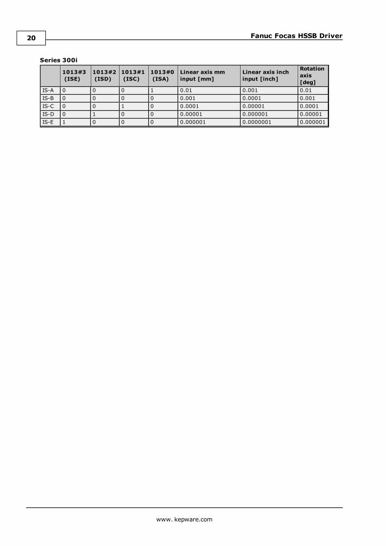
Series 300i
1013#3(ISE)
1013#2(ISD)
1013#1(ISC)
1013#0(ISA)
Linear axis mminput [mm]
Linear axis inchinput [inch]
Rotationaxis[deg]
IS-A 0 0 0 1 0.01 0.001 0.01IS-B 0 0 0 0 0.001 0.0001 0.001IS-C 0 0 1 0 0.0001 0.00001 0.0001IS-D 0 1 0 0 0.00001 0.000001 0.00001IS-E 1 0 0 0 0.000001 0.0000001 0.000001
www. kepware.com
20
Fanuc Focas HSSB Driver
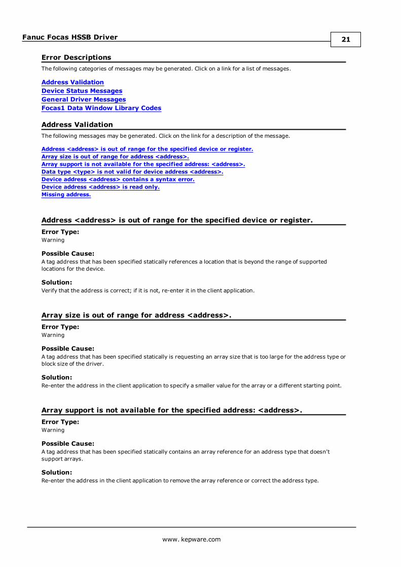
Error DescriptionsThe following categories of messages may be generated. Click on a link for a list of messages.
Address ValidationDevice Status MessagesGeneral Driver MessagesFocas1 Data Window Library Codes
Address ValidationThe following messages may be generated. Click on the link for a description of the message.
Address <address> is out of range for the specified device or register.Array size is out of range for address <address>.Array support is not available for the specified address: <address>.Data type <type> is not valid for device address <address>.Device address <address> contains a syntax error.Device address <address> is read only.Missing address.
Address <address> is out of range for the specified device or register.Error Type:Warning
Possible Cause:A tag address that has been specified statically references a location that is beyond the range of supportedlocations for the device.
Solution:Verify that the address is correct; if it is not, re-enter it in the client application.
Array size is out of range for address <address>.Error Type:Warning
Possible Cause:A tag address that has been specified statically is requesting an array size that is too large for the address type orblock size of the driver.
Solution:Re-enter the address in the client application to specify a smaller value for the array or a different starting point.
Array support is not available for the specified address: <address>.Error Type:Warning
Possible Cause:A tag address that has been specified statically contains an array reference for an address type that doesn'tsupport arrays.
Solution:Re-enter the address in the client application to remove the array reference or correct the address type.
www. kepware.com
21
Fanuc Focas HSSB Driver
Data Type <type> is not valid for device address <address>.Error Type:Warning
Possible Cause:A tag address that has been specified statically has been assigned an invalid data type.
Solution:Modify the requested data type in the client application.
Device address <address> contains a syntax error.Error Type:Warning
Possible Cause:A tag address that has been specified statically contains one or more invalid characters.
Solution:Re-enter the address in the client application.
Device address <address> is read only.Error Type:Warning
Possible Cause:A tag address that has been specified statically has a requested access mode that is not compatible with what thedevice supports for that address.
Solution:Change the access mode in the client application.
Missing address.Error Type:Warning
Possible Cause:A tag address that has been specified statically has no length.
Solution:Re-enter the address in the client application.
Device Status Messages.The following messages may be generated. Click on the link for a description of the message.
Device <device name> is not respondingUnable to write to <address> on device <device name>
Device <device name> is not responding.Error Type:Serious
Possible Cause:
www. kepware.com
22
Fanuc Focas HSSB Driver
1. The connection between the device and the host PC is broken.
2. The IP address assigned to the device is incorrect.
3. The response from the device took longer to receive than the amount of time specified in the "RequestTimeout" device setting.
Solution:
1. Verify the cabling between the PC and the PLC device.
2. Verify that the IP address given to the named device matches that of the actual device.
3. Increase the Request Timeout setting so that the entire response can be handled.
Unable to write to <address> on device <device name>.Error Type:Serious
Possible Cause:
1. The connection between the device and the host PC is broken.
2. The named device may have been assigned an incorrect IP address.
Solution:
1. Verify the cabling between the PC and the PLC device.
2. Verify that the IP address given to the named device matches that of the actual device.
General Driver MessagesThe following messages may be generated. Click on the link for a description of the message.
Could not acquire library handle for device <channel.device>. FWLIB error: <code>.Could not set request timeout for device <channel.device>. FWLIB error: <code>.Could not read one or more vacant macros in range starting at <address> on device <device>.Device ID <node> is too large for device <channel.device>. The maximum allowed is <max. node>.Failed to read maximum Node ID for device <channel.device>. FWLIB error: <code>.Read error occurred for address starting at <address> on device <channel.device>. FWLIB error:<code>.Unable to start the Fanuc Focas Data Window Library services.Write error occurred for address <address> on device <channel.device>. FWLIB error: <code>.
Could not acquire library handle for device <channel.device>. FWLIB error:<code>.Error Type:Warning
Possible Cause:
1. Call to Focas1 Data Window Library to connect to device failed.
2. Invalid device IP or port number.
3. The device may not be running.
4. The device may be busy processing other requests.
5. There may be a cabling problem.
Solution:
www. kepware.com
23

Fanuc Focas HSSB Driver
The error code provided by the library should help diagnose the problem. If the problem is transient, the drivershould be able to connect on a subsequent retry.
See Also:Focas1 Data Window Library Error Codes
Could not read one or more vacant macros in range starting at <address> ondevice <device>.Error Type:Warning
Possible Cause:The macro number is not configured in the device.
Solution:Check the tag address and device configuration.
Could not set request timeout for device <channel.device>. FWLIB error:<code>.Error Type:Warning
Possible Cause:
1. Call to Focas1 Data Window Library to set request timeout failed.
2. Invalid timeout.
3. The device may be busy processing other requests.
4. There may be a cabling problem.
Solution:The error code provided by the library should help diagnose the problem. If the problem is transient, the drivershould be able to set the timeout on a subsequent retry.
See Also:Focas1 Data Window Library Error Codes
Device ID <node> is too large for device <channel.device>. The maximumallowed is <max. node>.Error Type:Serious
Possible Cause:The node number configured as the Device ID is greater than the maximum node supported by the controller.
Solution:Set the Device ID to a compatible node number.
Failed to read maximum Node ID for device <channel.device>. FWLIB error:<code>.Error Type:Serious
Possible Cause:
www. kepware.com
24
Fanuc Focas HSSB Driver
1. There is something wrong with the connection.
2. An incorrect version of the Focas library is installed.
3. The HSSB interface card and/or the drivers that are required for execution are not installed.
Solution:
1. Check the connection between the device and the host computer.
2. Ensure that "Focas1 for HSSB" or "Focas2 (Combined Ethernet and HSSB)" library software is installed onthe host computer.
3. Install an HSSB interface card in the host computer, and use the appropriate fiber optic cable to connect itto the controller.
See Also:Focas1 Data Window Library Error Codes
Read error occurred for address starting at <address> on device<channel.device>. FWLIB error: <code>.Error Type:Warning
Possible Cause:
1. Call to Focas1 Data Window Library to read data failed.
2. Invalid PMC type.
3. Invalid addresses.
4. Invalid request size.
5. The device may be busy processing other requests.
6. There may be a cabling problem.
Solution:The error code provided by the library should help diagnose the problem. If the problem is transient, the drivershould be able to read the data on a subsequent retry.
See Also:Focas1 Data Window Library Error Codes
Unable to start the Fanuc Focas Data Window Library services.Error Type:Fatal
Possible Cause:The driver was unable to load the Fanuc Focas1 Data Window Library.
Solution:Make sure the library is installed on the computer. Contact the GE distributor for this software.
Write error occurred for address <address> on device <channel.device>.FWLIB error: <code>.Error Type:Warning
Possible Cause:
www. kepware.com
25
Fanuc Focas HSSB Driver
1. Call to Focas1 Data Window Library to write data failed.
2. Invalid PMC type.
3. Invalid address.
4. Invalid request size.
5. The device may be busy processing other requests.
6. There may be a cabling problem.
Solution:The error code provided by the library should help diagnose the problem. If the problem is transient, the drivershould be able to write the data on a subsequent retry.
See Also:Focas1 Data Window Library Error Codes
www. kepware.com
26
Fanuc Focas HSSB Driver
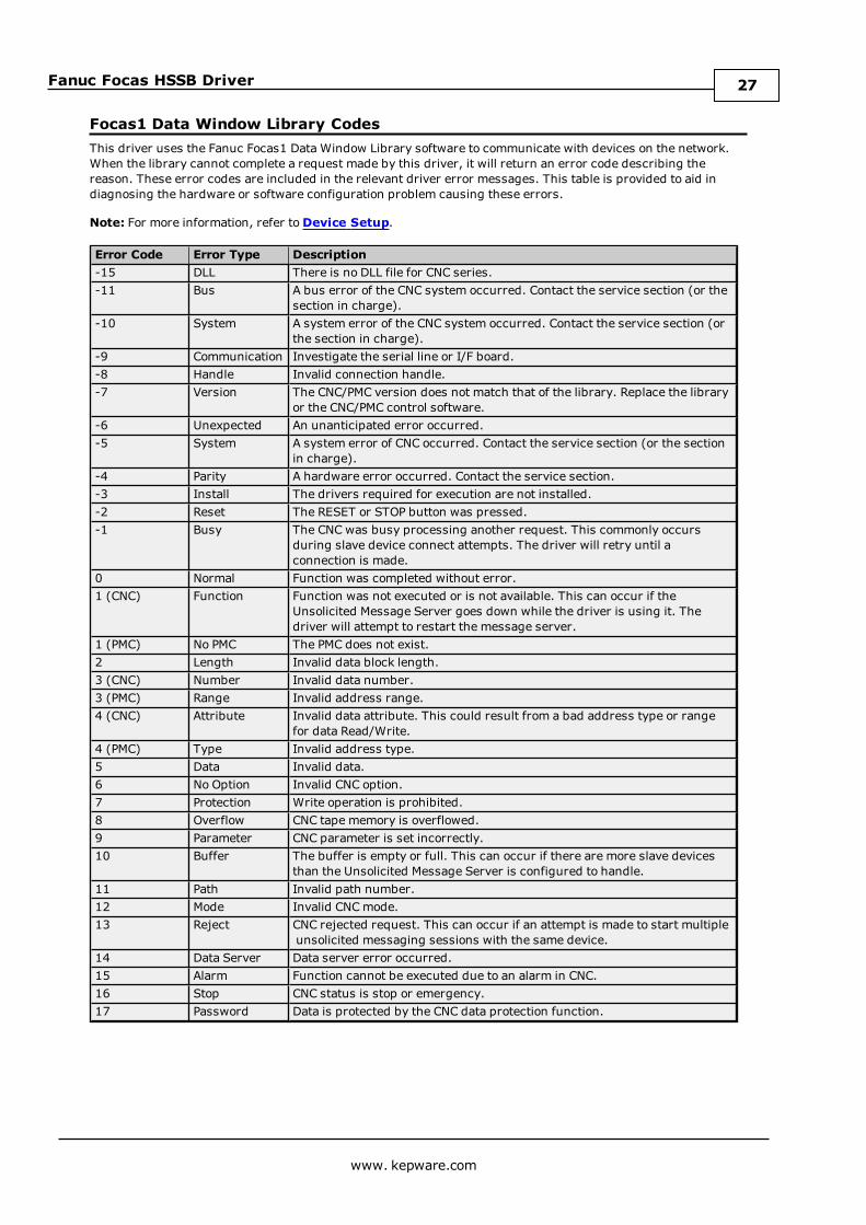
Focas1 Data Window Library CodesThis driver uses the Fanuc Focas1 Data Window Library software to communicate with devices on the network.When the library cannot complete a request made by this driver, it will return an error code describing thereason. These error codes are included in the relevant driver error messages. This table is provided to aid indiagnosing the hardware or software configuration problem causing these errors.
Note: For more information, refer toDevice Setup.
Error Code Error Type Description-15 DLL There is no DLL file for CNC series.-11 Bus A bus error of the CNC system occurred. Contact the service section (or the
section in charge).-10 System A system error of the CNC system occurred. Contact the service section (or
the section in charge).-9 Communication Investigate the serial line or I/F board.-8 Handle Invalid connection handle.-7 Version The CNC/PMC version does not match that of the library. Replace the library
or the CNC/PMC control software.-6 Unexpected An unanticipated error occurred.-5 System A system error of CNC occurred. Contact the service section (or the section
in charge).-4 Parity A hardware error occurred. Contact the service section.-3 Install The drivers required for execution are not installed.-2 Reset The RESET or STOP button was pressed.-1 Busy The CNC was busy processing another request. This commonly occurs
during slave device connect attempts. The driver will retry until aconnection is made.
0 Normal Function was completed without error.1 (CNC) Function Function was not executed or is not available. This can occur if the
Unsolicited Message Server goes down while the driver is using it. Thedriver will attempt to restart the message server.
1 (PMC) No PMC The PMC does not exist.2 Length Invalid data block length.3 (CNC) Number Invalid data number.3 (PMC) Range Invalid address range.4 (CNC) Attribute Invalid data attribute. This could result from a bad address type or range
for data Read/Write.4 (PMC) Type Invalid address type.5 Data Invalid data.6 No Option Invalid CNC option.7 Protection Write operation is prohibited.8 Overflow CNC tape memory is overflowed.9 Parameter CNC parameter is set incorrectly.10 Buffer The buffer is empty or full. This can occur if there are more slave devices
than the Unsolicited Message Server is configured to handle.11 Path Invalid path number.12 Mode Invalid CNCmode.13 Reject CNC rejected request. This can occur if an attempt is made to start multiple
unsolicited messaging sessions with the same device.14 Data Server Data server error occurred.15 Alarm Function cannot be executed due to an alarm in CNC.16 Stop CNC status is stop or emergency.17 Password Data is protected by the CNC data protection function.
www. kepware.com
27
Fanuc Focas HSSB Driver
Index
A
Address <address> is out of range for the specified device or register. 21
Address Descriptions 9
Address Validation 21
Array size is out of range for address <address>. 21
Array support is not available for the specified address:<address>. 21
B
Boolean 8
C
Communications Parameters 6
Could not acquire library handle for device <channel.device>. FWLIB error <code>. 23
Could not read one or more vacant macros in range starting at <address> on device <device>. 24
Could not set request timeout for device <channel.device>. FWLIB error <code>. 24
D
Data Type <type> is not valid for device address <address>. 22
Data Types Description 8
Device <device name> is not responding. 22
Device address <address> contains a syntax error. 22
Device address <address> is read only. 22
Device ID 5
Device ID <node> is too large for device <channel.device>. The maximum allowed is <max node>. 24
Device Setup 5
Device Status Messages. 22
Driver Error Messages 23
DWord 8
E
Error Descriptions 21
External Dependencies 4
www. kepware.com
28
Fanuc Focas HSSB Driver
F
Failed to read maximum Node ID for device <channel.device>. FWLIB error: <code>. 24
Float 8
Focas1 Data Window Library Error Codes 27
I
Install Focas Library 4
L
Long 8
M
Missing address. 22
N
Network 5
O
Open 17
Optimizing Fanuc Focas HSSB Communications 7
Overview 4
P
Power Mate i 15
R
Read error occurred for address starting at <address> on device <channel.device>. FWLIB error<code>. 25
S
Series 15i 9
Series 16i 10
www. kepware.com
29

Fanuc Focas HSSB Driver
Series 18i 12
Series 21i 13
Short 8
T
Tool Offset Tags 18
U
Unable to start the Fanuc Focas Data Window Library services. 25
Unable to write tag <address> on device <device name>. 23
W
Word 8
Workpiece Zero Offset Tags 19
Write error occurred for address <address> on device <channel.device>. FWLIB error <code>. 25
www. kepware.com
30