Embed Size (px)
Citation preview

FANUC I/O Unit-MODEL A
CONNECTION AND MAINTENANCE MANUAL
B-61813E/04
http://www.cncspares.com/

• No part of this manual may be reproduced in any form. • All specifications and designs are subject to change without notice. In this manual we have tried as much as possible to describe all the various matters. However, we cannot describe all the matters which must not be done, or which cannot be done, because there are so many possibilities. Therefore, matters which are not especially described as possible in this manual should be regarded as ”impossible”. This manual contains the program names or device names of other companies, some of which are registered trademarks of respective owners. However, these names are not followed by or in the main body.
http://www.cncspares.com/
B-61813E/04 DEFINITION OF WARNING, CAUTION, AND NOTE
s-1
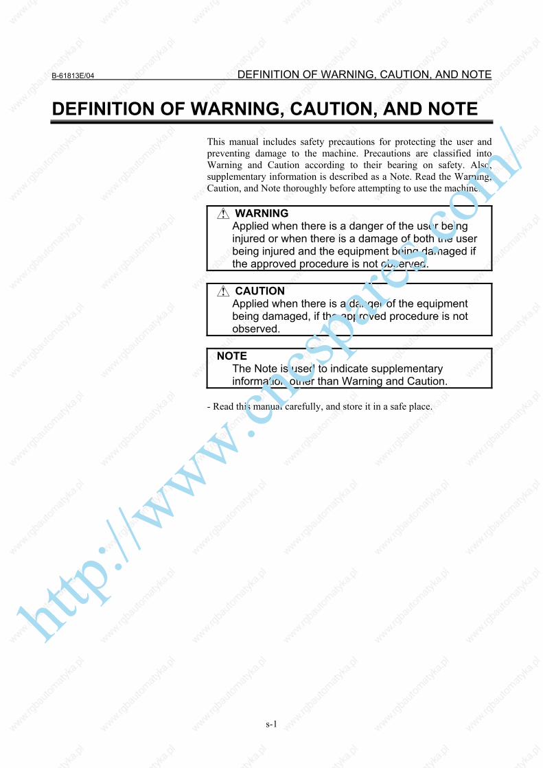
DEFINITION OF WARNING, CAUTION, AND NOTE This manual includes safety precautions for protecting the user and preventing damage to the machine. Precautions are classified into Warning and Caution according to their bearing on safety. Also, supplementary information is described as a Note. Read the Warning, Caution, and Note thoroughly before attempting to use the machine.
WARNING Applied when there is a danger of the user being
injured or when there is a damage of both the user being injured and the equipment being damaged if the approved procedure is not observed.
CAUTION
Applied when there is a danger of the equipment being damaged, if the approved procedure is not observed.
NOTE The Note is used to indicate supplementary
information other than Warning and Caution. - Read this manual carefully, and store it in a safe place.
http://www.cncspares.com/

http://www.cncspares.com/

B-61813E/04 PREFACE
p-1
PREFACE
Applicable models This manual describe the following products:
Name of products Abbreviation FANUC I/O Unit-MODEL A I/O Unit-A
Applicable CNCs
Name of products Abbreviation FANUC Power Mate Power Mate FANUC Series 0 (MODEL C) Series 0-C FANUC Series 15 Series 15 FANUC Series 16 Series 16 FANUC Series 18 Series 18 FANUC Series 20 Series 20 FANUC Series 21 Series 21 FANUC SYSTEM F-MODEL D Mate F-D Mate FANUC Power Mate i Power Mate i FANUC Series 0i Series 0i FANUC Series 15i Series 15i FANUC Series 16i Series 16i FANUC Series 18i Series 18i FANUC Series 20i Series 20i FANUC Series 21i Series 21i FANUC Series 30i Series 30i FANUC Series 31i Series 31i FANUC Series 32i Series 32i
Other related models
Name of products Abbreviation FANUC I/O Unit-MODEL B I/O Unit-B
Abbreviations of manufacturer names used herein
This manual uses the following abbreviations for manufacturers of products such as connectors.
Manufacturer name Abbreviation Daito Communication Apparatus Co., Ltd. Daito Fujitsu Limited Fujitsu HIROSE ELECTRIC CO., LTD. HIROSE ELECTRIC HONDA TSUSHIN KOGYO CO., LTD. HONDA TSUSHIN Molex Incorporated Molex Nihon Weidmüller Co., Ltd. Weidmüller SORIAU JAPAN SORIAU JAPAN Tyco Electronics AMP K.K. Tyco Electronics
http://www.cncspares.com/

http://www.cncspares.com/

B-61813E/04 TABLE OF CONTENTS
c-1
TABLE OF CONTENTS
DEFINITION OF WARNING, CAUTION, AND NOTE .................................s-1 PREFACE....................................................................................................p-1
I. CONNECTION
1 FANUC I/O Link ......................................................................................3 1.1 CONFIGURATION......................................................................................... 4 1.2 ALLOCATION OF I/O POINTS...................................................................... 5
2 I/O Unit CONFIGURATION.....................................................................7 3 INSTALLATION ......................................................................................8
3.1 ENVIRONMENT FOR INSTALLATION ......................................................... 9 3.1.1 Environmental Conditions outside the Cabinet ........................................................9
3.2 DESIGNING CONDITION FOR A CABINET ............................................... 10 3.3 OUTER DIMENSION OF I/O Unit................................................................ 11 3.4 MOUNTING AND DISMOUNTING MODULES............................................ 15
4 CONNECTION.......................................................................................16 4.1 GENERAL CONNECTION DIAGRAM......................................................... 17 4.2 CONNECTING INPUT POWER SOURCE .................................................. 18 4.3 GROUNDING .............................................................................................. 19 4.4 REQUIRED CURRENT ............................................................................... 20 4.5 INTERFACE MODULE (AIF01A, AIF01A2, AIF01B) ................................... 21 4.6 INTERFACE MODULE (AIF02C) CONNECTION........................................ 24
4.6.1 Overview ................................................................................................................24 4.6.2 Connection .............................................................................................................25 4.6.3 Setting with the DIP Switch ...................................................................................27
4.7 CONNECTING WITH I/O MODULES.......................................................... 28
5 DIGITAL INPUT/OUTPUT MODULES ..................................................30 5.1 LIST OF MODULES .................................................................................... 31 5.2 CORRESPONDENCE BETWEEN I/O SIGNALS AND ADDRESSES IN A
MODULE ..................................................................................................... 34 5.2.1 Module with 16/32 Digital Inputs (DI) ..................................................................34 5.2.2 Module with 5/8/12/16/32 Digital Outputs (DO)...................................................34 5.2.3 AIO40A Module (Hybrid Module with 24 Input and 16 Output Points)...............35
5.3 SPECIFICATION FOR EACH MODULE ..................................................... 36
http://www.cncspares.com/

TABLE OF CONTENTS B-61813E/04
c-2
5.4 DETAILS OF I/O Unit CONNECTORS (HONDA TSUSHIN/HIROSE ELECTRIC) AND TERMINAL BLOCK (WEIDMÜLLER).............................. 74 5.4.1 Modules Using the MR-50RMA Connector Manufactured by Honda Tsushin.....75 5.4.2 Modules Using the HIF3BB-50PA-2.54DS Connector Manufactured by
Hirose Electric........................................................................................................77 5.4.3 Modules Using the HIF4-40P-3.18DS Connector Manufactured by
Hirose Electric........................................................................................................79 5.4.4 Modules Using the Terminal Block BL3.5/24/90F Manufactured by
Weidmüller.............................................................................................................80
6 ANALOG INPUT MODULE...................................................................81 6.1 12-BIT ANALOG INPUT MODULE (AAD04A) ............................................. 82
6.1.1 Specifications .........................................................................................................82 6.1.2 Correspondence between Input Signals and Addresses in a Module .....................83 6.1.3 Connecting with Analog Input Module..................................................................85
6.2 16-BIT ANALOG INPUT MODULE (AAD04B) ............................................. 86 6.2.1 Specifications .........................................................................................................86 6.2.2 Correspondence between Input Signals and Addresses in a Module .....................87 6.2.3 Connecting with Analog Input Module..................................................................89
7 ANALOG OUTPUT MODULE...............................................................90 7.1 12-BIT ANALOG OUTPUT MODULE (ADA02A) ......................................... 91
7.1.1 Specification...........................................................................................................91 7.1.2 Correspondence between Output Signals and Addresses in a Module ..................92 7.1.3 Connection to Analog Output Module ...................................................................93
7.2 14-BIT ANALOG OUTPUT MODULE (ADA02B) ......................................... 94 7.2.1 Specification...........................................................................................................94 7.2.2 Correspondence between Output Signals and Addresses in the Module ...............95 7.2.3 Connection between the Analog Output Module and Load ...................................96
8 HIGH-SPEED COUNTER MODULE .....................................................97 8.1 OUTLINE OF HIGH-SPEED COUNTER MODULE..................................... 98 8.2 SPECIFICATIONS OF HIGH-SPEED COUNTER MODULE..................... 100
8.2.1 Pulse Counter .......................................................................................................100 8.2.2 Comparison Function ...........................................................................................100 8.2.3 Pulse Interface ......................................................................................................102 8.2.4 External Contact Input..........................................................................................105 8.2.5 External Contact Output.......................................................................................105 8.2.6 Marker Processing................................................................................................106
http://www.cncspares.com/

B-61813E/04 TABLE OF CONTENTS
c-3
8.2.7 LED indicators .....................................................................................................107 8.3 PMC INTERFACE ..................................................................................... 109
8.3.1 Mode A.................................................................................................................109 8.3.2 Mode B.................................................................................................................111 8.3.3 Details of PMC Interface Signals .........................................................................114
8.4 TOTAL CONNECTION OF HIGH-SPEED COUNTER MODULE.............. 117 8.4.1 Connection Diagram.............................................................................................117 8.4.2 Connector Signal List ...........................................................................................117
8.4.2.1 C49 signal (for mode A) .................................................................................. 118 8.4.2.2 C49 signal (for mode B) .................................................................................. 118
8.5 CONNECTION WITH PULSE GENERATOR ............................................ 119 8.5.1 Use of Phase A and B Pulses................................................................................119 8.5.2 Use of Positive/Negative Pulses...........................................................................120
8.6 CONNECTION WITH MACHINE (POWER MAGNETICS CABINET) ....... 121 8.6.1 Use in Mode A .....................................................................................................121 8.6.2 Use in Mode B......................................................................................................122
8.7 I/O SIGNALS CONVENTIONS .................................................................. 123 8.7.1 Solid State Relay Output Signals (OUT0 to OUT7) ............................................123 8.7.2 DC Input Signals (ME and CSP)..........................................................................124 8.7.3 +5-V Output from JA9 Connector........................................................................124
8.8 SUPPLEMENT .......................................................................................... 125 8.8.1 Configuration of Mode A.....................................................................................125 8.8.2 Counter Presetting and Counting .........................................................................126 8.8.3 Setting Data ..........................................................................................................129 8.8.4 Reading Data ........................................................................................................130
8.9 EXAMPLE OF STARTING UP ACT01A .................................................... 131 8.9.1 Mode A Startup Flowchart ...................................................................................131 8.9.2 Example of Mode A Ladder .................................................................................132 8.9.3 Mode B Startup Flowchart ...................................................................................136 8.9.4 Example of Mode B Ladder .................................................................................137
9 TEMPERATURE INPUT MODULE .....................................................144 9.1 OVERVIEW ............................................................................................... 145 9.2 TEMPERATURE INPUT MODULE SPECIFICATION ............................... 146 9.3 PMC INTERFACE ..................................................................................... 147
9.3.1 PMC I/O Area ......................................................................................................147 9.3.2 Measurement Mode..............................................................................................148 9.3.3 Details of Output Signals (PMC → Temperature Module)..................................148
http://www.cncspares.com/
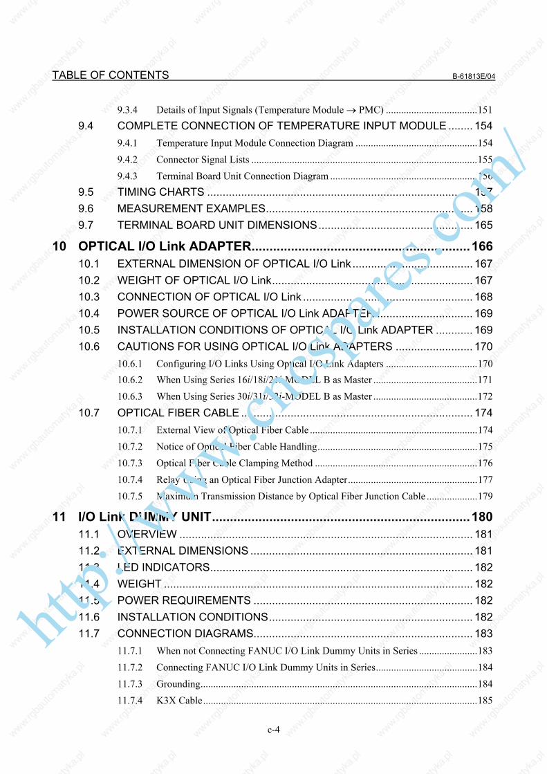
TABLE OF CONTENTS B-61813E/04
c-4
9.3.4 Details of Input Signals (Temperature Module → PMC) ....................................151 9.4 COMPLETE CONNECTION OF TEMPERATURE INPUT MODULE ........ 154
9.4.1 Temperature Input Module Connection Diagram ................................................154 9.4.2 Connector Signal Lists .........................................................................................155 9.4.3 Terminal Board Unit Connection Diagram ..........................................................156
9.5 TIMING CHARTS ...................................................................................... 157 9.6 MEASUREMENT EXAMPLES................................................................... 158 9.7 TERMINAL BOARD UNIT DIMENSIONS.................................................. 165
10 OPTICAL I/O Link ADAPTER.............................................................166 10.1 EXTERNAL DIMENSION OF OPTICAL I/O Link ....................................... 167 10.2 WEIGHT OF OPTICAL I/O Link................................................................. 167 10.3 CONNECTION OF OPTICAL I/O Link ....................................................... 168 10.4 POWER SOURCE OF OPTICAL I/O Link ADAPTER ............................... 169 10.5 INSTALLATION CONDITIONS OF OPTICAL I/O Link ADAPTER ............ 169 10.6 CAUTIONS FOR USING OPTICAL I/O Link ADAPTERS ......................... 170
10.6.1 Configuring I/O Links Using Optical I/O Link Adapters ....................................170 10.6.2 When Using Series 16i/18i/21i-MODEL B as Master .........................................171 10.6.3 When Using Series 30i/31i/32i-MODEL B as Master .........................................172
10.7 OPTICAL FIBER CABLE ........................................................................... 174 10.7.1 External View of Optical Fiber Cable ..................................................................174 10.7.2 Notice of Optical Fiber Cable Handling...............................................................175 10.7.3 Optical Fiber Cable Clamping Method ................................................................176 10.7.4 Relay Using an Optical Fiber Junction Adapter...................................................177 10.7.5 Maximum Transmission Distance by Optical Fiber Junction Cable ....................179
11 I/O Link DUMMY UNIT........................................................................180 11.1 OVERVIEW ............................................................................................... 181 11.2 EXTERNAL DIMENSIONS ........................................................................ 181 11.3 LED INDICATORS..................................................................................... 182 11.4 WEIGHT .................................................................................................... 182 11.5 POWER REQUIREMENTS ....................................................................... 182 11.6 INSTALLATION CONDITIONS.................................................................. 182 11.7 CONNECTION DIAGRAMS....................................................................... 183
11.7.1 When not Connecting FANUC I/O Link Dummy Units in Series .......................183 11.7.2 Connecting FANUC I/O Link Dummy Units in Series........................................184 11.7.3 Grounding.............................................................................................................184 11.7.4 K3X Cable............................................................................................................185
http://www.cncspares.com/

B-61813E/04 TABLE OF CONTENTS
c-5
12 TWO-CHANNEL I/O Link CONNECTOR ADAPTER .........................186 12.1 OVERVIEW ............................................................................................... 187 12.2 CONNECTION FOR USE OF TWO FANUC I/O Link CHANNELS ........... 187 12.3 CONNECTING THE CNC WITH TWO-CHANNEL I/O Link CONNECTOR
ADAPTER.................................................................................................. 188 12.4 CABLING................................................................................................... 189 12.5 CONNECTING TWO-CHANNEL I/O Link CONNECTOR ADAPTER TO
I/O Units FOR THE FANUC I/O Link ......................................................... 189 12.6 CABLE LENGTH ....................................................................................... 190 12.7 INSTALLING TWO-CHANNEL I/O Link CONNECTOR ADAPTER ........... 190 12.8 OUTSIDE DIMENSIONS OF TWO-CHANNEL I/O Link CONNECTOR
ADAPTER.................................................................................................. 191 12.9 MOUNTING TWO-CHANNEL I/O Link CONNECTOR ADAPTER ............ 192
13 THREE-CHANNEL I/O Link CONNECTOR ADAPTER .....................193 13.1 OVERVIEW ............................................................................................... 194 13.2 CONNECTION FOR USE OF FOUR FANUC I/O Link CHANNELS.......... 194 13.3 CONNECTING THE CNC WITH THREE-CHANNEL I/O Link
CONNECTOR ADAPTER.......................................................................... 195 13.4 CABLING................................................................................................... 195 13.5 ALLOCATING THREE-CHANNEL I/O Link CONNECTOR ADAPTER
SIGNALS ................................................................................................... 196 13.6 CONNECTING THREE-CHANNEL I/O Link CONNECTOR ADAPTER
SIGNAL TO EACH CHANNEL................................................................... 197 13.7 CONNECTING THREE-CHANNEL I/O Link CONNECTOR ADAPTER
TO TWO-CHANNEL I/O Link CONNECTOR ADAPTER........................... 199 13.8 CONNECTING THREE-CHANNEL I/O Link CONNECTOR ADAPTER
TO I/O Units FOR THE FANUC I/O Link ................................................... 200 13.9 CABLE LENGTH ....................................................................................... 200 13.10 INSTALLING THREE-CHANNEL I/O Link CONNECTOR ADAPTER ....... 200 13.11 OUTSIDE DIMENSIONS OF THREE-CHANNEL I/O Link CONNECTOR
ADAPTER.................................................................................................. 201 13.12 MOUNTING THREE-CHANNEL I/O Link CONNECTOR ADAPTER......... 202
14 SAFETY FOR USING AC....................................................................203 14.1 ENVIRONMENT FOR INSTALLATION ..................................................... 204
14.1.1 Installation Category (Overvoltage Category) .....................................................204 14.1.2 Pollution Degree...................................................................................................204
http://www.cncspares.com/

TABLE OF CONTENTS B-61813E/04
c-6
II. MAINTENANCE
1 OVERVIEW .........................................................................................207 1.1 SYSTEM CONFIGURATION..................................................................... 208 1.2 I/O Unit-A CONFIGURATION.................................................................... 209 1.3 BLOCK DIAGRAM..................................................................................... 210 1.4 I/O Unit-MODEL A CONFORMING TO UL/C-UL ...................................... 211 1.5 LIST OF UNITS ......................................................................................... 212
1.5.1 Units Conforming to UL/C-UL Standard: Ordering Information A03B-0819-Jxxx ..................................................................................................212
1.5.2 Other Units (not Conforming to UL/C-UL) .........................................................214 1.5.3 Early Units (Units not Conforming to UL/C-UL: Ordering Information
A03B-0807-Jxxx).................................................................................................214
2 INDICATION........................................................................................216 2.1 INTERFACE MODULE (AIF01A, AIF01A2) LED INDICATORS................ 217 2.2 INTERFACE MODULE (AIF01B) LED INDICATORS................................ 220 2.3 INTERFACE MODULE (AIF02C) LED INDICATORS................................ 221
2.3.1 PWR Indicator......................................................................................................221 2.3.2 LNK Indicators.....................................................................................................221 2.3.3 ER Indicators........................................................................................................221 2.3.4 LED Indicators .....................................................................................................221 2.3.5 M/S Indicator........................................................................................................222 2.3.6 No. Indicators .......................................................................................................223
2.4 LED INDICATORS ON THE INPUT/OUTPUT MODULES (HAVING 16 OR FEWER INPUT/OUTPUT POINTS) .................................................... 223
3 FUSES.................................................................................................224 4 REMOVING PC BOARDS...................................................................225
4.1 HOW TO REMOVE TERMINAL BOARD-TYPE I/O MODULE PC BOARDS ................................................................................................... 226
4.2 HOW TO REMOVE INTERFACE AND CONNECTOR-TYPE I/O MODULE PC BOARDS ............................................................................. 228 http://www.cncspares.com/

I. CONNECTION
http://www.cncspares.com/

http://www.cncspares.com/

B-61813E/04 CONNECTION 1.FANUC I/O Link
- 3 -
1 FANUC I/O Link I/O Link is a serial interface with a purpose to transfer I/O signals (bit data) between CNC, cell controller, the I/O Unit-MODEL A, the Power Mate and so on at high-speed.
http://www.cncspares.com/

1.FANUC I/O Link CONNECTION B-61813E/04
- 4 -
1.1 CONFIGURATION
CNC I/O Unit-A I/O Unit-A
Power Mate
Group #0
Group
#1
Operator’s panel connection unit
Power Mate
Group #2
Series
0-C
Group #3
Operator’s panel connection unit
Group #15
(1) The FANUC I/O Link is made up of one master and a number of
slaves. Master: Series0-C, Series15/16/18/20/21,
Series15i/16i/18i/20i/21i/30i/31i/32i/0i, Power Mate-D/H, Power Mate i-D/H, F-D Mate
Slave: I/O Unit-A, I/O Unit-B, Operator's panel connection unit, Connector panel I/O module, Power Mate, Series0-C, Servo unit β series (I/O Link option), and so on
(2) Up to 16 groups of slaves can be connected with a single I/O Link. Number of slaves per one group is as follows. I/O Unit-A..............................................Up to 2 units (i.e.2 bases) I/O Unit-B................................................................Up to 30 units
(Basic unit, basic and extension units). Operator's panel I/O module ................................................ 1 unit
(1 basic module and extension modules (up to three) Operator's panel connection unit, connector panel I/O module,
Power Mate, Series0-C, Servo unit β series (I/O Link option) .............................................................................. 1 unit
(3) Any slave can be connected with any group. However, different types of slaves cannot be connected with a single group.
Slave
: : :: : : : : :
http://www.cncspares.com/

B-61813E/04 CONNECTION 1.FANUC I/O Link
- 5 -
1.2 ALLOCATION OF I/O POINTS I/O Link has 1024 input points per 1 channel and 1024 output points per 1 channel as viewed from the master. I/O data is periodically transferred between the master and slaves by allotting these I/O points to each slave.
Each slave can occupy as many I/O points as determined for it. For the I/O Link, the total number of I/O points occupied by all slaves per channel must meet: Number of input points ≤ 1024 Number of output points ≤ 1024 Number of actual I/O points may differ from that of the occupied ones. How to determine the number of I/O points to be allotted to each slave and restrictions for allocation are shown in the followings. (For the allocation method for I/O points, refer to the PMC PROGRAMMING MANUAL.) (1) Sum the numbers of the I/O points for all slaves connected with a
single I/O Link. The sum must satisfy the following restriction : Number of input points ≤ 1024 (per one I/O Link) Number of output points ≤ 1024 (per one I/O Link)
(2) Number of the occupied I/O points per one group must satisfy the following restriction : Number of input points ≤ 256 (per one group) Number of output points ≤ 256 (per one group)
(3) Determine the number of I/O points for the I/O Unit-A using the following.
[Output points] Sum of the actual output Occupied output points in a group points
0 to 32 ⇒ 32 points 40 to 64 ⇒ 64 points 72 to 128 ⇒ 128 points 136 to 256 ⇒ 256 points
NOTE Count AOA05E as 8 points AOA12F as 16 points.
http://www.cncspares.com/

1.FANUC I/O Link CONNECTION B-61813E/04
- 6 -
[Input points] Sum of the actual output Occupied output points in a group points
0 to 32 ⇒ 32 points 40 to 64 ⇒ 64 points 72 to 128 ⇒ 128 points 136 to 256 ⇒ 256 points
However, as result of the calculation above, when the number of input points is not larger than that of the output points in a single group, the number of input points is assumed to be equal to that of the output points.
Example 1 : When the following modules are used in the group
No. 0. AOD32C 3 AID32A 5 AOA12F 2 AIA16G 3 [Output points] 32 × 3 + 16 × 2 = 128 ⇒ 128 points [Input points] 32 × 5 + 16 × 3 = 208 ⇒ 256 points
Example 2: When the following modules are used in the group No.2 AOD16C 7 AID16C 4 AOA05E 9 AIA16G 3 [Output points] 16 ×7 + 8 ×9 = 184 ⇒ 256 points [Input points] 16 ×4 + 16×3 = 112 ⇒ 128 points In this case, as the number of input points is not larger than that of the output points, the number of input points is assumed to be equal to that of the output points, in other words, 256 points.
http://www.cncspares.com/

B-61813E/04 CONNECTION 2.I/O Unit CONFIGURATION
- 7 -
2 I/O Unit CONFIGURATION 5-slot horizontal base unit (ABU05A) 10-slot horizontal base unit (ABU10A) 5-slot vertical base unit (ABU05B)
10-slot vertical base unit (ABU10B)
NOTE I/F : Interface module (AIF01A, AIF01A2,
AIF01B, or AIF02C) 1 to 10 : I/O modules
http://www.cncspares.com/

3.INSTALLATION CONNECTION B-61813E/04
- 8 -
3 INSTALLATION
http://www.cncspares.com/

B-61813E/04 CONNECTION 3.INSTALLATION
- 9 -
3.1 ENVIRONMENT FOR INSTALLATION
3.1.1 Environmental Conditions outside the Cabinet The peripheral units and the control unit have been designed on the assumption that they are housed in closed cabinets. In this manual "cabinet" refers to the following: • Cabinet manufactured by the machine tool builder for housing the
control unit or peripheral units; • Operation pendant, manufactured by the machine tool builder, for
housing the LCD/MDI unit or operator's panel. • Equivalent to the above. The environmental conditions when installing these cabinets shall conform to the following table. Section 3.2 describes the installation and design conditions of a cabinet satisfying these conditions.
Operating 0°C to 45°C Storage, Transport -20°C to 60°C
Ambient temperature of the cabinet Temperature change 0.3°C/minute or less
Normal 75%RH or less, no condensation Humidity Short period
(less than 1 month) 95%RH or less, no condensation
Operating 0.5G or less Vibration Non-operating 1.0G or less Operating Up to 1000 m (Note) Meters above
sea level Non-operating Up to 12000 m
Environment
Normal machine shop environment (The environment must be considered if the cabinets are in a location where the density of dust, coolant, organic solvent, and/or corrosive gas is relatively high.)
NOTE If the CNC is installed 1000 m or higher above sea level,
the allowable upper ambient temperature of the CNC in the cabinet is changed as follows.
Assume that the allowable upper ambient temperature of the CNC in the cabinet installed 1000 m or higher above sea level decreases by 1.0°C for every 100 m rise in altitude. Example)
The upper allowable ambient temperature of the CNC in the cabinet installed 1750 m above sea level is:
55°C - 1750/100 × 1.0°C = 47.5°C Therefore, the allowable ambient temperature range is
from 0°C to 47.5°C.
http://www.cncspares.com/

3.INSTALLATION CONNECTION B-61813E/04
- 10 -
3.2 DESIGNING CONDITION FOR A CABINET When designing a cabinet to contain the I/O Unit-A, take the same care as taken for the cabinet containing the CNC control unit and other units. For details, refer to the CNC CONNECTION MANUAL. In addition, when mounting the I/O Unit, conform to the followings in view of maintenance, environmental durability, noise resistance and the like. (1) In order to ventilate inside the module well, mount the I/O Unit in
the direction shown in the figure below.
Upside
Downside (2) Separate each I/O Unit at least 100 mm vertically from the other
units so as to ensure effective ventilation and make it easy to attach/detach wires and modules.
(3) Do not put equipments which generate a large amount of heat under the I/O Unit.
(4) Low-level signals are transferred through the signal cables K1X and K2X. (For these cables, see the general connection diagram.) Lay out these cables apart from the wires for AC power source and the I/O wires of the I/O module by 100 mm or more.
(5) Make sure that there is no protruding portion such as a screw on the mounting surface of the I/O Unit.
(6) Heat values of I/O Unit are listed in Table 3.3
http://www.cncspares.com/

B-61813E/04 CONNECTION 3.INSTALLATION
- 11 -
3.3 OUTER DIMENSION OF I/O Unit Horizontal base units (ABU05A and ABU10A)
Hole for an M4 screw (4 places) Hole for an M4 screw (4 places)
http://www.cncspares.com/

3.INSTALLATION CONNECTION B-61813E/04
- 12 -
Vertical base units (ABU05B and ABU10B)
* The ABU05B and ABU10B units that were shipped early on are
housed in a metal case. The distances between mounting holes for the metal case and their
size are the same as for the plastic case used for the current units. However, the width of the metal case differs from that of the plastic case as listed below.
ABU05B ABU10B Plastic case Metal case Plastic case Metal case
Width 107mm 110mm 213mm 217mm
Hole for an M4 screw (2 places) Hole for an M4 screw (4 places)
http://www.cncspares.com/

B-61813E/04 CONNECTION 3.INSTALLATION
- 13 -
Table 3.3 Heat value and weight of each module
Module name Basic heat value (W)
Heat value per one I/O point (W) Weight (g)
ABU10A - - 600 ABU10B - - 740 ABU05A - - 350 ABU05B - - 380 AIF01A 1.2 - 300 AIF01A2 1.2 - 300 AIF01B 1.2 - 270 AIF02C 1.2 - 300
*1 AID32A1 1.2 0.23 250 *2 AID32B1 1.2 0.23 250 AID32H1 1.2 0.23 250 AID16C 0.1 0.21 300 AID16K 0.1 0.21 300 AID16D 0.1 0.21 300 AID16L 0.1 0.21 300
*3 AID32E1 0.1 0.23 220 AID32E2 0.1 0.23 220
*4 AID32F1 0.1 0.23 220 AID32F2 0.1 0.23 220 AIA16G 0.1 0.21 300
*5 AOD32A1 0.3 - 220 AOD08C 0.1 0.04+0.4×IL2 380 AOD08D 0.1 0.04+0.6×IL2 380 AOD08DP 0.1 0.04+0.1×IL2 310 AOD16C 0.1 0.04+1.4×IL2 300 AOD16D 0.1 0.04+1.4×IL2 320 AOD16D2 0.1 0.04+0.1×IL2 320 AOD16D3 0.1 0.04+0.1×IL2 320 AOD16DP 0.1 0.04+1.8×IL2 310
*6 AOD32C1 0.1 0.01+0.8×IL2 220 AOD32C2 0.1 0.01+0.8×IL2 220
*7 AOD32D1 0.1 0.01+0.8×IL2 200 AOD32D2 0.1 0.01+0.8×IL2 200 AOA05E 0.1 0.13+1.5×IL 370 AOA08E 0.1 0.13+1.5×IL 370 AOA12F 0.1 0.11+1.5×IL 320 AOR08G 0.1 0.3+0.1×IL2 300 AOR16G 0.1 0.3+0.1×IL2 350 AOR16H2 0.1 0.3+0.1×IL2 250 Input 0.23
AIO40A Output
0.2 0.01+1.3×IL
350
AAD04A 3.1 - 350 AAD04B 3.1 - 370 ADA02A 3.1 - 350 ADA02B 3.1 - 350 ACT01A 4.1 - 220 ATI04A 4.0 - 260 ATI04B 4.0 - 260 ATB01A - - 100 ATB01B - - 120
http://www.cncspares.com/

3.INSTALLATION CONNECTION B-61813E/04
- 14 -
Module name Basic heat value (W)
Heat value per one I/O point (W) Weight (g)
Optical I/O Link adapter - - 100 I/O Link dummy unit - - 120
• Total ‘Heat value per 1 I/O point’ for simultaneous ON points plus
‘Basic heat value’ is the heat value of the module. • IL : Load current of output • *1 to *7 : "AxD32x" produced to the old specification is
equivalent to "AxD32x1" (with additional "1" at the end) produced to the current specification. (Example: Old specification AID32E → AID32E1)
http://www.cncspares.com/
B-61813E/04 CONNECTION 3.INSTALLATION
- 15 -
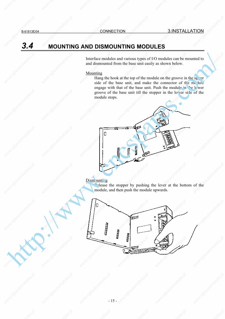
3.4 MOUNTING AND DISMOUNTING MODULES Interface modules and various types of I/O modules can be mounted to and dismounted from the base unit easily as shown below. Mounting Hang the hook at the top of the module on the groove in the upper
side of the base unit, and make the connector of the module engage with that of the base unit. Push the module in the lower groove of the base unit till the stopper in the lower side of the module stops.
Dismounting Release the stopper by pushing the lever at the bottom of the
module, and then push the module upwards.
ht
tp://www.cncspares.com/

4.CONNECTION CONNECTION B-61813E/04
- 16 -
4 CONNECTION
http://www.cncspares.com/

B-61813E/04 CONNECTION 4.CONNECTION
- 17 -
4.1 GENERAL CONNECTION DIAGRAM
NOTE 1 Number of I/O Units and connecting method are restricted depending on the
allocation of the I/O points. Refer to the section 1.2,"Allocation of I/O points." 2 If the master unit is the F-D Mate, one group can consist of up to four I/O Units. 3 Cable K1X can be an optical fiber cable by using the optical I/O link adapter. See chapter 10. 4 Terminator TX is required for connector JD2 of the AIF01B that is the last unit to be
connected in the group. If no AIF01B is in use, no terminator has to be attached to the JD2 connector of the AIF01A or AIF01A2. http://www.cncspares.com/

4.CONNECTION CONNECTION B-61813E/04
- 18 -
4.2 CONNECTING INPUT POWER SOURCE Connect the following power source with the connector CP32 or CP1 of the interface module (AIF01A, AIF01A2, AIF01B, or AIF02C). • Voltage: 24VDC ±10% • Current: Determine from Table 4.4
AIF01A / AIF01B / AIF02C
CP32
AIF01A2
CP1
NOTE Turn ON the power for the I/O Unit just when or
before the power for the CNC or the cell controller is turned ON. When the CNC or cell controller power is turned OFF, make sure to turn the power to the I/O Unit OFF as well. If the power is not turned on and off according to the above procedure, an error occurs in the CNC or the controller, or the I/O Unit is not normally connected to the power.
t ≥ 500 ms (Turn ON of the power for I/O Unit can be late 500 ms or less.)
1 +24V
2 GND
3
Power for the master device
Power for the I/O Unit
24VDC
SORIAU JAPAN (manufactured by former Nippon Burndy) Tri-pole connector (Brown) Housing : SMS3PNS-5 A63L-0001-0202#3LN Contact : RC16M-SCT3 A63L-0001-0226
1 +24V
2 GND
3
24VDC
Tyco Electronics Housing : 1-178288-3 Contact : 1-175218-5 Housing and contact set A02B-0120-K324
http://www.cncspares.com/

B-61813E/04 CONNECTION 4.CONNECTION
- 19 -
4.3 GROUNDING Connect the grounding terminal of the base unit (ABU05A, ABU05B, ABU10A, or ABU10B) to ground. (1) Horizontal type base unit Use a wire of 2 mm2 or more for grounding. (2) Vertical type base unit
(a) For metal case (early shipment)
NOTE Connect the grounding terminal to the grounding hole
portion.
(b) For plastic case (2) When the cable K1X (See overall connection figure in section 4.1)
runs between different cabinets, make sure to connect the cabinets with a wire more than 5.5 mm2.
Grounding terminal(M3 screw terminal)
M4 hole for grounding
Grounding terminal(M3 screw terminal)
http://www.cncspares.com/

4.CONNECTION CONNECTION B-61813E/04
- 20 -
4.4 REQUIRED CURRENT
Table 4.4 Required current of each module Required current (mA) of+24V Module name
A B AIF01A 50 AIF01A2 50 AIF01B 50 AIF02C 50
AID32A1 20+0.5×n 30+7.5×n AID32B1 20+0.5×n 30+7.5×n AID32H1 20+0.5×n 30+7.5×n AID16C 5 AID16K 5 AID16D 5 AID16L 5
AID32E1 5 AID32E2 5 AID32F1 5 AID32F2 5 AIA16G 5+1.5×n
AOD32A1 14 AOD08C 5+2×n AOD08D 5+2×n
AOD08DP 5+2×n AOD16C 5+2×n AOD16D 5+2×n
AOD16D2 5+2×n AOD16D3 5+2×n AOD16DP 5+2×n AOD32C1 5+0.5×n AOD32C2 5+0.5×n AOD32D1 5+0.5×n AOD32D2 5+0.5×n AOA05E 5+5.5×n AOA08E 5+5.5×n AOA12F 5+4.5×n AOR08G 5 10×n AOR16G 5 10×n AOR16H2 5 10×n
Input 20+0.5×n 30+7.5×n AIO40A Output 5+0.5×n AAD04A 5 130 AAD04B 5 130 ADA02A 6 120 ADA02B 6 130 ACT01A 170+0.3×α ATI04A 62.5 100 ATI04B 62.5 100
n: Number of the input and output points (for each module) which turn ON simultaneously
α: +5-V current (mA) output to the outside • Add the sums of the columns A and B for the modules to be used.
The sum is the required current.(Unit: mA) • For each base unit, keep the sum of column A and the sum of
column B to within 500 mA and 1,500 mA, respectively.
http://www.cncspares.com/
B-61813E/04 CONNECTION 4.CONNECTION
- 21 -
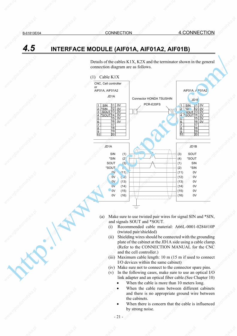
4.5 INTERFACE MODULE (AIF01A, AIF01A2, AIF01B) Details of the cables K1X, K2X and the terminator shown in the general connection diagram are as follows. (1) Cable K1X
*SIN SOUT
0V
0V0V
11
1312
1615
1817
1920
SIN
*SOUT
1
32
4
65
87
910
CNC, Cell controller or AIF01A, AIF01A2
JD1A
11
1312
1615
1817
1920
*SIN SIN
*SOUT
1
3 2
4
6 5
8 7
9 10
SOUT 14 14
AIF01A, AIF01A2
JD1B
0V
0V0V
0V
0V0V
0V
0V0V
JD1A JD1B
SIN (1) *SIN (2) SOUT (3) *SOUT (4) 0V (11) 0V (12) 0V (13) 0V (14) 0V (15) 0V (16)
(3) SOUT (4) *SOUT (1) SIN (2) *SIN (11) 0V (12) 0V (13) 0V (14) 0V (15) 0V (16) 0V
Connector HONDA TSUSHIN
PCR-E20FS
(a) Make sure to use twisted pair wires for signal SIN and *SIN,
and signals SOUT and *SOUT. (i) Recommended cable material: A66L-0001-0284#10P
(twisted pair/shielded) (ii) Shielding wires should be connected with the grounding
plate of the cabinet at the JD1A side using a cable clamp. (Refer to the CONNECTION MANUAL for the CNC and the cell controller.)
(iii) Maximum cable length: 10 m (15 m if used to connect I/O devices within the same cabinet)
(iv) Make sure not to connect to the connector spare pins. (v) In the following cases, make sure to use an optical I/O
link adapter and an optical fiber cable.(See Chapter 10) • When the cable is more than 10 meters long. • When the cable runs between different cabinets
and there is no appropriate ground wire between the cabinets.
• When there is concern that the cable is influenced by strong noise.
http://www.cncspares.com/

4.CONNECTION CONNECTION B-61813E/04
- 22 -
(vi) When an optical I/O link adapter is used: Cable to be used between the interface module (AIF01A) and the optical I/O link adapter is dissimilar to this cable. (See Chapter 10.)
(2) Cable K2X
• Connect the signals with a same name. • Make sure to use twisted pair wires for the following signals:
S1 and * S1, S2 and *S2, S3 and *S3 S4 and * S4, S5 and *S5, S6 and *S6
• Do not connect the pins No.10, No.19 and No.20 as they are used internally.
• Recommended cable material: A66L-0001-0284#10P (twisted pair/shielded)
• Maximum cable length: 2m
AIF01B AIF01A, AIF01A2, or AIF01B
http://www.cncspares.com/

B-61813E/04 CONNECTION 4.CONNECTION
- 23 -
(3) Terminator TX Ordering information : A03B-0807-K806
• If no AIF01B is in use, the TX terminator does not have to be attached to the JD2 connector of the AIF01A or AIF01A2.
• If at least one AIF01B is in use, attach the terminator to the JD2 connector of the last AIF01B in the same group.
• Short-circuit the TRM1s, the TRM2s and the TRM3s one another respectively in a manner that a TRM1 is with another TRM1 and so on.
Short-circuit
http://www.cncspares.com/

4.CONNECTION CONNECTION B-61813E/04
- 24 -
4.6 INTERFACE MODULE (AIF02C) CONNECTION
4.6.1 Overview One interface module (AIF02C) can control communication with both I/O Unit-A and Unit-B, when it is connected to the FANUC I/O Link. The following examples show a configuration in which two conventional separate interface modules, I/O Unit-A and I/O Unit-B, are used and a configuration in which the AIF02C is used.
CNC cell controller
Group #0
Group #1
Base expansion
(Note 2)
To the next group DI/DO unit DI/DO unit DI/DO unit DI/DO unit
CNC cell controller
(Note 2)
DI/DO unit To the next group
Group #0
Group #1
(NOTE 1)
Base expansion
DI/DO unit DI/DO unit DI/DO unit
(1) Configuration example in which separate interface modules are used
(2) Configuration example in which AIF02C is used
AIF01A AIF01A2
http://www.cncspares.com/

B-61813E/04 CONNECTION 4.CONNECTION
- 25 -
In this way, using the AIF02C eliminates the necessity for the interface unit (BIF04A1) for I/O Unit-B, which has conventionally been used separately; this configuration is suitable for a small I/O Unit-B system. Note the following points.
NOTE 1 The AIF02C cannot be used for base expansion. 2 The BIF04A1 can branch to a maximum of eight
communication lines. The AIF02C can branch only to a maximum of two
distributed link cables.
4.6.2 Connection (1) Connection diagram
[a] Configuration with two distributed link cables (note the setting of the terminating resistor.)
DI/DO unit
(From group n-1)
Groups n and n+1
DI/DO unit DI/DO unit
DI/DO unit DI/DO unit DI/DO unit
(To group n+2)
Distributed link
NOTE *1 Set the terminating resistor DIP switch to ON. *2 Set the terminating resistor DIP switch to OFF.
[b] Connection with one distributed link cable (note the setting
of the terminating resistor.) (From group n-1)
Groups n and n+1
(To group n+2)
Distributed link
DI/DO unit DI/DO unit DI/DO unit
NOTE *1 Set the terminating resistor DIP switch to ON. *2 Set the terminating resistor DIP switch to OFF.
http://www.cncspares.com/

4.CONNECTION CONNECTION B-61813E/04
- 26 -
(2) Connection with the I/O Link The AIF02C occupies two groups on the I/O Link. When groups #n and #n+1 are used, for example, the
smaller-numbered group, #n, is assigned to the I/O Unit-A, and the larger-numbered group, #n+1, is assigned to the I/O Unit-B. [a] Connection of the I/O link cable Connect the I/O link cable from the previous group to JD1B.
Connect JD1A to the I/O link cable leading to the next group. Use the K1X I/O link signal cable, the same I/O link signal cable type as that for the AIF01A.
[b] Number of occupied I/O points on the I/O link The nominal number of occupied I/O points may differ from
the actual number of I/O points. For the details of the number of I/O points occupied by the I/O
Unit-B, refer to Section 4.3.1, "Number of points occupied on the interface unit I/O link," of the FANUC I/O Unit-B MODEL Connection Manual (B-62163E).
(3) Connection with the distributed link (I/O Unit-B)
[a] Number of distributed communication lines "T1" can connect to two communication lines (twisted-pair
wires). So, it is possible to branch to up to two lines. To branch to more lines, you should use the I/O Unit-B
interface unit (BIF04A1), which enables branching to up to eight communication lines.
[b] Terminal board "T1," used for connection with the distributed link cable
The distributed link cable is connected to "T1."
AIF02C
T1
<1> Use twisted-pair wires as the distributed link cable. <2> The distributed link cable is polarity-sensitive. Match
the signal polarity of the AIF02C with that of the basic unit.
<3> The terminal board has M3 screws with a terminal cover.
Refer to Section 4.4, "Connecting a Distributed Link," and Section 4.6.2.2, "Connecting the communications cable," of the FANUC I/O Unit-MODEL B Connection Manual (B-62163E) for details.
1 S+
2 S-
3 FG
http://www.cncspares.com/

B-61813E/04 CONNECTION 4.CONNECTION
- 27 -
4.6.3 Setting with the DIP Switch In the AIF02C, distributed link settings can be made with the DIP switch on the back of the module. The settings and corresponding signals are shown below.
1 2 Unused
3 4 EDSP 5 Q 6 H 7 URDY 8 R
(1) EDSP (error display method selection) Normally, set EDSP to the ON position. (2) Q and H (communication speed setting) Normally, set both Q and H to the OFF positions. (3) URDY (setting of the power on/off information for the unit) Normally, set URDY to the OFF position. (4) R (terminating resistor setting) The ON position means that a terminating resistor must be
installed. The OFF position means that no terminating resistor need be installed.
When only one communication cable is connected to the AIF02C, terminate it and the basic unit at the end of the communication cable with a resistor.
When two communication cables are connected to the AIF02C, terminate the basic unit connected to the end of each communication cable with a resistor. Do not connect a terminating resistor to the AIF02C. (Refer to Section 4.6.2, "Connection.")
Refer to Section 5.1.1, "DIP switch setting," of the FANUC I/O Unit-MODEL B CONNECTION MANUAL (B-62163E).
http://www.cncspares.com/

4.CONNECTION CONNECTION B-61813E/04
- 28 -
4.7 CONNECTING WITH I/O MODULES From the point of view of an external connecting method, there are two types of I/O modules such as one with a terminal block and one with a connector.
A 0 . . . 7 B 0 . . . 7
Specification of the terminalblock on the module BL3.5//24/90F
Terminal block manufactured by Weidmüller (used in the AOD16D3)
Input/output display LED
The following three different connectors can be used on the connector-type module.
Specification of the connector on the module Module name
AID32A1 AID32B1 AID32H1 AID32E1 AID32F1
AOD32A1 AOD32C1 AOD32D1
Manufactured by HONDA TSUSHIN MR-50RMA
AIO40A AID32E2 AID32F2
AOD32C2 AOD32D2
Manufactured by HIROSE ELECTRIC HIF3BB-50PA-2.54DS
AOR16H2 Manufactured by HIROSE ELECTRIC
HIF4-40P-3.18DS AOD16D2
http://www.cncspares.com/

B-61813E/04 CONNECTION 4.CONNECTION
- 29 -
(1) Connect with each module following the connection diagrams of Sections 4.2 and 5.3.
(2) The terminal block is a removable type.
[Dismounting the terminal block] <1> Open the cover of the terminal
block. <2> Push up the latch at the top of the
terminal block. <3> Drag out the tab at the top of the
terminal block and pull it out. The terminal block will be removed from the module.
[Mounting the terminal block] <1> Insert the protruding portion at
the bottom of the terminal block in the groove of the module side.
<2> Push the terminal block using the engaging point of the protruding portion and the groove as an axis and mount it in the module firmly.
<3> Open the cover of the terminal block and check to make sure the latch at the top of the terminal block is firmly set.
(3) Cautionary points when wiring terminal block type
• Wiring material : AWG22 to 18 (0.3 to 0.75 mm2) A wire as this as possible is recommended. • Crimp style terminal : M3.5 Crimp style terminal with no
insulation sleeve and a short distance "A", as illustrated in the drawing below, is recommended.
DAIDO SOLDERLESS TERMINAL 1.25-S3.5 NICHIFU 1.25-3.5S etc.
• Mark tube : Use a short mark tube as possible and cover
crimped part with the mark tube. • Recommended tightening torque : 1 to 1.4 N⋅m
(4) Wiring to the terminal block manufactured by Weidmüller
• Wire with a cross section of 0.08 to 1.5 mm2 (VDE)/AWG28 to AWG14 (UL/CSA)
• Recommended tightening torque: 0.8 N⋅m • Size conformable when a ferrule (rod terminal) is used: 0.5 to
1.5 mm2
Peeling length: 6 mm
http://www.cncspares.com/

5.DIGITAL INPUT/OUTPUT MODULESCONNECTION B-61813E/04
- 30 -
5 DIGITAL INPUT/OUTPUT MODULES
http://www.cncspares.com/

B-61813E/04 CONNECTION5.DIGITAL INPUT/OUTPUT MODULES
- 31 -
5.1 LIST OF MODULES
(1) Digital input modules
Input type
Module name
Rated voltage
Rated current
Polarity*1 Response time Points
External connection
*2 LED display
AID32A1 24VDC 7.5mA Both Maximum 20msec 32 Connector A Not providedAID32B1 24VDC 7.5mA Both Maximum 2msec 32 Connector A Not provided
Non- insulation type DC
input AID32H1 24VDC 7.5mA Both Maximum 2msec
Maximum 20msec 8 24
Connector A Not provided
AID16C 24VDC 7.5mA NEG Maximum 20msec 16 Terminal block Provided AID16K 24VDC 7.5mA NEG Maximum 2msec 16 Terminal block Provided AID16D 24VDC 7.5mA POS Maximum 20msec 16 Terminal block Provided AID16L 24VDC 7.5mA POS Maximum 2msec 16 Terminal block Provided
AID32E1 24VDC 7.5mA Both Maximum 20msec 32 Connector A Not providedAID32E2 24VDC 7.5mA Both Maximum 20msec 32 Connector B Not providedAID32F1 24VDC 7.5mA Both Maximum 2msec 32 Connector A Not provided
Insulation type DC
input
AID32F2 24VDC 7.5mA Both Maximum 2msec 32 Connector B Not provided
AC input AIA16G 100 to
120VAC10.5mA
(120VAC) -
ON: Maximum 35msecOFF: Maximum 45msec
16 Terminal block Provided
+
-
NEG circuit example
Input pin
Common pin
Current
Input module
POS circuit example
+
-
Current
Input pin
Common pin
Input module NOTE 1 Polarity NEGative : (Current source type, source type, or Nch)
Regard to be ON when input is at Low level. POSitive : (Current sink type, sink type, or Pch)
Regard to be ON when input is High level. 2 Connectors (Section 5.4 shows a connector signal arrangement diagram as viewed
from the front of the module.) Connector A : HONDA TSUSHIN MR-50RMA connector
It is recommended that the MR-50LW (housing) and MR50-FH (soldering-type connector) or MRP-50F01 (crimp connector) + MRP-F112 (contact) be used on the cable.
Connector B : HIROSE ELECTRIC HIF3BB-50PA-2.54DS It is recommended that the HIF3BB-50D-2.54R (press-mount connector) be used on the cable.
3 For the details of the specifications for each module, refer to the section 5.3.
http://www.cncspares.com/

5.DIGITAL INPUT/OUTPUT MODULESCONNECTION B-61813E/04
- 32 -
(2) Digital output modules
Output type Module name Rated
voltage Maximum
current Polarity
*1 PointsPoints/
common
External connection
*2
LED display
Output protection
Non-insulation type DC output AOD32A1 5 to 24VDC 0.3A NEG 32 8 Connector A
Not provided Not provided
AOD08C 2A NEG 8 8 Terminal block Provided Fuse AOD08D 2A POS 8 8 Terminal block Provided Fuse
AOD08DP 2A POS 8 8 Terminal block Provided Output
protection device
AOD16C 0.5A NEG 16 8 Terminal block Provided Not providedAOD16D 0.5A POS 16 8 Terminal block Provided Not provided
AOD16D2 2A POS 16 4 Connector C Provided Not provided
AOD16D3 2A POS 16 4 Terminal block
B Provided Fuse
AOD16DP 0.3A POS 16 8 Terminal block Provided Output
protection device
AOD32C1 0.3A NEG 32 8 Connector A Not
provided Not provided
AOD32C2 0.3A NEG 32 8 Connector B Not
provided Not provided
AOD32D1 0.3A POS 32 8 Connector A Not
provided Not provided
Insulation type DC output
AOD32D2
12 to 4VDC
0.3A POS 32 8 Connector B Not
provided Not provided
AOA05E 2A - 5 1 Terminal block Provided Fuse AOA08E
100 to 240VAC 1A - 8 4 Terminal block Provided Fuse AC output
AOA12F 100 to
120VAC 0.5A - 12 6 Terminal block Provided Fuse
AOR08G 4A - 8 1 Terminal block Provided Not provided
AOR16G
Maximum 250VAC / 30VDC 2A - 16 4 Terminal block Provided Not providedRELAY output
AOR16H2 30VDC 2A - 16 4 Connector B Provided Not provided
(3) Digital input/output hybrid module
Input/output
type Module name Rated
voltage SpecificationPolarity
*1 PointsPoints/
common
External connection
*2
LED display
Output protection
Non-insulation type DC input 24VDC
Current rating: 7.5 mA
Response time: 20 ms (maximum)
Both 24 24
Non-insulation type DC output
AIO40A
24VDC
Maximum current:
0.2 A/point and 2A for common
NEG 16 16
Connector A (shared by input
and output signals)
Not provided Not provided
http://www.cncspares.com/

B-61813E/04 CONNECTION5.DIGITAL INPUT/OUTPUT MODULES
- 33 -
NEG circuit example
Output pin
Common pin
+
- Current
Output module Load
+24V
0V
POS circuit example
Output module
Output pin
Common pin
+
-
Current
Load
+24V
0V
NOTE 1 Polarity NEGative : (Current sink type) Output is at Low level when ON. POSitive : (Current source type) Output is at High level when ON. 2 Connector and terminal block B (Section 5.4 shows a connector signal arrangement diagram as viewed from the front
of the module.) Connector A : HONDA TSUSHIN MR-50RMA connector
It is recommended that the MR-50LW (housing) and MR50-FH (soldering-type connector) or MRP-50F01 (crimp connector) + MRP-F112 (contact) be used on the cable.
Connector B : HIROSE ELECTRIC HIF3BB-50PA-2.54DS It is recommended that the HIF3BB-50D-2.54R (press-mount connector) be used on the cable.
Connector C : HIROSE ELECTRIC HIF4-40P-3.18DS It is recommended that the HIF4-40D-3.18R (press-mount connector) be used on the cable.
Terminal block B : Weidmüller BL3.5/24/90F The terminal block for the cable comes with the module.
3 For the details of the specifications for each module, refer to the section 5.3. 4 The maximum current of the DC output module includes the permissible rush current.
http://www.cncspares.com/

5.DIGITAL INPUT/OUTPUT MODULESCONNECTION B-61813E/04
- 34 -
5.2 CORRESPONDENCE BETWEEN I/O SIGNALS AND ADDRESSES IN A MODULE
The term "address in a module" refers to an address allocated within each DI/DO module and relative to the start address (Xm, Yn) of the module.
5.2.1 Module with 16/32 Digital Inputs (DI)
Address in the module
7 6 5 4 3 2 1 0 Xm A7 A6 A5 A4 A3 A2 A1 A0
Xm+1 B7 B6 B5 B4 B3 B2 B1 B0
Xm+2 C7 C6 C5 C4 C3 C2 C1 C0
Xm+3 D7 D6 D5 D4 D3 D2 D1 D0 When a contact connected to an input of an input module is closed, the corresponding input signal becomes "1".
5.2.2 Module with 5/8/12/16/32 Digital Outputs (DO)
Address in the module
7 6 5 4 3 2 1 0 Yn A7 A6 A5 A4 A3 A2 A1 A0
Yn+1 B7 B6 B5 B4 B3 B2 B1 B0
Yn+2 C7 C6 C5 C4 C3 C2 C1 C0
Yn+3 D7 D6 D5 D4 D3 D2 D1 D0 When the output signal from an output module is "1", the corresponding output contact (or transistor) is closed.
DI module of 16 points
DI module of 32 points
Input bits
DO module of 12 and 16 points
DO module of 32 points
Output bitsDO module of 5 and 8 points
http://www.cncspares.com/
B-61813E/04 CONNECTION5.DIGITAL INPUT/OUTPUT MODULES
- 35 -
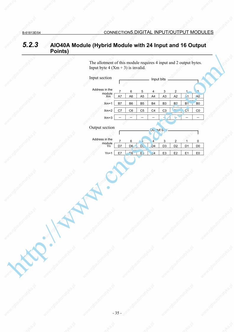
5.2.3 AIO40A Module (Hybrid Module with 24 Input and 16 Output Points)
The allotment of this module requires 4 input and 2 output bytes. Input byte 4 (Xm + 3) is invalid. Input section
Address in the module
7 6 5 4 3 2 1 0 Xm A7 A6 A5 A4 A3 A2 A1 A0
Xm+1 B7 B6 B5 B4 B3 B2 B1 B0
Xm+2 C7 C6 C5 C4 C3 C2 C1 C0
Xm+3 - - - - - - - - Output section
Address in the module
7 6 5 4 3 2 1 0 Yn D7 D6 D5 D4 D3 D2 D1 D0
Yn+1 E7 E6 E5 E4 E3 E2 E1 E0
Input bits
Output bits
http://www.cncspares.com/

5.DIGITAL INPUT/OUTPUT MODULESCONNECTION B-61813E/04
- 36 -
5.3 SPECIFICATION FOR EACH MODULE Specifications for the module are shown in the following pages. (1) Input module AID32A1 (2) Input module AID32B1 (3) Input module AID32H1 (4) Input module AID16C (5) Input module AID16K (6) Input module AID16D (7) Input module AID16L (8) Input module AID32E1 (9) Input module AID32E2 (10) Input module AID32F1 (11) Input module AID32F2 (12) Input module AIA16G (13) Output module AOD32A1 (14) Output module AOD08C (15) Output module AOD08D (16) Output module AOD08DP (17) Output module AOD16C (18) Output module AOD16D (19) Output module AOD16D2 (20) Output module AOD16D3 (21) Output module AOD16DP (22) Output module AOD32C1 (23) Output module AOD32C2 (24) Output module AOD32D1 (25) Output module AOD32D2 (26) Output module AOA05E (27) Output module AOA08E (28) Output module AOA12F (29) Output module AOR08G (30) Output module AOR16G (31) Output module AOR16H2 (32) Input/output module AIO40A
http://www.cncspares.com/

B-61813E/04 CONNECTION5.DIGITAL INPUT/OUTPUT MODULES
- 37 -
(1) Input module AID32A1 (Non-insulation type)
Item Specifications Points/module 32 points Points/common 16 points/common Sink/source current Both directions Input voltage 24VDC +10%, −20% Input current 7.5mA (average) ON voltage, current Min. 18VDC, min. 6mA OFF voltage, current Max. 6VDC, max. 1.5mA
OFF→ON Max.20ms Response time ON→OFF Max.20ms
This is the value from input to output in the module. The actual value isdetermined by adding it to the scanning time depending on each system.
Input display Not provided External connection Connector (HONDA TSUSHIN MR-50RMA) Terminal connection and circuitry
+24V or GND can be selected for input common as above fig.
NOTE 1 Make sure to connect all common (CMA, CMC) pins.2 This module outputs +24 V on pins 13, 17, 04, and 08.
http://www.cncspares.com/

5.DIGITAL INPUT/OUTPUT MODULESCONNECTION B-61813E/04
- 38 -
(2) Input module AID32B1 (Non-insulation type)
Item Specifications Points/module 32 points Points/common 16 points/common Sink/source current Both directions Input voltage 24VDC +10%, −20% Input current 7.5mA (average) ON voltage, current Min. 18VDC, min. 6mA OFF voltage, current Max. 6VDC, max. 1.5mA
OFF→ON Max.2ms Response time ON→OFF Max.2ms
This is the value from input to output in the module. The actual value isdetermined by adding it to the scanning time depending on each system.
Input display Not provided External connection Connector (HONDA TSUSHIN MR-50RMA) Terminal connection and circuitry
+24V or GND can be selected for input common as above fig.
NOTE 1 Make sure to connect all common (CMA, CMC) pins.2 This module outputs +24 V on pins 13, 17, 04, and 08.
http://www.cncspares.com/

B-61813E/04 CONNECTION5.DIGITAL INPUT/OUTPUT MODULES
- 39 -
(3) Input module AID32H1
Item Specifications Points/module 32 points Points/common 16 points/common Sink/source current Both directions Input voltage 24VDC +10%, −20% Input current 7.5mA (average) ON voltage, current Min. 18VDC, min. 6mA OFF voltage, current Max. 6VDC, max. 1.5mA
OFF→ON Max.2ms (A0 to A7) Max.20ms (B0 to D7)
Response time
ON→OFF Max.2ms (A0 to A7) Max.20ms (B0 to D7)
This is the value from input to output in the module. The actual value is determined by adding it to the scanning time dependingon each system.
Input display Not provided External connection Connector (HONDA TSUSHIN MR-50RMA) Terminal connection and circuitry
+24V or GND can be selected for input common as above fig.
NOTE 1 Make sure to connect all common (CMA, CMC) pins.2 This module outputs +24 V on pins 13, 17, 04, and 08.
http://www.cncspares.com/

5.DIGITAL INPUT/OUTPUT MODULESCONNECTION B-61813E/04
- 40 -
(4) Input module AID16C
Item Specifications Points/module 16 points Points/common 16 points/common Sink/source current Source current type Input voltage 24VDC +10%, −20% Input current 7.5mA (average) ON voltage, current Min. 15VDC, min. 4mA OFF voltage, current Max. 5VDC, max. 1.5mA
OFF→ON Max.20ms Response time ON→OFF Max.20ms
This is the value from input to output in the module. The actual value isdetermined by adding it to the scanning time depending on each system.
Input display LED display External connection Terminal block connector (20 terminals, M3.5 screw terminal) Terminal connection and circuitry
NOTE Pins 18 and 19 are for factory use only. Do not connect any wire to them
(Note)
http://www.cncspares.com/

B-61813E/04 CONNECTION5.DIGITAL INPUT/OUTPUT MODULES
- 41 -
(5) Input module AID16K
Item Specifications Points/module 16 points Points/common 16 points/common Sink/source current Source current type Input voltage 24VDC +10%, −20% Input current 7.5mA (average) ON voltage, current Min. 15VDC, min. 4mA OFF voltage, current Max. 5VDC, max. 1.5mA
OFF→ON Max.2ms Response time ON→OFF Max.2ms
This is the value from input to output in the module. The actual value isdetermined by adding it to the scanning time depending on each system.
Input display LED display External connection Terminal block connector (20 terminals, M3.5 screw terminal) Terminal connection and circuitry
NOTE Pins 18 and 19 are for factory use only. Do not connect any wire to them
(Note)
http://www.cncspares.com/

5.DIGITAL INPUT/OUTPUT MODULESCONNECTION B-61813E/04
- 42 -
(6) Input module AID16D
Item Specifications Points/module 16 points Points/common 16 points/common Sink/source current Sink current type Input voltage 24VDC +10%, −20% Input current 7.5mA (average) ON voltage, current Min. 15VDC, min. 4mA OFF voltage, current Max. 5VDC, max. 1.5mA
OFF→ON Max.20ms Response time ON→OFF Max.20ms
This is the value from input to output in the module. The actual value is determined by adding it to the scanning time depending on each system.
Input display LED display External connection Terminal block connector (20 terminals, M3.5 screw terminal) Terminal connection and circuitry
NOTE Pins 18 and 19 are for factory use only. Do not connect any wire to them
(Note)
http://www.cncspares.com/

B-61813E/04 CONNECTION5.DIGITAL INPUT/OUTPUT MODULES
- 43 -
(7) Input module AID16L
Item Specifications Points/module 16 points Points/common 16 points/common Sink/source current Sink current type Input voltage 24VDC +10%, −20% Input current 7.5mA (average) ON voltage, current Min. 15VDC, min. 4mA OFF voltage, current Max. 5VDC, max. 1.5mA
OFF→ON Max.2ms Response time ON→OFF Max.2ms
This is the value from input to output in the module. The actual value is determined by adding it to the scanning time depending on each system.
Input display LED display External connection Terminal block connector (20 terminals, M3.5 screw terminal) Terminal connection and circuitry
NOTE Pins 18 and 19 are for factory use only. Do not connect any wire to them
(Note)
http://www.cncspares.com/

5.DIGITAL INPUT/OUTPUT MODULESCONNECTION B-61813E/04
- 44 -
(8) Input module AID32E1
Item Specifications Points/module 32 points Points/common 8 points/common Sink/source current Both directions Input voltage 24VDC +10%, −20% Input current 7.5mA (average) ON voltage, current Min. 15VDC, min. 4.5mA OFF voltage, current Max. 6VDC, max. 2mA
OFF→ON Max.20ms Response time ON→OFF Max.20ms
This is the value from input to output in the module. The actual value is determined by adding it to the scanning time depending on each system.
Input display Not provided External connection Connector (HONDA TSUSHIN MR-50RMA) Terminal connection and circuitry
http://www.cncspares.com/

B-61813E/04 CONNECTION5.DIGITAL INPUT/OUTPUT MODULES
- 45 -
(9) Input module AID32E2
Item Specifications Points/module 32 points Points/common 8 points/common Sink/source current Both directions Input voltage 24VDC +10%, −20% Input current 7.5mA (average) ON voltage, current Min. 15VDC, min. 4.5mA OFF voltage, current Max. 6VDC, max. 2mA
OFF→ON Max.20ms Response time ON→OFF Max.20ms
This is the value from input to output in the module. The actual value is determined by adding it to the scanning time depending on each system.
Input display Not provided External connection Connector (HIROSE ELECTRIC HIF3BB-50PA-2.54DS in accordance with MIL
standard) Terminal connection and circuitry
http://www.cncspares.com/

5.DIGITAL INPUT/OUTPUT MODULESCONNECTION B-61813E/04
- 46 -
(10) Input module AID32F1
Item Specifications Points/module 32 points Points/common 8 points/common Sink/source current Both directions Input voltage 24VDC +10%, −20% Input current 7.5mA (average) ON voltage, current Min. 15VDC, min. 4.5mA OFF voltage, current Max. 6VDC, max. 2mA
OFF→ON Max.2ms Response time ON→OFF Max.2ms
This is the value from input to output in the module. The actual value is determined by adding it to the scanning time depending on each system.
Input display Not provided External connection Connector (HONDA TSUSHIN MR-50RMA) Terminal connection and circuitry
http://www.cncspares.com/

B-61813E/04 CONNECTION5.DIGITAL INPUT/OUTPUT MODULES
- 47 -
(11) Input module AID32F2
Item Specifications Points/module 32 points Points/common 8 points/common Sink/source current Both directions Input voltage 24VDC +10%, −20% Input current 7.5mA (average) ON voltage, current Min. 15VDC, min. 4.5mA OFF voltage, current Max. 6VDC, max. 2mA
OFF→ON Max.2ms Response time ON→OFF Max.2ms
This is the value from input to output in the module. The actual value is determined by adding it to the scanning time depending on each system.
Input display Not provided External connection Connector (HIROSE ELECTRIC HIF3BB-50PA-2.54DS in accordance with MIL
standard) Terminal connection and circuitry
http://www.cncspares.com/

5.DIGITAL INPUT/OUTPUT MODULESCONNECTION B-61813E/04
- 48 -
(12) Input module AIA16G
Item Specifications Points/module 16 points Points/common 16 points/common Sink/source current 100 to 115VAC ±15% Input voltage 132Vrms, 50/60 Hz Input current 10.55mArms (120VAC, 50Hz) ON voltage, current Min. 74Vrms, min. 6mArms OFF voltage, current Max. 20Vrms, max. 2.2mArms
OFF→ON Max.35ms Response time ON→OFF Max.45ms
This is the value from input to output in the module. The actual value is determined by adding it to the scanning time depending on each system.
Input display LED display External connection Terminal block connector (20 terminals, M3.5 screw terminal) Common 16 points/common Terminal connection and circuitry
http://www.cncspares.com/

B-61813E/04 CONNECTION5.DIGITAL INPUT/OUTPUT MODULES
- 49 -
(13) Output module AOD32A1 (Non-insulation type)
Item Specifications Points/module 32 points Points/common 8 points/common Sink/source current Sink current type Rated load voltage 5 to 24VDC +20%, −15% Maximum load current 0.3A (however 2A/common) Maximum voltage drop when ON 0.24V (load current ×0.8Ω) Maximum leak current when OFF 0.1mA
OFF→ON Max.1ms Response time ON→OFF Max.1ms
Input display Not provided External connection Connector (HONDA TSUSHIN MR-50RMA) Terminal connection and circuitry
NOTE For the common (CMA, CMB, CMC, CMD) , make
sure to use both of them. ht
tp://www.cncspares.com/

5.DIGITAL INPUT/OUTPUT MODULESCONNECTION B-61813E/04
- 50 -
(14) Output module AOD08C
Item Specifications Points/module 8 points Points/common 8 points/common Sink/source current Sink current type Rated load voltage 12 to 24VDC +20%, −15% Maximum load current 2A (however 4A/fuse) Maximum voltage drop when ON 0.8V (load current ×0.4Ω) Maximum leak current when OFF 0.1mA
OFF→ON Max.2ms Response time ON→OFF Max.2ms
This is the value from input to output in the module. The actual value is determined by adding it to the scanning time depending on each system.
Input display LED display External connection Terminal block connector (20 terminals, M3.5 screw terminal) Fuse 5A, 1 piece for each output A0-A3 and A4-A7. Terminal connection and circuitry
http://www.cncspares.com/

B-61813E/04 CONNECTION5.DIGITAL INPUT/OUTPUT MODULES
- 51 -
(15) Output module AOD08D
Item Specifications Points/module 8 points Points/common 8 points/common Sink/source current Source current type Rated load voltage 12 to 24VDC +20%, −15% Maximum load current 2A (however 4A/fuse) Limit of load Refer to load derating curve (Fig. 5.3(a)) Maximum voltage drop when ON 1.2V (load current ×0.6Ω) Maximum leak current when OFF 0.1mA
OFF→ON Max.2ms Response Time ON→OFF Max.2ms
This is the value from input to output in the module. The actual value is determined by adding it to the scanning time depending on each system.
Output display LED display External connection Terminal block connector (20 terminals, M3.5 screw terminal) Fuse 5A, 1 piece for each output A0-A3 and A4-A7. Terminal connection and circuitry
http://www.cncspares.com/

5.DIGITAL INPUT/OUTPUT MODULESCONNECTION B-61813E/04
- 52 -
(16) Output module AOD08DP
Item Specifications Points/module 8 points Points/common 8 points/common Sink/source current Source current type Rated load voltage 12 to 24VDC +20%, −15% Maximum load current 2A (however 8A/common) Output current limit 2.8A (Min.) Maximum voltage drop when ON 0.18V (load current ×0.09Ω) Maximum leak current when OFF 0.1mA
OFF→ON Max.2ms Response Time ON→OFF Max.2ms
This is the value from input to output in the module. The actual value is determined by adding it to the scanning time depending on each system.
Output display LED display External connection Terminal block connector (20 terminals, M3.5 screw terminal) Terminal connection and circuitry
Output circuit
Internal circuit
Load
http://www.cncspares.com/

B-61813E/04 CONNECTION5.DIGITAL INPUT/OUTPUT MODULES
- 53 -
• AOD08DP output protection
The internal circuit of this output module can detect a load overcurrent and driver temperature. To be specific, if the load current increases abnormally, for example, because of a wiring ground fault, the internal limiter of the driver suppresses the output current. If this condition lasts long, the driver can get abnormally hot, thus causing the protection circuit to turn off the output. After the output is turned off and the driver temperature becomes lower, the protection function is automatically reset to turn on the output; this OFF/ON operations are repeated.
When the overheat protection circuit works to turn off the output, the LED "F" on the front of the module lights red.
If the protection circuit turns off the output, the output module can detect which DO has encountered the abnormality, using a DI. This function can be allocated to any DI address (1 byte). If an abnormality is detected, the DI bit corresponding to the DO of interest switches between "1" and "0". The DI bit stays "1" for at least 10 ms.
If the protection function worked, turn off the power for both the DO and system, and remove the cause of the overload.
The following timing chart shows how the output and DI
behave when the output protection function works.
Output
DO
DI
10msec or more
7 6 5 4 3 2 1 0 A7 A6 A5 A4 A3 A2 A1 A0
The DI bit having the same bit number as the DO (A0 to A7)
bit where an abnormality was detected becomes "1".
NOTE An overcurrent prolonged, for example, because of
a wiring ground fault may lead to the break-down of a module. To avoid this failure, build a sequence program that can turn off the DO corresponding to the bit number of the DI bit which has been set to "1" because of a failure detected on the driver.
DI(Xm) Bit number
http://www.cncspares.com/

5.DIGITAL INPUT/OUTPUT MODULESCONNECTION B-61813E/04
- 54 -
(17) Output module AOD16C
Item Specifications Points/module 16 points Points/common 8 points/common Sink/source current Sink current type Rated load voltage 12 to 24VDC +20%, −15% Maximum load current 0.5A (however 2A/common) Maximum voltage drop when ON 0.7V (load current ×1.4Ω) Maximum leak current when OFF 0.1mA
OFF→ON Max.2ms Response time ON→OFF Max.2ms
This is the value from input to output in the module. The actual value is determined by adding it to the scanning time depending on each system.
Output display LED display External connection Terminal block connector (20 terminals, M3.5 screw terminal) Terminal connection and circuitry
http://www.cncspares.com/

B-61813E/04 CONNECTION5.DIGITAL INPUT/OUTPUT MODULES
- 55 -
(18) Output module AOD16D
Item Specifications Points/module 16 points Points/common 8 points/common Sink/source current Source current type Rated load voltage 12 to 24VDC +20%, −15% Maximum load current 0.5A (however 2A/common) Maximum voltage drop when ON 0.7V (load current ×1.4Ω) Maximum leak current when OFF 0.1mA
OFF→ON Max.2ms Response time ON→OFF Max.2ms
This is the value from input to output in the module. The actual value is determined by adding it to the scanning time depending on each system.
Output display LED display External connection Terminal block connector (20 terminals, M3.5 screw terminal) Terminal connection and circuitry
http://www.cncspares.com/

5.DIGITAL INPUT/OUTPUT MODULESCONNECTION B-61813E/04
- 56 -
(19) Output module AOD16D2
Item Specifications Points/module 16 points Points/common 4 points/common Sink/source current Source current type Rated load voltage 12 to 24VDC +20%, −15% Maximum load current 2A (4A/common) Maximum voltage drop when ON 0.4V (load current ×0.2Ω) Maximum leak current when OFF 0.1mA
OFF→ON Max.2ms Response time ON→OFF Max.2ms
This is the value from input to output in the module. The actual value is determined by adding it to the scanning time depending on each system.
Output display LED display External connection Connector (HIROSE ELECTRIC HIF4-40P-3.18DS) Terminal connection and circuitry
Output circuit
Internal circuit
Load
Output terminalhttp://www.cncspares.com/

B-61813E/04 CONNECTION5.DIGITAL INPUT/OUTPUT MODULES
- 57 -
(20) Output module AOD16D3
Item Specifications Points/module 16 points Points/common 4 points/common Sink/source current Source current type Rated load voltage 12 to 24VDC +20%, −15% Maximum load current 2A (4A/common) Maximum voltage drop when ON 0.4V (load current ×0.2Ω) Maximum leak current when OFF 0.1mA
OFF→ON Max.2ms Response time ON→OFF Max.2ms
This is the value from input to output in the module. The actual value is determined by adding it to the scanning time depending on each system.
Output display LED display External connection 24-pin terminal block (BL3.5/24/90F) manufactured by Weidmüler
Conformable wire (maximum): 1.5 mm2 (VDE)/AWG 14 (UL/CSA) Note: The terminal block for the cable comes with this module.
Fuse One 5A fuse for each of output sets A0 to A3, A4 to A7, B0 to B3, and B4 to B7 MP50 (A60L-0001-0046#5.0) manufactured by Daito. Ordering information for a 4-fuse set: A03B-0819-K104
Terminal connection and circuitry
Output circuit
Internal circuit
Load
Output terminal
Fuse
Fuse
Fuse
Fuse
http://www.cncspares.com/

5.DIGITAL INPUT/OUTPUT MODULESCONNECTION B-61813E/04
- 58 -
(21) Output module AOD16DP
Item Specifications Points/module 16 points Points/common 8 points/common Sink/source current Source current type Rated load voltage 12 to 24VDC +20%, −15% Maximum load current 0.3A (2.4A/common)
0.5A (2A/common) See the "Load reduction curve" shown in Fig. 5.3 (f).
Maximum voltage drop when ON 0.63V (load current ×1.25Ω) Maximum leak current when OFF 40µA
OFF→ON Max.2ms Response time ON→OFF Max.2ms
This is the value from input to output in the module. The actual value is determined by adding it to the scanning time depending on each system.
Output display LED display External connection Connector (20 terminals, M3.5 screw terminal) Terminal connection and circuitry
• Output protection The internal circuit of this output module can detect a load overcurrent. To be specific, if the load current increases abnormally, for example, because of a cable ground fault or an internal DO driver is abnormally heated for some reason, the protection circuit for the DO driver (4-point unit) works to keep the output of the DO driver turned off until the cause is removed. When the overheat protection function works, the LED "F" on the module lights.
Output circuit
Internal circuit
Load
Output terminal
http://www.cncspares.com/

B-61813E/04 CONNECTION5.DIGITAL INPUT/OUTPUT MODULES
- 59 -
(22) Output module AOD32C1
Item Specifications Points/module 32 points Points/common 8 points/common Sink/source current Sink current type Rated load voltage 12 to 24VDC +20%, −15% Maximum load current 0.3A (however 2A/common) Maximum voltage drop when ON 0.24V (load current ×0.8Ω) Maximum leak current when OFF 0.1mA
OFF→ON Max.2ms Response time ON→OFF Max.2ms
Output display Not provided External connection Connector (HONDA TSUSHIN MR-50RMA) Terminal connection and circuitry
NOTE For the common (CMA, CMB, CMC, CMD), make
sure to use both of them. ht
tp://www.cncspares.com/

5.DIGITAL INPUT/OUTPUT MODULESCONNECTION B-61813E/04
- 60 -
(23) Output module AOD32C2
Item Specifications Points/module 32 points Points/common 8 points/common Sink/source current Sink current type Rated load voltage 12 to 24VDC +20%, −15% Maximum load current 0.3A (however 2A/common) Maximum voltage drop when ON 0.24V (load current ×0.8Ω) Maximum leak current when OFF 0.1mA
OFF→ON Max.2ms Response time ON→OFF Max.2ms
Output display Not provided External connection Connector (HIROSE ELECTRIC HIF3BB-50PA-2.54DS in accordance with MIL
standard) Terminal connection and circuitry
NOTE For the common (CMA, CMB, CMC, CMD), make
sure to use both of them. ht
tp://www.cncspares.com/

B-61813E/04 CONNECTION5.DIGITAL INPUT/OUTPUT MODULES
- 61 -
(24) Output module AOD32D1
Item Specifications Points/module 32 points Points/common 8 points/common Sink/source current Source current type Rated load voltage 12 to 24VDC +20%, −15% Maximum load current 0.3A (however 2A/common) Maximum voltage drop when ON 0.24V (load current ×0.8Ω) Maximum leak current when OFF 0.1mA
OFF→ON Max.2ms Response Time ON→OFF Max.2ms
Output display Not provided External connection Connector (HONDA TSUSHIN MR-50RMA) Terminal connection and circuitry
NOTE For the common (CMA, CMB, CMC, CMD), make
sure to use both of them.
Internal circuit
Output circuit
Load
http://www.cncspares.com/

5.DIGITAL INPUT/OUTPUT MODULESCONNECTION B-61813E/04
- 62 -
(25) Output module AOD32D2
Item Specifications Points/module 32 points Points/common 8 points/common Sink/source current Source current type Rated load voltage 12 to 24VDC +20%, −15% Maximum load current 0.3A (however 2A/common) Maximum voltage drop when ON 0.24V (load current ×0.8Ω) Maximum leak current when OFF 0.1mA
OFF→ON Max.2ms Response time ON→OFF Max.2ms
Output display Not provided External connection Connector (HIROSE ELECTRIC HIF3BB-50PA-2.54DS in accordance with MIL
standard) Terminal connection and circuitry
NOTE For the common (CMA, CMB, CMC, CMD), make
sure to use both of them.
Internal circuit
Output circuit
Load
http://www.cncspares.com/

B-61813E/04 CONNECTION5.DIGITAL INPUT/OUTPUT MODULES
- 63 -
(26) Output module AOA05E
Item Specifications Points/module 5 points Points/common 1 points/common Rated load voltage 100 to 230VAC ±15%, 47 to 63Hz Maximum load current 2A/point (however 5A/module) Maximum rush current 25A ( 1 period) Limit of load Refer to load derating curve (Fig. 5.3 (b)) Maximum voltage drop when ON 1.5Vrms Maximum leak current when OFF 3.0mA (115VAC), 6.0mA (230VAC)
OFF→ON Max.1ms Response time ON→OFF Half of the load
frequency or less
This is the value from input to output in the module. The actual valueis determined by adding it to the scanning time depending on eachsystem.
Output display LED display External connection Terminal block connector (20 terminals, M3.5 screw terminal) Fuse 3.2A, 1 piece for each output A0 to A4 Terminal connection and circuitry
http://www.cncspares.com/

5.DIGITAL INPUT/OUTPUT MODULESCONNECTION B-61813E/04
- 64 -
(27) Output module AOA08E
Item Specifications Points/module 8 points Points/common 4 points/common Rated load voltage 100 to 230VAC ±15%, 47 to 63Hz Maximum load current 1A/point (however 2A/common) Maximum in rush current 10A (1 period) Maximum voltage drop when ON 1.5Vrms Maximum leak current when OFF 3.0mA (115VAC), 6.0mA (230VAC)
OFF→ON Max.1ms Response time ON→OFF Half of the load
frequency or less
This is the value from input to output in the module. The actual valueis determined by adding it to the scanning time depending on eachsystem.
Output display LED display External connection Terminal block connector (20 terminals, M3.5 screw terminal) Fuse 3.2A, 1 piece for each output A0 to A3 and A4 to A7 Terminal connection and circuitry
Load
http://www.cncspares.com/

B-61813E/04 CONNECTION5.DIGITAL INPUT/OUTPUT MODULES
- 65 -
(28) Output module AOA12F
Item Specifications Points/module 12 points Points/common 6 points/common Rated load voltage 100 to 115VAC ±15%, 47 to 63Hz Maximum load current 0.5A/point (however, 2A/common) Maximum in rush current 5A (1 period) Limit of load Refer to load derating curve (Fig. 5.3 (c)) Maximum voltage drop when ON 1.5Vrms Maximum leak current when OFF 1.5mA (115VAC)
OFF→ON Max.1ms Response time ON→OFF Half of the load
frequency or less
This is the value from input to output in the module. The actual valueis determined by adding it to the scanning time depending on eachsystem.
Output display LED display External connection Terminal block connector (20 terminals, M3.5 screw terminal) Fuse 3.2A, 1 piece for each output A0 to A5 and B0 to B5 Terminal connection and circuitry
http://www.cncspares.com/

5.DIGITAL INPUT/OUTPUT MODULESCONNECTION B-61813E/04
- 66 -
(29) Output module AOR08G
Item Specifications Points/module 8 points Points/common 1 points/common Maximum load 30VDC/250VAC, 4A (resistance load) Minimum load 5VDC, 10mA Limit of load Refer to load derating curve (Fig. 5.3 (d)) Maximum voltage drop when ON 1.5Vrms Maximum leak current when OFF 1.5mA (115VAC)
OFF→ON Max.15ms Response time ON→OFF Max.15ms
This is the value from input to output in the module. The actual value is determined by adding it to the scanning time depending on each system.
Output display LED display External connection Terminal block connector (20 terminals, M3.5 screw terminal)
Mechanical Min. 20,000,000 times Relay life Electrical Min. 100,000 times (resistance load)
Terminal connection and circuitry
V : Direct current power or alternating current power
http://www.cncspares.com/

B-61813E/04 CONNECTION5.DIGITAL INPUT/OUTPUT MODULES
- 67 -
(30) Output module AOR16G
Item Specifications Points/module 16 points Points/common 4 points/common Maximum load 30VDC/250VAC, 2A (resistance load) Minimum load 5VDC, 10mA Maximum current 4A/common Limit of load Refer to load derating curve (Fig. 5.3 (e))
OFF→ON Max.15ms Response time ON→OFF Max.15ms
This is the value from input to output in the module. The actual value is determined by adding it to the scanning time depending on each system.
Output display LED display External connection Terminal block connector (20 terminals, M3.5 screw terminal)
Mechanical Min. 20,000,000 times Relay life Electrical Min. 100,000 times (resistance load)
Terminal connection and circuitry
V : Direct current power or alternating current power
Load
http://www.cncspares.com/

5.DIGITAL INPUT/OUTPUT MODULESCONNECTION B-61813E/04
- 68 -
(31) Output module AOR16H2
Item Specifications Points/module 16 points Points/common 4 points/common Maximum load 30VDC, 2A (resistance load) Minimum load 5VDC, 10mA Maximum current 4A/common Limit of load Refer to load derating curve (Fig. 5.3 (e))
OFF→ON Max.15ms Response time ON→OFF Max.15ms
This is the value from input to output in the module. The actual value is determined by adding it to the scanning time depending on each system.
Output display LED display External connection Connector (HIROSE ELECTRIC HIF3BB-50PA-2.54DS in accordance with MIL
standard) Mechanical Min. 20,000,000 times Relay life Electrical Min. 100,000 times (resistance load)
Terminal connection and circuitry
http://www.cncspares.com/

B-61813E/04 CONNECTION5.DIGITAL INPUT/OUTPUT MODULES
- 69 -
(32) Input/output module AIO40A
- Input specifications Item Specifications
Points/module 24 points Points/common 24 points/common Sink/source current Both directions Input voltage 24VDC +10%, −20% Input current 7.5mA (average) ON voltage, current Min. 18VDC, min. 6mA OFF voltage, current Max. 6VDC, max. 1.5mA
OFF→ON Max.20ms Response time ON→OFF Max.20ms
This is the value from input to output in the module. The actual value is determined by adding it to the scanning time depending on each system.
Input display Not provided External connection Connector (HONDA TSUSHIN MR-50RMA, shared by output signals)
- Output specifications
Item Specifications Points/module 16 points Points/common 16 points/common Sink/source current Sink current type Rated load voltage 24VDC +20%, −15% Maximum load current 0.2A (however 2A/common) Maximum in rush current 0.2A Limit of load • If the output current per point is 0.1 A or lower, all of the 16 points E0 to E7 and F0 to
F7 can be turned on at a time. • If the output current per point is higher than 0.1 A but not higher than 0.2 A, do not
turn on more than 3 points at a time. Maximum voltage drop when ON 1.5V Maximum leak current when OFF 1.0mA (30VDC)
OFF→ON Max.1ms Response time ON→OFF Max.1ms
This is the value from input to output in the module. The actual value is determined by adding it to the scanning time depending on each system.
Output display Not provided External connection Connector (HONDA TSUSHIN MR-50RMA, shared by input signals)
http://www.cncspares.com/

5.DIGITAL INPUT/OUTPUT MODULESCONNECTION B-61813E/04
- 70 -
•Input/output module Terminal connection and circuitry
To the automatic polarity discrimination circuit
Output circuit Input circuit
Internal circuit
Either 24 V or 0 V can be selected as an input common potential as shown above. (Solid line: 24-V common. Dotted line: 0-V common.)
Output section
Input section
http://www.cncspares.com/

B-61813E/04 CONNECTION5.DIGITAL INPUT/OUTPUT MODULES
- 71 -
Fig.5.3 (a) AOD08D Load reduction curve
NOTE Ambient temperature means the temperature
surrounding the I/O Unit and not that surrounding the cabinet containing the I/O Unit.
Fig.5.3 (b) AOA05E Load reduction curve
http://www.cncspares.com/

5.DIGITAL INPUT/OUTPUT MODULESCONNECTION B-61813E/04
- 72 -
Fig.5.3 (c) AOA12F Load reduction curve
NOTE Ambient temperature means the temperature
surrounding the I/O Unit and not that surrounding the cabinet containing the I/O Unit.
Fig.5.3 (d) AOR08G Load reduction curve
http://www.cncspares.com/

B-61813E/04 CONNECTION5.DIGITAL INPUT/OUTPUT MODULES
- 73 -
Fig.5.3 (e) AOR16G, AOR16H2 Load reduction curve
NOTE Ambient temperature means the temperature
surrounding the I/O Unit and not that surrounding the cabinet containing the I/O Unit.
10 20 30 40 50 55(°C)
Ambient temperature
(Point)
16
12
8
6
4
Sim
ultaneous ON
points
0.5A /points (2A/common)
0.3A /points
0.5A /points (1.5A/common) 0.5A /points (1A/common)
Fig.5.3 (f) AOD16DP Load reduction curve
http://www.cncspares.com/

5.DIGITAL INPUT/OUTPUT MODULESCONNECTION B-61813E/04
- 74 -
5.4 DETAILS OF I/O Unit CONNECTORS (HONDA TSUSHIN/HIROSE ELECTRIC) AND TERMINAL BLOCK (WEIDMÜLLER)
Given below are the details (signal arrangement diagrams as viewed from the front of the module) of the connector pins and AOD16D3 terminal block for the I/O Units (32-point input module, 32-point output module, and 24-point input/16-point output hybrid module) explained in Section 5.3.
http://www.cncspares.com/

B-61813E/04 CONNECTION5.DIGITAL INPUT/OUTPUT MODULES
- 75 -
5.4.1 Modules Using the MR-50RMA Connector Manufactured by Honda Tsushin
• AID32A1/AID32B1/AID32H1 (32-point DC input module)
33 D7 01 D6
34 D5 02 D3 19 D4
35 D2 03 D0 20 D1
36 CMC 04 +24V21 CMC
37 C7 05 GND22 C6
38 C5 06 C3 23 C4
39 C2 07 C0 24 C1
40 CMC 08 +24V25
41 CMC 09 GND26
42 B7 10 B6 27 B4
43 B5 11 B3 28 B1
44 B2 12 B0 29 CMA
45 CMA 13 +24V30 A6
46 A7 14 GND31 A4
47 A5 15 A3 32 A1
48 A2 16 A0
49 CMA 17 +24V
50 CMA 18 GND • AID32E1/AID32F1 (32-point DC input module)
33 D7 01 D6
34 D5 02 D3 19 D4
35 D2 03 D0 20 D1
36 CMD 04 21 CMD
37 C7 05 22 C6
38 C5 06 C3 23 C4
39 C2 07 C0 24 C1
40 CMC 08 25
41 CMC 09 26
42 B7 10 B6 27 B4
43 B5 11 B3 28 B1
44 B2 12 B0 29 CMB
45 CMB 13 30 A6
46 A7 14 31 A4
47 A5 15 A3 32 A1
48 A2 16 A0
49 CMA 17
50 CMA 18
http://www.cncspares.com/

5.DIGITAL INPUT/OUTPUT MODULESCONNECTION B-61813E/04
- 76 -
• AOD32A1/AOD32C1 (32-point DC output module)
33 D7 01 D6
34 D5 02 D3 19 D4
35 D2 03 D0 20 D1
36 CMD 04 +24V-D21 CMD
37 C7 05 22 C6
38 C5 06 C3 23 C4
39 C2 07 C0 24 C1
40 CMC 08 +24V-C25
41 CMC 09 26
42 B7 10 B6 27 B4
43 B5 11 B3 28 B1
44 B2 12 B0 29 CMB
45 CMB 13 +24V-B30 A6
46 A7 14 31 A4
47 A5 15 A3 32 A1
48 A2 16 A0
49 CMA 17 +24V-A
50 CMA 18 • AOD32D1 (32-point DC output module)
33 D7 01 D6
34 D5 02 D3 19 D4
35 D2 03 D0 20 D1
36 CMD 04 21 CMD
37 C7 05 0V-D22 C6
38 C5 06 C3 23 C4
39 C2 07 C0 24 C1
40 CMC 08 25
41 CMC 09 0V-C26
42 B7 10 B6 27 B4
43 B5 11 B3 28 B1
44 B2 12 B0 29 CMB
45 CMB 13 30 A6
46 A7 14 0V-B31 A4
47 A5 15 A3 32 A1
48 A2 16 A0
49 CMA 17
50 CMA 18 0V-A ht
tp://www.cncspares.com/

B-61813E/04 CONNECTION5.DIGITAL INPUT/OUTPUT MODULES
- 77 -
• AIO40A (24-point DC input/16-point DC output hybrid module)
33 B0 01 A0
34 B1 02 A1 19 C0
35 B2 03 A2 20 C1
36 B3 04 A3 21 C2
37 B4 05 A4 22 C3
38 B5 06 A5 23 C4
39 B6 07 A6 24 C5
40 B7 08 A7 25 C6
41 +24V 09 +24V26 C7
42 F0 10 E0 27 CM
43 F1 11 E1 28 CMA
44 F2 12 E2 29 CMA
45 F3 13 E3 30 SP
46 F4 14 E4 31 0V
47 F5 15 E5 32 0V
48 F6 16 E6
49 F7 17 E7
50 0V 18 0V
5.4.2 Modules Using the HIF3BB-50PA-2.54DS Connector Manufactured by Hirose Electric
• AID32E2/AID32F2 (32-point DC input module)
A01 B01 A02 D7 B02 D6 A03 D5 B03 D4 A04 D3 B04 D2 A05 D1 B05 D0 A06 CMD B06 CMD A07 B07 A08 C7 B08 C6 A09 C5 B09 C4 A10 C3 B10 C2 A11 C1 B11 C0 A12 CMC B12 CMC A13 B13 A14 B7 B14 B6 A15 B5 B15 B4 A16 B3 B16 B2 A17 B1 B17 B0 A18 CMB B18 CMB A19 B19 A20 A7 B20 A6 A21 A5 B21 A4 A22 A3 B22 A2 A23 A1 B23 A0 A24 CMA B24 CMA A25 B25
http://www.cncspares.com/

5.DIGITAL INPUT/OUTPUT MODULESCONNECTION B-61813E/04
- 78 -
• AOD32C2 (32-point DC output module)
A01 B01 +24V-D A02 D7 B02 D6 A03 D5 B03 D4 A04 D3 B04 D2 A05 D1 B05 D0 A06 CMD B06 CMD A07 B07 +24V-C A08 C7 B08 C6 A09 C5 B09 C4 A10 C3 B10 C2 A11 C1 B11 C0 A12 CMC B12 CMC A13 B13 +24V-B A14 B7 B14 B6 A15 B5 B15 B4 A16 B3 B16 B2 A17 B1 B17 B0 A18 CMB B18 CMB A19 B19 +24V-A A20 A7 B20 A6 A21 A5 B21 A4 A22 A3 B22 A2 A23 A1 B23 A0 A24 CMA B24 CMA A25 B25
• AOD32D2 (32-point DC output module)
A01 0V-D B01 A02 D7 B02 D6 A03 D5 B03 D4 A04 D3 B04 D2 A05 D1 B05 D0 A06 CMD B06 CMD A07 0V-C B07 A08 C7 B08 C6 A09 C5 B09 C4 A10 C3 B10 C2 A11 C1 B11 C0 A12 CMC B12 CMC A13 0V-B B13 A14 B7 B14 B6 A15 B5 B15 B4 A16 B3 B16 B2 A17 B1 B17 B0 A18 CMB B18 CMB A19 0V-A B19 A20 A7 B20 A6 A21 A5 B21 A4 A22 A3 B22 A2 A23 A1 B23 A0 A24 CMA B24 CMA A25 B25
http://www.cncspares.com/

B-61813E/04 CONNECTION5.DIGITAL INPUT/OUTPUT MODULES
- 79 -
• AOR16H2 (16-point relay output module)
A01 CMA B01 CMA A02 CMA B02 CMA A03 A0 B03 A0 A04 A1 B04 A1 A05 A2 B05 A2 A06 A3 B06 A3 A07 CMB B07 CMB A08 CMB B08 CMB A09 A4 B09 A4 A10 A5 B10 A5 A11 A6 B11 A6 A12 A7 B12 A7 A13 CMC B13 CMC A14 CMC B14 CMC A15 B0 B15 B0 A16 B1 B16 B1 A17 B2 B17 B2 A18 B3 B18 B3 A19 CMD B19 CMD A20 CMD B20 CMD A21 B4 B21 B4 A22 B5 B22 B5 A23 B6 B23 B6 A24 B7 B24 B7 A25 B25
5.4.3 Modules Using the HIF4-40P-3.18DS Connector Manufactured
by Hirose Electric • AOD16D2 (16-point DC output module)
A01 A0 B01 0V-A A02 A1 B02 0V-A A03 A2 B03 CMA A04 A3 B04 CMA A05 CMA B05 CMA A06 A4 B06 0V-B A07 A5 B07 0V-B A08 A6 B08 CMB A09 A7 B09 CMB A10 CMB B10 CMB A11 CMC B11 CMC A12 B0 B12 CMC A13 B1 B13 CMC A14 B2 B14 0V-C A15 B3 B15 0V-C A16 CMD B16 CMD A17 B4 B17 CMD A18 B5 B18 CMD A19 B6 B19 0V-D A20 B7 B20 0V-D
http://www.cncspares.com/

5.DIGITAL INPUT/OUTPUT MODULESCONNECTION B-61813E/04
- 80 -
5.4.4 Modules Using the Terminal Block BL3.5/24/90F Manufactured by Weidmüller
• AOD16D3 (16-point DC output module)
01 CMA 02 A0 03 A1 04 A2 05 A3 06 0V-A 07 CMB 08 A4 09 A5 10 A6 11 A7 12 0V-B 13 CMC 14 B0 15 B1 16 B2 17 B3 18 0V-C 19 CMD 20 B4 21 B5 22 B6 23 B7 24 0V-D
http://www.cncspares.com/

B-61813E/04 CONNECTION 6.ANALOG INPUT MODULE
- 81 -
6 ANALOG INPUT MODULE
http://www.cncspares.com/

6.ANALOG INPUT MODULE CONNECTION B-61813E/04
- 82 -
6.1 12-BIT ANALOG INPUT MODULE (AAD04A)
6.1.1 Specifications
Item Specifications Number of input channel
4 channel/module
Analog input • Voltage input -10VDC to+10VDC(input resistance 4.7MΩ) • Current input -20mADC to+20mADC(input resistance 250Ω) Caution) Which method to use, voltage input or current
input, can be selected by connecting the corresponding input to the terminal block.
Digital output 12 bit binary (complementary representation of "2".) Input/output correspondence
Resolution 5mV or 20µA Total precision Voltage input ±0.5%(For full scale)
Current input ±1%(For full scale) Conversionary time Max.2ms (Note) Maximum input voltage/current
±15V, ±30mA
Isolation Photocoupler isolated (between the input signal and the base) However, not isolated between input channels
Output connecting Removable terminal block (20 terminals, M3.5 screw terminal)
Required input points 64 points
NOTE Conversion time means that only in a module.
Actual response speed is determined by adding the scanning time depending on each system to this conversion time.
Analog input Digital output +10V +2000 +5V or + 20mA +1000 0V or 0mA 0 -5V or -20mA -1000 -10V -2000
http://www.cncspares.com/

B-61813E/04 CONNECTION 6.ANALOG INPUT MODULE
- 83 -
6.1.2 Correspondence between Input Signals and Addresses in a Module
In the analog input module AAD04A, the 4-channel analog input signals are cyclically A-D converted in order, and the converted digital data are written in the following addresses. Therefore, in the PMC program, it is possible at any time to know the values for the analog input signals by referring to the following addresses.
Address
in module 7 6 5 4 3 2 1 0
0 D07-0 D06-0 D05-0 D04-0 D03-0 D02-0 D01-0 D00-0
Channel 0
1 X-0 X-0 X-0 X-0 D11-0 D10-0 D09-0 D08-0
2 D07-1 D06-1 D05-1 D04-1 D03-1 D02-1 D01-1 D00-1
Channel 1
3 X-1 X-1 X-1 X-1 D11-1 D10-1 D09-1 D08-1
4 D07-2 D06-2 D05-2 D04-2 D03-2 D02-2 D01-2 D00-2
Channel 2
5 X-2 X-2 X-2 X-2 D11-2 D10-2 D09-2 D08-2
6 D07-3 D06-3 D05-3 D04-3 D03-3 D02-3 D01-3 D00-3
Channel 3
7 X-3 X-3 X-3 X-3 D11-3 D10-3 D09-3 D08-3 D00-n and D11-n correspond to the weights of 20 and 211 respectively. Here, D11-n corresponds to the sign bit in the complementary representation of "2." In addition, in X-n is written the same value as that in D11-n.
NOTE 1 When addressing I/O modules, the beginning
address for this module should be assigned to an even one. Moreover, when an A-D converted value is referred to in a PMC program, make sure to read the data in unit of a word (16 bits).
2 Note that on the PMC-N, -NA, and -QA (PMC for the Series 15 and F-D Mate), the high-order one byte and low-order one byte of a word (16 bits) are interchanged with each other as described below.
Bits
http://www.cncspares.com/

6.ANALOG INPUT MODULE CONNECTION B-61813E/04
- 84 -
Addresses for word-unit operation in the PMC-N, NA, and QA Analog input module → PMC
Address in the
module High-order byte Low-order byte Channel 0 0 D07-0 to D00-0 X-0,D11-0 to D08-0
Channel 1 +2 D07-1 to D00-1 X-1,D11-1 to D08-1
Channel 2 +4 D07-2 to D00-2 X-2,D11-2 to D08-2
Channel 3 +6 D07-3 to D00-3 X-3,D11-3 to D08-3
http://www.cncspares.com/

B-61813E/04 CONNECTION 6.ANALOG INPUT MODULE
- 85 -
6.1.3 Connecting with Analog Input Module
Note 4-2
Note 4-1
Note 4-2
Voltage supply
Multi processor
Current supply
+
+ -
-
Note 4-1
GND
GND
AD converter
Note 2
Analog input module (AAD04A)
I0+①
I1+②
③
V1+④
V0-⑤
V1-⑥
COM0⑦
COM1⑧
FG0⑨
FG1⑩
I2+⑪
I3+⑫
V2+⑬
V3+⑭
V2-⑮
V3-⑯
COM2⑰
COM3⑱
FG2⑲
FG3⑳
Voltage input (channel0)
Current input (channel 2)
250Ω
250Ω
NOTE 1 Though the example above shows the connection of channels 0 and 2, it is just the
same with the channel 1 (I1+, V1+, V1-, COM1 and FG1) and the channel 3 (I3+, V3+, V3-, COM3 and FG3).
2 Either voltage input or current input can be specified for each channel. When current input is specified, make sure to short-circuit in + and Vn+ (n: 0 to 3).
3 Use shielded cables of twisted pair for connecting. 4 Fix a reference voltage by connecting the COMn (where n is 0, 1, 2, or 3) terminal of
this module to the common line (GND) of the voltage or current source to be used as shown above (Note 4-1). If the voltage or current source has a terminal shared by the external output (terminal OUT-) and ground (GND), the Vn- and COMn (where n is 0, 1, 2, or 3) of this module can be connected to each other as shown above (Note 4-2).
http://www.cncspares.com/

6.ANALOG INPUT MODULE CONNECTION B-61813E/04
- 86 -
6.2 16-BIT ANALOG INPUT MODULE (AAD04B)
6.2.1 Specifications
Item Specifications Number of input channel 4 channel/module Analog input • Voltage input
-10VDC to+10VDC(input resistance 4.7MΩ) • Current input -20mADC to+20mADC(input resistance 250Ω) Caution) Which method to use, voltage input or
current input, can be selected by connecting the corresponding input to the terminal block.
Digital output 16 bit binary (complementary representation of "2".)Input/output correspondence
Resolution Voltage input: 0.3125mV Current input: 1.25µA
Total precision Voltage input: ±0.5%(For full scale) Current input: ±1%(For full scale)
Conversionary time Max.2ms (Note) Maximum input voltage/current
±15V, ±30mA
Isolation Photocoupler isolated (between the input signal and the base) However, not isolated between input channels
Output connecting Removable terminal block(20 terminals, M3.5 screw terminal)
Required input points 64 points Name assigned to module “AD04A” or “/8”
NOTE Conversion time means that only in a module.
Actual response speed is determined by adding the scanning time depending on each system to this conversion time.
Analog input Voltage input Current input
Digital output
+10V - +32000+5V +20mA +16000
0 0 0 -5V -20mA -16000
-10V - -32000
http://www.cncspares.com/

B-61813E/04 CONNECTION 6.ANALOG INPUT MODULE
- 87 -
6.2.2 Correspondence between Input Signals and Addresses in a Module
In the analog input module AAD04B, the 4-channel analog input signals are cyclically A-D converted in order, and the converted digital data are written in the following addresses. Therefore, in the PMC program, it is possible at any time to know the values for the analog input signals by referring to the following addresses.
Address
in module 7 6 5 4 3 2 1 0
0 D07-0 D06-0 D05-0 D04-0 D03-0 D02-0 D01-0 D00-0
Channel 0
1 D15-0 D14-0 D13-0 D12-0 D11-0 D10-0 D09-0 D08-0
2 D07-1 D06-1 D05-1 D04-1 D03-1 D02-1 D01-1 D00-1
Channel 1
3 D15-1 D14-1 D13-1 D12-1 D11-1 D10-1 D09-1 D08-1
4 D07-2 D06-2 D05-2 D04-2 D03-2 D02-2 D01-2 D00-2
Channel 2
5 D15-2 D14-2 D13-2 D12-2 D11-2 D10-2 D09-2 D08-2
6 D07-3 D06-3 D05-3 D04-3 D03-3 D02-3 D01-3 D00-3
Channel 3
7 D15-3 D14-3 D13-3 D12-3 D11-3 D10-3 D09-3 D08-3 D00-n and D15-n correspond to the weights of 20 and 215 respectively. Here, D15-n corresponds to the sign bit in the complementary representation of "2." (where n represents one of the channel numbers 0 to 3)
Bits
http://www.cncspares.com/

6.ANALOG INPUT MODULE CONNECTION B-61813E/04
- 88 -
NOTE 1 When addressing I/O modules, the beginning
address for this module should be assigned to an even one. Moreover, when an A-D converted value is referred to in a PMC program, make sure to read the data in unit of a word (16 bits).
2 This module has a very high resolution. When A/D-converted values are input to a system for reference by the PMC program, they may disperse largely depending on the system. If this is the case, the dispersion of input values can be suppressed by obtaining their moving average in the PMC program or lowering the resolution by masking the lowest-order bit if possible.
3 Note that on the PMC-N, -NA, and -QA (PMC for the Series 15 and F-D Mate), the high-order one byte and low-order one byte of a word (16 bits) are interchanged with each other as described below.
Addresses for word-unit operation in the PMC-N, NA, and QA Analog input module → PMC
Address in the
module High-order byte Low-order byte Channel 0 0 D07-0 to D00-0 D15-0 to D08-0
Channel 1 +2 D07-1 to D00-1 D15-1 to D08-1
Channel 2 +4 D07-2 to D00-2 ,D15-2 to D08-2
Channel 3 +6 D07-3 to D00-3 D15-3 to D08-3
http://www.cncspares.com/

B-61813E/04 CONNECTION 6.ANALOG INPUT MODULE
- 89 -
6.2.3 Connecting with Analog Input Module
Note 4-2
Note 4-1
Note 4-2
Voltage supply
Multi processor
Current supply
+
+ -
-
Note 4-1
GND
GND
AD converter
Note 2
Analog input module (AAD04B)
I0+①
I1+②
③
V1+④
V0-⑤
V1-⑥
COM0⑦
COM1⑧
FG0⑨
FG1⑩
I2+⑪
I3+⑫
V2+⑬
V3+⑭
V2-⑮
V3-⑯
COM2⑰
COM3⑱
FG2⑲
FG3⑳
Voltage input (channel0)
Current input (channel 2)
250Ω
250Ω
NOTE 1 Though the example above shows the connection of channels 0 and 2, it is just the
same with the channel 1 (I1+, V1+, V1-, COM1 and FG1) and the channel 3 (I3+, V3+, V3-, COM3 and FG3).
2 Either voltage input or current input can be specified for each channel. When current input is specified, make sure to short-circuit in + and Vn+ (n: 0 to 3).
3 Use shielded cables of twisted pair for connecting. 4 Fix a reference voltage by connecting the COMn (where n is 0, 1, 2, or 3) terminal of
this module to the common line (GND) of the voltage or current source to be used as shown above (Note 4-1). If the voltage or current source has a terminal shared by the external output (terminal OUT-) and ground (GND), the Vn- and COMn (where n is 0, 1, 2, or 3) of this module can be connected to each other as shown above (Note 4-2).
http://www.cncspares.com/

7.ANALOG OUTPUT MODULE CONNECTION B-61813E/04
- 90 -
7 ANALOG OUTPUT MODULE
http://www.cncspares.com/

B-61813E/04 CONNECTION 7.ANALOG OUTPUT MODULE
- 91 -
7.1 12-BIT ANALOG OUTPUT MODULE (ADA02A)
7.1.1 Specification
Item Specification Number of output channels
2 channels/module
Digital input 12-bit binary (2's complement representation) Analog output -10VDC to +10VDC(external load resistance: 10KΩ or
more) (Note 1) 0mADC to +20mADC(external load resistance: 400Ω or less)
Input/output correspondence
Resolution 5mV or 20µA Comprehensive accuracy
Voltage output: ±0.5% (For the full scale) Current output: ±1% (For the full scale)
Converting time 1msec or less (Note 2) Insulation Photocoupler insulation (between output signal and
base). However, non-insulation between output channels.
External connection At removable terminal block (20 terminals, M3.5 screw terminals)
Number of occupied output points
32 points
NOTE 1 Which method to use, voltage input or current input,
can be selected by connecting the corresponding input to the terminal block.
2 The converting time is the one only inside the module. The actual response time is added a scan time that is determined by the system.
Digital input Analog output +2000 +10V +1000 +5V or +20mA
0 0V or 0mA -1000 -5V -2000 -10V
http://www.cncspares.com/

7.ANALOG OUTPUT MODULE CONNECTION B-61813E/04
- 92 -
7.1.2 Correspondence between Output Signals and Addresses in a Module
In the analog output module ADA02A, a 12-bit digital value is written into each of the following addresses to output the desired voltage/current to its corresponding analog output.
Address
in module 7 6 5 4 3 2 1 0
0 D07-0 D06-0 D05-0 D04-0 D03-0 D02-0 D01-0 D00-0
Channel 0
1 - - - - D11-0 D10-0 D09-0 D08-0
2 D07-1 D06-1 D05-1 D04-1 D03-1 D02-1 D01-1 D00-1
Channel 1
3 - - - - D11-1 D10-1 D09-1 D08-1 D00-n corresponds to the 20 weight, while D11-n corresponds to the 211 weight. However, D11-n corresponds to the code bit 2's complement representation.
NOTE 1 When setting an I/O module address, this module
initial address must be assigned to an even address. To write a value that is to be converted from digital to analog into a PMC program, be sure to write it in words (16 bits).
2 Note that on the PMC-N, -NA, and -QA (PMC for the Series 15 and F-D Mate), the high-order one byte and low-order one byte of a word (16 bits) are interchanged with each other as described below.
Addresses for word-unit operation in the PMC-N, NA, and QA PMC → 12-bit analog output module
Module in address High-order byte Low-order byte
Channel 0 0 D07-0 to D00-0 D11-0 to D08-0
Channel 1 +2 D07-1 to D00-1 D11-1 to D08-1
Bits
http://www.cncspares.com/

B-61813E/04 CONNECTION 7.ANALOG OUTPUT MODULE
- 93 -
7.1.3 Connection to Analog Output Module
NOTE 1 Use a 2-core twisted shielded cable as the
connection cable 2 Ground the cable shield on the load side.
http://www.cncspares.com/

7.ANALOG OUTPUT MODULE CONNECTION B-61813E/04
- 94 -
7.2 14-BIT ANALOG OUTPUT MODULE (ADA02B)
7.2.1 Specification
Item Specification Number of output channels
2 channels/module
Digital input 14-bit binary (2's complement representation) Analog output •Voltage output
-10 VDC to +10 VDC (external load resistance of 10 kΩ or higher) (Note 1) •Current output 0 mADC to +20 mADC (external load resistance of 400Ω or lower)
Input/output correspondence
Resolution Voltage output: 1.25 mV Current output: 2.5 µA
Overall precision Voltage output: ±0.5% (of the full scale) Current output: ±1% (of the full scale)
Converting time 1 msec or shorter (Note 2) Insulation Photocoupler-based insulation between output signal
and base, but no insulation between output channels External connection Removable terminal block (20 terminals, M3.5 screw
terminal) Number of occupied output points
32 points
NOTE 1 Which method to use, voltage input or current input,
can be selected by connecting the corresponding input to the terminal block.
2 The converting time is that inside the module. The actual response time is added the scan time that is determined by the system.
Analog output Digital inputVoltage output Current output
+8000 +10V +20mA +4000 +5V +10mA
0 0 0 -4000 -5V - -8000 -10V -
http://www.cncspares.com/

B-61813E/04 CONNECTION 7.ANALOG OUTPUT MODULE
- 95 -
7.2.2 Correspondence between Output Signals and Addresses in the Module
In the ADA02B analog output module, a 14-bit digital value is written to each of the following address to output the desired voltage/current from its corresponding analog output.
Address
in module 7 6 5 4 3 2 1 0
0 D07-0 D06-0 D05-0 D04-0 D03-0 D02-0 D01-0 D00-0
Channel 0
1 - - D13-0 D12-0 D11-0 D10-0 D9-0 D8-0
2 D07-1 D06-1 D05-1 D04-1 D03-1 D02-1 D01-1 D00-1
Channel 1
3 - - D13-1 D12-1 D11-1 D10-1 D9-1 D8-1 D00-n (where n is 0 or 1) corresponds to a weight of 20, and D13-n to a weight of 213. However, D13-n corresponds to the sign bit of a two's complement representation.
NOTE 1 When setting an I/O module address, this module
initial address must be assigned to an even address. To write a value that is to be converted from digital to analog into a PMC program, be sure to write it in words (16 bits).
2 Note that on the PMC-N, -NA, and -QA (PMC for the Series 15 and F-D Mate), the high-order one byte and low-order one byte of a word (16 bits) are interchanged with each other as described below.
Addresses for word-unit operation in the PMC-N, NA, and QA PMC → 14-bit analog putput module
Module
inaddress High-order byte Low-order byte Channel 0 0 D07-0 to D00-0 D13-0 to D08-0
Channel 1 +2 D07-1 to D00-1 D13-1 to D08-1
Bits
http://www.cncspares.com/

7.ANALOG OUTPUT MODULE CONNECTION B-61813E/04
- 96 -
7.2.3 Connection between the Analog Output Module and Load
ADA02B
NOTE 1 Use a shielded 2-conductor twisted pair cable for the
connection between the analog output module and load.
2 Ground the cable shielding on the load side.
http://www.cncspares.com/

B-61813E/04 CONNECTION 8.HIGH-SPEED COUNTER MODULE
- 97 -
8 HIGH-SPEED COUNTER MODULE
http://www.cncspares.com/

8.HIGH-SPEED COUNTER MODULE CONNECTION B-61813E/04
- 98 -
8.1 OUTLINE OF HIGH-SPEED COUNTER MODULE The high-speed counter module consists of a counter which counts the pulses sent from a pulse generator such as a position detector in the machine tool and comparison registers for comparing preset values with counter data. The module can read the counter data and output the results of comparison to the machine. The high-speed counter module can run in two different modes, mode A and mode B. These two modes differ in the way data is compared. Shown below are configuration diagrams, briefing either mode. A. Mode A
ht
tp://www.cncspares.com/

B-61813E/04 CONNECTION 8.HIGH-SPEED COUNTER MODULE
- 99 -
B. Mode B
to to
http://www.cncspares.com/

8.HIGH-SPEED COUNTER MODULE CONNECTION B-61813E/04
- 100 -
8.2 SPECIFICATIONS OF HIGH-SPEED COUNTER MODULE
8.2.1 Pulse Counter (1) Binary up/down counter (1) (2) Counter capacity 0 to 8,388,607 (3) Counter data The pulse counter can preset data and read count data.
8.2.2 Comparison Function (1) Mode A
A. Comparison register (23 bits) Comparison registers A, B, and C are provided. The values to
be compared are preset in the comparison registers. B. Comparison output The results (CMPA, CMPB, and CMPC) of comparing the
count data in the pulse counter with the data set in the comparison registers are output.
C. Comparison output values The comparison output values are set as listed in the table
below. The values depend on the states of CMA, CMB, and CMC, the comparison mode signals from the PMC.
Counter value
≤ comparison register valueCounter value
> comparison register valueCMA=0CMB=0CMC=0
CMPA=0 CMPB=0 CMPC=0
CMPA=1 CMPB=1 CMPC=1
CMA=1CMB=1CMC=1
CMPA=1 CMPB=1 CMPC=1
CMPA=0 CMPB=0 CMPC=0
(2) Mode B
A. Comparison register (23 bits) There are 16 comparison registers #0,#1, ...,#15. The values
to be compared are preset in the comparison registers. The preset value in a comparison register having a larger register number should be larger than that in a comparison register having a smaller register number, as follows:
Value in register #0 < value in register #1< ... < value in register #14 < value in register 15
B. Comparison output The results (OUT0 to OUT7) of comparing the count data in
the pulse counter with the data set in the comparison registers are output.
http://www.cncspares.com/

B-61813E/04 CONNECTION 8.HIGH-SPEED COUNTER MODULE
- 101 -
C. Comparison output values The count data in the pulse counter is compared with the
values in the comparison registers in sequential order from register 0 until the count data is equal to or less than the value in a comparison register. This enables a partition to be made which includes the count data. Then the output data for the partition (which is previously preset) is output. Eight output points (OUT0 to OUT7) are provided.
If the count data is equal to the value in a comparison register, the data in the partition having the same number as the register number is output.
Assume that, when count data is in partition #n, the data to be
output is set to respective values in hexadecimal as listed below. Output data from partition #0 = 0H Output data from partition #1 = 1H Output data from partition #2 = 2H Output data from partition #3 = 3H Output data from partition #4 = 4H Output data from partition #5 = 5H Output data from partition #6 = 6H Output data from partition #7 = 7H Output data from partition #8 = 8H Output data from partition #9 = 9H Output data from partition #10 = 10H Output data from partition #11 = 11H Output data from partition #12 = 12H Output data from partition #13 = 13H Output data from partition #14 = 20H Output data from partition #15 = 21H Output data from partition #16 = FFH
http://www.cncspares.com/

8.HIGH-SPEED COUNTER MODULE CONNECTION B-61813E/04
- 102 -
The output data is set as listed in the table below, depending on the counter values in to above.
OUT Partition 7 6 5 4 3 2 1 0 HEX value
① 0≤Counter value≤100 0 0 0 0 0 0 0 0 0h ② 100<Counter value≤200 0 0 0 0 0 0 0 1 1h ③ 0 0 0 0 0 0 1 0 2h ④
200<Counter value≤300 0 0 0 0 0 0 1 0 2h
⑤ Comparison value in partition 14<Counter value≤1400 0 0 1 0 0 0 0 0 20h ⑥ 1400<Counter value≤1500 0 0 1 0 0 0 0 1 21h ⑦ 1500<Counter value≤8,388,607 1 1 1 1 1 1 1 1 FFh
NOTE Preset an increasingly larger value in each of the
compare registers (#0, #1, ..., #15) as the register number becomes larger.
Unless this condition is satisfied, it is likely that no normal compensation may take place, leading to an abnormal compare output.
8.2.3 Pulse Interface
The following three types of pulses are entered in the high-speed counter module.
A. Phase A/B pulses: The phase difference between these detection pulses is 90°
B. +/- pulses: These detection pulses are separated in the positive and negative directions.
Select either type of the detection pulse. C. Marker signal: Used to preset data in the pulse counter.
(1) Phase A/B pulse interface The phase A/B pulses are selected when the PSEL signal is open.
A. Interface IC The signal of the pulse generator connected to the high-speed
counter module is equivalent to that of the line driver SN75113. It also equivalent to that of the AM26LS31. The signals involved are the equilibrium transmission signals shown below.
Voh
PA
Vol
Voh
*PA
Vol
(The PB and MKS signals are the same, respectively, as PA and *PB. The *MKS signal is the same as *PA.)
http://www.cncspares.com/

B-61813E/04 CONNECTION 8.HIGH-SPEED COUNTER MODULE
- 103 -
The voltage ratings of the receiver in this module are: Voh =
2.4 V or higher and Vol = 0.45 V or lower. Be sure to use a pulse generator having a driver that satisfies these voltage requirements.
If you want to use a commercial rotary encoder as the pulse
generator, select "line driver type output" that meets the above voltage requirements. It is impossible to use any output type (such as open-collector output or voltage output type) having a higher output rating.
B. Maximum frequency
Tmin. =8µS (minimum period) TDmin. =1.2µS (minimum time between edges)
C. Count and direction
A counter multiplied by four compared to phase A and B pulses is provided. It counts positive when phase A advances before phase B and it counts negative when phase B advances before phase A.
Positive count Advance of phase A before phase B
Negative count Advance of phase B before phase A
ht
tp://www.cncspares.com/

8.HIGH-SPEED COUNTER MODULE CONNECTION B-61813E/04
- 104 -
(2) Positive/negative pulse interface Positive and negative pulses are selected when the PSEL signal is
connected to 0 VDC.
A. Interface IC See Paragraph A, "Interface IC", in Item (1), "Phase A/B
pulse interface".
B. Maximum frequency
Tmin. = 2µS (minimum period) TDmin. = 0.5µS (minimum pulse width)
(3) Marker signal
A. Interface IC Use differential drivers (SN75113 or equivalent) at the
output ports of the pulse generator.
B. Minimum pulse width
http://www.cncspares.com/

B-61813E/04 CONNECTION 8.HIGH-SPEED COUNTER MODULE
- 105 -
8.2.4 External Contact Input The pulse counter module uses insulating receivers (having a voltage rating of 24 VDC) at the input ports. The following two types of signal inputs are provided. (1) Marker enable signal input (ME) The contact of the marker enable signal is closed to make the
marker signal valid. This enables data to be preset in the counter. (2) Count stop signal input (CSP) The contact of the count stop signal is closed to stop the count
operation.
8.2.5 External Contact Output Solid state relays (SSR) are used for the contacts. (1) Mode A The comparison mode signal outputs A, B, C (CMPA, CMPB, and
CMPC) are provided in mode A. These outputs indicate the results of comparing the comparison registers A, B, and C with the pulse counter. The comparison output values are determined depending on whether the control mode signals (CMA, CMB, and CMC) from the PMC are set to 1 or 0.
(2) Mode B The results of comparing comparison register #0, comparison
register #1, ..., comparison register #15 with the pulse counter are provided in mode B. The comparison output indicates the values in the output data registers for the partitions in which the count data is located. Eight output points are provided. (See Section 8.2.2 (2))
http://www.cncspares.com/

8.HIGH-SPEED COUNTER MODULE CONNECTION B-61813E/04
- 106 -
8.2.6 Marker Processing (1) Mode A
A. Synchronization with marker The counter value is set to the data in the counter preset
register at the rising edge of the first marker signal with the MS signal output from the PMC set to 1 and the contact of the marker enable signal input (ME) from the machine closed.
B. Marker hold The MH signal is set to 1 at the rising edge of the first marker
signal with the MS signal output from the PMC set to 1 and the contact of the marker enable signal input (ME) from the machine closed. The MH signal is reset when the marker hold reset (MHR), an output signal from the PMC, is set to 1 or the MS signal output from the PMC is set to 0.
(2) Mode B
A. Synchronization with marker When the MS signal output from the PMC is 1 and the
contact of the marker enable (ME) signal input from the machine is closed, the counter is set to the data in the counter preset register at the rising edge of the first marker signal.
B. Maker hold When the MS signal output from the PMC is 1 and the
contact of the marker enable (ME) signal input from the machine is closed, the MH signal is set to 1 at the rising edge of the marker signal. The MH signal is reset when the MS signal output from the PMC is set to 0.
(3) Pin treatment when no marker signal is used If you use (that is, preset) no marker signal, treat the
corresponding pin as shown below. Otherwise, a broken-wire alarm will be raised. The counter keeps running even after a broken-wire alarm is raised, though.
Counter module
Cable
If the treatment shown above cannot prevent a broken-wire alarm
from being raised, make sure that the GND terminal of the pulse generator is connected to the LGND (0V) pin of the JA9 connector.
http://www.cncspares.com/

B-61813E/04 CONNECTION 8.HIGH-SPEED COUNTER MODULE
- 107 -
8.2.7 LED indicators The high-speed counter module has the following indicators. (1) OK indicator See below Table. (2) ALM0 and ALM1 indicators See below Table. (3) Phase A and B pulses (positive and negative pulses) input signal
indicators (A and B) The phase A pulse input signal indicator is on when the phase A
pulse input is active. The phase B pulse input signal indicator is on when the phase B
pulse input is active. If the pulse remains "1" (high) only for a short time and has a
long period, it is difficult to recognize a blinking LED. (4) Marker signal indicator (M) The marker signal indicator is on while the marker signal (MP)
from the pulse generator is active. (5) Count stop signal indicator (S) The count stop signal indicator is on when the contact of the count
stop signal input sent from the machine is closed. (6) Marker enable signal indicator (E) The marker enable signal indicator is on when the contact of the
marker enable signal input sent from the machine is closed.
http://www.cncspares.com/

8.HIGH-SPEED COUNTER MODULE CONNECTION B-61813E/04
- 108 -
(7) Comparison result output indicators (OUT0, OUT1, OUT2, OUT3, OUT4, OUT5, OUT6, and OUT7)
A. Mode A The indicators OUT0, OUT1, and OUT2 correspond to the
signals CMPA, CMPB, and CMPC. OUT1 goes on when CMPA goes on, OUT2 goes on when CMPB goes on, and OUT3 goes on when CMPC goes on.
B. Mode B The indicators OUT0 - OUT7 go on corresponding to when
the output data OUT0 - OUT7resulting from the comparisons between the count data and comparison resisters are set to 1.
LED indicator panel
OK ALM0 ALM1 Explanation of alarm Disconnection alarm : On Self-diagnosis alarm, RAM error : Off Self-diagnosis alarm, ROM error Watch dog alarm Normal operation
The state of the OK, ALM0, or ALM1 is not held.
http://www.cncspares.com/

B-61813E/04 CONNECTION 8.HIGH-SPEED COUNTER MODULE
- 109 -
8.3 PMC INTERFACE
8.3.1 Mode A (1) PMC I/O area In mode A, four input bytes and four output bytes are used as the
I/O area. The bytes in the I/O area have the following names. The input and output directions are specified on the basis of the PMC. The operation mode is set to mode A at power-on.
(a) Output data (sent from PMC to high-speed counter module)
0 CTRL (control)
+1 DTOH (higher 8-bit data)
+2 DTOM (middle 8-bit data)
+3 DTOL (lower 8-bit data)
(b) Input data (entered from high-speed counter module to PMC) 0 CNTS (counter H and status)
+1 CNTM (middle 8 bits of counter)
+2 CNTL (lower 8 bits of counter)
+3 STTS (status) (2) PMC outputs (entered from PMC to high-speed counter module) The PMC outputs are separated into control output CTRL and data
outputs DTOH, DTOM, and DTOL. As with normal DOs, the control outputs of bit 3 to bit 7 are controlled independently. The control outputs of bit0 to bit2 constitute the SELECT indicating the target data specified by DTOH, DTOM, and DTOL.
(a) Control output
CTRL 7 6 5 4 3 2 1 0
MHR MS CE PRS SELECT PRS : Preset CE : Count enable MS : Marker synchronization MHR : Marker hold reset
(b) Details of DTOH, DTOM, and DTOL The SELECT bits indicate the target data.
SELECT 0 CCTR (comparison control) 1 Counter preset data 2 Comparison register A 3 Comparison register B 4 Comparison register C 7 Change to mode B
http://www.cncspares.com/

8.HIGH-SPEED COUNTER MODULE CONNECTION B-61813E/04
- 110 -
NOTE 1 Change to mode B: See Section 8.3.2, "Mode B". 2 Detail of CCTR
DTOH
7 6 5 4 3 2 1 0
CMC CMB CMA The DTOM and DTOL are ignored. (3) PMC inputs (entered from high-speed counter module to PMC) The inputs to the PMC include the status and counter data. The
data is shown below.
0 CNTS (counter H and status)
+1 CNTM (middle 8 bits of counter)
+2 CNTL (lower 8 bits of counter)
+3 STTS (status)
NOTE 1 Details of CNTS
7 6 5 4 3 2 1 0
TRA TRA : Transfer A
NOTE 2 Details of STTS
7 6 5 4 3 2 1 0
TRB ALM CSP ME MH CMPC CMPB CMPA CMPA : Comparison output A CMPB : Comparison output B CMPC : Comparison output C MH : Marker hold ME : Marker enable CSP : Count stop ALM : Alarm (disconnection or watch dog alarm) TRB : Transfer B
Counter H (most significant 7 bits)
http://www.cncspares.com/

B-61813E/04 CONNECTION 8.HIGH-SPEED COUNTER MODULE
- 111 -
8.3.2 Mode B Change to mode B The operation mode is set to mode A at power-on. The following data is output to the counter module and the mode changes from A to B. The mode cannot change from B to A.
0 CTRL : 0FH (SELECT = 7, PRS = 1)
+1 DTOH : 01H
+2 DTOM : 00H
+3 DTOL : 00H (1) PMC I/O area In mode B, eight input bytes and four output bytes are used as the
I/O area. The bytes in the I/O area have the following names. The input and output directions are specified on the basis of the PMC.
(a) Output data (sent from PMC to high-speed counter module)
0 CTRL (control)
+1 DTOH (higher 8-bit data)
+2 DTOM (middle 8-bit data)
+3 DTOL (lower 8-bit data)
(b) Input data (entered from high-speed counter module to PMC) 0 CNTS (counter H and status)
+1 CNTM (middle 8 bits of counter)
+2 CNTL (lower 8 bits of counter)
+3 STTS (status)
+4 OUTD
+5 MODD
+6 Unused
+7 Unused (2) PMC outputs (outputs from PMC) The PMC outputs are separated into control output CTRL and data
outputs DTOH, DTOM, and DTOL. As with normal DOs, the control outputs of bit 5 to bit 7 are controlled independently. The control outputs of bit 0 to bit 4 constitute SELECT indicating the target data specified by DTOH, DTOM, and DTOL.
(a) Control outputs
CTRL 7 6 5 4 3 2 1 0
MS CE PRS SELECT PRS : Preset CE : Count enable MS : Marker synchronization
http://www.cncspares.com/

8.HIGH-SPEED COUNTER MODULE CONNECTION B-61813E/04
- 112 -
(b) Details of DTOH, DTOM, and DTOL Enter the comparison value and preset value (24 bits) to the
DTOH, DTOM, and DTOL. Enter a comparison result (8 bits) output for each partition,
respectively, to the DTOH, DTOM, and DTOL.
SELECT Target data 0 Comparison data : Specify a comparison value (24 bits) for partition #0. 1 Comparison data : Specify a comparison value (24 bits) for partition #1. 2 Comparison data : Specify a comparison value (24 bits) for partition #2. 3 Comparison data : Specify a comparison value (24 bits) for partition #3. 4 Comparison data : Specify a comparison value (24 bits) for partition #4. 5 Comparison data : Specify a comparison value (24 bits) for partition #5. 6 Comparison data : Specify a comparison value (24 bits) for partition #6. 7 Comparison data : Specify a comparison value (24 bits) for partition #7. 8 Comparison data : Specify a comparison value (24 bits) for partition #8. 9 Comparison data : Specify a comparison value (24 bits) for partition #9.
10 Comparison data : Specify a comparison value (24 bits) for partition #10. 11 Comparison data : Specify a comparison value (24 bits) for partition #11. 12 Comparison data : Specify a comparison value (24 bits) for partition #12. 13 Comparison data : Specify a comparison value (24 bits) for partition #13. 14 Comparison data : Specify a comparison value (24 bits) for partition #14. 15 Comparison data : Specify a comparison value (24 bits) for partition #15.
Partition #0: DTOH Partition #1: DTOM
16 Comparison output data (8 bits) for partition #0 to #2
Partition #2: DTOL Partition #3: DTOH Partition #4: DTOM
17 Comparison output data (8 bits) for partition #3 to #5
Partition #5: DTOL Partition #6: DTOH Partition #7: DTOM
18 Comparison output data (8 bits) for partition #6 to #8
Partition #8: DTOL Partition #9: DTOH Partition #10: DTOM
19 Comparison output data (8 bits) for partition #9 to #11
Partition #11: DTOL Partition #12: DTOH Partition #13: DTOM
20 Comparison output data (8 bits) for partition #12 to #14
Partition #14: DTOL Partition #15: DTOH 21 Comparison output data (8 bits) for partition #15 and #16 Partition #16: DTOM
22 Counter preset data (24 bits) (The numbers of DTOH, DTOM, and DTOL indicate the output data for the partitions specified by the numbers.)
http://www.cncspares.com/

B-61813E/04 CONNECTION 8.HIGH-SPEED COUNTER MODULE
- 113 -
(c) PMC inputs (inputs to PMC) The inputs to the PMC include the status and counter data.
The data is shown below.
0 CNTS (counter H and status)
+1 CNTM (middle 8 bits of counter)
+2 CNTL (lower 8 bits of counter)
+3 STTS (status)
+4 OUTD
+5 MODD
+6 Not used
+7 Not used
NOTE 1 Detail of CNTS
7 6 5 4 3 2 1 0
TRA TRA : Transfer A
NOTE 2 Details of STTS
7 6 5 4 3 2 1 0
TRB ALM CSP ME MH MH : Marker hold ME : Marker enable CSP : Count stop ALM : Alarm (disconnection or watch dog alarm) TRB : Transfer B
NOTE 3 Detail of OUTD
7 6 5 4 3 2 1 0
OUT7 OUT6 OUT5 OUT4 OUT3 OUT2 OUT1 OUT0 OUT0 : Bit 0 of comparison output OUT1 : Bit 1 of comparison output OUT2 : Bit 2 of comparison output OUT3 : Bit 3 of comparison output OUT4 : Bit 4 of comparison output OUT5 : Bit 5 of comparison output OUT6 : Bit 6 of comparison output OUT7 : Bit 7 of comparison output
Counter H (most significant 7 bits)
http://www.cncspares.com/

8.HIGH-SPEED COUNTER MODULE CONNECTION B-61813E/04
- 114 -
NOTE 4 Detail of MODD
7 6 5 4 3 2 1 0
MOD0 MOD0 : Set to 1 after the mode changes to B.
8.3.3 Details of PMC Interface Signals (1) PMC inputs (inputs from PMC)
(a) TRA and TRB The counter data is valid when TRA is equal to TRB and
invalid when TRA is not equal to TRB.
(b) CMPA, CMPB, and CMPC (comparison output signals A, B, and C, only in mode A)
The CMPA, CMPB, and CMPC signals are output signals resulting from the comparison between the comparison registers A, B, and C and the counter data, respectively. The output levels of CMPA, CMPB, and CMPC are determined by the comparison mode signals CMA, CMB, and CMC.
When CMA, CMB, and CMC are 0, and the counter data is larger than the values in comparison registers A, B, and C, CMPA, CMPB, and CMPC are set to 1.
When CMA, CMB, and CMC are 1, and the counter data is equal to or less than the values in comparison registers A, B, and C, CMPA, CMPB, and CMPC are set to 1.
(c) OUT0 to OUT 7 (comparison output signal 0 to comparison
output signal 7, only in mode B) OUT0 - OUT7 correspond to bit 0 to bit 7 in the comparison
result output of a single byte.
(d) MH (marker hold signal) The marker hold signal MH is set to 1 at the rising edge of the
marker signal when the marker enable signal is 1. The marker hold signal is reset when MHR=1 or MS=0. (In mode B, the marker hold signal MH is reset only when MS=0.)
(e) ME (marker enable signal) The marker enable signal ME enables the marker signal as
follows: ME=1: Marker signal enabled ME=0: Marker signal disabled
(f) CSP (count stop signal) The counter stops counting when the contact for the external
input signal CSP is closed.
http://www.cncspares.com/

B-61813E/04 CONNECTION 8.HIGH-SPEED COUNTER MODULE
- 115 -
(g) ALM (alarm signal) The alarm signal ALM is set to 1 if the signal line for the
count pulse or the marker signal is disconnected or short-circuited.
ALM is also set to 1 when the watch dog alarm is activated. (2) PMC outputs (outputs from PMC)
(a) SELECT (selection signal) The SELECT signal selects the register in which data will be
set. That is, the signal specifies the register for presetting data. The SELECT signal should be set when or before the PRS signal is reversed.
(b) PRS (preset signal) The PRS signal presets data in registers. If data is set in
DTOH, DTOM, and DTOL and then PRS is reversed, the data is set in the register specified by SELECT. Reversing the PRS signal means that PRS changes from level 0 to level 1 or vise versa.
DTOH, DTOM, DTOL, and SELECT should not be changed within two scans after the PRS is reversed. Also, the PRS must not reversed again within this period.
When SELECT=1, data is set in both the counter preset register and the counter.
Data is set by setting the first PRS to 1 after power-on or after the mode changes to B.
(c) CE (count enable signal) The CE signal determines whether the counter counts. When
the CE is set to 1 and the external input signal CSP closes the contact, the counter retains its value, instead of counting. When CE = 1 and the CSP external input contact is open, the counter counts input pulses. Presetting the counter requires maintaining CE = 0.
(d) MS (marker synchronization signal) The MS signal determines whether marker synchronization
is provided. When the MS is 1 and the contact of external input signal ME is closed, the counter is preset to the value in the counter preset register at the rising edge of the first marker signal.
For mode A, after presetting: <1> Set MS bit (0 → 1) again, or <2> Reset MHR bit (1 → 0). When either of the above conditions is satisfied, marker
synchronization is established again. (Note that item <2> is unusable for mode B.)
(e) MHR (marker hold reset signal, only in mode A) The MHR signal resets the marker hold (MH) signal which is
output to the PMC. The MHR is set to 1 to reset the marker hold signal.
http://www.cncspares.com/

8.HIGH-SPEED COUNTER MODULE CONNECTION B-61813E/04
- 116 -
(f) CMA, CMB, and CMC (comparison mode signals A, B, and C, only in mode A)
The CMA, CMB, and CMC signals specify the levels of the comparison outputs A, B, and C (CMPA, CMPB, and CMPC), respectively.
When CMA, CMB, and CMC are 0, and the value of the counter is larger than the values in comparison registers A, B, and C, CMPA, CMPB, and CMPC are set to 0.
When CMA, CMB, and CMC are 1, and the value of the counter is equal to or less than the values in comparison registers A, B, and C, CMPA, CMPB, and CMPC are set to 1.
http://www.cncspares.com/

B-61813E/04 CONNECTION 8.HIGH-SPEED COUNTER MODULE
- 117 -
8.4 TOTAL CONNECTION OF HIGH-SPEED COUNTER MODULE
8.4.1 Connection Diagram
HONDA TSUSHIN (PCR-E20FA)
Detection pulse generator
HIROSE ELECTRIC (HIF-3BA-20D-2.54R) A63L-0001-0472#S20
Machine (power magnetics cabinet)
JA9
C49
High-speed counter module
8.4.2 Connector Signal List JA9
10 20 +5V 9 +5V 19
8 PSEL 18 +5V 7 LGND 17
6 *MKS 16 LGND 5 MKS 18
4 *PBS 14 LGND 3 PBS 13
2 *PAS 12 LGND 1 PAS 11
PAS : Phase A pulse input signal (Negative pulse input signal)
(positive) *PAS : Phase A pulse input signal (Negative pulse input signal)
(negative) PBS : Phase B pulse input signal (Positive pulse input signal)
(positive) *PBS : Phase B pulse input signal (Positive pulse input signal)
(negative) MKS : Marker signal (positive) *MKS : Marker signal (negative) PSEL : Pulse select signal +5V : 5V (output from this module) LGND : 0V
http://www.cncspares.com/

8.HIGH-SPEED COUNTER MODULE CONNECTION B-61813E/04
- 118 -
8.4.2.1 C49 signal (for mode A) C49
A B 01 ME 02 CSP 03 COM1 04 05 06 CMP A 07 CMP B 08 CMP C 09 10 COM2
ME : Marker enable signal input CSP : Counter stop signal input CMP A : Comparison result output CMP B : Comparison result output CMP C : Comparison result output COM1 : Common signal for ME and CSP COM2 : Common signal for comparison result output CMP A to
comparison result output CMP C
8.4.2.2 C49 signal (for mode B) C49
A B 01 ME 02 CSP 03 COM1 04 05 06 OUT0 OUT4 07 OUT1 OUT5 08 OUT2 OUT6 09 OUT3 OUT7 10 COM2 COM3
ME : Marker enable signal input CSP : Counter stop signal input OUT0 : Comparison result output OUT1 : Comparison result output OUT2 : Comparison result output OUT3 : Comparison result output OUT4 : Comparison result output OUT5 : Comparison result output OUT6 : Comparison result output OUT7 : Comparison result output COM1 : Common signal for ME and CSP COM2 : Common signal for comparison result output 0 to comparison
result output 3 COM3 : Common signal for comparison result output 4 to comparison
result output 7
http://www.cncspares.com/

B-61813E/04 CONNECTION 8.HIGH-SPEED COUNTER MODULE
- 119 -
8.5 CONNECTION WITH PULSE GENERATOR
8.5.1 Use of Phase A and B Pulses
High-speed counter module
Phase A pulse signal input
Phase B pulse signal input
Marker signal input
Pulse generator
Line receiver SN75115 Line receiver SN75113
Use these lines together.
Use these lines together.
Shield
Grounding plate
(*) The maximum current rating for each 5-V output is 300 mA.
Recommended cable A66L-0001-0286 (#20AWG×7, #24AWG×3 Pairs)
http://www.cncspares.com/

8.HIGH-SPEED COUNTER MODULE CONNECTION B-61813E/04
- 120 -
8.5.2 Use of Positive/Negative Pulses
High-speed counter module
Negative pulse signal input
Positive pulse signal input
Marker signal input
Pulse generator
Line receiver SN75115 Line receiver SN75113
Use these lines together.
Use these lines together.
Shield
Grounding plate
(*) The maximum current rating for each 5-V output is 300 mA.
Recommended cable A66L-0001-0286 (#20AWG×8, #24AWG×3 Pairs) ht
tp://www.cncspares.com/

B-61813E/04 CONNECTION 8.HIGH-SPEED COUNTER MODULE
- 121 -
8.6 CONNECTION WITH MACHINE (POWER MAGNETICS CABINET)
8.6.1 Use in Mode A
↑
↓
24VDC ±10%
Machine (power magnetics cabinet)
CMP A
CMPB
CMPC
COM2
ME
CSP
COM1C49-A03
C49-A02
C49-A01
C49-A10
C49-A08
C49-A07
C49-A06 SSR
SSR
SSR
RV
RV Count stop signal input
Marker enable signal input
Comparison signal output C
Comparison signal output B
Comparison signal output A
http://www.cncspares.com/

8.HIGH-SPEED COUNTER MODULE CONNECTION B-61813E/04
- 122 -
8.6.2 Use in Mode B
http://www.cncspares.com/

B-61813E/04 CONNECTION 8.HIGH-SPEED COUNTER MODULE
- 123 -
8.7 I/O SIGNALS CONVENTIONS
8.7.1 Solid State Relay Output Signals (OUT0 to OUT7) The solid state relay output signals drive relays in the machine (power magnetics cabinet) side and indicator LEDs. (1) Solid state relays
(a) Maximum load current at output-on 250 mA: Up to three outputs set to on 125 mA: Eight outputs set to on
(b) Saturation voltage at output-on Not more than 6 × IL [V] (IL: load current)
(c) Withstand voltage at output-off 30 VDC max. even for instantaneous voltage
(d) Leak current at output-off Not more than 100µA
(2) Output circuit (3) Always install spark arresters when inductive loads such as relays
are connected in the machine. Insert the spark arresters as near the load as possible (less than 20 cm). When capacitive loads are used in the machine, insert current limiting resistors in series with the loads to prevent the instantaneous current and voltage from exceeding the rated values.
(4) If a lamp is turned on by a solid state relay output, the resulting
surge current may damage the solid state relay. Thus, as shown in the figure below, provide a protective resistor to prevent the instantaneous current and voltage from exceeding the rated values.
http://www.cncspares.com/

8.HIGH-SPEED COUNTER MODULE CONNECTION B-61813E/04
- 124 -
8.7.2 DC Input Signals (ME and CSP) The DC input signals (such as relay contact signal) are sent from the machine (control circuit) to the pulse counter module. (1) Input conditions On voltage and current: 15 VDC or more, 4.5 mA or more Off voltage and current: 6 VDC or less, 2 mA or less Response time: 20 ms or less (2) Voltage and polarity Voltage : 24 VDC +10%, -20% Polarity : Positive or negative polarity available (The power is
not supplied from the pulse counter module.) (3) Logical correspondence
Contact Logic Open 0
Closed 1 (4) Receiver circuit of DC input signal Machine Pulse counter module
8.7.3 +5-V Output from JA9 Connector • A voltage of +5 V on the JA9 connector of this module is the
output of the counter module (300 mA maximum). It is necessary to satisfy Table 4.4 in Section 4.4, "Required
Current", though. Example: Assuming that 100 mA is supplied from the +5-V pin
of the JA9 connector: 170 + 0.3 × 100 = 200 Thus, the required current is 200 mA.
24 VDC +10% -20%
http://www.cncspares.com/

B-61813E/04 CONNECTION 8.HIGH-SPEED COUNTER MODULE
- 125 -
8.8 SUPPLEMENT
8.8.1 Configuration of Mode A How mode A is configured is shown below. The contents of the CNTS, CNTM, CNTL, and STTS on a high-speed counter module are sent to the X area assigned on the master via the I/O link. The contents of the Y area assigned on the master are sent to CTRL, DTOH, DTOM, and DTOL on the high-speed counter module, via the I/O link. *** F.21-1 *** 1. Master 2. Via the I/O link (period of 2 ms) 3. High-speed counter
Master
Via the I/O link (period of 2 ms)
High-speed counter
http://www.cncspares.com/

8.HIGH-SPEED COUNTER MODULE CONNECTION B-61813E/04
- 126 -
8.8.2 Counter Presetting and Counting (1) Presetting a counter value (using the external signal MKS)
To preset a counter value, using the MKS signal, follow this procedure: (a) Reset the MH (marker hold) signal. (b) Preset a value in the counter at the rising edge of the MKS
signal. The MH signal is set at the same time the counter is preset with
data.
(a) Resetting the MH signal For mode A, both methods, (i) and (ii), are usable. For mode
B, method (ii) is usable. (i) Resetting the MS bit (bit 6) of the CTRL (control)
register to 0....................................... Control example 1 (ii) Setting the MHR bit (bit 7) of the CTRL register to 1
......................................... Control example 2 Condition Status
MHR of CTRL
MS of CTRL
ME of external signal
MKS of external signal
ME of STTS
MH of STTS
(i) × 0 × × × Changes
to 0.
(ii) 1 × × × × Changes
to 0. • The cross × in the above table means that the corresponding bit can be either 0 or 1. (The ME bit of the STTS register corresponds to the state of the external signal ME.)
(b) Presetting a counter value For both methods, (i) and (ii), the presetting is completed
within 100 µs after the MKS has arisen. Condition Status
MHR of CTRL
MS of CTRL
ME of external signal
MKS of external signal
ME of STTS
MH of STTS
(i), (ii) 0 1 Contact "Closed"
First ↑ state 1 1
• Contact "Closed" in the above table means that 24 V is applied to the ME pin. (2) Presetting a counter value (operating the PRS bit by ladder)
<1> Load the 3 low-order CTRL bits (SELECT) with 001 by ladder.
<2> Preset the DTOH, DTOM, and DTOL by ladder. <3> Invert the PRS bit by ladder. (If the PRS is 0, set it to 1. If it is 1, reset it to 0.)
http://www.cncspares.com/

B-61813E/04 CONNECTION 8.HIGH-SPEED COUNTER MODULE
- 127 -
NOTE 1 Once the PRS bit has been inverted, do not change
the content of the DTOH, DTOM, DTOL, or CTRL within the period of two ladder cycle scans.
Also do not invert the PRS bit again within the same period.
2 It takes about 5 ms for the counter to be preset since the inversion of the PRS bit.
(3) Count The following table lists the conditions for counting by this
module. Condition Status
CE of CTRL
CSP of external signal
PSEL of external signal
CSP of STTS
Count (A/B phase pulse) 1 Contact "Open"
Open Reset to 0.
Count (+/- pulse) 1 Contact "Open"
Connected to 0 V
Reset to 0.
• Contact "Open" in the above table means that the CSP pin is open (0 or NEG).
Control example 1: (Hatching means that the bit can be either 0 or 1.)
Control example 2: (Hatching means that the bit can be either 0 or 1.)
Counter
Counter
Preset Preset
PresetPreset
http://www.cncspares.com/

8.HIGH-SPEED COUNTER MODULE CONNECTION B-61813E/04
- 128 -
NOTE The count value does not become negative. The
highest-order bit of the CNTS register is the TRA bit (see Subsection 8.8.4).
Count-down: +1(00 0001H)→0(00 0000H)→+8,388,607(7F FFFFH)→+8,388,606(7F FFFEH)
(4) Stopping counting The following table lists the condition for this module to stop
counting. Condition Status
CE of CTRL
CSP of external signal
PSEL of external signal
CSP of STTS
Count stop method 1 0 × × ×
Count stop method 2 × Contact “Closed”
× Reset to 1.
• Contact “Closed” in the above table means that 24 V is applied to the CSP pin (1 or POS).
• The cross × in the above table means that the corresponding bit can be either 0 or 1.
(The × state of the CSP pin of the STTS register corresponds to the state of the external signal CSP.)
http://www.cncspares.com/

B-61813E/04 CONNECTION 8.HIGH-SPEED COUNTER MODULE
- 129 -
8.8.3 Setting Data Data for some models (such as the FS15 and FS18) is in the opposite order to that of the NC data. In this case, convert (rearrange) the data in byte units. [Example of setting]
CTRL 7 6 5 4 3 2 1 0
DTOH PRS SELECT
DTOM
DTOL Example 1 : To preset the counter preset register with a specific value (the
counter is also set to preset value), follow the steps below. (1) Preset the DTOH, DTOM, and DTOL with a desired value. (2) Set SELECT to 001. (3) Reverse the setting of the PRS (from 0 to 1 or from 1 to 0). (4) Wait for two scanning periods.
• Another method for presetting the counter is to use the MKS external signal (see Subsection 8.8.2). It takes a maximum of 5 ms to preset using the first method, while it takes only a maximum of 100 µs to preset using the MKS external signal.
Example 2 : To set the comparison control register with the setting (0 or 1) of
CMA, CMB, and CMC, follow the steps below. (1) Set DTOH bits 0, 1, and 2 to the desired data. (2) Set SELECT to 000. (3) Reverse the setting of the PRS (from 0 to 1 or from 1 to 0). (4) Wait for two scanning periods.
Example 3 : To set comparison register B to a desired comparison value,
follow the steps below. (1) Set DTOH, DTOM, and DTOL to the desired comparison
value. (2) Set SELECT to 011. (3) Reverse the setting of the PRS (from 0 to 1 or from 1 to 0). (4) Wait for two scanning periods.
The result of comparing comparison registers A, B, and C with the pulse counter is output via OUT0 to OUT2 of connector C49 of this counter module (A → OUT0, B → OUT1, and C → OUT2). Their output status is output via OUT0 to OUT2 of the LED indication panel (A → OUT0, B → OUT1, and C → OUT2). The result of comparison can be confirmed by checking STTS bits 0, 1, and 2 (CMPA, CMPB, and CMPC) with the PMC.
http://www.cncspares.com/

8.HIGH-SPEED COUNTER MODULE CONNECTION B-61813E/04
- 130 -
8.8.4 Reading Data The CNTS and STTS are two of the four input bytes. The most significant bit, TRA, of the CNTS and the most significant bit, TRB, of the STTS can be used to determine whether the count data is correct. If both TRA and TRB are 0 or 1, the count data is correct. The time during which the TRA and TRB bits have a different value from each other is abut 2 msec. In almost all cases, both TRA and TRB will be 0 or 1 when you view the diagnostic display. (Do not determine that the data has not changed because of the fact that the TRA and TRB do not become 0 or 1 alternately.) Note that the count data does not take a negative value.
(CNTS)
TRA Counter H
(STTS)
TRB ALM CSP ME MH CMPC CMPB CMPA
TRA TRB Validity
0 0 Correct
0 1 Incorrect
1 0 Incorrect
1 1 Correct
The TRA and TRB bits provide timing signals used to check count data. The count data is 3 bytes. After sent to the host via the I/O Link, its 2 bytes (CNTS and CNTM bytes) are first written to memory. If the count data is accessed at this moment, it does not represent a true value because the CNTL remains in the previous state. Both the TRA and TRB bits become 0 or 1 only after all 4 bytes (3 count data bytes + 1 STTS byte) are written to memory.
The counter assumes the following data when it is incremented or decremented. Contents of [ CNTS CNTM CNTL ]
0000000 00000000 00000010 0000000 00000000 00000001 0000000 00000000 00000000 1111111 11111111 11111111 to 0000000 00000000 00000011 0000000 00000000 00000010 0000000 00000000 00000001 0000000 00000000 00000000 1111111 11111111 11111111 1111111 11111111 11111110 1111111 11111111 11111101 1111111 11111111 11111100
The square represents the TRA. (The most significant bit is the TRA. It is not a sign bit.)
Increment
Decrement
http://www.cncspares.com/

B-61813E/04 CONNECTION 8.HIGH-SPEED COUNTER MODULE
- 131 -
8.9 EXAMPLE OF STARTING UP ACT01A
8.9.1 Mode A Startup Flowchart
Load DTOH, DTOM, and DTOL with desired preset values.
スタート
Set SELECT to 001.
Set PRS to 1.
Wait for 2 scan cycles.
Load DTOH, DTOM, and DTOL with desired comparison values.
Set SELECT to 010 (to select compare register A).
Set PRS to 1.
Wait for 2 scan cycles.
Set CE to 1.
Start
Start counting.
Load DTOH bits 0 to 2 with desired value.
Set SELECT to 000.
Set PRS to 0.
Wait for 2 scan cycles.
Count values are the CNTH(*1), CNTM, and CNTL that are read when TRA = TRB.
Preset values are specified.
Compare output values are specified.
Comparison values are specified. Note: If compare registers B and
C are also to be used, repeat these steps for them with different SELECT values.
Note: The PRS bit is inverted (0 → 1 or 1 → 0) each time a value is specified.
Counting is enabled.
Note: The PRS bit is reset to "0" at the start.
*1 The CNTH is the 7 low-order bits of the CNTS.
http://www.cncspares.com/

8.HIGH-SPEED COUNTER MODULE CONNECTION B-61813E/04
- 132 -
8.9.2 Example of Mode A Ladder
Allotment Address Group Base Slot Module name Address Group Base Slot Module name
The ACT01A is allocated to X0010 to X0013 and Y0010 to Y0013. Y0000 to Y0003 are the addresses used to confirm count values.
Ladder example
R0100.1 is used as a normally ON coil.
R0000.0 is turned on 16 ms (2 scan cycles) after RUN.
R0000.1 is turned on 32 ms (4 scan cycles) after RUN.
R0000.2 is turned on 48 ms (6 scan cycles) after RUN.
R0000.3 is turned on 64 ms (8 scan cycles) after RUN.
The timer is used to generate a timing signal at intervals of 16 ms (2 scan cycles).
http://www.cncspares.com/

B-61813E/04 CONNECTION 8.HIGH-SPEED COUNTER MODULE
- 133 -
A preset value is specified right after RUN. A preset value of +1000 is used here. If +1000 → 0003E8h, the following are written: Y0011: DTOH ← 00h Y0012: DTOM ← 03h Y0013: DTOL ← E8h If Y0012 to Y0013 have 1-word data, E803h → -6141 is written. In addition, if SELECT = 001 and PRS = 1, Y0010:00001001 is set to 9 (Y0011 is 0).
Compare register A is loaded with a comparison value 2 scan cycles after RUN. A preset value of +960 is used here. If +960 → 0003C0h, the following are written:Y0011: DTOH ← 00h Y0012: DTOM ← 03h Y0013: DTOL ← C0h If Y0012 to Y0013 have 1-word data, C003h →-16381 is written. In addition, if SELECT = 010 and PRS = 0, Y0010:00000010 is set to 2 (Y0011 is 0).
Compare register B is loaded with a comparison value 4 scan cycles after RUN. A preset value of +1000 is used here. If +1000 → 0003E8h, the following are written:Y0011: DTOH ← 00h Y0012: DTOM ← 03h Y0013: DTOL ← E8h If Y0012 to Y0013 have 1-word data, E803h →-6141 is written. ht
tp://www.cncspares.com/

8.HIGH-SPEED COUNTER MODULE CONNECTION B-61813E/04
- 134 -
In addition, if SELECT = 011 and PRS = 1, Y0010:00001011 is set to 11 (Y0011 is 0).
The counter is enabled 8 scan cycles after RUN.
X0010 to X0013 are sent to R0010 to R0013 to maintain data consistency.
A timing signal indicating TRA = TRB is generated. If TRA = TRB = 1 or TRA = TRB = 0, R50.2 becomes 1.
Compare register C is loaded with a comparison value 6 scan cycles after RUN. A preset value of +1040 is used here. If +1040 → 000410h, the following are written:Y0011: DTOH ← 00h Y0012: DTOM ← 04h Y0013: DTOL ← 10h If Y0012 to Y0013 have 1-word data, 1004h →+4100 is written. In addition, if SELECT = 100 and PRS = 0, Y0010:00000100 is set to 4 (Y0011 is 0).
http://www.cncspares.com/

B-61813E/04 CONNECTION 8.HIGH-SPEED COUNTER MODULE
- 135 -
NOTE 1 This sample ladder does not specify what the compare output is. To have it specify,
perform the same operation as for setting the compare register by changing the SELECT value. Note that it is necessary to invert the PRS bit (0 → 1 or 1 → 0) each time a value is specified.
2 The compare output value and comparison value can be specified in any order until CE = 1 (counter enable).
The counter value is output to Y0001 to Y0003 when TRA = TRB. CNTH→Y0001 CNTM→Y0002 CNTL→Y0003 The highest-order bit (TRA) is masked because CNTH is 7-bit data.
http://www.cncspares.com/

8.HIGH-SPEED COUNTER MODULE CONNECTION B-61813E/04
- 136 -
8.9.3 Mode B Startup Flowchart
Note: For both modes A and B, the PRS bit is reset to "0" at the start.スタート
Wait for 2 scan cycles.
Set DTOH, DTOM, and DTOL with compare results (8 bits) output, respectively, for partition #0, #1, and #2.
Set SELECT to 16(10Hex).
Set PRS to 0.
Wait for 2 scan cycles.
Set CE to 1.
Start
Start counting.
Load DTOH, DTOM, and DTOL with desired preset values.
Set SELECT to 22(16Hex).
Set PRS to 1.
Wait for 2 scan cycles.
Count values are the CNTH(*1), CNTM, and CNTL that are read when TRA = TRB.
Mode B is entered.
Preset values are specified. Note: The PRS bit hereafter
works as the PRS bit (bit5) for mode B.
Compare result output values are specified. Note: If compare result output
values for other partitions (#3 to #16) are to be used, repeat the same operation by changing the SELECT value.
Note: The PRS bit is inverted (0 →1 or 1 →0) each time a value is specified.
Set DTOH, DTOM, and DTOL with desired comparison values for partition #0.
Set SELECT to 0.
Set PRS to 1.
Wait for 2 scan cycles.
Comparison values are specified. Note: If comparison values for
other partitions (#1 to #15) are to be used, repeat the same operation by changing the SELECT value.
Note: The PRS bit is inverted (0 → 1 or 1 → 0) each time a value is specified.
Counting is enabled.
(*1) The CNTH is the 7 low-order bits of the CNTS.
CTRL:0Fh (SELECT=7, PRS=1) DTOH:01h DTOM:00h DTOL:00h Write the above values.
http://www.cncspares.com/

B-61813E/04 CONNECTION 8.HIGH-SPEED COUNTER MODULE
- 137 -
8.9.4 Example of Mode B Ladder
Allotment Address Group Base Slot Module name Address Group Base Slot Module name
The ACT01A is allocated to X0010 to X0017 and Y0010 to Y0013. Y0000 to Y0003 are the addresses used to confirm count values.
Ladder example
R0100.1 is used as a normally ON coil.
R0000.0 is turned on 16 ms (2 scan cycles) after RUN.
R0000.1 is turned on 32 ms (4 scan cycles) after RUN.
R0000.2 is turned on 48 ms (6 scan cycles) after RUN.
R0000.3 is turned on 64 ms (8 scan cycles) after RUN.
The timer is used to generate a timing signal at intervals of 16 ms (2 scan cycles).
http://www.cncspares.com/

8.HIGH-SPEED COUNTER MODULE CONNECTION B-61813E/04
- 138 -
R0000.4 is turned on 80 ms (10 scan cycles) after RUN.
R0000.5 is turned on 96 ms (12 scan cycles) after RUN.
R0000.6 is turned on 112 ms (14 scan cycles) after RUN.
R0000.7 is turned on 128 ms (16 scan cycles) after RUN.
R0001.0 is turned on 144 ms (18 scan cycles) after RUN.
R0001.1 is turned on 160 ms (20 scan cycles) after RUN.
Mode B is entered right after RUN. The following are written: CTRL: 0Fh (SELECT = 7 and PRS = 1) DTOH: 01h DTOM: 00h DTOL: 00h ht
tp://www.cncspares.com/

B-61813E/04 CONNECTION 8.HIGH-SPEED COUNTER MODULE
- 139 -
A preset value is specified 2 scan cycles after RUN.A preset value of +1000 is used here. If +1000 → 0003E8h, the following are written: Y0011: DTOH ← 00h Y0012: DTOM ← 03h Y0013: DTOL ← E8h If Y0012 to Y0013 have 1-word data, E803h → -6141is written. In addition, if SELECT = 22(16h) and PRS = 1, Y0010:00110110 is set to 36h → +54 (Y0011 is 0).
A comparison value for partition #0 is specified 4 scan cycles after RUN. A comparison value of +960 is used here. (A rangefrom 0 to +960 becomes partition #0.) If +960 → 0003C0h, the following are written: Y0011: DTOH ← 00h Y0012: DTOM ← 03h Y0013: DTOL ← C0h If Y0012 to Y0013 have 1-word data, C003h → -16381 is written. In addition, if SELECT = 0 and PRS = 0, Y0010 is set to 0 (Y0011 is 0).
Continued from mode B writing
http://www.cncspares.com/

8.HIGH-SPEED COUNTER MODULE CONNECTION B-61813E/04
- 140 -
An output value for partition #0 to #2 is specified 6 scan cycles after RUN. To be specific, the following are output. Partition #0: Y0011 ← 00h Partition #1: Y0012 ← FFh Partition #2: Y0013 ← 55h If Y0012 to Y0013 have 1-word data, 55FFh →+22015 is written. In addition, if SELECT = 16(10h) and PRS = 1, Y0010=0011000 is set to 30h → +48 (Y0011 is 0).
A comparison value for partition #1 is specified 8 scan cycles after RUN. A comparison value of +1000 is used here. (A range from +960 to +1000 becomes partition #1.) If +1000 → 0003E8h, the following are written: Y0011: DTOH ← 00h Y0012: DTOM ← 03h Y0013: DTOL ← E8h If Y0012 to Y0013 have 1-word data, E803h → -6141is written. In addition, if SELECT = 1 and PRS = 0, Y0010 is setto 00000001 (Y0011 is 0).
A comparison value for partition #2 is specified 10 scan cycles after RUN. A comparison value of +1040 is used here. (A range from +1000 to +1040 becomes partition #2.) If +1040 → 000410h, the following are written: Y0011: DTOH ← 00h Y0012: DTOM ← 04h Y0013: DTOL ← 10h If Y0012 to Y0013 have 1-word data, 1004h → +4100 is written.
http://www.cncspares.com/

B-61813E/04 CONNECTION 8.HIGH-SPEED COUNTER MODULE
- 141 -
In addition, if SELECT = 2 and PRS = 1, Y0010=00100010 is set to 22h → +34 (Y0011 is 0).
A comparison value for partition #4 is specified 14 scan cycles after RUN. A comparison value of +1120 is used here. (A range from +1080 to +1120 becomes partition #4.) If +1120 → 000460h, the following are written:Y0011: DTOH ← 00h Y0012: DTOM ← 04h Y0013: DTOL ← 60h If Y0012 to Y0013 have 1-word data, 6004h →+24580 is written. In addition, if SELECT = 4 and PRS = 1, Y0010=00100100 is set to 24h → +36 (Y0011 is 0).
A comparison value for partition #3 is specified 12 scan cycles after RUN. A comparison value of +1080 is used here. (Arange from +1040 to +1080 becomes partition#3.) If +1080 → 000438h, the following are written:Y0011: DTOH ← 00h Y0012: DTOM ← 04h Y0013: DTOL ← 38h If Y0012 to Y0013 have 1-word data, 3804h →+14340 is written. In addition, if SELECT = 3 and PRS = 0, Y0010=00000011 is set to +3 (Y0011 is 0).
http://www.cncspares.com/

8.HIGH-SPEED COUNTER MODULE CONNECTION B-61813E/04
- 142 -
An output value for partition #3 to #5 is specified 16 scan cycles after RUN. To be specific, the following are output. Partition #3: Y0011 ← AAh Partition #4: Y0012 ← FFh Partition #5: Y0013 ← 00h If Y0012 to Y0013 have 1-word data, 00FFh →+255 is written. In addition, if SELECT = 17(11h) and PRS = 0, 1-word data AA11h → -21999 is written to Y0010 to Y0011 because Y0010 = 0001001 = 11h and Y0011 = AAh.
The counter is enabled 20 scan cycles after RUN.
X0010 to X0013 are sent to R0010 to R0013 tomaintain data consistency.
A comparison value for partition #5 is specified 18 scan cycles after RUN. A comparison value of +1160 is used here. (A range from +1120 to +1160 becomes partition #5.) If +1160 → 000488h, the following are written:Y0011: DTOH ← 00h Y0012: DTOM ← 04h Y0013: DTOL ← 88h If Y0012 to Y0013 have 1-word data, 8804h → -30716 is written. In addition, if SELECT = 5 and PRS = 1, Y0010=00100101 is set to 25h → +37 (Y0011 is 0).
http://www.cncspares.com/

B-61813E/04 CONNECTION 8.HIGH-SPEED COUNTER MODULE
- 143 -
NOTE 1 This sample ladder does not set a comparison value or output value for partition #6 and
above. If comparison and output values for these partitions are to be used, repeat the same operation as for partition #6 and below by changing the SELECT value.
Be sure to invert the PRS bit (0 → 1 or 1 → 0) each time a value is specified. 2 The comparison and compare output values for each partition can be specified in any
order until CE = 1 (counter enable).
The counter value is output to Y0001 to Y0003 when TRA = TRB. CNTH → Y0001 CNTM → Y0002 CNTL → Y0003 The highest-order bit (TRA) is masked because CNTH is 7-bit data.
A timing signal indicating TRA = TRB is generated.If TRA = TRB = 1 or TRA = TRB = 0, R50.2 becomes 1.
http://www.cncspares.com/

9.TEMPERATURE INPUT MODULE CONNECTION B-61813E/04
- 144 -
9 TEMPERATURE INPUT MODULE
http://www.cncspares.com/

B-61813E/04 CONNECTION 9.TEMPERATURE INPUT MODULE
- 145 -
9.1 OVERVIEW A temperature input module is used to measure the temperature of machine tools and similar equipment. The temperature input module can be either of the following, depending on the type of the sensor used. • Thermoresistance-type temperature input module: ATI04A • Thermocouple-type temperature input module: ATI04B These modules can measure temperature on up to four channels. For the thermoresistance-type temperature input module, either JPt100Ω or Pt100Ω can be selected. For the thermocouple-type temperature input module, either K or J thermocouple input can be selected. This selection is made using the PMC user program (ladder).
http://www.cncspares.com/

9.TEMPERATURE INPUT MODULE CONNECTION B-61813E/04
- 146 -
9.2 TEMPERATURE INPUT MODULE SPECIFICATION Input signal types and number of input channels
• Types ATI04A Three-wire thermoresistance (JPt100Ω) Three-wire thermoresistance (Pt100Ω) ATI04B J thermocouple (can also be used with
the tip grounded) K thermocouple (can also be used with
the tip grounded) • Number of input channels 2/4, for all for which the input is the same
Input signal switching method
• User program (ladder)
Temperature measurement range and precision
• Thermoresistance type (ATI04A) -50 to 300.0°C Resolution 0.1°C Overall precision ±1%FS • Thermocouple type (ATI04B) 0 to 600.0°C Resolution 0.1°C Overall precision ±1%FS
Data sampling period setting (Note)
• 0.3 s per two channels • 0.5 s per four channels to 10 s per four channels (4 s per four channels is assumed if no specification is made)
System failure check • Self-diagnosis A watchdog timer is used. • Abnormal temperature (including sensor input
disconnection) Failure information about each abnormal channel
is sent to the PMC. Interface with the PMC • PMC → temperature module
Information format: Binary or bit Signals: 32 points • Temperature module → PMC Information format: Binary or bit Signals: 32 points
External connection Connector (Hirose Electric : HIF3BA-34PA-2.54DS)
NOTE The actual response time is the sum of the time
required for the signal to pass the filter and the scan time that is determined depending on the system1
http://www.cncspares.com/

B-61813E/04 CONNECTION 9.TEMPERATURE INPUT MODULE
- 147 -
9.3 PMC INTERFACE
9.3.1 PMC I/O Area This temperature module uses an input/output area consisting of four bytes for input and the same number of bytes for output. Each byte of the input/output area has the following meanings. The terms "input" and "output" are used in reference to the PMC. When input/output addresses are assigned to the module, "/4" is used as the module name. (1) Output (PMC → temperature module) Addresses in the module
0 DO07 to DO00 Period for 4-channel automatic measurement mode (lower 8 bits)
+1 DO15 to DO08 Period for 4-channel automatic measurement mode (higher 8 bits)
+2 DO23 to DO16 Module setting data and timing data +3 DO31 to DO24 Module setting data and timing data
(2) Input (temperature module → PMC) Addresses in the module
0 DI07 to DI00 CH1 temperature data, CH3 temperature data, or abnormality data (lower 8 bits)
+1 DI12 to DI08 CH1 temperature data, CH3 temperature data, or abnormality data (higher 5 bits)
DI15 to DI13 Status signal +2 DI23 to DI16 CH2 temperature data, CH4 temperature data, or
abnormality data (lower 8 bits) +3 DI28 to DI24 CH2 temperature data, CH4 temperature data, or
abnormality data (higher 5 bits) DI31 to DI29 Status signal
NOTE If you are using the PMC-N, NA, or QA (the PMC for
Series 15 or F-D Mate), all addresses up to those listed above can be used without modifying them if the data is manipulated in byte (8-bit) units. When manipulating data in word (16-bit) units, note that the byte addresses are transposed as shown below.
Addresses for word-unit operation in the PMC-N, NA, and QA PMC → Temperature module Temperature module → PMC High-order bits Low-order bits High-order bits Low-order bits Addresses in the module Addresses in the module
0 DO07 to DO00 DO15 to DO08 0 DI07 to DI00 DI15 to DI08
+2 DO23 to DO16 DO31 to DO24 +2 DI23 to DI16 DI31 to DI24
http://www.cncspares.com/

9.TEMPERATURE INPUT MODULE CONNECTION B-61813E/04
- 148 -
9.3.2 Measurement Mode This temperature module can operate in any of the following three measurement modes. The mode to use can be selected using a user program (ladder). (1) 2-channel measurement mode This mode uses two channels, CH1 and CH2, for measurement.
Data on each channel is updated every 0.3 s. (2) 4-channel automatic measurement mode This mode uses four channels, CH1 to CH4, for measurement.
Input switching from CH1 and CH2 data to CH3 and CH4 data and vice versa is performed automatically. Data on each channel is updated at a specified interval, say, every 0.5 to 10 s.
(3) 4-channel manual measurement mode This mode uses four channels, CH1 to CH4, for measurement. The
PMC can reference CH1 and CH2 data or CH3 and CH4 data at the desired timing.
9.3.3 Details of Output Signals (PMC → Temperature Module)
DO07 DO06 DO05 DO04 DO03 DO02 DO01 DO00
DO15 DO14 DO13 DO12 DO11 DO10 DO09 DO08
DO22 DO19 DO18 DO17 DO16
DO26 DO25 DO24
(1) Before setting the module setting data bit (NC READY (DO16))
to "1", set the following bits. DO00 (LSB) to DO15 (MSB): Channel switching period for 4-channel automatic
measurement mode These bits are set with a binary number representing the
channel switching period for the 4-channel automatic measurement mode. They need not be set for the 2-channel mode.
The period can be varied in a range between 0.5 s and 10 s. When setting the bits, use a value ten times the desired period.
(Example) 2 s → 20 (14h) The valid data range is between 5 and 100 (64h). Any
value out of this range is regarded as being 40 (28h), that is, 4 s. If nothing is specified, a period of 4 s is again assumed.
http://www.cncspares.com/

B-61813E/04 CONNECTION 9.TEMPERATURE INPUT MODULE
- 149 -
DO17 : Module type This bit is set according to the type of the temperature
module being used. 0 : Thermocouple-type module (ATI04B) 1 : Thermoresistance-type module (ATI04A) DO18 : Sensor type This bit is set according to the type of the temperature
sensor being used. • ATI04A 0 : Pt 1 : JPt • ATI04B 0 : K 1 : J DO19 : Reserved for future use This bit must always be set to "0". DO24 : Number of channels This bit is used to specify the number of channels to be
measured. 0 : 2 channels 1 : 4 channels (if 1 is selected, DO25 must also be
used.) DO25 : 4-channel mode specification This bit is used to select the 4-channel mode to be used. 0 : Automatic measurement (the period is specified
using DO00 to DO15.) 1 : Manual measurement (a request is issued using
DO22 and DO26 at every data read.) 2) Timing data DO16 : NC READY When the power is switched on, this bit is set to "1" to
cause the module setting data to be set in the temperature module.
The NC READY bit is enabled only once after the power is switched on. To rewrite the module setting data, switch the power off and then on again.
http://www.cncspares.com/

9.TEMPERATURE INPUT MODULE CONNECTION B-61813E/04
- 150 -
DO22 : READ request This bit serves as the timing signal used in 4-channel
manual measurement mode. Setting the bit to "1" issues a request for temperature data. When the input signal data READY signal becomes "1", read the temperature data.
This bit need not be set for 2-channel mode.
NOTE After setting the NC READY bit to "1", wait for one
second, and then set the READ request to "1". DO26 : Channel select This bit is used to specify channel switching for
4-channel manual measurement mode. 0: Channels 1 and 2 1: Channels 3 and 4
NOTE See Section 9.5, "Timing Charts," for concrete
explanations about how to handle the timing data.
READ request1 s or longer
http://www.cncspares.com/

B-61813E/04 CONNECTION 9.TEMPERATURE INPUT MODULE
- 151 -
9.3.4 Details of Input Signals (Temperature Module → PMC) (1) Status signals and CH1 temperature data, CH3 temperature data,
or abnormality data
DI07 DI06 DI05 DI04 DI03 DI02 DI01 DI00
DI15 DI14 DI13 DI12 DI11 DI10 DI09 DI08
• Status signals DI13 : Abnormality sign bit 1 : This bit is set to "1" when the temperature
input is abnormal. DI00 to DI12 are used to describe the abnormality.
0 : DI00 to DI12 are used to indicate the temperature data.
DI14 : CH1 data READY 1 : Read the CH1 temperature data from DI00
to DI12 when this bit is set to "1".
DI15 : CH3 data READY 1 : Read the CH3 temperature data from DI00
to DI12 when this bit is set to "1".
• CH1 temperature data, CH3 temperature data, or abnormality data
DI00 (LSB) to DI12 (MSB): These bits indicate temperature input data
(CH1/CH3) or abnormality data. Temperature input dataThe temperature input data is in binary. It is ten times the actual temperature. Example (83EDh → 1005 → 100.5°C) The highest three bits are status signals. For the thermoresistance-type module (ATI04A), the DI12 bit is a sign bit. (Negative data is represented in two's complement.) Example (9F9Ch → -10.0°C) The highest three bits are status signals. ht
tp://www.cncspares.com/
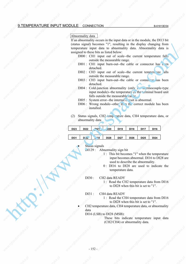
9.TEMPERATURE INPUT MODULE CONNECTION B-61813E/04
- 152 -
Abnormality dataIf an abnormality occurs in the input data or in the module, the DI13 bit (status signal) becomes "1", resulting in the display changing from temperature input data to abnormality data. Abnormality data is assigned to these bits as listed below: DI00 : CH1 input out of scale--the current temperature falls
outside the measurable range. DI01 : CH1 input burn-out--the cable or connector has been
detached. DI02 : CH3 input out of scale--the current temperature falls
outside the measurable range. DI03 : CH3 input burn-out--the cable or connector has been
detached. DI04 : Cold-junction abnormality (only for thermocouple-type
input module)--the temperature of the terminal board unit falls outside the measurable range.
DI05 : System error--the internal circuit is abnormal. DI06 : Wrong module--other than the correct module has been
installed. (2) Status signals, CH2 temperature data, CH4 temperature data, or
abnormality data
DI23 DI22 DI21 DI20 DI19 DI18 DI17 DI16
DI31 DI30 DI29 DI28 DI27 DI26 DI25 DI24
• Status signals DI129 : Abnormality sign bit 1 : This bit becomes "1" when the temperature
input becomes abnormal. DI16 to DI28 are used to describe the abnormality.
0 : DI16 to DI28 are used to indicate the temperature data.
DI30 : CH2 data READY 1 : Read the CH2 temperature data from DI16
to DI28 when this bit is set to "1".
DI31 : CH4 data READY 1 : Read the CH4 temperature data from DI16
to DI28 when this bit is set to "1". • CH2 temperature data, CH4 temperature data, or abnormality
data DI16 (LSB) to DI28 (MSB): These bits indicate temperature input data
(CH2/CH4) or abnormality data.
http://www.cncspares.com/

B-61813E/04 CONNECTION 9.TEMPERATURE INPUT MODULE
- 153 -
Temperature input dataThe temperature input data is in binary. It is ten times the actual temperature. Example (41F3h → 0499 → 49.9°C) The highest three bits are status signals. For a thermoresistance-type module (ATI04A), the DI28 bit is a sign bit. (Negative data is represented in two's complement.) Example (5FFBh → -0.5°C) The highest three bits are status signals. Abnormality dataIf an abnormality occurs in the input data or the module, the DI29 bit (status signal) is set to "1", resulting in the display changing from temperature input data to abnormality data. Abnormality data is assigned to these bits as listed below: DI16 : CH2 input out of scale--the current temperature falls
outside the measurable range. DI17 : CH2 input burn-out--the cable or connector has been
detached. DI18 : CH4 input out of scale--the current temperature falls
outside the measurable range. DI19 : CH4 input burn-out--the cable or connector has been
detached. DI20 : Cold-junction abnormality (only for thermocouple-type
input module)--the temperature of the terminal board unit falls outside the measurable range.
DI21 : System error--the internal circuit is abnormal. DI22 : Wrong module--other than the correct module has been
installed.
http://www.cncspares.com/

9.TEMPERATURE INPUT MODULE CONNECTION B-61813E/04
- 154 -
9.4 COMPLETE CONNECTION OF TEMPERATURE INPUT MODULE
9.4.1 Temperature Input Module Connection Diagram
(There are two types of terminal board units, the first for a thermoresistance-type module and the second for a thermocouple-type module.) See Section 9.7 for explanations about the dimensions of the terminal board.
Temperature sensors •Thermoresistance •J/K thermocouple
Hirose Electric Co., Ltd.
Terminal board unit
Temperature input module
Cable
Hirose Electric Co., Ltd.
http://www.cncspares.com/

B-61813E/04 CONNECTION 9.TEMPERATURE INPUT MODULE
- 155 -
9.4.2 Connector Signal Lists (1) Thermoresistance input module ATI04A
Channel Pin No. Pin No.Channel 1 - 1A 1B Channel 1 + 2A 2B Channel 1 + 3A 3B Channel 2 - 4A 4B Channel 2 + 5A 5B Channel 2 + 6A 6B Channel 3 - 7A 7B Channel 3 + 8A 8B Channel 3 + 9A 9B Channel 4 - 10A 10B Channel 4 + 11A 11B Channel 4 + 12A 12B
Unusable 13A 13B Unusable 14A 14B Unusable 15A 15B Unusable 16A 16B Unusable 17A 17B
(2) Thermocouple input module ATI04B
Channel Pin No. Pin No.Channel 1 - 1A 1B Channel 1 + 2A 2B
Unusable 3A 3B Channel 2 - 4A 4B Channel 2 + 5A 5B
Unusable 6A 6B Channel 3 - 7A 7B Channel 3 + 8A 8B
Unusable 9A 9B Channel 4 - 10A 10B Channel 4 + 11A 11B
Unusable 12A 12B Cold-junction compensation element A 13A 13B Cold-junction compensation element B1 14A 14B Cold-junction compensation element B2 15A 15B
Unusable 16A 16B Unusable 17A 17B
ht
tp://www.cncspares.com/

9.TEMPERATURE INPUT MODULE CONNECTION B-61813E/04
- 156 -
9.4.3 Terminal Board Unit Connection Diagram
NOTE The thermocouple module ATB01B incorporates a
cold-junction compensation device (PT1). It is essential to temperature measurement with a thermocouple. Use the ATB01B whenever the ATI04B is used.
Temperature sensors •Thermoresistance •J/K thermocouple
For thermoresistance-type module (ATB01A)
Terminal board Connector Terminal board
For thermocouple-type module (ATB01B)
Connector
http://www.cncspares.com/

B-61813E/04 CONNECTION 9.TEMPERATURE INPUT MODULE
- 157 -
9.5 TIMING CHARTS (1) 2-channel mode
NOTE The actual response time is the sum of the time
required to pass the filter and the scan time that is determined depending on the system.
(2) 4-channel automatic measurement mode
NOTE The actual response time is the sum of the time
required to pass the filter and the scan time that is determined depending on the system.
(3) 4-channel manual measurement mode
Temperature data
0.3s (Note)
CH1/CH2 data READY
5ms
NC READY
Temperature data
CH1/CH2 data READYCH3/CH4 data READY
Specified period (0.5 to 10 s) (Note)
Channel select
READ request1 s or longer
Temperature data
CH1/CH2 data READYCH3/CH4 data READYht
tp://www.cncspares.com/

9.TEMPERATURE INPUT MODULE CONNECTION B-61813E/04
- 158 -
9.6 MEASUREMENT EXAMPLES (1) 2-channel mode
(a) Flowchart
Specify the module type (DO17). 0 : Thermocouple module 1 : Thermoresistance module
Specify the sensor type (DO18). 0 : Pt/K 1 : JPt/J
Reset the number of channels bit (DO24) to "0".
Set NC READY (DO16) to "1".
When CH2 data READY (DI30 of input signal) becomes "1", input signals DI16 to DI28 represent CH2 data.
START
Now ready to measure.
When CH1 data READY (DI14 of input signal) becomes"1", input signals DI00 to DI12 represent CH1 data.
* Check that NC READY (DO16) and DO19 are "0".
http://www.cncspares.com/

B-61813E/04 CONNECTION 9.TEMPERATURE INPUT MODULE
- 159 -
(b) Ladder example The following measurement and ladder examples apply
when a thermoresistance module with Pt is used for measurement.
PMC measurement
GROUP BASE SLOT NAME GROUP BASE SLOT NAMEX000 0 0 1 /4 Y000 0 0 1 /4 X001 0 0 1 /4 Y001 0 0 1 /4 X002 0 0 1 /4 Y002 0 0 1 /4 X003 0 0 1 /4 Y003 0 0 1 /4
NOTE Set the ladder scan time to 0.25 s or less. This example of ladder use is for the second level. R0.0 is used as a normally open relay.
Ladder
Specify the module. (thermoresistance-type module) Specify the sensor (Pt). Specify the number of channels (two channels). NC READY (When R1.0 becomes "1", NC READY becomes "1" to start measurement.) When CH1 data READY is "1", CH1 temperature data is sent to R010 to R011. When CH2 data READY is "1", CH2 temperature data is sent to R012 to R013.
http://www.cncspares.com/

9.TEMPERATURE INPUT MODULE CONNECTION B-61813E/04
- 160 -
(2) 4-channel automatic measurement mode (a) Flowchart
Specify the module type (DO17). 0 : Thermocouple module 1 : Thermoresistance module
Specify the sensor type (DO18). 0 : Pt/K 1 : JPt/J
Set the number of channels bit (DO24) to "1".
Set NC READY (DO16) to "1".
When CH2 data READY (DI30 of input signal) becomes "1", input signals DI16 to DI28 represent CH2 data.
START
Now ready to measure.
When CH1 data READY (DI14 of input signal) becomes"1", input signals DI00 to DI12 represent CH1 data.
Set the 4-channel mode specification bit (DO25) to "0".
Specify the channel switching period (DO00 to DO15).
When CH3 data READY (DI15 of input signal) becomes"1", input signals DI00 to DI12 represent CH3 data.
When CH4 data READY (DI31 of input signal) becomes"1", input signals DI16 to DI28 represent CH4 data.
* Check that NC READY (DO16) and DO19 are "0".
http://www.cncspares.com/

B-61813E/04 CONNECTION 9.TEMPERATURE INPUT MODULE
- 161 -
(b) Ladder example The following measurement and ladder examples apply
when a J thermocouple module is used for measurement. PMC assignment
GROUP BASE SLOT NAME GROUP BASE SLOT NAME
X000 0 0 1 /4 Y000 0 0 1 /4 X001 0 0 1 /4 Y001 0 0 1 /4 X002 0 0 1 /4 Y002 0 0 1 /4 X003 0 0 1 /4 Y003 0 0 1 /4
NOTE This example of ladder use is for the second level. R0.0 is used as a normally open relay.
Ladder
Specify the module. (thermocouple-type module) Specify the sensor (J thermocouple). Specify the number of channels (four channels). Specify a 4-channel mode (automatic measurement). Specify the channel switching period for 4-channel automatic measurement. Specify 0025 to provide a period of 2.5 s.(Note) NC READY (When R1.0 is set to "1", NC READY becomes "1" to start measurement.) When CH1 data READY is set to "1", CH1 temperature data is sent to R010 to R011.
http://www.cncspares.com/

9.TEMPERATURE INPUT MODULE CONNECTION B-61813E/04
- 162 -
NOTE If your machine is the PMC-N, NA, or QA, specify
6400. 0025 ⇒ 0019h. Because the upper byte is
exchanged with the lower byte, 1900h ⇒ 6400.
When CH2 data READY is "1", CH2 temperature data is sent to R012 to R013. When CH3 data READY is "1", CH3
temperature data is sent to R014 to R015. When CH4 data READY is "1", CH4
temperature data is sent to R016 to R017.
http://www.cncspares.com/

B-61813E/04 CONNECTION 9.TEMPERATURE INPUT MODULE
- 163 -
(3) 4-channel manual measurement mode (a) Flowchart
* Reading CH1 and CH2 data
NOTE After setting NC READY to "1", wait for one second,
and then set the READ request to "1".
Specify the module type (DO17). 0 : Thermocouple module 1 : Thermoresistance module
Specify the sensor type (DO18). 0 : Pt/K 1 : JPt/J
Set the number of channels bit (DO24) to "1".
Set NC READY (DO16) to "1".
START
Now ready tomeasure.
Set the 4-channel mode specification bit (DO25) to "1".
* Check that NC READY (DO16) and DO19 are "0".
Ensure that the READ request bit(DO22) is set to "0".
Reset the channel select bit (DO26) to "0".
When CH2 data READY (DI30 of input signal) becomes "1", input signals DI16 to DI28 represent CH2 data.
When CH1 data READY (DI14 of input signal) is set to "1", input signals DI00 to DI12 represent CH1 data.
Reset the READ request bit (DO22) to "0".
Set the READ request bit (DO22) to "1". (Note)
http://www.cncspares.com/

9.TEMPERATURE INPUT MODULE CONNECTION B-61813E/04
- 164 -
* Reading CH3 and CH4 data
NOTE 1 After setting the NC READY bit to "1", wait for one
second, and then set the READ request bit to "1". 2 To create the ladder for 4-channel manual
measurement, refer to the above flowchart or timing chart.
When CH4 data READY (DI31 of input signal) is set to "1",input signals DI16 to DI28 represent CH4 data.
When CH3 data READY (DI15 of input signal) is set to "1",input signals DI00 to DI12 represent CH3 data.
Ensure that the READ request bit (DO22) is set to "0".
Reset the channel select bit (DO26) to "0".
Set the READ request bit (DO22) to "1".
Reset the READ request bit (DO22) to "0".
(Note)
http://www.cncspares.com/

B-61813E/04 CONNECTION 9.TEMPERATURE INPUT MODULE
- 165 -
9.7 TERMINAL BOARD UNIT DIMENSIONS To use a DIN rail, add its height (tDIN) to the dimension shown below.
(For thermocouple module) (For thermoresistance module)
Unit: mm
Unit: mm
http://www.cncspares.com/

10.OPTICAL I/O Link ADAPTER CONNECTION B-61813E/04
- 166 -
10 OPTICAL I/O Link ADAPTER The signal cable K1X shown in the general connection diagram ( in section 4.1) can be extended to the maximum length of 200 m with optical fiber cables using an optical I/O link adapter. Two optical I/O Link adapters, A13B-0154-B001 and A13B-0154-B002 (high-speed response type).
NOTE 1 For the cable K2X, the optical I/O link adapter
cannot be applied to. 2 In the following cases, make sure to use an optical
fiber cable for K1X. For cabling within the same cabinet, however, this applies only when the cable is 15 m or longer.
• When the cable is more than 10 meters long. • When the cable K1X runs between different
cabinets and it is impossible to connect the cabinets with a wire of 5.5 mm2 or thicker.
• When there is concern that the cable K1X is influenced by strong noise.
For example; When there is a strong electromagnetic noise
source beside the cable K1X such as a welding machine and the like.
When a noise generating cable such as a power cable and the like runs for a long distance in parallel with the cable K1X.
http://www.cncspares.com/

B-61813E/04 CONNECTION 10.OPTICAL I/O Link ADAPTER
- 167 -
10.1 EXTERNAL DIMENSION OF OPTICAL I/O Link
10.2 WEIGHT OF OPTICAL I/O Link Main body: Approx. 100g
Unit: mm
http://www.cncspares.com/

10.OPTICAL I/O Link ADAPTER CONNECTION B-61813E/04
- 168 -
10.3 CONNECTION OF OPTICAL I/O Link (1) Connection diagram (2) Interunit connecting cables K3X 01 SIN 11 0V 02 *SIN 12 0V 03 SOUT 13 0V 04 *SOUT 14 0V 05 15 0V 06 16 0V 07 17 08 18 +5V 09 +5V 19 10 20 +5V
(a) Recommended connector for cable side: PCR-E20FA (manufactured by HONDA TSUSHIN) FI30-20S (manufactured by HIROSE ELECTRIC) FCN-247J020-G/E (manufactured by Fujitsu) 52622-2011 (manufactured by Molex) (b) Recommended cable (with material): A66L-0001-0284#10P (c) Cable length: Max.2m (when the recommended cable is
used)
(3) Optical cable <1> Specification (Be sure to use the optical cable conforming to
this specification.): • A66L-6001-0009 (usable only with the standard type
optical I/O Link adapter) • A66L-6001-0026
<2> Cable length: Max.200m (when the standard type optical I/O Link adapter
A13B-0154-B001 is used) Max.100m (when the high-speed response type optical I/O
Link adapter A13B-0154-B002 is used)
NOTE The cable length stated above applies when the
optical fiber junction adapter A02B-0094-K841 is not in use. See Subsection 10.7.5 for details.
K3X
A66L-6001-0009
A66L-6001-0026K3X
http://www.cncspares.com/

B-61813E/04 CONNECTION 10.OPTICAL I/O Link ADAPTER
- 169 -
10.4 POWER SOURCE OF OPTICAL I/O Link ADAPTER The power source is common to the standard type (A13B-0514-B001) and the high-speed response type (A13B-0154-B002). (1) Power voltage: 4.75 V to 5.25 V (at the receiving end) (2) Consumption current: 200mA (3) Power is supplied via the I/O Link cable K3X.
10.5 INSTALLATION CONDITIONS OF OPTICAL I/O Link ADAPTER
(1) As this adapter is not a closed type, install it in the same closed
type cabinet as used for the NC control unit. (2) Make sure to ground the case using the case fixing screw of the
adapter. (3) As the adapter is light, it is not necessary to fix it with screws.
However, keep it from getting contact with other circuits lest it should be short-circuited. In addition, when fixing the adapter in a cabinet and the like, fix it with a L-type fitting using the case fixing screws (M3) of the adapter.
http://www.cncspares.com/

10.OPTICAL I/O Link ADAPTER CONNECTION B-61813E/04
- 170 -
10.6 CAUTIONS FOR USING OPTICAL I/O Link ADAPTERS
10.6.1 Configuring I/O Links Using Optical I/O Link Adapters The following restriction applies when I/O Links are configured using optical I/O Link adapters. Restriction on the number of optical I/O Link adapters used per I/O Link channel Master - Group#0 - - - - - - - - Group#1 - - - - • • • • • • - - - Group#15 (CNC) ↑ (I/O-A or the like) ↑ (I/O-A or the like) ↑ ↑ (I/O-A or the like) Partition #1 Partition #2 Partition #3 Partition #4 When using the standard-type optical I/O Link adapter (A13B-0154-B001): Up to 5 partitions (I/O Link master -- group #0 -- group #1 -- ... --
group #15) can be configured with optical fibers. Use electrical cables for the K1X in the other partitions. When using the high-speed response type optical I/O Link adapter (A13B-0154-B002): The A13B-0154-B002 performs optical-electrical conversion
faster than the A13B-0154-B001. All (16) partitions (master -- group #0 -- group #1 -- ... -- group
#15) can be configured with optical fiber.
NOTE 1 When using an optical fiber for I/O Links, use optical I/O Link adapters conforming to
the same specification on both ends of the optical fiber. 2 When using the high-speed response type optical I/O Link adapter
(A13B-0154-B002), do not use any optical fiber cable other than the A66L-0001-0026.
When using the standard-type optical I/O Link adapter (A13B-0154-B001), either of the optical fiber cables A66L-0001-0009 and A66L-0001-0026 can be used.
3 If 6 or more partitions of an I/O Link are configured with optical fibers, using the standard-type optical I/O Link adapter even in one of these partitions disables the I/O Link from operating normally.
When using optical fibers in 6 or more partitions, do not use the standard-type optical I/O Link adapter; use only the high-speed response type optical I/O Link adapter.
Parts required per optical I/O Link partition (1) When configuring 5 or fewer partitions with optical fibers Two standard-type optical I/O Link adapters (A13B-0154-B001) Two unit-to-unit connecting cables (K3X) One optical cable (A66L-6001-0026 or A66L-6001-0009) (2) When configuring six or more partitions with optical fibers Two high-speed response type optical I/O Link adapters (A13B-0154-B002) Two unit-to-unit connecting cables (K3X) One optical cable (A66L-6001-0026)
http://www.cncspares.com/

B-61813E/04 CONNECTION 10.OPTICAL I/O Link ADAPTER
- 171 -
10.6.2 When Using Series 16i/18i/21i-MODEL B as Master Two channels' worth of I/O Link signals are allocated to the I/O Link connector (JD44A) of the Series 16i/18i/21i-MODEL B. (1) When using only one I/O Link channel No I/O Link connector adapter (A20B-1007-0680) is required. Either an electrical cable or optical I/O Link can be used as the
K1X. When using the optical I/O Link, make a connection as described in (1) of Section 10.3.
In this connection, the DI/DO data of channel 2 is invalid. (2) When using two I/O Link channels Using two I/O Link channels requires using the I/O Link
connector adapter (A20B-1007-0680). When configuring an optical I/O Link, you can use optical fibers
between the I/O Link connector adapter and group #15 (all partitions on channels 1 and 2). No optical fiber can be used between the CNC (JD44A) and I/O Link connector adapter (JD44B). Use a 1-meter electrical cable (A02B-0236-K848).
NOTE Do not have the cable length from the CNC (JD44A)
to the I/O Link connector adapter and then to the optical I/O Link adapter exceed 2 meters in total.
(Example) Partition #1 on channel 2 configured with optical I/O Link
Optical fiber- A66L-6001-0009 - A66L-6001-0026
Electrical cableSee descriptions about unit-to-unit connecting cables K3X in Section 10.3.
CNC (16i/18i/21i -MODEL B)
JD44A
A20B-1007-0680
JD44B
JD1A-1
JD1A-2
Channel 2
Group#0 I/O Unit, etc
A13B-0154-B001 or A13B-0154-B002
Channel 1
Electrical cable K1X See (1) of Section 4.5.
JD1B
JD1B
A02B-0236-K848 (1m)
Group#0 I/O Unit, etc
Keep the total cable length within 2 meters.
http://www.cncspares.com/

10.OPTICAL I/O Link ADAPTER CONNECTION B-61813E/04
- 172 -
10.6.3 When Using Series 30i/31i/32i-MODEL B as Master Three channels' worth of I/O Link signals are allocated to the I/O Link connector (JD51A) of the Series 30i/31i/32i-MODEL B. (1) When using only one I/O Link channel You do not need to use the I/O Link connector adapter
(A20B-1007-0680) or 3-channel I/O Link connector adapter (A20B-1008-0360).
Either an electrical cable or optical I/O Link can be used as the K1X. When using the optical I/O Link, make a connection as described in (1) of Section 10.3.
In this connection, the DI/DO data for channels 2 and 3 is invalid. (2) When using two I/O Link channels Using two I/O Link channels requires using the I/O Link
connector adapter (A20B-1007-0680). When configuring an optical I/O Link, you can use optical fibers
between the I/O Link connector adapter and group #15 (all partitions on channels 1 and 2). No optical fiber can be used between the CNC (JD51A) and I/O Link connector adapter (JD44B). Use a 1-meter electrical cable (A02B-0236-K848).
NOTE Do not have the cable length from the CNC (JD51A)
to the I/O Link connector adapter and then to the optical I/O Link adapter exceed 2 meters in total.
(Example) Partition #1 on channel 1 configured with optical I/O Link
Optical fiber- A66L-6001-0009 - A66L-6001-0026
Electrical cableSee descriptions about unit-to-unit connecting cables K3X in Section 10.3.
CNC (30i/31i/32i)
JD51A
A20B-1007-0680
JD44B
JD1A-1
JD1A-2
Channel 2
A13B-0154-B001 or A13B-0154-B002
Channel 1
Electrical cable K1X See (1) of Section 4.5.
JD1B
JD1B
A02B-0236-K848(1m)
Group#0 I/O Unit, etc
Group#0 I/O Unit, etc
Keep the total cable length within 2 meters.
ht
tp://www.cncspares.com/
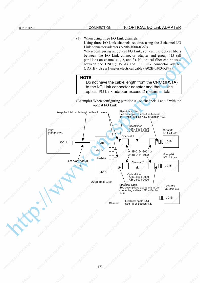
B-61813E/04 CONNECTION 10.OPTICAL I/O Link ADAPTER
- 173 -
(3) When using three I/O Link channels Using three I/O Link channels requires using the 3-channel I/O
Link connector adapter (A20B-1008-0360). When configuring an optical I/O Link, you can use optical fibers
between the I/O Link connector adapter and group #15 (all partitions on channels 1, 2, and 3). No optical fiber can be used between the CNC (JD51A) and I/O Link connector adapter (JD51B). Use a 1-meter electrical cable (A02B-0303-K849).
NOTE Do not have the cable length from the CNC (JD51A)
to the I/O Link connector adapter and then to the optical I/O Link adapter exceed 2 meters in total.
(Example) When configuring partition #1 on channels 1 and 2 with the
optical I/O Link
CNC (30i/31i/32i)
JD51A
A20B-1008-0360
JD51B
JD44A-1
JD44A-2
Channel 1
Channel 2
A13B-0154-B001 or A13B-0154-B002
Optical fiber - A66L-6001-0009 - A66L-6001-0026
JD1B
JD1B
A02B-0303-K849(1m)
JD1A
Optical fiber - A66L-6001-0009 - A66L-6001-0026
Electrical cableSee descriptions about unit-to-unit connecting cables K3X in Section 10.3.
JD1B Electrical cable K1X See (1) of Section 4.5. Channel 3
Group#0 I/O Unit, etc
Group#0 I/O Unit, etc
Group#0 I/O Unit, etc
Keep the total cable length within 2 meters.
Electrical cableSee descriptions about unit-to-unit connecting cables K3X in Section 10.3.
http://www.cncspares.com/

10.OPTICAL I/O Link ADAPTER CONNECTION B-61813E/04
- 174 -
10.7 OPTICAL FIBER CABLE This CNC uses optical cables for connections between the control unit and the I/O Unit. Unlike the conventional power cables, optical fiber cables need special care in installation and handling. No optical fiber cable can be used on movable parts.
10.7.1 External View of Optical Fiber Cable (1) Standard length of an optical fiber cable is 10, 15, 20, 30, 50, 100,
and 200 meters. (2) No machine tool builder is allowed to cut or joint optical fiber
cables. (3) If it needs to relay on cabling, use optical fiber junction adapter.
Up to the relay points are allowed on a transmission line.
Reinforced optical fiber code diameter: 8.4mm Tensile strength: Optical fiber code: 25kg Optical fiber code-connector: 2kg Reinforcing cover: 150kg Bending radious of optical fiber code with reinforcing cover: 50mm
http://www.cncspares.com/

B-61813E/04 CONNECTION 10.OPTICAL I/O Link ADAPTER
- 175 -
10.7.2 Notice of Optical Fiber Cable Handling (1) Even though reinforcing cover used on the optical fiber code has
enough mechanical strength, be sure not to be damaged by heavy materials drop.
(2) Detaching and attaching of optical connector should always be made by touching connector. Optical fiber code should not be touched when replacement.
(3) Optical connector is automatically locked with upper side lock levels after being connected. It is impossible to pull out the connector without releasing the lock levers.
(4) Optical connector cannot be connected oppositely. Be sure the connector direction when connection is done.
(5) Optical connector should be processed as follows before laying of optical fiber cable.
Fix a reinforcing cover to a wire with hook or tension member by a tape.
At laying hook the wire or pull the tension member taking enough care that optical connector does not receive pulling strength.
(6) Reinforcing cover is fixed to cable lamp so that optical fiber cable
could not weigh directly the connecting part of connector. (7) Notice that optical connector's chip is clear. The attached protect cap must be always put on when optical
connector is not used. Remove dirty with a clear tissue or absorbent cotton (cotton with
ethyl alcohol is applicable). No other organic solvent than ethyl alcohol cannot be used.
http://www.cncspares.com/

10.OPTICAL I/O Link ADAPTER CONNECTION B-61813E/04
- 176 -
10.7.3 Optical Fiber Cable Clamping Method When reinforcing cover is fixed at cable clamp with sponge, enough sag at optical fiber code as shown below is necessary so that connecting part of optical should not be weighed directly by optical fiber cable.
Optical fiber cable (Bending radius should be more than 25mm, and the reinforcing sheath portion is 50 mm or longer.)
Optical fiber junction adapter or optical data link module
http://www.cncspares.com/

B-61813E/04 CONNECTION 10.OPTICAL I/O Link ADAPTER
- 177 -
10.7.4 Relay Using an Optical Fiber Junction Adapter
(1) External view of an optical fiber junction adapter
(2) Example of the use of an optical fiber junction adapter
Optical fiber junction adapter
Specification: A02B-0094-K841
NOTE Up to one relay points are permitted. When the high-speed response type optical I/O Link
adapter is used, however, it is impossible to use the optical fiber junction adapter.
(3) Installing the optical fiber junction adapter
The optical fiber junction adapter should be installed within a cabinet, as a rule. If it is impossible to avoid installing it within a cabinet, protect the adapter and the optical cable portions (such as connectors and cords) not covered with reinforcement coating from the outside air by, for example, covering them with packing. ht
tp://www.cncspares.com/

10.OPTICAL I/O Link ADAPTER CONNECTION B-61813E/04
- 178 -
(4) Environmental resistance of the optical fiber junction adapter • The optical fiber junction adapter is not waterproof. Even when
optical cables are attached to both ends of the adapter, there are very small gaps in the linked portions, so water resistance can not be expected.
• When optical cables are attached to both ends of the junction adapter installed in a normal environment (such as within a cabinet), it is unlikely that dust will penetrate between the adapter and optical fiber to the degree that it may hamper normal optical linkage. If one or both ends of the adapter are left open, dust and dirt may accumulate even when the adapter is in a normal environment (such as within a cabinet). The dust and dirt on the adapter ends is likely to hamper normal optical linkage when the optical cables are attached. In such a case, clean the junction adapter and the optical connector using the optical fiber junction adapter cleaning method described below.
• Do not allow cutting fluid to splash over the adapter or those optical cable portions (such as connectors and cords) that are not covered with reinforcement coating. If the inside of the adapter and fiber end surfaces are contaminated with cutting fluid, a malfunction may occur.
(3) Cleaning
If the optical fiber junction adapter, optical-to-electrical conversion module, and optical cable are soiled, clean them according to the following procedures. • Cleaning the optical fiber junction adapter and
optical-to-electrical conversion module First, clean the entire housing by wiping it with a cloth moistened
with, or by washing it in, ethyl alcohol or HCFC141B (alternative CFC; High Shower spray can DS-2168, manufactured by Sun Hayato). Similarly, wash the two sleeves in the adapter or wipe them with a cotton swab or the like.
• Cleaning optical cables For the optical cables, it is important to clean the connectors at
their ends. Any soiling on the optical fiber end surfaces will hamper optical transmission, resulting in a malfunction. Wipe the optical fiber end surfaces (that is, the ferrule end surfaces) thoroughly with a soft, clean cloth (like gauze) moistened with ethyl alcohol or HCFC141B, in the same way as described above. The use of cotton swabs may prove convenient. The fiber end surfaces of low-loss optical cables are lower than the ferrules. To remove any soiling from the fiber end surfaces completely, push the cotton swab or gauze into the depressions all the way through while rotating the ferrule. If the ferrules and optical connectors are contaminated with oily substances, and they may extend over a cleaned fiber end surface when it is attached to the optical-to-electrical conversion module, it is a good idea to wash them before wiping the optical fiber end surfaces, using the procedure stated above.
http://www.cncspares.com/

B-61813E/04 CONNECTION 10.OPTICAL I/O Link ADAPTER
- 179 -
10.7.5 Maximum Transmission Distance by Optical Fiber Junction Cable
Maximum transmission distance by optical fiber junction cable is shown below: The maximum transmission distance varies depending on the number of relay points supported by optical fiber junction adapters. When the high-speed response type optical I/O Link adapter is in use, no optical fiber junction adapter can be used.
Optical I/O Link adapter Relay points Max. trans. distance0 200m Standard type 1 100m (total) 0 100m
High-speed response type 1 Not applicable
http://www.cncspares.com/

11.I/O Link DUMMY UNIT CONNECTION B-61813E/04
- 180 -
11 I/O Link DUMMY UNIT
http://www.cncspares.com/

B-61813E/04 CONNECTION 11.I/O Link DUMMY UNIT
- 181 -
11.1 OVERVIEW If a slave unit (such as the FS0, Power Mate, I/O Unit-MODEL A, or connection unit) is removed from the FANUC I/O Link (Note), the group number for those that followed the removed slave unit changes. So, it becomes necessary to change the PMC assignment. However, connecting a FANUC I/O Link dummy unit in place of the removed slave unit makes it unnecessary to change PMC assignment. This chapter describes the electrical and structural specifications that apply to the FANUC I/O Link dummy unit when it is connected to the FANUC I/O Link. Specification: A13B-0167-B001
NOTE The FANUC I/O Link is a serial interface for
connecting the CNC or cell controller to the I/O Unit-MODEL A, Power Mate, or other units for high-speed transfer of I/O signals (bit data).
11.2 EXTERNAL DIMENSIONS
Mounting hole for 2-M4
Units: mm
Mounting hole for 2-M5
http://www.cncspares.com/

11.I/O Link DUMMY UNIT CONNECTION B-61813E/04
- 182 -
11.3 LED INDICATORS (1) PWR: Lights when the FANUC I/O Link dummy unit is supplied
with power. (2) LINK: Lights when the FANUC I/O Link is performing
communication.
11.4 WEIGHT (1) Main unit: Approximately 120 g
11.5 POWER REQUIREMENTS (1) Supply voltage: 4.75 to 5.25 V (at reception terminal) (2) Required current: 180 mA (maximum) (3) Power dissipation: 0.9 W (4) Supply method: Via the I/O link cable
11.6 INSTALLATION CONDITIONS This unit is not hermetically sealed. So, it must be installed in a cabinet that is hermetically sealed to the same level as that for the NC. The cabinet must be installed in a location where the following environmental requirements are satisfied. (1) Ambient temperature Operating: 0 to 45°C Storage and transportation: -20 to 60°C (2) Humidity Normal: 75% or less (relative) Short-period (within one month): 95% (maximum) (3) Vibration Operating: 0.5 G or less
http://www.cncspares.com/
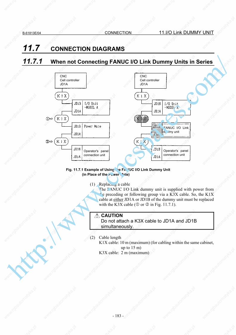
B-61813E/04 CONNECTION 11.I/O Link DUMMY UNIT
- 183 -
11.7 CONNECTION DIAGRAMS
11.7.1 When not Connecting FANUC I/O Link Dummy Units in Series
Fig. 11.7.1 Example of Using the FANUC I/O Link Dummy Unit (in Place of the Power Mate)
(1) Replacing a cable The FANUC I/O Link dummy unit is supplied with power from
the preceding or following group via a K3X cable. So, the K1X cable at either JD1A or JD1B of the dummy unit must be replaced with the K3X cable ( or in Fig. 11.7.1).
CAUTION
Do not attach a K3X cable to JD1A and JD1B simultaneously.
(2) Cable length K1X cable: 10 m (maximum) (for cabling within the same cabinet,
up to 15 m) K3X cable: 2 m (maximum)
CNC Cell controllerJD1A
Operator's panelconnection unit
Operator's panel connection unit
FANUC I/O Link dummy unit
CNC Cell controller JD1A
http://www.cncspares.com/

11.I/O Link DUMMY UNIT CONNECTION B-61813E/04
- 184 -
11.7.2 Connecting FANUC I/O Link Dummy Units in Series
Fig. 11.7.2 (1) Number of FANUC I/O Link dummy units that can be used in
succession Up to two FANUC I/O Link dummy units can be connected via a
K3X cable to a unit that supplies power to them. (See Fig. 11.7.2.) (2) Cable length K1X cable: 10 m (maximum) (for cabling within the same cabinet,
up to 15 m) K3X cable: 2 m (maximum) in total (a + b ≤ 2 m and c + d ≤ 2 m)
11.7.3 Grounding Ground the case of the FANUC I/O Link dummy unit.
Unit with FANUC I/O Link
FANUC I/O Link dummy unit
FANUC I/O Link dummy unit
FANUC I/O Link dummy unit
FANUC I/O Link dummy unit
Unit with FANUC I/O Link
Up to two units Up to two meters
Up to tenmeters
Up to two unitsUp to two meters
http://www.cncspares.com/

B-61813E/04 CONNECTION 11.I/O Link DUMMY UNIT
- 185 -
11.7.4 K3X Cable • Cable connector
Pin ManufacturerSoldering type Crimping type
Housing
Honda Tsushin PCR-E20FS PCR-E20FA PCR-V20LA Hirose Electric FI-40-20S FI-30-20S FI-20-CV2
Fujitsu - FCN-247J020-G/E FCN-240C020-Y/S • Use twisted-pair wires for the SIN, *SIN, SOUT, and *SOUT
signals. • Recommended wires : A66L-0001-0284#10P (twisted-pair wires
with common shielding) • Maximum cable length : 2 m (when recommended wires are used) • Do not connect a wire to an idle pin. • Connect the cable shielding to the grounding plate of the cabinet
via a metal cable clamp at JD1A. (See the applicable CNC or cell controller connection manual.)
CNC, cell controller, AIF01A, etc., or FANUC I/O Link dummy unit
FANUC I/O Link dummy unit, AIF01A, or the like
Connector (see the diagram below.)
http://www.cncspares.com/

12.TWO-CHANNEL I/O Link CONNECTOR ADAPTER CONNECTION B-61813E/04
- 186 -
12 TWO-CHANNEL I/O Link CONNECTOR ADAPTER
http://www.cncspares.com/

B-61813E/04 CONNECTION 12.TWO-CHANNEL I/O Link CONNECTOR ADAPTER
- 187 -
12.1 OVERVIEW The FANUC Series 16i/18i/21i-MODEL B CNC has two FANUC I/O Link interface channels. These channels make it possible to increase the number of I/O points from 1024/1024 to 2048/2048. This chapter explains how to connect a 2-channel I/O Link connector adapter required in using the I/O Link 2-channel function.
NOTE Using this function on the 16i/18i/21i-MODEL B
mentioned above requires specifying the PMC-SB6/-SB7.
This function cannot be used with the PMC on the loader control board.
12.2 CONNECTION FOR USE OF TWO FANUC I/O Link CHANNELS
Two channels' worth of I/O Link signals are allocated to the I/O Link connector (JD44A) of the Series 16i/18i/21i-MODEL B CNC. Three channels' worth of I/O Link signals are allocated to the I/O Link connector (JD51A) of the Series 30i/31i/32i CNC. To use two I/O Link channels in the above CNC, branch out the I/O Link (JD44A/JD51A connector signals), using an I/O Link connector adapter. (See Chapter 13 for explanations about how to use the I/O Link 4-channel function with the Series 30i/31i/32i.)
Connection 2-channel I/O Link connector adapter JD44B
JD1A-1
JD1A-2
CNC unit
JD44A/JD51A
FANUC I/O Link channel 1
FANUC I/O Link channel 2
Connections ahead of the I/O Link connector adapter are the same as for the conventional FANUC I/O Link.
2-channel I/O Link connector adapter: A20B-1007-0680
Restriction When 2 I/O Link channels are used, the FANUC I/O Unit-MODEL B supports connection of up to 8 groups for the 2 channels.
http://www.cncspares.com/

12.TWO-CHANNEL I/O Link CONNECTOR ADAPTER CONNECTION B-61813E/04
- 188 -
12.3 CONNECTING THE CNC WITH TWO-CHANNEL I/O Link CONNECTOR ADAPTER
Connecting the Series 16i/18i/21i-MODEL B CNC
CNC unit JD44A (such as PCR-E20MDK-SL-A)
1 SIN1 11 0V 2 *SIN1 12 0V 3 SOUT1 13 0V 4 *SOUT1 14 0V 5 SIN2 15 0V 6 *SIN2 16 0V 7 SOUT2 17 8 *SOUT2 18 (+5V) 9 (+5V) 19 (+24V) 10 (+24V) 20 (+5V)
2-channel I/O Link connector adapter JD44B (PCR-E20MDT)
1 SIN1 11 0V 2 *SIN1 12 0V 3 SOUT1 13 0V 4 *SOUT1 14 0V 5 SIN2 15 0V 6 *SIN2 16 0V 7 SOUT2 17 8 *SOUT2 18 (+5V) 9 (+5V) 19 10 20 (+5V)
Connecting the Series 30i/31i/32i CNC CNC unit JD51A (such as PCR-E20MDK-SL-A)
1 SIN1 11 0V 2 *SIN1 12 0V 3 SOUT1 13 0V 4 *SOUT1 14 0V 5 SIN2 15 0V 6 *SIN2 16 (*SIN3) 7 SOUT2 17 (SIN3) 8 *SOUT2 18 (+5V) 9 (+5V) 19 (SOUT3)10 (*SOUT3) 20 (+5V)
2-channel I/O Link connector adapter JD44B (PCR-E20MDT)
1 SIN1 11 0V 2 *SIN1 12 0V 3 SOUT1 13 0V 4 *SOUT1 14 0V 5 SIN2 15 0V 6 *SIN2 16 7 SOUT2 17 8 *SOUT2 18 (+5V) 9 (+5V) 19 10 20 (+5V)
The +5-V pin is intended to perform optical fiber transmission using an optical I/O Link adapter. When using no optical I/O Link adapter, keep the +5-V pin unconnected. (See Section 10.6 for details.) When the Series 30i/31i/32i CNC is used, pins 10, 16, 17, and 19 are reserved for I/O Link channel 3. When connecting these CNC units with a 2-channel I/O Link adapter, do not connect anything to these pins. Do not connect anything to the +24-V pin.
http://www.cncspares.com/

B-61813E/04 CONNECTION 12.TWO-CHANNEL I/O Link CONNECTOR ADAPTER
- 189 -
12.4 CABLING
3 4 1 2 7 8 5 6 11 12 13 14 15 16 18 20 9
1234567811121314151618209
CNC unit JD44A,JD51A
SIN1*SIN1
SOUT1*SOUT1
SIN2*SIN2
SOUT2*SOUT2
0V0V0V0V0V
(*2) [0V](*1) (+5V)(*1) (+5V)(*1) (+5V)
I/O Link connector adapter JD44B SOUT1 *SOUT1 SIN1 *SIN1 SOUT2 *SOUT2 SIN2 *SIN2 0V 0V 0V 0V 0V [0V] (*2) (+5V) (*1) (+5V) (*1) (+5V) (*1)
Shield
*1 When using no optical I/O Link adapter, do not connect anything to the +5-V pin.*2 If the CNC of interest is the Series 30i/31i/32i, do not connect anything to pin 16.
Recommended cable-end connector: PCR-E20FA (manufactured by HONDA TSUSHIN) FCN-247J020-G/E (manufactured by Fujitsu) 52622-2011 (manufactured by Molex) Recommended cable (wire): A66L-0001-0284#10P
12.5 CONNECTING TWO-CHANNEL I/O Link CONNECTOR ADAPTER TO I/O Units FOR THE FANUC I/O Link
The 2-channel I/O Link connector adapter can be connected to diverse I/O Units in the same manner as for the conventional FANUC I/O Link.
http://www.cncspares.com/

12.TWO-CHANNEL I/O Link CONNECTOR ADAPTER CONNECTION B-61813E/04
- 190 -
12.6 CABLE LENGTH
LB1
LA
CNC unit
JD44A/JD51A
2-channel I/O Link connector adapter JD44B
JD1A-1
JD1A-2
I/O Unit JD1B
LB2
The sum (LA + LB) of the cable length LA between the CNC unit (JD44A) and 2-channel I/O Link connector adapter (JD44B) and the cable length LB (= LB1 + LB2) between the I/O Link connector adapter (JD1A-1 or JD1A-2) and I/O Unit (JD1B) shall not be longer than 10 m. For cabling within the same cabinet, the sum can be up to 15 m.
12.7 INSTALLING TWO-CHANNEL I/O Link CONNECTOR ADAPTER
Install the 2-channel I/O Link connector adapter in a cabinet that can be sealed on the same level as for the CNC unit.
http://www.cncspares.com/

B-61813E/04 CONNECTION 12.TWO-CHANNEL I/O Link CONNECTOR ADAPTER
- 191 -
12.8 OUTSIDE DIMENSIONS OF TWO-CHANNEL I/O Link CONNECTOR ADAPTER
60
Unit : mm Weight : 60g
JD1A-1 JD44B JD1A-2
45
81
5.1
4.1
23 34
4.5
Allow a space of about 10 cm above the adapter so that cables can be laid and connected.
http://www.cncspares.com/

12.TWO-CHANNEL I/O Link CONNECTOR ADAPTER CONNECTION B-61813E/04
- 192 -
12.9 MOUNTING TWO-CHANNEL I/O Link CONNECTOR ADAPTER
Mounting on the DIN rail
25
35
Unit: mm
Recommended DIN rail
Using screws
11.6
70 2-M4
Unit: mm
Mounting hole dimension and layout diagram
http://www.cncspares.com/

B-61813E/04 CONNECTION 13.THREE-CHANNEL I/O Link CONNECTOR ADAPTER
- 193 -
13 THREE-CHANNEL I/O Link CONNECTOR ADAPTER
http://www.cncspares.com/

13.THREE-CHANNEL I/O Link CONNECTOR ADAPTER CONNECTION B-61813E/04
- 194 -
13.1 OVERVIEW With the FANUC Series 30i/31i/32i CNC, it is possible to use up to 4 FANUC I/O Link interface channels. These channels make it possible to increase the number of I/O points from 1024/1024 to 4096/4096. This chapter explains how to connect a 3-channel I/O Link connector adapter required in using the FANUC I/O Link 4-channel function.
13.2 CONNECTION FOR USE OF FOUR FANUC I/O Link CHANNELS
Three channels' worth of I/O Link signals are allocated to the I/O Link connector (JD51A) of the Series 30i/31i/32i CNC. To use the I/O Link 4-channel function, branch out the JD51A connector signals, using a 3-channel I/O Link connector adapter. (Channel 4 is allocated on the optional board.)
Connection 3-channel I/O Link connector adapter
JD51B JD44A-1
JD44A-2
JD1A
CNC unit
JD51A
FANUC I/O Link channel 2 and channel 3 FANUC I/O Link channel 3
Connections ahead of the 3-channel I/O Link connector adapter are the same as for the conventional FANUC I/O Link.
FANUC I/O Link channel 1 and channel 2
3-channel I/O Link connector adapter: A20B-1008-0360
Restriction The FANUC I/O Unit-MODEL B supports connection of up to 8 groups for the 4 channels.
http://www.cncspares.com/

B-61813E/04 CONNECTION 13.THREE-CHANNEL I/O Link CONNECTOR ADAPTER
- 195 -
13.3 CONNECTING THE CNC WITH THREE-CHANNEL I/O Link CONNECTOR ADAPTER
CNC unit JD51A (such as PCR-E20MDK-SL-A)
1 SIN1 11 0V 2 *SIN1 12 0V 3 SOUT1 13 0V 4 *SOUT1 14 0V 5 SIN2 15 0V 6 *SIN2 16 *SIN3 7 SOUT2 17 SIN3 8 *SOUT2 18 (+5V) 9 (+5V) 19 SOUT3 10 *SOUT3 20 (+5V)
3-channel I/O Link connector adapter JD51B (PCR-E20MDT)
1 SIN1 11 0V 2 *SIN1 12 0V 3 SOUT1 13 0V 4 *SOUT1 14 0V 5 SIN2 15 0V 6 *SIN2 16 *SIN3 7 SOUT2 17 SIN3 8 *SOUT2 18 (+5V) 9 (+5V) 19 SOUT3 10 *SOUT3 20 (+5V)
The +5-V pin is intended to perform optical fiber transmission using an optical I/O Link adapter. When using no optical I/O Link adapter, keep the +5-V pin unconnected.
13.4 CABLING
3 4 1 2 7 8 5 6 19 10 17 16 11 12
12345678171619101112
CNC unit JD51A
SIN1*SIN1
SOUT1*SOUT1
SIN2*SIN2
SOUT2*SOUT2
SIN3*SIN3
SOUT3*SOUT3
0V0V0V0V0V
(+5V)(+5V)(+5V)
3-channel I/O Link connector adapter JD51B SOUT1 *SOUT1 SIN1 *SIN1 SOUT2 *SOUT2 SIN2 *SIN2 SOUT3 *SOUT3 SIN3 *SIN3 0V 0V 0V 0V 0V (+5V) (+5V) (+5V)
13 14
1314
15 15
Shield (*) When using no optical I/O Link adapter, do not connect anything to the +5-V pin.
9 18
918
20 20
Recommended cable-end connector: PCR-E20FA (manufactured by HONDA TSUSHIN) FCN-247J020-G/E (manufactured by Fujitsu) 52622-2011 (manufactured by Molex) Recommended cable (wire): A66L-0001-0284#10P
http://www.cncspares.com/

13.THREE-CHANNEL I/O Link CONNECTOR ADAPTER CONNECTION B-61813E/04
- 196 -
13.5 ALLOCATING THREE-CHANNEL I/O Link CONNECTOR ADAPTER SIGNALS
3-channel I/O Link connector
adapter JD44A-1 (PCR-E20MDT)
1 SIN1 11 0V 2 *SIN1 12 0V 3 SOUT1 13 0V 4 *SOUT1 14 0V 5 SIN2 15 0V 6 *SIN2 16 0V 7 SOUT2 17 8 *SOUT2 18 (+5V) 9 (+5V) 19 10 20 (+5V)
JD44A-2 (PCR-E20MDT)
1 SIN2 11 0V 2 *SIN2 12 0V 3 SOUT2 13 0V 4 *SOUT2 14 0V 5 SIN3 15 0V 6 *SIN3 16 0V 7 SOUT3 17 8 *SOUT3 18 (+5V) 9 (+5V) 19 10 20 (+5V)
JD1A (PCR-E20MDT)
1 SIN3 11 0V 2 *SIN3 12 0V 3 SOUT3 13 0V 4 *SOUT3 14 0V 5 15 0V 6 16 0V 7 17 8 18 (+5V) 9 (+5V) 19 10 20 (+5V)
http://www.cncspares.com/

B-61813E/04 CONNECTION 13.THREE-CHANNEL I/O Link CONNECTOR ADAPTER
- 197 -
13.6 CONNECTING THREE-CHANNEL I/O Link CONNECTOR ADAPTER SIGNAL TO EACH CHANNEL
The 3-channel I/O Link connector adapter can be connected to each I/O Unit in the same manner as for the conventional I/O Link. However, note the following points: The signals for I/O Link channels 1 and 2 are allocated to the JD44A-1 connector. The signals for I/O Link channels 2 and 3 are allocated to the JD44A-2 connector. The JD1A connector is dedicated to I/O Link channel 3. (1) To branch out the 3-channel signals, an ordinary I/O Link cable is
connected to each of the JD44A-1, JD44A-2, and JD1A. In this case, the JD44A-1, JD44A-2, and JD1A correspond, respectively, to channels 1, 2, and 3.
(2) To extend channels 1 and 2 together, the I/O Link connector
adapter (A20B-1007-0680) is connected to the JD44A-1 to separate channels 1 and 2 from each other after the adapter.
To use channel 3, connect it to the JD1A; the JD44A-2 cannot be used.
(3) To extend channels 2 and 3 together, the I/O Link connector
adapter (A20B-1007-0680) is connected to the JD44A-2 to separate channels 2 and 3 from each other after the adapter.
To use channel 1, connect it to the JD44A-1; the JD1A cannot be used.
(1) When branching out the 3-channel signals
CNC
JD51A
3-channel I/O Link connector adapter JD51B JD44A-1 JD44A-2 JD1A
Channel 1
Channel 2
Channel 3
ht
tp://www.cncspares.com/

13.THREE-CHANNEL I/O Link CONNECTOR ADAPTER CONNECTION B-61813E/04
- 198 -
(2) When extending channels 1 and 2 together
CNC
JD51A
3-channel I/O Link connector adapter JD51B JD44A-1 JD44A-2 JD1A Channel 3
I/O Link connector adapter (A20B-1007-0680)
JD44B JD1A-1 JD1A-2
Channel 1
Channel 2
Unusable
(3) When extending channels 2 and 3 together
CNC
JD51A
3-channel I/O Link connector adapter JD51B JD44A-1 JD44A-2 JD1A
Channel 1 I/O Link connector adapter (A20B-1007-0680) JD44B JD1A-1 JD1A-2
Channel 2
Channel 3Unusable
http://www.cncspares.com/

B-61813E/04 CONNECTION 13.THREE-CHANNEL I/O Link CONNECTOR ADAPTER
- 199 -
13.7 CONNECTING THREE-CHANNEL I/O Link CONNECTOR ADAPTER TO TWO-CHANNEL I/O Link CONNECTOR ADAPTER
3-channel I/O Link connector adapter JD44A-1/ JD44A-2 (such as PCR-E20MDK-SL-A)
1 SIN1 11 0V 2 *SIN1 12 0V 3 SOUT1 13 0V 4 *SOUT1 14 0V 5 SIN2 15 0V 6 *SIN2 16 7 SOUT2 17 8 *SOUT2 18 (+5V) 9 (+5V) 19 10 20 (+5V)
2-channel I/O Link connector adapter JD44B (PCR-E20MDT)
1 SIN1 11 0V 2 *SIN1 12 0V 3 SOUT1 13 0V 4 *SOUT1 14 0V 5 SIN2 15 0V 6 *SIN2 16 7 SOUT2 17 8 *SOUT2 18 (+5V) 9 (+5V) 19 10 20 (+5V)
The +5-V pin is intended to perform optical fiber transmission using an optical I/O Link adapter. When using no optical I/O Link adapter, keep the +5-V pin unconnected.
Cabling 3-channel I/O Link connector adapter JD44A-1
SIN1*SIN1
SOUT1*SOUT1
SIN2*SIN2
SOUT2*SOUT2
0V0V0V0V0V
(+5V)(+5V)(+5V)
2-channel I/O Link connector adapter JD44B SOUT1 *SOUT1 SIN1 *SIN1 SOUT2 *SOUT2 SIN2 *SIN2 0V 0V 0V 0V 0V (+5V) (+5V) (+5V)
15 15
(*) When using no optical I/O Link adapter, do not connect anything to the +5-V pin.
3 4 1 2 7 8 5 6 11 12
123456781112
13 14
1314
Shield
9 18
918
20 20
Recommended cable-end connector: PCR-E20FA (manufactured by HONDA TSUSHIN) FCN-247J020-G/E (manufactured by Fujitsu) 52622-2011 (manufactured by Molex) Recommended cable (wire): A66L-0001-0284#10P
http://www.cncspares.com/

13.THREE-CHANNEL I/O Link CONNECTOR ADAPTER CONNECTION B-61813E/04
- 200 -
13.8 CONNECTING THREE-CHANNEL I/O Link CONNECTOR ADAPTER TO I/O Units FOR THE FANUC I/O Link
The 3-channel I/O Link connector adapter can be connected to diverse I/O Units in the same manner as for the conventional FANUC I/O Link.
13.9 CABLE LENGTH
CNC unit
JD51A
LA
3-channel I/O Link connector adapter JD51B JD44A-1
JD44A-2
JD1A
I/O Unit
JD1B
LB1
LB2
LB3
The sum (LA + LB) of the cable length LA between the CNC unit (JD51A) and I/O Link connector adapter (JD51B) and the cable length LB (=LB1+LB2+LB3) between the I/O Link connector adapter (JD44A-1, JD44A-2, or JD1A) and I/O Unit (JD1B) shall not be longer than 10 m. For cabling within the same cabinet, the sum can be up to 15 m.
13.10 INSTALLING THREE-CHANNEL I/O Link CONNECTOR ADAPTER
Install the 3-channel I/O Link connector adapter in a cabinet that can be sealed on the same level as for the CNC unit.
http://www.cncspares.com/

B-61813E/04 CONNECTION 13.THREE-CHANNEL I/O Link CONNECTOR ADAPTER
- 201 -
13.11 OUTSIDE DIMENSIONS OF THREE-CHANNEL I/O Link CONNECTOR ADAPTER
Unit: mm Weight: 90g
JD44A-2JD44A-1 JD1A
80
45
101
JD51B
5.1
4.1
23 34
4.5
Allow a space of about 10 cm above the adapter so that cables can be laid and connected.
http://www.cncspares.com/

13.THREE-CHANNEL I/O Link CONNECTOR ADAPTER CONNECTION B-61813E/04
- 202 -
13.12 MOUNTING THREE-CHANNEL I/O Link CONNECTOR ADAPTER
Mounting on the DIN rail
25
35
Unit: mm
Recommended DIN rail
Using screws
11.6
90 2-M4
Unit: mm
Mounting hole dimension and layout diagram
http://www.cncspares.com/

B-61813E/04 CONNECTION 14.SAFETY FOR USING AC
- 203 -
14 SAFETY FOR USING AC IF AC output module or AC input module is used, Section 14.1 is recommended for safety. When using it for a machine directed to the European market, carefully observe the descriptions in Section 14.1 [as per EN50178].
http://www.cncspares.com/

14.SAFETY FOR USING AC CONNECTION B-61813E/04
- 204 -
14.1 ENVIRONMENT FOR INSTALLATION
14.1.1 Installation Category (Overvoltage Category) Install the unit in the environment of Installation Category II (Overvoltage Category II) or better. [DIN VDE0110] The available impulse surge level to the ground that appears in the power source is 2.5kV maximum. (100VAC system power source is needed in AC input module According to the standard, the available impulse surge level to the ground is 1.5kV for this power source (voltage of which is 150VAC or less). However, for this module, the available impulse surge level to the ground that appears in the power source is 2.5 kV.) Generally, an isolation transformer used for the main power source is regarded as an effective surge filter. The class of the 16-point relay output module (AOR16G) is set to installation category (overvoltage category) I. (Keep any impulse voltage to ground that may appear on the AC power to within 1.5 kV.) The class for the 8-point relay output module (AOR08G), AC output module, and AC input module is set to installation category (overvoltage category) II.
14.1.2 Pollution Degree Install the unit in the environment of pollution degree 2 or better. [EN50178] In cabinet of IP-54 or better (described in Section 3.1), it can be considered as pollution degree 2 or better usually. The IP degree required is depended on the circumstances of machine tool, so select the adequate degree in accordance with such environment.
http://www.cncspares.com/

II. MAINTENANCE
http://www.cncspares.com/

http://www.cncspares.com/

B-61813E/04 MAINTENANCE 1.OVERVIEW
- 207 -
1 OVERVIEW
http://www.cncspares.com/

1.OVERVIEW MAINTENANCE B-61813E/04
- 208 -
1.1 SYSTEM CONFIGURATION I/O Unit-A is connected to a CNC and cell controller through a high-speed serial interface, I/O Link.
(*1) Operator’s panel connection unit
(1) The I/O Link consists of a master and slaves. Master: Series0-C, Series15/16/18/20/21,
Series15i/16i/18i/20i/21i/30i/31i/32i/0i, Power Mate-D/H, Power Mate i-D/H, F-D Mate
Slave: I/O Unit-A, I/O Unit-B, Power Mate, operator's panel connection unit, and Series 0-C, and so on
(2) One I/O Link can connect to up 16 groups of slaves. If the master
is not a CNC, one slave group can contain up to 2 of I/O Unit A (2 base units). If the master is the F-D Mate, however, one group can contain up to 4 I/O Units.
http://www.cncspares.com/

B-61813E/04 MAINTENANCE 1.OVERVIEW
- 209 -
1.2 I/O Unit-A CONFIGURATION An I/O Unit-A consists of a base unit, interface module, and I/O modules. Interface module (AIF01A , AIF01B, or AIF02C) Interface module
(AIF01A, AIF01A2, AIF01B, or AIF02C)
I/O modules
Base unit (ABU05A, ABU10A, ABU05B, or ABU10A)
http://www.cncspares.com/

1.OVERVIEW MAINTENANCE B-61813E/04
- 210 -
1.3 BLOCK DIAGRAM
http://www.cncspares.com/

B-61813E/04 MAINTENANCE 1.OVERVIEW
- 211 -
1.4 I/O Unit-MODEL A CONFORMING TO UL/C-UL The units conforming to the UL/C-UL standard have different drawing numbers. The following table lists the units conforming to the UL/C-UL standard and those not.
I/O Unit-MODEL A conforming to the UL/C-UL standard
I/O Unit-MODEL A not conforming to the UL/C-UL standard
Unit drawing number A03B-0819-Jxxx A03B-0807-Jxxx
Unit specification (interface,
dimensions, and weight)
Same specification
Plastic case Fire retardancy: 94V-0 (material less likely to
burn) Fire retardancy: 94HB
Unit nameplate The nameplates for the base unit and interface module bear a UL mark.
The nameplates have no UL mark.
• Refer to Section 1.5, "LIST OF UNITS", in Part II for individual
unit drawings. • It is possible to use units conforming to the UL/C-UL standard and
those not conforming together.
http://www.cncspares.com/

1.OVERVIEW MAINTENANCE B-61813E/04
- 212 -
1.5 LIST OF UNITS
1.5.1 Units Conforming to UL/C-UL Standard: Ordering Information A03B-0819-Jxxx
Unit conforming to UL/C-UL standard
Name Ordering information
Unit drawing number
Drawing number for printed circuit board in unit
Horizontal type ABU10A A03B-0819-J001 A03B-0819-C001 A20B-9001-0040 10 slots Vertical type ABU10B A03B-0819-J004 A03B-0819-C004 A20B-2003-0100 Horizontal type ABU05A A03B-0819-J002 A03B-0819-C002 A20B-9001-0020
Base unit
5 slots Vertical type ABU05B A03B-0819-J003 A03B-0819-C003 A20B-2000-0510 Power supply connector: SORIAU JAPAN 3-pin (former Burndy)
AIF01A A03B-0819-J011 A03B-0819-C011 A20B-8000-0410
Power supply connector: Tyco Electronics 3-pin
AIF01A2 A03B-0819-J014 A03B-0819-C014 A20B-8000-0411
Power supply connector: SORIAU JAPAN 3-pin (former Burndy)
AIF01B A03B-0819-J012 A03B-0819-C012 A20B-8000-0420
Interface module
Power supply connector: SORIAU JAPAN 3-pin (former Burndy)
AIF02C A03B-0819-J013 A03B-0819-C013 A20B-8000-0710
32 points, 20ms, HONDA 50-pin
AID32A1 A03B-0819-J101 A03B-0819-C101 A20B-8002-0450 or -9000-0970
32 points, 2ms, HONDA 50-pin
AID32B1 A03B-0819-J102 A03B-0819-C102 A20B-8002-0451 or -9000-0971
Non-insulations
32 points, 20 ms and 2 ms intermixed, HONDA 50-pin
AID32H1 A03B-0819-J111 A03B-0819-C111 A20B-8002-0452 or -9000-0972
16 points, NEG, 20ms, terminal block
AID16C A03B-0819-J103 A03B-0819-C103 A20B-8002-0380 or -9000-0931
16 points, NEG, 2ms, terminal block
AID16K A03B-0819-J113 A03B-0819-C113 A20B-8002-0381 or -9000-0932
16 points, POS, 20ms, terminal block
AID16D A03B-0819-J104 A03B-0819-C104 A20B-8002-0370 or -9000-0901
16 points, POS, 2ms, terminal block
AID16L A03B-0819-J114 A03B-0819-C114 A20B-8002-0371 or -9000-0902
32 points, 20ms, HONDA 50-pin
AID32E1 A03B-0819-J105 A03B-0819-C105 A20B-8002-0150
32 points, 20ms, HIROSE 50-pin
AID32E2 A03B-0819-J110 A03B-0819-C110 A20B-8002-0160
32 points, 2ms, HONDA 50-pin
AID32F1 A03B-0819-J106 A03B-0819-C106 A20B-8002-0151
DC input module
Insulations
32 points, 2ms, HIROSE 50-pin
AID32F2 A03B-0819-J109 A03B-0819-C109 A20B-8002-0161
AC input module 16 points, 100 to 115VAC terminal block
AIA16G A03B-0819-J107 A03B-0819-C107 A20B-8000-0341 http://www.cncspares.com/

B-61813E/04 MAINTENANCE 1.OVERVIEW
- 213 -
Unit conforming to UL/C-UL standard
Name Ordering information
Unit drawing number
Drawing number for printed circuit board in unit
Non-insulations
32 points, NEG, 0.3A HONDA 50-pin
AOD32A1 A03B-0819-J162 A03B-0819-C162 A20B-8002-0460 or -9001-0110
8 points, NEG, 2A, terminal block
AOD08C A03B-0819-J151 A03B-0819-C151 A20B-8002-0420 or -9001-0210
8 points, POS, 2A, terminal block
AOD08D A03B-0819-J152 A03B-0819-C152 A20B-8002-0410 or -9001-0220
8 points, POS, 2A, output protection, terminal block
AOD08DP A03B-0819-J183 A03B-0819-C183 A20B-8002-0060
16 points, NEG, 0.5A, terminal block
AOD16C A03B-0819-J153 A03B-0819-C153 A20B-8002-0400 or -9000-0941
16 points, POS, 0.5A, terminal block
AOD16D A03B-0819-J154 A03B-0819-C154 A20B-8002-0390 or -9000-0921
16 points, POS, 2A HONDA 40-pin
AOD16D2 A03B-0819-J171 A03B-0819-C171 A20B-8002-0570
16 points, POS, 2A Weidmüller 24-pin connector
AOD16D3 A03B-0819-J185 A03B-0819-C185 A20B-8002-0520
16 points, POS, 0.3A, output protection, terminal block
AOD16DP A03B-0819-J182 A03B-0819-C182 A20B-8002-0070
32 points, NEG, 0.3A HONDA 50-pin connector
AOD32C1 A03B-0819-J155 A03B-0819-C155 A20B-8002-0430 or -9001-0070
32 points, NEG, 0.3A HIROSE 50-pin connector
AOD32C2 A03B-0819-J172 A03B-0819-C172 A20B-8002-0440 or -9001-0530
32 points, POS, 0.3A HONDA 50-pin connector
AOD32D1 A03B-0819-J156 A03B-0819-C156 A20B-8000-0440
DC output module
Insulations
32 points, POS, 0.3A HIROSE 50-pin connector
AOD32D2 A03B-0819-J167 A03B-0819-C167 A20B-8000-0510
5 points, 2A, 100 to 230VACterminal block
AOA05E A03B-0819-J157 A03B-0819-C157 A20B-8000-0470
8 points, 1A, 100 to 230VACterminal block
AOA08E A03B-0819-J158 A03B-0819-C158 A20B-8000-0480
AC output module
12 points, 0.5A, 100 to 115VAC, terminal block
AOA12F A03B-0819-J159 A03B-0819-C159 A20B-8000-0321
8 points, 4A, terminal block AOR08G A03B-0819-J160 A03B-0819-C160 A20B-8002-0470 or -9001-0200
16 points, 2A, terminal block AOR16G A03B-0819-J161 A03B-0819-C161 A20B-8000-0101
Relay output module
16 points, 2A, HIROSE 50-pin AOR16H2 A03B-0819-J165 A03B-0819-C165 A20B-8000-0500 DC input/output hybrid module
DI: 24 points DO: 16 points, NEG HONDA 50-pin
AIO40A A03B-0819-J200 A03B-0819-C200 A20B-9001-0240
12bit, terminal block AAD04A A03B-0819-J051 A03B-0819-C051 A20B-8000-0450 Analog input module 16bit, terminal block AAD04B A03B-0819-J063 A03B-0819-C063 A20B-8002-0590 12bit, terminal block ADA02A A03B-0819-J052 A03B-0819-C052 A20B-8000-0460 Analog output module 14bit, terminal block ADA02B A03B-0819-J060 A03B-0819-C060 A20B-8001-0980
High-speed counter module ACT01A A03B-0819-J053 A03B-0819-C053 A20B-8000-0540 Pt/JPt ATI04A A03B-0819-J056 A03B-0819-C056 A74L-0001-0083#PTJ/K ATI04B A03B-0819-J057 A03B-0819-C057 A74L-0001-0083#JKPt/JPt ATB01A A03B-0819-J350 A03B-0819-C350 A20B-1005-0920
Temperature input module
J/K ATB01B A03B-0819-J351 A03B-0819-C351 A20B-1005-0930
http://www.cncspares.com/

1.OVERVIEW MAINTENANCE B-61813E/04
- 214 -
1.5.2 Other Units (not Conforming to UL/C-UL)
Name Ordering
information Drawing number for printed circuit
Optical I/O Link adapter A13B-0154-B001 A20B-1004-0240 High-speed response type optical I/O Link adapter
A13B-0154-B002 A20B-1004-0241
Optical fiber junction adapter A02B-0094-K841 - I/O Link dummy unit A13B-0167-B001 A20B-8000-0940 2-channel I/O Link connector adapter A20B-1007-0680 A20B-1007-0680 3-channel I/O Link connector adapter A20B-1008-0360 A20B-1008-0360
1.5.3 Early Units (Units not Conforming to UL/C-UL: Ordering
Information A03B-0807-Jxxx) The modules listed below are those produced before the factory was UL-approved. The module's basic performance does not differ between A03B-0807-Jxxx and A03B-0819-Jxxx. The units with the new ordering information A03B-0819-Jxxx are housed in cases made of material less likely to burn.
Early unit
Name Early ordering information
Early-unit drawing number
Drawing number for printed circuit board in early unit
Horizontal type ABU10A A03B-0807-J001 A03B-0807-C001 A20B-9001-0040 10 slots Vertical type ABU10B A03B-0807-J004 A03B-0807-C004 A20B-2003-0100
or -2000-0550 Horizontal type ABU05A A03B-0807-J002 A03B-0807-C002 A20B-9001-0020
Base unit
5 slots Vertical type ABU05B A03B-0807-J003 A03B-0807-C003 A20B-2000-0510
AIF01A A03B-0807-J011 A03B-0807-C011 A20B-8000-0410 AIF01B A03B-0807-J012 A03B-0807-C012 A20B-8000-0420
Interface module
AIF02C A03B-0807-J013 A03B-0807-C013 A20B-8000-0710 32 points, 20ms, HONDA 50-pin
AID32A1 A03B-0807-J101 A03B-0807-C101 A20B-9000-0970
32 points, 2ms, HONDA 50-pin
AID32B1 A03B-0807-J102 A03B-0807-C102 A20B-9000-0971
Non-insulations
32 points, 20 ms and 2 ms intermixed, HONDA 50-pin
AID32H1 A03B-0807-J111 A03B-0807-C111 A20B-9000-0972
16 points, NEG, 20ms, terminal block
AID16C A03B-0807-J103 A03B-0807-C103 A20B-9000-0931
16 points, NEG, 2ms, terminal block
AID16K A03B-0807-J113 A03B-0807-C113 A20B-9000-0932
16 points, POS, 20ms, terminal block
AID16D A03B-0807-J104 A03B-0807-C104 A20B-9000-0901
16 points, POS, 2ms, terminal block
AID16L A03B-0807-J114 A03B-0807-C114 A20B-9000-0902
32 points, 20ms, HONDA 50-pin
AID32E1 A03B-0807-J105 A03B-0807-C105 A20B-8002-0150 or -9001-0010
32 points, 20ms, HIROSE 50-pin
AID32E2 A03B-0807-J110 A03B-0807-C110 A20B-8002-0160 or -9001-0280
32 points, 2ms, HONDA 50-pin
AID32F1 A03B-0807-J106 A03B-0807-C106 A20B-8002-0151 or -9001-0011
DC input module
Insulations
32 points, 2ms, HIROSE 50-pin
AID32F2 A03B-0807-J109 A03B-0807-C109 A20B-8002-0161 or -9001-0281
AC input module 16 points, 100 to 115VAC terminal block
AIA16G A03B-0807-J107 A03B-0807-C107 A20B-8000-0341
http://www.cncspares.com/

B-61813E/04 MAINTENANCE 1.OVERVIEW
- 215 -
Early unit
Name Early ordering information
Early-unit drawing number
Drawing number for printed circuit board in early unit
Non-insulations 32 points, NEG, 0.3A, HONDA 50-pin
AOD32A1 A03B-0807-J162 A03B-0807-C162 A20B-9001-0110
8 points, NEG, 2A, terminal block
AOD08C A03B-0807-J151 A03B-0807-C151 A20B-9001-0210 or -9000-0951
8 points, POS, 2A, terminal block
AOD08D A03B-0807-J152 A03B-0807-C152 A20B-9001-0220 or -9000-0911
16 points, NEG, 0.5A, terminal block
AOD16C A03B-0807-J153 A03B-0807-C153 A20B-9000-0941
16 points, POS, 0.5A, terminal block
AOD16D A03B-0807-J154 A03B-0807-C154 A20B-9000-0921
16 points, POS, 2A, HIROSE 40-pin
AOD16D2 A03B-0807-J171 A03B-0807-C171 A20B-8002-0570 or -9001-0490
16 points, POS, 0.3A, output protection, terminal block
AOD16DP A03B-0807-J182 A03B-0807-C182 A20B-8002-0070
32 points, NEG, 0.3A, HONDA 50-pin
AOD32C1 A03B-0807-J155 A03B-0807-C155 A20B-9001-0070
32 points, NEG, 0.3A, HIROSE 50-pin
AOD32C2 A03B-0807-J172 A03B-0807-C172 A20B-9001-0530
32 points, POS, 0.3A, HONDA 50-pin
AOD32D1 A03B-0807-J156 A03B-0807-C156 A20B-8000-0440
DC output module
Insulations
32 points, POS, 0.3A, HIROSE 50-pin
AOD32D2 A03B-0807-J167 A03B-0807-C167 A20B-8000-0510
5 points, 2A, 100 to 230VACterminal block
AOA05E A03B-0807-J157 A03B-0807-C157 A20B-8000-0470 or -8000-0251
8 points, 1A, 100 to 230VACterminal block
AOA08E A03B-0807-J158 A03B-0807-C158 A20B-8000-0480 or -8000-0381
AC output module
12 points, 0.5A, 100 to 115VAC terminal block
AOA12F A03B-0807-J159 A03B-0807-C159 A20B-8000-0321
8 points, 4A, terminal block AOR08G A03B-0807-J160 A03B-0807-C160 A20B-9001-0200 or -9000-0961
16 points, 2A, terminal block AOR16G A03B-0807-J161 A03B-0807-C161 A20B-8000-0101
Relay output module
16 points, 2A, HIROSE 50-pin
AOR16H2 A03B-0807-J165 A03B-0807-C165 A20B-8000-0500
Analog input module 12bit, terminal block AAD04A A03B-0807-J051 A03B-0807-C051 A20B-8000-0450 12bit, terminal block ADA02A A03B-0807-J052 A03B-0807-C052 A20B-8000-0460 Analog output module 14bit, terminal block ADA02B A03B-0807-J060 A03B-0807-C060 A20B-8001-0980
High-speed counter module ACT01A A03B-0807-J053 A03B-0807-C053 A20B-8000-0540 Pt/JPt ATI04A A03B-0807-J056 A03B-0807-C056 A74L-0001-0083#PTJ/K ATI04B A03B-0807-J057 A03B-0807-C057 A74L-0001-0083#JKPt/JPt ATB01A A03B-0807-J350 A03B-0807-C350 A20B-1005-0920
Temperature input module
J/K ATB01B A03B-0807-J351 A03B-0807-C351 A20B-1005-0930
http://www.cncspares.com/

2.INDICATION MAINTENANCE B-61813E/04
- 216 -
2 INDICATION The interface modules and the I/O modules with up to 16 input/output points have LEDs to indicate their states.
http://www.cncspares.com/

B-61813E/04 MAINTENANCE 2.INDICATION
- 217 -
2.1 INTERFACE MODULE (AIF01A, AIF01A2) LED INDICATORS
PWR LINK
BA1 BA0
A I F 0 1 A
Marking Name Description
PWR Power-on On: The interface module is supplied with power of 24 VDC.
LINK Link On: The I/O Link is operating properly. Normally, this LED lights several to ten-odd seconds after the master is turned on.
BA1 BA0
Base address These LEDs indicate which base unit the inter-face module is transferring data with. If a failure occurs (the LINK LED is turned on, then off), BA0 or BA1, whichever is operating, is turned on.
Failures, their causes, and required actions (1) PWR is off.
Power (24 VDC) is not supplied or the supply voltage is abnormal. ⇒ Supply power of 24 VDC ± 10%.
A The fuse in the interface module has blown. ⇒ Eliminate the cause that made the fuse to blow, then
replace the fuse with a spare. (See Chapter 3.) The following may cause the fuse to blow:
• A sum of power requirements for all input modules exceeds the rating. (Refer to Section 4.4 in Part I.)
• A voltage of +24 VDC, supplied from input module AID32A1, AID32B1 or AID32H1 to the outside, is short-circuited to the cabinet or the like.
• The interface module or any of the I/O modules is defective.
BA1 BA0 Base number Base #0 : Off Base #1 : On Base #2 Base #3
http://www.cncspares.com/

2.INDICATION MAINTENANCE B-61813E/04
- 218 -
An I/O module is defective. ⇒ Remove the I/O modules sequentially to pinpoint the
defective one. Then, replace it with a spare. An interface module is defective.
⇒ Replace it with a spare. (2) LINK has never been turned on since power is supplied.
If PWR is off, go to item 1). The attempted power turn-on sequence was incorrect.
⇒ The slaves (I/O Unit-A, Power Mate, Series 0, etc.) must be supplied with power at the same time or before the master (CNC or F-D Mate) is supplied with power. (Refer to Section 4.2 in Part I.)
If an attempt is made to supply power to a slave on an interface module after the master is turned on, LINK on the interface module is not turned on provided that the interface module corresponds to that slave or to any slave ahead of that slave (one on the far side with respect to the master).
I/O Link cables are broken or short-circuited. ⇒ With reference to Note below, check the cables, and
take an appropriate action. Any device on the I/O Link is defective.
⇒ With reference to Note below, find a defective device, and take an appropriate action. If an I/O Unit seems to be defective, replace interface module with a spare.
NOTE How to pinpoint a failure in the I/O Link in event of
items to . Check the LEDs on the master to find out which group
contains slaves whose I/O Link is established with the master. (Refer to the maintenance manual for the master.)
http://www.cncspares.com/

B-61813E/04 MAINTENANCE 2.INDICATION
- 219 -
For example, if the master is linked to slaves (slave #0 and #1) that belong to separate groups, the timing of turning on slave #2 is bad, the cable is broken or short-circuited at point (a), slave #2 is defective.
If the master is not linked to any slave, the master may
be defective. (3) LINK is turned on once, then off.
One of the devices on the I/O Link is turned off. ⇒ Turn off all devices, then turn them on.
The DI/DO assignment for the master is invalid. ⇒ When I/O Unit bases 1 to 3 (units under control of
interface module AIF01B) are not connected, if DI/DO units are assigned to these bases, LINK is turned on, but turned off immediately.
Correct the DI/DO assignment. The I/O Link cable is broken or short-circuited.
⇒ Check the cable, and take an appropriate action. Any device on the I/O Link is defective.
⇒ With reference to the maintenance manual for the master, find a defective device, and take an appropriate action. If an I/O Unit seems defective, replace the interface module (AIF01A, AIF01A2, or AIF01B) installed in the base unit indicated by BA1 or BA0.
http://www.cncspares.com/
2.INDICATION MAINTENANCE B-61813E/04
- 220 -
2.2 INTERFACE MODULE (AIF01B) LED INDICATORS
PWR LINK
A I F 0 1 B
Marking Name Description PWR Power-on On: The interface module is supplied with power of 24
VDC. LINK Link On: The I/O Link is operating properly.
Normally, this LED lights several to ten-odd seconds after the master is turned on.
Failures, their causes, and required actions (1) PWR is off.
Power (24 VDC) is not supplied or the supply voltage is abnormal. ⇒ Supply power of 24 VDC ±10%.
The fuse in the interface module has blown. ⇒ Eliminate the cause that made the fuse to blow, then
replace the fuse with a spare. (See Chapter 3.) The following may cause the fuse to blow:
• A sum of power requirements for all input modules exceeds the rating. (Refer to Section 4.4 in Part I.)
• A voltage of +24 VDC, supplied from input module AID32A1, AID32B1 or AID32H1 to the outside, is short-circuited to the cabinet or the like.
• The interface module or any of the I/O modules is defective.
An I/O module is defective. ⇒ Remove the I/O modules sequentially to pinpoint the
defective one. Then, replace it with a spare. An interface module is defective.
⇒ Replace it with a spare. (2) LINK has never been turned on since power is supplied.
If PWR is off, go to item 1). If LINK on the AIF01A or AIF01A2 in the same group is off,
go to Section 2.1. The signal cable between I/O Units in the same group is
broken or short-circuited. ⇒ Check the cable, and take an appropriate action.
An interface module is defective. ⇒ Replace it with a spare.
(3) LINK is turned on once, then turned off.
See section 2.1.
http://www.cncspares.com/

B-61813E/04 MAINTENANCE 2.INDICATION
- 221 -
2.3 INTERFACE MODULE (AIF02C) LED INDICATORS The LED indicator panel of the AIF02C is shown below. Each of its components are described in the following paragraphs.
2.3.1 PWR Indicator This LED lights when the power is switched on.
2.3.2 LNK Indicators (1) LNK-1 : Lights when the I/O link for the I/O Unit-A is operating
normally. (2) LNK-2 : Lights when the I/O link for the I/O Unit-B is operating
normally. (3) LNK-D : Lights when the distributed link with the I/O Unit-B is
operating normally. (The indicator dims if only a few base units are connected.)
2.3.3 ER Indicators
An ER indicator lights if an error occurs on the distributed link. See the tables on the following page for details.
2.3.4 LED Indicators (1) When the unit No. (1 to 16) is off (o-on and ×-off)
M/S ER2 ER1 ER0 Error Description Major cause of error × × Interface unit peripheral error The interface unit is abnormal. Interface unit failure × × Interface unit RAM parity error The interface unit is abnormal. Interface unit failure × × I/O link error reception An error has occurred in a unit
connected to the I/O link. Failure in a unit connected to the I/O link
× I/O link framing error The I/O link communication end signal is abnormal.
-
× I/O link CRC error I/O link communication data is abnormal.
-
Interface unit watchdog timer error
Communication from the I/O link host has stopped.
-
M
LNK
http://www.cncspares.com/

2.INDICATION MAINTENANCE B-61813E/04
- 222 -
(2) When the unit No. (1 to 16) is on (o-on and ×-off)
M/S ER2 ER1 ER0 Error Description Major cause of error × × × Basic unit peripheral error The basic unit is abnormal. Basic unit failure
× × Basic unit number error A unit with an invalid unit number has responded to the interface unit.
-
× × Basic unit reception data count error
The number of communication bytes has exceeded four.
Two or more units have the same unit number, or the unit of interest is not provided with a terminating resistor.
× (*1)
× × Basic unit framing error The communication end signal is abnormal.
Two or more units have the same unit number, or the unit of interest is not provided with a terminating resistor.
× (*1)
× Basic unit DMI error The communication waveform has been distorted.
Two or more units have the same unit number, or the unit of interest is not provided with a terminating resistor.
× (*1)
× Basic unit CRC error The communication data is abnormal.
Two or more units have the same unit number, or the unit of interest is not provided with a terminating resistor.
× Basic unit watchdog timer error Communication with the interface unit has stopped.
-
NOTE (*1) If M/S lights, it means that the interface module
(AIF02C) detected the error. If it does not light, it means that the basic unit of the
I/O Unit-B detected the error.
2.3.5 M/S Indicator If an error occurs on a distributed link, the M/S indicator indicates whether the error was detected in the interface module or basic error side.
On: The error has been detected on the interface module side. Off: The error has been detected on the basic unit side.
http://www.cncspares.com/

B-61813E/04 MAINTENANCE 2.INDICATION
- 223 -
2.3.6 No. Indicators If an error occurs on a distributed link, the No. indicators indicate the basic unit No. where the error is detected. The sum of the values for which a lamp lights corresponds to the basic unit No. Example)
No. 16 8 4 2 1
Unit No.
× × × × 1 -On× × × 5 ×-Off× × × 10
× × × 20
2.4 LED INDICATORS ON THE INPUT/OUTPUT MODULES (HAVING 16 OR FEWER INPUT/OUTPUT POINTS)
A01234567
F B01234567
Label Name Description
A0 to 7 B0 to 7
Input/output indicator
On : The corresponding input or output is on.
F Fuse alarm On : A fuse incorporated in the output module has blown.
http://www.cncspares.com/

3.FUSES MAINTENANCE B-61813E/04
- 224 -
3 FUSES The modules listed below have built-in fuses. If a fuse blows, remove the cause, then replace the fuse with a spare.
Module Indication Rating Fuse specification Interface module AIF01A PWR is off 3.2A A60L-0001-0290#LM32 Interface module AIF01A2 PWR is off 3.2A A60L-0001-0290#LM32 Interface module AIF01B PWR is off. 3.2A A60L-0001-0290#LM32 Interface module AIF02C PWR is off. 3.2A A60L-0001-0290#LM32 Output module with 8 DC points AOD08C F is on. 5A A60L-0001-0260#5R00 Output module with 8 DC points AOD08D F is on. 5A A60L-0001-0260#5R00 Output module with 16 DC points AOD08D3 F is on. 5A A60L-0001-0046#5.0 Output module with 5 AC points AOA05E F is on. 3.15A A60L-0001-0276#3.15 Output module with 8 AC points AOA08E F is on. 3.15A A60L-0001-0276#3.15 Output module with 12 AC points AOA12F F is on. 3.15A A60L-0001-0276#3.15
The fuses are on the PC boards in the modules.
http://www.cncspares.com/

B-61813E/04 MAINTENANCE 4.REMOVING PC BOARDS
- 225 -
4 REMOVING PC BOARDS
http://www.cncspares.com/

4.REMOVING PC BOARDS MAINTENANCE B-61813E/04
- 226 -
4.1 HOW TO REMOVE TERMINAL BOARD-TYPE I/O MODULE PC BOARDS
Remove the terminal board. (Refer to 4.5 in Part I.)
Pull the LED cap in the direction of the arrow to remove it.
While pressing connector in the direction of the arrow, raise the tabs (two) on the module case with a flat-blade screwdriver.
http://www.cncspares.com/

B-61813E/04 MAINTENANCE 4.REMOVING PC BOARDS
- 227 -
Put the tip of a flat-blade screwdriver into the gap between the module case and terminal board connector, as shown below. While pressing the screwdriver in the direction of arrow A, push connector in the direction of arrow B, and the PC board will come out.
http://www.cncspares.com/

4.REMOVING PC BOARDS MAINTENANCE B-61813E/04
- 228 -
4.2 HOW TO REMOVE INTERFACE AND CONNECTOR-TYPE I/O MODULE PC BOARDS
While pulling the cover in the direction of the arrow, press points
and (on each side) with a flat-blade screwdriver to remove the cover.
Pull the LED cap in the direction of the arrow to remove it.
While pressing connector in the direction of the arrow, raise the tabs (two for a connector type I/O module and 4 for an interface module) with a flat-screwdriver, then push connector in the direction of the arrow, and e PC board will come out.
Cover
LED Cap
http://www.cncspares.com/
B-61813E/04 INDEX
i-1
INDEX <Symbol>
+5-V Output from JA9 Connector.................................124
<A> AAD04A .........................................................................82
ADA02A .........................................................................91
ADA02B .........................................................................94
AAD04B .........................................................................86
AIA16G...........................................................................48
AID16C...........................................................................40
AID16D...........................................................................42
AID16K...........................................................................41
AID16L ...........................................................................43
AID32A1 (Non-insulation type) .....................................37
AID32B1 (Non-insulation type)......................................38
AID32E1 .........................................................................44
AID32E2 .........................................................................45
AID32F1 .........................................................................46
AID32F2 .........................................................................47
AID32H1.........................................................................39
AIO40A...........................................................................69
AIO40A Module (Hybrid Module with 24 Input and 16
Output Points) .................................................................35
ALLOCATION OF I/O POINTS......................................5
ALLOCATING THREE-CHANNEL I/O Link
CONNECTOR ADAPTER SIGNALS .........................196
ANALOG INPUT MODULE .........................................81
ANALOG OUTPUT MODULE .....................................90
AOA05E..........................................................................63
AOA08E..........................................................................64
AOA12F..........................................................................65
AOD08C .........................................................................50
AOD08D .........................................................................51
AOD08DP.......................................................................52
AOD16C .........................................................................54
AOD16D .........................................................................55
AOD16D2 .......................................................................56
AOD16D3 .......................................................................57
AOD16DP.......................................................................58
AOD32A1 (Non-insulation type) ....................................49
AOD32C1 .......................................................................59
AOD32C2 .......................................................................60
AOD32D1 .......................................................................61
AOD32D2 .......................................................................62
AOR08G .........................................................................66
AOR16G .........................................................................67
AOR16H2 .......................................................................68
<B> BLOCK DIAGRAM .....................................................210
<C> C49 signal (for mode A)................................................118
C49 signal (for mode B)................................................118
CABLE LENGTH.................................................190, 200
CABLING.............................................................189, 195
CAUTIONS FOR USING OPTICAL I/O Link
ADAPTERS ..................................................................170
Comparison Function ....................................................100
COMPLETE CONNECTION OF TEMPERATURE
INPUT MODULE .........................................................154
CONFIGURATION ..........................................................4
Configuration of Mode A..............................................125
Configuring I/O Links Using Optical I/O Link
Adapters ........................................................................170
Connecting FANUC I/O Link Dummy Units in Series .184
CONNECTING INPUT POWER SOURCE...................18
CONNECTING THE CNC WITH TWO-CHANNEL
I/O Link CONNECTOR ADAPTER ............................188
CONNECTING THREE-CHANNEL I/O Link
CONNECTOR ADAPTER SIGNAL TO EACH
CHANNEL....................................................................197
CONNECTING THREE-CHANNEL I/O Link
CONNECTOR ADAPTER TO I/O Units FOR THE
FANUC I/O Link ..........................................................200
CONNECTING THREE-CHANNEL I/O Link
CONNECTOR ADAPTER TO TWO-CHANNEL I/O
Link CONNECTOR ADAPTER...................................199
CONNECTING THREE-CHANNEL I/O Link
CONNECTOR ADAPTER TO TWO-CHANNEL I/O
Link CONNECTOR ADAPTER...................................199
CONNECTING TWO-CHANNEL I/O Link
CONNECTOR ADAPTER TO I/O Units FOR THE
FANUC I/O Link ..........................................................189
Connecting with Analog Input Module .....................85, 89
http://www.cncspares.com/

INDEX B-61813E/04
i-2
CONNECTING WITH I/O MODULES .........................28
CONNECTION...............................................................16
Connection ......................................................................25
Connection between the Analog Output Module and
Load ................................................................................96
Connection Diagram .....................................................117
CONNECTION DIAGRAMS.......................................183
CONNECTION FOR USE OF FOUR FANUC I/O
Link CHANNELS.........................................................194
CONNECTION FOR USE OF TWO FANUC I/O
Link CHANNELS.........................................................187
CONNECTION OF OPTICAL I/O Link ......................168
Connection to Analog Output Module ............................93
CONNECTION WITH MACHINE (POWER
MAGNETICS CABINET) ............................................121
CONNECTION WITH PULSE GENERATOR............119
Connector Signal List.................................................... 117
Connector Signal Lists ..................................................155
CORRESPONDENCE BETWEEN I/O SIGNALS AND
ADDRESSES IN A MODULE.......................................34
Correspondence between Input Signals and Addresses
in a Module ............................................................... 83, 87
Correspondence between Output Signals and Addresses
in a Module .....................................................................92
Correspondence between Output Signals and Addresses
in the Module ..................................................................95
Counter Presetting and Counting ..................................126
<D> DC Input Signals (ME and CSP)...................................124
DESIGNING CONDITION FOR A CABINET .............10
DETAILS OF I/O Unit CONNECTORS (HONDA
TSUSHIN/HIROSE ELECTRIC) AND TERMINAL
BLOCK (WEIDMÜLLER).............................................74
Details of Input Signals
(Temperature Module → PMC) ....................................151
Details of Output Signals
(PMC → Temperature Module) ....................................148
Details of PMC Interface Signals..................................114
DIGITAL INPUT/OUTPUT MODULES .......................30
<E> Early Units (Units not Conforming to UL/C-UL:
Ordering Information A03B-0807-Jxxx).......................214
ENVIRONMENT FOR INSTALLATION ............... 9, 204
Environmental Conditions outside the Cabinet .................9
ER Indicators.................................................................221
Example of Mode A Ladder..........................................132
Example of Mode B Ladder ..........................................137
EXAMPLE OF STARTING UP ACT01A....................131
External Contact Input ..................................................105
External Contact Output................................................105
EXTERNAL DIMENSION OF OPTICAL I/O Link ....167
EXTERNAL DIMENSIONS ........................................181
External View of Optical Fiber Cable ...........................174
<F> FANUC I/O Link ..............................................................3
FUSES...........................................................................224
<G> GENERAL CONNECTION DIAGRAM........................17
GROUNDING.................................................................19
Grounding .....................................................................184
<H> HIGH-SPEED COUNTER MODULE............................97
HOW TO REMOVE INTERFACE AND
CONNECTOR-TYPE I/O MODULE PC BOARDS ....228
HOW TO REMOVE TERMINAL BOARD-TYPE I/O
MODULE PC BOARDS...............................................226
<I> I/O Link DUMMY UNIT..............................................180
I/O SIGNALS CONVENTIONS...................................123
I/O Unit CONFIGURATION............................................7
I/O Unit-A CONFIGURATION....................................209
I/O Unit-MODEL A CONFORMING TO UL/C-UL....211
INDICATION ...............................................................216
INSTALLATION..............................................................8
Installation Category (Overvoltage Category) ..............204
INSTALLATION CONDITIONS.................................182
INSTALLATION CONDITIONS OF OPTICAL
I/O Link ADAPTER......................................................169
INSTALLING THREE-CHANNEL I/O Link
CONNECTOR ADAPTER ...........................................200
INSTALLING TWO-CHANNEL I/O Link
CONNECTOR ADAPTER ...........................................190
INTERFACE MODULE (AIF01A, AIF01A2)
LED INDICATORS......................................................217
INTERFACE MODULE (AIF01A, AIF01A2, AIF01B) 21
http://www.cncspares.com/

B-61813E/04 INDEX
i-3
INTERFACE MODULE (AIF01B) LED
INDICATORS...............................................................220
INTERFACE MODULE (AIF02C) CONNECTION......24
INTERFACE MODULE (AIF02C) LED
INDICATORS...............................................................221
<K> K3X Cable.....................................................................185
<L> LED indicators ..............................................................107
LED INDICATORS......................................................182
LED Indicators ..............................................................221
LED INDICATORS ON THE INPUT/OUTPUT
MODULES (HAVING 16 OR FEWER INPUT/
OUTPUT POINTS).......................................................223
LIST OF MODULES......................................................31
LIST OF UNITS ...........................................................212
LNK Indicators .............................................................221
<M> M/S Indicator ................................................................222
Marker Processing.........................................................106
Maximum Transmission Distance by Optical Fiber
Junction Cable...............................................................179
MEASUREMENT EXAMPLES...................................158
Measurement Mode.......................................................148
Mode A .........................................................................109
Mode A Startup Flowchart ............................................131
Mode B..........................................................................111
Mode B Startup Flowchart ............................................136
Module with 16/32 Digital Inputs (DI) ...........................34
Module with 5/8/12/16/32 Digital Outputs (DO) ............34
Modules Using the HIF3BB-50PA-2.54DS Connector
Manufactured by Hirose Electric ....................................77
Modules Using the HIF4-40P-3.18DS Connector
Manufactured by Hirose Electric ....................................79
Modules Using the MR-50RMA Connector
Manufactured by Honda Tsushin ....................................75
Modules Using the Terminal Block BL3.5/24/90F
Manufactured by Weidmüller .........................................80
MOUNTING AND DISMOUNTING MODULES.........15
MOUNTING THREE-CHANNEL I/O Link
CONNECTOR ADAPTER ...........................................202
MOUNTING TWO-CHANNEL I/O Link
CONNECTOR ADAPTER ...........................................192
<N> No. Indicators................................................................223
Notice of Optical Fiber Cable Handling........................175
<O> OPTICAL FIBER CABLE............................................174
Optical Fiber Cable Clamping Method .........................176
OPTICAL I/O Link ADAPTER....................................166
Other Units (not Conforming to UL/C-UL) ..................214
OUTER DIMENSION OF I/O Unit ................................11
OUTLINE OF HIGH-SPEED COUNTER MODULE....98
OUTSIDE DIMENSIONS OF THREE-CHANNEL I/O
Link CONNECTOR ADAPTER...................................201
OUTSIDE DIMENSIONS OF TWO-CHANNEL I/O
Link CONNECTOR ADAPTER...................................191
<P> PMC I/O Area ...............................................................147
PMC INTERFACE ...............................................109, 147
Pollution Degree............................................................204
POWER REQUIREMENTS .........................................182
POWER SOURCE OF OPTICAL I/O Link ADAPTER169
Pulse Counter ................................................................100
Pulse Interface...............................................................102
PWR Indicator...............................................................221
<R> Reading Data.................................................................130
Relay Using an Optical Fiber Junction Adapter ............177
REMOVING PC BOARDS ..........................................225
REQUIRED CURRENT .................................................20
<S> SAFETY FOR USING AC ...........................................203
Setting Data...................................................................129
Setting with the DIP Switch ............................................27
Solid State Relay Output Signals (OUT0 to OUT7) .....123
Specification....................................................................91
Specification....................................................................94
SPECIFICATION FOR EACH MODULE .....................36
Specifications ..................................................................82
Specifications ..................................................................86
SPECIFICATIONS OF HIGH-SPEED COUNTER
MODULE......................................................................100
SUPPLEMENT .............................................................125
SYSTEM CONFIGURATION......................................208
http://www.cncspares.com/

INDEX B-61813E/04
i-4
<T> TEMPERATURE INPUT MODULE ...........................144
Temperature Input Module Connection Diagram..........154
TEMPERATURE INPUT MODULE
SPECIFICATION .........................................................146
Terminal Board Unit Connection Diagram ...................156
TERMINAL BOARD UNIT DIMENSIONS................165
THREE-CHANNEL I/O Link CONNECTOR
ADAPTER ....................................................................193
TIMING CHARTS........................................................157
TOTAL CONNECTION OF HIGH-SPEED
COUNTER MODULE..................................................117
TWO-CHANNEL I/O Link CONNECTOR
ADAPTER ....................................................................186
Units Conforming to UL/C-UL Standard: Ordering
Information A03B-0819-Jxxx .......................................212
<U> Use in Mode A ..............................................................121
Use in Mode B ..............................................................122
Use of Phase A and B Pulses.........................................119
Use of Positive/Negative Pulses....................................120
<W> WEIGHT.......................................................................182
WEIGHT OF OPTICAL I/O Link ................................167
When not Connecting FANUC I/O Link Dummy Units
in Series.........................................................................183 When Using Series 16i/18i/21i-MODEL B as Master ..171
When Using Series 30i/31i/32i-MODEL B as Master ..172
http://www.cncspares.com/

Rev
isio
n R
ecor
d
FAN
UC
I/O
Uni
t-MO
DE
L A
CO
NN
EC
TIO
N A
ND
MA
INTE
NA
NC
E M
AN
UA
L (B
-618
13E
)
04
M
ay, 2
005
- Tot
al re
visi
on
03
Fe
b., 2
000
- A
dditi
on o
f “I/O
Lin
k du
mm
y un
it”
- A
dditi
on o
f Int
er fa
ce m
odul
e (A
IF02
C)
- A
dditi
on o
f Inp
ut m
odul
e (A
ID16
K, A
ID16
L)
- A
dditi
on
of
Hig
h-re
solu
tion
type
an
alog
ou
tput
m
odul
e (A
DA
02B
) -
Add
ition
of “
Tem
pera
ture
inpu
t mod
ule”
-
Mod
ifica
tion
of “H
igh
spee
d co
unte
r mod
ule”
02
A
pr.,
1992
- A
dditi
on o
f hig
h sp
eed
coun
ter m
odul
e - A
dditi
on o
f Opt
ical
fibe
r Cab
le
01
D
ec.,
1990
Edi
tion
Dat
e C
onte
nts
Edi
tion
Dat
e C
onte
nts
http://www.cncspares.com/

http://www.cncspares.com/