Embed Size (px)
Citation preview

INTERMEDIATE VOCATIONAL COURSE Second Year
FARM EQUIPMENT AND TRACTORS
For the Course of Rural Engineering Technician
State Institute of Vocational Education Directorate of Intermediate Education Govt. of Andhra Pradesh, Hyderabad.
2005

AAuutthhoorr Sri Shali Habibulla
M.Tech (Ref & A/c), Hons. C.H.E. M.I.S.T.E. Department of Rural Engineering Technician
Govt. Junior College (Boys) New, Town, ANANTAPUR - 515 001.
EEddiittoorr Sri K. Jagadish
Junior Lecturer in R.E.T. Govt. Junior College
Vmedugula - 531027. Vizag (Dist.)

PREFACE
The main objective of vocational education is to train the students at +2 level
for meeting the demands for the skilled manpower in both organised and unorganised
sectors and also to provide an alternative channel for those who aimlessly persue
higher education and to prepare them for self reliance. The State Institute of
Vocational Education (SIVE) in collaboration with the Board of Intermediate
Education, Andhra Pradesh has developed curriculum for 43 vocational courses in the
field of
Engineering & Technology
Agriculture
Health & Paramedical
Business & Commerce
Home Science and Humanities
Accordingly the text books have been developed by SIVE as per the
restructured curriculum by utilizing the services of various professional teachers in
the respective fields. I am sure that this book will be immensely useful to the
vocational students and teachers in understanding the concepts.
I wish to place my sincere thanks on record to Sri Shali Habibulla, Author of
this text book for extending his support in developing this book for printing and
publishing.
I shall be grateful to receive suggestions and observations from all the readers
which would help in bringing out a revised and improved version of this book in
future.
Sri. Shashank Goel, I.A.S.,
Director & Secretary Board of Intermediate Education Andhra Pradesh, Hyderabad

CONTENTS
Page No.
1. INTRODUCTION OF TRACTORS 1 – 12
2. ENGINE COMPONENTS 13 – 25
3. IGNITION SYSTEM 26 – 59
4. TRANSMISSION 60 – 72
5. STEERING SYSTEM 73 – 81
6. HYDRAULIC SYSTEM OF TRACTORS 82 – 84
7. TILLAGE 85 - 96
8. SECONDARY TILLAGE IMPLEMENTS 97 - 104
9. SEEDING MACHINERY 105 - 112
10. HARVESTING AND THRESHING EQUIPMENT 113 - 118
11. PLANT PROTECTION EQUIPMENT 119 - 127

Farm Equipment and Tractors
1
CHAPTER – 1 INTRODUCTION OF TRACTORS
Before we start it is necessary to know how the word Tractor is derived
prior to 1900, the Machine were known as traction motor (pulling-machine).
After the year 1900 both the words are joined by taking ‘Tract’ from Traction
and ‘Tor” from motor calling it a Tractor.
In our Country tractors were started manufacturing in real sense after
independence and at present we are self-sufficient in meeting demand of
country’s requirement for tractors. Our country is basically an agricultural
country where 75% of our population is directly or indirectly connected with
agriculture. This can not be produced with our conventional bullock pulled
agricultural implements. Tractor is one of the basic agricultural machines
used for speeding up agriculture production.
1.1 Factories producing Tractors
(i) Massy Ferguson 35 HP→ Tractor and Farm Equipment, Chennai
(ii) Eicher 24, 35 HP→ Eicher Good Earth Company, Faridabad
(iii) HMT 25,35,58 HP→ Hindustan Machine Tools, Pinjore
(iv) Escorts 35,47 HP→ Escorts Tractor Ltd., Faridabad
(v) Ford 47 HP→ Ford Tractors Ltd., Faridabad.
(vi) Swaraj 39,195,50 HP→ Punjab Tractors, Chandigarh, Punjab
(vii) International 35,45 HP→ Mahindra and Mahindra, Bombay
(viii) Kirloskar 43,75 HP→ Kirloskar Tractor, Nasik.
(ix) Hindustan 50,45,35 HP→ Gujarat Tractors, Borada.
(x) Harsha DT 25 HP → Harsha Tractors, Ghaziabad, U.P.
(xi) Pratap (Leyland) 28 HP → Auto Tractor Ltd., Pratap Garh, U.P.
(xii) Veer Pratap 29 HP→ Pratap Tractors, Ballabhgarh, Haryana.
1.2 Factories Producing Power tillers
(i) Kubota 09-12 HP→ Bihar State Agro Industries, Patna
(ii) Satoh 5-7 HP→ J.K Satoh Agro Machines, Kanpur
Farm Equipment and Tractors
2
(iii) Krishi 5-8 HP→ Krishi Engineers, Hyderabad, A.P.
(iv) Kubata 9-12 HP→ Kerala Agro Machinery Corp, Ernakula
(v) Shakti Janta 9-12 HP→ V.S.T Tillers, Banglore
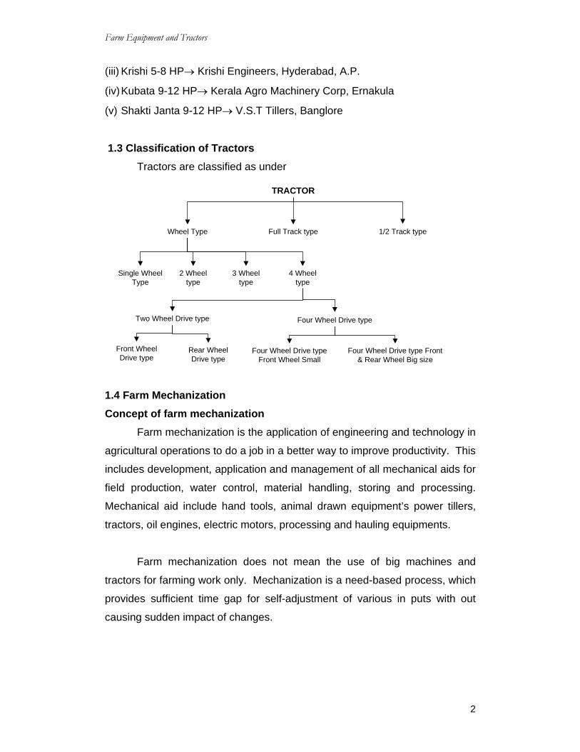
1.3 Classification of Tractors Tractors are classified as under
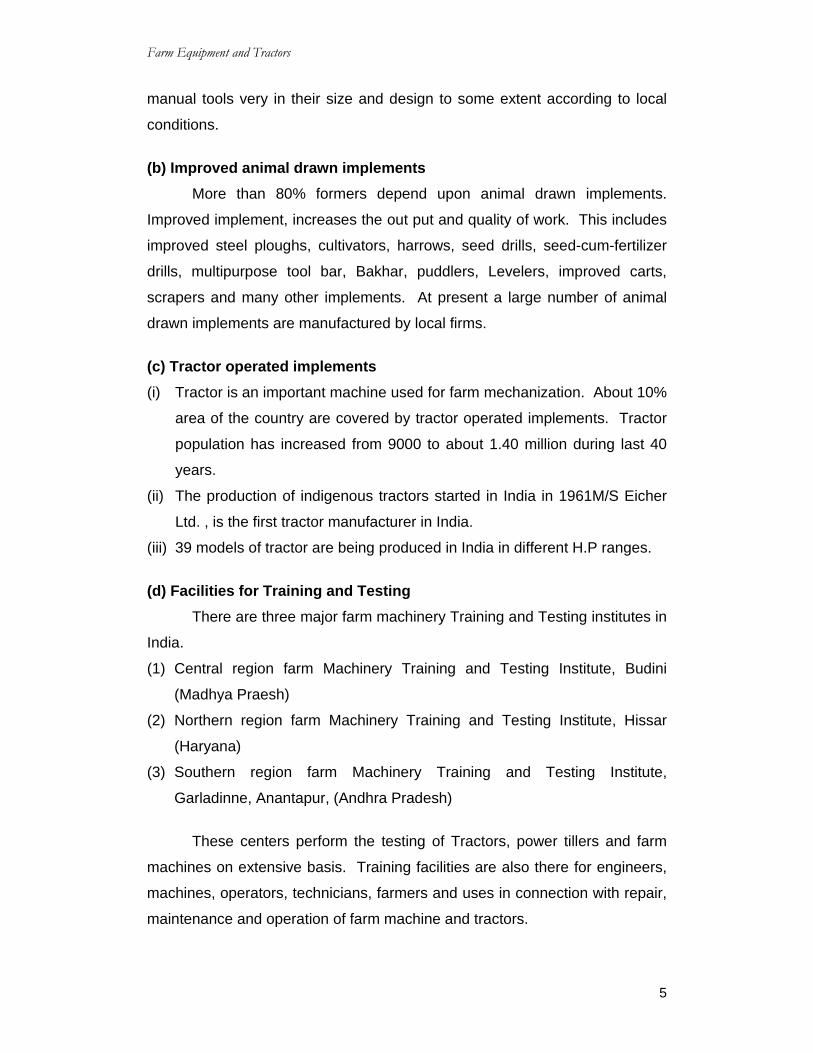
1.4 Farm Mechanization Concept of farm mechanization Farm mechanization is the application of engineering and technology in
agricultural operations to do a job in a better way to improve productivity. This
includes development, application and management of all mechanical aids for
field production, water control, material handling, storing and processing.
Mechanical aid include hand tools, animal drawn equipment’s power tillers,
tractors, oil engines, electric motors, processing and hauling equipments.
Farm mechanization does not mean the use of big machines and
tractors for farming work only. Mechanization is a need-based process, which
provides sufficient time gap for self-adjustment of various in puts with out
causing sudden impact of changes.
TRACTOR
Wheel Type Full Track type 1/2 Track type
Single WheelType
2 Wheeltype
3 Wheeltype
4 Wheeltype
Two Wheel Drive type Four Wheel Drive type
Front WheelDrive type
Rear WheelDrive type
Four Wheel Drive typeFront Wheel Small
Four Wheel Drive type Front& Rear Wheel Big size

Farm Equipment and Tractors
3
1.5 Scope of Farm mechanization This is a good scope of farm mechanization in India due to the
following factors:
(a) Improved irrigation facility in the country.
(b) Introduction of high yielding variety of seeds.
(c) Introduction of high dose of fertilizers and pesticides for different crops.
(d) Introduction of new crops in different parts of the country.
(e) Multiple cropping system and intensive cultivation followed in different
parts of the country.
The above factors are responsible to en courage farm mechanization
which can be viewed with the following parts in mind:
(i) Population of the country is increasing at the rate of about 2.5% per year.
Steps have to be taken to arrange food and fibres for such large
population by adopting intensive farming in the country.
(ii) In multiple cropping programme, where high yielding variety of seeds are
used, all farm operations are required to be completed in limited time with
economy and efficiency. This is possible only with the help of
mechanization.
(iii) Farm mechanization removes drudgery of labour to a great extent. A
farmer has to walk about 66KM on foot while ploughing one hector land
once by bullocks having 15Cm furrows width.
(iv) A large numbers of female workers and children work on farm unwillingly
due to shortage of power. From the human stand point, it is not desirable
that such an arduous duty should be taken from children and females. A
child must go to school and woman must devote time for managing home
affairs to make life pleasant if machines are used:
a) The farmer and his animals can be relieved of hard work.
b) He will do his job with machines, better and quicker.
c) He will get more leisure and devote more time for other works.
d) He will earn better living and enjoy life in nice manner.
(v) The proper utilization of basic inputs like water, seeds and fertilizers, will
be possible only when proper equipments are used.

Farm Equipment and Tractors
4
(vi) There are certain operations which are rather difficult to be performed by
animal power or human labour such as:
a) Deep ploughing in case of deep rooted crops.
b) Killing the pernicious weeds by deep tillage operations.
c) Leveling of uneven land.
d) Land reclamation.
Benefits of farm mechanization
(i) Timelines of operation.
(ii) Precision of operation.
(iii) Improvement of work environment.
(iv) Enhancement of safety.
(v) Reduction of drudgery of labor.
(vi) Reduction of loss of crop and food products.
(vii) Increased productivity of land.
(viii) Increased economic return to farmers.
(ix) Improved dignity of farmer.
(x) Progress and prosperity in rural areas.
1.6 Present status of farm mechanization Present status of farm mechanization in India can be viewed under the
following general categories:
(a) Improved manual tools.
(b) Improved animal drawn implements.
(c) Tractor operated implements.
(d) Facilities for training and testing.
(e) Other stationary equipment’s like threshers, irrigation pumps, sprayers,
dusters etc.,
(a) Improved manual tools Improved manual tool plays important role in minimizing the physical
strain on the worker. It increases the output of worker per unit time. This
category includes sickles, khurpi, pruning knives, wheel hand hoe, long
handle hoes, manually operated seed drills and many such items. The
Farm Equipment and Tractors
5
manual tools very in their size and design to some extent according to local
conditions.
(b) Improved animal drawn implements More than 80% formers depend upon animal drawn implements.
Improved implement, increases the out put and quality of work. This includes
improved steel ploughs, cultivators, harrows, seed drills, seed-cum-fertilizer
drills, multipurpose tool bar, Bakhar, puddlers, Levelers, improved carts,
scrapers and many other implements. At present a large number of animal
drawn implements are manufactured by local firms.
(c) Tractor operated implements (i) Tractor is an important machine used for farm mechanization. About 10%
area of the country are covered by tractor operated implements. Tractor
population has increased from 9000 to about 1.40 million during last 40
years.
(ii) The production of indigenous tractors started in India in 1961M/S Eicher
Ltd. , is the first tractor manufacturer in India.
(iii) 39 models of tractor are being produced in India in different H.P ranges.
(d) Facilities for Training and Testing There are three major farm machinery Training and Testing institutes in
India.
(1) Central region farm Machinery Training and Testing Institute, Budini
(Madhya Praesh)
(2) Northern region farm Machinery Training and Testing Institute, Hissar
(Haryana)
(3) Southern region farm Machinery Training and Testing Institute,
Garladinne, Anantapur, (Andhra Pradesh)
These centers perform the testing of Tractors, power tillers and farm
machines on extensive basis. Training facilities are also there for engineers,
machines, operators, technicians, farmers and uses in connection with repair,
maintenance and operation of farm machine and tractors.

Farm Equipment and Tractors
6
1.7 Limiting factors in farm mechanization The following are the limiting factors in farm mechanization in India.
(a) Small land holdings.
(b) Less investing capacity of farmers.
(c) Agricultural labour is easily available.
(d) Adequate drought animals are available in the country.
(e) Lack of repair and servicing facilities for machines.
(f) Lack of trained man power.
(g) High cost of machines. 1.8 Various Components of tractor Instruments controls and switches.
Fig.1.1
Fig. 1.2. Fig. 1.3.

Farm Equipment and Tractors
7
1.8.1 Starting switch
There are three positions of starting switch. For starting insert the key
in vertical position i.e., ‘OFF’ position, then turn key clock wise to ‘ON’
position, further turn the key, engine should not be cranked for more than
10secs at a time. Next cranking, if required, should be done after a gap of 30
seconds. Never keep the key in ‘ON’ position. This will discharge the battery.
Meter and switches: 1.8.2 Hour Meter: Hour meter indicates working
hours of engine corresponding to 1500
RPM of engine. In addition it also
indicates the engine RPM. While
working in the fields keep throttle at
1500-1800 RPM and for this always
use hand throttle.
1.8.3 Temperature gauge: This indicates the temperature
of the engine. For efficient and safe
working of engine the needle should
always be in Green Zone. Amber
colour zone indicates that the
temperature is approaching danger
zone. Do not run the engine if the
needle is in Red Zone.
Fig. 1.4. Starting Switch
Fig. 1.5. Hour Meter
Fig. 1.6. Temperature gauge

Farm Equipment and Tractors
8
1.8.4 Oil Pressure Gauge This indicates the lubricating oil
pressure of engine. In a new engine it
should be more than 3.5Kg/Cm2. Less
than 1.5 Kg/Cm2 pressure at full load in
hot conditions is not desirable.
1.8.5 Ampere Meter This indicates charging or
discharging of the battery, while engine is
running needle should always be in the
green zone.
1.9 Safety precaution for tractor
maintenance 1. Always park your tractor with gear in neutral position and the parking
brake engaged.
2. Never start the tractor other than from the driving seat.
3. Never run the engine in a closed shed or garage.
4. Always lock the brake pedals when not working in field.
5. Never travel at high speed when operating over rough ground or near
ditches.
6. Avoid sudden braking when hauling a trailer, particularly on bends or on
slippery road surface.
7. Never drive down a hill in neutral.
8. Never leave the tractor seat when the tractor is in motion.
9. Never make any adjustments on the tractor while it is in motion.
10. Never work under an implement when it is in raised position.
11. Never install or remove the belt, while the belt pulley is in motion.
12. Never wear loose cloths while operating belt pulley or any equipment from
P.T.O.
13. Never attempt to clean or adjust PTO driven implement while engine is
running.
Fig 1.7 Bil pressure gange
Fig 1.8 Ampere meter
Farm Equipment and Tractors
9
14. Always pull from draw bar, pulling from the top link or any other
component is dangerous.
15. Never refill the tractor when the engine is running.
16. Ensure all safety shields are in place and in good condition.
17. Allow the engine to cool before removing the Radiator cap.
18. Do not use the independent brakes for making turn on the high way or at
high speed.
1.10 Pre start checks 1. Check water level in the radiator.
2. Check oil level in oil sump
3. Check tire pressure.
4. Make sure that the gear lever is in neutral.
5. Make sure that fuel cut off knob is fully pressed in.
6. Ensure that both brake pedals are inter locked.
7. En sure that parking brakes are detached.
8. Check fuel level in the fuel tank and ensure that fuel cock is in open
position.
1.11 To start the engine 1. Press the clutch pedal.
2. Move the hand throttle lever to 1/3rd of its movement.
3. Push the starting key in the starting switch and turn it clockwise to ‘ON’
position.
4. Further turn the key in clockwise direction to start the engine.
5. Release the starting key immediately after starting to the engine.
6. To select the proper gear, press clutch pedal fully and move H/L gear
shifter to select the proper gear in usual manner. Do not shift gear from
higher speed to lower speed suddenly.
1.12 To stop the Engine 1. Bring hand throttle lever to idling position.
2. Bring gear lever to neutral. 3. Pull fuel cut off knob.
4. Engage parking brakes.

Farm Equipment and Tractors
10
5. Turn starting key to ‘OFF’ position. 6. Take out the key after the work is over, other wise battery may discharge.
1.13 Driving the Tractor 1. Before driving, check all controls, brakes, instruments, light etc., for proper
working.
2. Release parking brakes. 3. Press the clutch pedal.
4. Select the proper gear as required and slowly release the clutch pedal while increasing the rpm by throttle.
1.14 Running in First 50 Hours The running in period i.e., first 50 hours requires some special measure as: 1. Never operate the tractor without load and avoid over loading.
2. Carry out daily checks. 3. Check controls and gauges frequently.
4. The tractor should not be put on load till it attains its normal running temperature.
5. Avoid operating engine at low rpm and high gears. 1.15 Road signals and Rules while driving the tractor on the road 1. Know the road signs well and act accordingly. 2. Drive on the left side of the road, particularly on a curve, a hill or a
crossing.
3. While carrying an implement wider than the tractor, keep a safe gap on
both sides while over taking. 4. Maintain a safe distance from the vehicle ahead.
5. Before turning, give signal and look back to make sure that there is no vehicle close behind.
6. On approaching a road crossing or sharp bend, slow down. 7. Be watch full for children suddenly darting across the road.
8. Cattle have first right to cross the road. 9. Dip the head lights in traffic areas and when approaching another vehicle.
10. Flicker the lights at night to signal to the vehicle ahead for over taking. 11. It is for bidden to use plough lamp as a light on high ways.
12. Tail lamp is fitted with a built in reflector.

Farm Equipment and Tractors
11
Fig. 1.9.
Fig. 1.10

Farm Equipment and Tractors
12
QUESTIONS Short Answer type Questions: 1) What are the main components of Tractor?
2) What are the gauges used in Tractor?
3) What is the use of Temperature gauge in a Tractor?
Essay Type Questions 1) What are the safety precautions to be taken for tractor maintenance?
2) How to start and stop the engine?

Farm Equipment and Tractors
13
Engine
External CombustionEngine
Internal CombustionEngine
Steam Engine Steam Engine Spark Ignition Compression Ignition
Two Stroke Four Stroke Two Stroke Four Stroke
CHAPTER – 2 ENGINE COMPONENTS
2.0 Engine
Any Machine which converts heat energy in to mechanical energy is
called engine.
2.1 Types of Engines
There are various types of engines used in automobile as tabulated
below.
Fig 2.1A Fig 2.1B
2.1.1 External combustion Engine Here the combustion uses heat in form of steam, which is generated in
a boiler, placed entirely separate from the working cylinder.
Internal Combustion Engine Here the combustion of fuel takes place in side the engine cylinder and
heat is generated with in the cylinder of the engine.
There are two ways in which combustion takes place in the cylinder:

Farm Equipment and Tractors
14
(i). By rapid explosion of air-fuel mixture with in the cylinder, when it is
ignited by a spark, is called spark Ignition Engines (or) constant volume
combustion (C.V.C)
(ii). Combustion takes place by slow burning when the fuel in injected into
highly compressed heated air contained in the cylinder. This is called
compression Ignition Engine (or) constant pressure combustion (C.P.C)
because when the combustion takes place, the pressure in the cylinder is
almost constant.
2.1.2 Diesel Engines Compression ignition engines are usually called diesel engines named
after its inventor Dr. Rudolf Diesel. In Diesel engine, only air is charged
through in let valve and is compressed in compression stroke, at the end of
compression stroke diesel oil is sprayed which due to high temperature and
pressure gets ignited and gases expand. There are no spark plugs, in such
engines, charge is ignited due to hot compressed air. It is why they are
known as compression ignition engines.
2.2 Internal combustion Engine components Internal combustion engine consists of a number of parts which are
given below:
(i) Cylinder
It is a part of the engine which confines the expounding gases and
forms the combustion space, it is the basic part of the engine. It provides
space in which piston operates to suck the air or air-fuel mixture. The piston
compresses the charge and the gas in allowed to expand in the cylinder,
transmitting power for useful work. Cylinders are usually made of high grade
cast iron.
(ii) Cylinder block It is the solid costing which includes the cylinder and water jacket
Farm Equipment and Tractors
15
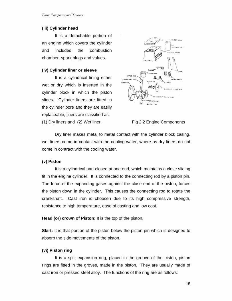
(iii) Cylinder head It is a detachable portion of
an engine which covers the cylinder
and includes the combustion
chamber, spark plugs and values.
(iv) Cylinder liner or sleeve It is a cylindrical lining either
wet or dry which is inserted in the
cylinder block in which the piston
slides. Cylinder liners are fitted in
the cylinder bore and they are easily
replaceable, liners are classified as:
(1) Dry liners and (2) Wet liner. Fig 2.2 Engine Components
Dry liner makes metal to metal contact with the cylinder block casing,
wet liners come in contact with the cooling water, where as dry liners do not
come in contract with the cooling water.
(v) Piston It is a cylindrical part closed at one end, which maintains a close sliding
fit in the engine cylinder. It is connected to the connecting rod by a piston pin.
The force of the expanding gases against the close end of the piston, forces
the piston down in the cylinder. This causes the connecting rod to rotate the
crankshaft. Cast iron is choosen due to its high compressive strength,
resistance to high temperature, ease of casting and low cost.
Head (or) crown of Piston: It is the top of the piston.
Skirt: It is that portion of the piston below the piston pin which is designed to
absorb the side movements of the piston.
(vi) Piston ring
It is a split expansion ring, placed in the groove of the piston, piston
rings are fitted in the groves, made in the piston. They are usually made of
cast iron or pressed steel alloy. The functions of the ring are as follows:
Farm Equipment and Tractors
16
(a) It forms a gas tight combustion chamber for all positions of piston.
(b) It reduces contract area between cylinder wall and piston wall preventing
friction losses and expensive wear.
(c) It controls the cylinder lubrication.
(d) It transmits the heat away from the piston to the cylinder walls.
Piston rings are of two types:
(1) Compression rings and (2) Oil rings
Compression rings: Compression rings are usually plain, single piece and
are always placed in the grooves nearest to the piston head.
Oil rings: Oil rings are grooved or slotted and are located either in lowest
groove, above the piston pin or in a groove above the piston skirt. They
control the distribution of lubrication oil in the cylinder and the piston. They
prevent excessive oil consumption also. Oil ring is provided with small holes
through which excess oil returns back to the crank case chamber. Ring
clearance is the gap at the joint of the ring, measured when the ring is inside
the cylinder. The gap is usually 1mm per 200mm diameter of the piston. This
clearance is necessary for expansion of the ring in heated condition, with out
which the ring can break or buckle.
(vii) Piston pin
It is also called wrist pin or gudgeon pin. Piston pin is used to join the
connecting rod to the piston. It provides flexible or hinge like connection
between the piston and the connecting rod. It is usually made of cases
hardened alloy steel.
(viii) Connecting rod It is special type of rod one end of which is attached to the piston and
the other end to the crankshaft. It transmits the power of combustion to the
crankshaft and makes it rotate continuously. It is usually made of drop for
geed steel. Its small end is fitted with bronze bushing and big end is provided
with bearings split into two shells.

Farm Equipment and Tractors
17
(ix) Crank shaft It is the main shaft of an engine which converts the reciprocating
motion of the piston into rotary motion of the fly wheel, usually the crank shaft
is made of drop forged steel or cast steel.
(x) Fly wheel Fly wheel is made of cast iron. Its main functions are as flows:
(a) It stores energy during power stroke and returns back the same energy
during the idle stroke, providing an uniform rotary motion by virtue of its
inertia.
(b) It also carries ring gear that meshes with the pinion of starting motor.
(c) The rear surface of the flywheel serves as one of the pressure surfaces for
the clutch plate.
(d) It helps in adjusting the timing of the engine.
(e) Some time the flywheel serves the purpose of a pulley for transmitting
power.
(xi) Crank case The crankcases is that part of the engine which supports and encloses
the crankshaft and camshaft. It provides reservoir for lubricating oil of the
engine. It also serves as a mounting unit for such accessories as the oil
pump, oil filter, generator, starting motor and ignition components. The upper
portion of the crankcase is usually integrated with cylinder block. The lower
part of the crankcase is commonly called oil pan and is usually made of cast
iron or cast aluminum.
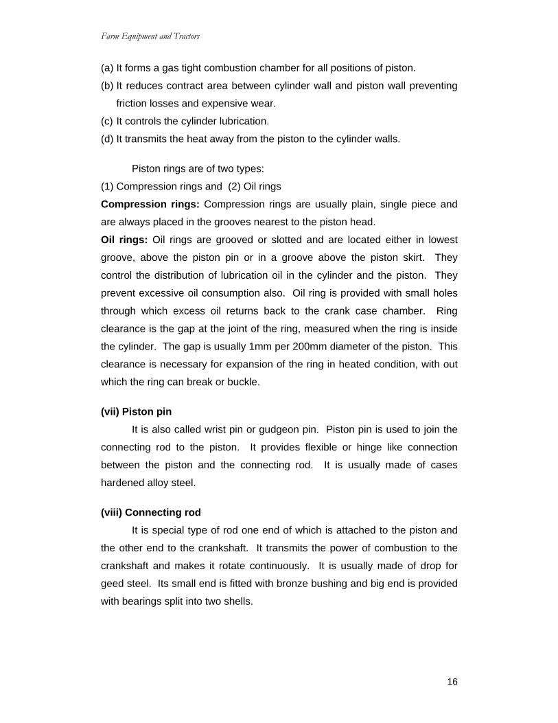
Principle of four-stroke Diesel Engine In four-stroke cycle engines there are four-strokes completing two
revolutions of the crankshaft. These are respectively the suction,
compression, power and exhaust strokes.
Farm Equipment and Tractors
18
(i) Suction Stroke When piston moves from Top Dead Center (T.D.C) to bottom Dead
Center (B.D.C), the inlet valve opens due to down ward movement of piston,
partial vacuum is created in the cylinder above the piston. Due to this air is
sucked inside the cylinder. At the end of suction stroke, in let valve closes.
(ii) Compression stroke
When piston starts moving from B.D.C to T.D.C, the air which has
trapped in the cylinder starts getting compressed, when, piston reaches near
T.D.C, the gasses get so compressed that its temperature reached between
650-800oC. This high temperature is due to higher compression ratio. In this
stroke both valves remain closed.
(iii) Power stroke At the end of compression stroke, diesel oil is sprayed in fine
automised form to the burning hot air and it gets ignited more or less in rapid
explosion. Thus hot expanding gases (temperature between 1650-1925oC)
push the piston down giving us power stroke.
(iv) Exhaust stroke When piston starts moving up, exhaust valve opens and exhaust gases
are let out. In this way complete cycle continues and engine keeps on
running.
Farm Equipment and Tractors
19
2.4 Salient features of four stroke diesel engine (1) Engine has high compression ration from 14:1 to 22:1. (2) During compression stroke, the engine attains high pressure ranging
from 30 to 45 kg km2 and high temperature of about 500oC. (3) At the end of the compression stroke, fuel is injected in to the cylinder
through injectors (atomizers) at a very high pressure ranging from 120 to 200 kg/em2.
(4) Ignition takes place due to heat of compression only. (5) There is external spark in diesel engine. (6) It maintains higher torque for a longer duration of time at a lower speed. (7) Less fuel consumption. (8) Fuel injection does not require maintenance that frequently. (9) Life of the engine is more. (10) It runs good even at idle speed. 2.5 Operation of diesel engine For operation of diesel engine, the piston is placed inside the cylinder
and it is attached to the crankshaft through the connecting rod. The piston is
moved up and down in the cylinder. This up and down motion of the piston is
changed in to rotary motion of crankshaft by the connecting rod. Flywheel is
attached to the rear end of the crankshaft. This makes the shaft revolve
uniformly when the engine is running. The cylinder is tightly closed at the top
by cylinder head which houses inlet and exhaust valves. In let valve admits
air into the cylinder and exhaust valve allows the burnt gases to go out of the
engine. The valves are held closed by valve spring and are made to open by
means of rocker arms, which are operated by camshaft through valve lifters
and push rods. The camshaft and fuel injection pump shaft are driven by the
crankshaft through gears. The fuel supplied by fuel injection pump is injected
into the cylinder through fuel injector fuel is ignited by heat of compression
and piston is forced back by the expanding gases. Thus cycle is repeated.
2.6 Types of combustion chambers A combustion chamber is a space inside the engine, where the
combustion of fuel takes place. In diesel engine, the fuel is automised,
vaporized and burnt inside combustion chamber, where as in sprak ignition

Farm Equipment and Tractors
20
engine atomization of fuel takes place in the carburetor as well as the inlet
manifold, combustion chamber is classified as:
(i) Direct injection chamber and
(ii) Indirect injection chamber.
. (i) Direct injection chamber Fuel is injection directly in the
compressed air of the cylinder. The entire
fuel is not burnt quickly only a part of the fuel
cones in contact with the heated air of the engine which gets ignited
immediately starting of engine is easy in this case.
(ii) Indirect injection chamber It may be two types:
(a) Pre combustion chamber
(b) Air cell chamber
Fig 2.4B Indirect injection chamber
(a) Pre combustion chamber There is small chamber above the cylinder of the engine, which may be
spherical or cylindrical in shape. Fuel is injected directly in this small
chamber. At the time of fuel injection, the air of the chamber is distributed by
the upward movement of the piston. As the combustion takes place, very
high pressure is produced inside the small chamber which forces the unburnt
fuel with high velocity into the main chamber. Starting of the engine is not
very easy due to relatively low temperature of the cylinder.
Farm Equipment and Tractors
21
(b) Air cell chamber It is a space provided in the piston or cylinder to trap air during the
compression stroke. Later air blows out into the combustion chamber. There
is a spherical cavity in the cylinder head, piston head or the cylinder wall, fuel
is injected in the main chamber and combustion of fuel takes place inside the
cylinder. When the piston moves down ward, the air cell discharges air in the
form of spray inside the cylinder which results in rapid burning of the fuel.
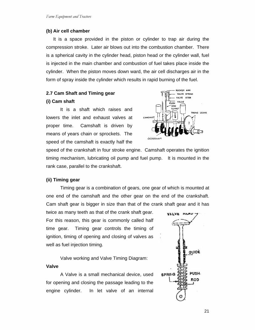
2.7 Cam Shaft and Timing gear (i) Cam shaft It is a shaft which raises and
lowers the inlet and exhaust valves at
proper time. Camshaft is driven by
means of years chain or sprockets. The
speed of the camshaft is exactly half the
speed of the crankshaft in four stroke engine. Camshaft operates the ignition
timing mechanism, lubricating oil pump and fuel pump. It is mounted in the
rank case, parallel to the crankshaft.
(ii) Timing gear Timing gear is a combination of gears, one gear of which is mounted at
one end of the camshaft and the other gear on the end of the crankshaft.
Cam shaft gear is bigger in size than that of the crank shaft gear and it has
twice as many teeth as that of the crank shaft gear.
For this reason, this gear is commonly called half
time gear. Timing gear controls the timing of
ignition, timing of opening and closing of valves as
well as fuel injection timing.
Valve working and Valve Timing Diagram:
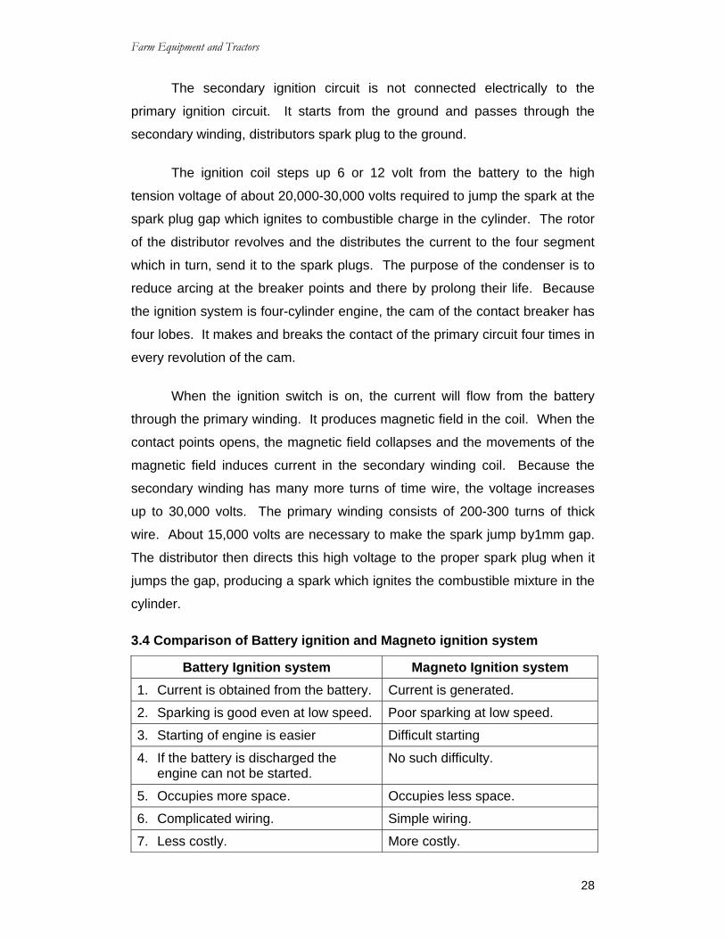
Valve A Valve is a small mechanical device, used
for opening and closing the passage leading to the
engine cylinder. In let valve of an internal

Farm Equipment and Tractors
22
combustion engine allows air or air-fuel mixture to go into the combustion
chamber. The exhaust valve allows burnt gases to go out of the engine
cylinder. Each valve is opened or closed once during each cycle. A strong
spring with the help of retainer and a key holds the valve tightly against the
seat and thus prevents leakage on the compression and power stroke. The
common face and seat angle of valve is 45o but 30o angle is also used for
intake valves. The most common type of valve is called Popet valve (fig.2.7).
Valve head It is made of specially alloy which can with stand high temperature and
hammering action due to expanding gases.
Valve stem It is a round steel rod attached with the valve head.
Valve seat It is the place in the cylinder head where the valve head sits well. It
may be made in cylinder head or in the engine block, some times removable
valve seats are also used.
Valve stem guide It is a small guide, which fits into the cylinder block. It is usually made
of cast iron.
2.7.1 Valve operating mechanism Valve operating mechanism consists of several components such as:
(i) Crankshaft gear; (ii) Cam gear: (iii) Camshaft; (iv) Push rod; (v) Tappet and
(vi) Rocker arm. The cam shaft gear operates the cam gear which is fixed at one end of
the camshaft. Consequently camshaft rotates and moves the tappet, which
pushes the push rod in proper time. Thus push rod opens or closes the pre
determined valves at predator mined intervals. The cam shaft gear is double
the size of the camshaft gear, so there is one revolution of the cam shaft for
every two revolutions of the crankshaft in case of four stroke engine.

Farm Equipment and Tractors
23
Crank shaft gear A gear fixed at the end of the crankshaft which meshes with the gear of
the cam shaft is called crank shaft gear.
Cam gear A gear fixed at the end of the camshaft to mesh with the crankshaft
gear is called cam gear.
Tappet Tappet is also called valve lifter. Tappet raises or lowers the valves. It
receives motion from the cams, mounted on the camshaft. It opens or closes
the valves at proper time. It is usually made of hardened steel.
Valve lifter guide It guides the tappet in motion.
Rocker Arm It is an arm used to change upward motion of push rod to down ward
motion for opening an engine valve. It is a small rod, one end of which
touches the end of the valve stem and the other end touches the upper end of
the tappet rod.
Tappet clearance It is the clearance between rocker arm and valve stem to enable the
valves to sit properly.
2.7.2 Valve Timing Diagram A valve timing diagram is a
diagram of crank rotation on which the
time of opening closing of in let valve,
exhaust valve are shown fig2.8.
Valve timing mechanism is
concerned with relative closing and
opening of valves and their duration with respect to the cylinder position and

Farm Equipment and Tractors
24
the degree of crank shaft rotation. Top center (TDC) is instant when a piston
is at the bottom of its stroke i.e, it is on the point of changing from up ward to
down ward motion Bottem diad centre (B.D.C) is the instant when a piston is
at the bottem of its stroke ie it is on point of changing from down word motion.
Theoretically the intake valve should open on top dead center (TDC) and
close at bottom dead center (BDC), where as the exhaust valve should open
on bottom dead center and close on top dead center, but in actual practice
these angles differ, valve timing is a function of engine speed. The best valve
timing for any given engine can be determined only by actual test, as it
depends greatly on the design of the intake and exhaust passage. For most
of the average tractor engines of four stroke cycle, the in let valve opens
about 5o before TDC and closes at about 30o after BDC, the exhaust valve
opens about 40o before B.D.C and closes at about 5o after TDC.
Firing order The sequence in which the power stroke in each cylinder of an engine
occurs is called firing order. The arrangement of the crank pin on the crank
shaft and design of the cam shaft both determine the firing order. For four
cylinder engine the most commonly used firing order is 1-3-4-2. For six
cylinder engines firing order may be 1-4-2-6-3-5 (or) 1-5-3-6-2-4.
Firing Interval (F.I) The interval between successive power strokes in different cylinders of
the engine is called firing interval and is determined as below.
720o F.I = ---------------------- (for four stroke engine) No. of cylinder 360o F.I = ---------------------- (for two stroke engine) No. of cylinder

Farm Equipment and Tractors
25
QUESTIONS Short Answer Type Questions 1. What are the main parts of Internal combustion engine?
2. What is meant by combustion chamber?
3. What are the valves used in diesel engine?
Essay Type Questions 1. Describe briefly about Internal combustion engine components?
2. Explain the principle of Four-stoke Diesel engine with a neat sketch?
Farm Equipment and Tractors
26
CHAPTER – 3 IGNITION SYSTEM
3.0 Introduction
As the air is a bad conductor of
Electricity, an air gap in an electric circuit, act as a very great
resistance. But when a current of high-tension and high-voltage is passed
across the air-gap, it produce a spark there. When the spark is produced at a
spark plug to ignite the air-fuel mixture in the combustion chamber, then it is
called ignition system. The ignition system is classified as (I) Battery-ignition
systems (ii) Magneto-ignition system (iii) Electronic ignition system.
3.1 Requirements of an Ignition system
The ignition system supplies high voltage of current to the spark plug.
These surges produce the electric spark at the spark plug gap that ignite or
set fire to the compressed air fuel mixture in the combustion chamber. The
sparking must take place at the correct time at the end of compression stroke
in every cycle of operation. At high speed or during part through operation,
the spark is advanced so that it occurs some what earlier in the cycle the
mixture thus has sufficient time to burn and deliver its power. The ignition
system should function efficiently at the maximum and minimum speeds of the
engine. It should be easy to maintain, light and compact. It should not cause
an interference.
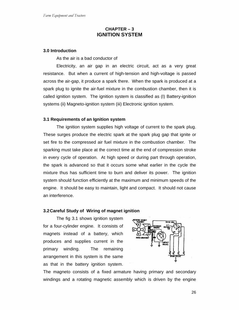
3.2 Careful Study of Wiring of magnet ignition The fig 3.1 shows ignition system
for a four-cylinder engine. It consists of
magnets instead of a battery, which
produces and supplies current in the
primary winding. The remaining
arrangement in this system is the same
as that in the battery ignition system.
The magneto consists of a fixed armature having primary and secondary
windings and a rotating magnetic assembly which is driven by the engine

Farm Equipment and Tractors
27
when the magnets rotate, current flows in the primary winding. The
secondary winding gives high voltage current to the distributor, which
distributes it to the respective spark plugs.
In the magneto, the magnetic field is produced by means of permanent
magnets where has in conventional generator, the magnetic field is produced
by passing some of generated current through the field winding which
produces the magnetic field.
The magneto may be either rotating armature type or rotating magnet
type. In rotating armature type magneto, the armature carrying the primary
and secondary windings and the condenser rotate between the poles of a
stationary horse shoe magnet.
3.3 Battery Coil Ignition-wiring system The fig 3.2 shows
battery ignition system for a
four-cylinder engine. It consists
of a battery ammeter, switch,
ignition coil, condenser,
contact breakers, distributer
and spark plug.
Fig 3.2 Battery coil ignition wiring system
The primary ignition circuit starts at the battery and passes through the
switch, ammeter, primary winding, contact breaker points to the ground. A
condenser is also connected in parallel to the contact breaker points. One
end of condenser is also connected in parallel to the contact breaker point.
One end of condenser is connected to the contact breaker point arm and the
other end is grounded.
Farm Equipment and Tractors
28
The secondary ignition circuit is not connected electrically to the
primary ignition circuit. It starts from the ground and passes through the
secondary winding, distributors spark plug to the ground.
The ignition coil steps up 6 or 12 volt from the battery to the high
tension voltage of about 20,000-30,000 volts required to jump the spark at the
spark plug gap which ignites to combustible charge in the cylinder. The rotor
of the distributor revolves and the distributes the current to the four segment
which in turn, send it to the spark plugs. The purpose of the condenser is to
reduce arcing at the breaker points and there by prolong their life. Because
the ignition system is four-cylinder engine, the cam of the contact breaker has
four lobes. It makes and breaks the contact of the primary circuit four times in
every revolution of the cam.
When the ignition switch is on, the current will flow from the battery
through the primary winding. It produces magnetic field in the coil. When the
contact points opens, the magnetic field collapses and the movements of the
magnetic field induces current in the secondary winding coil. Because the
secondary winding has many more turns of time wire, the voltage increases
up to 30,000 volts. The primary winding consists of 200-300 turns of thick
wire. About 15,000 volts are necessary to make the spark jump by1mm gap.
The distributor then directs this high voltage to the proper spark plug when it
jumps the gap, producing a spark which ignites the combustible mixture in the
cylinder.
3.4 Comparison of Battery ignition and Magneto ignition system
Battery Ignition system Magneto Ignition system 1. Current is obtained from the battery. Current is generated.
2. Sparking is good even at low speed. Poor sparking at low speed.
3. Starting of engine is easier Difficult starting
4. If the battery is discharged the engine can not be started.
No such difficulty.
5. Occupies more space. Occupies less space.
6. Complicated wiring. Simple wiring.
7. Less costly. More costly.

Farm Equipment and Tractors
29
8. Spark intensity falls. Spark intensity improves as the engine speed rises.
9. Used in cars, buses, trucks Used in motor cycles, scooters, racing cars.
3.5 Electronic Ignition Wring Circuit Study In the electric ignition system a
timer is employed in the distributors
instead of contact breaker. This timer
may be a pulse generator or a Hall-
effect switch which triggers the
ignition module, also called the electronic ignition control unit primarily
contains transistor circuit whose base. Current is triggered off and on by the
timer, which results in the stopping and starting of the primary current. Other
than this the electronic ignition system works similar to the conventional
electrical point-type system.
3.6 Fuel system of Diesel Engine During engines
operation, the fuel is
supplied by gravity from
fuel tank to the primary
filter where coarse
impurities are removed.
From the primary filter, the
fuel is drawn by fuel transfer pump and is delivered to fuel injection pump
through second fuel filter. The fuel injection pump supplies fuel under high
pressure to the injectors through high pressure pipes. The injectors atomize
the fuel and inject it in to the combustion chambers of the engine. The fuel
injection pump is fed with fuel in abundance. The excess fuel is by passed to
the intake side of the fuel transfer pump through a relief value.

Farm Equipment and Tractors
30
3.7 Main components of the fuel system in Diesel Engine The main components of the fuel system in Diesel engine are (1) fuel
filter, (2) fuel lift pump (3) fuel injection pump, (4) Atomizers and (5) High
pressure pipe.
The fuel goes from the fuel tank to the first filter, then to fuel lift pump,
then to second filter, then to fuel injection pump and then to the atomizers. On
some tractors and industrial engines, the fuel system is by gravity and hence
no fuel lift pump is provided.
3.8 Fuel filter It is a device to remove dirt from
fuel oil. Solid particles and dust in
diesel fuel are very harmful for giving a
fine degree of filtration. Fuel injection
equipment in diesel engines are
extremely sensitive to dirt and solid
particles present in fuel. A filter is used to remove dirt and solid particles from
the fuel ensure trouble free fuel supply. It consists of a hallow cylindrical shell.
Filtering elements will be packed inside the shell. The filtering elements
consists of fibers, woven cloth, felt, paper etc. These filters are replaced at
certain intervals, specified by the manufactures.
Usually there are two filters in Diesel Engine (a) Primary filter and (b)
secondary filter.
The primary filter removes water and course particle of dirt from the
fuel. The secondary filter removes fine sediments from the fuel. Usually the
primary filter is placed between the tank and the transfer pump.
3.9 Fuel lift pump Feed pump / Transfer pump It is a pump which transfers fuel from the fuel line to the fuel injection
pump. It is mounted on the body of fuel injection pump. It delivers adequate
amount of fuel to the injection pump.

Farm Equipment and Tractors
31
3.10 Fuel Injection Pump It is a pump which delivers metered
quantity of fuel to each cylinder at
appropriate time under high pressure.
Tractor engines may use two types of fuel
injection pump. (a) Multi elements pump and
(b) Distributor (Rotary) type pump.
(a) Multi element pump
The plunger reciprocates in close fitting barrel, the upper part of the plunger has got helix. The helix makes it possible to vary the delivery of the
fuel. An annular groove in the central part of the plunger facilitates the distribution of fuel over the barrel. The plunger reciprocates in the barrel with
the help of tappet and spring. As the plunger moves down fuel enters the barrel from inlet side. As plunger moves up, it closes the inlet part of the
barrel. It pressurizes the fuel in the barrel. This causes delivery valve to life off its seat and allows the fuel to enter in to the injection line leading to the fuel
injector. As soon as the edge of the helix uncovers the spilt part of the barrel, the fuel pressure quickly drops.
It is a high pressure pump used in diesel engine. It creates very high
pressure in the fuel pipe for injecting fuel in to the engine cylinder. It is used
to create pressure varying from 120 Kg/Cm2 to 300 Kg/Cm2 in the fuel pipe for
injector of the diesel fuel in the engine cylinder. It consists of the following main components: (I) Pumping housing (ii) Pump elements (iii) control rock
(iv) Delivery valve.
(i) Pump housing
It is a housing in which cam shaft is suspended by two bearings and it
is driven by engine. It is generally made of cast aluminum or cast iron. (ii) Pump elements
It is a very important part of fuel injection pump. It consists of a plunger
and barrel. Plunger operates in the barrel and creates very high pressure in the fuel flow.

Farm Equipment and Tractors
32
(iii) Control rack
It is a component which is connected to the linkage of the governor for controlling the quantity of the fuel.
(iv) Delivery Valve It is a type of valve which prevents reverse flow of fuel in the high
pressure pipe.
(b) Distributor (Rotary) Type injection pump
In this type of pump, one plunger and one barrel assembly deliver fuel
not to one cylinder but to several cylinders. The plunger not only reciprocates
but rotates also in close fitting barrel. This helps in distributing fuel to a
number of cylinders in turn. In the upper part of the barrel, there are inlet
parts through which fuel enters the barrel. There are delivery passes
connecting the barrel bore with the inclined passages drilled in the head.
Through this passage fuel is delivered to delivery valve holder. From there
the fuel goes to the appropriate injectors through high pressure pipes. The
barrel is sealed on the out side by rubber rings.
3.11 Injector Nozzles Nozzle
The function of the fuel nozzle is to convert the pressure energy of the
oil in to the kinetic energy by passing it through the orifice of the nozzle out
let. Some times it is also called the injector tip. It consists of the nozzle body
and needle in one unit. The nozzle body and needles are made of high grade
steel.
The nozzles of injectors are of three types:
(i) Hole type: (a) Single hole _having only one hole and (b) Multi-hole-having
more than one hole
(ii) Pintle type:
(iii) Conical (or) circumferential or disc type
(i) Hole type Nozzle
(a) Single hole Nozzle (b) Multi hole Nozzle

Farm Equipment and Tractors
33
Single hole nozzles have only one spray hole, drilled either centrally or
conically. On multi hole nozzles, the spray holes from an angle in relation to
each other up to 180o. The maximum number of holes can be 12 depending
on the requirements of the engine. The hole diameter and hole length affect
the shape and depth of penetration of the spray. The hole can be of any
diameter from 0.2mm up words.
(ii) Pintle type nozzle
The nozzle needle of the pintle nozzle is
extended to form a pin or pintle, which projects into
the injection hole of the nozzle body. By varying the
size and shape of the pintle sprays varying from a
hallow parallel sided pencil form up to a hallow cone
with an angle of 60o or more. The main advantage
of this type of nozzle is that the carbon does not
deposit in the injection hole.
Fig 3.9
(iii) Conical or Circumferential or Disc type
This contains a disc placed beneath a single
hole orifice. it breaks the fuel stream into a thin plat
sheet and thus distributes the highly atomized fuel
to the cyclinder.
Fig 3.10
GOVERNOR 3.12 Introduction Governor is a mechanical device designed to control the speed of an
engine with in specified limit used on tractor or stationary engines for:
(i).Maintaining a nearly constant speed of engine under different load conditions.
(ii).Protecting the engine and the attached equipment’s against high speeds, when
the load is reduced or removed.

Farm Equipment and Tractors
34
Tractor engines are always fitted with governor. There is an important
difference in principle between the controls of a tractor engine and that of a
motor car. In case of motor car the fuel supply is under direct control of the
accelerator pedal but in tractor engine, the fuel supply is controlled by the
governors. The operators change the engines speed by moving the governor
control lever.
A governor is essential on a tractor engine for the reason that load of
the tractor engine is subjected to rapid variation in the field and the operator
can not control the rapid change of the engine speed with out any automatic
device.
A governor automatically regulates the engine speed on varying load
condition and thus the operators is relieved of the duty of constant regulating
the throttle lever to suit different load conditions.
3.13 Principle of Governor Engine governor is used for automatically controlling the speed of an
engine by regulating the in take of fuel or injection of fuel, so that engine
speed in maintained at the desired level under all conditions of loading.
During operation, the load on the tractor engine frequently varies
depending up on condition of ground, soil and attached implements. These
load variations cause the engine speed to change accordingly. When the
load on the engine speed may rise beyond safe limit causing (1) chances of
accident (2) Excessive wear of the engine parts (3) Increased fuel
consumption. For better field performance, the moving speed and power take
off speed for implements and machines should not vary much. This can only
be done if the amount of air fuel mixture or fuel delivered to the engine
cylinder, is varied according to changes in the engine speed. Governor used
on tractor engine is called variable speed governor and the one used on
stationary engine is called constant speed governor.
3.14 Classification of Governors

Farm Equipment and Tractors
35
Governors are classified as:
(i) Centrifugal governor
(ii) Pneumatic governor and
(iii) Hydraulic governor.
(i) Centrifugal governor
The main principle of a
centrifugal governor lies in the facts
that when a weight rotates about a
point, it tends to fly away in
tangential direction from the center
of rotation. If the weight is
constrained by a linkage, it can be
made to operate a control lever.
Fig 3.11 Centrifugal governor Centrifugal governor consists of:
(i) Spring loaded centrifugal weights
(ii) Sliding collar,
(iii) Throttle valve
(iv) Spring
(v) Connecting rod.
The connecting rod controls the throttle value, provided in the air fuel
passage. The centrifugal weights may be either mounted on the engine crank
shaft or on another shaft driven by the crank shaft. The sliding collar moves
along the axis of the shaft, depending up on the speed of centrifugal weight.
The distance between the weights is directly proportional to the centrifugal
force and inversely proportional to the spring tension. At low loads, the
engine speed tends to go high the centrifugal weight tend to fly outward
against spring tension there by closing the throttle value and reducing the
entry of charge inside the engine. Similarly at high loads, the speed tends to
become slower, and the centrifugal weights come closes due to spraying
tension. The concentration of the weights causes the throttle to open fully,

Farm Equipment and Tractors
36
allowing more fuel to come in the engine cylinder to increase the speed of the
engine. Centrifugal governor is very common on tractors and stationary
engines.
(ii) Pneumatic governors: Pneumatic governor is used on both petrol engine and diesel engine. It
consists of:
(i)Diaphragm, (ii) Thrust lever, (iii) control rod (iv) Flexible tube (v) Venture
valves (vi) Control lever (vii) Pull button (viii) Acceleration pedal.
In such governors, a
pressure depression is created
in the engine in take manifold,
which causes the diaphragm to
operate a lever connected to the
control rod of the fuel injection
pump in diesel engine or to the
connecting lever of the throttle
value in corroborator engine.
There are two chambers in the diaphragm unit (a) Atmospheric chamber,
which is connected to the atmosphere and (b) vacuum chamber, which is
connected to the venturi unit. A leathers, diaphragm separates these
compartments. Difference of pressure in the venture tube is communicated to
the diaphragm chamber to operate the spring loaded diaphragm and pump
control rod. There is a vacuum pipe which connects the air tight chamber on
one side of the diaphragm and the venturi tube intake manifold. There is
butterfly value is actuated by a throttle lever. When the throttle lever is
operated the butterfly valve is moved and a change is brought in the pressure
at the venturi throat. This pressure change is transmitted to the diaphragm
through the vacuum pipe. The diaphragm either moves back against the
spring or is moved out wards by the spring. The movement of diaphragm
actuates the control rod of fuel injection pump or the throttle lever of the
carburetor to increase or decrease the fuel supply. Thus controlling the
engine speed. This type of governor is popular on small engines.

Farm Equipment and Tractors
37
Fig 3.13
(iii) Hydraulic Governor This governor is based on that the change of pressure in one part of
the system. Produces an opposite change of much greater magnitude in
another past. A pump is used to deliver the oil from the fuel injection pump in
to a chamber called amplifier under pressure. Pressure drop depends up on
the amount of oil flowing i.e, upon on pump speed which is in turn dependent
up on engine speed. Movement of the piston against spring pressure moves
the control rod to open piston increase the pump delivery. End thrust on the
amplifier piston tends to open the amplifier valve, but is resisted by the control
spring. Depression of the accelerator compresses the spring and increases
the load on the amplifier valve which opens at a pressure that depends up on
the control position, selected by the driver. An idling valve is provided to give
greater sensitively under idling conditions when the rate of oil flow is low. This
type of governor is not in common use for tractor and small stationary
engines.
3.15 Intake and Exhaust System: Introduction: The intake and exhaust system deals with the inflow of fresh air and
out flow of used gases in the engine.
In tractors Intake and Exhaust (muffler) system consists of air cleaner,
inlet–manifold Exhaust-manifold. Exhaust pipe, Exhaust muffler and pre-
cleaner fitted above the air cleaner. The general of the intake and Exhaust
system is shown in fig 3.13.
Farm Equipment and Tractors
38
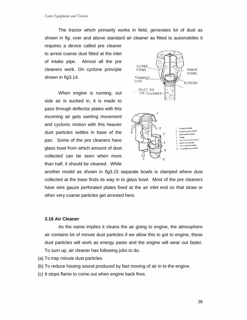
The tractor which primarily works in field, generates lot of dust as
shown in fig. over and above standard air cleaner as fitted to automobiles it
requires a device called pre cleaner
to arrest coarse dust fitted at the inlet
of intake pipe. Almost all the pre
cleaners work. On cyclone principle
shown in fig3.14.
When engine is running, out
side air is sucked in, it is made to
pass through deflector plates with this
incoming air gets swirling movement
and cyclonic motion with this heavier
dust particles settles in base of the
pan. Some of the pre cleaners have
glass bowl from which amount of dust
collected can be seen when more
than half, it should be cleaned. While
another model as shown in fig3.15 separate bowls is clamped where dust
collected at the base finds its way in to glass bowl. Most of the pre cleaners
have wire gauze perforated plates fixed at the air inlet end so that straw or
other very coarse particles get arrested here.
3.16 Air Cleaner As the name implies it cleans the air going to engine, the atmosphere
air contains lot of minute dust particles if we allow this to got to engine, these
dust particles will work as energy paste and the engine will wear out faster.
To sum up, air cleaner has following jobs to do.
(a) To trap minute dust particles
(b) To reduce hissing sound produced by fast moving of air in to the engine.
(c) It stops flame to come out when engine back fires.

Farm Equipment and Tractors
39
3.17 Types of Air Cleaners There are two types of air cleaners i.e,
(a) Wet type (oil both type) (b) dry type.
Wet type of air cleaner
These types of air cleaners was
standard fitting commonly used. One
such their air cleaner is shown in fig3.16.
In this air enters under the top cover and
made to deflect over the oil in the bowl.
When dusty air strikes the oil surface,
heavier dust particles stick to the oil and
later on settle at the base of pan.
When the air strikes the oil, certain quantity of oil also tries to go along
with it, to trap the oil, wire gauge element is fitted which remains wet, it also
does not allow dust particles to go to engine.
3.18 Maintenance of wet type air cleaner At each service drain the oil from the oil bowl, clean the bowl clean the
wire gauze elements bowl air to clean oil traces. Fill up clean engine oil in the
blow up to level mark and clamp it back, as shown in fig 3.18.
(b) Dry air cleaner Dry type air cleaners are usually
known as paper type of filter, the
construction of filter is shown in fig. You
will see that filter paper is made in corrugated form to increase cleaning area
the paper element can be cleaned by blowing air from inside dust sticking will
fall off, if found dusty they should be replaced. Sometimes very minute hole

Farm Equipment and Tractors
40
develop in the filter which are not seen by naked eye. To inspect the filter put
an electric bulb inside the filter. If filter is punctured you would be able to see
the light clearly do not repair, replace it.
3.19 Pre – Cleaners Tractors always work in dusty conditions. In order to prolong the
engine life. Pre-cleaners are fitted in the upper portion of the main cleaner.
When the engine is running, the air is drawn through the pre-cleaner to the
inlet tube of the main cleaner. Here large dust particles are removed from the
air steam, thus reducing much of the load on the main cleaners.
The Pre-cleaner functions on the centrifugal principle. By means of
vanes and baffles, it gives a rotary motion to the air, thus causing the heavier
dust particles to be thrown out due to centrifugal force and the pre-cleaned air
passing to the cleaner.
The servicing of the air cleaner is an important factor in efficient engine
performance.
3.20 Super Chargers A super charger is a device for increasing the air pressure in to the
engine so that more fuel can be burnt and the engine out put increased. The
pressure inside the manifold of a super charge engine will be greater than the
atmospheric pressure. Super charged air is provided either by positive
displacement rotary blowers or by centrifugal blowers. These may be driven
(a) by the engine it self, (b) from a separate power source such as an electric
motor and (c) from an exhaust gas turbine. This is an auxiliary unit and only
high horse power range engines are provided with super charger.
3.21 Inlet and exhaust manifold Inlet / intake manifold:
The inlet manifold is
required to deliver in to the
cylinders either a mixture of fuel
and air from the carburetor or only
air from air cleaners.
Farm Equipment and Tractors
41
The inlet manifolds are made in one or two pieces either from cast iron
or aluminum alloy. They are also bolted from separate castings in to a single
unit. The manifold flankers are connected to the cylinder block or cylinder
head by means of asbestos, copper gaskets, studs and nuts.
Exhaust Manifold The exhaust system collects exhaust gases from the engine and
expels then out. The exhaust manifold collects exhaust gases from the
exhaust ports of various cylinders and conducts them from each end to a
central exhaust passage. It is usually made of cast iron. The exhaust
manifolds are designed to avoid the over lapping of exhaust strokes as much
as possible, thus keeping the back pressure to a minimum. This is often done
by dividing the exhaust manifolds in to two or more branches so that no two
cylinders will exhaust in to the same branch at the same time.
3.22 Turbo Charger This is an exhaust driven turbine which drives a centrifugal compressor
wheel. The compressor is usually located between the air cleaner and engine
intake manifold, while the turbine is located between the exhaust manifold and
muffler.
3.23 Muffler The muffler reduces the noise of the exhaust gases by reducing the
pressure of the used gases by slow expansion and cooling. On the other
hand, the muffler must not cause any appreciable restriction to the flow of oil
that could raise the backpressure excessively. The muffler contains a number
of chambers through which the gas flows. The gas is allowed to expand form
the first passage in to a much larger second one and then to a still larger third
one and so on, to the final and the largest passage which is connected to the
tail pipe of the muffler.
3.24 Cooling System of I.C Engine 3.24.1 Necessity of cooling system The cooling system is provided in the Internal combustion (IC) engine
for the following reasons.

Farm Equipment and Tractors
42
(a) The temperature of the burning gases in the engine cylinder reaches up to
1500-2000oC. Which is above the melting point of the material of the cylinder
body and head of the engine. (Platinum a metal which has one of the highest
melting points, melts at 1750oC, iron at 1530oC and aluminum at 657oC.)
Therefore if the heat is not dissipated it would result in the failure of the
cylinder material.
(b) Due to very high temperature, the film of the lubricating oil will get oxidized
thus producing carbon deposits on the surface. This will result in piston
seizure.
(c) Due to over heating, large temperature differences may lead to a distortion of
the engine components due to the thermal stresses set up. This makes if
necessary for the temperature variation to be kept to a minimum.
(d) Higher temperature also lower the volumetric efficiency of the engine.
3.24.2 Requirements of efficient cooling system The two main requirements of an efficient cooling system are.
(a) It must be capable of removing only about 30% of the heat generated in the
combustion chamber. Too much removal of heat lowers the thermal
efficiency of the engine.
(b) It should remove heat at a fast rate when the engine is hot. During the
starting of the engine, the cooling should be very slow so that the different
working parts reach their operating temperature in a short time.
3.25 Types of engine cooling system A system which controls the engine temperature is known as a cooling
system. There are two types of cooling systems:
(a) Air cooling system and
(b) Water cooling system
(a) Air cooling system
In this type of cooling system, the heat which is conducted to the outer
parts of the engine is radiated and conducted away by the stream of air which
is obtained from the atmosphere. In order to have efficient cooling by means
of air, the contact area is increased by providing fins around the cylinder and

Farm Equipment and Tractors
43
cylinder head, the hot spots of the
engine. The fins are metallic ridges
which are formed during the casting
of the cylinder and cylinder head.
The amount of heat carried off
by the air-cooling depends up on the
following factors:
(i) The total area of the fin surfaces
(ii) The velocity and amount of the
cooling air and
(iii) The temperature of the fins and of the
cooling air.
Air-cooling is mostly used in
motor cycles, scooters, small cars and small aircraft engines where the
forward motion of the machine gives good velocity to cool the engine. Air-
cooling is also provided in some small industrial engines. Now a days, some
tractors (Viz. Eicher, Kirloskar 4006K, Harsha T-25) have also been provided
with air cooling systems. In this system, individual cylinders are generally
employed to provide cooling area by providing fins. A blower is used to
provide air.
Advantages of Air-cooled Engines Air-cooled engines have the following advantages:
1. Its design of air cooled engine is simple
2. It is lighter in weight than water-cooled engines due to the absence of water
jackets, radiator, circulating pump and weight of the cooling water.
3. It is cheaper to manufacture
4. It needs less care and maintenance
5. This system of cooling is particularly advantages where there are extreme
climatic conditions in the arctic or where there is scarcity of water a in deserts.
6. No risk of damage from frost, such as cracking of cylinder jackets or radiator
water tubes.
(b) Water cooling system

Farm Equipment and Tractors
44
Engines, using water as cooling medium is called water cooled
engines. The liquid is circulated round the cylinders to absorb heat from the
cylinder walls. In general, water is used as cooling liquid.
The heated water is conducted through a radiator which helps in
cooling the water. There are three common methods of water cooling
(i) Open jacket or hopper method
(ii) Thermosiphon Method
(iii) Forced circulation method
(i) Open jacket or hopper method
There is a hopper or a jacket
containing water, which surrounds the
engine cylinder so long as the hopper
contains water, the engine continues to
operate satisfactorily. As soon as the
water starts boiling, it is replaced by cold
water. The hopper is larger enough to run
for several hours with out refilling. A drain
plug is provided in a low accessible
position for draining water as and when
required. This system is not common in
present days.
(ii) Thermosiphon Method This is one of the oldest systems working on principle that when water
is heated up it becomes light and water which is cold at top being heavy goes
down. In this way water starts circulating. This system is not being used in
tractors due to following reasons but how ever it is more popular being cheap
in stationary Diesel engines where big 200lit. Water drum is placed near
engine and engine gets cooled through water circulation.
Disadvantages

Farm Equipment and Tractors
45
1. More quantity of water is required.
2. Radiator should remain filled up with water up to mouth failing which system
will not work.
3. In case of choked hose pipe system will not work.
4. More quantity of water has to be carried.
(iii) Forced circulation method (or) Pump circulation system In this method, a water
pump is used to force water from
the radiator to the water jacket of
the engine. After circulating the
entire run of water jacket, water
comes back to the radiator where
it loses its heat by the process of
radiation. To maintain the correct
engine temperature, a thermostat valve is placed at the out end of cylinder
head. Cooling liquid is by passed through the water jacket of the engine until
the engine attains the desired temperature. Then thermostat valve opens and
the by pass is closed, allowing the water to go to the radiator. The system
consists of: (a) water pump (b) Radiator (c) Fan (d) Fan belt (e) Water jacket
(f) Thermostat valve (g) Temperature gauge (h) Hose pipe.
(a) Water pump It is a centrifugal type pump. It has a casing and an impeller, mounted
on a shaft. The casing is usually made of cast iron. Pump shaft is made of
some non-corrosive material. At the end of the shaft, a small pully is fitted
which is driven by a v-belt. Water pump is mounted at the front end of the
cylinder block between the block and the radiator. When the impeller rotates,
the water between the impeller blade is thrown out wood by centrifugal force
and thus water goes to the cylinder under pressure. The pump out let is
connected by a hose pipe to the bottom of the Radiator. The impeller shaft is
supported on one or more bearings. There is a seal, which prevents leakage
of water.

Farm Equipment and Tractors
46
(b) Radiator Radiator is a device for cooling
the circulating water in the engine. It
holds a large volume of water in close
contact with a large volume of air, so
that heat is transferred from the water to
the air easily.
Hot water flows in to the radiator at the top and cold water flows out
from the bottom. Tubes or passages carry the water from the top of the
radiator to the bottom, passing it over a large metal surface. Airflow between
the tubes or through the cells at right angle to the downward flowing water.
This helps in transferring the heat from the water to the atmosphere.
Radiator is made up of following parts as shown in fig (i) upper tank, (ii)
Radiator core (iii) lower tank (iv) Radiator cap.
(i) Upper tank
Upper tank is mostly made of copper sheet, it has a mouth at top for
filling up water on which radiator cap is fitted-on the mouth of a small pipe is
brazed with which rubber pipe is fixed. This pipe is known as leak off pipe.
When water gets over heated steam is generated. This steam leaks past this
pipe. On the upper tank is brazed another pipe, Which is connected to
Engine block with the help of hose pipe.
(ii) Radiator Core Radiator core consists of small brass pipe. On these pipes fins are
brazed so that cooling area is increased. These pipes are connected to upper
and lower tank. These are different designs of pipes are core such as tubular
type, pressed tube type-Honey comb type. Out of these, press tube type is
most commonly used as it is easier to clean in case it gets clogged with
impurities present in water.
Farm Equipment and Tractors
47
(iii) Lower tank Lower tank is also made like upper tank out of brass sheets, water from
upper tank comes to the lower tank through radiator core at the lower tank
pipe is brazed which in turn is connected to Engine block with hose pipe.
(iv) Radiator Cap In open system an ordinary lid cap is used while in pressured cooling
system pressure cap is used. Ordinary water boils at 100oC at sea level; in
case we boil the water on mountain i.e., at higher altitude it will boil at 90oC
while if we boil the water in deep well, it will boil at 110oC, taking advantage of
atmospheric pressures. We use spring loaded valve cap, which maintains a
pressure of 0.7 Kg/Cm2 with this boiling point rises to about 105/110oC.
(c) Fan
The fan is usually mounted on the water pump shaft. It is driven by the
same belt that drivers the pump and the dynamo. The purpose of the fan is to
provide strong draft air through the radiator to improve engine cooling.
(d) Water jackets
Water jackets are cored out around the engine cylinder so that water
can circulate freely around the cylinder as well as around the valve opening.
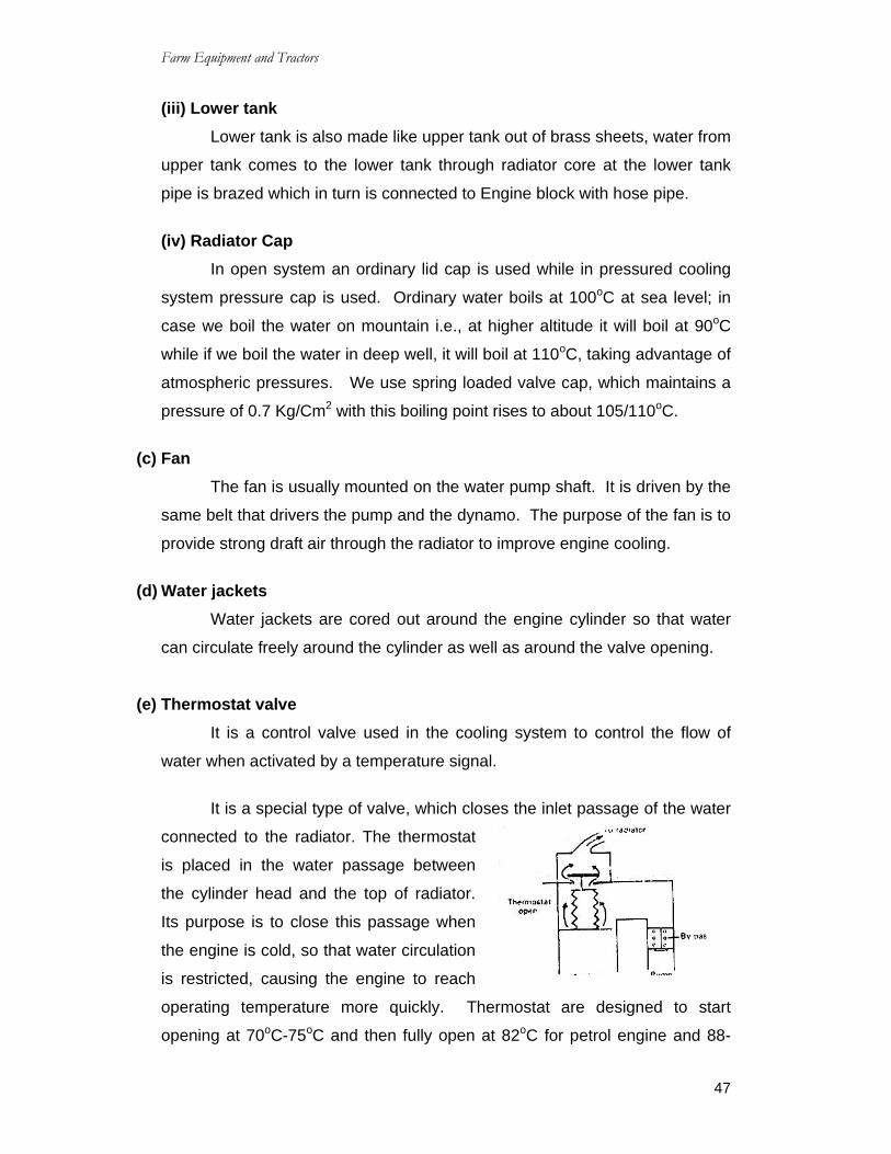
(e) Thermostat valve It is a control valve used in the cooling system to control the flow of
water when activated by a temperature signal.
It is a special type of valve, which closes the inlet passage of the water
connected to the radiator. The thermostat
is placed in the water passage between
the cylinder head and the top of radiator.
Its purpose is to close this passage when
the engine is cold, so that water circulation
is restricted, causing the engine to reach
operating temperature more quickly. Thermostat are designed to start
opening at 70oC-75oC and then fully open at 82oC for petrol engine and 88-

Farm Equipment and Tractors
48
90oC for diesel engine. The thermostat valves are of two types: (a) Bellows
and (b) Bimetallic.
(i) Bellows type thermostat valve
Flexible bellows are filled with
alcohol or ether. When the bellow is
heated, the liquid vaporises, creating
enough pressure to expand the bellows
when the unit is cooled, the gas condenses or converts its phase to liquid.
The pressure reduces and the bellows collapse to close the valve.
(ii) Bimetallic type thermostat valve This consists of a bimetallic strip. Bimetallic strip is made of two or
more different metal composition. The unequal expansion of two metallic
strips causes the valve to open and allows the water to flow in the radiator.
3.26 Cooling System Troubles Due to defective cooling system, several adverse effects are noticed
such as:
(1) Over heating and
(2) slow warm up of the engine.
Over heating is mostly due to:
(a) Accumulation of rust and scale in the radiator and water-jackets.
(b) Defective hose pipe
(c) Defective thermostat
(d) Defective water pump
(e) Loose fan belt
(a) Rust and scale accumulate in the radiator and water jackets. They restrict the
circulation of water in the passage. Due to such restriction engine is over
heated. Rust is caused by the oxidation of ferrous parts of the cooling
system. It has got tendency to clog water passage and to insulate the iron
part from the cooling liquid. Rust can be prevented by the use of suitable
protectives.
Farm Equipment and Tractors
49
Scale is a hard deposit inside the water passage. It acts as a barrier to
the flow of heat from the cylinder to the water.
(b) Some times, there is leakage in the hose pipe and consequently the water in
the radiator is exhausted very quickly.
(c) Some times the thermostat is stuck up in its seats due to some distortion and
it does not function properly. Slow worm up of the engine is mainly due to
defective thermostat.
(d) Defective water pump disturbs completely the circulation of water in the
system.
(e) Loose fan belt causes slippage on the pulley and reduces effectiveness of
cooling.
Care and maintenance of cooling system
1. Clean and fresh water should be filled in the radiator.
2. Lime free water should be used in the radiators as for as possible for
prevention of scale formation.
3. Rotten or soft hose pipe should not be used in the system.
4. The tension of the fan belt should be checked very frequently.
5. Oil and grease should always be kept away from the belt. Greasy belts
should be wiped clean with a rag.
6. The bearing on the water pump should be lubricating regularly.
7. Very hot engines should never be filled with cold water, to avoid fracture in the
cylinder wall and the cylinder head.
8. Radiator and water jackets should be flushed out with special air pressure
guns. Radiator can be cleaned by blowing air with compressed air. This
process will removes bugs, leaves and dirt from the radiator.
9. The cooling system should be cleaned at suitable intervals to remove rust and
scale.
3.27 Lubrication System Introduction Internal combustion engine is made of many moving parts. Due to
continuous movement of two metallic surfaces over each other, there is
wearing of moving parts, generation of heat and loss of power in the engine.
Lubrication of moving parts is essential to prevent all these harmful effects.

Farm Equipment and Tractors
50
3.28.1 Definition of Friction Friction is the resistance to motion between two body in contact with
each other. The resistance to motion increase with the load, area of contact
and co-efficient of friction between the two surfaces. In a tractor engine the
load between moving surfaces may be well above 1000ps. This means that
the friction could be quite high. However, the lubricating oil keeps the friction
to a relatively low value.
Under microscopic examination, all metals show rough, surfaces
regardless of how they have been polished. If the bearing surfaces are
allowed to rub against each other with out lubrication, they will develop
considerable friction and heat resulting in excessive wear. This type of friction
is termed solid friction fig 3.27.
The friction between moving parts of an engine reduce when a film of
oil is placed between them so that the parts ride on the oil film instead of
riding on the each other.
Fig (3.28) shows an exaggerated view of object ‘W’ moving over a
stationary object, the two being separate by layers of lubricating oil. The oil is
shown in layers ‘A’ to ‘D’.
In this diagram, layer ‘A’ adheres to the moving object (W) and moves
at the same velocity object layer ‘D’ adheres to a stationary. Thus the must
be relation motion between the layers of oil ‘A’ and ‘D’. The resistance of the
oil film to this splitting results in an internal friction with in the oil, termed fluid
friction.

Farm Equipment and Tractors
51
The purpose of lubrication is to substitute fluid friction for solid friction.
Since it takes less force to over come fluid than solid friction, the result is less
heat and wear between the moving parts.
3.28.2 Purpose of Lubrication Lubrication produces the following effects.
(a) Reducing frictional effect
(b) Cooling effect
(c) Sealing effect and
(d) Cleaning effect
(a) Reducing frictional effect
The primary purpose of the lubrication is to reduce friction and wear
between two rubbing surfaces. Two rubbing surfaces always produce friction.
The continuous friction produces heat which causes wearing of parts and loss
of power. In order to avoid friction the contact of two sliding surfaces must be
reduced as for as possible. This can be done by proper lubrication only.
Lubrication forms an oil film between two moving surfaces. Lubrication also
reduces noise produced by the movement of two metal surfaces over each
other.
(b) Cooling effect
The heat generated by piston, cylinder and bearings is removed by
lubrication to a great extent. Lubrication creates cooling effect on the engine
parts.
(c) Sealing effect
The Lubrication enters in to the gap between the cylinder liner, piston
and piston rings. Thus, it prevents leakage of gases from the engine cylinder.
(d) Cleaning effect Lubrication keeps the engine clean by removing dirt or carbon from
inside of the engine alone with the oil.
3.29 Lubricating theory

Farm Equipment and Tractors
52
There are two theories in existence regarding the applications of
lubrication on a surface.
(i) Fluid film theory and
(ii) Boundary layers theory
(i) Fluid film theory: According to this theory, the lubricant is supposed to act
like mass of globules, rolling in between two surfaces. It produces a rolling
effect which reduces friction.
(ii) Boundary layers theory: According to this theory the lubricant is soaked
in rubbing surfaces and forms oil surface over it. Thus the sliding surfaces
are kept apart from each other, there by reducing friction.
3.30 Types of Lubricant Lubricants are obtained from animal fat, vegetables, and minerals.
Lubricants made of animal fat, does not stand much heat. It becomes waxy
and gummy which is not very suitable for machines.
Vegetable lubricants are obtained from seeds, fruits and plants. Cotton
seed oil, Olive oil, linseed oil and castor oil are used as lubricants in small
simple machines.
Minerals lubricants are most popular for engines and machines. It is
obtained from crude petroleum found in nature. Petroleum lubricants are less
expensive and suitable for internal combustion engine.
A good lubricant should have the following qualities.
(a) It should have sufficient viscosity to keep the rubbing surface apart.
(b) It should remain stable under changing temperatures.
(c) It should keep lubricated parts clean.
(d) It should not corrode metallic surfaces.
3.31 Properties of lubricating oil (i) Viscosity Primary viscosity is the most important characteristic of a lubricating oil.
It refers to the tendency of oil to resist flow. In a bearing and Journal, layers

Farm Equipment and Tractors
53
of oil adhere to the surface. These layers must moves or slip with respect to
each other and the viscosity of oil determines the ease with which slipping an
take place. We can divide this into two parts: (a) Body and (b) Fluidity.
Oil body prevents the load from squeezing out the film of oil between
the journal and bearing. This property cushions shock loads, maintains a
good seal between the piston rings and cylinder walls and maintains as
adequate oil film on the entire bearing surface under load.
Fluidity refers to the flow of oil through the oil lines and its spread over
the bearing surfaces.
Temperature influences viscosity A higher temperature reduces viscosity and vice versa.
Viscosity Index
The entire oil does not becomes less vicous at the same rate at the rise
of temperature. To take account of this factor another means of rating oil
called viscosity index is adopted. In its use every lubricant is given a number
to indicate the rate at which it thins out as the temperature rises or gets hevier
as temperature falls. The rate of change of viscosity between 40 and 100oC is
used as a basis to calculate this value. The lower the rate of change, the
higher the viscosity index.
(ii) SAE Number: In practice lubricating oils usually are marketed by their SAE viscosity
number recommended by the Society of Automotive Engineers (SAE), USA,
The following recommendations appeared in “SAE 1945 Hand book”.
Viscosity range at 130oF Say bolt universal second at 120oF
SAE Viscosity Numbers Min Max Min Max
10 90 120
20 120 185

Farm Equipment and Tractors
54
30 185 225
40 225 80
50 80 105
60 105 125
70 125 150 (iii) Pour Point Depressants At sufficiently low temperatures, some oils become so thick that they
do not pour out at all. Certain additives can be added to the oil which will
depress or lower the temperature point at which the oil becomes too thick to
result flow. These additives are called pour point depressants.
(iv) Resistance to carbon Formation Carbon formation can cause poor engine performance and can also
cause damage to it. Carbon may pack in and around the piston rings, causing
them to stick in the ring grove. This prevents the proper operation of the
piston ring. The result in poor compression, excessive oil consumption and
scoring of cylinder walls. Carbon may build up on the piston head and the
cylinder heads which can result in the over heating of the piston. Pieces of
carbon may break off and drop in to the oil pan where they may be picked up
by the lubrication system. They could then clog oil channels and line so that
the flow of the lubricant oil to the engine parts would be dangerously reduced.
(iv) Oxidation Inhibitors
When oil is heated to a fairly high temperature and then agitated so
that considerable air is mixed with it, the oxygen in the air tends to combine
with oil, thus oxidizing it. Since this is the treatment that the engine oil
undergoes, some oil oxidation is bound to occur. A slight amount of oxidation
will do no particular harm, but if it comes excessive, severe damage may
occur in the engine. As the oil is oxidized, it breaks down farming various
harmful substances. Some of the products of oil oxidation coat the engine
parts with an extremely sticky tar like material. This material may clog the oil
channels and tend to restrict the action of piston rings and valves.

Farm Equipment and Tractors
55
3.32 Lubricating oil Tests There are number of tests for lubricating oil. Some important tests are
given below.
(a) Viscosity test: The viscosity of a fluid is the measure of its resistance to flow.
The oil should be viscous enough to maintain a fluid film between the bearing
surfaces. In order to measure viscosity of a lubricating oil, an instrument
called say bolt viscometer is used. To express relative weight of oils, the term
light, medium and heavy or generally replaced by viscosity number,
developed as standards by the American Society of Automotive Engineers.
(b) Flash fire test: When an oil is heated to its approximate boiling point, Vapor
is given off fast enough to burn when contracted with a spark of a flame. The
temperature at which vapor flashes momentarily is called flash point and that
at which the flame persists approximately for five second is called fire point.
Flash point test is done to indicate the fire hazards of petroleum products as
well as for purpose of identification and classification.
(c) Pour point test: The temperature at which the oil just flows under prescribed
conditions is known as pour point.
(d) Gravity test: It is determined by using a hydrometer. The property of gravity
is of importance in the control of refinery operations.
(e) Colour test: Colour test is described in terms of colours by reflected light or
transmitted light. Colour test does not indicate much about quality of the oil. It
is not a reliable test.
(f) Carbon residue test: Method of finding the amount of carbon residue when a
given sample of oil heated and evaporated under predetermined conditions is
called carbon residue test.
3.33 Types of lubrication system There are three common system of lubrication used on the stationary
engines, tractor engines, and automobiles:
(a) Splash system (b) Forced feed system and (c) combination of splash and
forced feed system.
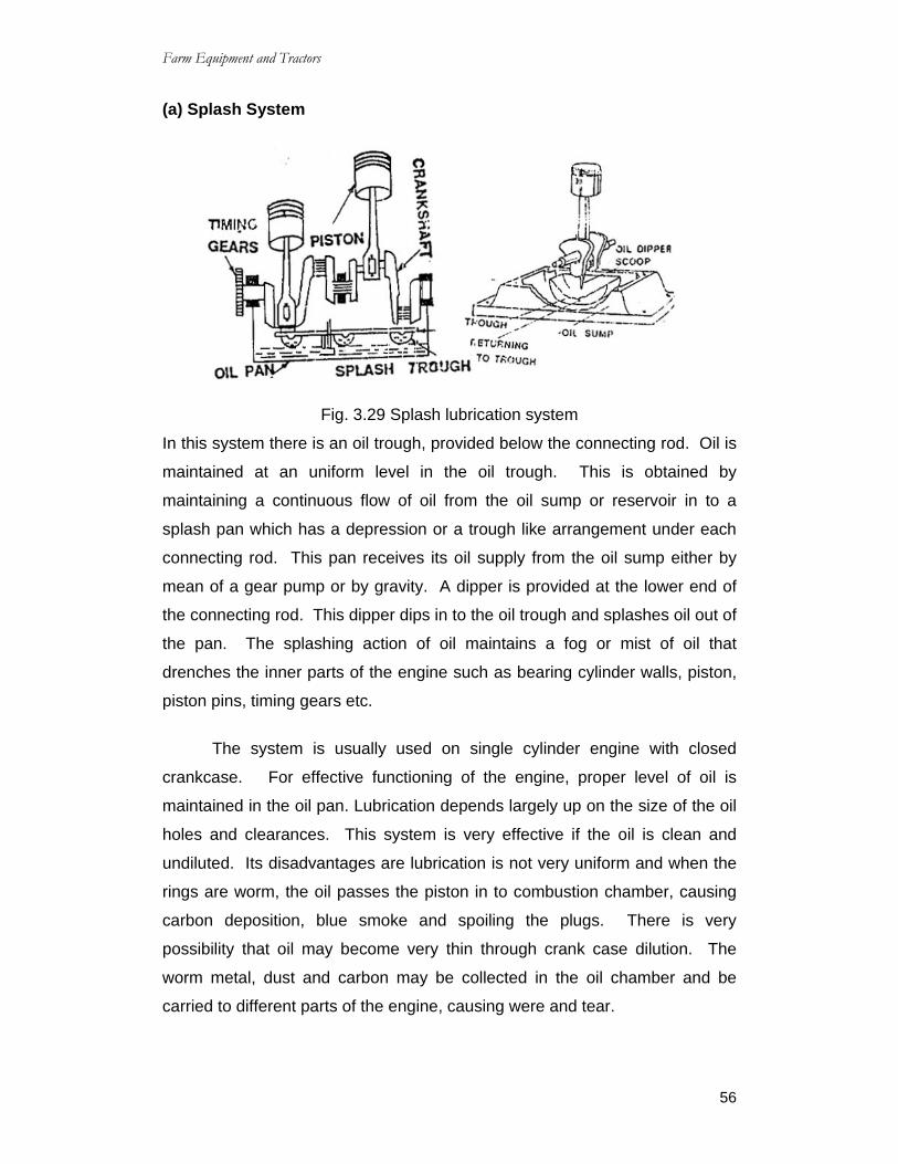
Farm Equipment and Tractors
56
(a) Splash System
Fig. 3.29 Splash lubrication system
In this system there is an oil trough, provided below the connecting rod. Oil is
maintained at an uniform level in the oil trough. This is obtained by
maintaining a continuous flow of oil from the oil sump or reservoir in to a
splash pan which has a depression or a trough like arrangement under each
connecting rod. This pan receives its oil supply from the oil sump either by
mean of a gear pump or by gravity. A dipper is provided at the lower end of
the connecting rod. This dipper dips in to the oil trough and splashes oil out of
the pan. The splashing action of oil maintains a fog or mist of oil that
drenches the inner parts of the engine such as bearing cylinder walls, piston,
piston pins, timing gears etc.
The system is usually used on single cylinder engine with closed
crankcase. For effective functioning of the engine, proper level of oil is
maintained in the oil pan. Lubrication depends largely up on the size of the oil
holes and clearances. This system is very effective if the oil is clean and
undiluted. Its disadvantages are lubrication is not very uniform and when the
rings are worm, the oil passes the piston in to combustion chamber, causing
carbon deposition, blue smoke and spoiling the plugs. There is very
possibility that oil may become very thin through crank case dilution. The
worm metal, dust and carbon may be collected in the oil chamber and be
carried to different parts of the engine, causing were and tear.

Farm Equipment and Tractors
57
(ii) Forced feed system In this system the oil is pumped directly to the crankshaft, connecting
rod, piston pin, timing gears and camshaft of the engine through suitable
paths of oil. Usually the oil first enters the main gallery, Which may be a pipe
or a channel in the crankcase casting. From this pipe, it goes to each of the
main bearings through holes. From main bearings, it goes to big end
bearings of connecting rod through drilled holes in the crankshaft. From
there, it goes to lubricate the walls, pistons and rings. There is separate oil
gallery to lubricate timing gears. Lubricating oil pump is a positive
displacement pump usually gears type or vane type. The oil also goes to
valve steam and rocker arm shaft under pressure through an oil gallery. The
excess oil comes back from the cylinder head to the crankcase. The pump
discharges oil in to pipes oil galleries or ducts, leading to different parts of the
engine. This system is commonly used on high speed multi cylinder engine in
tractors trucks and automobiles.
(iii) Combination of splash and Forced feed system In this system, the engine component which are subjected to very
heavy load are lubricated under forced pressure, such as main bearing
connecting rod bearing and camshaft bearing. The rest of the parts like
cylinder liners, cans, tappets etc, are lubricated by splashed oil.
Fig. 3.30
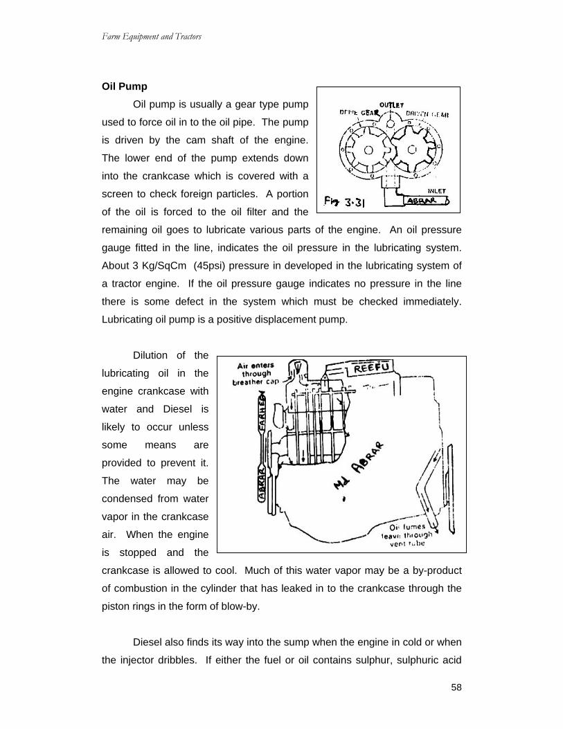
Farm Equipment and Tractors
58
Oil Pump Oil pump is usually a gear type pump
used to force oil in to the oil pipe. The pump
is driven by the cam shaft of the engine.
The lower end of the pump extends down
into the crankcase which is covered with a
screen to check foreign particles. A portion
of the oil is forced to the oil filter and the
remaining oil goes to lubricate various parts of the engine. An oil pressure
gauge fitted in the line, indicates the oil pressure in the lubricating system.
About 3 Kg/SqCm (45psi) pressure in developed in the lubricating system of
a tractor engine. If the oil pressure gauge indicates no pressure in the line
there is some defect in the system which must be checked immediately.
Lubricating oil pump is a positive displacement pump.
Dilution of the
lubricating oil in the
engine crankcase with
water and Diesel is
likely to occur unless
some means are
provided to prevent it.
The water may be
condensed from water
vapor in the crankcase
air. When the engine
is stopped and the
crankcase is allowed to cool. Much of this water vapor may be a by-product
of combustion in the cylinder that has leaked in to the crankcase through the
piston rings in the form of blow-by.
Diesel also finds its way into the sump when the engine in cold or when
the injector dribbles. If either the fuel or oil contains sulphur, sulphuric acid
Farm Equipment and Tractors
59
may be formed by such dilution. This acid may be formed by such dilution.
This acid caused corrosion of the crank case metals as does water, if either or
both are allowed by to collect and remain in the crankcase.
Crankcase ventilation is employed to minimize this dilution. It involves
the passing of a constant stream of air through the crankcase, which picks up
and carriers away most of the fuel vapor before they can condense and dilute
the oil.
The ventilation system may be open system or closed system. In the
open type a bent tube is connected to the crankcase extended in open air.
The flow of air at the end of the tube creates a vacuum which draws the
vapors from the crankcase. The air is drawn in to the crankcase through a
breather cap which is fitted to the oil filler cap.
In the closed system, the air enters through the oil filler cap(Breather).
Circulates through the crank case and then passes away through a
connecting tube in to the intake manifold. From there it reaches the
combustion chamber and then in to the exhaust.
QUESTIONS Short Answer Type Questions
1) What are the main parts of fuel system of diesel engine?
2) What are the main parts of fuel injection pump?
3) What is the function of fuel nozzle?
Essay Type Questions 1) Explain briefly about Fuel fiter used in diesel engine?
2) Explain briefly about Fuel injection pump used in diesel engine?

Farm Equipment and Tractors
60
CHAPTER – 4 TRANSMISSION
4.0 Introduction Transmission is a speed reducing mechanism, equipped with several
gears. It may be called a sequence of gears and shafts, through which the
engine power is transmitted to the tractor wheels. The system consists of
various devices, that cause forward and back word movement of tractor to suit
different field conditions. The complete path of power from the engine to the
wheels is called power train.
Fig 4.1 Power transmission system
Function of power transmission system (i) To transmit power from the engine to the rear wheels of the tractor.
(ii) To make reduced speed available, to rear wheels of the tractor.
(iii) To alter the ratio of wheel speed and engine speed in order to suit the field
conditions.
(iv) To transmit power through right angle drive, because the crank shaft and rear
axle are normally at right angles to each other.
The power transmission system consists of:
(a) Clutch; (b) Transmission gears; (c) Differential: (d) Final drive (e) Rear axle
(f) Rear wheels.

Farm Equipment and Tractors
61
Combination of all these components is responsible for transmission of
power.
4.1 Clutch The clutch is fitted in between engine and gear box. Clutch is a device,
used to connect and disconnect the tractor engine from the transmission
gears and drive wheels. Clutch transmits power by means of friction between
driving members and driven members.
4.11 Necessity of clutch in a tractor Clutch in a tractor is essential for the following reasons:
(i) Engine needs cranking by any suitable device for easy cranking, the engine is
disconnected from the rest of the transmission unit by a suitable clutch. After
starting the engine, the clutch is engaged to transmit power from the engine to
the gear box.
(ii) In order to change the gears, the gear box must be kept free from the engine
power, other wise the gear teeth will be damaged and engagement of gear
will not be perfect. This work is done by a clutch.
(iii) When the belt pulley of the tractor works in the field it needs to be stopped
without stopping the engine. This is done by a clutch.
4.12 Essential features of a good clutch (i) It should have good ability of taking load with out dragging and chattering.
(ii) It should have higher capacity to transmit maximum power with out slipping.
(iii) Friction surface should be highly resistant to heat effect.
(iv) The control by hand lever or pedal lever should be easy.
4.1.3 Types of Clutches Clutches are mainly of three types.
(1) Friction clutch; (2) Dog clutch: and (3) Fluid coupling clutch.
Friction clutch is the most popular in four-wheel tractors, fluid clutch is
also used in some factors these days, dog clutch is mostly used in power
tillers. Friction clutch may be subdivided into three classes: (a) single plate

Farm Equipment and Tractors
62
clutch or single disc clutch; (b) Multi plate clutch or multiple disc clutch and (c)
cone clutch.
4.1.4 Friction Clutch Friction clutch produces gripping action, by utilizing the frictional force
between two surfaces. These surfaces are pressed together to transmission
power.
While starting the engine, the clutch pedal is depressed. After the start
of the engine, the clutch pedal is slowly released to increase the pressure
gradually on frictional surfaces until there is no slip. Thus the driven plate is
gripped firmly to the driving plate. Transmission of power depends upon the
kind of material used for the friction members and intensity of the force,
pressing them together.
4.1.5 Single Plate Clutch This may be called single
disc clutch. It consists of: (1)
pressure plate (2) clutch plate (3)
springs and (4) Release fingers.
There is only one clutch
plate in this type. The clutch plate
is pressed against the fly wheel of
the engine by means of spring loaded pressure plate. When the pedal of the
clutch is depressed, the pressure plate is pushed back by the release fingers.
This releases the pressure from the clutch plate. Then the clutch plate stops
rotating but the flywheel continues to rotate. When the clutch pedal is
released, the pressure plate forces the clutch plate against flywheel to cause
the clutch plate and the flywheel to turn together as one unit. Thus the power
of the engine goes to the gear box for on ward transmission to rear wheels.
4.1.6 Multi Plate Clutch This may be called multiple disc clutch. It has got a number of thin
metal plates, arranged alternately to work as driving and driven numbers.
Fig. 4.2 Single Plate clutch

Farm Equipment and Tractors
63
One set is attached to the flywheel and the
other set is attached to the clutch shaft. If
the plates are pressed together, the clutch is
said to be engaged and the power is
transmitted from the engine to the gear box
for onward transmission to the rear wheels.
This pressure is obtained by a set heavy
springs, fitted together in a housing.
Engagement and disengagement of
this type of clutch is very smooth due to
larger surface area of friction members.
Dog Clutch: It is a simple clutch having square jaws which are used to drive
a shaft in either direction. It is mostly used in power tillers.
4.1.7 Fluid Coupling Clutch Fluid coupling consists of a
driving member and a driven member.
An impeller with radial vanes constitutes
the driving member and runner with
redial vanes constitutes the driven
member. The entire unit is housed in a
suitable casing. A coupler is mounted
on the engine crankshaft and is ¾ th filled with suitable oil. A spring-loaded
sealing ring is provided to make the driven shaft oil tight. At the rotation of the
crankshaft, the oil is thrown out by centrifugal force from the center to the
outer edge of the impeller, increasing the velocity and the energy of the oil. It
then enters the runner wanes at the outer portion and flows towards the
center, causing rotation to the runner unit. As long as impeller and runner
rotate at different speeds, the oil continues to circulate uniformly but when the
impeller and runner start running at same speed, the circulation of oil stops.
The coupling does not increase the applied torque but only transmits the
torque in an uniform manner.
Fig. 4.3. Multiplate clutch
Fig. 4.4. Fluid coupling clutch

Farm Equipment and Tractors
64
The main features of fluid coupling are:
(i) Absorption of shock and vibration;
(ii) Smooth starting and
(iii) Easy operation.
4.2 Clutch fault finding and causes 1. Slippage of clutch
(i) Wrong clutch play adjustment.
(ii) Weak or broken pressure plate springs.
(iii) Worm out or broken clutch facings.
(iv) Rusty or jammed pressure plates.
(v) Oil in clutch facing.
(vi) Rusty or jammed clutch operating linkages. (vii) Worn out facing of pressure plate or flywheel. 2. Clutch Grabbing
(i) Oily clutch facing.
(ii) Worm nut clutch plate hub or clutch shaft.
(iii) Jammed or sticky pressure plate.
(iv) Loose or broken engine foundation.
3. Noisy Clutch (i) Oily clutch facing.
(ii) Clutch pedal wrongly adjusted.
(iii) Clutch release lever tight on pin or ball.
(iv) Bent or warped pressure plate.
(v) Worn out clutch shaft.
(vi) Excessive back-lash in gear box.
4. Failure of clutch (i) Broken pressure plate springs.
(ii) Worm out clutch plates.
(iii) Poor or wrong clutch play adjustment.
(iv) Clutch finger height improper.
(v) Warped pressure plate.

Farm Equipment and Tractors
65
4.3 Transmission Box
Introduction Transmission box in tractor is made up of following assemblies; Gear
box, differential and torque converter, power take drives in assemblies are
housed in one box. In a simple layout of tractor power flow shown in fig.4.5.
Fig 4.5 Transmission Box Gear box It is a unit fitted after clutch and is provided so that driver can increase
the driving torque to cope up with field and load conditions. We also know
more power is required to set the tractor in motion, when it has started rolling
less is required; more over for reversing the tractor we also require a set of
gears, as the engine runs only in one direction.
Gear A tractor engine runs at high speed, but the rear wheel of the tractor
requires power to low speed and high torque. That’s why it becomes essential
to reduce the engine speed and increase the torque available at the rear
wheels of the tractor because,
2∏NT HP = ----------- 4500

Farm Equipment and Tractors
66
Where ‘T’ is torque (Kg.m) and ‘N’ is speed rev/min. If the engine hp is
constant, it is obvious that for higher
torque at wheels, low speed is required
and vise versa. So that gear box is
fitted between engine and rear wheel
for variable torque and speed. This is
done by suitable design of gear and
shafts fig 4.6.
Speed varies according to the field requirements and so a number of
gear ratios are provided to suit the varying conditions. Gears are usually
made of alloy steel. As the tractor has to transmit heavy torque all the time,
best quality lubricants, free from sediments, grit, alkali, moisture, is used for
lubrication purpose. SAE 90 oil is generally recommended for gear box.
Common gears used on tractor are of two types:
(i) Selective sliding type; (ii) Constant mesh type;
(i) Selective sliding type The gear box consists
of: a) gear housing; b) gear
shifting liver: c) main shaft or
input shaft: d) out put shaft and
e) Lay shaft or counter shaft.
A number of gears are
mounted on these shafts. The
main shaft is directly
connected to the clutch and carries gears. The gears are liable to slide. The
gears are shifted with the help of shifting lever and shifting fork.
The gears are shifted along the shaft, to which they are splined to
engage with another gear as and when desired to connect the power train.
The gears are of different diameters having different number of teeth. Speed
is reduced in proportion to the number of teeth provided on the gears.
Fig 4.6 Transmission gears
Fig 4.7 Sliding type gear box

Farm Equipment and Tractors
67
(ii) Constant mesh gear box
Fig 4.8 Constant mesh gear box In constant speed gear box the gears of lay shaft and main shaft are
always in engaged position, it is splinted sleeve which is made to mesh with
gear right or left or kept in middle for neutral position. One simple constant
mesh gear box is shown in fig. Where gear ‘A’ is made on clutch shaft and is
always in mesh with gear ‘B’ of counter shaft, on counter shaft along with gear
‘B’ gear ‘C’ and ‘D’ are also made and revolve with it. When we start the
engine the clutch shaft moves since gear ‘A’ is in mesh with gear ’B’ counter
shaft also moves along with gear C and D, in line with clutch shaft there is
main shaft having gear ‘E’ and ‘F’ mounted free on the shaft with the help of
bush or needle Bearings, gear ‘E’ also keeps of revolving since it is in mesh
with counter shaft gear ‘C’ gear ‘F’ has splined hub and can move to and froe
on splines of main shaft. In between gears ‘A’ and ‘E’ there is splined sleeve
having corresponding teeth cut on both corners. Similarly, corresponding
teeth are also cut on gear ‘E’ and gear ‘A’.
4.4 Differential unit and Final drive
Differential Differential unit is a special arrangement of gears to permit one of the
rear wheels of the tractor to rotate slower of faster then the other. While
turning the tractor on a curved path, the inner wheel has to travel lesser
distance than the outer wheel.

Farm Equipment and Tractors
68
The inner wheel requires lesser power than the outer wheel, this
condition is fulfilled by differential unit, which permits one of the rear wheels of
the tractor to move faster than the other at the turning point. The out put shaft
coming from the gear box is provided with a bevel pinion at the end of the
shaft. The Bevel pinion is in mesh with a large bevel wheel known as crown
wheel. The main functions of grown wheel assembly are:
(i) To transmit power through right angle drive to suit the tractor wheels.
(ii) To reduce the speed of rotation.
The differential unit consists of: (a) Differential casing; (b) Differential
pinions; (c) Crown wheel: (d) Half shaft and (e) Bevel gear.
The differential casing is rigidly attached with the crown wheel and
moves like one unit. Two pinions are provided inside the differential casing,
such that they are carried round by the crown wheel but they are free to rotate
also on their own shaft or stud. There are two or more bevel gears in mesh
with differential pinion. One bevel pinion is at the end of each half shaft,
which goes to the tractor rear wheel. Thus instead of crown wheel being
keyed directly to a solid shaft between the tractor wheels. The drive is taken
back from the indirect route through differential casing, differential pinion and
half shaft of the tractor. When the tractor is moving in a straight line, the
differential pinion do not rotate on the stub shaft but are solid with the
differential casing. They drive the two bevel gears at the same speed and in
the same direction as the casing and the crown wheel.
Each differential pinion can move in two planes simultaneously. When
it is carried round by the casing, it drives the half-shaft in the same direction
but when it is rotated on its own shaft, it drives them in opposite direction, i.e.,
rotation of differential pinion adds motion to one shaft and subtracts motion
from the other shaft.

Farm Equipment and Tractors
69
Differential lock
Differential lock is a device to join both half axles of the tractor so that
even if one wheel is under less resistance, the tractor comes out from the
mud etc, as both wheels move with the same speed and apply equal traction.
Final drive Final drive is a gear reduction unit in the power trains between the
differential and the drive wheels. Final drive transmits the power finally to the
rear axle and the wheels. The tractor rear wheels are not directly attached to
the half shafts but the drive is taken through a pair of spur gears. Each half
shaft terminates in a small gear which meshes with a large gear called bull
gear. The bull gear is mounted on the shaft, carrying the tractor rear wheel.
The device for final speed reduction, suitable for tractor rear wheels in known
as final drive mechanism.
Gear ratio: When two gears have same
number of teeth both run at same speed.
So the gear ratio is 1:1. In fig4.10 see
that a smaller gear ‘A’ having 6 teeth is
driving a bigger gear ‘B’ having 18 teeth
as such smaller gear has to run 3 times
then only bigger gear ‘B’ will make one revolution so the gear ratio will be 18:6
or 3:1. Thus the gear ratio of two gears is their relative speed or the rpm on
which they run.
4.5 Gear box trouble shooting (a) Noisy gear box
(i) Less or no lubricating oil in gear box.
(ii) Gear box or flywheel housing out of alignment with the engine.
(iii) Worn out or broken gear teeth.
(iv) Loose gear on splines or shaft.
(v) Worm out teeth of shifting sleeve.
(vi) Worn out bearings of clutch shaft or main shaft or counter shaft.

Farm Equipment and Tractors
70
(vii) Fork bent.
(viii) Worn out gear shifting mechanism.
(b) Slipping out of gear
(i) Weak spring of fork rod.
(ii) Engine flywheel housing and gear box out of alignment.
(iii) Worn out gear of sleeve or gears.
(iv) Worn out pilot bearing in clutch shaft.
(v) Worn out bearing of clutch shaft, main shaft or counter shaft.
(vi) Worn out or bent fork.
(vii) Worn out rings of synchro mesh unit;
(viii) Too much play in gear shifting mechanism.
(c) Oil leak
(i) Too much of oil in the gear box
(ii) Oil of low viscosity
(iii) Loose top cover or any other cover bolts.
(iv) Cracked housing or top cover.
(v) Worn out rear oil seal.
(vi) Broken gasket.
(vii) Worn out sleeve of release bearing.
(viii) Loose drain plug or filler plug.
4.6 Differential Trouble shooting (a) Noisy Differential
(i) Less lubricating oil in the differential housing.
(ii) Low viscosity oil or use of poor quality oil.
(iii) Wrong adjustment of crown wheel and pinion.
(iv) Worn out or broken teeth of crown wheel or pinion.
(v) Less back lash of crown wheel and pinion teeth.
(vi) Worn out bearing of crown wheel or pinion.
(vii) Crown wheel misaligned on cage.
(viii) Loose star pinion.
(ix) Broken or worn out thrust washers of star pinion or sun pinion.

Farm Equipment and Tractors
71
(b) Tractor does not move when put in gear (i) Broken axle shaft.
(ii) Broken teeth of crown and pinion.
(iii) Broken cross or star pinion.
4.7 Power Take off Shaft (P.T.O Shaft) Power take off shaft usually known as P.T.O shaft. In now-a-days a
standard fitting on all tractors and is used for running rotavator, fertilizer
spreader, duster, sprinkler and many more machines which are stationary
such as: threshes, water pump, portable flour mill etc.
These shafts either run on 540 or 1000 rpm old standard (1938)
specified speed of 540 rpm and number of P.T.O shaft splines was 6 in
number. While the new standard has specified 21 splendid P.T.O shaft
running at 1000 rpm (see fig 4.1.1) with new generation high performance
machine it was necessary for more speed. But we have lots of old tractors
having 540rpm P.T.O shaft while the equipment now available is for 1000rpm.
P.T.O shaft as such most of the tractor manufactures are providing
auxiliary gear box which increases the speed to 1000 rpm having out put shaft
having 6 splines. But never the less after some time 540rpm P.T.O shaft with
6 splines shaft would be eliminated.

Farm Equipment and Tractors
72
QUESTIONS Short Answer Type Questions
1) What is meant by Transmission?
2) What is the use of clutch and where it is fitted?
3) What are the different types of clutches?
4) What is meant by P.T.O shaft and write any two uses of it?
Essay Type Questions 1) Explain briefly about necessity of clutch in a tractor and write any two
essential features of a good clutch?
2) Explain briefly about single plate clutch with the help of neat sketch?
3) Write about fault finding of clutch and their causes?

Farm Equipment and Tractors
73
CHAPTER – 5 STEERING SYSTEM
Fig 5.1 Steering system The system, governing the angular movement of front wheels of a
tractor is called steering system. This system minimizes the efforts of the
operator in turning the front wheel with the application of leverages. The
different components of the system are:
(i) steering wheel; (ii) steering shaft; (iii) steering gear; (iv) pitman arm:
(v) drag link; (vi) steering arm; (vii) tie rod and (viii) king pin. When the operator turns the steering wheel, the motion is transmitted
through the steering shaft to the angular motion of the pit man arm, through a
set of gears. The angular movement of the pit man arm is further transmitted
to the steering arm through the drag link and tie rods. Steering arms are
keyed to the respective kingpins which are integral part of the stub axle on
which wheels are mounted. The movement of the steering arm affects the
angular movement of the front wheel.

Farm Equipment and Tractors
74
In other design, in stead of one pit man arm and drag link, two pit man
arms and drag links are used and the use of tie rod is avoided to connect both
steering arms.
5.1 Types of steering Gear Box The various types of gears normally available on different make of
tractors are:
1. Worm and nut type; 2. Worm and sector type; 3. Worm and roller type;
4. Cam and lever type; 5. Worm and pin type.
5.1.1 Worm and nut type Ford 3600 and MF 1035 tractors are
equipped with this type of steering system.
The steering shaft has square threads
and is supported in self-aligned bearing,
looseness of shaft is adjusted by tightening
or loosening of cushioned rings on steering
outer shaft. On the worm is placed a nut
having square identical threads. This nut is
hinged to sector shaft. On moving steering
shaft nut moves up and down making sector shaft and drop arm move to and
froe.
5.1.2 Worm and sector type steering Escort 3036 and 335 tractors
are fitted with this type of steering
system.
Worms are cut on shaft. This
shaft is supported in the housing with
the help of two bearings one at the top
and the other at the bottom and can
rotate easily. A sector with identical
Fig. 5.2 Worm and nut type
Fig. 5.3 Worm and sector type steering

Farm Equipment and Tractors
75
teeth is held in the sector shaft. Sector shaft rotates the two bronze bushes in
either side of steering housing. On moving the steering wheel worm shaft
along with sector shaft moves resulting in movement of drop arm.
5.1.3 Worm and roller type steering By Elarus tractor is fitted with this type of
steering system.
As a matter of fact it is an improved version of
worm and nut type of steering. In this type steel balls
are placed in nut having semicircular thread. As such
balls run half in the threads cut in worm while other half
Fig. 5.4. Worm and roller type steering
in the recess cut in the nut, balls are fed from one end and return back
through pipe clamped on nut, as such set of balls go on circulating and
minimize friction. The nut in which balls move is hinged to the sector shaft
which runs on bushes fixed in the steering housing. When the worm moves it
takes nut and sector shaft along with it and drop arm moves to and froe.
5.1.4 Cam and Lever type steering
The B-275 tractor is fitted with this type of
steering system.
In this case the worm is held in the
housing with the help of two taper roller bearing,
sector shaft runs in bushed fitted in the housing.
It has lever which runs in the worm. On
revolving the worm shaft along with lever and
sector shafts revolves. Such arrangement is
shown in fig.
5.1.5 Worm and pin type or Working of hydraulic steering
ZF power steering as used in imported Zetor tractor is shown in fig. In
this fig. you will see that piston (4) can go up and down in cylinder (5), piston
Fig. 5.5 Cam and lever type steering

Farm Equipment and Tractors
76
(4) is connected to rocker shaft (7) with the help of connecting rod (6). On top
of the piston a nut (3) is bolted in which steering spindle (1) having threads
work. A thrust bearing (11) is fixed in the body on which the steering spindle
moves freely. When we revolve the steering spindle with the help of steering
wheel due to screwing action, it pulls or pushes the piston, as the case may
be we have already mentioned that the piston is tied up with the rocker shaft
with the help of connecting rod as such the rocker shaft moves to and froe,
with the rocker shaft is tied up drop arm and drag link as such the wheels get
steered.
Fig 5.6 Worm and pin type
Until now the system we have discussed is purely a mechanical system
having worm and nut type steering. To make the steering light it has certain
hydraulic parts also.
Let us study these On steering spindle is fixed sleeve (8) which moves to and froe through
slinght angle, when steering shaft is moved. This sleeve works as an
hydraculic valve, and when it moves in one direction, it connects the oil
pressure to get into the pressure chamber ‘A’. At the same time the oil
trapped in chamber ‘B’ is allowed to escape through discharge post. When
the hydraulic oil enters the pressure chamber ’A’, pressure gets built up there
and this pressure causes the piston to move up. Thus helping the driver to
steer the tractor with less effort. Similarly when steering shaft is moved in the
other direction, control sleeve connects pressure chamber ‘B’ with the

Farm Equipment and Tractors
77
pressure line and at the same time allowing the hydraulic oil from chamber ‘A’
to escape through drainpipe. The hydraulic pressure in chamber ‘B’ pushes
the piston down.
5.2 Front Axle
Front axle is the unit on which front wheel is mounted. This wheel is an
idler wheel by which tractor is steered in various directions. The axle is a rigid
tubular or I-section steel construction pivoted at the center. The I-section
type front axles are three-piece axle shown in fig. Two side pieces are bolted
Fig. 5.7

Farm Equipment and Tractors
78
to the middle piece with the help of two bolts through a set of holes, to get
desired track width. Some of the tractors (viz. Ford, M1035 etc) are provided
with radius rods connected on both sides of the axle with the other ends
connected to the transmission housing. These radius rods provide rigidly as
well as limit radial movement to the axle. Both the outer ends of the axle have
provisions for holding kingpins. These kingpins are supported in the axle
housing with the help of metallic bushes. A thrust bearing is normally placed
on the lower side of the kingpin.
5.2.1 Front Axle Adjustment (a) Track-width adjustment
Depending upon the requirement of the
tract width, the axles can be extended on both
sides. Fig 5-8 shows the adjustment of the
track width from minimum to maximum for ford
tractor. Whenever the track width is adjusted,
the wheel toe-in must also be checked and
corrected.
(b) Toe-in Adjustment The front wheels are slightly drawn
in at the front side in such away that the
distance between the front side is slightly
less than the backside. The difference is
known as toe-in and varies in the range of
4±2mm. To get the desired toe-in, the
procedure followed is as under:
1. Bring the tractor on a levelled ground with front wheels in straight- ahead
position. This can be done by moving the steering wheel from one extreme to
another extreme position and then bringing it in the middle of its total
revolution.
2. Mark the center point on the width of each tire and measure the distance
between both the front types at the front and rear sides. For desired results,
Fig. 5.8. Track width adjustment
Fig. 5.8. Toe in adjustment

Farm Equipment and Tractors
79
the rods or drag-link ends are slacned and the rods are rotated clock wise or
anti clock wise to increase or decrease the toe-in. Ensure that the distance of
both types are equal from the center of the axle. Similarly, the rear side of
both tires should be equal from the center of the axle, but more than the
distance at the front side. To achieve equal movement, both the drag links
should be rotated equally.
(c) Caster Angle It is the angle between the center line of the king pin of the tractor and
the vertical line.
(d) Camber Angle It is the angle between the center line of the type and the vertical line.
5.3 Brakes Brake is used to stop or slow down the motion of a tractor. It is mounted
on the driving axle and operated by two independent pedals. Each pedal can
be operated independently to assist the turning of tractor during the field work
or locked together by means of a lock.
Principle of Operation Brake works on the principle of friction. When a moving element is
brought into contact with a stationary element, the motion of the moving
element is affected. This is the due to frictional force which acts in opposite
direction of the motion and converts the kinetic energy into heat energy.
5.3.1 Classification of Brake Brake can be classified as:
(1) Mechanical brake and (2) Hydraulic brake.
Mechanical brake can be; (a) Internal expanding shoe type (b) External
contracting shoe type and (c) Disc type.

Farm Equipment and Tractors
80
(a) Internal Expending shoe type Two brake shoes made of frictional material fitted on the inside of the
brake drum are held away from the drum by means of springs. One end of
each shoe is fulcrumed where as the other is free to move by the action of a
cam which in turn applies force on the shoes. The movement of the cam is
caused by the brake pedal through the linkage. The drum is mounted on the
rear axle where as the shoe assembly is stationary and mounted on the back
plate.
(b) External Contracting shoe type This type of brake system is
normally available on crawler tractors.
The drum mounted on the drive axle is
directly surrounded by the brake band.
When the pedal is depressed, the band
tightens the drum.
(c) Disc brake Two actuating discs have holes drilled in each disc in which steel balls
are placed. When the brake pedal is depressed, the links help to move the
two discs in opposite directions. This brings the steel balls to shallow part of
the holes drilled in the disc. As a result, the two discs are expanded and
braking discs are pressed in between the discs and the stationary housing.
The braking discs are directly mounted on the differential shaft which
ultimately transfers the travelling effect to the differential shaft.
(d) Hydraulic brake
Hydraulic brake system is
based on the principle of Pascal’s
low. The brake fluid which is
usually a mixture of glycerin and
alcohol is filled in the master
cylinder, when the pedal is
depressed, the piston of the master
Fig 5.10 External contracting break shoe
Fig 5.11 Hydraulic break

Farm Equipment and Tractors
81
cylinder is forced into the cylinder and the entire system turns to a pressure
system. Immediately, the piston of the wheel cylinder slides out ward which
moves the brake shoes to stop the rotating drum. When the pedal is
released, the return spring of the master cylinder moves the piston back to its
original pisiton, causing a sudden pressure drop in the line. The retracting
springs of the brake shoe bring them back to their original position. Thus the
piston of the wheel cylinder returns back.
QUESTIONS Short Answer Type Questions
1) What are different components of steering system?
2) What is the use of brakes in a tractor?
3) What is the use of steering system in tractor?
4) What are different types of brakes?
Essay Type Questions 1) Explain briefly about steering system used in tractor?
2) What is the necessity of brake and explain briefly about any one type of
brake?

Farm Equipment and Tractors
82
CHAPTER – 6 HYDRAULIC SYSTEM OF TRACTORS
6.0 Hydraulic System
It is mechanism in a tractor to raise, hold or lower the mounted or semi
mounted equipment by hydraulic means. All tractors are equipped with
hydraulic control system for operating three point hitch or the tractor.
6.1 Working principle of hydraulic system The working principle of hydraulic
system is based on Pascal’s law. This law
states that the pressure applied to an
enclosed fluid is transmitted equally in all
directions. Small force acting on small area
can produce higher force on a surface of larger area.
Working of Hydraulic system A simple hydraulic system consists of a pump which pumps oil to a
hydraulic ran. This pump may be driven from tractors transmission system or
it may be mounted on its engine. This system consists of a cylinder with a
close filling piston like an engine cylinder. As the oil is pumped in to the
closed end of the cylinder, the piston is forced along with it. The movement of
the piston is transmitted to the lower links by means of a cross shaft and lift
rods. A control valve controls the flow of oil and direction it back to the
reservoir. It allows the oil in the cylinder to flow out again when the links are
to be lowered. It also traps the oil in the cylinder when the links are to be held
at any height.
Fig (a,b,c) shows the schematic diagrams of a hydraulic system fitted.
With the following basic components.
(i) Reservoir (ii) Pump (iii) Relief valve (iv) Control valve (v) Cylinder and (vi)
Filter or strainer
(i) Reservoir: It contains sufficient oil to move the piston for lifting the load.
(ii) Pump: It forces the fluid from the reservoir to the cylinder.
Fig. 6.1.

Farm Equipment and Tractors
83
(iii) Relief Valve It protects the system from high pressure. The valve is set for slightly
higher than the working pressure. In case the pressure increases beyond the
Fig. 6.2a
Fig. 6.2b
Fig. 6.2c

Farm Equipment and Tractors
84
working pressure, the relief valve opens allowing the fluid to pass on to the
reservoir. Also, when the piston reaches its extreme position, the relief valve
opens to by pass the oil.
(iv) Control valve
The control valve is used to allow the operator to direct the flow of fluid
either from the pump to the cylinder or from the cylinder to the reservoir.
(v) Cylinder The cylinder converts the hydraulic power to mechanical power, for
doing the various Jobs.
QUESTIONS
Short Answer Type Questions 1) What is the use of hydraulic system?
2) What are the basic components of a simple hydraulic system?
Essay Type Questions 1) Explain briefly about the basic components of a hydraulic system?

Farm Equipment and Tractors
85
CHAPTER – 7 TILLAGE
7.0 Tillage Tillage is the basic operation in farming. It is generally done to create a
favorable condition for seed placement and plant growth. These operations
include ploughing, harrowing and mechanical destruction of weeds and soil
crusts, etc., Hence, the physical manipulation of soil in order to get the
desired condition of the seed bed for sowing and for good growth of plant may
be termed as tillage operation.
7.1 Functions of Tillage (or) objectives of Tillage
a) To obtain a seed bed of good tilth.
b) To add hums and fertility to the soil by covering vegetation and manure.
c) To destroy the weeds and to prevent their growth.
d) To leave the soil in such a condition to that air will circulate freely.
e) To destroy insects and their eggs, larvae and their breeding places.
f) To reduce the soil erosion.
g) To leave the soil in a condition to ratain moisture from the rain.
7.2 Classification of Tillage Tillage is divided into two stages:
(a) Primary Tillage
(b) Secondary Tillage.
a) Primary Tillage The operations performed to open up any cultivable land with a view to
prepare a seed bed for growing crops, are termed as primary tillage.
Primary tillage is done mainly with the implements like mould board
plough, disc plough, Rotary plough, chisel plough and sub soiler.
b) Secondary Tillage Lighter and finer operations performed on the soil after primary tillage,
but before and after seed placement, are termed as secondary tillage.

Farm Equipment and Tractors
86
Secondary tillage implements include harrows (Disc harrow, Toothed harrow),
pulverizes and rollers and cultivators etc.
These operations are generally done on the surface soil of the farm.
Secondary tillage operations do not cause much soil inversion and shifting of
soil from one place to other.
7.3 The main objectives of secondary tillage operations are: a) To pulverize the soil of the seed beds in the field.
b) To destroy grasses and weeds in the field.
c) To cut crop residnes and mix them with top soil of the field; and
d) To break the big clods and to make the field surface uniform and levelled.
Secondary tillage implements may be tractor drum or bullock drawn
implements. Bullock drawn implements include harrows, cultivator, hoes etc.,
7.4 Types of Tillage There are various types of Tillage,
(i). Minimum Tillage: It is the minimum soil manipulation necessary to meet
tillage requirements for crop production. (ii). Strip Tillage: It is a tillage system in which only isolated bands of soil
are tilted. (iii). Rotary Tillage: It is the tillage operations employing rotary action to cut,
break and mix the soil. (iv). Mulch Tillage: It is the preparation of soil in such a way that plant
residues or other mulching materials are specially left on or near the
surface. (v). Combined Tillage: Operations simultaneously utilizing two or more
different types of tillage tools or implements to simplify the number of
operations over a field are called combined tillage. 7.5 Primary Tillage Implements Primary Tillage: Primary tillage is done mainly with ploughs. For ploughing various
types of ploughs are used. These are:
(i) Indigenous plough (or) country plough.
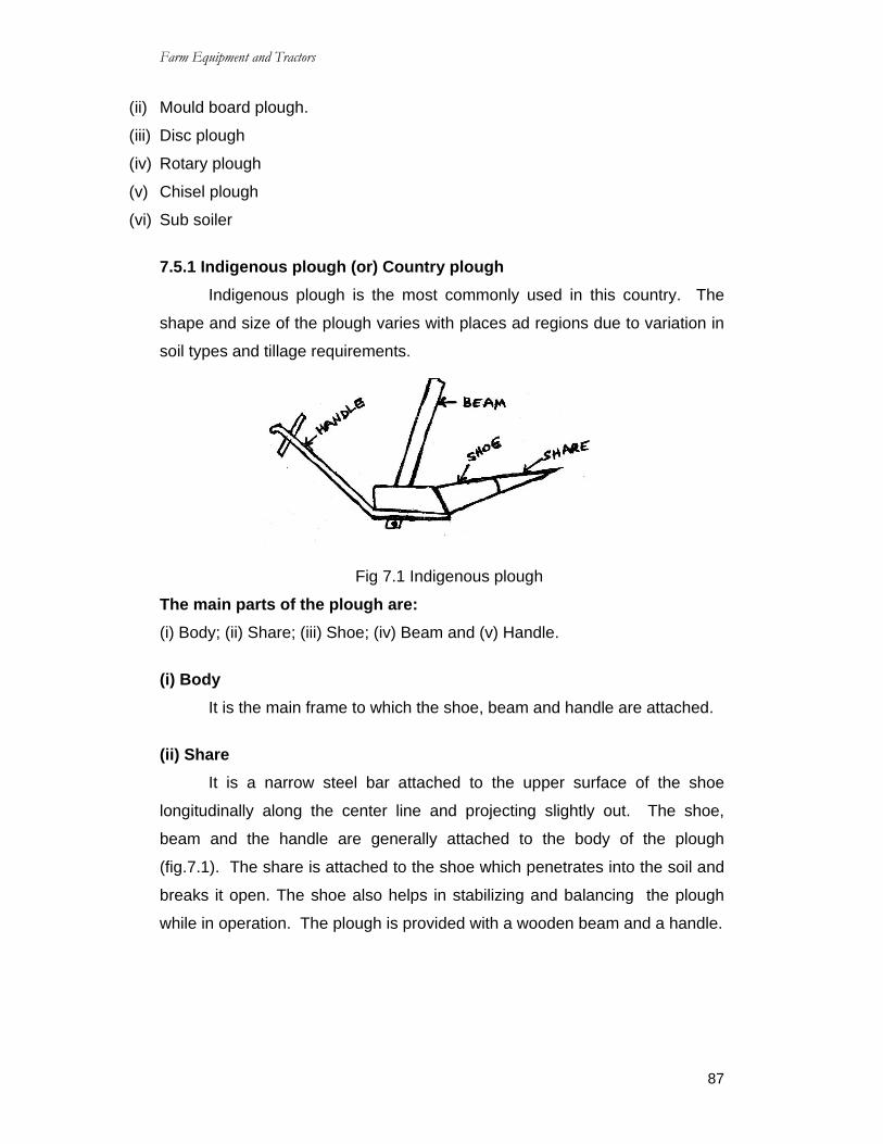
Farm Equipment and Tractors
87
(ii) Mould board plough.
(iii) Disc plough
(iv) Rotary plough
(v) Chisel plough
(vi) Sub soiler
7.5.1 Indigenous plough (or) Country plough Indigenous plough is the most commonly used in this country. The
shape and size of the plough varies with places ad regions due to variation in
soil types and tillage requirements.
Fig 7.1 Indigenous plough
The main parts of the plough are: (i) Body; (ii) Share; (iii) Shoe; (iv) Beam and (v) Handle.
(i) Body It is the main frame to which the shoe, beam and handle are attached.
(ii) Share It is a narrow steel bar attached to the upper surface of the shoe
longitudinally along the center line and projecting slightly out. The shoe,
beam and the handle are generally attached to the body of the plough
(fig.7.1). The share is attached to the shoe which penetrates into the soil and
breaks it open. The shoe also helps in stabilizing and balancing the plough
while in operation. The plough is provided with a wooden beam and a handle.

Farm Equipment and Tractors
88
7.5.2 Mould board plough A mould board plough is very common implement used for primary
tillage operations. This plough performs several functions at a time.
Functions of M.B Plough (a)Share: It is that part of the plough bottom which penetrates in to the soil
and makes a horizontal cut below the surface.
(b)Mould board: It is the curved part which lifts and terms the furrow slice.
(c)Land side: It is the flat plate which bears against and transmits the rear
side lateral thrust of the plough.
(d)Frog: It is the part to which other components of the plough bottom are
attached.
Fig. 7.2. Mould Board Plangh
Fig. 7.3. Components of Mould Board Plough

Farm Equipment and Tractors
89
Details about the parts of Mould board plough Bottom
1. Share
(a) Point of share
(b) Cutting edge of share
(c) Wing of share
(d) Gunnel of share
2. Mould board
3. Land slide
(a) heel of land side
4. Frog
5. Braces
(1) Share: It penetrates in to the soil and makes a horizontal cut below the
soil surface. It is a sharp well polished and pointed component. Different
portions of the share are called by different names such as:
(a) Point of share;(b) cutting edge of share;(c) wing of share;(d) gunnel of
share.
(a) Point of share: It is the forward end of the cutting edge which actually
penetrates into the soil.
(b) Cutting edge of share: It is the front edge of the share which makes
horizontal cut in the soil.
(c) Wing of share: It is the outer end of the cutting edge of share. It supports
the plough bottom.
(d) Gunnel of share: It is the vertical face of the share which slides along the
furrow wall. It takes the side thrust of the soil and supports the plough
bottom against the furrow wall.
Material of share
The shares are made of chilled cast iron or steel. The steel mainly
contains about 0.70 to 0.80% carbon and about 0.50 to 0.80% manganese.
Types of share: Share are of different types such as:
(i) Slip share;(ii) slip nose share;(iii) shin share and (iv) Bar point share.

Farm Equipment and Tractors
90
(i) Slip share This is a common type of
share. The complete share is to be
replaced when worn out.
(ii) Slip nose share In this type, the share point is
provided by a small detachable piece. It
has the advantage that share point can be
replaced as and when required. If the
point is worn out, it can be changed with out replacing the entire share.
(iii) Shin share it is similar to slip share but an
extension is provided to fit by side of
mould board. This prevents mould
board from wearing along its cutting
edge called shin.
(iv) Bar point share A long bar is used which is
pushed forward as the point wears
out. The bar avoids the replacement
of complete share.
2. Mould board: The mould board is that part of the plough which receives the furrow
slice from the share. It lifts, turns, and breaks the furrow slice.
The mould board is of following types:
(i) Stubble Bottom; (ii) General Purpose Bottom; (iii) High speed Bottom;
(iv) Slatter Bottom; (v) Breaker Bottom.

Farm Equipment and Tractors
91
(i) Stubble Bottom It is short and has an abrupt curvature. It
turns the furrow slice quickly and provides
maximum granulation. It is used for ploughing
stubble land and is not suitable for high speed
ploughing.
(ii) General Purpose Bottom It has longer mould board with less
curvature than stubble bottom. It turns soil
less and raptly and may be used in heavy soil,
stubble land.
(iii) High Speed Bottom It has slightly less curvature in the
upper part of the mould board than the
general purpose bottom. Thus provides
less twisting action.
(iv) Slatter Bottom It is a mould board whose surface
is made of slats placed along the length
of the mould board, so that there are
gaps between the slats. This type of
mould board is often used, where the
soil is sticky.
(v) Breaker Bottom It is a long mould board with
gentle curvature, which lifts and invents
the unbroken furrow slice. It is used in
through soil of grasses. It turns over
thickly covered soil. It does not pulverize
soil well. It is used for ploughing heavy
soil.

Farm Equipment and Tractors
92
3. Land slide It is a long flat metal piece which absorbs the side force created when
the furrow is turned. It slides along the face of furrow wall. It also helps to
steady the plough while in operation. It can have removable heel at the rear
and is made of one piece. Land slides are usually made of cast iron or solid
steel.
4. Frog All the working parts are attached to frog and it is made of steel,
usually this does not get damaged but in case of accident, if it gets damaged
it cannot be set right because of its odd shape. Hence it has to be replaced
with the new one.
Accessories of Mould Board Plough There are few accessories necessary for ploughs such as: (a) Jointer;
b) Coulter; c) Gang wheel; d) Land Wheel and; e) Furrow wheel.
(a) Jointer: It is a small irregular piece of metal having a shape similar to an
ordinary plough bottom. It’s function is to move the trash and roots from this
strip towards the main furrow in such a manner as to ensure complete
coverage by the flow bottom.
(b) Coulter: Coulters are used to turn under the long and heavy trash. It cuts
trash into shorter length. Thus plough can cover better. It is used in tractor
drawn ploughs only. There are various types of coulters which are classified
as under:
(i) Sliding type knife coulter and (ii) Rolling type disc coulter.
(i) Sliding type Knife Coulter: It is a stationary knife fixed down ward in a
vertical position on the beam. The knife does not roll over the ground but
slides on the ground. The knife may be of different shapes and sizes. (ii) Rolling type disc coulter: It is a round steel disk having sharp edges,
sometimes it has notched edges also shown in fig. The rolling coulters
perform the following functions:

Farm Equipment and Tractors
93
1. It cuts furrow slice edge levers,
cleans furrow walls.
2. It cuts the trash over the surface of
the field for better coverage by the
furrow slice
3. It reduces plough draft.
4. It keeps the plough clean from
clogging.
(c) Gange wheel
It is also called as Beam wheel. These are attached to the end of the
beam near Clovis to control the depth of ploughing. This is very necessary
where uniform depth of ploughing is desired through out the field.
(d) Land Wheel
It is the wheel of the plough which runs on the unplughed land.
(e) Furrow wheel
Furrow wheel is further divided into two groups.
(i) Front furrow wheel and (ii) Rear furrow wheel.
(i) Front furrow wheel: It is the front wheel of the plough which runs in the
furrow. (ii) Rear furrow wheel: It is the rear wheel of the plough which runs in the
furrow. Adjustment of Mould board plough For proper penetration and efficient work by the mould board plough,
some clearance (0.3 to 0.5m) is provided in the plough. This clearance is
called suction of plough. Suction in mould board plough is of two types:
(a) Vertical suction and; (b) Horizontal suction.
(a) Vertical suction or Vertical
clearance It is the maximum clearance
under the landslide and the horizontal
Fig. 7.6 Notched edged rolling coulter
Fig. 7.7. Vertical suction M.B. Plough

Farm Equipment and Tractors
94
surface when the plough is resting on a horizontal surface in the working
position. It is the vertical distance from the ground, measured at the joining
point of share and land side. It helps the plough to penetrate into the soil to a
proper depth. This clearance varies according to the size of the plough.
(b) Horizontal suction (Horizontal
Clearance) It is the maximum clearance
between the inside and a horizontal
plane touching point of share at its
gunnel side and heal of landslide. This suction helps the plough to cut the
proper width of furrow slice. This clearance, various according to the size of
the plough. It is also known as side clearance.
7.5.3 Disc Plough It is a plough, which cuts, turns and in some cases breaks furrow slice
by means of separately mounted large steel discs. A disc plough is designed
with a view to reduce friction by making a rolling plough bottom instead of
sliding plough bottom. A disc plough works well in the conditions where mould
board plough does not work satisfactory.
Advantages of disc plough 1. A disc plough can be forced to penetrate into the soil which is too hard and
dry for working with a mould board plough.
2. It works well in sticky soil in which a mould board plough does not work.
3. It is more useful for deep ploughing.
4. It can be used safely in stony and stumpy soil without much danger of
breakage.
5. A disc plough works well even after a considerable part of the disc is worn
off in abrasive soil.
6. It works in loose soil also with out much clogging.
Disadvantages of Disc Plough 1. It is not suitable for covering surface trash and weeds as effectively as
mould board plough does.

Farm Equipment and Tractors
95
2. Comparatively, the disc plough leaves the soil in rough and more coldly
condition than that of mould board plough.
3. Disc plough is much heavier them mould board plough for equal 7.5.4
adjustments of standared Dis plough and vertical disc plough capacities.
(a) Standarded disc plough adjustments (i) Disc angle It is the angle between the direction of
travel and the plane of the disc. It is usually kept
between 42 to 45o for minimum draft requirement.
Increasing the disc angle will result in increased
width of cut and draft. A little adjustment in disc
angle is possible by rotating cross draft of the
plough.
(ii) Adjustment of Tilt angle It is the angle between the vertical plane and
the plane of the disc. It is usually between 15 to
25o penetration is improved by decreasing tilt angle
which however, reduces throw of soil.
(b) Vertical Disc Plough adjustments (i) Leveling adjustment
Proper leveling of a vertical disc plough is essential to obtain a uniform
cut and seeding depth, to prevent ridging and to make the plough trail
correctly.
The levelling adjustment is usually made by means of a levelling screw
at the front of the plough frame. When the discs are in raised position, the
front discs will normally be higher than the rear ones.
(ii) Hitching adjustment Selected a level, uniform part of the field and make a cut with the
plough at the desired working depth, using appropriate width of cut.
Fig. 7.9a
Fig. 7.9b

Farm Equipment and Tractors
96
Pull the plough into position with the front wheel in the furrow,
regardless of the position of tractor wheels, make a short run at the normal
working speed and depth.
QUESTIONS
Short Answer Type Questions 1. What is meant by Tillage?
2. What are the primary Tillage equipment's?
3. What are the secondary Tillage equipment's?
Essay Type Questions 1. What are the functions and objectives of Tillage?
2. Explain briefly about indigenous or country plough?
3. Explain briefly about the parts of mould board plough?
4. What are the advantages and disadvantages of disc plough?

Farm Equipment and Tractors
97
CHAPTER – 8 SECONDARY TILLAGE IMPLEMENTS
8.0 Secondary tillage implements The implements used for preparing the soil by smoothing packing the
soil and killing weeds which are called secondary tillage implements.
8.1 Types of secondary tillage implements
Some of the important implements covered under secondary tillage
equipment’s are:
1. Harrows
(A) Disk arrows trailing type / mounted type
(i) Single action (ii) Double action (iii) offset type
(B) Toothed harrow
(i) Spike tooth (ii) Spring tooth
2. Pulverizers and rollers
3. Cultivators.
8.1.1 Harrows
Harrow is an implement used to level the ground break the clods, stir
the soil and destroy the weeds. There are several type of harrows used in
India, such as:
(1) Disc harrow; (2) spring tooth harrow; (3) spike tooth harrow; (4) Blade
harrow (Bakhar); (5) Guntaka; (6) Triangular harrow;(7) Bodela (zig-zig
harrow; (9) Bindha: (10) Other harrows.
1. Disc Harrows
The disc harrow, showing the principle of attrition of the angle of the
gangs of discs.
Fig. 8.1 Disc harrows

Farm Equipment and Tractors
98
These comprise a number of sets or gangs of concave discs which can
be set at a variable angle to direction of travel. Disc harrows are best suited
for lands having stones or stumps, because discs can roll over obstructions.
Uses of Disc harrows (i) Pulverize soil lumps
(ii) Mulch the soil surface
(iii) Firm soil underneath to provide a smooth, uniform seed bed;
(iv) Close air pockets
(v) Incorporate chemicals
(vi) Control weeds and
(vii) Cover broad cast seeds.
8.1.2 Spike Tooth Harrow A spike tooth harrow is
also known as peg tooth or
smoothening harrow. It is used
to smooth seedbed, break soft
clods, kill small weeds as they
Fig. 8.2. Spike toot harrow
emerge from soil, close air pockets in the soil, loosen and aerate soil and
break rain cursed soil for bast emergence of seedlings.
The spike tooth harrows are available either as an animals drawn or
tractors drawn types. The working depth of this kind of harrow is generally
5Cms.
8.1.3 Spring tooth (or) spring Tine harrow It is a harrow with tough flexible teeth suitable to work in hard and
stony soils. Spring tooth harrow is fitted with springs, having loops of elliptical
shape. It gives a spring action in working condition. It is best suited for hard
and stony ground. It is used in the soil where obstructions like stones, roots
and weeds are hidden below the ground surface. It pulverizes the soil and
helps in killing weeds.

Farm Equipment and Tractors
99
8.1.4 Blade Harrow (Bakhar) The blade harrow is an animal
drawn implements popularly known as
‘BAKHAR’. It is a common type of harrow
used by Indian farmer. The primary
action of this implement is to pulverize
soils and create soil mulch. It may be
used to chisel out the uncut soil left after
ploughing by indigenous plough.
8.1.5 Guntaka It is an improved type of blade harrow. The functions of Guntaka are
same as that of Bakhar.
8.1.6 Triangular harrow It is a spike tooth harrow having a triangular frame. The spikes or legs
are rigidly fixed on the frame. It is an animal drawn implement which is used
to break soil clods, stir the soil and uproot the weeds.
Fig. 8.3
Fig. 8.4 Blade harrow
Fig. 8.5 Guntaka

Farm Equipment and Tractors
100
8.1.7 Bodela It is twin blade harrow used in the
southern region of India.
8.1.8 Bindha It is a spike tooth harrow of local
make used in a particular region.
8.1.9. Zig-Zag harrow It is a spike tooth harrow
with a zig-zag frame and teeth
attached at the junctions of the
frame members.
8.2 Adjustment for Depth of Operation 8.2.1 Spike Tooth harrow adjustments
The depth of operation and aggressiveness of spike tooth harrow are
controlled by changing tooth angle. The tooth angle is changed using a lever
and quadrant in small size but hydraulic control in large size harrows.
The tooth position can be controlled from vertical to horizontal. In order
to provide maximum soil agitation and clod breakage, the teeth are kept
vertical. However, draft requirement is maximum at this setting.
8.2.2 Spring Tine harrow adjustments The depth of penetration in this type of harrow is changed by adjusting
the angle of tine as it enters the grounds and also by raising or lowering
runners under each section.
The angle of tine is controlled by a lever and Quadrant in small size but
hydraulic control in large size harrows.
Fig. 8.6. Triangular harrow
Fig. 8.7. Triangular harrow

Farm Equipment and Tractors
101
8.3 Cultivators Cultivation usually refers to the tillage operation of manipulating the soil
after the seeds is planted or the seedlings have emerged.
Cultivators can be of following types:
(i) Disc cultivators (ii) Rotary cultivators (iii) Tine cultivators.
(i) Disc Cultivator: It is a cultivator fitted with disc.
(ii) Rotary Cultivator: It is a cultivators with tines of blades mounted on a
power driven horizontal shaft.
(iii) Tine Cultivator: It is a cultivators fitted with tines having shovels.
The cultivators stirs the soil and breaks the clods. The tines fitted on
the frame of the cultivator, cumb the soil deeply in field. A cultivator performs
functions intermediate between those of plough and the harrow. A mounted
cultivator is shown in fig. Destruction of weeds is the primary function of a
cultivator.
The following are the few important function performed by a cultivator:
(a) Inter culture the fields.
(b) Destroy the weeds in the fields.
(c) Aerate the soil for proper growth of crops.
(d) Conserve moisture by preparing mulch on the surface.
(e) Sows seeds when it is provided with sowing attachments.
(f) Prevents, surface evaporation and encourage rapid infiltration of rain water
into the soil.
Fig. 8.8. Mounted cultivator

Farm Equipment and Tractors
102
Cold crushers and Levelers (1) Cold crushers
These implements are used immediately after ploughing or harrowing if
the land is to be prepared for seeding. The main purpose of operating these
implements is, to crush, grind and tear the unevenly ploughed soil to produce
a smooth, well packed seed bed. It also reduces evaporation losses from the
land surface. While operating these implements if hard clods are met, they
will be forced down in to the soil if they are not crushed. Clods are not at all
desirable in the field. They cause obstruction to the penetration of furrow
openers of the seed drill, besides not allowing intimate contact between the
seeds and the soil, which is essential for germination, they are generally
formed in clay soil. If the soil is ploughed under too wet condition. The best
way of controlling clods is not to allow them to be formed in the field.
The most common clode crusher is pata or patela which is generally a
rectangular section of long wooden log provided with two steel rings for
hitching. The length of the patela varies depending on whether one or two
pairs of bullocks are employed to pull it. While operating the patala, the
operators ride on in to add more weight. In some parts of country bamboo
ladders made of two or three bamboos are also called as patela. Such patela
is comparatively cheaper in the initial cost, but does not last more than two
years. Tractor drawn indigenous clod crushes are made of angle iron frame
properly braced.
The use of rollers as clod crusher is particularly practiced in dry farming
areas. The usual material used in their construction is wood or stone or
concrete. Some times a seat is provided on the top for the operator.
(ii) Levelers In irrigated areas land leveling is an essential operation for farming.
Levelled fields receive uniform penetration of irrigation water with high
efficiency. The possibility of water logging and soil erosion is reduced
considerably. The entire levelled field becomes ready to receive timely
agricultural operations like ploughing. Seeding and inter culturing. Smooth
field also facilitate the operation of field equipment and are very important for

Farm Equipment and Tractors
103
mechanical harvesters. Land leveling usually done in the slack season when
the field is free form crops and the men and bullocks are idle.
Wooden logs or planks are
the most common types of field
levelers used by farmers. They
are operated in ploughed land to
collect loose soil from the high
spots and to dump it into
depression. While operating in the field, the levelers is raised from the rear to
take more cut and then it is tilled upside down to fill up the low spot else
where. The other improved type of land levelers which is used on the large
farms is called the leveling karaha or scaper (or) soil scoop shown in
fig.8.9.
Soil scoop is used in excavating ditches, cleaning drains and moving
soil over distances. It consists of (I) Blade (ii) Soil trough (iii) Hitching loop and
(iv) Handle.
(i) Blade: Blade is made of high carbon steel. The angle of the cutting blade
varies from 12o to 15o only. The blade is riveted or bolted to the soil
trough.
(ii) Soil trough: It is made of miled steel sheet. It has two handle holders
when wooden handles are to be inserted.
(iii) Hitching Loop: Two ends of the loop are fitted to the sides of the soil
trough. The loop is made of mild steel round.
(iv) Handle: There are two handles made of timber or mild steel flat.
8.0 Bund Former
It is used for making bunds or ridges by collecting the soil. Bunds are
required to hold water in the soil, there by conserve moisture and prevent run
off. The size of the bund former is determined by measuring the maximum
horizontal boards. Bund farmer consists of
(i) Forming board; (ii) Beam; (iii) Handle.
Fig. 8.9. Soil scoop

Farm Equipment and Tractors
104
QUESTIONS
Essay Type Questions
1. Explain briefly about disc harrow and mention some of its uses?
2. Explain Blade harrow with the help of neat sketch?
3. Write few important functions performed by a cultivator?

Farm Equipment and Tractors
105
9. SEEDING MACHINERY 9.0 Seeding or Sowing: Seeding or sowing is an art of placing seeds in the soil to have good
germination in the field. A perfect seeding gives:
a) Correct amount of seed per unit area.
b) Correct depth at which speed is placed in the soil.
c) Correct spacing between row to row and plant to plant.
9.1 Methods of seeding or sowing: The common methods used for seeding crops are (i) Broad casting (ii)
Dibbling (iii) Drilling (iv) Seed dropping behind the plough (v) Transplanting
(vi)Hill dropping (vii) Check row planting.
(i) Broad casting: Broad casting is the process of random scattering in of
seeds on the surface of seedbeds. It can be done manually or mechanically
or both. When broad casting is done manually, uniformity of seed depends
upon skill of the man. Soon after broadcasting, the seeds are covered by
planking or some other devices. Usually higher seed rate is obtained in this
system. Mechanical broad casters are used for large scale work. This
machine scatters the seeds on the surface of the seed bed at controlled rates.
(ii) Dibbling: Dibbling is the process of placing
the seeds in holes made in seed bed and covering
them. In this method, seeds are placed in holes
made at definite depth at fixed spacing. The
equipment used for dibbling is called dibbler. It is
a conical instrument used to make, proper holes in
the field. Small hand dibblers are made with
several conical projection made in a frame. This is
very time consuming process so it is not suitable for small seeds mostly
vegetables are sown in this way.
Fig. 9.1. Dibbling

Farm Equipment and Tractors
106
(iii) Drilling: Drilling consists of dropping the seeds is in furrow line in a
continuous flow and covering them with soil. Seed metering may be done
either manually or mechanically. The number of rows planted may be one or
more. This method is very helpful in achieving proper depth, proper spacing
and proper amount of seed to be to be sown in the field. Drilling can be done
by a)Sowing behind the plough, b) Bullock drawn seed drills, c) Tractors
drawn seed drills.
(iv) Seed dropping behind the plough: It is very common method used in villages. It is used for seed like
maize grain, peaces, wheat and barley. A man drops seeds in the furrows
behind the plough. Sowing behind the plough can be done by a device known
as melobarsa. It consists of a bamboo tube provided with a funnel shaped
mouth. One man drops the seeds through the funnel and other man handles
the plough and the bullocks. This is a slow and laborious method.
(v) Transplanting: Transplanting consists of preparing seeds in nursery and then planting
these seedlings in the prepared field. It is commonly done for paddy,
vegetables and flowers. It is very time consuming operation. Equipment for
placing plants in the soil is called transplanter.
(vi) Hill dropping: In this method seeds are dropped at fixed spacing and not in a
continuous stream. Thus the spacing between plant to plant in a row is
constant. In case of drills, the seeds are dropped in continuous stream and
the spacing between plant to plant in a row is not constant.
(vii) Check row planting: It is a method of planting in which row to row and plant to plant
distance is uniform. In this method seeds are planted precisely along straight
parallel furrows. The rows are always in two perpendicular directions. A
machine used for check row planting is called check row planter.

Farm Equipment and Tractors
107
9.2 Seed Drill: Seed drill is a machine for placing the seeds in a continuous flow in
furrows at uniform rate and at controlled depths with or without the
arrangement of covering them with soil.
9.2.1 Function of seed drill: Seed drill performs the following functions:
a) To carry the seeds:
b) To open furrow to an uniform depth:
c) To meter the seeds:
d) To place the seeds in furrows in an acceptable
pattern.
e) To cover the seeds and compact the soil
around the seeds.
9.2.2 Seed cum Fertiliser drill: Seed drill, fitted with fertilizer dropping attachment, distribute the
fertilizer uniformly on the ground. It is called seed cum fertilizer drill. Such a
drill as a large seed box which is divided length wise in to two compartments.
One for seeds and other for fertilizers. Seed drill may be classified as i)
Bullock drawn ii) Tractor drawn.
Depending upon the method of metering the seeds, bullock drawn
seed drill can be further divided into two groups: a) By hand b) mechanically.
There are number of bullocks drawn implements which are used for sowing
seeds in which seeds are dropped by hand. The most popular implement is
three tined cultivator with seeding attachment. In different parts of the country
it is made in different sizes and shapes.
9.2.3 Components of Seed Drill: A seed drill with mechanical seed metering device mainly consists of :
i) frame ii) seed box iii) seed metering mechanism, iv) furrow openers
v) covering device vi) transport wheel.
Fig. 9.2. Seed drill

Farm Equipment and Tractors
108
i) Frame: The frame is usually made of angle iron wit suitable braces and
brackets. The frame is strong enough to withstand all types of loads in
working condition.
ii) Seed box: It maybe made of mild steel sheet or galvanized iron with a suitable
cover. A small agitator is sometimes provided to prevent clogging of seeds.
iii) Covering device: It is a device to refill a furrow after the seed has been placed in it
covering the seeds are usually done by patta, chains, drags, packers, rollers
or press wheels, designed in various sizes and shapes.
iv) Transport wheel: There are two wheels fitted on the main axile. Some seed drills have
got pneumatic wheels also. The wheels have suitable achievement or
attachments to transmit power to operate seed dropping mechanism.
9.2.4 Calibration of Seed Drill: The manufacturer calibrate the seed drill. When it is first built and for
most practical purposes the uniform is accurate. However, as the seed drill
wears out and different seed varieties are used the calibrations of the
machine becomes imperative. Under these conditions for accurate planting
the seed drill should be recalibrated before actually being used in the field.
The calibration is done as follows:
1. Measure the circumference of the drive wheel to see how many turns it
would make in going ½ kilometer. Suppose the circumference is 2.5 then
the wheel would turn 200 times.
2. Measure the drilling width of machine, say it is 1.25m. There are 10,000
Sq.m. in a hectare. Dividing that by 1.25 we have to drive 10,000/1.25.
To cover a hectare or 80m to cover 1/100th of the hectare. To cover this
distance, the wheel has to move 80/25=32 turns. Allowing about 10
Farm Equipment and Tractors
109
percent slippage during operation. The above distance e can be covered
in about 29 turns only.
3. Raise the seed drill so that the drive wheel becomes free to be turned. Put
a chalk mark on the rim or tie a cloth marker to a spoke, and spread paper
or canvas sheet underneath. Fill the seed box with the seeds and set the
seeding rate lever. Now the machine is ready to be checked. Turn the
wheel for 29 turns.
4. Collect the total seed under the drill and check the weight. The seed rate
per hectare can be calculated. Any change in the seed rate can be
adjusted by setting the lever and recalibrating the machine till the desired
rate is obtained.
9.3 Planters: Planter is normally used for those seeds which are larger in size and
can not be used by usual seed drills:
9.3.1 Functions of Planter:
a) To open the furrow
b) To meter the seed.
c) To deposit the seed in the furrow.
d) To cover the seeds and compact the soil over it.
9.3.2 Part of the Planter: A planter consists of the following parts:
a) hopper
b) Feed metering device
c) Knock out arrangement.
d) Cut – off mechanism
e) Furrow opener and
f) Other accessories
A planter has seed hopper for each row. Hopper is usually made of
mild steel or any other suitable material.

Farm Equipment and Tractors
110
Seed metering Device in a Planter: There are number of seed metering devices in a planter but the most
common device consists of a rotating plate at the bottom of seed hoppers. In
some planters, vertical rotors as well as inclined rotor are also used. The
most common is the horizontal seed plates have got suitable notches or holes
called cell. Depending upon the type of notches on the plates, it is of three
types. a) Edge drop b) Flat drop c) Hill drop.
The edge drop carries the seed on edge in the cell of the plate. The
flat drop carries the seed on the flat in the cell of the plate. Only on seed is
allowed in the cell at each time. In hill drops, the cells rounds the edge of the
plates are large enough to admit several seeds at a time.
The rotating plate receives the seeds from the hopper. The plate
moves under an arrangement called cut off which allows only those seeds
which are accomodated in the cell. Cut – off mechanism cuts off or brushes
out excess seed from the cells of the feed mechanism.
Knock out mechanism is a device which knocks out the seeds from the
cells or picker heads of the mechanism. It consists of rollers. Starweels or
rounded points which are forced into the cells by the pressure of a spring and
eject seeds out of the cells.
The spacing of seeds or hills in the row is determined by the ratio of
linear or peripheral speed of the cells to the forward speed of the planter and
by the distance between the cells in the metering unit. The accuracy of the
planter depends up on several factors such as: a) speed of seed plate; b)
shape and size of cells; c) shape hopper bottom and iv) uniformty of seed
size.
Planter is usually used for those seeds which are required to be sown
at equal intervals between plant to plant.

Farm Equipment and Tractors
111
9.3.3 Potato planters: Potato is an important crop in India. It requires a lot of labour for
sowing the seeds in the field. Potato planters is getting popular day by day.
Fig. 9.3. Automatic type potato planter
9.3.4 Automatic type Potato Planter: The automatic potato planter consists of a hoper for each row and cups
with chain drive mechanism. The graded potatoes are picked up by the cup
and carried to furrow opener spot and released in the furrow. A feeder roller
connected to compensating tray which contains spare potato checks each
cup. If a cup is empty, a potato is released from compensating tray ensuring
an uniform seed spacing with no missing. The fertilizers and pesticides can
also be laced simultaneously. It can plant in 2 – 4 rows. Its capacity may be
6000 to 1400 potatoes/hour.
9.3.5 Sugarcane planter: It is used for planting sugarcane sets. Desired spacing between row to
row and plant to plant is maintained for sugarcane planting. The fertilizer and
chemical pesticides can be applied simultaneously. The machine consists of
a hopper. Two rotating distributor discs, two fertilizers, a pesticides tank with
a distribution valves and two furrows openers. All these components are
mounted on a frame and two wheels. The seed distributor box and applicator
are powered from ground wheels through a set of roller chains and gears.
Two persons are required to put sets in seed rotter manually from the hopper.

Farm Equipment and Tractors
112
The machine is mounted on the tractor. It may require 4 – 6 men for field
operations.
Fig. 9.4. Suger cane planter
QUESTIONS
Short Answer type Questions: 1. What is meant by sowing or seeding?
2. What are the different methods of seeding?
Essay type Questions:
1. Explain any two methods of seeding or sowing?
2. Explain briefly about seed drill and some of its functions?
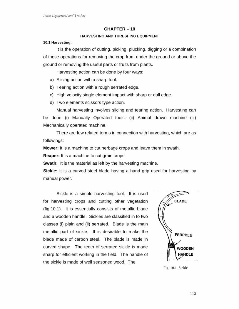
Farm Equipment and Tractors
113
CHAPTER – 10 HARVESTING AND THRESHING EQUIPMENT
10.1 Harvesting:
It is the operation of cutting, picking, plucking, digging or a combination
of these operations for removing the crop from under the ground or above the
ground or removing the useful parts or fruits from plants.
Harvesting action can be done by four ways:
a) Slicing action with a sharp tool.
b) Tearing action with a rough serrated edge.
c) High velocity single element impact with sharp or dull edge.
d) Two elements scissors type action.
Manual harvesting involves slicing and tearing action. Harvesting can
be done (i) Manually Operated tools: (ii) Animal drawn machine (iii)
Mechanically operated machine.
There are few related terms in connection with harvesting, which are as
followings:
Mower: It is a machine to cut herbage crops and leave them in swath.
Reaper: It is a machine to cut grain crops.
Swath: It is the material as left by the harvesting machine.
Sickle: It is a curved steel blade having a hand grip used for harvesting by
manual power.
Sickle is a simple harvesting tool. It is used
for harvesting crops and cutting other vegetation
(fig.10.1). It is essentially consists of metallic blade
and a wooden handle. Sickles are classified in to two
classes (i) plain and (ii) serrated. Blade is the main
metallic part of sickle. It is desirable to make the
blade made of carbon steel. The blade is made in
curved shape. The teeth of serrated sickle is made
sharp for efficient working in the field. The handle of
the sickle is made of well seasoned wood. The
Fig. 10.1. Sickle
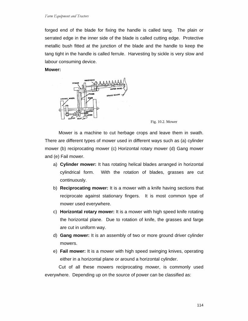
Farm Equipment and Tractors
114
forged end of the blade for fixing the handle is called tang. The plain or
serrated edge in the inner side of the blade is called cutting edge. Protective
metallic bush fitted at the junction of the blade and the handle to keep the
tang tight in the handle is called ferrule. Harvesting by sickle is very slow and
labour consuming device.
Mower:
Mower is a machine to cut herbage crops and leave them in swath.
There are different types of mower used in different ways such as (a) cylinder
mower (b) reciprocating mower (c) Horizontal rotary mower (d) Gang mower
and (e) Fail mower.
a) Cylinder mower: It has rotating helical blades arranged in horizontal
cylindrical form. With the rotation of blades, grasses are cut
continuously.
b) Reciprocating mower: It is a mower with a knife having sections that
reciprocate against stationary fingers. It is most common type of
mower used everywhere.
c) Horizontal rotary mower: It is a mower with high speed knife rotating
the horizontal plane. Due to rotation of knife, the grasses and farge
are cut in uniform way.
d) Gang mower: It is an assembly of two or more ground driver cylinder
mowers.
e) Fail mower: It is a mower with high speed swinging knives, operating
either in a horizontal plane or around a horizontal cylinder.
Cut of all these mowers reciprocating mower, is commonly used
everywhere. Depending up on the source of power can be classified as:
Fig. 10.2. Mower

Farm Equipment and Tractors
115
1.Animal drawn and 2. Tractor drawn. The basic components is of
both these movers are same but main difference lies in power transmitting
unit only.
10.2 Care and maintenance of mower: Apart from regular checking of the oil level in the gear box and
lubrication of the bearing parts of the mower, the following care should be
given for efficient operation of the mower.
1) Loss or damaged knife sections should be either tightened or replaced by
new ones.
2) The pints of the guards should be kept in alignment so that the ledger
plate is at the same level. It can be straightend by a short piece of pipe.
Damaged guards should be replaced.
3) A body worn knife clip or wearing plate should be replaced. Wherever
essential. If the knife clip is high, it can be bent down by hitting it with a
hammer. However, it must not rub against the knife.
4) Each mower is provided with some kind of safety slip clutch to over come
obstructions that a cutter bar may happen to come across. Before using
the mower one should check whether this is working.
5) The knife should be sharpened after it has become dull due to constant
use. A portable hand grinder with a conical grinding stone is generally
used.
6) During the idle season the mower should be placed in a shed with its
cutter bar lifted up.
7) All parts should be kept in correct alignment and lubricated frequently to
assure trouble free service. If the mower is to be operated in sandy oils,
knife guards, wearing plates, knife plated and knife clips should not be
lubricated at all. In other soils, they may be lubricated frequently.
8) The pitman arm, knife section and guards of the mower are always liable
to get damaged. It is good practice to keep these item in stock for quick
replacement.
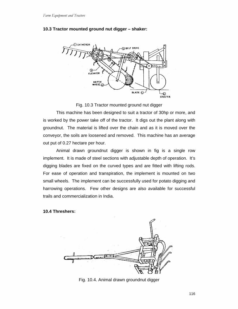
Farm Equipment and Tractors
116
10.3 Tractor mounted ground nut digger – shaker:
Fig. 10.3 Tractor mounted ground nut digger
This machine has been designed to suit a tractor of 30hp or more, and
is worked by the power take off of the tractor. It digs out the plant along with
groundnut. The material is lifted over the chain and as it is moved over the
conveyor, the soils are loosened and removed. This machine has an average
out put of 0.27 hectare per hour.
Animal drawn groundnut digger is shown in fig is a single row
implement. It is made of steel sections with adjustable depth of operation. It’s
digging blades are fixed on the curved types and are fitted with lifting rods.
For ease of operation and transpiration, the implement is mounted on two
small wheels. The implement can be successfully used for potato digging and
harrowing operations. Few other designs are also available for successful
trails and commercialization in India.
10.4 Threshers:
Fig. 10.4. Animal drawn groundnut digger

Farm Equipment and Tractors
117
Threshing: It is the process of detaching grains from the plants.
10.4.1. Principle of threshing: 1) Some impact is given on crops, the grains are separated from panicle,
cobs or pods.
2) The crop mass passes through a gap between drum and concave
wearing or rubbing action takes place. This separates grains from
panicles.
Thus the rupture of the bond between the gains and ears is due to the
factors, like (i) Impacts of spikes over grains (ii) wearing or rubbing action.
The strength of the bond between the grain and the panicle depend
upon: (a) Types of Crops (b) Variety of crops (c) ripening phase of grains and
(d) Moisture content of grain.
The efficiency and quality of threshing depends upon (i) Drum speed
(ii) Number of beaters (iii) Drum size (iv) Gap between drum and concave (v)
Quality and condition of plant mass fed to the thrushed: (vi) Direction of
feeding and (vii) Rate of feeding.
10.5 Threshing methods: The common methods of threshing are :
(a) By manual labour
(b) By animals: and
(c) By machine
(a)Threshing by manual labour: Threshing by manual labour is a slow and labour consuming device.
Process of beating the harvests on a floor or beating by stick is the method
followed for small quantity of harvests.
(b) Threshing by animals: threshing by animals is very common method used in villages. The
harvest is spread on a clean threshing space, the animals are tied in line one
after the other with the help of a strong pole, fixed in the center of the
threshing space. Animals move round and round on the harvest and trample
them continuously till the grains are completely separated from straw. One
man drives the animals from the back.

Farm Equipment and Tractors
118
(c) Threshing by machines: With the increase of mechanisation in farms, threshing machines are
getting popular day by day. Different types of threshers are used for
threshing.
CHAPTER – 10 Short Answer Questions: 1) What are the main parts of sickle?
2) What are the main parts of mower?
3) What is the function of mower?
4) What are the different types of mowers?
5) What is meant by threshing?
Essay type Questions: 1) Explain about harvesting and in how many ways harvesting action can be
done?
2) Explain briefly about sickle with the help of neat sketch?
3) Write about the care and maintenance of mowers?

Farm Equipment and Tractors
119
CHAPTER – 11 PLANT PROTECTION EQUIPMENT
11.0 Plant protection Equipment: With advancement of agricultured science, more fields remains
covered under crops far longer duration of time due to multiple cropping, and
better irrigation facilities. Consequently there is increase in plant pests and
diseases to a considerable extent. So it has become necessary now to use
pesticides and fungicides for controlling the pests and diseases. The
chemicals are applied on plants in the form of spray and dust. Many types of
sprayers and dusters are available in different sizes for plant protection work.
11.1 Principle of pest control: The fundamental strategies of pest control include prevention,
suppression and eradication. A pest could be an insects, diseases or weeds.
Insects feed on leaves, turned or bore in stems, feed on seeds and fruits,
suck and sap from plants and carry plants disease agents. The disease
cause retardation of plant growth, devitalization of plants and deterioration
quality. The weeds reduce crops yield, increase cost of production,
deteriorate crops quality and spoil the beauty of turf and landscape plants.
The control of a pest can be achieved either by natural control force or
using cultural, mechanical, physical, biological, genetic regulatory and
chemical control practices.
11.2 Sprayers: Sprayer is a machine to apply fluid in the form of droplets sprayer is
used for the following purposes :
1. Application of insecticides to control insects pests.
2. Application of fungicides to minimize fungus diseases.
3. Application of insecticides to control insect pests.
4. Application of micro nutrients on the plants.
The main functions of sprayer: (i). To break the liquid into droplets of effective size.
(ii).To distribute them uniformly over the plants.
(iii).To regulate the amount of liquid to avoid excessive application.

Farm Equipment and Tractors
120
Desirable quality of sprayer: I. The sprayer should produce a steady steam of spray materials in the
desired fineness of the practice, so that the plants to be treated may
by covered uniformly.
II. It should deliver the liquid at sufficient pressure so that it reaches all
the foliage and spreads entirely over the sprayed surface.
III. It should be light yet sufficiently strong. Easily workable and
repairable.
11.3 Different Types of Sprayers: 11.3.1 Hand sprayer
It is a light compact and a small unit used for small sprayings jobs in
laboratories, kitchen and gardens. These sprayers are provided with single
action or continuous action air compression pump. When the air is
compressed, it is passed over end of a suction tube which extends down in to
the spray material. When they compressed air escapes through the nozzile it
carries the spray material along with it. The blast of air breaks the spray
material in the form of mist.
11.3.2 Slide pumps Sprayer or Telescopic Lances Sprayer:
Fig.11.1 Hand sprayer
Fig. 11.2 Slide pump sprayer

Farm Equipment and Tractors
121
It has a telescopic pump which is operated with both hands. A spray
nozzle is mounted at the outlet end of pump. The pump barel is held with one
hand and the plunger is operated with the other. The suction lose is placed a
bucket or bottle. It is necessary to continuously pump the sprayer for
uninterrupted spray. It develops low pressure and used in kitchen gardens. It
is cheap and simple and is shown in fig.
(Stripping)
11.3.3 Stirrup Pump Sprayers: (a) Single Barrel stirrup pump:
Fig. 11.3
(b) Double Barrel stirrup pump
Fig. 11.4
A stirrup pump sprayer may be of single barrel or double barrel type.
The sparer has a pump a foot rest a lance and a nozzle.
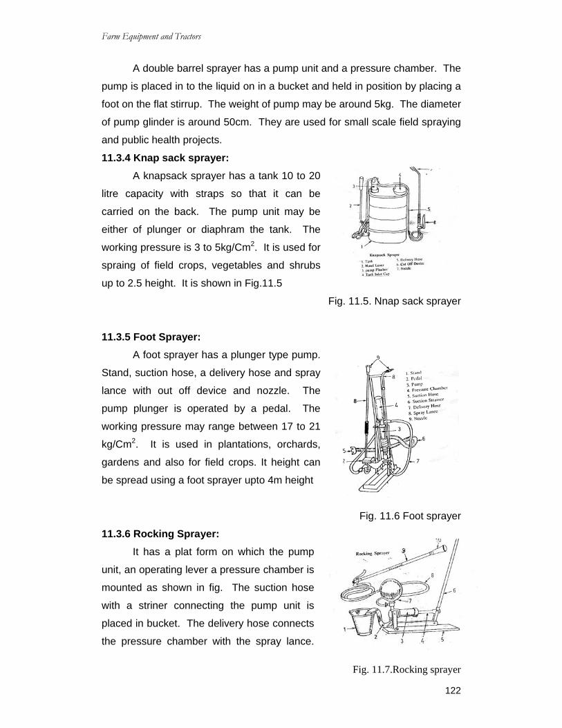
Farm Equipment and Tractors
122
A double barrel sprayer has a pump unit and a pressure chamber. The
pump is placed in to the liquid on in a bucket and held in position by placing a
foot on the flat stirrup. The weight of pump may be around 5kg. The diameter
of pump glinder is around 50cm. They are used for small scale field spraying
and public health projects.
11.3.4 Knap sack sprayer: A knapsack sprayer has a tank 10 to 20
litre capacity with straps so that it can be
carried on the back. The pump unit may be
either of plunger or diaphram the tank. The
working pressure is 3 to 5kg/Cm2. It is used for
spraing of field crops, vegetables and shrubs
up to 2.5 height. It is shown in Fig.11.5
Fig. 11.5. Nnap sack sprayer
11.3.5 Foot Sprayer: A foot sprayer has a plunger type pump.
Stand, suction hose, a delivery hose and spray
lance with out off device and nozzle. The
pump plunger is operated by a pedal. The
working pressure may range between 17 to 21
kg/Cm2. It is used in plantations, orchards,
gardens and also for field crops. It height can
be spread using a foot sprayer upto 4m height
Fig. 11.6 Foot sprayer
11.3.6 Rocking Sprayer: It has a plat form on which the pump
unit, an operating lever a pressure chamber is
mounted as shown in fig. The suction hose
with a striner connecting the pump unit is
placed in bucket. The delivery hose connects
the pressure chamber with the spray lance.
Fig. 11.7.Rocking sprayer

Farm Equipment and Tractors
123
The working pressure ranges between 10 to 20 kg/Cm2 and the maximum
pressure can be as high as 36 kg/Cm2. The hand lever is about one meter
long and has a angular movement of 150 forward and 300 backward. It is used
for spraying tall field crops and trees up to 5m high.
11.3.7 Power Operated Sprayer cum Duster: It is motorized
sprayer, which is
convertible in to a duster.
It uses at 1 to 3 horse
power small petrol engine
running at 5000 to 6000
rpm. The air steam is
produced by a blower
delivers a minimum of 6
cubic metre of air per
Fig. 11.8. Power Operated sprayer cum duster
minute at a velocity not less than 60,m/s. The spray liquid is discharged in to
the air stream through an adjustable nozzle or set of nozzle at a discharge
rate of 0.3 to 0.2 lit/min. The unit when used as a duster can discharge a
minimum of 0.5 kg dust powder per minute. The tank capacity is about 10 to
12 liters. A small fuel tank of 0.75 to litre capacity is also provided. The fuel
consumption varies from 0.6 to 1.85 lit/hr. The unit has a provision to deliver
the parts of air generated from blower in to the tank to form an air cushion
over the liquid delivery. The sprayer can discharge pesticides with an
effective swath width of around 4 to 5 m. horizontally and 3 to 4 m vertically.
It is provided with attachments such as restrictors of different bores, diffusers
and deflectors for adjusting the swath according to requirement. This
machine is used for spraying and dusting of fields crops, glass houses, ware
houses, tall trees up to 6m height.

Farm Equipment and Tractors
124
11.4 Manually operated Rotary Duster: The machine weighs
around 5 to 6kgs. It has an
hopper of 5 liters capacity.
Which is filled to three fourth of
its capacity. A handle when
manually operated drives a
blower through a gear
mechanism. The fan of the
blower displaces more than
0.85m3 of air/min when operated at a speed of 35rpm. An agitator placed
inside the hopper is also driven when the handle is operated. The agitator
prevents the cracking of the dust. The feed rate of dust is controlled using a
feed control lever. It is possible to control the feed rate between 0 to 150
gn/mn at 35 rpm. They are suitable for field crops and particularly the duster
carried on belly is used for dusting tall crops like sugarcane. They can be
used for dusting ware houses and godowns also.
11.5 Care of Power Sprayer: Preparation for operation of power sprayer:
a) Pour mobil oil into the crank case up to the desired level.
b) Put grease in all the grease points.
c) Tighten the suction hose, over flow hose and spray hose.
d) Make sure that there is no break or clogging in the strainer at the end
of the suction hose.
e) Check the ‘V’ belts for damage and tightness.
Actual operation of Power Sprayer:
a) Set the pressure regulator to zero and start the prime mover.
b) Make sure that the chemicals come back to the tank through the over
flow hose.
c) Warm up the sprayer with no load for a few minutes.
Fig.11.9. Manually operated Rotary duster

Farm Equipment and Tractors
125
d) Adjust the pressure regulator up to required pressure.
e) Open the stop cocks to spray the chemicals.
Care after use of Power Sprayer:
a) After spraying, dip the suction hose in to fresh water and run the
sprayer for a few minutes to clean it. Then lift out the suction hose and
run the machine for another few minutes to exhaust the water.
b) Before stopping the prime mover, turn pressure regulator to make the
pressure zero.
c) After spraying, check the machine to see that no screws are loose.
11.5.1 Care and Maintenance of Sprayer: Proper care and maintenance of sprayer prolongs the life of the
machine and gives efficient service. The following are a few important cares
to be observed:
i. All washers and packings should be soaked in oil or water before use.
ii. The end of the nozzle should be unscrewed and cleaned before starting
the work.
iii. When spraying is over the sprayer should be operated for some time with
clean water to remove sediments from the pressure vessel and the
discharge tube. To keep the sprayer serviceable they should be
thoroughly cleaned.
iv. In case of power sprayer, special attention has to be paid to the
followings:
a) Lubricating oil of the engine should be changed every 100
working hours unless other wise advised by the manufacturers.
b) Do not disturb the packing unit if a leak is observed.
c) The spray pump should be worked at more than recommended
pressure.
d) Oil level in the jump of the engine should be checked and all
grease points should be greased once in a day.
e) Recommended oils and fuels should always be used in the
engine.

Farm Equipment and Tractors
126
f) Nozzle should be thoroughly cleaned after use, either by
blowing through it or by using fine bristle. Never try to use thick
wires to clean the perforations.
11.6 Care and Maintenance of Dusters:
a) Duster should be thoroughly cleaned before and after use with a
suitable brush.
b) The hopper should be filled with dust about half of its capacity.
c) The lid of the hopper should be closed during the operation.
d) In rotary dusters, the handle should be cranked at 30 to 35 revolution
per minute for efficient performance.
e) Before storing the duster after use, the dust from the fan box. Suction
piper and hopper should be thoroughly blown out and the agitation
shaft should be properly oiled while kranking.
f) Pieces of paper, sacking and other foreign materials should be
prevented from getting in to the hopper.
g) The agitator parts and dust feed should be occasionally checked for
blockage by foreign matters.
11.7 General precautions for the safe uses of Insecticides: i. The name on the container should be read carefully and manufacturer’s
instruction should be followed.
ii. The pesticides should be kept always in container with proper name.
iii. The pesticides should be stored in a safe and locked place so that
children may not touch them.
iv. The pesticides should never be placed near food stuff or medicines.
v. Empty containers of dangerous pesticides should not be used for any
alternative purpose.
vi. Necessary protective clothing should be used while handling pesticides.
The pesticides bags should not be torn but they should be cut with a knife.

Farm Equipment and Tractors
127
CHAPTER – 11
Short answer questions 1. What are the different types of plant protection equipments?
2. What is the function of sprayer?
3. What are the main parts of hand sprayer?
4. What are the main parts of knapsack sprayer?
5. What are the main parts of foot sprayer?
6. What are the main parts of power operated sprayer?
Essay Questions: 1. Explain briefly about any one of the sprayers?
2. What type of cares has to be taken after using the power sprayer?
3. Write a note on general care and maintenance of sprayer?
4. What are the general precautions to be taken for the safe use of
insecticides?