Embed Size (px)
Citation preview
1
Manual for use and maintenance
Farm Silo Load Cell Silo Weighing Scale
Ag/MIS/UmGB-2200-06/14 rev 1.3 P/N: 110306
Farm Silo Load Cell
© Munters AB, 2014 2
Farm Silo Load Cell Manual for use and maintenance Revision: N.1.3 of 06.2014 Product Software: N/A This manual for use and maintenance is an integral part of the apparatus together with the attached technical documentation.
This document is destined for the user of the apparatus: it may not be reproduced in whole or in part, committed to computer memory as a file or delivered to third parties without the prior authorization of the assembler of the system. Munters reserves the right to effect modifications to the apparatus in accordance with technical and legal developments.
© Munters AB, 2014 3
Index
Chapter page
1 INTRODUCTION ---------------------------------------------------------------------------------------- 4
1.1 Disclaimer ----------------------------------------------------------------------------------------------------------- 4 1.2 Introduction --------------------------------------------------------------------------------------------------------- 4 1.3 Notes ---------------------------------------------------------------------------------------------------------------- 4
2 INSTALLATION ------------------------------------------------------------------------------------------ 5
2.1 Installing the Load Cell ------------------------------------------------------------------------------------------ 5 2.2 Wiring the Load Cells ------------------------------------------------------------------------------------------- 7 2.3 Load Cell Test Procedure ------------------------------------------------------------------------------------- 12
3 TROUBLESHOOTING -------------------------------------------------------------------------------- 13
4 WARRANTY -------------------------------------------------------------------------------------------- 18
© Munters AB, 2014 4
1 Introduction
1.1 Disclaimer
Munters reserves the right to make alterations to specifications, quantities, dimensions etc. for production or other reasons, subsequent to publication. The information contained herein has been prepared by qualified experts within Munters. While we believe the information is accurate and complete, we make no warranty or representation for any particular purposes. The information is offered in good faith and with the understanding that any use of the units or accessories in breach of the directions and warnings in this document is at the sole discretion and risk of the user.
1.2 Introduction
Congratulations on your excellent choice of purchasing an Farm Silo! In order to realize the full benefit from this product it is important that it is installed, commissioned and operated correctly. Before installation or using the fan, this manual should be studied carefully. It is also recommended that it is kept safely for future reference. The manual is intended as a reference for installation, commissioning and day-to-day operation of the Munters Controllers.
1.3 Notes
Date of release: July 2010 Munters cannot guarantee to inform users about the changes or to distribute new manuals to them.
NOTE All rights reserved. No part of this manual may be reproduced in any manner whatsoever without the expressed written permission of Munters. The contents of this manual are subject to change without notice.
© Munters AB, 2014 5
2 Installation
The following sections detail how to install the:
• Farm Silo -4: Four tons • Farm Silo -10: 10 tons
2.1 Installing the Load Cell
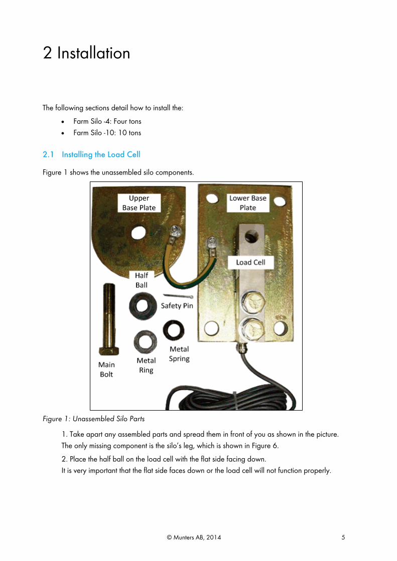
Figure 1 shows the unassembled silo components.
Figure 1: Unassembled Silo Parts
1. Take apart any assembled parts and spread them in front of you as shown in the picture. The only missing component is the silo’s leg, which is shown in Figure 6.
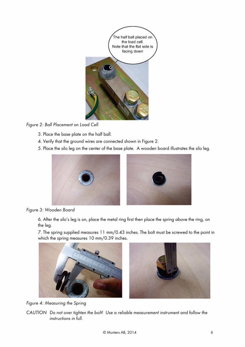
2. Place the half ball on the load cell with the flat side facing down. It is very important that the flat side faces down or the load cell will not function properly.
© Munters AB, 2014 6
Figure 2: Ball Placement on Load Cell
3. Place the base plate on the half ball. 4. Verify that the ground wires are connected shown in Figure 2. 5. Place the silo leg on the center of the base plate. A wooden board illustrates the silo leg.
Figure 3: Wooden Board
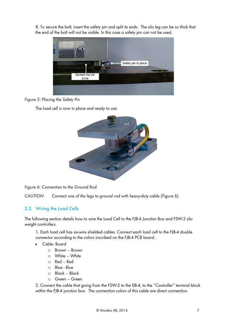
6. After the silo’s leg is on, place the metal ring first then place the spring above the ring, on the leg. 7. The spring supplied measures 11 mm/0.43 inches. The bolt must be screwed to the point in which the spring measures 10 mm/0.39 inches.
Figure 4: Measuring the Spring
CAUTION Do not over tighten the bolt! Use a reliable measurement instrument and follow the instructions in full.
© Munters AB, 2014 7
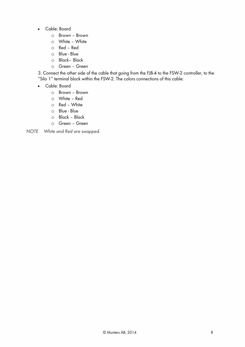
8. To secure the bolt, insert the safety pin and split its ends. The silo leg can be so thick that the end of the bolt will not be visible. In this case a safety pin can not be used.
Figure 5: Placing the Safety Pin
The load cell is now in place and ready to use.
Figure 6: Connection to the Ground Rod
CAUTION Connect one of the legs to ground rod with heavy-duty cable (Figure 6).
2.2 Wiring the Load Cells
The following section details how to wire the Load Cell to the FJB-4 Junction Box and FSW-2 silo weight controllers.
1. Each load cell has six-wire shielded cables. Connect each load cell to the FJB-4 double connector according to the colors inscribed on the FJB-4 PCB board .
• Cable: Board o Brown – Brown o White – White o Red – Red o Blue - Blue o Black – Black o Green – Green
2. Connect the cable that going from the FSW-2 to the fJB-4, to the “Controller” terminal block within the FJB-4 junction box. The connection colors of this cable are direct connection.
© Munters AB, 2014 8
• Cable: Board o Brown – Brown o White – White o Red – Red o Blue - Blue o Black– Black o Green – Green
3. Connect the other side of the cable that going from the FJB-4 to the FSW-2 controller, to the “Silo 1” terminal block within the FSW-2. The colors connections of this cable: • Cable: Board
o Brown – Brown o White – Red o Red – White o Blue - Blue o Black – Black o Green – Green
NOTE White and Red are swapped.
© Munters AB, 2014 9
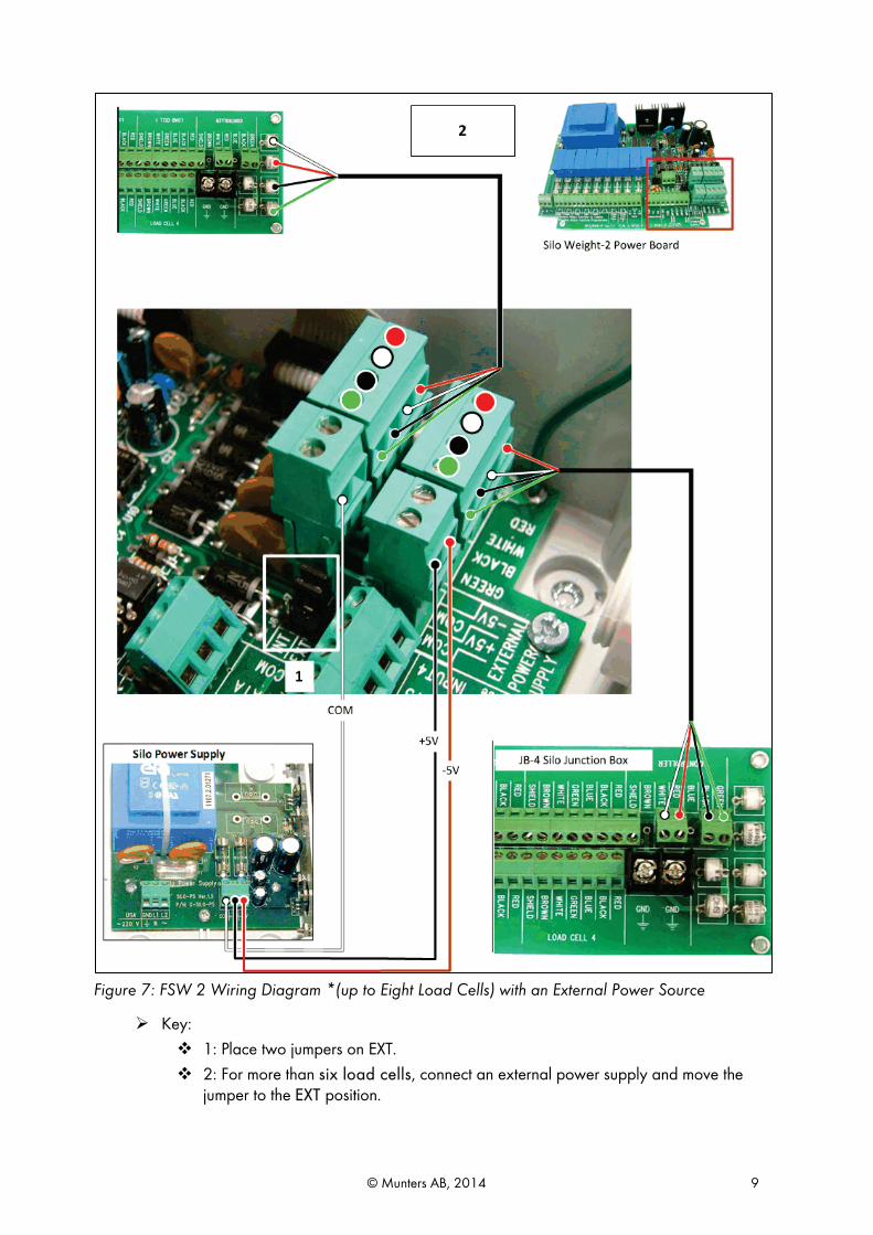
Figure 7: FSW 2 Wiring Diagram *(up to Eight Load Cells) with an External Power Source
Key: 1: Place two jumpers on EXT. 2: For more than six load cells, connect an external power supply and move the
jumper to the EXT position.
© Munters AB, 2014 10
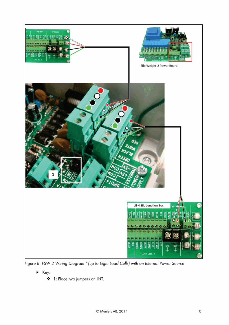
Figure 8: FSW 2 Wiring Diagram *(up to Eight Load Cells) with an Internal Power Source
Key: 1: Place two jumpers on INT.
© Munters AB, 2014 11
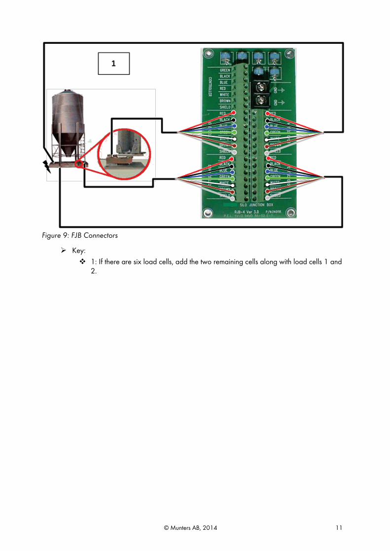
Figure 9: FJB Connectors
Key: 1: If there are six load cells, add the two remaining cells along with load cells 1 and
2.
© Munters AB, 2014 12
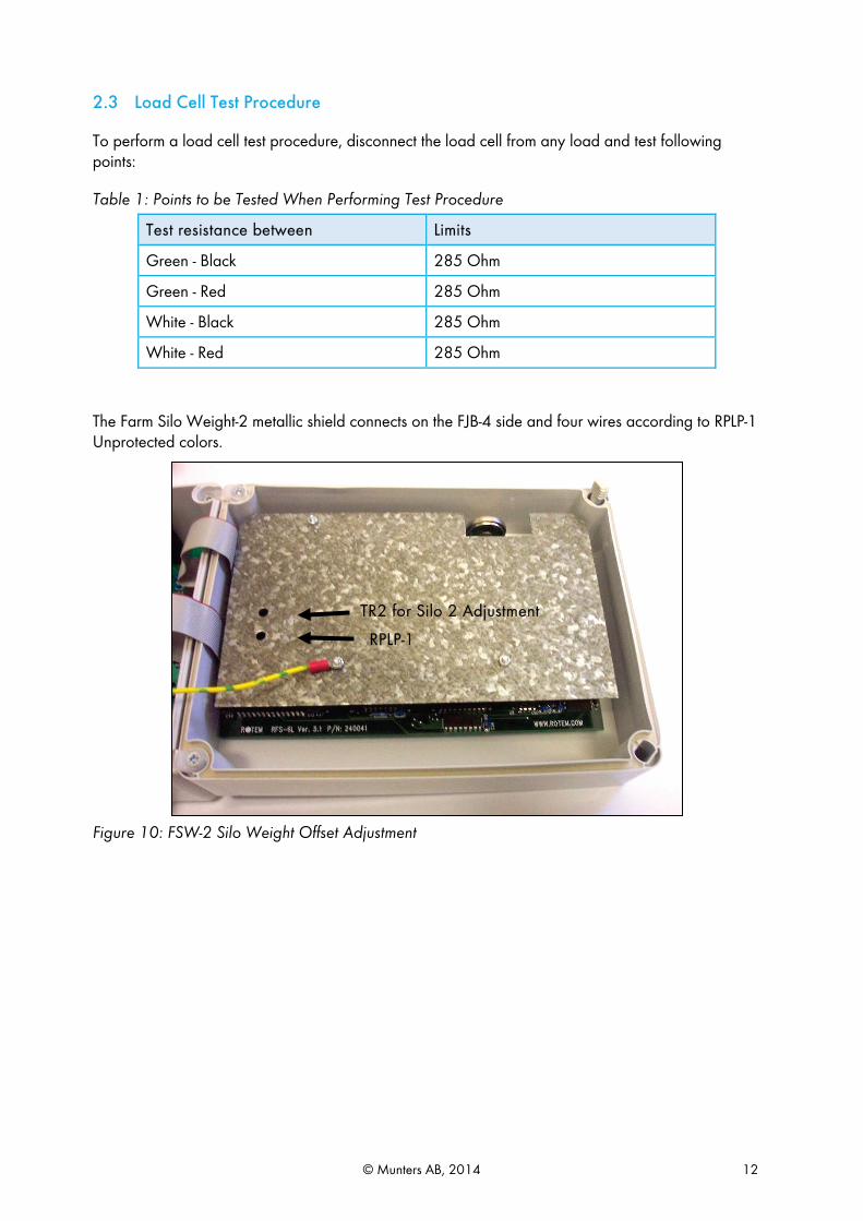
2.3 Load Cell Test Procedure
To perform a load cell test procedure, disconnect the load cell from any load and test following points:
Table 1: Points to be Tested When Performing Test Procedure
Test resistance between Limits
Green - Black 285 Ohm
Green - Red 285 Ohm
White - Black 285 Ohm
White - Red 285 Ohm
The Farm Silo Weight-2 metallic shield connects on the FJB-4 side and four wires according to RPLP-1 Unprotected colors.
Figure 10: FSW-2 Silo Weight Offset Adjustment
RPLP-1
TR2 for Silo 2 Adjustment
© Munters AB, 2014 13
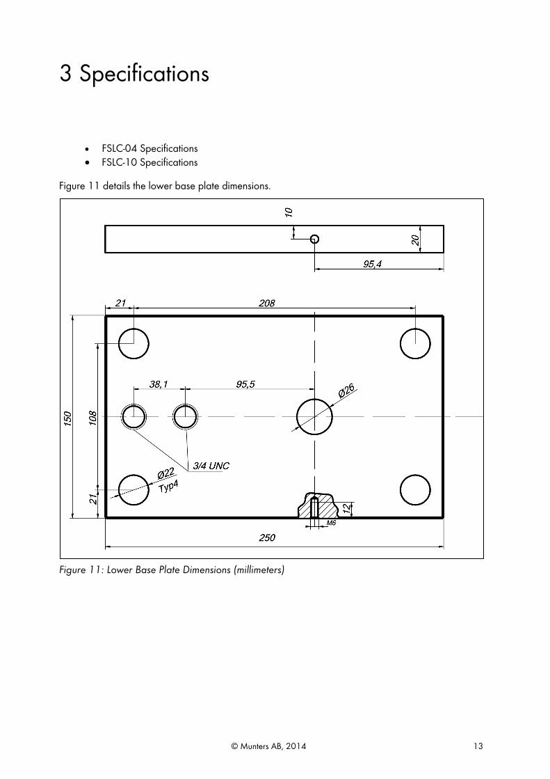
3 Specifications
• FSLC-04 Specifications • FSLC-10 Specifications
Figure 11 details the lower base plate dimensions.
Figure 11: Lower Base Plate Dimensions (millimeters)
© Munters AB, 2014 14
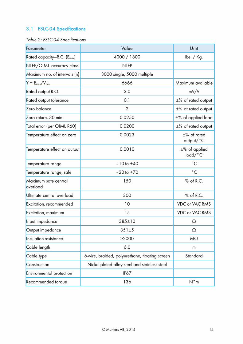
3.1 FSLC-04 Specifications
Table 2: FSLC-04 Specifications
Parameter Value Unit
Rated capacity—R.C. (Emax) 4000 / 1800 lbs. / Kg.
NTEP/OIML accuracy class NTEP
Maximum no. of intervals (n) 3000 single, 5000 multiple
Y = Emax/Vmin 6666 Maximum available
Rated output-R.O. 3.0 mV/V
Rated output tolerance 0.1 ±% of rated output
Zero balance 2 ±% of rated output
Zero return, 30 min. 0.0250 ±% of applied load
Total error (per OIML R60) 0.0200 ±% of rated output
Temperature effect on zero 0.0023 ±% of rated output/°C
Temperature effect on output 0.0010 ±% of applied load/°C
Temperature range –10 to +40 °C
Temperature range, safe –20 to +70 °C
Maximum safe central overload
150 % of R.C.
Ultimate central overload 300 % of R.C.
Excitation, recommended 10 VDC or VAC RMS
Excitation, maximum 15 VDC or VAC RMS
Input impedance 385±10 Ω
Output impedance 351±5 Ω
Insulation resistance >2000 MΩ
Cable length 6.0 m
Cable type 6-wire, braided, polyurethane, floating screen Standard
Construction Nickel-plated alloy steel and stainless steel
Environmental protection IP67
Recommended torque 136 N*m
© Munters AB, 2014 15
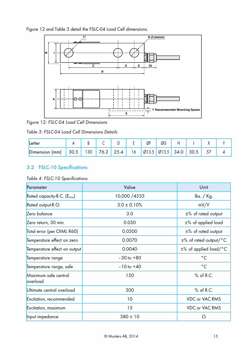
Figure 12 and Table 3 detail the FSLC-04 Load Cell dimensions.
Figure 12: FSLC-04 Load Cell Dimensions
Table 3: FSLC-04 Load Cell Dimensions Details
Letter A B C D E ØF ØG H I X Y
Dimension (mm) 30.5 130 76.2 25.4 16 Ø13.5 Ø13.5 34.0 30.5 57 4
3.2 FSLC-10 Specifications
Table 4: FSLC-10 Specifications
Parameter Value Unit
Rated capacity-R.C. (Emax) 10,000 /4535 lbs. / Kg.
Rated output-R.O. 3.0 ± 0.10% mV/V
Zero balance 3.0 ±% of rated output
Zero return, 30 min. 0.050 ±% of applied load
Total error (per OIML R60) 0.0500 ±% of rated output
Temperature effect on zero 0.0070 ±% of rated output/°C
Temperature effect on output 0.0040 ±% of applied load/°C
Temperature range –30 to +80 °C
Temperature range, safe –10 to +40 °C
Maximum safe central overload
150 % of R.C.
Ultimate central overload 300 % of R.C.
Excitation, recommended 10 VDC or VAC RMS
Excitation, maximum 15 VDC or VAC RMS
Input impedance 380 ± 10 Ω
© Munters AB, 2014 16
Parameter Value Unit
Output impedance 350 ± 3 Ω
Deflection at rated capacity < 0.4 mm
Insulation resistance >2000 MΩ
Cable length 6.0 m
Cable type 6-wire, braided, polyurethane, dual floating screen
Standard
Construction Electrolysis, nickel-plated steel
Environmental protection IP67
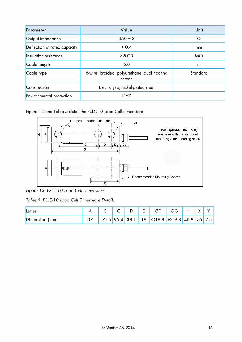
Figure 13 and Table 5 detail the FSLC-10 Load Cell dimensions.
Figure 13: FSLC-10 Load Cell Dimensions
Table 5: FSLC-10 Load Cell Dimensions Details
Letter A B C D E ØF ØG H X Y
Dimension (mm) 37 171.5 95.4 38.1 19 Ø19.8 Ø19.8 40.9 76 7.5

© Munters AB, 2014 17
4 Troubleshooting
# Problem Description Troubleshooting
1 Installation and filling feed has been done but silo stops weighing.
If the display of Silo A does not show A/D '65536' counts on 16 bits, lower the offset (see Figure 7) until this number changes. After receiving numbers shown on the screen, reducing the numbers should be done according to: [65536 – (number of Kg missing in the silo * Silo 1 Scale Factor)] After new installation is done and the Silo is empty, the A/D reading should be around 1000 counts (near zero), use the offset feature to get it. If the display shows '0', increase it by using offset feature.
2
The controller display shows “disconnected” (or Error) and the test menu shows 65,536 or 0 rather than a voltage measurement that is required in order to identify the error.
Check if FJB-4 received voltage from controller (green and black wires from controller should be approximately 10 DCV). If not received, check wire connections on the controller's side. If 10 DCV is received, load cells must be checked (see Table 1 and Figure 9 for further explanation): Take White and Green wires from each load cell and check their voltage using a digital multi meter (the amount is not important but it must be identical throughout load cells with a difference of up to 2 mV). If difference is more than 2mV there is a problem with one of the load cells. The range of voltage should be between 0 to 20 mV depending on Silo load. In some cases, when the prior test is not effective and voltage between Black (common) wire and White, and between Black and Green, wires must be checked (amount of voltage must be between 4-4.5V and identical throughout load cells).
© Munters AB, 2014 18
5 Warranty
Warranty and technical assistance
Munters products are designed and built to provide reliable and satisfactory performance but cannot be guaranteed free of faults; although they are reliable products they can develop unforeseeable defects and the user must take this into account and arrange adequate emergency or alarm systems if failure to operate could cause damage to the articles for which the Munters plant was required: if this is not done, the user is fully responsible for the damage which they could suffer.
Munters extends this limited warranty to the first purchaser and guarantees its products to be free from defects originating in manufacture or materials for one year from the date of delivery, provided that suitable transport, storage, installation and maintenance terms are complied with. The warranty does not apply if the products have been repaired without express authorisation from Munters, or repaired in such a way that, in Munters’ judgement, their performance and reliability have been impaired, or incorrectly installed, or subjected to improper use. The user accepts total responsibility for incorrect use of the products.
The warranty on products from outside suppliers fitted to Farm Silo Weighing Controller, (for example cables, scales, power supplies, etc.) is limited to the conditions stated by the supplier: all claims must be made in writing within eight days of the discovery of the defect and within 12 months of the delivery of the defective product. Munters has thirty days from the date of receipt in which to take action, and has the right to examine the product at the customer’s premises or at its own plant (carriage cost to be borne by the customer).
Munters at its sole discretion has the option of replacing or repairing, free of charge, products which it considers defective, and will arrange for their despatch back to the customer carriage paid. In the case of faulty parts of small commercial value which are widely available (such as bolts, etc.) for urgent despatch, where the cost of carriage would exceed the value of the parts, Munters may authorise the customer exclusively to purchase the replacement parts locally; Munters will reimburse the value of the product at its cost price.
Munters will not be liable for costs incurred in demounting the defective part, or the time required to travel to site and the associated travel costs. No agent, employee or dealer is authorised to give any further guarantees or to accept any other liability on Munters’ behalf in connection with other Munters products, except in writing with the signature of one of the Company’s Managers. WARNING: In the interests of improving the quality of its products and services, Munters reserves the right at any time and without prior notice to alter the specifications in this manual. The liability of the manufacturer Munters ceases in the event of:
• dismantling the safety devices; • use of unauthorised materials;
© Munters AB, 2014 19
• inadequate maintenance; • use of non-original spare parts and accessories.
Barring specific contractual terms, the following are directly at the user’s expense:
• preparing installation sites; • providing an electricity supply (including the protective equipotential bonding (PE) conductor, in
accordance with CEI EN 60204-1, paragraph 8.2), for correctly connecting the equipment to the mains electricity supply;
• providing ancillary services appropriate to the requirements of the plant on the basis of the information supplied with regard to installation;
• tools and consumables required for fitting and installation; • lubricants necessary for commissioning and maintenance.
It is mandatory to purchase and use only original spare parts or those recommended by the manufacturer. Dismantling and assembly must be performed by qualified technicians and according to the manufacturer’s instructions.
The use of non-original spare parts or incorrect assembly exonerates the manufacturer from all liability.
Requests for technical assistance and spare parts can be made directly to the nearest Munters office. A full list of contact details can be found on the back page of this manual.

© Munters AB, 2012
www.munters.com Australia Munters Pty Limited, Phone +61 2 6025 6422, Brazil Munters Brasil Industria e Comercio Ltda, Phone +55 41 3317 5050, Canada Munters Corporation Mason, Phone +1 517 676 7070, China Munters Air Treatment Equipment (Beijing) Co. Ltd, Phone +86 10 80 481 121, Denmark Munters A/S, Phone +45 9862 3311, India Munters India, Phone +91 20 3052 2520, Indonesia Munters, Phone +62 818 739 235, Italy Munters Italy S.p.A., Chiusavecchia, Phone +39 0183 52 11, Japan Munters K.K., Phone +81 3 5970 0021, Korea Munters Korea Co. Ltd., Phone +82 2 761 8701, Mexico Munters Mexico, Phone +52 818 262 54 00, Russia Munters AB, Phone +7 812 448 5740, Singapore Munters Pte Ltd., Phone +65 744 6828, South Africa and Sub-Sahara Countries Munters (Pty) Ltd., Phone +27 11 997 2000, Spain Munters Spain S.A., Phone +34 91 640 09 02, Sweden Munters AB, Phone +46 8 626 63 00, Thailand Munters Co. Ltd., Phone +66 2 642 2670, Turkey Munters Form Endüstri Sistemleri A.Ş, Phone +90 322 231 1338, USA Munters Corporation Mason, Phone
+1 517 676 7070, Vietnam Munters Vietnam, Phone +84 8 3825 6838, Export & Other countries Munters Italy S.p.A., Chiusavecchia Phone +39 0183 52 11 Ag/
MIS
/Um
GB-
2200
-06/
14 re
v 1.
3