Embed Size (px)
Citation preview
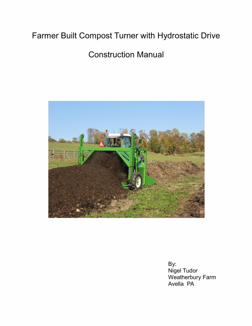
Farmer Built Compost Turner with Hydrostatic Drive
Construction Manual
By: Nigel Tudor Weatherbury Farm Avella PA
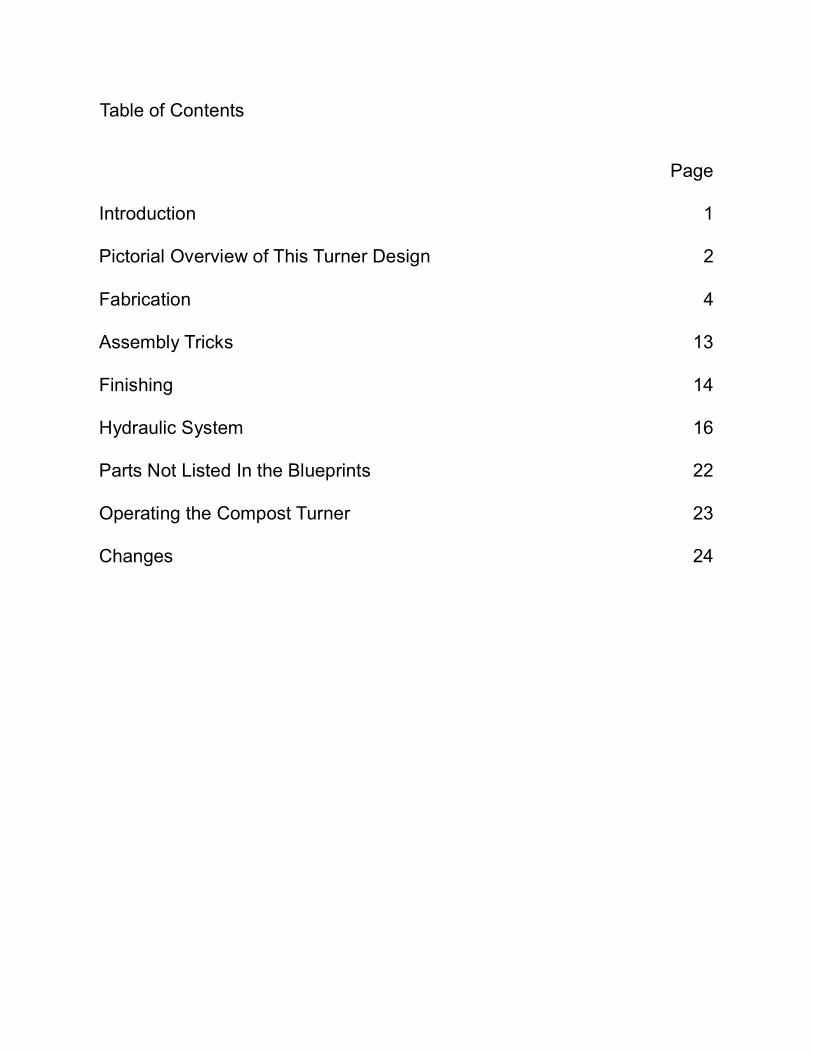
Table of Contents
Introduction Pictorial Overview of This Turner Design Fabrication Assembly Tricks Finishing Hydraulic System Parts Not Listed In the Blueprints Operating the Compost Turner Changes
Page
1
2
4
13
14
16
22
23
24
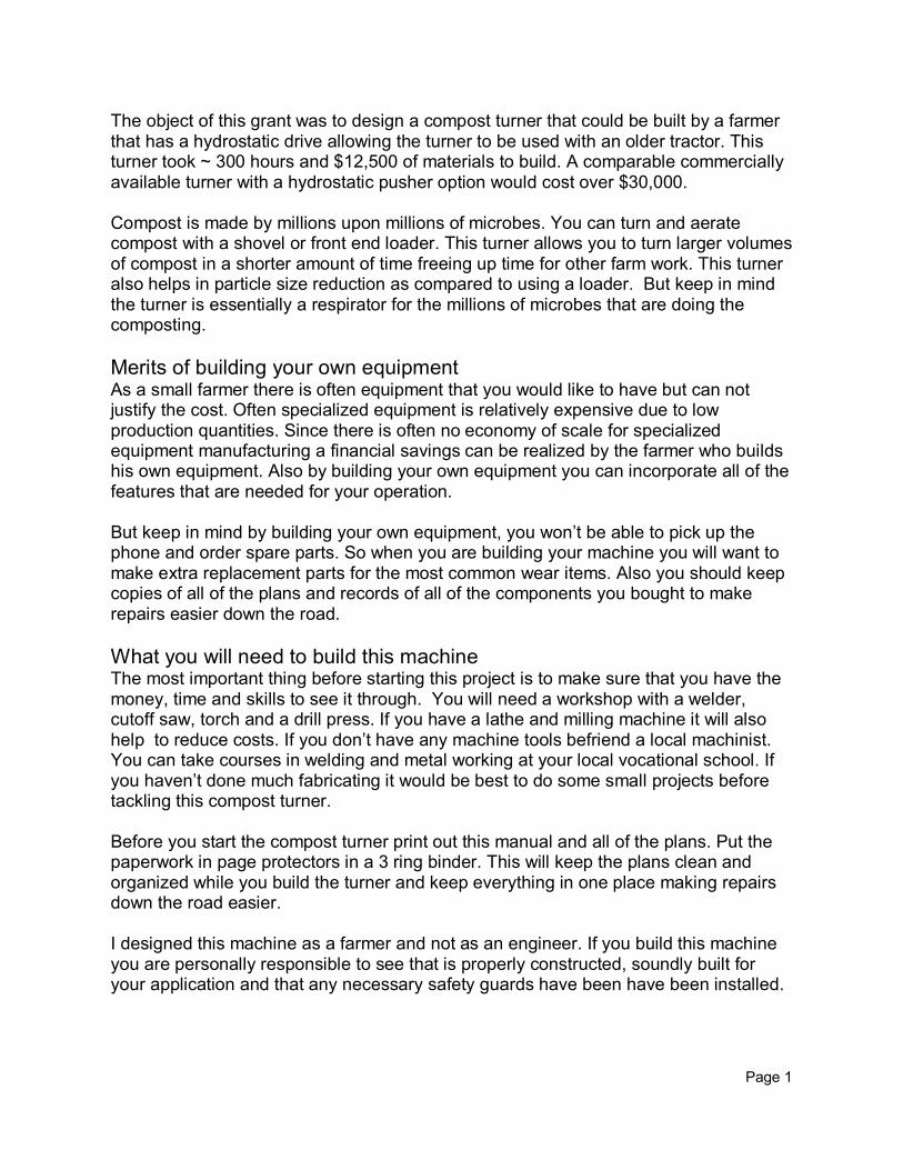
The object of this grant was to design a compost turner that could be built by a farmer that has a hydrostatic drive allowing the turner to be used with an older tractor. This turner took ~ 300 hours and $12,500 of materials to build. A comparable commercially available turner with a hydrostatic pusher option would cost over $30,000. Compost is made by millions upon millions of microbes. You can turn and aerate compost with a shovel or front end loader. This turner allows you to turn larger volumes of compost in a shorter amount of time freeing up time for other farm work. This turner also helps in particle size reduction as compared to using a loader. But keep in mind the turner is essentially a respirator for the millions of microbes that are doing the composting.
Merits of building your own equipment As a small farmer there is often equipment that you would like to have but can not justify the cost. Often specialized equipment is relatively expensive due to low production quantities. Since there is often no economy of scale for specialized equipment manufacturing a financial savings can be realized by the farmer who builds his own equipment. Also by building your own equipment you can incorporate all of the features that are needed for your operation. But keep in mind by building your own equipment, you won’t be able to pick up the phone and order spare parts. So when you are building your machine you will want to make extra replacement parts for the most common wear items. Also you should keep copies of all of the plans and records of all of the components you bought to make repairs easier down the road.
What you will need to build this machine The most important thing before starting this project is to make sure that you have the money, time and skills to see it through. You will need a workshop with a welder, cutoff saw, torch and a drill press. If you have a lathe and milling machine it will also help to reduce costs. If you don’t have any machine tools befriend a local machinist. You can take courses in welding and metal working at your local vocational school. If you haven’t done much fabricating it would be best to do some small projects before tackling this compost turner. Before you start the compost turner print out this manual and all of the plans. Put the paperwork in page protectors in a 3 ring binder. This will keep the plans clean and organized while you build the turner and keep everything in one place making repairs down the road easier. I designed this machine as a farmer and not as an engineer. If you build this machine you are personally responsible to see that is properly constructed, soundly built for your application and that any necessary safety guards have been have been installed.
Page 1
Pictorial Overview of This Turner Design
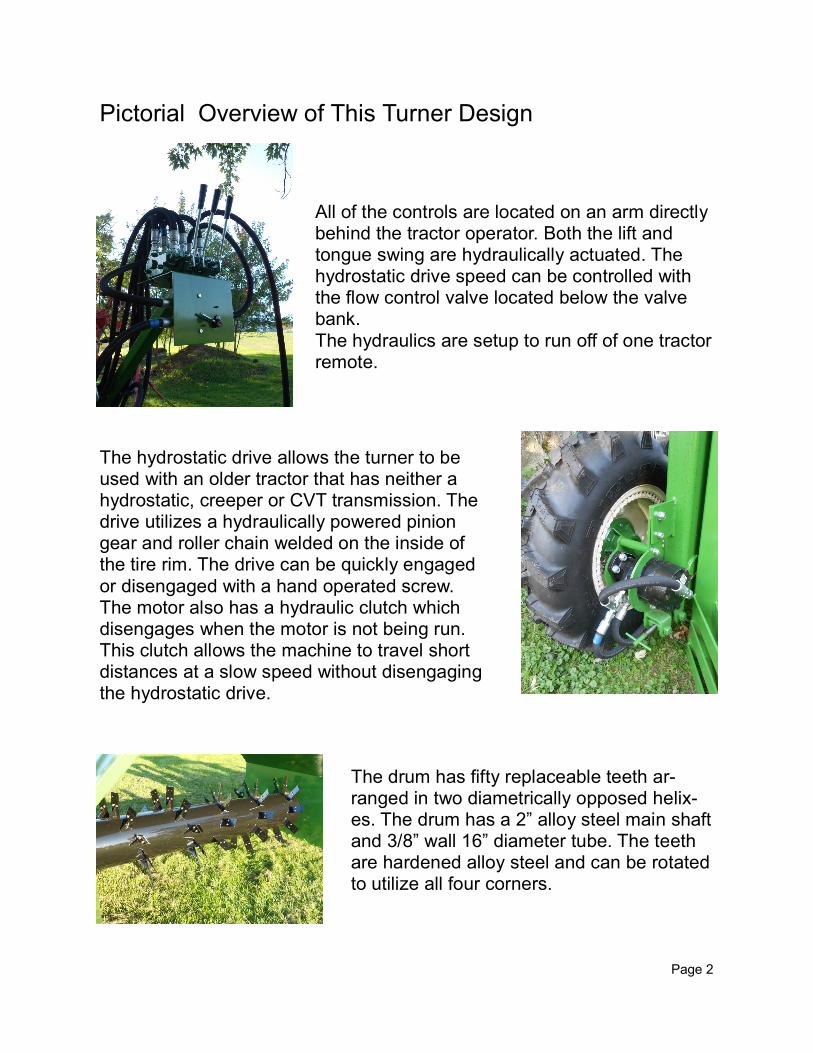
All of the controls are located on an arm directly behind the tractor operator. Both the lift and tongue swing are hydraulically actuated. The hydrostatic drive speed can be controlled with the flow control valve located below the valve bank. The hydraulics are setup to run off of one tractor remote.
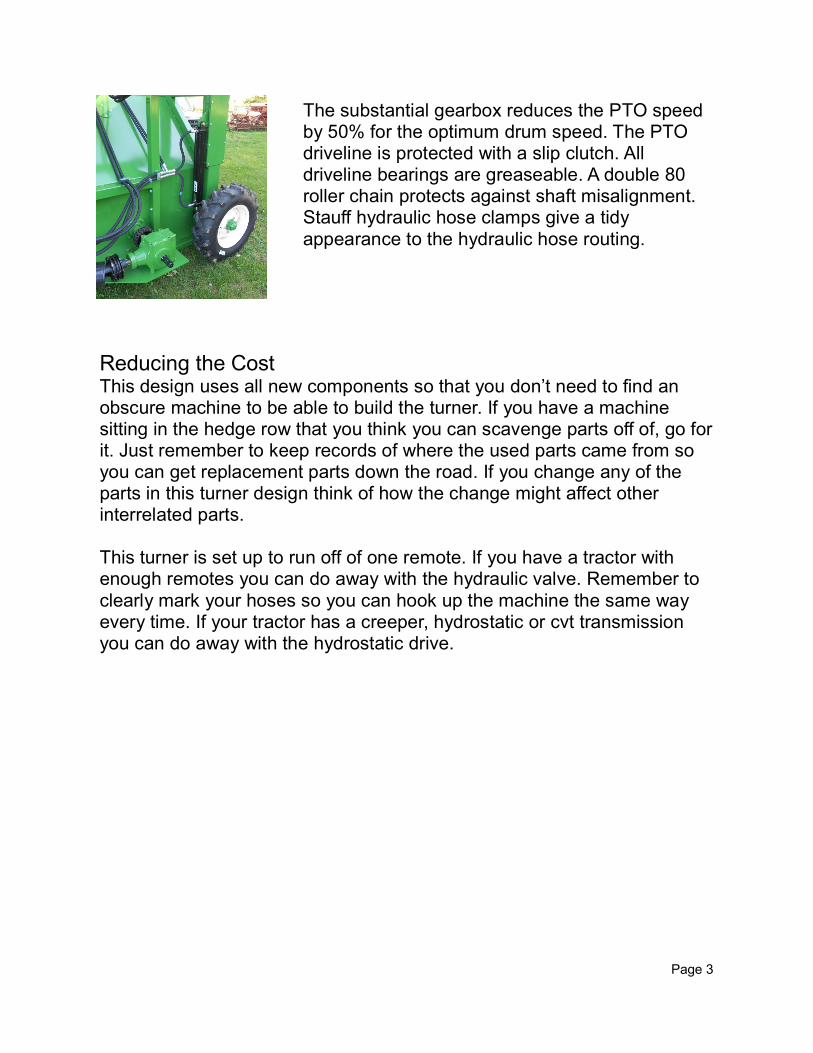
The hydrostatic drive allows the turner to be used with an older tractor that has neither a hydrostatic, creeper or CVT transmission. The drive utilizes a hydraulically powered pinion gear and roller chain welded on the inside of the tire rim. The drive can be quickly engaged or disengaged with a hand operated screw. The motor also has a hydraulic clutch which disengages when the motor is not being run. This clutch allows the machine to travel short distances at a slow speed without disengaging the hydrostatic drive.
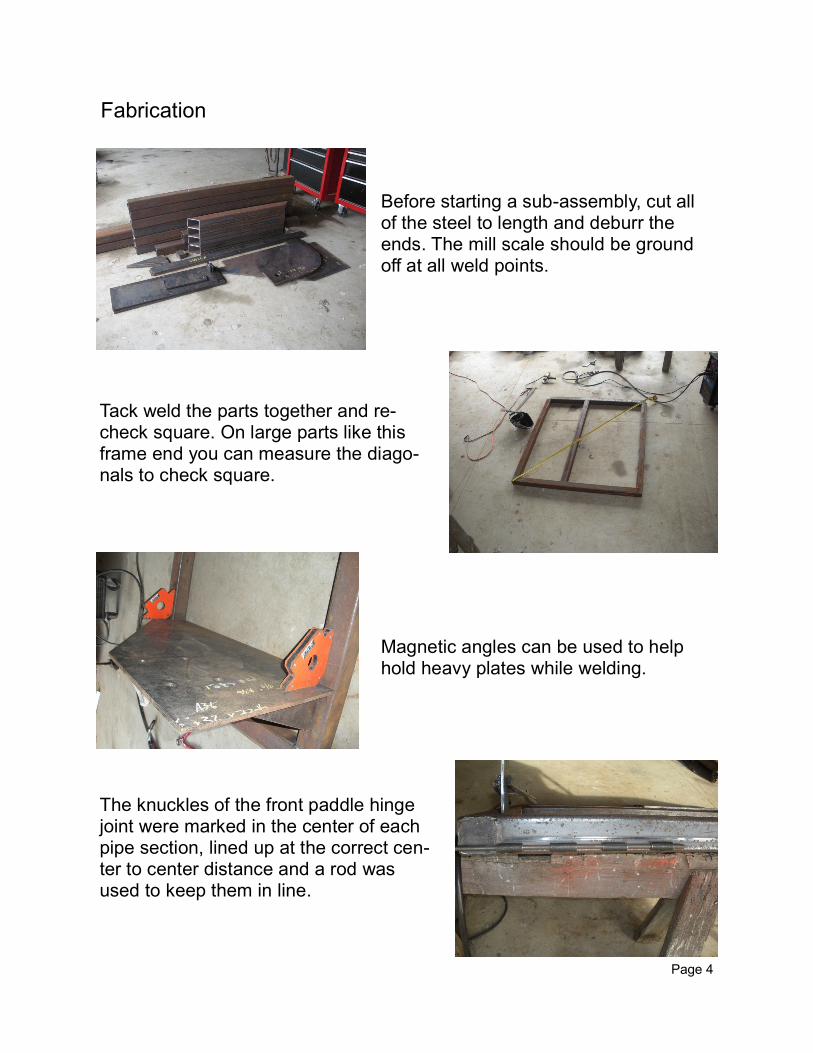
The drum has fifty replaceable teeth ar-ranged in two diametrically opposed helix-es. The drum has a 2” alloy steel main shaft and 3/8” wall 16” diameter tube. The teeth are hardened alloy steel and can be rotated to utilize all four corners.
Page 2
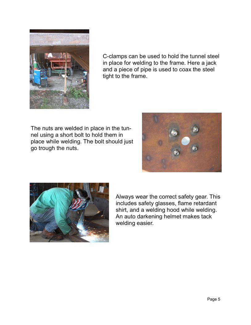
The substantial gearbox reduces the PTO speed by 50% for the optimum drum speed. The PTO driveline is protected with a slip clutch. All driveline bearings are greaseable. A double 80 roller chain protects against shaft misalignment. Stauff hydraulic hose clamps give a tidy appearance to the hydraulic hose routing.
Reducing the Cost This design uses all new components so that you don’t need to find an obscure machine to be able to build the turner. If you have a machine sitting in the hedge row that you think you can scavenge parts off of, go for it. Just remember to keep records of where the used parts came from so you can get replacement parts down the road. If you change any of the parts in this turner design think of how the change might affect other interrelated parts. This turner is set up to run off of one remote. If you have a tractor with enough remotes you can do away with the hydraulic valve. Remember to clearly mark your hoses so you can hook up the machine the same way every time. If your tractor has a creeper, hydrostatic or cvt transmission you can do away with the hydrostatic drive.
Page 3
Before starting a sub-assembly, cut all of the steel to length and deburr the ends. The mill scale should be ground off at all weld points.
Tack weld the parts together and re-check square. On large parts like this frame end you can measure the diago-nals to check square.
Magnetic angles can be used to help hold heavy plates while welding.
The knuckles of the front paddle hinge joint were marked in the center of each pipe section, lined up at the correct cen-ter to center distance and a rod was used to keep them in line.
Page 4
Fabrication
C-clamps can be used to hold the tunnel steel in place for welding to the frame. Here a jack and a piece of pipe is used to coax the steel tight to the frame.
The nuts are welded in place in the tun-nel using a short bolt to hold them in place while welding. The bolt should just go trough the nuts.
Always wear the correct safety gear. This includes safety glasses, flame retardant shirt, and a welding hood while welding. An auto darkening helmet makes tack welding easier.
Page 5
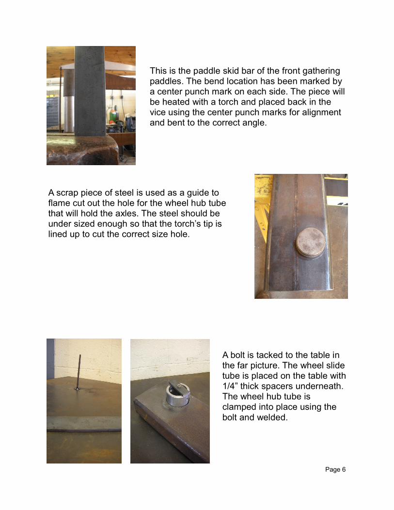
This is the paddle skid bar of the front gathering paddles. The bend location has been marked by a center punch mark on each side. The piece will be heated with a torch and placed back in the vice using the center punch marks for alignment and bent to the correct angle.
A scrap piece of steel is used as a guide to flame cut out the hole for the wheel hub tube that will hold the axles. The steel should be under sized enough so that the torch’s tip is lined up to cut the correct size hole.
A bolt is tacked to the table in the far picture. The wheel slide tube is placed on the table with 1/4” thick spacers underneath. The wheel hub tube is clamped into place using the bolt and welded.
Page 6
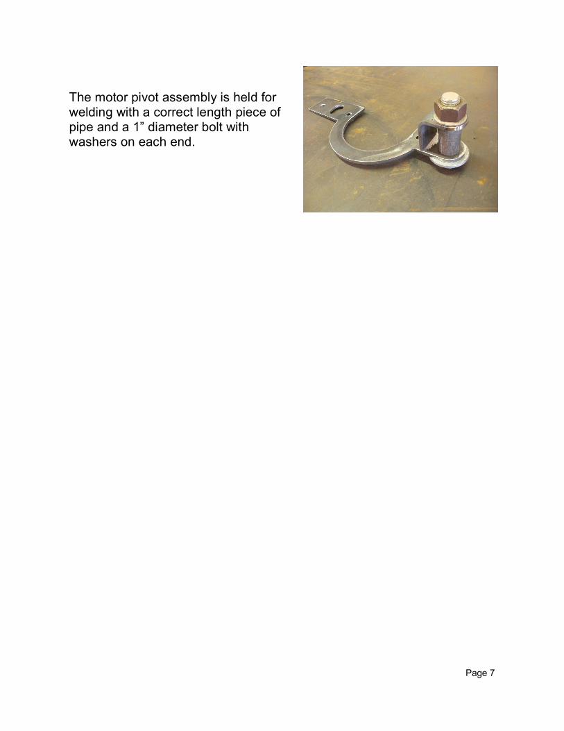
The motor pivot assembly is held for welding with a correct length piece of pipe and a 1” diameter bolt with washers on each end.
Page 7
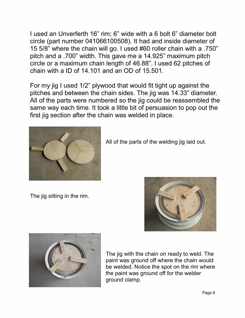
I used an Unverferth 16” rim; 6” wide with a 6 bolt 6” diameter bolt circle (part number 041066100508). It had and inside diameter of 15 5/8” where the chain will go. I used #60 roller chain with a .750” pitch and a .700” width. This gave me a 14.925” maximum pitch circle or a maximum chain length of 46.88”. I used 62 pitches of chain with a ID of 14.101 and an OD of 15.501. For my jig I used 1/2” plywood that would fit tight up against the pitches and between the chain sides. The jig was 14.33” diameter. All of the parts were numbered so the jig could be reassembled the same way each time. It took a little bit of persuasion to pop out the first jig section after the chain was welded in place.
All of the parts of the welding jig laid out.
The jig sitting in the rim.
The jig with the chain on ready to weld. The paint was ground off where the chain would be welded. Notice the spot on the rim where the paint was ground off for the welder ground clamp.
Page 8
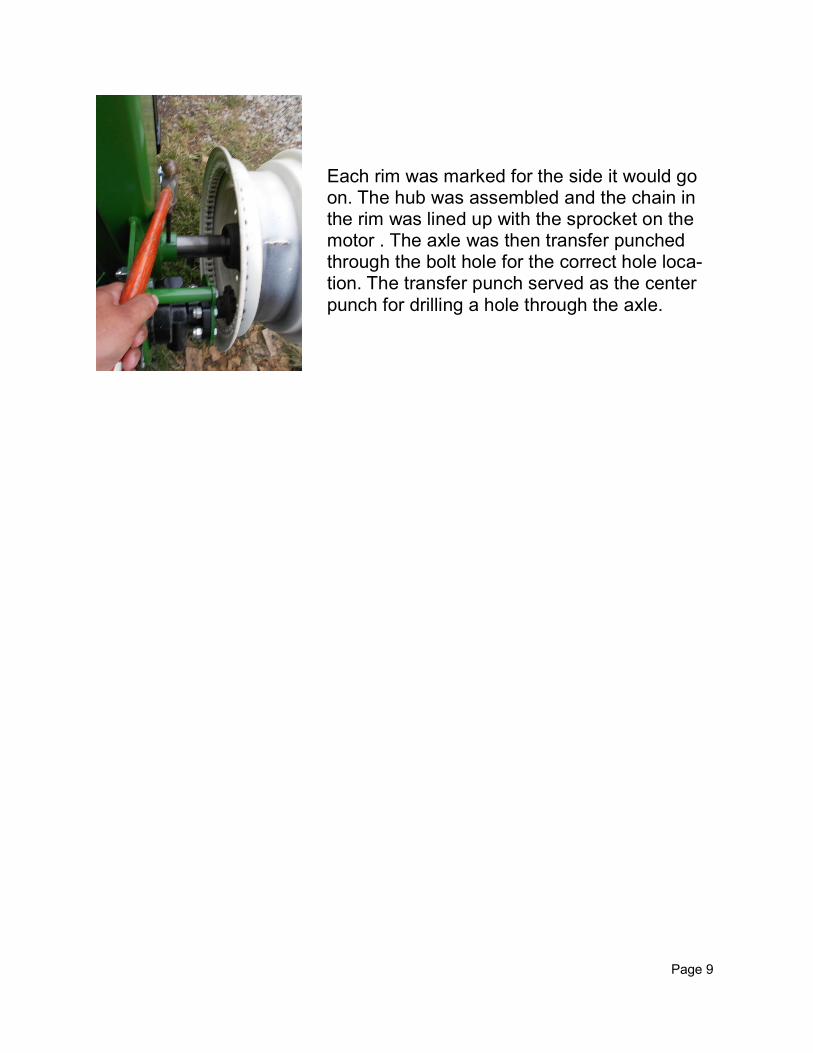
Each rim was marked for the side it would go on. The hub was assembled and the chain in the rim was lined up with the sprocket on the motor . The axle was then transfer punched through the bolt hole for the correct hole loca-tion. The transfer punch served as the center punch for drilling a hole through the axle.
Page 9
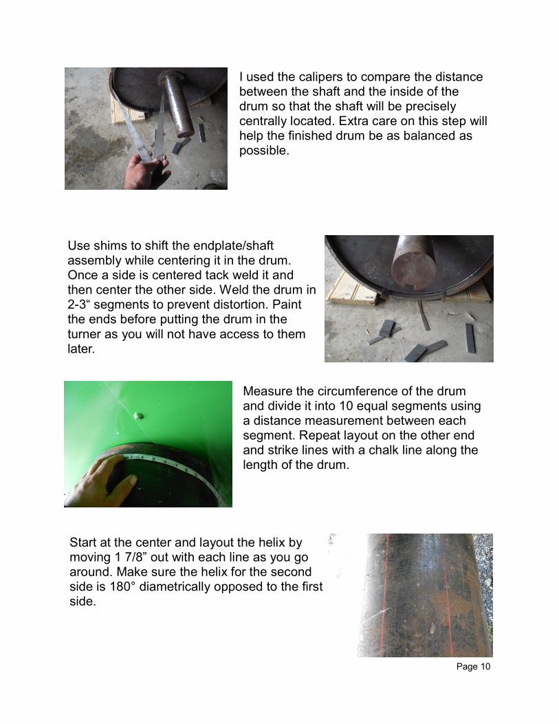
I used the calipers to compare the distance between the shaft and the inside of the drum so that the shaft will be precisely centrally located. Extra care on this step will help the finished drum be as balanced as possible.
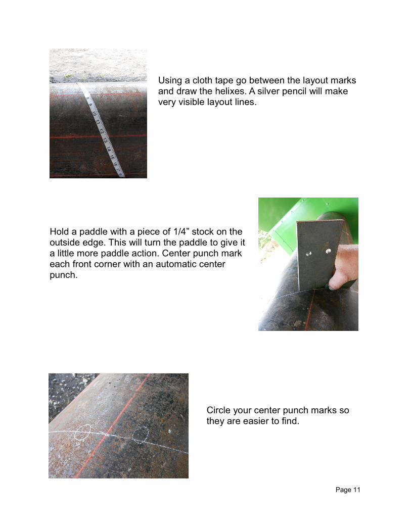
Use shims to shift the endplate/shaft assembly while centering it in the drum. Once a side is centered tack weld it and then center the other side. Weld the drum in 2-3“ segments to prevent distortion. Paint the ends before putting the drum in the turner as you will not have access to them later.
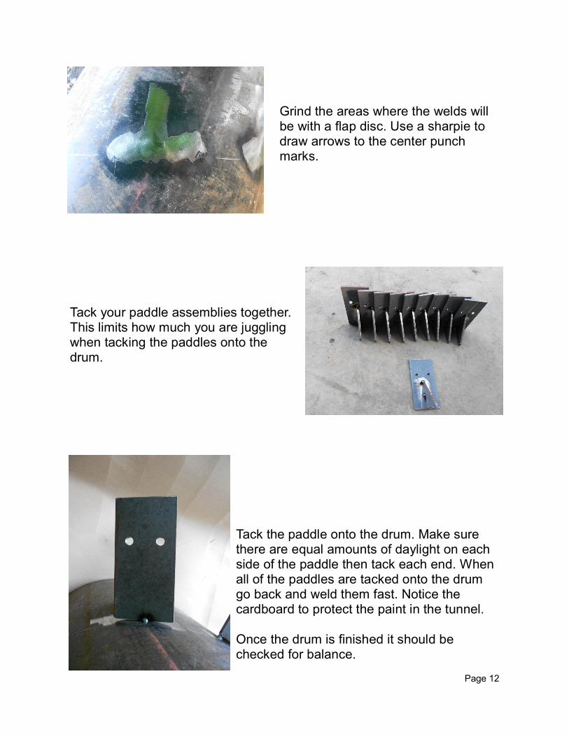
Measure the circumference of the drum and divide it into 10 equal segments using a distance measurement between each segment. Repeat layout on the other end and strike lines with a chalk line along the length of the drum.
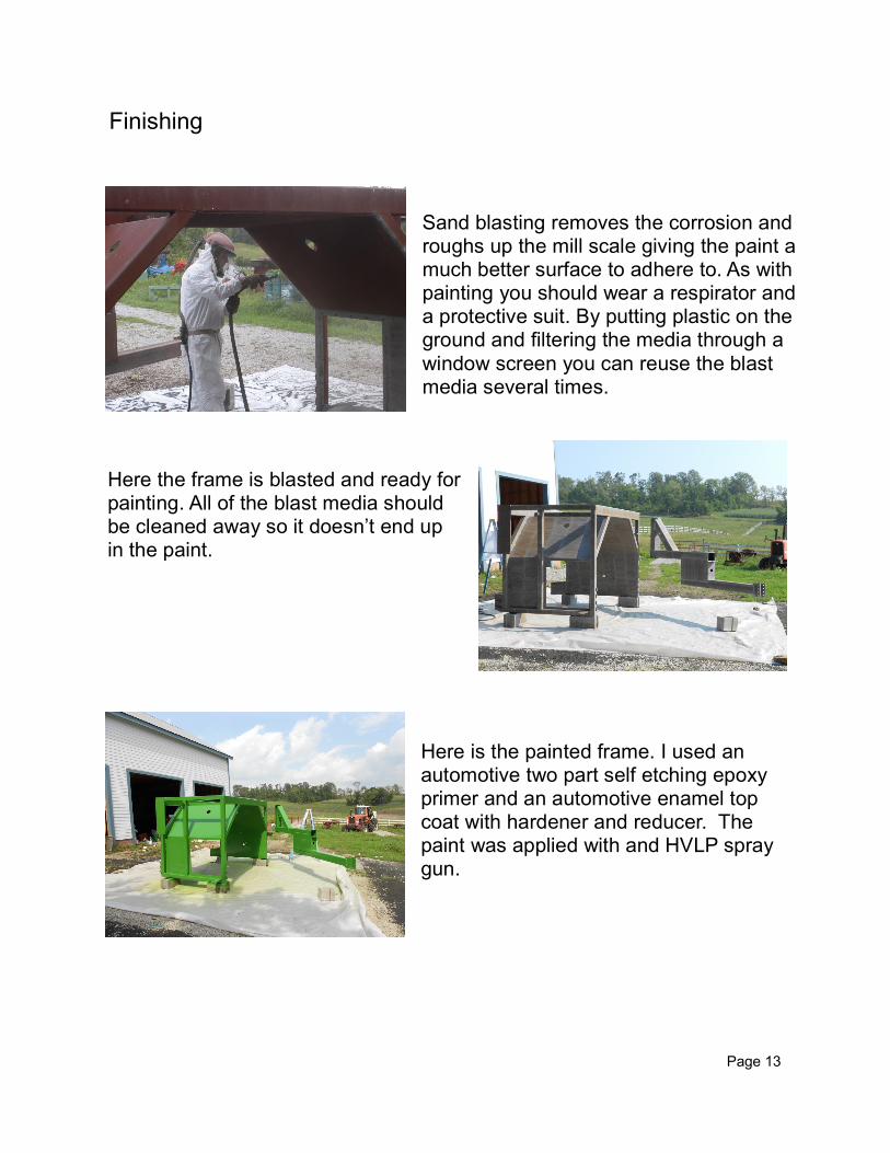
Start at the center and layout the helix by moving 1 7/8” out with each line as you go around. Make sure the helix for the second side is 180° diametrically opposed to the first side.
Page 10
Using a cloth tape go between the layout marks and draw the helixes. A silver pencil will make very visible layout lines.
Hold a paddle with a piece of 1/4” stock on the outside edge. This will turn the paddle to give it a little more paddle action. Center punch mark each front corner with an automatic center punch.
Circle your center punch marks so they are easier to find.
Page 11
Grind the areas where the welds will be with a flap disc. Use a sharpie to draw arrows to the center punch marks.
Tack your paddle assemblies together. This limits how much you are juggling when tacking the paddles onto the drum.
Tack the paddle onto the drum. Make sure there are equal amounts of daylight on each side of the paddle then tack each end. When all of the paddles are tacked onto the drum go back and weld them fast. Notice the cardboard to protect the paint in the tunnel. Once the drum is finished it should be checked for balance.
Page 12
Sand blasting removes the corrosion and roughs up the mill scale giving the paint a much better surface to adhere to. As with painting you should wear a respirator and a protective suit. By putting plastic on the ground and filtering the media through a window screen you can reuse the blast media several times.
Here the frame is blasted and ready for painting. All of the blast media should be cleaned away so it doesn’t end up in the paint.
Here is the painted frame. I used an automotive two part self etching epoxy primer and an automotive enamel top coat with hardener and reducer. The paint was applied with and HVLP spray gun.
Finishing
Page 13
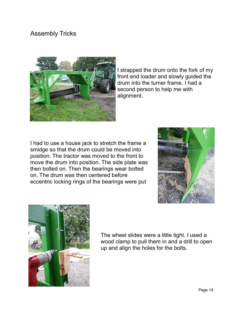
I strapped the drum onto the fork of my front end loader and slowly guided the drum into the turner frame. I had a second person to help me with alignment.
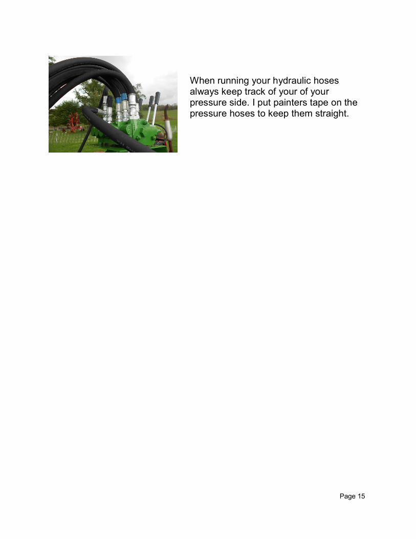
I had to use a house jack to stretch the frame a smidge so that the drum could be moved into position. The tractor was moved to the front to move the drum into position. The side plate was then bolted on. Then the bearings wear bolted on. The drum was then centered before
eccentric locking rings of the bearings were put
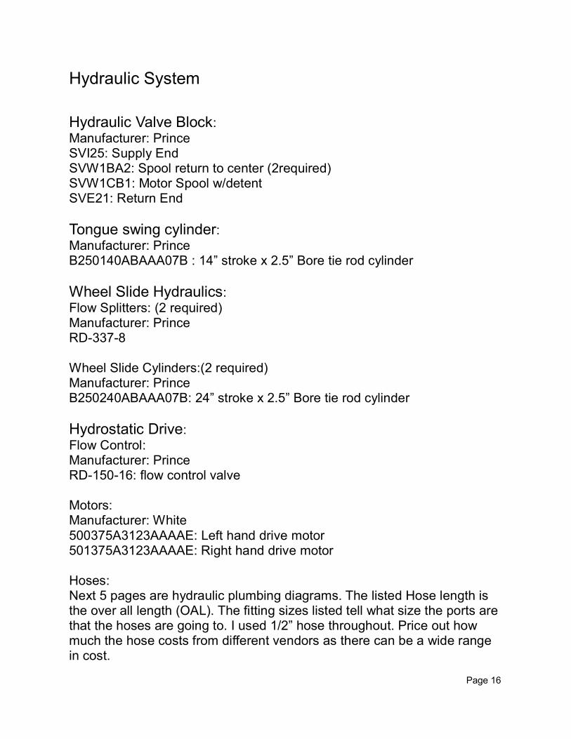
The wheel slides were a little tight. I used a wood clamp to pull them in and a drill to open up and align the holes for the bolts.
Assembly Tricks
Page 14
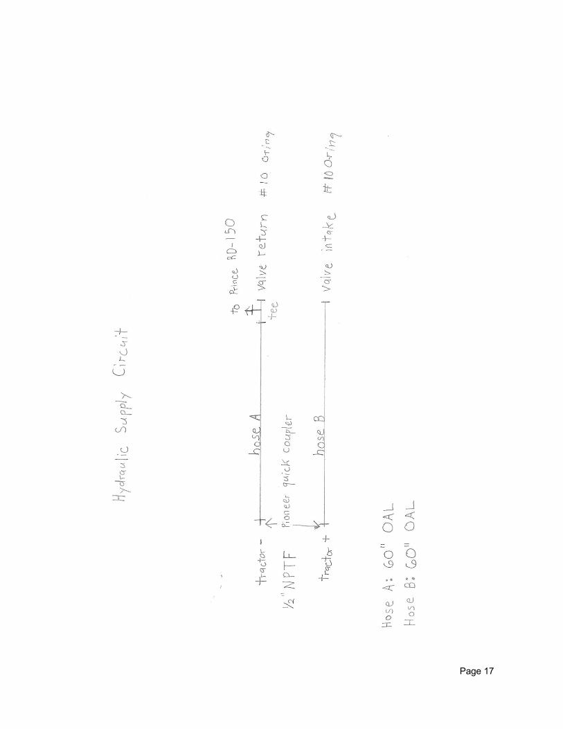
When running your hydraulic hoses always keep track of your of your pressure side. I put painters tape on the pressure hoses to keep them straight.
Page 15
Hydraulic System
Hydraulic Valve Block:
Manufacturer: Prince SVI25: Supply End SVW1BA2: Spool return to center (2required) SVW1CB1: Motor Spool w/detent SVE21: Return End
Tongue swing cylinder: Manufacturer: Prince B250140ABAAA07B : 14” stroke x 2.5” Bore tie rod cylinder
Wheel Slide Hydraulics:
Flow Splitters: (2 required) Manufacturer: Prince RD-337-8 Wheel Slide Cylinders:(2 required) Manufacturer: Prince B250240ABAAA07B: 24” stroke x 2.5” Bore tie rod cylinder
Hydrostatic Drive:
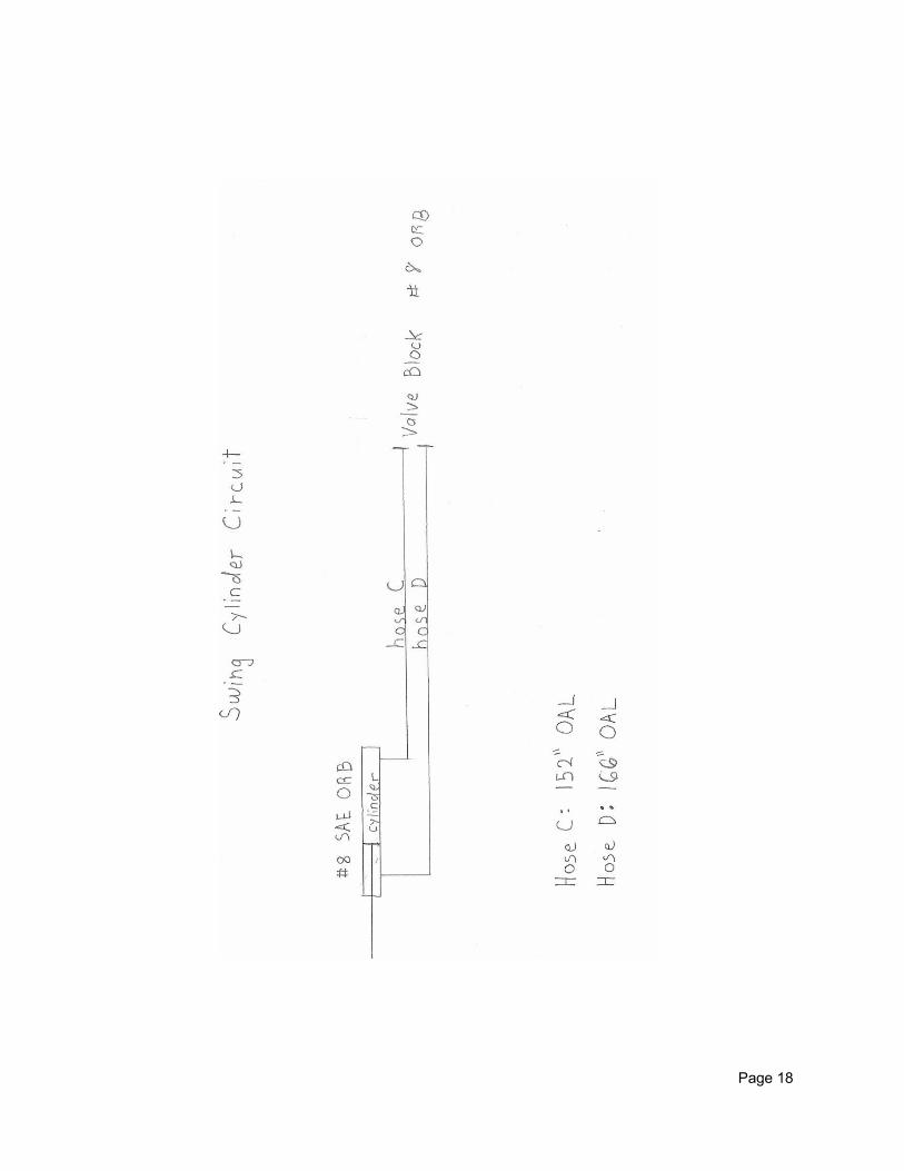
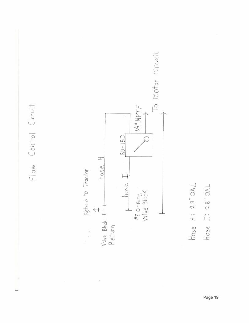
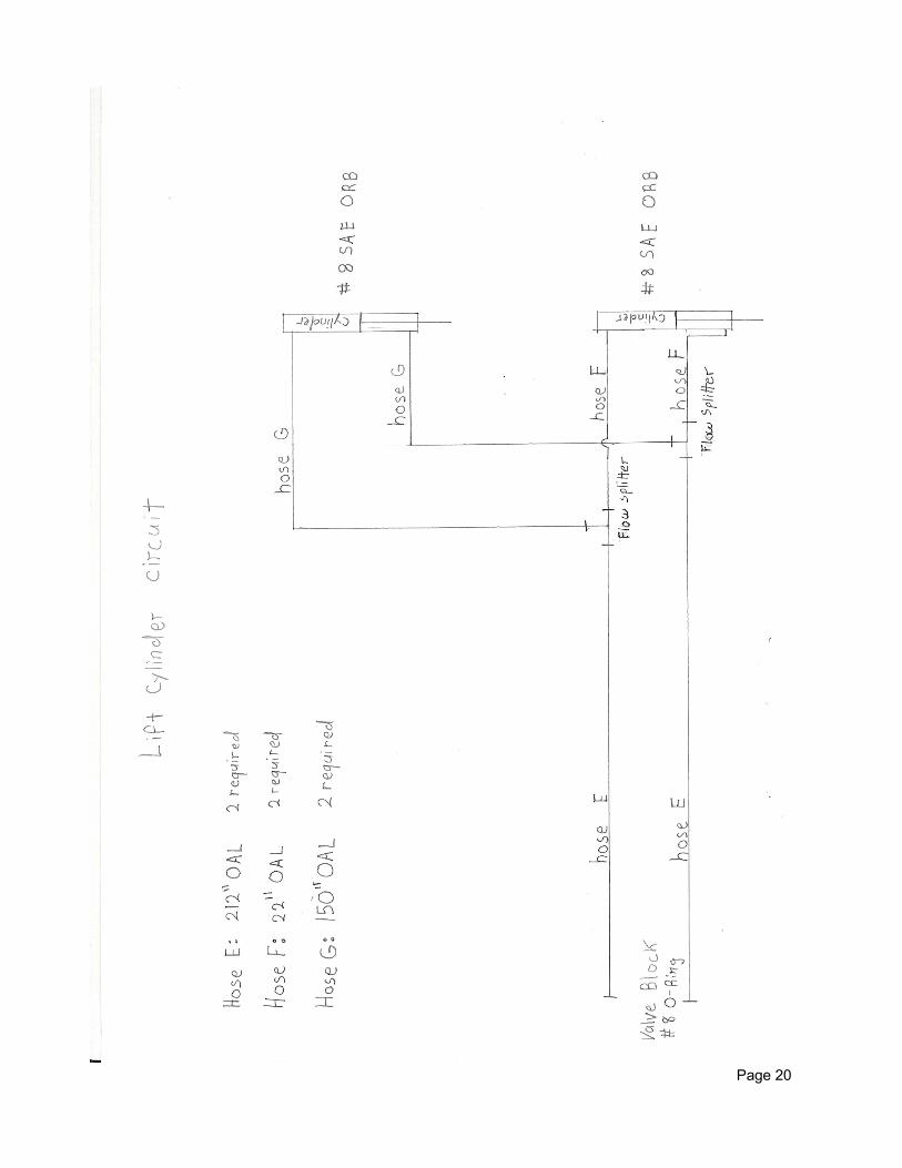
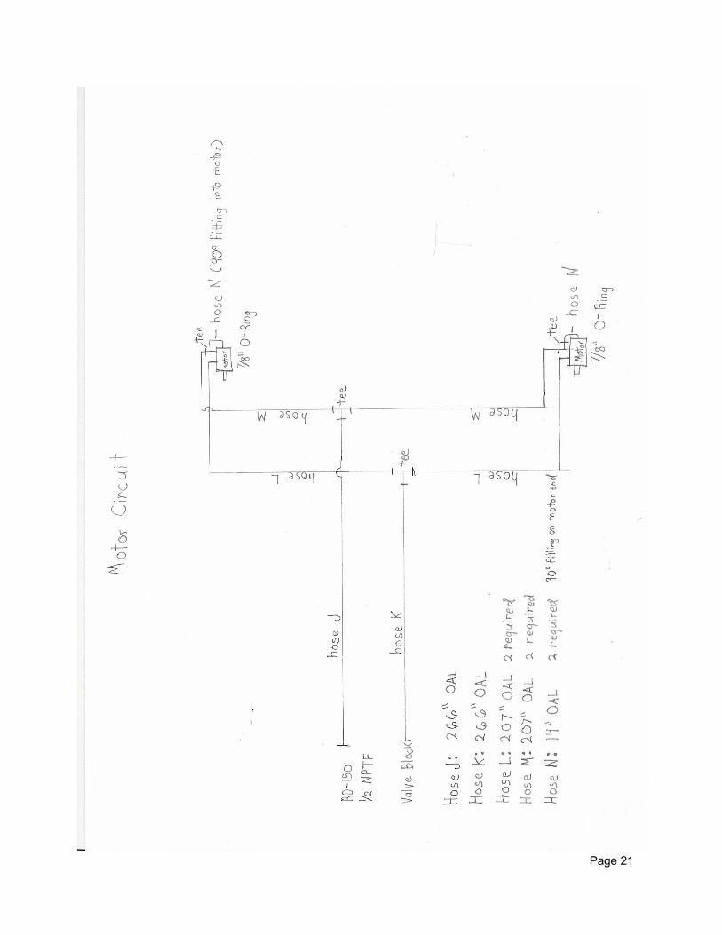
Flow Control: Manufacturer: Prince RD-150-16: flow control valve Motors: Manufacturer: White 500375A3123AAAAE: Left hand drive motor 501375A3123AAAAE: Right hand drive motor Hoses: Next 5 pages are hydraulic plumbing diagrams. The listed Hose length is the over all length (OAL). The fitting sizes listed tell what size the ports are that the hoses are going to. I used 1/2” hose throughout. Price out how much the hose costs from different vendors as there can be a wide range in cost.
Page 16
Page 17
Page 18
Page 19
Page 20
Page 21
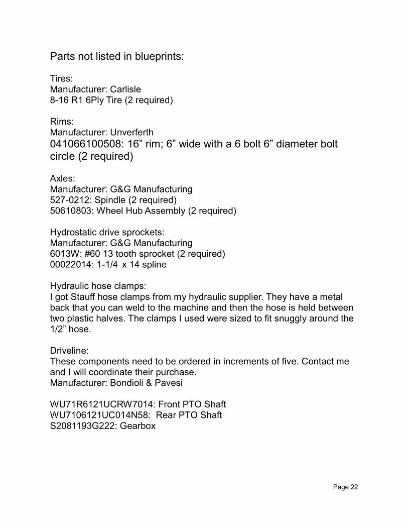
Parts not listed in blueprints: Tires: Manufacturer: Carlisle 8-16 R1 6Ply Tire (2 required) Rims: Manufacturer: Unverferth
041066100508: 16” rim; 6” wide with a 6 bolt 6” diameter bolt circle (2 required) Axles: Manufacturer: G&G Manufacturing 527-0212: Spindle (2 required) 50610803: Wheel Hub Assembly (2 required) Hydrostatic drive sprockets: Manufacturer: G&G Manufacturing 6013W: #60 13 tooth sprocket (2 required) 00022014: 1-1/4 x 14 spline Hydraulic hose clamps: I got Stauff hose clamps from my hydraulic supplier. They have a metal back that you can weld to the machine and then the hose is held between two plastic halves. The clamps I used were sized to fit snuggly around the 1/2” hose. Driveline: These components need to be ordered in increments of five. Contact me and I will coordinate their purchase. Manufacturer: Bondioli & Pavesi WU71R6121UCRW7014: Front PTO Shaft WU7106121UC014N58: Rear PTO Shaft S2081193G222: Gearbox
Page 22
Operating the compost turner: As with any farm machine you want to steer clear of moving parts and the tractor should be turned off before making any repairs or adjustments. Ground speed will be determined by the density of the material you are turning. The first couple turnings will probably be in the range of 10-20ft per minute. The gearbox on the compost turner reduces the PTO speed by approximately 50%, by adjusting the tractors throttle you can fine tune the drum speed for the material you are working. The frame should always be at least a couple of inches off of the ground. If the frame is allowed drag on the ground undue stress is transmitted through the frame and damage can result. The hydrostatic drive should be disengaged before moving the compost turner longer distances. A hydrostatic clutch disengages the motor when there is no hydraulic pressure allowing you to turn from one compost row to another without disengaging the hydrostatic drive but the transport speed should be kept under 2 miles per hour. This machine can throw material a good distance so any bystanders should maintain a safe distance between themselves and the machine. Due to the corrosive nature of manure and other material that might be in your compost you will want to lubricate and grease the machine often. Pay particular attention to the drum bearings as greasing them will flush out potential contaminants.
Page 23
Changes: This compost turner was finished towards the end of 2011. Due to the need to submit the design to complete the SARE grant I haven’t made all of the refinements that I plan on making. Here are some of the planned additions that I will be adding: -Safety shielding along the driveline -Depth stop on the wheel slides so the wheels cannot retract to far and allow the frame to drag on the ground -Gauge wheel on the front right hand corner to keep gathering paddle from digging into the ground -Rubber curtains for the front of the machine to reduce the amount of material thrown forward -Water injection system (water ports were put in the tunnel to allow for this addition) As I make and try out these additions I will put the plans online. I wish you the best of luck in building your own compost turner. If you have questions feel free to contact me. Regards, Nigel Tudor 724-587-3763 [email protected]
Page 24