Embed Size (px)
Citation preview

Fasheloum, Mohammed (1997) Investigation of drilling parameters indicators. PhD thesis, University of Nottingham.
Access from the University of Nottingham repository: http://eprints.nottingham.ac.uk/11885/1/339670.pdf
Copyright and reuse:
The Nottingham ePrints service makes this work by researchers of the University of Nottingham available open access under the following conditions.
This article is made available under the University of Nottingham End User licence and may be reused according to the conditions of the licence. For more details see: http://eprints.nottingham.ac.uk/end_user_agreement.pdf
For more information, please contact [email protected]
THE UNIVERSITY OF NOTTINGHAM
DEPARTMENT OF MINERAL RESOURCES ENGINEERING
INVESTIGATION OF
DRILLING PARAMETERS INDICATORS
by
Mohammed Fashe10um
BEng, MSc
Thesis submitted to the University of Nottingham
for the degree of Doctor of Philosophy
April 1997

Dedicated to my parents and wife
for their support and understanding
ABSTRACT
Investigation of the Drilling Performance Indicators
By
M. A. Fasheloum
BEng, MSc.
The factors which influence the performance characteristics of diamond
impregnated core bits and roller cone bits are examined, and actual field
drilling data are analysed to determine these factors.
Methods for selecting the appropriate bit type for optimised drilling are also
highlighted.
The importance of core drilling to the exploration and exploitation of the
earth's natural resources and to the integrity of engineering structures is
highlighted.
An investigation of the slim hole continuous core drilling system and its
application in the oil and gas exploration is analysed. The highly successful
integration of oilfield, mining and geotechnical exploration technologies in
a special investigation programme includes several elements which are
important in the application of slim hole methods for oil and gas exploration
are analysed. Many of the technical issues associated with a slim hole
approach have been addressed in the development and application of the
drilling, and coring equipment and systems.
The project has given an opportunity to evaluate the advantages and
disadvantages, merits and limitations for applying different drilling and
associated technologies for deep hole construction to safety.
1

ACKNOWLEDGEMENTS
First of all, I would like to extend my thanks to the Libyan MinistIy of
Education for their financial support for this research.
I am indebted my supervisor, Mr. M D. Waller, for his consistent and
continued help, guidance, encouragement, advice and generation of ideas
throughout the study and preparation of the thesis.
I would like to thank my wife, Najya, for her patience, understanding and
encouragement throughout this study.
Finally, I would also like to thank my friends, S. Aghil, A Ashore, T.
Chaff, S. Al-ameen and A Essahli for their general encouragement and
support throughout my . years in Nottingham .
.. il
CONTENTS
Page
Abstract .... · ............................................................................................ i
Ackn.owledgements ............................................................................... ii
List of Figures ...................................................................................... 'Vii
List of Tables ....................................................................................... xii
Chapter 1 INTRODUCTION TO DRILLING ................................. 1
1.1 Aim of the Research .......................................................... 1
1.2 Principles of Drilling ......................................................... 2
1.3 Dependent Variables ......................................................... 4
1.3.1 Penetration Rate ...................................................... 4
1.3.2 Torque ..................................................................... 4
1.3.3 Flush Medium Pressure ........................................... 5
1.3.4 F onnation Pore Pressure .......................................... 7
1.4 Independent Variables ....................................................... 8
1.4.1 Bit Load ................................................................... 8
1.4.2 Rotational Speed ...................................................... 9
1.4.3 Drilling Fluid ........................................................... 10
1.4.4 Hydraulic Horsepower ............................................. 11
1.4.5 Bit Type .................................................................. 12
Chapter 2 BIT SELECTION AND EV ALUATION ........................ 14
2.1 Introduction ...................................................................... 14
2.2 Bit Types Available .......................................................... 15
2.2.1 Drag Bits ................................................................. 16
2.2.2 Polycrystalline Diamond (PDC) Bits ....................... 17
2.2.3 Rolling Cutter Bits ................................................... 20
ill
2.2.4 Core Bits ................................................................. 23
2.2.4.1 The Surface Set Natural Diamond Core Bit .. 23
2.2.4.2 Impregnated Diamond Core Bits .................. 26
2.2.4.3 Poly crystalline Diamond Compact
(PDC) Core Bits ........................................... 31
2.3 Bit Selection and Evaluation ............................................. 32
2.3.1 Cost Per Interval Drilled .......................................... 35
2.3.2 Drilling Specific Energy .......................................... 37
2.3.3 Bit Dullness ............................................................. 38
2.3.3.1 Grading Tooth Wear. ................................... 39
2.3.3.2 Grading Bearing Wear. ................................. 40
2.3.3.3 Grading Gauge Wear .................................... 41
2.3.4 Variable Information Analysis ................................. 42
Chapter 3 SLIM HOLE CONTINUOUS CORE DRILLING ......... 47
3. 1 Introduction ...................................................................... 47
3.2 The Evolution of Continuous Coring Slim Hole System .... 47
3.3 Reasons for Slim Hole Continuous Core Drilling .............. 49
3.4 Evolution of Continuous Coring Slim Hole System
for Oil and Gas Exploration and Exploitation Drilling ....... 51
3.5 Continuous Coring Rigs .................................................... 53
3.5.1 Rig Designs ............................................................. 54
3.5.2 Mining Drilling Equipment ...................................... 55
3.6 Drilling Operations ........................................................... 55
3.6.1 Drilling Fluids Hydraulics ....................................... 56
3.6.2 Drill Rods ................................................................ 59
3.6.3 Cementing ............................................................... 60
3.6.4 Bits .......................................................................... 60
3.6.5 Well Control ............................................................ 61
3.6.6 Core Retrieval and Processing ................................. 61
IV
3.7 Challenges to Oilfield Drilling .......................................... 63
3.8 Considerations for Oilfield Drilling ................................... 64
Chapter 4 CORE DRILLING ........................................................... 65
4.1 Introduction ...................................................................... 65
4.2 Field Progratllffie ............................................................... 67
4.2.1 Geotechnical Investigation Drilling Progratllffie ....... 67
4.2.1.1 Borehole Design ........................................... 69
4.2.1.2 Drilling Rigs and Equipments ....................... 72
4.2.1.3 Wireline Coring System ............................... 75
4.2.1.4 Drilling Fluids .............................................. 81
4.3 Hole Opening and Continuous Coring ............................... 83
4.4 Well Control ..................................................................... 86
4.5 Core Handling ................................................................... 89
4.6 Logging and Testing Progratllffie ....................................... 90
Chapter 5 ANALYSIS OF THE DRILLING RESULTS ................ 92
5.1 Introduction ....................................................................... 92
5.2 Methodolog}' ..................................................................... 93
5.3 Description of Rig and Wireline Coring System ................ 94
5.3.1 Sensors .................................................................... 95
5.3.2 Hole Opening .......................................................... 97
5.3.3 Coring ..................................................................... 97
5.5 Oilfield Drilling Operation ................................................ 98
5.6 Rotation Speed (RPM) ...................................................... 99
5.7 Weight On Bit (WOB) ...................................................... 108
5.8 Bit Hydraulics ................................................................... 121
Chapter 6 DISCUSSION OF RESULTS .......................................... 124
6. 1 Introduction ...................................................................... 124
v
6.2 Rotational Speed ............................................................... 124
6.3 Weight On Bit. .................................................................. 126
6.4 Bit Hydraulics ................................................................... 129
6.5 Core Bit Design And Performance At Sellafield ................ 130
6.6 Operational Performance ................................................... 134
Chapter 7 Conclusions and Recommendations ................................. 137
7.1 Conclusions ...................................................................... 137
7.2 Recommendations ............................................................. 141
References ........................................................................................... 143
VI
List of Figures
Page
Figure 1.1. Drilling variables associated with rotary drilling ................ 3
Figure 2.1. Example of polycrystalline diamond cutter bit ................... 18
Figure 2.2. Wear characteristics of milled-tooth bit. ............................ 22
Figure 2.3. Various tungsten carbide insert cutters used
in roller cone bit ................................................................ 22
Figure 2.4. An illustration of a typical impregnated
diamond core bit ................................................................ 28
Figure 2.5. An illustration of the essencial components of
an impregnated diamond core bit. ...................................... 28
Figure 2.6. Initial crown profiles of impregnated diamond
core hit .............................................................................. 29
Figure 2.7. Tooth wear guide chart for milled-tooth bits ...................... 40
Figure 2.8. Bearing grading guide for roller cutter bits ......................... 41
Figure 2.9. Methodology for bit selection ............................................ 46
Figure 3.1. A typical mining core drilling system ................................ 52
Vll
Figure 3.2. A schematic diagram of a typical slim hole
drilling and casing programme ........................................... 59
Figure 3.3. Wireline coring assembly .................................................. 62
Figure 4.1. A typical borehole design scheme for
worst case scenario ............................................................ 70
Figure 4.2. Actual borehole configurations .......................................... 71
Figure 4.3. A typical arrangement for technical casing ........................ 73
Figure 5.1. Sensors .............................................................................. 96
Figure 5.2. Rotational speed (RPM) Vs Rate of penetration for
Security, S86F tri-cone (8.5") bit type while drilling
St Bees sandstone, England ............................................... 101
Figure 5.3. Rotational speed Vs Rate of penetration, for Security
-S86F-(8.5") tri-core bit type, while drilling Beda
sandstone, Libya ................................................................ 102
Figure 5.4. Rotational speed Vs Rate of penetration for Security
M44NG (17.5") tri-cone bit type while drilling
Gialo East Shale, Libya ..................................................... 103
Figure 5.5. Rotational speed and weight on bit Vs Wear, for
Security -S86F- (8.5"). tri-cone bit type, while drilling
Dahra shales, Libya ........................................................... 104
V111
Figure 5.6. Rotational speed and Weight on bit Vs Tooth wear,
for HTC -R- (17.5") tri-cone bit type, while drilling
Beda Sandstone, Libya ...................................................... 105
Figure 5.7. Rotational speed and Weight on bit Vs Tooth wear,
for Security M44NG- (17.5") tri-cone bit type
while drilling Gialo East Shales, Libya .............................. 106
Figure 5.8. Weight on bit and Rotational speed Vs
Tooth wear, for Security-S33S- (17.5") tri-cone bit type,
while drilling Gir Dolanny Shales, Libya ........................... 107
Figure 5.9. Weight on bit Vs Rate of penetration, for Eastman,
B-9 (6.25"), IMP Dimond core bit type while
drilling St Bees Sandstone, England .................................. 109
Figure 5.10. Rate of penetration Vs Tooth wear, for Eastman
B-9 (6.25") IMP Dimond core bit type while
drilling St Bees sandstone, England ................................... 110
Figure 5.11. Weight on bit Vs Rate of penetration of a Dimatic
M7S-1 (6.25"). IMP Diamond core bit type
whil e drilling Borrowdale Volcanics, England ................... 111
Figure 5.12. Rate of penetration Vs Bit condition for Dimatic
(6.25") IMP Dimond (M7S-1) core bit while
drilling Borrowdale Volcanic rocks, England .................... 112
IX
Figure 5.13. Weight on bit V s Teeth Wear for a Dimatic
M7S-1 (6.25"). IMP Diamond core bit type
while drilling Borrowdale volcanics, England ................... 113
Figure 5.14. Weight on bit Vs Rate of penetration, for
Security, S86F tri-cone (8.5") bit type while
drilling St Bees sandstone, England ................................... 114
Figure 5.15. Weight on bit Vs Rate of penetration, for
Security -S86F- (8.5") tri-cone bit type, while
drilling Dahra shales, Libya .............................................. 115
Figure 5.16. Weight on bit Vs Wear, for Security -S86F
(8.5") tri-cone bit type, while drilling
Dahra shales, Libya ........................................................... 116
Figure 5.17. Rotation time Vs Wear, for Security -S86F
(8.5") tri-cone bit type, while drilling
Dahra shales, Libya ........................................................... 117
Figure 5.18. Weight on bit Vs Rate of penetration, for
Security M44NG (17.5") tri-cone bit type while
drilling Gialo East Shale, Libya ......................................... 118
Figure 5.19. Weight on bit Vs Tooth wear, for Security
-M44NG (17.5") tri-cone bit type while drilling
Gialo East Shales, Libya ................................................... 119
x
Figure 5.20. Weight on bit Vs Rate of penetration, for
Security -S86F- (17.5") tri-cone bit type, while
drilling Gir Dolanny Shales, Libya ................................... 120
Figure 5.21. The effect of weight on bit Vs the rate of
penetration for a range of different hydraulic
horsepower values ............................................................. 122
Figure 5.22. The effect of flush flowrate on the penetration
rate in various rock types ................................................... 123
Figure 6.1. Tripping time of singles rig V s triples rig during
coring and testing .............................................................. 135
Xl
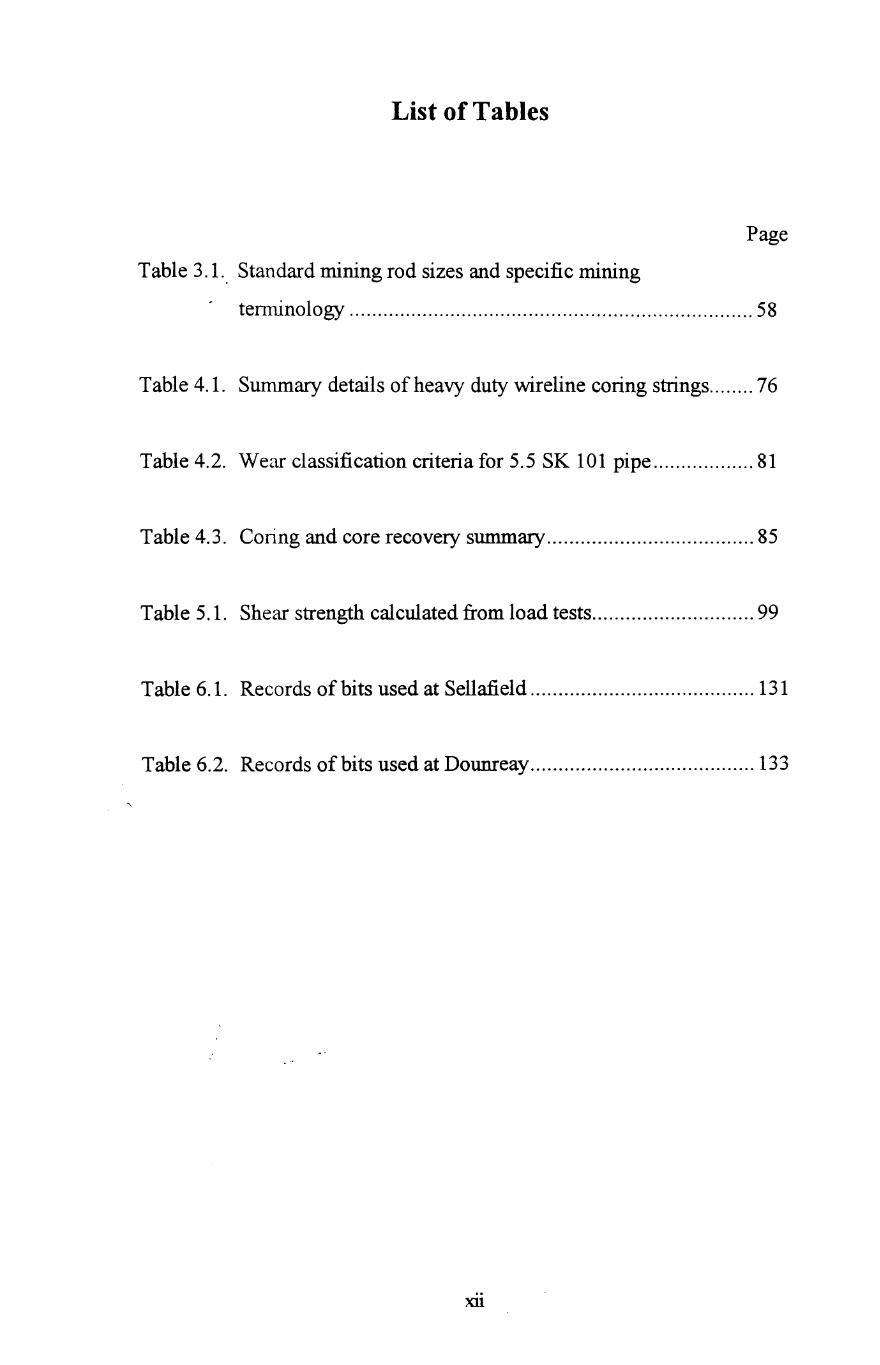
List of Tables
Page
Table 3.1. Standard mining rod sizes and specific mining
temlinology ........................................................................ 58
Table 4.1. Summary details of heavy duty wireline coring strings ........ 76
Table 4.2. Wear classification criteria for 5.5 SK 101 pipe .................. 81
Table 4.3. Coring and core recovery summary ..................................... 85
Table 5.1. Shear strength calculated from load tests ............................. 99
Table 6.1. Records of bits used at Sellafield ........................................ 131
Table 6.2. Records of bits used at Dounreay ........................................ 133
Xl1
Chapter One
INTRODUCTION TO DRILLING
1.1 Aim of the Research
Drilling bits were predominantly investigated in the early stages of drilling
research at the University of Nottingham. Initial research on drilling bits
was carried out by Ambrose, 1987, who analysed the perfonnance of
impregnated core bits. In this research, a number of different rock samples
were drilled with a variety of different bits. Amongst the laboratory test
results produced were graphs of penetration rate against bit wear rate.
Monitoring and logging of the drilling parameters was conducted during the
drilling operations.
Initial laboratory tests on Syndrill non-core polycrystalline diamond
compact (PDC) bits in coal measures rocks were conducted for rockbolt
holes (Singh et al., 1989 and AI-Ameen et aI., 1992). Substantial
modifications in the laboratory drilling rig and electronic circuits were
carried out by Waller, 1991. The automatic optimisation of drilling
perfonnance using a computerised method was undertaken by Rowsell,
1991, and the design and development of the drilling optimisation scheme
were described. Syndite PDC non-core bits were tested in coal measures
rocks by Shah, 1991. In this research, nearly all results were graphs of
operating parameters against bit advance per revolution.
More study of new design of Syndax3 thermally stable poly crystalline
diamond compact core bits, was conducted by Ersoy, 1995. His study
1
C1u:tpter 1 Introduction to Drilling
included an analysis of the microscopic wear mechanisms, and the influence
of rock parameters on the performance of PDC.
The purpose of the present study is to contribute to the understanding of
drilling parameters and determine their affect on the performance of both
tri-cone and impregnated core bits in field conditions. To highlight the
importance and applications of core drilling. Also to investigate the options
and challenges of applying the slim hole continuous core drilling system
for oil and gas explorations.
1.2 Principles of Drilling
The wide variations in drilling conditions encountered under field
conditions make it difficult to develop general rules of operation for
maximum drilling efficiency. Field experience usually provides the basis
for operations in a particular area, but testing often is too costly and
experience too late. Consequently, a method for determining optimum
drilling techniques and parameters for any particular drilling condition, with
a minimum of engineering effort and drilling experience, is greatly needed.
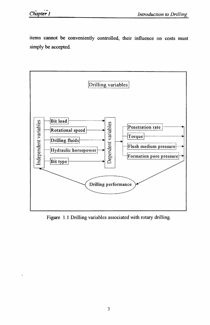
The drilling parameters, or variables, associated with rotary drilling have
been analysed and divided in two groups as independent and dependent
parameters as shown in figure 1.1, (Barr and Brown, 1983, Ambrose, 1987,
Shah, 1992). The independent variables are those which can be directly
controlled by the drilling rig operator and dependent variables are those
which represent the response of the drilling system to the drilling operation.
There are, of course, many factors other than those discussed here that
effect drilling efficiency and footage cost. These include such factors as
formation hardness, abrasiveness of fonnation and well depth. As these
2
~
Cliapter 1 Introduction to Drilling
items cannot be conveniently controlled, their influence on costs must
simply be accepted.
IDrilling variables I
r/l Bit load r/l do) - do) ..0 ~
ro Rotational speed ..0 .- ro '-ro '-:> ro
:> ....... Drilling fluids c ....... do) c Flush medium pressure '"'d do)
c Hydraulic horsepower '"'d do) C 0... do)
YFormation pore pressurel do) 0... "'0 do)
c Bit type 0 -
Figure 1.1 Drilling variables associated with rotary drilling.
3

C1iJjV"] , p;;-r Introduction to Drilling
1.3 Dependent Variables
The dependent variables associated with rotary drilling represent the
response of the drilling system to the imposed conditions and are the
penetration rate of the bit, the torque and the flush medium pressure.
1.3.1 Penetration Rate
The rate of penetration (ROP) of the rotary bit through rock, is expressed in
units of distance per unit time. The rate of penetration is considered as one
of the primary factors which affect drilling costs and hence it is given a
prior consideration when planning for optimised drilling.
The subject of drilling rate has been extensively analysed from both the
theoretical standpoint and the experimental standpoint with the objective of
maximising drilling rate and improving operating efficiencies (Lummus,
1969, 1970, Eckel, 1967, Huff and Varnado, 1980, Kelsey, 1982, Holester
and Kipp, 1984, Ambrose, 1987, Warren and Armagost, 1988, Waller,
1991, and Shah, 1992). Miniature drill bits have been widely used in the
laboratory to study combinations of independent drilling variables, as well
as to relate drilling rate to measurable rock properties. The determination of
the rate of penetration is one of the most important objectives, and is
therefore considered and presented in detail in this thesis. Collectively,
contributions to the understanding of these factors on the penetration rate
has been greatly exploited in an effort to drill faster and more economically.
1.3.2 Torque
Torque is defined as the force required to tum the drill rod, which leads to
the bit rotating against the resistance to the cutting and friction forces.
4
\..,. TlUPU:, .I. Introduction to Drilling
In shallow boreholes, the torque is the result of the forces resisting the
cutting and shearing action generated at the bit/rock contact by the rotation
of the bit. In deep boreholes, additional torque is required to overcome
additional forces between the drill rods and the flushing medium. Torque is
usually measured in Nm or lb-ft.
The torque required to rotate a bit is of interest for several reasons. First, it
may give information about the formation being drilled and/or the condition
of the bit. Second, bit torque exerts a significant influence on the "bit walk"
experienced in directional wells. Finally, a prediction of bit torque may be
useful in matching a bit and mud motor for optimal performance.
Several authors, (Paone et al., 1969, Clark, 1979, 1982, Warren, 1983,
Ambrose, 1987, Waller, 1991 and Shah, 1992) have presented theoretical
bit torque relationships derived by testing many types of rocks with coring
and non-coring bits, and found that the penetration rate increases with
torque and a critical value of torque exists below which penetration does
not occur. The torque relationship for a given bit is determined largely by
the applied weight on bit and the depth of penetration of bit indenters.
1.3.3 Flush Medium Pressure
Drilling fluids in the wellbore can be in either a static or dynamic state.
The static system occurs when the fluid stands idle in the well. The
dynamic state occurs when the fluid is in motion, resulting from pumping or
pipe movement. The static pressure of a column of fluid pressure is known
as "hydrostatic pressure" which is an essential feature in maintaining
control of well and preventing kicks or blowouts. The hydrostatic pressure
5
Chapter 1 Introduction to Drilling
of a fluid column is a function of the mud weight or density and the true
vertical well depth.
The rate of penetration (ROP) obtained while a well is drilled generally
shows a steady decline as well depth increases. The causes of the reduction
in ROP with depth can be divided into two categories:
1) a processes that affects the unbroken rock, and
2) processes that act on the rock once it is broken into chips.
The chip removal process is probably more important in terms of total effect
on ROP, but the strengthening of the unbroken rock is not negligible.
Although several authors (Garnier, 1959, Feenstra, 1964 and Warren, 1984)
have discussed in considerable detail the chip removal process.
This reduction of the ROP is often attributed to increasing "differential
pressure", increasing hydrostatic head, increasing in-situ stresses,
decreasing porosity with depth, and chip hold-down. For the flush medium
to flow down the drillstring and up the annulus, a pressure difference must
exist between the flush descending within the drill rods and that ascending
in the annulus outside the drill rods. The pressure required to cause flow
has to counteract the difference in the fluid densities, due to suspended rock
particles and has to overcome the frictional resistance to flow. Increasing
the ROP of the bit increases the weight of suspended rock particles and
hence the differential fluid pressure. Pump pressure is used to overcome
the frictional resistance and weight imbalance of suspended rock particles.
Increasing the fluid flow rate also results in an increase in the differential
pressure.
6
Chapter 1 Introduction to Drilling
1.3.4 Formation Pore Pressure
The properties of the rock being drilled can, from the definition of drilling
variables discussed in the introduction, be considered as an independent
variable, the drilling rig operator has no control over it, as they help
determine the response to the drilling operation rather than being a response
in itself.
Formation pore pressure can be major factor affecting drilling operations
especially in deep wells. An operator planning a well needs some
knowledge of overburden and formation fluid pressure in order to select the
necessary hydrostatic or drilling fluid pressure. If this pressure is not
properly evaluated, it can cause drilling problems such as lost circulation,
blowouts or kicks, stuck pipes, hole instability and excessive costs.
The formation pressure is related to pore spaces of the formations which
contain fluids such as water, oil or gas. The overburden stress is created by
the weight of the overlying rock matrix and the fluid-filled pores. The rock
matrix stress is the overburden stress minus the formation pressure.
Formation fluid or pore pressures are usually categorised as normal,
subnormal and abnormal or over pressured. When formation pore pressure
is approximately equal to hydrostatic pressure of drilling fluid for a given
vertical depth, formation pressure is described to be normal. When the
formation is opened to the atmosphere during drilling, a column of drilling
fluid from the ground surface down to the formation depth (hydrostatic
pressure) would balance the formation pressure. If the formation pressure is
less than that of the hydrostatic pressure, then it is called subnormal
formation pressure. Formations with pressure higher than hydrostatic are
encountered at various depth in many areas. These formations are referred
to as being abnormally pressured or over pressured. Generally, abnormal
7
Chapter 1 Introduction to Drilling
pore pressures are associated with fluids trapped within the pore spaces of
rocks by low permeability barriers such as salt domes, folds or faults.
Numerous authors have demonstrated the severe reduction in ROP with
different rotary bits as the borehole pressure increases. (Garnier and van
Lingen, 1959, Cunningham and Eenink, 1959, Black, et al., 1 977,
Bourgoyne et al., 1986).
1.4 Independent Variables
The independent variables are the drilling fluids, bit load, the bit rotational
speed, bit type and the hydraulics horse power.
1.4.1 Bit Load
A range of terms are used to describe this parameter such as thrust, bit load,
bit pressure, axial load or axial pressure, and weight on bit (WOB). Weight
on bit is a basic controllable drilling variable. A bit load needs to be
applied for the bit to drill. The amount of bit load applied in practice
depends on many factors, which include the type of bit, the bit diameter, the
presence of discontinuities in the rock mass, the type of drilling rig and
equipment etc., but it is primarily governed by the physical properties of the
rock being drilled. This is because the bit penetrates the rock when the
pressure exerted by the bit indenters exceeds the strength of the rock and
feeds it forward. The weight on bit requirement depends on the size and
geometry of the bit and the resistance (strength) of the rock. The rig must
be capable of producing the required WOB with sufficient stability for
drilling a given hole size with a selected bit size.
8
Chapter 1 Introduction to Drilling
A number of authors have conducted tests to investigate the effect of WOB
on drilling performance, (Paone et aI., 1969, Schmidt, 1972, Clark, 1979,
1982, Osman and Mohammed, 1992, Speer, 1958). These investigations
showed that low WOB results in free rotation of the bit, which produces
low rate of penetration and poor chip formation, excessive bit wear because
of the bit sliding over the surface of the rock. High WOB, above a critical
value leads to the drill machine stalling. Maximum ROP is achieved when
optimum value of WOB is reached, after which, an increase in WOB gives
little increase in the penetration rate. The limiting value of WOB is
determined by the torque capacity of the equipment. The above researchers
have also concluded that the optimum WOB gives high penetration rate and
low bit wear. Consequently, each drill has a characteristic optimum WOB
for maximum penetration which corresponds to good indentation at the bit
rock interface and to optimum indexing. The optimum WOB also depends
on the other optimal drilling conditions.
1.4.2 Rotational Speed
The drilling process consists of a series of fracture generating events. The
drilling rate for a constant depth of bit indenter, penetration will depend on
the bit rotational speed. The relationship between rotational speed (RPM)
and rate of penetration (ROP) has been investigated by the previously
mentioned authors. It has been confirmed that generally there is a near
linear relationship between the two parameters in soft rocks. Drilling rate is
not proportional to rotary speed in medium and hard formations due to the
requirement that some finite time is required for fracture development in
hard rocks.
For a given penetration rate to be achieved, the bit weight and rotational
speed should be continuously maintained, and adequate flush flow
maintained to ensure rock cuttings removal from the hole. However, the
9
Chapter 1 Introduction to Drilling
increase in bit rotary speed result in greater wear on the bit and may also
cause chatter, micro-chipping and cracking of cutting indenters or teeth of
the bit. The rotational speed may also be restricted by the stability of the
rig and the drill rods.
1.4.3 Drilling Fluid
The term "drilling fluid" includes all of the compositions used to remove
cuttings from the borehole. An effective drilling process can only be
continued, when the bottom of the hole is maintained clean. This is
achieved by a sufficient flow flushing medium, which can be; air, water, oil,
oil/water emulsion, mud or foam (Moore, 1958). Drilling rate is proved to
be faster and bit life longer with air as compared to water or mud. Drilling
was originally performed with air or water as a drilling medium used to cool
the bit and flush away the drill cuttings. As these two media were usually,
easily available, cheap and satisfactory for the shallow boreholes and hard
formations being drilled at that time. Through the years many additional
requirements have been placed on the drilling fluid. To satisfy these
demands, as boreholes began to be drilled deeper, and especially with the
rapid development of oil well drilling in soft and often caving sedimentary
formation, the composition has been modified greatly from the air or water
that was originally used.
To overcome problems such as borehole instability, a drilling fluid called
mud was developed, consisting of water and bentonite clay. Mud has a
number of properties such as its caking ability, its higher density, viscosity
and its thixotropic properties, which make it particularly suitable for drilling
deep and soft formations that would otherwise prove difficult to drill.
However, water is still commonly used as a flushing medium and mud used
only where necessary due to the drawback of the large quantities of
10
Chapter 1 Introduction to Drilling
bentonite needed to make the mud and the extra equipment, which result in
extra costs (Gray and Young Jr, 1973).
Although at the present time numerous brand names of drilling fluids are
commercially available for a range of purposes and conditions, the main
function of all these fluids is the successful, speedy and satisfactory
completion of the well. The selection of the type of drilling fluid is largely
determined by the expected hole conditions. The adjustment of drilling
fluid properties is intimately related to the well depth, casing programme
and the drilling equipment.
1.4.4 Hydraulic Horsepower
Hydraulics has long been recognised as one of the most important
considerations in the design of drilling programmes. Improved bottom hole
cleaning afforded by jet rock bits and high levels of bit hydraulic
horsepower permit the use of the most effective combination of weight and
rotary speed and minimises the risk of bit fouling. These benefits became
apparent during the early days of jet bit drilling as contractors began to
search for ways to maximise the effectiveness of their hydraulic systems.
The results are extended bit life and faster penetration rates.
An increasing number of commercial bits are becoming available with
interchangeable nozzles, providing the flexibility of rig-site hydraulics
optimisation. With these interchangeable nozzles, the hydraulic energy (or
power) of the drilling fluid that is dissipated across the bit face can be
adjusted to match that portion of the rig's hydraulic power that is available
for the bit after other system losses have been considered. (Kendal and
Goins, 1960; Randall, 1975, Tibbitts et al., 1979, Hollester and Kipp, 1984,
II
Chapter J Introduction to Drilling
Kelly and Pessier, 1984). The degree to which drilling rate was affected by
bit hydraulic horsepower depends on the rock/drilling-fluid combination.
1.4.5 Bit Type
Achieving the highest rate of penetration with the least possible bit wear is
the aim of every drilling engineer when selecting a drilling bit. Because
formation properties and bit type are the largest factors that affect
penetration rate, and obviously, formation properties cannot be changed
before drilling and thus selection of the correct bit type is of major
importance in achieving high rates of penetration.
The rapid evolution of the roller-cone bits and the perfection of techniques
for manufacturing diamond-impregnated core bits, have profoundly
influenced recent drilling practices. Bit footage and consequently, footage
costs, have dramatically improved as a result of these developments.
Advances in metallurgy and heat-treatment techniques and the development
of lubricated sealed bearings have made possible the widespread
introduction of journal bearings. The bearings have significantly prolonged
bearing life. Milled-tooth cutting structures are being replaced by shaped
inserts of carbide composition, reducing the tooth abrasion of these cutting
elements. The longer inserts make high penetration rates possible well
within the life of the bearings, allowing lower over-all drilling costs to
offset the increase in bit expenses. Cone offset and other features of milled
tooth bits have been incorporated into the design of the carbide insert bit
(Estes, 1971). The use of jets in the bit fluid bath has substantially
improved hole cleaning and chip removal, and the use of jets in planned
hydraulics programmes has become widespread (Eckel, 1967, Kendall,
1960 and Rabia, 1985). A variety of bit types and sizes are now available
for rocks of varying abrasiveness, strength and drilling types.
12
Chapter 1 Introduction to Drilling
Bit selection, like the selection of the correct WOB, RPM and hydraulics, is
dependent upon a degree of trial and error. Unfortunately, there is no
foolproof method of selecting the best available drilling bit for the
formations to be drilled. The aim of any bit selection programme is to
reduce the trial and error to a minimum. There are many proposed methods
for bit selection and often more than one is used before reaching a decision.
Bit selection methods include:
1) Cost analysis.
2) Dull bit evaluation.
3) Offset well bit record analysis.
4) Offset well log analysis.
5) IADC bit coding.
6) Manufacturers' product guides.
7) Geophysical data analysis.
8) General geological considerations.
However, these methods are discussed in detail in chapters 2.
13
Chapter Two
BIT SELECTION AND EVALUATION
2.1 Introduction
The process of drilling a hole in the ground requires the use of drilling bits.
Indeed, the bit is the most basic tool used by the drilling engineer, and the
selection of the best bit and bit operating conditions is one of the most
important aspects of drilling engineering. Bit performance and life are
critical factors in determining drilling cost and reliability.
The purpose of this chapter is an introduction to the selection and operation
of drilling bits. Included in the chapter are discussions of various bit types
available, the criteria for selecting the best bit for a given situation and
standard methods for evaluating dun bits.
An extremely large variety of bits are manufactured for different situations
encountered during rotary drilling operations. It is important for the drilling
engineer to learn the fundamentals of bit design so as to fully understand
the differences among the various bits available. Selecting the appropriate
bit for a particular interval can improve the rate of penetration (ROP) and
increase bit life, and likewise, an inappropriate bit may wear prematurely.
A drilling engineer must make many critical decisions while working on a
rig, but many times a lack of information may force settlement for less than
the best option. Selecting a bit for drilling a particular formation is one
such decision. A wrong bit selection, because of incomplete information or
understanding, can increase drilling time and costs.
14
Chapter 2 Bit Selection and Evaluation
The selection of a suitable bit appears straightforward if one merely reads
bit comparison tables, however, in the field, bit selection is considerably
more difficult. Often the bit selection is more of an abstract and intutional
decision based on experience rather than an analytical decision based on
facts. Usually bits are selected on the basis of analysing offset bit records
only. Such an analysis may not result in an optimum bit programme if the
best bit had never been used in the offset well. The use of offset records
alone will indicate the best bit from the list of used bits only. A full
knowledge and understanding of bits design innovations, such achieving
longer bearing life, will considerably improve the performance of the
chosen bit. Also, in many field applications, the new generation tungsten
carbide insert and rock bits have proven less expensive than polycrystalline
diamond compact bits. Nonetheless, it has also been proven that the use of
the appropriate bit regardless of type, for the interval being drilled plays a
crucial role in achieving success.
2.2 Bit Types Available
Rotary drilling bits usually are classified according to their design as either
drag bits or rolling cutter bits. All drag bits consist of fixed cutter blades
that are integral with the body of the bit and rotate as a unit with the
drillstring. The use of this type of bit dates back to the introduction of the
rotary drilling process in the 19th century. Rolling cutter bits have two or
more cones containing the cutting elements , which rotate about the axis of
the cone as the bit is rotated in the bottom of the hole. A two-cone rolling
cutter bit was introduced in 1909.
15
Chapter 2 Bit Selection and Evaluation
2.2.1 Drag Bits
The design features of the drag bit include the number and shape of the
cutting blades or stones, the size and location of the water courses, and the
metallurgy of the cutting elements. Drag bits drill by physically machining
cuttings from the bottom of the borehole. This type of bit includes bits with
steel cutters, diamond bits, and polycrystalline diamond (PDC) bits. An
advantage of drag bits over rolling cutting bits is that they do not have any
rolling parts, which require strong, clean bearing surfaces. This is
especially important in the small hole sizes, where space is not available for
designing strength into both the bit cutter elements and the bearings needed
for a rolling cutter. Also, since drag bits can be made from one solid piece
of steel, there is less chance of bit breakage, which will leave junk in the
bottom of the hole. Removing junk from a previous bit can lead to
additional trips to the bottom and thus loss of considerable rig time.
Drag bits with steel cutter elements perform best relative to other bit types
in uniformly soft, unconsolidated formations As the formations become
harder and more abrasive, the rate of bit wear increases rapidly and the
drilling rate decreases rapidly. This problem can be reduced by changing
the shape of the cutter element and reducing the angle at which it intersects
the bottom of the hole. Also, in soft formations, the cuttings may stick to
the blades of a drag bit and reducing their effectiveness. This problem can
be reduced by placing a jet so that drilling fluid impinges on the upper
surface of the blade. Because of the problem of rapid dulling in hard rocks
and bit cleaning in sticky formations, drag bits with steel cutting elements
largely have been displaced by other bit types in almost all areas.
16
Chapter 2 Bit Selection and Evaluation
2.2.2 Polycrystalline Diamond (PDC) Bits
Polycrystalline diamond bits are new generation of drag bits which have
been made possible by the introduction of a sintered polycrystalline
diamond drill blank as a bit cutter element. The drill blanks consist of a
thin layer of synthetic diamond that is bonded to a cemented tungsten
carbide substrate in a high-pressurelhigh-temperature process. They are
considered a composite material exhibiting the characteristics of hardness,
abrasion resistance, and high thermal conductivity of diamond with the
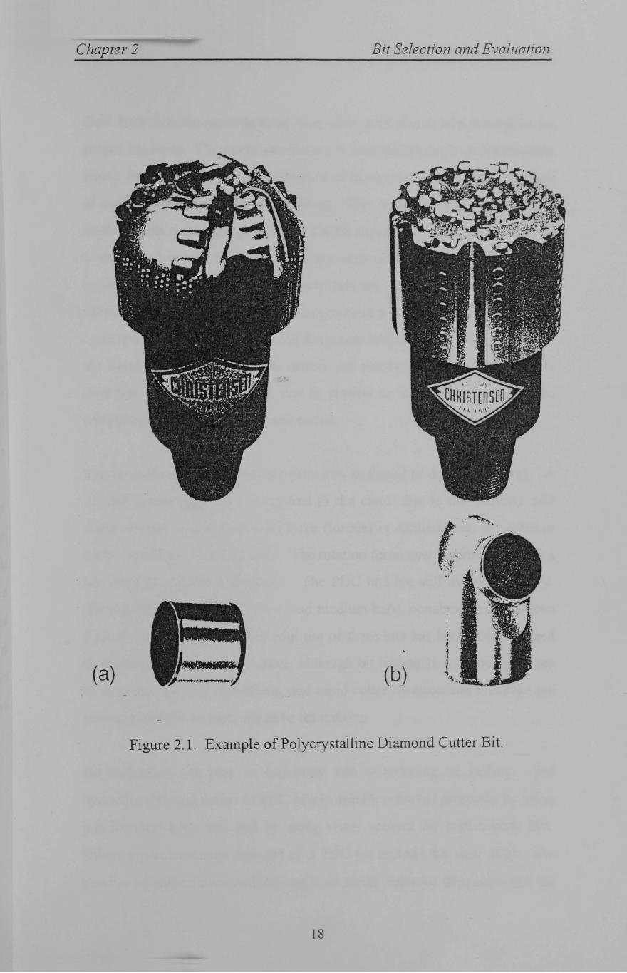
toughness of tungsten carbide. As shown in Figure 2.1, the sintered
polycrystalline diamond compact is bonded either to a tungsten carbide bit
body matrix or to a tungsten carbide stud that is mounted in a steel bit body.
Presently, cutters are available in a variety of sizes and shapes, depending
on the bit design and application.
The principal advantage of the matrix body bit construction is the ease with
which complex shapes can be obtained. Tungsten carbide is very erosion
and abrasion resistant, allowing the bit to have high fluid velocities across
the face. In addition, this material is better able to contend with drilling
fluids that contain high solids contents or hematite mud systems which are
very abrasive. An economic disadvantage does exist with tungsten carbide
bit bodies since the raw material is more expensive than the steel required
for steel body bits.
17
Chapter 2 Bit Selection and Evaluation
(a) (b)
Figure 2.1. Example of Polycrystalline Diamond Cutter Bit.
18
Chapter 2 Bit Selection and Evaluation
Steel body bits are manufactured from alloy steel that is heat treated to the
proper hardness. The cutter attachment is achieved through an interference
shrink fit process. A beneficial feature of these bits is the inherent strength
of cutter retention through press fitting. This process allows the bit to be
easily rebuilt since damaged cutters can be replaced. This has proven to be
a distinct advantage to operators in low cost drilling environments. Field
experience has shown that steel body bits are susceptible to erosion and
abrasion. This generally occurs in conjunction with high bit pressure drops,
extended bit runs, and/or high solids content drilling fluids. This becomes
the limiting factor when studs cutters can not be replaced or the nozzle
retention system is hampered, due to erosion or abrasion, thus losing the
rebuilding advantage as discussed earlier.
Polycrystalline diamond bits are primarily designed to drill by shearing. A
vertical penetration force is applied to the cutter due to the selected drill
collar weight, and a horizontal force (torque) is applied from the rotation
motor necessary to turn the bit. The rotation force may be provided from a
top drive or a down hole motor. The PDC bits are still evolving rapidly.
They perform best in soft, firm, and medium-hard, nonabrasive formations
that are not "gummy". Successful use of these bits has been accomplished
in sandstone, siltstone, and shale, although bit balling is a serious problem
in very soft, gummy formations, and rapid cutter abrasion and breakage are
serious problems in hard, abrasive formations.
Bit hydraulics can play an important role in reducing bit balling. The
hydraulic cleaning action of PDC bits is usually achieved primarily by using
jets for steel-body bits and by using water courses for matrix-body bits.
Other important design features of a PDC bit include the size, shape, and
number of cutters used and the angle of attack between the cutter and the
19
Chapter 2 Bit Selection and Evaluation
surface of the exposed formation. A self sharpening feature is inherent to
the diamond layer. As the diamond layer wears away new diamond is
exposed. This is due to the relative difference in abrasion resistance
between the diamond and the cobalt binder. The cobalt binder acts as
solvent/catalyst which promotes the intergrowth of the diamond crystals.
This feature is further enhanced by the lower abrasion resistance of tungsten
carbide, thus maintaining a positive angle between the cutter wear flat and
the formation. The cutter wear flat is defined as the flattened area of the
cutter which is caused by wear.
2.2.3 Rolling Cutter Bits
The roller or tri-cone bit is by far the most common bit type currently used
in rotary drilling operations. This bit type is available with a large variety
of tooth design and bearing types and, thus, is suited for a wide variety of
formation characteristics.
The drilling action of a rolling cutter bit depends to some extent on the
offset of the cones. Offsetting causes the cone to stop rotating periodically
as the bit is turned and the teeth scrape the hole bottom much like a drag bit.
This action tends to increase drilling speed in most formation types.
However, it also promotes faster tooth wear in abrasive formations. The
offset of the bit is a measure of how much the cones are moved so that their
axes do not intersect at a common point of the centreline of the hole. Cone
offset is sometimes expressed as the angle the cone axis would have to be
rotated to make it pass through the centreline of the hole. Cone offset angle
varies from about 4° for bits used in soft formations to zero for bits used in
extremely hard formations.
The shape of the bit teeth also has a large effect on the drilling action of a
roller cutter bit. Long, widely spaced, steel teeth are used for drilling soft
20
Chapter 2 Bit Selection and Evaluation
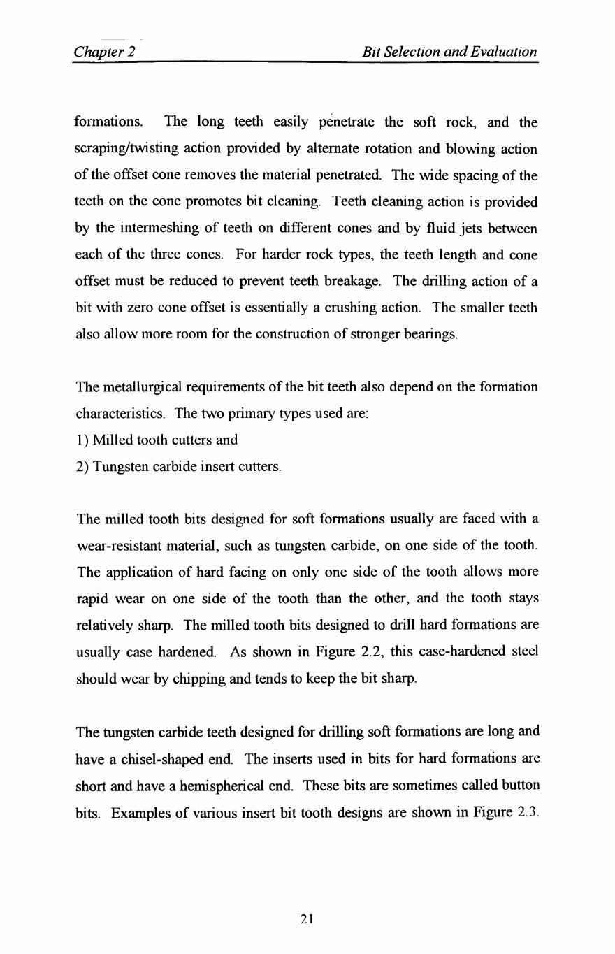
formations. The long teeth easily penetrate the soft rock, and the
scraping/twisting action provided by alternate rotation and blowing action
of the offset cone removes the material penetrated. The wide spacing of the
teeth on the cone promotes bit cleaning. Teeth cleaning action is provided
by the intermeshing of teeth on different cones and by fluid jets between
each of the three cones. F or harder rock types, the teeth length and cone
offset must be reduced to prevent teeth breakage. The drilling action of a
bit with zero cone offset is essentially a crushing action. The smaller teeth
also allow more room for the construction of stronger bearings.
The metallurgical requirements of the bit teeth also depend on the formation
characteristics. The two primary types used are:
1) Milled tooth cutters and
2) Tungsten carbide insert cutters.
The milled tooth bits designed for soft formations usually are faced with a
wear-resistant material, such as tungsten carbide, on one side of the tooth.
The application of hard facing on only one side of the tooth allows more
rapid wear on one side of the tooth than the other, and the tooth stays
relatively sharp. The milled tooth bits designed to drill hard formations are
usually case hardened. As shown in Figure 2.2, this case-hardened steel
should wear by chipping and tends to keep the bit sharp.
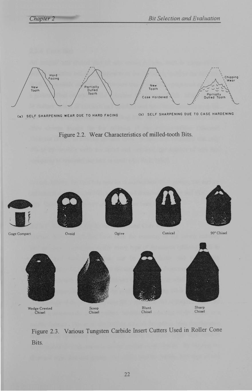
The tungsten carbide teeth designed for drilling soft formations are long and
have a chisel-shaped end. The inserts used in bits for hard formations are
short and have a hemispherical end. These bits are sometimes called button
bits. Examples of various insert bit tooth designs are shown in Figure 2.3.
21
pter 2
I I
I I
r--I •
Partially Dulled Tooth
(a) SELF SHARPENING WEAR DUE TO HARD FACING
Bit Selection and Evaluation
~
Case Hardened
, , I
I
I ,
" ChippinQ " Wear I
J V L. \ '...,-,-......,/,-,L \
"v........" ......., '- t......:
Partially Dull ed Tooth
(b) SELF SHARPENING DUE TO CASE HARDENING
Figure 2.2. Wear Characteristics of milled-tooth Bits.
Gage Compact
Wedge Cresled Chisel
Ovoid
Scoop Chisel
Ogive
/
Blunl Chisel
1\ . .~.~
Conical
Sharp Chisel
90° Chisel
Figure 2.3. Various Tungsten Carbide Insert Cutters Used in Roller Cone
Bits.
22
Chapter 2 Bit Selection and Evaluation
2.2.4 Core Bits
An integral and crucial part of any coring process, both in terms of the
overall operation and as a component of the drillstring itself, is the core bit.
With the possible exception of the core barrel, no other component can have
a greater effect on whether the operation will be successful. Many billions
of dollars worth of research and development have been invested over the
last forty years improving rotary drilling bits. However, core bits have seen
little change except for the addition of the Polycrystalline Diamond
Compact (PDC) to existing product lines. In fact, it is estimated that only
5% of the world's wells are cored and therefore, the number of core bits
compared to conventional bits, is small (Art Park, 1985).
In rock drilling, the core bits may be classified into three groups; the surface
set natural diamond core bits, impregnated diamond core bits and PDC core
bits. Core bits using rotary cones have also been developed.
2.2.4.1 The Surface Set Natural Diamond Core Bit
Natural diamond core bits have been the mainstay of the coring industry
and are used to core practically every type of formation (although soft to
medium-hard formations often can be cored faster and better with
impregnated or PDC bits). With the introduction of these new bits, natural
diamonds should probably be reserved for coring those relatively hard and
abrasive formations that cannot be cored easily by any other method. The
manufacture of the surface set core bit is similar to the impregnated core bit
in that it involves the use of carbon moulds and sintering of the matrix in a
muffle furnace. However, the surface set core bit differs from impregnated
diamond bit by having the diamonds, which are much larger than used in
impregnated core bit, set only on the surface of the crown. By varying the
diamond type, size and quality, the matrix and the profile, this type of bits
23
Chapter 2 Bit Selection and Evaluation
will drill and core satisfactorily in' all solid and homogeneous formations
and can be made to suit any core barrel. It does not perform well in broken
or loose zones, if this problem is expected, then Carbonado diamonds are
recommended. The selection of the correct size, grade, type of diamond is a
major factor influencing the cost per foot/metre of diamond bits. The size,
quality, quantity and exposure of the diamonds used in a surface set core bit
are dependent on the rock type drilled. Soft formation core bit use larger
diamonds in the size 12 to 20 stones per carat, which can be of a lower
quality and fewer in quantity. However, hard formations core bits use
smaller diamonds in the size range 50 to 90 stone per carat, which are of a
higher quality and greater in quantity.
In this type of core bit, the diamonds are placed in the matrix at a depth
which leaves about one eight to one third of them exposed. Smaller
diamond exposure is used in hard fractured and abrasive formations,
whereas greater diamond exposure is used in soft and medium rocks. The
matrix of surface set core bit is highly resistant to wear and abrasion,
whether from the bit rotating against the formation or from the high velocity
mud flowing through the water courses moulded into it, whereas matrix
wear is an important feature of the impregnated core bit. The matrix
material is of paramount importance, since it holds the bit together as well
as securing the diamonds in place while they drill. Standard matrix is used
for low abrasive formations, and extra hard matrix is used for high abrasive
rocks. The selection of matrix hardness is very important for the core
recovery.
The semi round profile is the most commonly used crown shape for thin
walled core bits. It requires a low bit load and a lower diamond content,
because the profile has the smallest crown surface area. A stepped profile
24
Chapter 2 Bit Selection and Evaluation
is used in manufacture of thick walled core bits. This profile gives good
penetration and straight hole, especially in harder formations when using
higher bit loads.
In order to distribute a flushing medium over the core bit face, it is essential
requirement for a core bit to have flush channels. There are three types of
channels in the surface set bits; the full face discharge, the internal, and the
spiral type. The full face discharge type of flush channels comprises of a
series of holes through the core bit front and the matrix which direct the
flushing medium directly onto the cutting face. The flush channels can be
oval, rectangular or round in shape and are designed to limit contact of the
flushing medium with the core sample. This prevents erosion and washing
away of the core, when soft formations are drilled. The number and size of
face discharge flush channels are dependent on the core bit size and type of
formations to be drilled. The face discharge flush channels are mainly used
for thicker walled core bits.
The internal discharge type of the flush channels consists of a slot passing
directly across the core bit front from the inner to outer wall of the crown.
The number of flush channels increases when the core bit size increases,
because the matrix segments are usually kept at a uniform length. When
soft formation is drilled, a greater flush flow rate will be required.
The third type of the flush channels, known as the spiral type, consists of
spirally radiating flush channels over the core bit face from the inner
surface to outer surface of the core bit. This type of channel is especially
suitable for core bits containing medium to large sized diamonds which
produce large amounts of cuttings.
25
Chapter 2 Bit Selection and Evaluation
2.2.4.2 Impregnated Diamond Core Bits
The concept of impregnated core bits has been around for approximately
five decades. The early impregnated core bits were only used on a limited
scale and utilised predominantly crushed and lower grade natural diamonds.
This restricted their application as the surface set core bits could be
manufactured with superior performance characteristics. However, with the
wider availability and increased quality of synthetic diamonds manufactured
to various levels of impact resistance, core bit manufacturers were able to
develop the impregnated core bit concept to maximise the benefits of
synthetic diamonds. This led to impregnated core bits becoming fully
accepted within the drilling industry. The major reasons for this acceptance
are the recent developments which have resulted in many cases, having
superior performance characteristics and lower costs than surface set core
bits. This is particularly so in the sector of the market previously occupied
by surface set core bits (Cumming, 1956).
The benefit of greater core bit life for impregnated core bit is particularly
advantageous when wireline coring and coring at greater depth, as it greatly
reduces the time wasted and the risk of a borehole caving when round
tripping to replace worn out core bits. Although a new surface set core bit
often have a greater penetration rate than a comparable impregnated core
bit, a uniform penetration rate offers and allows for easier coring operations
by an impregnated core bit. Other factors which have contributed to the
recent wide use of impregnated core bit are their durability against rough
handling and their suitability for coring in fractured formations. Also they
are more suitable for use at high rotational speeds and lower bit loads,
which allows lighter weight drilling rigs and equipment to be used, and
reduces the tendency for borehole deviation.
26
Chapter 2 Bit Selection and Evaluation
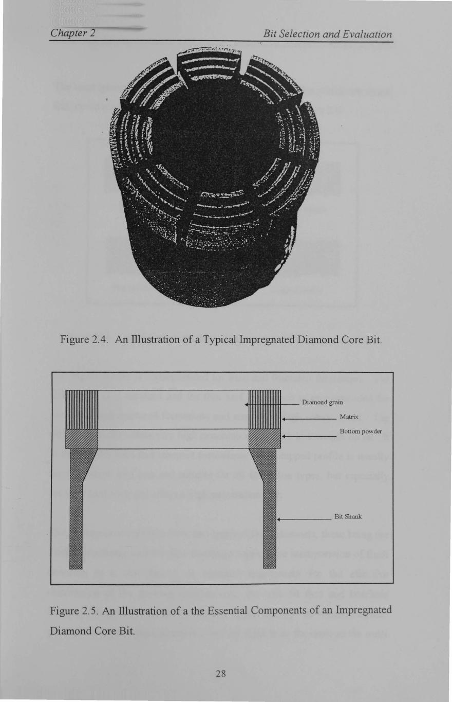
Impregnated core bits are now the predominant type used by the core
drilling industry and have been used in the field work presented in this
thesis. Figure 2.4 shows a typical diamond impregnated core bit, and
Figure 2.5 illustrates the essential components of which it is comprised.
The manufacture of a diamond impregnated core bit starts with the
construction of the crown. The crown material is a powder mixture of
cobalt, tungsten carbide, copper, nickel, aluminium, molybdenum and iron
which can be tailored to control wear resistance of the matrix. If required,
further matrix powder and diamond grain can be added and the process
repeated to build up the desired crown thickness, or depth of impregnation.
A backing powder, which contains no diamonds, is then placed on top of
the compressed matrix powder and diamond grain, to provide a firm fix for
the cutting crown to the core bit blank. The core bit blank is pressed into
the mould and the whole assembly is placed in a controlled temperature and
environment of muffle furnace, where sintering of the matrix takes place.
The diamonds used in an impregnated core bit are very much smaller than
those used in a surface set core bit and are typically in the size range 80-
1000 stone per carat. The concentration of the diamonds, i. e. actual size,
quality and quantity, used in an impregnated core bit depends on the rock
properties it is designed to drill and the drilling equipment limitations.
However, the general rule for diamond selection is that the harder the rock,
the finer sizes, lower quantity and higher quality diamonds are used.
Nearly all diamonds used are synthetic in origin and therefore have good
properties for drilling. A range of grades is available for different
applications (Atkins, 1983).
27
Chapter 2 Bit Selection and Evaluation
Figure 2.4. An illustration of a Typical Impregnated Diamond Core Bit.
~tmt+tifttt+tH-- Diamond grain
...... ____ Matrix
Bonom powder .... ~----
+--____ Bit Shank
Figure 2.5. An illustration of a the Essential Components of an Impregnated
Diamond Core Bit.
28
Chapter 2 Bit Selection and Evaluation
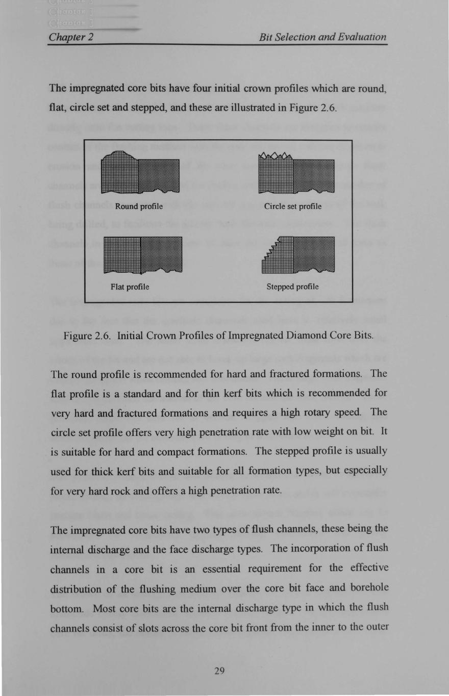
The impregnated core bits have four initial crown profiles which are round,
flat, circle set and stepped, and these are illustrated in Figure 2.6.
Round profile Circle set profile
Flat profile Stepped profile
Figure 2.6. Initial Crown Profiles of Impregnated Diamond Core Bits.
The round profile is recommended for hard and fractured formations. The
flat profile is a standard and for thin kerf bits which is recommended for
very hard and fractured formations and requires a high rotary speed. The
circle set profile offers very high penetration rate with low weight on bit. It
is suitable for hard and compact formations. The stepped profile is usually
used for thick kerf bits and suitable for all formation types, but especially
for very hard rock and offers a high penetration rate.
The impregnated core bits have two types of flush channels, these being the
internal discharge and the face discharge types. The incorporation of flush
channels in a core bit is an essential requirement for the effective
distribution of the flushing medium over the core bit face and borehole
bottom. Most core bits are the internal discharge type in which the flush
channels consist of slots across the core bit front from the inner to the outer
29
Chapter 2 Bit Selection and Evaluation
wall of the core bit. Face discharge flush channels consist of a series of
holes through the core bit front and matrix, which pass the flush medium
directly onto the cutting face. These flush channels are designed to restrict
contact of the flushing medium with the core and hence, reduces or prevents
erosion and washing away of the core sample. Face discharge flush
channels are primarily intended for thicker walled core bits. The number of
flush channels increases with the core bit size and the softness of the rock
being drilled, to facilitate the greater flush flowrate requirement. The flush
channels in the impregnated core bit have the same function and form as
those of the surface set core bit.
The impregnated core bits are unsuitable for the coring of soft formations
due to the fact that the synthetic diamonds used have a relatively small
upper size limit. The small sized diamonds restrict flush flow over the
crown of the bit and are not able to break up large rock fragments which are
usually produced when drilling soft formations. These large rock fragments
tend to roll between the bottom of the core bit and the rock surface. These
problems cause the core bit to become clogged and cease cutting and
therefore make the bit unsuitable for coring in soft formations.
Due to the inevitable shocks and heating to which a diamond is subjected
when drilling, its cutting edge will slowly wear away and it will eventually
become blunt and cease cutting. This slow natural blunting action can be
accelerated by improperly applied drilling parameters and poorly
maintained equipment.
The crown of an impregnated core bit consists of a large number of small
diamonds evenly distributed within a sintered matrix. As an impregnated
core bit drills, the matrix is subjected to abrasion and slowly wears away.
30
Chapter 2 Bit Selection and Evaluation
The rate at which it. wears is ideally the same as the rate at which the
diamonds wear and therefore as the diamonds become blunted and cease to
cut effectively, they are released from the matrix and new sharp diamonds
are exposed to take over their cutting role. This action gives the
impregnated core bit a self sharpening characteristic which allows the bit to
be used until the whole of the crown is consumed. As impregnated core
bits are manufactured in a whole range of matrix harnesses, the selection of
the proper hardness is important to ensure the bit wears away at the correct
rate and retains its cutting efficiency. However, the general guide lines for
the selection of matrix hardness are; the harder the formation, the softer the
matrix, and the more "troublesome" the conditions, i.e. powerful machine,
vibration, abrasive or broken formations, the harder the matrix, (Atkins,
1983).
2.2.4.3 Polycrystalline Diamond Compact (PDC) Core Bits
Although PDC has existed for more than 40 years, real advances in drilling
efficiency were achieved in the early 1980s. A growing understanding of
PDC thermal wear rate response, rock cutting, mechanics, and design
features that affect bit performance has contributed to the rapid evolution of
PDC bits. The PDC bit is a new generation of the old drag or fishtail bit
and does not have moving parts such as bearings PDC was originally
developed for cutting tools in machining applications and is considered to
provide high abrasion resistance essential to long life in a drag type bit
(Madigan and Caldwell, 1981). New, more hydraulically and mechanically
efficient bit designs and optimisation of operating parameters have
increased the PDC application to include shallow and intermediate holes in
mine extraction and mineral and oil explorations.
31
ehclpter 2 Bit Selection and Evaluation
The introduction of PDC cutters for rock drilling available in large pieces
(up to 50 mm in diameter) and therefore, rock cutting elements for a PDC
bit can be cut from these large discs in shapes which have optimum
geometry for use in core bits (Clark and Shafto, 1987). Coring bits with
PDC cutters are designed to drill rock primarily by a shearing action which
requires less energy than by crushing. This means that less bit load can be
used for drilling which results in less wear and tear on the drilling rig and
drill string.
The manufacture of polycrystalline diamond bits consists of three main
components, and namely are man-made diamond crystals, tungsten carbide
matrix and steel alloy. The use of these three materials is based on their
characteristics such as machinability, strength, ductility, thermal
conductivity, erosion/abrasion and thermal shock resistance. The man
made diamond crystals are bonded to a cemented tungsten carbide substrate
or brazed onto a bit head in a high temperature and high pressure process
depending on whether the bit is a matrix or a steel body respectively. The
matrix body bits are manufactured utilising a tungsten carbide powder
bonded together with a binder metal composed of a nickel-copper alloy.
The matrix crown profile, steel bit blank and the shank are the main
components in the manufacturing of the bit body.
2.3 Bit Selection and Evaluation
The drill bit's performance determines much of the drilling costs, and
performance, in turn, depends on the bits selected and how they are run.
Unfortunately, the selection of the best available bit for the job, like the
selection of the best drilling fluid or casing cement composition, can be
determined only by trial and error. The following methods can be used to
32
Chapter 2 Bit Selection and Evaluation
select the most appropriate bit type for a particular formation:(a) well bit
records and geological information; (b) specific energy; ( c) bit dullness; and
(d) the most valid criterion for comparing the performance of various bits is
the cost per unit interval drilled. Since no amount of arithmetic allows us to
drill the same section of the hole more than once, com pari sons must be
made between succeeding bits in a given well or between bits used to drill
the same formations in different wells. The formations drilled with a given
bit on a previous nearby well can be correlated to the well in progress using
well logs and mud logging records.
The initial selection of bit type in a wildcat area can be made on the basis of
what is known about the formation characteristics and drilling cost in an
area. The terms usually used by drilling engineers to describe the formation
characteristics are drillability and abrasiveness. The drillability of the
formation is a measure of how easy the formation is to drill. It is inversely
related to the compressive strength of the rock, although other factors are
also important. Drillability generally tends to decrease with depth in a
given area. The abrasiveness of the formation is a measure of how rapidly
the teeth of a milled tooth bit will wear when drilling the formation.
Although there are some exceptions, the abrasiveness tends to increase as
the drillability decreases.
In the absence of prior bit records, general rules are often used for initial bit
selection, but the drilling cost per foot must eventually be the final criterion
applied. However, the rules indicate certain tendencies shown to be
common on the basis of past experience. Some of these rules, used by
many drilling engineers are as follows;
33
Chapter 2 Bit Selection and Evaluation
1) The International Association of Drilling Contractors (lAD C)
classification charts provide an approximate listing of the bit type
applicable in a given formation hardness.
2) The initial bit and features selected should be governed by bit cost
considerations. Premium rolling-cutter design features and high-cost
diamond and PDC drag bits tend to be more applicable when the daily
cost of the drilling operation is high. The cost of the bit probably should
not exceed the rig cost per day.
3) Three-cone rolling-cutter bits are the most versatile bit type available and
are a good initial choice for the shallow portion of the well.
4) Diamond drag bits perform best in nonbrittle formations having a plastic
form of failure, especially in the bottom portion of a deep well, where the
high cost of tripping operations favours a long bit life, and a small hole
size favours the simplicity of a drag bit design.
5) PDC drag bits perform best in uniform sections of carbonates or
evaporates that are not broken up with hard shale stringers or other brittle
rock types.
6) PDC drag bits should not be used in formations, which have a strong
tendency to stick to the bit cutters.
7) When using a rolling-cutter bit:
a) The bit with the longest tooth size possible should be used.
b) A small amount of tooth breakage should be tolerated rather than
selecting a shorter tooth size.
c) When enough weight cannot be applied economically to a milled tooth
bit to cause self sharpening tooth wear, a longer tooth size should be
used.
d) When the rate of tooth wear is much less than the rate of bearing wear,
a longer tooth size or a better bearing design should be selected, or
more bit weight should be applied.
34
Chapter 2 Bit Selection and Evaluation
e) When the rate of bearing wear is much less than the rate of tooth wear,
a shorter tooth size or more economical design should be selected or
less bit weight should be applied.
2.3.1 Cost Per Interval Drilled
Often data are available for bit performances in offset wells in the same or
in similar formations. Experienced rig personnel and bit suppliers can
interpret the offset bit records, correcting for mud differences, depth
changes and variations in bit hydraulics practices. Then the expected
performance of the candidate bit selection could be reasonably forecasted.
The expected performance and net cost of each candidate bit would then be
used to calculate its expected average drilling cost per foot. The candidate
drill bit with the lowest drilling cost per foot under normal circumstances is
the bit selected to run. These comparisons of bit records and drilling cost
calculations are carried out beforehand, so to ensure that the chosen drill bit
is available at the rig site before the preceding bit is tripped out of the hole.
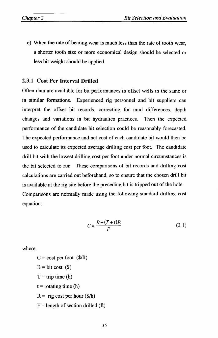
Comparisons are normally made using the following standard drilling cost
equation:
where,
B+(r +t)R c=---'----F
C = cost per foot ($/ft)
B = bit cost ($)
T = trip time (h)
t = rotating time (h)
R = rig cost per hour ($/h)
F = length of section drilled (ft)
35
(3.1)
Chapter 2 Bit Selection and Evaluation
The above equation shows that cost per interval drilled (foot) is controlled
by five variables. For a given bit cost, B, and hole section, F, cost per foot
will be highly sensitive to changes in rig cost per hour, R, trip time, T and
rotating time, t. The trip time may not always be easy to determine unless a
straight running in and pulling out of hole is made. If the bit is pulled out
for some reason, say a wiper trip, then such duration if added, will influence
the total trip time and, in tum, cost per foot. Bit performance, therefore,
would be changed by arbitrary factor. Rotating time is straightforward and
is directly proportional to cost per foot, assuming that other variables
remain constant.
The cost per foot is greatly influenced by the cost of the rig. For a given
hole section in a field that is drilled by different rigs, having different values
of rig costs, the same bit will produce different values of cost per foot,
assuming that the rotating time is the same. In this case, if the value of rig
cost is taken as arbitrary, then the above equation would yield equivalent
values of cost per foot, which is not a real value and does not relate to
actual or planned expenditure.
In different parts of a given hole section, performance of a bit could be
determined from the cumulative cost per foot (CCF). In this method, a cost
per foot for short intervals is determined by the above equation and
assuming a reasonable figure for round-trip time. When the CCF value
starts increasing, (Moore, 1974) suggests that it is time to pull the bit out of
the hole. In other words, the CCF would be used as a criterion for
determining the depth at which the current bit becomes uneconomical.
(Rabia, 1985), points out, that the drawbacks with the use of the CCF
method are; (a) accurate measurement and prediction of footage, trip and
rotating times are necessary; and (b) the CCF may suddenly increase as a
36
Chapter 2 Bit Selection and Evaluation
result of drilling a hard streak of formation and may decrease once the bit
passed this streak. These uncertainties on the evidence of one CCF value
may result in pulling out of a bit prematurely. Therefore, a simpler and
more practical method, is required, whereby the performance of a bit can
be quantified in each formation type of the section it drills. This method is
capable of being correlated with cost per foot to simplify the analysis of
well cost and is known as the Specific Energy.
2.3.2 Drilling Specific Energy
The specific energy method provides a simple and practical method for the
selection of drill bits. Specific energy, SE, may be defined as the energy
required to remove a unit volume of rock and may have any set of
consistent units. The drilling specific energy equation has been derived by
considering the mechanical energy expanded at the bit. (Moore, 1974), has
shown that the specific energy for rotary drilling may be calculated from the
following equation:
20WN SE= t
DF
Where,
SE = Drilling specific energy (MJ/m3)
W = Weight on bit (kg)
N = Rotating speed (rpm)
D = The hole diameter (mm)
F = Footage (ft)
t = Rotating time (min)
(3.2)
Several researchers (Teale, 1965, Paone et al., 1969, Schmidt, 1972, Mellor.
1972, Tandanand and Unger, 1975, Rabia, 1980, Barr and Brown, 1983,
37
Chapter 2 Bit Selection and Evaluation
Miller and Ball, 1990, Rowsell and Waller, 1991) have shown that drilling
specific energy is dependent on the design and geometry of the drill bit,
drill type, methods of cuttings removal, depth of drill hole, weight on bit,
rotational speed, rate of penetration and the rock strength. It was concluded
by (Rabia, 1982) that the specific energy is not a fundamental intrinsic
property of rock. This means that, for a formation of a given rock strength,
a soft formation bit will produce an entirely different value of specific
energy from that produced by a hard formation bit. This property of
specific energy, therefore, affords accurate means for selection of
appropriate bit type. The bit that gives the lowest value of specific energy
in a given section is the most economical bit.
The above mentioned authors observations conclude that, because the
specific energy is considered as the amount of energy required to penetrate
rock, then it is a very significant measure of drilling efficiency and an
indicator of bit condition. Also, it follows that specific energy is a direct
measure of bit performance in a particular formation and provides an
indication of the interaction between bit and rock. The fact that specific
energy, when compared with the penetration rate, is less sensitive to
changes in weight and rotary speed makes it a practical tool for bit
selection.
2.3.3 Bit Dullness
The dull bit condition indicates the difficulty the tool faced on bottom. A
critical evaluation of the pulled bit provides vital clues for selection of a bit
for the next run. The degree of dullness can be used as a guide for selecting
a particular bit. Bits that wear too quickly are obviously less efficient and
have to be pulled out of the hole more frequently, which increase total
drilling cost. Dull bit grading can also indicate the weak areas of the tool or
38
Chapter 2 Bit Selection and Evaluation
even poor operating practices. Improving these weak links and analysing
rock strength can aid in picking the best possible bit for the next run.
Dull bit grading is considered an art, and expertise is gained through
experience. A good understanding of how to grade and analyse dull bits
can lead to better bit selection and use, eventually cutting overall drilling
costs. Many bit manufacturers and drilling companies have described new
systems of reporting dull bit conditions, but most people working at the drill
sites find it difficult to identify the exact pattern of bit wear. The most
commonly used scheme for dull bit was developed by the IADC. This
checklist also indicates the remedial measures to prevent recurring
problems. Once a bit dulling characteristic has been identified, steps can be
taken to incorporate the suggested improvements in bit selection and its
operation.
2.3.3.1 Grading Tooth Wear
The tooth wear is graded in terms of the fractional tooth height that has
been worn away and is given a code from T-l to T-8. T-l indicates that one
eighth of the tooth height has gone; T4 indicates that half of the tooth has
been worn away, i.e., the teeth are 4/8 worn. Unfortunately, some teeth of a
bit may be worn more than others and some may be broken, which make it
difficult to characterise the tooth wear of the entire bit with a single
number. Generally, the broken teeth are indicated by recording "B T" in a
"remarks" column and the average wear of the teeth with the most severe
wear is reported. Taking measurement of tooth height before and after the
bit run, is considered the best way of obtaining tooth wear. However, with
experience, more rapid visual estimates of tooth condition can be made
using a profile chart guide see Figure 2.7.
39
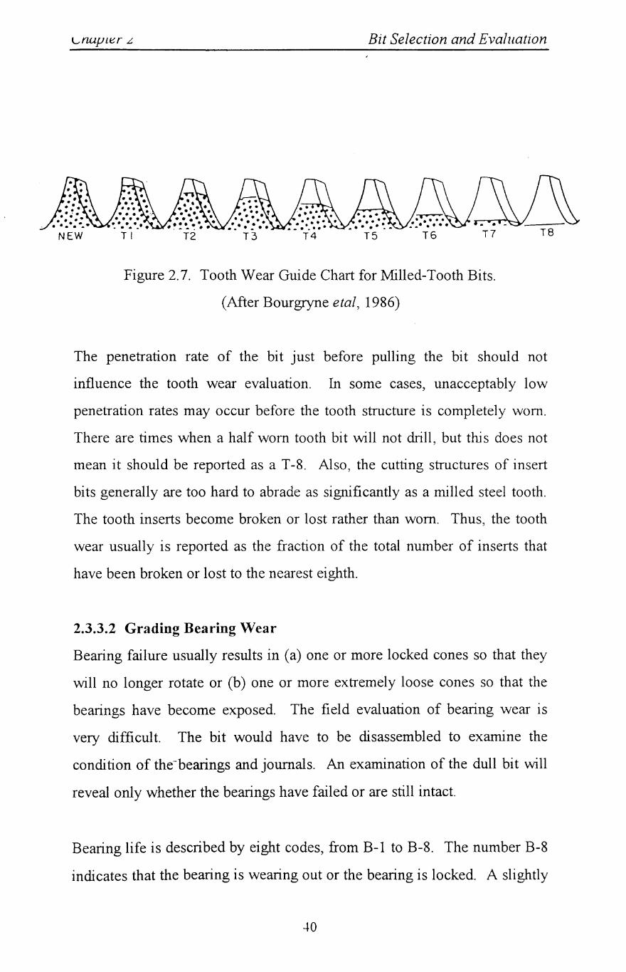
l."napler L Bit Selection and Evaluation
NEW TI T2 T3 T4 T5 T6 T7
Figure 2.7. Tooth Wear Guide Chart for Milled-Tooth Bits.
(After Bourgryne etal, 1986)
The penetration rate of the bit just before pulling the bit should not
influence the tooth wear evaluation. In some cases, unacceptably low
penetration rates may occur before the tooth structure is completely worn.
There are times when a half worn tooth bit will not drill, but this does not
mean it should be reported as a T -8. Also, the cutting structures of insert
bits generally are too hard to abrade as significantly as a milled steel tooth.
The tooth inserts become broken or lost rather than worn. Thus, the tooth
wear usually is reported as the fraction of the total number of inserts that
have been broken or lost to the nearest eighth.
2.3.3.2 Grading Bearing Wear
Bearing failure usually results in (a) one or more locked cones so that they
will no longer rotate or (b) one or more extremely loose cones so that the
bearings have become exposed. The field evaluation of bearing wear is
very difficult. The bit would have to be disassembled to examine the
condition of the-bearings and journals. An examination of the dull bit will
reveal only whether the bearings have failed or are still intact.
Bearing life is described by eight codes, from B-1 to B-8. The number B-8
indicates that the bearing is wearing out or the bearing is locked. A slightly
.+0
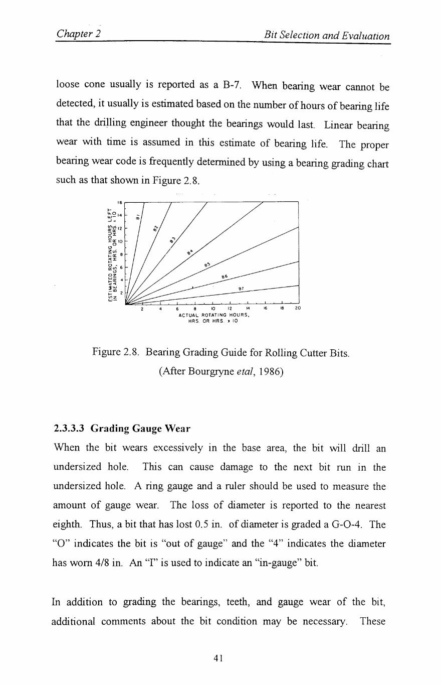
Chapter 2 Bit Selection and Evaluation
loose cone usually is reported as a B-7. When bearing wear cannot be
detected, it usually is estimated based on the number of hours of bearing life
that the drilling engineer thought the bearings would last. Linear bearing
wear with time is assumed in this estimate of bearing life. The proper
bearing wear code is frequently determined by using a bearing grading chart
such as that shown in Figure 2.8.
2 4 6 8 10 12 14 16 18 20
ACTUAL ROTATING HOURS. HRS. OR HRS. l 10
Figure 2.8. Bearing Grading Guide for Rolling Cutter Bits.
(After Bourgryne etal, 1986)
2.3.3.3 Grading Gauge Wear
When the bit wears excessively In the base area, the bit will drill an
undersized hole. This can cause damage to the next bit run in the
undersized hole. A ring gauge and a ruler should be used to measure the
amount of gauge wear. The loss of diameter is reported to the nearest
eighth. Thus, a bit that has lost 0.5 in. of diameter is graded a G-0-4. The
"0" indicates the bit is "out of gauge" and the "4" indicates the diameter
has worn 4/8 in. An "I" is used to indicate an "in-gauge" bit.
In addition to grading the bearings, teeth, and gauge wear of the bit,
additional comments about the bit condition may be necessary. These
41
Chapter 2 Bit Selection and Evaluation
remarks about the bit condition should enable those who subsequently will
use the bit records to visualise readily the actual condition of the bit.
2.3.4 Variable Information Analysis
The bit selection is not an exact science, and the aim of any bit selection
tool is to reduce the trial and error to the minimum amount. The analysis of
variable information is considered only as a guide to force the thought
process and offers a mental picture of the design requirements of the bit.
The variable information sources includes:
• Offset well bit record analysis
• Offset well log analysis
• IADe bit coding
• Manufacturers' product guides
• Geophysical data analysis
• General geological considerations
Offset well logs and bit records are the most important source of
information. Wireline well logs can provide a continuous recording of
formation parameters versus depth which are very useful for correlation
studies. Well to well correlations can give the following insight to the
proposed well;
• The types of formations present.
• The elevation of formations in the well relative to others.
• Whether the well is within a given geological structure.
• Whether sufficient formation intervals exist to be economically drilled
by a diamond bit.
42
Chapter 2 Bit Selection and Evaluation
• Approximate depths at which a bit may need to be pulled.
• The presence of faults.
Mud logs from offset wells can provide a wealth of information regarding
the lithology of an upcoming well. Perhaps the greatest benefit is the
geological analysis of cuttings to produce a geocolumn. This display serves
as an excellent indicator of what will be drilled. In addition, the penetration
rate log can be of use in determining the drillability of the proposed
formation interval. Infereces to formation properties can be made, affecting
the final bit selection and proposed operational parameters. With all this
information correlated to depth, an assessment can be made of which
formation intervals in the proposed well are diamond bit applicable.
If the previously mentioned data is unavailable, an offset bit record should
be consulted. Otherwise, the risk of poor performance will be greatly
increased. When selecting a bit, it naturally follows that an estimation of
potential footage, penetration rate, and cost savings should be given. The
following guidelines are recommended for selecting bit records;
1) The most recent bit record will normally be the best indicator of the type
of performance to be expected in a proposed drilling interval.
2) Probability is highest when the drilling technology used is most similar to
what will be available.
3) The nearest offset records Increase the chance that the formations
encountered in the proposed well will be the same and exhibit similar
drill ability. In faulted areas, an attempt should be made to verify that the
offset data is on the same side of the fault as the proposed well. If not, a
comparison of bit runs in the same formations is recommended, although
they may be at di fferent true vertical depths.
43
Clwpter 2 Bit Selection and Evaluation
4) Bit sizes and casing programmes should be similar. Different bit sizes
affects the ultimate penetration rate, even when all other variables are
equal. Cost comparisons can also be affected.
5) Comprehensive dull grades should be available. They will provide a
qualitative gauge of the formation abrasiveness. Furthermore, they can
give insight to the required type and density of cutters needed to drill.
6) Similar mud type and mud weights are also important, in that different
bits will perform differently depending on mud types and properties. An
example of this is that PDC bits perform significantly better in oil based
mud.
7) Finally, the total depth should be at least equal to or greater than the
proposed well. If formation tops change radically, then a conformation
should be made that the offset bits drilled the same formation to be
drilled.
Methods have been proposed for selecting rock bits using offset well logs
such as sonic and gamma-ray logs (Somerton and El-hadidi, 1970, Mason,
1984). These methods appear to work but involves substantial time in the
analysis of the logs and in the interpretation of the results.
The international association of drilling contractors IADe bit code offers a
method of bit selection based on bit type. If approximate formation
properties are known, the table can be used to choose the appropriate bit
type. Its drawback is that the geological description contained in the table,
on which the bit type is selected, is rather limited. Even if this description
was improved, the available geological knowledge from a prospective field
would probably be inadequate for use with such a table to select bits.
44
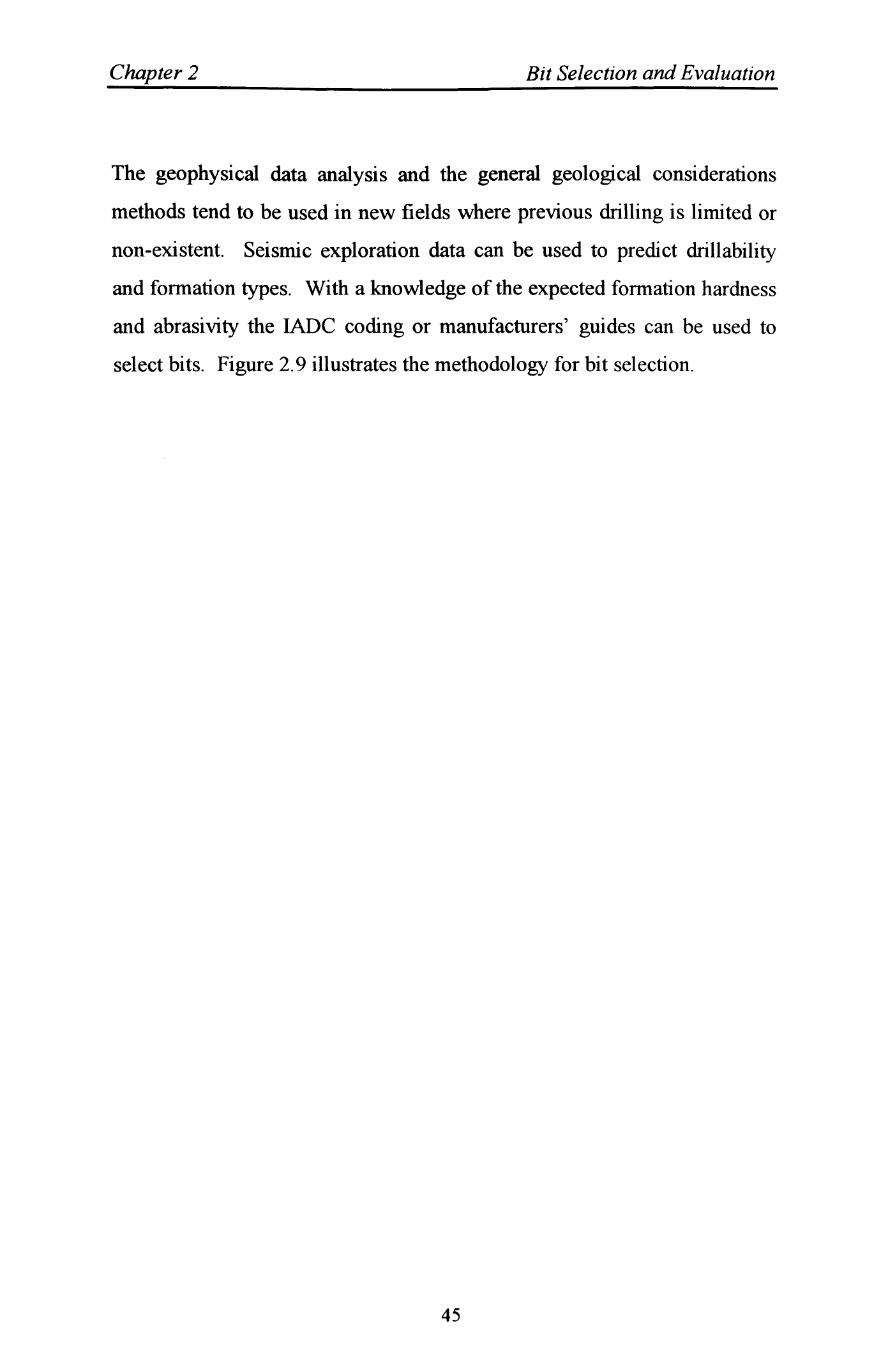
Chapter 2 Bit Selection and Evaluation
The geophysical data analysis and the general geological considerations
methods tend to be used in new fields where previous drilling is limited or
non-existent. Seismic exploration data can be used to predict drillability
and formation types. With a knowledge of the expected formation hardness
and abrasivity the lADe coding or manufacturers' guides can be used to
select bits. Figure 2.9 illustrates the methodology for bit selection.
45
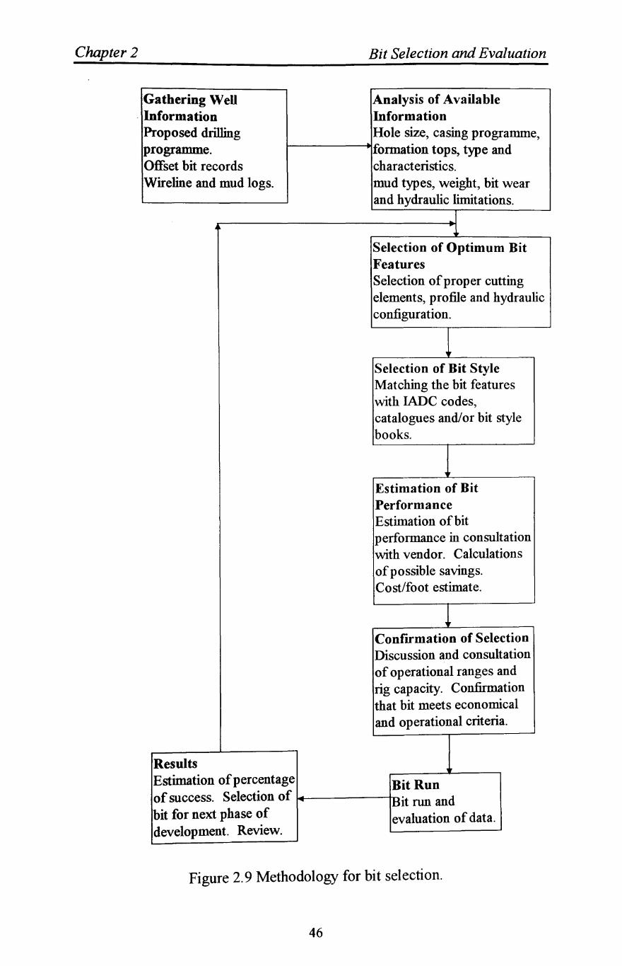
Chapter 2
Gathering Well Information Proposed drilling programme. Offset bit records Wireline and mud logs.
Results
Bit Selection and Evaluation
Analysis of Available Information Hole size, casing programme,
I-------+lformation tops, type and characteristics. mud types, weight, bit wear and hydraulic limitations.
Selection of Optimum Bit Features Selection of proper cutting elements, profile and hydraulic configuration.
Selection of Bit Style Matching the bit features with IADC codes, catalogues and/or bit style books.
Estimation of Bit Performance Estimation of bit performance in consultation with vendor. Calculations of possible savings. Cost/foot estimate.
ConfIrmation of Selection Discussion and consultation of operational ranges and rig capacity. Confirmation that bit meets economical and operational criteria.
Estimation of percentage Bit Run of success. Selection of ~~-------iI-nH:it run and bit for next phase of evaluation of data. development. Review.
Figure 2.9 Methodology for bit selection.
46
Chapter Three
SLIM HOLE CONTINUOUS CORE DRaLING
3.1 Introduction
For many years, exploration world-wide has yielded disappointing results
for the oil and gas industry as a whole. It has primarily evolved as a costly,
time-consuming practice where each well is planned as a major discovery
(Strong, 1989). Additionally, the information obtained during drilling is of
minimal quality and detail to significantly impact the evaluation of the total
exploration/exploitation play.
Recognising the need for a revolutionary change in exploration strategy,
many companies decided to explore a new approach based on optimising
initial seismic acquisition and using a high speed, automated, slim hole
continuous core drilling system.
The high speed drilling system was a logical approach for many companies
which hasresulted in several years of research effort. The adaptation to slim
hole drilling posed several new technical changes, which are discussed
herein.
3.2 The Evolution of Continuous Coring Slim Hole System
A slim hole well is defined in the drilling industry as a well where 90% or
more of the length of the well is drilled with bits less than 7 in. (17.8 cm) in
diameter, (Walker and Millheim, 1989). Slim hole drilling is not new, as
both the explorationist and the exploitationist has recognised the possibility
47
Chapter 3 Slim Hole Continuous Core Drilling
of using a small diameter well bore to help reducing the overall drilling
costs. In the fifties a major operator launched an initiative to drill slim hole
exploitation wells in Arkansas and Oklahoma, and stated in the conclusions
that slim hole wells could be cost effective, (Flatt, 1954). Slim hole drilling
was developed in Sweden to explore and exploit the shallow reservoirs in
the country, (Dah, 1982) again cited a 75% cost savings in this approach
over conventional drilling practices. The success in Sweden encouraged
explorationist and exploitationist to utilise more slim hole drilling in
Europe, (Floyd, 1987), then in remote areas such as Indonesia, where the
smallness of the overall drilling system and the reduction in wellbore size
greatly impacted the logistical cost for drilling these wells, (Macfadyen and
Boyington, 1986).
The greatest use of slim hole technology is for continuous coring by the
mining industry. This technology has been considered as the only sure way
to evaluate whether an ore body is large and has a sufficient mineral grade
to justify the cost of sinking shafts or embarking on a costly open cut is to
obtain data to delineate the ore body. With the apparent interest in slim
hole and continuous core drilling over the last 40 years, both approaches
has not gained acceptance by the oil and gas exploration and exploitation
sectors. Due to this very pertinent concern, some key issues deserve to be
exposed and briefly discussed. This chapter addresses these issues with the
sole purpose of examining the possibilities of slim hole and continuous-core
drilling in the oil and gas industry.
48
Chapter 3 Slim Hole Continuous Core Drilling
3.3 Reasons for Slim Hole Continuous Core Drilling
There are two basic reasons to consider drilling a slim hole. The first is
very simple and basic; better economics. The second is related to the
continuous core mining drilling industry. To achieve a high percentage core
recovery and to be cost effective, it is preferable to drill a slim hole.
The argument against drilling a conventional slim hole well is production
limitations imposed by the small diameter pipe and the difficulties in work
over for such wells. The other often cited reasons, are the lack of good
penetration rates using small diameter tri-cone bits, the deficiency of
logging tools that would fit into the slim hole and difficulty to test,
cementing the small hole and the inability to run multiple casing strings.
Together with these complaints, an additional concern is the safety of
drilling with a small annulus system when using continuous core drilling.
The current exploration paradigm of all companies exploring for oil and
gas, is to spend a significant portion of an exploration budget on costly
seiSmIC programmes. (Ashton, 1984) presents the current exploration
practised by most oil and gas exploration companies, and also cites a new
paradigm that utilises the concept of continuous coring.
Rather than spending a significant amount of the exploration budget on
costly seismic programmes The key information could be obtained by
exploring the area as quickly and economically as possible. Information
such as whether there are source rocks, seals to trap the hydrocarbons,
potential reservoirs and hydrocarbons present. These main issues related to
the area of interest give an indication of low or high probability of
hydrocarbon accumulations.
49
Chapter 3 Slim Hole Continuous Core Drilling
Continuous coring leaves little to the imagination. With nearly 100% of the
rock to evaluate, the entire geology unfolds. The core also provides the
necessary rock data to improve the quality of the seismic interpretation that
is essential for the more subtle trap determination. Therefore, the reduction
of overall exploration costs is possible with an early continuously cored
well.
It should be noted that slim hole costs include the drilling of continuous
core over 90% of the entire depth of the well, as compared to no core in the
conventional well. Walker and Millheim, 1989, claim that the use of
conventional drilling system to continuously core would cost three to four
times as much as slim hole continuous coring.
The advantage of having full sections of core is in its infancy of
understanding. Core drilling provides the geologists, geophysicists, and
engineers with the capabilities to evaluate the core at the well site and with
data which was almost impossible to acquire previously. In the author's
opinion, the barrier to the use of slim hole and continuous core drilling is, it
is new and different which causes change. Otherwise, if the techni cal
complaints about slim hole and continuous coring are satisfied and the
coring paradigm provides better and more cost effective, way to explore,
then prior consideration should be given to the slim hole systems as an
alternative to previous drilling practices.
50
Chapter 3 Slim Hole Continuous Core Drilling
3.4 Evolution of Continuous Coring Slim Hole System for
Oil and Gas Exploration and Exploitation Drilling
The slim hole system has three basic variations; slim hole wells with little
or no coring, slim hole wells where 90% or more is continuously cored, and
slim holes that are a combination of coring and full-bored drilling. This
section concentrates on the slim hole continuous coring system. When slim
hole continuous coring is considered, then the obvious approach is the use
of a mining drilling contractors which clearly demonstrate the distinctions
between the conventional drilling systems and the mining drilling systems
as practiced today.
The mining drilling machine is usually small and lightweight compared with
the oilfield drilling rig that has similar depth capacity. A typical mining
core drilling system is illustrated in Figure 3.1. Core hole drilling differs
significantly from conventional oil field drilling.
Some of the most important characteristics of a typical operations are as
follows; Mud circulation rates are low and range from 5 to 70 gpm (3.1 x 10-
4 to 4.4xl0-3 m3/s). Normally near 50 gpm in a 5.5 in hole and 12.5 gpm in
a 3 in hole. Low rates are necessary due to high friction losses in the small
annuli. Hole cleaning is not a problem because relatively few, and only
very fine, cuttings are generated. Even though low pump rates generally
keep the mud in laminar flow in the annulus, equivalent circulating density
(ECD) increases 1-3 ppg as a result of friction. Further increase of up to 2
ppg may result from the high speed rotation (Bode, 1989). Very few drilled
or added solids can be tolerated in the mud. The high speed rotation of the
drill rod creates a centrifuge effect, forming mud rings on the inside of the
drill string.
51
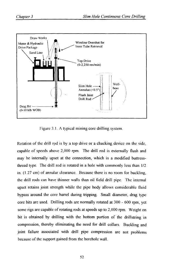
Chapter 3
Draw Works
Motor & Hydraulic Dri ve Package
~dLin\
(
Drag Bit ~----+ (0-10 klb WOB)
Slim Hole Continuous Core Drilling
Wireline Overshot for ~ I neer Tube Retrieval
:~TopDrive D- (0-2,250 rev/min)
I
i Slim Hole 1 '
I) Wellbore
Figure 3.1. A typical mining core drilling system.
Rotation of the drill r9d is by a top drive or a chucking device on the side,
capable of speeds above 2,000 rpm. The drill rod is externally flush and
may be internally upset at the connection, which is a modified buttress
thread type. The drill rod is rotated in a hole with commonly less than 1/2
in. (1.27 cm) of annular clearance. Because there is no room for buckling,
the drill rods can have thinner walls than oil field drill pipe. The internal
upset retains joint strength while the pipe body allows considerable fluid
bypass around the core barrel during tripping. Small diameter, drag type
core bits are used. Drilling rods are nonnally rotated at 300 - 600 rpm, yet
some rigs are capable of rotating rods at speeds up to 2,000 rpm. Weight on
bit is obtained by drilling with the bottom portion of the dril1string in
compression, thereby eliminating the need for drill collars. Buckling and
joint failure associated with drill pipe compression are not problems
because of the support gained from the borehole wall.
52
Chapter 3 Slim Hole Continuous Core Drilling
Most numng bits are diamond impregnated cast bits, used for hard
formations; however, surface set diamond core bits similar to oil field core
heads are also used. The drill bit kerf is very narrow, commonly 0.5 - 1 in.
This makes cutting more efficiently because less formation is actually
drilled up, and speed variation between the inside and outside of the cutting
face is reduced.
Well control equipment, if used at all, usually consists of a ram or bag type
blowout preventer (BOP), an accumulator, and controls. Understanding of
well control practices and of how actually to handle a kick is questionable
and poorly documented within the mining industry. Because the mining
industry is interested in finding mineral deposits, continuous coring is often
practiced. The best way to core continuously is with a wireline retrievable
system. Cores are retrieved by pulling the inner core barrel through the
drillstring by wire line, necessitating doubledrum drilling units. Core
barrels have lock dogs and fishing necks similar to oil field wire line tools.
While a core is pulled, the danger of swabbing a well is reduced by
pumping down the drillstring, against and around the core barrel.
3.5 Continuous Coring Rigs
The main available rigs can be classified in three groups;
1) Slim hole destructive drilling rigs. Many of the small oil drilling rigs or
workover rigs can drill slim holes, but these rigs are not necessarily
designed for continuous coring. One must note the original approach of
the microdrill rig which was conceived merely as an oil rig with reduced
dimensions. This category excludes small mining rigs that are limited in
depth.
53
Chapter 3 Slim Hole Continuous Core Drilling
2) Continuous cable coring mining rigs. These rigs, for the most part, have
no rotat)' table and are designed for coring most of the well length.
Several companies supply rigs able to reach depths of 2,000-6,000 m
(6,096-19,685 ft).
3) Mixed oil drilling rigs. During the last few years, several attempts have
been made to transform oil rigs into coring rigs by fitting them with
mining rods, wireline core barrels, and chuck clamping systems.
3.5.1 Rig Designs
Conventional oil industry drilling rigs are quite effective in destructive
drilling, even in slim holes. However, these rigs can only core limited
lengths with limited efficiency because it is typically necessary to make a
round trip to recover each core barrel.
Conversely, mining drilling rigs drill destructively only in the surface
formations, always drill slim hole diameter, and core continuously for most
of the well. Mining rigs and their equipment are quite effective for these
operations because of the following;
• The smaller size reduces location area (about 9,000 sq. ft with mud pits)
and makes them much lighter than oil rigs.
• The reduction in bulk allows helicopter transport or trailer mounting.
• The power required is low, typically 300-400 hp.
• The drillstring handling system uses a chuck clamping head to provide
rotation and bit weight.
• The all-hydraulic design allows flexible control of weight on bit, drill
rates and rotary speeds. The automated hydraulic controls are necessary
to ensure protection of the fast-rotating drill string, especially in case of
a sudden variation of torque.
54
Chapter 3 Slim Hole Continuous Core Drilling
• The continuous coring system allows recovery of the inner tube of the
core barrel by using a wireline and without tripping the drill string. For
instance, at 2,000 m (6,561 ft), drilling is only interrupted 15-20 min for
every 18-ft core recovered.
3.5.2 Mining Drilling Eq.uipment
Mining rigs range in size from simple, one-man-operated drilling machines
weighing only several thousand pounds up to three-man drilling machines
weighing close to 100,000 Ibm (45 Mg). Most mining rigs are capable of
drilling only 6,000 ft (1829 m) or less, although a few can continuously
core to 14,000 ft (4267 m). Because most mining rigs are hydraulic, the
chuck or top drive systems can rotate the drill rods at variable speeds up to
2,000 rpm, depending on available torque. These systems are also used to
raise and lower the rod hydraulically. The chuck has a stroke ranging from
2 to 11 ft (0.6 to 3.4 m), at which time it must be hydraulically raised to
regrab (chuck) the rod. Drilling rod sizes range from 1. 75 to 5 in. (4.4 to
12.7 cm) OD. The externally flush rod provides a smooth surface that acts
as a bearing shaft inside the small annular clearance wellbore. Drill rod
lengths vary from 3.28 to 19.69 ft (1 to 6 m). A benefit of the mining
system is that each size rod can be used as casing, with the next smaller size
of drill rod able to rotate inside the other pipe.
3.6 Drilling Operations
The technological approach of the mining industry for drilling and coring
slim holes is considerably different from the typical oil industry approach.
Because of the differences in equipment and its applications, an operator
using mining equipment (rigs or rods) will have to adapt its techniques in
55
Chapter 3 Slim Hole Continuous Core Drilling
relation to its knowledge of the technology and to the specifications
required for safety, especially in the area of kick detection and control.
The reduced drill rodlwellbore annular clearance and the fast rotation of the
drillstring require modification of the usual concepts regarding kicks.
Because the annulus containing such a small fluid volume, a kick poses a
serious threat of emptying the well. Thus, kicks must be detected early,
after only a small influx of fluid. The standard procedures for controlling a
kick by circulating the influx after checking surface pressures do not apply
easily. The pressure drop distribution is inverted in comparison to that
found in conventional oil wells. Indeed, as a result of the small annular
clearance, most of the pressure drop occurs in the annulus section. In
contrast, the pressure drop occurs inside the pipe in those wells drilled with
conventional drilling rigs.
3.6.1 Drilling Fluids Hydraulics
Reduced annular clearance and fast pipe rotation contribute to turbulent
flow over most of the well. Thus, many classical well hydraulic models
become inadequate. The solids content in the mud must be kept as low as
possible to avoid forming sludge inside the rods. Sludge built up on the rod
inner wall makes core barrel recovery difficult and sometimes impossible.
Therefore, solids control equipment, such as centrifuges, should be
systematically implemented.
The mining industry has realised the need for a "no-solids" circulating fluid
since the inception of the wireline retrieval core system. As the drill rod is
rotated at high speeds, it acts as centrifuge that can cause solids platting on
the ill. This would not only eventually restrict flow down the rod, but also,
and more importantly, prevent wireline retrieval of the core, which could
cause a rod trip. When possible, the mining industry uses water to core. If
56
CJuzpter 3 Slim Hole Continuous Core Drilling
viscosity is required (e.g., to overcome rod vibration), a polymer is used.
Large amount of sedimentary formation with reactive clays are rarely
drilled by the mining industry. Therefore, the industry has little expertise in
designing oilfield mud systems to inhibit the various formations with
reacti ve clays.
Circulation rates required for the slim hole system vary significantly from
those of conventional oilfield practices, primarily because of the high
annular velocities in the small annular space and the lifting of finer cuttings.
Common flow rates when an HQ rod is used range from 20 to 40 gpm
(1.3xl0-3 to 2.5xl0-3 m3/s), whereas those when the BQ rod is used vary
from 8 to 15 gpm (5.1xl0-4 to 9.5xl0-4 m3/s). Specific mining terminology
is defined in Table 3.1.
57
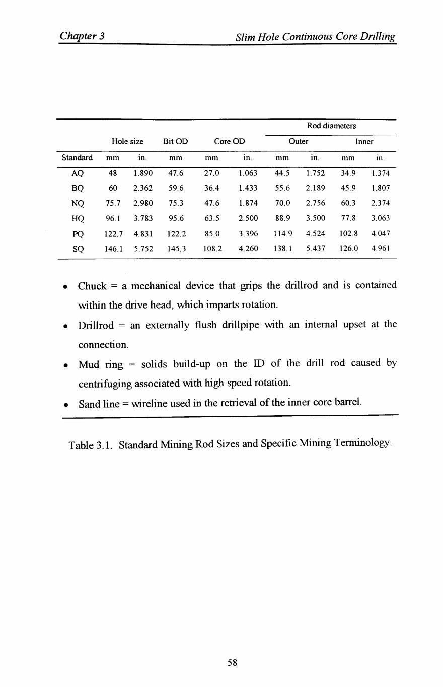
Chapter 3 Slim Hole Continuous Core Drilling
Rod diameters
Hole size BitOD CoreOD Outer Inner
Standard mm tn. mm mm tn. mm tn. mm 111.
AQ 48 1.890 47.6 27.0 1.063 44.5 1.752 34.9 1.374
BQ 60 2.362 59.6 36.4 1.433 55.6 2.189 45.9 1.807
NQ 75.7 2.980 75.3 47.6 1.874 70.0 2.756 60.3 2.374
HQ 96.1 3.783 95.6 63.5 2.500 88.9 3.500 77.8 3.063
PQ 122.7 4.831 122.2 85.0 3.396 114.9 4.524 102.8 4.047
SQ 146.1 5.752 145.3 108.2 4.260 138.1 5.437 126.0 4.961
• Chuck = a mechanical device that grips the drillrod and is contained
within the drive head, which imparts rotation.
• Drillrod = an externally flush drillpipe with an internal upset at the
connection.
• Mud ring = solids build-up on the ill of the drill rod caused by
centrifuging associated with high speed rotation.
• Sand line = wireline used in the retrieval of the inner core barrel.
Table 3.1. Standard Mining Rod Sizes and Specific Mining Terminology.
58
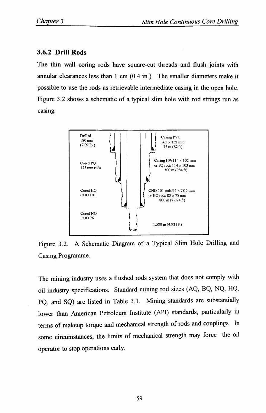
Chapter 3 Slim Hole Continuous Core Drilling
3.6.2 Drill Rods
The thin wall coring rods have square-cut threads and flush joints with
annular clearances less than 1 em (0.4 in.). The smaller diameters make it
possible to use the rods as retrievable intermediate casing in the open hole.
Figure 3.2 shows a schematic of a typical slim hole with rod strings run as
casIng.
Drilled 180nun (7.09 In.)
CoredPQ 123 mmrods
CoredHQ COO 101
CoredNQ COO 76
j l Casing PVC 165 x 152 nun
25 m (82 ft)
CasingHWI14 x 102 mm or PQ rods 114 x 103 mm
300 m (984 ft)
CHD 101 rods 94 x 78.5 mm or HQ rods 83 x 78 nun
800 m (2,624 ft)
1,500 m (4,921 ft)
Figure 3.2. A Schematic Diagram of a Typical Slim Hole Drilling and
Casing Programme.
The mining industry uses a flushed rods system that does not comply with
oil industry specifications. Standard mining rod sizes (AQ, BQ, NQ, HQ,
PQ, and SQ) are listed in Table 3.1. Mining standards are substantially
lower than American Petroleum Institute (API) standards, particularly in
terms of makeup torque and mechanical strength of rods and couplings. In
some circumstances, the limits of mechanical strength may force the oil
operator to stop operations early.
59
Chapter 3 Slim Hole Continuous Core Drilling
3.6.3 Cementing
Cementing volumes can be reduced using drill rods as a retrievable casing
string. Because of the high pump pressures required to overcome the
increased friction in the small annulus, cementing operations might become
difficult with respect to channelling behind pipe and fracturing of weak
formations. Reaming the well before running casing may offer one solution
to this problem. The small volumes of cement required make it possible to
search for more adaptable substitutes for working in those small diameters.
3.6.4 Bits
Drag type core bits are used almost exclusively by numng drilling
compames. These bits, if properly designed, are ideal for drilling mineral
type formations. Typical formations penetrated in minerals exploration are
much harder, more competent, and more uniform than those drilled by the
oil industry. Therefore, direct application of mining bit practices to
sedimentary formations will not necessarily yield economic results. The
impregnated diamond bit is used most often in mining coring. This bit has
very small diamonds (310 to 525 diamond particles per carat) continuously
embedded within a tungsten carbide matrix that wears as formation is
drilled, exposing new cutting surfaces. Surface set diamond core bits are
also used, but to a lesser extent, on softer formations. Polycrystalline
diamond compact (PDC) bit technology is virtually unused in the mining
industry.
Drag bits rotated at high speeds can penetrate the rock efficiently with a low
weight on bit (WOB). A typical WOB range is from 2,000 to 10,000 lb
(8896 to 44482 N). Drag bits are susceptible to catastrophic failure if the
formation changes abruptly and the bit becomes "buried" and fluid starved.
Therefore, a precise bit advance system is desired~ however, this system
60
Chapter 3 Slim Hole Continuous Core Drilling
does not exist on most mining rigs, although the design of one is very
adaptable to a drilling machine with hydraulic controls.
3.6.5 Well Control
Well control practices generally are not a concern to the mining industry
due to the fact that most formations penetrated in mining do not contain
hydrocarbons. Use of this system for hydrocarbon exploration requires a
thorough understanding of the physics associated with well control in the
slim hole. Investigation of the system's physics reveal that slim hole well
control is very possible. (Bode et aI., 1989) give a detailed discussion of
slim hole well control physics and practices.
3.6.6 Core Retrieval and Processing
One of the main intentions of continuous coring operations is the gathering
of as much information as possible. Thus, immediate core processing and
analysis must be particularly well organised. With a proper core lab set-up,
a complete set of data could be measured on site, including such parameters
as: porosity, permeability, saturation, geochemistry, gamma ray, magnetic
susceptibility, fluorescence, and hydrocarbon analysis. Unfortunately, a
suitable well site service for core processing does not seem to be available
yet.
Moreover, mud logging operations are more productive because cores are
analysed instead of cuttings, which are virtually non-existent when coring.
Core samples are large and less contaminated by mud with a precise depth
of origin known. On site core processing should make it possible to reduce
to a minimum the amount of logs required. Most of the standard electric
line logs are available for diameters down to 2 7/8 in., and production
61
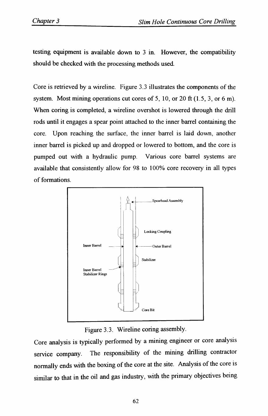
Chapter 3 Slim Hole Continuous Core Drilling
testing equipment is available down to 3 in. However, the compatibility
should be checked with the processing methods used.
Core is retrieved by a wireline. Figure 3.3 illustrates the components of the
system. Most mining operations cut cores of 5, 10, or 20 ft (1.5, 3, or 6 m).
When coring is completed, a wireline overshot is lowered through the drill
rods until it engages a spear point attached to the inner barrel containing the
core. Upon reaching the surface, the inner barrel is laid down, another
inner barrel is picked up and dropped or lowered to bottom, and the core is
pumped out with a hydraulic pump. Various core barrel systems are
available that consistently allow for 98 to 1000/0 core recovery in all types
of formations.
Inner Barrel
Inner Barrel Stabilizer Rings
Locking Coupling
14-----Outer Barrel
Stabilizer
Core Bit
Figure 3.3. Wireline coring assembly.
Core analysis is typically performed by a mining engineer or core analysis
servIce company. The responsibility of the mining drilling contractor
normally ends with the boxing of the core at the site. Analysis of the core is
similar to that in the oil and gas industry, with the primary objectives being
62
Chapter 3 Slim Hole Continuous Core Drilling
to determine the reservoir (mineral) properties; little consideration is given
to true geological and geophysical evaluation, although the recent mining
literature reflects more of an interest in evaluating the complete core.
3.7 Challenges to Oilfield Drilling
The adaptation of slim exploration wells to the oil and gas industry brings
new challenges to the oil field;
• Technology must improve some of the problems and limitations of slim
hole drilling and improve the real-time analysis of cores and logs.
• Furthermore, formation testing in small diameter wells needs to be
considered and studied.
• Safety of the rig and rig crew presents additional problems in areas
including kick control, early gas detection, and implementation of
explosion-proof standards for mining rigs.
• With the development of core hole drilling as a tool for the
explorationist and reservoir engineer, exploration strategies may change
as a result of the large amount of raw information immediately available . at reduced costs. This approach may result in a redistribution of the
respective input from and expenses to the geophysical and drilling
departments.
63
Chapter 3 Slim Hole Continuous Core Drilling
3.8 Considerations for Oilfield Drilling
Slim hole exploration wells should be analysed as an option for an
exploration project in the following circumstances:
• If a significant part of the drilling budget is for logistics.
• If difficulties are expected as a result of climate, environment, or site
access.
• If seismic operations become complicated, costly, or difficult to interpret.
• If a well is re-entered for deepening.
• If there is a need particular or precise information supplied by continuous
cores, including: stratigraphy, sonic velocities, formation age and
maturation, source rock and cap rock nature, reservoirs, and formation
fluids.
• If a field is evaluated for extension (for example, before expiration of
permits). Because of the present limitations of slim hole exploration,
especially concerning safety, kick detection, and well control, it appears
that slim hole explorations are appraisal purposes than for wildcat
exploration.
• Disposal of drill cuttings; lower volume for slim hole.
64
Chapter Four
CORE DRILLING
4.1 Introduction
The process of coring and core analysis has advanced considerably in recent
years, especially in light of sophisticated and highly technical forms of
investigation such as scanning electron microscopy, x-ray diffraction and
thin section analysis.
Cores are the only way to supply intact specimens of the formation
anatomy. Direct measurements on core samples furnish data not available
from any other source, and cores afford the only opportunity for visual
examination of the rock aside from cuttings analysis. Thus cores when
viewed with an intelligent eye, yield geologic and engineering information
that will increase understanding of the presence, quantity and distribution of
formation hydrocarbons, and ultimately will aid in selection of processes to
maximise their profitable recovery.
Of all commonly available coring methods, the conventional core analysis,
is the most important source of information in that it furnishes measured
values of basic rock properties. Porosity, permeability, residual fluids,
lithology and texture are some of the parameters that characterise a core
vertically, and representative samples are commonly taken every foot (and
more frequently when core examination indicates the need). A quick look
at these cores and their tabulated and plotted data identifies zones of
greatest storage capacity (porosity), greatest flow potential (permeability)
and the presence and magnitude of residual oil. Relative changes in these
65
Chapter 4 Core Drilling
properties with depth are easily observed, and average properties of selected
zones can be compared for relative quality. Grain size, an indication of
sorting, colour of the rock, presence of laminations and other important
structures are described. Fractures, intensity and distribution of oil
fluorescence are also reported Data such as grain size distribution, grain
density and acid solubility typically are furnished as supplementary data on
request.
A drilling programme of boreholes to depths up to 2000 m for the
investigation of possible sites for the repository for the disposal of radio
active waste included the requirement for high quality continuous core
drilling. These special requirements prompted the adoption of a blend of
oilfield, mining and geotechnical exploration equipment and procedures to
achieve the various objectives within the quality standards.
This chapter summarises the main elements of the equipment, systems and
procedures adopted and presents some data on performance comparisons
between a mining rig approach and that using a modified conventional
oilfield rig. Comments on the application of this experience to slim hole
continuous core drilling for oil and gas exploration and exploitation, are
made in chapter six.
66
Chapter 4 Core Drilling
4.2 Field Programme
In order to investigate the performance of various types of impregnated core
bit and drilling operations, this study focuses on data obtained from an
investigative drilling programme. In this special investigation programme,
the integration of oilfield, mining and geotechnical exploration technologies
including several elements which are important in the application of slim
hole methods for oil and gas exploration is analysed Many of the technical
issues associated with a slim hole approach is addressed in the development
and application of the drilling, coring equipment and systems.
4.2.1 Geotechnical Investigation Drilling Programme
A programme of boreholes to depths up to 2000 m for the investigation of
potential sites for the UK national repository for the disposal of low and
intermediate level radio active waste included the requirement for high
quality continuous coring through a range of geologies, a 159 mm (6-1/4 in)
minimum diameter hole for a comprehensive wireline logging programme
and a suite of testing both during drilling and at the end of each borehole
interval. The requirement for a deep high quality geotechnical investigation
programme provided a rare opportunity to integrate technologies from
various drilling applications to develop a routine exploration method for this
type of special geoscientific investigation and to help evaluate the suitability
of slim hole methods for exploration and exploitation drilling in the oil and
gas industry.
The investigation is part of a geological and hydrogeological study for
potential sites for a deep, low and intermediate level radio active waste
repository which will eventually be mined at a depth of 500-1000 m below
the surface. Two sites were being considered at the start of the
67
Chapter 4 Core Drilling
investigation at Sellafield,· Cumbria, England and at Dounreay, Caithness,
Scotland. The preferred site at which the current work is being
concentrated is at Sellafield.
The two sites presented an opportunity to gain expenence with a
standardised system in different conditions from site size to geology and
support logistics considerations. The unusual specification for continuously
cored holes using a wireline system and enlargement to allow the
installation of standard oilfield casing in standard hole sizes required some
innovation. Where possible available equipment was utilised on cost
grounds and in view of the limited lead time available for mobilisation. The
package adopted was essentially contractor designed to meet an end product
specification.
The geologies of the two sites are both variant of the crystalline basement
under sedimentary cover repository scenario. At Sellafield, the generalised
succession is principally a Permo-Triassic sequence comprising abrasive
fine to medium grained sandstone, shale and poorly sorted breccias
overlying Carboniferous Limestone and a basement of lower Palaeozoic
age, the Borrowdale Volcanic Group. The Permo-Triassic includes the St
Bees Sandstone, a formation noted for its abrasivity. Bit records from wells
in the formation in the adjoining Irish Sea Basin show abnormal gauge
wear. The Borrowdale Volcanic Group comprises welded tuffs, with
interbeds of volcanic breccia and some intrusive andesite sills.
At Dounreay, a Devonian sequence of interbedded siltstones and sandstones
some 400-500 m thick overlies a basement complex of metamorphic rocks
of the Precambrian Moinian series. The Moinian rocks are very strong and
abrasive with many quartz rich feldspar veins.
68
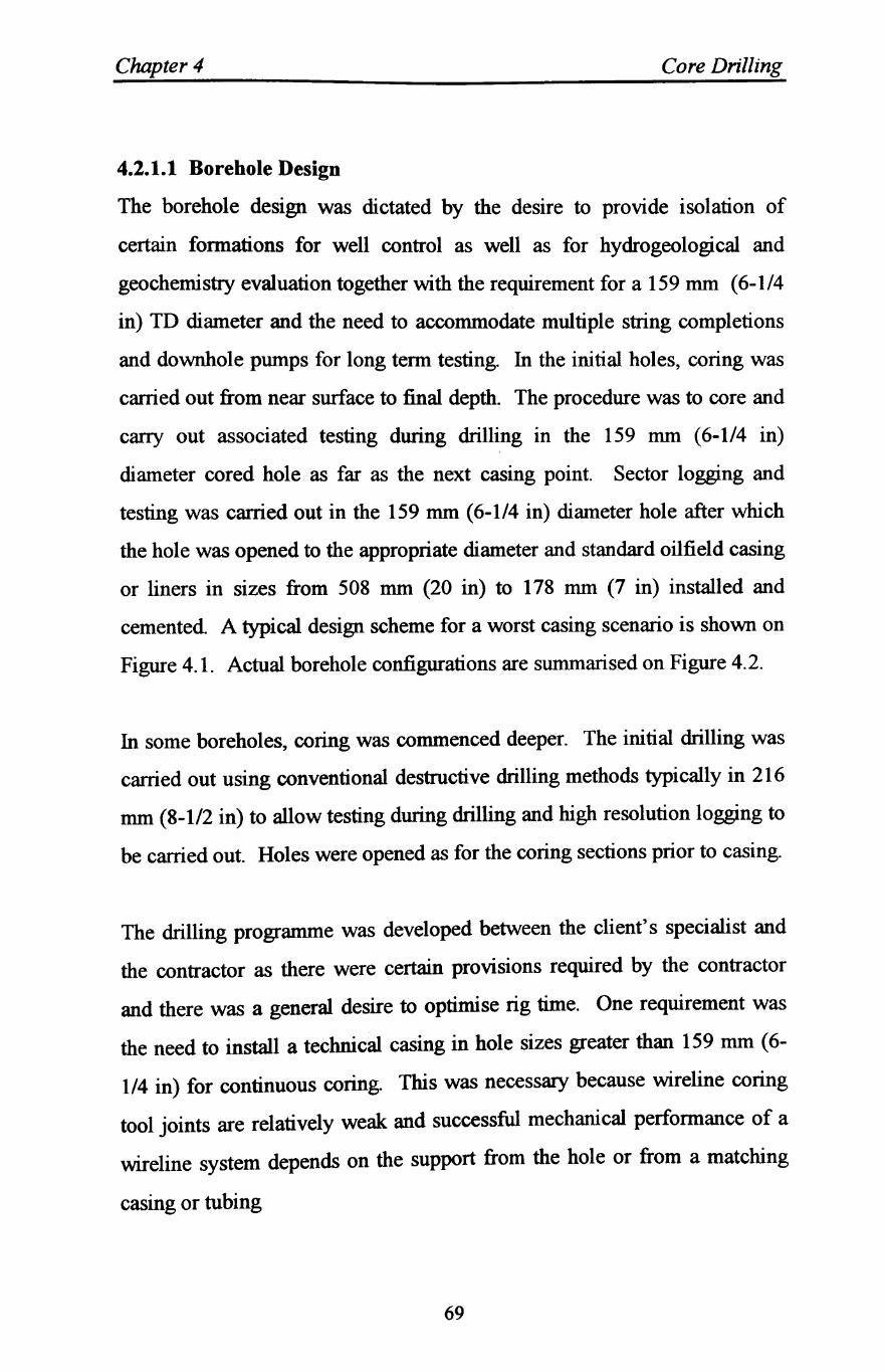
Chapter 4 Core Drilling
4.2.1.1 Borehole Design
The borehole design was dictated by the desire to provide isolation of
certain formations for well control as well as for hydrogeological and
geochemistry evaluation together with the requirement for a 159 mm (6-1/4
in) TD diameter and the need to accommodate multiple string completions
and downhole pumps for long term testing. In the initial holes, coring was
carried out from near surface to final depth. The procedure was to core and
carry out associated testing during drilling in the 159 mm (6-1/4 in)
diameter cored hole as far as the next casing point. Sector logging and
testing was carried out in the 159 mm (6-1/4 in) diameter hole after which
the hole was opened to the appropriate diameter and standard oilfield casing
or liners in sizes from 508 mm (20 in) to 178 mm (7 in) installed and
cemented. A typical design scheme for a worst casing scenario is shown on
Figure 4.1. Actual borehole configurations are summarised on Figure 4.2.
In some boreholes, coring was commenced deeper. The initial drilling was
carried out using conventional destructive drilling methods typically in 216
mm (8-1/2 in) to allow testing during drilling and high resolution logging to
be carried out. Holes were opened as for the coring sections prior to casing.
The drilling programme was developed between the client's specialist and
the contractor as there were certain provisions required by the contractor
and there was a general desire to optimise rig time. One requirement was
the need to install a technical casing in hole sizes greater than 159 mm (6-
1/4 in) for continuous coring. This was necessary because wireline coring
tool joints are relatively weak and successful mechanical performance of a
wireline system depends on the support from the hole or from a matching
casing or tubing
69
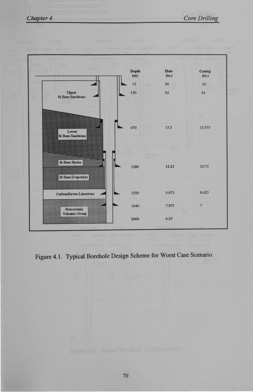
Chapter 4 Core Drilling
Depth Hole Casing (m) (an.) (an.)
15 30 26
Upper 150 24 24 St Bees Sandstcne
670 17.5 13.375
1280 12.25 10.75
1520 9.875 8.625
1640 7.875 7
2000 6.25
Figure 4.1. Typical Borehole Design Scheme for Worst Case Scenario.
70
Core Drilling
SZ S3 S4
B~EHOLE CASING BOREHOLE CASING BOREHOLE CASING
d,orh dl.1"~l!'r d~pth dl.1m~ar C;eorn dlam~r~r deoth dl.1.,.r~r deorh d'.1_~r d~trl d,arltrt"t"
Iml I,nl Iml I,n 1 Iml II n I Iml Ilnl Iml linl Iml I'nl
I , Z7 26 27 .... ,0 17 \'z : 13 ;,! 26 : "20 13 1t& ,
156 154 15 a 155 157 1SS
( I Ire. 9~ 12 "'r. 9'8 I
I , 395 17 "2 1137& 0"2 3':13 ,
7 I I. 1 1 £.a 0 .....
I teenn,cal t.93 1.90 I , 510 5 "2 507 .J 7 casing
11'chnIC<l( 569 C;!~lnq
673
S :",
12\ ,
: 1 O-re.
6 "<.
I 1291 1: :Iz i 2 91 I 1260 13 09 1297
.J 7 teoct"rnal c. SINj
1610
195Z
01 02
SO REHOLE ~..!.SING SOREHOLE CASING
deorh dla ml!'r~ deom dl~"~ rer deotn d i illIW rt-f" dec trl dl.1~r?f"
Iml "nl Iml I inl Iml lin/ Iml Ilnl
a ,
~ J .5 .., os I
I ' :0 ........, -- 76 ']T;l;'" ,
l'Z2 J l ~ 1';'\ 17'vz I : 13~! , l
11.1 ,
~5 5 ~ i I , ~57
I 157 rl'(nnIC~'
i2 Ire. J" caslnq ! 9'1,
391. !.12 J
;'10 r~cnnlcal (all~
6 :/~
6 \,
965
Figure 4,2, Actual Borehole Configurations,
71
L'hapter 4 Core Drilling
string. In effect, the small mud filled annulus between the pipe and casing
or hole provides continuous support and reduces flexing and vibration in the
string.
For this programme, a 178 mm (7 in.) casing was used for this purpose and
installed after each permanent casing was drilled out after cementing. A
typical arrangement for the technical casing is shown in Figure 4.3. The
casing was hung free at the bottom in the larger casing and centralised as
required A bell entry guide was machined in the lowest casing collar to
ensure free passage of the coring, logging and testing assemblies. A seal
was provided in the wellhead assembly.
One noteworthy feature of the borehole design was the use of a sub sea or
compact type wellhead which facilitated the installation and removal of
both permanent and temporary casings without the necessity to nipple down
the BOP stack. This was a convenient expedient particularly for the more
complex casing schemes and it proved very cost effective.
4.2.1.2 Drilling Rigs and Equipments
Three rigs have been used to date on the project. Two are 3000 m capacity
diesel electric land rigs modified with electric driven 800 hp (540 kW)
hydraulic power packs, hydraulic top drive units and specialist heavy duty
wireline coring facilities. The third is a heavy duty mining drilling rig
which included specific features for deep coring.
72
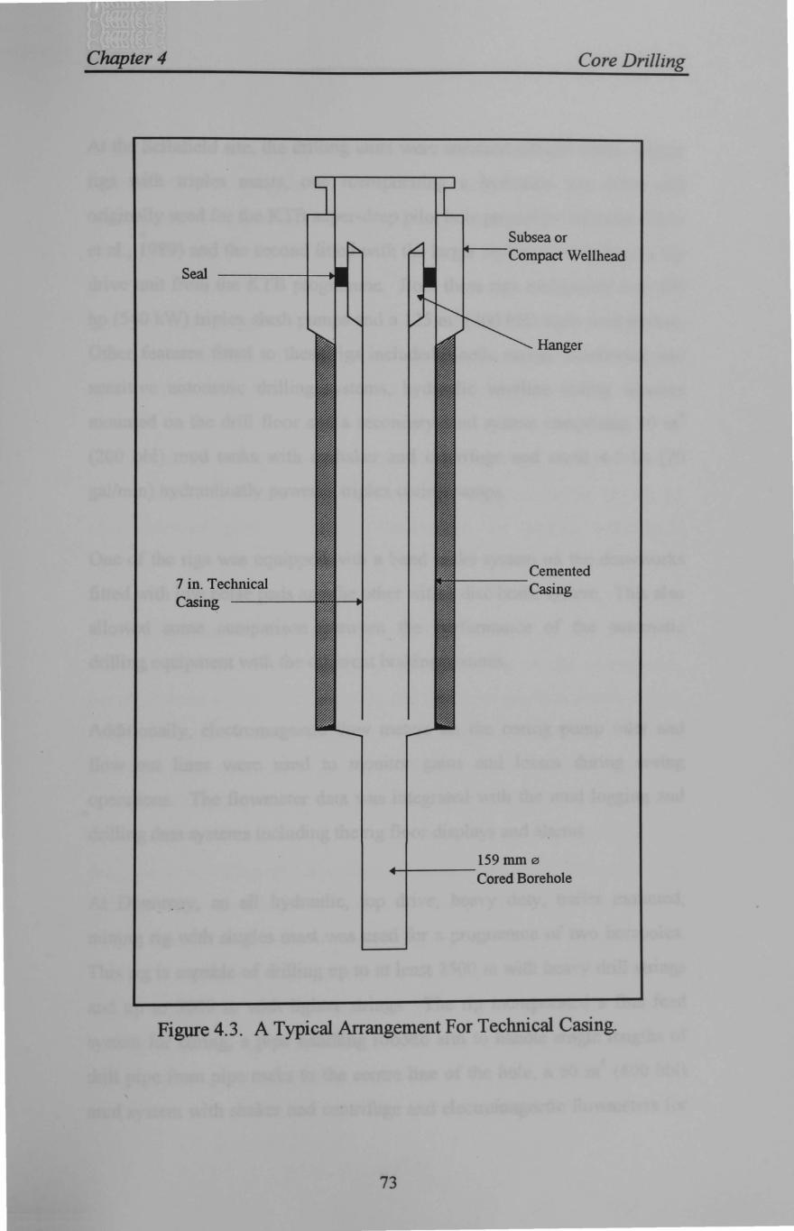
Chapter 4
Seal
7 in. Technical Casing ----
Core Drilling
Subsea or --Compact Wellhead
Hanger
Cemented ----
Casing
159 mm 0 +-+---
Cored Borehole
Figure 4.3. A Typical Arrangement For Technical Casing.
73
Chapter 4 Core Drilling
At the Sellafield site, the drilling units were standard oilfield diesel electric
rigs with triples masts, one incorporating a hydraulic top drive unit
originally used for the KTB super-deep pilot hole project in Germany (Chur
et al., 1989) and the second fitted with the larger replacement hydraulic top
drive unit from the KTB programme. Both these rigs incorporate two 800
hp (540 kW) triplex slush pumps and a 125 m3 (800 bbl) main mud system.
Other features fitted to these rigs included kinetic energy monitoring and
sensitive automatic drilling systems, hydraulic wireline coring winches
mounted on the drill floor and a secondary mud system comprising 30 m3
(200 bbl) mud tanks with a shaker and centrifuge and small 4.5 lis (70
gal/min) hydraulically powered triplex coring pumps.
One of the rigs was equipped with a band brake system on the drawworks
fitted with low noise pads and the other with a disc brake system. This also
allowed some comparison between the performance of the automatic
drilling equipment with the different braking systems.
Additionally, electromagnetic flow meters on the coring pump inlet and
flow out lines were used to monitor gains and losses during coring
operations. The flowmeter data was integrated with the mud logging and
drilling data systems including the rig floor displays and alarms.
At Dounreay, an all hydraulic, top drive, heavy duty, trailer mounted,
mining rig with singles mast was used for a programme of two boreholes.
This rig is capable of drilling up to at least 2500 m with heavy drill strings
and up to 3000 m with lighter strings. The rig incorporated a fine feed
system for coring, a pipe handling robotic arm to handle single lengths of
drill pipe from pipe racks to the centre line of the hole, a 60 m3
(400 bbl)
mud system with shaker and centrifuge and electromagnetic flowmeters for
74
Chapter 4 Core Drilling
monitoring flow in and flow out as part of the mud logging and drilling data
facility. A 300 hp duplex (200 kW) mud pump and an identical triplex
coring pump to those units provide for coring at Sellafield were included in
the rig inventory.
Each rig was equipped with 4-1/2 in or 4 in API drill pipe strings and
associated drill collars for conventional drilling and hole opening together
with 3-1/2 in API drill strings and 2-7/8 in tubing for testing.
Site layouts for the rigs and associated equipment were accommodated in
about 4250 m2 for the large oilfield units and 1800 m2 for the mining rig
plus additional space for offices, laboratories, car parking and tubular
stores.
4.2.1.3 Wireline Coring System
The borehole specification required hole diameters in the continuously
cored intervals of 159 nun (6-1/4 in) principally to accommodate borehole
imaging tools for fracture mapping. This diameter requirement could be
accommodated with the largest size of heavy duty wireline equipment
available. The string selected is one of a suite of wireline strings which has
been widely used over the last 10-15 years in Europe These strings were
designed as a nesting set for drilling conditions where difficult and varied
geology necessitates a system where the string can be used as casing if
drilling can not be continue without casing due to hole conditions (petersen,
1987). The principal data on this suite of strings are given in Table 4.1.
These strings are rated on strength criteria for use up to 4000 m.
Noteworthy is that the drilling sizes allow the use of standard oilfield casing
and tubing sizes which are noted in the table.
75
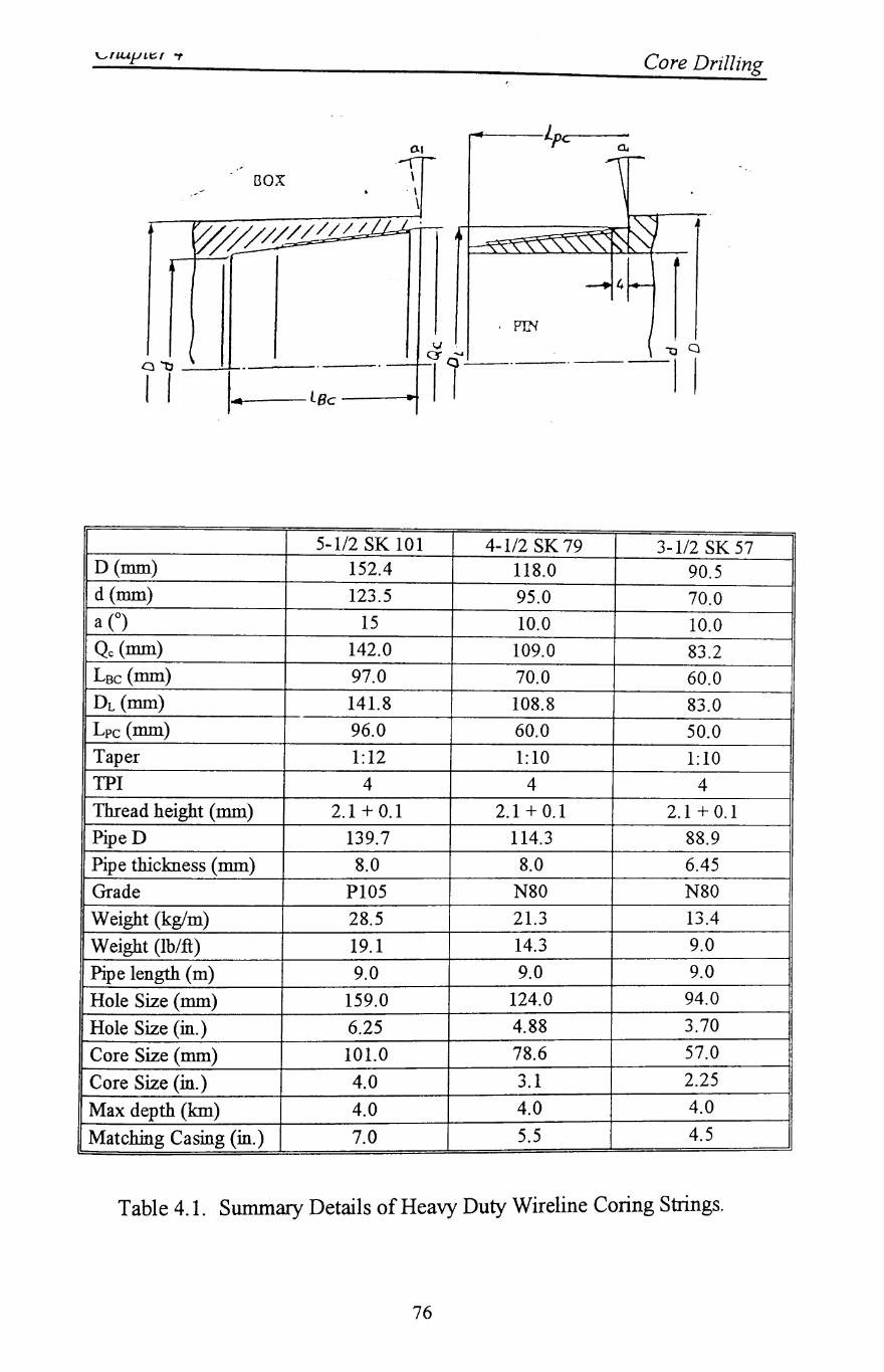
--\ r--'
nox \ ~ ~ . - \
\
W///////////j I'
G \
v C5
"tJ .
I I I Lee ~ ..
5-1/2 SK 101 D(mm) 152.4 d(mm) 123.5 a (0) 15 Qc (mm) 142.0 Lsc (mm) 97.0 DL (mm) 141.8 Lpc (mm) 96.0 Taper 1:12 TPI 4 Thread height (mm) 2.1 + 0.1 PipeD 139.7 Pipe thickness (mm) 8.0 Grade PI05
Weight (kg/m) 28.5
Weight (lb/ft) 19.1
Pipe length (m) 9.0
Hole Size (mm) 159.0
Hole Size (in.) 6.25
Core Size (mm) 101.0
Core Size (in.) 4.0
Max depth (km) 4.0
Matching Casing (in.) 7.0
f
~--/..p~r--a.
. PIN
Core Drilling
"'0 C)
-II
4-1/2 SK 79 3-1/2 SK 57 118.0 90.5 95.0 70.0 10.0 10.0 109.0 83.2 70.0 60.0 108.8 83.0 60.0 50.0 1:10 1:10
4 4 2.1+0.1 2.1+0.1
114.3 88.9 8.0 6.45
N80 N80 21.3 13.4
14.3 9.0
9.0 9.0
124.0 94.0
4.88 3.70
78.6 57.0
3.1 2.25
4.0 4.0
5.5 4.5
Table 4.1. Summary Details of Heavy Duty Wireline Coring Strings.
76
Chapter 4 Core Drilling
For this coring programme, the largest size string of the suite was used
which gave the desired 159 mm hole diameter and nominal 100 mm (4 in)
core.
With the objective of optimising core quality and surface handling, a UPVC
corebarrelliner was utilised in the inner tube of the corebarrel reducing the
core size to 95 mm. The use of a liner results in an increased bit kerf
thickness and a less advantageous area ratio which generally decreases
coring performance especially in strong, abrasive rocks, however, this was
accepted as core quality was the foremost objective of the coring system.
This type of liner is widely used in quality geotechnical and mining
investigations to some 200 m depth where high quality cores are essential
for engineering purposes. This particular material had not been used
previously for holes deeper than 400 m. The liners were 2.65 mm thick and
manufactured to fine tolerances and cut to a precise length so that insertion
on site was simple. The manufacturing specification was as follows:
Length
Outside diameter
Inside diameter
Inner barrel ID
Liner clearance
Core diameter
Core clearance
6265.00mm +/2.0mm
102.75mm +/0.10mm
96.75mm +/0.15mm
104.00 mm nominal
103.50 mm minimum
0.325 mm minimum
95.00 mm nominal
0.8 mm nominal minimum
The liner material comprises Wellvic V8 167, a UPVC especially
manufactured for stability on extrusion and known to be temperature stable
77
Chapter 4 Core Drilling
up to 60° C. No liner distortion was noted with bottom hole temperatures
approaching 60° C and circulating temperatures up to 40° C.
Even though each liner was subjected to a quality inspection at the point of
manufacture, every length of core barrel liner was again checked on site for
visual defects and internal and external diameters.
On recovery of the inner barrel, liners were extruded horizontally from the
corebarrel inner tubes with water pressure acting against a sealed plug
machined to fit the top of the liner and which allowed the extrusion force to
be carried by the liner wall with no compression of the core. The core
quality achieved with this system has been excellent. A corebarrellength of
6 m was selected on the grounds that this was probably equivalent to the
projected average run length and it facilitated surface handling without
introducing especially heavy handling equipment and the risk of damage
during handling. This was a decision which has proven to be appropriate in
this case, but for other applications, a longer corebarrel could be used. The
outer barrel of the coring system is identical to the coring drill string.
Identical in hole wireline coring equipment was used on all rigs including
corebarrels, corebarrel stabilisers, core catcher assemblies inner barrels,
liners and wireline retrieval equipment. Pipe handling on the conventional
rig was achieved using conventional slip type elevators as the tool joint
upset gives sufficient assurance that the elevators will grip. It is more usual
with wireline strings to use lift subs and associated elevators which
increases the tripping time due the need to install and remove the lift plugs.
On the mining rig, the power swivel incorporates a power slip system and
elevators are not required.
78
--------------------
Chapter 4 Core Drilling
The wireline coring system allows the sample barrel containing the core in
the liner to be recovered from the borehole using an overshot and wireline
so significantly reducing the round trip time to recover core. A second
inner tube is returned to the corebarrel at the bottom of the string by free
fall with the restriction afforded by the small annular clearance providing
the necessary braking effect to limit the landing impact on the landing ring.
Tripping of the drill string was only required where a bit change was
necessary or to facilitate testing and/or logging.
The design and construction of wireline drilling strings requires careful
analysis. The principal difference to a normal API drill string is that the
tool joint is relatively weak to allow the passage of the corebarrel inner tube
through the connection. The design of the tool joint controls the strength
and hence depth rating of the string.
During the planning stage of the KTB super-deep pilot hole in Germany,
various wireline coring strings were reviewed for their suitability for
drilling the 4000 m deep initial scientific borehole. The heavy duty strings
subsequently used for the Sellafield and Dounreay investigations were
included in that study which included finite element analysis of the tool
joints. The study concluded that these strings were capable of drilling to
4000 m depth on strength grounds. The actual string eventually used in the
KTB programme was of similar design, but with a 152 mm (6 in) hole size
and non upset pipe necessitating the use of lift subs.
The manufacturing process of the tube for wireline coring strings must also
be considered carefully. With tool joint strength so critical and the
thickness of metal limited, good quality, uniform wall thickness pipe is
essential. Both seamless and welded tube has been used successfully in the
79
Chapter 4 Core Drilling
manufacture of this suite of wireline conng pipe. For dimensional
accuracy, the welded pipe is preferred particularly for the smaller sizes.
Suitable tube used for this wireline coring system is manufactured routinely
in all sizes by the computer aided high frequency inductive welding process.
Current welding technology, advanced processes and quality control during
manufacture provides a high quality tubing for pipe applications.
In the case of the tube used for this investigation programme, lead time on
welded pipe was such that a seamless alternative had to be adopted, but the
grade is P-I05 as against the N-80 grade normally used when welded tube is
used. Tool joints are friction welded to the pipe. Tool joints on this heavy
coring pipe are such that a thin hard band strip can be included to increase
abrasion resistance and hard banding was included on all pin ends of the
pipe used for this investigation.
Pipe failure with heavy duty strings are very rare and no in hole failure has
been experienced to date with the 5-1/2 in string in use at Sellafield and
Dounreay. However, a strict preventative inspection programme is in
operation and all pipe run in the compression zone is inspected every 100
rotating hours and the pipe cycled in the string. The pipe is checked against
a wear criteria similar to the API classification. Th~ criteria used is
presented in Table 4.2. As a guide, wireline pipe life is typically one tenth
that of an equivalent API drill string and hence pipe costs are relatively
high.
80
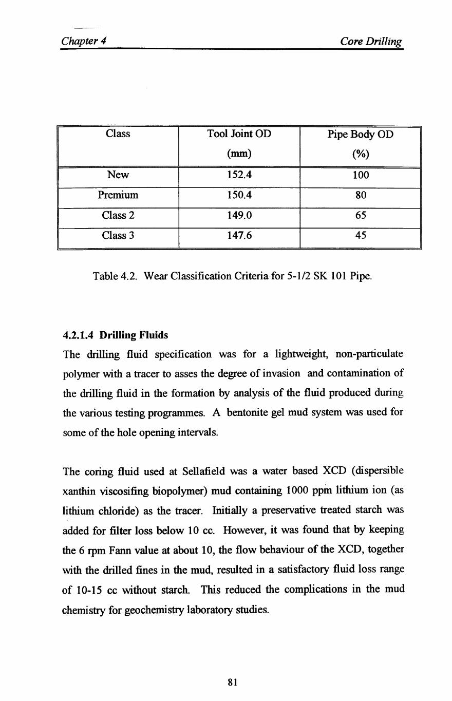
Chnpter 4 Core Drilling
Class Tool Joint OD PipeBodyOD
(mm) (%)
New 152.4 100
Premium 150.4 80
Class 2 149.0 65
Class 3 147.6 45
Table 4.2. Wear Classification Criteria for 5-1/2 SK 101 Pipe.
4.2.1.4 Drilling Fluids
The drilling fluid specification was for a lightweight, non-particulate
polymer with a tracer to asses the degree of invasion and contamination of
the drilling fluid in the formation by analysis of the fluid produced during
the various testing programmes. A bentonite gel mud system was used for
some of the hole opening intervals.
The coring fluid used at Sellafield was a water based XCD (dispersible
xanthin viscosifing biopolymer) mud containing 1000 ppm lithium ion (as
lithium chloride) as the tracer. Initially a preservative treated starch was
added for filter loss below 10 cc. However, it was found that by keeping
the 6 rpm Fann value at about 10, the flow behaviour of the XCD, together
with the drilled fines in the mud, resulted in a satisfactory fluid loss range
of 10-15 cc without starch. This reduced the complications in the mud
chemistry for geochemistry laboratory studies.
81
Chapter 4 Core Drilling
The target Fann rheometer reading corresponded in this fluid to a Marsh
funnel viscosity of between 38 and 50 slqt which became established as a
satisfactory range. The plastic viscosity remained below 8 cp reflecting the
low solids content which ranged between a trace and 2%, the yield point
ranged between 15 and 25 lb/ff depending on the polymer concentration
and gel strengths ranged from 518 to 10/15 Ib/ft2. The formations were such
that visual oilfield variables and problems associated with maintaining an
inhibitive water based fluid while drilling in sedimentary lithology did not
occur.
The lithium ion concentration was required to be maintained within 2% of
1000 ppm, i.e. between 980 and 1020 ppm. This level was necessary to
elevate the concentration above the background level. Five or six flow line
samples were taken each day and the concentration checked.
Fluid densities were generally very low in the range 1.0 and 1.04 SG (8.33
to 8.65 ppg). Torque became a problem in the long open sections in some
holes and after some experimentation, copolymer beads were added to
increase the lubricity. This expedient was chosen as the beads were
relatively inert and the least likely additive to cause any concern to the
geochemistry analysis. A concentration of 1 % by volume reduced torque
by 40%.
Solid control equipment used on all rigs during coring comprised a shale
shaker and 50 gpm (3 lis) centrifuge. During hole opening and open hole
drilling with mud, shakers and mud cleaners were used
82
Chapter 4 Core Drilling
4.3 Hole Opening and Continuous Coring
Open hole drilling was carried out conventionally. Hole operung at
Sellafield was achieved with nonnal hole openers in appropriate assemblies
with rock bits being adapted as an expedient in some of the stronger rocks
to reduce the risk of tool failure and increase the speed. Hole opening was
carried out in stages from 159 mm (6-1/4 in ) to 216 mm (8-1/2 in) then to
311 mm (12-1/4 in) and finally where necessary to 445 mm (17-1/2 in).
In the initial borehole at Dounreay, hole opening was carried out using
down-the-hole hammers and insert hole opener bits with air and foam flush
in a single pass from the 159 mm (6-1/4 in.) cored hole diameter to the final
size. This method was selected due to the strong nature of the rocks and,
despite significant water flow in some intervals, these operations were vel)'
successful. In the 159 mm to 311 mm (12-1/4 in.) interval, some 400 m
long, the hole opening was achieved in 64 hr with one hammer hole opener
bit. Air usage was a maximum of 2300 felm with a 2500 kg weight-on-bit.
Continuous coring using the 139.7 mm (5-1/2 in) heavy duty wireline
coring system was carried out in all holes over part or all of the hole depth.
The coring was carried out using a conventional wireline coring procedure
used widely in the geotechnical investigation, mineral and coal exploration
industries. Rotation was provided by hydraulic top drive units at rotational
speeds generally in the range of 150-220 RPM with corresponding weights
on core bits of 1500-2500 kg. Core recovery and quality were the main
objectives.
A routine was developed to optimise rig time using additional inner tubes,
all of which were interchangeable within the system, to reduce non drilling
83
Chapter 4 Core Drilling
time and all components of the coring system were carefully checked as part
of the quality system adopted for the project.
Coring was interrupted each 50 m to allow testing to be carried out to
determine the environmental pressure in the 50 m interval. This
necessitated tripping the coring string and running a testing assembly on a
testing string. At Sellafield, all pipe was racked in the rig mast, but at
Dounreay, all pipe had to be laid down each trip with the singles rig,
although this procedure was assisted by the use of the pipe handling device
which was added later to the rig to improve tripping speeds.
All boreholes were drilled within the specified verticality tolerance of 10°.
Controlled drilling with the wireline coring system resulted in actual
inclinations at total depth ranging from 0.9° to 6.4°.
84
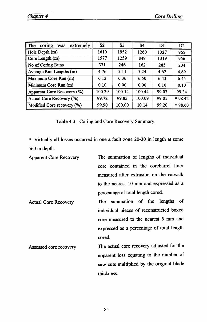
Chapter 4 Core Drilling
The coring was extremely S2 S3 S4 Dl D2
Hole Depth (m) 1610 1952 1260 1327 965 Core Length (m) 1577 1259 849 1319 956
No of Coring Runs 331 246 162 285 204
Average Run Lengths (m) 4.76 5.11 5.24 4.62 4.69
Maximum Core Run (m) 6.12 6.36 6.50 6.43 6.45
Minimum Core Run (m) 0.10 0.00 0.00 0.10 0.10
Apparent Core Recovery (%) 100.39 100.14 100.44 99.03 99.34
Actual Core Recovery (%) 99.72 99.83 100.09 99.05 * 98.42
Modified Core recovery (%) 99.90 100.00 10.14 99.20 * 98.60
Table 4.3. Coring and Core Recovery Summary.
* Virtually all losses occurred in one a fault zone 20-30 in length at some
560 m depth.
Apparent Core Recovery
Actual Core Recovery
Assessed core recovery
The summation of lengths of individual
core contained in the corebarrel liner
measured after extrusion on the catwalk
to the nearest 10 mm and expressed as a
percentage of total length cored
The summation of the lengths of
individual pieces of reconstructed boxed
core measured to the nearest 5 mm and
expressed as a percentage of total length
cored
The actual core recovery adjusted for the
apparent loss equating to the number of
saw cuts multiplied by the original blade
thickness.
85
Chapter 4 Core Drilling
4.4 Well Control
Perhaps the most important aspect in the application of wireline coring
systems to deep drilling in potential hydrocarbon bearing formations is the
question of well control. This has been addressed by others developing the
use of slim hole methods for oil and gas exploration and exploitation,
particularly that published in relation to the SHADS project (Walker, and
Millheim, 1989. and Bode, et al., 1989). The small annulus inherent with
the wireline system necessitates attention to procedures for the
identification of influxes and losses, tripping strings and corebarrel inner
tubes and for the kill procedure itself in the event of a kick.
In view of the relatively small annular volume compared with traditional
pipe-hole systems, any gas influx will result in a gas column over an
extended length of borehole. Annular friction at different pump rates and
different mud properties is also very sensitive and care must be taken not to
over pressurise formations with high equivalent circulatory densities (ECD).
The measured ECD's during this programme were as high as 1.35 SG (11.2
lb/gal) with a mud density of 1.02 SG (8.5 lb/gal). This raises the issue of
well control during drilling because the high ECD may mask a kick until
circulation is stopped for a connection or any other reason. Initial detection
must be fast and appropriate action taken to confirm that an influx has
occurred quickly then proceed to kill the kick as soon as possible.
The relatively large wireline coring system used for this programme
contrasts with the slim and ultra slim hole systems being used or considered
in some sectors of the industry for exploration. On the SHADS project,
typical hole diameters were 111 mm (4-3/8 in) as against the 159 mm used
in this case. However, the whole question of well control was of concern.
86
Chapter 4 Core Drilling
For the conng operations, the secondary mud system incorporated
electromagnetic flowmeters to ensure early detection of small influxes and
losses. Low pressure flowmeters were installed on the inlet side of the
small triplex coring pump and on a secondary flow line returning from the
well. The suction line was pre-charged to allow the use of identical 80 mm
flowmeters in both lines rather than using a larger size on the pump suction
or a high pressure on the pump delivery. The geometry of the flow line
ensured that the flow meters and pipework either side were always full.
The flowmeter data acquisition was incorporated in the mud logging unit
and displayed as flow in, flow out and flow difference both on the analogue
chart recorders and on the VDU screen in the unit and on the drill floor.
Alarms could be set as required on the flow data. Checks for consistency in
readings could easily be carried out by flowing across the top of a closed
BOP.
The accuracy and resolution of these devices is very high compared with
conventional pit gains and loss measurements. In this case, the flow meters
were calibrated for flows from zero to 6.3 Us (100 gal/min) and flow
differences to 0.6 ml/s (0.01 gal/min) were displayed with alarms set for
flow differences of 6 mUs (0.1 gal/min). Normal pit level monitors were
also included in the system.
Tripping and flow check procedures were modified when using the wireline
coring string. Pipe annular volumes are reversed with this system compared
with conventional drill pipe. With the corebarrel inner tube removed,
tripping pipe is relatively straightforward providing precautions are taken to
ensure effective hole fill and displaced mud is controlled Trip logs are
completed prior to tripping and trip tank volumes are especially carefully
monitored. Kick drills are held more regularly than normal to ensure that
87
Chapter 4 Core Drilling
all crew members are famiJiar and reminded of the procedures. The role of
each person in the crew is rehearsed as reaction time is much shorter than
with normal drilling systems.
With the small annulus, the drill pipe is filled from the surface with a hose
when tripping out rather than the normal method of filling the annulus.
Tripping the inner barrel during core retrieval is another potentially
dangerous condition. Prior to retrieving the inner barrel, a flow check is
carried out and the flow difference checked from the VDU monitor. As the
formations being drilled are considered to be low risk with respect to high
pressure influxes and only very low volume, low pressure gas has been
encountered, a wireline lubricator or stuffing box was not used. However, a
pair of wireline cutters were maintained at a designated location on the rig
floor to chop the wireline in an emergency. Flow returns during the initial
delatching and acceleration of the inner barrel are monitored carefully.
Circulating rates are measured each shift both at different pump rates and
different rotary speeds as pressure loss in the small annulus is sensitive to
changes in rotary speed
Swab and surge potential is greatly increased with small annulus systems
which also necessitates careful attention to tripping speeds. Swabbing
increasing the potential for influxes or breakout in highly stressed wells and
surge pressures causing fracturing of wells are important considerations.
The effects of swabbing may have resulted in unexpected breakouts in some
boreholes which would be unexpected from the stress field data and surge
pressures may have contributed to fracturing of a short interval of another
borehole. Simulator models suggest that surge pressures can increase from
6 Mpa (850 Ib/in2) to 25 Mpa (3575 Ib/in2) from 500 m to 2000 m depth
88
Chapter 4 Core Drilling
which are very significant. These superimposed rock stress conditions are
particularly important in strong rocks which can sustain high stress
differences. Similar experiences have been encountered in other crystalline
drilling in smaller sizes which can only be attributed to surge pressures
during tripping. Further work is needed to fully understand these effects.
4.5 Core Handling
The quality management system in operation includes procedures designed
to ensure that all core is handled in a controlled manner and eliminate
orientation errors and minimise the possibility of induced fractures
occurring post coring. The cores are handled several times in the site core
facility and later at outside laboratories and stores. Controlled processing of
core handling is a feature of the system. Accidental damage has been
eliminated by designing the core handling facilities such that lifting of
unboxed core is unnecessary.
When the inner tube of the corebarrel is removed from the coring drill
string, it is placed in a rigid 'scabbard' to protect it from bending and
dynamic effects as it is lowered to the catwalk. The retrieval latching
assembly, corebarrel head and core catcher and bit assembly are removed
when the corebarrel is in the horizontal position on the catwalk and the core
within the liner extruded on to a purpose designed cutting bench. To
prevent orientation errors, the liners are marked throughout with a
directional arrow in the manufacturing process. On removal from the inner
barrel, the liner is cleaned and indelibly marked with reference letters across
each cut position and the run number and additional orientation arrows
added All marking is checked and the apparent recovery of the core in the
liners measured and recorded for hole depth and recovery reconciliation
89
Chapter 4 Core Drilling
before the core is cut into 1.5 m lengths for boxing. As each length is cut,
tight fitting elastic end caps are fitted and the cut lengths slid onto a multi
channel receiving trolley for transportation to the core storage and handling
facility.
At the core store, the liner is cut longitudinally within a Jlg and all
identification marks repeated on the lower part of the liner. The lengths are
slid into boxes which accommodate two 1.5 m lengths and then
photographed after labelling. The core is later logged, described and
specimens selected for engineering evaluation. The purpose of the core in
this circumstances is different from the general use in the oilfield and the
handling and sealing requirements are therefore not necessary appropriate to
oilfield exploration, but the procedures could be adapted to suit all end uses.
4.6 Logging and Testing Programme
During the coring programme, environmental pressure measurements are
made at nominal 50 m intervals. These tests were designed to measure the
environmental head and hydraulic conductivity of discreet sections of the
borehole as drilling progressed to allow a piezometric pressure profile to be
established and an indication of formation permeability to be made.
The procedure included the deployment of a single packer with test
assembly at the top of the section. A typical test comprised a short shut in
period, lowering of the borehole fluid column by about 50 m and then
allowing the response section to flow for about one hour followed by the
main shut in period which lasted from eight to twenty hours. These low
pressure tests required special procedures and equipment modifications to
90
Chapter 4 Core Drilling
eliminate spunous pressure responses during packer inflation and tool
operation. In some tests, swabbing was adopted to induce flow.
These tests have proved to a very effective method of establishing the
formation pressure profile and indicative assessed permeability of the
formations.
At the end of each section of boreholes construction, a comprehensive
wireline logging programme including borehole imaging and VSP surveys
was carried out prior to a further programme of hydrogeological testing
compnslng:
• Full sector testing over the entire open hole section with artificial lift
usually by gas lift with production logging.
• Discrete extractive testing from isolated zones using straddle packers.
• Hydrofracture stress measurements.
This testing is directed towards a detailed understanding of the permeability
and formation pressures as well as to obtain a range of samples for
geochemical analysis.
91
Chapter Five
ANAL'iSIS OF THE DRILLING RESULTS
5.1 Introduction
As drilling costs increase world-wide, significant cost leverage can be
obtained by even incrementally reducing drilling times. One area of
potential savings in drilling cost is to improve the efficiency of the drilling
process, or specifically, increasing the rate of penetration (ROP) of the
drilling bits. Two major drilling projects were considered in this
investigative study to analyse their drilling performance. One is mainly a
core drilling geotechnical site investigation, located at Sellafield, England,
which is explained in detail in chapter 4. The second is an oil field
development drilling project, located 400 km to the south east of Tripoli,
Libya, at which roller cone bits were the predominant bits used. Two fully
instrumented field drilling rigs which are used to obtain data from in this
research are summarised in this chapter. The operational performance of
the rigs and instrumentation systems are demonstrated. The data obtained
in these drilling fields are carefully selected and presented which include
roller cone bits and impregnated core bits in a various types of rocks. The
performance characteristics of these bits are significantly affected by a
group of factors which include drilling variables, bit features, rock
properties and bit wear. This chapter examines the effect of some
operational parameters such as the rotation speed, weight on bit and bit
hydraulics on the performance of bits. These parameters are recorded on
the daily report sheets and then carefully selected for analysis.
92
Chapter 5 Analysis of The Drilling Results
The main objectives in the examinations of the drilling variables are to
determine the effects of the drilling variables on the performance of these
bits and to find out the optimum or the best drilling parameters for these bits
in given conditions. The second objective is to analyse the performance of
the wireline coring system of slim hole drilling and its application to the oil
exploration as a method of reducing costs. Any slight improvement in the
drilling efficiency of the bits' drilling process represents a considerable
savings of the overall costs.
5.2 Methodology
Selecting wells for which drilling data remained constant was important if
the effects of the drilling parameters on drilling efficiency was to be
determined. As is usually the case with drilling variables evaluations, it is
difficult to maintain exact duplication of the drilling variables and be
assured of identical formation properties to maintain quality comparisons
with offset wells. It is understandably much simpler to maintain more
direct control of the drilling variables on wells located locally. Two such
drilling projects were being drilled and were therefore, selected for this
investigation. The first is being drilled and located at Sellafield, England,
and described in detail in chapter 4. The second is an oilfield development
drilling project, located 400 Ian to the south west of Tripoli, Libya, North
Africa
In the Sellafield investigative drilling project, most of the sections could not
be used in the study due to large variations in drilling parameters such as
weight on bit (WOB), revolutions per minute (RPM), and hydraulic
horsepower at the bit. This left only the 6.25 in. and the 8.5 in. hole
sections (core drilled) to be analysed From the oilfield development
93
Chapter 5 Analysis of The DriUing Results
drilling and for the same reasons, only the 17.5 in. and the 8.5 in. hole
section has been considered
5.3 Description of Rig and Wireline Coring System
KDSL rig 36 is a Superior 700 diesel electric rig with a triples mast. The
rig capacity of over 3000 m was more than adequate for the conventional
drilling, core drilling and testing required within the programme.
Rig 36 was modified by the addition of a Saltgitter RB 130 hydraulic top
drive unit. Other features fitted to the rig included a cathead kinetic energy
monitoring system, automatic drilling systems, hydraulic wireline coring
winch and a supplementary coring mud system with a 70 imperial gal/min
hydraulically powered triplex coring pump. Additionally, electromagnetic
flow meters on the coring pump inlet and outlet lines were used to monitor
gains and losses during core drilling operations. These are particularly
relevant with the small annular clearances inherent with slim hole wireline
coring systems. The flowmeter data was integrated with the mud logging
systems, rig floor displays and alarms as described in the next section.
The rig was equipped with 4.5 in. American Petroleum Institute (API) drill
pipe string and associated drill collars for conventional 'drilling and hole
opening together with 3.5 in. API drill strings for testing.
To ensure the highest quality and quantity of core recovered, the downhole
equipment selected for the continuous core drilling comprised a BRR
139.70 mm (5.5 in.) heavy duty wireline coring string with associated core
barrels, core barrel stabilisers, core catcher assemblies, inner barrel, and
wireline inner barrel retrieval equipment. The coring equipment cut a 159
nun (6.25 in.) hole and nominally a 100 nun (4 in.) diameter core. The
94
Chapter 5 Analysis of The Drilling Resu.lts
nominal 6.00 m length core barrel incorporated a 3.00 nun thick UPVC
inner barrel liner to assist in core preservation.
5.3.1 Sensors
The sensors forming the mud logging system were positioned about the rig
as shown on Figure 5.1. The data collected by the unit were recorded and
presented on:
1. Chart Traces.
ii. On the drilling printouts, with file recording for each metre drilled and
every 500 pump strokes.
111. On line tripping printouts recording every single or stand tripped.
IV. Off line drilling printouts for each metre drilled.
v. Disc records of drill and tripping data.
vi. Formation Evaluation Log (FEL) on a 1:500 scale.
The FEL graphically summarised the data produced including rotation,
weight on bit, and interpreted lithology. The lithological and stratigraphic
information presented on this log is based on the microscopic examination
of mud samples, and is used only for comparative information.
Electromagnetic flowmeters were installed on the secondary mud system for
coring operations, as mentioned in the previous section. The flowmeter
data was incorporated into the mud logging unit and displayed as flow in,
flow out and flow difference both on the analogue chart recorders and on
the monitors in the unit and the drill floor.
95

,
BEST COpy
..
, . AVAILABLE
, V,ariable print quality
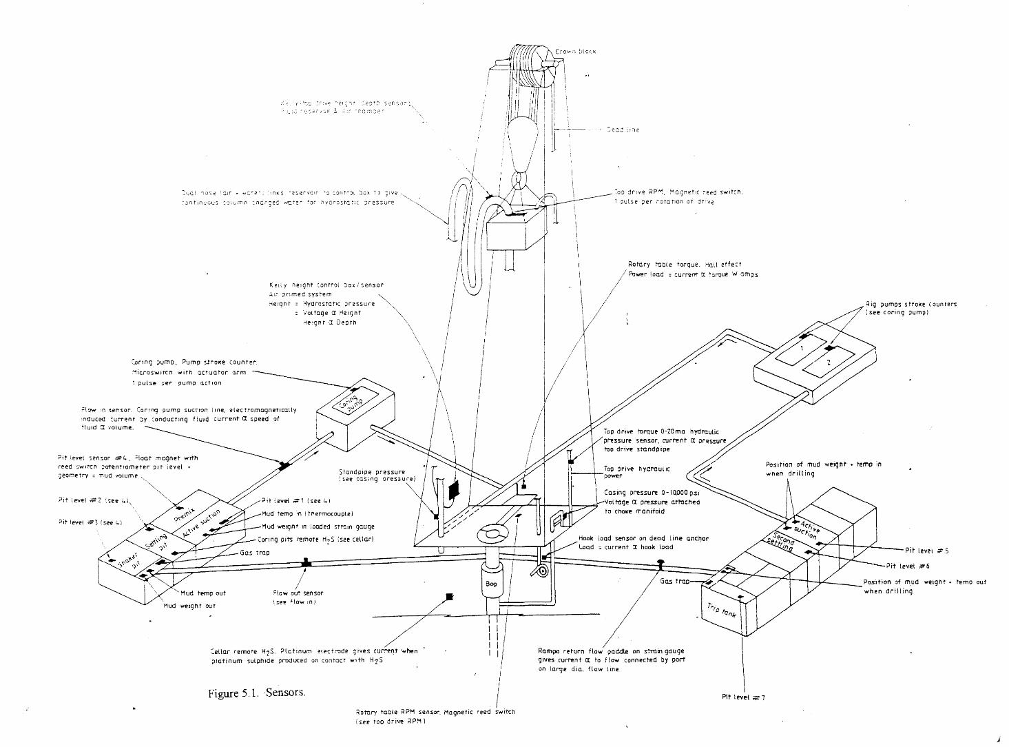
.< ~ I 'f' ~c ~ I~ : '" ~ 0-" e t ~ 1 r ~; e ~ t ~, S ~ n S 0 ~ \
: ~~:~: ~ e ~ 2 i {~,.; I( ~ :..: i""" - no ;--n ~~ e r
Ked y nelglit control box j sensor
:"Ir ;:lnmeCl system :"'erght "'yCrostatlc pressure
vonoqe a Helgnt 1elqnt a Deprh
Coilng pumo, Pump s!rol<e counter,
~icroSY,lIrct'l wITh aouator arm
1 Duls~ per pump a.ct ron
;:low :n '>ensor. Corl~ pump suctIon line, electromagnetically
'n(Juced ~urrent Jy conducting fluId current Il. speed of ftuld a VOlume.
~it level "en~or :':::1." ;Ioat magnet wrth reed $Wlt-cn ;)Ot~nttOml!fer PI t level +
:] earne try :; ,l1ud vOlum e ~
''''', ~,
;J it l eVe1 ;;r, (see 4)
Mud temp 'In I thermocouple)
Mud ~Ignt In loaded STrain gauge
Coring Pits remote H?S (see eeUarl
trap
/ Flow ouT sensor
Mud weIght out (~e~ flo ...... In)
Cellar remote H2S. ?!atinum electrode gives curret1t when platinum sulphide produced on canroct WIth H-ZS
Figure 5.1. ,Sensors,
~otnry table KPM sensOI". Magnetic reed switch
I see too drive ;<PM 1
\ \
I \
~OD drive RP~. Magnetic i'et'd S'Nltch.
1 pulse ;lei ,ota tlOI1 of :lriY~
\ Rotary hlDle torque. Hall effect . \ /~_rload
)/ ; cur~rrt cr. 'Orque W amps
/1
Top drive turque 0-20 ma hydmutjc
pressure sensor, current ex pressure top driv~ standpipe
iop drive hydraulic ~---\-power
Casing preSSUM! 0-10,QOOPSl
Vol tage ex pressure attached to cnoke manifold
load sensor on dead line ancr,or :; current ex hook load
Rampe return flo ..... paddle on strain gauge gives current ex. to flow connected by port on lOl'lje diu. flow line
Pit level #7
Rig pumps 5 troke C oun te~ (see coring pump I
PositiO:1 at mud 'Neight + temp in when drilling
Pit level ;t" 5
Pit level #6
Position of m.ud weight + ~emp out when drilling
Chapter 5 Analysis of The Drilling Results
5.3.2 Hole Opening
Open hole drilling was carried out with tri-cone rock bits in appropriate
assemblies. Hole opening was carried out in stages from 159 mm (6.25 in.)
to 216 mm (8.5 in.) then to 311 mm (12.25 in.) and finally to 445 mm (17.5
in.) as appropriate.
5.3.3 Coring
Continuous core drilling was carried out using the 139.7 mm (5.5 in.) heavy
duty wireline coring system. The procedure for core drilling was that
conventionally used in geotechnical investigation, mineral and coal
exploration industries. Rotation was provided by a hydraulic top drive unit
at rotational speeds up to 220 RPM with corresponding weights on the core
bit of 4000 to 10000 lbs. Core recovery and quality were the main
objectives.
A routine was developed to optimise rig time using additional inner barrels,
all of which were interchangeable within the system, to reduce the non
drilling time and all components of the coring system were carefully
checked as part of the quality system adopted for the project.
Core drilling was interrupted approximately every 50 m to allow testing to
be carried out to determine the environmental pressure measurements
(EPM) in the 50 m interval. This necessitated tripping the coring string and
running a testing assembly on a testing string. Both coring and testing
strings were racked in the rig mast when not in use.
97
ChiipterJ Analysis of The Drilling Resu.lts
5.5 Oilfield Drilling Operation
An oil exploration company for the onshore operations of the National
Petroleum Institute provided drilling data from 10 wells drilled in a field
The Ghani field is located 400 miles to the south east of Tripoli, Libya.
The drilling data were correlated to the depth drilled and classified
according to lithology, mechanical data, and drilling fluid properties. The
records indicated that most of these wells penetrated limestone, shale,
anhydrite, dolmite, and dense limestone. The most common formation
penetrated by these wells are shale and limestone.
The bit mechanical data included size, type, running time, depth in, depth
out, dullness, and nozzle size. Roller cone soft and medium formation bits
were the most common types used for drilling both shales and limestones.
The bit sizes ranged from 8.5 to 26 in., and the maximum depth drilled in
these wells was 10,247 ft.
The bits were graded on a conventional sliding scale from zero (sharp, new)
to eight (completely dull). Each increment indicates one eighth fractional
wear of the teeth.
The mechanical data also included weight on bit and rotary speed. The
weight on bit ranged from 10 to 45 lb for drilling limestone and from 10 to
35 lb for drilling shale. The rotary speed ranged from 30 to 120 RPM for
drilling limestone and from 30 to 80 for drilling shale.
The oil exploration company also provided information on circulation
pressures and rates as well as mud pump dimensions. Rates of penetration
were calculated from bit running time, depth in, and depth out. The
important properties of drilling fluids, such as mud weight, plastic viscosity,
98
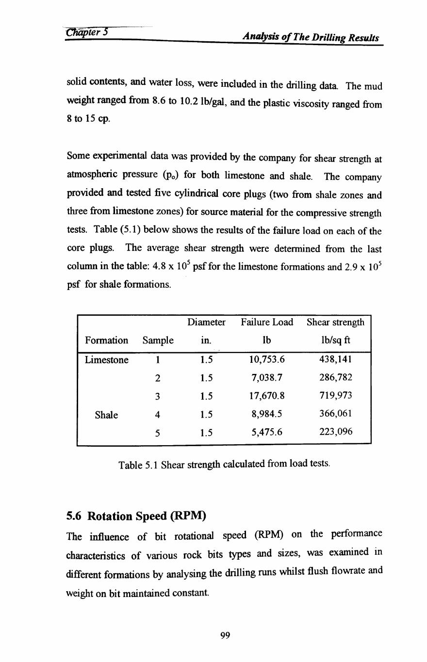
C1iiijJter 5 Analysis of The DriUing Results
solid contents, and water loss, were included in the drilling data. The mud
weight ranged from 8.6 to 10.2 Ib/gal, and the plastic viscosity ranged from
8 to 15 cpo
Some experimental data was provided by the company for shear strength at
atmospheric pressure (Po) for both limestone and shale. The company
provided and tested five cylindrical core plugs (two from shale zones and
three from limestone zones) for source material for the compressive strength
tests. Table (5.1) below shows the results of the failure load on each of the
core plugs. The average shear strength were determined from the last
column in the table: 4.8 x 10⁵ psf for the limestone formations and 2.9 x 10⁵
psf for shale formations.
Diameter Failure Load Shear strength
Formation Sample In. lb lb/sq ft
Limestone 1 1.5 10,753.6 438,141
2 1.5 7,038.7 286,782
3 1.5 17,670.8 719,973
Shale 4 1.5 8,984.5 366,061
5 1.5 5,475.6 223,096
Table 5.1 Shear strength calculated from load tests.
5.6 Rotation Speed (RPM)
The influence of bit rotational speed (RPM) on the performance
characteristics of various rock bits types and sizes, was examined in
different formations by analysing the drilling runs whilst flush flowrate and
weight on bit maintained constant.
99
_. " . €IiJjJter 5 Analysis of The Drilling Results
It should be noted that the author had no influence on the drilling process
by pre-setting the drilling parameters. The drilling data presented are from
actual drilling operations which were being done for the purpose of field
developments and not for the purpose of this investigation.
Normally, by setting the circulation rate, data were then carefully selected
from drilling runs in which all drilling parameters other than rotational
speed were maintained constant. The data points were selected at each
level of rotational speeds during bit runs, the resulting points are presented
in graphical form in Figures 5.2-5.8.
100
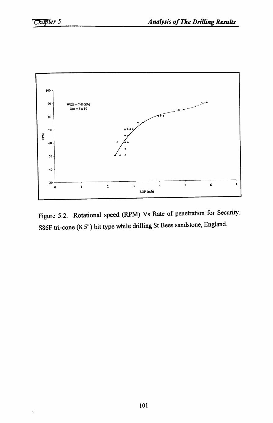
'ChiJPier 5 Analysis of The Drilling Results
100
90 WOB = 7-8 (Idb)
Jets = 3 x 10
80
70
~ 60
SO
40
30
0 2 3 4 6 7
ROP (mIh)
Figure 5.2. Rotational speed (RPM) Vs Rate of penetration for Security,
S86F tri-cone (8.5") bit type while drilling St Bees sandstone, England.
101
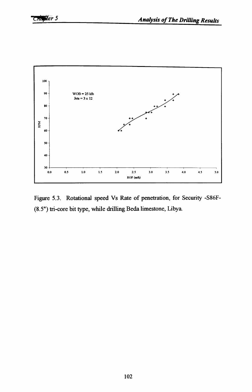
C_er5 Analysis of The Drilling Results
100
90 WOB= 25 ldb Jets = 3 x 12
80
70
~ ~
60
SO
40
30
0.0 O.S 1.0 U 20 2S 3.0 3.S 4.0 4.S s.o ROP (mAl)
Figure 5.3. Rotational speed Vs Rate of penetration, for Security -S86F
(8.5") tri-core bit type, while drilling Beda limestone, Libya
102
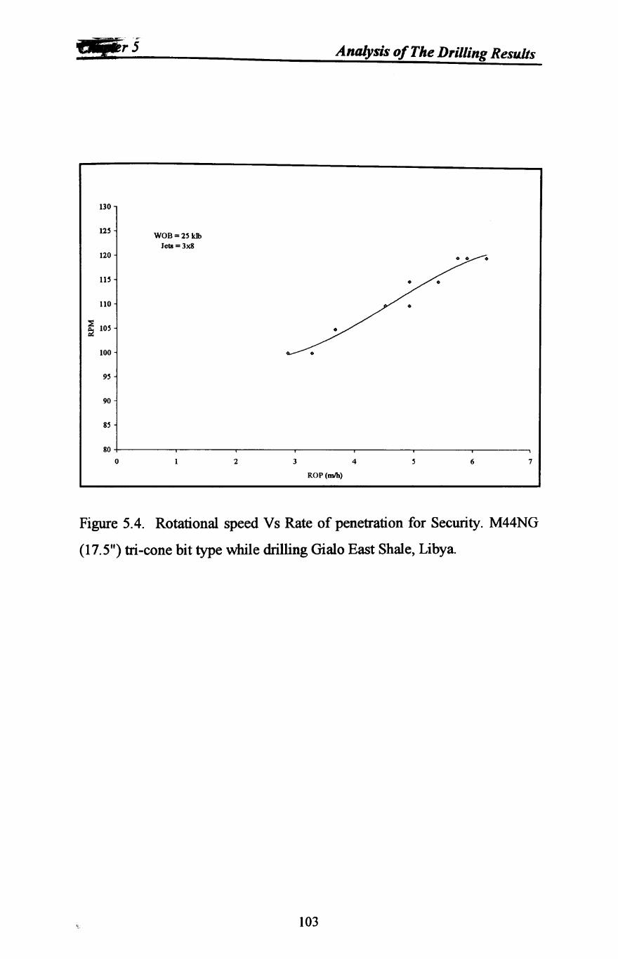
Analysis of The Drilling Results
130
125 WOB=25 kJb
Jets =3x8 120
115
110
~ 105
100
95
90
85
80
0 2 3 4 6 7
ROP(mIh)
Figure 5.4. Rotational speed Vs Rate of penetration for Security. M44NG
(17.5") tri-cone bit type while drilling Gialo East Shale, Libya.
103
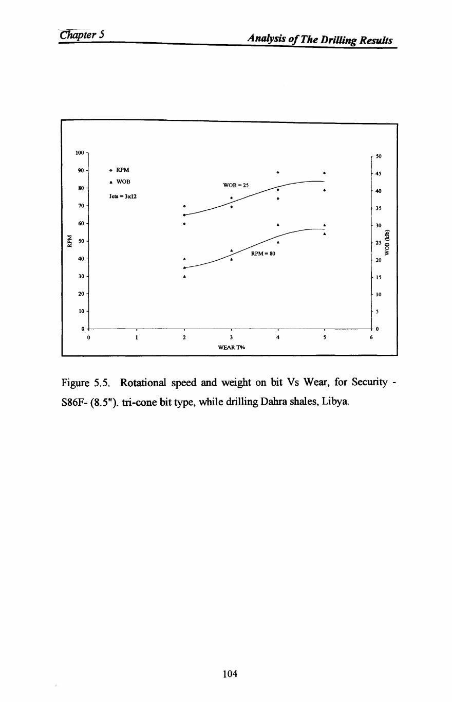
Chapter 5 Analysis of The DriUing Results
100 SO
90 • RPM • • 4S • WOB
80 • 40 Jets =3x12
70 3S
60 • • • 30
~ •
2S ! SO 0 ~
40 20
30 6 IS
20 10
10 S
0 0
0 1 2 3 4 6
WFAR 1"0/0
Figure 5.5. Rotational speed and weight on bit Vs Wear, for Security -
S86F- (8.5"). tri-cone bit type, while drilling Dahra shales, Libya
104
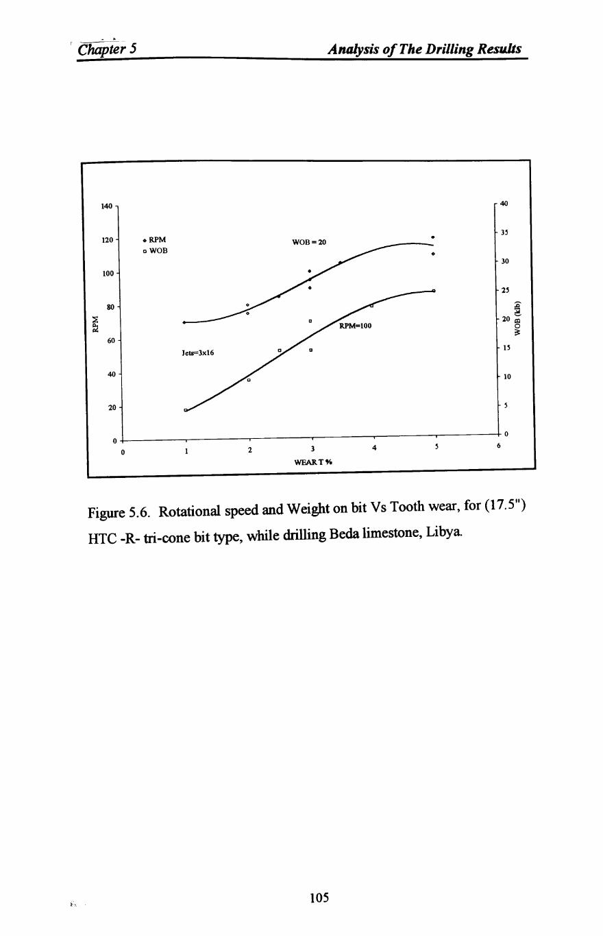
~
Analysis of The Drilling Results
140 40
3~ 120 • RPM • WOB=20
oWOB • 30
100
2~
80 ~ 20 ~
0 ~
60 1~
40 10
20
o+-------~------~------~------~------~-------40 6
o 2 3
WFART%
4
Figure 5.6. Rotational speed and Weight on bit Vs Tooth wear, for (17.5")
HTC -R- tri-cone bit type, while drilling Beda limestone, Libya.
105
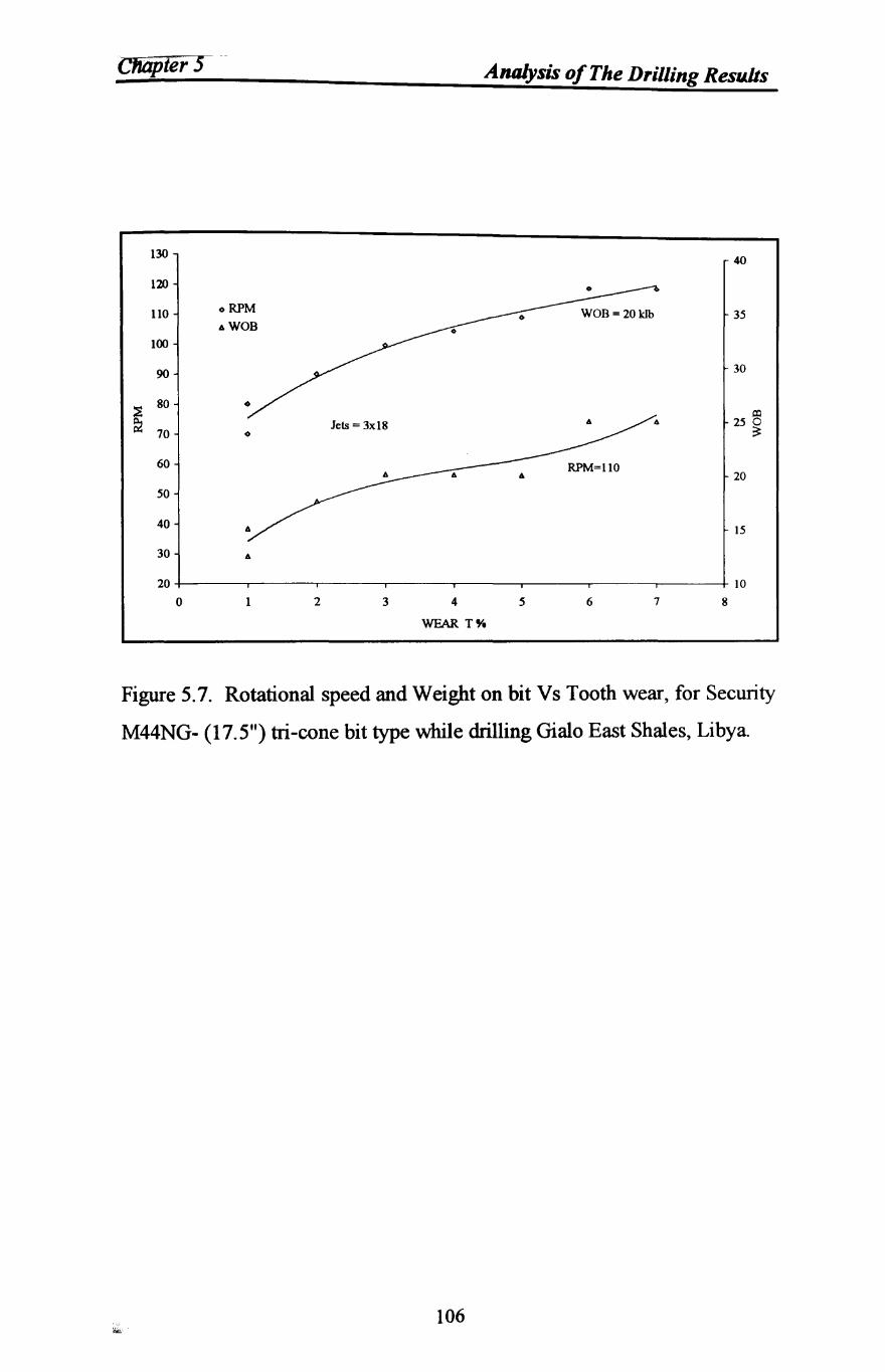
ClfiijJter 5 Analysis of The Drilling Results
130 40
120
llO o RPM 35 AWOB
100
90 30
~ 80
al Jets = 3x18 A 250
70 0 ~
60 RPM=110 20
50
40 15
30 A
20 IO
0 1 2 3 4 5 6 7 8
WEAR T".
Figure 5.7. Rotational speed and Weight on bit Vs Tooth wear, for Security
M44NG- (17.5") tri-cone bit type while drilling Gialo East Shales, Libya.
106
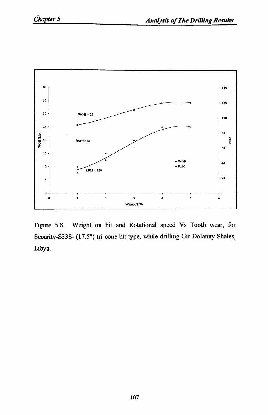
-Chapter 5 Analysis of The Drilling Results
40 140
35 120
30 WOB=25 100
25
:0- 80
: 20 ::s
~ :2
60
15
oWOB 40 10 cRPM
0
5 20
0 0
0 2 3 4 5 6
WEAR To/.
Figure 5.8. Weight on bit and Rotational speed Vs Tooth wear, for
Security-S33S- (17.5") tri-cone bit type, while drilling Gir Dolanny Shales,
Libya
107
Chapter 5 Analysis of The Drilling Results
5.7 Weight On Bit (WOB)
The effect of WOB on the performance characteristics of drilling bits was
examined by analysing the bit runs during which other variables such as bit
types and sizes, formation type, rotational speeds and flushing flowrates
were maintained constant. The graphs of WOB versus ROP from the
drilling runs are shown in Figures 5.9 to 5.20 for six bits which include two
of the same size but different types of core bits and three different sizes and
types of roller cone bits.
Usually, after setting the circulation rate and environmental parameters,
data then were then collected from drilling runs in which rotary speed
(rev/min) was maintained constant and WOB was varied. The data points
were collected at each of these WOB levels, then the resulting scatter in the
data was presented in these figures by the least square fit which yielded a
better fit than the linear fit model. Each figure indicates the bit
manufacturer, size, type, rotation speed, formation and the jet size if
applicable.
108
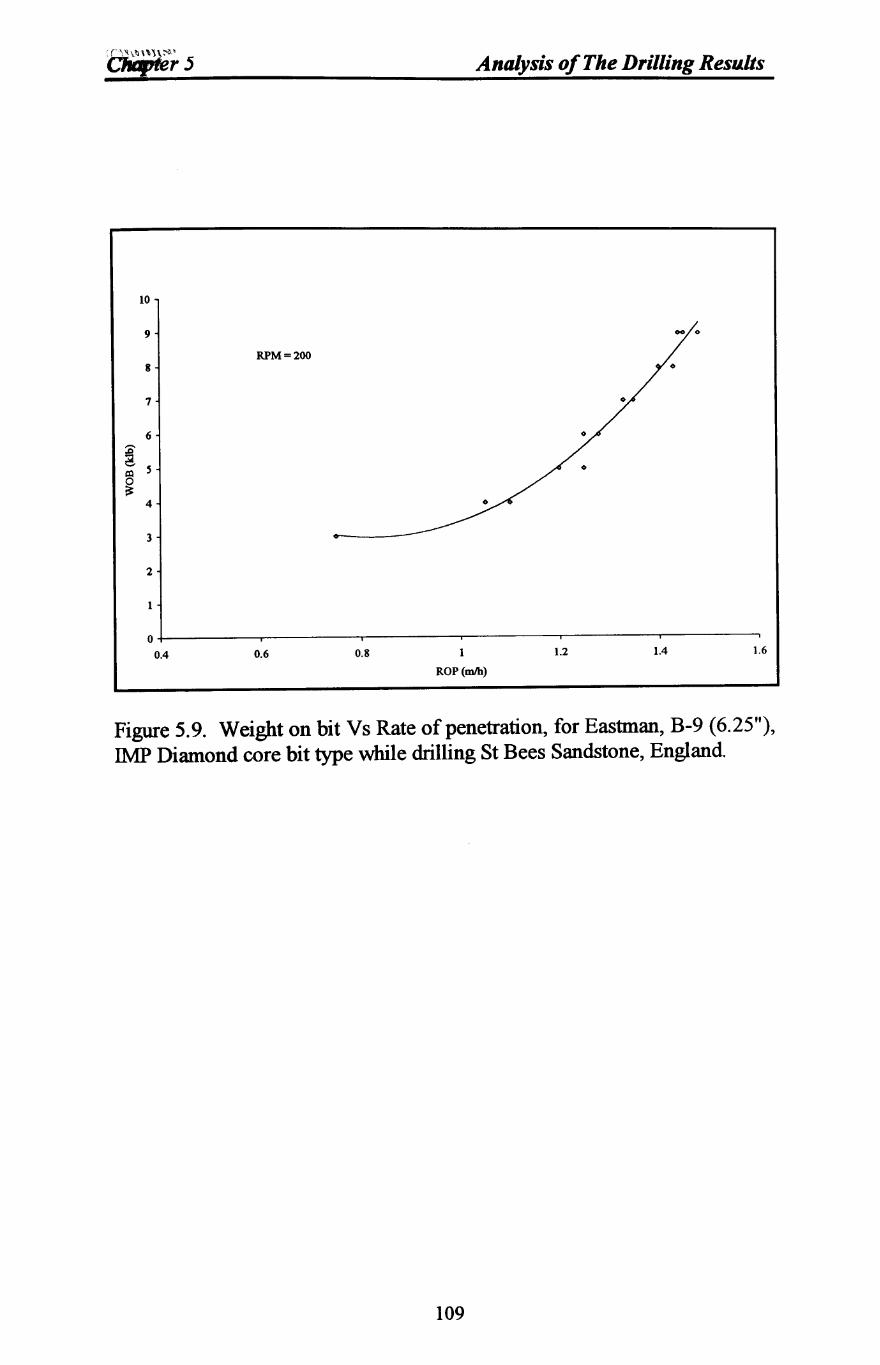
10
9
8
7
6
~ 5 1%1
~ 4
3
2
1
0
RPM = 200
0.4 0.6 0.8
Analysis of The Drilling Resu.lts
1
ROP(mIb)
1.2 1.4 1.6
Figure 5.9. Weight on bit Vs Rate of penetration, for Eastman, B-9 (6.25"), IMP Diamond core bit type while drilling St Bees Sandstone, England.
109
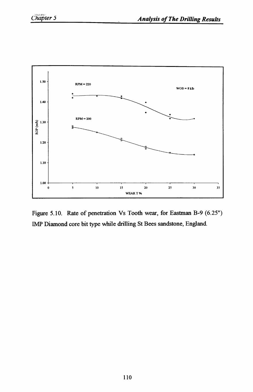
\~,"\\lY'
Chapter 5 Analysis of The Drilling Resu.lts
!.So RPM = 220
WOB= 8klb
o
o
1.40
RPM =200
1.20
1.10
1.00 +--------,-----.-----,------,----,-----,---------, o 10 IS 20 2S 30 3S
WFART%
Figure 5.10. Rate of penetration Vs Tooth wear, for Eastman B-9 (6.25")
IMP Diamond core bit type while drilling St Bees sandstone, England.
110
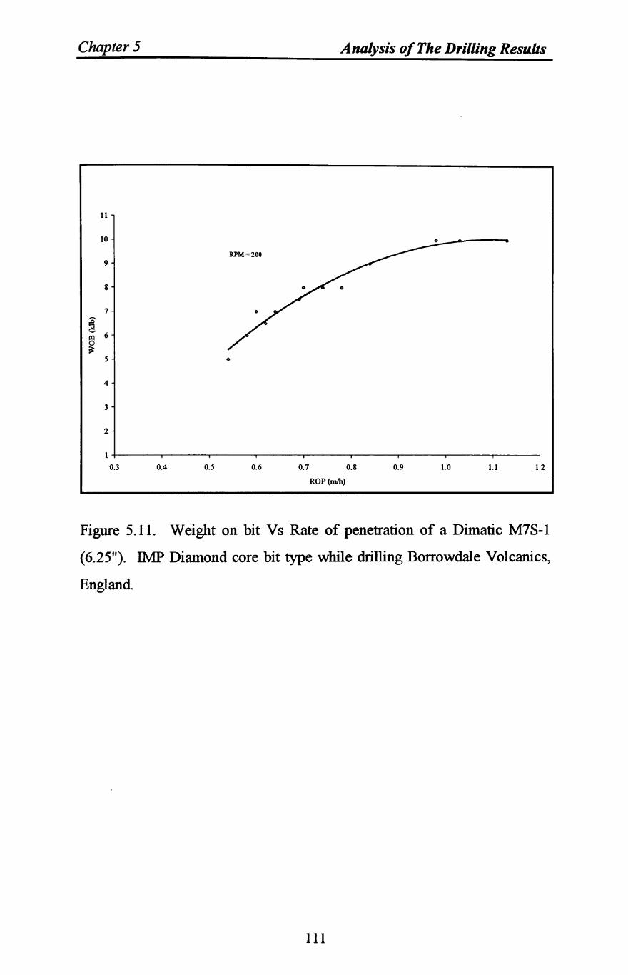
Chapter 5 Analysis of The Drilling Resu.lts
II
10 0
9
8
7
~ 6 ~
0 ~
5 0
4
3
2
1
0.3 0.4 0.5 0.6 0.7 0.8 0.9 1.0 1.1 1.2
ROP(mJh)
Figure 5.11. Weight on bit Vs Rate of penetration of a Dimatic M7S-1
(6.25"). IMP Diamond core bit type while drilling Borrowdale Volcanics,
England.
111
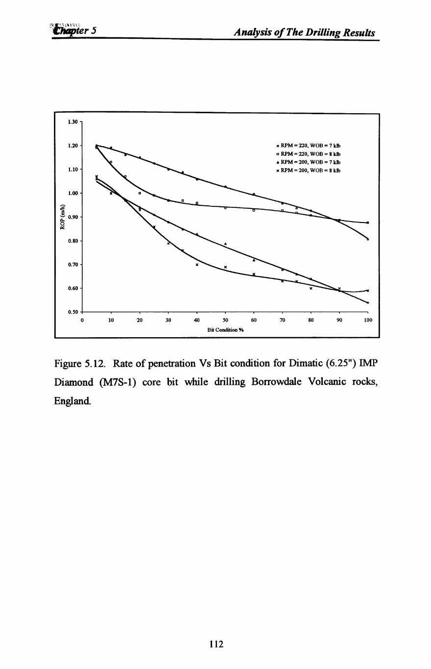
1.30
1.20
1.10
1.00
1: ;;;:- 0.90
~
0.80
0.70
0.60
o.so 0 10 20 30 40
Analysis of The Drilling Results
so 60
Bit Condition'"
o RPM = 220, WOB = 7 kIb
D RPM = 220, WOB = 8 kIb
.. RPM = 200, WOB = 7 kIb
)( RPM = 200, WOB = 8 kIb
70 80 90 100
Figure 5.12. Rate of penetration Vs Bit condition for Dimatic (6.25") IMP
Diamond (M7S-1) core bit while drilling Borrowdale Volcanic rocks,
England
112
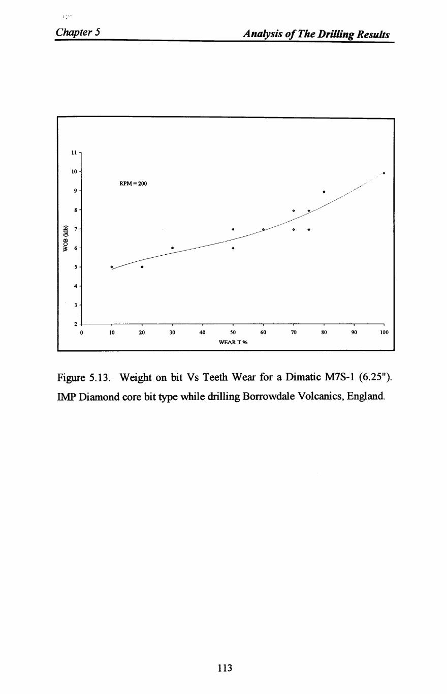
I·:'>
Chapter 5 Analysis of The Drilling Results
11
10
RPM = 200 /
9 0 /
//
8 0 0
~ 7 0 0 0
al
------~ 6 0
S 0
4
3
2 0 10 20 30 40 50 60 70 80 90 100
WFART%
Figure 5.13. Weight on bit Vs Teeth Wear for a Dimatic M7S-1 (6.25").
IMP Diamond core bit type while drilling Borrowdale Volcanics, England.
113
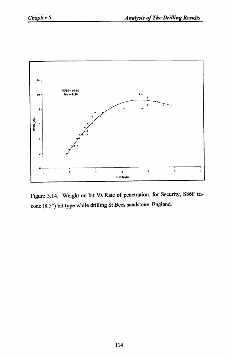
CluiPter 5
12
10
8
4
2
RPM = 60-80 Jets =3xl0
Analysis of The Drilling Results
•• • •
•
O+-------~------~------~--------~------~------~
2 3 4
ROP(mIb)
5 6 7
Figure 5.14. Weight on bit Vs Rate of penetration, for Security, S86F tri
cone (8.5") bit type while drilling St Bees sandstone, England.
114
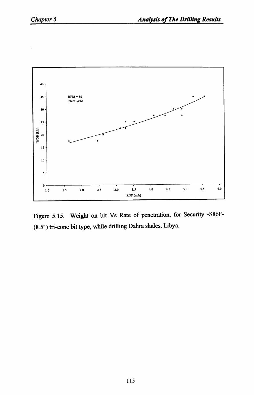
"
Chapter 5 Analysis of The Drilling Results
40
3S RPM = 80 0
Jcta=3xl2
30
0
2S 0
:0-
~ 20
~ 0
IS
10
S
0
1.0 1.5 2.0 2.S 3.0 3.S 4.0 4.S 5.0 5.S 6.0
ROP(mIh)
Figure 5.15. Weight on bit Vs Rate of penetration, for Security -S86F
(8.5") tri-cone bit type, while drilling Dahra shales, Libya.
115

Chapter 5
50
40
30
10
RPM = 80 Jets = 3,,12
o
Analysis of The Drilling Results
o
O~------~------~------~--------~------~------~
o 2 3
WFART%
4 6
Figure 5.16. Weight on bit Vs Wear, for Security -S86F- (8.5") tri-cone bit
type, while drilling Dahra shales, Libya
116
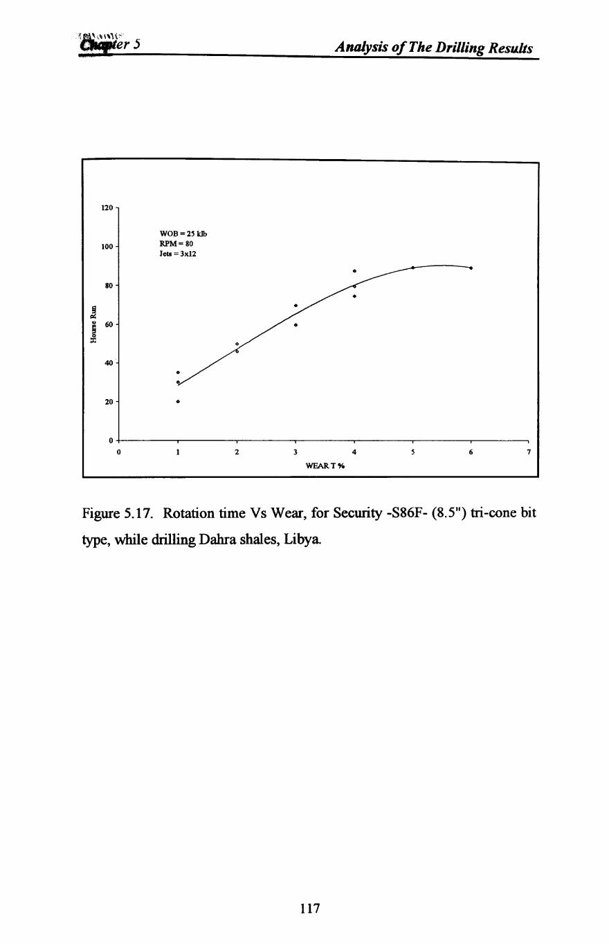
Analysis of The Drilling Resu.lts
120
WOB=2' kIb
100 RPM = 80 lets =3x12
80
! u 60
j 40
20 o
O~----~~----~------~------~------~----~------~
o 2 3 4 6 7
WFART%
Figure 5.17. Rotation time Vs Wear, for Security -S86F- (8.5") tri-cone bit
type, while drilling Dahra shales, Libya
117
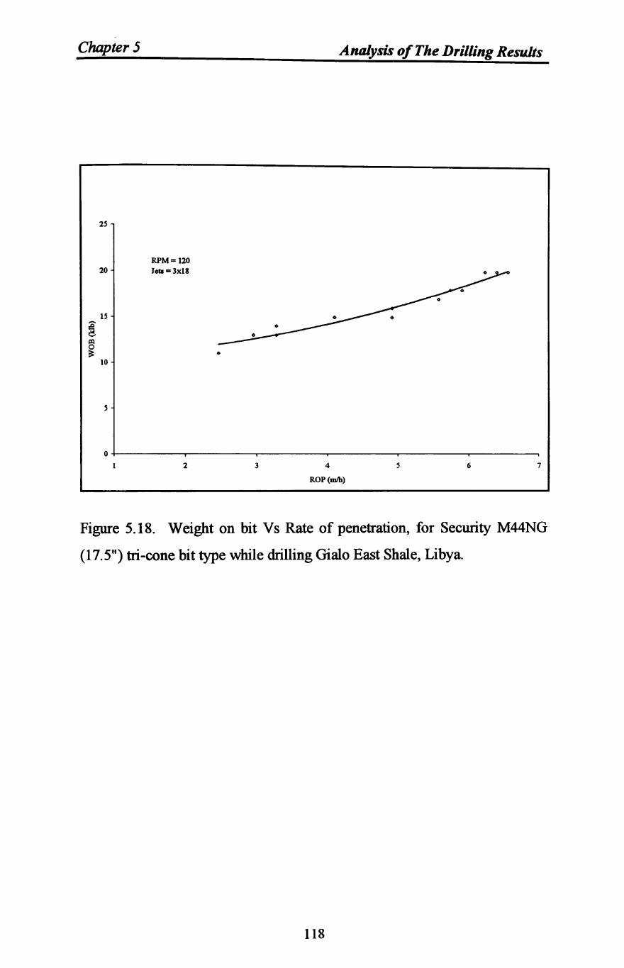
Chapter 5
2S
20
IS
~ ~
10
RPM = 120 Jcta=3xl8
•
Analysis of The Drilling Results
O~------~------~------~------~------~------~
2 3 4
ROP(mIb)
6 7
Figure 5.18. Weight on bit Vs Rate of penetration, for Security M44NG
(17.5") tri-cone bit type while drilling Gialo East Shale, Libya.
118
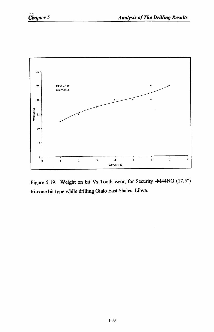
t~""'::J_),
Chapter 5
30
25
20
10
RPM = 110 Jets =3x18
Analysis of The Drilling Results
o
o
o+-----~----~----~----~----~----~----~----~
o 2 3 4
WFART%
6 7 8
Figure 5.19. Weight on bit Vs Tooth wear, for Security -M44NG (17.5")
tri-cone bit type while drilling Gialo East Shales, Libya
119
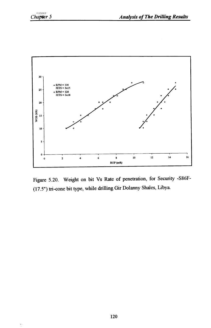
"-'.?_~-.ft,~~_)!l
Chapler 5
30
20
10
• RPM = 100 JEfS=3xlS
o RPM = 120 JEfS= 3x18
Analysis of The Drilling Results
o
o+-----~----~----~~----~----~----~----~----~
o 2 4 6 8
ROP(mIh)
10 12 14 16
Figure 5.20. Weight on bit Vs Rate of penetration, for Security -S86F
(17.5") tri-cone bit type, while drilling Gir Dolanny Shales, Libya.
120
Chapter 5 Analysis of The Drilling Results
5.8 Bit Hydraulics
During the drilling of the shale intervals with the same Security-S86F- 8.5
in bit and with 3x12/32 in-diameter nozzles and while rotary speed was
maintained at 80 RPM throughout, data points were collected In the given
shale interval to ensure comparable rock stress, and by keeping the mud
properties constant and varying hydraulics, through a range of weights on
the bit, data points were taken to examine the effect of hydraulics on the
penetration rate. In the drilling bit industry, hydraulic horsepower hhp
often is expressed in terms of hydraulic horsepower per square inch (hsi) of
projected bit area. Both hhp and hsi are used in this study. Figure 5.21
shows the results of three 12/32 in-diameter nozzles for a range of 5.4 to 6.7
hsi. Also, to investigate the interactive effects of jet horsepower and
crossflow; i.e., flow of fluid across the bit, average rate of penetration was
calculated in different rock types in order to examine their effect. The
findings are illustrated in Figure 5.22 which shows the effect of fluid
flowrate on the penetration rate in various rock types.
A polymer low solid mud was used with properties as follows;
mud type polymer oil-based
weight 8.9lb/gal
marsh viscosity 45-50 sec/qt
plastic viscosity 10 cp
yield point 10-12 Ib/l00 ff API filtration 15-10 cc
pH 9.5
121
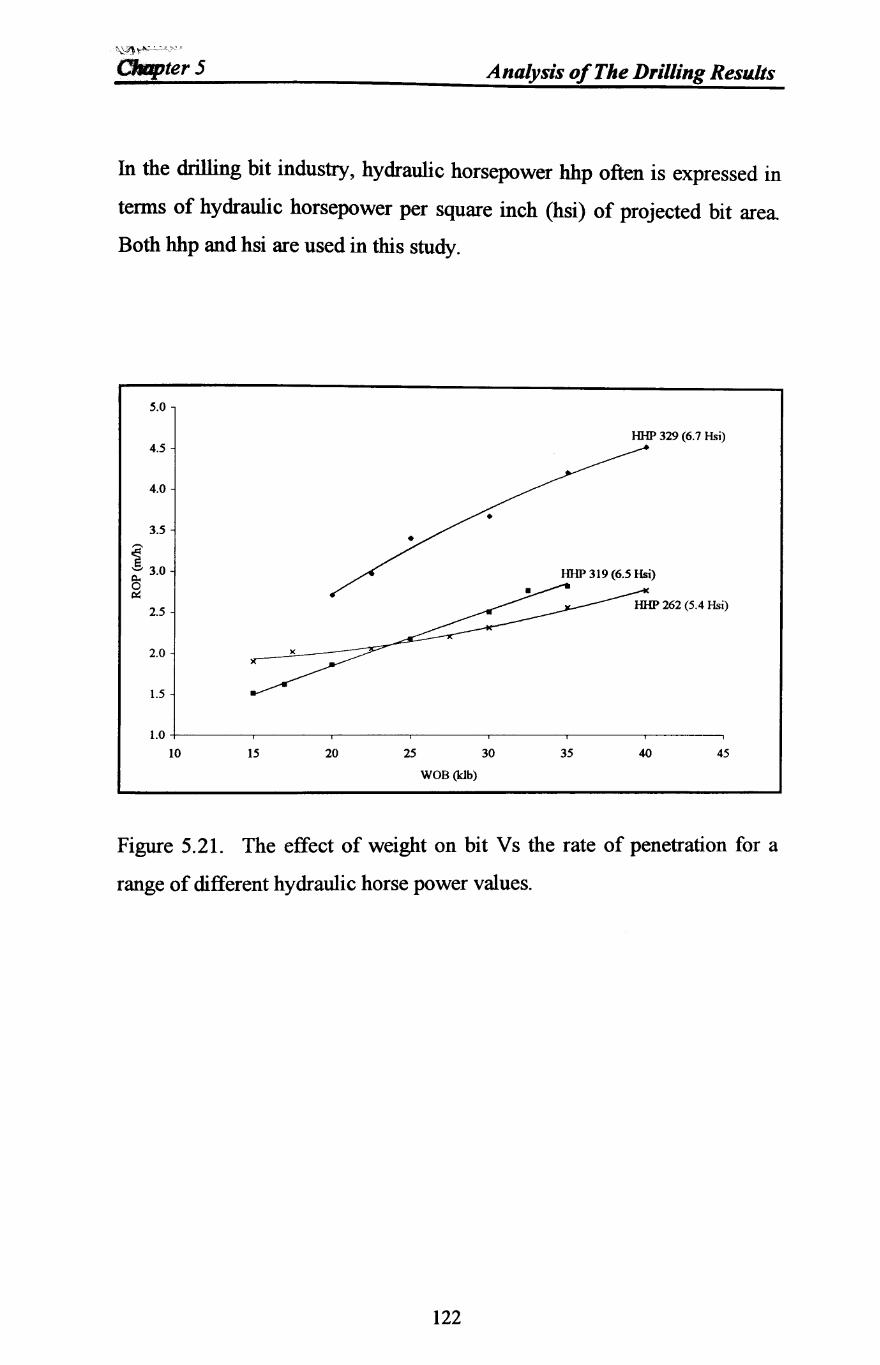
""--\J} r~J("'" " CMpter5 Analysis of The Drilling Resu.lts
In the drilling bit industry, hydraulic horsepower hhp often is expressed in
terms of hydraulic horsepower per square inch (hsi) of projected bit area
Both hhp and hsi are used in this study.
5.0
HHP 329 (6.7 Hsi) 4.5
4.0
HHP 319 (6.5 Hsi)
2.0
1.5
1.0 +-------,--------,-----.---------,--------r----,------,
10 15 20 25 30 35 40 45
WOS (klb)
Figure 5.21. The effect of weight on bit Vs the rate of penetration for a
range of different hydraulic horse power values.
122
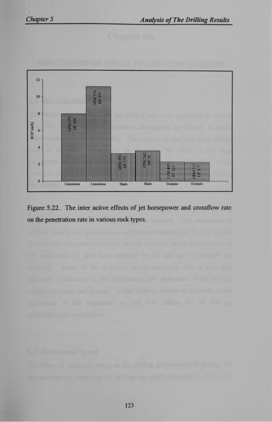
Chapter 5 Analysis of The Drilling Resu.lts
12
10
8
4
2
0+------' Limestone Limestone Shale Shale Dolmite Dolmite
Figure 5.22. The inter active effects of jet horsepower and crossflow rate
on the penetration rate in various rock types.
123
Chapt~r Six
DISCUSSION OF RESULTS AND CONCLUSIONS
6.1 Introduction
The results obtained from all the drilling runs were presented in chapter
five. The data of the main parameters investigated are plotted to enable
determination of their relationship. The purpose of analysing these drilling
runs, as described earlier, was to determine the effect of the main
parameters on drilling rates under field conditions. The effect of the
principal drilling variables on the performance of the bits are described in
this chapter.
An analysis to the highly successful geotechnical investigation drilling
programme, mentioned in chapter fOUf, is included The integration of
oilfield, mining and geotechnical exploration technologies for this special
investigation programme includes several elements which are important in
the application of slim hole methods for oil and gas exploration are
analysed. Many of the technical issues associated with a slim hole
approach is addressed in the development and application of the drilling,
coring equipment and systems. In this chapter, comments are made on the
application of this experience to slim hole drilling for oil and gas
exploration and exploitation.
6.2 Rotational Speed
The effect of rotational speed on the drilling performance of drilling bits
was analysed by examining the drilling run results presented in section 5.6
124
Chapter 6 Discussion of results and Conclusions
and illustrated in Figures 5.2-5.8. It is apparent that the influence, on the
performance characteristics of drilling bits, of perturbing the bit rotational
speed, has a similar form for all the cases investigated The general trend
for all the results, is that an increase in bit rotational speed, produces an
increase in penetration rate.
However, at very high bit rotational speeds, there is often a slight reduction
in the rate of increase of penetration rate with increased bit rotational speed.
The reduction in the rate of increase in penetration rate with increased bit
rotational speed, at high bit rotational speeds, is probably due to there being
such a rapid production of rock fragments that the flush flowrate is
insufficient to effectively remove them from under the bit and hence the bit
is regrinding them.
Considering Figures 5.3 and 5.4, soft formations are generally drilled most
effectively by a combination of deep tooth penetration and a gouging
scrapping action. This action is produced by the equipping of soft
formation bits with relatively long, sharp, widely-spaced cutters affixed to
highly-profiled, offset cones. The appropriate energy levels are obtained
through combinations of relatively lower weights on bit and higher rotary
speeds. These combinations of operating parameters ,were within the
recommended ranges of WOB and RPM set-up by the International
Association of Drilling Contractors (lADC). These recommendations set the
upper and lower limits which were observed The trade-off between WOB
and RPM were kept in mind when using these recommendations. This good
drilling practice entailed the selection of the appropriate WOB and RPM,
which resulted the most economical combination of penetration rate and
acceptable bit life as illustrated in Figures 5.5 to 5.8. The bit life is
presented in wear % form of bit life remaining. The bits were graded on a
125
Chapter 6 Discussion of results and Conclusions
conventional sliding scale from zero (sharp, new) to eight (completely dull).
Drilling at very low WOB and low RPM levels was avoided to prevent the
sliding action which produces unnecessarily low penetration rates. Also,
operating at high WOB and high RPM was avoided which produces
unnecessarily accelerated wear. Both combinations are uneconomical.
This field investigation of drilling rotary speeds confirms the
comprehensive laboratory study by Ambrose, 1987, Ersoy, 1995, Shah,
1992, Rowsell, 1991 and Waller, 1992, which indicated to the effect of bit
rotational speed on the rate of penetration.
6.3 Weight On Bit
The effect of WOB on the performance characteristics of drill bits was
examined by analysing the bit runs through which the rotational speed and
flushing fiowrate were maintained constant. The graphs of WOB versus
ROP from the drilling runs are shown in Figures 5.9 to 5.20 for six bits
which include two of the same size but different core bits and three
different sizes and types of roller cone bits.
The general trend of all the results, is that initially increasing values WOB
produces a rapid increase in penetration rate. Then a linear curve is
observed in the majority of the result graphs at moderate bit weights.
Initially, when low bit weight is used, drilling rate and footage per bit will
be very low. The reason is that drilling or making hole will be achieved
only by a scraping action of the bit teeth or indenters. In this type of action,
the teeth are worn off rapidly, and very little progress is made. This type of
result often occur where operators are forced to reduce bit weight in hard
formations because of crooked-hole problems and/or as a method of
126
Chapter 6 Discussion of results and Conclusions
alleviating the problem of drill-pipe fatigue resulting from drill-stritlg
oscillation and vibration related to both high bit weights and rotational
speed Another reason where drilling rate is not directly proportional to bit
weight is the lack of efficient cleaning below the bit and formation chips are
being reground However, increasing the WOB further tends to decrease
the rate of increase in ROP in some drilling runs, noted in Figures 5.11 and
5.14. This type of behaviour often is called bit "floundering". The poor
response of penetration rate at high values of bit weight is usually attributed
to less efficient bottom hole cleaning at higher rates of cuttings generation
or to a complete penetration of the cutting element into the hole bottom.
The nature and form of the penetration rate and wear characteristic of the
impregnated core bits in the medium hard St Bees sandstone and the
abrasive volcanic formations Figures 5.9-5.13 can be explained by
considering their drilling process.
At low bit loads, the diamond indenters in the core bit do not penetrate the
rock and when the core bit is rotated, they simply "skid" across the rock
surface which produces a small amount of rock fragments, which results in
a low penetration rate.
With an increase in the weight on bit, the point is reached when the
diamond indenters in the core bit begin to penetrate the rock and when the
core bit is rotated, rock fragments are produced As the WOB is increased
from this point, the depth of diamond indenter penetration is also increased
and therefore there is an increase in penetration rate. During this phase of
the drilling process, the diamond indenters are still subjected to wear when
the core bit is rotated The amount of wear occurring, per unit linear
distance traversed by the diamond indenters, will now be slightly greater
127
Chapter 6 Discussion of results and Conclusions
than at lower WOB, due to there being more rock fragments but, because of
the increase in penetration rate, there is a net reduction in wear per meter
drilled as the diamond indenters traverse a shorter linear distance for a
given distance drilled.
When the WOB is further increased, the point is reached where the full
diamond indenter protrusion is embedded in the rock and no greater amount
of rock fragmentation can occur. Hence the maximum penetration rate is
achieved Any further increase in WOB above that required to produce this
maximum penetration rate, can cause no greater amount of rock
fragmentation and indeed may cause a reduction in the rate of increase of
penetration rate, as is seen in Figure 5.11.
The increase in wear rate from its tnlmmum level, even though the
penetration rate is still increasing, is caused by the increased matrix
abrasion and increased diamond wear and degradation. Increased matrix
abrasion at higher WOB, could be due to the liberated rock fragments being
more numerous and more restricted in their passage over the core bit face,
or from the intact rock itself when at full diamond indenter penetration.
Support of this hypotheses can be drawn from the minimum wear rate
occurring at a slightly lower WOB than the maximum penetration rate in the
drilling runs performed
The increased bit wear rate at higher WOB is possibly caused by the greater
force being applied to each individual diamond indenter. This increases its
wear rate and also makes it more prone to breaking up and being lost. The
difference in the magnitudes of penetration rates and wear rates and the
WOBs at which these effects occur is due to variation in bit design and type
and the physical properties of the rocks being drilled
128
Chapter 6 Discussion o/results and Conclusions
6.4 Bit Hydraulics
It is apparent from observations and by analysing Figure 5.20 that smaller
jet nozzles clearly effect the rate of penetration. The results indicate that
smaller nozzle diameters provide higher jet velocities which are needed to
clean loose chips from the hole between tooth impacts and help dislodge
chips that are held in place by differential pressure. The primary cause of
this effect is a higher turbulence levels at the jet boundary caused by a
higher jet velocity obtainable by the smaller nozzle diameters. Smaller
nozzles can deliver more hydraulic energy to the bottom of the hole more
efficiently than larger nozzles. Also there is a destructive interference
between the jets issuing from the nozzles and the fluid returning from under
the bit.
The parameters most commonly used to quantify the effect of hydraulics is
the jet impact force at the bit. The optimum bit hydraulics conditions are
considered to be those which gave maximum impact force at the bit while
keeping the annular velocity within limits established by the borehole
erosion and cuttings transport conditions.
This study of field investigation confirm the comprehensive laboratory
study published by Winter and Warren, 1986, which indicated to the effect
of bit hydraulics on the rate of penetration and concluded that ROP is a
function of nozzle diameters.
Figure 5.22. shows the interactive effects of jet horsepower and crossflow,
i.e., flow of fluid across the bit on 12 1/4 in. soft and hard formation bits,
which are the correct type of bits for the particular formations being drilled.
The soft formation bit has drilled (7.97 m/h) with 366 jet horsepower (hp)
129
Chapter 6 Discussion o/results and Conclusions
and flow rate of 570 gpm. Increasing the jet hp by 19 % to 437 hp, has
increased the drilling rate by 37% to (11 19 m/h).
The conclusion is that this bit was not drilling its potential because the teeth
were not being cleaned. The penetration rate of this bit could not increase
significantly with higher weights or rotary speeds at the low jet horsepower,
but at higher jet horsepower, additional weights on bit and rotary speed,
would cause this bit to drill quite effectively. A minor increase in operating
cost for the hydraulics can yield a major reduction in overall cost in soft to
medium hard formations.
Also, the penetration rate of the hard Dolmite formation bit was not affected
when the flow rate and jet horsepower were increased. This insensitivity is
probably due both to low jet velocity and to the interference effect of the
high flowrate around the short teeth.
6.5 Core Bit Design and Performance at Sellafield and
Dounreay
In the Sellafield's investigative core drilling, the initial design of core bits
was based on the anticipated geology and previous experience in similar
formations. The only data available was from general geological
descriptions so it was necessary to carry out some experimentation in the
initial holes. At Sellafield, the sandstones were more accommodating to a
range of bit settings and profiles, but at Dounreay, the strong crystalline
rocks posed the usual problems of bit type and achieving an acceptable
trade off between penetration rate and bit life. In this initial borehole, the
130
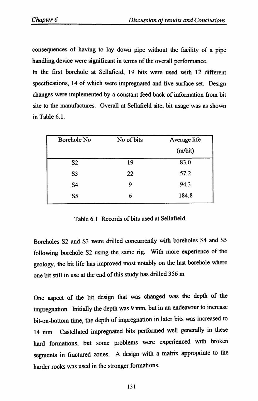
Chapter 6 Discussion of results and Conclusions
consequences of having to lay down pipe without the facility of a pipe
handling device were significant in terms of the overall performance.
In the first borehole at Sellafield, 19 bits were used with 12 different
specifications, 14 of which were impregnated and five surface set. Design
changes were implemented by a constant feed back of information from bit
site to the manufactures. Overall at Sellafield site, bit usage was as shown
in Table 6.1.
Borehole No No of bits Average life
(mlbit)
S2 19 83.0
S3 22 57.2
S4 9 94.3
S5 6 184.8
Table 6.1 Records of bits used at Sellafield
Boreholes S2 and S3 were drilled concurrently with boreholes S4 and S5
following borehole S2 using the same rig. With more experience of the
geology, the bit life has improved most notably on the last borehole where
one bit still in use at the end of this study has drilled 356 m.
One aspect of the bit design that was changed was the depth of the
impregnation. Initially the depth was 9 mm, but in an endeavour to increase
bit-on-bottom time, the depth of impregnation in later bits was increased to
14 mm. Castellated impregnated bits performed well generally in these
hard formations, but some problems were experienced with broken
segments in fractured zones. A design with a matrix appropriate to the
harder rocks was used in the stronger formations.
131
Chapter 6 Discussion of results and Conclusions
Some points from the drilling experience to date include:
• Impregnated bits were used in favour of surface set bits in the Permo
Triassic formations as higher rates of penetration were achieved
• Poor performance of surface set bits was experienced in the Borrowdale
volcanics.
• Gauge reinforcement by increasing the diamond concentration and
increasing the number of tungsten carbide inserts increased bit life
significantly.
• Pump pressure fluctuations maintained the waterway size by preventing
the possibility of a build up of fines or slithers of rock jamming the
watenvays.
• In the harder, fine grained formation, the inclusion of silica in the matrix
formation improved the self sharpening characteristics to maintain
penetration rates at an acceptable level over a sustained period.
• A further measure to increase the self sharpening characteristic was to
lower the density of the matrix at the sintering stage which improved the
performance in the more silicfied, fine grained materials.
Some experimentation has been carried out with PDC bits in the Permo
Triassic sandstones, but some oscillation in torque and' associated string
vibration effects were experienced Typically, penetration rates at
Sellafield during coring ranged from 0.7 mIhr to 3.0 mIhr with an average of
about 1.6 mIhr.
At Dounreay, surface set bits performed reasonably well in the interbedded
siltstones and sandstones of the Devonian sequence. The majority of bits
used through the Moinian series were impregnated and a preference for
132
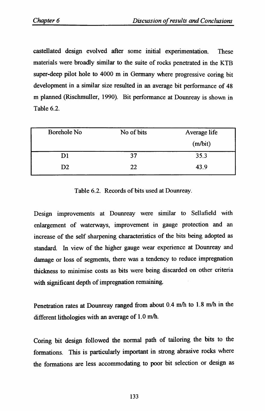
Chapter 6 Discussion ofresults and Conclusions
castellated design evolved after some initial experimentation. These
materials were broadly similar to the suite of rocks penetrated in the KTB
super-deep pilot hole to 4000 m in Germany where progressive coring bit
development in a similar size resulted in an average bit performance of 48
m planned (Rischmuller, 1990). Bit performance at Dounreay is shown in
Table 6.2.
Borehole No
Dl
D2
No of bits
37
22
Average life
(mIbit)
35.3
43.9
Table 6.2. Records of bits used at Dounreay.
Design improvements at Dounreay were similar to Sellafield with
enlargement of waterways, improvement in gauge protection and an
increase of the self sharpening characteristics of the bits being adopted as
standard In view of the higher gauge wear experience at Dounreay and
damage or loss of segments, there was a tendency to reduce impregnation
thickness to minimise costs as bits were being discarded on other criteria
with significant depth of impregnation remaining.
Penetration rates at Dounreay ranged from about 0.4 mIh to 1.8 mIh in the
different lithologies with an average of 1.0 mIh.
Coring bit design followed the normal path of tailoring the bits to the
formations. This is particularly important in strong abrasive rocks where
the formations are less accommodating to poor bit selection or design as
133
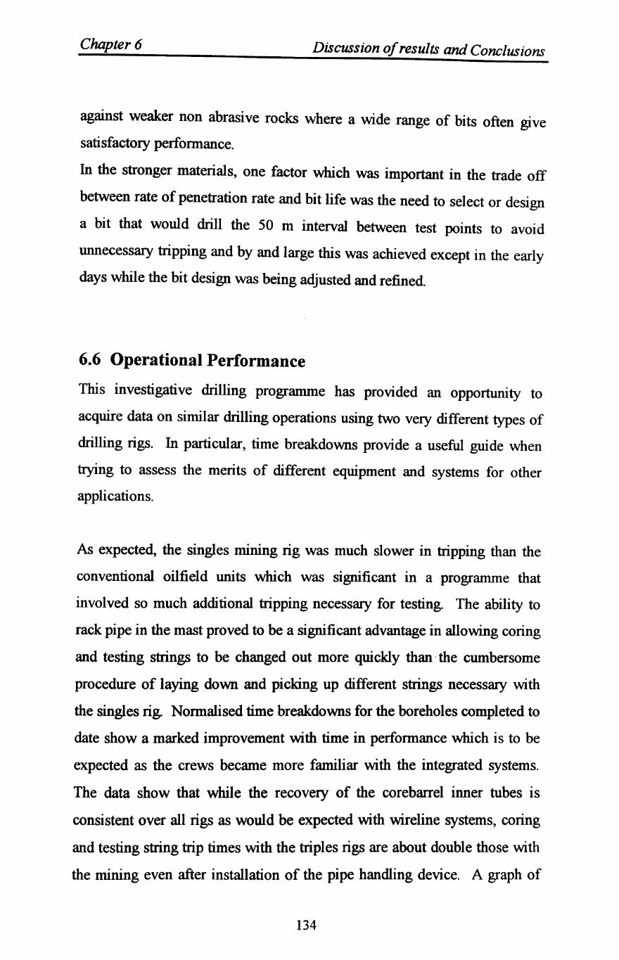
Chapter 6 Discussion of results and Conclusions
against weaker non abrasive rocks where a wide range of bits often give
satisfactory performance.
In the stronger materials, one factor which was important in the trade off
between rate of penetration rate and bit life was the need to select or design
a bit that would drill the 50 m interval between test points to avoid
unnecessary tripping and by and large this was achieved except in the early
days while the bit design was being adjusted and refined.
6.6 Operational Performance
This investigative drilling programme has provided an opportunity to
acquire data on similar drilling operations using two very different types of
drilling rigs. In particular, time breakdowns provide a useful guide when
trying to assess the merits of different equipment and systems for other
applications.
As expected, the singles mining rig was much slower in tripping than the
conventional oilfield units which was significant in a programme that
involved so much additional tripping necessary for testing. The ability to
rack pipe in the mast proved to be a significant advantage in allowing coring
and testing strings to be changed out more quickly than' the cumbersome
procedure of laying down and picking up different strings necessary with
the singles rig. Normalised time breakdowns for the boreholes completed to
date show a marked improvement with time in performance which is to be
expected as the crews became more familiar with the integrated systems.
The data show that while the recovery of the corebarrel inner tubes is
consistent over all rigs as would be expected with wireline systems, coring
and testing string trip times with the triples rigs are about double those with
the mining even after installation of the pipe handling device. A graph of
134
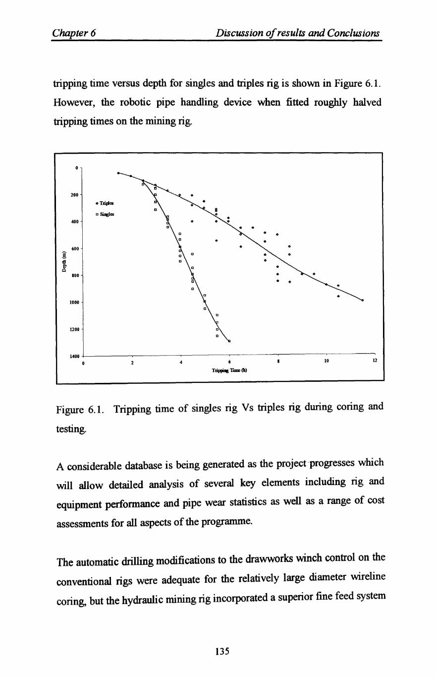
Chapter 6 Discussion of results and Conclusions
tripping time versus depth for singles and triples rig is shown in Figure 6.1.
However, the robotic pipe handling device when fitted roughly halved
tripping times on the mining rig.
~ ~ Q
o
200
oT~es
D~es
400
0
600 0
0
100
1000
1200
1400 +-----~------,--------,-------.------.-------,
o 2 4 6
Trippag TIIIII (h) • 10 12
Figure 6.1. Tripping time of singles rig V s triples rig during coring and
testing.
A considerable database is being generated as the project'progresses which
will allow detailed analysis of several key elements including rig and
equipment perfonnance and pipe wear statistics as well as a range of cost
assessments for all aspects of the programme.
The automatic drilling modifications to the drawworks winch control on the
conventional rigs were adequate for the relatively large diameter wireline
coring, but the hydraulic mining rig incorporated a superior fine feed system
135

Chapter 6 Discussion of results and Conclusions
which was more suitable for coring. For smaller diameters where bit weight
control is more sensitive, the mining rig approach is desirable.
136
Chapt~r S~v~n
CONCLUSIONS AND RECOMMENDATIONS
7.1 Conclusions
The effects of the operating parameters on the perfonnance of the bits in
field drilling were examined. The relationship of the operating parameters
with each other were also detennined. Increasing WOB gave an increase in
ROP up to some yielding point, at which, the rate of increase in ROP was at
a lesser rate. The results have also shown that ROP increase with RPM.
The interactive effects of jet horsepower and fluid flow across the bit was
detennined and illustrated.
The findings of this field investigation of drilling parameters confinn the
comprehensive laboratory study by previous investigations which indicated
to the effect of these operating parameters on the drilling perfonnance.
An analysis of a highly successful geotechnical investigation drilling
programme has been presented. This project has given an opportunity to
evaluate the advantages and disadvantages, merits and limitations of
applying different drilling and associated technologies for deep hole
construction to safely and routinely provide high quality geoscientific
information. Several elements are included in this special investigation
drilling programme, which are important to the application of slim hole
methods for the oil and gas industry and gives some confidence that with
the right approach there are benefits to be realised in an integrated
technology approach. Many of the technical issues associated with a slim
hole approach were addressed.
137
Chapter 7 Conclusions and Recommendations
In the search for ways to reduce costs in exploration and exploitation of oil
and gas resources, currently there is renewed interest in 'slim hole' and
'ultra slim hole' methods. The term 'slim hole' is widely used to refer to a
range of drilling applications ranging from a small size conventional rotary
drilling approach using destructive bits to small diameter high speed coring
systems similar to those used in deep mining exploration where depths up to
5000 m have been achieved In the case mentioned in chapter four , the
final hole diameter is relatively large and more consistent with the smaller
range of normal drilling, but the use of a wireline coring as a means of
advancing a hole and providing high quality data addresses many of the
issues which are currently under debate by the various groups working in
this field.
The objective in applying slim hole methods to oil and gas exploration is
principally to reduce cost, but there is also a secondary potential benefit in
areas where geological control data is not available provided by the option
to continuous core at a lower cost penalty than with conventional oilfield
exploration methods.
Experience of slim and ultra-slim hole drilling for oilfield applications has
been of mixed success with problems of mixing mining and oilfield
cultures. Despite the reduced scale of the operation realising real costs
savings has not always been achieved
The experience at Sellafield has highlighted several facts of the application
of wireline coring and small mining rigs which provides additional
information in considering these methods for other uses.
138
Chapter 7 Conclusions and Recommendations
Small rigs can be constructed that have the capability for considerable depth
using small, lightweight strings providing that they are designed to provide
the flexibility required to cope with both surface hole drilling in sizes up to
say 445 mm (17.5 in.) even 508 mm (20 in.) and small diameter high
rotational speed wireline coring systems with hole sizes down to 76 mm (3
in.) or even smaller for the lower sections of the hole.
Small rigs such as the mining units obviously occupy much smaller sites
than the conventional rigs and hence there are savings in site preparation
costs, although these can be insignificant if there are long access roads to
construct.
Mobilisation costs with the small rigs are much reduced which is
particularly important in remote location operations. Fast moving or heli
transportable units with the reduced costs of supporting consumables,
materials and equipment provide the best potential for significant savings
with this approach. Crews are reduced with obvious savings on costs as
well as accommodation and travel expenses. The mining approach is more
conducive to an integrated service philosophy with associated cost benefits.
Wireline coring In the smaller sizes can out perform small diameter
destructive drilling in certain formations providing the drilling system
allows the optimum parameters to be adopted Wireline coring systems can
be advantageous where formation problems occur and it is possible to leave
the coring string in place as a permanent casing and drill through the string
with a smaller size to continue the hole. However, some concerns remain
and must be seriously addressed before the benefits of the mining approach
can be translated into real savings for oil and gas exploration and
exploitation.
139
Chapter 7 Conclusions and Recommendations
Singles rigs are slow in tripping especially where the pipe cannot be racked
in the mast even with pipe handling devices to assist and unless drilling
with few bit trips or limited testing is anticipated, tripping costs will become
significant. Pipe handling generally needs careful thought to optimise rig
time and where possible introduction of another process such as the use of
lift plugs should be avoided.
The various programmes already undertaken and currently being considered
under the umbrella of 'slim hole' drilling use several different types of
strings for both coring and drilling. So far there is no consistency in this
area and it can be seen that there are many considerations and trade offs.
Open hole drilling in small sizes is often slow. Continuous coring dictates a
weaker pipe than can be successfully used for destructive drilling and the
problems of well control become more acute especially in the smaller sizes.
Wireline coring strings are more like casing and hence have limitations on
burst strengths even assuming the connections are in ideal condition so
limiting their use in highly pressured formations.
Small diameter systems provide less potential for successful fishing, indeed
wireline coring pipe can only be fished with spears. The mining industry
accepts hole failures and routinely side-tracks if strings are lost, but better
quality control, preventative inspection and improved well planning and
drilling procedures should reduce the risk of failure.
Kick detection and procedures will remal.n a key issue. The use of
electromagnetic flowmeters is a useful method in detection, although these
devices have not been extensively tested in the application reported in this
thesis with a high particulate content in the mud stream which may be the
case with small diameter destructive drilling.
140
Chapter 7 Conclusions and Recommendations
7.2 Recommendations
What is needed is a comprehensive review of all pipe t)pes available and
safe operating limits established and presented in a consistent format. Pipe
lengths also vary and this needs to be standardised to give a range of
options which can be easily accommodated without changes to the rigs or
the rigs configured so that they can accept different pipe lengths.
Well control methods need to be investigated more thoroughly and
procedures adopted to suit the special cases which slim hole applications
present.
The approach of integrating the tlowmeters with the mud logging unit
points to one of the key areas which needs to be developed if slim hole
drilling is to become a useful cost effective method of exploration. The
mud logging data, drilling parameter monitoring and kick detection and
control and all other instrumentation and data acquisition should be
concentrated in one unit or service and the appropriate data made available
to the driller and crew on displays using the latest information technolog)
S)stems. There is no merit in duplicating S)stems on the rig which only
adds cost. Providing the information service is manned by competent
personnel, this would be a discreet package within the integrated drilling
system providing reliable data manned by specialists. This is especially
true if the full benefit of reduced rig crews is to be realised Rigs could
include the data acquisition sensors built into the architecture with
permanent wiring to a data connection box for simple hook ups on moves.
This approach lends itself to the introduction of automation and eventually
artificial intelligence systems. In this connection, automatic drilling
141
Chapter 7 Conclusions and Recommendations
equipment and drawworks design must include comprehensive control
systems independent of the braking systems.
Quality management and time efficiency must be a main feature of the
application of slim hole methods to the oilfield by developing routine
procedures which ensure problem free drilling and safe operations. By
using both adapted oilfield equipment and heavy mining equipment for the
same drilling programmes, the merits of each approach can be seen. It
would appear that if slim hole concepts are to become a mainstream activity
in the oil and gas industry, purpose built rigs with the flexibility to cope
with the range of options available are necessary as retrofitting the
architecture of a new culture or adapting existing equipment is not ideal if
the real benefits of this approach are to be realised
142

References
143
REFERENCES
A1-ameen, S. I, Talks, M. G., Waller, M. D., Tolley, F. P., Moreton, G.,
Lomas, M. A. and Y ardley, E. D., 1992, The prediction and reduction of
abrasive wear in mining equipment. Final report on ECSC research project
No. 7220-AE/821, University of Nottingham and British Coal TSRE,
Bretby.
Ambrose, D., 1987, Diamond core bit performance analysis. Unpublished
Ph.D. thesis, University of Nottingham.
Ashton, S. M., 1984, Slim hole drilling in the Canning basin: Philosophy
and application, Geological Society of Australia, Perth. pp. 521-531.
Atkins, B. C., 1983, The utilization and catagorisation of manufactured
diamond materials within the mining inddustry of western Europe,
Geodrilling, February.
Barr, M. V. and Brown, E. T., 1983, A site exploration trial USIng
instrumented horizontal drilling. 5th Congress of International Society for
Rock Mechanics, Melbourne, Australia
Black, A. D., 1977, Drillability of sandstone and dolDrite at simulated
depth, ASME Petroleum Division Conference, Houston, September, pp. 8-
22.
Bode, D. J. Noffke, R. B. and Nickens, H. V., 1989, Well control methods
and practices in small diameter wellbores, SPE 19526, Annual Technical
conference and exhibition, San Antonio, Tex, 8-11 October.
144
REFERENCES
Bourgoyne, A. T. Jr. Millheim, K. K. Cheneverert, M. E. and Young, F.
S. Jr., 1986, Applied drilling engineering, Society of Petroleum Engineers,
Richardson, TX, 502p.
Chur, C, Engeser, B. and Wohlgemuth, L., 1989, KTB pilot hole, results
and experiences of one year operation, Oil and Gas European Magazine,
1/89.
Clark, G. B., 1979, Principles of rock drilling. Colorado School of Mines.
Quarterly, Vol. 47, No.2.
Clark, I. E., and Shafto, G. R., 1987, Core drilling with Syndax 3 PDC.
Industrial Diamond Review, Vol. 47, No. 521, pp. 169-173.
Cumming, J. D., 1956, Diamond drilling hand book Second Edition,
Published by J. K. Smith and Sons of Canada, Toronto, Ontario, 655p.
Cunningham, R. A. and Ecnink, J. G., 1959, Laboratory study of effect of
overburden, formation and mud column pressure on drilling rate of
permeable formations, Journal of Petroleum Technology, Trans, AIME,
216, Jan, pp. 9-15.
Dah, T., 1982, Swedish group's small hole shallow-drilling technique cuts
costs, Oil and Gas Journal, 19 April. pp. 98-100.
Eckel, J. R., 1967, Microbit studies of the effect of fluid properties and
hydraulics on drilling rate. Journal of Petroleum Technology, April. Trans,
AIME, 240. pp. 451-546.
145
REFERENCES
Ersoy, A., 1995, Performance analysis of poly crystalline diamond compact
(PDC) core bits in rocks. Unpublished Ph.D. thesis, University of
Nottingham.
Ester, J. C., 1971, Selecting the proper rotary rock bit. Journal of
Petroleum Technology, November, pp. 1359-1367.
Feenstra, R. and van Leeuwen, J. J. M., 1964, Full-scale experiments on
jets in impermeable rock drilling, Journal of Petroleum Technology, Trans,
AIME, 231, March, pp. 329-336.
Flatt, W. J., 1954, Slim hole drilling decreases Carter's development costs,
University of Petroleum Technology Report, July. pp. 19-21.
Floyd, K., 1987, Slim holes haul in saVings. Drilling magazIne,
July/AUGUST, PP 24-26.
Garnier, A. J. and van Lingen, N. H., 1959, Phenomena affecting drilling
rate at depth, Journal of Petroleum Technology, Trans, AIME, 217,
September, pp. 232-239.
Gray, G. R. and Young. Jr, F. S., 1973, 25 Years of drilling technology
A review of significant accomplishments. Journal of Petroleum Technology,
December, pp. 1347-1354.
Holster, J. L. and Kipp, R. J., 1984, Effect of bit hydraulic horsepower on
the drilling rate of a polycrystalline diamond compact bit, SPE 11949,
Annual Technical Conference and Exhibition, San Francisco, October 5-8.
146
REFERENCES
International Association of Drilling Contractors (lADC)., 1987, The
IADC fixed cutter bit classification system. SPEIIADC 16142, Drilling
conference, New Orleans. LA March 15-18.
Kelly, J. L. and Pessier, R., 1984, How to select hydraulics for minimum
cost drilling, Oil and Gas Journal, 9 April, pp. 75-81.
Kendall, H. A. and Goins. Jr, W. C., 1960, Design and operation of jet-bit
programs for maximum hydraulic horsepower, Impact force or Jet velocity.
Trans, AIME. 219, pp. 238-250.
Lummus, J. L., 1969, Factors to be considered in drilling optimization. The
Journal of Canadian Petroleum, OctoberlDecember, pp. 138-147.
Lummus, J. L., 1970, Drilling Optimization. Journal of Petroleum
Technology, November, pp. 1379-1389.
Macfadyen, K. and Boyington, W. H., 1986, Slim hole exploration drilling
program: Irian Jaya, Indonesia ADC/SPE paper 14733. Drilling conference,
Dallas, Texas.
Madigan, J. A. and Caldwell, R. H., 1981, Applications for polycrystalline
diamond compact bits from analysis of carbide insert and steel tooth bit
performance. Journal of Petroleum Technology, Vol. 333, July, pp. 1171-
1179.
147
REFERENCES
MeUor, M., 1972, Normalisation of specific energy. International Journal
of Rock Mechanics, Mining Sciences and Geomechanics Abstracts, Vol. 9,
pp. 661-663.
Moore, P. L., 1958, Five factors that affect drilling rate. Oil and Gas
Journal, 6 October, pp. 141-170.
Moore, M. A., 1974, A review of two-body abrasive wear. Wear, Vol. 27,
pp.1-17.
Osman, M. E. and Mohammed, S. A., 1992, Limestone, Shale Penetration
rate equations developed. Oil and Gas Journal, Vol. 90, No.1, January 6,
pp.78-81.
Paone, J., Madson, D. and Bruce, W. E., 1969, Drillability studies
Laboratory percussive drilling. Report of investigations 7300, Bureau of
Mines, USA Department of Interior, pp. 22.
Petersen, G., 1987, Modem exploration by deep slim hole drilling and
wireline coring. Proc Third Int Symp on Observation of the Continental
Crust through Drilling, Mora, Sweden, Springer-Verlag, pp. 286-294.
Rabia, H. H. A., 1982, Specific energy as criterion for drill performance
prediction. International Journal of Rock Mechanics, Mining Science and
Geomechanic Abstracts, Vol. 19, pp. 39-42.
Rabia, H., 1985, Specific energy as a criterion for bit selection. Journal of
Petroleum Technology, July, pp. 1225-1229.
148
REFERENCES
Ronall, B. v., 1975, Optimum hydraulic in the oil patch. Petroleum
Engineering, September, 36p.
Rowsell, P. J., 1991, The automatic optimisation of drilling performance.
Unpublished Ph.D. thesis, University of Nottingham.
Rowsell, P. J. and WaDer, M. D., 1991, Intelligent control of drilling
systems. SPEIIADC Drilling Conference, Amsterdam, March 11-14, pp.
261-272.
Schmidt, R. L., 1972, Drillability studies percussive drilling in the field.
Report of Investigations 7684, Bureau of Mines, Twin Cities Mining
Research Center.
Shah, S. M. A., 1992, The optimization of PDC bit performance in coal
measures rocks. Unpublished Ph.D. thesis. University of Nottingham.
Singh, R. N., Cassapi, V. B., WaDer, M., and AI-ameen, S. I., 1989,
Preliminary report on assessment of drilling parameters and performance for
polycrystalline (Syndrill and syndax 3) diamond insert bits. Unpublished
Report, University of Nottingham.
Strong, R. E., 1989, An economic view of the drilling industry. SPE 18646,
Drilling conference, New Orleans, Louisiana, February 28.
149
REFERENCES
Speer, J. W., 1958, A method for determining optimum drilling techniques.
Spring meeting of the southern district, Division of production, Houston,
Texas, February, pp. 130-147.
Tandanand, S. and Unger, H. F., 1975, Drillability detenninations - a
drill ability index for percussion drills. Report of Investigations 8073,
Bureau of Mines, Twin Cities Mining Research Centre.
Teale, R., 1965, The concept of specific energy in rock drilling.
International Journal of Rock Mechanics and Mining Sciences, Vol. 2, pp.
57-73.
Tibbitts, G. A., Sandstorm, J. S., Black, A. D. and Green, S. J., 1979,
The effects of bit hydraulics on full-scale laboratory drilled shale. SPE
8439, The 54th Annual Fall Technical Conference and Exhibition, Las
Vegas, September.
Walker, S. H. and Millheim, K. K., 1989, An innovative approach to
exploration drilling: The slim hole high speed drilling system. SPE 19525,
The 64th Annual Technical Conference and Exhibition, San Antonio,
October 8-11.
WaDer, M. D., 1991, Intelligent drill project. Unpublished final report to
NEI Victor PLC, University of Nottingham, Department of Mining
Engineering. 97p.
Warren, T. M., 1983, Factors affecting torque for a roller-cone bit, SPE,
Annual Technical Conference and Exhibition, San Francisco, Oct. pp. 5-8.
150
REFERENCES
Warren, T. M., 1984, Penetration rate performance of roller cone bits,
SPE, 13259, Annual Technical Conference and Exhibition, Houston,
September, pp. 16-19.
Warren, T. M. and Armogost, W. K, 1988, Laboratory drilling
performance ofPDC bit. SPE Drilling Engineering, June, pp. 125-135.
Wmters, W. J. and Warren, T. M., 1986, Laboratory study of diamond bit
hydraulic lift. SPEDE, August, pp. 267-276.
151