Embed Size (px)
Citation preview
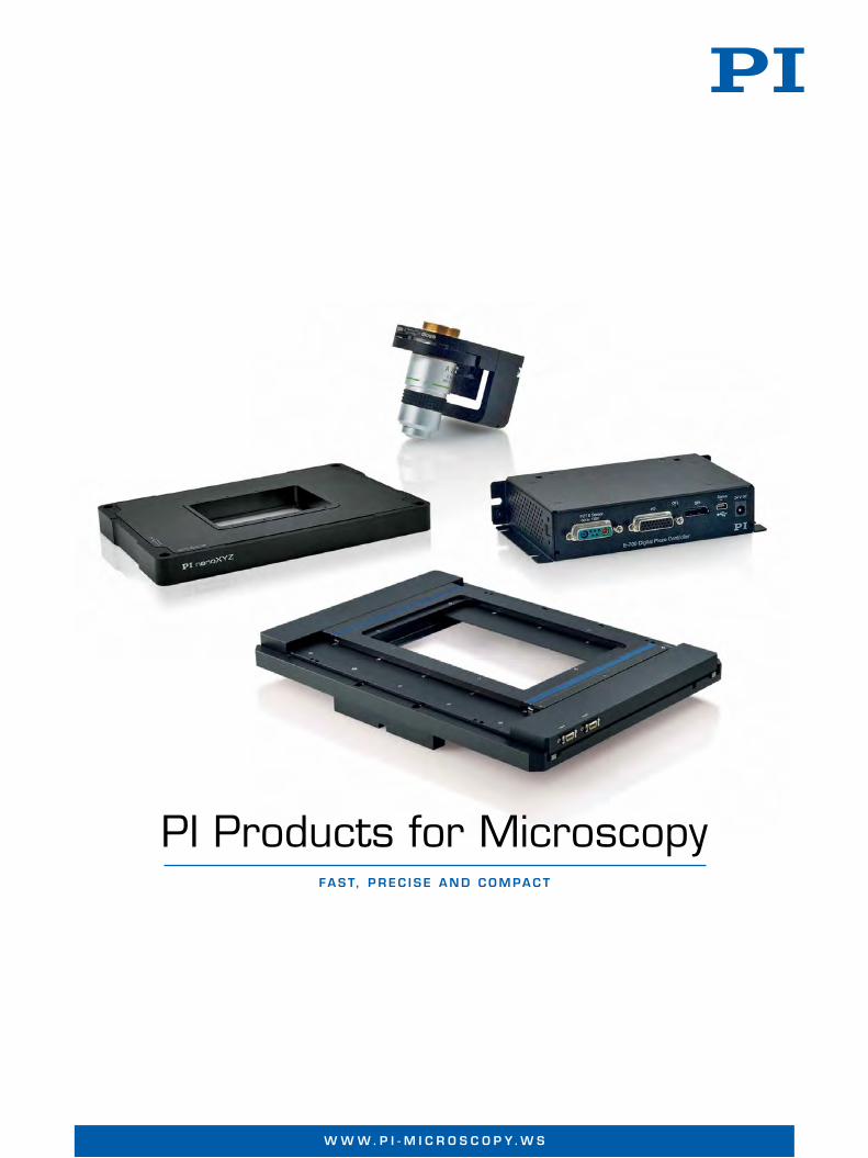
PI Products for MicroscopyFa s t, P r e c i s e a n d c o m Pa c t
W W W . P i - m i c r o s c o P Y . W s

2
W W W . P i - m i c r o s c o P Y . W s
However, if one considers the requirementsof individual applications more closely, it be-comes apparent that the details of the requi-rements are quite different.
Manual XY Motion - Vertical to the OpticalAxis
Manual stages for high-resolution techni-ques are mainly used for the positioning of3x1“ slides or individual Petri dishes. This
Positioning Tasks in Microscopy
Almost all microscopic techniques have similar basic requirements in regard to the positioning elements: compact design andvery high accuracy. Often, many individualimages are to be taken during the examina-tion of a sample in as short a time as possibleor dynamic processes are to be observed –both tasks place great demands on the dynamics of the stage.
2
PI Products for MicroscopyFAST, PREC ISE AND COMPACT
W W W . P I - M I C R O S C O P Y. W S
Contents Products
XY(Z) Piezo System for Super-Resolution Microscopy (P-545.xC) . . . . . . . . . . . . . . . . . . . . 6XY(Z) Piezo System for High-Resolution Microscopy (P-545.xR) . . . . . . . . . . . . . . . . . . . . . . 8 XY(Z) Piezo System for Fast Tracking (P-545.xD) . . . . . . . . . . . . . . . . . . . . . . . . . . . . . . . . . . 9Digital Piezo Controller for Three Channels (E-545) . . . . . . . . . . . . . . . . . . . . . . . . . . . . . . . . 10Manual XY Stage (M-545) . . . . . . . . . . . . . . . . . . . . . . . . . . . . . . . . . . . . . . . . . . . . . . . . . . . . 11Z Microscopy Scanner for Sample Positioning (P-736) . . . . . . . . . . . . . . . . . . . . . . . . . . . . . 12PIFOC® Objective Scanning System 100 µm PD72Z1x with Controller . . . . . . . . . . . . . . . . 14PIFOC® Objective Scanning System up to 400 μm PD72Z2x/4x with Controller . . . . . . . . . 16Compact and Cost-Optimized Digital Piezo Controller (E-709.PR/.SR/.CR) . . . . . . . . . . . . . 18XY Stage System with Piezo Linear Drive, Controller and Joystick (M26821LNJ/OJ) . . . . 20PIFOC® Z Sample Focus Positioner (P-737) . . . . . . . . . . . . . . . . . . . . . . . . . . . . . . . . . . . . . . . 22Miniature Tip/Tilt Mirror (S-334) . . . . . . . . . . . . . . . . . . . . . . . . . . . . . . . . . . . . . . . . . . . . . . . . 22Open-Frame Microscope Stage System (MD5422L) . . . . . . . . . . . . . . . . . . . . . . . . . . . . . . . 22
PI Technology
Digital Motion Controllers . . . . . . . . . . . . . . . . . . . . . . . . . . . . . . . . . . . . . . . . . . . . . . . . . . . . 23Position Sensor Technology: Capacitive Sensors, Strain Sensors, Linear Encoders . . . . . 25PILine® Ultrasonic Piezo Motors . . . . . . . . . . . . . . . . . . . . . . . . . . . . . . . . . . . . . . . . . . . . . . . 26PICMA® Piezo Actuators . . . . . . . . . . . . . . . . . . . . . . . . . . . . . . . . . . . . . . . . . . . . . . . . . . . . . . 28Flexure Guides . . . . . . . . . . . . . . . . . . . . . . . . . . . . . . . . . . . . . . . . . . . . . . . . . . . . . . . . . . . . . . 30
Endothelial cells as seen underthe microscope. Source: LemkeGroup, EMBL Heidelberg
Vorspannseiten_Layout 1 13.04.12 09:42 Seite 2
3
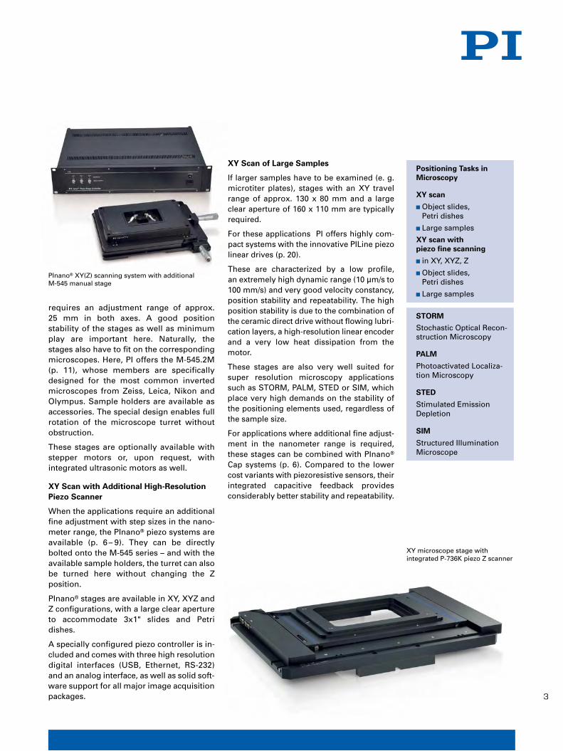
XY Scan of Large Samples
If larger samples have to be examined (e. g.microtiter plates), stages with an XY travelrange of approx. 130 x 80 mm and a largeclear aperture of 160 x 110 mm are typicallyrequired.
For these applications PI offers highly com-pact systems with the innovative PILine piezolinear drives (p. 20).
These are characterized by a low profile, an extremely high dynamic range (10 μm/s to100 mm/s) and very good velocity constancy,position stability and repeatability. The highposition stability is due to the combination ofthe ceramic direct drive without flowing lubri-cation layers, a high-resolution linear encoderand a very low heat dissipation from themotor.
These stages are also very well suited forsuper resolution microscopy applicationssuch as STORM, PALM, STED or SIM, whichplace very high demands on the stability ofthe positioning elements used, regardless ofthe sample size.
For applications where additional fine adjust-ment in the nanometer range is required,these stages can be combined with PInano®
Cap systems (p. 6). Compared to the lowercost variants with piezoresistive sensors, theirintegrated capacitive feedback provides considerably better stability and repeatability.
3
requires an adjustment range of approx.25 mm in both axes. A good position stability of the stages as well as minimumplay are important here. Naturally, the stages also have to fit on the correspondingmicroscopes. Here, PI offers the M-545.2M(p. 11), whose members are specifically designed for the most common inverted microscopes from Zeiss, Leica, Nikon andOlympus. Sample holders are available asaccessories. The special design enables fullrotation of the microscope turret without obstruction.
These stages are optionally available withstepper motors or, upon request, with integrated ultrasonic motors as well.
XY Scan with Additional High-ResolutionPiezo Scanner
When the applications require an additionalfine adjustment with step sizes in the nano-meter range, the PInano® piezo systems areavailable (p. 6 – 9). They can be directly bolted onto the M-545 series – and with theavailable sample holders, the turret can alsobe turned here without changing the Z position.
PInano® stages are available in XY, XYZ andZ configurations, with a large clear apertureto accommodate 3x1" slides and Petri dishes.
A specially configured piezo controller is in-cluded and comes with three high resolutiondigital interfaces (USB, Ethernet, RS-232)and an analog interface, as well as solid soft-ware support for all major image acquisitionpackages.
W W W . P I - M I C R O S C O P Y. W S
Positioning Tasks in Microscopy
XY scan
� Object slides, Petri dishes
� Large samples
XY scan with piezo fine scanning
� in XY, XYZ, Z
� Object slides, Petri dishes
� Large samples
STORM
Stochastic Optical Recon-struction Microscopy
PALM
Photoactivated Localiza-tion Microscopy
STED
Stimulated Emission Depletion
SIM
Structured IlluminationMicroscope
XY microscope stage with integrated P-736K piezo Z scanner
PInano® XY(Z) scanning system with additional M-545 manual stage
Vorspannseiten_Layout 1 13.04.12 09:42 Seite 3

4
W W W . P i - m i c r o s c o P Y . W s
Sample Positioning
For sample positioning, PI offers PInano® Zpiezo stages – either with a 100 or 200 μmstroke (p. 12). The free aperture accommo-dates 3x1'' slides, the profile is very low andthus easy to integrate. As a result of the settling times in the range of a few milli-seconds, Z stacks can be quickly recorded,which considerably reduces the measure-ment times.
For larger samples, either P-737 Z stages formicrotiter plates (p. 22) or PInano® systemswith 160 x 110 mm clear aperture (see figureon p. 13) are suitable.
For XY positioning, there are suitable M-545stages (p. 11) and the M26821LxJ systemsfor larger samples (p. 20).
Objective Positioning
In the case of objective positioning, the application requirements are identical tothose of sample positioning – precision andshort settling time. In addition, however,coupling to the microscope must be possi-ble with different thread types as well as atdifferent angles. This is guaranteed by thePIFOC® systems with their easily exchange-able PI QuickLock thread inserts (p. 14 –17).
Specially in the area of multi-photon microscopy, even greater travel ranges aredesired due to the greater penetration depthof the IR pump light. For this purpose, systems with travel ranges of up to 500 µm(1 mm on request) are available. Even withlarge objectives, short settling times of approx. 10 ms and thus fast Z stack imagesare achieved. For macro objectives with ahigh NA value (numeric aperture), there are
XYZ tracking
Z scan
� Z stack acquisition
� Sample positioning
� Objective positioning
Autofocus
� Drift compensation
XY and XYZ Tracking with High Dynamics
If individual molecules are to be examined, afast positioning system is required that cankeep up with the small but very rapid andstochastically distributed molecule move-ments. In these applications, a small travelrange (approx. 50 μm) is usually sufficientbut in return much higher dynamics are re-quired. The P-545.3D7 PInano® track systemwith its settling time of typically 5 ms (p. 9) iswell suited to this purpose.
Z Motion in the Direction of the OpticalAxis
A coarse adjustment system in the Z direction is already integrated in light mi-croscopes by the manufacturer. In additionto this, there are two different applicationareas for PI products in the area of Z fine adjustment:
� Autofocus or drift compensation
� Fast Z stacks for 3D techniques such asconfocal or multi-photon microscopy
Z Stack Acquisition
In the case of Z stack acquisition, a largenumber of images typically have to be takenwith a step size close to the resolution limitof the microscope. The configuration of themicroscope and the sample to be moved de-termines whether the sample or the microscope objective should be moved. Inthe case of upright microscopes and large orvery sensitive samples, the tendency is toadjust the objective and with inverted microscopes and small samples to adjust thesample.
4
W W W . P I - M I C R O S C O P Y. W S
PIFOC® in an inverted microscope
PInano® piezo tracking stage
Vorspannseiten_Layout 1 13.04.12 09:42 Seite 4

55
PIFOC® objective positioners with a largeclear aperture (up to 29 mm with a M32thread).
The PIFOC® positioners are driven with a digital controller (p. 18), which can be opera-ted via an analog input or digital interfaces(USB, RS-232). The system, consisting of adigital controller and a PIFOC® positionerwith capacitive feedback, is characterized bymaximum flexibility, easy operation and it isalso more favorably priced than previoussystems that use analog electronics (p. 23).
Autofocus or Drift Compensation
Typical autofocus applications arise when expanded samples are to be scanned in the XY direction, e. g. to compensate for a wedgeerror inside a fixed microtitre plate. For thispurpose, PIFOC® positioners (p. 14) and thepiezo Z stages (p. 12 – 17) have enough travelrange and in addition they offer short settlingtimes and high throughput rates.
In the case of long term measurements, the Zdrift of the microscope and the mountingparts that influence the distance between theobjective and the sample is a problem. Theimage either becomes blurred or drifts, i. e.the focus moves to another area of the sam-ple.
W W W . P I - M I C R O S C O P Y. W S
To prevent this, the distance between the objective and the sample must be activelycompensated by an objective or samplestage. If an autofocus signal is already present, PIFOC® systems (p. 14 –17) or piezoZ stages (p. 12) can be used for this purpose.The controller can be switched to autofocusmode, if the autofocus signal is sent to theanalog input of the digital controller. The dis-tance between the sample and objective iskept constant.
With one software command the piezo stagecan be referenced to the internal sensoragain and then used e. g. for Z stack images.
The products listed here are only a small selection of the PI product range. If you cannot find the right solution for your appli-cations – we will be happy to assist you! Youcan find your closest PI office on the back ofthis brochure.
PIFOC® system with QuickLock inserts and E-709 controller
Vorspannseiten_Layout 1 13.04.12 09:42 Seite 5
6
W W W . P i - m i c r o s c o P Y . W s
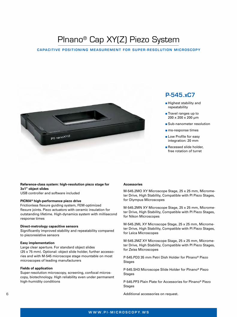
PInano® Cap XY(Z) Piezo SystemCAPAC IT IVE POS IT ION ING MEASUREMENT FOR SUPER -RESOLUT ION MICROSCOPY
Reference-class system: high-resolution piezo stage for3x1" object slidesUSB controller and software included
PICMA® high-performance piezo driveFrictionless flexure guiding system, FEM-optimized flexure joints. Piezo actuators with ceramic insulation for outstanding lifetime. High-dynamics system with millisecondresponse times
Direct-metrology capacitive sensorsSignificantly improved stability and repeatability comparedto piezoresistive sensors
Easy implementationLarge clear aperture. For standard object slides (25 x 75 mm). Optional: object slide holder, further accesso-ries and with M-545 microscope stage mountable on mostmicroscopes of leading manufacturers
Fields of applicationSuper-resolution microscopy, screening, confocal micros-copy, biotechnology. High reliability even under permanenthigh-humidity conditions
P-545.xC7� Highest stability and
repeatability
� Travel ranges up to 200 x 200 x 200 µm
� Sub-nanometer resolution
� ms-response times
� Low Profile for easy integration: 20 mm
� Recessed slide holder, free rotation of turret
© P
hys
ik In
stru
men
te (
PI)
Gm
bH
& C
o. K
G 2
012.
Su
bje
ct t
o c
han
ge
wit
ho
ut
no
tice
. Lat
est
rele
ases
ava
ilab
le a
t w
ww
.pi.w
s. 1
2/03
/26.
0
Accessories
M-545.2MO XY Microscope Stage, 25 x 25 mm, Microme-ter Drive, High Stability, Compatible with PI Piezo Stages, for Olympus Microscopes
M-545.2MN XY Microscope Stage, 25 x 25 mm, Microme-ter Drive, High Stability, Compatible with PI Piezo Stages, for Nikon Microscopes
M-545.2ML XY Microscope Stage, 25 x 25 mm, Microme-ter Drive, High Stability, Compatible with PI Piezo Stages,for Leica Microscopes
M-545.2MZ XY Microscope Stage, 25 x 25 mm, Microme-ter Drive, High Stability, Compatible with PI Piezo Stages,for Zeiss Microscopes
P-545.PD3 35 mm Petri Dish Holder for PInano® Piezo Stages
P-545.SH3 Microscope Slide Holder for PInano® Piezo Stages
P-545.PP3 Plain Plate for Accessories for PInano® PiezoStages
Additional accessories on request.
N A N O P O S I T I O N I N G & P I E Z O E L E C T R I C S | W W W . P I . W S
P545_C7_Datasheet_QX7_Layout 1 16.04.12 10:23 Seite 1

7
Pie
zo S
can
nin
g
Sys
tem
s 2-
an
d 3
-Axi
s
P-545.2C7 P-545.3C7 Units Tolerance
Active axes X, Y X, Y, Z
Motion and positioning
Integrated sensor Capacitive Capacitive
Closed-loop travel 200 x 200 200 x 200 x 200 µm
Closed-loop resolution* < 1 < 1 nm typ.
Mechanical properties
Push / pull force capacity 50 / 30 50 / 30 N max.
Recommended load** 0.5 0.5 kg max.
Drive properties
Piezo ceramics PICMA® P-885 PICMA® P-885
Electrical capacitance 6 (X, Y) 6 (X, Y), 12 (Z) µF ±20%
Miscellaneous
Material Aluminum Aluminum
Mass 1 1.2 kg ±5%
Cable length 1.5 1.5 m ±10 mm
Piezo Controllers E-545 (included in delivery)
Communication interfaces Ethernet (TCP/IP), USB, RS-232
Control input socket BNC
Command set PI General Command Set (GCS)
User software PIMikroMove
Software drivers LabVIEW drivers, shared libraries for Windows and Linux
Supported functionality Wave generator, data recorder, macro programming, auto zero, trigger I/O, MetaMorph, µManager, MATLAB
Operating temperature range 5 to 50°C
Controller dimensions 450 x 88 x 343 + mounting rails
* With flexure guiding system resolution is not limited by friction or stiction. Value given is noise equivalent motion measured with interferometer.** For dynamic operation. Higher dynamics is possible with a reduced load.Ask about custom designs!
Accessories: sample holder, dimensions in mm
P-545, dimensions in mm Accessories: Petri dish holder, dimensions in mm
N A N O P O S I T I O N I N G & P I E Z O E L E C T R I C S | W W W . P I . W S
Lin
ear
Act
uat
ors
&
Mo
tors
Nan
om
etro
log
yH
exap
od
Sys
tem
sM
icro
po
siti
on
ing
Ap
pen
dix
P545_C7_Datasheet_QX7_Layout 1 16.04.12 10:23 Seite 2
8
W W W . P i - m i c r o s c o P Y . W s
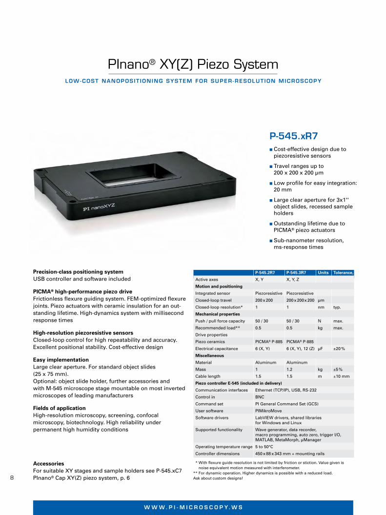
PInano® XY(Z) Piezo SystemLOW-COST NANOPOS IT ION ING SYSTEM FOR SUPER -RESOLUT ION MICROSCOPY
P-545.xR7� Cost-effective design due to
piezoresistive sensors
� Travel ranges up to 200 x 200 x 200 µm
� Low profile for easy integration:20 mm
� Large clear aperture for 3x1'' object slides, recessed sampleholders
� Outstanding lifetime due toPICMA® piezo actuators
� Sub-nanometer resolution, ms-response times
Precision-class positioning systemUSB controller and software included
PICMA® high-performance piezo driveFrictionless flexure guiding system. FEM-optimized flexurejoints. Piezo actuators with ceramic insulation for an out-standing lifetime. High-dynamics system with millisecondresponse times
High-resolution piezoresistive sensorsClosed-loop control for high repeatability and accuracy. Excellent positional stability. Cost-effective design
Easy implementationLarge clear aperture. For standard object slides (25 x 75 mm). Optional: object slide holder, further accessories and with M-545 microscope stage mountable on most inverted microscopes of leading manufacturers
Fields of applicationHigh-resolution microscopy, screening, confocal microscopy, biotechnology. High reliability under permanent high humidity conditions
P-545.2R7 P-545.3R7 Units Tolerance,
Active axes X, Y X, Y, Z
Motion and positioning
Integrated sensor Piezoresistive Piezoresistive
Closed-loop travel 200 x 200 200 x 200x 200 µm
Closed-loop resolution* 1 1 nm typ.
Mechanical properties
Push / pull force capacity 50 / 30 50 / 30 N max.
Recommended load** 0.5 0.5 kg max.
Drive properties
Piezo ceramics PICMA® P-885 PICMA® P-885
Electrical capacitance 6 (X, Y) 6 (X, Y), 12 (Z) µF ±20 %
Miscellaneous
Material Aluminum Aluminum
Mass 1 1.2 kg ±5 %
Cable length 1.5 1.5 m ±10 mm
Piezo controller E-545 (included in delivery)
Communication interfaces Ethernet (TCP/IP), USB, RS-232
Control in BNC
Command set PI General Command Set (GCS)
User software PIMikroMove
Software drivers LabVIEW drivers, shared libraries for Windows and Linux
Supported functionality Wave generator, data recorder, macro programming, auto zero, trigger I/O, MATLAB, MetaMorph, µManager
Operating temperature range 5 to 50°C
Controller dimensions 450 x 88 x 343 mm + mounting rails
AccessoriesFor suitable XY stages and sample holders see P-545.xC7 PInano® Cap XY(Z) piezo system, p. 6
* With flexure guide resolution is not limited by friction or stiction. Value given isnoise equivalent motion measured with interferometer.
** For dynamic operation. Higher dynamics is possible with a reduced load.Ask about custom designs!
W W W . P I - M I C R O S C O P Y. W S
P545_R7_ES_Datasheet_Layout 1 16.04.12 10:27 Seite 1
9
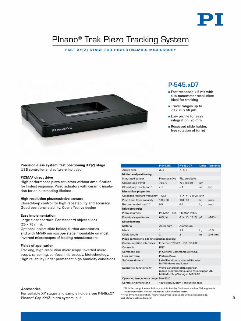
PInano® Trak Piezo Tracking SystemFAST XY (Z ) STAGE FOR H IGH -DYNAMICS MICROSCOPY
P-545.2D7 P-545.3D7 Units Tolerance
Active axes X, Y X, Y, Z
Motion and positioning
Integrated sensor Piezoresistive Piezoresistive
Closed-loop travel 70 x 70 70 x 70 x 50 µm
Closed-loop resolution* < 1 < 1 nm typ.
Mechanical properties
Unloaded resonant frequency 1 (X,Y) 1 (X, Y), 0.8 (Z) kHz
Push / pull force capacity 100 / 30 100 / 30 N max.
Recommended load** 0.5 0.5 kg max.
Drive properties
Piezo ceramics PICMA® P-885 PICMA® P-885
Electrical capacitance 6 (X, Y) 6 (X, Y), 12 (Z) µF ±20 %
Miscellaneous
Material Aluminum Aluminum
Mass 1 1.2 kg ±5 %
Cable length 2 2 m ±10 mm
Piezo controller E-545 (included in delivery)
Communication interfaces Ethernet (TCP/IP), USB, RS-232
Control in BNC
Command set PI General Command Set (GCS)
User software PIMikroMove
Software drivers LabVIEW drivers, shared libraries for Windows and Linux
Supported functionality Wave generator, data recorder, macro programming, auto zero, trigger I/O, MetaMorph, µManager, MATLAB
Operating temperature range 5 to 50°C
Controller dimensions 450 x 88 x 343 mm + mounting rails
AccessoriesFor suitable XY stages and sample holders see P-545.xC7 PInano® Cap XY(Z) piezo system, p. 6
Precision-class system: fast positioning XY(Z) stageUSB controller and software included
PICMA® direct driveHigh-performance piezo actuators without amplification for fastest response. Piezo actuators with ceramic insula-tion for an outstanding lifetime
High-resolution piezoresistive sensorsClosed-loop control for high repeatability and accuracy. Good positional stability. Cost-effective design
Easy implementationLarge clear aperture. For standard object slides (25 x 75 mm). Optional: object slide holder, further accessories and with M-545 microscope stage mountable on most inverted microscopes of leading manufacturers
Fields of applicationTracking, high-resolution microscopy, inverted micro-scopy, screening, confocal microscopy, biotechnology. High reliability under permanent high humidity conditions
P-545.xD7� Fast response < 5 ms with
sub-nanometer resolution:ideal for tracking
� Travel ranges up to 70 x 70 x 50 µm
� Low profile for easy integration: 20 mm
� Recessed slide holder, free rotation of turret
* With flexure guide resolution is not limited by friction or stiction. Value given isnoise equivalent motion measured with interferometer.
** For dynamic operation. Higher dynamics is possible with a reduced load.Ask about custom designs!
W W W . P I - M I C R O S C O P Y. W S
P545_xD7_ES_Datasheet_Layout 1 16.04.12 10:29 Seite 1

10
W W W . P i - m i c r o s c o P Y . W sN A N O P O S I T I O N I N G & P I E Z O E L E C R I C S | W W W . P I . W S
Lin
ear
Act
uat
ors
&M
oto
rsN
ano
po
siti
on
ing
&
Pie
zoel
ectr
ics
Nan
om
etro
log
yH
exap
od
Sys
tem
sM
icro
po
siti
on
ing
Ap
pen
dix
PInano® Piezo ControllerTHREE CHANNELS WITH USB INTERFACE
E-545� Low-noise
24 bit D/A converter
� 25 kHz sampling rate
� Linearization for piezoresistive sensors
� Notch filter for higher bandwidth
� TCP/IP, USB, RS-232 and three analog interfaces
Controller for P-545 PInano® piezo nanopositioner With fast digital and analog interfaces. For piezoresistivestrain sensors (PRS) or capacitive sensors
FunctionsGeneral Command Set (GCS). Software drivers for LabVIEW, shared libraries for Windows and Linux Wave Generator. Data recorder. Macro programming
Supported softwareMetaMorph, µManager, MATLAB
E-545.3RD E-545.3CD
Function Piezo Servo Controller for PInano® positioner
Sensor type Piezoresistive Capacitive
Axes 3 3
Servo characteristics P-I (analog), notch filter P-I (analog), notch filter
Amplifier
Min. output voltage -20 to 120 V -20 to 120 V
Peak output current, < 5 ms 140 mA 140 mA
Average current 60 mA 60 mA
Current limitation Short-circuit-proof Short-circuit-proof
Voltage gain 10 ±0.1 10 ±0.1
Interface and operation
Communication interfaces Ethernet (TCP/IP), USB, RS-232
Piezo system connection Sub-D 25
Analog In 3x BNC
Command set PI General Command Set (GCS)
User software PIMikroMove
Software drivers LabVIEW drivers, shared libraries for Windows and Linux
Supported functionality Wave generator, data recorder, macro programming, auto zero, trigger I/O, MATLAB, MetaMorph, µManager
Miscellaneous
Operating temperature range 5 to 50°C
Dimensions 450 x 88 x 343 mm + mounting rails
Overheat protection Deactivation at 85°C
Operating voltage 90 – 120, 220 – 264 VAC © P
hys
ik In
stru
men
te (
PI)
Gm
bH
& C
o. K
G 2
012.
Su
bje
ct t
o c
han
ge
wit
ho
ut
no
tice
. Lat
est
rele
ases
ava
ilab
le a
t w
ww
.pi.w
s. 1
2/03
/30.
0
Related productsP-545.xR7 PInano® XY(Z) Piezo SystemM-545 Open-Frame Microscope StageE-500 • E-501 Modular Piezo Controller
E545_Datasheet_Layout 1 16.04.12 10:44 Seite 1

11
Open-Frame Microscope StageLOW PROF ILE , LOW DR IFT DES IGN, LONG TRAVEL RANGE
Standard-class, manual XY microscope stageCoarse adjustment for P-545 piezo nanopositioning systems. Stiff design enables optimal scanning and sett-ling behavior
Micrometer screw or optional stepper motor driveThe stage can be supplemented with motorized actuators, controller and joystick (see accessories)
Field of applicationFor inverted microscopes made by Nikon (TI), Zeiss (Axio Observer), Leica (DMI), and Olympus (IX2). Versions for other microscopes are available on request
M-545� Stable platform for P-545
PInano® piezo nanopositio-ning systems
� Low profile for easy integration: 30 mm
� Travel range 25 x 25 mm
� Micrometer screws, motorupgrade available
� For inverted microscopesmade by Nikon, Zeiss, Leica,and Olympus
M-545.2M Units Tolerance
Active axes X, Y
Motion and positioning
Travel range 25 x 25 mm
Min. incremental motion 1 µm typ.
Min. incremental motion with 1 µm typ.M-229 stepper linear actuators
Velocity with M-229 stepper 1.5 mm/s max.linear actuators
Mechanical properties
Max. load 50 N
Preloading 10 N
Miscellaneous
Material Aluminum, stainless steel
Mass 4 kg ±5 %
Compatible nanopositioning stagesP-517 • P-527 Multiaxis Piezo Scanner P-518 • P-528 • P-558 Piezo Tip/Tilt StageP-541.2 • P-542.2 Piezo XY StageP-561 • P-562 • P-563 PIMars Nanopositioning Stage P-545 PInano® Series
Compatible nanopositioning stages (with adapter plate)P-733.2 • P-733.3 XY(Z) Piezo Nanopositioning StageP-736 PInano® Z Microscopy Scanner
Additional accessories and custom designs on request.
AccessoriesM-545.USG M-229 Stepper-Mike Upgrade for M-545 Stages: Includes Stepper-Mikes
M-545.SHP Adapter Plate for Microscope Sample Holder for M-545 XY Microscope Stage
M-545.USC Stepper-Mike Upgrade for M-545 Stages: Includes M-229 Stepper-Mikes, Controller and Joystick(not suitable for M-545.2MZ)
M I C R O P O S I T I O N I N G | W W W . P I . W S
Lin
ear
Act
uat
ors
&
Mo
tors
Nan
op
osi
tio
nin
g &
Pie
zoel
ectr
ics
Nan
om
etro
log
yH
exap
od
Sys
tem
sLi
nea
r S
tag
es
Mu
lti-
Axi
sA
pp
end
ix
© P
hys
ik In
stru
men
te (
PI)
Gm
bH
& C
o. K
G 2
011.
Su
bje
ct t
o c
han
ge
wit
ho
ut
no
tice
. Lat
est
rele
ases
ava
ilab
le a
t w
ww
.pi.w
s. 1
2/03
/23.
0
M545_Datasheet_Layout 1 13.04.12 09:48 Seite 1

12
W W W . P i - m i c r o s c o P Y . W s
PInano® Z Microscopy ScannerLOW-COST, LOW-PROF ILE , WITH D IG ITAL CONTROLLER
P-736� Fastest settling time up to
5 ms
� Low profile for easy integra-tion
� Travel ranges 100 or 200 µm
� Outstanding lifetime due toPICMA® piezo ceramic stacks
� Low-cost due to piezoresis-tive sensors
Precision-class nanopositioning system for high-resolutionmicroscopyOptimized for very fast step-and-settle at target position.Exceptionally low profile of 20 mm for easy integration.With large clear aperture
PICMA® piezo actuator driveCeramic insulation for outstanding life time. Significantly higher humidity resistance. Excellent guidingaccuracy due to FEA-modeled flexure joints
High-resolution piezoresistive sensorsFor stable position control
System with controller and softwareThe compact E-709 piezo controller is included in the delivery. Control is possible via USB, RS-232 and a broadband analog interface. Supports PIMikroMove, PI General Command Set (GCS). Drivers for LabVIEW, shared libraries for Windows and Linux. Compatible with µManager, MetaMorph, MATLAB
Fields of applicationScanning microscopy, 3D imaging, laser technology, interferometry, metrology, biotechnology, micromani-pulation
The PInano® Z stage can be combined with the M-545 XY 25 × 25 mm microscope stage
AccessoriesP-545.PD3 35 mm Petri Dish Holder for PInano®
Piezo Stages
P-545.SH3 Microscope Slide Holder for PInano®
Piezo Stages
P-736.AP1 Adapter Plate P-736 PInano® Z Piezo Slide Scanner to M-545 XY Microscope Stage
N A N O P O S I T I O N I N G & P I E Z O E L E C T R I C S | W W W . P I . W S
© P
hys
ik In
stru
men
te (
PI)
Gm
bH
& C
o. K
G 2
012.
Su
bje
ct t
o c
han
ge
wit
ho
ut
no
tice
. Lat
est
rele
ases
ava
ilab
le a
t w
ww
.pi.w
s. 1
2/03
/22.
0
P736_Datasheet_Layout 1 16.04.12 10:46 Seite 1

13
P-736.ZR1S P-736.ZR2S Units Tolerance
Active axes Z Z
Motion and positioning
Integrated sensor Piezoresistive Piezoresistive
Closed-loop travel 100 200 µm
Open-loop resolution 0.2 0.4 nm typ.
Closed-loop resolution 0.4 0.7 nm typ.
Mechanical properties
Settling time (10 % step width) 5 7 ms
Load capacity 500 500 g max.
Drive properties
Piezo ceramics PICMA® P-885 PICMA® P-885
Miscellaneous
Operating temperature range 15 to 40 15 to 40 °C
Material Aluminum Aluminum
Mass 550 550 g ±5 %
Cable length 1.5 1.5 m 10 mm
Piezo controller E-709 (included in delivery)
Communication interfaces USB, RS-232, SPI
I/O Connector HD-Sub-D 26-pin, 1 analog input 0 to 10 V, 1 sensor monitor 0 to 10 V, 1 digital input (LVTTL, programmable), 1 analog output, 5 digital outputs (LVTTL, 3x predefined, 2x programmable)
Command set PI General Command Set (GCS)
User software PIMikroMove
Software drivers LabVIEW drivers, shared libraries for Windows and Linux
Supported functionality Wave generator, data recorder, auto zero, trigger I/O, MATLAB, MetaMorph, µManager
Controller dimensions 160 x 96 x 33 mm
Custom versions are feasible. The example above shows a P-736version with a particularly large aperture mounted on a motorizedM-687 XY stage
P-736, dimensions in mm
N A N O P O S I T I O N I N G & P I E Z O E L E C T R I C S | W W W . P I . W S
Lin
ear
Act
uat
ors
&
Mo
tors
Pie
zo S
can
nin
g S
yste
ms
Ver
tica
l & T
ip/T
iltN
ano
met
rolo
gy
Hex
apo
d S
yste
mM
icro
po
siti
on
ing
Ap
pen
dix
14
W W W . P i - m i c r o s c o P Y . W s
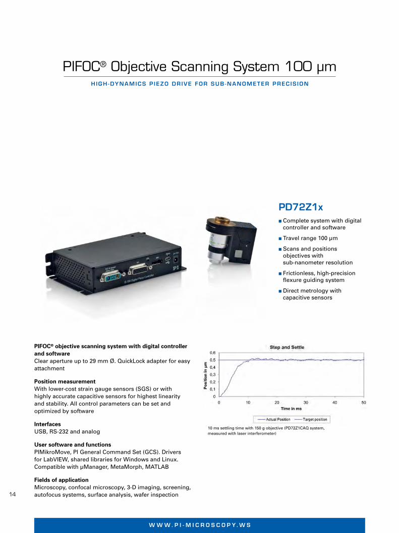
PIFOC® Objective Scanning System 100 µmHIGH -DYNAMICS P IEZO DR IVE FOR SUB -NANOMETER PREC IS ION
PD72Z1x� Complete system with digital
controller and software
� Travel range 100 µm
� Scans and positions objectives with sub-nanometer resolution
� Frictionless, high-precisionflexure guiding system
� Direct metrology with capacitive sensors
PIFOC® objective scanning system with digital controllerand softwareClear aperture up to 29 mm Ø. QuickLock adapter for easyattachment
Position measurementWith lower-cost strain gauge sensors (SGS) or with highly accurate capacitive sensors for highest linearity and stability. All control parameters can be set and optimized by software
InterfacesUSB, RS-232 and analog
User software and functionsPIMikroMove, PI General Command Set (GCS). Drivers for LabVIEW, shared libraries for Windows and Linux. Compatible with µManager, MetaMorph, MATLAB
Fields of applicationMicroscopy, confocal microscopy, 3-D imaging, screening,autofocus systems, surface analysis, wafer inspection
10 ms settling time with 150 g objective (PD72Z1CAQ system, measured with laser interferometer)
N A N O P O S I T I O N I N G & P I E Z O E L E C T R I C S | W W W . P I . W S
© P
hys
ik In
stru
men
te (
PI)
Gm
bH
& C
o. K
G 2
012.
Su
bje
ct t
o c
han
ge
wit
ho
ut
no
tice
. Lat
est
rele
ases
ava
ilab
le a
t w
ww
.pi.w
s. 1
2/03
/30.
0
PD72Z1_Datasheet_Layout 1 30.03.12 13:21 Seite 1
15
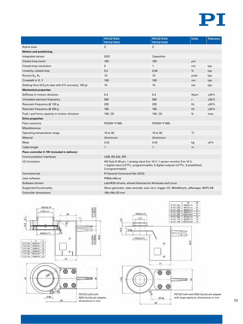
PD72Z1SAA PD72Z1CAA Units Tolerance PD72Z1SAQ PD72Z1CAQ
Active axes Z Z
Motion and positioning
Integrated sensor SGS Capacitive
Closed-loop travel 100 100 µm
Closed-loop resolution 5 1 nm typ.
Linearity, closed-loop 0.2 0.06 % typ.
Runout θX, θY 13 13 µrad typ.
Crosstalk in X, Y 100 100 nm typ.
Settling time (0.5 µm step with 5 % accuracy, 150 g) 10 10 ms typ.
Mechanical properties
Stiffness in motion direction 0.3 0.3 N/µm ±20 %
Unloaded resonant frequency 580 580 z ±20 %
Resonant frequency @ 120 g 235 235 Hz ±20 %
Resonant frequency @ 200 g 180 180 Hz ±20 %
Push / pull force capacity in motion direction 100 / 20 100 / 20 N max.
Drive properties
Piezo ceramics PICMA® P-885 PICMA® P-885
Miscellaneous
Operating temperature range 10 to 50 10 to 50 °C
Material Aluminum Aluminum
Mass 0.22 0.24 kg ±5 %
Cable length 1 1 m
Piezo controller E-709 (included in delivery)
Communication interfaces USB, RS-232, SPI
I/O Connector HD-Sub-D 26-pin, 1 analog input 0 to 10 V, 1 sensor monitor 0 to 10 V, 1 digital input (LVTTL, programmable), 5 digital outputs (LVTTL, 3 predefined, 2 programmable)
Command set PI General Command Set (GCS)
User software PIMikroMove
Software drivers LabVIEW drivers, shared libraries for Windows and Linux
Supported functionality Wave generator, data recorder, auto zero, trigger I/O, MetaMorph, µManager, MATLAB
Controller dimensions 160 x 96 x 33 mm
PD72Z1xAQ with M25-QuickLock adapter, dimensions in mm
PD72Z1xAA with M32-QuickLock adapterwith large aperture, dimensions in mm
N A N O P O S I T I O N I N G & P I E Z O E L E C T R I C S | W W W . P I . W S
Lin
ear
Act
uat
ors
&
Mo
tors
Pie
zo S
can
nin
g
Sys
tem
s Li
nea
rN
ano
met
rolo
gy
Hex
apo
d S
yste
mM
icro
po
siti
on
ing
Ap
pen
dix
PD72Z1_Datasheet_Layout 1 30.03.12 13:21 Seite 2
16
W W W . P i - m i c r o s c o P Y . W s
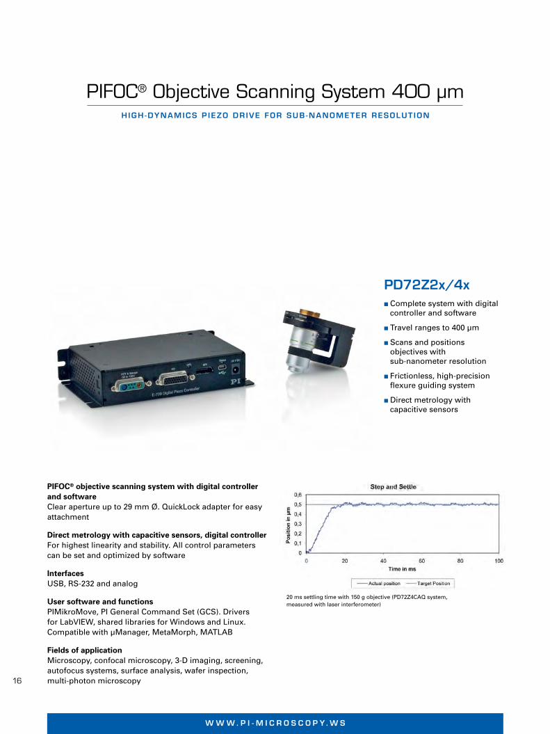
PD72Z2x/4x� Complete system with digital
controller and software
� Travel ranges to 400 µm
� Scans and positions objectives with sub-nanometer resolution
� Frictionless, high-precisionflexure guiding system
� Direct metrology with capacitive sensors
PIFOC® objective scanning system with digital controller and softwareClear aperture up to 29 mm Ø. QuickLock adapter for easyattachment
Direct metrology with capacitive sensors, digital controllerFor highest linearity and stability. All control parameterscan be set and optimized by software
InterfacesUSB, RS-232 and analog
User software and functionsPIMikroMove, PI General Command Set (GCS). Drivers for LabVIEW, shared libraries for Windows and Linux. Compatible with µManager, MetaMorph, MATLAB
Fields of applicationMicroscopy, confocal microscopy, 3-D imaging, screening,autofocus systems, surface analysis, wafer inspection,multi-photon microscopy
PIFOC® Objective Scanning System 400 µmHIGH -DYNAMICS P IEZO DR IVE FOR SUB -NANOMETER RESOLUT ION
20 ms settling time with 150 g objective (PD72Z4CAQ system, measured with laser interferometer)
N A N O P O S I T I O N I N G & P I E Z O E L E C T R I C S | W W W . P I . W S
© P
hys
ik In
stru
men
te (
PI)
Gm
bH
& C
o. K
G 2
012.
Su
bje
ct t
o c
han
ge
wit
ho
ut
no
tice
. Lat
est
rele
ases
ava
ilab
le a
t w
ww
.pi.w
s. 1
2/03
/23.
0
PD72Z2x_Datasheet_Layout 1 30.03.12 13:28 Seite 1

17
PD72Z2CAA/PD72Z2CAQ PD72Z4CAA/PD72Z4CAQ Units Tolerance
Active axes Z Z
Motion and positioning
Integrated sensor Capacitive Capacitive
Closed-loop travel 250 400 µm
Closed-loop resolution 1.5 2.5 nm typ.
Linearity, closed-loop 0.06 0.06 % typ.
Runout θX 6 10 µrad typ.
Runout θY 45 45 µrad typ.
Crosstalk in X 20 60 nm typ.
Crosstalk in Y 40 60 nm typ.
Settling time (0.5 µm step with 5 % accuracy, 150 g) 15 20 ms typ.
Mechanical properties
Stiffness in motion direction 0.17 0.12 N/µm ±20 %
Unloaded resonant frequency 330 230 Hz ±20 %
Resonant frequency @ 150 g 140 120 Hz ±20 %
Push / pull force capacity in motion direction 100 / 20 100 / 20 N max.
Drive properties
Piezo ceramics PICMA® P-885 PICMA® P-885
Miscellaneous
Operating temperature range 10 to 50 10 to 50 °C
Material Aluminum Aluminum
Mass 0.23 0.23 kg ±5 %
Cable length 1.5 1.5 m
Piezo controller E-709 (included in delivery)
Communication interfaces USB, RS-232
I/O Connector HD-Sub-D 26-pin, 1 analog input 0 to 10 V, 1 sensor monitor 0 to 10 V, 1 digital input (LVTTL, programmable), 5 digital outputs (LVTTL, 3 predefined, 2 programmable)
Command set PI General Command Set (GCS)
User software PIMikroMove
Software drivers LabVIEW drivers, shared libraries for Windows and Linux
Supported functionality Wave generator, data recorder, auto zero, trigger I/O, MATLAB, MetaMorph, µManager
Controller dimensions 160 x 96 x 33 mm
PD72ZxCAQ with M25-QuickLock adapter, dimensions in mm
PD72ZxCAA with M32-QuickLock thread adapter with large aperture,dimensions in mm
N A N O P O S I T I O N I N G & P I E Z O E L E C T R I C S | W W W . P I . W S
Lin
ear
Act
uat
ors
&
Mo
tors
Pie
zo S
can
nin
g S
yste
ms
Ver
tica
l & T
ip/T
iltN
ano
met
rolo
gy
Hex
apo
d S
yste
mM
icro
po
siti
on
ing
Ap
pen
dix
PD72Z2x_Datasheet_Layout 1 30.03.12 13:28 Seite 2

18
W W W . P i - m i c r o s c o P Y . W s
E-709� Linearity to 0.02 %
� Fast 25 Mbit/s serial interface
� Comprehensive I/O functions
� Low-cost OEM versions available
� Extensive software support
Fast digital controllerAs bench-top (.xRG) or as OEM board (.xR). Voltage range -30 to 130 V
InterfacesUSB, digital RS-232, fast serial interface with up to 25MBit/s. Additional high-bandwidth analog controlinput/sensor input. Analog output, e.g. for external amplifiers
Comparison of the linearity of a strain gauge sensor with analog controller (top) and the E-709 digital controller (bottom), which improves the linearity by up to one order ofmagnitude
Compact and Cost-Optimized Digital Piezo Controller
FOR SGS, P IEZORES IST IVE AND CAPAC IT IVE SENSORS
User software and functionsPIMikroMove, PI General Command Set (GCS). Drivers for LabVIEW, shared libraries for Windows and Linux.Compatible with µManager, MetaMorph, MATLAB. WaveGenerator. Linearization. Data recorder. Auto zero. TriggerI/O. Software configurable servo parameters
© P
hys
ik In
stru
men
te (
PI)
Gm
bH
& C
o. K
G 2
011.
Su
bje
ct t
o c
han
ge
wit
ho
ut
no
tice
. Lat
est
rele
ases
ava
ilab
le a
t w
ww
.pi.w
s. 1
2/03
/26.
0
N A N O P O S I T I O N I N G & P I E Z O E L E C R I C S | W W W . P I . W S
E709_Datasheet_Layout 1 30.03.12 13:31 Seite 1
19
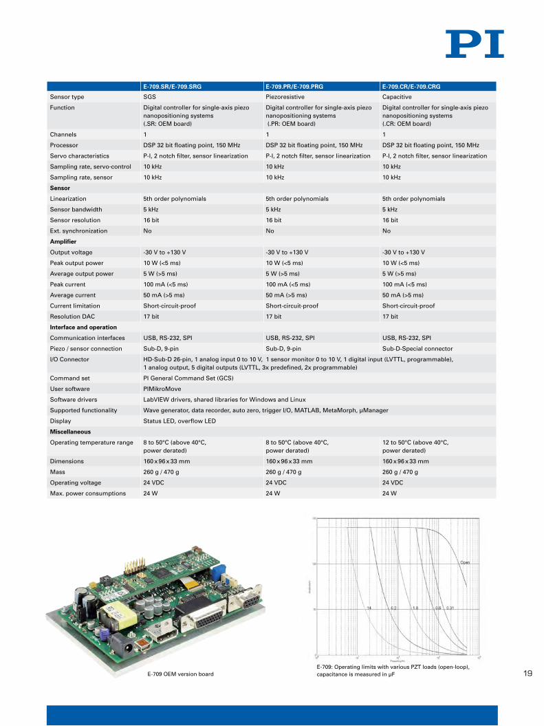
E-709.SR/E-709.SRG E-709.PR/E-709.PRG E-709.CR/E-709.CRG
Sensor type SGS Piezoresistive Capacitive
Function Digital controller for single-axis piezo Digital controller for single-axis piezo Digital controller for single-axis piezo nanopositioning systems nanopositioning systems nanopositioning systems (.SR: OEM board) (.PR: OEM board) (.CR: OEM board)
Channels 1 1 1
Processor DSP 32 bit floating point, 150 MHz DSP 32 bit floating point, 150 MHz DSP 32 bit floating point, 150 MHz
Servo characteristics P-I, 2 notch filter, sensor linearization P-I, 2 notch filter, sensor linearization P-I, 2 notch filter, sensor linearization
Sampling rate, servo-control 10 kHz 10 kHz 10 kHz
Sampling rate, sensor 10 kHz 10 kHz 10 kHz
Sensor
Linearization 5th order polynomials 5th order polynomials 5th order polynomials
Sensor bandwidth 5 kHz 5 kHz 5 kHz
Sensor resolution 16 bit 16 bit 16 bit
Ext. synchronization No No No
Amplifier
Output voltage -30 V to +130 V -30 V to +130 V -30 V to +130 V
Peak output power 10 W (<5 ms) 10 W (<5 ms) 10 W (<5 ms)
Average output power 5 W (>5 ms) 5 W (>5 ms) 5 W (>5 ms)
Peak current 100 mA (<5 ms) 100 mA (<5 ms) 100 mA (<5 ms)
Average current 50 mA (>5 ms) 50 mA (>5 ms) 50 mA (>5 ms)
Current limitation Short-circuit-proof Short-circuit-proof Short-circuit-proof
Resolution DAC 17 bit 17 bit 17 bit
Interface and operation
Communication interfaces USB, RS-232, SPI USB, RS-232, SPI USB, RS-232, SPI
Piezo / sensor connection Sub-D, 9-pin Sub-D, 9-pin Sub-D-Special connector
I/O Connector HD-Sub-D 26-pin, 1 analog input 0 to 10 V, 1 sensor monitor 0 to 10 V, 1 digital input (LVTTL, programmable), 1 analog output, 5 digital outputs (LVTTL, 3x predefined, 2x programmable)
Command set PI General Command Set (GCS)
User software PIMikroMove
Software drivers LabVIEW drivers, shared libraries for Windows and Linux
Supported functionality Wave generator, data recorder, auto zero, trigger I/O, MATLAB, MetaMorph, µManager
Display Status LED, overflow LED
Miscellaneous
Operating temperature range 8 to 50°C (above 40°C, 8 to 50°C (above 40°C, 12 to 50°C (above 40°C, power derated) power derated) power derated)
Dimensions 160 x 96 x 33 mm 160 x 96 x 33 mm 160 x 96 x 33 mm
Mass 260 g / 470 g 260 g / 470 g 260 g / 470 g
Operating voltage 24 VDC 24 VDC 24 VDC
Max. power consumptions 24 W 24 W 24 W
E-709 OEM version boardE-709: Operating limits with various PZT loads (open-loop), capacitance is measured in µF
Lin
ear
Act
uat
ors
&M
oto
rsP
iezo
Dri
vers
S
ing
le-C
han
nel
Nan
om
etro
log
yH
exap
od
Sys
tem
sM
icro
po
siti
on
ing
Ap
pen
dix
N A N O P O S I T I O N I N G & P I E Z O E L E C R I C S | W W W . P I . W S
E709_Datasheet_Layout 1 30.03.12 13:31 Seite 2
20
W W W . P i - m i c r o s c o P Y . W s
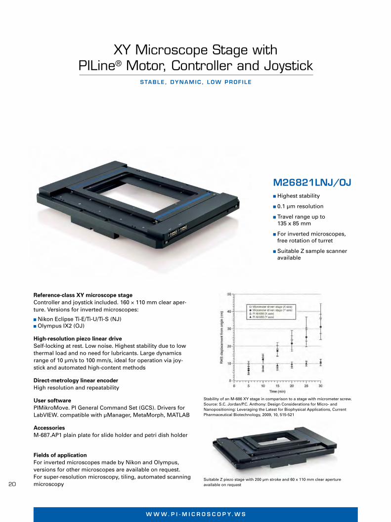
Reference-class XY microscope stageController and joystick included. 160 × 110 mm clear aper-ture. Versions for inverted microscopes:
� Nikon Eclipse Ti-E/Ti-U/Ti-S (NJ) � Olympus IX2 (OJ)
High-resolution piezo linear driveSelf-locking at rest. Low noise. Highest stability due to lowthermal load and no need for lubricants. Large dynamicsrange of 10 µm/s to 100 mm/s, ideal for operation via joy-stick and automated high-content methods
Direct-metrology linear encoderHigh resolution and repeatability
User softwarePIMikroMove. PI General Command Set (GCS). Drivers forLabVIEW. compatible with µManager, MetaMorph, MATLAB
AccessoriesM-687.AP1 plain plate for slide holder and petri dish holder
Fields of applicationFor inverted microscopes made by Nikon and Olympus, versions for other microscopes are available on request. For super-resolution microscopy, tiling, automated scanningmicroscopy
XY Microscope Stage with PILine® Motor, Controller and Joystick
STABLE , DYNAMIC , LOW PROF ILE
Stability of an M-686 XY stage in comparison to a stage with micrometer screw.Source: S.C. Jordan/P.C. Anthony: Design Considerations for Micro- and Nanopositioning: Leveraging the Latest for Biophysical Applications, CurrentPharmaceutical Biotechnology, 2009, 10, 515-521
M26821LNJ/OJ� Highest stability
� 0.1 µm resolution
� Travel range up to 135 x 85 mm
� For inverted microscopes, free rotation of turret
� Suitable Z sample scanneravailable
M I C R O P O S I T I O N I N G | W W W . P I . W S
© P
hys
ik In
stru
men
te (
PI)
Gm
bH
& C
o. K
G 2
012
. Su
bje
ct t
o c
han
ge
wit
ho
ut
no
tice
. Lat
est
rele
ases
ava
ilab
le a
t w
ww
.pi.w
s. 1
2/04
/02.
0
Suitable Z piezo stage with 200 µm stroke and 60 x 110 mm clear aperture available on request
M268x_Datasheet_Layout 1 03.04.12 10:52 Seite 1
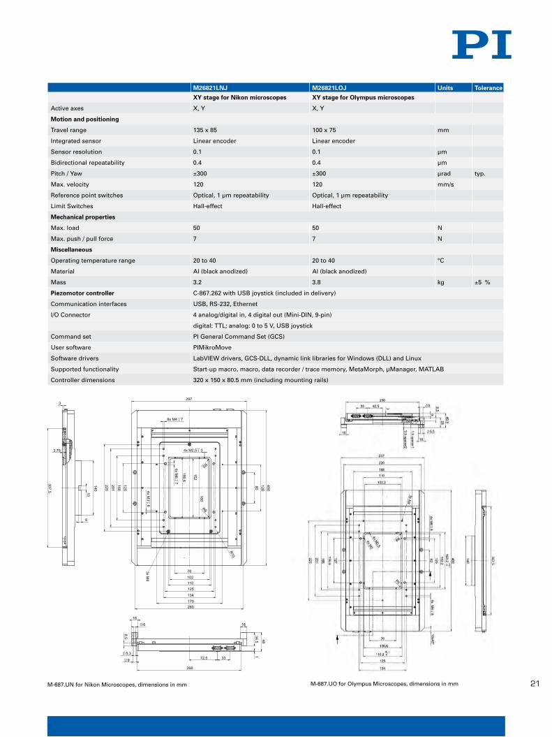
21M-687.UO for Olympus Microscopes, dimensions in mmM-687.UN for Nikon Microscopes, dimensions in mm
M26821LNJ M26821LOJ Units Tolerance
XY stage for Nikon microscopes XY stage for Olympus microscopes
Active axes X, Y X, Y
Motion and positioning
Travel range 135 x 85 100 x 75 mm
Integrated sensor Linear encoder Linear encoder
Sensor resolution 0.1 0.1 µm
Bidirectional repeatability 0.4 0.4 µm
Pitch / Yaw ±300 ±300 µrad typ.
Max. velocity 120 120 mm/s
Reference point switches Optical, 1 µm repeatability Optical, 1 µm repeatability
Limit Switches Hall-effect Hall-effect
Mechanical properties
Max. load 50 50 N
Max. push / pull force 7 7 N
Miscellaneous
Operating temperature range 20 to 40 20 to 40 °C
Material Al (black anodized) Al (black anodized)
Mass 3.2 3.8 kg ±5 %
Piezomotor controller C-867.262 with USB joystick (included in delivery)
Communication interfaces USB, RS-232, Ethernet
I/O Connector 4 analog/digital in, 4 digital out (Mini-DIN, 9-pin)
digital: TTL; analog: 0 to 5 V, USB joystick
Command set PI General Command Set (GCS)
User software PIMikroMove
Software drivers LabVIEW drivers, GCS-DLL, dynamic link libraries for Windows (DLL) and Linux
Supported functionality Start-up macro, macro, data recorder / trace memory, MetaMorph, µManager, MATLAB
Controller dimensions 320 x 150 x 80.5 mm (including mounting rails)
M I C R O P O S I T I O N I N G | W W W . P I . W S
Lin
ear
Act
uat
ors
&
Mo
tors
Nan
op
osi
tio
nin
g &
Pie
zoel
ectr
ics
Nan
om
etro
log
yH
exap
od
Sys
tem
sLi
nea
r S
tag
es
Mu
lti-
Axi
sA
pp
end
ix
M268x_Datasheet_Layout 1 03.04.12 10:52 Seite 2
22
W W W . P i - m i c r o s c o P Y . W s
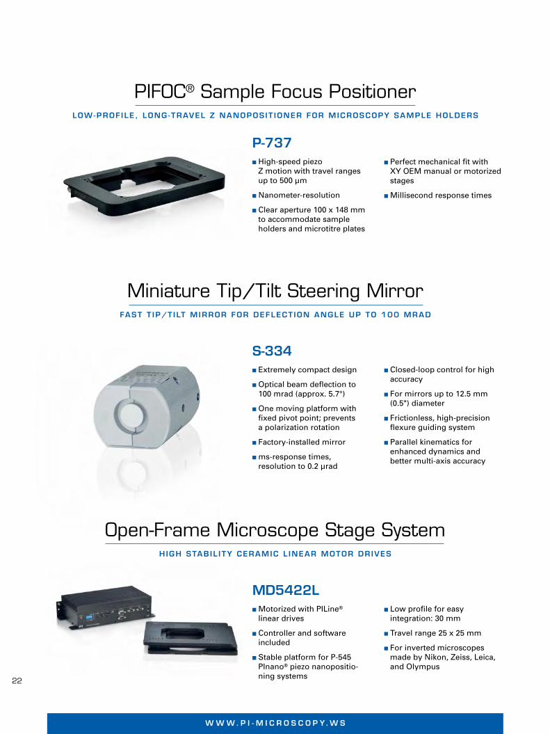
� Perfect mechanical fit withXY OEM manual or motorizedstages
� Millisecond response times
PIFOC® Sample Focus PositionerLOW-PROF ILE , LONG -TRAVEL Z NANOPOS IT IONER FOR MICROSCOPY SAMPLE HOLDERS
Miniature Tip/Tilt Steering MirrorFAST T IP/T ILT MIRROR FOR DEFLECT ION ANGLE UP TO 100 MRAD
Open-Frame Microscope Stage SystemHIGH STAB IL I TY CERAMIC L INEAR MOTOR DR IVES
P-737� High-speed piezo
Z motion with travel rangesup to 500 µm
� Nanometer-resolution
� Clear aperture 100 x 148 mmto accommodate sample holders and microtitre plates
� Closed-loop control for high accuracy
� For mirrors up to 12.5 mm(0.5") diameter
� Frictionless, high-precisionflexure guiding system
� Parallel kinematics for enhanced dynamics and better multi-axis accuracy
S-334� Extremely compact design
� Optical beam deflection to100 mrad (approx. 5.7°)
� One moving platform withfixed pivot point; prevents a polarization rotation
� Factory-installed mirror
� ms-response times, resolution to 0.2 µrad
� Low profile for easy integration: 30 mm
� Travel range 25 x 25 mm
� For inverted microscopesmade by Nikon, Zeiss, Leica,and Olympus
MD5422L� Motorized with PILine®
linear drives
� Controller and software included
� Stable platform for P-545 PInano® piezo nanopositio-ning systems
W W W . P I - M I C R O S C O P Y. W S
P737_S334_MD5422L_Datasheet_Layout 1 16.04.12 10:08 Seite 1

23
Digital Motion ControllersIMPROVED PERFORMANCE THROUGH D IG ITAL PROCESSES
Fast data processing
The incoming pack of data has to be quicklyprocessed in order match classic analog controllers in terms of "real time". For thispurpose, fast processors are required. Depending on the task of the controller, PI uses state-of-the-art signal processors(DSP's), field-programmable gate arrays(FPGA's) or powerful PC solutions. A controlcycle is thereby processed in 0.02 milli-seconds, for example – this corresponds toa servo rate of 50 kHz. Updated sensor dataand control signals also have to be providedcorrespondingly.
Digital data processing forimproving
� of the linearity
� of the path accuracy du-ring the motion (dyna-mic linearity)
� of the control algorithms
Simplified operation
� Access to all parameters
� Recording of the systembehavior
� Access to all functions
� ID chip, reading out ofindividual system data
Additional functions
� Data recorder
� Programmable functiongenerators
� Macro programming andstorage
� Coordinate transforma-tion with parallel kine-matics
� Autofocus algorithms
State-of-the-art interfaces
� USB, TCP/IP, PIO
� Serial real-time interfaces
Digital technology opens up possibilities forimproving performance in control enginee-ring which do not exist with conventionalanalog technology.
A significant advantage of digital controllersfrom PI is that all motion parameters can beoptimized and modified by the user.
This serves to increase the precision and dynamic characteristics as well as the easeof use.
Suitable signal conversion
The most important prerequisite here is thatthe conversion of analog input signals suchas sensor or piezo voltages to digital datatakes place fast and with a high resolution.Information that is lost during conversion remains lost for further processing.
The same holds true for the generation of ananalog signal for controlling the piezo drives.
For this reason, PI employs the lowest noiseand highest stability precision A/D and D/Aconverters available on the market providingup to 24 bit resolution. As a result, analogsignal amplitudes are resolved in over 1 million data points.
Parallel-kinematics 6-axis positioning system with digitalmulti-axis controller ©
Ph
ysik
Inst
rum
ente
(P
I) G
mb
H &
Co
. KG
201
2. S
ub
ject
to
ch
ang
e w
ith
ou
t n
oti
ce. L
ates
t re
leas
es a
vaila
ble
at
ww
w.p
i.ws.
12/
03/2
6.0
W W W . P I . W S
TEC06_Datasheet_Layout 1 13.04.12 09:52 Seite 1

24
W W W . P i - m i c r o s c o P Y . W s
Software for easy operation
The digitization of all process steps meansthe process parameters can be easily acces-sed using software. In addition, PI softwareoffers diagnostic tools and assistance withthe adjustment of settings, such as the graphic display of step responses for the optimization of parameter settings.
Mechanical stiffness, precisely engineered guiding systems, the resolution and band-width of the sensor and the noise level of thevoltage source remain important pre-requisites for high-precision and dynamicpositioning and scanning.
With increasing requirements, however, theoptimization of the performance of a posi-tioning system is increasingly determinedby the controller.
Semi-automated configuration
The adjustment to the system to be operatedtakes place in a few steps through a mainlyautomated configuration dialog. Predefinedparameter sets for each PI stage allow for afast and simple installation. The graphic
Fast and simple system analysis with the PIMikroMove software. This tool is included in delivery
With the single channel E-709 controller, PI introducesthe advantages of digital controllers even for low-cost, single-axis system such as the PIFOC® objectivestage.
display of the actual motion, such as step &settle (captured in the controller's trace memory) facilitates the optimal adaptationof the positioning system to the customer'sapplication. All PI systems can be operatedby the same user interface.
Dynamic control such as velocity, accelera-tion or PID parameters can be changed directly. Since nearly all PI controllers have a trace memory, which is supported by thePIMikroMove user software included in thedelivery, the host PC transforms itself withjust a few clicks into a virtual oscilloscopewith which the settings can be optimizedspecifically for the customer application.
Third-party poftware package
Drivers for PI positioning systems are integrated in popular third party imageacquisition packages such as MetaMorph,μManager, MATLAB or ScanImage, savingthe user valuable time during system setupand programming.
W W W . P I . W S
TEC06_Datasheet_Layout 1 13.04.12 09:52 Seite 2
25
NANOMETER -PREC IS ION MEASUREMENT TECHNOLOGY
Positioning systems that need to provide ac-curacies in the range of a few nanometersand below require a position measurementtechnique that can also detect motion in thisrange. The most important specifications forselecting a suitable method are linearity, resolution (sensitivity), stability, bandwidthand last but not least cost. Another impor-tant factor is the ability to detect the motionof the moving platform. The contact with the movable parts also affects the measuringresult.
PI nanopositioners use three different typesof sensors, capacitive, strain gauges and linear encoders.
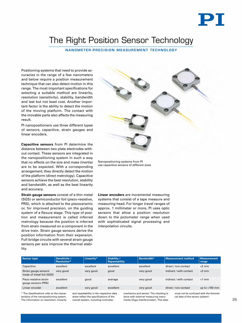
Capacitive sensors from PI determine thedistance between two plate electrodes with -out contact. These sensors are integrated inthe nanopositioning system in such a waythat no effects on the size and mass (inertia)are to be expected. With a corresponding arrangement, they directly detect the motionof the platform (direct metrology). Capacitivesensors achieve the best resolution, stabilityand bandwidth, as well as the best linearityand accuracy.
Strain gauge sensors consist of a thin metal(SGS) or semiconductor foil (piezo-resistive,PRS), which is attached to the piezoceramicor, for improved precision, on the guidingsystem of a flexure stage. This type of posi-tion and measurement is called inferred metrology because the position is inferredfrom strain measured on a component in thedrive train. Strain gauge sensors derive theposition information from their expansion.Full-bridge circuits with several strain gaugesensors per axis improve the thermal stabi-lity.
Linear encoders are incremental measuringsystems that consist of a tape measure andmeasuring head. For longer travel ranges ofapprox. 1 millimeter or more, PI uses opticsensors that allow a position resolutiondown to the pictometer range when usedwith sophisticated signal processing and interpolation circuits.
The Right Position Sensor Technology
Nanopositioning systems from PI use capacitive sensors of different sizes
Sensor type Sensitivity / Linearity* Stability / Bandwidth* Measurement method Measurement Resolution* Repeatability range
Capacitive excellent excellent excellent excellent direct / non-contact <2 mm
Strain gauge sensors very good very good good very good indirect / with contact <2 mmmade of metal foil (SGS)
Piezo-resistive strain excellent good average very good indirect / with contact <1 mmgauge sensors (PRS)
Linear encoder excellent very good excellent very good direct / non-contact up to >100 mm
W W W . P I . W S
* The classifications refer to the charac-teristics of the nanopositioning system.The information on resolution, linearity
and repeatability in the respective datasheet reflect the specifications of theoverall system, including controller,
mechanics and sensor. The checking isdone with external measuring instru-ments (Zygo interferometer). This data
must not be confused with the theoreti-cal data of the sensor system!
© P
hys
ik In
stru
men
te (
PI)
Gm
bH
& C
o. K
G 2
011.
Su
bje
ct t
o c
han
ge
wit
ho
ut
no
tice
. Lat
est
rele
ases
ava
ilab
le a
t w
ww
.pi.w
s. 1
1/10
/25.
0
TEC05_Datasheet_Layout 6 26.03.12 12:07 Seite 1

26
W W W . P i - m i c r o s c o P Y . W s
� Integration levels fromeconomical OEM motorsto multi-axis positioningsystems
� Excellent dynamic pro-perties, fast step & settle
� Basically unlimited travelranges
� Easy mechanicalintegration
� Self-locking at rest
� Holding force up to 15 N
� Velocity up to 500 mm/s
� Resolution to 0.05 µm(50 nm)
Direct-driven PILine® linear motors
These linear drives dispense with the mecha-nical complexity of classical rotary motor/gear/leadscrew combinations. These compo-nents can be very susceptible to wear, espe-cially in miniaturized systems.
The simplicity of the ultrasonic linear motorpromotes its precision, reliability and cost ef-ficiency. An integral part of the ultrasonicpiezomotor is a piezo ceramic that is preloa-ded against a moving runner with a coupling
PILine® Ultrasonic PiezomotorsCOMPACT DR IVES , FAST AND SELF - LOCK ING
W W W . P I . W S
Motor-leadscrew combinations (above) transform the rotational motion of the motorinto linear motion. Due to play in the mechanical components responsiveness is limited.Linear motors such as PILine® generate linear motion directly and provide much fasterresponse and better stability
element. The piezo element is electrically ex-cited to produce high-frequency oscillationsthat cause the runner to move.
Piezomotors are self-locking
The preload of the piezoceramic actuatoragainst the runner ensures that the drive self-locks at rest and when powered down. As aresult, it does not consume any power, itdoes not heat up and keeps the position sta-ble mechanically. Applications with a shortduty cycle, that are battery-operated or heat-sensitive benefit from these characteristics.
Lifetime and reliability
The motion of the piezoceramic actuator isbased on crystalline effects and is not subjectto any wear. The coupling to the runner, onthe other hand, is subject to friction effects.Depending on the operating mode, runningdistances over 2000 km or a MTBF of20000 hours are achieved.
Dynamics in use
The stiff design, direct coupling and fast re-sponse of the piezo ceramics to electric in-puts allows for very fast start / stop behaviorand velocities to hundreds of mm/sec.
Patented technology
The products described in this document arein part protected by the following patents:
US Pat. No. 6,765,335B2
European Patent No. 1267425B1 ©P
hys
ikIn
stru
men
te(P
I)G
mb
H&
Co
.KG
2012
.Su
bje
ctto
chan
ge
wit
ho
ut
no
tice
.Lat
est
rele
ases
avai
lab
leat
ww
w.p
i.ws.
12/0
3/14
.0
TEC01_Datasheet_QX7.qxd:Layout 1 14.03.2012 13:03 Uhr Seite 1
27
Piezomotors for all applications –e. g. in vacuum environments and strongmagnetic fields
Piezomotors from PI are intrinsically vacuum-compatible and suitable for operation instrong magnetic fields. Special versions areoffered for this purpose. Nanometer resolu-tion or forces up to several 100 N can beachieved with PiezoWalk® linear motors.
W W W . P I . W S
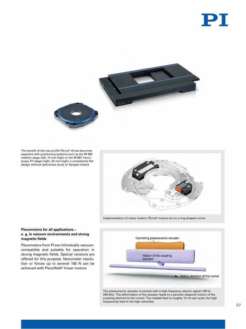
The benefit of the low profile PILine® drives becomesapparent with positioning systems such as the M-660rotation stage (left, 14 mm high) or the M-687 micro-scopy XY stage (right, 25 mm high): a consistently flatdesign without lead screw ducts or flanged motors
Implementation of rotary motion: PILine® motors act on a ring-shaped runner
The piezoceramic actuator is excited with a high frequency electric signal (100 to200 kHz). The deformation of the actuator leads to a periodic diagonal motion of thecoupling element to the runner. The created feed is roughly 10 nm per cycle; the highfrequencies lead to the high velocities
TEC01_Datasheet_QX7.qxd:Layout 1 14.03.2012 13:03 Uhr Seite 2

28
W W W . P i - m i c r o s c o P Y . W s
© P
hys
ik In
stru
men
te (
PI)
Gm
bH
& C
o. K
G 2
011.
Su
bje
ct t
o c
han
ge
wit
ho
ut
no
tice
. Lat
est
rele
ases
ava
ilab
le a
t w
ww
.pi.w
s. 1
1/10
/26.
0
� Sub-nanometer resolution
� High reliability and superior lifetime throughfully ceramic insulation
� Low operating voltage< 150 V
� High dynamics: responsetimes in the range of afew microseconds
� High power generation
� Minimum power consumption when holding the position
� Ideal for OEM-Applications
� Neutral in magneticfields
� UHV-compatible
� For cryogenic environments
Valid patents
� German Patent No.10021919C2
� German Patent No.10234787C1
� German Patent No.10348836B3
� German Patent No.102005015405B3
� German Patent No.102007011652B4
� US Patent No. 7,449,077
Piezoceramic nanopositioning drives: nofriction, no wear
The displacement of piezoceramic actuatorsis based on crystalline effects and is thusfrictionless. This allows positioning with aresolution in the sub-nanometer range. Unlike motor drives, there are no rotatingparts, neither is there any friction; piezoactuators have zero play, are maintenance-free and non-wearing.
Long lifetime
PICMA® actuators are far superior to conventional polymer-insulated multi-layerpiezo actuators. As a result of the ceramic insulation layer, the monolithic piezoceramicblock is protected against humidity and failures due to increased leakage current. Inthis way, an especially high reliability isachieved even under extreme environ-mental conditions.
PICMA® Piezo ActuatorsHIGHLY REL IABLE MULT I - LAYER TECHNOLOGY
Comparison of PICMA® and conventional polymer-insulated piezo actuators. The extrapolated average lifetime (MTTF) for PICMA® actuators is more than 400,000 h, approx. 45 years. All comparison samples fail after 1,600 h at the latest, corresponding MTTF = 890 h, approx. 1 month. (Results of a life test with increased humidity for accelerated aging. Test conditions: 100 VDC, 22 °C, 90 % RH).
W W W . P I . W S
TEC02_Datasheet_Layout 2 26.03.12 11:09 Seite 1

29
PICMA® multilayer piezo actuators are basedon a special PZT (lead zirconate – lead titanate) ceramic, which ideally combinesthe desired characteristics of the compo-nents such as high stiffness, low electricalcapacity, high specific displacement, lowload and temperature dependence of thespecifications and a long lifetime.
Large temperature range – optimum UHV compatibility – minimal outgassing –neutral in magnetic fields
The particularly high Curie temperature of320°C gives PICMA® actuators a usable temperature range of up to 150°C, far beyondthe 80°C limit of conventional multilayeractuators. This and the exclusive use of inorganic materials, e.g. for insulation andthe electric contact, provide the optimumconditions for use in ultra-high vacuums: nooutgassing and high bake-out temperatures.At a reduced travel range, piezo actuatorseven work at cryogenic temperatures. Everyactuator is constructed exclusively of non-ferromagnetic materials, giving them extre-mely low residual magnetism of the order ofa few nanotesla.
Extraordinarily robust: 1010 working cycles in dynamic operation
Due to the stability of the material behaviorand the mechanical construction, PICMA®
actuators exhibit no signs of wear even aftermany billions of load cycles. Dynamic testseries show only an insignificant decrease indisplacement.
Protective ceramic layer
Measurements of the leakage current im-pressively demonstrate how effectively themonolithic structure of the PICMA® actuatorssuppresses the penetration of moisture.
The internal electrodes and theceramic are sintered together (cofired technology), creating amonolithic piezoceramic block.The ceramic insulating layer prevents the penetration of watermolecules and reliably protectsthe sensitive internal electrodesfrom mechanical damage and dirt
PICMA® piezo actuators (bottom curve, red) compared to polymer-coated multilayer piezoactuators. The high insulation resistance of the PICMA® actuators remains stable over several time decades, whereas conventional, polymer-coated actuators exhibit a signifi-cantly increased leakage current after only a few hours. (Test conditions: 100 VDC, 25 °C,70 % RH)
PICMA® actuators with patented external electrodesfor up to 20 A charging current
PICMA® actuators 5 x 5 x 18 mm: total number of cycles 4.0 x 10⁹ cycles; 116 Hz sinusoidal actuation(1.0 x 10⁷ cycles per day), 100 V unipolar operatingvoltage, 15 MPa preload. Check measurements afterevery 109 cycles
W W W . P I . W S
TEC02_Datasheet_Layout 2 26.03.12 11:09 Seite 2
30
W W W . P i - m i c r o s c o P Y . W s
Flexure GuidesFR ICT IONLESS AND PREC ISE
W W W . P I . W S
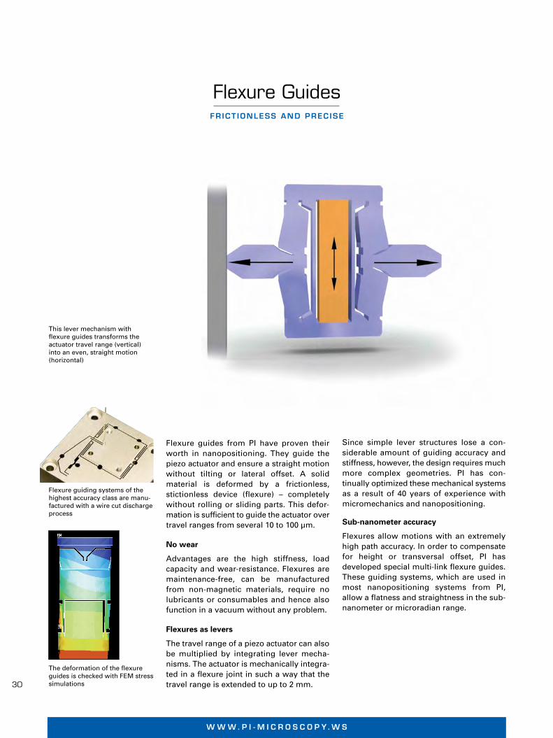
Flexure guides from PI have proven theirworth in nanopositioning. They guide thepiezo actuator and ensure a straight motionwithout tilting or lateral offset. A solid material is deformed by a frictionless, stictionless device (flexure) – completely with out rolling or sliding parts. This defor-mation is sufficient to guide the actuator overtravel ranges from several 10 to 100 µm.
No wear
Advantages are the high stiffness, load capacity and wear-resistance. Flexures aremaintenance-free, can be manufacturedfrom non-magnetic materials, require no lubricants or consumables and hence alsofunction in a vacuum without any problem.
Flexures as levers
The travel range of a piezo actuator can alsobe multiplied by integrating lever mecha-nisms. The actuator is mechanically integra-ted in a flexure joint in such a way that thetravel range is extended to up to 2 mm.
Since simple lever structures lose a con-siderable amount of guiding accuracy andstiffness, however, the design requires muchmore complex geometries. PI has con-tinually optimized these mechanical systemsas a result of 40 years of experience with micromechanics and nanopositioning.
Sub-nanometer accuracy
Flexures allow motions with an extremelyhigh path accuracy. In order to compensatefor height or transversal offset, PI has developed special multi-link flexure guides.These guiding systems, which are used inmost nanopositioning systems from PI,allow a flatness and straightness in the sub-nanometer or microradian range.
The deformation of the flexureguides is checked with FEM stresssimulations
This lever mechanism with flexure guides transforms theactuator travel range (vertical)into an even, straight motion (horizontal)
Flexure guiding systems of thehighest accuracy class are manu-factured with a wire cut dischargeprocess©
Ph
ysik
Inst
rum
ente
(P
I) G
mb
H &
Co
. KG
201
1. S
ub
ject
to
ch
ang
e w
ith
ou
t n
oti
ce. L
ates
t re
leas
es a
vaila
ble
at
ww
w.p
i.ws.
11/
10/2
6.0
TEC04_Datasheet_Layout 3 26.03.12 11:48 Seite 1
31
PI (Physik Instrumente) is the leading supplier of piezo-based positioning systems with accu-racies in the range of a few nanometers.
The extensive product portfolio is based on a
wide range of technologies with electromotive
or piezoelectric drives for up to six motion axes.
Hexapods, nanometer sensors, control electro-
nics as well as software and are supplemented
by customized solutions.
All key technologies are developed in-house.
This means that every phase from the design
right down to the shipment can be controlled:
The precision mechanics and the electronics as
well as the position sensors and the piezo cera-
mics or actuators. The latter are produced by
the subsidiary company PI Ceramic.
PI is, therefore, the only manufacturer of nano-
positioning technology which employs the pie-
zoelectric drives it produces. This ensures a
high degree of flexibility for developing custo-
mized piezoceramic components.
More than 100 patents and patents applied for stand for more than 40 years of experience and pioneering work. PI products are employed wherever technology in industry and research is pushed forward – worldwide.
With four German factories and ten subsidiaries and sales offices abroad, the PI group is repre-sented internationally.
PI stands for quality in products, processes and service. The ISO-9001 certification which focu-ses not only on product quality but also on customer expectations and satisfaction was achieved back in 1994.
PI is also certified according to the ISO 14001 (environmental management) and OHSAS 18001 (occupational safety) standards, which taken together form an Integrated Management System (IMS).
Future Technology Solutions
Today PI delivers micro- and nanopositioning solutions for all important high-tech markets:
n Semiconductor technology
n Optical metrology, microscopy
n Biotechnology and medical devices
n Precision automation and handling
n Precision machining
n Data storage technology
n Photonics, telecommunications
n Nanotechnology
n Micropositioning
n Aerospace engineering
n Astronomy
PREC IS ION POS IT ION ING FOR SC IENCE AND INDUSTRY
PI: Drives that Set the World in Motion

W W W . P i - m i c r o s c o P Y . W s
Program Overview
� Piezo Ceramic Actuators & Motors
� Piezo Nanopositioning Systems & Scanners
� Active Optics / Tip-Tilt Platforms
� Capacitive Nanometrology Sensors
� Piezo Electronics: Amplifiers and Controllers
� Hexapod 6-Axis Positioners / Parallel Kinematics
� Photonics Alignment Systems, Solutions for Telecommunications
� Ultrasonic Linear Motors
PI General Catalog
Request it now!
Vorspannseiten_Layout 1 13.04.12 09:42 Seite 6
W W W. P I . W S
P I E Z O N A N O P O S I T I O N I N G
JAPAN
PI Japan Co., Ltd.Tachikawa Business Center Bldg. 5F2-38-5 Akebono-choTachikawa-shi, Tokyo 190-0012Tel. +81 (42) 526 7300Fax +81 (42) 526 [email protected]
PI Japan Co., Ltd.Hanahara Daini Bldg. #7034-11-27 NishinakajimaYodogawa-ku, Osaka-shiOsaka 532-0011Tel. +81 (6) 6304 5605Fax +81 (6) 6304 [email protected]
ITALY
Physik Instrumente (PI) S. r. l.Via G. Marconi, 2820091 Bresso (MI)Tel. +39 (02) 665 011 01Fax +39 (02) 610 396 [email protected]
CHINA
Physik Instrumente (PI Shanghai) Co., Ltd.Building No. 7-106Longdong Avenue 3000201203 Shanghai, ChinaTel. +86 (21) 518 792 98Fax +86 (21) 687 900 [email protected]
UK & IRELAND
PI (Physik Instrumente) Ltd.Trent House, University Way,Cranfield Technology Park,Cranfield, Bedford MK43 0ANTel. +44 (1234) 756 360Fax +44 (1234) 756 [email protected]
FRANCE
PI France S.A.S.244 bis, avenue Marx Dormoy92120 MontrougeTel. +33 (1) 55 22 60 00Fax +33 (1) 41 48 56 [email protected]
SubsidiariesUSA (East) & CANADA USA (West) & MEXIKO
PI (Physik Instrumente) L.P.16 Albert St.Auburn, MA 01501Tel. +1 (508) 832 3456Fax +1 (508) 832 [email protected]
PI (Physik Instrumente) L.P.5420 Trabuco Rd., Suite 100Irvine, CA 92620Tel. +1 (949) 679 9191Fax +1 (949) 679 [email protected]
SOUTH EAST ASIA
PI (Physik Instrumente) Singapore LLP20 Sin Ming Lane #05-60 Midview CitySingapore 573968 Tel. +65 665 98400Fax +65 665 [email protected] ID / MY / PH / SG / TH
KOREA
PI Korea Ltd.6F Jeongu Bldg.Cheonho-Daero 1111Gangdong-gu138-814 SeoulTel. +82 2475 0060Fax +82 2475 [email protected]
HeadquartersGERMANY
Physik Instrumente (PI)GmbH & Co. KGAuf der Roemerstr. 176228 Karlsruhe/PalmbachTel. +49 (721) 4846-0Fax +49 (721) [email protected]
PI miCos GmbHEschbach [email protected]
PI Ceramic [email protected]
pi_rueckseite_e_A4.indd 1 23.01.12 11:24
BR
O28
E P
I Pro
du
cts
for
Mic
rosc
op
y 12
/04/
16.0
,2; S
ub
ject
to
ch
ang
e w
ith
ou
t n
oti
ce ©
Ph
ysik
Inst
rum
ente
(P
I) G
mb
H &
Co
. KG
201
2