Embed Size (px)
Citation preview
FASTCAM-512PCI
Hardware Manual
Rev.1.06E

The copyright of this manual is held by PHOTRON LIMITED.
Product specifications and manual contents are subject to change without notice.
PHOTRON LIMITED bears no responsibility for any results by using our products nor by applying this manual to any operations.
FASTCAM-512PCI Hardware Manual
Preface
Thank you for your purchase of Photron’s high-speed camera system, the “FASTCAM-
512PCI”.
This manual contains the operating instructions and warnings necessary for using the
system. Before using the system, please read the entire manual.
If any part of this manual is unclear, contact Photron using the contact information
printed at the back of the manual.
After you finish reading the manual, store it in a safe place along with the warranty card
and refer back to it when necessary.
The FASTCAM-512PCI High-Speed Video Camera System will prove itself a truly
powerful imaging tool, providing solutions for engineers and scientists in such fields as
general research and development, designing, manufacturing, quality assurance,
scientific researches, medical and biological researches, and space and aeronautical
engineering. The FASTCAM-512PCI seamlessly connects to a PC, becoming an
integral part of the computer, and when combined with it’s easy-to-use control software
provides an image recording and processing system for analyzing captured fast moving
or high-speed events immediately, a task which has often proven difficult with
conventional video systems.
You will find this new recording technology most useful to capture images of high-speed
subjects for subsequent slow-motion observation, motion analysis, and image
processing applications. This manual presents the technical details of the
FASTCAM-512PCI system and how to operate it.
Remarks: 1. For the best use of the FASTCAM-512PCI, please read through this manual.
2. The content of this manual is based on the best knowledge of the manufacturer.
However, in case any error or missed information is found in this manual, please
inform the manufacturer of such shortcomings immediately. Notwithstanding the
above, the manufacturer is not responsible for any results of the use of this
equipment.
3. Copying all or any part of this manual without permission is prohibited.
4. The content of this manual may be changed any time without prior notice.
5. The manufacturer assumes no responsibility for any direct or indirect damages or
loss of profit resulting from the use of this equipment
6. The manufacturer assumes no responsibility for any result of the use of this
equipment.
7. Copying all or any part of the software included in this system without prior written
permission by the author is an infringement of copyright.
FASTCAM-512PCI Hardware Manual
Using the System Safely and Correctly
In order to prevent injury to yourself and others, and to prevent damage to property,
carefully observe the following safety precautions.
Photron has given its full attention to the safety of this system. However, the extent of
damage and injury potentially caused by ignoring the content of the safety precautions
and using the system incorrectly is explained next. Please pay careful attention to the
content of the safety precautions when using the system.
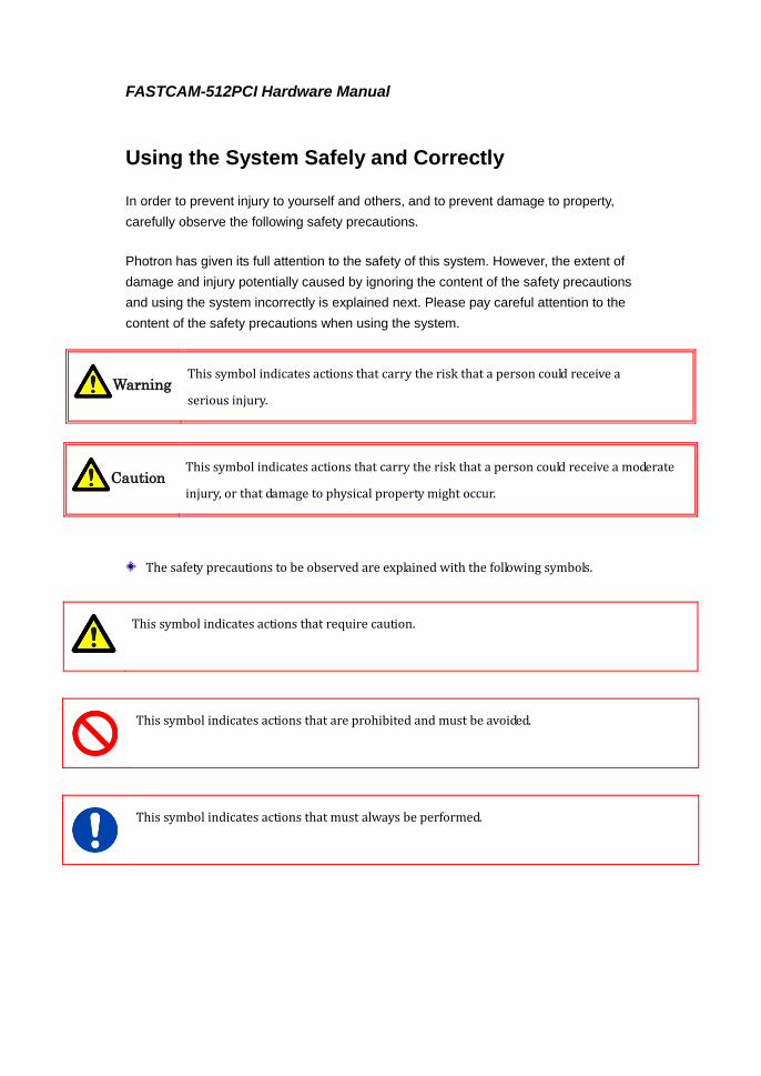
This symbol indicates actions that carry the risk that a person could receive a
serious injury.
This symbol indicates actions that carry the risk that a person could receive a moderate
injury, or that damage to physical property might occur.
The safety precautions to be observed are explained with the following symbols.
This symbol indicates actions that require caution.
This symbol indicates actions that are prohibited and must be avoided.
This symbol indicates actions that must always be performed.
Caution
Warning
FASTCAM-512PCI Hardware Manual
■ Do not insert metallic objects inside, or pour liquids such as water on, the system.
Doing so can cause fire, electric shock, or malfunction from short circuit or heat.
■ Do not disassemble or modify the system.
There are high voltages inside the system that can cause electric shock.
Warning

FASTCAM-512PCI Hardware Manual
■ Do not set the system in a location where the temperature gets unusually hot.
trunk and inside of a car can get especially hot in summer.
Doing so can cause the outer case and internal components to deteriorate or cause a fire.
■ Do not place the system in a location prone to oily smoke or steam, or in a location with a lot
of humidity or dust.
Oil, moisture, and dust conduct electricity, which can cause a fire or electric shock.
■ Ambient temperature 0-40° C, humidity 85% RH or lower, maximum altitude 2,000m or lower.
In addition, if exceeding these limits, use in a condensation-free environment.
Doing so can cause malfunction.
■ Do not store the equipment in a location where the temperature goes below -20°C or higher
than 60°C.
Also, prevent condensation from forming during shipment
■ This device is for indoor use, do not use it outdoors.
Do not use in a location that has dust.
Doing so can cause malfunction.
■ When shipping, remove the connecting cable and use the original packaging or a dedicated
carrying case.
Do not ship the equipment in an environment where the temperature goes below
0°C or higher than 40°C. Also, prevent condensation from forming during shipment
Caution
FASTCAM-512PCI Hardware Manual
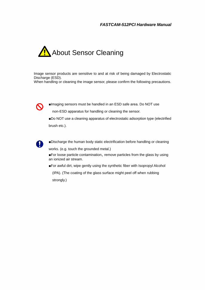
Image sensor products are sensitive to and at risk of being damaged by Electrostatic Discharge (ESD). When handling or cleaning the image sensor, please confirm the following precautions.
■Imaging sensors must be handled in an ESD safe area. Do NOT use
non-ESD apparatus for handling or cleaning the sensor.
■Do NOT use a cleaning apparatus of electrostatic adsorption type (electrified
brush etc.).
■Discharge the human body static electrification before handling or cleaning
works. (e.g. touch the grounded metal.)
■For loose particle contamination, remove particles from the glass by using
an ionized air stream.
■For awful dirt, wipe gently using the synthetic fiber with Isopropyl Alcohol
(IPA). (The coating of the glass surface might peel off when rubbing
strongly.)
About Sensor Cleaning

FASTCAM-512PCI Hardware Manual
Table of contents Chapter 1. Set Up ................................................................................... 1
1.1. About the System’s Components and Accessories .......................................... 2 1.1.1. Unpacking ................................................................................................. 2
1.2. About the Camera ......................................................................................... 3 1.2.1. Grabber Board ........................................................................................... 3 1.2.2. Camera Head and Camera Cable ............................................................. 4 1.2.3. Accessories ................................................................................................. 5 1.2.4. Connector Specifications ........................................................................... 6
1.3. Installation of Hardware ............................................................................... 9 1.3.1. Installing Grabber Board in PC ............................................................... 9
1.4. Setup for Multiple-Camera Recording ......................................................... 11 1.4.1. Master/Slave Mode Setup ....................................................................... 12 1.4.2. Connection of Multiple Cameras ............................................................ 13 1.4.3. Setting Up Camera ID Numbers ............................................................ 17 1.4.4. Setting Up Software ................................................................................ 18 1.4.5. Tips on Multiple-Camera Sync Recording ............................................. 22
1.5. Random Reset Trigger Mode ....................................................................... 23 Chapter 2 Appendix ........................................................................... 25
2.1. Specifications .............................................................................................. 26 2.1.1. Basic Specifications ................................................................................. 26 2.1.2. Specifications – Recording System ......................................................... 27 2.1.3. Other Specifications ................................................................................ 28 2.1.4. Frame Rate vs. Image Resolution .......................................................... 29 2.1.5 Frame Rate and Image Size .................................................................... 30 2.1.6. Resolution and Shutter Speed ................................................................ 31 2.1.7. Frame Rate vs. Number of Recorded Frames and Record Duration .... 32
2.2. Dimensions .................................................................................................. 37 2.2.1. Camera Head (Millimeters) .................................................................... 37 2.2.2. Grabber Board (Millimeters) .................................................................. 38
2.3. Timing of Recording Operations .................................................................. 39 2.3.1 Timing Charts for Recording Operations ................................................ 39 2.3.2. Sync Timing in Multi-Camera Operations ............................................. 43 2.3.3. Delay of Vertical Sync and Trigger Signals in Multiple-Camera Operation ...... 43 2.3.4 Recording Interval in Random Center and Random Manual Trigger Modes ..... 44
Chapter 3 Contacting Photron ............................................................. 45 3.1 Contact Information ..................................................................................... 46
FASTCAM-512PCI Hardware Manual
- 1 -
Chapter 1. Set Up
1.1. About the System’s Components and Accessories
1.2. About the Camera
1.3. Installation of Hardware
1.4. Setup for Multiple Camera Recording
1.5. Random Reset Trigger Mode

FASTCAM-512PCI Hardware Manual
- 2 -
1.1. About the System’s
Components and Accessories
1.1.1. Unpacking Refer to the attached packing list for this product's standard components and accessories.

FASTCAM-512PCI Hardware Manual
- 3 -
1.2. About the Camera The FASTCAM-512PCI consists of a grabber board (PCI Board), a camera head and a control software program set.
For each of the system components. - Do not expose to shock outside. - Do not use in an area with flammable gas or dust present. - Do not place in an unstable location such as on an unstable platform or an incline. - Do not disassemble or modify. - Do not expose to liquids such as water. - Do not subject to excessive force.
1.2.1. Grabber Board The grabber board of the FASTCAM-512PCI has been designed so that up to four FASTCAM-512PCI boards can be installed in ATX standard PCI slots of a PC. Note: When you are installing four grabber boards in one PC, the PCI slot right next to the graphics slot in the PC becomes unusable. This means the PC must have five or more PCI slots in it to accommodate four grabber boards.
LED
1234
DIP SWDIP SWCamera Connector
Guide Plate
Retaining Plate PCI Card Bus Edge
EXT IN Connector
EXT OUT Connector
EXT OUT
EXT IN
FASTCAM-512PCI Hardware Manual
- 4 -
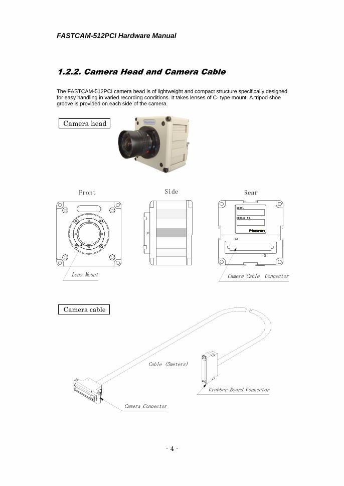
1.2.2. Camera Head and Camera Cable
The FASTCAM-512PCI camera head is of lightweight and compact structure specifically designed for easy handling in varied recording conditions. It takes lenses of C- type mount. A tripod shoe groove is provided on each side of the camera.
Camera Connector
Grabber Board Connector
Cable (5meters)
SERIAL NO.
MODEL
Front Side Rear
Camere Cable ConnectorLens Mount
Camera head
Camera cable

FASTCAM-512PCI Hardware Manual
- 5 -
1.2.3. Accessories EXT OUT/ EXT IN Cables The Grabber Board has two compound connectors to connect it to external equipment and devices via cables to receive and send out signals such as external trigger and sync signals. Two compound cables are included in the package as shown below.
T-TTL IN
SYNC IN
T-SW IN
Relay Adapter
Relay AdapterSYNC OUT
GENE OUT
TRI OUT
FASTCAM-512PCI Hardware Manual
- 6 -
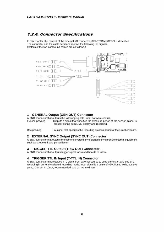
1.2.4. Connector Specifications In this chapter, the content of the external I/O connector of FASTCAM-512PCI is describes. The connector and the cable send and receive the following I/O signals. (Details of the two compound cables are as follows.)
1 GENERAL Output (GEN OUT) Connector A BNC connector that outputs the following signals under software control. Expose pos/neg : Outputs a signal that specifies the exposure period of the sensor. Signal is
present during both LIVE display and recording.
Rec pos/neg :A signal that specifies the recording process period of the Grabber Board.
2 EXTERNAL SYNC Output (SYNC OUT) Connector A BNC connector that outputs the camera’s vertical sync signal to synchronize external equipment such as strobe unit and pulsed laser.
3 TRIGGER TTL Output (TRIG OUT) Connector A BNC connector that outputs trigger signal for slaved boards to follow.
4 TRIGGER TTL IN Input (T-TTL IN) Connector A BNC connector that receives TTL signal from external source to control the start and end of a recording in currently selected recording mode. Input signal is a pulse of +5V, 5µsec wide, positive going. Current is 10mA, recommended, and 20mA maximum.
GEN OUT
T-SW IN
SYNC IN
T-TTL IN
TRIG OUT
SYNC OUT
EXT IN
EXT OUT
EXT OUT
EXT IN

FASTCAM-512PCI Hardware Manual
- 7 -
5 TRIGGER SW IN Input (T-SW IN) Connector A BNC connector whose co-axial cable shield and center conductors are used to send contact closure signals to control the start and end of a recording in currently selected recording mode. To avoid possible damage to the camera system, do NOT input signals other than contact closure to T-SW IN connector.
6 EXTERNAL SYNC Input (SYNC IN) Connector A BNC connector that receives sync signal from master board or external equipment.
FASTCAM-512PCI Hardware Manual
- 8 -
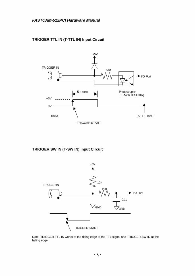
TRIGGER TTL IN (T-TTL IN) Input Circuit
TRIGGER SW IN (T-SW IN) Input Circuit
Note: TRIGGER TTL IN works at the rising edge of the TTL signal and TRIGGER SW IN at the falling edge.
TRIGGER IN
TRIGGER START
5V TTL level
Photocoupler TLP521(TOSHIBA)
I/O Port
330
+5V
+5V
0V
10mA
5μ sec以上
TRIGGER IN
TRIGGER START
220
I/O Port
GND
10K
+5V
GND
0.1μ
5μsec

FASTCAM-512PCI Hardware Manual
- 9 -
1.3. Installation of Hardware Turn off the computer and unplug the power cord from power outlet before connecting between the camera head and Grabber Board, and installing the Grabber Board in the PC to avoid electrical shock and possible damage to the system and/or components. Remove the cable twist-ties before connecting.
1.3.1. Installing Grabber Board in PC Follow the procedure below to install the Grabber Board in the PC: 1. Turn off the PC and unplug the power cable. 2. Remove covers of the PC following the PC’s instruction manual. 3. Make sure there are unused PCI slot(s). 4. Remove the metal cover plate in the back of the unused PCI slot where you wish to install the
Grabber Board. 5. Insert the Grabber Board into the unused PCI slot. Firmly press the edge of the Grabber
Board so the connector engages perfectly. Fasten the board with retaining screws. Insert squarely into PCI slot. Fasten with screws. The position of the guide plate on the end of the Grabber Board can be readjusted by the retaining screws. See the board guide on the PC to check for the best position for the guide plate. Grabber Board firmly inserted
along the board guide.
Guide Plate and its
retaining screws
FASTCAM-512PCI Hardware Manual
- 10 -
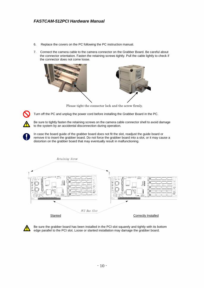
6. Replace the covers on the PC following the PC instruction manual.
7. Connect the camera cable to the camera connector on the Grabber Board. Be careful about
the connector orientation. Fasten the retaining screws tightly. Pull the cable lightly to check if the connector does not come loose.
Turn off the PC and unplug the power cord before installing the Grabber Board in the PC.
Be sure to tightly fasten the retaining screws on the camera cable connector shell to avoid damage to the system by an accidental disconnection during operation.
In case the board guide of the grabber board does not fit the slot, readjust the guide board or remove it to insert the grabber board. Do not force the grabber board into a slot, or it may cause a distortion on the grabber board that may eventually result in malfunctioning.
Slanted Correctly Installed
Be sure the grabber board has been installed in the PCI slot squarely and tightly with its bottom edge parallel to the PCI slot. Loose or slanted installation may damage the grabber board.
Retaining Screw
PCI Bus Slot
Please tight the connector lock and the screw firmly.

FASTCAM-512PCI Hardware Manual
- 11 -
1.4. Setup for Multiple-Camera Recording
The FASTCAM-512PCI is capable of multiple camera operation: up to four cameras can be connected to a single PC. It also supports synchronized recording by sync signal supplied from external equipment (signal generator, etc.). In multiple camera operation, the cameras record a common subject from different perspectives along a shared timeline. This capability can also be used to record images of a fast-moving subject, together with other subjects related to it, from different viewpoints simultaneously. This section describes how to set up the FASTCAM-512PCI for multiple camera operation. Multiple camera operation requires the following setups.
1.4.1. Master/Slave Mode Setup 1.4.2. Connection of Multiple Cameras 1.4.3. Setting up ID Numbers 1.4.4. Setting up Software 1.4.5. Tips on Multiple-Camera Sync Recording
FASTCAM-512PCI Hardware Manual
- 12 -
1 2 3 4 O N
ディップスイッチ
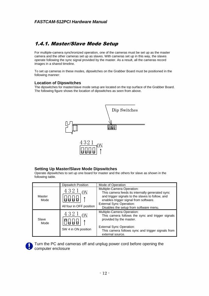
1.4.1. Master/Slave Mode Setup For multiple-camera synchronized operation, one of the cameras must be set up as the master camera and the other cameras set up as slaves. With cameras set up in this way, the slaves operate following the sync signal provided by the master. As a result, all the cameras record images in a shared timeline. To set up cameras in these modes, dipswitches on the Grabber Board must be positioned in the following manner:
Location of Dipswitches The dipswitches for master/slave mode setup are located on the top surface of the Grabber Board. The following figure shows the location of dipswitches as seen from above.
Setting Up Master/Slave Mode Dipswitches Operate dipswitches to set up one board for master and the others for slave as shown in the following table.
Dipswitch Position Mode of Operation
Master Mode
1 2 3 4 O N
All four in OFF position
Multiple-Camera Operation: This camera feeds its internally generated sync and trigger signals to the slaves to follow, and enables trigger signal from software.
External Sync Operation: Disables the setup from software menu.
Slave Mode
1 2 3 4 O N
SW 4 in ON position
Multiple-Camera Operation: This camera follows the sync and trigger signals provided by the master.
External Sync Operation:
This camera follows sync and trigger signals from external source.
Turn the PC and cameras off and unplug power cord before opening the computer enclosure
Dip Switches

FASTCAM-512PCI Hardware Manual
- 13 -
1.4.2. Connection of Multiple Cameras After master/slave camera setup, connect sync cables between boards as described in the following subsections:
Details of Connectors
1. GENERAL Output (GEN OUT) Connector
2. EXTERNAL SYNC Output (SYNC OUT) Connector
3. TRIGGER TTL Output (TRIG OUT) Connector
4. TRIGGER TTL IN Input (T-TTL IN) Connector
5. TRIGGER SW IN Input (T-SW IN) Connector
6. EXTERNAL SYNC Input (SYNC IN) Connector
GEN OUT
T-SW IN
SYNC IN
T-TTL IN
TRIG OUT
SYNC OUT
EXT IN
EXT OUT
FASTCAM-512PCI Hardware Manual
- 14 -
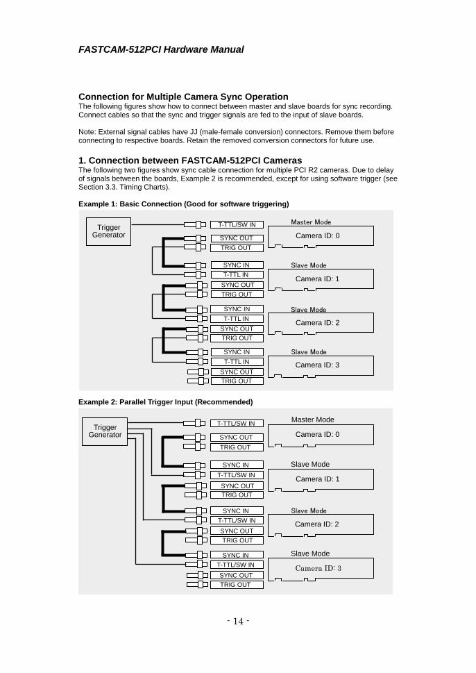
Connection for Multiple Camera Sync Operation The following figures show how to connect between master and slave boards for sync recording. Connect cables so that the sync and trigger signals are fed to the input of slave boards. Note: External signal cables have JJ (male-female conversion) connectors. Remove them before connecting to respective boards. Retain the removed conversion connectors for future use.
1. Connection between FASTCAM-512PCI Cameras The following two figures show sync cable connection for multiple PCI R2 cameras. Due to delay of signals between the boards, Example 2 is recommended, except for using software trigger (see Section 3.3. Timing Charts). Example 1: Basic Connection (Good for software triggering)
Master Mode
Slave Mode
Slave Mode
Slave Mode
Camera ID: 0
Camera ID: 1
Camera ID: 2
Camera ID: 3
SYNC IN
SYNC OUT
TRIG OUT
T-TTL IN
SYNC OUT
TRIG OUT
SYNC IN
SYNC OUT
TRIG OUT
T-TTL IN
SYNC IN
SYNC OUT
TRIG OUT
T-TTL IN
T-TTL/SW IN
Trigger Generator
Master Mode
Slave Mode
Slave Mode
Slave Mode
Camera ID: 0
Camera ID: 1
Camera ID: 2
Camera ID: 3
SYNC IN
SYNC OUT
TRIG OUT
T-TTL/SW IN
SYNC OUT
TRIG OUT
SYNC IN
SYNC OUT
TRIG OUT
T-TTL/SW IN
SYNC IN
SYNC OUT
TRIG OUT
T-TTL/SW IN
T-TTL/SW IN
Example 2: Parallel Trigger Input (Recommended)
Trigger Generator

FASTCAM-512PCI Hardware Manual
- 15 -
2. Using External Sync Generator The figure below shows an example of connection using an external sync generator. To avoid any possible delay of sync and trigger signals between boards, this connection is highly recommended, unless using software triggering (see Subsection 3.3. Timing Charts).
(The connection of SYNC OUT → SYNC IN and TRIG OUT → T-TTL IN is not recommended for
the above-mentioned reason though operates either.) Recommended Connection
The characteristic of the circuit configuration inside the 512PCI camera inevitably causes a slight
error of ±22.98 nsec against the input sync signal.
Example: For 10,000 Hz input sync signal, the actual frame rate in each camera is:
100 usec±22.98 nsec = 9,998 fps to 10,002 fps
SYNC IN
T-TTL/SW IN
External Sync Mode
SYNC OUT
TRIG OUT
SYNC IN
T-TTL/SW IN
External Sync Mode
SYNC OUT
TRIG OUT
SYNC IN
T-TTL/SW IN
External Sync Mode
SYNC OUT
TRIG OUT
SYNC IN
T-TTL/SW IN
External Sync
SYNC OUT
TRIG OUT
External Signal
Generator
Sync Signal Trigger Signal
Camera ID: 0
Camera ID: 1
Camera ID: 2
Camera ID: 3
Trigger Generator
External Signal
FASTCAM-512PCI Hardware Manual
- 16 -
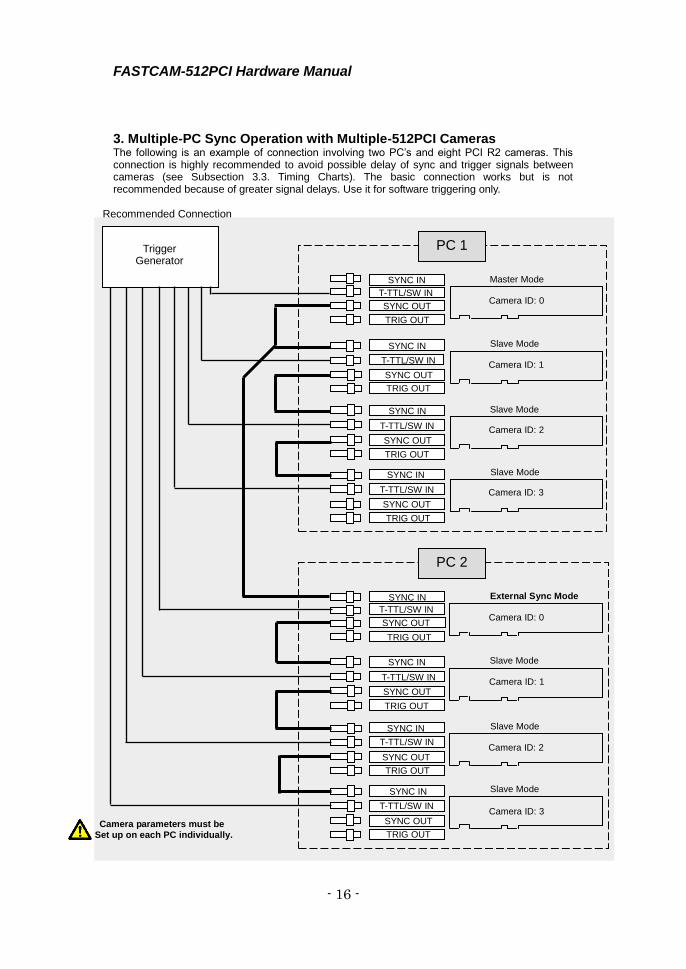
3. Multiple-PC Sync Operation with Multiple-512PCI Cameras The following is an example of connection involving two PC’s and eight PCI R2 cameras. This connection is highly recommended to avoid possible delay of sync and trigger signals between cameras (see Subsection 3.3. Timing Charts). The basic connection works but is not recommended because of greater signal delays. Use it for software triggering only.
Trigger
Generator
PC 1
PC 2
Master Mode
Slave Mode
Slave Mode
Slave Mode
Camera ID: 0
Camera ID: 1
Camera ID: 2
Camera ID: 3
SYNC IN
SYNC OUT
TRIG OUT
T-TTL/SW IN
SYNC OUT
TRIG OUT
SYNC IN
SYNC OUT
TRIG OUT
T-TTL/SW IN
SYNC IN
SYNC OUT
TRIG OUT
T-TTL/SW IN
T-TTL/SW IN
SYNC IN
External Sync Mode
Slave Mode
Slave Mode
Slave Mode
Camera ID: 0
Camera ID: 1
Camera ID: 2
Camera ID: 3
SYNC IN NC IN
SYNC OUT TRIG OUT
T-TTL/SW IN
SYNC OUT
TRIG OUT
SYNC IN
SYNC OUT
TRIG OUT
T-TTL/SW IN
SYNC IN
SYNC OUT TRIG OUT
T-TTL/SW IN
T-TTL/SW IN
SYNC IN
Recommended Connection
Camera parameters must be Set up on each PC individually.

FASTCAM-512PCI Hardware Manual
- 17 -
1.4.3. Setting Up Camera ID Numbers For the software to recognize each camera involved in a multiple-camera operation, an ID number, from 0 to 3, is assigned to each camera. With this ID number, each camera is correctly recognized by the system even if the order of recognition is changed. The following shows how to assign ID numbers to cameras used in a multiple camera system.
Dipswitch Operation to Set Up Camera ID Numbers Camera ID numbers 1 to 4 are defined by the ON/OFF position of dipswitches 1, 2 and 3 as shown below.
ID No. Dipswitches SW 3 SW 2 SW 1
0 1 2 3 4 O N
OFF OFF OFF
1 1 2 3 4 O N
OFF OFF ON
2 1 2 3 4 O N
OFF ON OFF
3 1 2 3 4 O N
OFF ON ON
The factory-set ID is 0. Assign ID No. 1 to the master board (or the board that receives sync signal from an external source), and other numbers to the slaves in the order of PCI slots in the computer chassis. Do not duplicate an ID number within a multiple-camera system.
FASTCAM-512PCI Hardware Manual
- 18 -
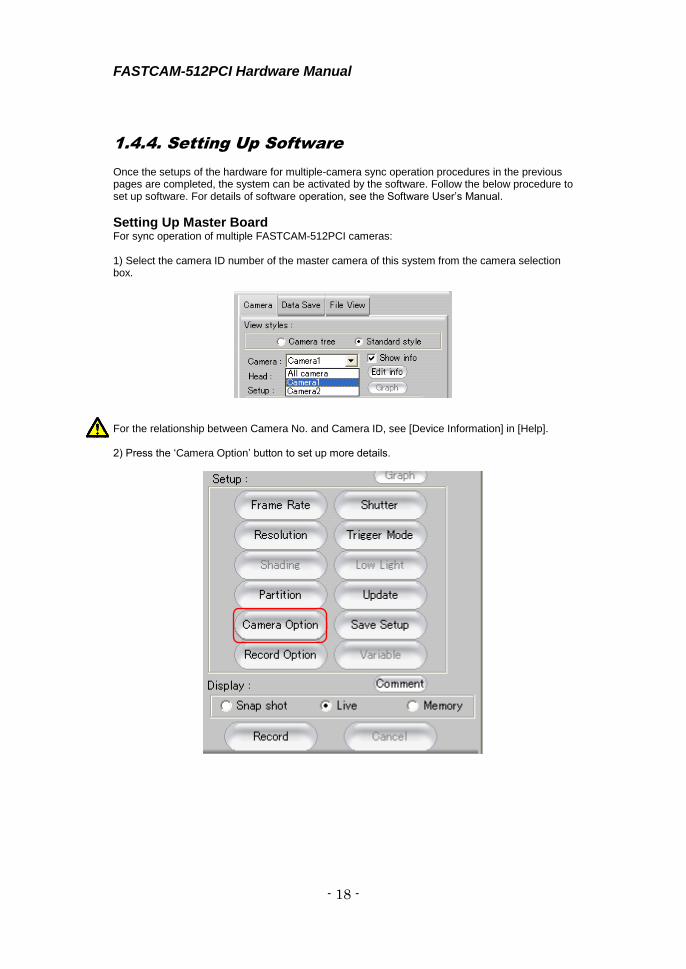
1.4.4. Setting Up Software Once the setups of the hardware for multiple-camera sync operation procedures in the previous pages are completed, the system can be activated by the software. Follow the below procedure to set up software. For details of software operation, see the Software User’s Manual.
Setting Up Master Board For sync operation of multiple FASTCAM-512PCI cameras: 1) Select the camera ID number of the master camera of this system from the camera selection box.
For the relationship between Camera No. and Camera ID, see [Device Information] in [Help]. 2) Press the ‘Camera Option’ button to set up more details.
FASTCAM-512PCI Hardware Manual
- 19 -
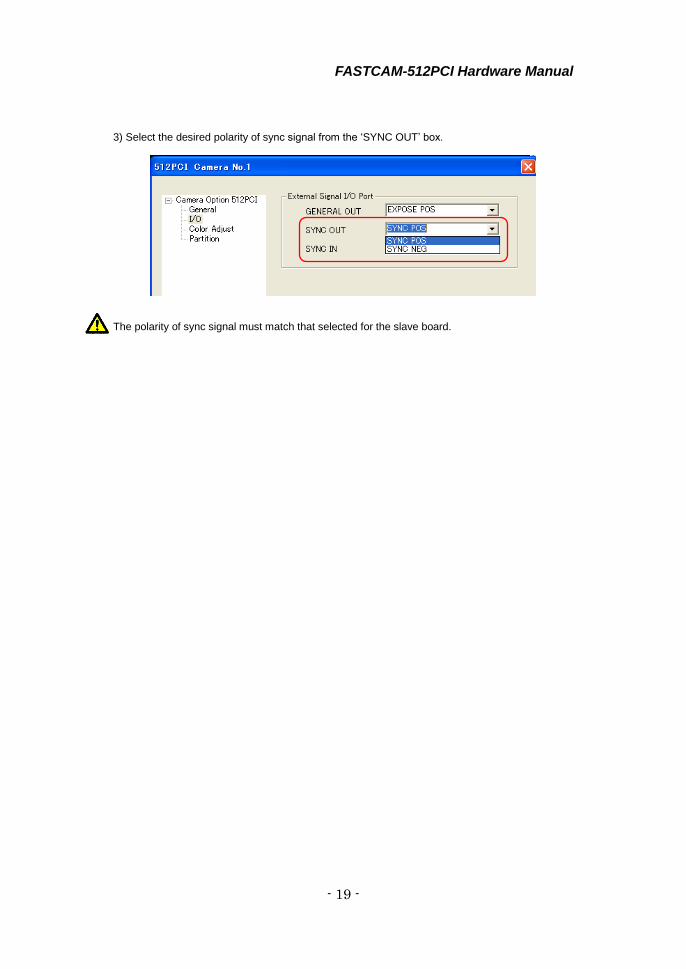
3) Select the desired polarity of sync signal from the ‘SYNC OUT’ box.
The polarity of sync signal must match that selected for the slave board.
FASTCAM-512PCI Hardware Manual
- 20 -
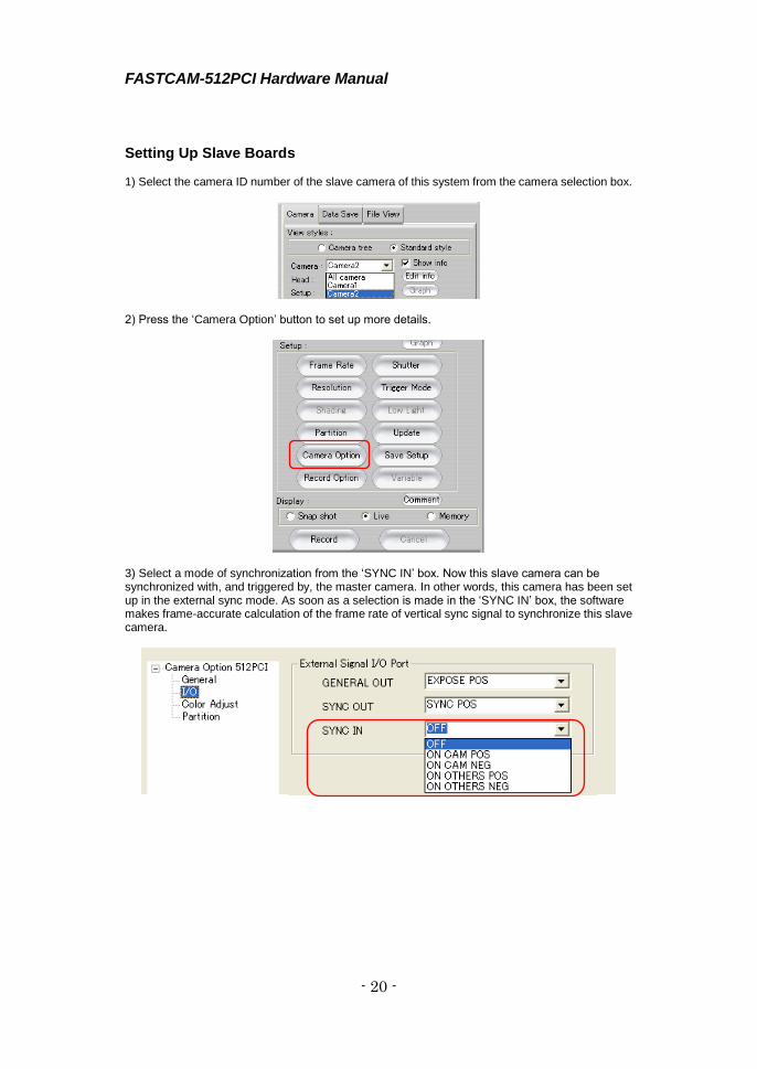
Setting Up Slave Boards 1) Select the camera ID number of the slave camera of this system from the camera selection box.
2) Press the ‘Camera Option’ button to set up more details.
3) Select a mode of synchronization from the ‘SYNC IN’ box. Now this slave camera can be synchronized with, and triggered by, the master camera. In other words, this camera has been set up in the external sync mode. As soon as a selection is made in the ‘SYNC IN’ box, the software makes frame-accurate calculation of the frame rate of vertical sync signal to synchronize this slave camera.

FASTCAM-512PCI Hardware Manual
- 21 -
Items to choose from in the ‘SYNC IN’ box:
OFF Disable Voids external sync.
ON CAM POS Normal Modes
Sync operation of multiple 512PCI cameras ON CAM NEG
ON OTHERS POS External Sync Modes
Sync operation of multiple 512PCI cameras with external sync signal. Or, sync operation of multiple 512PCI cameras with multiple PC’s.
ON OTHERS NEG
The SYNC IN window for the master camera is turned gray and no selection can be made. The polarity must match that selected in the ‘SYNC OUT’ box of the master camera or that of the sync signal from the external source being used. 4) When more than one slave cameras are involved, each of them must be individually set up.
How External Sync Signal Mode Works? External Sync Signal Mode works as follows (See 2.4.1.): 1. As soon as either the ‘ON OTHERS POS’ or ‘ON OTHERS NEG’ synchronization mode is selected in the ‘SYNC IN’ box for a slave camera, this camera can be synchronized with and triggered by the master camera. In other words, this camera has been set up for external sync mode operation. 2. As a selection is made in the ‘SYNC IN‘ box, the software makes frame-accurate calculations of the frame rate from the vertical sync signal being fed by the external source (master camera or external generator) to synchronize this slave camera. 3. When the vertical sync signal (frame rate) from the external source is changed, you are required to re-select mode of synchronization in the ‘SYNC IN’ box so that the software can re-calculate the frame rate for the slave camera to follow. The threshold of external vertical synchronizing signal in an external equipment synchronizing mode is up to be 32,000Hz. Due to a measuring error, it is possible to not achieve the same resolution as described in chapter 2.1.5 “Frame Rate and Image Size”.
FASTCAM-512PCI Hardware Manual
- 22 -
1.4.5. Tips on Multiple-Camera Sync Recording
Using Software Triggers The software trigger is issued only to a board set up as the master board with ID “0” that has been set up for sync operation with sync signal from external source. It is not issued to any other boards. By relaying the software trigger that is issued to the master, connecting the TRIG OUT of the master board to T-TTL IN of the first slave board and so forth (see Section 2.4.2.2. Example 1: Basic Connection), multiple-camera triggering is attained without delays caused within the PCI bus. Despite the above, however, a slight delay is inevitably caused between trigger and vertical sync signals while they are forwarded from board to board. This delay may, in rare cases, result in an offset of one recorded image frame between the master and a slave camera. To avoid this delay, if necessary, use the parallel sync distribution technique shown in Section 2.4.2.2. Example 2: Parallel Trigger Input.
Using External Triggers In multiple-camera sync operation with trigger signals from an external source, the use of parallel trigger input is recommended (see Section 2.4.2.2. Example 2: Parallel Trigger Input). Relayed trigger signal (see Section 2.4.2.2. Example 1: Basic Connection) works in this operation. But, because of likely delay of relayed trigger, as is the case with the relayed software trigger described in the previous subsection, it is not recommended.

FASTCAM-512PCI Hardware Manual
- 23 -
1.5. Random Reset Trigger Mode The FASTCAM-512PCI supports the Random Reset Trigger Mode. Software set up is needed to use this mode and this section describes how to do it. Refer to the Software User’s Manual for details of software operation. 1) Press the ‘Trigger Mode’ button.
2) Select trigger mode as the ‘Random Reset’.
3) Enter the desired number of frames to record at the ‘Random frames’, and then press the
‘Close’ button.
A forced reset may cause in the first frame a brightness deviation of about 3 % from the second frame and thereafter.

FASTCAM-512PCI Hardware Manual
- 24 -
Memo
FASTCAM-512PCI Hardware Manual
- 25 -
Chapter 2 Appendix
2.1. Specifications
2.2. Dimensions
2.3. Timing Charts
FASTCAM-512PCI Hardware Manual
- 26 -
2.1. Specifications
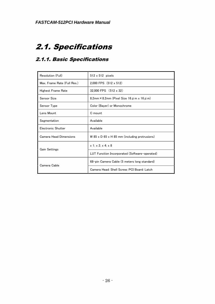
2.1.1. Basic Specifications
Resolution (Full) 512 x 512 pixels
Max. Frame Rate (Full Res.) 2,000 FPS (512 x 512)
Highest Frame Rate 32,000 FPS (512 x 32)
Sensor Size 8.2mm×8.2mm (Pixel Size 16μm x 16μm)
Sensor Type Color (Bayer) or Monochrome
Lens Mount C mount
Segmentation Available
Electronic Shutter Available
Camera Head Dimensions W 85 x D 65 x H 85 mm (including protrusions)
Gain Settings x 1; x 2; x 4; x 8
LUT Function Incorporated (Software-operated)
Camera Cable 68-pin Camera Cable (5 meters long standard)
Camera Head: Shell Screw; PCI Board: Latch
FASTCAM-512PCI Hardware Manual
- 27 -
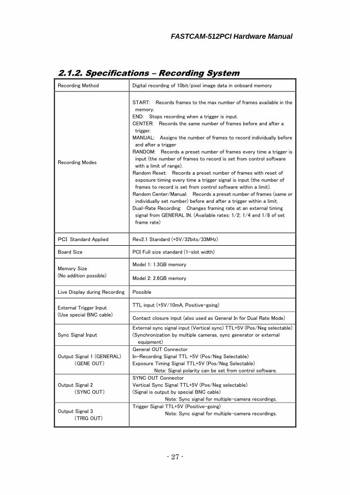
2.1.2. Specifications – Recording System
Recording Method Digital recording of 10bit/pixel image data in onboard memory
Recording Modes
START: Records frames to the max number of frames available in the
memory.
END: Stops recording when a trigger is input.
CENTER: Records the same number of frames before and after a
trigger.
MANUAL: Assigns the number of frames to record individually before
and after a trigger
RANDOM: Records a preset number of frames every time a trigger is
input (the number of frames to record is set from control software
with a limit of range).
Random Reset: Records a preset number of frames with reset of
exposure timing every time a trigger signal is input (the number of
frames to record is set from control software within a limit).
Random Center/Manual: Records a preset number of frames (same or
individually set number) before and after a trigger within a limit.
Dual-Rate Recording: Changes framing rate at an external timing
signal from GENERAL IN. (Available rates: 1/2; 1/4 and 1/8 of set
frame rate)
PCI Standard Applied Rev2.1 Standard (+5V/32bits/33MHz)
Board Size PCI Full size standard (1-slot width)
Memory Size
(No addition possible)
Model 1: 1.3GB memory
Model 2: 2.6GB memory
Live Display during Recording Possible
External Trigger Input
(Use special BNC cable)
TTL input (+5V/10mA, Positive-going)
Contact closure input (also used as General In for Dual Rate Mode)
Sync Signal Input
External sync signal input (Vertical sync) TTL+5V (Pos/Neg selectable)
(Synchronization by multiple cameras, sync generator or external
equipment)
Output Signal 1 (GENERAL)
(GENE OUT)
General OUT Connector
In-Recording Signal TTL +5V (Pos/Neg Selectable)
Exposure Timing Signal TTL+5V (Pos/Neg Selectable)
Note: Signal polarity can be set from control software.
Output Signal 2
(SYNC OUT)
SYNC OUT Connector
Vertical Sync Signal TTL+5V (Pos/Neg selectable)
(Signal is output by special BNC cable)
Note: Sync signal for multiple-camera recordings.
Output Signal 3
(TRIG OUT)
Trigger Signal TTL+5V (Positive-going)
Note: Sync signal for multiple-camera recordings.
FASTCAM-512PCI Hardware Manual
- 28 -
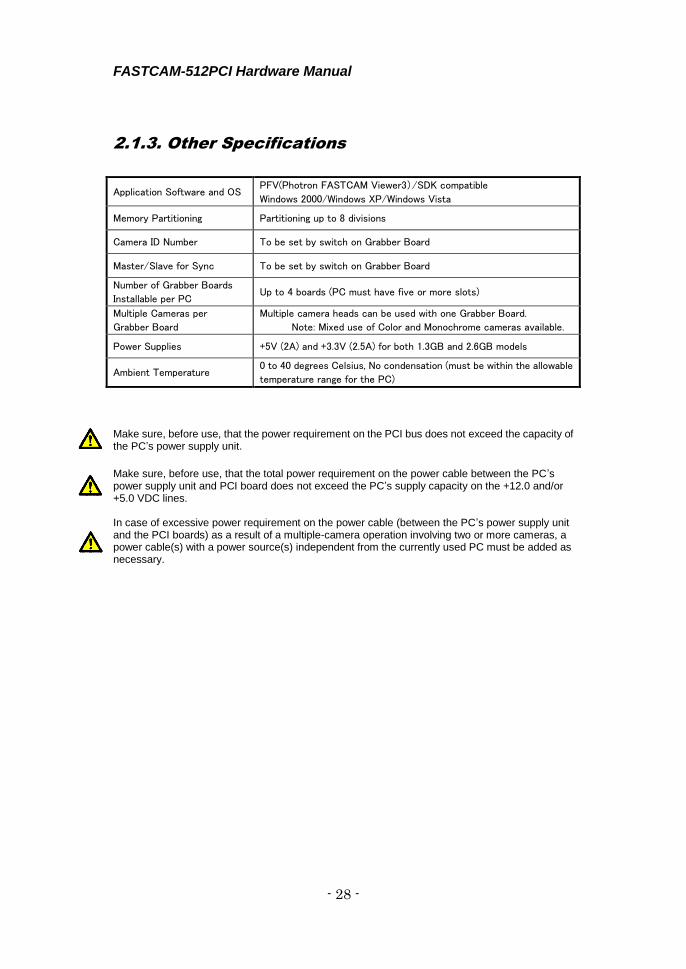
2.1.3. Other Specifications
Make sure, before use, that the power requirement on the PCI bus does not exceed the capacity of the PC’s power supply unit.
Make sure, before use, that the total power requirement on the power cable between the PC’s power supply unit and PCI board does not exceed the PC’s supply capacity on the +12.0 and/or +5.0 VDC lines. In case of excessive power requirement on the power cable (between the PC’s power supply unit and the PCI boards) as a result of a multiple-camera operation involving two or more cameras, a power cable(s) with a power source(s) independent from the currently used PC must be added as necessary.
Application Software and OS PFV(Photron FASTCAM Viewer3)/SDK compatible
Windows 2000/Windows XP/Windows Vista
Memory Partitioning Partitioning up to 8 divisions
Camera ID Number To be set by switch on Grabber Board
Master/Slave for Sync To be set by switch on Grabber Board
Number of Grabber Boards
Installable per PC Up to 4 boards (PC must have five or more slots)
Multiple Cameras per
Grabber Board
Multiple camera heads can be used with one Grabber Board.
Note: Mixed use of Color and Monochrome cameras available.
Power Supplies +5V (2A) and +3.3V (2.5A) for both 1.3GB and 2.6GB models
Ambient Temperature 0 to 40 degrees Celsius, No condensation (must be within the allowable
temperature range for the PC)
FASTCAM-512PCI Hardware Manual
- 29 -
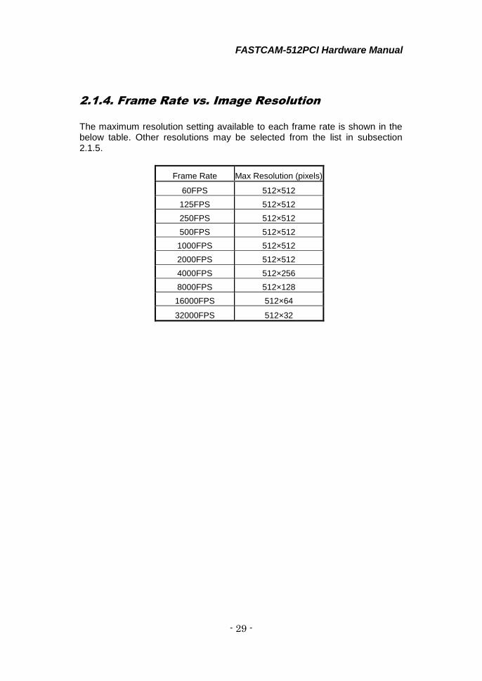
2.1.4. Frame Rate vs. Image Resolution
The maximum resolution setting available to each frame rate is shown in the below table. Other resolutions may be selected from the list in subsection 2.1.5.
Frame Rate Max Resolution (pixels)
60FPS 512×512
125FPS 512×512
250FPS 512×512
500FPS 512×512
1000FPS 512×512
2000FPS 512×512
4000FPS 512×256
8000FPS 512×128
16000FPS 512×64
32000FPS 512×32

FASTCAM-512PCI Hardware Manual
- 30 -
2.1.5 Frame Rate and Image Size
The FPS and the resolution can be arbitrarily selected according to the
following table (variable setting).
FPS Resolution
60 125 250 500 1000 2000 4000 8000 16000 32000
512×512 √ √ √ √ √ √ NA NA NA NA
512×256 √ √ √ √ √ √ √ NA NA NA
512×128 √ √ √ √ √ √ √ √ NA NA
512×64 √ √ √ √ √ √ √ √ √ NA
512×32 √ √ √ √ √ √ √ √ √ √
256×512 √ √ √ √ √ √ NA NA NA NA
256×256 √ √ √ √ √ √ √ NA NA NA
256×128 √ √ √ √ √ √ √ √ NA NA
256×64 √ √ √ √ √ √ √ √ √ NA
256×32 √ √ √ √ √ √ √ √ √ √
128×512 √ √ √ √ √ √ NA NA NA NA
128×256 √ √ √ √ √ √ √ NA NA NA
128×128 √ √ √ √ √ √ √ √ NA NA
128×64 √ √ √ √ √ √ √ √ √ NA
128×32 √ √ √ √ √ √ √ √ √ √
64×512 √ √ √ √ √ √ NA NA NA NA
64×256 √ √ √ √ √ √ √ NA NA NA
64×128 √ √ √ √ √ √ √ √ NA NA
64×64 √ √ √ √ √ √ √ √ √ NA
64×32 √ √ √ √ √ √ √ √ √ √
Please refer to the「Photron FASTCAM Viewer user manual」chapter「3.3.2
Variable Setting」for detail.

FASTCAM-512PCI Hardware Manual
- 31 -
2.1.6. Resolution and Shutter Speed
Shutter Speed Exposure (sec) Shutter Speed Exposure (sec)
1/2000 0.0005000000 1/23500 0.0000422794
1/2500 0.0003998162 1/25500 0.0000395221
1/3000 0.0003336397 1/27000 0.0000367647
1/3500 0.0002858456 1/29500 0.0000340074
1/4000 0.0002500000 1/32000 0.0000312500
1/4500 0.0002224265 1/34000 0.0000294118
1/5000 0.0002003676 1/36500 0.0000275735
1/5500 0.0001819853 1/39000 0.0000257353
1/6000 0.0001663603 1/42000 0.0000238971
1/6500 0.0001534926 1/45500 0.0000220588
1/7000 0.0001424632 1/49500 0.0000202206
1/7500 0.0001332721 1/54500 0.0000183824
1/8000 0.0001250000 1/57500 0.0000174632
1/8500 0.0001176471 1/60500 0.0000165441
1/9000 0.0001112132 1/64000 0.0000156250
1/9500 0.0001056985 1/68000 0.0000147059
1/10000 0.0001001838 1/72500 0.0000137868
1/11000 0.0000909926 1/77500 0.0000128676
1/12000 0.0000836397 1/83500 0.0000119485
1/13000 0.0000772059 1/90500 0.0000110294
1/14000 0.0000716912 1/99000 0.0000101103
1/15000 0.0000670956 1/109000 0.0000091912
1/16000 0.0000625000 1/121000 0.0000082721
1/17000 0.0000588235 1/136000 0.0000073529
1/18000 0.0000551471 1/155500 0.0000064338
1/19500 0.0000514706 1/181500 0.0000055147
1/21000 0.0000477941 1/217500 0.0000045956
1/22000 0.0000450368 1/272000 0.0000036765
Unit of Exposure Time:sec
Note: For frame rates below 2000 FPS, the shutter speed is set [1/frame rate (sec)]
(such as 1/60, 1/125, 1/500 and 1/1000).

FASTCAM-512PCI Hardware Manual
- 32 -
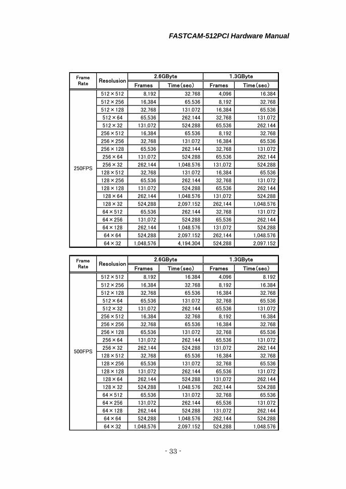
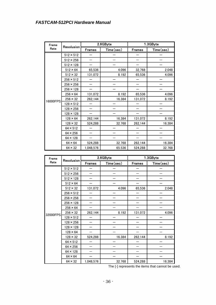
2.1.7. Frame Rate vs. Number of Recorded Frames
and Record Duration
Frames Time(sec) Frames Time(sec)
512×512 8,192 136.533 4,096 68.267
512×256 16,384 273.067 8,192 136.533
512×128 32,768 546.133 16,384 273.067
512×64 65,536 1,092.267 32,768 546.133
512×32 131,072 2,184.533 65,536 1,092.267
256×512 16,384 273.067 8,192 136.533
256×256 32,768 546.133 16,384 273.067
256×128 65,536 1,092.267 32,768 546.133
256×64 131,072 2,184.533 65,536 1,092.267
256×32 262,144 4,369.067 131,072 2,184.533
128×512 32,768 546.133 16,384 273.067
128×256 65,536 1,092.267 32,768 546.133
128×128 131,072 2,184.533 65,536 1,092.267
128×64 262,144 4,369.067 131,072 2,184.533
128×32 524,288 8,738.133 262,144 4,369.067
64×512 65,536 1,092.267 32,768 546.133
64×256 131,072 2,184.533 65,536 1,092.267
64×128 262,144 4,369.067 131,072 2,184.533
64×64 524,288 8,738.133 262,144 4,369.067
64×32 1,048,576 17,476.267 524,288 8,738.133
Frames Time(sec) Frames Time(sec)
512×512 8,192 65.536 4,096 32.768
512×256 16,384 131.072 8,192 65.536
512×128 32,768 262.144 16,384 131.072
512×64 65,536 524.288 32,768 262.144
512×32 131,072 1,048.576 65,536 524.288
256×512 16,384 131.072 8,192 65.536
256×256 32,768 262.144 16,384 131.072
256×128 65,536 524.288 32,768 262.144
256×64 131,072 1,048.576 65,536 524.288
256×32 262,144 2,097.152 131,072 1,048.576
128×512 32,768 262.144 16,384 131.072
128×256 65,536 524.288 32,768 262.144
128×128 131,072 1,048.576 65,536 524.288
128×64 262,144 2,097.152 131,072 1,048.576
128×32 524,288 4,194.304 262,144 2,097.152
64×512 65,536 524.288 32,768 262.144
64×256 131,072 1,048.576 65,536 524.288
64×128 262,144 2,097.152 131,072 1,048.576
64×64 524,288 4,194.304 262,144 2,097.152
64×32 1,048,576 8,388.608 524,288 4,194.304
FrameRate
Resolusion2.6GByte 1.3GByte
60FPS
FrameRate
Resolusion2.6GByte 1.3GByte
125FPS
FASTCAM-512PCI Hardware Manual
- 33 -
Frames Time(sec) Frames Time(sec)
512×512 8,192 32.768 4,096 16.384
512×256 16,384 65.536 8,192 32.768
512×128 32,768 131.072 16,384 65.536
512×64 65,536 262.144 32,768 131.072
512×32 131,072 524.288 65,536 262.144
256×512 16,384 65.536 8,192 32.768
256×256 32,768 131.072 16,384 65.536
256×128 65,536 262.144 32,768 131.072
256×64 131,072 524.288 65,536 262.144
256×32 262,144 1,048.576 131,072 524.288
128×512 32,768 131.072 16,384 65.536
128×256 65,536 262.144 32,768 131.072
128×128 131,072 524.288 65,536 262.144
128×64 262,144 1,048.576 131,072 524.288
128×32 524,288 2,097.152 262,144 1,048.576
64×512 65,536 262.144 32,768 131.072
64×256 131,072 524.288 65,536 262.144
64×128 262,144 1,048.576 131,072 524.288
64×64 524,288 2,097.152 262,144 1,048.576
64×32 1,048,576 4,194.304 524,288 2,097.152
Frames Time(sec) Frames Time(sec)
512×512 8,192 16.384 4,096 8.192
512×256 16,384 32.768 8,192 16.384
512×128 32,768 65.536 16,384 32.768
512×64 65,536 131.072 32,768 65.536
512×32 131,072 262.144 65,536 131.072
256×512 16,384 32.768 8,192 16.384
256×256 32,768 65.536 16,384 32.768
256×128 65,536 131.072 32,768 65.536
256×64 131,072 262.144 65,536 131.072
256×32 262,144 524.288 131,072 262.144
128×512 32,768 65.536 16,384 32.768
128×256 65,536 131.072 32,768 65.536
128×128 131,072 262.144 65,536 131.072
128×64 262,144 524.288 131,072 262.144
128×32 524,288 1,048.576 262,144 524.288
64×512 65,536 131.072 32,768 65.536
64×256 131,072 262.144 65,536 131.072
64×128 262,144 524.288 131,072 262.144
64×64 524,288 1,048.576 262,144 524.288
64×32 1,048,576 2,097.152 524,288 1,048.576
FrameRate
Resolusion2.6GByte 1.3GByte
250FPS
FrameRate
Resolusion2.6GByte 1.3GByte
500FPS

FASTCAM-512PCI Hardware Manual
- 34 -
Frames Time(sec) Frames Time(sec)
512×512 8,192 8.192 4,096 4.096
512×256 16,384 16.384 8,192 8.192
512×128 32,768 32.768 16,384 16.384
512×64 65,536 65.536 32,768 32.768
512×32 131,072 131.072 65,536 65.536
256×512 16,384 16.384 8,192 8.192
256×256 32,768 32.768 16,384 16.384
256×128 65,536 65.536 32,768 32.768
256×64 131,072 131.072 65,536 65.536
256×32 262,144 262.144 131,072 131.072
128×512 32,768 32.768 16,384 16.384
128×256 65,536 65.536 32,768 32.768
128×128 131,072 131.072 65,536 65.536
128×64 262,144 262.144 131,072 131.072
128×32 524,288 524.288 262,144 262.144
64×512 65,536 65.536 32,768 32.768
64×256 131,072 131.072 65,536 65.536
64×128 262,144 262.144 131,072 131.072
64×64 524,288 524.288 262,144 262.144
64×32 1,048,576 1,048.576 524,288 524.288
Frames Time(sec) Frames Time(sec)
512×512 8,192 4.096 4,096 2.048
512×256 16,384 8.192 8,192 4.096
512×128 32,768 16.384 16,384 8.192
512×64 65,536 32.768 32,768 16.384
512×32 131,072 65.536 65,536 32.768
256×512 16,384 8.192 8,192 4.096
256×256 32,768 16.384 16,384 8.192
256×128 65,536 32.768 32,768 16.384
256×64 131,072 65.536 65,536 32.768
256×32 262,144 131.072 131,072 65.536
128×512 32,768 16.384 16,384 8.192
128×256 65,536 32.768 32,768 16.384
128×128 131,072 65.536 65,536 32.768
128×64 262,144 131.072 131,072 65.536
128×32 524,288 262.144 262,144 131.072
64×512 65,536 32.768 32,768 16.384
64×256 131,072 65.536 65,536 32.768
64×128 262,144 131.072 131,072 65.536
64×64 524,288 262.144 262,144 131.072
64×32 1,048,576 524.288 524,288 262.144
FrameRate
Resolusion2.6GByte 1.3GByte
1000FPS
FrameRate
Resolusion2.6GByte 1.3GByte
2000FPS

FASTCAM-512PCI Hardware Manual
- 35 -
The [-] represents the items that cannot be used.
Frames Time(sec) Frames Time(sec)
512×512 - - - -
512×256 16,384 4.096 8,192 2.048
512×128 32,768 8.192 16,384 4.096
512×64 65,536 16.384 32,768 8.192
512×32 131,072 32.768 65,536 16.384
256×512 - - - -
256×256 32,768 8.192 16,384 4.096
256×128 65,536 16.384 32,768 8.192
256×64 131,072 32.768 65,536 16.384
256×32 262,144 65.536 131,072 32.768
128×512 - - - -
128×256 65,536 16.384 32,768 8.192
128×128 131,072 32.768 65,536 16.384
128×64 262,144 65.536 131,072 32.768
128×32 524,288 131.072 262,144 65.536
64×512 - - - -
64×256 131,072 32.768 65,536 16.384
64×128 262,144 65.536 131,072 32.768
64×64 524,288 131.072 262,144 65.536
64×32 1,048,576 262.144 524,288 131.072
Frames Time(sec) Frames Time(sec)
512×512 - - - -
512×256 - - - -
512×128 32,768 4.096 16,384 2.048
512×64 65,536 8.192 32,768 4.096
512×32 131,072 16.384 65,536 8.192
256×512 - - - -
256×256 - - - -
256×128 65,536 8.192 32,768 4.096
256×64 131,072 16.384 65,536 8.192
256×32 262,144 32.768 131,072 16.384
128×512 - - - -
128×256 - - - -
128×128 131,072 16.384 65,536 8.192
128×64 262,144 32.768 131,072 16.384
128×32 524,288 65.536 262,144 32.768
64×512 - - - -
64×256 - - - -
64×128 262,144 32.768 131,072 16.384
64×64 524,288 65.536 262,144 32.768
64×32 1,048,576 131.072 524,288 65.536
FrameRate
Resolusion2.6GByte 1.3GByte
4000FPS
FrameRate
Resolusion2.6GByte 1.3GByte
8000FPS
FASTCAM-512PCI Hardware Manual
- 36 -
The [-] represents the items that cannot be used.
Frames Time(sec) Frames Time(sec)
512×512 - - - -
512×256 - - - -
512×128 - - - -
512×64 65,536 4.096 32,768 2.048
512×32 131,072 8.192 65,536 4.096
256×512 - - - -
256×256 - - - -
256×128 - - - -
256×64 131,072 8.192 65,536 4.096
256×32 262,144 16.384 131,072 8.192
128×512 - - - -
128×256 - - - -
128×128 - - - -
128×64 262,144 16.384 131,072 8.192
128×32 524,288 32.768 262,144 16.384
64×512 - - - -
64×256 - - - -
64×128 - - - -
64×64 524,288 32.768 262,144 16.384
64×32 1,048,576 65.536 524,288 32.768
Frames Time(sec) Frames Time(sec)
512×512 - - - -
512×256 - - - -
512×128 - - - -
512×64 - - - -
512×32 131,072 4.096 65,536 2.048
256×512 - - - -
256×256 - - - -
256×128 - - - -
256×64 - - - -
256×32 262,144 8.192 131,072 4.096
128×512 - - - -
128×256 - - - -
128×128 - - - -
128×64 - - - -
128×32 524,288 16.384 262,144 8.192
64×512 - - - -
64×256 - - - -
64×128 - - - -
64×64 - - - -
64×32 1,048,576 32.768 524,288 16.384
FrameRate
Resolusion2.6GByte 1.3GByte
1.3GByte
32000FPS
16000FPS
FrameRate
Resolusion2.6GByte

FASTCAM-512PCI Hardware Manual
- 37 -
2.2. Dimensions
2.2.1. Camera Head (Millimeters)
SERIAL NO.
MODEL
64.28.2 5685
85
FASTCAM-512PCI Hardware Manual
- 38 -
312
98.5
22
958770
106.5
Slide to adjust( up to 12mm)
Board Guide
⇔
346.82
335.02 12
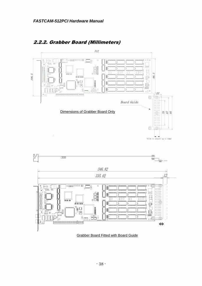
2.2.2. Grabber Board (Millimeters)
Dimensions of Grabber Board Only
Grabber Board Fitted with Board Guide
FASTCAM-512PCI Hardware Manual
- 39 -
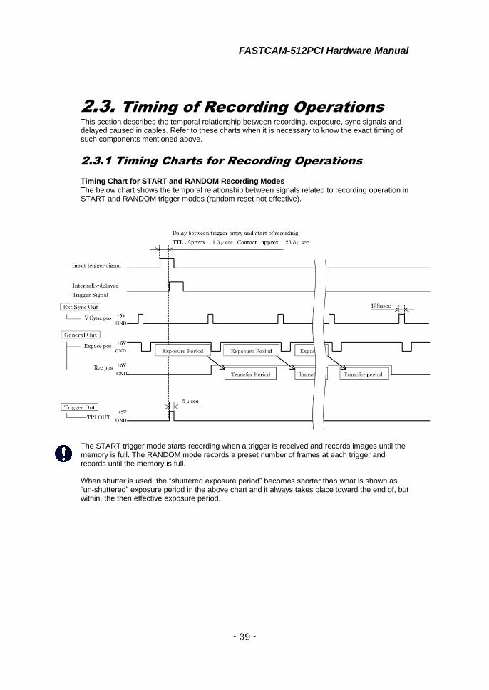
2.3. Timing of Recording Operations This section describes the temporal relationship between recording, exposure, sync signals and delayed caused in cables. Refer to these charts when it is necessary to know the exact timing of such components mentioned above.
2.3.1 Timing Charts for Recording Operations Timing Chart for START and RANDOM Recording Modes The below chart shows the temporal relationship between signals related to recording operation in START and RANDOM trigger modes (random reset not effective).
The START trigger mode starts recording when a trigger is received and records images until the memory is full. The RANDOM mode records a preset number of frames at each trigger and records until the memory is full. When shutter is used, the “shuttered exposure period” becomes shorter than what is shown as “un-shuttered” exposure period in the above chart and it always takes place toward the end of, but within, the then effective exposure period.

FASTCAM-512PCI Hardware Manual
- 40 -
Timing Chart for START and RANDOM Trigger Modes with “Reset” in Effect When “Reset” function is activated, Expose pos (vertical sync) signal is reset by the incoming trigger so that the timing of the incoming trigger signal and the start of exposure coincide more accurately as shown in the below chart.
The START trigger mode starts recording when a trigger is received and continues recording images until the memory is full. The RANDOM mode records a preset number of frames at each trigger and records until the memory is full.
FASTCAM-512PCI Hardware Manual
- 41 -
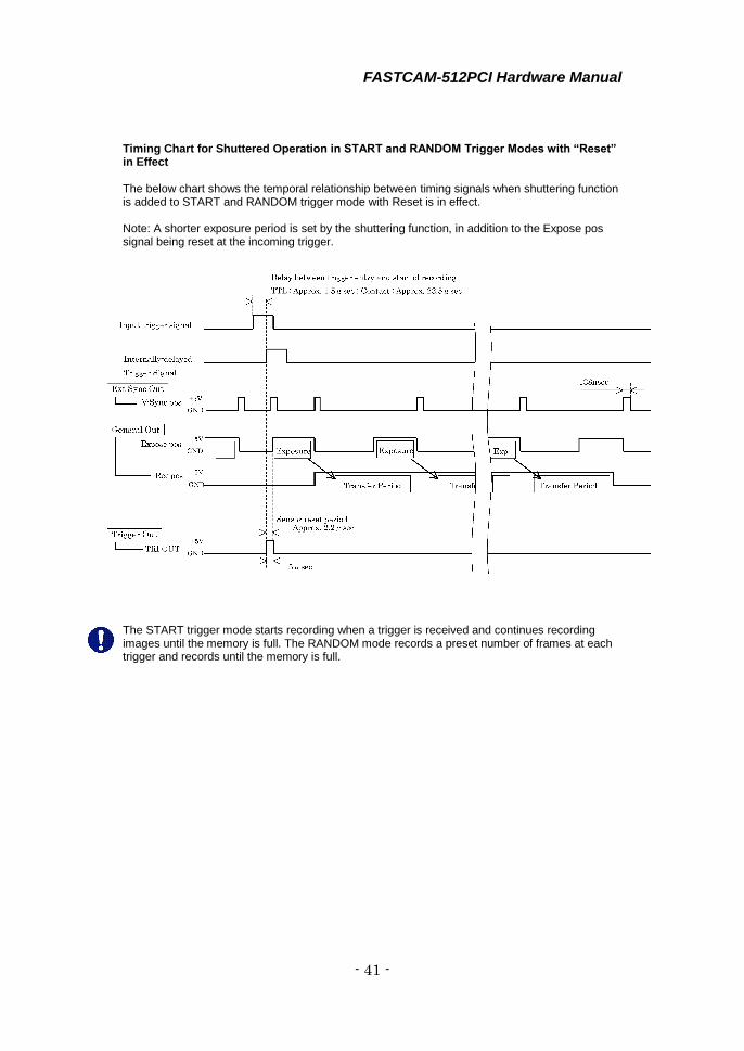
Timing Chart for Shuttered Operation in START and RANDOM Trigger Modes with “Reset” in Effect The below chart shows the temporal relationship between timing signals when shuttering function is added to START and RANDOM trigger mode with Reset is in effect. Note: A shorter exposure period is set by the shuttering function, in addition to the Expose pos signal being reset at the incoming trigger.
The START trigger mode starts recording when a trigger is received and continues recording images until the memory is full. The RANDOM mode records a preset number of frames at each trigger and records until the memory is full.
FASTCAM-512PCI Hardware Manual
- 42 -
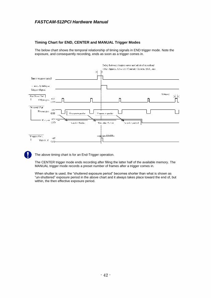
Timing Chart for END, CENTER and MANUAL Trigger Modes The below chart shows the temporal relationship of timing signals in END trigger mode. Note the exposure, and consequently recording, ends as soon as a trigger comes in.
The above timing chart is for an End-Trigger operation. The CENTER trigger mode ends recording after filling the latter half of the available memory. The MANUAL trigger mode records a preset number of frames after a trigger comes in. When shutter is used, the “shuttered exposure period” becomes shorter than what is shown as “un-shuttered” exposure period in the above chart and it always takes place toward the end of, but within, the then effective exposure period.

FASTCAM-512PCI Hardware Manual
- 43 -
2.3.2. Sync Timing in Multi-Camera Operations In multiple-camera operation of FASTCAM-512PCI cameras, if sync and trigger signals are connected in series as shown below, signal delay inevitably becomes obvious. In extreme cases, this delay may cause an offset of one full image frame between cameras involved in multiple-camera operation. To avoid this drawback, other connection methods shown in 2.4.2. are recommended.
Delay time in camera.
2.3.3. Delay of Vertical Sync and Trigger Signals in
Multiple-Camera Operation In multiple-camera operation, a signal delay is caused in V sync and trigger signals between boards.
Master Board
Internal Vsync
Approx±23nsec
Master Board
Slave Board TRI OUT
SYNC OUT
T - TTL IN
SYNC IN
TRI OUT
SYNC OUT
Slave Board SYNC IN
Slave Board SYNC OUT
5~8nsec
Slave Board
Internal Vsync

FASTCAM-512PCI Hardware Manual
- 44 -
Delay of V Sync Signal (In slave boards, the Vsync signal is a “through-out” output.) Delay of TTL Trigger Signal These delays may cause an offset of one frame between cameras in multiple-camera operation depending on a certain timing of trigger entry.
2.3.4 Recording Interval in Random Center and
Random Manual Trigger Modes In Random Center and Random Manual modes, because Center or Manual operation is repeatedly executed, the following interval is necessary between one recording and next. The interval can be checked by observing Rec Pos/Neg signal on GENERAL OUT.
Note: The necessary interval depends on the PC being used. More interval may be needed
depending on the nature of the PC. The above interval is needed when using a PC with Pentium 4 (2.4GHz).
170~260msec
Preset number of frames to record
Slave Board
SYNC IN
Slave Board
SYNC OUT
5~8nsec
Approx
1.7μsec
Slave Board
T-TTL IN
Slave Board
TRI OUT
Preset number of frames to record
FASTCAM-512PCI Hardware Manual
- 45 -
Chapter 3 Contacting Photron
3.1. Contact Information

FASTCAM-512PCI Hardware Manual
- 46 -
3.1 Contact Information For inquires related to PFV, contact Photron at the contact information listed below.
Additionally, the following items will be verified when inquiring, so please prepare them
in advance.
Items Verified Concrete Example
Contact Information
Company, school or organization name,
customer contact name,
contact phone number,
contact e-mail.
Product Name FASTCAM-512PCI
Serial Number Check on the nameplate seal.
Condition of the system and what is known about it.
Contact Information
In Americas
and Antipodes
PHOTRON USA, INC.
9520 Padgett Street, Suite 110
San Diego, CA 92126-4446, USA
Phone : 800-585-2129 or 858-684-3555
Fax : 858-684-3558
E-mail : [email protected]
www.photron.com
In Europe,
Africa and India
PHOTRON EUROPE LIMITED
The Barn, Bottom Road,
West Wycombe, Buckinghamshire,
HP14 4BS, U.K.
Phone : +44(0) 1494 48 1011
Fax : +44(0) 1494 48 7011
E-mail : [email protected]
www.photron.com
In other areas
PHOTRON LIMITED
21F, Jimbocho Mitsui Bldg.,
1-105 Kanda Jimbocho, Chiyoda-Ku, Tokyo 101-0051
Phone : +81 3 3518 6271
Fax : +81 3 3518 6279
E-mail : [email protected]
www.photron.co.jp

©2010.PHOTRON LIMITED, Al l r ights reserved. Prin ted in Japan.
(Control No. E180406U)
FFAASSTTCCAAMM--551122PPCCII
Hardware Manual Revision 1.06E (US/EU)
Publication Date April, 2018
Publisher PHOTRON LIMITED
21F, Jimbocho Mitsui Bldg.,
1-105 Kanda Jimbocho, Chiyoda-Ku, Tokyo 101-0051