Embed Size (px)
Citation preview
53-1003628-0330 October 2015
FastIron Ethernet SwitchPlatform and Layer 2SwitchingConfiguration Guide
Supporting FastIron Software Release 08.0.30d

© 2015, Brocade Communications Systems, Inc. All Rights Reserved.
ADX, Brocade, Brocade Assurance, the B-wing symbol, DCX, Fabric OS, HyperEdge, ICX, MLX, MyBrocade, OpenScript, The EffortlessNetwork, VCS, VDX, Vplane, and Vyatta are registered trademarks, and Fabric Vision and vADX are trademarks of BrocadeCommunications Systems, Inc., in the United States and/or in other countries. Other brands, products, or service names mentioned may betrademarks of others.
Notice: This document is for informational purposes only and does not set forth any warranty, expressed or implied, concerning anyequipment, equipment feature, or service offered or to be offered by Brocade. Brocade reserves the right to make changes to this documentat any time, without notice, and assumes no responsibility for its use. This informational document describes features that may not becurrently available. Contact a Brocade sales office for information on feature and product availability. Export of technical data contained inthis document may require an export license from the United States government.
The authors and Brocade Communications Systems, Inc. assume no liability or responsibility to any person or entity with respect to theaccuracy of this document or any loss, cost, liability, or damages arising from the information contained herein or the computer programs thataccompany it.
The product described by this document may contain open source software covered by the GNU General Public License or other opensource license agreements. To find out which open source software is included in Brocade products, view the licensing terms applicable tothe open source software, and obtain a copy of the programming source code, please visit http://www.brocade.com/support/oscd.
Contents
Preface...................................................................................................................................11Document conventions....................................................................................11
Text formatting conventions................................................................ 11Command syntax conventions............................................................ 11Notes, cautions, and warnings............................................................ 12
Brocade resources.......................................................................................... 13Contacting Brocade Technical Support...........................................................13Document feedback........................................................................................ 14
About This Document.............................................................................................................. 15What’s new in this document.......................................................................... 15Supported Hardware....................................................................................... 15How command information is presented in this guide.....................................16
Basic Layer 2 Features ........................................................................................................... 17About port regions...........................................................................................17
FastIron X Series device port regions................................................. 17FCX device port regions......................................................................18ICX 6610 device port regions..............................................................18ICX 6430 device port regions..............................................................18ICX 6450 device port regions..............................................................18ICX 6650 device port regions..............................................................19ICX 7450 device port regions..............................................................19ICX 7750 device port regions..............................................................19ICX 7250 device port regions..............................................................19
Enabling or disabling the Spanning Tree Protocol (STP)................................19Modifying STP bridge and port parameters........................................ 19
Management MAC address for stackable devices..........................................20MAC learning rate control............................................................................... 20Changing the MAC age time and disabling MAC address learning................ 20
Disabling the automatic learning of MAC addresses.......................... 21Displaying the MAC address table...................................................... 21
Static MAC entry configuration........................................................................22Multi-port static MAC address............................................................. 22
VLAN-based static MAC entries configuration................................................ 23Configuring a VLAN to drop static MAC entries.................................. 24
Clearing MAC address entries........................................................................ 24Flow-based MAC address learning................................................................. 24
Flow-based learning overview.............................................................24Flow-based learning configuration considerations.............................. 26Configuring flow-based MAC address learning...................................26Displaying information about flow-based MACs..................................27Clearing flow-based MAC address entries..........................................28
Enabling port-based VLANs............................................................................28Assigning IEEE 802.1Q tagging to a port............................................29
Defining MAC address filters...........................................................................29Monitoring MAC address movement...............................................................30
Configuring the MAC address movement threshold rate.................... 30
FastIron Ethernet Switch Platform and Layer 2 Switching Configuration Guide 353-1003628-03
Viewing the MAC address movement threshold rateconfiguration................................................................................31
Configuring an interval for collecting MAC address movenotifications..................................................................................32
Viewing MAC address movement statistics for the interval history...32SNMP MAC-notification trap support............................................................ 33
Requirements and limitations for MAC-notification trap support.......34Configuring SNMP traps for MAC-notification ..................................34MAC-notification events.................................................................... 35
Displaying and modifying system parameter default settings....................... 36System default settings configuration considerations....................... 37Displaying system parameter default values.....................................37Modifying system parameter default values......................................42
Cut-through switching................................................................................... 43Dynamic buffer allocation for QoS priorities for FastIron X Series
devices.................................................................................................... 44Default queue depth limits for FastIron X Series devices................. 44Configuring the total transmit queue depth limit for FastIron X
Series devices............................................................................. 45Configuring the transmit queue depth limit for a given traffic
class on FastIron X Series devices............................................. 45Removing buffer allocation limits on FastIron X Series devices....... 46Buffer profile configuration................................................................ 46Default queue depth limits for FastIron X Series devices................. 48
Dynamic buffer allocation for FCX and ICX devices..................................... 48Configuring buffer profiles.................................................................48Configuring buffer sharing on FCX and ICX devices........................ 57Removing buffer allocation limits on FCX and ICX........................... 60Buffer profiles for VoIP on FastIron stackable devices..................... 61
Buffer allocation for ICX 6650....................................................................... 61Buffer and descriptor maximum and default allocation values for
ICX 6650......................................................................................62ICX 6650 buffer sharing levels..........................................................62Displaying buffer sharing information on the ICX 6650.....................63
Ethernet loopback......................................................................................... 63Ethernet loopback operational modes.............................................. 63Ethernet loopback configuration considerations............................... 64Configuring Ethernet loopback in VLAN-unaware mode.................. 65Configuring Ethernet loopback in VLAN-aware mode...................... 66Ethernet loopback syslog messages.................................................67
Remote Fault Notification on 1Gbps fiber connections.................................67Enabling and disabling remote fault notification................................67
Link Fault Signaling for 10Gbps Ethernet devices........................................ 68Enabling Link Fault Signaling............................................................68Viewing the status of LFS-enabled links........................................... 68
Jumbo frame support.................................................................................... 69Packet InError Detection...............................................................................69
Configuring Packet InError Detection................................................70Syslog message for error-disabled port due to inError packets........70
Metro Features..................................................................................................................... 71Topology groups........................................................................................... 71
Master VLAN and member VLANs................................................... 71Control ports and free ports.............................................................. 72Topology group configuration considerations................................... 72Configuring a topology group............................................................72Displaying topology group information..............................................73
4 FastIron Ethernet Switch Platform and Layer 2 Switching Configuration Guide53-1003628-03
Metro Ring Protocol ....................................................................................... 74Metro Ring Protocol configuration notes............................................. 76MRP rings without shared interfaces (MRP Phase 1).........................76MRP rings with shared interfaces (MRP Phase 2)..............................77Ring initialization................................................................................. 79How ring breaks are detected and healed.......................................... 83Master VLANs and customer VLANs.................................................. 85Metro Ring Protocol configuration.......................................................87Metro Ring Protocol diagnostics......................................................... 89Displaying MRP information................................................................90MRP CLI example............................................................................... 93
VSRP.............................................................................................................. 95VSRP configuration notes and feature limitations...............................97Layer 2 and Layer 3 redundancy........................................................ 97Master election and failover................................................................ 97VSRP-aware security features.......................................................... 102VSRP parameters............................................................................. 102Configuring basic VSRP parameters................................................ 106Configuring optional VSRP parameters............................................ 106Displaying VSRP information............................................................ 115VSRP fast start..................................................................................118VSRP and MRP signaling................................................................. 119
UDLD and Protected Link Groups...........................................................................................123UDLD overview............................................................................................. 123
UDLD for tagged ports...................................................................... 123Configuration notes and feature limitations for UDLD.......................124Enabling UDLD................................................................................. 124Enabling UDLD for tagged ports....................................................... 125Changing the Keepalive interval....................................................... 125Changing the Keepalive retries......................................................... 125Displaying UDLD information............................................................ 125Clearing UDLD statistics................................................................... 128
Protected link groups.................................................................................... 128About active ports............................................................................. 128Using UDLD with protected link groups............................................ 128UDLD with protected link groups configuration notes....................... 129Creating a protected link group and assigning an active port........... 130
Link Aggregation...................................................................................................................133Overview of link aggregation.........................................................................133LAG formation rules...................................................................................... 134Configuration notes for FastIron devices in a traditional stack......................135Maximum number of LAGs........................................................................... 137Migrating from a previous release to 08.0.00a LAG or LACP configuration. 138Downgrade considerations............................................................................139LAG Load Sharing.........................................................................................140LAG hashing on stacking products .............................................................. 141
Removing Layer 2 information from LAG hash output...................... 141Symmetric load balancing................................................................. 141
Configuring a LAG.........................................................................................144Creating a Link Aggregation Group (LAG)........................................ 144Creating a Link Aggregation Group (LAG) using the LAG ID option.144
Deploying a LAG........................................................................................... 149Commands available under LAG once it is deployed....................... 149Disabling ports within a LAG............................................................. 150
FastIron Ethernet Switch Platform and Layer 2 Switching Configuration Guide 553-1003628-03
Enabling ports within a LAG............................................................150Adding a Port to Currently Deployed LAG...................................... 150Deleting a Port from a Currently Deployed LAG............................. 151Monitoring an individual LAG port...................................................151Assigning a name to a port within a LAG........................................152Enabling sFlow forwarding on a port in a LAG................................153Setting the sFlow sampling rate for a port in a LAG....................... 153IP assignment within a LAG............................................................154Renaming an existing LAG............................................................. 154Displaying LAG information.............................................................154Displaying information about LAG interface....................................159Enabling LAG hardware failover .................................................... 160
Preboot eXecution Environment boot support............................................ 160Enabling PXE boot support on a port..............................................161
User-configured peer information per LACP...............................................161
Multi-Chassis Trunking....................................................................................................... 163Multi-Chassis Trunking Overview................................................................163
How MCT works..............................................................................163MCT terminology.............................................................................164MCT data flow.................................................................................165MCT and VLANs............................................................................. 168Cluster client automatic configuration............................................. 168MCT feature interaction...................................................................169Basic MCT configuration.................................................................170Setting up cluster client automatic configuration ............................174MCT failover scenarios................................................................... 176
Layer 2 behavior with MCT......................................................................... 179MAC operations.............................................................................. 179Port loop detection.......................................................................... 182MCT Layer 2 protocols....................................................................183Protocol-based VLANs....................................................................184Uplink switch................................................................................... 184Layer 2 multicast snooping over MCT.............................................184Forcing a port up in a basic MCT configuration.............................. 187
Displaying MCT information........................................................................188Displaying peer and client states.................................................... 188Displaying state machine information............................................. 189Displaying cluster, peer, and client states.......................................190Displaying information about Ethernet interfaces........................... 190Displaying STP information.............................................................191Displaying information for multicast snooping.................................191
MCT configuration examples ..................................................................... 193Single-level MCT example.............................................................. 193Two-level MCT example................................................................. 196Multicast snooping configuration example...................................... 201MCT configuration examples using STP ........................................204
GVRP..................................................................................................................................211GVRP overview...........................................................................................211GVRP application examples....................................................................... 211
Dynamic core and fixed edge..........................................................212Dynamic core and dynamic edge....................................................213Fixed core and dynamic edge.........................................................213Fixed core and fixed edge...............................................................213
VLAN names created by GVRP..................................................................214
6 FastIron Ethernet Switch Platform and Layer 2 Switching Configuration Guide53-1003628-03
Configuration notes for GVRP.......................................................................214GVRP configuration...................................................................................... 215
Changing the GVRP base VLAN ID..................................................215Increasing the maximum configurable value of the Leaveall timer... 216Enabling GVRP................................................................................. 216Disabling VLAN advertising...............................................................217Disabling VLAN learning................................................................... 217Changing the GVRP timers...............................................................217
Converting a VLAN created by GVRP into a statically-configured VLAN..... 219Displaying GVRP information........................................................................220
Displaying GVRP configuration information...................................... 220Displaying GVRP VLAN information................................................. 223Displaying GVRP statistics................................................................225
Clearing GVRP statistics...............................................................................226GVRP CLI examples..................................................................................... 227
Dynamic core and fixed edge............................................................227Dynamic core and dynamic edge......................................................228Fixed core and dynamic edge........................................................... 228Fixed core and fixed edge.................................................................229
Port mirroring and Monitoring............................................................................................... 231Port mirroring and monitoring overview........................................................ 231Port mirroring and monitoring configuration.................................................. 231
Configuration notes for port mirroring and monitoring.......................232Command syntax for port mirroring and monitoring..........................233
Mirroring configuration on a traditional stack................................................ 234Configuration notes for traditional stack mirroring.............................234
ACL-based inbound mirroring....................................................................... 235Creating an ACL-based inbound mirror clause for FCX and ICX
devices........................................................................................ 235ACL-based inbound mirror clauses for FastIron X Series devices....236Destination mirror port ......................................................................236
MAC address filter-based mirroring.............................................................. 239Configuring MAC address filter-based mirroring............................... 239
VLAN-based mirroring...................................................................................240Configuring VLAN-based mirroring................................................... 241Displaying VLAN-based mirroring status.......................................... 241Configuration notes for VLAN-based mirroring................................. 241VLAN-based mirroring.......................................................................242
Spanning Tree Protocol......................................................................................................... 247STP overview................................................................................................ 247Standard STP parameter configuration.........................................................247
STP parameters and defaults........................................................... 248Enabling or disabling the Spanning Tree Protocol (STP)..................249Changing STP bridge and port parameters...................................... 251STP protection enhancement............................................................252Displaying STP information...............................................................254
STP feature configuration............................................................................. 261Fast port span................................................................................... 261Fast Uplink Span...............................................................................263802.1W Rapid Spanning Tree (RSTP)..............................................266802.1W Draft 3.................................................................................. 302Single Spanning Tree (SSTP)...........................................................306STP per VLAN group........................................................................ 308
PVST/PVST+ compatibility............................................................................312
FastIron Ethernet Switch Platform and Layer 2 Switching Configuration Guide 753-1003628-03
Overview of PVST and PVST+....................................................... 313VLAN tags and dual mode.............................................................. 313Configuring PVST+ support............................................................ 314Displaying PVST+ support information........................................... 315PVST+ configuration examples.......................................................315
PVRST compatibility................................................................................... 318BPDU guard................................................................................................318
Enabling BPDU protection by port.................................................. 318Re-enabling ports disabled by BPDU guard................................... 319Displaying the BPDU guard status..................................................319BPDU guard status example console messages ...........................320
Root guard.................................................................................................. 321Enabling STP root guard.................................................................321Displaying the STP root guard........................................................ 321Displaying the root guard by VLAN.................................................322
Designated Protection.................................................................................322Enabling Designated Protection on a port...................................... 323Syslog message for a port in designated inconsistent state........... 323
Error disable recovery.................................................................................323Enabling an error-disabled port automatically.................................323Enabling an error-disabled port manually....................................... 324Setting the recovery interval............................................................324Displaying the error disable recovery state by interface ................ 324Displaying the recovery state for all conditions...............................324Displaying the recovery state by port number and cause............... 325Errdisable Syslog messages...........................................................325
802.1s Multiple Spanning Tree Protocol..................................................... 325Multiple spanning-tree regions .......................................................325Configuration notes.........................................................................327Configuring MSTP mode and scope............................................... 327Reduced occurrences of MSTP reconvergence............................. 328Configuring additional MSTP parameters....................................... 330
VLANs.................................................................................................................................341VLAN overview............................................................................................341
Types of VLANs.............................................................................. 341Modifying a port-based VLAN......................................................... 347Default VLAN.................................................................................. 356802.1Q tagging................................................................................357Spanning Tree Protocol (STP)........................................................359Virtual routing interfaces................................................................. 360VLAN and virtual routing interface groups...................................... 361Dynamic, static, and excluded port membership............................ 362Super aggregated VLANs............................................................... 365Trunk group ports and VLAN membership......................................365Summary of VLAN configuration rules............................................365
Routing between VLANs.............................................................................366Virtual routing interfaces (Layer 2 Switches only)...........................366Routing between VLANs using virtual routing interfaces (Layer
3 Switches only)........................................................................ 367Dynamic port assignment (Layer 2 Switches and Layer 3
Switches)...................................................................................368Assigning a different VLAN ID to the default VLAN........................ 368Assigning different VLAN IDs to reserved VLANs 4091 and 4092. 368Assigning trunk group ports............................................................ 369Enable spanning tree on a VLAN....................................................369
Configuring IP subnet, IPX network and protocol-based VLANs................ 371
8 FastIron Ethernet Switch Platform and Layer 2 Switching Configuration Guide53-1003628-03
IP subnet, IPX network, and protocol-based VLAN configurationexample....................................................................................... 371
IP subnet, IPX network, and protocol-based VLANs within port-basedVLANs..................................................................................................... 372
Configuring Layer 3 VLANs on Device-A.......................................... 373Configuring Layer 3 VLANs on Device-B.......................................... 374Configuring Layer 3 VLANs on Device-C..........................................375
IPv6 protocol VLAN configuration................................................................. 376Routing between VLANs using virtual routing interfaces (Layer 3
Switches only)......................................................................................... 376Configuring Layer 3 VLANs and virtual routing interfaces on the
Device-A...................................................................................... 377Configuring Layer 3 VLANs and virtual routing interfaces for
Device-B...................................................................................... 379Configuring Layer 3 VLANs and virtual routing interfaces for
Device-C......................................................................................380Configuring protocol VLANs with dynamic ports........................................... 381
Aging of dynamic ports......................................................................382Configuration guidelines for membership aging of dynamic VLAN
ports.............................................................................................383Configuring an IP, IPX, or AppleTalk Protocol VLAN with
Dynamic Ports............................................................................. 383Configuring an IP subnet VLAN with dynamic ports......................... 384Configuring an IPX network VLAN with dynamic ports..................... 384
Configuring uplink ports within a port-based VLAN.......................................385Configuration considerations for uplink ports within a port-based
VLAN........................................................................................... 385Configuration syntax for uplink ports within a port-based VLAN....... 385
IP subnet address on multiple port-based VLANconfiguration......................386VLAN groups and virtual routing interface group ......................................... 389
Configuring a VLAN group................................................................ 390Configuring a virtual routing interface group..................................... 391Displaying the VLAN group and virtual routing interface group
information...................................................................................392Allocating memory for more VLANs or virtual routing interfaces.......393
Super-aggregated VLAN configuration......................................................... 394Configuration notes for aggregated VLANs...................................... 396Configuring aggregated VLANs........................................................ 397Verifying the aggregated VLAN configuration................................... 398Complete CLI examples for aggregated VLANs............................... 398
802.1ad tagging configuration.......................................................................401Configuration rules for 802.1ad tagging............................................ 402Enabling 802.1ad tagging................................................................. 403Example 802.1ad configuration.........................................................403Configuring 802.1ad tag profiles....................................................... 404
Private VLAN configuration........................................................................... 405Configuration notes for PVLANs and standard VLANs..................... 409Enabling broadcast or unknown unicast traffic to the PVLAN on
FSX devices................................................................................ 412CLI example for a general PVLAN network...................................... 413CLI example for a PVLAN network with switch-switch link ports...... 413Multiple promiscuous ports support in private VLANs ......................414
Dual-mode VLAN ports................................................................................. 415Displaying VLAN information........................................................................ 417
Displaying VLANs in alphanumeric order..........................................418Displaying system-wide VLAN information....................................... 418Displaying global VLAN information..................................................419Displaying VLAN information for specific ports................................. 419
FastIron Ethernet Switch Platform and Layer 2 Switching Configuration Guide 953-1003628-03

Displaying a port VLAN membership.............................................. 419Displaying a port dual-mode VLAN membership............................ 420Displaying port default VLAN IDs (PVIDs)...................................... 420Displaying PVLAN information........................................................421
10 FastIron Ethernet Switch Platform and Layer 2 Switching Configuration Guide53-1003628-03
Preface
● Document conventions....................................................................................................11● Brocade resources.......................................................................................................... 13● Contacting Brocade Technical Support...........................................................................13● Document feedback........................................................................................................ 14
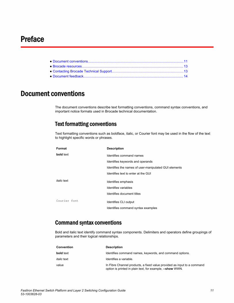
Document conventionsThe document conventions describe text formatting conventions, command syntax conventions, andimportant notice formats used in Brocade technical documentation.
Text formatting conventionsText formatting conventions such as boldface, italic, or Courier font may be used in the flow of the textto highlight specific words or phrases.
Format Description
bold text Identifies command names
Identifies keywords and operands
Identifies the names of user-manipulated GUI elements
Identifies text to enter at the GUI
italic text Identifies emphasis
Identifies variables
Identifies document titles
Courier font Identifies CLI output
Identifies command syntax examples
Command syntax conventionsBold and italic text identify command syntax components. Delimiters and operators define groupings ofparameters and their logical relationships.
Convention Description
bold text Identifies command names, keywords, and command options.
italic text Identifies a variable.
value In Fibre Channel products, a fixed value provided as input to a commandoption is printed in plain text, for example, --show WWN.
FastIron Ethernet Switch Platform and Layer 2 Switching Configuration Guide 1153-1003628-03
Convention Description
[ ] Syntax components displayed within square brackets are optional.
Default responses to system prompts are enclosed in square brackets.
{ x | y | z } A choice of required parameters is enclosed in curly brackets separated byvertical bars. You must select one of the options.
In Fibre Channel products, square brackets may be used instead for thispurpose.
x | y A vertical bar separates mutually exclusive elements.
< > Nonprinting characters, for example, passwords, are enclosed in anglebrackets.
... Repeat the previous element, for example, member[member...].
\ Indicates a “soft” line break in command examples. If a backslash separatestwo lines of a command input, enter the entire command at the prompt withoutthe backslash.
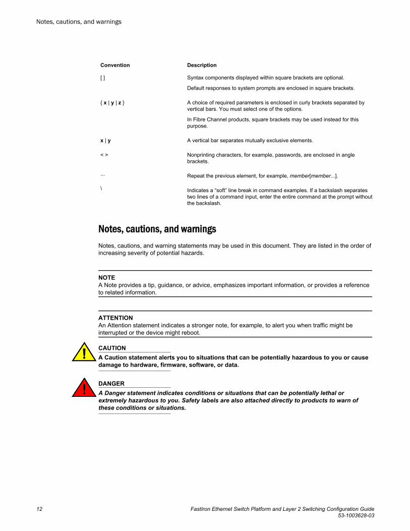
Notes, cautions, and warningsNotes, cautions, and warning statements may be used in this document. They are listed in the order ofincreasing severity of potential hazards.
NOTEA Note provides a tip, guidance, or advice, emphasizes important information, or provides a referenceto related information.
ATTENTIONAn Attention statement indicates a stronger note, for example, to alert you when traffic might beinterrupted or the device might reboot.
CAUTIONA Caution statement alerts you to situations that can be potentially hazardous to you or causedamage to hardware, firmware, software, or data.
DANGERA Danger statement indicates conditions or situations that can be potentially lethal orextremely hazardous to you. Safety labels are also attached directly to products to warn ofthese conditions or situations.
Notes, cautions, and warnings
12 FastIron Ethernet Switch Platform and Layer 2 Switching Configuration Guide53-1003628-03
Brocade resourcesVisit the Brocade website to locate related documentation for your product and additional Brocaderesources.
You can download additional publications supporting your product at www.brocade.com. Select theBrocade Products tab to locate your product, then click the Brocade product name or image to open theindividual product page. The user manuals are available in the resources module at the bottom of thepage under the Documentation category.
To get up-to-the-minute information on Brocade products and resources, go to MyBrocade. You canregister at no cost to obtain a user ID and password.
Release notes are available on MyBrocade under Product Downloads.
White papers, online demonstrations, and data sheets are available through the Brocade website.
Contacting Brocade Technical SupportAs a Brocade customer, you can contact Brocade Technical Support 24x7 online, by telephone, or by e-mail. Brocade OEM customers contact their OEM/Solutions provider.
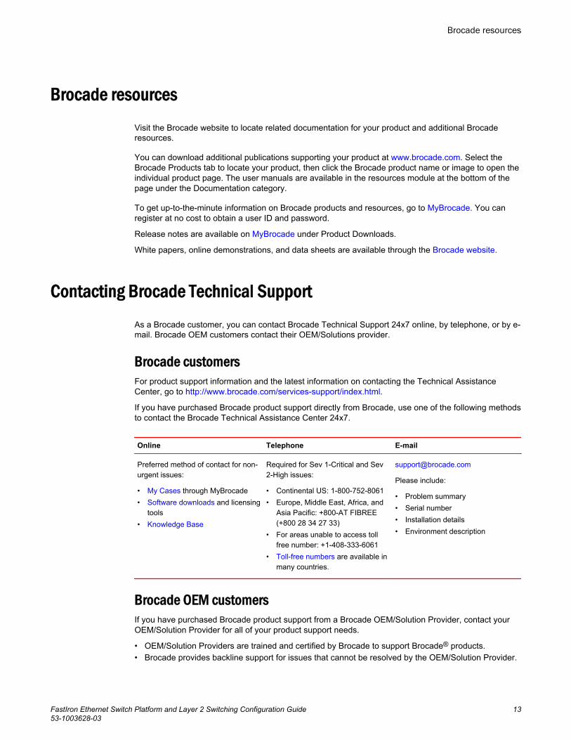
Brocade customersFor product support information and the latest information on contacting the Technical AssistanceCenter, go to http://www.brocade.com/services-support/index.html.
If you have purchased Brocade product support directly from Brocade, use one of the following methodsto contact the Brocade Technical Assistance Center 24x7.
Online Telephone E-mail
Preferred method of contact for non-urgent issues:
• My Cases through MyBrocade• Software downloads and licensing
tools• Knowledge Base
Required for Sev 1-Critical and Sev2-High issues:
• Continental US: 1-800-752-8061• Europe, Middle East, Africa, and
Asia Pacific: +800-AT FIBREE(+800 28 34 27 33)
• For areas unable to access tollfree number: +1-408-333-6061
• Toll-free numbers are available inmany countries.
Please include:
• Problem summary• Serial number• Installation details• Environment description
Brocade OEM customersIf you have purchased Brocade product support from a Brocade OEM/Solution Provider, contact yourOEM/Solution Provider for all of your product support needs.
• OEM/Solution Providers are trained and certified by Brocade to support Brocade® products.• Brocade provides backline support for issues that cannot be resolved by the OEM/Solution Provider.
Brocade resources
FastIron Ethernet Switch Platform and Layer 2 Switching Configuration Guide 1353-1003628-03
• Brocade Supplemental Support augments your existing OEM support contract, providing directaccess to Brocade expertise. For more information, contact Brocade or your OEM.
• For questions regarding service levels and response times, contact your OEM/Solution Provider.
Document feedbackTo send feedback and report errors in the documentation you can use the feedback form posted withthe document or you can e-mail the documentation team.
Quality is our first concern at Brocade and we have made every effort to ensure the accuracy andcompleteness of this document. However, if you find an error or an omission, or you think that a topicneeds further development, we want to hear from you. You can provide feedback in two ways:
• Through the online feedback form in the HTML documents posted on www.brocade.com.• By sending your feedback to [email protected].
Provide the publication title, part number, and as much detail as possible, including the topic headingand page number if applicable, as well as your suggestions for improvement.
Document feedback
14 FastIron Ethernet Switch Platform and Layer 2 Switching Configuration Guide53-1003628-03
About This Document
● What’s new in this document.......................................................................................... 15● Supported Hardware....................................................................................................... 15● How command information is presented in this guide.....................................................16
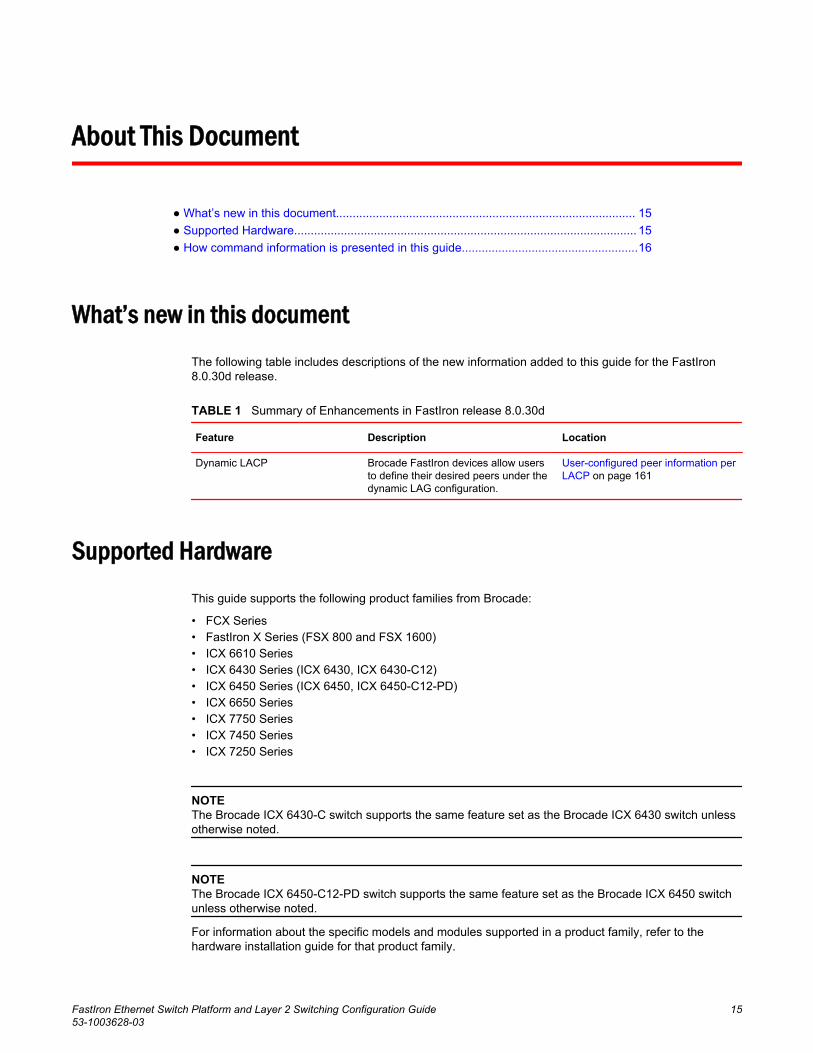
What’s new in this documentThe following table includes descriptions of the new information added to this guide for the FastIron8.0.30d release.
Summary of Enhancements in FastIron release 8.0.30dTABLE 1
Feature Description Location
Dynamic LACP Brocade FastIron devices allow usersto define their desired peers under thedynamic LAG configuration.
User-configured peer information perLACP on page 161
Supported HardwareThis guide supports the following product families from Brocade:
• FCX Series• FastIron X Series (FSX 800 and FSX 1600)• ICX 6610 Series• ICX 6430 Series (ICX 6430, ICX 6430-C12)• ICX 6450 Series (ICX 6450, ICX 6450-C12-PD)• ICX 6650 Series• ICX 7750 Series• ICX 7450 Series• ICX 7250 Series
NOTEThe Brocade ICX 6430-C switch supports the same feature set as the Brocade ICX 6430 switch unlessotherwise noted.
NOTEThe Brocade ICX 6450-C12-PD switch supports the same feature set as the Brocade ICX 6450 switchunless otherwise noted.
For information about the specific models and modules supported in a product family, refer to thehardware installation guide for that product family.
FastIron Ethernet Switch Platform and Layer 2 Switching Configuration Guide 1553-1003628-03
How command information is presented in this guideFor all new content supported in FastIron Release 08.0.20 and later, command information isdocumented in a standalone command reference guide.
In an effort to provide consistent command line interface (CLI) documentation for all products, Brocadeis in the process of completing a standalone command reference for the FastIron platforms. Thisprocess involves separating command syntax and parameter descriptions from configuration tasks.Until this process is completed, command information is presented in two ways:
• For all new content supported in FastIron Release 08.0.20 and later, the CLI is documented inseparate command pages included in the FastIron Command Reference. Command pages arecompiled in alphabetical order and follow a standard format to present syntax, parameters, usageguidelines, examples, and command history.
NOTEMany commands from previous FastIron releases are also included in the command reference.
• Legacy content in configuration guides continues to include command syntax and parameterdescriptions in the chapters where the features are documented.
If you do not find command syntax information embedded in a configuration task, refer to the FastIronCommand Reference.
How command information is presented in this guide
16 FastIron Ethernet Switch Platform and Layer 2 Switching Configuration Guide53-1003628-03
Basic Layer 2 Features
● About port regions...........................................................................................................17● Enabling or disabling the Spanning Tree Protocol (STP)................................................19● Management MAC address for stackable devices..........................................................20● MAC learning rate control............................................................................................... 20● Changing the MAC age time and disabling MAC address learning................................ 20● Static MAC entry configuration........................................................................................22● VLAN-based static MAC entries configuration................................................................ 23● Clearing MAC address entries........................................................................................ 24● Flow-based MAC address learning................................................................................. 24● Enabling port-based VLANs............................................................................................28● Defining MAC address filters...........................................................................................29● Monitoring MAC address movement...............................................................................30● SNMP MAC-notification trap support.............................................................................. 33● Displaying and modifying system parameter default settings......................................... 36● Cut-through switching..................................................................................................... 43● Dynamic buffer allocation for QoS priorities for FastIron X Series devices.....................44● Dynamic buffer allocation for FCX and ICX devices....................................................... 48● Buffer allocation for ICX 6650......................................................................................... 61● Ethernet loopback........................................................................................................... 63● Remote Fault Notification on 1Gbps fiber connections................................................... 67● Link Fault Signaling for 10Gbps Ethernet devices.......................................................... 68● Jumbo frame support...................................................................................................... 69● Packet InError Detection................................................................................................. 69
About port regionsThis section describes port regions on FastIron switches.
FastIron X Series device port regionsPorts on the FastIron X Series devices are grouped into regions. For a few features, you will need toknow the region to which a port belongs. However, for most features, a port region does not affectconfiguration or operation of the feature.
NOTEPort regions do not apply to trunk group configurations on the FastIron X Series devices. However, portregions do apply to port monitoring and unknown unicast configurations on FastIron X Series devices.
• SX-FI48GPP: ports 1 - 48 belong to port region 0• SX-FI-2XG: ports 1 - 2 belong to port region 0• SX-FI-8XG: ports 1 - 8 belong to port region 0
FastIron Ethernet Switch Platform and Layer 2 Switching Configuration Guide 1753-1003628-03
• SX-FI-24HF: ports 1 - 24 belong to port region 0• SX-FI-24GPP: ports 1 - 24 belong to port region 0
FCX device port regionsThe port region rules for FCX devices are as follows:
• For all platforms, a 24-port Gbps module has one port region. In addition, any 10 Gbps ports on thedevice also belong to this single port region.
• For all platforms, the 48-port Gbps module has two port regions:
‐ Ports 1 - 24 belong to port region 0‐ Ports 25 - 48 belong to port region 1
• For FCX648 devices with two 10 Gbps XFP ports, and a two 10 Gbps CX4 stacking ports:
‐ The two 10 Gbps XFP ports belong to port region 0 (along with ports 1 -24 )‐ The two 10 Gbps CX4 stacking ports belong to port region 1 (along with ports 25 - 48)
• For FCX648 devices with four 10 Gbps SFP+ ports:
‐ 10 Gbps SFP+ ports 3 and 4 belong to port region 0 (along with ports 1 -24 )‐ 10 Gbps SFP+ ports 1 and 2 ports belong to port region 1 (along with ports 25 - 48)
ICX 6610 device port regions• A 24-port Gbps has the following port regions:
‐ Ports 1-24 belong to region 0‐ 10 Gbps SFP+ ports belong to region 0
• A 48-port Gbps has the following port regions:
‐ Ports 1-24 belong to region 0‐ Ports 25-48 belong to region 1‐ 10 Gbps SFP+ ports belong to region 0
ICX 6430 device port regions• A 24-port Gbps module has one port region. The four SFP ports on the device also belong to this
single port region.• A 48-port Gbps module has two port regions:
‐ Ports 1-24 and SFP ports 1& 2 belong to port region 0‐ Ports 25-48 and SFP ports 3 & 4 belong to port region 1
ICX 6450 device port regions• A 24-port Gbps module has one port region. The four SFP+ ports on the device also belong to this
single port region.• A 48-port Gbps module has two port regions:
‐ Ports 1-24 and SFP+ ports 1& 2 belong to port region 0‐ Ports 25-48 and SFP+ ports 3 & 4 belong to port region 1
FCX device port regions
18 FastIron Ethernet Switch Platform and Layer 2 Switching Configuration Guide53-1003628-03
ICX 6650 device port regionsICX 6650 device has only one port region.
Brocade ICX 6650 has only one port region. All ports belong to region 0.
ICX 7450 device port regions
Brocade ICX 7450 24 port has only one port region.
Brocade ICX 7450 48 port has two port regions.
ICX 7750 device port regionsICX 7750 device has only one port region.
Brocade ICX 7750 has only one port region. All ports belong to region 0.
ICX 7250 device port regionsICX 7250 device has only one port region. All ports belong to region 0.
Enabling or disabling the Spanning Tree Protocol (STP)
STP (IEEE 802.1D bridge protocol) is supported on all Brocade devices. STP detects and eliminateslogical loops in the network. STP also ensures that the least cost path is taken when multiple paths existbetween ports or VLANs. If the selected path fails, STP searches for and then establishes an alternatepath to prevent or limit retransmission of data.
NOTEThis section provides instructions for enabling and disabling STP. For configuration procedures andmore information about STP, refer to Spanning Tree Protocol on page 247 in this guide.
STP must be enabled at the system level to allow assignment of this capability on the VLAN level. Ondevices running Layer 2 code, STP is enabled by default. On devices running Layer 3 code, STP isdisabled by default.
To enable STP for all ports on a Brocade device, enter the following command.
device(config)#spanning treeSyntax: [no] spanning-tree
You can also enable and disable spanning tree on a port-based VLAN and on an individual port basis,and enable advanced STP features. Refer to Spanning Tree Protocol on page 247.
Modifying STP bridge and port parametersYou can modify the following STP Parameters:
ICX 6650 device port regions
FastIron Ethernet Switch Platform and Layer 2 Switching Configuration Guide 1953-1003628-03
• Bridge parameters - forward delay, maximum age, hello time, and priority• Port parameters - priority and path cost
For configuration details, refer to Changing STP bridge and port parameters on page 251.
Management MAC address for stackable devicesIn a traditional stack, the management MAC address of the Active Controller is always used as theSTP bridge ID. The Active Controller management MAC address is always used for control protocolsfor the following reasons:
• Unlike standalone devices, each stack member has a different range of MAC addresses.• In a stack, the management MAC address is software generated, and is always the MAC address of
the Active Controller first port. This ensures consistency across the stack during resets, assumingthat the Active Controller is always the same unit.
• This helps avoid the disruption of frequent topology changes in the stack.
For more information about stacking and Brocade stackable devices, refer to the FastIron EthernetSwitch Stacking Configuration Guide .
MAC learning rate control
NOTEThe MAC learning rate control feature is not supported on ICX 7750, ICX 7450 and ICX 7250 devices.
You can set a rate limit to control CPU address updating. The range for this rate limit is 200 to 50,000per second. The MAC learning rate limit applies to each packet processor, which means that for asystem with two packet processors, each processor can send address messages to the CPU at theestablished rate limit.
Syntax: [no] cpu-limit addr-msgs msgsRateLimit
NOTEActual rates in hardware may have a variance of +200 or -100.
Changing the MAC age time and disabling MAC address learning
To change the MAC address age timer, enter a command such as the following.
device(config)#mac-age-time 60Syntax: [no] mac-age-time secs
secs specifies the number of seconds. Possible values differ depending on the version of softwarerunning on your device, as follows:
Management MAC address for stackable devices
20 FastIron Ethernet Switch Platform and Layer 2 Switching Configuration Guide53-1003628-03
• On Brocade FCX Series devices, you can configure the MAC address age timer to 0 or a value from10-1000 (seconds). If you set the MAC age time to 0, aging is disabled.
• On FastIron X Series devices, you can configure 0 or a value from 10 - 86,400 (seconds), in 10-second intervals. If you set the MAC age time to 0, aging is disabled.
• On ICX Series devices, you can configure the MAC address age timer to 0 or a value from 10-570(seconds). If you set the MAC age time to 0, aging is disabled.
• If the total MAC addresses in the system is more than 16000, Brocade recommends a MAC agetimer greater than 60 seconds. If the total MAC addresses in the system is more than 64000,Brocade recommends a MAC age timer greater than 120 seconds.
On ICX 6650, you can configure a value from 0 or a value from 10-600. The default is 300. If you set theMAC age time to 0, aging is disabled. On ICX 7450 and ICX 7750 you can configure a value of60-86400.
NOTEUsually, the actual MAC age time is from one to two times the configured value. For example, if you setthe MAC age timer to 60 seconds, learned MAC entries age out after remaining unused for between 60- 120 seconds. However, if all of the following conditions are met, then the MAC entries age out after alonger than expected duration:
• The MAC age timer is greater than 630 seconds.• The number of MAC entries is over 6000.• All MAC entries are learned from the same packet processor.• All MAC entries age out at the same time.
Disabling the automatic learning of MAC addressesBy default, when a packet with an unknown Source MAC address is received on a port, the Brocadedevice learns this MAC address on the port.
You can prevent a physical port from learning MAC addresses by entering the following command.
device(config)#interface ethernet 3/1/1device(config-if-e1000-3/1/1)#mac-learn-disableSyntax: [no] mac-learn disable
Use the no form of the command to allow a physical port to learn MAC addresses.
MAC address learning configuration notes and feature limitations
• This command is not available on virtual routing interfaces. Also, if this command is configured on theprimary port of a trunk, MAC address learning will be disabled on all the ports in the trunk.
• Entering the mac-learn-disable command on tagged ports disables MAC learning for that port in allVLANs to which that port is a member. For example, if tagged port 3/1/1 is a member of VLAN 10,20, and 30 and you issue the mac-learn-disable command on port 3/1/1, port 3/1/1 will not learnMAC addresses, even if it is a member of VLAN 10, 20, and 30.
Displaying the MAC address tableTo display the MAC table, enter the show mac-address command.
device#show mac-address
Disabling the automatic learning of MAC addresses
FastIron Ethernet Switch Platform and Layer 2 Switching Configuration Guide 2153-1003628-03
Total active entries from all ports = 3Total static entries from all ports = 1 MAC-Address Port Type VLAN0000.0034.1234 15 Static 10000.0038.2f24 14 Dynamic 10000.0038.2f00 13 Dynamic 10000.0086.b159 10 Dynamic 1In the output of the show mac-address command, the Type column indicates whether the MAC entryis static or dynamic. A static entry is one you create using the static-mac-address command. Adynamic entry is one that is learned by the software from network traffic.
The output of the show mac-addres s command on FSX devices include an Index column whichindicates the index where the entry exists in the hardware MAC table.
NOTEThe show mac-address command output does not include MAC addresses for management ports,since these ports do not support typical MAC learning and MAC-based forwarding.
Static MAC entry configurationStatic MAC addresses can be assigned to Brocade devices.
NOTEBrocade devices running Layer 3 code also support the assignment of static IP Routes, static ARP,and static RARP entries. For details on configuring these types of static entries, refer to "Adding astatic IP route" and "Adding a static ARP entry" sections in the FastIron Ethernet Switch Layer 3Routing Configuration Guide .
You can manually input the MAC address of a device to prevent it from being aged out of the systemaddress table.
This option can be used to prevent traffic for a specific device, such as a server, from flooding thenetwork with traffic when it is down. Additionally, the static MAC address entry is used to assign higherpriorities to specific MAC addresses.
You can specify traffic priority (QoS) and VLAN membership (VLAN ID) for the MAC Address as wellas specify the device type of either router or host.
The default and maximum configurable MAC table sizes can differ depending on the device. Todetermine the default and maximum MAC table sizes for your device, display the system parametervalues. Refer to Displaying and modifying system parameter default settings on page 36.
Multi-port static MAC addressMany applications, such as Microsoft NLB, Juniper IPS, and Netscreen Firewall, use the same MACaddress to announce load-balancing services. As a result, a switch must be able to learn the sameMAC address on several ports. Multi-port static MAC allows you to statically configure a MAC addresson multiple ports using a single command.
Static MAC entry configuration
22 FastIron Ethernet Switch Platform and Layer 2 Switching Configuration Guide53-1003628-03
Multi-port static MAC address configuration notes
• This feature is applicable for Layer 2 traffic.• This feature can be used to configure unicast as well as IPv4 and IPv6 multicast MAC addresses on
one or more ports. However, when a multicast MAC address is configured, the corresponding MACaddress entry cannot be used for IGMP snooping. For IPv4 multicast addresses (range0100.5e00.000 to 0100.5e7f.ffff) and IPv6 multicast addresses (range 3333.0000.0000 to3333.ffff.ffff), use IGMP/MLD snooping. Other multicast addresses can also be configured on theports using this feature.
• FastIron devices support a maximum of 15 multi-port static MAC addresses.• Hosts or physical interfaces normally join multicast groups dynamically, but you can also statically
configure a host or an interface to join a multicast group.
Configuring a multi-port static MAC address
For example, to add a static entry for a server with a MAC address of 0000.0063.67ff and a priority of 7,enter the following command. If the system has only default VLAN, the command has to be issued fromthe global configuration mode.
device(config)# static-mac-address 0000.0063.67ff ethernet 1/4/2 ethernet 1/4/3 ethernet 1/4/4 priority 7If the system has multiple VLANs, the command has to be issued from the VLAN configuration mode.device(config-vlan-30)# static-mac-address 0000.0063.67ff ethernet 1/1/1To specify a range of ports, enter the following command.
device(config)# static-mac-address 0000.0063.67ff ethernet 1/4/2 to 1/4/6 priority 7Syntax: [no] static-mac-address mac-addr ethernet [ slotnum/]portnum ethernet [ slotnum/]portnumethernet [ slotnum/]portnum....[ priority num ]
or
Syntax: [no] static-mac-address mac-addr ethernet [slotnum/]portnum to ethernet[slotnum/]portnum [prioritynum]
The slotnum parameter is required on chassis devices.
The portnum parameter is a valid port number.
The priority num is optional and can be a value from 0 - 7 (0 is lowest priority and 7 is highest priority).The default priority is 0.
VLAN-based static MAC entries configurationYou can configure a VLAN to drop packets that have a particular source or destination MAC address.
You can configure a maximum of 2048 static MAC address drop entries on a Brocade device.
Use the CLI command show running-config to view the static MAC address drop entries currentlyconfigured on the device.
Multi-port static MAC address configuration notes
FastIron Ethernet Switch Platform and Layer 2 Switching Configuration Guide 2353-1003628-03
Configuring a VLAN to drop static MAC entriesTo configure a VLAN to drop packets with a source or destination MAC address of 0000.0063.67FF,enter the following commands.
device(config)#vlan 2device(config-vlan-2)#static-mac-address 0000.0063.67FF dropSyntax: [no] static-mac-address mac-addr drop
Use the no form of the command to remove the static MAC address drop configuration.
Clearing MAC address entries
You can remove learned MAC address entries from the MAC address table. The types of MACaddress that can be removed are as follows:
• All MAC address entries• All MAC address entries for a specified Ethernet port• All MAC address entries for a specified VLAN• All specified MAC address entry in all VLANs
For example, to remove entries for the MAC address 0000.0080.00d0 in all VLANs, enter the followingcommand at the Privilege EXEC level of the CLI.
device#clear mac-address 0000.0080.00d0Syntax: clear mac-address { mac-address | ethernet port-num | vlan vlan-num }
If you enter clear mac-address without any parameter, the software removes all MAC addressentries.
Use the mac-address parameter to remove a specific MAC address from all VLANs. Specify the MACaddress in the following format: HHHH.HHHH.HHHH.
Use the ethernet port-num parameter to remove all MAC addresses for a specific Ethernet port.
Use the vlan-num parameter to remove all MAC addresses for a specific VLAN.
Flow-based MAC address learning
NOTEFlow-based MAC address learning is only supported on FastIron X Series devices.
This section describes flow-based MAC address learning and how to enable it on a FastIron X Seriesswitch.
Flow-based learning overviewWith regular MAC address learning, when a new MAC address is learned, it is programmed in thesame location (hardware index) in all packet processors in a FastIron Layer 2 or Layer 3 switch. Thereare multiple packet processors (one per port region) in a compact switch, and in each module in a
Configuring a VLAN to drop static MAC entries
24 FastIron Ethernet Switch Platform and Layer 2 Switching Configuration Guide53-1003628-03
chassis-based switch. With regular MAC address learning, MAC addresses are global , meaning thehardware MAC table is identical across all packet processors.
With the introduction of flow-based MAC address learning , when a new source MAC address islearned, it is programmed only in the source packet processor (the processor that received the packet).The destination MAC address gets added to other packet processors on demand, whenever a trafficflow that needs it is detected. With flow-based MAC address learning, the MAC address is programmedin different hardware locations and the hardware MAC table is different across all packet processors.
The benefits of flow-based learning
With global MAC address learning, all MAC addresses are programmed in all packet processors, eventhough they may not be required and are never used by all packet processors. Global MAC addresslearning wastes some space in the hardware MAC table and limits the number of supported MACaddresses to 16K.
With flow-based MAC address learning, MAC addresses are learned and programmed selectively, onlyin the packet processors that need them. Since the MAC addresses are distributed across severalpacket processors, flow-based learning frees up space in the hardware MAC table and increases thenumber of supported MAC addresses from 16K to 32K.
How flow-based learning works
When a packet processor, for example, PP 1 , receives an incoming packet with source MAC addressX , it sends a new address message to the CPU. The system learns MAC address X by adding it to thesoftware MAC table in the CPU, then programming it in the hardware MAC table in the source packetprocessor, in this case PP 1 . If the MAC address is learned on a trunk port, the MAC address is alsoprogrammed on all of the packet processors that have ports in the same trunk group.
When another packet processor, let call it PP 2 , receives an incoming packet and the packetdestination MAC address matches source MAC address X , it floods the packet in hardware as anunknown unicast packet and copies the packet to the CPU. The system locates the MAC address in thesoftware MAC table, then programs the MAC address in the hardware MAC table in PP 2 . If the MACaddress is learned on a trunk port, the MAC address is also programmed on all of the packetprocessors that have ports in the same trunk group. Once the MAC address is programmed inhardware, subsequent packets with this destination MAC are forwarded as known unicast packets andare not copied to the CPU.
Flow-based MAC addresses are aged out by the source packet processor according to the MAC agetime learned on the local port. Furthermore, when a flow-based MAC address is aged out from thesource packet processor, it is also aged out from all other packet processors on which the address isprogrammed. In the above example, when MAC address X is aged out from PP 1, it is also aged outfrom PP2.
NOTEEven when flow-based MAC address learning is enabled, some MAC addresses, including but notlimited to control MACs, static MACs, multicast MACs, and MAC addresses resolved through ARP, willcontinue to be global MAC addresses. These MAC addresses are always programmed in all packetprocessors in a Layer 2 or Layer 3 switch.
NOTEGlobal MAC addresses have priority over dynamic flow-based MAC addresses. To ensure that globalMAC addresses are in sync across all packet processors, flow-based MAC addresses may beoverwritten in one or more packet processors. The MAC addresses will be relearned andreprogrammed using the flow-based method as needed by incoming traffic flows.
The benefits of flow-based learning
FastIron Ethernet Switch Platform and Layer 2 Switching Configuration Guide 2553-1003628-03
Flow-based learning configuration considerationsWhen configuring flow-based MAC learning, consider the rules and limitations in this section.
• Flow-based MAC learning is not supported with the following features:
‐ Disabling the automatic learning of MAC addresses (CLI command mac-learn-disable ).‐ Globally disabling Layer 2 switching (CLI command route-only)
• Configuring flow-based mac address learning and Multi-Chassis Trunking on the same device is notsupported.
• When flow-based MAC learning is enabled, unknown unicast packets are copied to the CPU.Therefore, flow-based MAC learning should not be enabled if a continuous high rate of unknownunicast packet flooding is expected, as this will cause high CPU utilization.
• Unknown unicast flooding can occur for a known destination MAC address, if the system fails toprogram that destination MAC address because the hardware MAC table or hash bucket is full. Thiscondition can also lead to high CPU utilization.
• A source MAC address is learned only on the ingress (source) packet processor. The MAC addressis added to other packet processors as needed by their incoming traffic flows. During a brief perioduntil the destination MAC address is successfully added to the hardware MAC table, unknownunicast flooding is expected on the VLAN.
• When a flow-based MAC address moves, it is deleted from all of the packet processors, thenrelearned on each packet processor individually, as needed by incoming traffic flows.
• The software MAC address table in the CPU uses a hashing algorithm. Because hash collisions canoccur and may consume software resources, the FastIron may not be able to support up to 32KMAC addresses.
• The system can scale up to 32K MAC addresses, however, each packet processor is limited to amaximum of 16K MAC addresses. This limit still applies, as this is a hardware limitation.
• On SXL with authentication protocols and high traffic, the clear mac and mac flush operations log alot of new address messages resulting in high CPU utilization for few minutes.
Configuring flow-based MAC address learningTo configure flow-based MAC address learning, simply enable it globally. If necessary, increase thecapacity of the MAC address table as well.
Enabling flow-based MAC address learning
To enable flow-based MAC address learning, enter the following command at the Global CONFIGlevel of the CLI.
device(config)#mac-learning-flow-basedThis command enables flow-based MAC address learning. All dynamically-learned MAC addressesare flushed from the hardware and software MAC tables and are subsequently learned using flow-based MAC address learning.
Syntax: [no] mac-learning-flow-based
Use the no form of the command to disable flow-based MAC address learning. When disabled, alldynamically-learned MAC addresses are flushed from the hardware and software MAC tables and aresubsequently learned using global MAC address learning.
Flow-based learning configuration considerations
26 FastIron Ethernet Switch Platform and Layer 2 Switching Configuration Guide53-1003628-03
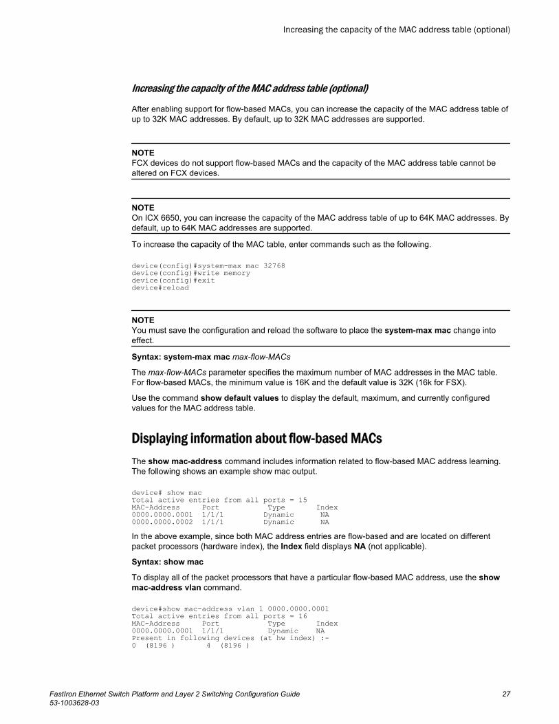
Increasing the capacity of the MAC address table (optional)
After enabling support for flow-based MACs, you can increase the capacity of the MAC address table ofup to 32K MAC addresses. By default, up to 32K MAC addresses are supported.
NOTEFCX devices do not support flow-based MACs and the capacity of the MAC address table cannot bealtered on FCX devices.
NOTEOn ICX 6650, you can increase the capacity of the MAC address table of up to 64K MAC addresses. Bydefault, up to 64K MAC addresses are supported.
To increase the capacity of the MAC table, enter commands such as the following.
device(config)#system-max mac 32768device(config)#write memorydevice(config)#exitdevice#reload
NOTEYou must save the configuration and reload the software to place the system-max mac change intoeffect.
Syntax: system-max mac max-flow-MACs
The max-flow-MACs parameter specifies the maximum number of MAC addresses in the MAC table.For flow-based MACs, the minimum value is 16K and the default value is 32K (16k for FSX).
Use the command show default values to display the default, maximum, and currently configuredvalues for the MAC address table.
Displaying information about flow-based MACsThe show mac-address command includes information related to flow-based MAC address learning.The following shows an example show mac output.
device# show macTotal active entries from all ports = 15MAC-Address Port Type Index0000.0000.0001 1/1/1 Dynamic NA0000.0000.0002 1/1/1 Dynamic NAIn the above example, since both MAC address entries are flow-based and are located on differentpacket processors (hardware index), the Index field displays NA (not applicable).
Syntax: show mac
To display all of the packet processors that have a particular flow-based MAC address, use the showmac-address vlan command.
device#show mac-address vlan 1 0000.0000.0001Total active entries from all ports = 16MAC-Address Port Type Index0000.0000.0001 1/1/1 Dynamic NAPresent in following devices (at hw index) :-0 (8196 ) 4 (8196 )
Increasing the capacity of the MAC address table (optional)
FastIron Ethernet Switch Platform and Layer 2 Switching Configuration Guide 2753-1003628-03
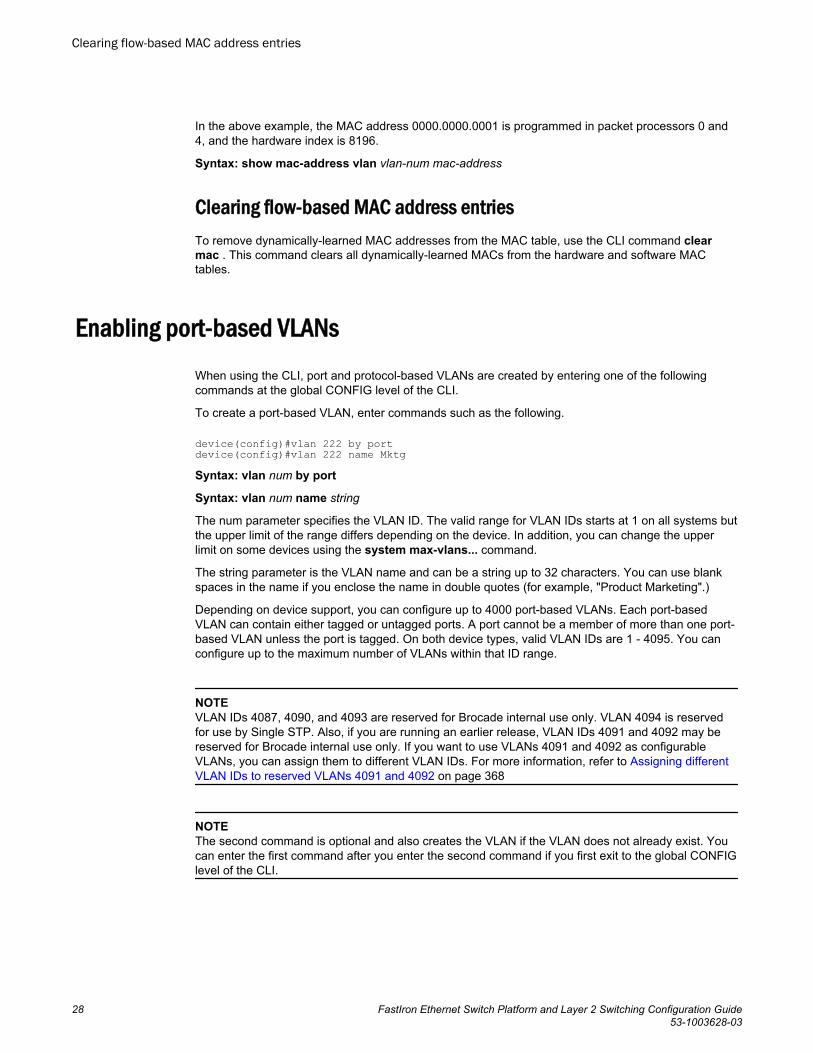
In the above example, the MAC address 0000.0000.0001 is programmed in packet processors 0 and4, and the hardware index is 8196.
Syntax: show mac-address vlan vlan-num mac-address
Clearing flow-based MAC address entriesTo remove dynamically-learned MAC addresses from the MAC table, use the CLI command clearmac . This command clears all dynamically-learned MACs from the hardware and software MACtables.
Enabling port-based VLANs
When using the CLI, port and protocol-based VLANs are created by entering one of the followingcommands at the global CONFIG level of the CLI.
To create a port-based VLAN, enter commands such as the following.
device(config)#vlan 222 by portdevice(config)#vlan 222 name MktgSyntax: vlan num by port
Syntax: vlan num name string
The num parameter specifies the VLAN ID. The valid range for VLAN IDs starts at 1 on all systems butthe upper limit of the range differs depending on the device. In addition, you can change the upperlimit on some devices using the system max-vlans... command.
The string parameter is the VLAN name and can be a string up to 32 characters. You can use blankspaces in the name if you enclose the name in double quotes (for example, "Product Marketing".)
Depending on device support, you can configure up to 4000 port-based VLANs. Each port-basedVLAN can contain either tagged or untagged ports. A port cannot be a member of more than one port-based VLAN unless the port is tagged. On both device types, valid VLAN IDs are 1 - 4095. You canconfigure up to the maximum number of VLANs within that ID range.
NOTEVLAN IDs 4087, 4090, and 4093 are reserved for Brocade internal use only. VLAN 4094 is reservedfor use by Single STP. Also, if you are running an earlier release, VLAN IDs 4091 and 4092 may bereserved for Brocade internal use only. If you want to use VLANs 4091 and 4092 as configurableVLANs, you can assign them to different VLAN IDs. For more information, refer to Assigning differentVLAN IDs to reserved VLANs 4091 and 4092 on page 368
NOTEThe second command is optional and also creates the VLAN if the VLAN does not already exist. Youcan enter the first command after you enter the second command if you first exit to the global CONFIGlevel of the CLI.
Clearing flow-based MAC address entries
28 FastIron Ethernet Switch Platform and Layer 2 Switching Configuration Guide53-1003628-03
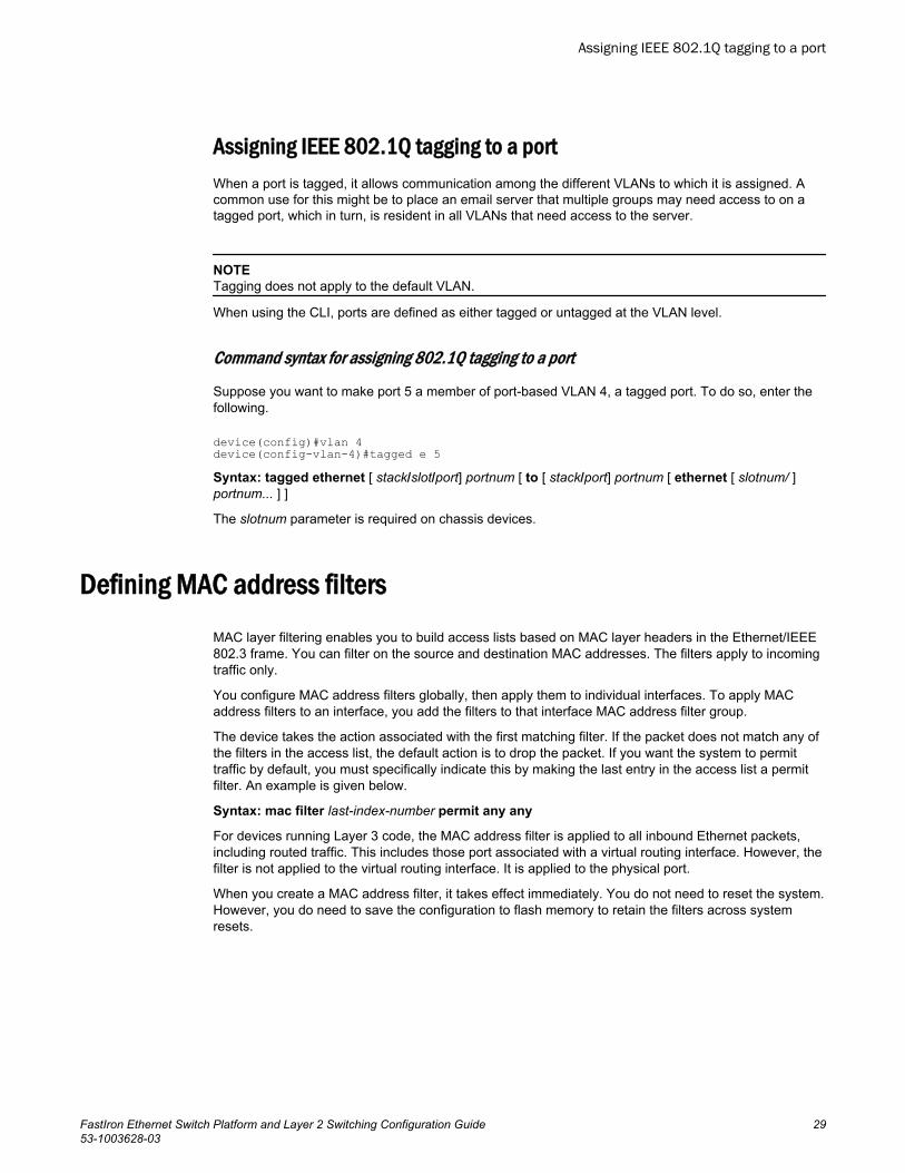
Assigning IEEE 802.1Q tagging to a portWhen a port is tagged, it allows communication among the different VLANs to which it is assigned. Acommon use for this might be to place an email server that multiple groups may need access to on atagged port, which in turn, is resident in all VLANs that need access to the server.
NOTETagging does not apply to the default VLAN.
When using the CLI, ports are defined as either tagged or untagged at the VLAN level.
Command syntax for assigning 802.1Q tagging to a port
Suppose you want to make port 5 a member of port-based VLAN 4, a tagged port. To do so, enter thefollowing.
device(config)#vlan 4device(config-vlan-4)#tagged e 5Syntax: tagged ethernet [ stack/slot/port] portnum [ to [ stack/port] portnum [ ethernet [ slotnum/ ]portnum... ] ]
The slotnum parameter is required on chassis devices.
Defining MAC address filters
MAC layer filtering enables you to build access lists based on MAC layer headers in the Ethernet/IEEE802.3 frame. You can filter on the source and destination MAC addresses. The filters apply to incomingtraffic only.
You configure MAC address filters globally, then apply them to individual interfaces. To apply MACaddress filters to an interface, you add the filters to that interface MAC address filter group.
The device takes the action associated with the first matching filter. If the packet does not match any ofthe filters in the access list, the default action is to drop the packet. If you want the system to permittraffic by default, you must specifically indicate this by making the last entry in the access list a permitfilter. An example is given below.
Syntax: mac filter last-index-number permit any any
For devices running Layer 3 code, the MAC address filter is applied to all inbound Ethernet packets,including routed traffic. This includes those port associated with a virtual routing interface. However, thefilter is not applied to the virtual routing interface. It is applied to the physical port.
When you create a MAC address filter, it takes effect immediately. You do not need to reset the system.However, you do need to save the configuration to flash memory to retain the filters across systemresets.
Assigning IEEE 802.1Q tagging to a port
FastIron Ethernet Switch Platform and Layer 2 Switching Configuration Guide 2953-1003628-03
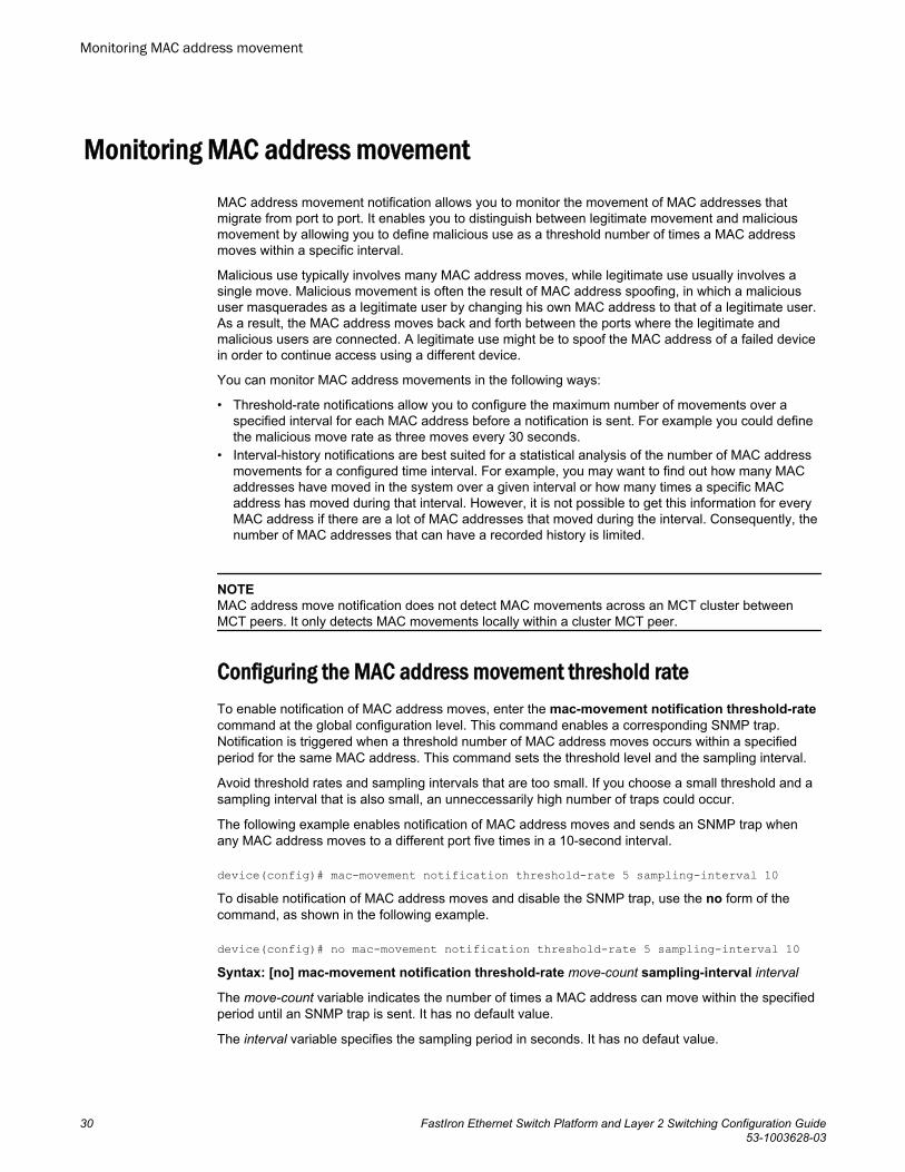
Monitoring MAC address movementMAC address movement notification allows you to monitor the movement of MAC addresses thatmigrate from port to port. It enables you to distinguish between legitimate movement and maliciousmovement by allowing you to define malicious use as a threshold number of times a MAC addressmoves within a specific interval.
Malicious use typically involves many MAC address moves, while legitimate use usually involves asingle move. Malicious movement is often the result of MAC address spoofing, in which a malicioususer masquerades as a legitimate user by changing his own MAC address to that of a legitimate user.As a result, the MAC address moves back and forth between the ports where the legitimate andmalicious users are connected. A legitimate use might be to spoof the MAC address of a failed devicein order to continue access using a different device.
You can monitor MAC address movements in the following ways:
• Threshold-rate notifications allow you to configure the maximum number of movements over aspecified interval for each MAC address before a notification is sent. For example you could definethe malicious move rate as three moves every 30 seconds.
• Interval-history notifications are best suited for a statistical analysis of the number of MAC addressmovements for a configured time interval. For example, you may want to find out how many MACaddresses have moved in the system over a given interval or how many times a specific MACaddress has moved during that interval. However, it is not possible to get this information for everyMAC address if there are a lot of MAC addresses that moved during the interval. Consequently, thenumber of MAC addresses that can have a recorded history is limited.
NOTEMAC address move notification does not detect MAC movements across an MCT cluster betweenMCT peers. It only detects MAC movements locally within a cluster MCT peer.
Configuring the MAC address movement threshold rateTo enable notification of MAC address moves, enter the mac-movement notification threshold-ratecommand at the global configuration level. This command enables a corresponding SNMP trap.Notification is triggered when a threshold number of MAC address moves occurs within a specifiedperiod for the same MAC address. This command sets the threshold level and the sampling interval.
Avoid threshold rates and sampling intervals that are too small. If you choose a small threshold and asampling interval that is also small, an unneccessarily high number of traps could occur.
The following example enables notification of MAC address moves and sends an SNMP trap whenany MAC address moves to a different port five times in a 10-second interval.
device(config)# mac-movement notification threshold-rate 5 sampling-interval 10To disable notification of MAC address moves and disable the SNMP trap, use the no form of thecommand, as shown in the following example.
device(config)# no mac-movement notification threshold-rate 5 sampling-interval 10Syntax: [no] mac-movement notification threshold-rate move-count sampling-interval interval
The move-count variable indicates the number of times a MAC address can move within the specifiedperiod until an SNMP trap is sent. It has no default value.
The interval variable specifies the sampling period in seconds. It has no defaut value.
Monitoring MAC address movement
30 FastIron Ethernet Switch Platform and Layer 2 Switching Configuration Guide53-1003628-03
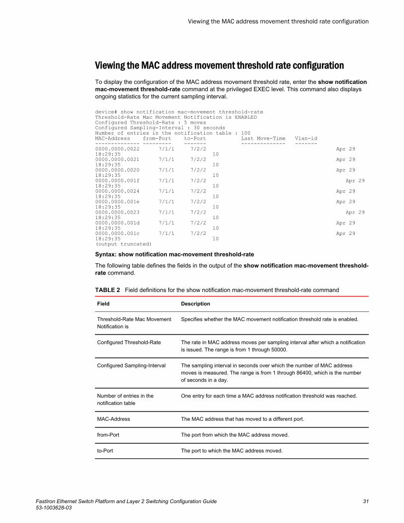
Viewing the MAC address movement threshold rate configurationTo display the configuration of the MAC address movement threshold rate, enter the show notificationmac-movement threshold-rate command at the privileged EXEC level. This command also displaysongoing statistics for the current sampling interval.
device# show notification mac-movement threshold-rateThreshold-Rate Mac Movement Notification is ENABLEDConfigured Threshold-Rate : 5 movesConfigured Sampling-Interval : 30 secondsNumber of entries in the notification table : 100MAC-Address from-Port to-Port Last Move-Time Vlan-id-------------- --------- ------- -------------- -------0000.0000.0022 7/1/1 7/2/2 Apr 29 18:29:35 100000.0000.0021 7/1/1 7/2/2 Apr 29 18:29:35 100000.0000.0020 7/1/1 7/2/2 Apr 29 18:29:35 100000.0000.001f 7/1/1 7/2/2 Apr 29 18:29:35 100000.0000.0024 7/1/1 7/2/2 Apr 29 18:29:35 100000.0000.001e 7/1/1 7/2/2 Apr 29 18:29:35 100000.0000.0023 7/1/1 7/2/2 Apr 29 18:29:35 100000.0000.001d 7/1/1 7/2/2 Apr 29 18:29:35 100000.0000.001c 7/1/1 7/2/2 Apr 29 18:29:35 10(output truncated)Syntax: show notification mac-movement threshold-rate
The following table defines the fields in the output of the show notification mac-movement threshold-rate command.
Field definitions for the show notification mac-movement threshold-rate command TABLE 2
Field Description
Threshold-Rate Mac MovementNotification is
Specifies whether the MAC movement notification threshold rate is enabled.
Configured Threshold-Rate The rate in MAC address moves per sampling interval after which a notificationis issued. The range is from 1 through 50000.
Configured Sampling-Interval The sampling interval in seconds over which the number of MAC addressmoves is measured. The range is from 1 through 86400, which is the numberof seconds in a day.
Number of entries in thenotification table
One entry for each time a MAC address notification threshold was reached.
MAC-Address The MAC address that has moved to a different port.
from-Port The port from which the MAC address moved.
to-Port The port to which the MAC address moved.
Viewing the MAC address movement threshold rate configuration
FastIron Ethernet Switch Platform and Layer 2 Switching Configuration Guide 3153-1003628-03
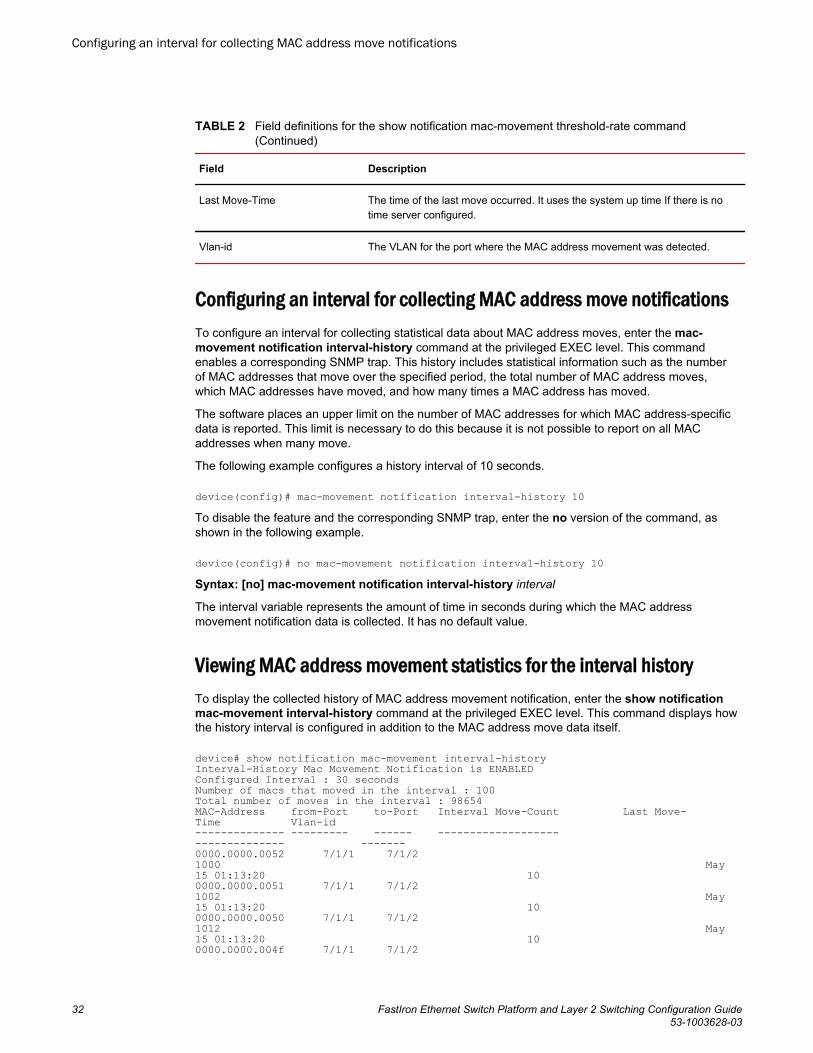
Field definitions for the show notification mac-movement threshold-rate command(Continued)
TABLE 2
Field Description
Last Move-Time The time of the last move occurred. It uses the system up time If there is notime server configured.
Vlan-id The VLAN for the port where the MAC address movement was detected.
Configuring an interval for collecting MAC address move notificationsTo configure an interval for collecting statistical data about MAC address moves, enter the mac-movement notification interval-history command at the privileged EXEC level. This commandenables a corresponding SNMP trap. This history includes statistical information such as the numberof MAC addresses that move over the specified period, the total number of MAC address moves,which MAC addresses have moved, and how many times a MAC address has moved.
The software places an upper limit on the number of MAC addresses for which MAC address-specificdata is reported. This limit is necessary to do this because it is not possible to report on all MACaddresses when many move.
The following example configures a history interval of 10 seconds.
device(config)# mac-movement notification interval-history 10To disable the feature and the corresponding SNMP trap, enter the no version of the command, asshown in the following example.
device(config)# no mac-movement notification interval-history 10Syntax: [no] mac-movement notification interval-history interval
The interval variable represents the amount of time in seconds during which the MAC addressmovement notification data is collected. It has no default value.
Viewing MAC address movement statistics for the interval historyTo display the collected history of MAC address movement notification, enter the show notificationmac-movement interval-history command at the privileged EXEC level. This command displays howthe history interval is configured in addition to the MAC address move data itself.
device# show notification mac-movement interval-historyInterval-History Mac Movement Notification is ENABLEDConfigured Interval : 30 secondsNumber of macs that moved in the interval : 100Total number of moves in the interval : 98654MAC-Address from-Port to-Port Interval Move-Count Last Move-Time Vlan-id-------------- --------- ------ ------------------- -------------- -------0000.0000.0052 7/1/1 7/1/2 1000 May 15 01:13:20 100000.0000.0051 7/1/1 7/1/2 1002 May 15 01:13:20 100000.0000.0050 7/1/1 7/1/2 1012 May 15 01:13:20 100000.0000.004f 7/1/1 7/1/2
Configuring an interval for collecting MAC address move notifications
32 FastIron Ethernet Switch Platform and Layer 2 Switching Configuration Guide53-1003628-03
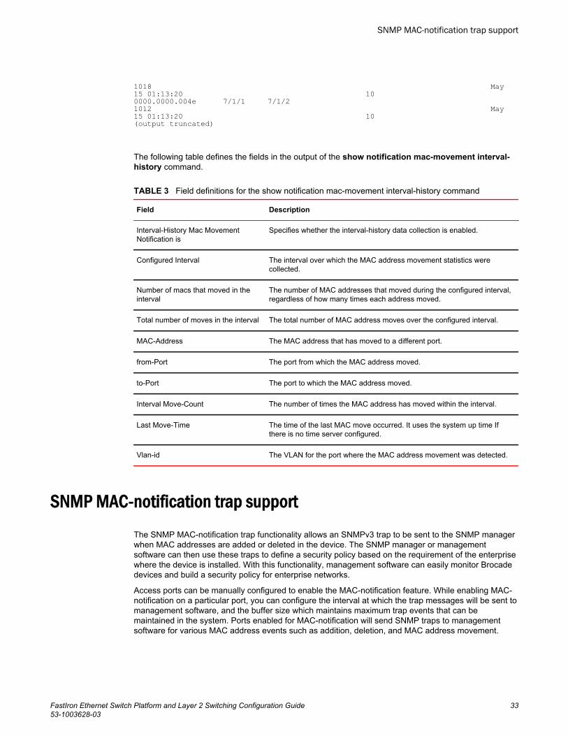
1018 May 15 01:13:20 100000.0000.004e 7/1/1 7/1/2 1012 May 15 01:13:20 10(output truncated)
The following table defines the fields in the output of the show notification mac-movement interval-history command.
Field definitions for the show notification mac-movement interval-history command TABLE 3
Field Description
Interval-History Mac MovementNotification is
Specifies whether the interval-history data collection is enabled.
Configured Interval The interval over which the MAC address movement statistics werecollected.
Number of macs that moved in theinterval
The number of MAC addresses that moved during the configured interval,regardless of how many times each address moved.
Total number of moves in the interval The total number of MAC address moves over the configured interval.
MAC-Address The MAC address that has moved to a different port.
from-Port The port from which the MAC address moved.
to-Port The port to which the MAC address moved.
Interval Move-Count The number of times the MAC address has moved within the interval.
Last Move-Time The time of the last MAC move occurred. It uses the system up time Ifthere is no time server configured.
Vlan-id The VLAN for the port where the MAC address movement was detected.
SNMP MAC-notification trap supportThe SNMP MAC-notification trap functionality allows an SNMPv3 trap to be sent to the SNMP managerwhen MAC addresses are added or deleted in the device. The SNMP manager or managementsoftware can then use these traps to define a security policy based on the requirement of the enterprisewhere the device is installed. With this functionality, management software can easily monitor Brocadedevices and build a security policy for enterprise networks.
Access ports can be manually configured to enable the MAC-notification feature. While enabling MAC-notification on a particular port, you can configure the interval at which the trap messages will be sent tomanagement software, and the buffer size which maintains maximum trap events that can bemaintained in the system. Ports enabled for MAC-notification will send SNMP traps to managementsoftware for various MAC address events such as addition, deletion, and MAC address movement.
SNMP MAC-notification trap support
FastIron Ethernet Switch Platform and Layer 2 Switching Configuration Guide 3353-1003628-03
The access devices in an enterprise network typically connect to the end host, and MAC-notificationcan be deployed on such devices on the access port only. An access port by definition is a port thatconnects to an end host and typically does not result in a network loop.
Requirements and limitations for MAC-notification trap supportThe following requirements and limitations apply to MAC-notification trap support:
• MAC-notification is only supported on access ports.• The network administrator must ensure that there are no loops in the ports enabled for MAC-
notification, because high volume and frequent MAC address movement is not expected on theaccess port.
• The expected MAC scaling with the MAC-notification functionality is 800 MAC addresses persystem, on the access ports where it is enabled. An extra buffer queue size is reserved to absorbany burst.
• The MAC-notification could be bursty in nature. This could be due to a set of hosts that could join ata specific time or a security policy change that could move a set of MAC addresses from one VLANto another. Such bursty events need to be queued, resulting in delayed notifications to themanagement software.
• The number of events that can be queued is finite.• All queued events are notified during the notification interval. The notification interval should be
tuned based on the requirements of the enterprise. However, a very aggressive timer coupled withbursty traffic could load the system and result in a loss of MAC-notification events.
• Static and control MAC events are not considered for MAC-notification event generation.• MAC-notification is supported at an interface level on a device. When enabled, each MAC address
addition or deletion is logged as an event in a buffer-queue.• MAC-notification is currently not supported on MCT (Multi Chassis Trunking).
Configuring SNMP traps for MAC-notificationThe MAC-notification functionality is enabled by default when the device boots up. To configure theMAC-notification functionality on the device, follow these steps:
1. Use the mac-notification interval command with the specified interval value to enable MAC-notification.
2. Use the interface ethernet command with the specified Ethernet interface to enable MAC-notification on the individual interface.
3. Use the snmp-server enable traps mac-notification command to enable MAC-notification on thespecified interface.
4. Use the system-max mac-notification-buffer command to change the value of the MAC-notification buffer size.
Requirements and limitations for MAC-notification trap support
34 FastIron Ethernet Switch Platform and Layer 2 Switching Configuration Guide53-1003628-03
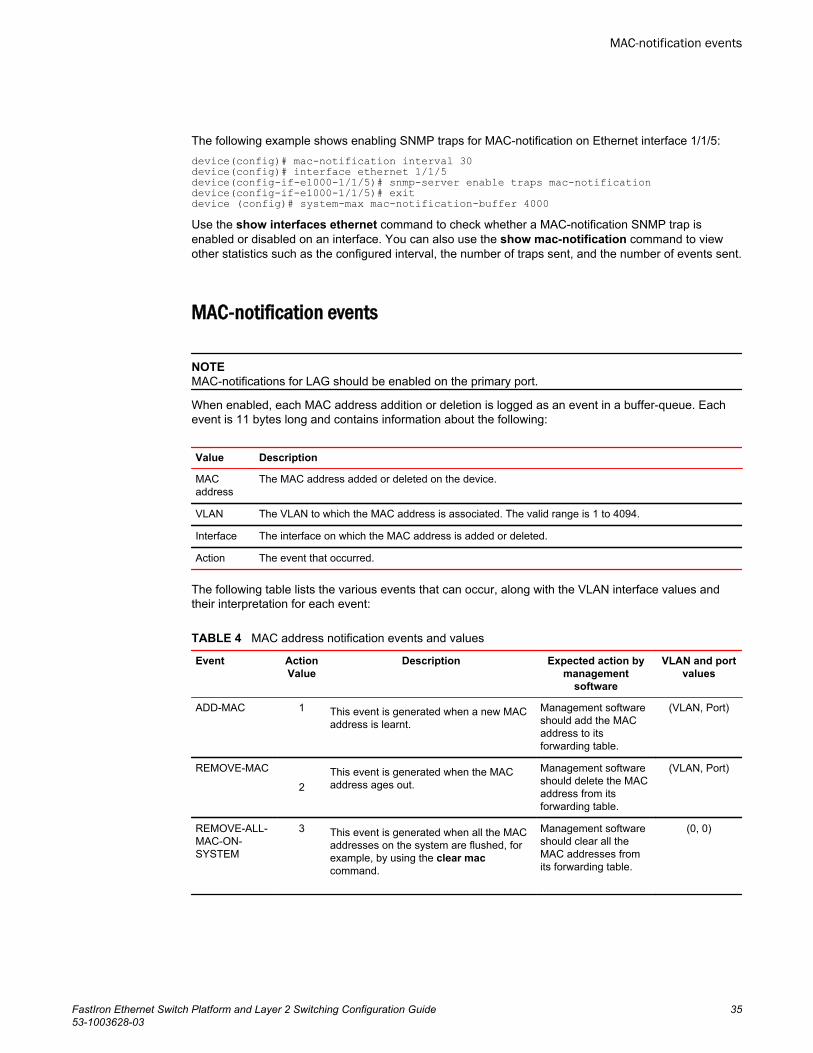
The following example shows enabling SNMP traps for MAC-notification on Ethernet interface 1/1/5:device(config)# mac-notification interval 30device(config)# interface ethernet 1/1/5device(config-if-e1000-1/1/5)# snmp-server enable traps mac-notificationdevice(config-if-e1000-1/1/5)# exitdevice (config)# system-max mac-notification-buffer 4000Use the show interfaces ethernet command to check whether a MAC-notification SNMP trap isenabled or disabled on an interface. You can also use the show mac-notification command to viewother statistics such as the configured interval, the number of traps sent, and the number of events sent.
MAC-notification events
NOTEMAC-notifications for LAG should be enabled on the primary port.
When enabled, each MAC address addition or deletion is logged as an event in a buffer-queue. Eachevent is 11 bytes long and contains information about the following:
Value Description
MACaddress
The MAC address added or deleted on the device.
VLAN The VLAN to which the MAC address is associated. The valid range is 1 to 4094.
Interface The interface on which the MAC address is added or deleted.
Action The event that occurred.
The following table lists the various events that can occur, along with the VLAN interface values andtheir interpretation for each event:
MAC address notification events and valuesTABLE 4
Event ActionValue
Description Expected action bymanagement
software
VLAN and portvalues
ADD-MAC 1 This event is generated when a new MACaddress is learnt.
Management softwareshould add the MACaddress to itsforwarding table.
(VLAN, Port)
REMOVE-MAC
2This event is generated when the MACaddress ages out.
Management softwareshould delete the MACaddress from itsforwarding table.
(VLAN, Port)
REMOVE-ALL-MAC-ON-SYSTEM
3 This event is generated when all the MACaddresses on the system are flushed, forexample, by using the clear maccommand.
Management softwareshould clear all theMAC addresses fromits forwarding table.
(0, 0)
MAC-notification events
FastIron Ethernet Switch Platform and Layer 2 Switching Configuration Guide 3553-1003628-03
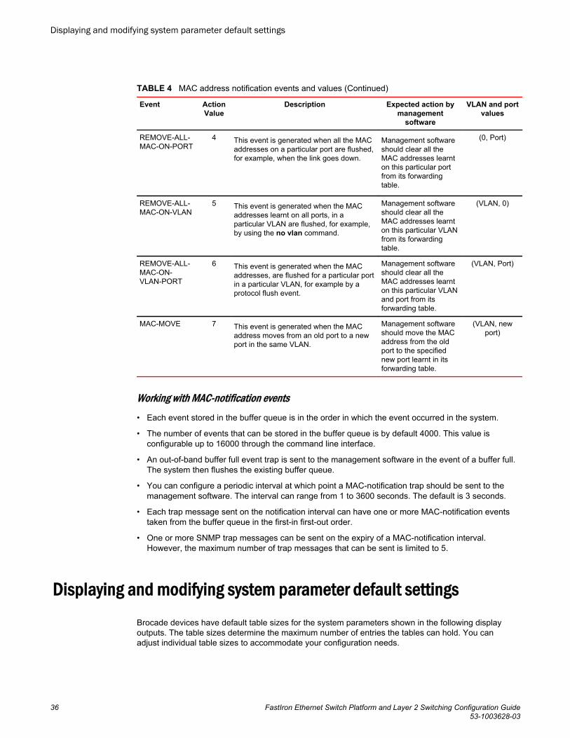
MAC address notification events and values (Continued)TABLE 4
Event ActionValue
Description Expected action bymanagement
software
VLAN and portvalues
REMOVE-ALL-MAC-ON-PORT
4 This event is generated when all the MACaddresses on a particular port are flushed,for example, when the link goes down.
Management softwareshould clear all theMAC addresses learnton this particular portfrom its forwardingtable.
(0, Port)
REMOVE-ALL-MAC-ON-VLAN
5 This event is generated when the MACaddresses learnt on all ports, in aparticular VLAN are flushed, for example,by using the no vlan command.
Management softwareshould clear all theMAC addresses learnton this particular VLANfrom its forwardingtable.
(VLAN, 0)
REMOVE-ALL-MAC-ON-VLAN-PORT
6 This event is generated when the MACaddresses, are flushed for a particular portin a particular VLAN, for example by aprotocol flush event.
Management softwareshould clear all theMAC addresses learnton this particular VLANand port from itsforwarding table.
(VLAN, Port)
MAC-MOVE 7 This event is generated when the MACaddress moves from an old port to a newport in the same VLAN.
Management softwareshould move the MACaddress from the oldport to the specifiednew port learnt in itsforwarding table.
(VLAN, newport)
Working with MAC-notification events• Each event stored in the buffer queue is in the order in which the event occurred in the system.
• The number of events that can be stored in the buffer queue is by default 4000. This value isconfigurable up to 16000 through the command line interface.
• An out-of-band buffer full event trap is sent to the management software in the event of a buffer full.The system then flushes the existing buffer queue.
• You can configure a periodic interval at which point a MAC-notification trap should be sent to themanagement software. The interval can range from 1 to 3600 seconds. The default is 3 seconds.
• Each trap message sent on the notification interval can have one or more MAC-notification eventstaken from the buffer queue in the first-in first-out order.
• One or more SNMP trap messages can be sent on the expiry of a MAC-notification interval.However, the maximum number of trap messages that can be sent is limited to 5.
Displaying and modifying system parameter default settingsBrocade devices have default table sizes for the system parameters shown in the following displayoutputs. The table sizes determine the maximum number of entries the tables can hold. You canadjust individual table sizes to accommodate your configuration needs.
Displaying and modifying system parameter default settings
36 FastIron Ethernet Switch Platform and Layer 2 Switching Configuration Guide53-1003628-03
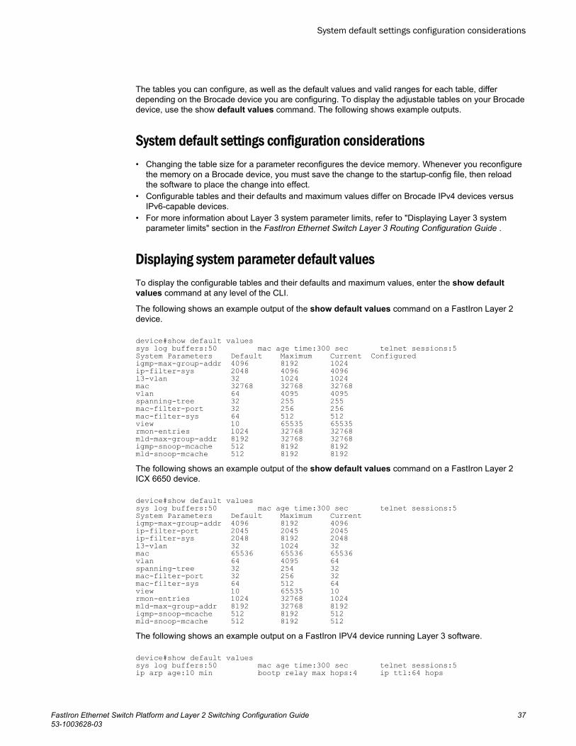
The tables you can configure, as well as the default values and valid ranges for each table, differdepending on the Brocade device you are configuring. To display the adjustable tables on your Brocadedevice, use the show default values command. The following shows example outputs.
System default settings configuration considerations• Changing the table size for a parameter reconfigures the device memory. Whenever you reconfigure
the memory on a Brocade device, you must save the change to the startup-config file, then reloadthe software to place the change into effect.
• Configurable tables and their defaults and maximum values differ on Brocade IPv4 devices versusIPv6-capable devices.
• For more information about Layer 3 system parameter limits, refer to "Displaying Layer 3 systemparameter limits" section in the FastIron Ethernet Switch Layer 3 Routing Configuration Guide .
Displaying system parameter default valuesTo display the configurable tables and their defaults and maximum values, enter the show defaultvalues command at any level of the CLI.
The following shows an example output of the show default values command on a FastIron Layer 2device.
device#show default valuessys log buffers:50 mac age time:300 sec telnet sessions:5System Parameters Default Maximum Current Configuredigmp-max-group-addr 4096 8192 1024ip-filter-sys 2048 4096 4096l3-vlan 32 1024 1024mac 32768 32768 32768vlan 64 4095 4095spanning-tree 32 255 255mac-filter-port 32 256 256mac-filter-sys 64 512 512view 10 65535 65535rmon-entries 1024 32768 32768mld-max-group-addr 8192 32768 32768igmp-snoop-mcache 512 8192 8192mld-snoop-mcache 512 8192 8192The following shows an example output of the show default values command on a FastIron Layer 2ICX 6650 device.
device#show default valuessys log buffers:50 mac age time:300 sec telnet sessions:5System Parameters Default Maximum Current igmp-max-group-addr 4096 8192 4096 ip-filter-port 2045 2045 2045 ip-filter-sys 2048 8192 2048 l3-vlan 32 1024 32 mac 65536 65536 65536 vlan 64 4095 64 spanning-tree 32 254 32 mac-filter-port 32 256 32 mac-filter-sys 64 512 64 view 10 65535 10 rmon-entries 1024 32768 1024 mld-max-group-addr 8192 32768 8192 igmp-snoop-mcache 512 8192 512 mld-snoop-mcache 512 8192 512 The following shows an example output on a FastIron IPV4 device running Layer 3 software.
device#show default valuessys log buffers:50 mac age time:300 sec telnet sessions:5ip arp age:10 min bootp relay max hops:4 ip ttl:64 hops
System default settings configuration considerations
FastIron Ethernet Switch Platform and Layer 2 Switching Configuration Guide 3753-1003628-03
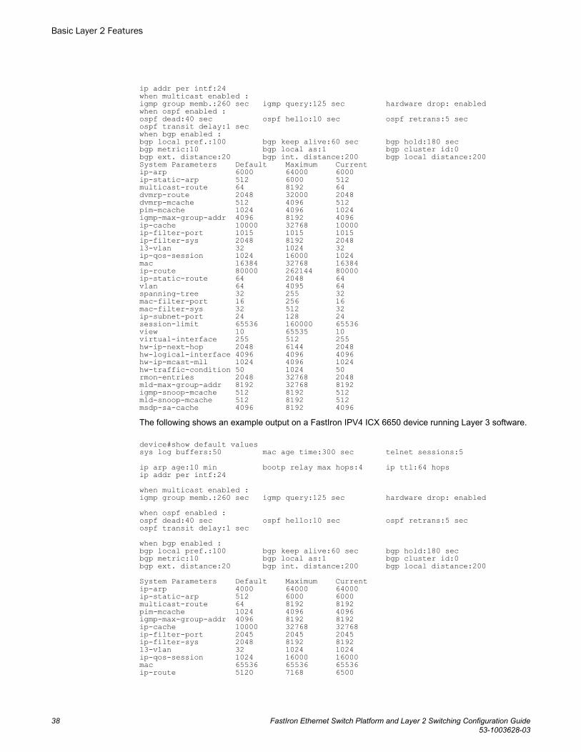
ip addr per intf:24when multicast enabled :igmp group memb.:260 sec igmp query:125 sec hardware drop: enabledwhen ospf enabled :ospf dead:40 sec ospf hello:10 sec ospf retrans:5 secospf transit delay:1 secwhen bgp enabled :bgp local pref.:100 bgp keep alive:60 sec bgp hold:180 secbgp metric:10 bgp local as:1 bgp cluster id:0bgp ext. distance:20 bgp int. distance:200 bgp local distance:200System Parameters Default Maximum Currentip-arp 6000 64000 6000ip-static-arp 512 6000 512multicast-route 64 8192 64dvmrp-route 2048 32000 2048dvmrp-mcache 512 4096 512pim-mcache 1024 4096 1024igmp-max-group-addr 4096 8192 4096ip-cache 10000 32768 10000ip-filter-port 1015 1015 1015ip-filter-sys 2048 8192 2048l3-vlan 32 1024 32ip-qos-session 1024 16000 1024mac 16384 32768 16384ip-route 80000 262144 80000ip-static-route 64 2048 64vlan 64 4095 64spanning-tree 32 255 32mac-filter-port 16 256 16mac-filter-sys 32 512 32ip-subnet-port 24 128 24session-limit 65536 160000 65536view 10 65535 10virtual-interface 255 512 255hw-ip-next-hop 2048 6144 2048hw-logical-interface 4096 4096 4096hw-ip-mcast-mll 1024 4096 1024hw-traffic-condition 50 1024 50rmon-entries 2048 32768 2048mld-max-group-addr 8192 32768 8192igmp-snoop-mcache 512 8192 512mld-snoop-mcache 512 8192 512msdp-sa-cache 4096 8192 4096The following shows an example output on a FastIron IPV4 ICX 6650 device running Layer 3 software.
device#show default valuessys log buffers:50 mac age time:300 sec telnet sessions:5 ip arp age:10 min bootp relay max hops:4 ip ttl:64 hops ip addr per intf:24 when multicast enabled : igmp group memb.:260 sec igmp query:125 sec hardware drop: enabled when ospf enabled : ospf dead:40 sec ospf hello:10 sec ospf retrans:5 sec ospf transit delay:1 sec when bgp enabled : bgp local pref.:100 bgp keep alive:60 sec bgp hold:180 sec bgp metric:10 bgp local as:1 bgp cluster id:0 bgp ext. distance:20 bgp int. distance:200 bgp local distance:200 System Parameters Default Maximum Current ip-arp 4000 64000 64000 ip-static-arp 512 6000 6000 multicast-route 64 8192 8192 pim-mcache 1024 4096 4096 igmp-max-group-addr 4096 8192 8192 ip-cache 10000 32768 32768 ip-filter-port 2045 2045 2045 ip-filter-sys 2048 8192 8192 l3-vlan 32 1024 1024 ip-qos-session 1024 16000 16000 mac 65536 65536 65536 ip-route 5120 7168 6500
Basic Layer 2 Features
38 FastIron Ethernet Switch Platform and Layer 2 Switching Configuration Guide53-1003628-03
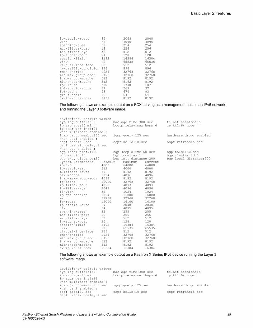
ip-static-route 64 2048 2048 vlan 64 4095 4095 spanning-tree 32 254 254 mac-filter-port 16 256 256 mac-filter-sys 32 512 512 ip-subnet-port 24 128 128 session-limit 8192 16384 16384 view 10 65535 65535 virtual-interface 255 512 512 hw-traffic-condition 896 896 896 rmon-entries 1024 32768 32768 mld-max-group-addr 8192 32768 32768 igmp-snoop-mcache 512 8192 8192 mld-snoop-mcache 512 8192 8192 ip6-route 580 1348 187 ip6-static-route 37 269 37 ip6-cache 93 674 93 gre-tunnels 16 64 64 hw-ip-route-tcam 8192 8192 8192The following shows an example output on a FCX serving as a management host in an IPv6 networkand running the Layer 3 software image.
device#show default valuessys log buffers:50 mac age time:300 sec telnet sessions:5ip arp age:10 min bootp relay max hops:4 ip ttl:64 hopsip addr per intf:24when multicast enabled :igmp group memb.:260 sec igmp query:125 sec hardware drop: enabledwhen ospf enabled :ospf dead:40 sec ospf hello:10 sec ospf retrans:5 secospf transit delay:1 secwhen bgp enabled :bgp local pref.:100 bgp keep alive:60 sec bgp hold:180 secbgp metric:10 bgp local as:1 bgp cluster id:0bgp ext. distance:20 bgp int. distance:200 bgp local distance:200System Parameters Default Maximum Currentip-arp 4000 64000 64000ip-static-arp 512 6000 6000multicast-route 64 8192 8192pim-mcache 1024 4096 4096igmp-max-group-addr 4096 8192 8192ip-cache 10000 32768 32768ip-filter-port 4093 4093 4093ip-filter-sys 2048 4096 4096l3-vlan 32 1024 1024ip-qos-session 1024 16000 16000mac 32768 32768 32768ip-route 12000 16100 16100ip-static-route 64 2048 2048vlan 64 4095 4095spanning-tree 32 255 255mac-filter-port 16 256 256mac-filter-sys 32 512 512ip-subnet-port 24 128 128session-limit 8192 16384 16384view 10 65535 65535virtual-interface 255 512 512rmon-entries 1024 32768 32768mld-max-group-addr 8192 32768 32768igmp-snoop-mcache 512 8192 8192mld-snoop-mcache 512 8192 8192hw-ip-route-tcam 16384 16384 16384The following shows an example output on a FastIron X Series IPv6 device running the Layer 3software image.
device#show default valuessys log buffers:50 mac age time:300 sec telnet sessions:5ip arp age:10 min bootp relay max hops:4 ip ttl:64 hopsip addr per intf:24when multicast enabled :igmp group memb.:260 sec igmp query:125 sec hardware drop: enabledwhen ospf enabled :ospf dead:40 sec ospf hello:10 sec ospf retrans:5 secospf transit delay:1 sec
Basic Layer 2 Features
FastIron Ethernet Switch Platform and Layer 2 Switching Configuration Guide 3953-1003628-03

when bgp enabled :bgp local pref.:100 bgp keep alive:60 sec bgp hold:180 secbgp metric:10 bgp local as:1 bgp cluster id:0bgp ext. distance:20 bgp int. distance:200 bgp local distance:200System Parameters Default Maximum Currentip-arp 6000 64000 64000ip-static-arp 512 6000 6000multicast-route 64 8192 8192dvmrp-route 2048 32000 32000dvmrp-mcache 512 4096 4096pim-mcache 1024 4096 4096igmp-max-group-addr 4096 8192 8192ip-cache 10000 32768 32768ip-filter-port 1015 1015 1015ip-filter-sys 2048 8192 4096l3-vlan 32 1024 1024ip-qos-session 1024 16000 16000mac 16384 32768 32768ip-route 262144 524288 524288ip-static-route 64 2048 2048vlan 64 4095 4095spanning-tree 32 255 255mac-filter-port 16 256 256mac-filter-sys 32 512 512ip-subnet-port 24 128 128session-limit 65536 160000 65537view 10 65535 65535virtual-interface 255 512 512hw-ip-next-hop 2048 6144 2481hw-traffic-condition 50 1024 52rmon-entries 2048 32768 32768mld-max-group-addr 8192 32768 32768igmp-snoop-mcache 512 8192 8192mld-snoop-mcache 512 8192 8192ip6-route 32768 65536 65536ip6-static-route 64 512 512ip6-cache 65536 131072 131072msdp-sa-cache 4096 8192 8192gre-tunnels 16 64 64The following shows an example output on a ICX 7750 device.device# show default valuessys log buffers:50 mac age time:300 sec telnet sessions:5ip arp age:10 min bootp relay max hops:4 ip ttl:64 hopsip addr per intf:24when multicast enabled :igmp group memb.:260 sec igmp query:125 sec hardware drop: enabledwhen ospf enabled :ospf dead:40 sec ospf hello:10 sec ospf retrans:5 secospf transit delay:1 secwhen bgp enabled :bgp local pref.:100 bgp keep alive:60 sec bgp hold:180 secbgp metric:10 bgp local as:1 bgp cluster id:0bgp ext. distance:20 bgp int. distance:200 bgp local distance:200System Parameters Default Maximum Current Configuredip-arp 8192 64000 64000 64000ip-static-arp 512 1024 512 512ip-cache 8192 32768 32768 32768ip-filter-port 2047 2047 2047 2047ip-filter-sys 3072 8192 3072 3072l3-vlan 32 1024 32 32ip-qos-session 1024 16000 1024 1024mac 32768 32768 32768 32768ip-route 98304 131072 98304 98304ip-static-route 64 2048 64 64vlan 64 4095 4095 4095spanning-tree 128 254 254 254mac-filter-port 32 256 32 32mac-filter-sys 64 512 64 64ip-subnet-port 24 128 24 24session-limit 65536 160000 65536 65536view 10 65535 10 10
Basic Layer 2 Features
40 FastIron Ethernet Switch Platform and Layer 2 Switching Configuration Guide53-1003628-03
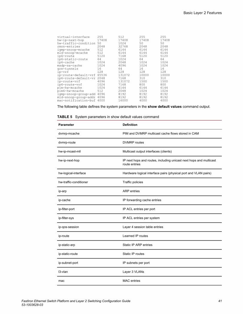
virtual-interface 255 512 255 255hw-ip-next-hop 17408 17408 17408 17408hw-traffic-condition 50 1024 50 50rmon-entries 2048 32768 2048 2048igmp-snoop-mcache 512 6144 6144 6144mld-snoop-mcache 512 6144 6144 6144ip6-route 5120 7168 5120 5120ip6-static-route 64 1024 64 64ip6-cache 1024 2048 1024 1024msdp-sa-cache 1024 4096 1024 1024gre-tunnels 16 64 16 16ip-vrf 128 128 128 128ip-route-default-vrf 65536 131072 10000 10000ip6-route-default-vr 2048 7168 310 310ip-route-vrf 4096 131072 1500 1500ip6-route-vrf 1024 7168 800 800pim-hw-mcache 1024 6144 6144 6144pim6-hw-mcache 512 2048 1024 1024igmp-snoop-group-add 4096 8192 8192 8192mld-snoop-group-addr 4096 8192 8192 8192mac-notification-buf 4000 16000 4000 4000The following table defines the system parameters in the show default values command output.
System parameters in show default values command TABLE 5
Parameter Definition
dvmrp-mcache PIM and DVMRP multicast cache flows stored in CAM
dvmrp-route DVMRP routes
hw-ip-mcast-mll Multicast output interfaces (clients)
hw-ip-next-hop IP next hops and routes, including unicast next hops and multicastroute entries
hw-logical-interface Hardware logical interface pairs (physical port and VLAN pairs)
hw-traffic-conditioner Traffic policies
ip-arp ARP entries
ip-cache IP forwarding cache entries
ip-filter-port IP ACL entries per port
ip-filter-sys IP ACL entries per system
ip-qos-session Layer 4 session table entries
ip-route Learned IP routes
ip-static-arp Static IP ARP entries
ip-static-route Static IP routes
ip-subnet-port IP subnets per port
l3-vlan Layer 3 VLANs
mac MAC entries
Basic Layer 2 Features
FastIron Ethernet Switch Platform and Layer 2 Switching Configuration Guide 4153-1003628-03
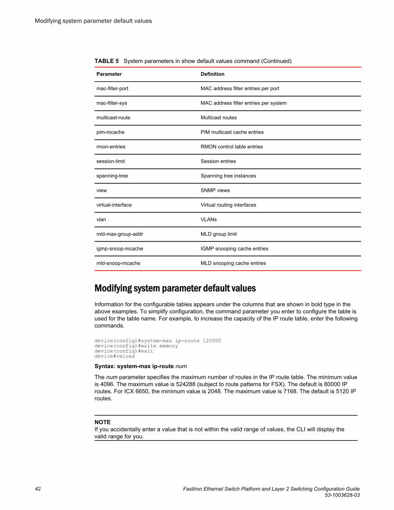
System parameters in show default values command (Continued)TABLE 5
Parameter Definition
mac-filter-port MAC address filter entries per port
mac-filter-sys MAC address filter entries per system
multicast-route Multicast routes
pim-mcache PIM multicast cache entries
rmon-entries RMON control table entries
session-limit Session entries
spanning-tree Spanning tree instances
view SNMP views
virtual-interface Virtual routing interfaces
vlan VLANs
mld-max-group-addr MLD group limit
igmp-snoop-mcache IGMP snooping cache entries
mld-snoop-mcache MLD snooping cache entries
Modifying system parameter default valuesInformation for the configurable tables appears under the columns that are shown in bold type in theabove examples. To simplify configuration, the command parameter you enter to configure the table isused for the table name. For example, to increase the capacity of the IP route table, enter the followingcommands.
device(config)#system-max ip-route 120000device(config)#write memorydevice(config)#exitdevice#reloadSyntax: system-max ip-route num
The num parameter specifies the maximum number of routes in the IP route table. The minimum valueis 4096. The maximum value is 524288 (subject to route patterns for FSX). The default is 80000 IProutes. For ICX 6650, the minimum value is 2048. The maximum value is 7168. The default is 5120 IProutes.
NOTEIf you accidentally enter a value that is not within the valid range of values, the CLI will display thevalid range for you.
Modifying system parameter default values
42 FastIron Ethernet Switch Platform and Layer 2 Switching Configuration Guide53-1003628-03
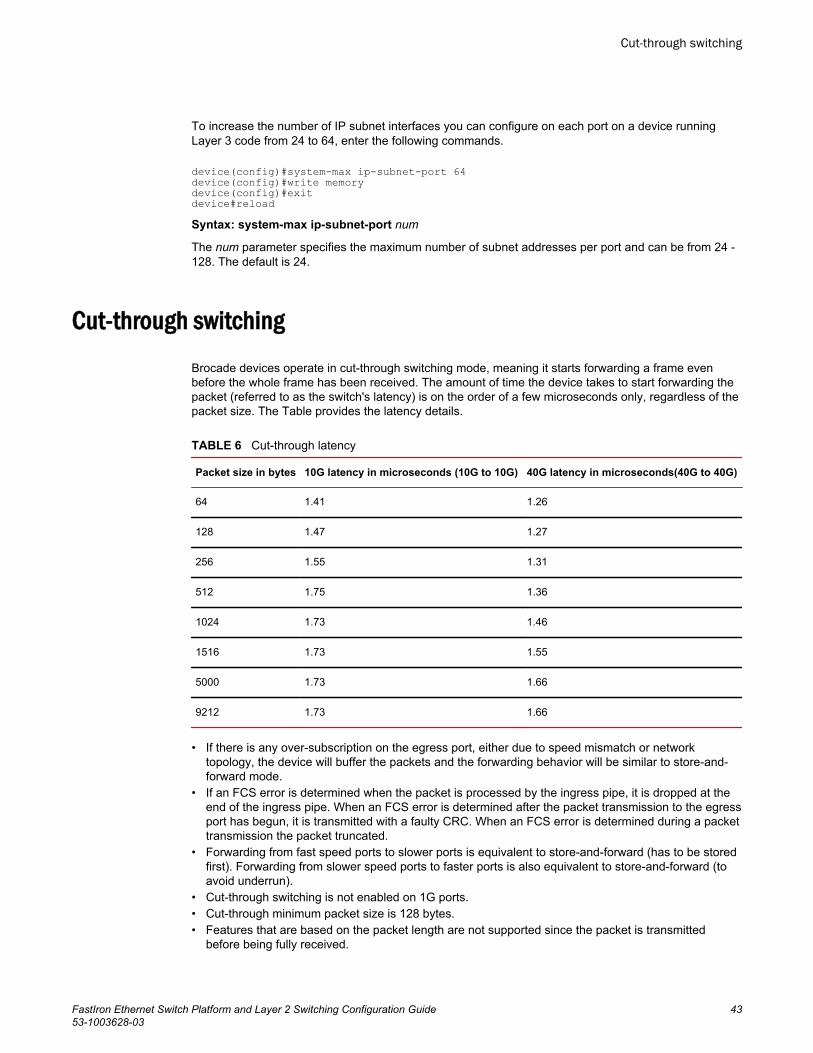
To increase the number of IP subnet interfaces you can configure on each port on a device runningLayer 3 code from 24 to 64, enter the following commands.
device(config)#system-max ip-subnet-port 64device(config)#write memorydevice(config)#exitdevice#reloadSyntax: system-max ip-subnet-port num
The num parameter specifies the maximum number of subnet addresses per port and can be from 24 -128. The default is 24.
Cut-through switchingBrocade devices operate in cut-through switching mode, meaning it starts forwarding a frame evenbefore the whole frame has been received. The amount of time the device takes to start forwarding thepacket (referred to as the switch's latency) is on the order of a few microseconds only, regardless of thepacket size. The Table provides the latency details.
Cut-through latency TABLE 6
Packet size in bytes 10G latency in microseconds (10G to 10G) 40G latency in microseconds(40G to 40G)
64 1.41 1.26
128 1.47 1.27
256 1.55 1.31
512 1.75 1.36
1024 1.73 1.46
1516 1.73 1.55
5000 1.73 1.66
9212 1.73 1.66
• If there is any over-subscription on the egress port, either due to speed mismatch or networktopology, the device will buffer the packets and the forwarding behavior will be similar to store-and-forward mode.
• If an FCS error is determined when the packet is processed by the ingress pipe, it is dropped at theend of the ingress pipe. When an FCS error is determined after the packet transmission to the egressport has begun, it is transmitted with a faulty CRC. When an FCS error is determined during a packettransmission the packet truncated.
• Forwarding from fast speed ports to slower ports is equivalent to store-and-forward (has to be storedfirst). Forwarding from slower speed ports to faster ports is also equivalent to store-and-forward (toavoid underrun).
• Cut-through switching is not enabled on 1G ports.• Cut-through minimum packet size is 128 bytes.• Features that are based on the packet length are not supported since the packet is transmitted
before being fully received.
Cut-through switching
FastIron Ethernet Switch Platform and Layer 2 Switching Configuration Guide 4353-1003628-03
Dynamic buffer allocation for QoS priorities for FastIron X Seriesdevices
NOTEThis section applies to FastIron X Series devices only. To configure dynamic buffer limits BrocadeFCX Series, and ICX devices, refer to Dynamic buffer allocation for FCX and ICX devices on page48.
By default, Brocade IronWare software allocates a certain number of buffers to the outbound transmitqueue for each port, based on QoS priority (traffic class). The buffers control the total number ofpackets permitted in the outbound transmit queue for the port. For each port, the Brocade devicedefines the maximum outbound transmit buffers, also called queue depth limits , as follows:
• Total Transmit Queue Depth Limit - The total maximum number of transmit buffers allocated for alloutbound packets on a port. Packets are added to the port's outbound queue as long as the numberof buffers currently in use is less than the total transmit queue depth limit. When this limit isreached, any new packets attempting to enter the port’s transmit queue will be dropped until at leastone buffer is freed.
• Transmit Queue Depth Limit for a Given Traffic Class - The maximum number of transmit buffersallocated for packets with a given traffic class (0 through 7) on a port. Packets with the specifiedtraffic class are added to the port’s outbound queue as long as the number of buffers currently inuse for that traffic class is less than the transmit queue depth limit for the traffic class. When thislimit is reached, any new packets with the specified traffic class attempting to enter the port’stransmit queue will be dropped.
Except for the third-generation Interface modules, you can increase or decrease both of these queuedepth limits per port. On the SX-FI48GPP, SX-FI-24GPP, SX-FI-24HF, SX-FI-2XG or SX-FI-8XGmodules, to increase or decrease the queue depth limits for a port, you configure a buffer profile andthen apply it to the port. A buffer profile can be tied to one or more ports. Therefore, if you change theconfiguration on one port, it will change the configuration on all ports associated with the same bufferprofile.
Dynamic buffer allocation for QoS is useful in situations where applications have intermittent bursts ofoversubscription. For example, by increasing the buffers on the egress port, the Brocade device will beable to forward oversubscribed packets instead of dropping them.
Default queue depth limits for FastIron X Series devicesThe following table defines the default maximum queue depth values per port, per traffic class. TheBrocade device drops the packets that cause the port to exceed these limits.
NOTEThe SX-FI48GPP Interface module supports 48 tri-speed (10/100/1000) ports. When the ports areconfigured at lower speeds, for example, 100 Mbps or 10 Mbps, the maximum queue depth is lessthan 256 when egress congestion occurs at the front-end Network Processor (NP) of the SX-FI48GPPmodule. If egress congestion occurs at the back-end NP of the SX-FI48GPP module, the maximumqueue depth is 4095. The limit for buffer sharing is 4088.
Dynamic buffer allocation for QoS priorities for FastIron X Series devices
44 FastIron Ethernet Switch Platform and Layer 2 Switching Configuration Guide53-1003628-03
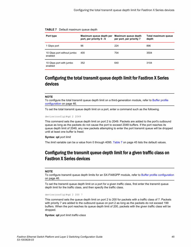
Default maximum queue depthTABLE 7
Port type Maximum queue depth perport, per priority 0 - 6
Maximum queue depthper port, per priority 7
Total maximum queuedepth
1 Gbps port 96 224 896
10 Gbps port without jumboenabled
400 704 3504
10 Gbps port with jumboenabled
352 640 3104
Configuring the total transmit queue depth limit for FastIron X Seriesdevices
NOTETo configure the total transmit queue depth limit on a third-generation module, refer to Buffer profileconfiguration on page 46.
To set the total transmit queue depth limit on a port, enter a command such as the following.
device(config)#qd 2 2049This command sets the queue depth limit on port 2 to 2049. Packets are added to the port's outboundqueue as long as the packets do not cause the port to exceed 2048 buffers. If the port reaches itsqueue depth limit of 2049, any new packets attempting to enter the port transmit queue will be droppeduntil at least one buffer is freed.
Syntax: qd port limit
The limit variable can be a value from 0 through 4095. Table 7 on page 45 lists the default values.
Configuring the transmit queue depth limit for a given traffic class onFastIron X Series devices
NOTETo configure transmit queue depth limits for an SX-FI48GPP module, refer to Buffer profile configurationon page 46.
To set the transmit queue depth limit on a port for a given traffic class, first enter the transmit queuedepth limit for the traffic class, and then specify the traffic class.
device(config)#qd 2 200 7This command sets the queue depth limit on port 2 to 200 for packets with a traffic class of 7. Packetswith priority 7 are added to the outbound queue on port 2 as long as the packets do not exceed 199buffers. When the port reaches its queue depth limit of 200, packets with the given traffic class will bedropped.
Syntax: qd port limit traffic-class
Configuring the total transmit queue depth limit for FastIron X Series devices
FastIron Ethernet Switch Platform and Layer 2 Switching Configuration Guide 4553-1003628-03
The limit variable can be a value from 0 through 4095 and cannot exceed the total transmit queuedepth limit configured for the port. Table 7 on page 45 lists the default values.
The sum of the queue depth limits for individual traffic classes on a port does not need to equal thetotal queue depth limit for the port:
• If the sum of the individual traffic class queue depth limits exceeds the total port limit and the totalport limit is reached, any buffer that gets released can be used by any traffic class queue that hasnot reached its individual limit.
• If the sum of the individual traffic class queue depth limits is less than the total port limit, theremaining buffers can be used only by packets with a priority of 7.
The traffic-class variable can be a value from 0 through 7, where 7 is the highest priority queue.
Removing buffer allocation limits on FastIron X Series devicesYou can remove buffer allocation limits on all ports and all Traffic Classes globally. This permits allavailable buffers in a port region to be used in a first-come-first-serve basis by any of its ports,regardless of priority. This can be done using the following command.
device(config)#buffer-sharing-fullSyntax: [no] buffer-sharing-full
The buffer-sharing-full command sets the total transmit queue depth limit and the transmit queuedepth limits for each Traffic Class to 4095 for all ports of the device. The command overrides anyexisting individually configured queue depth limits.
ATTENTION
The buffer-sharing-full command should be used carefully. By entering this command, there is nolimit on the number of buffers a port or a specific priority on a port can use. One port could potentiallyuse up all the available buffers of its port region and cause starvation on other ports of the port region.
Buffer profile configurationThe following Interface modules support up to eight buffer profiles:
• SX-FI48GPP• SX-FI-24GPP• SX-FI-24HF• SX-FI-2XG• SX-FI-8XG
A buffer profile defines the total transmit queue depth limit for a port and the transmit queue depth limitfor a given traffic class . On the listed supported Interface modules, each port is associated with abuffer profile. In contrast, Interface modules other than the SX-FI-48GPP, SX-FI-24GPP, SX-FI24-HF,SX-FI-2XG, and the SX-FI-8XG support the configuration of transmit queue depth limits per port.
By default, each port on an SX-FI48GPP, SX-FI-24GPP, SX-FI-24HF, SX-FI-2XG or SX-FI-8XGInterface module is associated with buffer profile ID 1. Profile 0 is reserved for buffer sharing. Defaultqueue depth limits are provided in Default queue depth limits for FastIron X Series devices on page44. To change the queue depth limit for a port on the supported Interface modules, configure a bufferprofile ID that is different from the default or configured value, and apply the buffer profile to the port.When you change the queue depth limit on a port, the configuration will apply to all ports associatedwith the same buffer profile ID. For example, if ports 1/1 through 1/5 are associated with buffer profile
Removing buffer allocation limits on FastIron X Series devices
46 FastIron Ethernet Switch Platform and Layer 2 Switching Configuration Guide53-1003628-03
ID 3 and you enter the qd 1/1 1000 command, the queue depth limit of 1000 will apply to ports 1/1through 1/5.
NOTEIn the case of SX-FI48GPP module, the queue depth configured using the qd command is notapplicable when the port is set to speeds lower than 1Gbps. The qd command is applicable only whenthe port is set to speeds greater than 1Gbps.
Configuring a buffer profile and defining the queue depth limits
1. Create a buffer profile and assign it to a port. For example, to create buffer profile 2 and assign it toport 1/1, enter the following command.
device(config)#qd 1/1 profile-id 2Syntax: [no] qd slotnum/portnum profile-id number
The number variable specifies the buffer profile ID associated with the slotnum / portnum . The bufferprofile ID can be a number from 1 through 7. Profile 0 is reserved for buffer sharing.
2. Configure the total transmit queue depth limit associated with the buffer profile. For example, tochange the total transmit queue depth limit for buffer profile 2 to 1000, enter the following command.
device(config)#qd 1/1 1000Because port 1/1 is associated with buffer profile 2, this command sets the queue depth limit forbuffer profile 2 to 1000. Packets are added to the outbound queue of a port as long as the packets donot cause the port to exceed 1000 buffers. If the port reaches its queue depth limit of 1000, any newpackets attempting to enter the transmit queue will be dropped until at least one buffer is freed.
Syntax: [no] qd slotnum/portnum limit
The limit variable can be a value from 0 through 4095. The default is 4095.3. If desired, configure the queue depth limit for a given traffic class. For example, to change the queue
depth limit for buffer profile 2 to 300 for packets with a traffic class of 1, enter the following command.
device(config)#qd 1/1 300 1For ports that use buffer profile 2, packets with priority 1 are added to the outbound queue as long asthe packets do not exceed 299 buffers. When the port reaches its queue depth limit of 300, packetswith the given traffic class will be dropped.
Syntax: [no] qd slotnum/portnum limit traffic-class
The limit variable can be a value from 0 through 4095 and cannot exceed the total transmit queuedepth limit configured in the previous step.
The sum of the queue depth limits for individual traffic classes on a port does not need to equal thetotal queue depth limit for the port:
• If the sum of the individual traffic class queue depth limits exceeds the total port limit and the totalport limit is reached, any buffer that gets released can be used by any traffic class queue that hasnot reached its individual limit.
• If the sum of the individual traffic class queue depth limits is less than the total port limit, theremaining buffers can be used only by packets with a priority of 7.
The traffic-class variable can be a value from 0 through 7, where 7 is the highest priority queue.4. Enter the write memory command to save the configuration.
Configuring a buffer profile and defining the queue depth limits
FastIron Ethernet Switch Platform and Layer 2 Switching Configuration Guide 4753-1003628-03
Displaying the buffer profile configuration
To display the buffer profile configuration for an SX-FI48GPP Interface module, use the showconfiguration command.
The following example shows that buffer profile 2 and its configured queue depth values apply to ports1/1 and 1/2. Although the profile configuration was changed for port 1/1 only, port 1/2 has alsochanged to match the configuration.
device(config)#show configurationqd 1/1 profile-id 2qd 1/2 profile-id 2!qd 1/1 1000qd 1/2 1000qd 1/1 300 1qd 1/2 300 1Syntax: show configuration
Default queue depth limits for FastIron X Series devicesTable 7 on page 45 defines the default maximum queue depth values per port, per traffic class. TheBrocade device drops the packets that cause the port to exceed these limits.
NOTEThe SX-FI48GPP Interface module supports 48 tri-speed (10/100/1000) ports. When the ports areconfigured at lower speeds, for example 100 Mbps or 10 Mbps, the maximum queue depth is less than256 when egress congestion occurs at the front-end Network Processor (NP) of the SX-FI48GPPmodule. If egress congestion occurs at the back-end NP of the SX-FI48GPP module, the maximumqueue depth is 4095. The limit for buffer sharing is 4088.
Dynamic buffer allocation for FCX and ICX devicesBy default, the traditional stack architecture allocates fixed buffers on a per-priority queue, per-packetprocessor basis. The buffers control the total number of packets that can be queued in the outboundtransmit for the port. In instances of heavy traffic bursts to aggregation links, such as in stackingconfigurations or mixed-speed environments, momentary oversubscription of the buffers anddescriptors may occur. A descriptor points to one or more packet buffers.
Brocade FastIron stackable devices provide the capability to allocate additional egress buffering anddescriptors to handle momentary bursty traffic periods, especially when other priority queues may notbe in use, or may not be experiencing heavy traffic. This allows users to allocate and fine-tune thedepth of priority buffer queues for each packet processor.
Configuring buffer profilesThere are two different methods of allocating buffers and descriptors to the ports and its queues.
One method uses the qd-descriptor and qd-buffer CLI commands to allocate descriptors and buffers,respectively, to the port and its queues. This method is available on FCX and ICX devices.
The other method uses user-configurable buffer profiles. This method allows you to define a templateof buffer allocations to be used on a per-port per-queue basis on the devices. When applied, this
Displaying the buffer profile configuration
48 FastIron Ethernet Switch Platform and Layer 2 Switching Configuration Guide53-1003628-03
buffer profile acts as if you created a series of the qd commands. This buffer profile is a simpler form ofallocating descriptors and buffers to the port and its queues. This method is available on FCX and ICXdevices.
Configuring buffer profiles with qd-descriptor and qd-buffer commands on FCX and ICX devices
The 48-port Brocade stackable switch has two packet processors. The 24-port Brocade stackableswitch has a single packet processor. For devices in a traditional stack, each stack unit has thepossibility of two packet processors, but the second processor for a 24-port stack unit cannot beconfigured. The number of actual available packet processors depends on the type and number ofswitches in the stack.
For example, for an 8-unit stack of 48 ports, the packet processor numbering scheme is as follows:
• Stack unit 1 - Packet processors 0 and 1• Stack unit 2 - Packet processors 2 and 3• Stack unit 3 - Packet processors 4 and 5• Stack unit 4 - Packet processors 6 and 7• Stack unit 5 - Packet processors 8 and 9• Stack unit 6 - Packet processors 10 and 11• Stack unit 7 - Packet processors 12 and 13• Stack unit 8 - Packet processors 14 and 15
In this configuration, if stack unit 3 and stack unit 7 are 24-port devices, the odd-numbered packetprocessors 5 and 13 cannot be configured, and do not exist, although they are reserved.
Configuration steps for buffer profile with qd-descriptor and qd-buffer commands onFCX and ICX
The descriptor and buffer allocation process occurs in four sequential steps using the qd-buffer andqd-descriptor commands.
NOTEFor FCX devices, when you reset buffer values for the 10 Gbps ports, the buffer values for the rear-panel 10 Gbps and16 Gbps ports are also reset.
1. Configure the allowable port descriptors. Port descriptors set the limit for the ports. The minimum limitfor the port descriptors is 16. The maximum limit of the port descriptors depends on the hardwaredevice. Port descriptor limits of different platforms are listed in the section Buffer and descriptormaximum and default allocation values on page 54. Configure the allowable port descriptors byentering a command similar to the following.
device# qd-descriptor 1 2 76Syntax: [no] qd-descriptor devicenum porttypeval numdescriptors
The devicenum variable refers to the device in the stacking unit. The device number starts from 0.
The porttypeval variable is 1 for 1 Gbps ports and 2 for 10 Gbps ports.
The numdescriptors variable refers to the number of descriptors to allocate.2. Configure the queue descriptors. The minimum limit for queue descriptors is 16. The system default
queue descriptors for different platforms are listed in Buffer and descriptor maximum and defaultallocation values on page 54. Configure the queue descriptors for the queue by entering acommand similar to the following.
device# qd-descriptor 1 2 76 2
Configuring buffer profiles with qd-descriptor and qd-buffer commands on FCX and ICX devices
FastIron Ethernet Switch Platform and Layer 2 Switching Configuration Guide 4953-1003628-03
Syntax: [no] qd-descriptor devicenum porttypeval numdescriptors priorityqueue
The devicenum variable refers to the device in the stacking unit. The device number starts from 0.
The porttypeval variable is 1 for 1 Gbps ports and 2 for 10 Gbps ports.
The numdescriptors variable refers to the number of descriptors to allocate.
The priorityqueue variable refers to the specific queue of the port from 0 through 7.3. Configure the port buffers. The minimum limit for port buffers is 16. The maximum limit for the port
buffer depends on the hardware device. Port buffer limits of different platforms are listed in Bufferand descriptor maximum and default allocation values on page 54. Configure the allowable packetbuffers by entering a command similar to the following.
device# qd-buffer 1 2 76Syntax: [no] qd-buffer devicenum porttypeval numbuffers
The devicenum variable refers to the device in the stacking unit. The device number starts from 0.
The porttypeval variable is 1 for 1 Gbps ports and 2 for 10 Gbps ports.
The numbuffers variable refers to the number of buffers to allocate.4. Configure the queue buffers. The maximum limit of queue buffers depends on the hardware device.
Queue buffer limits of different platforms are listed in Buffer and descriptor maximum and defaultallocation values on page 54. Configure the queue buffers by entering a command similar to thefollowing.
device# qd-buffer 1 2 76 2Syntax: [no] qd-buffer devicenum porttypeval numbuffers priorityqueue
The devicenum variable refers to the device in the stacking unit. The device number starts from 0.
The porttypeval variable is 1 for 1 Gbps ports and 2 for 10 Gbps ports.
The numbuffers variable refers to the number of buffers to allocate.
The priorityqueue variable refers to the specific queue of the port from 0 through 7.
Basic Layer 2 Features
50 FastIron Ethernet Switch Platform and Layer 2 Switching Configuration Guide53-1003628-03
Sample configuration for buffer profile with qd-descriptor and qd-buffer commands on FCX andICX
This sample configuration assumes a four-unit stack with the following topology. Note that there is nopacket processor 3 or 7, because stack units 2 and 4 are 24-port devices.
• Stack unit 1, 48 ports - Packet processor numbers 0 and 1• Stack unit 2, 24 ports - Packet processor number 2• Stack unit 3, 48 ports - Packet processors 4 and 5• Stack unit 4, 24 ports - Packet processor number 6
The following commands allocate available buffers to be used by priority 0 queues in the four-unit stack.
qd-descriptor 0 1 4095qd-descriptor 1 1 4095qd-descriptor 2 1 4095qd-descriptor 4 1 4095qd-descriptor 5 1 4095qd-descriptor 6 1 4095qd-descriptor 0 2 4095qd-descriptor 1 2 4095qd-descriptor 2 2 4095qd-descriptor 4 2 4095qd-descriptor 5 2 4095qd-descriptor 6 2 4095qd-descriptor 0 1 4095 0qd-descriptor 1 1 4095 0qd-descriptor 2 1 4095 0qd-descriptor 4 1 4095 0qd-descriptor 5 1 4095 0qd-descriptor 6 1 4095 0qd-descriptor 0 2 4095 0qd-descriptor 1 2 4095 0qd-descriptor 2 2 4095 0qd-descriptor 4 2 4095 0qd-descriptor 5 2 4095 0qd-descriptor 6 2 4095 0qd-buffer 0 1 4095qd-buffer 1 1 4095qd-buffer 2 1 4095qd-buffer 4 1 4095qd-buffer 5 1 4095qd-buffer 6 1 4095qd-buffer 0 2 4095qd-buffer 1 2 4095qd-buffer 2 2 4095qd-buffer 4 2 4095qd-buffer 5 2 4095qd-buffer 6 2 4095qd-buffer 0 1 4095 0qd-buffer 1 1 4095 0qd-buffer 2 1 4095 0qd-buffer 4 1 4095 0qd-buffer 5 1 4095 0qd-buffer 6 1 4095 0qd-buffer 0 2 4095 0qd-buffer 1 2 4095 0qd-buffer 2 2 4095 0qd-buffer 4 2 4095 0qd-buffer 5 2 4095 0qd-buffer 6 2 4095 0
Configuring user-configurable buffer profiles on FCX and ICX devices
A buffer profile is a mechanism to arbitrarily allocate the egress buffers and descriptors limits to beapplied to a port and its queues. Users can define a limit for a port and its queues by configuring thebuffer profiles on the device. Therefore, user-configurable buffer profiles provide a template to allocateegress buffers and descriptors limits to the port and on its queues. This template is then applied to thedevice.
Configuring user-configurable buffer profiles on FCX and ICX devices
FastIron Ethernet Switch Platform and Layer 2 Switching Configuration Guide 5153-1003628-03
NOTEBuffer profiles can be configured for 10 Gbps and 1 Gbps ports, but not for ICX 6610 40 Gbps ports.The 10 Gbps profile will apply to ICX 6430 and 6450 stacking ports, as well as FCX 16 Gbps stackingports.
Configuring and applying a user-configurable buffer profile is a two-step process.
First, create a user-configurable buffer profile with the qd-buffer-profile CLI command. Define a namefor the user-configurable buffer profile, assign buffer and descriptor limits at the port level, and thendefine buffer and descriptor limits per queue of that port.
Second, apply the user-configurable buffer profile you created to the device with the buffer-profile CLIcommand.
Configuring a user-configurable buffer profile
To configure a user-configurable buffer profile, complete the following steps.
1. Create a user-configurable buffer profile. For example, to create a user-configurable buffer profilenamed profile1 enter the following command.
device(config)# qd-buffer-profile profile1#Syntax: [no] qd-buffer-profile user-profile-name
The user-profile-name variable specifies the name of the user-configurable buffer profile. The profilename can be up to 64 characters long.
2. Configure the port type for the user-configurable buffer profile.
The buffer profile port type can be configured for 1 Gbps ports, 10 Gbps ports, or for all the ports.The port-type option should be in line with the qd-buffer legacy command; that is, 1 for 1 Gbpsports, 2 for 10 Gbps ports, 0 for all the ports. The default port type is set to 1 Gbps. To configure auser-configurable profile for 10 Gbps ports, the 10 Gbps port type must be explicitly provided by theport-type option. Modifications to buffers and descriptors of a port and its queues take effectdynamically.
When the profile type is configured as all 1 Gbps and 10 Gbps ports, the default buffers anddescriptors will be set according to the port type; that is, all 1 Gbps ports use 1 Gbps defaults and10 Gbps ports use 10 Gbps defaults. If you configure a port and its queue with egress buffer anddescriptor limits, then the configured limits are used for both 1 Gbps and 10 Gbps ports.
To configure the port type 1 for the profile named "profile1", enter the following command at theprofile configuration level.
device(qd-profile-profile1)# profile-config port-type 1Syntax: [no] profile-config port-type { 0 | 1 | 2 }
• ‐ 0 -- All 1 Gbps and 10 Gbps ports‐ 1 -- All 1 Gbps ports‐ 2 -- All 10 Gbps ports
NOTEThe no form of the command sets the profile port type to 1 Gbps.
Port type modification resets the profile to its default value. All the port and queue buffers anddescriptors will be set to either 1 Gbps or 10 Gbps defaults as per the configuration, which meansall the user configurations for the port and its queues will be lost.
Basic Layer 2 Features
52 FastIron Ethernet Switch Platform and Layer 2 Switching Configuration Guide53-1003628-03
NOTEPort type modifications on an active profile are not allowed.
3. Configure the port buffers. Port buffer sets the maximum buffer limit for the ports. The maximum limitdepends on the hardware device. Port buffer limits of different platforms are listed in the section Buffer and descriptor maximum and default allocation values on page 54. To configure the portbuffers for the user-configurable buffer profile named "profile1", enter the following command at theprofile configuration level.
device(qd-profile-profile1)# profile-config port-buffer 8000Syntax: profile-config port-buffer decimal
The decimal variable refers to the number of buffers.4. Configure the port descriptors. Port descriptors set the maximum descriptor limit for the ports. The
maximum limit of port descriptors depends on the hardware device. Port descriptor limits of differentplatforms are listed in Buffer and descriptor maximum and default allocation values on page 54. Toconfigure the port descriptors for the user-configurable buffer profile named "profile1", enter thefollowing command at the profile configuration level.
device(qd-profile-profile1)# profile-config port-descriptor 8000Syntax: profile-config port-descriptor decimal
The decimal variable refers to the number of descriptors.5. Configure the queue buffers. Queue buffers set the maximum buffer limit for a specified queue. If a
queue buffer limit is not set, then the default is used. The system default queue buffers for differentplatforms are listed in Buffer and descriptor maximum and default allocation values on page 54. Toconfigure the queue buffers for the user-configurable buffer profile named "profile1", enter thefollowing command at the profile configuration level.
device(qd-profile-profile1)# profile-config queue-buffers 2 600Syntax: profile-config queue-buffers queue-num decimal
The queue-num variable refers to the number of the queue of a port from 0 through 7.
The decimal variable refers to the number of buffers.6. Configure the queue descriptors. Queue descriptors set the maximum descriptor limit for the
specified queue. If a queue descriptors limit is not set, then the default is used. The system defaultqueue descriptors for different platforms are listed in Buffer and descriptor maximum and defaultallocation values on page 54. To configure the queue descriptors for the user-configurable bufferprofile named "profile1", enter the following command at the profile configuration level.
device(qd-profile-profile1)#Profile-config queue-descriptors 2 600Syntax: profile-config queue-descriptors queue-num decimal
The queue-num variable refers to the number of the queue of a port from 0 through 7.
The decimal variable refers to the number of descriptors.
Applying a user-configurable buffer profile on the device
Once configured, a user-configurable buffer profile must be applied on the device. To apply the user-configurable buffer profile named "profile1" to a device, enter the following command.
device(config)# buffer-profile port-region 0 qd-buffer-profile profile1Syntax: [no] buffer-profile port-region port-region qd-buffer-profile user-profile-name
The port-region variable is the device number on which the user-configurable buffer profile is applied.
The user-profile-name variable is the name of the user-configured profile.
Basic Layer 2 Features
FastIron Ethernet Switch Platform and Layer 2 Switching Configuration Guide 5353-1003628-03

Buffer and descriptor maximum and default allocation values
This section lists the maximum and default buffers and descriptors values of a port and its queues oneach hardware platform. The following tables are included:
• Table 8 describes FCX devices.• Table 9 describes ICX 6610 devices.• Table 10 describes ICX 6430 devices.• Table 11 describes ICX 6450 devices.
NOTEValues in the following tables are for software traffic classes (TCs) or QoS priority (qosp) levels.
Port buffers and descriptors values on FCX devices TABLE 8
1 Gbps buffers and descriptors 10 Gbps buffers and descriptors
Port Limit 8096 8096
TC0 512 768
TC1 192 320
TC2 192 320
TC3 192 320
TC4 192 320
TC5 256 384
TC6 256 384
TC7 256 384
NOTEIn FCX devices, the maximum buffer value that can be configured using the qd-buffer command is7955.
Port buffer and descriptors values on ICX 6610 devices TABLE 9
1 Gbps buffers anddescriptors
10 Gbps buffers anddescriptors
40 Gbps buffers anddescriptors
Port Limit 8096 8096 8096
TC0 128 160 256
TC1 32 48 64
TC2 32 48 64
Buffer and descriptor maximum and default allocation values
54 FastIron Ethernet Switch Platform and Layer 2 Switching Configuration Guide53-1003628-03
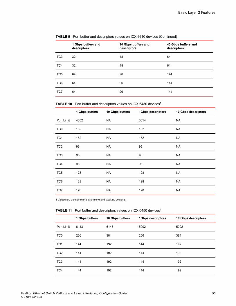
Port buffer and descriptors values on ICX 6610 devices (Continued)TABLE 9
1 Gbps buffers anddescriptors
10 Gbps buffers anddescriptors
40 Gbps buffers anddescriptors
TC3 32 48 64
TC4 32 48 64
TC5 64 96 144
TC6 64 96 144
TC7 64 96 144
Port buffer and descriptors values on ICX 6430 devices1TABLE 10
1 Gbps buffers 10 Gbps buffers 1Gbps descriptors 10 Gbps descriptors
Port Limit 4032 NA 3854 NA
TC0 182 NA 182 NA
TC1 182 NA 182 NA
TC2 96 NA 96 NA
TC3 96 NA 96 NA
TC4 96 NA 96 NA
TC5 128 NA 128 NA
TC6 128 NA 128 NA
TC7 128 NA 128 NA
1 Values are the same for stand-alone and stacking systems.
Port buffer and descriptors values on ICX 6450 devices1TABLE 11
1 Gbps buffers 10 Gbps buffers 1Gbps descriptors 10 Gbps descriptors
Port Limit 6143 6143 5902 5092
TC0 256 384 256 384
TC1 144 192 144 192
TC2 144 192 144 192
TC3 144 192 144 192
TC4 144 192 144 192
Basic Layer 2 Features
FastIron Ethernet Switch Platform and Layer 2 Switching Configuration Guide 5553-1003628-03
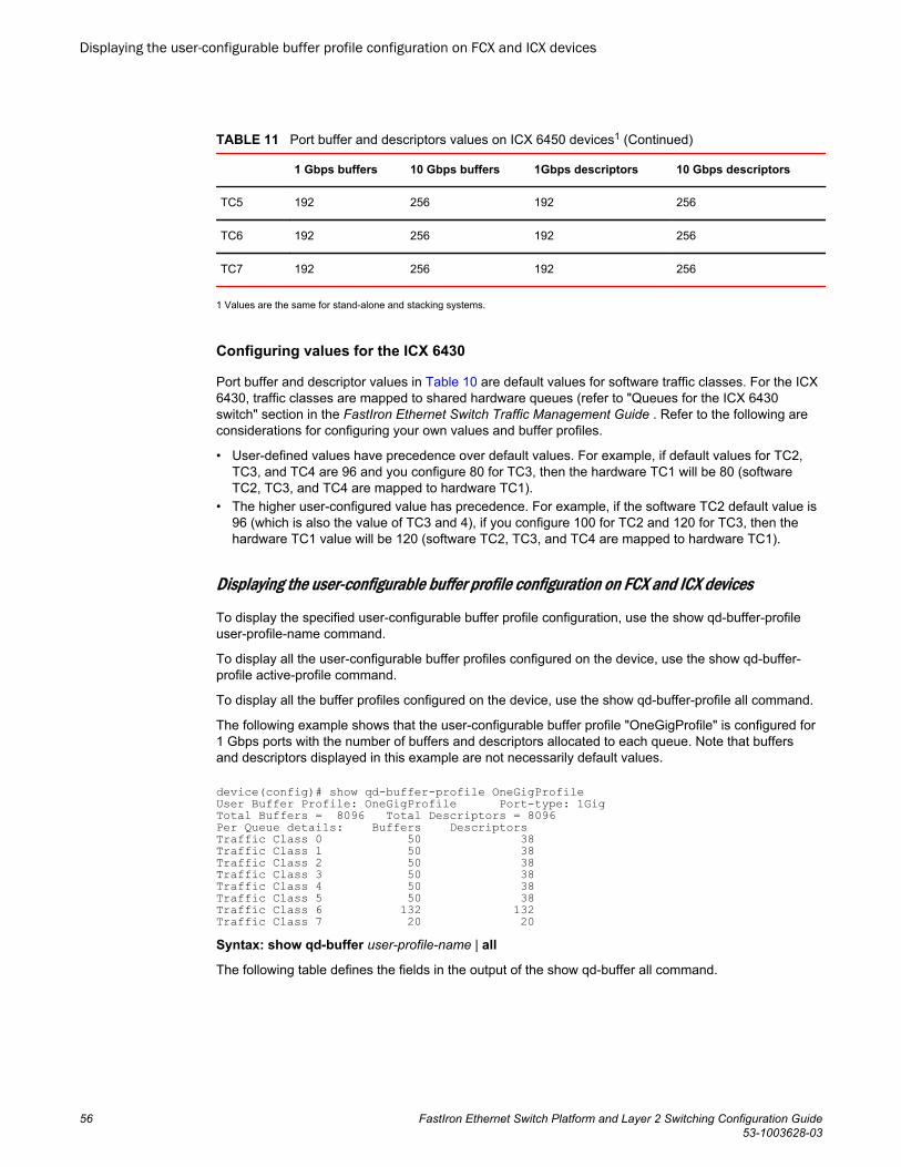
Port buffer and descriptors values on ICX 6450 devices1 (Continued)TABLE 11
1 Gbps buffers 10 Gbps buffers 1Gbps descriptors 10 Gbps descriptors
TC5 192 256 192 256
TC6 192 256 192 256
TC7 192 256 192 256
1 Values are the same for stand-alone and stacking systems.
Configuring values for the ICX 6430
Port buffer and descriptor values in Table 10 are default values for software traffic classes. For the ICX6430, traffic classes are mapped to shared hardware queues (refer to "Queues for the ICX 6430switch" section in the FastIron Ethernet Switch Traffic Management Guide . Refer to the following areconsiderations for configuring your own values and buffer profiles.
• User-defined values have precedence over default values. For example, if default values for TC2,TC3, and TC4 are 96 and you configure 80 for TC3, then the hardware TC1 will be 80 (softwareTC2, TC3, and TC4 are mapped to hardware TC1).
• The higher user-configured value has precedence. For example, if the software TC2 default value is96 (which is also the value of TC3 and 4), if you configure 100 for TC2 and 120 for TC3, then thehardware TC1 value will be 120 (software TC2, TC3, and TC4 are mapped to hardware TC1).
Displaying the user-configurable buffer profile configuration on FCX and ICX devices
To display the specified user-configurable buffer profile configuration, use the show qd-buffer-profileuser-profile-name command.
To display all the user-configurable buffer profiles configured on the device, use the show qd-buffer-profile active-profile command.
To display all the buffer profiles configured on the device, use the show qd-buffer-profile all command.
The following example shows that the user-configurable buffer profile "OneGigProfile" is configured for1 Gbps ports with the number of buffers and descriptors allocated to each queue. Note that buffersand descriptors displayed in this example are not necessarily default values.
device(config)# show qd-buffer-profile OneGigProfileUser Buffer Profile: OneGigProfile Port-type: 1GigTotal Buffers = 8096 Total Descriptors = 8096Per Queue details: Buffers DescriptorsTraffic Class 0 50 38Traffic Class 1 50 38Traffic Class 2 50 38Traffic Class 3 50 38Traffic Class 4 50 38Traffic Class 5 50 38Traffic Class 6 132 132Traffic Class 7 20 20Syntax: show qd-buffer user-profile-name | all
The following table defines the fields in the output of the show qd-buffer all command.
Displaying the user-configurable buffer profile configuration on FCX and ICX devices
56 FastIron Ethernet Switch Platform and Layer 2 Switching Configuration Guide53-1003628-03
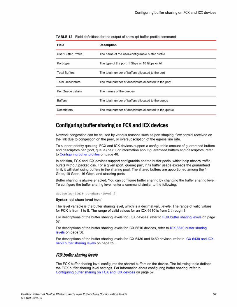
Field definitions for the output of show qd-buffer-profile commandTABLE 12
Field Description
User Buffer Profile The name of the user-configurable buffer profile
Port-type The type of the port: 1 Gbps or 10 Gbps or All
Total Buffers The total number of buffers allocated to the port
Total Descriptors The total number of descriptors allocated to the port
Per Queue details The names of the queues
Buffers The total number of buffers allocated to the queue
Descriptors The total number of descriptors allocated to the queue
Configuring buffer sharing on FCX and ICX devicesNetwork congestion can be caused by various reasons such as port shaping, flow control received onthe link due to congestion on the peer, or oversubscription of the egress line rate.
To support priority queuing, FCX and ICX devices support a configurable amount of guaranteed buffersand descriptors per (port, queue) pair. For information about guaranteed buffers and descriptors, referto Configuring buffer profiles on page 48.
In addition, FCX and ICX devices support configurable shared buffer pools, which help absorb trafficbursts without packet loss. For a given (port, queue) pair, if its buffer usage exceeds the guaranteedlimit, it will start using buffers in the sharing pool. The shared buffers are apportioned among the 1Gbps, 10 Gbps, 16 Gbps, and stacking ports.
Buffer sharing is always enabled. You can configure buffer sharing by changing the buffer sharing level.To configure the buffer sharing level, enter a command similar to the following.
device(config)# qd-share-level 2Syntax: qd-share-level level
The level variable is the buffer sharing level, which is a decimal valu levele. The range of valid valuesfor FCX is from 1 to 8. The range of valid values for an ICX 6610 is from 2 through 8.
For descriptions of the buffer sharing levels for FCX devices, refer to FCX buffer sharing levels on page57.
For descriptions of the buffer sharing levels for ICX 6610 devices, refer to ICX 6610 buffer sharinglevels on page 58.
For descriptions of the buffer sharing levels for ICX 6430 and 6450 devices, refer to ICX 6430 and ICX6450 buffer sharing levels on page 59.
FCX buffer sharing levels
The FCX buffer sharing level configures the shared buffers on the device. The following table definesthe FCX buffer sharing level settings. For information about configuring buffer sharing, refer to Configuring buffer sharing on FCX and ICX devices on page 57.
Configuring buffer sharing on FCX and ICX devices
FastIron Ethernet Switch Platform and Layer 2 Switching Configuration Guide 5753-1003628-03
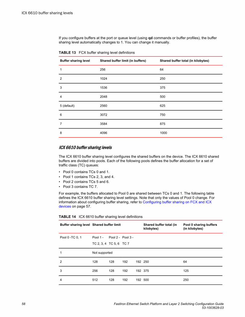
If you configure buffers at the port or queue level (using qd commands or buffer profiles), the buffersharing level automatically changes to 1. You can change it manually.
FCX buffer sharing level definitionsTABLE 13
Buffer sharing level Shared buffer limit (in buffers) Shared buffer total (in kilobytes)
1 256 64
2 1024 250
3 1536 375
4 2048 500
5 (default) 2560 625
6 3072 750
7 3584 875
8 4096 1000
ICX 6610 buffer sharing levels
The ICX 6610 buffer sharing level configures the shared buffers on the device. The ICX 6610 sharedbuffers are divided into pools. Each of the following pools defines the buffer allocation for a set oftraffic class (TC) queues:
• Pool 0 contains TCs 0 and 1.• Pool 1 contains TCs 2, 3, and 4.• Pool 2 contains TCs 5 and 6.• Pool 3 contains TC 7.
For example, the buffers allocated to Pool 0 are shared between TCs 0 and 1. The following tabledefines the ICX 6610 buffer sharing level settings. Note that only the values of Pool 0 change. Forinformation about configuring buffer sharing, refer to Configuring buffer sharing on FCX and ICXdevices on page 57.
ICX 6610 buffer sharing level definitions TABLE 14
Buffer sharing level Shared buffer limit Shared buffer total (inkilobytes)
Pool 0 sharing buffers(in kilobytes)
Pool 0 -TC 0, 1 Pool 1 -
TC 2, 3, 4
Pool 2 -
TC 5, 6
Pool 3 -
TC 7
1 Not supported
2 128 128 192 192 250 64
3 256 128 192 192 375 125
4 512 128 192 192 500 250
ICX 6610 buffer sharing levels
58 FastIron Ethernet Switch Platform and Layer 2 Switching Configuration Guide53-1003628-03
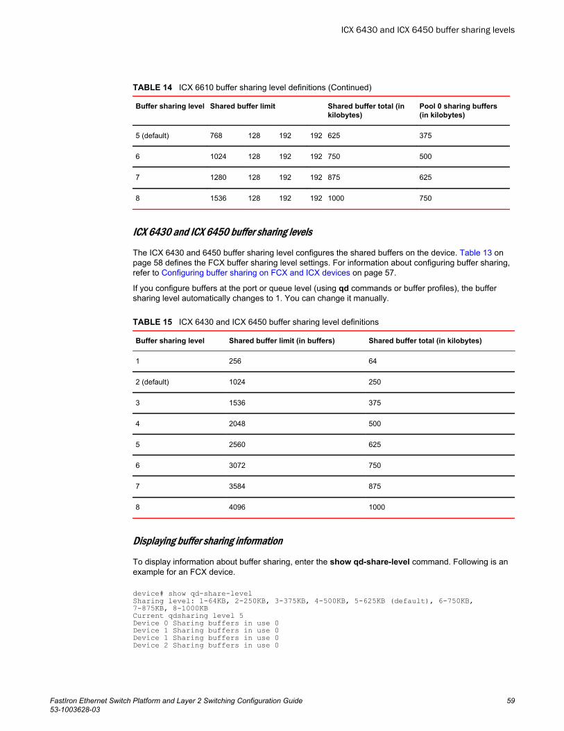
ICX 6610 buffer sharing level definitions (Continued)TABLE 14
Buffer sharing level Shared buffer limit Shared buffer total (inkilobytes)
Pool 0 sharing buffers(in kilobytes)
5 (default) 768 128 192 192 625 375
6 1024 128 192 192 750 500
7 1280 128 192 192 875 625
8 1536 128 192 192 1000 750
ICX 6430 and ICX 6450 buffer sharing levels
The ICX 6430 and 6450 buffer sharing level configures the shared buffers on the device. Table 13 onpage 58 defines the FCX buffer sharing level settings. For information about configuring buffer sharing,refer to Configuring buffer sharing on FCX and ICX devices on page 57.
If you configure buffers at the port or queue level (using qd commands or buffer profiles), the buffersharing level automatically changes to 1. You can change it manually.
ICX 6430 and ICX 6450 buffer sharing level definitionsTABLE 15
Buffer sharing level Shared buffer limit (in buffers) Shared buffer total (in kilobytes)
1 256 64
2 (default) 1024 250
3 1536 375
4 2048 500
5 2560 625
6 3072 750
7 3584 875
8 4096 1000
Displaying buffer sharing information
To display information about buffer sharing, enter the show qd-share-level command. Following is anexample for an FCX device.
device# show qd-share-levelSharing level: 1-64KB, 2-250KB, 3-375KB, 4-500KB, 5-625KB (default), 6-750KB, 7-875KB, 8-1000KBCurrent qdsharing level 5Device 0 Sharing buffers in use 0Device 1 Sharing buffers in use 0Device 1 Sharing buffers in use 0Device 2 Sharing buffers in use 0
ICX 6430 and ICX 6450 buffer sharing levels
FastIron Ethernet Switch Platform and Layer 2 Switching Configuration Guide 5953-1003628-03
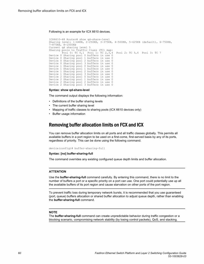
Following is an example for ICX 6610 devices.
ICX6610-48 Router# show qd-share-level Sharing level: 1-64KB, 2-250KB, 3-375KB, 4-500KB, 5-625KB (default), 6-750KB, 7-875KB, 8-1000KB Current qd sharing level 5 Sharing pools to Traffic Class (TC) map: Pool 0: TC 0,1 Pool 1: TC 2,3,4 Pool 2: TC 5,6 Pool 3: TC 7 Device 0 Sharing pool 0 buffers in use 0 Device 0 Sharing pool 1 buffers in use 0 Device 0 Sharing pool 2 buffers in use 0 Device 0 Sharing pool 3 buffers in use 0 Device 1 Sharing pool 0 buffers in use 0 Device 1 Sharing pool 1 buffers in use 0 Device 1 Sharing pool 2 buffers in use 0 Device 1 Sharing pool 3 buffers in use 0 Device 2 Sharing pool 0 buffers in use 0 Device 2 Sharing pool 1 buffers in use 0 Device 2 Sharing pool 2 buffers in use 0 Device 2 Sharing pool 3 buffers in use 0 Syntax: show qd-share-level
The command output displays the following information:
• Definitions of the buffer sharing levels• The current buffer sharing level• Mapping of traffic classes to sharing pools (ICX 6610 devices only)• Buffer usage information
Removing buffer allocation limits on FCX and ICXYou can remove buffer allocation limits on all ports and all traffic classes globally. This permits allavailable buffers in a port region to be used on a first-come, first-served basis by any of its ports,regardless of priority. This can be done using the following command.
device(config)# buffer-sharing-fullSyntax: [no] buffer-sharing-full
The command overrides any existing configured queue depth limits and buffer allocation.
ATTENTION
Use the buffer-sharing-full command carefully. By entering this command, there is no limit to thenumber of buffers a port or a specific priority on a port can use. One port could potentially use up allthe available buffers of its port region and cause starvation on other ports of the port region.
To prevent traffic loss during temporary network bursts, it is recommended that you use guaranteed(port, queue) buffers allocation or shared buffer allocation to adjust queue depth, rather than enablingthe buffer-sharing-full command.
NOTEThe buffer-sharing-full command can create unpredictable behavior during traffic congestion or ablocking scenario, compromising network stability (by losing control packets), QoS, and stacking.
Removing buffer allocation limits on FCX and ICX
60 FastIron Ethernet Switch Platform and Layer 2 Switching Configuration Guide53-1003628-03
Buffer profiles for VoIP on FastIron stackable devices
NOTEConfiguring buffer profiles for VoIP traffic is not supported on FastIron X Series and ICX 6650 devices.Configuring VoIP buffer profiles adds buffer profiles for 1 GbE-to-100 Mbit traffic, simplifyingconfiguration and improving performance.
VoIP profiles allows you to configure a pre-defined set of buffers and descriptors for the priority 0 and 7.These profiles support VoIP traffic that uses priority 7, with 10 Mbps or 100 Mbps uplink ports and 1000Mbps downlink ports.
NOTEIn previous software versions, you could manually configure buffers and descriptors using qdcommands. Buffer profiles for VoIP cannot coexist with qd commands. You may use buffer profiles forVoIP or qd command, but not both at the same time.
Configuring buffer profiles for VoIP
To configure predefined buffers, enter a command similar to the following.
device#buffer-profile port-region 0 voip downlink 100 uplink 1000 Syntax: [no] buffer-profile port-region num voip downlink 100 uplink 1000
NOTEThe port-region num can be either 0 (ports 0/1/1 to 0/1/24) or 1 (ports 0/1/25 to 0/1/48).
NOTEFCX and ICX models (except ICX 6650) do not support this command.
Deleting buffer profiles for VoIP
To delete an existing buffer profile configuration, use the no form of the command.
device#no buffer-profile port-region 0 voip downlink 100 uplink 1000 Syntax: [no] buffer-profile port-region num voip downlink 100 uplink 1000
Buffer allocation for ICX 6650Buffer allocation details for ICX 6650
By default, the architecture allocates fixed buffers on a per-priority queue, per-packet processor basis.The buffers control the total number of packets that can be queued in the outbound transmit for the port.In instances of heavy traffic bursts to aggregation links, such as in stacking configurations or mixed-speed environments, momentary oversubscription of the buffers and descriptors may occur. Adescriptor points to one or more packet buffers.
Buffer profiles for VoIP on FastIron stackable devices
FastIron Ethernet Switch Platform and Layer 2 Switching Configuration Guide 6153-1003628-03
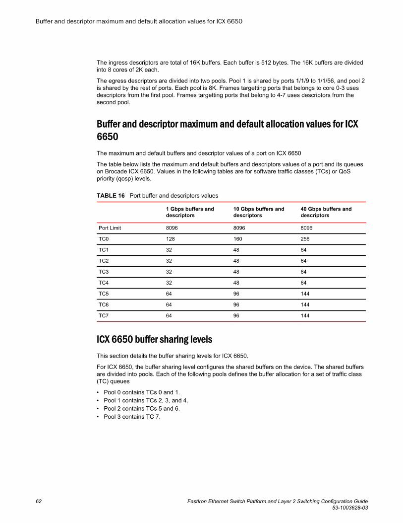
The ingress descriptors are total of 16K buffers. Each buffer is 512 bytes. The 16K buffers are dividedinto 8 cores of 2K each.
The egress descriptors are divided into two pools. Pool 1 is shared by ports 1/1/9 to 1/1/56, and pool 2is shared by the rest of ports. Each pool is 8K. Frames targetting ports that belongs to core 0-3 usesdescriptors from the first pool. Frames targetting ports that belong to 4-7 uses descriptors from thesecond pool.
Buffer and descriptor maximum and default allocation values for ICX6650The maximum and default buffers and descriptor values of a port on ICX 6650
The table below lists the maximum and default buffers and descriptors values of a port and its queueson Brocade ICX 6650. Values in the following tables are for software traffic classes (TCs) or QoSpriority (qosp) levels.
Port buffer and descriptors valuesTABLE 16
1 Gbps buffers anddescriptors
10 Gbps buffers anddescriptors
40 Gbps buffers anddescriptors
Port Limit 8096 8096 8096
TC0 128 160 256
TC1 32 48 64
TC2 32 48 64
TC3 32 48 64
TC4 32 48 64
TC5 64 96 144
TC6 64 96 144
TC7 64 96 144
ICX 6650 buffer sharing levelsThis section details the buffer sharing levels for ICX 6650.
For ICX 6650, the buffer sharing level configures the shared buffers on the device. The shared buffersare divided into pools. Each of the following pools defines the buffer allocation for a set of traffic class(TC) queues
• Pool 0 contains TCs 0 and 1.• Pool 1 contains TCs 2, 3, and 4.• Pool 2 contains TCs 5 and 6.• Pool 3 contains TC 7.
Buffer and descriptor maximum and default allocation values for ICX 6650
62 FastIron Ethernet Switch Platform and Layer 2 Switching Configuration Guide53-1003628-03
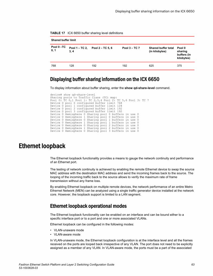
ICX 6650 buffer sharing level definitionsTABLE 17
Shared buffer limit
Pool 0 –TC0, 1
Pool 1 – TC 2,3, 4
Pool 2 – TC 5, 6 Pool 3 – TC 7 Shared buffer total(in kilobytes)
Pool 0sharingbuffers (inkilobytes)
768 128 192 192 625 375
Displaying buffer sharing information on the ICX 6650To display information about buffer sharing, enter the show qd-share-level command.
device# show qd-share-levelSharing pools to Traffic Class (TC) map:Pool 0: TC 0,1 Pool 1: TC 2,3,4 Pool 2: TC 5,6 Pool 3: TC 7Device 0 pool 0 configured buffer limit 768Device 0 pool 1 configured buffer limit 128Device 0 pool 2 configured buffer limit 192Device 0 pool 3 configured buffer limit 192Device 0 Hemisphere 0 Sharing pool 0 buffers in use 0Device 0 Hemisphere 1 Sharing pool 0 buffers in use 0Device 0 Hemisphere 0 Sharing pool 1 buffers in use 0Device 0 Hemisphere 1 Sharing pool 1 buffers in use 0Device 0 Hemisphere 0 Sharing pool 2 buffers in use 0Device 0 Hemisphere 1 Sharing pool 2 buffers in use 0Device 0 Hemisphere 0 Sharing pool 3 buffers in use 0
Ethernet loopbackThe Ethernet loopback functionality provides a means to gauge the network continuity and performanceof an Ethernet port.
The testing of network continuity is achieved by enabling the remote Ethernet device to swap the sourceMAC address with the destination MAC address and send the incoming frames back to the source. Thelooping of the incoming traffic back to the source allows to verify the maximum rate of frametransmission without any frame loss.
By enabling Ethernet loopback on multiple remote devices, the network performance of an entire MetroEthernet Network (MEN) can be analyzed using a single traffic generator device installed at the networkcore. However, the loopback support is limited to a LAN segment.
Ethernet loopback operational modesThe Ethernet loopback functionality can be enabled on an interface and can be bound either to aspecific interface port or to a port and one or more associated VLANs.
Ethernet loopback can be configured in the following modes:
• VLAN-unaware mode• VLAN-aware mode
In VLAN-unaware mode, the Ethernet loopback configuration is at the interface level and all the framesreceived on the ports are looped back irrespective of any VLAN. The port does not need to be explicitlyassigned as a member of any VLAN. In VLAN-aware mode, the ports must be a part of the associated
Displaying buffer sharing information on the ICX 6650
FastIron Ethernet Switch Platform and Layer 2 Switching Configuration Guide 6353-1003628-03
VLAN and all the frames received on the ports that are associated with a specific VLAN are loopedback. The VLANs to which the port is not associated with the loopback function will continue toprocess traffic normally, allowing non-disruptive loopback testing.
A classification of the traffic flow can also be configured in VLAN-aware and VLAN-unaware modes.The loopback can be configured as flow-aware by specifying the source MAC address and destinationMAC address on the interface. In the flow-aware configuration, only the frames received with a specificsource MAC address and destination MAC address are looped back. During the loopback, the sourceMAC address and destination MAC address of the packets are swapped.
Ethernet loopback-enabled ports can send the incoming frames back to the source in the flow-unaware mode also. If the source MAC address and destination MAC address are not specified, all theframes received on the port are looped back and the port does not distinguish between control anddata traffic and Ethernet address types (unicast, multicast, or broadcast). This makes the flow-unaware mode disruptive because control traffic is also looped back and affects other servicesoperating on this port. However, this mode is effective when the traffic source device is directlyconnected to the port .
Ethernet loopback can be configured in the following combinations:
• VLAN-unaware and flow-unaware• VLAN-unaware and flow-aware• VLAN-aware and flow-unaware• VLAN-aware and flow-aware
NOTEThe flow-unaware configuration is not supported on the Brocade ICX 7750, Brocade ICX 7450, andBrocade ICX 7250.
Ethernet loopback configuration considerationsThe configuration considerations for Ethernet loopback are as follows:
• An interface port cannot be configured in both flow-aware and flow-unaware modes simultaneously.• An interface port cannot be configured in both VLAN-aware and VLAN-unaware modes
simultaneously.• The source MAC address and destination MAC address which define the flow-aware configuration
must be unicast MAC addresses.• The source MAC address configured in the flow-aware configuration must be unique across the
network.• Ports can be added or removed in different Ethernet loopback modes.• A flow-aware configuration can be added on an in-service Ethernet loopback port.• A flow-aware configuration on a port cannot be removed from an in-service Ethernet loopback port.• The Ethernet loopback configuration is persistent across reboots if the configuration is saved. This
will help to measure switching time at reload time from a remote device.• Ethernet loopback cannot be enabled when one or more of the following features are configured:
‐ ACL‐ 802.1X port security‐ Traffic shaping‐ Dual mode‐ Rate limiting
Ethernet loopback configuration considerations
64 FastIron Ethernet Switch Platform and Layer 2 Switching Configuration Guide53-1003628-03

• Ethernet loopback depends on ACL entry availability because it uses ACL resources.• MAC learning is not supported for a packet that is looped back in devices other than the Brocade ICX
7750, Brocade ICX 7450, and Brocade ICX 7250.• Static MAC configuration is not allowed globally when Ethernet loopback is configured in the system.• When Ethernet loopback is enabled, the packets are looped back at the rate received. However, the
packets can be dropped potentially when the device is oversubscribed.• Ethernet loopback is supported on the physical interface and LAG interface.• Ethernet loopback can be enabled only on an existing LAG.• An Ethernet loopback-enabled LAG cannot be undeployed.• An Ethernet loopback-enabled port cannot be added to an existing LAG.• VLAN priority remarking is not allowed on an Ethernet loopback-enabled port.• The state of the port (up or down) does not affect the Ethernet loopback functionality.• Ethernet loopback configuration is not allowed on mult-range VLAN (MVLAN), VLAN Group, or VLAN
Range.• Ethernet loopback cannot be configured on a set of VLANs that share a Layer 2 topology (Topology
Group).• Ethernet loopback must be configured in a loop-free network for better results.• Configuring Ethernet loopback on an MCT ICL port is not recommended as it may impact MCT
operations.
Configuring Ethernet loopback in VLAN-unaware modeThe following steps configure Ethernet loopback in VLAN-unaware mode.
1. Enter the configure terminal command to enter global configuration mode.device# configure terminal
2. Enter the interface ethernet command to enter interface configuration mode. device(config)# interface ethernet 1/1/1
3. (Optional) Enter the ethernet loopback test-mac command to configure the port as flow-aware.Once configured and when Ethernet loopback is enabled, only the frames received with the specificsource MAC address and destination MAC address are looped back. Skip this step to configure flow-unaware mode.
NOTEOn Brocade ICX 7750, Brocade ICX 7450, and Brocade ICX 7250 devices, configuring the ethernetloopback test-mac command is mandatory because these devices support only flow-aware mode.
device(config-if-e1000-1/1/1)# ethernet loopback test-mac 1111.2222.3333 4444.5555.5555
4. Enter the ethernet loopback command to enable Ethernet loopback.device(config-if-e1000-1/1/1)# ethernet loopback
The following example configures Ethernet loopback in VLAN-unaware mode as flow-aware.device# configure terminaldevice(config)# interface ethernet 1/1/1device(config-if-e1000-1/1/1)# ethernet loopback test-mac 1111.2222.3333 4444.5555.5555device(config-if-e1000-1/1/1)# ethernet loopback
The following example configures Ethernet loopback in VLAN-unaware mode as flow-unaware.device# configure terminaldevice(config)# interface ethernet 1/1/1device(config-if-e1000-1/1/1)# ethernet loopback
Configuring Ethernet loopback in VLAN-unaware mode
FastIron Ethernet Switch Platform and Layer 2 Switching Configuration Guide 6553-1003628-03
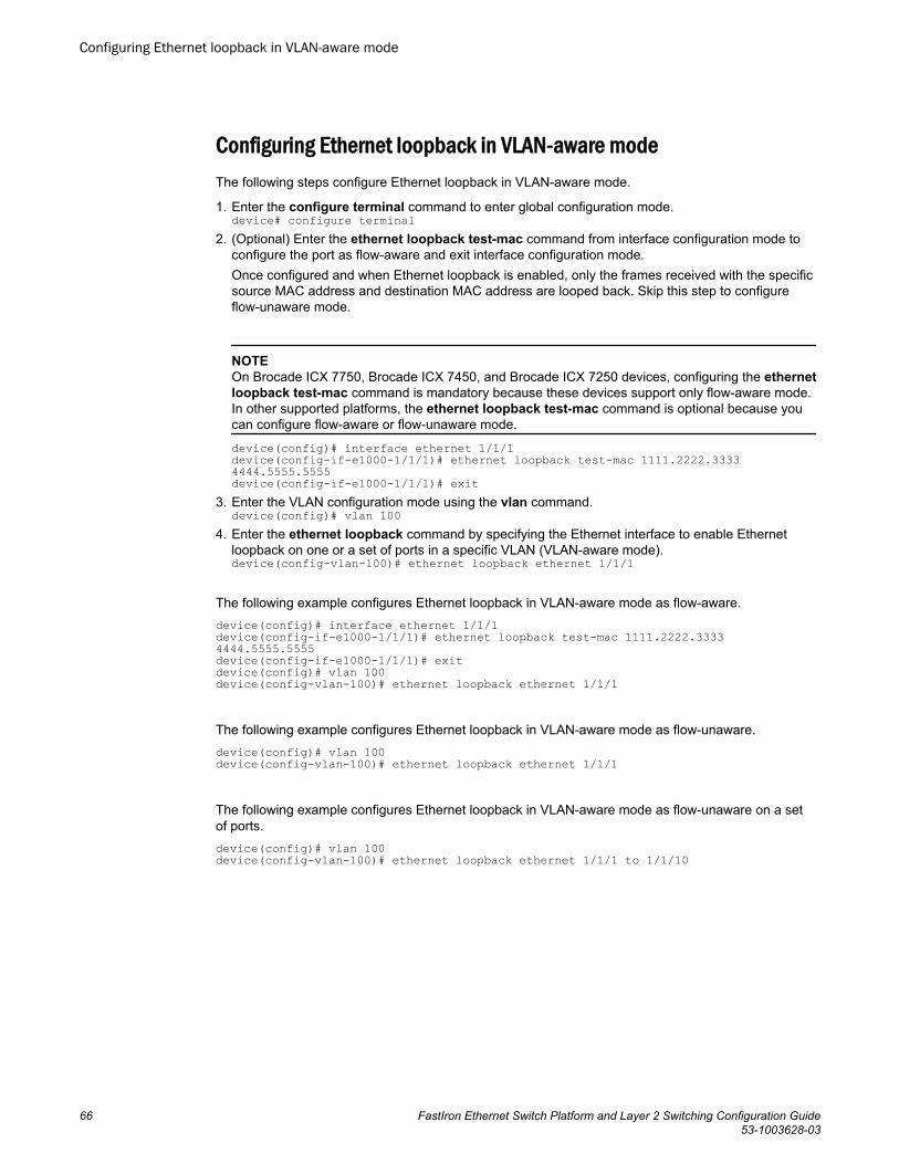
Configuring Ethernet loopback in VLAN-aware modeThe following steps configure Ethernet loopback in VLAN-aware mode.
1. Enter the configure terminal command to enter global configuration mode.device# configure terminal
2. (Optional) Enter the ethernet loopback test-mac command from interface configuration mode toconfigure the port as flow-aware and exit interface configuration mode.Once configured and when Ethernet loopback is enabled, only the frames received with the specificsource MAC address and destination MAC address are looped back. Skip this step to configureflow-unaware mode.
NOTEOn Brocade ICX 7750, Brocade ICX 7450, and Brocade ICX 7250 devices, configuring the ethernetloopback test-mac command is mandatory because these devices support only flow-aware mode.In other supported platforms, the ethernet loopback test-mac command is optional because youcan configure flow-aware or flow-unaware mode.
device(config)# interface ethernet 1/1/1 device(config-if-e1000-1/1/1)# ethernet loopback test-mac 1111.2222.3333 4444.5555.5555device(config-if-e1000-1/1/1)# exit
3. Enter the VLAN configuration mode using the vlan command.device(config)# vlan 100
4. Enter the ethernet loopback command by specifying the Ethernet interface to enable Ethernetloopback on one or a set of ports in a specific VLAN (VLAN-aware mode).device(config-vlan-100)# ethernet loopback ethernet 1/1/1
The following example configures Ethernet loopback in VLAN-aware mode as flow-aware.device(config)# interface ethernet 1/1/1device(config-if-e1000-1/1/1)# ethernet loopback test-mac 1111.2222.3333 4444.5555.5555device(config-if-e1000-1/1/1)# exitdevice(config)# vlan 100device(config-vlan-100)# ethernet loopback ethernet 1/1/1
The following example configures Ethernet loopback in VLAN-aware mode as flow-unaware.device(config)# vlan 100device(config-vlan-100)# ethernet loopback ethernet 1/1/1
The following example configures Ethernet loopback in VLAN-aware mode as flow-unaware on a setof ports.device(config)# vlan 100device(config-vlan-100)# ethernet loopback ethernet 1/1/1 to 1/1/10
Configuring Ethernet loopback in VLAN-aware mode
66 FastIron Ethernet Switch Platform and Layer 2 Switching Configuration Guide53-1003628-03
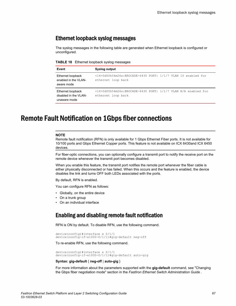
Ethernet loopback syslog messagesThe syslog messages in the following table are generated when Ethernet loopback is configured orunconfigured.
Ethernet loopback syslog messagesTABLE 18
Event Syslog output
Ethernet loopbackenabled in the VLAN-aware mode
<14>0d00h56m26s:BROCADE-6430 PORT: 1/1/7 VLAN 10 enabled forethernet loop back
Ethernet loopbackdisabled in the VLAN-unaware mode
<14>0d00h56m26s:BROCADE-6430 PORT: 1/1/7 VLAN N/A enabled forethernet loop back
Remote Fault Notification on 1Gbps fiber connections
NOTERemote fault notification (RFN) is only available for 1 Gbps Ethernet Fiber ports. It is not available for10/100 ports and Gbps Ethernet Copper ports. This feature is not available on ICX 6430and ICX 6450devices.
For fiber-optic connections, you can optionally configure a transmit port to notify the receive port on theremote device whenever the transmit port becomes disabled.
When you enable this feature, the transmit port notifies the remote port whenever the fiber cable iseither physically disconnected or has failed. When this occurs and the feature is enabled, the devicedisables the link and turns OFF both LEDs associated with the ports.
By default, RFN is enabled.
You can configure RFN as follows:
• Globally, on the entire device• On a trunk group• On an individual interface
Enabling and disabling remote fault notificationRFN is ON by default. To disable RFN, use the following command.
device(config)#interface e 0/1/1device(config-if-e1000-0/1/1)#gig-default neg-offTo re-enable RFN, use the following command.
device(config)#interface e 0/1/1device(config-if-e1000-0/1/1)#gig-default auto-gigSyntax: gig-default { neg-off | auto-gig }
For more information about the parameters supported with the gig-default command, see "Changingthe Gbps fiber negotiation mode" section in the FastIron Ethernet Switch Administration Guide .
Ethernet loopback syslog messages
FastIron Ethernet Switch Platform and Layer 2 Switching Configuration Guide 6753-1003628-03
Link Fault Signaling for 10Gbps Ethernet devicesLink Fault Signaling (LFS) is a physical layer protocol that enables communication on a link betweentwo 10 Gbps Ethernet devices. When configured on a Brocade 10 Gbps Ethernet port, the port candetect and report fault conditions on transmit and receive ports.
When LFS is enabled on an interface, the following Syslog messages are generated when the linkgoes up or down, or when the TX or RX fiber is removed from one or both sides of the link that hasLFS enabled.
Interface ethernet 1/1/1, state down - link downInterface ethernet 1/1/1, state upWhen a link fault occurs, the Link and Activity LEDs turn OFF.
The Link and Activity LEDs turn ON when there is traffic traversing the link after the fiber is installed.
On Brocade FastIron devices, RX LFS is always enabled by default and cannot be disabled. The [no]link-fault-signal command only applies to enabling or disabling TX LFS.
Enabling Link Fault SignalingTo enable Link Fault Signaling (LFS) between two 10 Gbps Ethernet devices, enter commands suchas the following on both ends of the link.
device(config)#interface e 1/1/1device(config-if-e1000-1/1/1)#link-fault-signalSyntax: [no] link-fault-signal
Use the no form of the command to disable LFS.
Viewing the status of LFS-enabled linksThe status of an LFS-enabled link is shown in the output of the show interface and show interfacebrief commands, as shown in the following examples.
device#show interface e 1/1/1010GigabitEthernet1/1/10 is down (remote fault), line protocol is down Hardware is 10GigabitEthernet, address is 0000.0027.79d8 (bia 0000.0027.79d8) Configured speed 10Gbit, actual unknown, configured duplex fdx, actual unknown Member of L2 VLAN ID 1, port is untagged, port state is BLOCKING BPDU guard is Disabled, ROOT protect is Disabled Link Fault Signaling is Enabled, Link Error Dampening is Disabled STP configured to ON, priority is level0 Flow Control is disabled mirror disabled, monitor disabledTruncated for brevity...
The bold text in the above output shows that the LFS-enabled link (port 1/1/10) is down because of anerror on the remote port, as indicated by remote fault .
Syntax: show interface ethernet port
device#show interfaces briefPort Link State Dupl Speed Trunk Tag Pvid Pri MAC Name1/1/10 Err-LFS None None None None No 1 0 0000.0027.79d8The bold text in the above output indicates that there is an error on the LFS-enabled link on port 1/1/10and the link is down.
Link Fault Signaling for 10Gbps Ethernet devices
68 FastIron Ethernet Switch Platform and Layer 2 Switching Configuration Guide53-1003628-03
Syntax: show interfaces brief
Jumbo frame supportEthernet traffic moves in units called frames. The maximum size of frames is called the MaximumTransmission Unit (MTU). When a network device receives a frame larger than its MTU, the data iseither fragmented or dropped. Historically, Ethernet has a maximum frame size of 1500 bytes, so mostdevices use 1500 as their default MTU.
Jumbo frames are Ethernet frames with more than 1,500 bytes MTU. Conventionally, jumbo frames cancarry up to 10200 bytes MTU. Brocade FastIron devices support Layer 2 jumbo frames on 10/100,100/100/1000, and 10GbE ports.
Brocade ICX 6650 devices support Layer 2 jumbo frames on 10/100, 100/100/1000, 40GbE and 10GbEports. Conventionally, jumbo frames can carry up to 9,000 bytes MTU. In cut-through mode, in jumbomode, the MTU is 10200 which uses 20 buffers. In non-jumbo mode MTU is 1522 which uses 3 buffers.
Packet InError Detection
Packet InError Detection identifies links that receive more number of bad frames than configuredthreshold and disables them to avoid instability in the network. For instance, if a network has redundantuplinks, usually only one link is in forwarding state and the rest are redundant and blocked. If one of theredundant links becomes faulty, it may drop the PDUs and become a forwarding link. This can causeloops in the network. Packet InError Detection detects the faults in the link and disables the link toprevent loops in the network.
Packet InError Detection counts an ingress frame that has one or more of the following errors as aninError packet:
• Alignment error• CRC error• Oversized frame error• Internal received MAC address error (Errors that do not fall in the above 3 types)• Symbol error (includes the fragmented, short, or undersized frames)
You can configure the number of inError packets allowed per port in a specified sampling interval. If theport receives more than the configured number of inError packets in two consecutive sampling intervals,then the port becomes error-disabled. The output of the show interface ethernet command for theaffected port will show the status of the port as “ERR-DISABLED (packet-inerror)”.
NOTEIt is recommended to use Packet InError Detection only on required ports. If you enable this on a largenumber of ports in a device and use a very short sampling interval, it may lead to heavy CPU usage.
NOTEThe inError count configured on the primary port of a LAG is inherited by other member ports of theLAG. However, the LAG ports are individually sampled for inError packets. Therefore, inError packetson a port disable only that port and not the entire LAG.
Jumbo frame support
FastIron Ethernet Switch Platform and Layer 2 Switching Configuration Guide 6953-1003628-03
NOTEExecuting commands that clear the packet counters, such as the clear statistics command mayinterfere with the proper functioning of Packet InError Detection because these commands reset theinError packet count.
Configuring Packet InError Detection
Perform the following steps to configure Packet InError Detection:
1. Run the errdisable packet-inerror-detect command in global configuration mode to enable thefeature and to define the sampling time interval.
2. Run the packet-inerror-detect command in interface configuration mode of the port that you wantto monitor for inError packets.
3. (Optional) If you want the ports to automatically recover from the error-disabled state after theexpiry of a configured recovery timer, run the errdisable recovery cause and errdisable recoveryinterval commands in global configuration mode. For more details, see “Enabling an error-disabledport automatically” on page 15 on page 323 and Setting the recovery interval on page 324.
The following example shows the configuration of Packet InError Detection on a device and itsEthernet interface 1/1/1.Brocade(config)# errdisable packet-inerror-detect interval 3Brocade(config)# errdisable recovery cause packet-inerror-detectBrocade(config)# errdisable recovery interval 20Brocade(config)# interface ethernet 1/1/1Brocade(config-if-e1000-1/1/1)# packet-inerror-detect 10The ethernet interface 1/1/1 becomes disabled if more than 10 inError packets are received in each oftwo consecutive 3-second intervals. After the interface is disabled, it automatically recovers to theenabled state after 20 seconds.
Syslog message for error-disabled port due to inError packets
The following syslog message is generated when a port is error-disabled because of inError packets.0d01h38m44s:I:PORT: 1/1/37 is ERR-DISABLED due to number of packet inErrors exceeded the threshold
Configuring Packet InError Detection
70 FastIron Ethernet Switch Platform and Layer 2 Switching Configuration Guide53-1003628-03
Metro Features
● Topology groups............................................................................................................. 71● Metro Ring Protocol ....................................................................................................... 74● VSRP.............................................................................................................................. 95
Topology groupsA topology group is a named set of VLANs that share a Layer 2 topology. Topology groups simplifyconfiguration and enhance scalability of Layer 2 protocols by allowing you to run a single instance of aLayer 2 protocol on multiple VLANs.
You can use topology groups with the following Layer 2 protocols:
• STP/RSTP• MRP• VSRP• 802.1W
Topology groups simplify Layer 2 configuration and provide scalability by enabling you to use the sameinstance of a Layer 2 protocol for multiple VLANs. For example, if a Brocade device is deployed in aMetro network and provides forwarding for two MRP rings that each contain 128 VLANs, you canconfigure a topology group for each ring. If a link failure in a ring causes a topology change, the changeis applied to all the VLANs in the ring topology group. Without topology groups, you would need toconfigure a separate ring for each VLAN.
Master VLAN and member VLANsEach topology group contains a master VLAN and can contain one or more member VLANs and VLANgroups:
• Master VLAN - The master VLAN contains the configuration information for the Layer 2 protocol. Forexample, if you plan to use the topology group for MRP, the topology group master VLAN containsthe ring configuration information.
• Member VLANs - The member VLANs are additional VLANs that share ports with the master VLAN.The Layer 2 protocol settings for the ports in the master VLAN apply to the same ports in the memberVLANs. A change to the master VLAN Layer 2 protocol configuration or Layer 2 topology affects allthe member VLANs. Member VLANs do not independently run a Layer 2 protocol.
• Member VLAN groups - A VLAN group is a named set of VLANs. The VLANs within a VLAN grouphave the same ports and use the same values for other VLAN parameters.
When a Layer 2 topology change occurs on a port in the master VLAN, the same change is applied tothat port in all the member VLANs that contain the port. For example, if you configure a topology groupwhose master VLAN contains ports 1/1/1 and 1/1/2, a Layer 2 state change on port 1/1/1 applies to port1/1/1 in all the member VLANs that contain that port. However, the state change does not affect port1/1/1 in VLANs that are not members of the topology group.
FastIron Ethernet Switch Platform and Layer 2 Switching Configuration Guide 7153-1003628-03
Control ports and free portsA port that is in a topology group can be a control port or a free port:
• Control port - A control port is a port in the master VLAN, and is therefore controlled by the Layer 2protocol configured in the master VLAN. The same port in all the member VLANs is controlled bythe master VLAN Layer 2 protocol. Each member VLAN must contain all of the control ports andcan contain additional ports.
• Free port - A free port is not controlled by the master VLAN Layer 2 protocol. The master VLAN cancontain free ports. (In this case, the Layer 2 protocol is disabled on those ports.) In addition, anyports in the member VLANs that are not also in the master VLAN are free ports.
NOTESince free ports are not controlled by the master port Layer 2 protocol, they are assumed to always bein the Forwarding state.
Topology group configuration considerations• You must configure the master VLAN and member VLANs or member VLAN groups before you
configure the topology group.• You can configure up to 30 (256 for ICX 6650) topology groups. Each group can control up to 4096
VLANs. A VLAN cannot be controlled by more than one topology group.• The topology group must contain a master VLAN and can also contain individual member VLANs,
VLAN groups, or a combination of individual member VLANs and VLAN groups.• If you add a new master VLAN to a topology group that already has a master VLAN, the new
master VLAN replaces the older master VLAN. All member VLANs and VLAN groups follow theLayer 2 protocol settings of the new master VLAN.
• If you remove the master VLAN (by entering no master-vlan vlan-id ), the software selects the newmaster VLAN from member VLANs. A new candidate master VLAN will be in configured order to amember VLAN so that the first added member VLAN will be a new candidate master VLAN. Onceyou save and reload, a member-vlan with the youngest VLAN ID will be the new candidate master.The new master VLAN inherits the Layer 2 protocol settings of the older master VLAN.
• The topology group will be deleted if the master is deleted and there are no member VLANs. This istrue even if the topology group has member-groups.
• Once you add a VLAN as a member of a topology group, all the Layer 2 protocol information on theVLAN is deleted.
• A default VLAN cannot be a member of a topology group.
Configuring a topology groupTo configure a topology group, enter commands such as the following.
device(config)#topology-group 2device(config-topo-group-2)#master-vlan 2device(config-topo-group-2)#member-vlan 3device(config-topo-group-2)#member-vlan 4device(config-topo-group-2)#member-vlan 5device(config-topo-group-2)#member-group 2These commands create topology group 2 and add the following:
• Master VLAN 2• Member VLANs 2, 3, and 4• Member VLAN group 2
Control ports and free ports
72 FastIron Ethernet Switch Platform and Layer 2 Switching Configuration Guide53-1003628-03
Syntax: [no] topology-group group-id
The group-id parameter specifies the topology group ID and can be from 1 - 256.
Syntax: [no] master-vlan vlan-id
This command adds the master VLAN. The VLAN must already be configured. Make sure all the Layer2 protocol settings in the VLAN are correct for your configuration before you add the VLAN to thetopology group. A topology group can have only one master VLAN.
NOTEWhen removing the master VLAN from the topology group, spanning tree is disabled on the masterVLAN.
NOTEIf you remove the master VLAN (by entering no master-vlan vlan-id ), the software selects the newmaster VLAN from member VLANs. For example, if you remove master VLAN 2 from the exampleabove, the CLI converts member VLAN 3 into the new master VLAN. The new master VLAN inherits theLayer 2 protocol settings of the older master VLAN.
NOTEIf you add a new master VLAN to a topology group that already has a master VLAN, the new masterVLAN replaces the older master VLAN. All member VLANs and VLAN groups follow the Layer 2protocol settings of the new master VLAN.
Syntax: [no] member-vlan vlan-id
The vlan-id parameter specifies a VLAN ID. The VLAN must already be configured.
Syntax: [no] member-group num
The num specifies a VLAN group ID. The VLAN group must already be configured.
NOTEOnce you add a VLAN or VLAN group as a member of a topology group, all the Layer 2 protocolconfiguration information for the VLAN or group is deleted. For example, if STP is configured on a VLANand you add the VLAN to a topology group, the STP configuration is removed from the VLAN. Once youadd the VLAN to a topology group, the VLAN uses the Layer 2 protocol settings of the master VLAN. Ifyou remove a member VLAN or VLAN group from a topology group, you will need to reconfigure theLayer 2 protocol information in the VLAN or VLAN group.
Displaying topology group informationThe following sections show how to display STP information and topology group information for VLANS.
Displaying STP information
To display STP information for a VLAN, enter a command such as the following.
device#show span vlan 4VLAN 4 BPDU cam_index is 14344 and the Master DMA Are(HEX) 18 1A STP instance owned by VLAN 2
Displaying topology group information
FastIron Ethernet Switch Platform and Layer 2 Switching Configuration Guide 7353-1003628-03
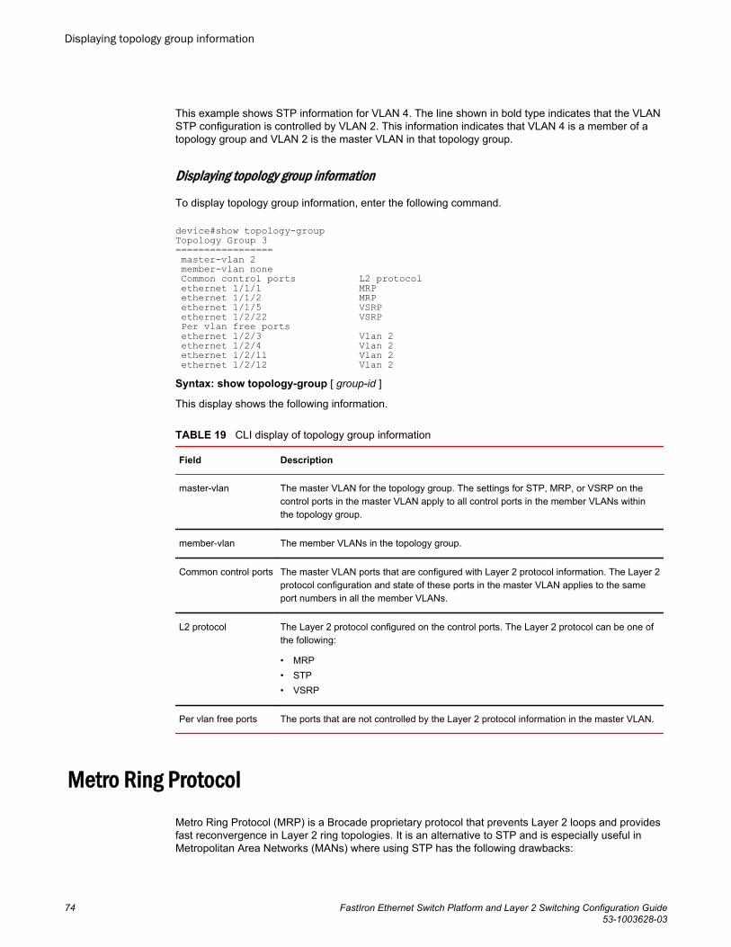
This example shows STP information for VLAN 4. The line shown in bold type indicates that the VLANSTP configuration is controlled by VLAN 2. This information indicates that VLAN 4 is a member of atopology group and VLAN 2 is the master VLAN in that topology group.
Displaying topology group information
To display topology group information, enter the following command.
device#show topology-groupTopology Group 3================= master-vlan 2 member-vlan none Common control ports L2 protocol ethernet 1/1/1 MRP ethernet 1/1/2 MRP ethernet 1/1/5 VSRP ethernet 1/2/22 VSRP Per vlan free ports ethernet 1/2/3 Vlan 2 ethernet 1/2/4 Vlan 2 ethernet 1/2/11 Vlan 2 ethernet 1/2/12 Vlan 2Syntax: show topology-group [ group-id ]
This display shows the following information.
CLI display of topology group information TABLE 19
Field Description
master-vlan The master VLAN for the topology group. The settings for STP, MRP, or VSRP on thecontrol ports in the master VLAN apply to all control ports in the member VLANs withinthe topology group.
member-vlan The member VLANs in the topology group.
Common control ports The master VLAN ports that are configured with Layer 2 protocol information. The Layer 2protocol configuration and state of these ports in the master VLAN applies to the sameport numbers in all the member VLANs.
L2 protocol The Layer 2 protocol configured on the control ports. The Layer 2 protocol can be one ofthe following:
• MRP• STP• VSRP
Per vlan free ports The ports that are not controlled by the Layer 2 protocol information in the master VLAN.
Metro Ring ProtocolMetro Ring Protocol (MRP) is a Brocade proprietary protocol that prevents Layer 2 loops and providesfast reconvergence in Layer 2 ring topologies. It is an alternative to STP and is especially useful inMetropolitan Area Networks (MANs) where using STP has the following drawbacks:
Displaying topology group information
74 FastIron Ethernet Switch Platform and Layer 2 Switching Configuration Guide53-1003628-03
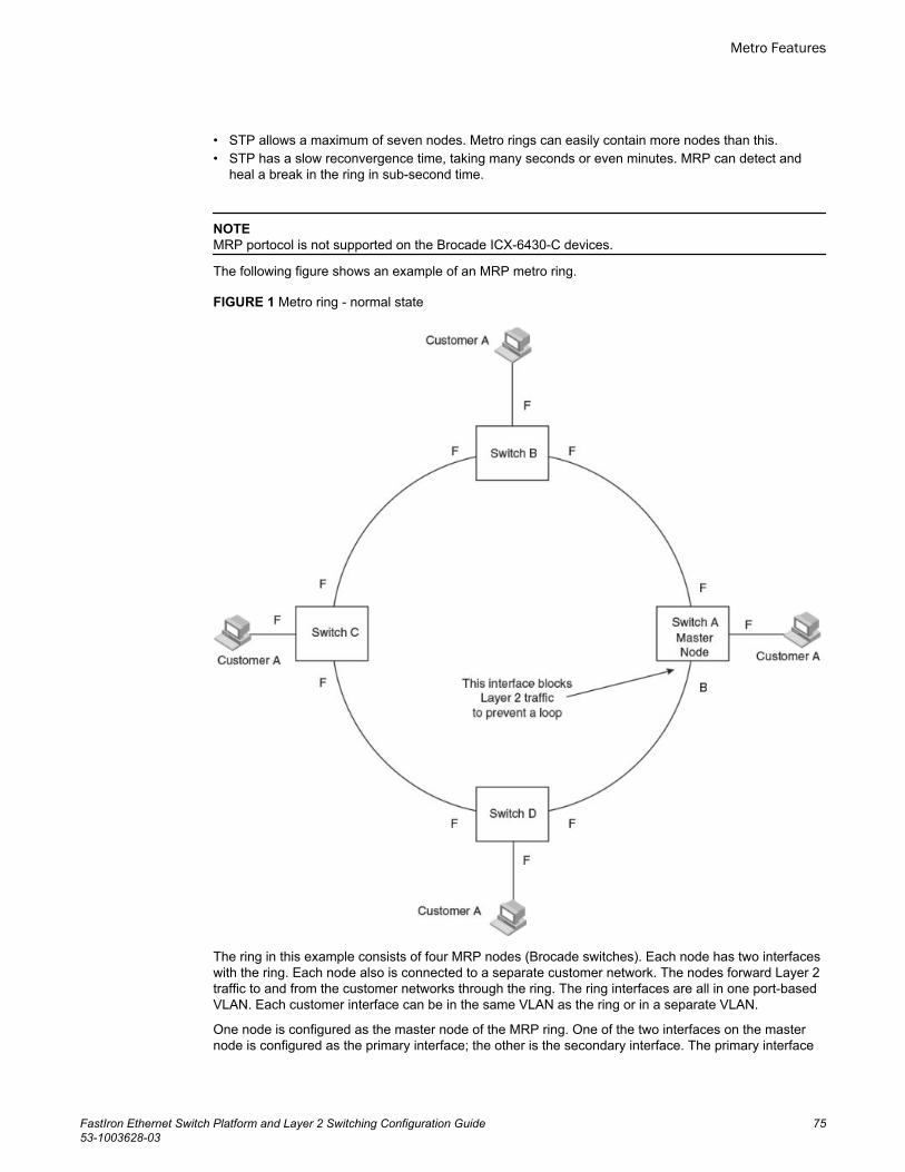
• STP allows a maximum of seven nodes. Metro rings can easily contain more nodes than this.• STP has a slow reconvergence time, taking many seconds or even minutes. MRP can detect and
heal a break in the ring in sub-second time.
NOTEMRP portocol is not supported on the Brocade ICX-6430-C devices.
The following figure shows an example of an MRP metro ring.
FIGURE 1 Metro ring - normal state
The ring in this example consists of four MRP nodes (Brocade switches). Each node has two interfaceswith the ring. Each node also is connected to a separate customer network. The nodes forward Layer 2traffic to and from the customer networks through the ring. The ring interfaces are all in one port-basedVLAN. Each customer interface can be in the same VLAN as the ring or in a separate VLAN.
One node is configured as the master node of the MRP ring. One of the two interfaces on the masternode is configured as the primary interface; the other is the secondary interface. The primary interface
Metro Features
FastIron Ethernet Switch Platform and Layer 2 Switching Configuration Guide 7553-1003628-03
originates Ring Health Packets (RHPs), which are used to monitor the health of the ring. An RHP isforwarded on the ring to the next interface until it reaches the secondary interface of the master node.The secondary interface blocks the packet to prevent a Layer 2 loops.
Metro Ring Protocol configuration notes• When you configure Metro Ring Protocol (MRP), Brocade recommends that you disable one of the
ring interfaces before beginning the ring configuration. Disabling an interface prevents a Layer 2loop from occurring while you are configuring MRP on the ring nodes. Once MRP is configured andenabled on all the nodes, you can re-enable the interface.
• The above configurations can be configured as MRP masters or MRP members (for different rings).• Brocade does not recommend configuring more than 15 MRP instances on FCX and ICX 6650
devices. Also, due to hardware limitations on this platforms, configuring 40 or more MRP instancesmay cause errors.
• If you configure MRP on a device running Layer 3 software, then restart the device running Layer 2software, the MRP configuration gets deleted.
MRP rings without shared interfaces (MRP Phase 1)MRP Phase 1 allows you to configure multiple MRP rings, as shown in Figure 2 , but the rings cannotshare the same link. For example, you cannot configure ring 1 and ring 2 to each have interfaces 1/1/1and 1/1/2.
Also, when you configure an MRP ring, any node on the ring can be designated as the master nodefor the ring. A master node can be the master node of more than one ring. (Refer to Figure 2 .) Eachring is an independent ring and RHP packets are processed within each ring.
Metro Ring Protocol configuration notes
76 FastIron Ethernet Switch Platform and Layer 2 Switching Configuration Guide53-1003628-03
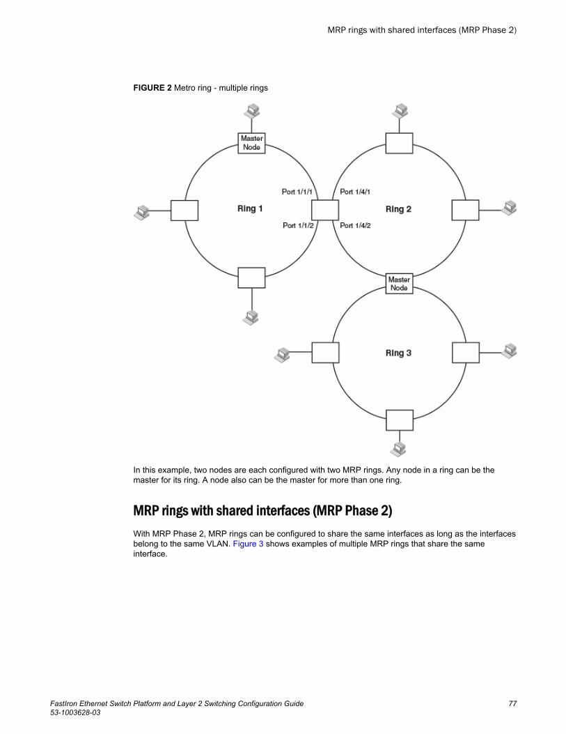
FIGURE 2 Metro ring - multiple rings
In this example, two nodes are each configured with two MRP rings. Any node in a ring can be themaster for its ring. A node also can be the master for more than one ring.
MRP rings with shared interfaces (MRP Phase 2)With MRP Phase 2, MRP rings can be configured to share the same interfaces as long as the interfacesbelong to the same VLAN. Figure 3 shows examples of multiple MRP rings that share the sameinterface.
MRP rings with shared interfaces (MRP Phase 2)
FastIron Ethernet Switch Platform and Layer 2 Switching Configuration Guide 7753-1003628-03
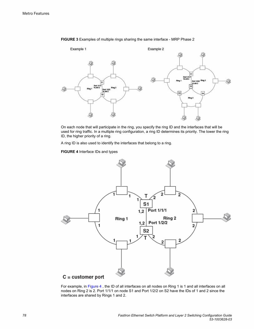
FIGURE 3 Examples of multiple rings sharing the same interface - MRP Phase 2
On each node that will participate in the ring, you specify the ring ID and the interfaces that will beused for ring traffic. In a multiple ring configuration, a ring ID determines its priority. The lower the ringID, the higher priority of a ring.
A ring ID is also used to identify the interfaces that belong to a ring.
FIGURE 4 Interface IDs and types
For example, in Figure 4 , the ID of all interfaces on all nodes on Ring 1 is 1 and all interfaces on allnodes on Ring 2 is 2. Port 1/1/1 on node S1 and Port 1/2/2 on S2 have the IDs of 1 and 2 since theinterfaces are shared by Rings 1 and 2.
Metro Features
78 FastIron Ethernet Switch Platform and Layer 2 Switching Configuration Guide53-1003628-03
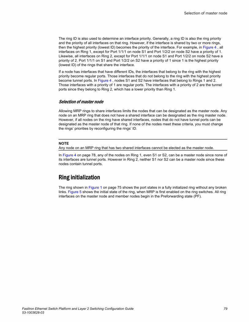
The ring ID is also used to determine an interface priority. Generally, a ring ID is also the ring priorityand the priority of all interfaces on that ring. However, if the interface is shared by two or more rings,then the highest priority (lowest ID) becomes the priority of the interface. For example, in Figure 4 , allinterfaces on Ring 1, except for Port 1/1/1 on node S1 and Port 1/2/2 on node S2 have a priority of 1.Likewise, all interfaces on Ring 2, except for Port 1/1/1 on node S1 and Port 1/2/2 on node S2 have apriority of 2. Port 1/1/1 on S1 and Port 1/2/2 on S2 have a priority of 1 since 1 is the highest priority(lowest ID) of the rings that share the interface.
If a node has interfaces that have different IDs, the interfaces that belong to the ring with the highestpriority become regular ports. Those interfaces that do not belong to the ring with the highest prioritybecome tunnel ports. In Figure 4 , nodes S1 and S2 have interfaces that belong to Rings 1 and 2.Those interfaces with a priority of 1 are regular ports. The interfaces with a priority of 2 are the tunnelports since they belong to Ring 2, which has a lower priority than Ring 1.
Selection of master node
Allowing MRP rings to share interfaces limits the nodes that can be designated as the master node. Anynode on an MRP ring that does not have a shared interface can be designated as the ring master node.However, if all nodes on the ring have shared interfaces, nodes that do not have tunnel ports can bedesignated as the master node of that ring. If none of the nodes meet these criteria, you must changethe rings’ priorities by reconfiguring the rings’ ID.
NOTEAny node on an MRP ring that has two shared interfaces cannot be elected as the master node.
In Figure 4 on page 78, any of the nodes on Ring 1, even S1 or S2, can be a master node since none ofits interfaces are tunnel ports. However in Ring 2, neither S1 nor S2 can be a master node since thesenodes contain tunnel ports.
Ring initializationThe ring shown in Figure 1 on page 75 shows the port states in a fully initialized ring without any brokenlinks. Figure 5 shows the initial state of the ring, when MRP is first enabled on the ring switches. All ringinterfaces on the master node and member nodes begin in the Preforwarding state (PF).
Selection of master node
FastIron Ethernet Switch Platform and Layer 2 Switching Configuration Guide 7953-1003628-03
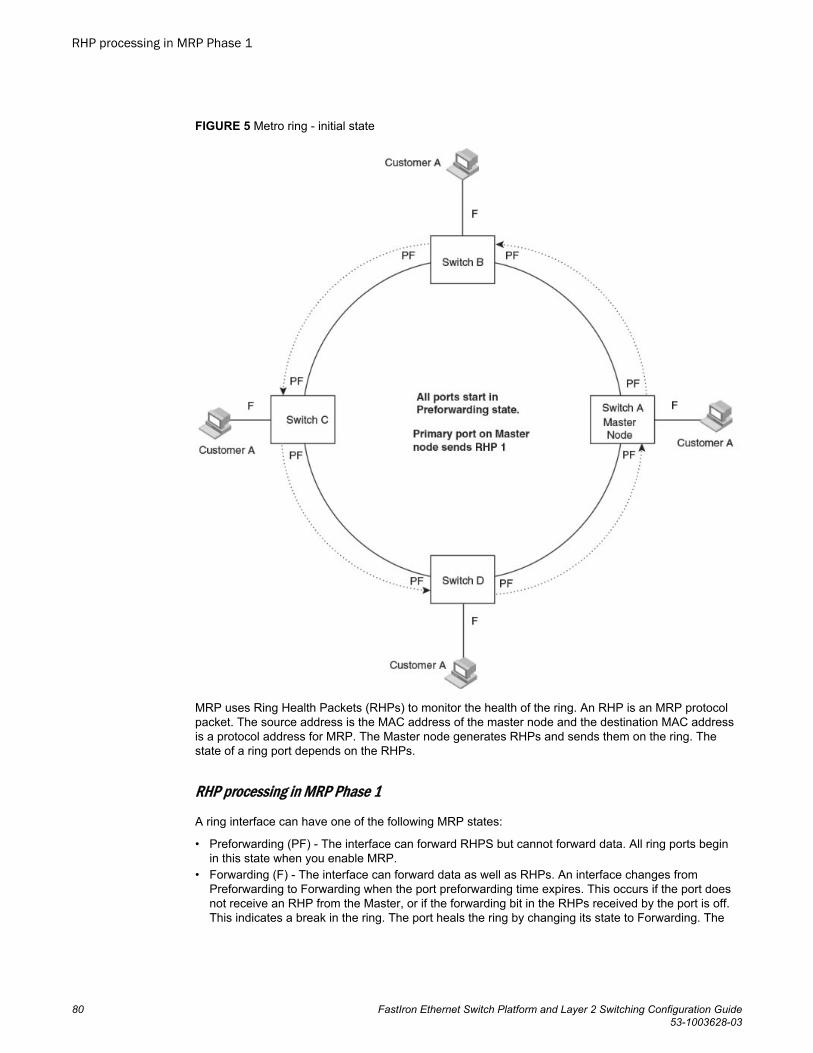
FIGURE 5 Metro ring - initial state
MRP uses Ring Health Packets (RHPs) to monitor the health of the ring. An RHP is an MRP protocolpacket. The source address is the MAC address of the master node and the destination MAC addressis a protocol address for MRP. The Master node generates RHPs and sends them on the ring. Thestate of a ring port depends on the RHPs.
RHP processing in MRP Phase 1
A ring interface can have one of the following MRP states:
• Preforwarding (PF) - The interface can forward RHPS but cannot forward data. All ring ports beginin this state when you enable MRP.
• Forwarding (F) - The interface can forward data as well as RHPs. An interface changes fromPreforwarding to Forwarding when the port preforwarding time expires. This occurs if the port doesnot receive an RHP from the Master, or if the forwarding bit in the RHPs received by the port is off.This indicates a break in the ring. The port heals the ring by changing its state to Forwarding. The
RHP processing in MRP Phase 1
80 FastIron Ethernet Switch Platform and Layer 2 Switching Configuration Guide53-1003628-03
preforwarding time is the number of milliseconds the port will remain in the Preforwarding statebefore changing to the Forwarding state, even without receiving an RHP.
• Blocking (B) - The interface cannot forward data. Only the secondary interface on the Master nodecan be Blocking.
When MRP is enabled, all ports begin in the Preforwarding state. The primary interface on the Masternode, although it is in the Preforwarding state like the other ports, immediately sends an RHP onto thering. The secondary port on the Master node listens for the RHP.
• If the secondary port receives the RHP, all links in the ring are up and the port changes its state toBlocking. The primary port then sends another MRP with its forwarding bit set on. As each of themember ports receives the RHP, the ports changes their state to Forwarding. Typically, this occurs insub-second time. The ring very quickly enters the fully initialized state.
• If the secondary port does not receive the RHP by the time the preforwarding time expires, a breakhas occurred in the ring. The port changes its state to Forwarding. The member ports also changetheir states from Preforwarding to Forwarding as their preforwarding timers expire. The ring is notintact, but data can still travel among the nodes using the links that are up.
The following figure shows an example.
Metro Features
FastIron Ethernet Switch Platform and Layer 2 Switching Configuration Guide 8153-1003628-03
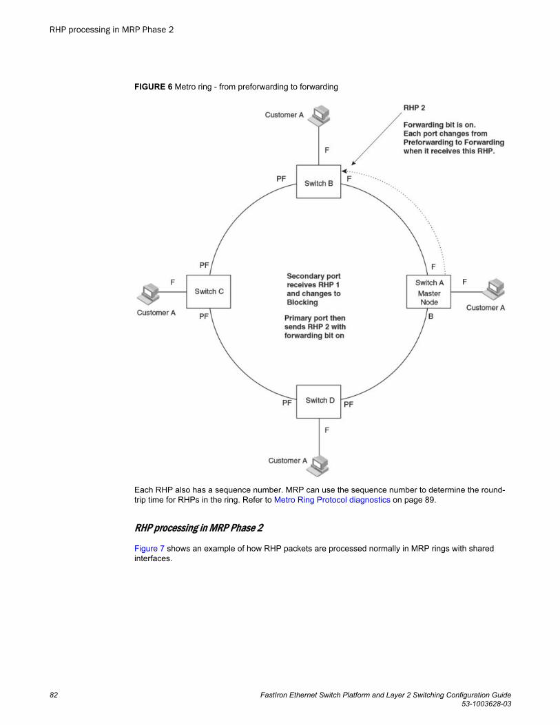
FIGURE 6 Metro ring - from preforwarding to forwarding
Each RHP also has a sequence number. MRP can use the sequence number to determine the round-trip time for RHPs in the ring. Refer to Metro Ring Protocol diagnostics on page 89.
RHP processing in MRP Phase 2
Figure 7 shows an example of how RHP packets are processed normally in MRP rings with sharedinterfaces.
RHP processing in MRP Phase 2
82 FastIron Ethernet Switch Platform and Layer 2 Switching Configuration Guide53-1003628-03
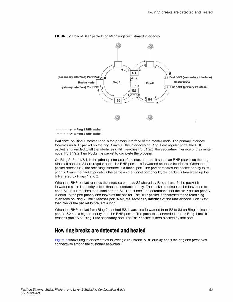
FIGURE 7 Flow of RHP packets on MRP rings with shared interfaces
Port 1/2/1 on Ring 1 master node is the primary interface of the master node. The primary interfaceforwards an RHP packet on the ring. Since all the interfaces on Ring 1 are regular ports, the RHPpacket is forwarded to all the interfaces until it reaches Port 1/2/2, the secondary interface of the masternode. Port 1/2/2 then blocks the packet to complete the process.
On Ring 2, Port 1/3/1, is the primary interface of the master node. It sends an RHP packet on the ring.Since all ports on S4 are regular ports, the RHP packet is forwarded on those interfaces. When thepacket reaches S2, the receiving interface is a tunnel port. The port compares the packet priority to itspriority. Since the packet priority is the same as the tunnel port priority, the packet is forwarded up thelink shared by Rings 1 and 2.
When the RHP packet reaches the interface on node S2 shared by Rings 1 and 2, the packet isforwarded since its priority is less than the interface priority. The packet continues to be forwarded tonode S1 until it reaches the tunnel port on S1. That tunnel port determines that the RHP packet priorityis equal to the port priority and forwards the packet. The RHP packet is forwarded to the remaininginterfaces on Ring 2 until it reaches port 1/3/2, the secondary interface of the master node. Port 1/3/2then blocks the packet to prevent a loop.
When the RHP packet from Ring 2 reached S2, it was also forwarded from S2 to S3 on Ring 1 since theport on S2 has a higher priority than the RHP packet. The packets is forwarded around Ring 1 until itreaches port 1/2/2, Ring 1 the secondary port. The RHP packet is then blocked by that port.
How ring breaks are detected and healedFigure 8 shows ring interface states following a link break. MRP quickly heals the ring and preservesconnectivity among the customer networks.
How ring breaks are detected and healed
FastIron Ethernet Switch Platform and Layer 2 Switching Configuration Guide 8353-1003628-03
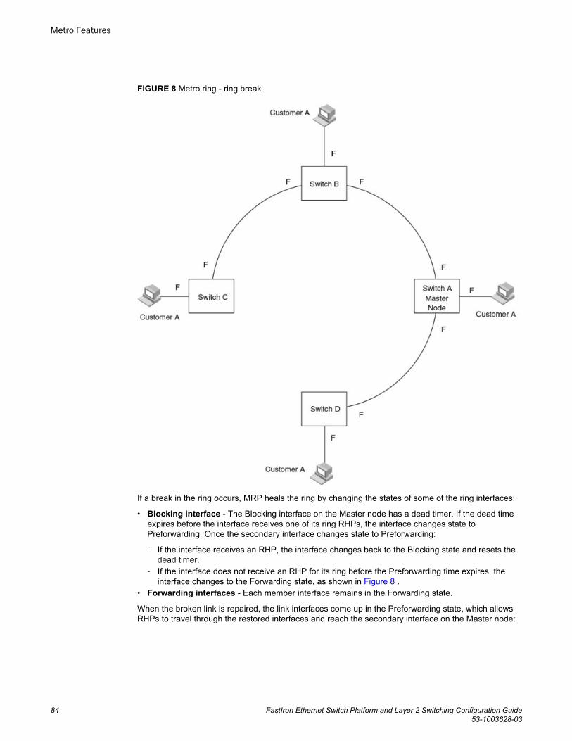
FIGURE 8 Metro ring - ring break
If a break in the ring occurs, MRP heals the ring by changing the states of some of the ring interfaces:
• Blocking interface - The Blocking interface on the Master node has a dead timer. If the dead timeexpires before the interface receives one of its ring RHPs, the interface changes state toPreforwarding. Once the secondary interface changes state to Preforwarding:
‐ If the interface receives an RHP, the interface changes back to the Blocking state and resets thedead timer.
‐ If the interface does not receive an RHP for its ring before the Preforwarding time expires, theinterface changes to the Forwarding state, as shown in Figure 8 .
• Forwarding interfaces - Each member interface remains in the Forwarding state.
When the broken link is repaired, the link interfaces come up in the Preforwarding state, which allowsRHPs to travel through the restored interfaces and reach the secondary interface on the Master node:
Metro Features
84 FastIron Ethernet Switch Platform and Layer 2 Switching Configuration Guide53-1003628-03
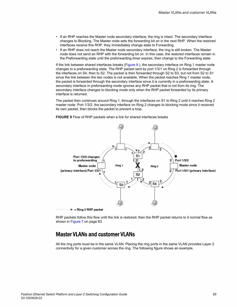
• If an RHP reaches the Master node secondary interface, the ring is intact. The secondary interfacechanges to Blocking. The Master node sets the forwarding bit on in the next RHP. When the restoredinterfaces receive this RHP, they immediately change state to Forwarding.
• If an RHP does not reach the Master node secondary interface, the ring is still broken. The Masternode does not send an RHP with the forwarding bit on. In this case, the restored interfaces remain inthe Preforwarding state until the preforwarding timer expires, then change to the Forwarding state.
If the link between shared interfaces breaks (Figure 9 ), the secondary interface on Ring 1 master nodechanges to a preforwarding state. The RHP packet sent by port 1/3/1 on Ring 2 is forwarded throughthe interfaces on S4, then to S2. The packet is then forwarded through S2 to S3, but not from S2 to S1since the link between the two nodes is not available. When the packet reaches Ring 1 master node,the packet is forwarded through the secondary interface since it is currently in a preforwarding state. Asecondary interface in preforwarding mode ignores any RHP packet that is not from its ring. Thesecondary interface changes to blocking mode only when the RHP packet forwarded by its primaryinterface is returned.
The packet then continues around Ring 1, through the interfaces on S1 to Ring 2 until it reaches Ring 2master node. Port 1/3/2, the secondary interface on Ring 2 changes to blocking mode since it receivedits own packet, then blocks the packet to prevent a loop.
FIGURE 9 Flow of RHP packets when a link for shared interfaces breaks
RHP packets follow this flow until the link is restored; then the RHP packet returns to it normal flow asshown in Figure 7 on page 83.
Master VLANs and customer VLANsAll the ring ports must be in the same VLAN. Placing the ring ports in the same VLAN provides Layer 2connectivity for a given customer across the ring. The following figure shows an example.
Master VLANs and customer VLANs
FastIron Ethernet Switch Platform and Layer 2 Switching Configuration Guide 8553-1003628-03
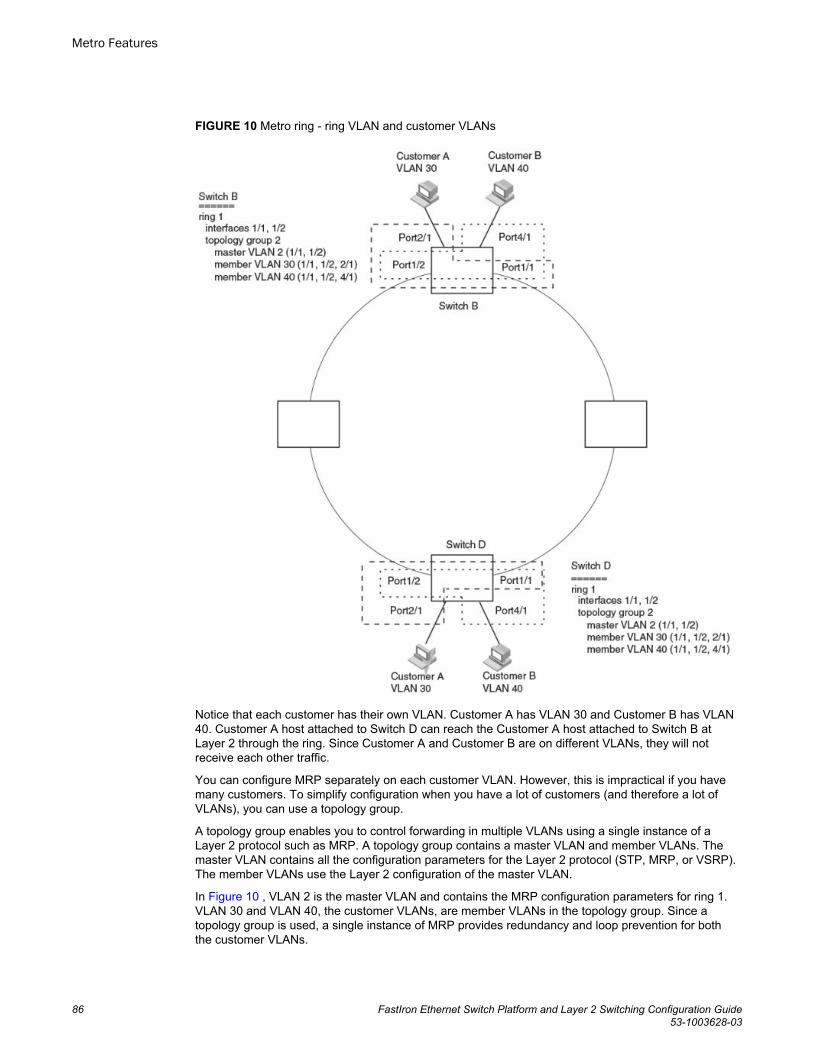
FIGURE 10 Metro ring - ring VLAN and customer VLANs
Notice that each customer has their own VLAN. Customer A has VLAN 30 and Customer B has VLAN40. Customer A host attached to Switch D can reach the Customer A host attached to Switch B atLayer 2 through the ring. Since Customer A and Customer B are on different VLANs, they will notreceive each other traffic.
You can configure MRP separately on each customer VLAN. However, this is impractical if you havemany customers. To simplify configuration when you have a lot of customers (and therefore a lot ofVLANs), you can use a topology group.
A topology group enables you to control forwarding in multiple VLANs using a single instance of aLayer 2 protocol such as MRP. A topology group contains a master VLAN and member VLANs. Themaster VLAN contains all the configuration parameters for the Layer 2 protocol (STP, MRP, or VSRP).The member VLANs use the Layer 2 configuration of the master VLAN.
In Figure 10 , VLAN 2 is the master VLAN and contains the MRP configuration parameters for ring 1.VLAN 30 and VLAN 40, the customer VLANs, are member VLANs in the topology group. Since atopology group is used, a single instance of MRP provides redundancy and loop prevention for boththe customer VLANs.
Metro Features
86 FastIron Ethernet Switch Platform and Layer 2 Switching Configuration Guide53-1003628-03
If you use a topology group:
• The master VLAN must contain the ring interfaces. The ports must be tagged, since they will beshared by multiple VLANs.
• The member VLAN for a customer must contain the two ring interfaces and the interfaces for thecustomer. Since these interfaces are shared with the master VLAN, they must be tagged. Do not addanother customer interfaces to the VLAN.
For more information about topology groups, refer to Topology groups on page 71.
Refer to MRP CLI example on page 93 for the configuration commands required to implement theMRP configuration shown in Figure 10 .
Metro Ring Protocol configurationTo configure Metro Ring Protocol (MRP), perform the following tasks. You need to perform the first taskon only one of the nodes. Perform the remaining tasks on all the nodes.
NOTEThere are no new commands or parameters to configure MRP with shared interfaces (MRP Phase 2).
• Disable one of the ring interfaces. This prevents a Layer 2 loop from occurring while you areconfiguring the devices for MRP.
• Add an MRP ring to a port-based VLAN. When you add a ring, the CLI changes to the configurationlevel for the ring, where you can perform the following tasks.
‐ Optionally, specify a name for the ring.‐ On the master node only, enable the device to be the master for the ring. Each ring can have only
one master node.‐ Specify the MRP interfaces. Each device has two interfaces to an MRP ring.‐ Optionally, change the hello time and the preforwarding time. These parameters control how
quickly failover occurs following a change in the state of a link in the ring.‐ Enable the ring.
• Optionally, add the ring VLAN to a topology group to add more VLANs to the ring. If you use atopology group, make sure you configure MRP on the group master VLAN. Refer to Topology groupson page 71.
• Re-enable the interface you disabled to prevent a Layer 2 loop. Once MRP is enabled, MRP willprevent the Layer 2 loop.
• On FCX devices, when configuring MRP-1 or MRP-2 rings on a VLAN, using the metro-ringscommand in addition to the metro-ring command is highly recommended. Since these devices donot support mac-range filtering, the metro-rings command greatly reduces the number of FDBentries.
Adding an MRP ring to a VLAN
To add an MRP ring to a VLAN, enter commands such as the following.
NOTEIf you plan to use a topology group to add VLANs to the ring, make sure you configure MRP on thetopology group master VLAN.
device(config)#vlan 2device(config-vlan-2)#metro-ring 1device(config-vlan-2-mrp-1)#name CustomerA
Metro Ring Protocol configuration
FastIron Ethernet Switch Platform and Layer 2 Switching Configuration Guide 8753-1003628-03

device(config-vlan-2-mrp-1)#masterdevice(config-vlan-2-mrp-1)#ring-interface ethernet 1/1/1 ethernet 1/1/2device(config-vlan-2-mrp-1)#enableThese commands configure an MRP ring on VLAN 2. The ring ID is 1, the ring name is CustomerA,and this node (this Brocade device) is the master for the ring. The ring interfaces are 1/1/1 and 1/1/2.Interface 1/1/1 is the primary interface and 1/1/2 is the secondary interface. The primary interface willinitiate RHPs by default. The ring takes effect in VLAN 2.
device(config)#vlan 2device(config-vlan-2)#metro-ring 1device(config-vlan-2-mrp-1)#name CustomerAdevice(config-vlan-2-mrp-1)#ring-interface ethernet 1/1/1 ethernet 1/1/2device(config-vlan-2-mrp-1)#enabledevice(config-vlan-2-mrp-1)#metro-ring 2 device(config-vlan-2-mrp-2)#name CustomerB device(config-vlan-2-mrp-2)#ring-interface ethernet 1/1/1 ethernet 1/1/2device(config-vlan-2-mrp-2)#enableSyntax: [no] metro-ring ring id
The ring-id parameter specifies the ring ID. The ring-id can be from 1 - 1023; ID 256 is reserved forVSRP.
On FCX and ICX devices, enter the metro-rings in addition to the metro-ring command as shownbelow.
device(config)#vlan 2device(config-vlan-2)#metro-rings 1 2device(config-vlan-2)#metro-ring 1device(config-vlan-2-mrp-1)#name CustomerAdevice(config-vlan-2-mrp-1)#ring-interface ethernet 1/1/1 ethernet 1/1/2device(config-vlan-2-mrp-1)#enabledevice(config-vlan-2-mrp-1)#metro-ring 2device(config-vlan-2-mrp-2)#name CustomerBdevice(config-vlan-2-mrp-2)#ring-interface ethernet 1/1/1 ethernet 1/1/2device(config-vlan-2-mrp-2)#enableSyntax: [no] metro-rings ringid ringid . ..
The ring id variables identify the metro rings you want to configure on the VLAN.
Syntax: [no] name string
The string parameter specifies a name for the ring. The name is optional, but it can be up to 20characters long and can include blank spaces. If you use a name that has blank spaces, enclose thename in double quotation marks (for example: "Customer A").
Syntax: [no] master
Configures this node as the master node for the ring. Enter this command only on one node in thering. The node is a member (non-master) node by default.
Syntax: [no] ring-interface ethernet primary-if ethernet secondary-if
The ethernet primary-if parameter specifies the primary interface. On the master node, the primaryinterface is the one that originates RHPs. Ring control traffic and Layer 2 data traffic will flow in theoutward direction from this interface by default. On member nodes, the direction of traffic flow dependson the traffic direction selected by the master node. Therefore, on a member node, the order in whichyou enter the interfaces does not matter.
The ethernet secondary-if parameter specifies the secondary interface.
NOTETo take advantage of every interface in a Metro network, you can configure another MRP ring andeither configure a different Master node for the ring or reverse the configuration of the primary and
Metro Features
88 FastIron Ethernet Switch Platform and Layer 2 Switching Configuration Guide53-1003628-03
secondary interfaces on the Master node. Configuring multiple rings enables you to use all the ports inthe ring. The same port can forward traffic one ring while blocking traffic for another ring.
Syntax: [no] enable
The enable command enables the ring.
Changing the hello and preforwarding times
You also can change the RHP hello time and preforwarding time. To do so, enter commands such asthe following.
device(config-vlan-2-mrp-1)#hello-time 200device(config-vlan-2-mrp-1)#preforwarding-time 400These commands change the hello time to 200 ms and change the preforwarding time to 400 ms.
Syntax: [no] hello-time ms
Syntax: [no] preforwarding-time ms
The ms specifies the number of milliseconds. For the hello time, you can specify from 100 - 1000 (onesecond). The default hello time is 100 ms. The preforwarding time can be from 200 - 5000 ms, but mustbe at least twice the value of the hello time and must be a multiple of the hello time. The defaultpreforwarding time is 300 ms. A change to the hello time or preforwarding time takes effect as soon asyou enter the command.
Configuration notes for changing the hello and preforwarding times
• The preforwarding time must be at least twice the value of the hello time and must be a multiple ofthe hello time.
• If UDLD is also enabled on the device, Brocade recommends that you set the MRP preforwardingtime slightly higher than the default of 300 ms; for example, to 400 or 500 ms.
• You can use MRP ring diagnostics to determine whether you need to change the hello time andpreforwarding time. Refer to Metro Ring Protocol diagnostics on page 89.
Metro Ring Protocol diagnosticsThe Metro Ring Protocol (MRP) diagnostics feature calculates how long it takes for RHP packets totravel through the ring. When you enable MRP diagnostics, the software tracks RHP packets accordingto their sequence numbers and calculates how long it takes an RHP packet to travel one time throughthe entire ring. When you display the diagnostics, the CLI shows the average round-trip time for theRHP packets sent since you enabled diagnostics. The calculated results have a granularity of 1microsecond.
Enabling MRP diagnostics
To enable MRP diagnostics for a ring, enter the following command on the Master node, at theconfiguration level for the ring.
device(config-vlan-2-mrp-1)#diagnosticsSyntax: [no] diagnostics
Changing the hello and preforwarding times
FastIron Ethernet Switch Platform and Layer 2 Switching Configuration Guide 8953-1003628-03
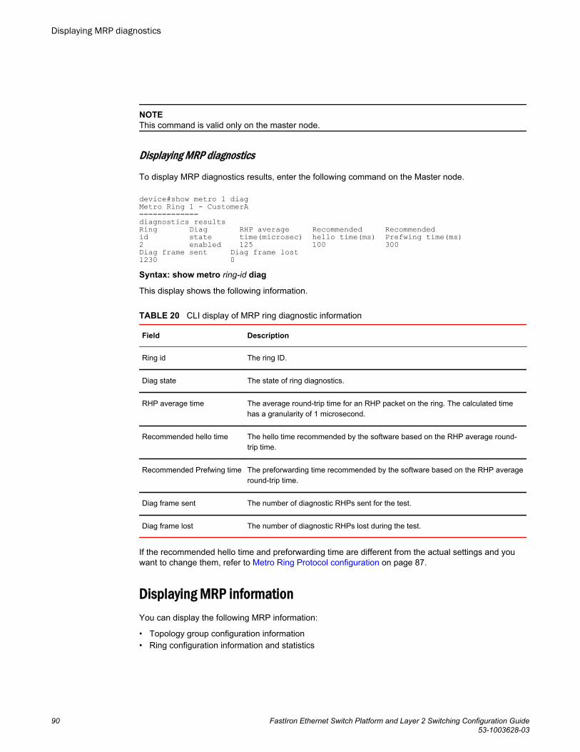
NOTEThis command is valid only on the master node.
Displaying MRP diagnostics
To display MRP diagnostics results, enter the following command on the Master node.
device#show metro 1 diagMetro Ring 1 - CustomerA=============diagnostics resultsRing Diag RHP average Recommended Recommendedid state time(microsec) hello time(ms) Prefwing time(ms)2 enabled 125 100 300Diag frame sent Diag frame lost1230 0Syntax: show metro ring-id diag
This display shows the following information.
CLI display of MRP ring diagnostic information TABLE 20
Field Description
Ring id The ring ID.
Diag state The state of ring diagnostics.
RHP average time The average round-trip time for an RHP packet on the ring. The calculated timehas a granularity of 1 microsecond.
Recommended hello time The hello time recommended by the software based on the RHP average round-trip time.
Recommended Prefwing time The preforwarding time recommended by the software based on the RHP averageround-trip time.
Diag frame sent The number of diagnostic RHPs sent for the test.
Diag frame lost The number of diagnostic RHPs lost during the test.
If the recommended hello time and preforwarding time are different from the actual settings and youwant to change them, refer to Metro Ring Protocol configuration on page 87.
Displaying MRP informationYou can display the following MRP information:
• Topology group configuration information• Ring configuration information and statistics
Displaying MRP diagnostics
90 FastIron Ethernet Switch Platform and Layer 2 Switching Configuration Guide53-1003628-03
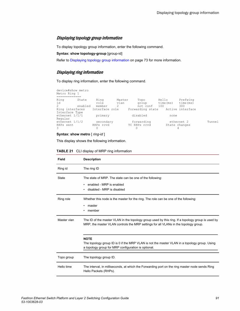
Displaying topology group information
To display topology group information, enter the following command.
Syntax: show topology-group [group-id]
Refer to Displaying topology group information on page 73 for more information.
Displaying ring information
To display ring information, enter the following command.
device#show metroMetro Ring 1=============Ring State Ring Master Topo Hello Prefwingid role vlan group time(ms) time(ms)2 enabled member 2 not conf 100 300Ring interfaces Interface role Forwarding state Active interface Interface Typeethernet 1/1/1 primary disabled none Regularethernet 1/1/2 secondary forwarding ethernet 2 TunnelRHPs sent RHPs rcvd TC RHPs rcvd State changes3 0 0 4Syntax: show metro [ ring-id ]
This display shows the following information.
CLI display of MRP ring information TABLE 21
Field Description
Ring id The ring ID
State The state of MRP. The state can be one of the following:
• enabled - MRP is enabled• disabled - MRP is disabled
Ring role Whether this node is the master for the ring. The role can be one of the following:
• master• member
Master vlan The ID of the master VLAN in the topology group used by this ring. If a topology group is used byMRP, the master VLAN controls the MRP settings for all VLANs in the topology group.
NOTEThe topology group ID is 0 if the MRP VLAN is not the master VLAN in a topology group. Usinga topology group for MRP configuration is optional.
Topo group The topology group ID.
Hello time The interval, in milliseconds, at which the Forwarding port on the ring master node sends RingHello Packets (RHPs).
Displaying topology group information
FastIron Ethernet Switch Platform and Layer 2 Switching Configuration Guide 9153-1003628-03
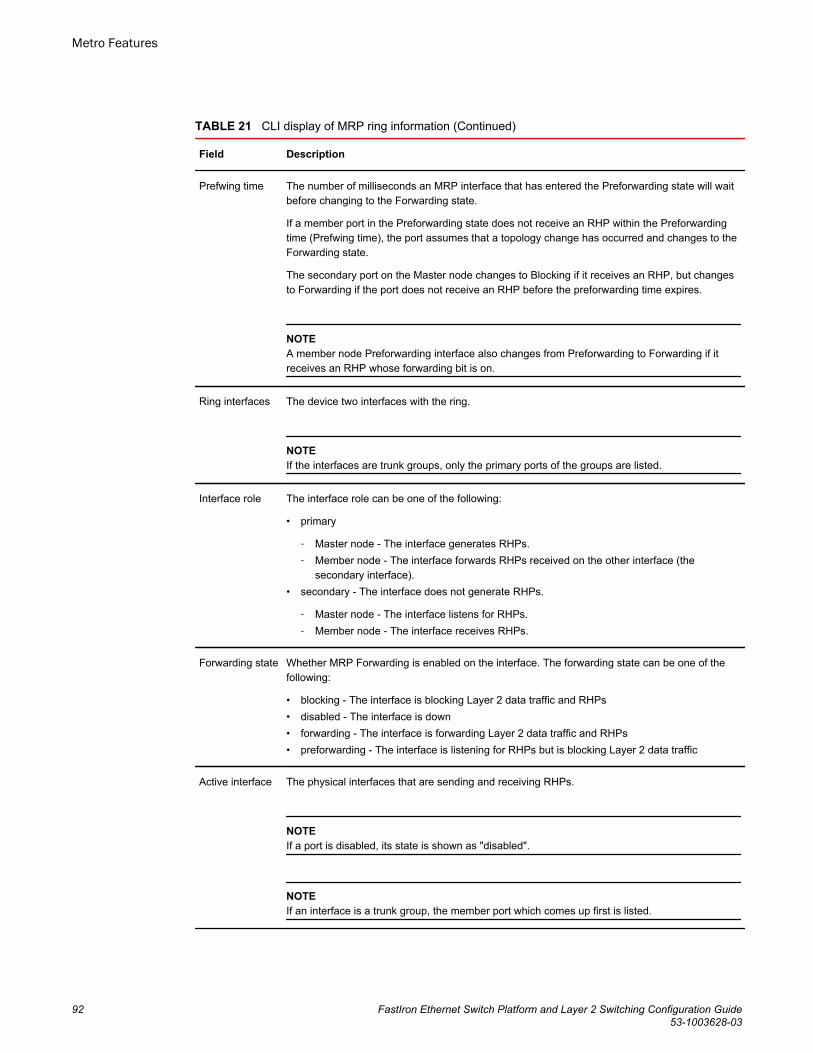
CLI display of MRP ring information (Continued)TABLE 21
Field Description
Prefwing time The number of milliseconds an MRP interface that has entered the Preforwarding state will waitbefore changing to the Forwarding state.
If a member port in the Preforwarding state does not receive an RHP within the Preforwardingtime (Prefwing time), the port assumes that a topology change has occurred and changes to theForwarding state.
The secondary port on the Master node changes to Blocking if it receives an RHP, but changesto Forwarding if the port does not receive an RHP before the preforwarding time expires.
NOTEA member node Preforwarding interface also changes from Preforwarding to Forwarding if itreceives an RHP whose forwarding bit is on.
Ring interfaces The device two interfaces with the ring.
NOTEIf the interfaces are trunk groups, only the primary ports of the groups are listed.
Interface role The interface role can be one of the following:
• primary
‐ Master node - The interface generates RHPs.‐ Member node - The interface forwards RHPs received on the other interface (the
secondary interface).• secondary - The interface does not generate RHPs.
‐ Master node - The interface listens for RHPs.‐ Member node - The interface receives RHPs.
Forwarding state Whether MRP Forwarding is enabled on the interface. The forwarding state can be one of thefollowing:
• blocking - The interface is blocking Layer 2 data traffic and RHPs• disabled - The interface is down• forwarding - The interface is forwarding Layer 2 data traffic and RHPs• preforwarding - The interface is listening for RHPs but is blocking Layer 2 data traffic
Active interface The physical interfaces that are sending and receiving RHPs.
NOTEIf a port is disabled, its state is shown as "disabled".
NOTEIf an interface is a trunk group, the member port which comes up first is listed.
Metro Features
92 FastIron Ethernet Switch Platform and Layer 2 Switching Configuration Guide53-1003628-03
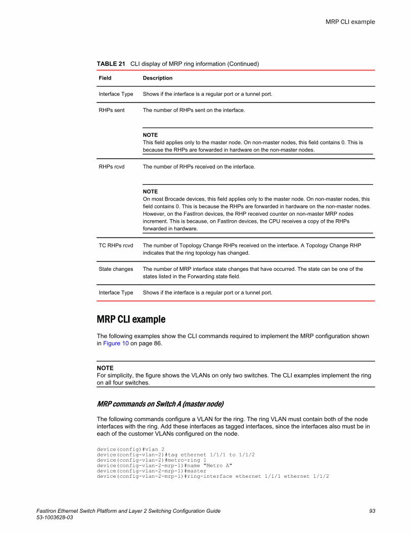
CLI display of MRP ring information (Continued)TABLE 21
Field Description
Interface Type Shows if the interface is a regular port or a tunnel port.
RHPs sent The number of RHPs sent on the interface.
NOTEThis field applies only to the master node. On non-master nodes, this field contains 0. This isbecause the RHPs are forwarded in hardware on the non-master nodes.
RHPs rcvd The number of RHPs received on the interface.
NOTEOn most Brocade devices, this field applies only to the master node. On non-master nodes, thisfield contains 0. This is because the RHPs are forwarded in hardware on the non-master nodes.However, on the FastIron devices, the RHP received counter on non-master MRP nodesincrement. This is because, on FastIron devices, the CPU receives a copy of the RHPsforwarded in hardware.
TC RHPs rcvd The number of Topology Change RHPs received on the interface. A Topology Change RHPindicates that the ring topology has changed.
State changes The number of MRP interface state changes that have occurred. The state can be one of thestates listed in the Forwarding state field.
Interface Type Shows if the interface is a regular port or a tunnel port.
MRP CLI exampleThe following examples show the CLI commands required to implement the MRP configuration shownin Figure 10 on page 86.
NOTEFor simplicity, the figure shows the VLANs on only two switches. The CLI examples implement the ringon all four switches.
MRP commands on Switch A (master node)
The following commands configure a VLAN for the ring. The ring VLAN must contain both of the nodeinterfaces with the ring. Add these interfaces as tagged interfaces, since the interfaces also must be ineach of the customer VLANs configured on the node.
device(config)#vlan 2device(config-vlan-2)#tag ethernet 1/1/1 to 1/1/2device(config-vlan-2)#metro-ring 1device(config-vlan-2-mrp-1)#name "Metro A"device(config-vlan-2-mrp-1)#masterdevice(config-vlan-2-mrp-1)#ring-interface ethernet 1/1/1 ethernet 1/1/2
MRP CLI example
FastIron Ethernet Switch Platform and Layer 2 Switching Configuration Guide 9353-1003628-03
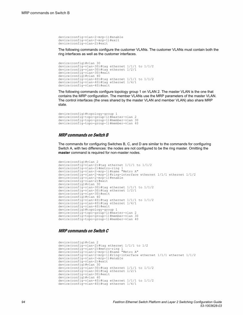
device(config-vlan-2-mrp-1)#enabledevice(config-vlan-2-mrp-1)#exitdevice(config-vlan-2)#exitThe following commands configure the customer VLANs. The customer VLANs must contain both thering interfaces as well as the customer interfaces.
device(config)#vlan 30device(config-vlan-30)#tag ethernet 1/1/1 to 1/1/2device(config-vlan-30)#tag ethernet 1/2/1device(config-vlan-30)#exitdevice(config)#vlan 40device(config-vlan-40)#tag ethernet 1/1/1 to 1/1/2device(config-vlan-40)#tag ethernet 1/4/1device(config-vlan-40)#exitThe following commands configure topology group 1 on VLAN 2. The master VLAN is the one thatcontains the MRP configuration. The member VLANs use the MRP parameters of the master VLAN.The control interfaces (the ones shared by the master VLAN and member VLAN) also share MRPstate.
device(config)#topology-group 1device(config-topo-group-1)#master-vlan 2device(config-topo-group-1)#member-vlan 30device(config-topo-group-1)#member-vlan 40
MRP commands on Switch B
The commands for configuring Switches B, C, and D are similar to the commands for configuringSwitch A, with two differences: the nodes are not configured to be the ring master. Omitting themaster command is required for non-master nodes.
device(config)#vlan 2device(config-vlan-2)#tag ethernet 1/1/1 to 1/1/2device(config-vlan-2)#metro-ring 1device(config-vlan-2-mrp-1)#name "Metro A"device(config-vlan-2-mrp-1)#ring-interface ethernet 1/1/1 ethernet 1/1/2device(config-vlan-2-mrp-1)#enabledevice(config-vlan-2)#exitdevice(config)#vlan 30device(config-vlan-30)#tag ethernet 1/1/1 to 1/1/2device(config-vlan-30)#tag ethernet 1/2/1device(config-vlan-30)#exitdevice(config)#vlan 40device(config-vlan-40)#tag ethernet 1/1/1 to 1/1/2device(config-vlan-40)#tag ethernet 1/4/1device(config-vlan-40)#exitdevice(config)#topology-group 1device(config-topo-group-1)#master-vlan 2device(config-topo-group-1)#member-vlan 30device(config-topo-group-1)#member-vlan 40
MRP commands on Switch C
device(config)#vlan 2device(config-vlan-2)#tag ethernet 1/1/1 to 1/2device(config-vlan-2)#metro-ring 1device(config-vlan-2-mrp-1)#name "Metro A"device(config-vlan-2-mrp-1)#ring-interface ethernet 1/1/1 ethernet 1/1/2device(config-vlan-2-mrp-1)#enabledevice(config-vlan-2)#exitdevice(config)#vlan 30device(config-vlan-30)#tag ethernet 1/1/1 to 1/1/2device(config-vlan-30)#tag ethernet 1/2/1device(config-vlan-30)#exitdevice(config)#vlan 40device(config-vlan-40)#tag ethernet 1/1/1 to 1/1/2device(config-vlan-40)#tag ethernet 1/4/1
MRP commands on Switch B
94 FastIron Ethernet Switch Platform and Layer 2 Switching Configuration Guide53-1003628-03
device(config-vlan-40)#exitdevice(config)#topology-group 1device(config-topo-group-1)#master-vlan 2device(config-topo-group-1)#member-vlan 30device(config-topo-group-1)#member-vlan 40
MRP commands on Switch D
device(config)#vlan 2device(config-vlan-2)#tag ethernet 1/1/1 to 1/1/2device(config-vlan-2)#metro-ring 1device(config-vlan-2-mrp-1)#name "Metro A"device(config-vlan-2-mrp-1)#ring-interface ethernet 1/1/1 ethernet 1/1/2device(config-vlan-2-mrp-1)#enabledevice(config-vlan-2)#exitdevice(config)#vlan 30device(config-vlan-30)#tag ethernet 1/1/1 to 1/1/2device(config-vlan-30)#tag ethernet 1/2/1device(config-vlan-30)#exitdevice(config)#vlan 40device(config-vlan-40)#tag ethernet 1/1/1 to 1/1/2device(config-vlan-40)#tag ethernet 1/4/1device(config-vlan-40)#exitdevice(config)#topology-group 1device(config-topo-group-1)#master-vlan 2device(config-topo-group-1)#member-vlan 30device(config-topo-group-1)#member-vlan 40
VSRPVirtual Switch Redundancy Protocol (VSRP) is a Brocade proprietary protocol that provides redundancyand sub-second failover in Layer 2 and Layer 3 mesh topologies. Based on the Brocade Virtual RouterRedundancy Protocol Extended (VRRP-E), VSRP provides one or more backups for a Layer 2 Switchor Layer 3 Switch. If the active Layer 2 Switch or Layer 3 Switch becomes unavailable, one of thebackups takes over as the active device and continues forwarding traffic for the network.
The FastIron family of switches support full VSRP as well as VSRP-awareness . A Brocade device thatis not itself configured for VSRP but is connected to a Brocade device that is configured for VSRP, isVSRP aware .
NOTEVSRP protocol is not supported on the Brocade ICX 6430-C devices. Only VSRP-awareness issupported.
You can use VSRP for Layer 2, Layer 3, or for both layers. On Layer 3 Switches, Layer 2 and Layer 3share the same VSRP configuration information. On Layer 2 Switches, VSRP applies only to Layer 2.
The following example shows an example of a VSRP configuration.
MRP commands on Switch D
FastIron Ethernet Switch Platform and Layer 2 Switching Configuration Guide 9553-1003628-03
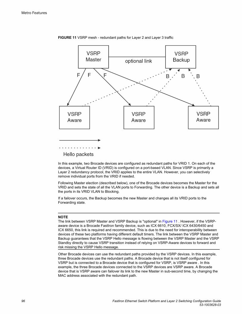
FIGURE 11 VSRP mesh - redundant paths for Layer 2 and Layer 3 traffic
In this example, two Brocade devices are configured as redundant paths for VRID 1. On each of thedevices, a Virtual Router ID (VRID) is configured on a port-based VLAN. Since VSRP is primarily aLayer 2 redundancy protocol, the VRID applies to the entire VLAN. However, you can selectivelyremove individual ports from the VRID if needed.
Following Master election (described below), one of the Brocade devices becomes the Master for theVRID and sets the state of all the VLAN ports to Forwarding. The other device is a Backup and sets allthe ports in its VRID VLAN to Blocking.
If a failover occurs, the Backup becomes the new Master and changes all its VRID ports to theForwarding state.
NOTEThe link between VSRP Master and VSRP Backup is "optional" in Figure 11 . However, if the VSRP-aware device is a Brocade FastIron family device, such as ICX 6610, FCX/SX/ ICX 6430/6450 andICX 6650, this link is required and recommended. This is due to the need for interoperability betweendevices of these two platforms having different default timers. The link between the VSRP Master andBackup guarantees that the VSRP Hello message is flowing between the VSRP Master and the VSRPStandby directly to cause VSRP transition instead of relying on VSRP-Aware devices to forward andrisk missing the VSRP Hello message.
Other Brocade devices can use the redundant paths provided by the VSRP devices. In this example,three Brocade devices use the redundant paths. A Brocade device that is not itself configured forVSRP but is connected to a Brocade device that is configured for VSRP, is VSRP aware . In thisexample, the three Brocade devices connected to the VSRP devices are VSRP aware. A Brocadedevice that is VSRP aware can failover its link to the new Master in sub-second time, by changing theMAC address associated with the redundant path.
Metro Features
96 FastIron Ethernet Switch Platform and Layer 2 Switching Configuration Guide53-1003628-03
When you configure VSRP, make sure each of the non-VSRP Brocade devices connected to the VSRPdevices has a separate link to each of the VSRP devices.
VSRP configuration notes and feature limitations• VSRP and 802.1Q-n-Q tagging are not supported together on the same device.• VSRP and Super Aggregated VLANs are not supported together on the same device.
NOTE802.1Q-n-Q tagging and Aggregated VLANs are not supported on the Brocade ICX 6430-C devices.
• The VLAN supports IGMP snooping version 2 and version 3 when VSRP or VSRP-aware isconfigured on a VLAN.
Layer 2 and Layer 3 redundancyYou can configure VSRP to provide redundancy for Layer 2 only or also for Layer 3:
• Layer 2 only - The Layer 2 links are backed up but specific IP addresses are not backed up.• Layer 2 and Layer 3 - The Layer 2 links are backed up and a specific IP address is also backed up.
Layer 3 VSRP is the same as VRRP-E. However, using VSRP provides redundancy at both layers atthe same time.
Layer 2 Switches support Layer 2 VSRP only. Layer 3 Switches support Layer 2 and Layer 3redundancy. You can configure a Layer 3 Switch for either Layer 2 only or Layer 2 and Layer 3. Toconfigure for Layer 3, specify the IP address you are backing up.
NOTEIf you want to provide Layer 3 redundancy only, disable VSRP and use VRRP-E.
Master election and failoverEach VSRP device advertises its VSRP priority in Hello messages. During Master election, the VSRPdevice with the highest priority for a given VRID becomes the Master for that VRID. After Masterelection, the Master sends Hello messages at regular intervals to inform the Backups that the Master ishealthy.
If there is a tie for highest VSRP priority, the tie is resolved as follows:
• Layer 2 Switches - The Layer 2 Switch with the higher management IP address becomes the Master.
‐ Switches with management IP addresses are preferred over switches without management IPaddresses.
‐ If neither of the switches has a management IP address, then the switch with the higher MACaddress becomes the Master. (VSRP compares the MAC addresses of the ports configured for theVRID, not the base MAC addresses of the switches.)
• Layer 3 Switches - The Layer 3 Switch whose virtual routing interface has a higher IP addressbecomes the master.
VSRP configuration notes and feature limitations
FastIron Ethernet Switch Platform and Layer 2 Switching Configuration Guide 9753-1003628-03
VSRP failover
Each Backup listens for Hello messages from the Master. The Hello messages indicate that theMaster is still available. If the Backups stop receiving Hello messages from the Master, the electionprocess occurs again and the Backup with the highest priority becomes the new Master.
Each Backup waits for a specific period of time, the Dead Interval, to receive a new Hello messagefrom the Master. If the Backup does not receive a Hello message from the Master by the time theDead Interval expires, the Backup sends a Hello message of its own, which includes the Backup'sVSRP priority, to advertise the Backup's intent to become the Master. If there are multiple Backups forthe VRID, each Backup sends a Hello message.
When a Backup sends a Hello message announcing its intent to become the Master, the Backup alsostarts a hold-down timer. During the hold-down time, the Backup listens for a Hello message with ahigher priority than its own.
• If the Backup receives a Hello message with a higher priority than its own, the Backup resets itsDead Interval and returns to normal Backup status.
• If the Backup does not receive a Hello message with a higher priority than its own by the time thehold-down timer expires, the Backup becomes the new Master and starts forwarding Layer 2 trafficon all ports.
If you increase the timer scale value, each timer value is divided by the scale value. To achieve sub-second failover times, you can change the scale to a value up to 10. This shortens all the VSRP timersto 10 percent of their configured values.
VSRP priority calculation
Each VSRP device has a VSRP priority for each VRID and its VLAN. The VRID is used during Masterelection for the VRID. By default, a device VSRP priority is the value configured on the device (whichis 100 by default). However, to ensure that a Backup with a high number of up ports for a given VRIDis elected, the device reduces the priority if a port in the VRID VLAN goes down. For example, if twoBackups each have a configured priority of 100, and have three ports in VRID 1 in VLAN 10, eachBackup begins with an equal priority, 100. This is shown in the following figure.
VSRP failover
98 FastIron Ethernet Switch Platform and Layer 2 Switching Configuration Guide53-1003628-03
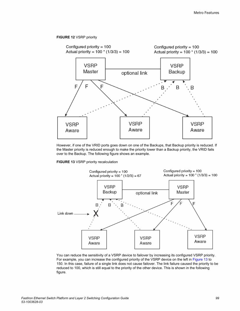
FIGURE 12 VSRP priority
However, if one of the VRID ports goes down on one of the Backups, that Backup priority is reduced. Ifthe Master priority is reduced enough to make the priority lower than a Backup priority, the VRID failsover to the Backup. The following figure shows an example.
FIGURE 13 VSRP priority recalculation
You can reduce the sensitivity of a VSRP device to failover by increasing its configured VSRP priority.For example, you can increase the configured priority of the VSRP device on the left in Figure 13 to150. In this case, failure of a single link does not cause failover. The link failure caused the priority to bereduced to 100, which is still equal to the priority of the other device. This is shown in the followingfigure.
Metro Features
FastIron Ethernet Switch Platform and Layer 2 Switching Configuration Guide 9953-1003628-03
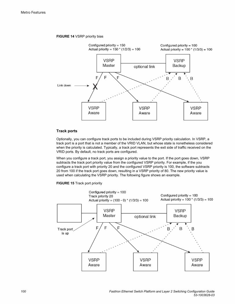
FIGURE 14 VSRP priority bias
Track ports
Optionally, you can configure track ports to be included during VSRP priority calculation. In VSRP, atrack port is a port that is not a member of the VRID VLAN, but whose state is nonetheless consideredwhen the priority is calculated. Typically, a track port represents the exit side of traffic received on theVRID ports. By default, no track ports are configured.
When you configure a track port, you assign a priority value to the port. If the port goes down, VSRPsubtracts the track port priority value from the configured VSRP priority. For example, if the youconfigure a track port with priority 20 and the configured VSRP priority is 100, the software subtracts20 from 100 if the track port goes down, resulting in a VSRP priority of 80. The new priority value isused when calculating the VSRP priority. The following figure shows an example.
FIGURE 15 Track port priority
Metro Features
100 FastIron Ethernet Switch Platform and Layer 2 Switching Configuration Guide53-1003628-03
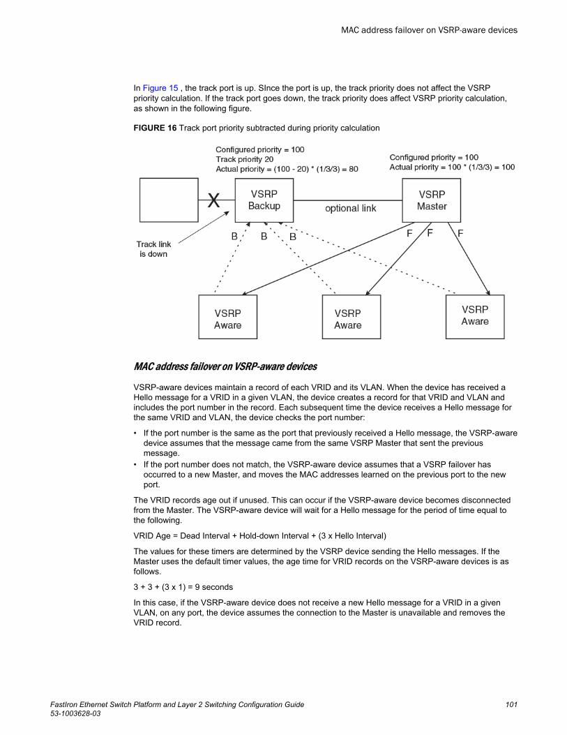
In Figure 15 , the track port is up. SInce the port is up, the track priority does not affect the VSRPpriority calculation. If the track port goes down, the track priority does affect VSRP priority calculation,as shown in the following figure.
FIGURE 16 Track port priority subtracted during priority calculation
MAC address failover on VSRP-aware devices
VSRP-aware devices maintain a record of each VRID and its VLAN. When the device has received aHello message for a VRID in a given VLAN, the device creates a record for that VRID and VLAN andincludes the port number in the record. Each subsequent time the device receives a Hello message forthe same VRID and VLAN, the device checks the port number:
• If the port number is the same as the port that previously received a Hello message, the VSRP-awaredevice assumes that the message came from the same VSRP Master that sent the previousmessage.
• If the port number does not match, the VSRP-aware device assumes that a VSRP failover hasoccurred to a new Master, and moves the MAC addresses learned on the previous port to the newport.
The VRID records age out if unused. This can occur if the VSRP-aware device becomes disconnectedfrom the Master. The VSRP-aware device will wait for a Hello message for the period of time equal tothe following.
VRID Age = Dead Interval + Hold-down Interval + (3 x Hello Interval)
The values for these timers are determined by the VSRP device sending the Hello messages. If theMaster uses the default timer values, the age time for VRID records on the VSRP-aware devices is asfollows.
3 + 3 + (3 x 1) = 9 seconds
In this case, if the VSRP-aware device does not receive a new Hello message for a VRID in a givenVLAN, on any port, the device assumes the connection to the Master is unavailable and removes theVRID record.
MAC address failover on VSRP-aware devices
FastIron Ethernet Switch Platform and Layer 2 Switching Configuration Guide 10153-1003628-03
VSRP interval timers
The VSRP Hello interval, Dead interval, Backup Hello interval, and Hold-down interval timers areindividually configurable. You also can easily change all the timers at the same time while preservingthe ratios among their values. To do so, change the timer scale. The timer scale is a value used by thesoftware to calculate the timers. The software divides a timer value by the timer scale value. Bydefault, the scale is 1. This means the VSRP timer values are the same as the values in theconfiguration.
VSRP-aware security featuresThis feature protects against unauthorized VSRP hello packets by enabling you to configure VSRP-aware security parameters. Without VSRP-aware security, a VSRP-aware device passively learns theauthentication method conveyed by the received VSRP hello packet. The VSRP-aware device thenstores the authentication method until it ages out with the aware entry.
The VSRP-aware security feature enables you to perform the following:
• Define the specific authentication parameters that a VSRP-aware device will use on a VSRPbackup switch. The authentication parameters that you define will not age out.
• Define a list of ports that have authentic VSRP backup switch connections. For ports included in thelist, the VSRP-aware switch will process VSRP hello packets using the VSRP-aware securityconfiguration. Conversely, for ports not included in the list, the VSRP-aware switch will not use theVSRP-aware security configuration.
If VSRP hello packets do not meet the acceptance criteria, the VSRP-aware device forwards thepackets normally, without any VSRP-aware security processing.
To configure VSRP-Aware Security features, refer to Configuring security features on a VSRP-awaredevice on page 108.
VSRP parametersThe following table lists the VSRP parameters.
VSRP parameters TABLE 22
Parameter Description Default For moreinformation
Protocol VSRP state
NOTEOn a Layer 3 Switch, you must disable VSRP touse VRRP-E or VRRP.
Enabled Disabling or re-enabling VSRP onpage 106
Virtual Router ID(VRID)
The ID of the virtual switch you are creating byconfiguring multiple devices as redundant links.You must configure the same VRID on eachdevice that you want to use to back up the links.
None Configuring basicVSRP parameters onpage 106
VSRP interval timers
102 FastIron Ethernet Switch Platform and Layer 2 Switching Configuration Guide53-1003628-03
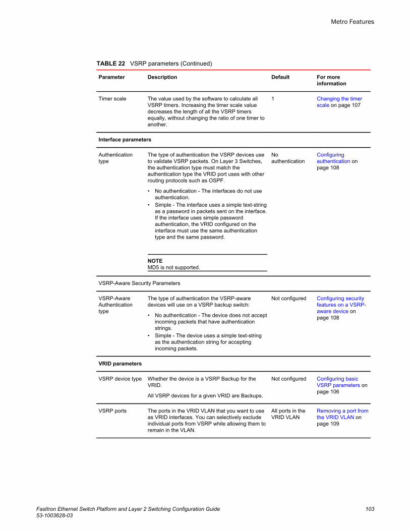
VSRP parameters (Continued)TABLE 22
Parameter Description Default For moreinformation
Timer scale The value used by the software to calculate allVSRP timers. Increasing the timer scale valuedecreases the length of all the VSRP timersequally, without changing the ratio of one timer toanother.
1 Changing the timerscale on page 107
Interface parameters
Authenticationtype
The type of authentication the VSRP devices useto validate VSRP packets. On Layer 3 Switches,the authentication type must match theauthentication type the VRID port uses with otherrouting protocols such as OSPF.
• No authentication - The interfaces do not useauthentication.
• Simple - The interface uses a simple text-stringas a password in packets sent on the interface.If the interface uses simple passwordauthentication, the VRID configured on theinterface must use the same authenticationtype and the same password.
NOTEMD5 is not supported.
Noauthentication
Configuringauthentication onpage 108
VSRP-Aware Security Parameters
VSRP-AwareAuthenticationtype
The type of authentication the VSRP-awaredevices will use on a VSRP backup switch:
• No authentication - The device does not acceptincoming packets that have authenticationstrings.
• Simple - The device uses a simple text-stringas the authentication string for acceptingincoming packets.
Not configured Configuring securityfeatures on a VSRP-aware device onpage 108
VRID parameters
VSRP device type Whether the device is a VSRP Backup for theVRID.
All VSRP devices for a given VRID are Backups.
Not configured Configuring basicVSRP parameters onpage 106
VSRP ports The ports in the VRID VLAN that you want to useas VRID interfaces. You can selectively excludeindividual ports from VSRP while allowing them toremain in the VLAN.
All ports in theVRID VLAN
Removing a port fromthe VRID VLAN onpage 109
Metro Features
FastIron Ethernet Switch Platform and Layer 2 Switching Configuration Guide 10353-1003628-03
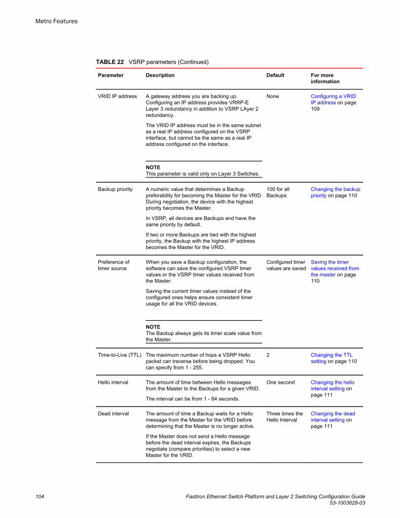
VSRP parameters (Continued)TABLE 22
Parameter Description Default For moreinformation
VRID IP address A gateway address you are backing up.Configuring an IP address provides VRRP-ELayer 3 redundancy in addition to VSRP LAyer 2redundancy.
The VRID IP address must be in the same subnetas a real IP address configured on the VSRPinterface, but cannot be the same as a real IPaddress configured on the interface.
NOTEThis parameter is valid only on Layer 3 Switches.
None Configuring a VRIDIP address on page109
Backup priority A numeric value that determines a Backuppreferability for becoming the Master for the VRID.During negotiation, the device with the highestpriority becomes the Master.
In VSRP, all devices are Backups and have thesame priority by default.
If two or more Backups are tied with the highestpriority, the Backup with the highest IP addressbecomes the Master for the VRID.
100 for allBackups
Changing the backuppriority on page 110
Preference oftimer source
When you save a Backup configuration, thesoftware can save the configured VSRP timervalues or the VSRP timer values received fromthe Master.
Saving the current timer values instead of theconfigured ones helps ensure consistent timerusage for all the VRID devices.
NOTEThe Backup always gets its timer scale value fromthe Master.
Configured timervalues are saved
Saving the timervalues received fromthe master on page110
Time-to-Live (TTL) The maximum number of hops a VSRP Hellopacket can traverse before being dropped. Youcan specify from 1 - 255.
2 Changing the TTLsetting on page 110
Hello interval The amount of time between Hello messagesfrom the Master to the Backups for a given VRID.
The interval can be from 1 - 84 seconds.
One second Changing the hellointerval setting onpage 111
Dead interval The amount of time a Backup waits for a Hellomessage from the Master for the VRID beforedetermining that the Master is no longer active.
If the Master does not send a Hello messagebefore the dead interval expires, the Backupsnegotiate (compare priorities) to select a newMaster for the VRID.
Three times theHello Interval
Changing the deadinterval setting onpage 111
Metro Features
104 FastIron Ethernet Switch Platform and Layer 2 Switching Configuration Guide53-1003628-03
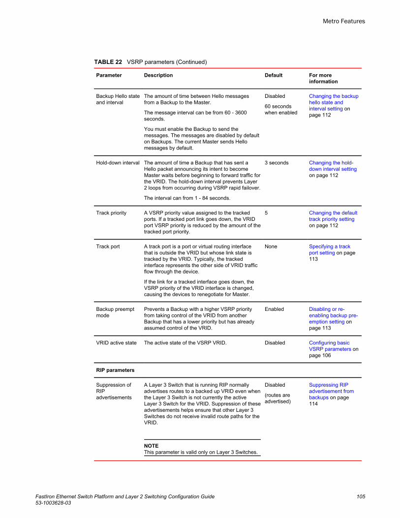
VSRP parameters (Continued)TABLE 22
Parameter Description Default For moreinformation
Backup Hello stateand interval
The amount of time between Hello messagesfrom a Backup to the Master.
The message interval can be from 60 - 3600seconds.
You must enable the Backup to send themessages. The messages are disabled by defaulton Backups. The current Master sends Hellomessages by default.
Disabled
60 secondswhen enabled
Changing the backuphello state andinterval setting onpage 112
Hold-down interval The amount of time a Backup that has sent aHello packet announcing its intent to becomeMaster waits before beginning to forward traffic forthe VRID. The hold-down interval prevents Layer2 loops from occurring during VSRP rapid failover.
The interval can from 1 - 84 seconds.
3 seconds Changing the hold-down interval settingon page 112
Track priority A VSRP priority value assigned to the trackedports. If a tracked port link goes down, the VRIDport VSRP priority is reduced by the amount of thetracked port priority.
5 Changing the defaulttrack priority settingon page 112
Track port A track port is a port or virtual routing interfacethat is outside the VRID but whose link state istracked by the VRID. Typically, the trackedinterface represents the other side of VRID trafficflow through the device.
If the link for a tracked interface goes down, theVSRP priority of the VRID interface is changed,causing the devices to renegotiate for Master.
None Specifying a trackport setting on page113
Backup preemptmode
Prevents a Backup with a higher VSRP priorityfrom taking control of the VRID from anotherBackup that has a lower priority but has alreadyassumed control of the VRID.
Enabled Disabling or re-enabling backup pre-emption setting onpage 113
VRID active state The active state of the VSRP VRID. Disabled Configuring basicVSRP parameters onpage 106
RIP parameters
Suppression ofRIPadvertisements
A Layer 3 Switch that is running RIP normallyadvertises routes to a backed up VRID even whenthe Layer 3 Switch is not currently the activeLayer 3 Switch for the VRID. Suppression of theseadvertisements helps ensure that other Layer 3Switches do not receive invalid route paths for theVRID.
NOTEThis parameter is valid only on Layer 3 Switches.
Disabled
(routes areadvertised)
Suppressing RIPadvertisement frombackups on page114
Metro Features
FastIron Ethernet Switch Platform and Layer 2 Switching Configuration Guide 10553-1003628-03
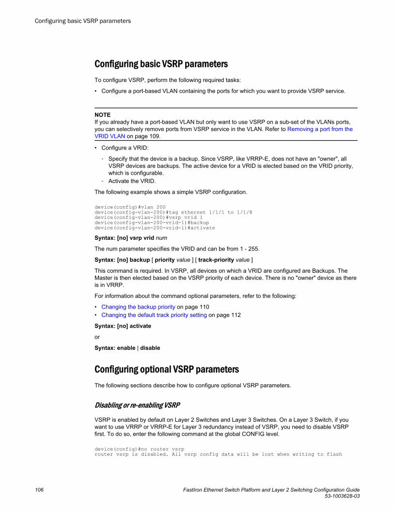
Configuring basic VSRP parametersTo configure VSRP, perform the following required tasks:
• Configure a port-based VLAN containing the ports for which you want to provide VSRP service.
NOTEIf you already have a port-based VLAN but only want to use VSRP on a sub-set of the VLANs ports,you can selectively remove ports from VSRP service in the VLAN. Refer to Removing a port from theVRID VLAN on page 109.
• Configure a VRID:
‐ Specify that the device is a backup. Since VSRP, like VRRP-E, does not have an "owner", allVSRP devices are backups. The active device for a VRID is elected based on the VRID priority,which is configurable.
‐ Activate the VRID.
The following example shows a simple VSRP configuration.
device(config)#vlan 200device(config-vlan-200)#tag ethernet 1/1/1 to 1/1/8device(config-vlan-200)#vsrp vrid 1device(config-vlan-200-vrid-1)#backupdevice(config-vlan-200-vrid-1)#activateSyntax: [no] vsrp vrid num
The num parameter specifies the VRID and can be from 1 - 255.
Syntax: [no] backup [ priority value ] [ track-priority value ]
This command is required. In VSRP, all devices on which a VRID are configured are Backups. TheMaster is then elected based on the VSRP priority of each device. There is no "owner" device as thereis in VRRP.
For information about the command optional parameters, refer to the following:
• Changing the backup priority on page 110• Changing the default track priority setting on page 112
Syntax: [no] activate
or
Syntax: enable | disable
Configuring optional VSRP parametersThe following sections describe how to configure optional VSRP parameters.
Disabling or re-enabling VSRP
VSRP is enabled by default on Layer 2 Switches and Layer 3 Switches. On a Layer 3 Switch, if youwant to use VRRP or VRRP-E for Layer 3 redundancy instead of VSRP, you need to disable VSRPfirst. To do so, enter the following command at the global CONFIG level.
device(config)#no router vsrprouter vsrp is disabled. All vsrp config data will be lost when writing to flash
Configuring basic VSRP parameters
106 FastIron Ethernet Switch Platform and Layer 2 Switching Configuration Guide53-1003628-03
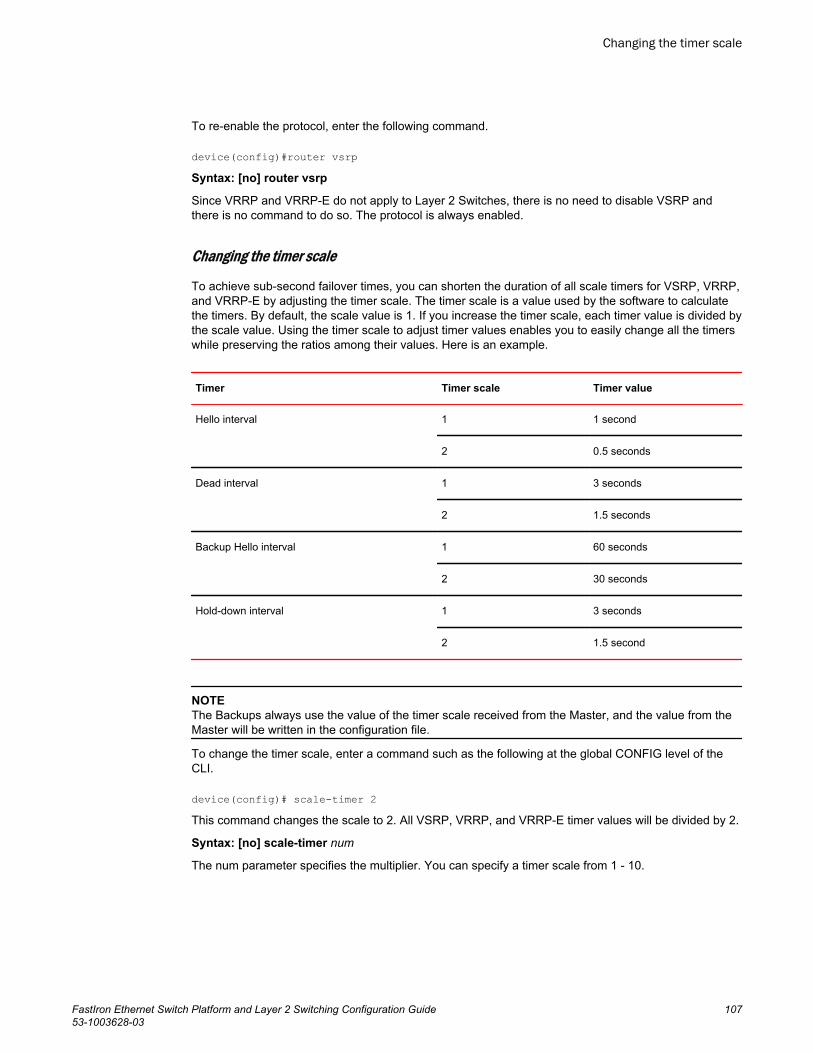
To re-enable the protocol, enter the following command.
device(config)#router vsrpSyntax: [no] router vsrp
Since VRRP and VRRP-E do not apply to Layer 2 Switches, there is no need to disable VSRP andthere is no command to do so. The protocol is always enabled.
Changing the timer scale
To achieve sub-second failover times, you can shorten the duration of all scale timers for VSRP, VRRP,and VRRP-E by adjusting the timer scale. The timer scale is a value used by the software to calculatethe timers. By default, the scale value is 1. If you increase the timer scale, each timer value is divided bythe scale value. Using the timer scale to adjust timer values enables you to easily change all the timerswhile preserving the ratios among their values. Here is an example.
Timer Timer scale Timer value
Hello interval 1 1 second
2 0.5 seconds
Dead interval 1 3 seconds
2 1.5 seconds
Backup Hello interval 1 60 seconds
2 30 seconds
Hold-down interval 1 3 seconds
2 1.5 second
NOTEThe Backups always use the value of the timer scale received from the Master, and the value from theMaster will be written in the configuration file.
To change the timer scale, enter a command such as the following at the global CONFIG level of theCLI.
device(config)# scale-timer 2This command changes the scale to 2. All VSRP, VRRP, and VRRP-E timer values will be divided by 2.
Syntax: [no] scale-timer num
The num parameter specifies the multiplier. You can specify a timer scale from 1 - 10.
Changing the timer scale
FastIron Ethernet Switch Platform and Layer 2 Switching Configuration Guide 10753-1003628-03
Configuring authentication
If the interfaces on which you configure the VRID use authentication, the VSRP packets on thoseinterfaces also must use the same authentication. VSRP supports the following authentication types:
• No authentication - The interfaces do not use authentication.• Simple - The interfaces use a simple text-string as a password in packets sent on the interface. If
the interfaces use simple password authentication, the VRID configured on the interfaces must usethe same authentication type and the same password.
To configure a simple password, enter a command such as the following at the VLAN configurationlevel.
device(config-vlan-10)#vsrp auth-type simple-text-auth ourpword This command configures the simple text password "ourpword".
Syntax: [no] vsrp auth-type { no-auth | simple-text-auth auth-data }
The auth-type no-auth parameter indicates that the VRID and the interface it is configured on do notuse authentication.
The auth-type simple-text-auth auth-data parameter indicates that the VRID and the interface it isconfigured on use a simple text password for authentication. The auth-data value is the password, andcan be up to eight characters. If you use this parameter, make sure all interfaces on all the devicessupporting this VRID are configured for simple password authentication and use the same password.
Configuring security features on a VSRP-aware device
This section shows how to configure security features on a VSRP-aware device. For an overview ofthis feature, refer to VSRP-aware security features on page 102.
Specifying an authentication string for VSRP hello packets
The following configuration defines pri-key as the authentication string for accepting incoming VSRPhello packets. In this example, the VSRP-aware device will accept all incoming packets that have thisauthorization string.
device(config)#vlan 10device(config-vlan-10)#vsrp-aware vrid 3 simple-text-auth pri-keySyntax: vsrp-aware vrid vridnumber simple-text-auth string
Specifying no authentication for VSRP hello packets
The following configuration specifies no authentication as the preferred VSRP-aware security method.In this case, the VSRP device will not accept incoming packets that have authentication strings.
device(config)#vlan 10device(config-vlan-10)#vsrp-aware vrid 2 no-authSyntax: vsrp-aware vrid vridnumber no-auth
The following configuration specifies no authentication for VSRP hello packets received on ports 1/1/1,1/1/2, 1/1/3, and 1/1/4 in VRID 4. For these ports, the VSRP device will not accept incoming packetsthat have authentication strings.
device(config)#vlan 10device(config-vlan-10)#vsrp-aware vrid 4 no-auth port-list ethernet 1/1/1 to 1/1/4
Configuring authentication
108 FastIron Ethernet Switch Platform and Layer 2 Switching Configuration Guide53-1003628-03
Syntax: [no] vsrp-aware vrid vridnumber no-auth port-list portrange
vrid number is a valid VRID (from 1 to 255).
no-auth specifies no authentication as the preferred VSRP-aware security method. The VSRP devicewill not accept incoming packets that have authentication strings.
simple-text-auth string specifies the authentication string for accepting VSRP hello packets, wherestring can be up to 8 characters.
port-list port range specifies the range of ports to include in the configuration.
Removing a port from the VRID VLAN
By default, all the ports on which you configure a VRID are interfaces for the VRID. You can remove aport from the VRID while allowing it to remain in the VLAN.
Removing a port is useful in the following cases:
• There is no risk of a loop occurring, such as when the port is attached directly to an end host.• You plan to use a port in an MRP ring.
To remove a port from a VRID, enter a command such as the following at the configuration level for theVRID.
device(config-vlan-200-vrid-1)#no include-port ethernet 1/1/2Syntax: [no] include-port ethernet unit /slotnum/portnum
The slotnum parameter is required on chassis devices.
The portnum parameter specifies the port you are removing from the VRID. The port remains in theVLAN but its forwarding state is not controlled by VSRP. If you are configuring a chassis device, specifythe slot number as well as the port number (unit/slotnum/portnum).
Configuring a VRID IP address
If you are configuring a Layer 3 Switch for VSRP, you can specify an IP address to back up. When youspecify an IP address, VSRP provides redundancy for the address. This is useful if you want to back upthe gateway address used by hosts attached to the VSRP Backups.
VSRP does not require you to specify an IP address. If you do not specify an address, VSRP providesLayer 2 redundancy. If you do specify an address, VSRP provides Layer 2 and Layer 3 redundancy.
The Layer 3 redundancy support is the same as VRRP-E support. For information, refer to the FastIronEthernet Switch Layer 3 Routing Configuration Guide .
NOTEThe VRID IP address must be in the same subnet as a real IP address configured on the VSRPinterface, but cannot be the same as a real IP address configured on the interface.
NOTEFailover applies to both Layer 2 and Layer 3.
To specify an IP address to back up, enter a command such as the following at the configuration levelfor the VRID.
device(config-vlan-200-vrid-1)#ip-address 10.10.10.1
Removing a port from the VRID VLAN
FastIron Ethernet Switch Platform and Layer 2 Switching Configuration Guide 10953-1003628-03
Syntax: [no] ip-address ip-addr
Changing the backup priority
When you enter the backup command to configure the device as a VSRP Backup for the VRID, youalso can change the backup priority and the track priority:
• The backup priority is used for election of the Master. The VSRP Backup with the highest priorityvalue for the VRID is elected as the Master for that VRID. The default priority is 100. If two or moreBackups are tied with the highest priority, the Backup with the highest IP address becomes theMaster for the VRID.
• The track priority is used with the track port feature. Refer to VSRP priority calculation on page 98and Changing the default track priority setting on page 112.
To change the backup priority, enter a command such as the following at the configuration level for theVRID.
device(config-vlan-200-vrid-1)#backup priority 75Syntax: [no] backup [ priority value ] [ track-priority value ]
The priority value parameter specifies the backup priority for this interface and VRID. Specify a valueas follows:
• For VRRP, specify a value from 3 - 254. The default is 100.• For VSRP and VRRP-E, specify a value from 6 - 255. The default is 100.
For a description of the track-priority value parameter, refer to Changing the default track prioritysetting on page 112.
Saving the timer values received from the master
The Hello messages sent by a VRID master contain the VRID values for the following VSRP timers:
• Hello interval• Dead interval• Backup Hello interval• Hold-down interval
The Backups always use the value of the timers received from the Master.
To configure a Backup to save the VSRP timer values received from the Master instead of the timervalues configured on the Backup, enter the following command. Saving the current timer valuesinstead of the configured ones helps ensure consistent timer usage for all the VRID devices.
device(config-vlan-200-vrid-1)#save-current-valuesSyntax: [no] save-current-values
Changing the TTL setting
A VSRP Hello packet time to live (TTL) specifies how many hops the packet can traverse before beingdropped. A hop can be a Layer 3 Switch or a Layer 2 Switch. You can specify from 1 - 255. Thedefault TTL is 2. When a VSRP device (Master or Backup) sends a VSRP HEllo packet, the devicesubtracts one from the TTL. Thus, if the TTL is 2, the device that originates the Hello packet sends itout with a TTL of 1. Each subsequent device that receives the packet also subtracts one from thepacket TTL. When the packet has a TTL of 1, the receiving device subtracts 1 and then drops thepacket because the TTL is zero.
Changing the backup priority
110 FastIron Ethernet Switch Platform and Layer 2 Switching Configuration Guide53-1003628-03
NOTEAn MRP ring is considered to be a single hop, regardless of the number of nodes in the ring.
To change the TTL for a VRID, enter a command such as the following at the configuration level for theVRID.
device(config-vlan-200-vrid-1)#initial-ttl 5Syntax: [no] initial-ttl num
The num parameter specifies the TTL and can be from 1 - 255. The default TTL is 2.
Changing the hello interval setting
The Master periodically sends Hello messages to the Backups. To change the Hello interval, enter acommand such as the following at the configuration level for the VRID.
device(config-vlan-200-vrid-1)#hello-interval 10Syntax: [no] hello-interval num
The num parameter specifies the interval and can be from 1 - 84 seconds. The default is 1 second.
NOTEThe default Dead interval is three times the Hello interval plus one-half second. Generally, if you changethe Hello interval, you also should change the Dead interval on the Backups.
NOTEIf you change the timer scale, the change affects the actual number of seconds.
Changing the dead interval setting
The Dead interval is the number of seconds a Backup waits for a Hello message from the Master beforedetermining that the Master is dead. The default is 3 seconds. This is three times the default Hellointerval.
To change the Dead interval, enter a command such as the following at the configuration level for theVRID.
device(config-vlan-200-vrid-1)#dead-interval 30Syntax: [no] dead-interval num
The num parameter specifies the interval and can be from 1 - 84 seconds. The default is 3 seconds.
NOTEIf you change the timer scale, the change affects the actual number of seconds.
Changing the hello interval setting
FastIron Ethernet Switch Platform and Layer 2 Switching Configuration Guide 11153-1003628-03
Changing the backup hello state and interval setting
By default, Backups do not send Hello messages to advertise themselves to the Master. You canenable these messages if desired and also change the message interval.
To enable a Backup to send Hello messages to the Master, enter a command such as the following atthe configuration level for the VRID.
device(config-vlan-200-vrid-1)#advertise backupSyntax: [no] advertise backup
When a Backup is enabled to send Hello messages, the Backup sends a Hello message to the Masterevery 60 seconds by default. You can change the interval to be up to 3600 seconds.
To change the Backup Hello interval, enter a command such as the following at the configuration levelfor the VRID.
device(config-vlan-200-vrid-1)#backup-hello-interval 180Syntax: [no] backup-hello-interval num
The num parameter specifies the message interval and can be from 60 - 3600 seconds. The default is60 seconds.
NOTEIf you change the timer scale, the change affects the actual number of seconds.
Changing the hold-down interval setting
The hold-down interval prevents Layer 2 loops from occurring during failover, by delaying the newMaster from forwarding traffic long enough to ensure that the failed Master is really unavailable.
To change the Hold-down interval, enter a command such as the following at the configuration levelfor the VRID.
device(config-vlan-200-vrid-1)#hold-down-interval 4Syntax: [no] hold-down-intervalnum
The num parameter specifies the hold-down interval and can be from 1 - 84 seconds. The default is 3seconds.
NOTEIf you change the timer scale, the change affects the actual number of seconds.
Changing the default track priority setting
When you configure a VRID to track the link state of other interfaces, if one of the tracked interfacegoes down, the software changes the VSRP priority of the VRID interface.
The software reduces the VRID priority by the amount of the priority of the tracked interface that wentdown. For example, if the VSRP interface priority is 100 and a tracked interface with track priority 60goes down, the software changes the VSRP interface priority to 40. If another tracked interface goesdown, the software reduces the VRID priority again, by the amount of the tracked interface trackpriority.
Changing the backup hello state and interval setting
112 FastIron Ethernet Switch Platform and Layer 2 Switching Configuration Guide53-1003628-03
The default track priority for all track ports is 5. You can change the default track priority or override thedefault for an individual track port.
• To change the default track priority, use the backup priority value track-priority value command,described below.
• To override the default track priority for a specific track port, use the track-port command. Refer to Specifying a track port setting on page 113.
To change the track priority, enter a command such as the following at the configuration level for theVRID.
device(config-vlan-200-vrid-1)#backup priority 100 track-priority 2Syntax: [no] backup [ priority value ] [ track-priority value ]
Specifying a track port setting
You can configure the VRID on one interface to track the link state of another interface on the device.This capability is useful for tracking the state of the exit interface for the path for which the VRID isproviding redundancy. Refer to VSRP priority calculation on page 98.
To configure a VRID to track an interface, enter a command such as the following at the configurationlevel for the VRID.
device(config-vlan-200-vrid-1)#track-port ethernet 1/2/4Syntax: [no] track-port ethernet unit/slotnum/portnum | ve num [ priority num ]
The priority num parameter changes the VSRP priority of the interface. If this interface goes down, theVRID VSRP priority is reduced by the amount of the track port priority you specify here.
NOTEThe priority num option changes the priority of the specified interface, overriding the default track portpriority. To change the default track port priority, use the backup track-priority num command.
Disabling or re-enabling backup pre-emption setting
By default, a Backup that has a higher priority than another Backup that has become the Master canpreempt the Master, and take over the role of Master. If you want to prevent this behavior, disablepreemption.
Preemption applies only to Backups and takes effect only when the Master has failed and a Backup hasassumed ownership of the VRID. The feature prevents a Backup with a higher priority from taking overas Master from another Backup that has a lower priority but has already become the Master of theVRID.
Preemption is especially useful for preventing flapping in situations where there are multiple Backupsand a Backup with a lower priority than another Backup has assumed ownership, because the Backupwith the higher priority was unavailable when ownership changed.
If you enable the non-preempt mode (thus disabling the preemption feature) on all the Backups, theBackup that becomes the Master following the disappearance of the Master continues to be the Master.The new Master is not preempted.
To disable preemption on a Backup, enter a command such as the following at the configuration levelfor the VRID.
device(config-vlan-200-vrid-1)#non-preempt-mode
Specifying a track port setting
FastIron Ethernet Switch Platform and Layer 2 Switching Configuration Guide 11353-1003628-03
Syntax: [no] non-preempt-mode
Suppressing RIP advertisement from backups
Normally, for Layer 3 a VSRP Backup includes route information for a backed up IP address in RIPadvertisements. As a result, other Layer 3 Switches receive multiple paths for the backed up interfaceand might sometimes unsuccessfully use the path to the Backup rather than the path to the Master.
You can prevent the Backups from advertising route information for the backed up interface byenabling suppression of the advertisements.
NOTEThis parameter applies only if you specified an IP address to back up and is valid only on Layer 3Switches.
To suppress RIP advertisements, enter the following commands.
device(config)#router ripdevice(config-rip-router)#use-vrrp-pathSyntax: [no] use-vrrp-path
VSRP-aware interoperablilty
The vsrp-aware tc-vlan-flush command should be used in network configurations in which theBrocade switch operates as the VSRP-Aware device connecting to a FastIron platforms configured asa VSRP Master.
The command is available at the VLAN level, and is issued per a specific VRID, as shown here forVRID 11.
device(config-vlan-10)#vsrp-aware vrid 11 tc-vlan-flushSyntax: vsrp-aware vrid num tc-vlan-flush
When this command is enabled, MAC addresses will be flushed at the VLAN level, instead of at theport level. MAC addresses will be flushed for every topology change (TC) received on the VSRP-aware ports.
When you configure the vsrp-aware tc-vlan-flush command on a VSRP-aware device, and thedevice receives VSRP hello packets from the VSRP master, VSRP authentication is automaticallyconfigured. However, if the VSRP-aware device does not receive VSRP hello packets from the VSRPmaster when the vsrp-aware tc-vlan-flush command is configured, you must manually configureVSRP authentication. For more information on configuring VSRP authentication, refer to Configuringauthentication on page 108.
When this command is enabled, the results of the show vsrp-aware vlan command resemble thefollowing.
device(config-vlan-10)#vsrp-aware vrid 11 tc-vlan-flushdevice(config-vlan-10)#show vsrp aware vlan 10Aware Port Listing VLAN ID VRID Last Port Auth Type Mac-Flush Age 10 11 N/A no-auth Configured Enabled 00:00:00.0
Suppressing RIP advertisement from backups
114 FastIron Ethernet Switch Platform and Layer 2 Switching Configuration Guide53-1003628-03
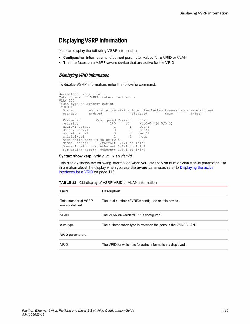
Displaying VSRP informationYou can display the following VSRP information:
• Configuration information and current parameter values for a VRID or VLAN• The interfaces on a VSRP-aware device that are active for the VRID
Displaying VRID information
To display VSRP information, enter the following command.
device#show vsrp vrid 1Total number of VSRP routers defined: 2VLAN 200 auth-type no authentication VRID 1 State Administrative-status Advertise-backup Preempt-mode save-current standby enabled disabled true false Parameter Configured Current Unit priority 100 80 (100-0)*(4.0/5.0) hello-interval 1 1 sec/1 dead-interval 3 3 sec/1 hold-interval 3 3 sec/1 initial-ttl 2 2 hops next hello sent in 00:00:00.8 Member ports: ethernet 1/1/1 to 1/1/5 Operational ports: ethernet 1/1/1 to 1/1/4 Forwarding ports: ethernet 1/1/1 to 1/1/4Syntax: show vsrp [ vrid num | vlan vlan-id ]
This display shows the following information when you use the vrid num or vlan vlan-id parameter. Forinformation about the display when you use the aware parameter, refer to Displaying the activeinterfaces for a VRID on page 118.
CLI display of VSRP VRID or VLAN information TABLE 23
Field Description
Total number of VSRProuters defined
The total number of VRIDs configured on this device.
VLAN The VLAN on which VSRP is configured.
auth-type The authentication type in effect on the ports in the VSRP VLAN.
VRID parameters
VRID The VRID for which the following information is displayed.
Displaying VSRP information
FastIron Ethernet Switch Platform and Layer 2 Switching Configuration Guide 11553-1003628-03
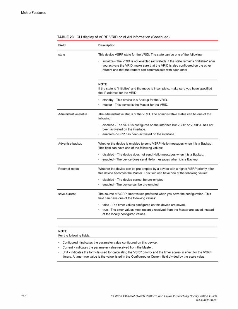
CLI display of VSRP VRID or VLAN information (Continued)TABLE 23
Field Description
state This device VSRP state for the VRID. The state can be one of the following:
• initialize - The VRID is not enabled (activated). If the state remains "initialize" afteryou activate the VRID, make sure that the VRID is also configured on the otherrouters and that the routers can communicate with each other.
NOTEIf the state is "initialize" and the mode is incomplete, make sure you have specifiedthe IP address for the VRID.
• standby - This device is a Backup for the VRID.• master - This device is the Master for the VRID.
Administrative-status The administrative status of the VRID. The administrative status can be one of thefollowing:
• disabled - The VRID is configured on the interface but VSRP or VRRP-E has notbeen activated on the interface.
• enabled - VSRP has been activated on the interface.
Advertise-backup Whether the device is enabled to send VSRP Hello messages when it is a Backup.This field can have one of the following values:
• disabled - The device does not send Hello messages when it is a Backup.• enabled - The device does send Hello messages when it is a Backup.
Preempt-mode Whether the device can be pre-empted by a device with a higher VSRP priority afterthis device becomes the Master. This field can have one of the following values:
• disabled - The device cannot be pre-empted.• enabled - The device can be pre-empted.
save-current The source of VSRP timer values preferred when you save the configuration. Thisfield can have one of the following values:
• false - The timer values configured on this device are saved.• true - The timer values most recently received from the Master are saved instead
of the locally configured values.
NOTEFor the following fields:
• Configured - indicates the parameter value configured on this device.• Current - indicates the parameter value received from the Master.• Unit - indicates the formula used tor calculating the VSRP priority and the timer scales in effect for the VSRP
timers. A timer true value is the value listed in the Configured or Current field divided by the scale value.
Metro Features
116 FastIron Ethernet Switch Platform and Layer 2 Switching Configuration Guide53-1003628-03
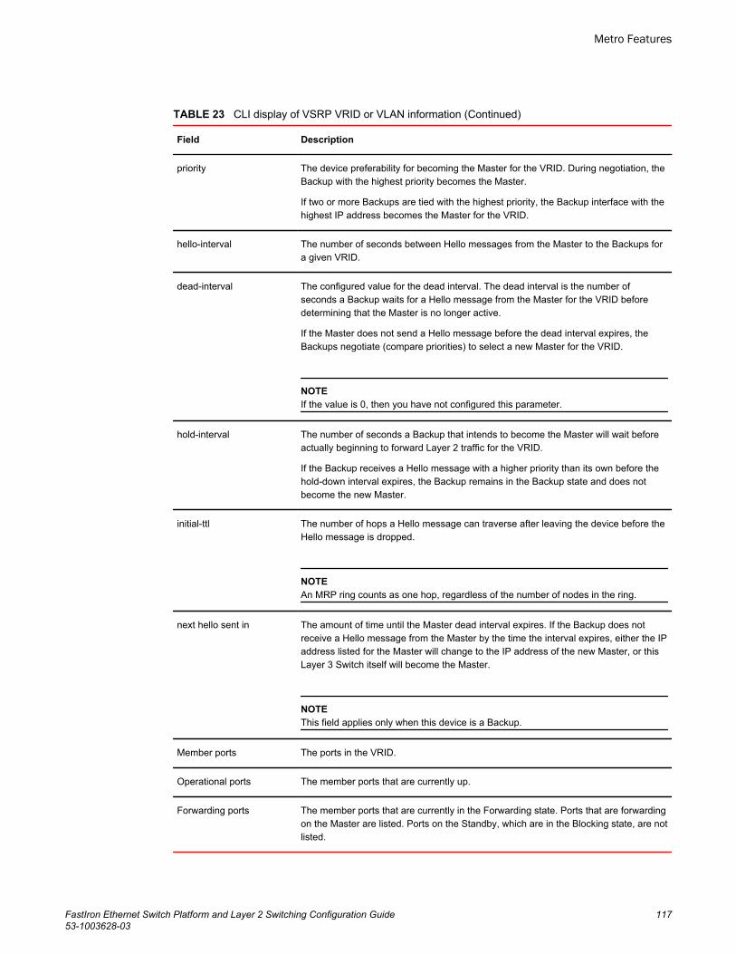
CLI display of VSRP VRID or VLAN information (Continued)TABLE 23
Field Description
priority The device preferability for becoming the Master for the VRID. During negotiation, theBackup with the highest priority becomes the Master.
If two or more Backups are tied with the highest priority, the Backup interface with thehighest IP address becomes the Master for the VRID.
hello-interval The number of seconds between Hello messages from the Master to the Backups fora given VRID.
dead-interval The configured value for the dead interval. The dead interval is the number ofseconds a Backup waits for a Hello message from the Master for the VRID beforedetermining that the Master is no longer active.
If the Master does not send a Hello message before the dead interval expires, theBackups negotiate (compare priorities) to select a new Master for the VRID.
NOTEIf the value is 0, then you have not configured this parameter.
hold-interval The number of seconds a Backup that intends to become the Master will wait beforeactually beginning to forward Layer 2 traffic for the VRID.
If the Backup receives a Hello message with a higher priority than its own before thehold-down interval expires, the Backup remains in the Backup state and does notbecome the new Master.
initial-ttl The number of hops a Hello message can traverse after leaving the device before theHello message is dropped.
NOTEAn MRP ring counts as one hop, regardless of the number of nodes in the ring.
next hello sent in The amount of time until the Master dead interval expires. If the Backup does notreceive a Hello message from the Master by the time the interval expires, either the IPaddress listed for the Master will change to the IP address of the new Master, or thisLayer 3 Switch itself will become the Master.
NOTEThis field applies only when this device is a Backup.
Member ports The ports in the VRID.
Operational ports The member ports that are currently up.
Forwarding ports The member ports that are currently in the Forwarding state. Ports that are forwardingon the Master are listed. Ports on the Standby, which are in the Blocking state, are notlisted.
Metro Features
FastIron Ethernet Switch Platform and Layer 2 Switching Configuration Guide 11753-1003628-03
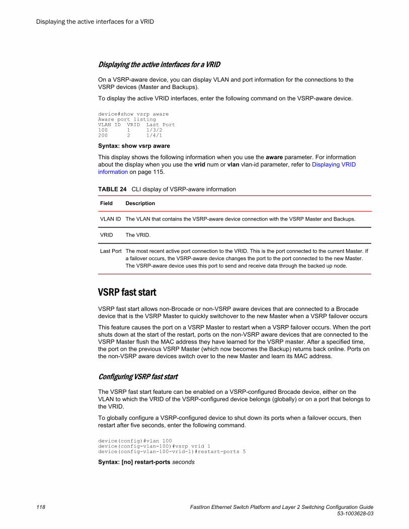
Displaying the active interfaces for a VRID
On a VSRP-aware device, you can display VLAN and port information for the connections to theVSRP devices (Master and Backups).
To display the active VRID interfaces, enter the following command on the VSRP-aware device.
device#show vsrp awareAware port listingVLAN ID VRID Last Port100 1 1/3/2200 2 1/4/1Syntax: show vsrp aware
This display shows the following information when you use the aware parameter. For informationabout the display when you use the vrid num or vlan vlan-id parameter, refer to Displaying VRIDinformation on page 115.
CLI display of VSRP-aware information TABLE 24
Field Description
VLAN ID The VLAN that contains the VSRP-aware device connection with the VSRP Master and Backups.
VRID The VRID.
Last Port The most recent active port connection to the VRID. This is the port connected to the current Master. Ifa failover occurs, the VSRP-aware device changes the port to the port connected to the new Master.The VSRP-aware device uses this port to send and receive data through the backed up node.
VSRP fast startVSRP fast start allows non-Brocade or non-VSRP aware devices that are connected to a Brocadedevice that is the VSRP Master to quickly switchover to the new Master when a VSRP failover occurs
This feature causes the port on a VSRP Master to restart when a VSRP failover occurs. When the portshuts down at the start of the restart, ports on the non-VSRP aware devices that are connected to theVSRP Master flush the MAC address they have learned for the VSRP master. After a specified time,the port on the previous VSRP Master (which now becomes the Backup) returns back online. Ports onthe non-VSRP aware devices switch over to the new Master and learn its MAC address.
Configuring VSRP fast start
The VSRP fast start feature can be enabled on a VSRP-configured Brocade device, either on theVLAN to which the VRID of the VSRP-configured device belongs (globally) or on a port that belongs tothe VRID.
To globally configure a VSRP-configured device to shut down its ports when a failover occurs, thenrestart after five seconds, enter the following command.
device(config)#vlan 100device(config-vlan-100)#vsrp vrid 1device(config-vlan-100-vrid-1)#restart-ports 5Syntax: [no] restart-ports seconds
Displaying the active interfaces for a VRID
118 FastIron Ethernet Switch Platform and Layer 2 Switching Configuration Guide53-1003628-03
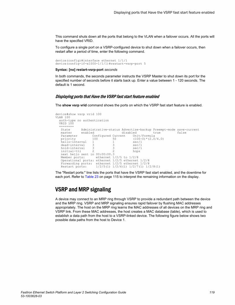
This command shuts down all the ports that belong to the VLAN when a failover occurs. All the ports willhave the specified VRID.
To configure a single port on a VSRP-configured device to shut down when a failover occurs, thenrestart after a period of time, enter the following command.
device(config)#interface ethernet 1/1/1device(config-if-e1000-1/1/1)#restart-vsrp-port 5Syntax: [no] restart-vsrp-port seconds
In both commands, the seconds parameter instructs the VSRP Master to shut down its port for thespecified number of seconds before it starts back up. Enter a value between 1 - 120 seconds. Thedefault is 1 second.
Displaying ports that Have the VSRP fast start feature enabled
The show vsrp vrid command shows the ports on which the VSRP fast start feature is enabled.
device#show vsrp vrid 100VLAN 100 auth-type no authentication VRID 100 ======== State Administrative-status Advertise-backup Preempt-mode save-current master enabled disabled true false Parameter Configured Current Unit/Formula priority 100 50 (100-0)*(2.0/4.0) hello-interval 1 1 sec/1 dead-interval 3 3 sec/1 hold-interval 3 3 sec/1 initial-ttl 2 2 hops next hello sent in 00:00:00.3 Member ports: ethernet 1/2/5 to 1/2/8 Operational ports: ethernet 1/2/5 ethernet 1/2/8 Forwarding ports: ethernet 1/2/5 ethernet 1/2/8 Restart ports: 1/2/5(1) 1/2/6(1) 1/2/7(1) 1/2/8(1)The "Restart ports:" line lists the ports that have the VSRP fast start enabled, and the downtime foreach port. Refer to Table 23 on page 115 to interpret the remaining information on the display.
VSRP and MRP signalingA device may connect to an MRP ring through VSRP to provide a redundant path between the deviceand the MRP ring. VSRP and MRP signaling ensures rapid failover by flushing MAC addressesappropriately. The host on the MRP ring learns the MAC addresses of all devices on the MRP ring andVSRP link. From these MAC addresses, the host creates a MAC database (table), which is used toestablish a data path from the host to a VSRP-linked device. The following figure below shows twopossible data paths from the host to Device 1.
Displaying ports that Have the VSRP fast start feature enabled
FastIron Ethernet Switch Platform and Layer 2 Switching Configuration Guide 11953-1003628-03
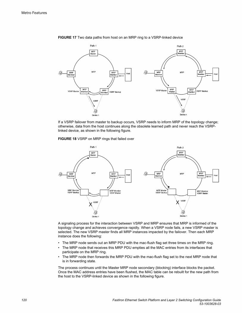
FIGURE 17 Two data paths from host on an MRP ring to a VSRP-linked device
If a VSRP failover from master to backup occurs, VSRP needs to inform MRP of the topology change;otherwise, data from the host continues along the obsolete learned path and never reach the VSRP-linked device, as shown in the following figure.
FIGURE 18 VSRP on MRP rings that failed over
A signaling process for the interaction between VSRP and MRP ensures that MRP is informed of thetopology change and achieves convergence rapidly. When a VSRP node fails, a new VSRP master isselected. The new VSRP master finds all MRP instances impacted by the failover. Then each MRPinstance does the following:
• The MRP node sends out an MRP PDU with the mac-flush flag set three times on the MRP ring.• The MRP node that receives this MRP PDU empties all the MAC entries from its interfaces that
participate on the MRP ring.• The MRP node then forwards the MRP PDU with the mac-flush flag set to the next MRP node that
is in forwarding state.
The process continues until the Master MRP node secondary (blocking) interface blocks the packet.Once the MAC address entries have been flushed, the MAC table can be rebuilt for the new path fromthe host to the VSRP-linked device as shown in the following figure.
Metro Features
120 FastIron Ethernet Switch Platform and Layer 2 Switching Configuration Guide53-1003628-03
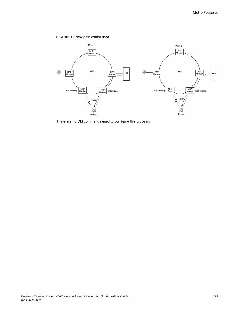
FIGURE 19 New path established
There are no CLI commands used to configure this process.
Metro Features
FastIron Ethernet Switch Platform and Layer 2 Switching Configuration Guide 12153-1003628-03

VSRP and MRP signaling
122 FastIron Ethernet Switch Platform and Layer 2 Switching Configuration Guide53-1003628-03
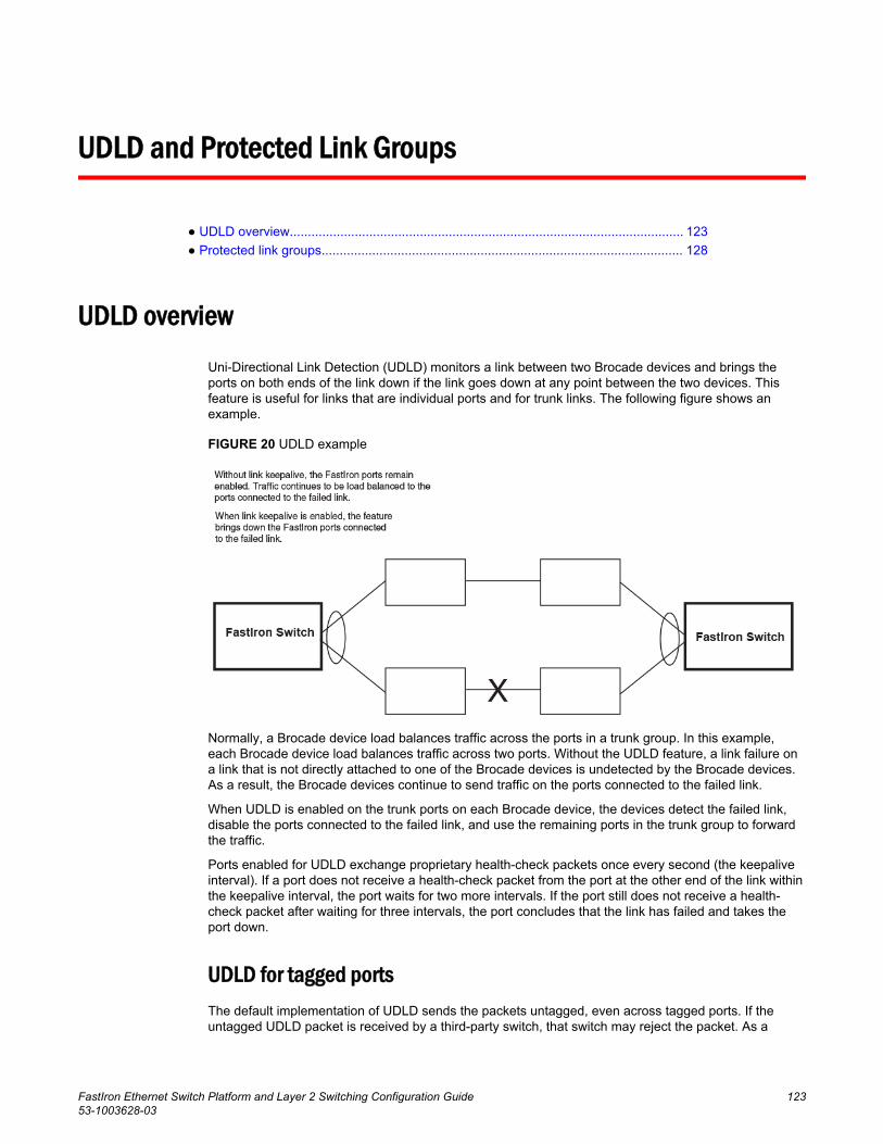
UDLD and Protected Link Groups
● UDLD overview............................................................................................................. 123● Protected link groups.................................................................................................... 128
UDLD overviewUni-Directional Link Detection (UDLD) monitors a link between two Brocade devices and brings theports on both ends of the link down if the link goes down at any point between the two devices. Thisfeature is useful for links that are individual ports and for trunk links. The following figure shows anexample.
FIGURE 20 UDLD example
Normally, a Brocade device load balances traffic across the ports in a trunk group. In this example,each Brocade device load balances traffic across two ports. Without the UDLD feature, a link failure ona link that is not directly attached to one of the Brocade devices is undetected by the Brocade devices.As a result, the Brocade devices continue to send traffic on the ports connected to the failed link.
When UDLD is enabled on the trunk ports on each Brocade device, the devices detect the failed link,disable the ports connected to the failed link, and use the remaining ports in the trunk group to forwardthe traffic.
Ports enabled for UDLD exchange proprietary health-check packets once every second (the keepaliveinterval). If a port does not receive a health-check packet from the port at the other end of the link withinthe keepalive interval, the port waits for two more intervals. If the port still does not receive a health-check packet after waiting for three intervals, the port concludes that the link has failed and takes theport down.
UDLD for tagged portsThe default implementation of UDLD sends the packets untagged, even across tagged ports. If theuntagged UDLD packet is received by a third-party switch, that switch may reject the packet. As a
FastIron Ethernet Switch Platform and Layer 2 Switching Configuration Guide 12353-1003628-03
result, UDLD may be limited only to Brocade devices, since UDLD may not function on third-partyswitches.
To solve this issue, you can configure ports to send out UDLD control packets that are tagged with aspecific VLAN ID. This feature also enables third party switches to receive the control packets that aretagged with the specified VLAN. For tagged operation, all of the following conditions must be met:
• A VLAN is specified when UDLD is configured• The port belongs to the configured VLAN as tagged member• All the devices across the UDLD link are in the same VLAN
For configuration details, refer to Enabling UDLD for tagged ports on page 125.
Configuration notes and feature limitations for UDLD• UDLD is supported only on Ethernet ports.• UDLD can be enabled on only one VLAN for tagged port.• To configure UDLD on a trunk group, you must enable and configure the feature on each port of the
group individually. Configuring UDLD on a trunk group primary port enables the feature on that portonly.
• Low UDLD link-keepalive interval and retry options are not recommended as they are moresensitive and prone to flaps.
• When UDLD is enabled on a trunk port, trunk threshold is not supported.• Dynamic trunking is not supported. If you want to configure a trunk group that contains ports on
which UDLD is enabled, you must remove the UDLD configuration from the ports. After you createthe trunk group, you can re-add the UDLD configuration.
• If MRP is also enabled on the device, Brocade recommends that you set the MRP preforwardingtime slightly higher than the default of 300 ms; for example, to 400 or 500 ms. Refer to Changingthe hello and preforwarding times on page 89.
Enabling UDLD
NOTEThis section shows how to configure UDLD for untagged control packets. To configure UDLD fortagged control packets, refer to Enabling UDLD for tagged ports on page 125.
To enable UDLD on a port, enter a command such as the following at the global CONFIG level of theCLI.
device(config)#link-keepalive ethernet 0/1/1To enable the feature on a trunk group, enter commands such as the following.
device(config)#link-keepalive ethernet 0/1/1 ethernet 0/1/2device(config)#link-keepalive ethernet 0/1/3 ethernet 0/1/4Syntax: [no] link-keepalive ethernet port [ to port | ethernet port ]
This command is not supported if you downgrade the device to FCX 6.0 or FSX5.1. In this case, usethe following command to configure multiple ports:
Syntax: [no] link-keepalive ethernet port [ ethernet port ]
Configuration notes and feature limitations for UDLD
124 FastIron Ethernet Switch Platform and Layer 2 Switching Configuration Guide53-1003628-03
Enabling UDLD for tagged portsTo enable ports to receive and send UDLD control packets tagged with a specific VLAN ID, entercommands such as the following.
device(config)#link-keepalive ethernet 1/1/18 vlan 22 This command enables UDLD on port 1/1/18 and allows UDLD control packet tagged with VLAN 22 tobe received and sent on port 1/1/18.
Syntax: [no] link-keepalive ethernet port [vlan vlan-ID]
For the vlan-ID variable, enter the ID of the VLAN that the UDLD control packets can contain to bereceived and sent on the port. If a VLAN ID is not specified, then UDLD control packets are sent out ofthe port as untagged packets.
NOTEYou must configure the same VLANs that will be used for UDLD on all devices across the network;otherwise, the UDLD link cannot be maintained.
Changing the Keepalive intervalBy default, ports enabled for UDLD send a link health-check packet once every 500 ms. You canchange the interval to a value from 1 - 60, where 1 is 100 ms, 2 is 200 ms, and so on. To change theinterval, enter a command such as the following.
device(config)#link-keepalive interval 4Syntax: [no] link-keepalive interval num
The num parameter specifies how often the ports send a UDLD packet. You can specify from 1 - 60, in100 ms increments. The default is 5 (500 ms).
Changing the Keepalive retriesBy default, a port waits one second to receive a health-check reply packet from the port at the other endof the link. If the port does not receive a reply, the port tries four more times by sending up to four morehealth-check packets. If the port still does not receive a reply after the maximum number of retries, theport goes down.
You can change the maximum number of keepalive attempts to a value from 3 - 64. To change themaximum number of attempts, enter a command such as the following.
device(config)#link-keepalive retries 10Syntax: [no] link-keepalive retries num
The num parameter specifies the maximum number of times the port will try the health check. You canspecify a value from 3 - 64. The default is 7.
Displaying UDLD informationThis section describes the commands used to display information about a UDLD configuration.
Enabling UDLD for tagged ports
FastIron Ethernet Switch Platform and Layer 2 Switching Configuration Guide 12553-1003628-03
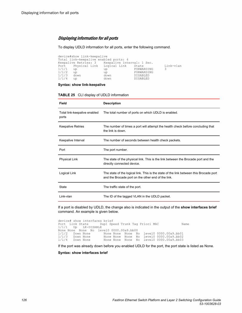
Displaying information for all ports
To display UDLD information for all ports, enter the following command.
device#show link-keepaliveTotal link-keepalive enabled ports: 4Keepalive Retries: 3 Keepalive Interval: 1 Sec.Port Physical Link Logical Link State Link-vlan1/1/1 up up FORWARDING 31/1/2 up up FORWARDING1/1/3 down down DISABLED1/1/4 up down DISABLEDSyntax: show link-keepalive
CLI display of UDLD information TABLE 25
Field Description
Total link-keepalive enabledports
The total number of ports on which UDLD is enabled.
Keepalive Retries The number of times a port will attempt the health check before concluding thatthe link is down.
Keepalive Interval The number of seconds between health check packets.
Port The port number.
Physical Link The state of the physical link. This is the link between the Brocade port and thedirectly connected device.
Logical Link The state of the logical link. This is the state of the link between this Brocade portand the Brocade port on the other end of the link.
State The traffic state of the port.
Link-vlan The ID of the tagged VLAN in the UDLD packet.
If a port is disabled by UDLD, the change also is indicated in the output of the show interfaces briefcommand. An example is given below.
device# show interfaces briefPort Link State Dupl Speed Trunk Tag Priori MAC Name1/1/1 Up LK-DISABLE None None None No level0 0000.00a9.bb001/1/2 Down None None None None No level0 0000.00a9.bb011/1/3 Down None None None None No level0 0000.00a9.bb021/1/4 Down None None None None No level0 0000.00a9.bb03If the port was already down before you enabled UDLD for the port, the port state is listed as None.
Syntax: show interfaces brief
Displaying information for all ports
126 FastIron Ethernet Switch Platform and Layer 2 Switching Configuration Guide53-1003628-03
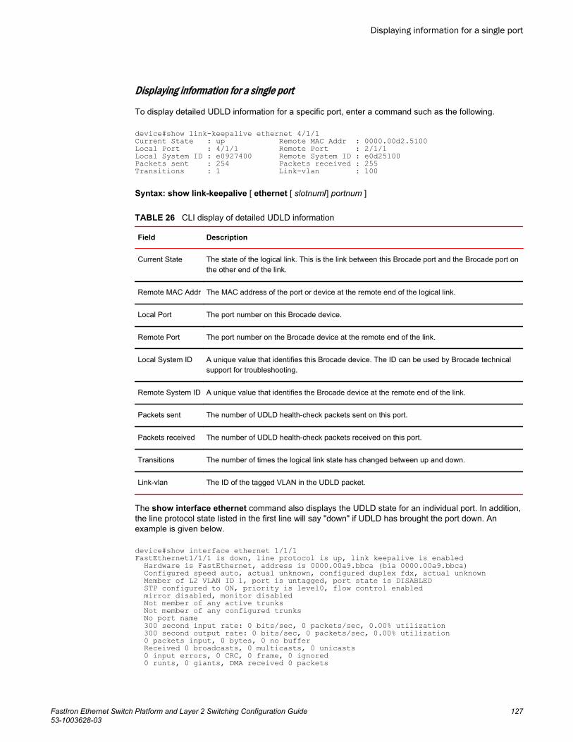
Displaying information for a single port
To display detailed UDLD information for a specific port, enter a command such as the following.
device#show link-keepalive ethernet 4/1/1Current State : up Remote MAC Addr : 0000.00d2.5100Local Port : 4/1/1 Remote Port : 2/1/1Local System ID : e0927400 Remote System ID : e0d25100Packets sent : 254 Packets received : 255Transitions : 1 Link-vlan : 100
Syntax: show link-keepalive [ ethernet [ slotnum/] portnum ]
CLI display of detailed UDLD information TABLE 26
Field Description
Current State The state of the logical link. This is the link between this Brocade port and the Brocade port onthe other end of the link.
Remote MAC Addr The MAC address of the port or device at the remote end of the logical link.
Local Port The port number on this Brocade device.
Remote Port The port number on the Brocade device at the remote end of the link.
Local System ID A unique value that identifies this Brocade device. The ID can be used by Brocade technicalsupport for troubleshooting.
Remote System ID A unique value that identifies the Brocade device at the remote end of the link.
Packets sent The number of UDLD health-check packets sent on this port.
Packets received The number of UDLD health-check packets received on this port.
Transitions The number of times the logical link state has changed between up and down.
Link-vlan The ID of the tagged VLAN in the UDLD packet.
The show interface ethernet command also displays the UDLD state for an individual port. In addition,the line protocol state listed in the first line will say "down" if UDLD has brought the port down. Anexample is given below.
device#show interface ethernet 1/1/1FastEthernet1/1/1 is down, line protocol is up, link keepalive is enabled Hardware is FastEthernet, address is 0000.00a9.bbca (bia 0000.00a9.bbca) Configured speed auto, actual unknown, configured duplex fdx, actual unknown Member of L2 VLAN ID 1, port is untagged, port state is DISABLED STP configured to ON, priority is level0, flow control enabled mirror disabled, monitor disabled Not member of any active trunks Not member of any configured trunks No port name 300 second input rate: 0 bits/sec, 0 packets/sec, 0.00% utilization 300 second output rate: 0 bits/sec, 0 packets/sec, 0.00% utilization 0 packets input, 0 bytes, 0 no buffer Received 0 broadcasts, 0 multicasts, 0 unicasts 0 input errors, 0 CRC, 0 frame, 0 ignored 0 runts, 0 giants, DMA received 0 packets
Displaying information for a single port
FastIron Ethernet Switch Platform and Layer 2 Switching Configuration Guide 12753-1003628-03
19 packets output, 1216 bytes, 0 underruns Transmitted 0 broadcasts, 19 multicasts, 0 unicasts 0 output errors, 0 collisions, DMA transmitted 19 packets
In this example, the port has been brought down by UDLD. Notice that in addition to the information inthe first line, the port state on the fourth line of the display is listed as DISABLED.
Clearing UDLD statisticsTo clear UDLD statistics, enter the following command.
device#clear link-keepalive statisticsSyntax: clear link-keepalive statistics
This command clears the Packets sent, Packets received, and Transitions counters in the show linkkeepalive ethernet [slotnum /]portnum display.
Protected link groups
NOTEProtected Link group is not supported on ICX 7750, ICX 7250 and ICX 7450 devices.
A protected link group minimizes disruption to the network by protecting critical links from loss of dataand power. In a protected link group, one port in the group acts as the primary or active link, and theother ports act as secondary or standby links. The active link carries the traffic. If the active link goesdown, one of the standby links takes over.
During normal operation, the active port in a protected link group is enabled and the standby ports arelogically disabled. If the active port fails, the Brocade device immediately enables one of the standbyports, and switches traffic to the standby port. The standby port becomes the new, active port.
About active portsWhen you create a protected link group, you can optionally specify which port in the protected linkgroup is the active port. If you do not explicitly configure an active port, the Brocade devicedynamically assigns one. A dynamic active port is the first port in the protected link group that comesup (usually the lowest numbered port in the group).
Static and dynamic active ports operate as follows:
• A static active port (an active port that you explicitly configured) pre-empts other ports in theprotected link group. So, if a static active link comes back up after a failure, the Brocade device willrevert to this link as the active link.
• A dynamic active port (an active port assigned by the software) is non-pre-emptive. Therefore, if adynamic active link comes back up after a failure, the Brocade device does not revert to this link,but continues carrying traffic on the current active link.
Using UDLD with protected link groupsYou can use UDLD with protected link groups to detect uni-directional link failures and to improve thespeed at which the device detects a failure in the link. Use UDLD and protected link groups
Clearing UDLD statistics
128 FastIron Ethernet Switch Platform and Layer 2 Switching Configuration Guide53-1003628-03
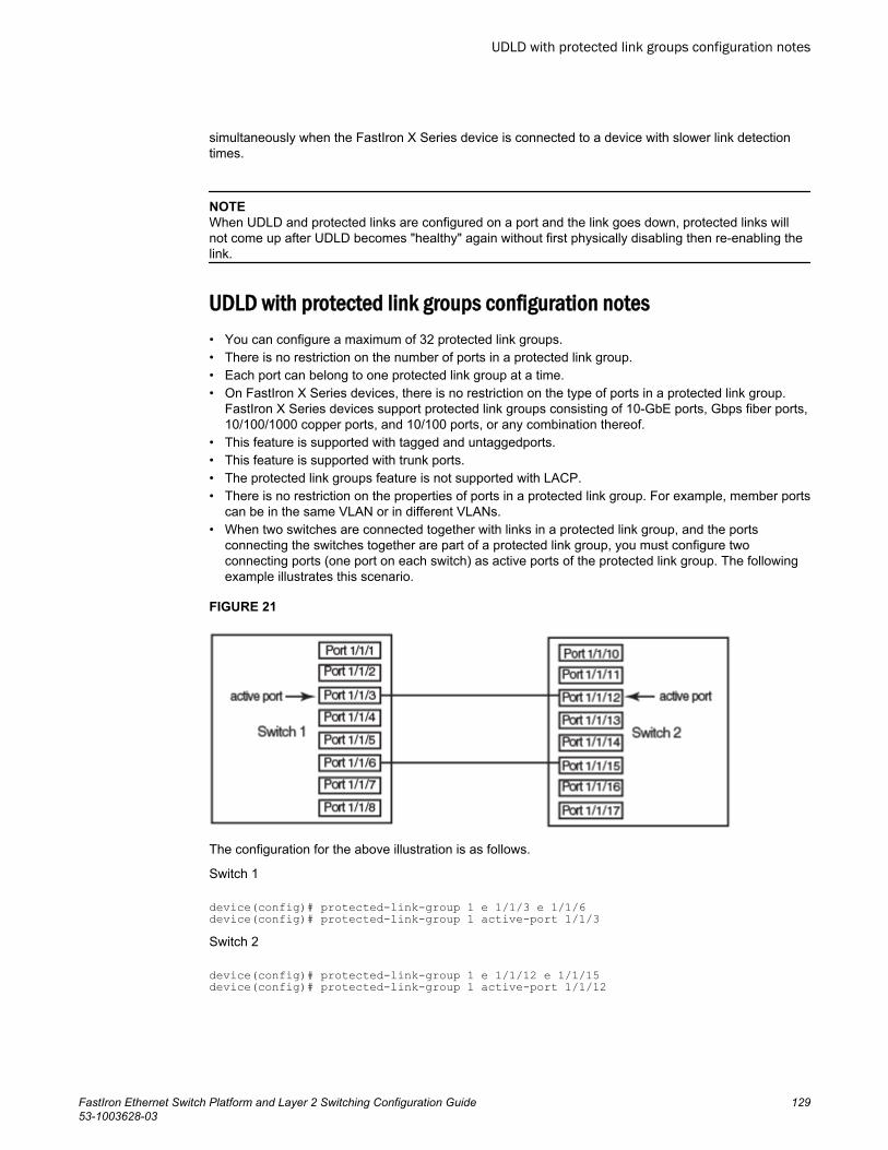
simultaneously when the FastIron X Series device is connected to a device with slower link detectiontimes.
NOTEWhen UDLD and protected links are configured on a port and the link goes down, protected links willnot come up after UDLD becomes "healthy" again without first physically disabling then re-enabling thelink.
UDLD with protected link groups configuration notes• You can configure a maximum of 32 protected link groups.• There is no restriction on the number of ports in a protected link group.• Each port can belong to one protected link group at a time.• On FastIron X Series devices, there is no restriction on the type of ports in a protected link group.
FastIron X Series devices support protected link groups consisting of 10-GbE ports, Gbps fiber ports,10/100/1000 copper ports, and 10/100 ports, or any combination thereof.
• This feature is supported with tagged and untaggedports.• This feature is supported with trunk ports.• The protected link groups feature is not supported with LACP.• There is no restriction on the properties of ports in a protected link group. For example, member ports
can be in the same VLAN or in different VLANs.• When two switches are connected together with links in a protected link group, and the ports
connecting the switches together are part of a protected link group, you must configure twoconnecting ports (one port on each switch) as active ports of the protected link group. The followingexample illustrates this scenario.
FIGURE 21
The configuration for the above illustration is as follows.
Switch 1
device(config)# protected-link-group 1 e 1/1/3 e 1/1/6device(config)# protected-link-group 1 active-port 1/1/3Switch 2
device(config)# protected-link-group 1 e 1/1/12 e 1/1/15device(config)# protected-link-group 1 active-port 1/1/12
UDLD with protected link groups configuration notes
FastIron Ethernet Switch Platform and Layer 2 Switching Configuration Guide 12953-1003628-03
Creating a protected link group and assigning an active portFollow the steps given below to create a protected link group.
1. Specify the member ports in the protected link group. Enter a command such as the following.
device(config)#protected-link-group 10 e 1 to 4 2. Optionally specify which port will be the active port for the protected link group. Enter a command
such as the following.
device(config)#protected-link-group 10 active-port 1
NOTEIf you do not explicitly configure an active port, the Brocade device automatically assigns one as thefirst port in the protected link group to come up.
These commands configure port e1 as the active port and ports e2 - e4 as standby ports. If port 1goes down, the Brocade device enables the first available standby port, and switches the traffic tothat port. Since the above configuration consists of a statically configured active port, the active portpre-empts other ports in the protected link group. Refer to About active ports on page 128.
Syntax: [no] protected-link-group group-ID ethernet port to port
The group-ID parameter specifies the protected link group number. Enter a number from 1 - 32.
Syntax: [no] protected-link-group group-ID active-port ethernet port
The group-ID parameter specifies the protected link group number. Enter a number from 1 - 32.
Viewing information about protected link groups
You can use the following show commands to view information about protected link groups:
• show protected-link-group• show interface brief• show interface
The following shows example output for the show protected-link-group command.
device#show protected-link-groupGroup ID: 1Member Port(s): ethe 1 to 7Configured Active Port: 7Current Active Port: 7Standby Port(s): ethe 5Total Number of Protected Link Groups: 1Syntax: show protected-link-group [ group-ID ]
CLI display of protected link group information TABLE 27
Field Description
Group ID The ID number of the protected link group.
Member Port(s) The ports that are members of the protected link group.
Configured Active Port The statically configured active port. If you do not statically configure an active port,this value will be "None".
Current Active Port The current active port for the protected link group. If all member ports are down, thisvalue will be "None".
Creating a protected link group and assigning an active port
130 FastIron Ethernet Switch Platform and Layer 2 Switching Configuration Guide53-1003628-03
CLI display of protected link group information (Continued)TABLE 27
Field Description
Standby Port(s) The member ports that are on standby.
The show interface brief command also displays information about protected link groups.
device#show int brief e 3 to 4Port Link State Dupl Speed Trunk Tag Priori MAC Name 3 Up Inactive Full Auto None Yes level0 0000.00a8.71404 Up Forward Full 1G None Yes level0 0000.00a8.7140In the above output, the State of port 3 is Inactive , which means port 3 is an inactive port in aprotected link group. For active ports in a protected link group, the State will be Active.
Syntax: show interface brief ethernet port
The show interface command also displays information about protected link groups.
device#show int e 3GigabitEthernet3 is up, line protocol is up, link keepalive is enabledPort up for 60 seconds Hardware is GigabitEthernet, address is 0000.00a8.7140 (bia 0000.00a8.7142) Configured speed auto, actual 1Gbit, configured duplex fdx, actual fdx Configured mdi mode AUTO, actual MDIX Member of 3 L2 VLANs, port is tagged, port state is protected-link-inactive BPDU guard is Disabled, ROOT protect is Disabled Link Error Dampening is Disabled STP configured to ON, priority is level0 .... some lines ommitted for brevityIn the above output, the port state is protected-link-inactive which means port 3 is an inactive portin a protected link group.
Syntax: show interface ethernet port
UDLD and Protected Link Groups
FastIron Ethernet Switch Platform and Layer 2 Switching Configuration Guide 13153-1003628-03

Creating a protected link group and assigning an active port
132 FastIron Ethernet Switch Platform and Layer 2 Switching Configuration Guide53-1003628-03
Link Aggregation
● Overview of link aggregation.........................................................................................133● LAG formation rules...................................................................................................... 134● Configuration notes for FastIron devices in a traditional stack......................................135● Maximum number of LAGs........................................................................................... 137● Migrating from a previous release to 08.0.00a LAG or LACP configuration................. 138● Downgrade considerations............................................................................................139● LAG Load Sharing.........................................................................................................140● LAG hashing on stacking products .............................................................................. 141● Configuring a LAG.........................................................................................................144● Deploying a LAG........................................................................................................... 149● Preboot eXecution Environment boot support.............................................................. 160● User-configured peer information per LACP................................................................. 161
Overview of link aggregationThis chapter describes how to configure Link Aggregation Groups (LAG). Beginning with FastIron08.0.00a, you can use a single interface to configure any of the following LAG types:
Static LAGs - These LAGs are manually-configured aggregate links containing multiple ports.
Dynamic LAGs - This LAG type uses the Link Aggregation Control Protocol (LACP), to maintainaggregate links over multiple port. LACP PDUs are exchanged between ports on each device todetermine if the connection is still active. The LAG then shuts down ports whose connection is no longeractive.
NOTEThe LAG functionality was referred to as Trunk Groups in previous releases.
Keep Alive LAGs - In a Keep Alive LAG a single connection between a single port on 2 Brocade devicesis established. In a keep alive LAG, LACP PDUs are exchanged between the 2 ports to determine if theconnection between the devices is still active. If it is determined that the connection is no longer active,the ports are blocked.
NOTEThe Keep Alive LAG functionality was referred to as Single Link LACP in previous releases.
The new LAG configuration procedures supersede the previous configurations procedures for LAGsand Dynamic Link Aggregation. When a Brocade device is upgraded to 08.0.00a any configurations forLAGs or Dynamic Link Aggregation defined in releases prior to 08.0.00a will be converted to a 08.0.00a(and later) compatible LAG configuration. Details about how this conversion is performed are describedin Migrating from a previous release to 08.0.00a LAG or LACP configuration on page 138. LAGformation rules
FastIron Ethernet Switch Platform and Layer 2 Switching Configuration Guide 13353-1003628-03
LAG formation rules• A port can be a member of only a single LAG, which can be a static, dynamic, or keep-alive LAG.• Flexible LAG membership: Any number or combination of ports between 1 and 16 within the device
can be used to configure a LAG. FSX-third generation modules in an all third-generation systemcan have 1 to 12 ports. For Brocade ICX 6430, Brocade ICX 6450, Brocade ICX 6610, and BrocadeICX 6650 devices, the port range is between 1 and 8. Brocade ICX 7750, Brocade ICX 7450, andBrocade ICX 7250 devices support a maximum of 256 LAGs and each LAG supports a maximum of16 member ports. The maximum number of LAG ports is checked when adding ports to a LAG.Ports in a LAG can be on different line card modules in a chassis or on different units in a stack.
NOTEThough the Brocade FastIron devices support a total of 4096 (256x16) LAGs on the Brocade ICX7750, Brocade ICX 7450, and Brocade ICX 7250 devices, the devices can scale up to a maximumof 2048 LAG members (256x8) only.
• Brocade FastIron devices cannot form a LAG between two stacks using a Brocade optical breakoutcable because the cable is not supported on a stack.
• All ports configured in a LAG must be of equal bandwidth, for example, all 10 GbE ports.• All ports configured in a LAG must be configured with the same port attributes.• LAG formation rules are checked when a static or dynamic LAG is deployed.• A LAG must have its primary port selected before it can be deployed.• All ports configured in a LAG must be configured in the same VLAN.• Layer 2 requirements:
The LAG is rejected if the LAG ports:
• Do not have the same untagged VLAN component• Do not share the same VLAN membership or do not share the same uplink VLAN membership• Do not share the same protocol-VLAN configuration• Are configured as mainly primary and secondary interfaces
• Layer 3 requirements:
The LAG is rejected if any of the secondary LAG port has any Layer 3 configurations, such as IPv4or IPv6 address, OSPF, RIP, RIPng, IS-IS, and so on.
• Layer 4 (ACL) requirements:
All LAG ports must have the same ACL configurations; otherwise, the LAG is rejected.• All LAG member properties must match the primary port of the LAG with respect to the following
parameters:
‐ Port tag type (untagged or tagged port)‐ Port dual-mode‐ Default port speed and duplex‐ Configured port speed and duplex‐ TOS-based configuration: During deployment, the configuration on the primary port is replicated
to all ports. On undeployment, each port inherits the same TOS-based QoS configuration.
To change port parameters, you must change them on the primary port. The software automaticallyapplies the changes to the other ports in the LAG.
• The device on the other end of the LAG link must support the same number of ports in the link. Forexample, if you configure a 3-port LAG on the FSX and the other end is a different type of switch,make sure the other switch can support a 3-port LAG.
LAG formation rules
134 FastIron Ethernet Switch Platform and Layer 2 Switching Configuration Guide53-1003628-03
• Legacy ports and 48 Gbps copper ports cannot be members of the same LAG in hardwareconfigurations such as the following:
‐ 48-port 10/100/1000 Mbps (RJ-45) Ethernet PoE interface module (SX-FI48GPP) and IPv4 orIPv6 interface modules or management modules with user ports
• A combination of different generations of ports cannot be members of the same LAG under thefollowing hardware configurations:
‐ 24-port fiber and copper Ethernet PoE or fiber interfaces (SX-FI24GPP, SX-FI24HF) and IPv4 orIPv6 interface modules or management modules with user ports
‐ 2-port 10 GbE and 8-port 10 GbE interfaces (SX-FI2XG, SX-FI8XG) and the IPv4 or IPv6 interfacemodules or management modules with user ports
• A combination of copper and fiber ports, even if they are of the same speed, cannot be members ofthe same LAG.
• The FastIron SX chassis supports up to 12 ports per LAG and a maximum of 255 LAGs only whenthe following third-generation interface modules are installed in the chassis:
‐ SX-FI48GPP: 48-port 10/100/1000 Mbps Ethernet PoE interface module‐ SX-FI24GPP: 24-port Gigabit Ethernet copper interface module‐ SX-FI24HF: 24-port Gigabit Ethernet fiber interface module‐ SX-FI2XG: 2-port 10 Gigabit Ethernet interface module‐ SX-FI8XG: 8-port 10 Gigabit Ethernet interface module
• A cross-module LAG is only supported between the same generation SX cards.• A LAG is supported on 1 GbE,10 GbE, or 40 GbE ports.• 1 GbE and 10 GbE ports cannot be combined in the same LAG.• Port assignment on a module need not be consecutive. The port range can contain gaps. For
example, you can configure ports 1, 3, and 4 (excluding 2).• Although the FastIron devices have port ranges, they do not apply to LAGs.• You can select any port to be the primary port of the LAG.• All the ports must be connected to the same physical or logical device at the other end.• The sFlow configuration enabled on the primary port of a LAG is applicable to all the LAG ports.
Disabling the sFlow on the primary port of a LAG removes the configuration from all the LAG ports.
Configuration notes for FastIron devices in a traditional stackIn a Brocade traditional stack system, a LAG may have port members distributed across multiple stackunits. Both static and dynamic LAGs are supported.
NOTECascaded LAGs between stack units are supported on Brocade ICX devices only.
The following notes apply to FastIron stackable devices that are part of a traditional stack:
• If a stack unit fails or is removed from the stack, its static LAG configuration becomes a reservedconfiguration on the Active Controller. Any remaining ports of the static LAG in the traditional stackcontinue to function.
• When a new stack unit is added to a traditional stack, the new unit receives the running configurationand LAG information, including a list of ports that are up and are members of a LAG, from the ActiveController.
• Before merging two traditional stack devices, make sure that there are no static LAGs configuredbetween them. This can result in self-looped ports.
• You cannot configure a LAG between cross units in a mixed stack.
Configuration notes for FastIron devices in a traditional stack
FastIron Ethernet Switch Platform and Layer 2 Switching Configuration Guide 13553-1003628-03
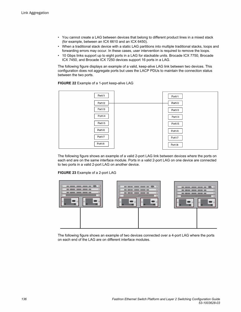
• You cannot create a LAG between devices that belong to different product lines in a mixed stack(for example, between an ICX 6610 and an ICX 6450).
• When a traditional stack device with a static LAG partitions into multiple traditional stacks, loops andforwarding errors may occur. In these cases, user intervention is required to remove the loops.
• 10 Gbps links support up to eight ports in a LAG for stackable units. Brocade ICX 7750, BrocadeICX 7450, and Brocade ICX 7250 devices support 16 ports in a LAG.
The following figure displays an example of a valid, keep-alive LAG link between two devices. Thisconfiguration does not aggregate ports but uses the LACP PDUs to maintain the connection statusbetween the two ports.
FIGURE 22 Example of a 1-port keep-alive LAG
The following figure shows an example of a valid 2-port LAG link between devices where the ports oneach end are on the same interface module. Ports in a valid 2-port LAG on one device are connectedto two ports in a valid 2-port LAG on another device.
FIGURE 23 Example of a 2-port LAG
The following figure shows an example of two devices connected over a 4-port LAG where the portson each end of the LAG are on different interface modules.
Link Aggregation
136 FastIron Ethernet Switch Platform and Layer 2 Switching Configuration Guide53-1003628-03
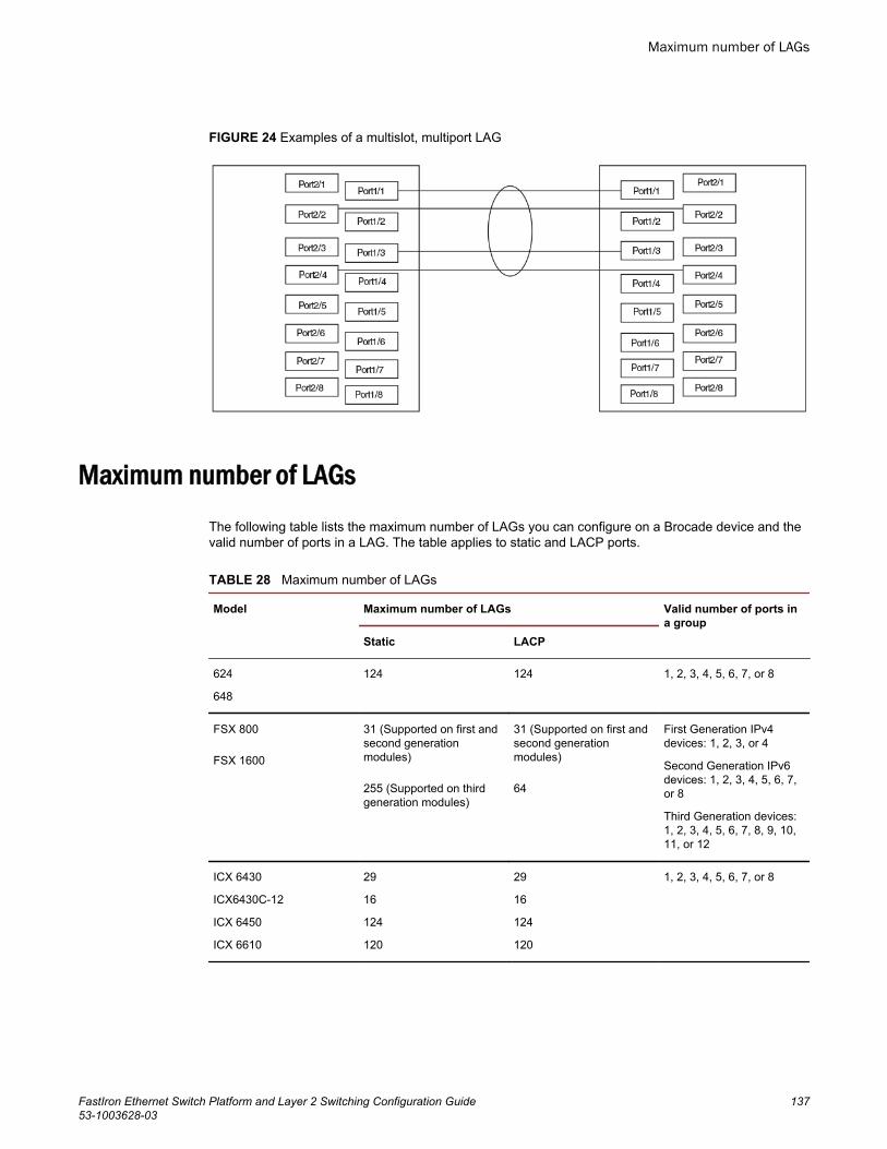
FIGURE 24 Examples of a multislot, multiport LAG
Maximum number of LAGsThe following table lists the maximum number of LAGs you can configure on a Brocade device and thevalid number of ports in a LAG. The table applies to static and LACP ports.
Maximum number of LAGs TABLE 28
Model Maximum number of LAGs Valid number of ports ina group
Static LACP
624
648
124 124 1, 2, 3, 4, 5, 6, 7, or 8
FSX 800
FSX 1600
31 (Supported on first andsecond generationmodules)
255 (Supported on thirdgeneration modules)
31 (Supported on first andsecond generationmodules)
64
First Generation IPv4devices: 1, 2, 3, or 4
Second Generation IPv6devices: 1, 2, 3, 4, 5, 6, 7,or 8
Third Generation devices:1, 2, 3, 4, 5, 6, 7, 8, 9, 10,11, or 12
ICX 6430
ICX6430C-12
ICX 6450
ICX 6610
29
16
124
120
29
16
124
120
1, 2, 3, 4, 5, 6, 7, or 8
Maximum number of LAGs
FastIron Ethernet Switch Platform and Layer 2 Switching Configuration Guide 13753-1003628-03
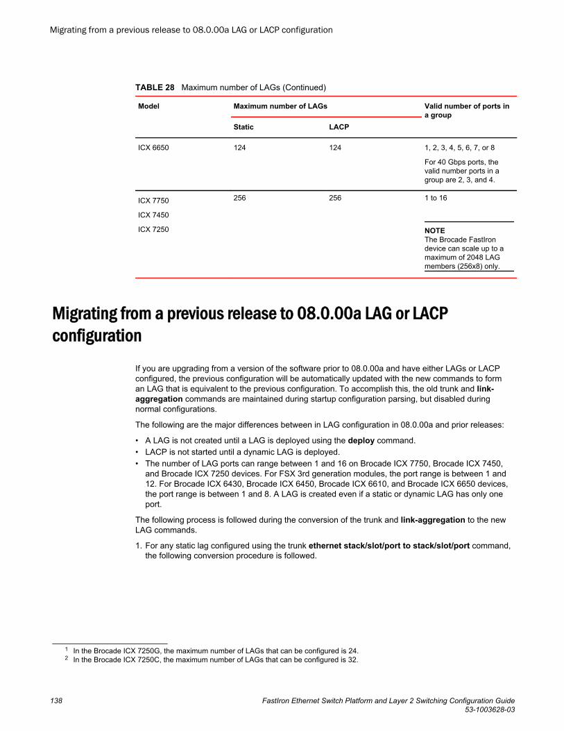
Maximum number of LAGs (Continued)TABLE 28
Model Maximum number of LAGs Valid number of ports ina group
Static LACP
ICX 6650 124 124 1, 2, 3, 4, 5, 6, 7, or 8
For 40 Gbps ports, thevalid number ports in agroup are 2, 3, and 4.
ICX 7750
ICX 7450
ICX 7250
256 256 1 to 16
NOTEThe Brocade FastIrondevice can scale up to amaximum of 2048 LAGmembers (256x8) only.
Migrating from a previous release to 08.0.00a LAG or LACPconfiguration
If you are upgrading from a version of the software prior to 08.0.00a and have either LAGs or LACPconfigured, the previous configuration will be automatically updated with the new commands to forman LAG that is equivalent to the previous configuration. To accomplish this, the old trunk and link-aggregation commands are maintained during startup configuration parsing, but disabled duringnormal configurations.
The following are the major differences between in LAG configuration in 08.0.00a and prior releases:
• A LAG is not created until a LAG is deployed using the deploy command.• LACP is not started until a dynamic LAG is deployed.• The number of LAG ports can range between 1 and 16 on Brocade ICX 7750, Brocade ICX 7450,
and Brocade ICX 7250 devices. For FSX 3rd generation modules, the port range is between 1 and12. For Brocade ICX 6430, Brocade ICX 6450, Brocade ICX 6610, and Brocade ICX 6650 devices,the port range is between 1 and 8. A LAG is created even if a static or dynamic LAG has only oneport.
The following process is followed during the conversion of the trunk and link-aggregation to the newLAG commands.
1. For any static lag configured using the trunk ethernet stack/slot/port to stack/slot/port command,the following conversion procedure is followed.
1 In the Brocade ICX 7250G, the maximum number of LAGs that can be configured is 24.2 In the Brocade ICX 7250C, the maximum number of LAGs that can be configured is 32.
Migrating from a previous release to 08.0.00a LAG or LACP configuration
138 FastIron Ethernet Switch Platform and Layer 2 Switching Configuration Guide53-1003628-03
a) A static LAG is created containing the port list specified in the trunk command. This LAG is thenautomatically deployed.
b) The lowest-numbered port from the original trunk list is selected as the primary port of the LAG.c) The converted LAG is named "LAG_x", where "x" is a unique number assigned by the system
starting from 1.2. For any dynamic link aggregation (LACP) group configured using the port-level link-aggregate
commands, the following conversion procedure is followed.a) A dynamic LAG is created by grouping all ports in the original configuration having the same link-
aggregation key.b) If link-aggregate active/passive is configured originally, the converted dynamic LAG is
configured as deployed, otherwise is not be converted because such ports were originally notoperating under LACP.
c) If the original mode is passive, the converted dynamic LAG will be configured as deploy passive .Otherwise active mode is the default.
d) The timeout configuration set by the command link-aggregate configure timeout will beconverted to the lacp-timeout command.
e) The value of the link-aggregate configure key command is used in the conversion in determiningthe set of ports that form an LAG, so prior to upgrade the key must be configured on all the link-agg groups. In the new LAG user interface, there is no need for a user to explicitly configure a key.Each dynamic LAG will automatically select a unique key for the system. Hence the originalconfigured key will not be retained.
NOTEYou cannot copy configurations to the running configurations from a TFTP server. It is notsupported when you upgrade from a software version earlier to 08.0.00a to 8.0 configuration. Theconfiguration must be saved on flash as startup configuration and reload is required without write-memory.
f) The command link-aggregate configure system-priority is retired and will not be directlyconverted. This value is currently not in use by the system's LACP protocol processing, and willmaintain a default value of 1.
g) The lowest-numbered port will be selected as the primary port of the LAG.h) Port names configured in the original interface configuration will be converted to port names within
the LAG.i) The converted LAG will be named "LAG_x", where "x" is a unique number assigned by the system
starting from 1.
Downgrade considerationsWhen you downgrade to an earlier software version, all the existing LAG configurations will be lost.
NOTEWhen you downgrade to a software version that does not support 256 LAGs, only the first 128 trunkgroups are deployed and the remaining LAGs will remain in the undeployed state. This is applicable toBrocade ICX 7750, Brocade ICX 7450, and Brocade ICX 7250 devices only.
Downgrade considerations
FastIron Ethernet Switch Platform and Layer 2 Switching Configuration Guide 13953-1003628-03
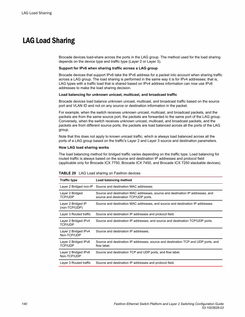
LAG Load Sharing
Brocade devices load-share across the ports in the LAG group. The method used for the load sharingdepends on the device type and traffic type (Layer 2 or Layer 3).
Support for IPv6 when sharing traffic across a LAG group
Brocade devices that support IPv6 take the IPv6 address for a packet into account when sharing trafficacross a LAG group. The load sharing is performed in the same way it is for IPv4 addresses; that is,LAG types with a traffic load that is shared based on IPv4 address information can now use IPv6addresses to make the load sharing decision.
Load balancing for unknown unicast, multicast, and broadcast traffic
Brocade devices load balance unknown unicast, multicast, and broadcast traffic based on the sourceport and VLAN ID and not on any source or destination information in the packet.
For example, when the switch receives unknown unicast, multicast, and broadcast packets, and thepackets are from the same source port, the packets are forwarded to the same port of the LAG group.Conversely, when the switch receives unknown unicast, multicast, and broadcast packets, and thepackets are from different source ports, the packets are load balanced across all the ports of the LAGgroup.
Note that this does not apply to known unicast traffic, which is always load balanced across all theports of a LAG group based on the traffic's Layer 2 and Layer 3 source and destination parameters.
How LAG load sharing works
The load balancing method for bridged traffic varies depending on the traffic type. Load balancing forrouted traffic is always based on the source and destination IP addresses and protocol field(applicable only for Brocade ICX 7750, Brocade ICX 7450, and Brocade ICX 7250 stackable devices).
LAG Load sharing on FastIron devicesTABLE 29
Traffic type Load balancing method
Layer 2 Bridged non-IP Source and destination MAC addresses
Layer 2 BridgedTCP/UDP
Source and destination MAC addresses, source and destination IP addresses, andsource and destination TCP/UDP ports.
Layer 2 Bridged IP(non-TCP/UDP)
Source and destination MAC addresses, and source and destination IP addresses.
Layer 3 Routed traffic Source and destination IP addresses and protocol field.
Layer 2 Bridged IPv4TCP/UDP
Source and destination IP addresses, and source and destination TCP/UDP ports.
Layer 2 Bridged IPv4Non-TCP/UDP
Source and destination IP addresses.
Layer 2 Bridged IPv6TCP/UDP
Source and destination IP addresses, source and destination TCP and UDP ports, andflow label.
Layer 2 Bridged IPv6Non-TCP/UDP
Source and destination TCP and UDP ports, and flow label.
Layer 3 Routed traffic Source and destination IP addresses and protocol field.
LAG Load Sharing
140 FastIron Ethernet Switch Platform and Layer 2 Switching Configuration Guide53-1003628-03
LAG hashing on stacking productsLAG hashing on stacking products is required when multicast routing is configured on a tunnel interfaceand the IP multicast packets terminate in the tunnel (for example, when the ip pim, ip pim-sparse , orip igmp proxy multicast routing commands are configured on a tunnel interface).
Removing Layer 2 information from LAG hash output
NOTERemoving Layer 2 information from LAG hash output is not supported on FastIron X Series devices andon Brocade ICX 7750, Brocade ICX 7450, and Brocade ICX 7250 devices.
FastIron stackable devices support the option to exclude Layer 2 information in the LAG hashcalculation for IP packets.
Brocade(config)# lag-hash exclude-l2macThe lag-hash exclude-l2mac command removes Layer 2 information (text in bold) to the followingload-balancing parameters:
• Non-IP: Source and destination MAC addresses• IPv4 TCP/UDP: Source and destination IP addresses, and source and destination TCP/UDP ports,
Source MAC , Destination MAC• IPv4 Non-TCP/UDP: Source and destination IP addresses, Source MAC , Destination MAC• IPv6 TCP/UDP: Source and destination IP addresses, source and destination TCP and UDP ports,
and flow label, Source MAC , Destination MAC• IPv6 Non-TCP/UDP: Source and destination TCP and UDP ports, and flow label, Source MAC ,
Destination MAC
Symmetric load balancingSymmetric load balancing is a mechanism of interchanging the source and destination addresses toensure that bidirectional traffic specific to a particular source and destination address pair flows out ofthe same member of a trunk group.
NOTESymmetric load balancing is not supported on non-IP data traffic.
For many monitoring and security applications, bidirectional conversations flowing through the systemmust be carried on the same port of a LAG. For network telemetry applications, network traffic is tappedand sent to a Brocade device, which can hash selected traffic to the application servers' downstream.Each server analyzes the bidirectional conversations. Therefore, the Brocade devices must enablesymmetric load balancing to accomplish bidirectional conversations. In addition, the firewall between theBrocade devices can be configured to allow the bidirectional conversations per link of the LAG. Thesenetwork telemetry applications also require symmetric load balancing on the LAGs between theBrocade devices.
NOTESymmetric load balancing is supported on Brocade ICX 7750, Brocade ICX 7450, and Brocade ICX7250 devices only.
LAG hashing on stacking products
FastIron Ethernet Switch Platform and Layer 2 Switching Configuration Guide 14153-1003628-03
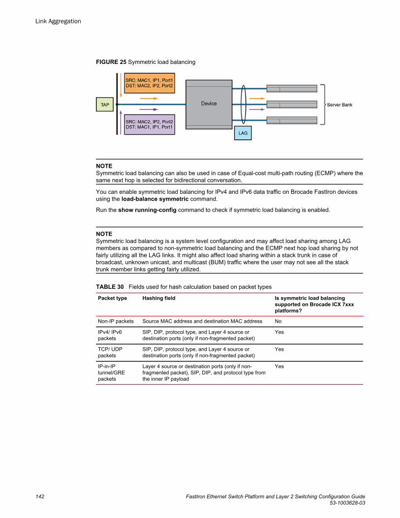
FIGURE 25 Symmetric load balancing
NOTESymmetric load balancing can also be used in case of Equal-cost multi-path routing (ECMP) where thesame next hop is selected for bidirectional conversation.
You can enable symmetric load balancing for IPv4 and IPv6 data traffic on Brocade FastIron devicesusing the load-balance symmetric command.
Run the show running-config command to check if symmetric load balancing is enabled.
NOTESymmetric load balancing is a system level configuration and may affect load sharing among LAGmembers as compared to non-symmetric load balancing and the ECMP next hop load sharing by notfairly utilizing all the LAG links. It might also affect load sharing within a stack trunk in case ofbroadcast, unknown unicast, and multicast (BUM) traffic where the user may not see all the stacktrunk member links getting fairly utilized.
Fields used for hash calculation based on packet typesTABLE 30
Packet type Hashing field Is symmetric load balancingsupported on Brocade ICX 7xxxplatforms?
Non-IP packets Source MAC address and destination MAC address No
IPv4/ IPv6packets
SIP, DIP, protocol type, and Layer 4 source ordestination ports (only if non-fragmented packet)
Yes
TCP/ UDPpackets
SIP, DIP, protocol type, and Layer 4 source ordestination ports (only if non-fragmented packet)
Yes
IP-in-IPtunnel/GREpackets
Layer 4 source or destination ports (only if non-fragmented packet), SIP, DIP, and protocol type fromthe inner IP payload
Yes
Link Aggregation
142 FastIron Ethernet Switch Platform and Layer 2 Switching Configuration Guide53-1003628-03
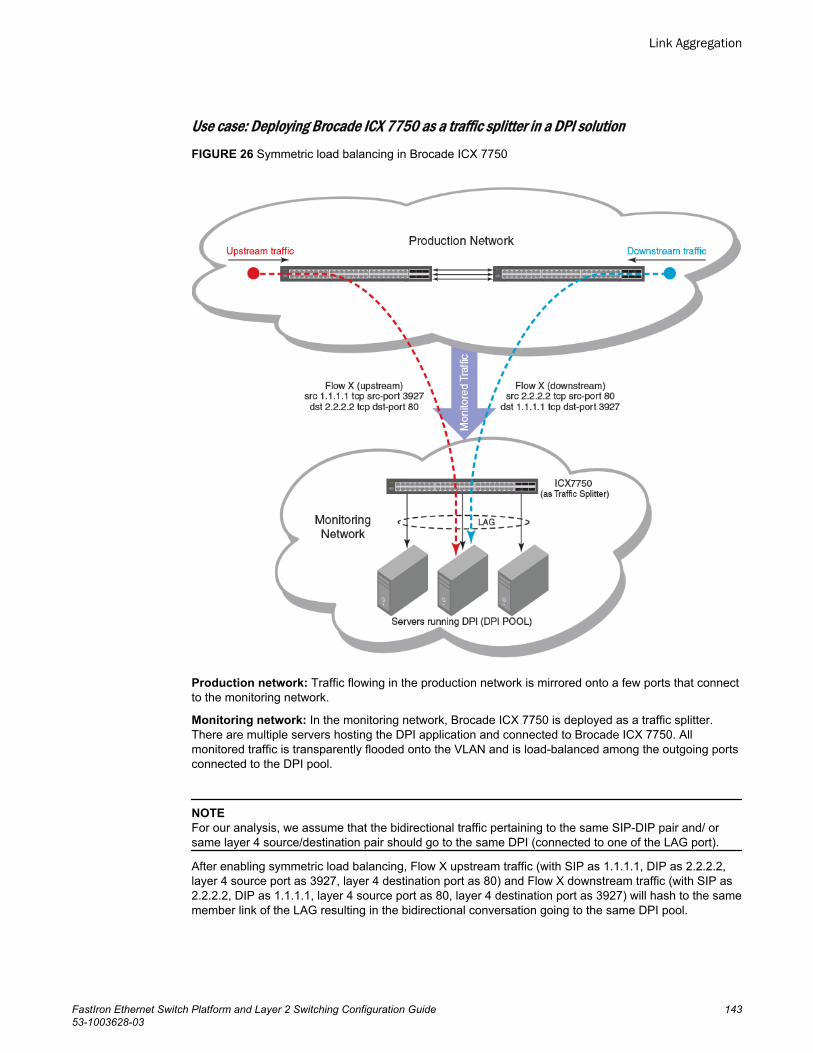
Use case: Deploying Brocade ICX 7750 as a traffic splitter in a DPI solutionFIGURE 26 Symmetric load balancing in Brocade ICX 7750
Production network: Traffic flowing in the production network is mirrored onto a few ports that connectto the monitoring network.
Monitoring network: In the monitoring network, Brocade ICX 7750 is deployed as a traffic splitter.There are multiple servers hosting the DPI application and connected to Brocade ICX 7750. Allmonitored traffic is transparently flooded onto the VLAN and is load-balanced among the outgoing portsconnected to the DPI pool.
NOTEFor our analysis, we assume that the bidirectional traffic pertaining to the same SIP-DIP pair and/ orsame layer 4 source/destination pair should go to the same DPI (connected to one of the LAG port).
After enabling symmetric load balancing, Flow X upstream traffic (with SIP as 1.1.1.1, DIP as 2.2.2.2,layer 4 source port as 3927, layer 4 destination port as 80) and Flow X downstream traffic (with SIP as2.2.2.2, DIP as 1.1.1.1, layer 4 source port as 80, layer 4 destination port as 3927) will hash to the samemember link of the LAG resulting in the bidirectional conversation going to the same DPI pool.
Link Aggregation
FastIron Ethernet Switch Platform and Layer 2 Switching Configuration Guide 14353-1003628-03
Configuring a LAGThe following configuration procedures are used to configure a LAG. Depending upon whether you areconfiguring a static, dynamic or keep-alive LAG, the configuration procedures may or may not apply asdescribed:
• Creating a Link Aggregation Group - Required for all static, dynamic or keep alive LAGs.• Adding Ports to a LAG - Required for all static, dynamic, or keep alive LAGs. A keep alive LAG
contains only one port while static and dynamic LAGs can have 1 to 12 ports.• Configuring the Primary Port for a LAG - Required for all static and dynamic LAGs. Since a keep
alive LAG contains only one port, it is unnecessary to configure this parameter.• Configuring the Load Sharing Type - Optional for all static and dynamic LAGs. Since a keep alive
LAG contains only one port, it is unnecessary to configure this parameter.• Specifying the LAG Threshold for a LAG Group - Optional for static and dynamic LAGs. Since a
keep alive LAG contains only one port, it is unnecessary to configure this parameter.• Configuring an LACP Timeout - Optional for dynamic and keep alive LAGs.
Creating a Link Aggregation Group (LAG)Before setting-up ports or configuring any other aspects of a LAG, you must create it as shown in thefollowing:
device(config)# lag blue staticdevice(config-lag-blue)# Syntax: [no] lag lag-name { static | dynamic | keep-alive }
The static option specifies that the LAG with the name specified by the lag-name variable will beconfigured as a static LAG.
The dynamic option specifies that the LAG with the name specified by the lag-name variable will beconfigured as a dynamic LAG.
The keep-alive option specifies that the LAG with the name specified by the lag-name variable will beconfigured as a keep-alive LAG. The keep-alive LAG configuration is a new configuration option toconfigure a LAG for use in keep alive applications similar to the UDLD feature.
Creating a Link Aggregation Group (LAG) using the LAG ID optionBefore setting-up ports or configuring any other aspects of a LAG, you must create it first.
You can either assign a LAG ID explicitly or it will be automatically generated by the system. The LAGID remains the same across system reload and hitless upgrade.
The command to configure LAGs allows explicit configuration of the LAG ID for static and dynamicLAGs.
To create a LAG with the LAG ID option, enter a command such as the following.
device(config)# lag blue static id 1device(config-lag-blue)#Syntax: [no] lag lag-name [ { static | dynamic } [ id number ] ]
The lag-name is an ASCII string and can have a maximum of 64 characters.
Configuring a LAG
144 FastIron Ethernet Switch Platform and Layer 2 Switching Configuration Guide53-1003628-03
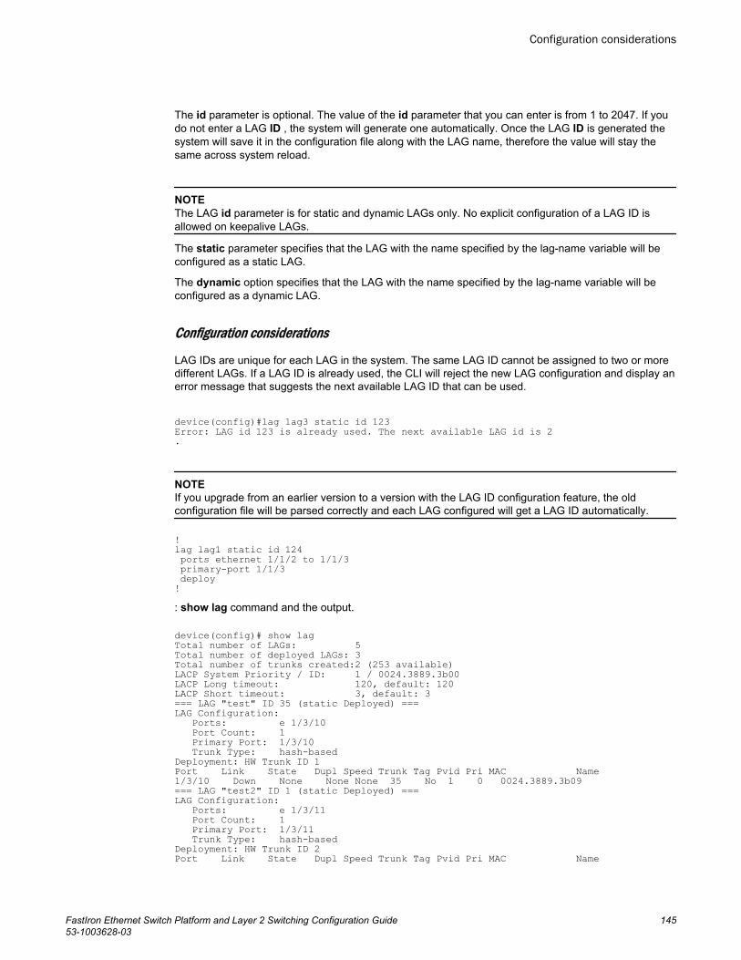
The id parameter is optional. The value of the id parameter that you can enter is from 1 to 2047. If youdo not enter a LAG ID , the system will generate one automatically. Once the LAG ID is generated thesystem will save it in the configuration file along with the LAG name, therefore the value will stay thesame across system reload.
NOTEThe LAG id parameter is for static and dynamic LAGs only. No explicit configuration of a LAG ID isallowed on keepalive LAGs.
The static parameter specifies that the LAG with the name specified by the lag-name variable will beconfigured as a static LAG.
The dynamic option specifies that the LAG with the name specified by the lag-name variable will beconfigured as a dynamic LAG.
Configuration considerations
LAG IDs are unique for each LAG in the system. The same LAG ID cannot be assigned to two or moredifferent LAGs. If a LAG ID is already used, the CLI will reject the new LAG configuration and display anerror message that suggests the next available LAG ID that can be used.
device(config)#lag lag3 static id 123Error: LAG id 123 is already used. The next available LAG id is 2.
NOTEIf you upgrade from an earlier version to a version with the LAG ID configuration feature, the oldconfiguration file will be parsed correctly and each LAG configured will get a LAG ID automatically.
!lag lag1 static id 124 ports ethernet 1/1/2 to 1/1/3 primary-port 1/1/3 deploy!: show lag command and the output.
device(config)# show lagTotal number of LAGs: 5Total number of deployed LAGs: 3Total number of trunks created:2 (253 available)LACP System Priority / ID: 1 / 0024.3889.3b00LACP Long timeout: 120, default: 120LACP Short timeout: 3, default: 3=== LAG "test" ID 35 (static Deployed) ===LAG Configuration: Ports: e 1/3/10 Port Count: 1 Primary Port: 1/3/10 Trunk Type: hash-basedDeployment: HW Trunk ID 1Port Link State Dupl Speed Trunk Tag Pvid Pri MAC Name1/3/10 Down None None None 35 No 1 0 0024.3889.3b09 === LAG "test2" ID 1 (static Deployed) ===LAG Configuration: Ports: e 1/3/11 Port Count: 1 Primary Port: 1/3/11 Trunk Type: hash-basedDeployment: HW Trunk ID 2 Port Link State Dupl Speed Trunk Tag Pvid Pri MAC Name
Configuration considerations
FastIron Ethernet Switch Platform and Layer 2 Switching Configuration Guide 14553-1003628-03
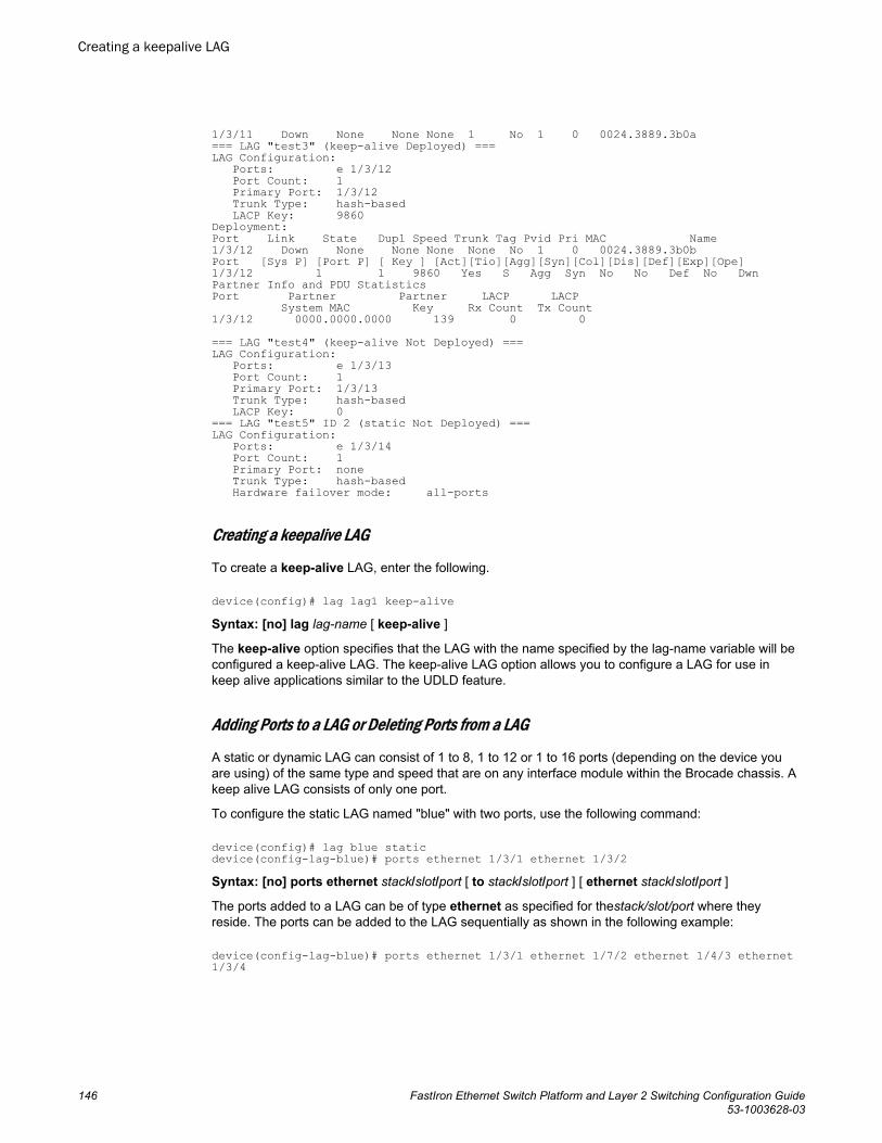
1/3/11 Down None None None 1 No 1 0 0024.3889.3b0a === LAG "test3" (keep-alive Deployed) ===LAG Configuration: Ports: e 1/3/12 Port Count: 1 Primary Port: 1/3/12 Trunk Type: hash-based LACP Key: 9860Deployment:Port Link State Dupl Speed Trunk Tag Pvid Pri MAC Name1/3/12 Down None None None None No 1 0 0024.3889.3b0b Port [Sys P] [Port P] [ Key ] [Act][Tio][Agg][Syn][Col][Dis][Def][Exp][Ope]1/3/12 1 1 9860 Yes S Agg Syn No No Def No DwnPartner Info and PDU Statistics Port Partner Partner LACP LACP System MAC Key Rx Count Tx Count 1/3/12 0000.0000.0000 139 0 0 === LAG "test4" (keep-alive Not Deployed) ===LAG Configuration: Ports: e 1/3/13 Port Count: 1 Primary Port: 1/3/13 Trunk Type: hash-based LACP Key: 0=== LAG "test5" ID 2 (static Not Deployed) ===LAG Configuration: Ports: e 1/3/14 Port Count: 1 Primary Port: none Trunk Type: hash-based Hardware failover mode: all-ports
Creating a keepalive LAG
To create a keep-alive LAG, enter the following.
device(config)# lag lag1 keep-aliveSyntax: [no] lag lag-name [ keep-alive ]
The keep-alive option specifies that the LAG with the name specified by the lag-name variable will beconfigured a keep-alive LAG. The keep-alive LAG option allows you to configure a LAG for use inkeep alive applications similar to the UDLD feature.
Adding Ports to a LAG or Deleting Ports from a LAG
A static or dynamic LAG can consist of 1 to 8, 1 to 12 or 1 to 16 ports (depending on the device youare using) of the same type and speed that are on any interface module within the Brocade chassis. Akeep alive LAG consists of only one port.
To configure the static LAG named "blue" with two ports, use the following command:
device(config)# lag blue staticdevice(config-lag-blue)# ports ethernet 1/3/1 ethernet 1/3/2Syntax: [no] ports ethernet stack/slot/port [ to stack/slot/port ] [ ethernet stack/slot/port ]
The ports added to a LAG can be of type ethernet as specified for thestack/slot/port where theyreside. The ports can be added to the LAG sequentially as shown in the following example:
device(config-lag-blue)# ports ethernet 1/3/1 ethernet 1/7/2 ethernet 1/4/3 ethernet 1/3/4
Creating a keepalive LAG
146 FastIron Ethernet Switch Platform and Layer 2 Switching Configuration Guide53-1003628-03
A range of ports from a single interface module can be specified. In the following example, Ethernetports 1, 2, 3 and 4 on the interface module in slot 3 are configured in a single LAG:
device(config-lag-blue)# ports ethernet 1/3/1 to 1/3/4Additionally, you can mix a range of ports from one interface module with individual ports from otherinterface modules to form a LAG as shown in the following:
device(config-lag-blue)# ports ethernet 1/3/1 to 1/3/4 ethernet 1/2/2Using the no option allows you to remove ports from a LAG. For example, you can remove port 1/3/4from the LAG created above, as shown in the following:
device(config-lag-blue)# no ports ethernet 1/3/4Ports can be added to an undeployed LAG or to currently deployed LAG using the commandsdescribed. For special considerations when adding ports to or deleting ports from a currently deployedLAG, refer to the following sections:
• Adding a Port to Currently Deployed LAG on page 150• Deleting a Port from a Currently Deployed LAG on page 151
Configuring the primary port for a LAG
The primary port must be explicitly assigned using the primary-port command.
To designate the primary port for the static LAG "blue", use the following command.
device(config)# lag blue staticdevice(config-lag-blue)# primary-port 1/3/2Syntax: [no] primary-port stack/slot/port
Once a primary port has been configured for a LAG, all configurations that apply to the primary port areapplied to the other ports in the LAG.
NOTEThis configuration is only applicable for configuration of a static or dynamic LAGs.
Specifying the LAG threshold for a LAG group
You can configure the Brocade device to disable all of the ports in a LAG group when the number ofactive member ports drops below a specified threshold value. When a LAG is shut down because thenumber of ports drops below the configured threshold, the LAG is kept intact and it is re-enabled ifenough ports become active to reach the threshold. For example, if a LAG group has 8 ports, and thethreshold for the LAG group is 5, then the LAG group is disabled if the number of available ports in theLAG group drops below 5. If the LAG group is disabled, then traffic is forwarded over a different link orLAG group.
NOTEThis configuration is only applicable for only the configuration of static LAGs.
For example, the following commands establish a LAG group consisting of 4 ports, then establish athreshold for this LAG group of 3 ports.
device(config)# lag blue static
Configuring the primary port for a LAG
FastIron Ethernet Switch Platform and Layer 2 Switching Configuration Guide 14753-1003628-03
device(config-lag-blue)# ports ethernet 1/3/1 to 1/3/4device(config-lag-blue)# trunk-threshold 3In this example, if the number of active ports drops below 3, then all the ports in the LAG group aredisabled.
Syntax: [no] trunk-threshold number
You can specify a threshold from 1 (the default) up to the number of ports in the LAG group.
When a LAG is shut down because the number of ports drops below the configured threshold, theLAG is kept intact and it is re-enabled if enough ports become active to reach the threshold.
NOTEThe trunk-threshold command should be configured only at one end of the trunk. If it is set on bothsides, link failures will result in race-conditions and the will not function properly.
NOTEThe trunk-threshold command cannot be used in conjunction with protected link groups.
NOTEUse a short LACP timeout when setting the trunk-threshold value equal to the number of links in theLAG or connecting to third party devices. See Configuring an LACP timeout on page 148.
Configuring an LACP timeout
In a dynamic or keep-alive LAG, a port's timeout can be configured as short (3 seconds) or long (90seconds). After you configure a port timeout, the port remains in that timeout mode whether it is up ordown and whether or not it is part of a LAG.
All the ports in a LAG should have the same timeout mode. This requirement is checked when theLAG is enabled on the ports. For example, to configure a port for a short LACP timeout, use thefollowing command.
device(config)# lag blue dynamicdevice(config-lag-blue)# lacp-timeout shortSyntax: [no] lacp-timeout [ long | short ]
To delete the configuration, use the no form of this command.
The long keyword configures the port for the long timeout mode-120 seconds. With the long timeout,an LACPDU is sent every 30 seconds. If no response comes from its partner after 3 LACPDUs aresent, a timeout event occurs, and the LACP state machine transition to the appropriate state based onits current state.
The short keyword configures the port for the short timeout mode--3 seconds. In the short timeoutconfiguration, an LACPDU is sent every second. If no response comes from its partner after 3LACPDUs are sent, a timeout event occurs, and the LACP state machine transitions to the appropriatestate based on its current state.
If you specify neither long nor short , the state machine operates based on the standard IEEEspecification as its default behavior. The original IEEE specification says that the state machine startswith short the timeout and moves to the long timeout after the LAG is established. However,sometimes a vendor’s implementation always uses either the short timeout or the long timeout withoutchanging the timeout. Brocade provides this command so that you can configure Brocade devices tointeroperate with other vendor’s devices.
Configuring an LACP timeout
148 FastIron Ethernet Switch Platform and Layer 2 Switching Configuration Guide53-1003628-03
NOTEThis configuration is applicable to the configuration of dynamic or keep-alive LAGs only.
Deploying a LAG
After configuring a LAG, you must explicitly enable it before it begins aggregating traffic. This task isaccomplished by executing the deploy command within the LAG configuration. After the deploycommand runs, the LAG is in the aggregating mode. Only the primary port within the LAG is available atthe individual interface level. All the secodary ports should have the same IP directed-broadcastconfiguration as the primary port. Any configuration performed on the primary port applies to all portswithin the LAG. The running configuration will no longer display deployed LAG ports other than theprimary port.
To deploy a LAG, at least one port must be in the LAG and the primary port must be specified for nonkeep-alive LAGs. After a non keep-alive LAG is deployed, a LAG is formed. If there is only one port inthe LAG, a single port LAG is formed. For a dynamic LAG, LACP is started for each LAG port. For akeep-alive LAG, no LAG is formed and LACP is started on the LAG port.
You can deploy a LAG as shown in the following for the "blue" LAG.
device(config)# lag blue staticdevice(config-lag-blue)# deploySyntax: [no] deploy [ passive ]
When the deploy command is executed:
For dynamic LAGs, LACP is activated on all LAG ports. When activating LACP, use active mode ifpassive is not specified; otherwise, use passive mode.
For a keep-alive LAGs, no LAG is formed, and LACP is started on the LAG port.
Once the deploy command is issued, all LAG ports will behave like a single port.
If the no deploy command is executed, the LAG is removed. For dynamic LAGs, LACP is de-activatedon all of the LAG ports. All the secondary ports are disabled automatically and there will be no changesto the primary port.
Commands available under LAG once it is deployedOnce a LAG has been deployed, the following configurations can be performed on the deployed LAG:
• Disabling Ports within a LAG• Enabling Ports within a LAG• Monitoring and Individual LAG Port• Assigning a name to a port within a LAG• Enabling sFlow Forwarding on a port within a LAG• Setting the sFlow Sampling Rate for a port within a LAG• IP assignment within a LAG• Renaming an existing LAG
Deploying a LAG
FastIron Ethernet Switch Platform and Layer 2 Switching Configuration Guide 14953-1003628-03
Disabling ports within a LAGYou can disable an individual port within a LAG using the disable command within the LAGconfiguration as shown in the following.
device(config)# lag blue staticdevice(config-lag-blue)# disable ethernet 1/3/1Syntax: [no] disable { ethernet stack/slot/port [ to stack/slot/port ] [ ethernet stack/slot/port ] | port-name name }
Use the ethernet option with the appropriate stack/slot/port variable to specify a Ethernet port withinthe LAG that you want to disable.
Use the port-name option with the appropriate name variable to specify a named port within the LAGthat you want to disable.
To disable a port belonging to a keep-alive LAG, you need to configure from the interface level.
Brocade(config-lag-test)#interface e 1/7/8Brocade(config-if-e1000-1/7/8)#disableBrocade(config-if-e1000-1/7/8)#
Enabling ports within a LAGYou can enable an individual port within a LAG using the enable command within the LAGconfiguration as shown in the following.
device(config)# lag blue staticdevice(config-lag-blue)# deploydevice(config-lag-blue)# enable ethernet 1/3/1Syntax: [no] enable { ethernet stack/slot/port [ to stack/slot/port ] [ ethernet stack/slot/port ] | port-name name }
Use the ethernet option with the appropriate stack/slot/port variable to specify a Ethernet port withinthe LAG that you want to enable.
Use the port-name option with the appropriate name variable to specify a named port within the LAGthat you want to enable.
To enable a port belonging to a keep-alive LAG, you need to configure from the interface level.
Brocade(config-lag-test)#interface e 1/7/8Brocade(config-if-e1000-1/7/8)#enableBrocade(config-if-e1000-1/7/8)#
Adding a Port to Currently Deployed LAGPorts can be added to a currently deployed LAG. Adding a port to a deployed LAG uses the sameprocedures as described in Adding Ports to a LAG or Deleting Ports from a LAG on page 146. Whenyou add ports to a deployed LAG, the MAC address of the port being added is changed to that of theprimary port of the LAG to which it is being added.
When you add a new secondary port to a currently deployed LAG, the IP directed-broadcastconfiguration and all other configuration of the new port should be the same as that of the primary portof the LAG.
Disabling ports within a LAG
150 FastIron Ethernet Switch Platform and Layer 2 Switching Configuration Guide53-1003628-03
NOTEIn an operational dynamic LAG, adding or removing a port causes port flapping for all LAG ports. Thismay cause loss of traffic.
Deleting a Port from a Currently Deployed LAGPorts can be deleted from a currently deployed LAG. Deleting a port in a currently deployed LAG usesthe same procedures as described in Adding Ports to a LAG or Deleting Ports from a LAG on page 146.However, when deleting ports from a currently deployed LAG you must consider the following:
• The primary port cannot be removed.• If removal of a port will result in the trunk threshold value becoming greater than the number of ports
in the LAG, the port deletion will be rejected.• When you remove a port from a deployed LAG, the port is disabled automatically.
To delete port 1/3/1 which is in the "enabled" state from a currently deployed LAG named "blue", usethe following command:
device(config)# lag blue staticdevice(config-lag-blue)# no ports ethernet 1/3/1 Syntax: [no] ports ethernet stack/slot/port [ to stack/slot/port ] [ ethernet stack/slot/port ]
NOTEWhen a port is deleted from a currently deployed LAG, the MAC address of the port is changed back toits original value.
NOTEIn an operational dynamic LAG, removing an operational port causes port flapping for all LAG ports.This may cause loss of traffic.
Monitoring an individual LAG portBy default, when you monitor the primary port in a LAG group, aggregated traffic for all the ports in theLAG is copied to the mirror port. You can configure the device to monitor individual ports in a LAGincluding Ethernet, or named ports. You can monitor the primary port or another member portindividually. Once a LAG is deployed and a primary port is specified using the primary-port command,monitoring across all ports of the LAG can be configured at the primary port. If a new port is added to adeployed LAG and if the entire LAG is monitored, the new port will also be mirrored by the same portmonitoring traffic across the entire LAG.
NOTEYou can use only one mirror port for each monitored LAG port. You cannot configure mirroring on anundeployed LAG.
To monitor traffic on an individual port in a LAG group, run the following commands.
device(config)# lag blue staticdevice(config-lag-blue)# ports ethernet 1/1/1 ethernet 1/1/47device(config-lag-blue)# primary-port 1/1/1
Deleting a Port from a Currently Deployed LAG
FastIron Ethernet Switch Platform and Layer 2 Switching Configuration Guide 15153-1003628-03
device(config-lag-blue)# deploydevice(config-lag-blue)# monitor ethe-port-monitored 1/1/47 ethernet 1/1/15 outputSyntax: [no] monitor { ethe-port-monitored stack/ slot / port | named-port-monitored name } [ethernet [ stack/ slot / port ] ] { input | output | both }
Use the ethe-port-monitored option with the appropriate [stack/slot/port] variable to specify aEthernet port within the LAG that you want to monitor.
Use the named-port-monitored option with the appropriate name variable to specify a named portwithin the LAG that you want monitor.
The ethernet stack/slot/port parameter specifies the port to which the traffic analyzer is attached.
The input, output, and both parameters specify the traffic direction to be monitored.
Assigning a name to a port within a LAGYou can assign a name to an individual port within a LAG using the port-name command within theLAG configuration as shown in the following.
device(config)#lag "test" dynamic id 1device(config-lag-test)#ports ethernet 1/1/1 to 1/1/3device(config-lag-test)#port-name "Brocade lag" ethernet 1/1/1device(config-lag-test)#primary-port 1/1/1device(config-lag-test)#deploy Syntax: [no] port-name name ethernet stack/slot/port
The name variable specifies the port name. The name can be up to 255 characters long.
NOTEPort name with space must be enclosed within double quotation marks.
Use the ethernet option with the appropriate stack/slot/port variable to apply the specified name to anEthernet port within the LAG.
Allowable characters for LAG names
When creating a LAG name, you can use spaces in a file or subdirectory name if you enclose thename in double quotes. For example, to specify a subdirectory name that contains spaces, enter astring such as the following: "a long subdirectory name". The maximum length for a string is 64characters.
The following characters are valid in file names:
• All upper and lowercase letters• All digits
Any of the following special characters are valid:
• $• %• '• -• _• .• @• ~
Assigning a name to a port within a LAG
152 FastIron Ethernet Switch Platform and Layer 2 Switching Configuration Guide53-1003628-03
• `• !• (• )• {• }• ^• #• &
Enabling sFlow forwarding on a port in a LAGYou can enable sFlow forwarding on an individual port within a LAG using the sflow-forwardingcommand within the LAG configuration as shown in the following.
device(config)# lag blue staticdevice(config-lag-blue)# deploydevice(config-lag-blue)# sflow forwarding ethernet 1/3/1Syntax: [no] sflow forwarding { ethernet stack/slot/port | port-name name }
Use the ethernet option with the appropriate stack/slot/port variable to specify a Ethernet port within theLAG that you want to enable sFlow forwarding for.
Use the port-name option with the appropriate name variable to specify a named port within the LAGthat you want to enable sFlow forwarding for.
For a keep-alive LAG, sFlow can be enabled only at the interface level and not at a lag context. Toconfigure sFLow for an interface belonging to the keep-alive lag, configure directly under the interface.
Brocade(config-lag-test)#interface e 1/7/8Brocade(config-if-e1000-1/7/8)#sflow forwardingBrocade(config-if-e1000-1/7/8)#
Setting the sFlow sampling rate for a port in a LAGYou can set the sFlow sampling rate for an individual port within a LAG using the sflow-subsamplingcommand within the LAG configuration as shown in the following.
device(config)# lag blue staticdevice(config-lag-blue)# deploydevice(config-lag-blue)# sflow sample 512Syntax: [no] sflow sample number
The number variable specifies the average number of packets from which each sample will be taken.The software rounds the value you enter up to the next odd power of 2. This can be a value between 8 -1048576.
For a keep-alive LAG, you need to configure sFlow sampling at the interface level and not within theLAG configuration.
Brocade(config-lag-test)#interface e 1/7/8Brocade(config-if-e1000-1/7/8)#sflow sample 512Brocade(config-if-e1000-1/7/8)#
Enabling sFlow forwarding on a port in a LAG
FastIron Ethernet Switch Platform and Layer 2 Switching Configuration Guide 15353-1003628-03
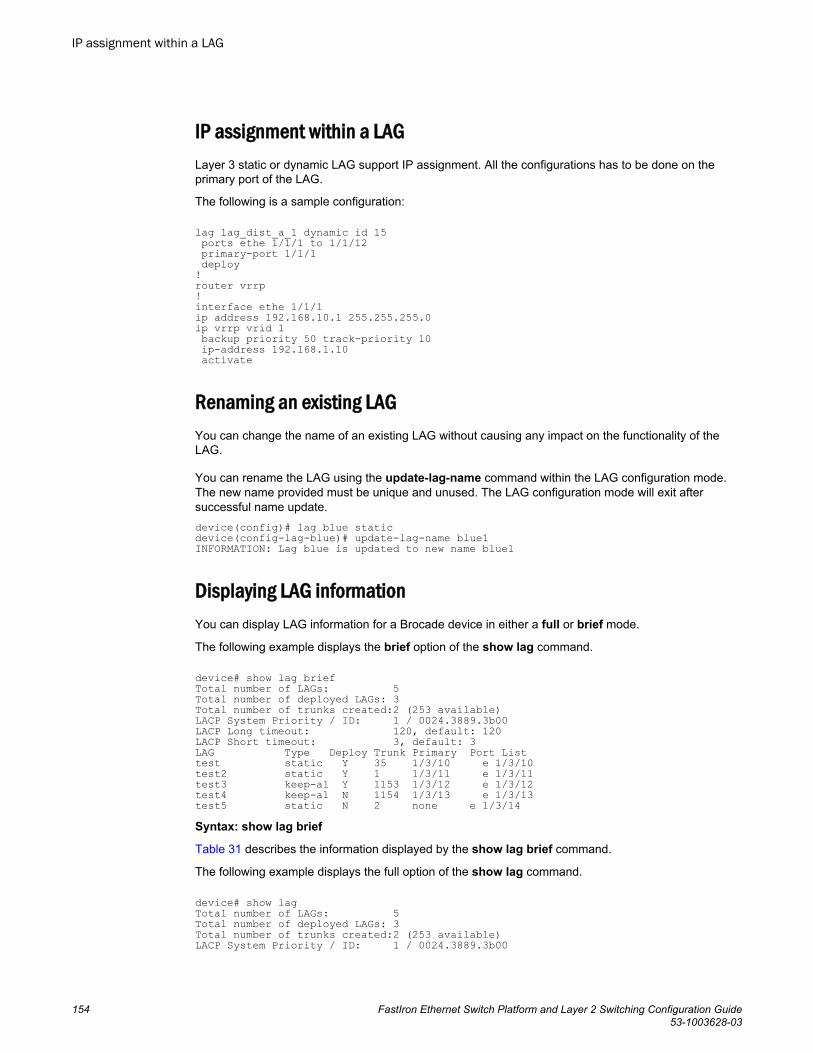
IP assignment within a LAGLayer 3 static or dynamic LAG support IP assignment. All the configurations has to be done on theprimary port of the LAG.
The following is a sample configuration:
lag lag_dist_a_1 dynamic id 15 ports ethe 1/1/1 to 1/1/12 primary-port 1/1/1 deploy!router vrrp!interface ethe 1/1/1ip address 192.168.10.1 255.255.255.0ip vrrp vrid 1 backup priority 50 track-priority 10 ip-address 192.168.1.10 activate
Renaming an existing LAGYou can change the name of an existing LAG without causing any impact on the functionality of theLAG.
You can rename the LAG using the update-lag-name command within the LAG configuration mode.The new name provided must be unique and unused. The LAG configuration mode will exit aftersuccessful name update.device(config)# lag blue staticdevice(config-lag-blue)# update-lag-name blue1INFORMATION: Lag blue is updated to new name blue1
Displaying LAG informationYou can display LAG information for a Brocade device in either a full or brief mode.
The following example displays the brief option of the show lag command.
device# show lag briefTotal number of LAGs: 5Total number of deployed LAGs: 3Total number of trunks created:2 (253 available)LACP System Priority / ID: 1 / 0024.3889.3b00LACP Long timeout: 120, default: 120LACP Short timeout: 3, default: 3LAG Type Deploy Trunk Primary Port Listtest static Y 35 1/3/10 e 1/3/10 test2 static Y 1 1/3/11 e 1/3/11 test3 keep-al Y 1153 1/3/12 e 1/3/12 test4 keep-al N 1154 1/3/13 e 1/3/13 test5 static N 2 none e 1/3/14Syntax: show lag brief
Table 31 describes the information displayed by the show lag brief command.
The following example displays the full option of the show lag command.
device# show lagTotal number of LAGs: 5Total number of deployed LAGs: 3Total number of trunks created:2 (253 available)LACP System Priority / ID: 1 / 0024.3889.3b00
IP assignment within a LAG
154 FastIron Ethernet Switch Platform and Layer 2 Switching Configuration Guide53-1003628-03
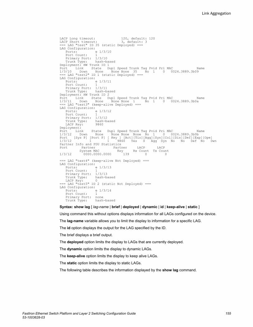
LACP Long timeout: 120, default: 120LACP Short timeout: 3, default: 3=== LAG "test" ID 35 (static Deployed) ===LAG Configuration: Ports: e 1/3/10 Port Count: 1 Primary Port: 1/3/10 Trunk Type: hash-basedDeployment: HW Trunk ID 1Port Link State Dupl Speed Trunk Tag Pvid Pri MAC Name1/3/10 Down None None None 35 No 1 0 0024.3889.3b09 === LAG "test2" ID 1 (static Deployed) ===LAG Configuration: Ports: e 1/3/11 Port Count: 1 Primary Port: 1/3/11 Trunk Type: hash-basedDeployment: HW Trunk ID 2 Port Link State Dupl Speed Trunk Tag Pvid Pri MAC Name1/3/11 Down None None None 1 No 1 0 0024.3889.3b0a === LAG "test3" (keep-alive Deployed) ===LAG Configuration: Ports: e 1/3/12 Port Count: 1 Primary Port: 1/3/12 Trunk Type: hash-based LACP Key: 9860Deployment:Port Link State Dupl Speed Trunk Tag Pvid Pri MAC Name1/3/12 Down None None None None No 1 0 0024.3889.3b0b Port [Sys P] [Port P] [ Key ] [Act][Tio][Agg][Syn][Col][Dis][Def][Exp][Ope]1/3/12 1 1 9860 Yes S Agg Syn No No Def No DwnPartner Info and PDU Statistics Port Partner Partner LACP LACP System MAC Key Rx Count Tx Count 1/3/12 0000.0000.0000 139 0 0 === LAG "test4" (keep-alive Not Deployed) ===LAG Configuration: Ports: e 1/3/13 Port Count: 1 Primary Port: 1/3/13 Trunk Type: hash-based LACP Key: 0=== LAG "test5" ID 2 (static Not Deployed) ===LAG Configuration: Ports: e 1/3/14 Port Count: 1 Primary Port: none Trunk Type: hash-basedSyntax: show lag [ lag-name | brief | deployed | dynamic | id | keep-alive | static ]
Using command this without options displays information for all LAGs configured on the device.
The lag-name variable allows you to limit the display to information for a specific LAG.
The id option displays the output for the LAG specified by the ID.
The brief displays a brief output.
The deployed option limits the display to LAGs that are currently deployed.
The dynamic option limits the display to dynamic LAGs.
The keep-alive option limits the display to keep alive LAGs.
The static option limits the display to static LAGs.
The following table describes the information displayed by the show lag command.
Link Aggregation
FastIron Ethernet Switch Platform and Layer 2 Switching Configuration Guide 15553-1003628-03
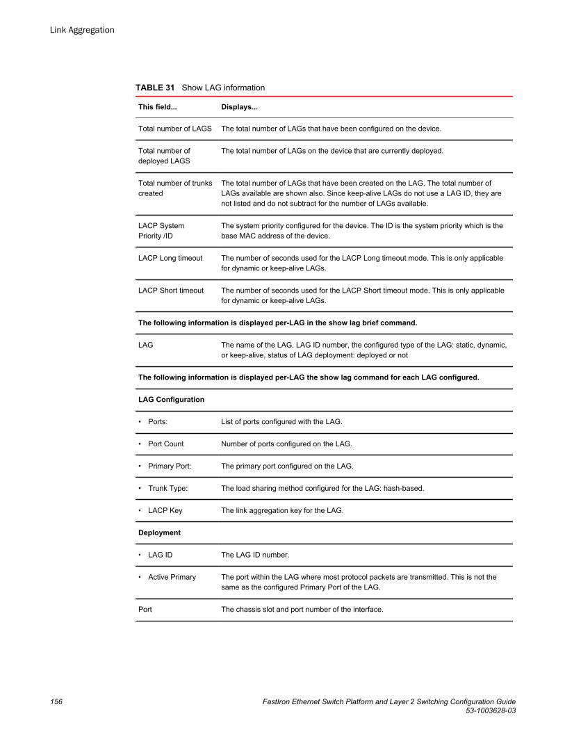
Show LAG information TABLE 31
This field... Displays...
Total number of LAGS The total number of LAGs that have been configured on the device.
Total number ofdeployed LAGS
The total number of LAGs on the device that are currently deployed.
Total number of trunkscreated
The total number of LAGs that have been created on the LAG. The total number ofLAGs available are shown also. Since keep-alive LAGs do not use a LAG ID, they arenot listed and do not subtract for the number of LAGs available.
LACP SystemPriority /ID
The system priority configured for the device. The ID is the system priority which is thebase MAC address of the device.
LACP Long timeout The number of seconds used for the LACP Long timeout mode. This is only applicablefor dynamic or keep-alive LAGs.
LACP Short timeout The number of seconds used for the LACP Short timeout mode. This is only applicablefor dynamic or keep-alive LAGs.
The following information is displayed per-LAG in the show lag brief command.
LAG The name of the LAG, LAG ID number, the configured type of the LAG: static, dynamic,or keep-alive, status of LAG deployment: deployed or not
The following information is displayed per-LAG the show lag command for each LAG configured.
LAG Configuration
• Ports: List of ports configured with the LAG.
• Port Count Number of ports configured on the LAG.
• Primary Port: The primary port configured on the LAG.
• Trunk Type: The load sharing method configured for the LAG: hash-based.
• LACP Key The link aggregation key for the LAG.
Deployment
• LAG ID The LAG ID number.
• Active Primary The port within the LAG where most protocol packets are transmitted. This is not thesame as the configured Primary Port of the LAG.
Port The chassis slot and port number of the interface.
Link Aggregation
156 FastIron Ethernet Switch Platform and Layer 2 Switching Configuration Guide53-1003628-03
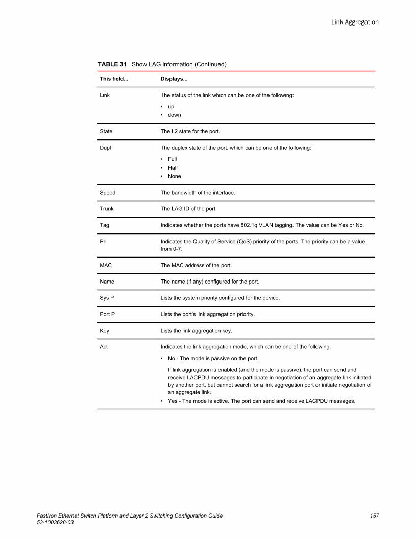
Show LAG information (Continued)TABLE 31
This field... Displays...
Link The status of the link which can be one of the following:
• up• down
State The L2 state for the port.
Dupl The duplex state of the port, which can be one of the following:
• Full• Half• None
Speed The bandwidth of the interface.
Trunk The LAG ID of the port.
Tag Indicates whether the ports have 802.1q VLAN tagging. The value can be Yes or No.
Pri Indicates the Quality of Service (QoS) priority of the ports. The priority can be a valuefrom 0-7.
MAC The MAC address of the port.
Name The name (if any) configured for the port.
Sys P Lists the system priority configured for the device.
Port P Lists the port’s link aggregation priority.
Key Lists the link aggregation key.
Act Indicates the link aggregation mode, which can be one of the following:
• No - The mode is passive on the port.
If link aggregation is enabled (and the mode is passive), the port can send andreceive LACPDU messages to participate in negotiation of an aggregate link initiatedby another port, but cannot search for a link aggregation port or initiate negotiation ofan aggregate link.
• Yes - The mode is active. The port can send and receive LACPDU messages.
Link Aggregation
FastIron Ethernet Switch Platform and Layer 2 Switching Configuration Guide 15753-1003628-03
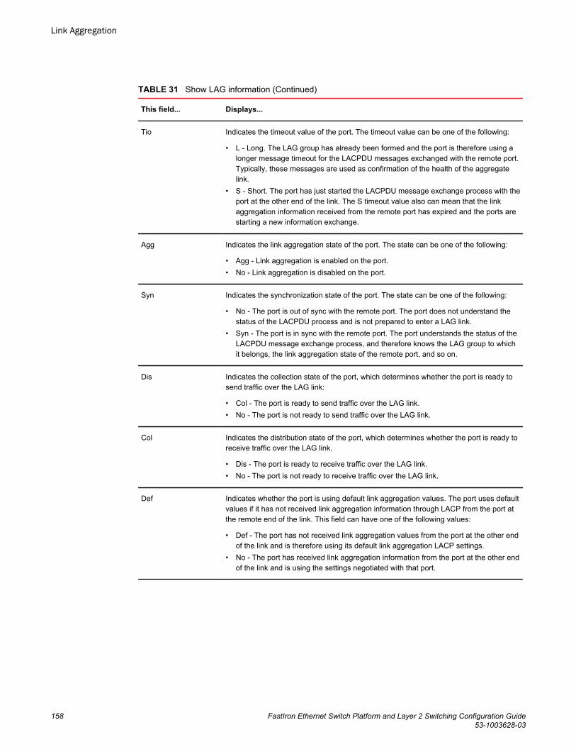
Show LAG information (Continued)TABLE 31
This field... Displays...
Tio Indicates the timeout value of the port. The timeout value can be one of the following:
• L - Long. The LAG group has already been formed and the port is therefore using alonger message timeout for the LACPDU messages exchanged with the remote port.Typically, these messages are used as confirmation of the health of the aggregatelink.
• S - Short. The port has just started the LACPDU message exchange process with theport at the other end of the link. The S timeout value also can mean that the linkaggregation information received from the remote port has expired and the ports arestarting a new information exchange.
Agg Indicates the link aggregation state of the port. The state can be one of the following:
• Agg - Link aggregation is enabled on the port.• No - Link aggregation is disabled on the port.
Syn Indicates the synchronization state of the port. The state can be one of the following:
• No - The port is out of sync with the remote port. The port does not understand thestatus of the LACPDU process and is not prepared to enter a LAG link.
• Syn - The port is in sync with the remote port. The port understands the status of theLACPDU message exchange process, and therefore knows the LAG group to whichit belongs, the link aggregation state of the remote port, and so on.
Dis Indicates the collection state of the port, which determines whether the port is ready tosend traffic over the LAG link:
• Col - The port is ready to send traffic over the LAG link.• No - The port is not ready to send traffic over the LAG link.
Col Indicates the distribution state of the port, which determines whether the port is ready toreceive traffic over the LAG link.
• Dis - The port is ready to receive traffic over the LAG link.• No - The port is not ready to receive traffic over the LAG link.
Def Indicates whether the port is using default link aggregation values. The port uses defaultvalues if it has not received link aggregation information through LACP from the port atthe remote end of the link. This field can have one of the following values:
• Def - The port has not received link aggregation values from the port at the other endof the link and is therefore using its default link aggregation LACP settings.
• No - The port has received link aggregation information from the port at the other endof the link and is using the settings negotiated with that port.
Link Aggregation
158 FastIron Ethernet Switch Platform and Layer 2 Switching Configuration Guide53-1003628-03
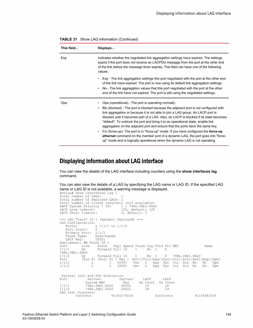
Show LAG information (Continued)TABLE 31
This field... Displays...
Exp Indicates whether the negotiated link aggregation settings have expired. The settingsexpire if the port does not receive an LACPDU message from the port at the other endof the link before the message timer expires. This field can have one of the followingvalues:
• Exp - The link aggregation settings this port negotiated with the port at the other endof the link have expired. The port is now using its default link aggregation settings.
• No - The link aggregation values that this port negotiated with the port at the otherend of the link have not expired. The port is still using the negotiated settings.
Ope • Ope (operational) - The port is operating normally.• Blo (blocked) - The port is blocked because the adjacent port is not configured with
link aggregation or because it is not able to join a LAG group. An LACP port isblocked until it becomes part of a LAG. Also, an LACP is blocked if its state becomes"default". To unblock the port and bring it to an operational state, enable linkaggregation on the adjacent port and ensure that the ports have the same key.
• Frc (force-up)- The port is in "force-up" mode. If you have configured the force-upethernet command on the member port of a dynamic LAG, the port goes into "force-up" mode and is logically operational when the dynamic LAG is not operating.
Displaying information about LAG interfaceYou can view the details of the LAG interface including counters using the show interfaces lagcommand.
You can also view the details of a LAG by specifying the LAG name or LAG ID. If the specified LAGname or LAG ID is not available, a warning message is displayed.device# show interfaces lag 1Total number of LAGs: 1Total number of deployed LAGs: 1Total number of trunks created:1 (123 available)LACP System Priority / ID: 1 / 748e.f8b1.66e0LACP Long timeout: 120, default: 120LACP Short timeout: 3, default: 3=== LAG "test" ID 1 (dynamic Deployed) ===LAG Configuration: Ports: e 1/1/1 to 1/1/2 Port Count: 2 Primary Port: 1/1/1 Trunk Type: hash-based LACP Key: 20001Deployment: HW Trunk ID 1Port Link State Dupl Speed Trunk Tag Pvid Pri MAC Name1/1/1 Up Forward Full 1G 1 No 1 0 748e.f8b1.66e0 1/1/2 Up Forward Full 1G 1 No 1 0 748e.f8b1.66e0Port [Sys P] [Port P] [ Key ] [Act][Tio][Agg][Syn][Col][Dis][Def][Exp][Ope]1/1/1 1 1 20001 Yes L Agg Syn Col Dis No No Ope1/1/2 1 1 20001 Yes L Agg Syn Col Dis No No Ope
Partner Info and PDU Statistics Port Partner Partner LACP LACP System MAC Key Rx Count Tx Count 1/1/1 748e.f8b1.6020 20001 19 181/1/2 748e.f8b1.6020 20001 18 19LAG test Counters: InOctets 91162279156 OutOctets 91155682034
Displaying information about LAG interface
FastIron Ethernet Switch Platform and Layer 2 Switching Configuration Guide 15953-1003628-03
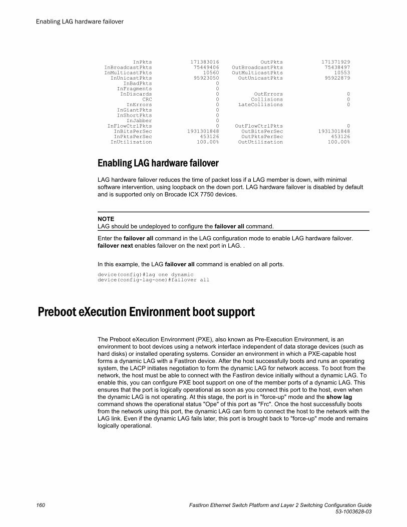
InPkts 171383016 OutPkts 171371929 InBroadcastPkts 75449406 OutBroadcastPkts 75438497 InMulticastPkts 10560 OutMulticastPkts 10553 InUnicastPkts 95923050 OutUnicastPkts 95922879 InBadPkts 0 InFragments 0 InDiscards 0 OutErrors 0 CRC 0 Collisions 0 InErrors 0 LateCollisions 0 InGiantPkts 0 InShortPkts 0 InJabber 0 InFlowCtrlPkts 0 OutFlowCtrlPkts 0 InBitsPerSec 1931301848 OutBitsPerSec 1931301848 InPktsPerSec 453126 OutPktsPerSec 453126 InUtilization 100.00% OutUtilization 100.00%
Enabling LAG hardware failoverLAG hardware failover reduces the time of packet loss if a LAG member is down, with minimalsoftware intervention, using loopback on the down port. LAG hardware failover is disabled by defaultand is supported only on Brocade ICX 7750 devices.
NOTELAG should be undeployed to configure the failover all command.
Enter the failover all command in the LAG configuration mode to enable LAG hardware failover.failover next enables failover on the next port in LAG. .
In this example, the LAG failover all command is enabled on all ports.device(config)#lag one dynamic device(config-lag-one)#failover all
Preboot eXecution Environment boot support
The Preboot eXecution Environment (PXE), also known as Pre-Execution Environment, is anenvironment to boot devices using a network interface independent of data storage devices (such ashard disks) or installed operating systems. Consider an environment in which a PXE-capable hostforms a dynamic LAG with a FastIron device. After the host successfully boots and runs an operatingsystem, the LACP initiates negotiation to form the dynamic LAG for network access. To boot from thenetwork, the host must be able to connect with the FastIron device initially without a dynamic LAG. Toenable this, you can configure PXE boot support on one of the member ports of a dynamic LAG. Thisensures that the port is logically operational as soon as you connect this port to the host, even whenthe dynamic LAG is not operating. At this stage, the port is in "force-up" mode and the show lagcommand shows the operational status "Ope" of this port as "Frc". Once the host successfully bootsfrom the network using this port, the dynamic LAG can form to connect the host to the network with theLAG link. Even if the dynamic LAG fails later, this port is brought back to "force-up" mode and remainslogically operational.
Enabling LAG hardware failover
160 FastIron Ethernet Switch Platform and Layer 2 Switching Configuration Guide53-1003628-03
Enabling PXE boot support on a port
• The port should be an edge port on which you have not configured protocols such as STP, MRP, andUDLD.
• The dynamic LAG should be in an undeployed state.
You can configure the member port of a dynamic LAG to be logically operational even when thedynamic LAG is not operating. This enables PXE boot support on this port.
NOTEYou can enable PXE boot support on only one member port of a dynamic LAG.
Run the force-up ethernet command in dynamic LAG configuration mode.
The following example shows PXE boot support enabled on member port 3/1/1 of a dynamic LAG R4-dyn.Brocade(config)# lag R4-dynBrocade(config-lag-R4-dyn)# force-up ethernet 3/1/1
User-configured peer information per LACPBrocade FastIron devices allow users to define their desired peers under the dynamic LAGconfiguration if they do not want the default first LACP trunk port to be defined as the LAG’s peerinformation record.
In certain cases, when ports of one dynamic LAG are connected to two different LACP peers (differentsystem IDs, or same system ID with different key values), the device forms one LACP trunk perdynamic LAG and the other port is moved to the error disabled state. In a dynamic LAG, each memberport stores a record of its peer’s LACP information (system priority, system ID, and system key) fromthe latest LACPDU it received. This information is known as the port’s peer information record. Becauseall member ports of an LACP trunk share the same local and peer information, the dynamic LAG's peerinformation record can be any one of its unique LACP trunk port’s peer information record (systempriority, system ID, or system key). If a dynamic LAG has no associated LACP trunk, its peerinformation record is stored as NULL.
The peer-info command is used to configure the peer system ID and system key for a single dynamicLAG.
NOTEWhen there is no user configuration, the system makes sure there is only one LACP trunk within onedynamic LAG. It allows the first LACP trunk port’s LACP peer information record to be defined as theLAG’s peer information record.
NOTERun the show lag command to view information about the LACP peer's partner system ID (priority andMAC address) and partner system key.
Enabling PXE boot support on a port
FastIron Ethernet Switch Platform and Layer 2 Switching Configuration Guide 16153-1003628-03
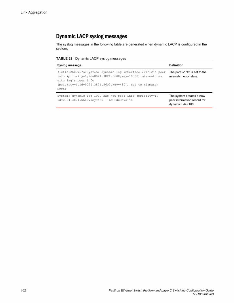
Dynamic LACP syslog messagesThe syslog messages in the following table are generated when dynamic LACP is configured in thesystem.
Dynamic LACP syslog messagesTABLE 32
Syslog message Definition
<14>1d12h07m57s:System: dynamic lag interface 2/1/12's peerinfo (priority=1,id=0024.3821.5600,key=10000) mis-matcheswith lag's peer info(priority=1,id=0024.3821.5600,key=480), set to mismatchError
The port 2/1/12 is set to themismatch error state.
System: dynamic lag 100, has new peer info (priority=1,id=0024.3821.5600,key=480) (LACPduRcvd)\n
The system creates a newpeer information record fordynamic LAG 100.
Link Aggregation
162 FastIron Ethernet Switch Platform and Layer 2 Switching Configuration Guide53-1003628-03
Multi-Chassis Trunking
● Multi-Chassis Trunking Overview..................................................................................163● Layer 2 behavior with MCT........................................................................................... 179● Displaying MCT information.......................................................................................... 188● MCT configuration examples ....................................................................................... 193
Multi-Chassis Trunking OverviewMulti-Chassis Trunking (MCT) is an alternative to spanning tree protocols. Spanning tree is atechnology that protects the network against loops by blocking necessary ports, and having the networkspan to relearn topologies when one link fails in a network. MCT is a technology that allows two MCT-supporting switches to cluster together and appear as a single logical device. Trunking is a technologythat allows multiple links of a device to appear as one logical link. The combination of MCT and trunkingallows for creating a resilient network topology that utilizes all links in the network, creating an idealnetwork topology for latency sensitive applications.
Standard static or dynamic LACP trunks provide link-level redundancy and increased capacity.However, trunks do not provide device-level redundancy. If the device to which the trunk is attachedfails, the entire trunk loses network connectivity. Two devices are needed for network resiliency withtrunked links to both devices. With spanning tree, one of these trunks would be blocked from use untilthe failure of the other trunk is detected, taking from 1 to 30 seconds potentially adding latency andjitter, not only on the affected devices locally, but throughout the span topology. With MCT, memberlinks of the trunk are split and connected to two clustered MCT-supporting switches. MCT hasintegrated loop detections, which allows all links to be active. If a failure is detected, traffic isdynamically allocated across the remaining links. The failure detection and allocation of traffic occur insub-second time, without impact on the rest of the network.
MCT inherits all of the benefits of a trunk group and allows multiple physical links to act as a singlelogical link. The resulting available bandwidth is an aggregate of all the links in the group. Traffic isshared across the links in the group using dynamic flow-based load balancing, and traffic is moved to aremaining link group in sub-seconds if a failure occurs on one of the links. MCT eliminates the singlepoint of failure that exists at the device level when all links of a trunk terminate on the same devicewithout the overhead associated with spanning tree. MCT diverts a subset of the links to a seconddevice to provide redundancy and sub-second fault detection at the device level.
How MCT worksThe following table shows a basic MCT configuration. The MCT originates at a single MCT-unawareserver or switch and terminates at two MCT-aware devices.
FastIron Ethernet Switch Platform and Layer 2 Switching Configuration Guide 16353-1003628-03
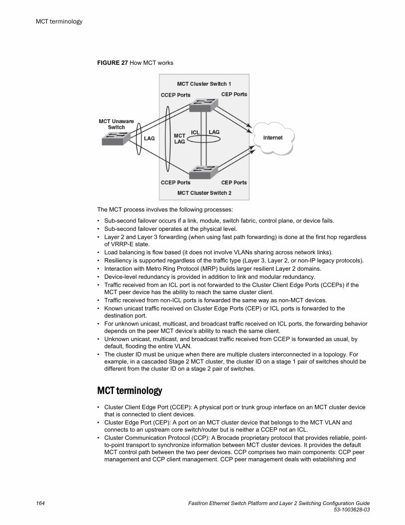
FIGURE 27 How MCT works
The MCT process involves the following processes:
• Sub-second failover occurs if a link, module, switch fabric, control plane, or device fails.• Sub-second failover operates at the physical level.• Layer 2 and Layer 3 forwarding (when using fast path forwarding) is done at the first hop regardless
of VRRP-E state.• Load balancing is flow based (it does not involve VLANs sharing across network links).• Resiliency is supported regardless of the traffic type (Layer 3, Layer 2, or non-IP legacy protocols).• Interaction with Metro Ring Protocol (MRP) builds larger resilient Layer 2 domains.• Device-level redundancy is provided in addition to link and modular redundancy.• Traffic received from an ICL port is not forwarded to the Cluster Client Edge Ports (CCEPs) if the
MCT peer device has the ability to reach the same cluster client.• Traffic received from non-ICL ports is forwarded the same way as non-MCT devices.• Known unicast traffic received on Cluster Edge Ports (CEP) or ICL ports is forwarded to the
destination port.• For unknown unicast, multicast, and broadcast traffic received on ICL ports, the forwarding behavior
depends on the peer MCT device’s ability to reach the same client.• Unknown unicast, multicast, and broadcast traffic received from CCEP is forwarded as usual, by
default, flooding the entire VLAN.• The cluster ID must be unique when there are multiple clusters interconnected in a topology. For
example, in a cascaded Stage 2 MCT cluster, the cluster ID on a stage 1 pair of switches should bedifferent from the cluster ID on a stage 2 pair of switches.
MCT terminology• Cluster Client Edge Port (CCEP): A physical port or trunk group interface on an MCT cluster device
that is connected to client devices.• Cluster Edge Port (CEP): A port on an MCT cluster device that belongs to the MCT VLAN and
connects to an upstream core switch/router but is neither a CCEP not an ICL.• Cluster Communication Protocol (CCP): A Brocade proprietary protocol that provides reliable, point-
to-point transport to synchronize information between MCT cluster devices. It provides the defaultMCT control path between the two peer devices. CCP comprises two main components: CCP peermanagement and CCP client management. CCP peer management deals with establishing and
MCT terminology
164 FastIron Ethernet Switch Platform and Layer 2 Switching Configuration Guide53-1003628-03
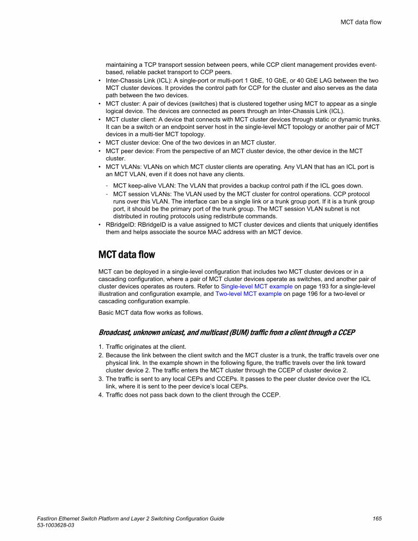
maintaining a TCP transport session between peers, while CCP client management provides event-based, reliable packet transport to CCP peers.
• Inter-Chassis Link (ICL): A single-port or multi-port 1 GbE, 10 GbE, or 40 GbE LAG between the twoMCT cluster devices. It provides the control path for CCP for the cluster and also serves as the datapath between the two devices.
• MCT cluster: A pair of devices (switches) that is clustered together using MCT to appear as a singlelogical device. The devices are connected as peers through an Inter-Chassis Link (ICL).
• MCT cluster client: A device that connects with MCT cluster devices through static or dynamic trunks.It can be a switch or an endpoint server host in the single-level MCT topology or another pair of MCTdevices in a multi-tier MCT topology.
• MCT cluster device: One of the two devices in an MCT cluster.• MCT peer device: From the perspective of an MCT cluster device, the other device in the MCT
cluster.• MCT VLANs: VLANs on which MCT cluster clients are operating. Any VLAN that has an ICL port is
an MCT VLAN, even if it does not have any clients.
‐ MCT keep-alive VLAN: The VLAN that provides a backup control path if the ICL goes down.‐ MCT session VLANs: The VLAN used by the MCT cluster for control operations. CCP protocol
runs over this VLAN. The interface can be a single link or a trunk group port. If it is a trunk groupport, it should be the primary port of the trunk group. The MCT session VLAN subnet is notdistributed in routing protocols using redistribute commands.
• RBridgeID: RBridgeID is a value assigned to MCT cluster devices and clients that uniquely identifiesthem and helps associate the source MAC address with an MCT device.
MCT data flowMCT can be deployed in a single-level configuration that includes two MCT cluster devices or in acascading configuration, where a pair of MCT cluster devices operate as switches, and another pair ofcluster devices operates as routers. Refer to Single-level MCT example on page 193 for a single-levelillustration and configuration example, and Two-level MCT example on page 196 for a two-level orcascading configuration example.
Basic MCT data flow works as follows.
Broadcast, unknown unicast, and multicast (BUM) traffic from a client through a CCEP1. Traffic originates at the client.2. Because the link between the client switch and the MCT cluster is a trunk, the traffic travels over one
physical link. In the example shown in the following figure, the traffic travels over the link towardcluster device 2. The traffic enters the MCT cluster through the CCEP of cluster device 2.
3. The traffic is sent to any local CEPs and CCEPs. It passes to the peer cluster device over the ICLlink, where it is sent to the peer device’s local CEPs.
4. Traffic does not pass back down to the client through the CCEP.
MCT data flow
FastIron Ethernet Switch Platform and Layer 2 Switching Configuration Guide 16553-1003628-03
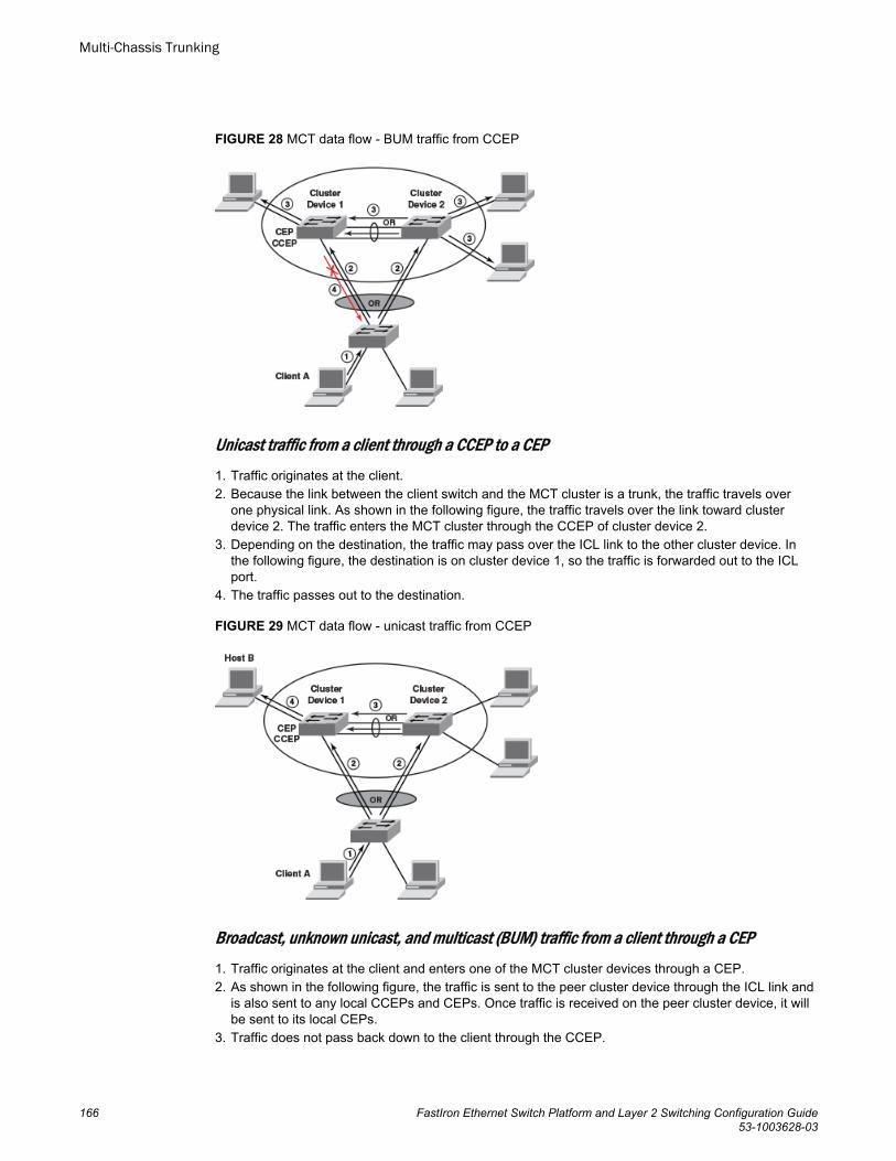
FIGURE 28 MCT data flow - BUM traffic from CCEP
Unicast traffic from a client through a CCEP to a CEP1. Traffic originates at the client.2. Because the link between the client switch and the MCT cluster is a trunk, the traffic travels over
one physical link. As shown in the following figure, the traffic travels over the link toward clusterdevice 2. The traffic enters the MCT cluster through the CCEP of cluster device 2.
3. Depending on the destination, the traffic may pass over the ICL link to the other cluster device. Inthe following figure, the destination is on cluster device 1, so the traffic is forwarded out to the ICLport.
4. The traffic passes out to the destination.
FIGURE 29 MCT data flow - unicast traffic from CCEP
Broadcast, unknown unicast, and multicast (BUM) traffic from a client through a CEP1. Traffic originates at the client and enters one of the MCT cluster devices through a CEP.2. As shown in the following figure, the traffic is sent to the peer cluster device through the ICL link and
is also sent to any local CCEPs and CEPs. Once traffic is received on the peer cluster device, it willbe sent to its local CEPs.
3. Traffic does not pass back down to the client through the CCEP.
Multi-Chassis Trunking
166 FastIron Ethernet Switch Platform and Layer 2 Switching Configuration Guide53-1003628-03
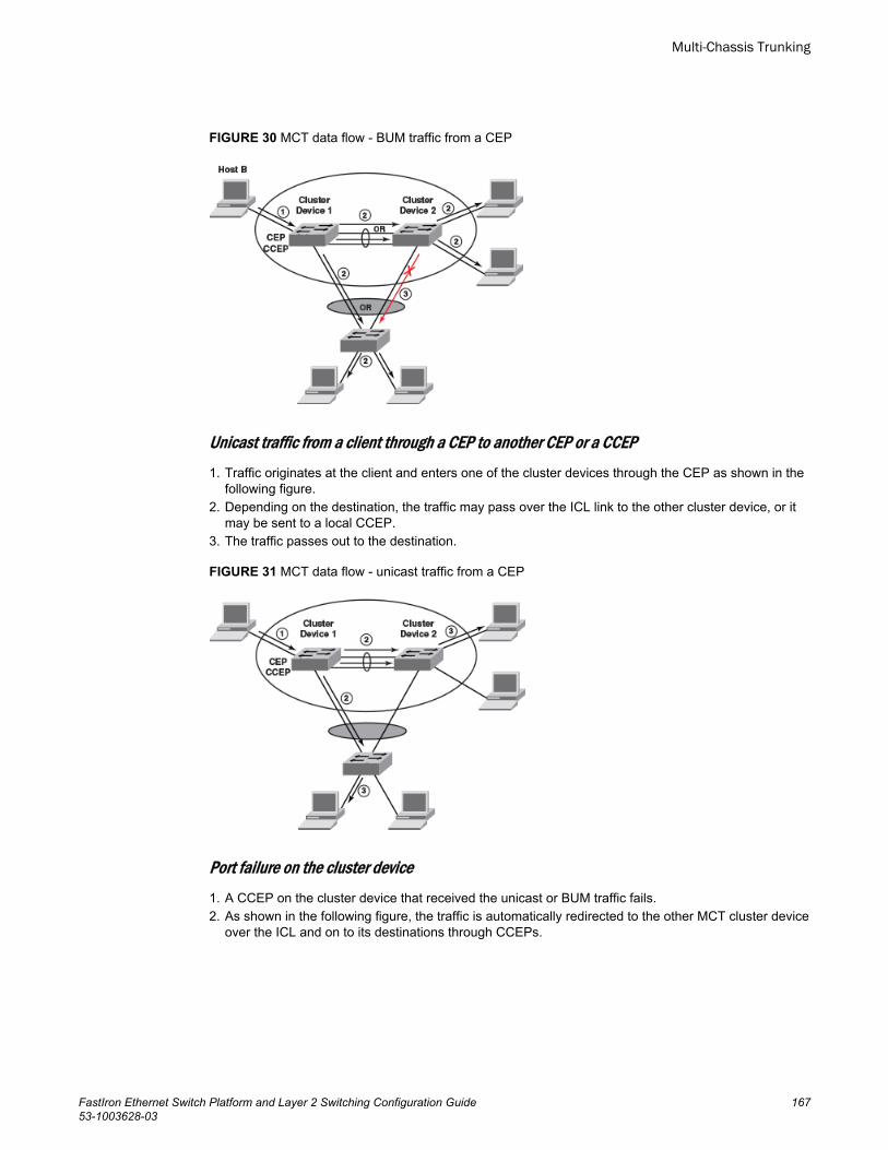
FIGURE 30 MCT data flow - BUM traffic from a CEP
Unicast traffic from a client through a CEP to another CEP or a CCEP1. Traffic originates at the client and enters one of the cluster devices through the CEP as shown in the
following figure.2. Depending on the destination, the traffic may pass over the ICL link to the other cluster device, or it
may be sent to a local CCEP.3. The traffic passes out to the destination.
FIGURE 31 MCT data flow - unicast traffic from a CEP
Port failure on the cluster device1. A CCEP on the cluster device that received the unicast or BUM traffic fails.2. As shown in the following figure, the traffic is automatically redirected to the other MCT cluster device
over the ICL and on to its destinations through CCEPs.
Multi-Chassis Trunking
FastIron Ethernet Switch Platform and Layer 2 Switching Configuration Guide 16753-1003628-03
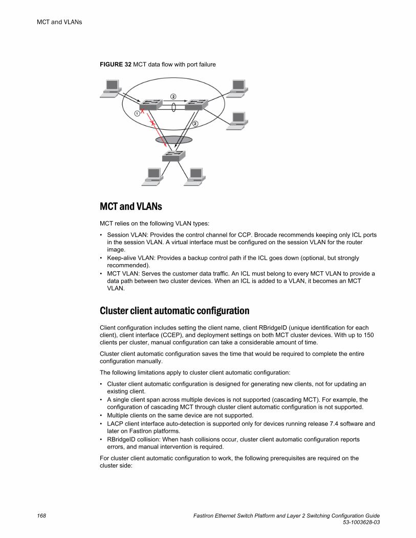
FIGURE 32 MCT data flow with port failure
MCT and VLANsMCT relies on the following VLAN types:
• Session VLAN: Provides the control channel for CCP. Brocade recommends keeping only ICL portsin the session VLAN. A virtual interface must be configured on the session VLAN for the routerimage.
• Keep-alive VLAN: Provides a backup control path if the ICL goes down (optional, but stronglyrecommended).
• MCT VLAN: Serves the customer data traffic. An ICL must belong to every MCT VLAN to provide adata path between two cluster devices. When an ICL is added to a VLAN, it becomes an MCTVLAN.
Cluster client automatic configurationClient configuration includes setting the client name, client RBridgeID (unique identification for eachclient), client interface (CCEP), and deployment settings on both MCT cluster devices. With up to 150clients per cluster, manual configuration can take a considerable amount of time.
Cluster client automatic configuration saves the time that would be required to complete the entireconfiguration manually.
The following limitations apply to cluster client automatic configuration:
• Cluster client automatic configuration is designed for generating new clients, not for updating anexisting client.
• A single client span across multiple devices is not supported (cascading MCT). For example, theconfiguration of cascading MCT through cluster client automatic configuration is not supported.
• Multiple clients on the same device are not supported.• LACP client interface auto-detection is supported only for devices running release 7.4 software and
later on FastIron platforms.• RBridgeID collision: When hash collisions occur, cluster client automatic configuration reports
errors, and manual intervention is required.
For cluster client automatic configuration to work, the following prerequisites are required on thecluster side:
MCT and VLANs
168 FastIron Ethernet Switch Platform and Layer 2 Switching Configuration Guide53-1003628-03
• The cluster must be configured on both MCT cluster devices.• An MCT VLAN must be configured on both MCT cluster devices.• The trunk group configuration must be removed from the client interfaces.• The client interfaces must be up and operational.• The cluster ID must be unique when there are multiple clusters interconnected in a topology. For
example, in a cascaded Stage 2 MCT cluster, the cluster ID on a stage 1 pair of switch should bedifferent from the cluster ID on a stage 2 pair of switches.
The following prerequisites are required on the client side:
• VLAN and trunk group configuration must be completed.• Link Level Discovery Protocol (LLDP) must be enabled.
Refer to Setting up cluster client automatic configuration on page 174 for detailed instructions on thecluster client automatic configuration process.
MCT feature interactionThe following FastIron features are supported with MCT. All security features are locally significant andare not synchronized across an MCT cluster.
• LACP on the CCEP.• VRRP on the CCEP.• MRP and MRP II, with the restriction that the ICL port cannot be the secondary port of the MRP ring.• Flooding features (such as VLAN CPU protection and multicast flooding) on MCT VLANs.• Unidirectional Link Detection (UDLD) as independent boxes (configured independently).• ARP as independent boxes (configured independently).• STP and RSTP.• Ingress ACLs on all MCT ports. Egress ACLs are supported only on MCT CEPs or ICL ports. Egress
ACLs are not supported on MCT CCEPs.• QoS and MAC filters and profiles with the same configuration on both cluster devices.• IPv4 ACLs and rate limits. If the rules are applied on the CCEPs, the same rules must be applied to
the CCEP ports on both cluster devices.• Layer 3 Routing. VE with IP address assignment is supported on CCEPs for VRRP.• Static multi-port MAC.• Port MAC security, multi-port authentication, and 802.1X, only on CEPs.• Static MAC address configuration. Static MAC addresses are programmed on both local and remote
peers as static entries.• DAI and DHCP snooping for clients connected through CEPs. They must be configured
independently on both cluster devices.
‐ If the trusted ports are off the CCEP, the arp inspection trust or dhcp snoop trust commandmust be used on the CCEPs and ICL ports.
‐ DHCP and ARP entries are created on both MCT cluster devices if the flow traverses both theCCEP and ICL.
• Hitless failover. If the failover operation is performed with a cluster configuration, the TCP session isreestablished. The MAC addresses from the cluster peer devices are revalidated and programmedaccordingly.
• Hitless upgrade. If the upgrade operation is performed with a cluster configuration, the TCP sessionis reestablished. The MAC addresses from the cluster peer devices are revalidated and programmedaccordingly.
The following FastIron features are not supported with MCT:
• LACP on ICL.• MSTP, VSRP, RIP.
MCT feature interaction
FastIron Ethernet Switch Platform and Layer 2 Switching Configuration Guide 16953-1003628-03
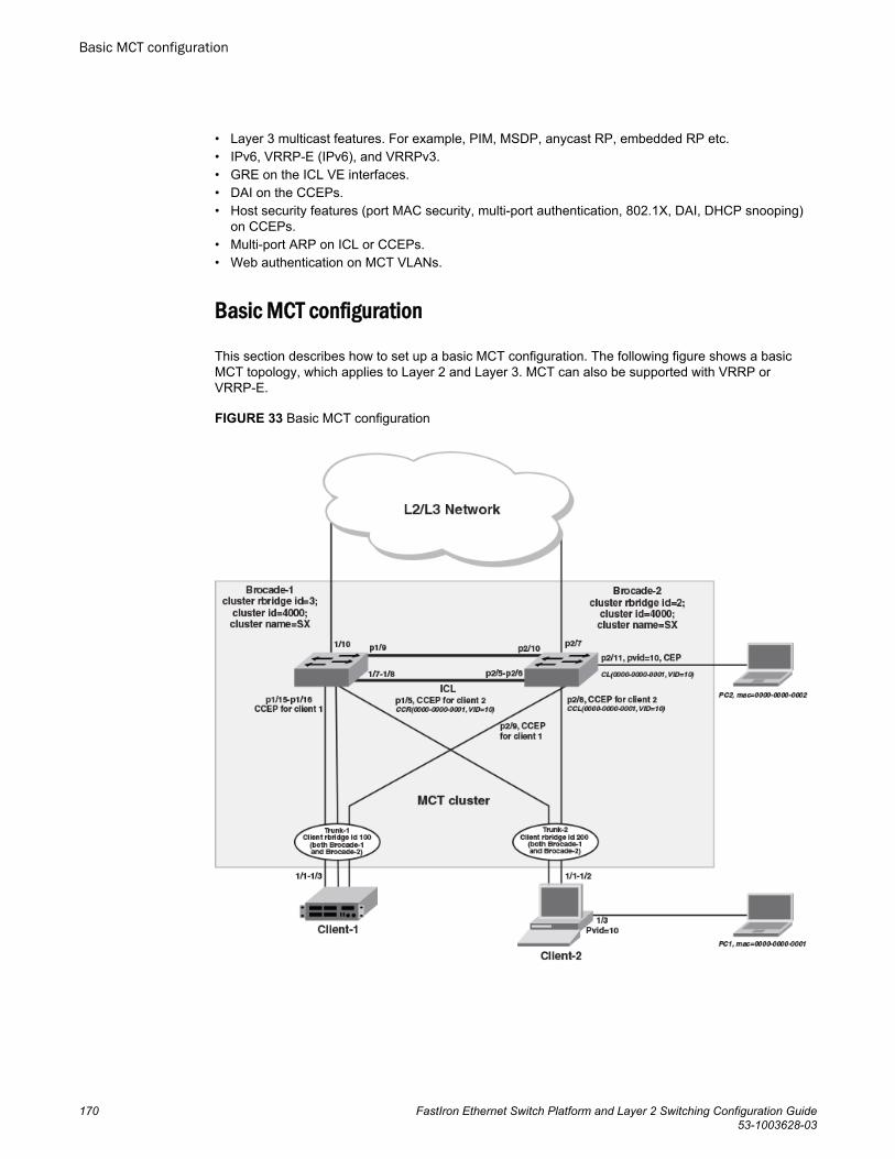
• Layer 3 multicast features. For example, PIM, MSDP, anycast RP, embedded RP etc.• IPv6, VRRP-E (IPv6), and VRRPv3.• GRE on the ICL VE interfaces.• DAI on the CCEPs.• Host security features (port MAC security, multi-port authentication, 802.1X, DAI, DHCP snooping)
on CCEPs.• Multi-port ARP on ICL or CCEPs.• Web authentication on MCT VLANs.
Basic MCT configuration
This section describes how to set up a basic MCT configuration. The following figure shows a basicMCT topology, which applies to Layer 2 and Layer 3. MCT can also be supported with VRRP orVRRP-E.
FIGURE 33 Basic MCT configuration
Basic MCT configuration
170 FastIron Ethernet Switch Platform and Layer 2 Switching Configuration Guide53-1003628-03
MCT configuration considerations
• Configuring flow-based MAC address learning and MCT on the same device is not supported.• When running STP, the STP state should be the same on both cluster devices. For additional
information on running STP with MCT, refer to "STP/RSTP" under MCT Layer 2 protocols and torelated configuration examples.
• One ICL can be configured per device, and a device can be in only one cluster.• The software version in both cluster devices must be exactly the same for the cluster to function.• An ICL port should not be an untagged member of any VLAN.• It is recommended that you set up ICL as a static LAG with at least two ports. This provides port-level
redundancy and higher bandwidth for cluster communication.• ICL ports must be part of MCT VLANs and session VLANs.• An ICL cannot be a regular port link or an LACP trunk. It must be a single or multiple ports static
LAG.• MAC learning is disabled on ICL ports for all VLANs.• MDUP synchronizes all MAC entries for VLANs served by an ICL link.• In any MCT configuration, there are two different cluster-related IDs, the Cluster ID and the Cluster
RBridge ID. The Cluster ID uniquely identifies a cluster. All cluster devices in the same MCT clusterhave the same Cluster ID. The Cluster RBridge ID uniquely identifies a cluster device within thecluster. To avoid conflicts, ensure that the Cluster ID and the Cluster RBridge ID are unique within anMCT configuration and cannot be confused with each other.
• The cluster ID should be the same on both cluster devices.• The cluster RBridgeID should not conflict with any client RBridgeID or with the peer RBridgeID.• The client RBridgeID is unique and should be the same on cluster devices.• Brocade recommends keeping only ICL ports in the session VLAN during operation.• MCT can support up to 16 members per trunk group, depending on the software version and Switch
type.• An ICL interface cannot be configured as the CCEP in any client.• BPDU guard and root guard configuration should be identical on both cluster devices.• Because Egress PCL is configured on CCEPs, egress ACL cannot be configured on them. All types
of ingress ACLs, DoS attack prevention, and so on can still be configured on those ports.• Brocade recommends that you configure a keep-alive VLAN as a separate link (not ICL). The keep-
alive VLAN provides a backup control path when CCP goes down.• 48GC ports should not be used as MCT trunks or CCEP ports.
Differences in configuring MCT for the switch and router image
There are some differences in the MCT configuration for the switch image versus the router image:
• On a switch image, STP is by default enabled for all the VLANs; however, for MCT, Layer 2 protocolssuch as STP and RSTP should not be enabled on the session VLAN. Therefore, STP must bedisabled explicitly for the session VLAN. STP is automatically disabled in the router image.
• Virtual Ethernet (VE) cannot be configured on a session VLAN in a switch image, but an IP addressis needed for the cluster devices to communicate via CCP. Therefore, in a switch image, theconfigured management IP address is used to establish communication between the cluster devices.
• The management IP addresses in each of the cluster devices should be configured in the samesubnet. If the IP addresses are in different subnets, ARP does not resolve the addresses, and MCTmay not work. ARP for the peer cluster devices is always learned on the ICL port or trunk, so anymanagement traffic between the two devices always goes through the ICL ports.
NOTECLI may vary somewhat among different Brocade platforms. These variations are not documented inthe configuration examples provided in this chapter.
MCT configuration considerations
FastIron Ethernet Switch Platform and Layer 2 Switching Configuration Guide 17153-1003628-03
Configuring MCT
This section provides basic configuration steps, which should be completed in the specified order.
Step 1: Configure ICL and LAGs for client devices on page 172
Step 2: Configure the MCT VLAN, MCT session VLAN, and recommended MCT keep-alive VLAN onpage 172
Step 3: Configure the cluster on page 173
Step 4: Configure clients on page 174
After completing these steps, you can verify the configuration by running the show cluster command.Refer to Displaying peer and client states on page 188.
Step 1: Configure ICL and LAGs for client devices
You can configure a static or dynamic LAG. Static LAG groups are manually configured aggregatelinks containing multiple ports. Dynamic LAGs use Link Aggregation Control Protocol (LACP) tomaintain aggregate links over multiple port. LACP PDUs are exchanged between ports on each deviceto determine if the connection is still active. The LAG then shuts down any port whose connection isno longer active. You can configure static or dynamic LAGs for cluster clients. Static LAGs aremanually configured aggregate links containing multiple ports. Dynamic LAGs use Link AggregationControl Protocol (LACP) to maintain aggregate links over multiple ports. LACP PDUs are exchangedbetween ports on each device to determine if the connection is still active. The LAG then shuts downany port whose connection is no longer active.
NOTEICL LAGs support only static trunks.
Syntax: [no] lag lag-name [ { static | dynamic } [ id number ] ]
To configure an ICL static LAG, enter the following commands.
device-1(config)# lag MCT_lag1 static id 2Brocade-1(config-lag-MCT_lag1)# ports ethernet 1/1/7 to 1/1/8Brocade-1(config-lag-MCT_lag1)# primary-port 1/1/7Brocade-1(config-lag-MCT_lag1)# deployTo configure a dynamic LAG for a client device, enter the following commands for each MCT clusterdevice.
device-1(config)# lag client_lag2 dynamic id 5Brocade-1(config-lag-client_lag2)# ports ethernet 1/2/11Brocade-1(config-lag-client_lag2)# primary-port 1/2/11Brocade-1(config-lag-client_lag2)# deploy
Step 2: Configure the MCT VLAN, MCT session VLAN, and recommended MCT keep-alive VLAN
To create the MCT session VLAN and recommended MCT keep-alive VLAN for Brocade-1 in thetopology of Figure 33 on page 170, enter the following commands.
device-1(config)# vlan 3001 name MCT-keep-alive device-1(config-vlan-3001)# tagged ethernet 1/1/9device-1(config-vlan-3001)# exitdevice-1(config)# vlan 3000 name Session-VLANdevice-1(config-vlan-3000)# tagged ether 1/1/7 to 1/1/8device-1(config-vlan-3000)# no spanning-tree
Configuring MCT
172 FastIron Ethernet Switch Platform and Layer 2 Switching Configuration Guide53-1003628-03
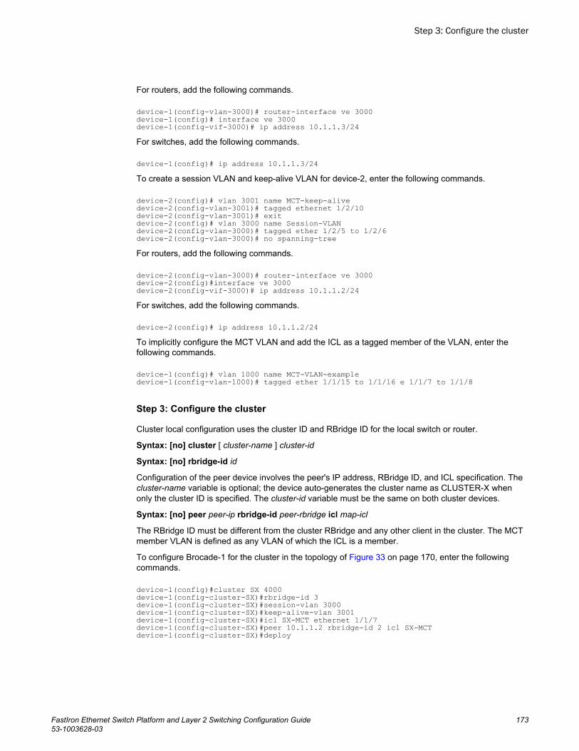
For routers, add the following commands.
device-1(config-vlan-3000)# router-interface ve 3000device-1(config)# interface ve 3000device-1(config-vif-3000)# ip address 10.1.1.3/24For switches, add the following commands.
device-1(config)# ip address 10.1.1.3/24To create a session VLAN and keep-alive VLAN for device-2, enter the following commands.
device-2(config)# vlan 3001 name MCT-keep-alive device-2(config-vlan-3001)# tagged ethernet 1/2/10device-2(config-vlan-3001)# exitdevice-2(config)# vlan 3000 name Session-VLANdevice-2(config-vlan-3000)# tagged ether 1/2/5 to 1/2/6device-2(config-vlan-3000)# no spanning-treeFor routers, add the following commands.
device-2(config-vlan-3000)# router-interface ve 3000device-2(config)#interface ve 3000device-2(config-vif-3000)# ip address 10.1.1.2/24For switches, add the following commands.
device-2(config)# ip address 10.1.1.2/24To implicitly configure the MCT VLAN and add the ICL as a tagged member of the VLAN, enter thefollowing commands.
device-1(config)# vlan 1000 name MCT-VLAN-exampledevice-1(config-vlan-1000)# tagged ether 1/1/15 to 1/1/16 e 1/1/7 to 1/1/8
Step 3: Configure the cluster
Cluster local configuration uses the cluster ID and RBridge ID for the local switch or router.
Syntax: [no] cluster [ cluster-name ] cluster-id
Syntax: [no] rbridge-id id
Configuration of the peer device involves the peer's IP address, RBridge ID, and ICL specification. Thecluster-name variable is optional; the device auto-generates the cluster name as CLUSTER-X whenonly the cluster ID is specified. The cluster-id variable must be the same on both cluster devices.
Syntax: [no] peer peer-ip rbridge-id peer-rbridge icl map-icl
The RBridge ID must be different from the cluster RBridge and any other client in the cluster. The MCTmember VLAN is defined as any VLAN of which the ICL is a member.
To configure Brocade-1 for the cluster in the topology of Figure 33 on page 170, enter the followingcommands.
device-1(config)#cluster SX 4000 device-1(config-cluster-SX)#rbridge-id 3 device-1(config-cluster-SX)#session-vlan 3000device-1(config-cluster-SX)#keep-alive-vlan 3001device-1(config-cluster-SX)#icl SX-MCT ethernet 1/1/7 device-1(config-cluster-SX)#peer 10.1.1.2 rbridge-id 2 icl SX-MCT device-1(config-cluster-SX)#deploy
Step 3: Configure the cluster
FastIron Ethernet Switch Platform and Layer 2 Switching Configuration Guide 17353-1003628-03
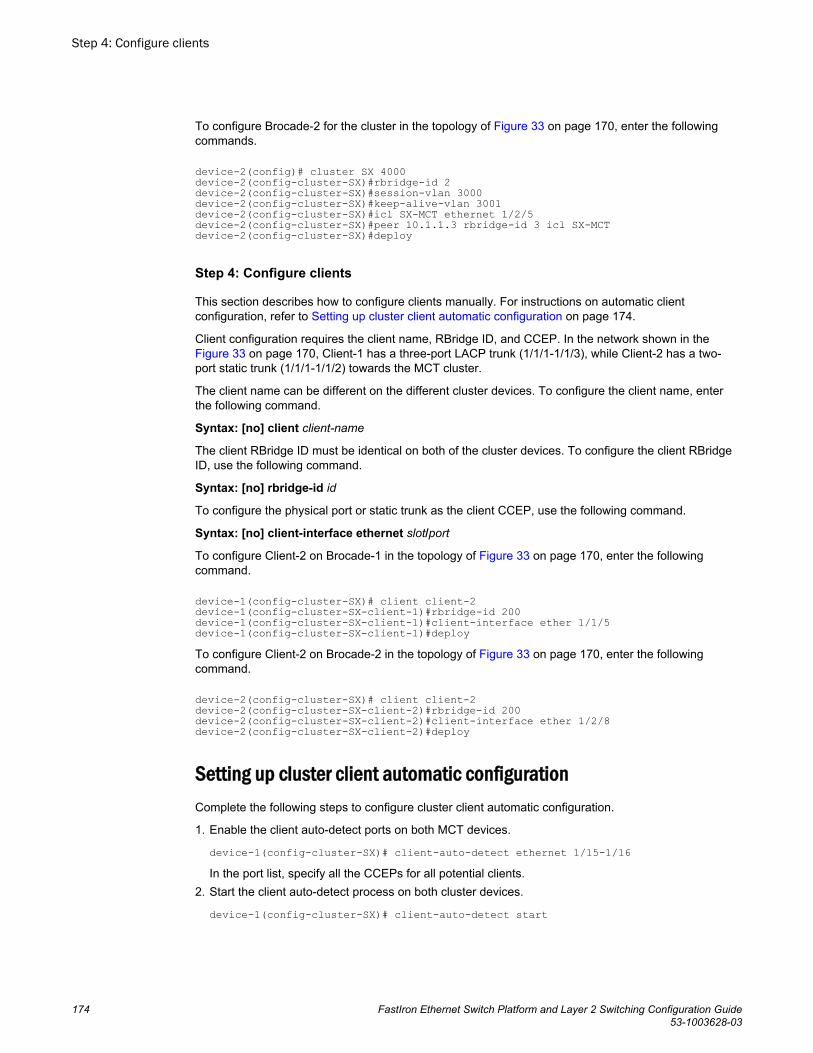
To configure Brocade-2 for the cluster in the topology of Figure 33 on page 170, enter the followingcommands.
device-2(config)# cluster SX 4000 device-2(config-cluster-SX)#rbridge-id 2 device-2(config-cluster-SX)#session-vlan 3000device-2(config-cluster-SX)#keep-alive-vlan 3001device-2(config-cluster-SX)#icl SX-MCT ethernet 1/2/5 device-2(config-cluster-SX)#peer 10.1.1.3 rbridge-id 3 icl SX-MCT device-2(config-cluster-SX)#deploy
Step 4: Configure clients
This section describes how to configure clients manually. For instructions on automatic clientconfiguration, refer to Setting up cluster client automatic configuration on page 174.
Client configuration requires the client name, RBridge ID, and CCEP. In the network shown in the Figure 33 on page 170, Client-1 has a three-port LACP trunk (1/1/1-1/1/3), while Client-2 has a two-port static trunk (1/1/1-1/1/2) towards the MCT cluster.
The client name can be different on the different cluster devices. To configure the client name, enterthe following command.
Syntax: [no] client client-name
The client RBridge ID must be identical on both of the cluster devices. To configure the client RBridgeID, use the following command.
Syntax: [no] rbridge-id id
To configure the physical port or static trunk as the client CCEP, use the following command.
Syntax: [no] client-interface ethernet slot/port
To configure Client-2 on Brocade-1 in the topology of Figure 33 on page 170, enter the followingcommand.
device-1(config-cluster-SX)# client client-2device-1(config-cluster-SX-client-1)#rbridge-id 200device-1(config-cluster-SX-client-1)#client-interface ether 1/1/5device-1(config-cluster-SX-client-1)#deployTo configure Client-2 on Brocade-2 in the topology of Figure 33 on page 170, enter the followingcommand.
device-2(config-cluster-SX)# client client-2device-2(config-cluster-SX-client-2)#rbridge-id 200device-2(config-cluster-SX-client-2)#client-interface ether 1/2/8device-2(config-cluster-SX-client-2)#deploy
Setting up cluster client automatic configurationComplete the following steps to configure cluster client automatic configuration.
1. Enable the client auto-detect ports on both MCT devices.
device-1(config-cluster-SX)# client-auto-detect ethernet 1/15-1/16In the port list, specify all the CCEPs for all potential clients.
2. Start the client auto-detect process on both cluster devices.
device-1(config-cluster-SX)# client-auto-detect start
Step 4: Configure clients
174 FastIron Ethernet Switch Platform and Layer 2 Switching Configuration Guide53-1003628-03
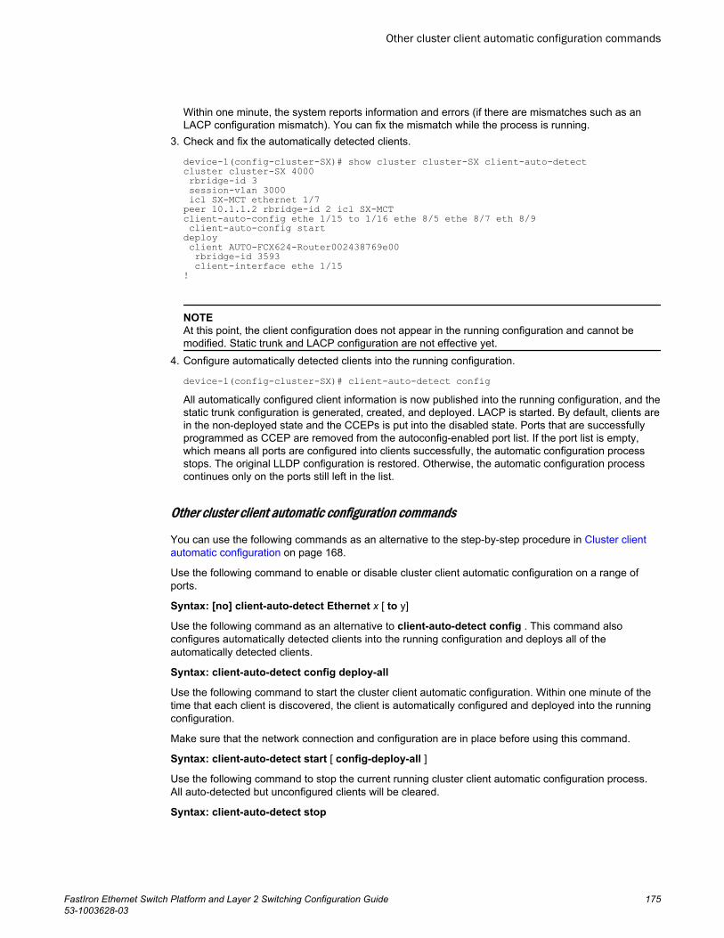
Within one minute, the system reports information and errors (if there are mismatches such as anLACP configuration mismatch). You can fix the mismatch while the process is running.
3. Check and fix the automatically detected clients.
device-1(config-cluster-SX)# show cluster cluster-SX client-auto-detect cluster cluster-SX 4000 rbridge-id 3 session-vlan 3000 icl SX-MCT ethernet 1/7peer 10.1.1.2 rbridge-id 2 icl SX-MCTclient-auto-config ethe 1/15 to 1/16 ethe 8/5 ethe 8/7 eth 8/9 client-auto-config startdeploy client AUTO-FCX624-Router002438769e00 rbridge-id 3593 client-interface ethe 1/15 !
NOTEAt this point, the client configuration does not appear in the running configuration and cannot bemodified. Static trunk and LACP configuration are not effective yet.
4. Configure automatically detected clients into the running configuration.
device-1(config-cluster-SX)# client-auto-detect configAll automatically configured client information is now published into the running configuration, and thestatic trunk configuration is generated, created, and deployed. LACP is started. By default, clients arein the non-deployed state and the CCEPs is put into the disabled state. Ports that are successfullyprogrammed as CCEP are removed from the autoconfig-enabled port list. If the port list is empty,which means all ports are configured into clients successfully, the automatic configuration processstops. The original LLDP configuration is restored. Otherwise, the automatic configuration processcontinues only on the ports still left in the list.
Other cluster client automatic configuration commands
You can use the following commands as an alternative to the step-by-step procedure in Cluster clientautomatic configuration on page 168.
Use the following command to enable or disable cluster client automatic configuration on a range ofports.
Syntax: [no] client-auto-detect Ethernet x [ to y]
Use the following command as an alternative to client-auto-detect config . This command alsoconfigures automatically detected clients into the running configuration and deploys all of theautomatically detected clients.
Syntax: client-auto-detect config deploy-all
Use the following command to start the cluster client automatic configuration. Within one minute of thetime that each client is discovered, the client is automatically configured and deployed into the runningconfiguration.
Make sure that the network connection and configuration are in place before using this command.
Syntax: client-auto-detect start [ config-deploy-all ]
Use the following command to stop the current running cluster client automatic configuration process.All auto-detected but unconfigured clients will be cleared.
Syntax: client-auto-detect stop
Other cluster client automatic configuration commands
FastIron Ethernet Switch Platform and Layer 2 Switching Configuration Guide 17553-1003628-03
MCT failover scenariosThe following scenarios describe what happens if specific elements in the MCT configuration fail.
• Client interface on one of the MCT cluster devices goes down.
‐ Traffic switches to the other cluster device with minimal traffic loss.
• MCT cluster device goes down.
‐ When an MCT cluster device goes down (for example, due to a power failure), the traffic failsover to the other MCT cluster device.
• Hitless failover occurs.
‐ The MCT CCEPs stay up during hitless switchover, failover, or upgrade. Link protocols such asUDLD and LACP on CCEPs do not flap. Traffic disruption is minimal (sub-second). The MCTCCP connection flaps once, and MAC is re-synced between the peer devices.
‐ The CCP goes down and comes back up again once the hitless failover is completed.
• ICL interface or CCP goes down (keep-alive is configured).
‐ If a keep-alive VLAN is used, the devices in the cluster can communicate even if the ICL goesdown. If the peer device is reachable over the keep-alive VLAN, the MCT peers perform themaster/slave negotiation per client. After negotiation, the slave shuts down its client ports, andthe master client ports continue to forward the traffic.
‐ The master/slave negotiation is performed per MCT client on the basis of RBridgeID and clientLocal or Remote accessibility. If the client is reachable from both MCT devices, the lowerRBridgeID becomes the master. If the client can be accessed only from one of the MCT devices,the cluster device on which it is reachable becomes the master.
‐ If the peer device cannot be reached over the keep-alive VLAN, then both cluster devices keepforwarding.
NOTEBrocade recommends using keep-alive VLANs with the MCT configurations. This provides alternativeaccess if the ICL interface goes down. However, a keep-alive VLAN should not be configured whenbpdu-flood-enable is configured. Refer to BPDU forwarding on page 183.
• ICL interface or CCP goes down (keep-alive is not configured).
‐ When the keep-alive VLAN is not configured, both cluster devices keep forwarding. Use theclient-isolation strict command to disable the client interface as soon as the ICL link goes downto completely isolate the client.
• Double failures occur (for example, the ICL goes down and the client interface goes down on one ofthe MCT cluster devices).
‐ Multiple failures could cause traffic to drop, even if there is a physical path available.
NOTEThe keep-alive link is supported on the ICX 7750 in an SSTP or MST environment, even though ICX7750 has the BPDU flood-enable feature built in. This is because the BPDU flood-enable in the ICX7750 is hardware enabled.
MCT failover scenarios
176 FastIron Ethernet Switch Platform and Layer 2 Switching Configuration Guide53-1003628-03
NOTEWith the ICX 6650 and SX chassis, if the environment uses SSTP or MST in an MCT configuration,then the keep-alive link is not supported with the BPDU flood enable command. This is because thecommand is software-based in the ICX 6650 and SX chassis.
Cluster failover mode
The following failover modes can be configured with MCT:
• Fast-failover (default) - As soon as the ICL interface goes down, the CCP goes down. All the remoteMAC addresses are flushed.
• Slow-failover - Even if the ICL interface goes down, the CCP waits for the hold-time before taking theCCP down. Remote MAC addresses are flushed only when the CCP is down.
To disable the fast-failover mode, enter a command such as the following.
device-1(config-cluster-SX)# peer 10.1.1.3 disable-fast-failoverSyntax: [no] peer peer-ip disable-fast-failover
Client isolation mode
NOTEYou must create the same isolation mode on both cluster devices. The CLI will allow modification of theclient isolation mode on MCT cluster devices even when the cluster is deployed.
MCT cluster devices can operate in two modes. Both peer devices should be configured in the samemode.
Loose mode (default): When the CCP goes down, the peer device performs the master/slavenegotiation. After negotiation, the slave shuts down its peer ports, but the master peer ports continue toforward traffic if a keep-alive VLAN is configured.
If a keep-alive VLAN is not configured, both peer devices become masters, and both of the client portsstay up.
device-1(config-cluster-SX)# client-isolation looseStrict mode: When the CCP goes down, the interfaces on both the cluster devices are administrativelyshut down. In this mode, the client is completely isolated from the network if the CCP is not operational.
device-1(config-cluster-SX)# client-isolation strictSyntax: [no] client-isolation strict
Shutting down all client interfaces
Use the client-interfaces shutdown command when performing a hitless upgrade operation. Thiscommand can be used to shut down all the local client interfaces in the cluster, which results in failoverof traffic to the peer device.
device-1(config-cluster-SX)# client-interfaces shutdownSyntax: [no] client-interfaces shutdown
Cluster failover mode
FastIron Ethernet Switch Platform and Layer 2 Switching Configuration Guide 17753-1003628-03
Using the keep-alive VLAN
CCRR messages are used to exchange information between peer devices. When the CCP is up,CCRR messages are sent over the CCP. When the CCP client cannot be reached or the ICL is down,you can use the keep-alive-vlan command under the cluster context so CCRR messages areperiodically sent over the keep-alive VLAN. Only one VLAN can be configured as a keep-alive VLAN.The keep-alive VLAN cannot be a member VLAN of the MCT, and this VLAN can be tagged oruntagged.
NOTEKeep-alive VLAN configuration is not allowed when the client isolation mode is strict. When a keep-alive VLAN is configured, client isolation mode cannot be configured as strict.
device-1(config-cluster-SX))# keep-alive-vlan 10Syntax: [no] keep-alive-vlan vlan-id
The vlan_id variable specifies the VLAN range. Possible values are from 1 to 4089.
When the CCP is down, the following results occur.
• If the keep-alive VLAN is configured, CCRR messages are sent every second over that VLAN.• When CCP is down and a keep-alive VLAN is configured, master/slave selection is based on the
following criteria:
‐ If one device’s CCEPs are up and the peer’s CCEPs are down, the peer with the local CCEPsdown becomes the slave.
‐ Otherwise, the device with the higher RBridgeID becomes the slave.• If no packets are received from the peer device for a period of three seconds, the peer is
considered down.• If a keep-alive VLAN is not configured and both the peer devices are up, both peers keep
forwarding traffic independently.
Setting keep-alive timers and hold-time
To specify the keep-alive timers and hold time for the peer devices, enter a command such as thefollowing.
device-1(config-cluster-SX))# peer 10.1.1.3 timers keep-alive 40 hold-time 120Syntax: [no] peer peer-ip timers keep-alive keep-alive-time hold-time hold-time
The peer-ip parameter should be in the same subnet as the cluster management interface.
The keep-alive-time variable can be from 0 to 21845 seconds. The default is 10 seconds.
The hold-time variable can be from 3 to 65535 seconds and must be at least 3 times the keep-alivetime. The default is 90 seconds.
NOTEThe keep-alive VLAN and keep-alive timers are not related. The keep-alive timer is used by CCP.
Using the keep-alive VLAN
178 FastIron Ethernet Switch Platform and Layer 2 Switching Configuration Guide53-1003628-03
Layer 2 behavior with MCTThis section describes the Layer 2 behavior when MCT is configured.
MAC operationsThis section describes configuration operations related to MAC addresses.
MAC Database Update
Each MAC address is advertised with a cost. Low-cost MAC addresses are given preference over high-cost addresses. MAC addresses that are learned locally are given the highest priority, or the cost of 0,so that they are always selected as the best MAC address.
If a MAC address moves from a CCEP port to a CEP port, a MAC move message is sent to the peer,and the peer moves the MAC address from its CCEP ports to the ICL links.
If two MAC addresses have the same cost, the address learned from the lower RBridgeID wins and isinstalled in the FDB.
MAC addresses in MCT VLANs are updated across the cluster using MDUP messages.
Cluster MAC types
Cluster Local MAC (CL): MAC addresses that are learned on the MCT VLAN and on CEPs locally.MAC addresses are synchronized to the cluster peer device and are subject to aging.
Cluster Remote MAC (CR): MAC addresses that are learned via MDUP messages from the peerdevice (CL on the peer). The MAC addresses are always programmed on the ICL port and do not age.The CR is deleted only when the CL is deleted from the peer. An MDB entry is created for these MACaddresses with a cost of 1 and is associated with the peer RBridgeID.
Cluster Client Local MAC (CCL): MAC addresses that are learned on the MCT VLAN and on CCEPs.
The MAC addresses are synchronized to the cluster peer device and are subject to aging. An MDBentry with a cost of 0 is created for these addresses, and they are associated with the client and clusterRBridgeIDs.
Cluster Client Remote MAC (CCR): MAC addresses that are learned via MDUP message from thepeer device (CCL on the peer). The MAC addresses are always programmed on the correspondingCCEP port and do not age. The CCR is deleted only when the CCL is deleted from the peer. An MDBentry with the cost of 1 is created for the MAC addresses, and they are associated with the client andpeer RBridgeIDs.
Cluster Multi-Destination Local MAC (CML): A static MAC entry that is configured locally on the MCTVLAN. Any static MAC address configured on MCT VLAN will have the ICL added by default.Consequently, the address automatically becomes a multi-destination MAC entry. The localconfiguration generates a local MDB. Any CML entry can still have up to 2 associated MDBs, one localand one remote. The remote MDB contains the remote static configuration for the same MAC andVLAN. If the dynamic MAC and static configuration co-exist, the dynamic MAC address is removed,whether it is learned locally or from MDUP. The port list of a CML entry contains an ICL port, the clientports from the client list in the local configuration and the remote configuration (if it exists), and all locallyconfigured CEP ports.
Cluster Multi-Destination Remote MAC (CMR): A static MAC entry that is configured on the MCTVLAN on the peer side and has no associated local configuration. The CMR entry has only theinformation from the remote MDB. The port list of a CMR entry contains an ICL port and all the client
Layer 2 behavior with MCT
FastIron Ethernet Switch Platform and Layer 2 Switching Configuration Guide 17953-1003628-03
ports from the client list in the remote configuration. When there is a local configuration for the sameentry, the CMR is converted to the CML.
MAC aging
Only the local MAC entries are aged on a cluster device. The remote MAC address entries are agedbased on explicit MDUP messages only.
The remote MAC addresses learned through MDUP messages are dynamic addresses, but they neverage from the FDB.
MAC flush
If the CEP is down, the MAC addresses are flushed, and individual MAC deletion messages are sentto the peer device.
If the CCEP local port is down, the MAC addresses are flushed locally, and individual MAC deletionmessages are sent to the peer device.
If the clear mac command is given, all the MDB and FDB are rebuilt.
If the clear mac vlan command is given, all the local MDB and FDB are rebuilt for the VLAN.
MAC movement happens normally on the local device.
CEP to CCEP MAC movement - MAC movement happens normally on the local device, and it deletesall the other MDBs from the peer to create a new local MDB.
MAC show commands
To display all local MAC address entries for a cluster, use the show mac cluster command.
device# show mac-address cluster 1000Total Cluster Enabled(CL+CR+CCL+CCR) MACs: 1Total Cluster Local(CL) MACs: 1CCL: Cluster Client Local CCR:Cluster Client Remote CL:Local CR:RemoteTotal active entries from all ports = 1Total static entries from all ports = 3MAC-Address Port Type Index MCT-Type VLAN 0000.0022.3333 1/8/1 Static 4254 CML 20 0000.0022.3333 1/8/3 Static 4254 CML 20 0000.0022.3333 1/8/13 Static 4254 CML 20 Syntax: show mac-address [ cluster { id|name } local| remote]
MAC clear commands
To clear all MAC addresses in the system, enter the following command.
device# clear macSyntax: clear mac
NOTEOn SXL with authentication protocols and high traffic, the clear mac and mac flush operations log a lotof new address messages, which results in high CPU utilization for a few minutes.
MAC show commands
180 FastIron Ethernet Switch Platform and Layer 2 Switching Configuration Guide53-1003628-03
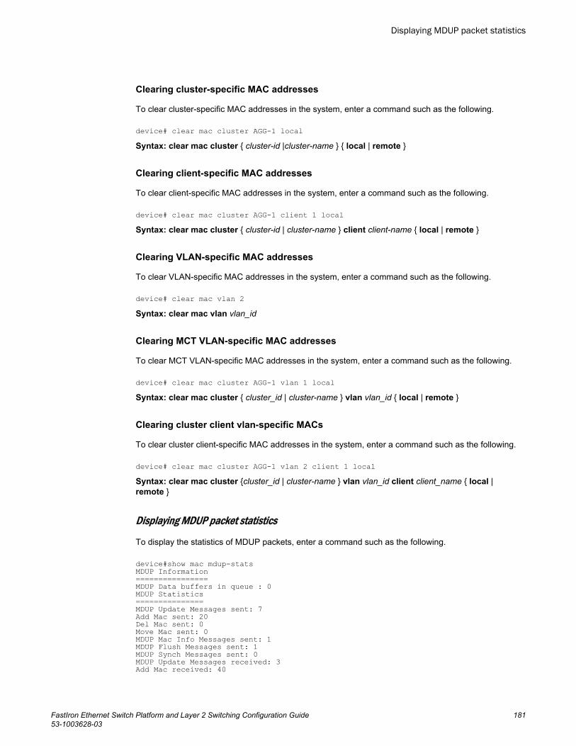
Clearing cluster-specific MAC addresses
To clear cluster-specific MAC addresses in the system, enter a command such as the following.
device# clear mac cluster AGG-1 localSyntax: clear mac cluster { cluster-id |cluster-name } { local | remote }
Clearing client-specific MAC addresses
To clear client-specific MAC addresses in the system, enter a command such as the following.
device# clear mac cluster AGG-1 client 1 localSyntax: clear mac cluster { cluster-id | cluster-name } client client-name { local | remote }
Clearing VLAN-specific MAC addresses
To clear VLAN-specific MAC addresses in the system, enter a command such as the following.
device# clear mac vlan 2Syntax: clear mac vlan vlan_id
Clearing MCT VLAN-specific MAC addresses
To clear MCT VLAN-specific MAC addresses in the system, enter a command such as the following.
device# clear mac cluster AGG-1 vlan 1 localSyntax: clear mac cluster { cluster_id | cluster-name } vlan vlan_id { local | remote }
Clearing cluster client vlan-specific MACs
To clear cluster client-specific MAC addresses in the system, enter a command such as the following.
device# clear mac cluster AGG-1 vlan 2 client 1 localSyntax: clear mac cluster {cluster_id | cluster-name } vlan vlan_id client client_name { local |remote }
Displaying MDUP packet statistics
To display the statistics of MDUP packets, enter a command such as the following.
device#show mac mdup-statsMDUP Information================MDUP Data buffers in queue : 0MDUP Statistics===============MDUP Update Messages sent: 7Add Mac sent: 20Del Mac sent: 0Move Mac sent: 0MDUP Mac Info Messages sent: 1MDUP Flush Messages sent: 1MDUP Synch Messages sent: 0MDUP Update Messages received: 3Add Mac received: 40
Displaying MDUP packet statistics
FastIron Ethernet Switch Platform and Layer 2 Switching Configuration Guide 18153-1003628-03
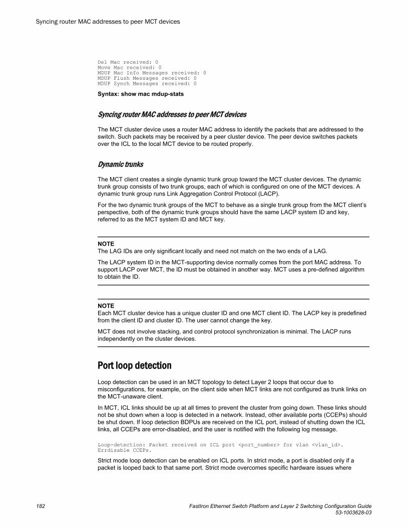
Del Mac received: 0Move Mac received: 0MDUP Mac Info Messages received: 0MDUP Flush Messages received: 0MDUP Synch Messages received: 0Syntax: show mac mdup-stats
Syncing router MAC addresses to peer MCT devices
The MCT cluster device uses a router MAC address to identify the packets that are addressed to theswitch. Such packets may be received by a peer cluster device. The peer device switches packetsover the ICL to the local MCT device to be routed properly.
Dynamic trunks
The MCT client creates a single dynamic trunk group toward the MCT cluster devices. The dynamictrunk group consists of two trunk groups, each of which is configured on one of the MCT devices. Adynamic trunk group runs Link Aggregation Control Protocol (LACP).
For the two dynamic trunk groups of the MCT to behave as a single trunk group from the MCT client’sperspective, both of the dynamic trunk groups should have the same LACP system ID and key,referred to as the MCT system ID and MCT key.
NOTEThe LAG IDs are only significant locally and need not match on the two ends of a LAG.
The LACP system ID in the MCT-supporting device normally comes from the port MAC address. Tosupport LACP over MCT, the ID must be obtained in another way. MCT uses a pre-defined algorithmto obtain the ID.
NOTEEach MCT cluster device has a unique cluster ID and one MCT client ID. The LACP key is predefinedfrom the client ID and cluster ID. The user cannot change the key.
MCT does not involve stacking, and control protocol synchronization is minimal. The LACP runsindependently on the cluster devices.
Port loop detectionLoop detection can be used in an MCT topology to detect Layer 2 loops that occur due tomisconfigurations, for example, on the client side when MCT links are not configured as trunk links onthe MCT-unaware client.
In MCT, ICL links should be up at all times to prevent the cluster from going down. These links shouldnot be shut down when a loop is detected in a network. Instead, other available ports (CCEPs) shouldbe shut down. If loop detection BDPUs are received on the ICL port, instead of shutting down the ICLlinks, all CCEPs are error-disabled, and the user is notified with the following log message.
Loop-detection: Packet received on ICL port <port_number> for vlan <vlan_id>. Errdisable CCEPs.Strict mode loop detection can be enabled on ICL ports. In strict mode, a port is disabled only if apacket is looped back to that same port. Strict mode overcomes specific hardware issues where
Syncing router MAC addresses to peer MCT devices
182 FastIron Ethernet Switch Platform and Layer 2 Switching Configuration Guide53-1003628-03
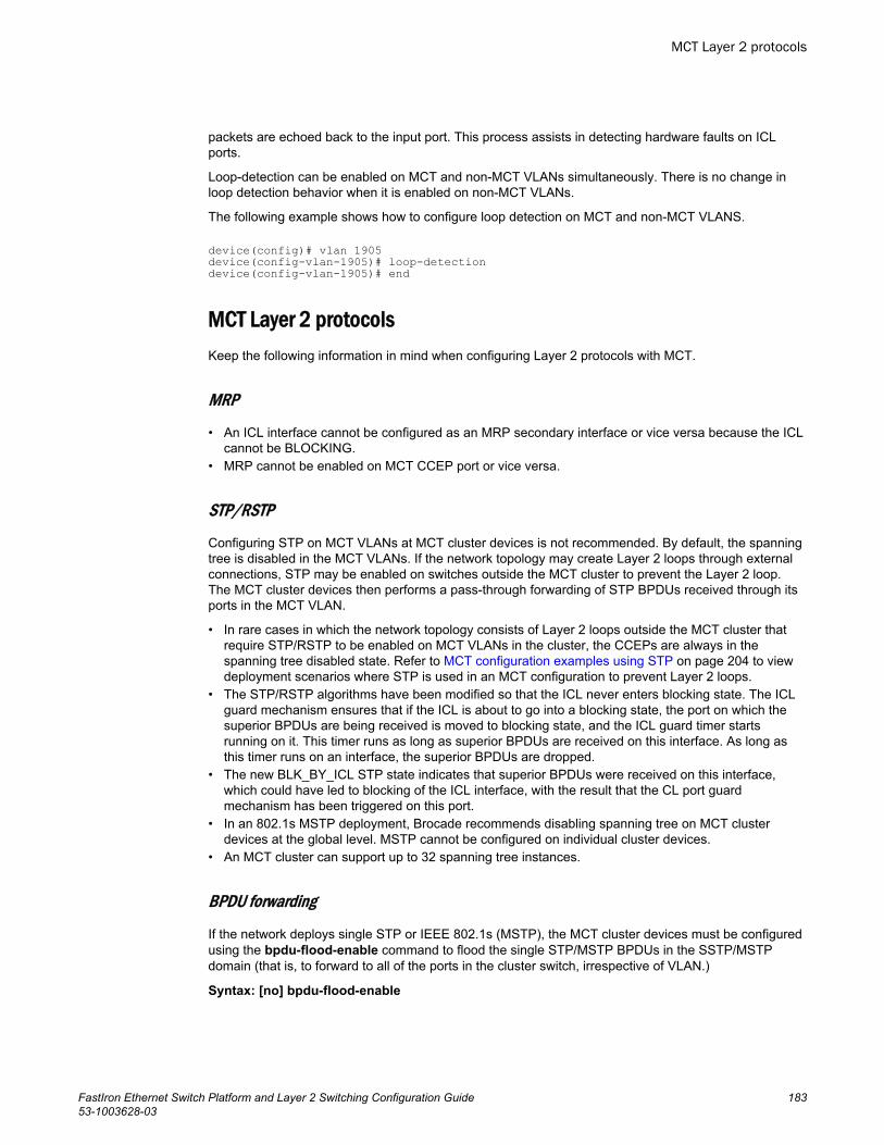
packets are echoed back to the input port. This process assists in detecting hardware faults on ICLports.
Loop-detection can be enabled on MCT and non-MCT VLANs simultaneously. There is no change inloop detection behavior when it is enabled on non-MCT VLANs.
The following example shows how to configure loop detection on MCT and non-MCT VLANS.
device(config)# vlan 1905 device(config-vlan-1905)# loop-detectiondevice(config-vlan-1905)# end
MCT Layer 2 protocolsKeep the following information in mind when configuring Layer 2 protocols with MCT.
MRP
• An ICL interface cannot be configured as an MRP secondary interface or vice versa because the ICLcannot be BLOCKING.
• MRP cannot be enabled on MCT CCEP port or vice versa.
STP/RSTP
Configuring STP on MCT VLANs at MCT cluster devices is not recommended. By default, the spanningtree is disabled in the MCT VLANs. If the network topology may create Layer 2 loops through externalconnections, STP may be enabled on switches outside the MCT cluster to prevent the Layer 2 loop.The MCT cluster devices then performs a pass-through forwarding of STP BPDUs received through itsports in the MCT VLAN.
• In rare cases in which the network topology consists of Layer 2 loops outside the MCT cluster thatrequire STP/RSTP to be enabled on MCT VLANs in the cluster, the CCEPs are always in thespanning tree disabled state. Refer to MCT configuration examples using STP on page 204 to viewdeployment scenarios where STP is used in an MCT configuration to prevent Layer 2 loops.
• The STP/RSTP algorithms have been modified so that the ICL never enters blocking state. The ICLguard mechanism ensures that if the ICL is about to go into a blocking state, the port on which thesuperior BPDUs are being received is moved to blocking state, and the ICL guard timer startsrunning on it. This timer runs as long as superior BPDUs are received on this interface. As long asthis timer runs on an interface, the superior BPDUs are dropped.
• The new BLK_BY_ICL STP state indicates that superior BPDUs were received on this interface,which could have led to blocking of the ICL interface, with the result that the CL port guardmechanism has been triggered on this port.
• In an 802.1s MSTP deployment, Brocade recommends disabling spanning tree on MCT clusterdevices at the global level. MSTP cannot be configured on individual cluster devices.
• An MCT cluster can support up to 32 spanning tree instances.
BPDU forwarding
If the network deploys single STP or IEEE 802.1s (MSTP), the MCT cluster devices must be configuredusing the bpdu-flood-enable command to flood the single STP/MSTP BPDUs in the SSTP/MSTPdomain (that is, to forward to all of the ports in the cluster switch, irrespective of VLAN.)
Syntax: [no] bpdu-flood-enable
MCT Layer 2 protocols
FastIron Ethernet Switch Platform and Layer 2 Switching Configuration Guide 18353-1003628-03
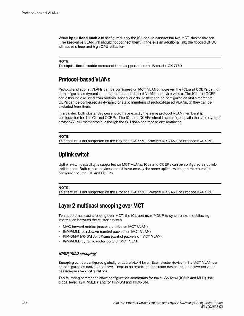
When bpdu-flood-enable is configured, only the ICL should connect the two MCT cluster devices.(The keep-alive VLAN link should not connect them.) If there is an additional link, the flooded BPDUwill cause a loop and high CPU utilization.
NOTEThe bpdu-flood-enable command is not supported on the Brocade ICX 7750.
Protocol-based VLANsProtocol and subnet VLANs can be configured on MCT VLANS; however, the ICL and CCEPs cannotbe configured as dynamic members of protocol-based VLANs (and vice versa). The ICL and CCEPcan either be excluded from protocol-based VLANs, or they can be configured as static members.CEPs can be configured as dynamic or static members of protocol-based VLANs, or they can beexcluded from them.
In a cluster, both cluster devices should have exactly the same protocol VLAN membershipconfiguration for the ICL and CCEPs. The ICL and CCEPs should be configured with the same type ofprotocol/VLAN membership, although the CLI does not impose any restriction.
NOTEThis feature is not supported on the Brocade ICX 7750, Brocade ICX 7450, or Brocade ICX 7250.
Uplink switchUplink switch capability is supported on MCT VLANs. ICLs and CCEPs can be configured as uplink-switch ports. Both cluster devices should have exactly the same uplink-switch port membershipsconfigured for the ICL and CCEPs.
NOTEThis feature is not supported on the Brocade ICX 7750, Brocade ICX 7450, or Brocade ICX 7250.
Layer 2 multicast snooping over MCTTo support multicast snooping over MCT, the ICL port uses MDUP to synchronize the followinginformation between the cluster devices:
• MAC-forward entries (mcache entries on MCT VLAN)• IGMP/MLD Join/Leave (control packets on MCT VLAN)• PIM-SM/PIM6-SM Join/Prune (control packets on MCT VLAN)• IGMP/MLD dynamic router ports on MCT VLAN
IGMP/MLD snooping
Snooping can be configured globally or at the VLAN level. Each cluster device in the MCT VLAN canbe configured as active or passive. There is no restriction for cluster devices to run active-active orpassive-passive configurations.
The following commands show configuration commands for the VLAN level (IGMP and MLD), theglobal level (IGMP/MLD), and for PIM-SM and PIM6-SM.
Protocol-based VLANs
184 FastIron Ethernet Switch Platform and Layer 2 Switching Configuration Guide53-1003628-03
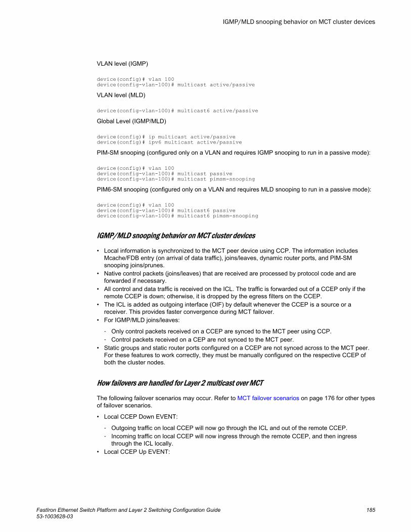
VLAN level (IGMP)
device(config)# vlan 100device(config-vlan-100)# multicast active/passiveVLAN level (MLD)
device(config-vlan-100)# multicast6 active/passiveGlobal Level (IGMP/MLD)
device(config)# ip multicast active/passivedevice(config)# ipv6 multicast active/passivePIM-SM snooping (configured only on a VLAN and requires IGMP snooping to run in a passive mode):
device(config)# vlan 100 device(config-vlan-100)# multicast passivedevice(config-vlan-100)# multicast pimsm-snoopingPIM6-SM snooping (configured only on a VLAN and requires MLD snooping to run in a passive mode):
device(config)# vlan 100 device(config-vlan-100)# multicast6 passivedevice(config-vlan-100)# multicast6 pimsm-snooping
IGMP/MLD snooping behavior on MCT cluster devices
• Local information is synchronized to the MCT peer device using CCP. The information includesMcache/FDB entry (on arrival of data traffic), joins/leaves, dynamic router ports, and PIM-SMsnooping joins/prunes.
• Native control packets (joins/leaves) that are received are processed by protocol code and areforwarded if necessary.
• All control and data traffic is received on the ICL. The traffic is forwarded out of a CCEP only if theremote CCEP is down; otherwise, it is dropped by the egress filters on the CCEP.
• The ICL is added as outgoing interface (OIF) by default whenever the CCEP is a source or areceiver. This provides faster convergence during MCT failover.
• For IGMP/MLD joins/leaves:
‐ Only control packets received on a CCEP are synced to the MCT peer using CCP.‐ Control packets received on a CEP are not synced to the MCT peer.
• Static groups and static router ports configured on a CCEP are not synced across to the MCT peer.For these features to work correctly, they must be manually configured on the respective CCEP ofboth the cluster nodes.
How failovers are handled for Layer 2 multicast over MCT
The following failover scenarios may occur. Refer to MCT failover scenarios on page 176 for other typesof failover scenarios.
• Local CCEP Down EVENT:
‐ Outgoing traffic on local CCEP will now go through the ICL and out of the remote CCEP.‐ Incoming traffic on local CCEP will now ingress through the remote CCEP, and then ingress
through the ICL locally.• Local CCEP Up EVENT:
IGMP/MLD snooping behavior on MCT cluster devices
FastIron Ethernet Switch Platform and Layer 2 Switching Configuration Guide 18553-1003628-03
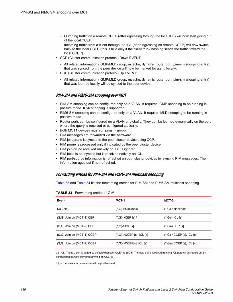
‐ Outgoing traffic on a remote CCEP (after egressing through the local ICL) will now start going outof the local CCEP.
‐ Incoming traffic from a client through the ICL (after ingressing on remote CCEP) will now switchback to the local CCEP (this is true only if the client trunk hashing sends the traffic toward thelocal CCEP).
• CCP (Cluster communication protocol) Down EVENT:
‐ All related information (IGMP/MLD group, mcache, dynamic router port, pim-sm snooping entry)that was synced from the peer device will now be marked for aging locally.
• CCP (Cluster communication protocol) Up EVENT:
‐ All related information (IGMP/MLD group, mcache, dynamic router port, pim-sm snooping entry)that was learned locally will be synced to the peer device.
PIM-SM and PIM6-SM snooping over MCT
• PIM-SM snooping can be configured only on a VLAN. It requires IGMP snooping to be running inpassive mode. IPv6 snooping is supported.
• PIM6-SM snooping can be configured only on a VLAN. It requires MLD snooping to be running inpassive mode.
• Router ports can be configured on a VLAN or globally. They can be learned dynamically on the portwhere the query is received or configured statically.
• Both MCT1 devices must run pimsm-snoop.• PIM messages are forwarded via the hardware.• PIM join/prune is synced to the peer cluster device using CCP.• PIM prune is processed only if indicated by the peer cluster device.• PIM join/prune received natively on ICL is ignored.• PIM hello is not synced but is received natively on ICL.• PIM port/source information is refreshed on both cluster devices by syncing PIM messages. The
information ages out if not refreshed.
Forwarding entries for PIM-SM and PIM6-SM multicast snooping
Table 33 and Table 34 list the forwarding entries for PIM-SM and PIM6-SM multicast snooping.
Forwarding entries (*,G) aTABLE 33
Event MCT-1 MCT-2
No-Join (*,G)->blackhole (*,G)->blackhole
(S,G) Join on (MCT-1) CEP (*,G)->CEP [s] b (*,G)->ICL [s]
(S,G) Join on (MCT-2) CEP (*,G)->ICL [s] (*,G)->CEP [s]
(S,G) Join on (MCT-1) CCEP (*,G)->CCEP [s], ICL [s] (*,G)->CCEP [s], ICL [s]
(S,G) Join on (MCT-2) CCEP (*,G)->CCEP[s], ICL [s] (*,G)->CCEP [s], ICL [s]
a.) *ICL: The ICL port is added as default whenever CCEP is in OIF. The data traffic received from the ICL port will be filtered out byegress filters dynamically programmed on CCEPs.
b.) [s]: denotes sources maintained on port hash-list.
PIM-SM and PIM6-SM snooping over MCT
186 FastIron Ethernet Switch Platform and Layer 2 Switching Configuration Guide53-1003628-03
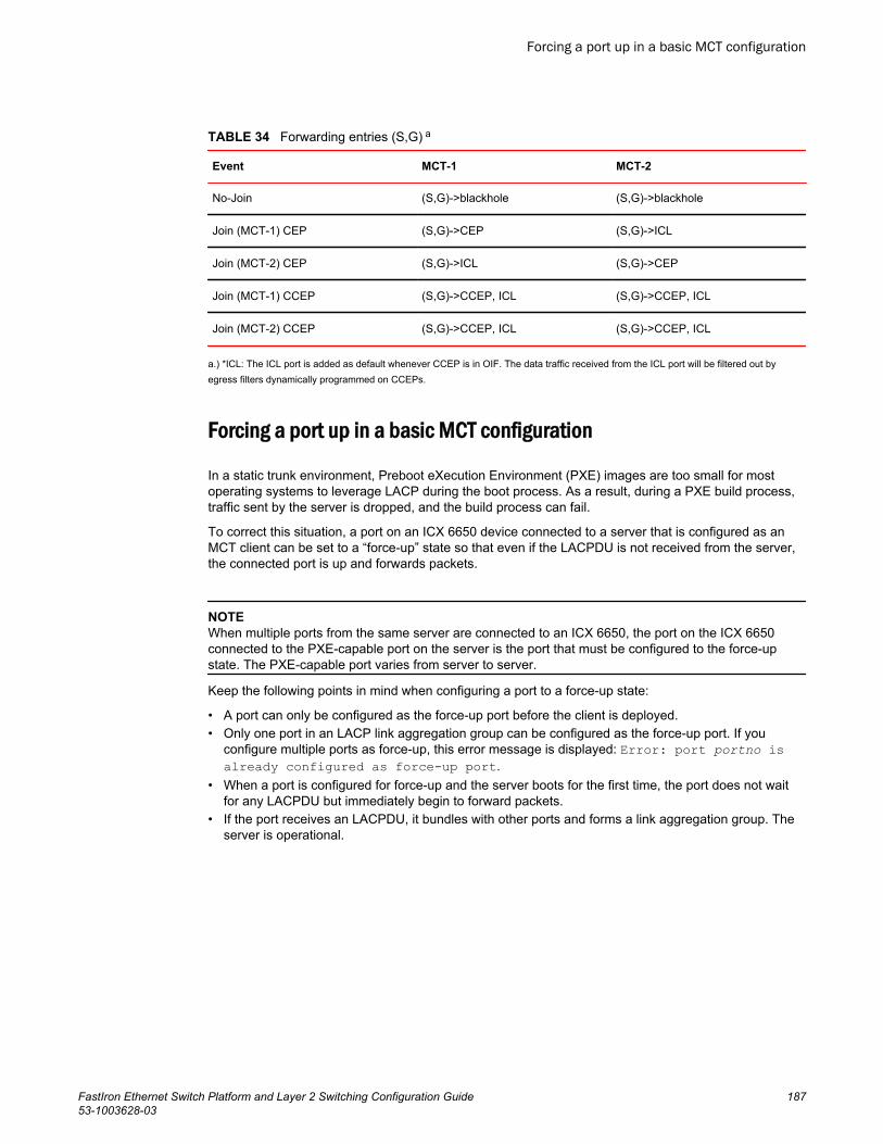
Forwarding entries (S,G) aTABLE 34
Event MCT-1 MCT-2
No-Join (S,G)->blackhole (S,G)->blackhole
Join (MCT-1) CEP (S,G)->CEP (S,G)->ICL
Join (MCT-2) CEP (S,G)->ICL (S,G)->CEP
Join (MCT-1) CCEP (S,G)->CCEP, ICL (S,G)->CCEP, ICL
Join (MCT-2) CCEP (S,G)->CCEP, ICL (S,G)->CCEP, ICL
a.) *ICL: The ICL port is added as default whenever CCEP is in OIF. The data traffic received from the ICL port will be filtered out byegress filters dynamically programmed on CCEPs.
Forcing a port up in a basic MCT configuration
In a static trunk environment, Preboot eXecution Environment (PXE) images are too small for mostoperating systems to leverage LACP during the boot process. As a result, during a PXE build process,traffic sent by the server is dropped, and the build process can fail.
To correct this situation, a port on an ICX 6650 device connected to a server that is configured as anMCT client can be set to a “force-up” state so that even if the LACPDU is not received from the server,the connected port is up and forwards packets.
NOTEWhen multiple ports from the same server are connected to an ICX 6650, the port on the ICX 6650connected to the PXE-capable port on the server is the port that must be configured to the force-upstate. The PXE-capable port varies from server to server.
Keep the following points in mind when configuring a port to a force-up state:
• A port can only be configured as the force-up port before the client is deployed.• Only one port in an LACP link aggregation group can be configured as the force-up port. If you
configure multiple ports as force-up, this error message is displayed: Error: port portno isalready configured as force-up port.
• When a port is configured for force-up and the server boots for the first time, the port does not waitfor any LACPDU but immediately begin to forward packets.
• If the port receives an LACPDU, it bundles with other ports and forms a link aggregation group. Theserver is operational.
Forcing a port up in a basic MCT configuration
FastIron Ethernet Switch Platform and Layer 2 Switching Configuration Guide 18753-1003628-03
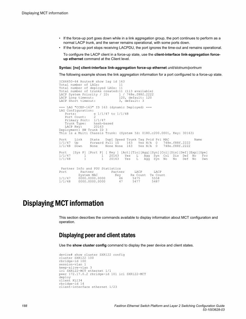
• If the force-up port goes down while in a link aggregation group, the port continues to perform as anormal LACP trunk, and the server remains operational, with some ports down.
• If the force-up port stops receiving LACPDU, the port ignores the time-out and remains operational.
To configure the LACP client in a force-up state, use the client-interface link-aggregation force-up ethernet command at the Client level.
Syntax: [no] client-interface link-aggregation force-up ethernet unit/slotnum/portnum
The following example shows the link aggregation information for a port configured to a force-up state.
ICX6650-64 Router# show lag id 163Total number of LAGs: 11Total number of deployed LAGs: 11Total number of trunks created:11 (113 available)LACP System Priority / ID: 1 / 748e.f88f.2222LACP Long timeout: 120, default: 120LACP Short timeout: 3, default: 3=== LAG "CCEP-163" ID 163 (dynamic Deployed) ===LAG Configuration: Ports: e 1/1/47 to 1/1/48 Port Count: 2 Primary Port: 1/1/47 Trunk Type: hash-based LACP Key: 20163Deployment: HW Trunk ID 3This is a Multi Chassis Trunk: (System Id: 0180.c200.0001, Key: 30163)Port Link State Dupl Speed Trunk Tag Pvid Pri MAC Name1/1/47 Up Forward Full 1G 163 Yes N/A 0 748e.f88f.2222 1/1/48 Down None None None 163 Yes N/A 0 748e.f88f.2222 Port [Sys P] [Port P] [ Key ] [Act][Tio][Agg][Syn][Col][Dis][Def][Exp][Ope]1/1/47 1 1 20163 Yes L Agg Syn Col Dis Def No Frc1/1/48 1 1 20163 Yes L Agg Syn No No Def No Dwn
Partner Info and PDU Statistics Port Partner Partner LACP LACP System MAC Key Rx Count Tx Count 1/1/47 0000.0000.0000 46 5475 55581/1/48 0000.0000.0000 47 5477 5487
Displaying MCT informationThis section describes the commands available to display information about MCT configuration andoperation.
Displaying peer and client statesUse the show cluster config command to display the peer device and client states.
device# show cluster SXR122 configcluster SXR122 100rbridge-id 100session-vlan 1keep-alive-vlan 3icl SXR122-MCT ethernet 1/1peer 172.17.0.2 rbridge-id 101 icl SXR122-MCTdeployclient KL134rbridge-id 14client-interface ethernet 1/23
Displaying MCT information
188 FastIron Ethernet Switch Platform and Layer 2 Switching Configuration Guide53-1003628-03
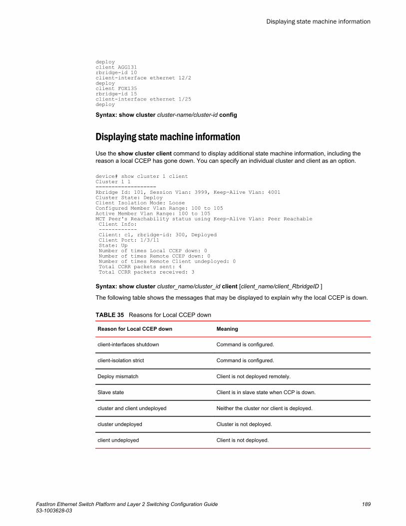
deployclient AGG131rbridge-id 10client-interface ethernet 12/2deployclient FOX135rbridge-id 15client-interface ethernet 1/25deploySyntax: show cluster cluster-name/cluster-id config
Displaying state machine informationUse the show cluster client command to display additional state machine information, including thereason a local CCEP has gone down. You can specify an individual cluster and client as an option.
device# show cluster 1 clientCluster 1 1===================Rbridge Id: 101, Session Vlan: 3999, Keep-Alive Vlan: 4001Cluster State: DeployClient Isolation Mode: LooseConfigured Member Vlan Range: 100 to 105 Active Member Vlan Range: 100 to 105 MCT Peer's Reachability status using Keep-Alive Vlan: Peer Reachable Client Info: ------------ Client: c1, rbridge-id: 300, Deployed Client Port: 1/3/11 State: Up Number of times Local CCEP down: 0 Number of times Remote CCEP down: 0 Number of times Remote Client undeployed: 0 Total CCRR packets sent: 4 Total CCRR packets received: 3
Syntax: show cluster cluster_name/cluster_id client [client_name/client_RbridgeID ]
The following table shows the messages that may be displayed to explain why the local CCEP is down.
Reasons for Local CCEP down TABLE 35
Reason for Local CCEP down Meaning
client-interfaces shutdown Command is configured.
client-isolation strict Command is configured.
Deploy mismatch Client is not deployed remotely.
Slave state Client is in slave state when CCP is down.
cluster and client undeployed Neither the cluster nor client is deployed.
cluster undeployed Cluster is not deployed.
client undeployed Client is not deployed.
Displaying state machine information
FastIron Ethernet Switch Platform and Layer 2 Switching Configuration Guide 18953-1003628-03
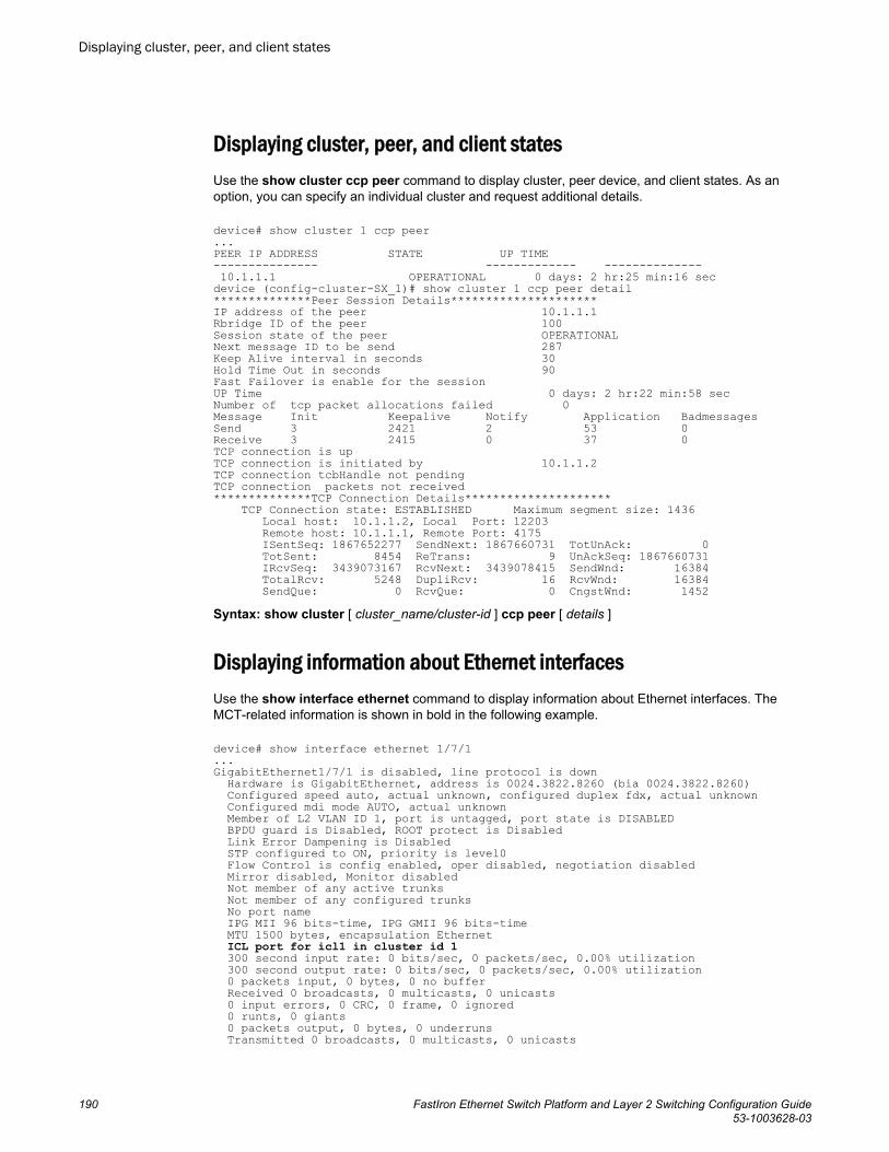
Displaying cluster, peer, and client statesUse the show cluster ccp peer command to display cluster, peer device, and client states. As anoption, you can specify an individual cluster and request additional details.
device# show cluster 1 ccp peer...PEER IP ADDRESS STATE UP TIME--------------- ------------- -------------- 10.1.1.1 OPERATIONAL 0 days: 2 hr:25 min:16 sec device (config-cluster-SX_1)# show cluster 1 ccp peer detail**************Peer Session Details*********************IP address of the peer 10.1.1.1Rbridge ID of the peer 100Session state of the peer OPERATIONALNext message ID to be send 287Keep Alive interval in seconds 30Hold Time Out in seconds 90Fast Failover is enable for the sessionUP Time 0 days: 2 hr:22 min:58 secNumber of tcp packet allocations failed 0Message Init Keepalive Notify Application BadmessagesSend 3 2421 2 53 0 Receive 3 2415 0 37 0 TCP connection is upTCP connection is initiated by 10.1.1.2TCP connection tcbHandle not pendingTCP connection packets not received**************TCP Connection Details********************* TCP Connection state: ESTABLISHED Maximum segment size: 1436 Local host: 10.1.1.2, Local Port: 12203 Remote host: 10.1.1.1, Remote Port: 4175 ISentSeq: 1867652277 SendNext: 1867660731 TotUnAck: 0 TotSent: 8454 ReTrans: 9 UnAckSeq: 1867660731 IRcvSeq: 3439073167 RcvNext: 3439078415 SendWnd: 16384 TotalRcv: 5248 DupliRcv: 16 RcvWnd: 16384 SendQue: 0 RcvQue: 0 CngstWnd: 1452Syntax: show cluster [ cluster_name/cluster-id ] ccp peer [ details ]
Displaying information about Ethernet interfacesUse the show interface ethernet command to display information about Ethernet interfaces. TheMCT-related information is shown in bold in the following example.
device# show interface ethernet 1/7/1...GigabitEthernet1/7/1 is disabled, line protocol is down Hardware is GigabitEthernet, address is 0024.3822.8260 (bia 0024.3822.8260) Configured speed auto, actual unknown, configured duplex fdx, actual unknown Configured mdi mode AUTO, actual unknown Member of L2 VLAN ID 1, port is untagged, port state is DISABLED BPDU guard is Disabled, ROOT protect is Disabled Link Error Dampening is Disabled STP configured to ON, priority is level0 Flow Control is config enabled, oper disabled, negotiation disabled Mirror disabled, Monitor disabled Not member of any active trunks Not member of any configured trunks No port name IPG MII 96 bits-time, IPG GMII 96 bits-time MTU 1500 bytes, encapsulation Ethernet ICL port for icl1 in cluster id 1 300 second input rate: 0 bits/sec, 0 packets/sec, 0.00% utilization 300 second output rate: 0 bits/sec, 0 packets/sec, 0.00% utilization 0 packets input, 0 bytes, 0 no buffer Received 0 broadcasts, 0 multicasts, 0 unicasts 0 input errors, 0 CRC, 0 frame, 0 ignored 0 runts, 0 giants 0 packets output, 0 bytes, 0 underruns Transmitted 0 broadcasts, 0 multicasts, 0 unicasts
Displaying cluster, peer, and client states
190 FastIron Ethernet Switch Platform and Layer 2 Switching Configuration Guide53-1003628-03
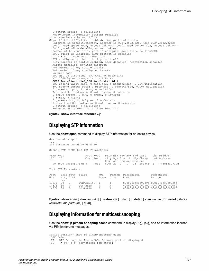
0 output errors, 0 collisions Relay Agent Information option: Disabledshow interface ethernet 1/7/3GigabitEthernet1/7/3 is disabled, line protocol is down Hardware is GigabitEthernet, address is 0024.3822.8262 (bia 0024.3822.8262) Configured speed auto, actual unknown, configured duplex fdx, actual unknown Configured mdi mode AUTO, actual unknown Member of L2 VLAN ID 1, port is untagged, port state is DISABLED BPDU guard is Disabled, ROOT protect is Disabled Link Error Dampening is Disabled STP configured to ON, priority is level0 Flow Control is config enabled, oper disabled, negotiation disabled Mirror disabled, Monitor disabled Not member of any active trunks Not member of any configured trunks No port name IPG MII 96 bits-time, IPG GMII 96 bits-time MTU 1500 bytes, encapsulation Ethernet CCEP for client c149_150 in cluster id 1 300 second input rate: 0 bits/sec, 0 packets/sec, 0.00% utilization 300 second output rate: 0 bits/sec, 0 packets/sec, 0.00% utilization 0 packets input, 0 bytes, 0 no buffer Received 0 broadcasts, 0 multicasts, 0 unicasts 0 input errors, 0 CRC, 0 frame, 0 ignored 0 runts, 0 giants 0 packets output, 0 bytes, 0 underruns Transmitted 0 broadcasts, 0 multicasts, 0 unicasts 0 output errors, 0 collisions Relay Agent Information option: DisabledSyntax: show interface ethernet x/y
Displaying STP informationUse the show span command to display STP information for an entire device.device# show span...STP instance owned by VLAN 90Global STP (IEEE 802.1D) Parameters:VLAN Root Root Root Prio Max He- Ho- Fwd Last Chg Bridge ID ID Cost Port rity Age llo ld dly Chang cnt Address Hex sec sec sec sec sec 90 8000748ef8f9739d 0 Root 8000 20 2 1 15 259968 1 748ef8f9739dPort STP Parameters: Port Prio Path State Fwd Design Designated Designated Num rity Cost Trans Cost Root Bridge Hex 1/2/1 80 1 FORWARDING 1 0 8000748ef8f9739d 8000748ef8f9739d 1/3/5 80 0 DISABLED 0 0 0000000000000000 0000000000000000 1/3/6 80 0 DISABLED 0 0 0000000000000000 0000000000000000
Syntax: show span [ vlan vlan-id ] | [ pvst-mode ] |[ num ] | [ detail [ vlan vlan-id [ Ethernet [ stack-unit/slotnum/] portnum ] | num] ]
Displaying information for multicast snoopingUse the show ip pimsm-snooping cache command to display (*,g), (s,g) and oif information learnedvia PIM join/prune messages.
Device(config)# show ip pimsm-snooping cache OIF Info: TR - OIF Belongs to Trunk/LAG, Primary port is displayed SG - (*,g)/(s,g) downstream fsm state:
Displaying STP information
FastIron Ethernet Switch Platform and Layer 2 Switching Configuration Guide 19153-1003628-03
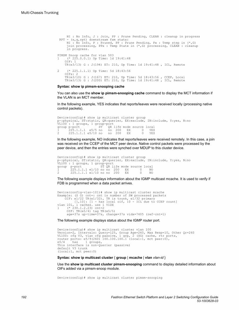
NI : No Info, J : Join, PP : Prune Pending, CLEAN : cleanup in progress RPT - (s,g,rpt) downstream fsm state: NI : No Info, P : Pruned, PP : Prune Pending, Px : Temp step in (*,G) join processing, PPx : Temp State in (*,G) processing, CLEAN : cleanup in progress.PIMSM Snoop cache for vlan 5031 (* 225.0.0.1) Up Time: 1d 19:41:48 OIF: 1 TR(e3/13) G : J(194) ET: 210, Up Time: 1d 19:41:48 , ICL, Remote2 (* 225.1.1.1) Up Time: 5d 18:43:56 OIFs: 2 TR(e3/10) G : J(167) ET: 210, Up Time: 5d 18:43:56 , CCEP, Local TR(e3/13) G : J(200) ET: 210, Up Time: 1d 19:41:48 , ICL, RemoteSyntax: show ip pimsm-snooping cache
You can also use the show ip pimsm-snooping cache command to display the MCT information ifthe VLAN is an MCT member.
In the following example, YES indicates that reports/leaves were received locally (processing nativecontrol packets).
Device(config)# show ip multicast cluster group p-:physical, ST:static, QR:querier, EX:exclude, IN:include, Y:yes, N:noVL100 : 1 groups, 1 group-portgroup p-port ST QR life mode source local1 225.1.1.1 e5/5 no no 200 EX 0 YES2 225.1.1.1 e5/10 no no 200 EX 0 YESIn the following example, NO indicates that reports/leaves were received remotely. In this case, a joinwas received on the CCEP of the MCT peer device. Native control packets were processed by thepeer device, and then the entries were synched over MDUP to this cluster device.
Device(config)# show ip multicast cluster groupp-:physical, ST:static, QR:querier, EX:exclude, IN:include, Y:yes, N:noVL100 : 1 groups, 1 group-portgroup p-port ST QR life mode source local1 225.1.1.1 e1/10 no no 200 EX 0 NO2 225.1.1.1 e1/10 no no 200 EX 0 NOThe following example displays information about the IGMP multicast mcache. It is used to verify ifFDB is programmed when a data packet arrives.
Device(config-vlan-101)# show ip multicast cluster mcacheExample: (S G) cnt=: cnt is number of SW processed packets OIF: e1/22 TR(e1/32), TR is trunk, e1/32 primary [1,10]: [1 - has local oif, 10 - ICL due to CCEP count]vlan 101, 1 caches. use 1 VIDX1 (* 230.1.2.23) cnt=2 OIF: TR(e5/4) tag TR(e5/5) age=37s up-time=37s, change=37s vidx=7405 (ref-cnt=1)The following example displays status about the IGMP router port.
Device(config)# show ip multicast cluster vlan 100Version=2, Intervals: Query=125, Group Age=260, Max Resp=10, Other Qr=260VL100: cfg V3, vlan cfg passive, 1 grp, 2 (SG) cache, rtr ports,router ports: e5/9(260) 100.100.100.1 (local:1, mct peer:0),e5/4 has 1 groups,This interface is non-Querier (passive)default V3 trunk(local:1, mct peer:0) Syntax: show ip multicast cluster { group | mcache | vlan vlan-id }
Use the show ip multicast cluster pimsm-snooping command to display detailed information aboutOIFs added via a pimsm-snoop module.
Device(config)# show ip multicast cluster pimsm-snooping
Multi-Chassis Trunking
192 FastIron Ethernet Switch Platform and Layer 2 Switching Configuration Guide53-1003628-03
Example: Port: 1/7/3 (age, port type, ref_count, owner flag, pruned flag)source: 1/7/3 has 1 src: 11.0.0.5(age, ref_count, owner flag, pruned flag)owner flag: 0x0: local, 0x1 remote cep, 0x2 remote ccepvlan 100, has 1 caches.1 (* 224.10.10.10) has 2 pim join ports out of 2 OIF1/7/3 (1,ICL), 1/7/5 (1, CCEP)Syntax: show ip multicast cluster pimsm-snooping [ group | vlan ]
Refer to the FastIron Command Reference for information on show ipv6 multicast cache and otherMLD multicast commands.
MCT configuration examplesThe examples in this section show the topology and configuration for a single-level MCT deployment,VRRP/VRRP-E over MCT, OSPF over MCT and BGP over MCT.
Single-level MCT exampleThe following figure depicts a single-level MCT configuration. The clients can be server hosts ornetworking devices. The associated configuration follows.
NOTEThe LAG IDs are locally significant only and need not be matching on the two ends of a LAG.
MCT configuration examples
FastIron Ethernet Switch Platform and Layer 2 Switching Configuration Guide 19353-1003628-03
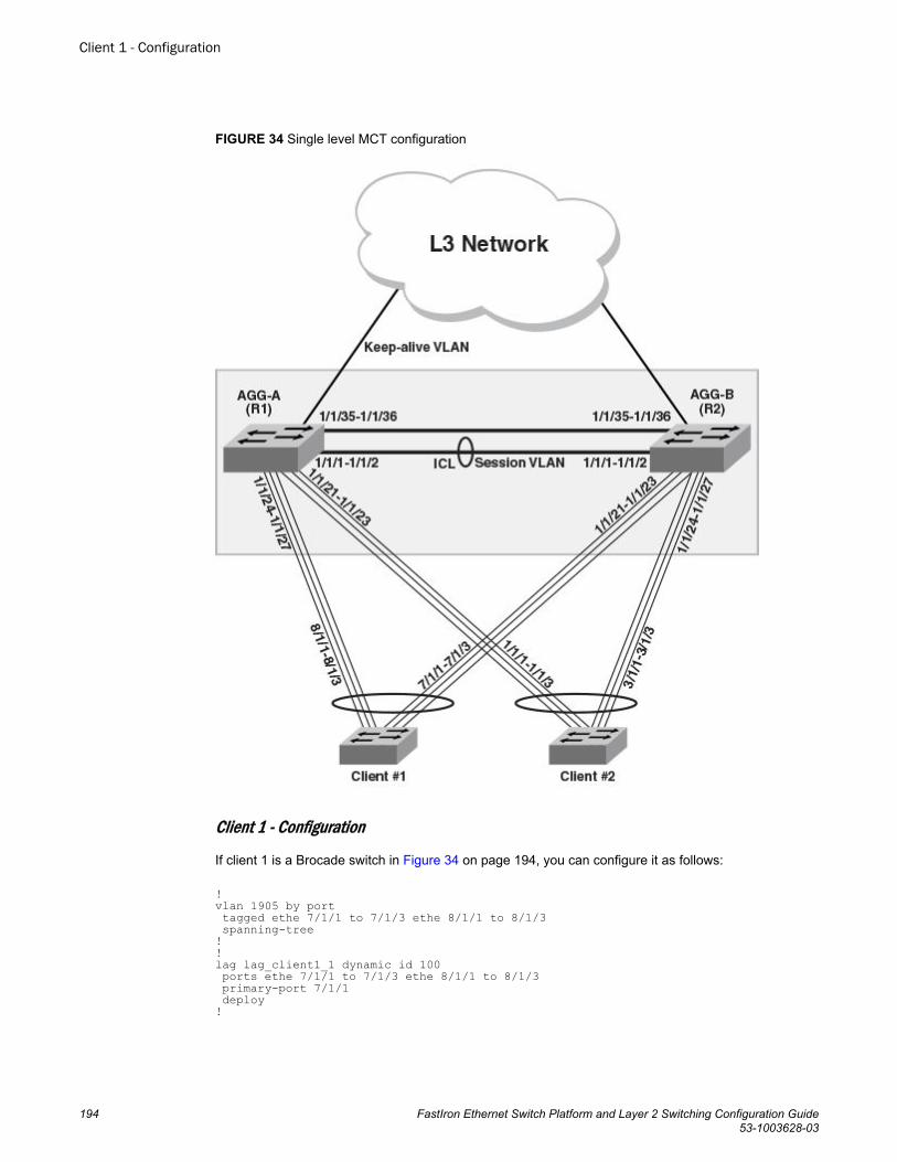
FIGURE 34 Single level MCT configuration
Client 1 - Configuration
If client 1 is a Brocade switch in Figure 34 on page 194, you can configure it as follows:
!vlan 1905 by port tagged ethe 7/1/1 to 7/1/3 ethe 8/1/1 to 8/1/3 spanning-tree!!lag lag_client1_1 dynamic id 100 ports ethe 7/1/1 to 7/1/3 ethe 8/1/1 to 8/1/3 primary-port 7/1/1 deploy!
Client 1 - Configuration
194 FastIron Ethernet Switch Platform and Layer 2 Switching Configuration Guide53-1003628-03
Client 2- Configuration
If client 2 is a Brocade switch in Figure 34 on page 194, you can configure it as follows:!vlan 1905 by port tagged ethe 1/1/1 to 1/1/3 ethe 3/1/1 to 3/1/3 spanning-tree!lag lag_client2_1 dynamic id 200 ports ethe 1/1/1 to 1/1/3 ethe 3/1/1 to 3/1/3 primary-port 1/1/1 deploy!
AGG-A (R1) - Configuration
This section presents the configuration for the AGG-A (R1) cluster device in Figure 34 on page 194.
lag lag_agg_a_1 static id 103 ports ethe 1/1/1 to 1/1/2 primary-port 1/1/1 deploy!lag lag_agg_a_2 dynamic id 104 ports ethe 1/1/24 to 1/1/27 primary-port 1/1/24 deploy!lag lag_agg_a_3 dynamic id 105 ports ethe 1/1/21 to 1/1/23 primary-port 1/1/21 deploy!vlan 2 name session-vlan by port tagged ethe 1/1/1 to 1/1/2 router-interface ve 2! vlan 3 name keep-alive-vlan by port tagged ethe 1/1/35-1/1/36 router-interface ve 3!vlan 1905 by port tagged ethe 1/1/24 to 1/1/27 ethe 1/1/21 ethe 1/1/23 ethe 1/1/1 to 1/1/2 !hostname R1!interface ve 2 ip address 10.1.1.1 255.255.255.0!interface ve 3 ip address 10.1.2.1 255.255.255.0!!cluster MCT1 1 rbridge-id 1 session-vlan 2 keep-alive-vlan 3 icl BH1 ethernet 1/1/1 peer 10.1.1.2 rbridge-id 2 icl BH1 deploy client client-1 rbridge-id 1901 client-interface ethe 1/1/24 deploy client client-2 rbridge-id 1902 client-interface ethe 1/1/21 deploy !
Client 2- Configuration
FastIron Ethernet Switch Platform and Layer 2 Switching Configuration Guide 19553-1003628-03
AGG-B (R2) - Configuration
This section presents the configuration for the AGG-B (R2) cluster device in Figure 34 on page 194.
lag lag_agg_b_1 static id 103 ports ethe 1/1/1 to 1/1/2 primary-port 1/1/1 deploy!lag lag_agg_b_2 dynamic id 105 ports ethe 1/1/24 to 1/1/27 primary-port 1/1/24 deploy!lag lag_agg_b_3 dynamic id 104 ports ethe 1/1/21 to 1/1/23 primary-port 1/1/21 deploy!vlan 2 name session-vlan by port tagged ethe 1/1/1 to 1/1/2 router-interface ve 2! vlan 3 by port tagged ethe 1/1/35-1/1/36 router-interface ve 3!! vlan 1905 by port tagged ethe 1/1/24 to 1/1/27 ethe 1/1/21 to 1/1/23 ethe 1/1/1 to 1/1/2 !hostname R2!interface ve 2 ip address 10.1.1.2 255.255.255.0!interface ve 3 ip address 10.1.2.2 255.255.255.0!cluster MCT1 1 rbridge-id 2 session-vlan 2 keep-alive-vlan 3 icl BH1 ethernet 1/1/1 peer 10.1.1.1 rbridge-id 1 icl BH1 deploy client client-1 rbridge-id 1901 client-interface ethe 1/1/21 deploy client client-2 rbridge-id 1902 client-interface ethe 1/1/24!
Two-level MCT exampleThe following figure depicts a two-level MCT configuration. The clients can be server hosts ornetworking devices. The associated configuration follows.
NOTEThe LAG IDs are locally significant only and need not be matching on the two ends of a LAG.
AGG-B (R2) - Configuration
196 FastIron Ethernet Switch Platform and Layer 2 Switching Configuration Guide53-1003628-03
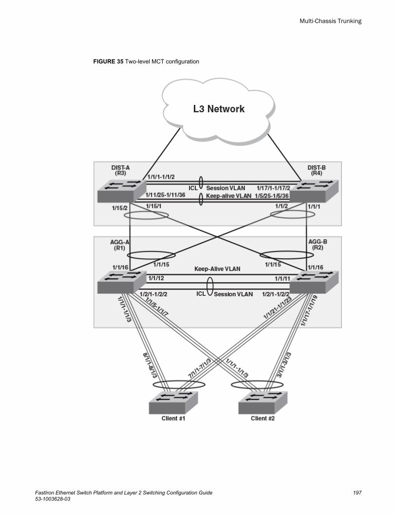
FIGURE 35 Two-level MCT configuration
Multi-Chassis Trunking
FastIron Ethernet Switch Platform and Layer 2 Switching Configuration Guide 19753-1003628-03
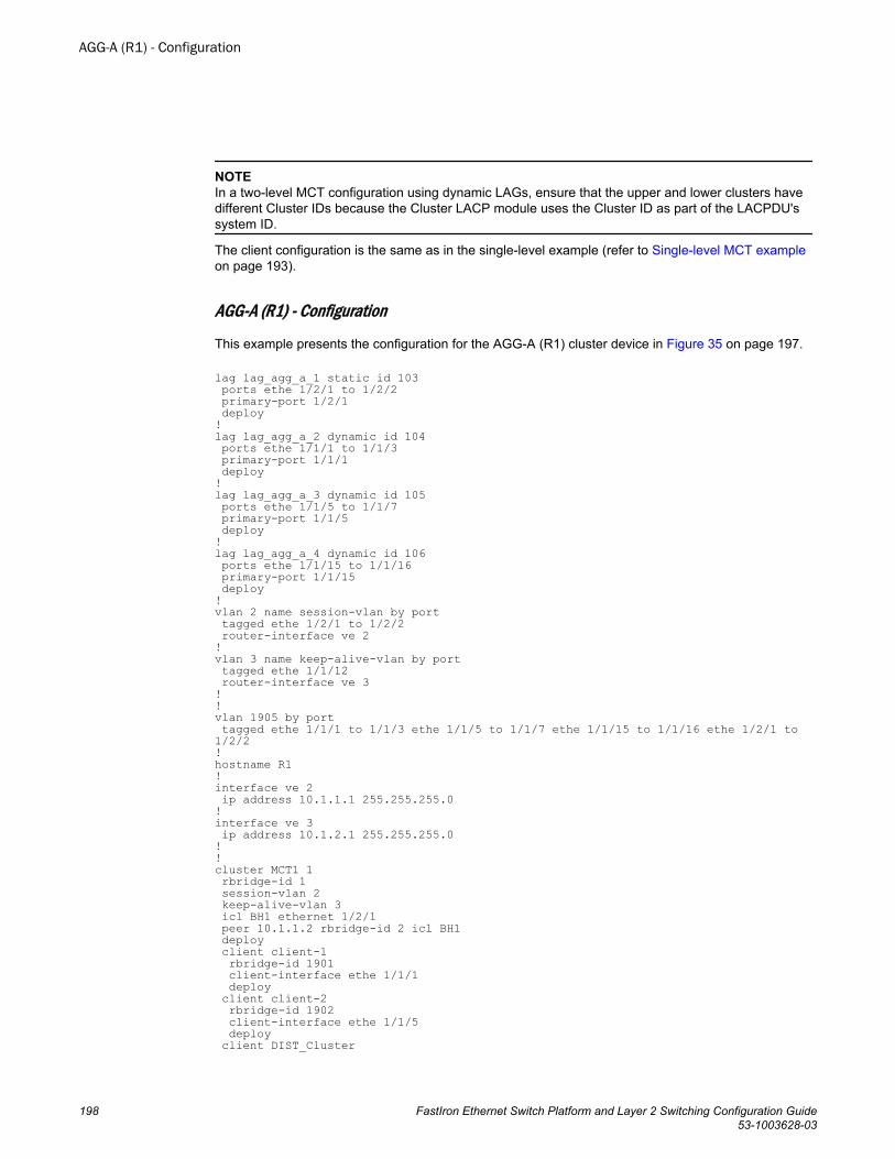
NOTEIn a two-level MCT configuration using dynamic LAGs, ensure that the upper and lower clusters havedifferent Cluster IDs because the Cluster LACP module uses the Cluster ID as part of the LACPDU'ssystem ID.
The client configuration is the same as in the single-level example (refer to Single-level MCT exampleon page 193).
AGG-A (R1) - Configuration
This example presents the configuration for the AGG-A (R1) cluster device in Figure 35 on page 197.
lag lag_agg_a_1 static id 103 ports ethe 1/2/1 to 1/2/2 primary-port 1/2/1 deploy!lag lag_agg_a_2 dynamic id 104 ports ethe 1/1/1 to 1/1/3 primary-port 1/1/1 deploy!lag lag_agg_a_3 dynamic id 105 ports ethe 1/1/5 to 1/1/7 primary-port 1/1/5 deploy!lag lag_agg_a_4 dynamic id 106 ports ethe 1/1/15 to 1/1/16 primary-port 1/1/15 deploy!vlan 2 name session-vlan by port tagged ethe 1/2/1 to 1/2/2 router-interface ve 2! vlan 3 name keep-alive-vlan by port tagged ethe 1/1/12 router-interface ve 3!! vlan 1905 by port tagged ethe 1/1/1 to 1/1/3 ethe 1/1/5 to 1/1/7 ethe 1/1/15 to 1/1/16 ethe 1/2/1 to 1/2/2 !hostname R1!interface ve 2 ip address 10.1.1.1 255.255.255.0!interface ve 3 ip address 10.1.2.1 255.255.255.0!!cluster MCT1 1 rbridge-id 1 session-vlan 2 keep-alive-vlan 3 icl BH1 ethernet 1/2/1 peer 10.1.1.2 rbridge-id 2 icl BH1 deploy client client-1 rbridge-id 1901 client-interface ethe 1/1/1 deploy client client-2 rbridge-id 1902 client-interface ethe 1/1/5 deploy client DIST_Cluster
AGG-A (R1) - Configuration
198 FastIron Ethernet Switch Platform and Layer 2 Switching Configuration Guide53-1003628-03
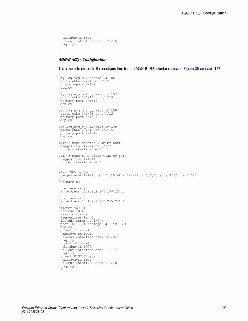
rbridge-id 1903 client-interface ethe 1/1/15 deploy !
AGG-B (R2) - Configuration
This example presents the configuration for the AGG-B (R2) cluster device in Figure 35 on page 197.
lag lag_agg_b_1 static id 106 ports ethe 1/2/1 to 1/2/2 primary-port 1/2/1 deploy!lag lag_agg_b_2 dynamic id 107 ports ethe 1/1/17 to 1/1/19 primary-port 1/1/17 deploy!lag lag_agg_b_3 dynamic id 108 ports ethe 1/1/21 to 1/1/23 primary-port 1/1/21 deploy!lag lag_agg_b_4 dynamic id 109 ports ethe 1/1/15 to 1/1/16 primary-port 1/1/15 deploy!vlan 2 name session-vlan by port tagged ethe 1/2/1 to 1/2/2 router-interface ve 2! vlan 3 name keep-alive-vlan by port tagged ethe 1/1/11 router-interface ve 3!! vlan 1905 by port tagged ethe 1/1/15 to 1/1/19 ethe 1/1/21 to 1/1/23 ethe 1/2/1 to 1/2/2 !hostname R2!interface ve 2 ip address 10.1.1.2 255.255.255.0!interface ve 3 ip address 10.1.2.2 255.255.255.0!cluster MCT1 1 rbridge-id 2 session-vlan 2 keep-alive-vlan 3 icl BH1 ethernet 1/2/1 peer 10.1.1.1 rbridge-id 1 icl BH1 deploy client client-1 rbridge-id 1901 client-interface ethe 1/1/21 deploy client client-2 rbridge-id 1902 client-interface ethe 1/1/17 deploy client DIST_Cluster rbridge-id 1903 client-interface ethe 1/1/15 deploy !
AGG-B (R2) - Configuration
FastIron Ethernet Switch Platform and Layer 2 Switching Configuration Guide 19953-1003628-03
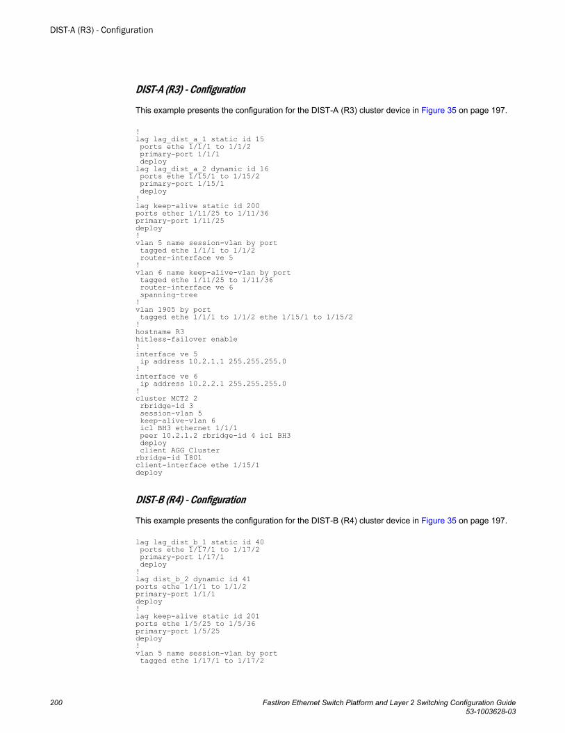
DIST-A (R3) - Configuration
This example presents the configuration for the DIST-A (R3) cluster device in Figure 35 on page 197.
!lag lag_dist_a_1 static id 15 ports ethe 1/1/1 to 1/1/2 primary-port 1/1/1 deploylag lag_dist_a_2 dynamic id 16 ports ethe 1/15/1 to 1/15/2 primary-port 1/15/1 deploy!lag keep-alive static id 200ports ether 1/11/25 to 1/11/36primary-port 1/11/25deploy!vlan 5 name session-vlan by port tagged ethe 1/1/1 to 1/1/2 router-interface ve 5!vlan 6 name keep-alive-vlan by port tagged ethe 1/11/25 to 1/11/36 router-interface ve 6 spanning-tree!vlan 1905 by port tagged ethe 1/1/1 to 1/1/2 ethe 1/15/1 to 1/15/2 !hostname R3hitless-failover enable!interface ve 5 ip address 10.2.1.1 255.255.255.0!interface ve 6 ip address 10.2.2.1 255.255.255.0!cluster MCT2 2 rbridge-id 3 session-vlan 5 keep-alive-vlan 6 icl BH3 ethernet 1/1/1 peer 10.2.1.2 rbridge-id 4 icl BH3 deploy client AGG_Clusterrbridge-id 1801client-interface ethe 1/15/1deploy
DIST-B (R4) - Configuration
This example presents the configuration for the DIST-B (R4) cluster device in Figure 35 on page 197.
lag lag_dist_b_1 static id 40 ports ethe 1/17/1 to 1/17/2 primary-port 1/17/1 deploy!lag dist_b_2 dynamic id 41ports ethe 1/1/1 to 1/1/2primary-port 1/1/1deploy!lag keep-alive static id 201ports ethe 1/5/25 to 1/5/36primary-port 1/5/25deploy!vlan 5 name session-vlan by port tagged ethe 1/17/1 to 1/17/2
DIST-A (R3) - Configuration
200 FastIron Ethernet Switch Platform and Layer 2 Switching Configuration Guide53-1003628-03
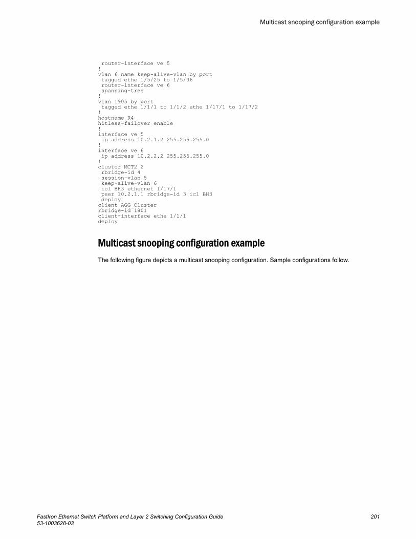
router-interface ve 5!vlan 6 name keep-alive-vlan by port tagged ethe 1/5/25 to 1/5/36 router-interface ve 6 spanning-tree!vlan 1905 by port tagged ethe 1/1/1 to 1/1/2 ethe 1/17/1 to 1/17/2 !hostname R4hitless-failover enable!interface ve 5 ip address 10.2.1.2 255.255.255.0!interface ve 6 ip address 10.2.2.2 255.255.255.0!cluster MCT2 2 rbridge-id 4 session-vlan 5 keep-alive-vlan 6 icl BH3 ethernet 1/17/1 peer 10.2.1.1 rbridge-id 3 icl BH3 deploy client AGG_Clusterrbridge-id 1801client-interface ethe 1/1/1deploy
Multicast snooping configuration exampleThe following figure depicts a multicast snooping configuration. Sample configurations follow.
Multicast snooping configuration example
FastIron Ethernet Switch Platform and Layer 2 Switching Configuration Guide 20153-1003628-03
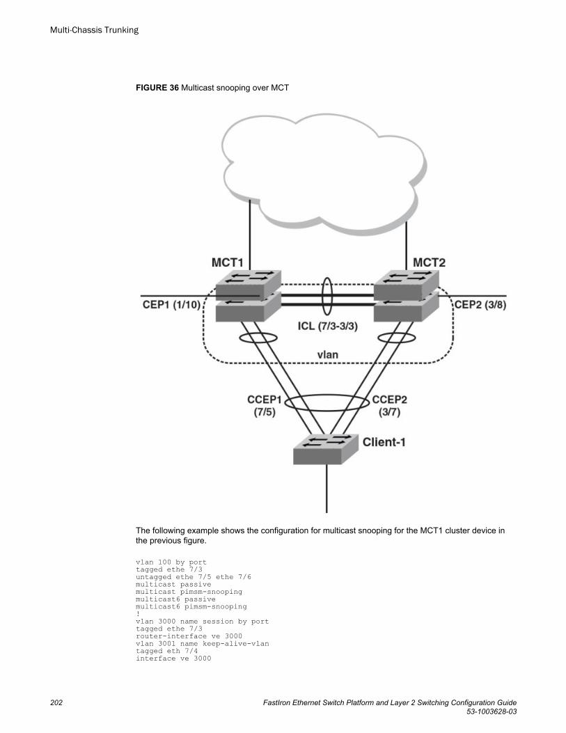
FIGURE 36 Multicast snooping over MCT
The following example shows the configuration for multicast snooping for the MCT1 cluster device inthe previous figure.
vlan 100 by porttagged ethe 7/3untagged ethe 7/5 ethe 7/6multicast passivemulticast pimsm-snoopingmulticast6 passivemulticast6 pimsm-snooping!vlan 3000 name session by porttagged ethe 7/3router-interface ve 3000vlan 3001 name keep-alive-vlantagged eth 7/4interface ve 3000
Multi-Chassis Trunking
202 FastIron Ethernet Switch Platform and Layer 2 Switching Configuration Guide53-1003628-03
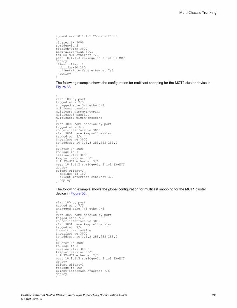
ip address 10.1.1.2 255.255.255.0!cluster SX 3000rbridge-id 2session-vlan 3000keep-alive-vlan 3001icl SX-MCT ethernet 7/3peer 10.1.1.3 rbridge-id 3 icl SX-MCTdeployclient client-1 rbridge-id 100 client-interface ethernet 7/5 deploy!The following example shows the configuration for multicast snooping for the MCT2 cluster device in Figure 36 .
!vlan 100 by porttagged ethe 3/3untagged ethe 3/7 ethe 3/8multicast passivemulticast pimsm-snoopingmulticast6 passivemulticast6 pimsm-snooping!vlan 3000 name session by porttagged ethe 3/3router-interface ve 3000vlan 3001 name keep-alive-vlantagged eth 3/4interface ve 3000ip address 10.1.1.3 255.255.255.0!cluster SX 3000rbridge-id 3session-vlan 3000keep-alive-vlan 3001icl SX-MCT ethernet 3/3peer 10.1.1.2 rbridge-id 2 icl SX-MCTdeployclient client-1 rbridge-id 100 client-interface ethernet 3/7 deploy!The following example shows the global configuration for multicast snooping for the MCT1 clusterdevice in Figure 36 .
vlan 100 by porttagged ethe 7/3untagged ethe 7/5 ethe 7/6!vlan 3000 name session by porttagged ethe 7/3router-interface ve 3000vlan 3001 name keep-alive-vlantagged eth 7/4ip multicast activeinterface ve 3000ip address 10.1.1.2 255.255.255.0!cluster SX 3000rbridge-id 2session-vlan 3000keep-alive-vlan 3001icl SX-MCT ethernet 7/3peer 10.1.1.3 rbridge-id 3 icl SX-MCTdeployclient client-1rbridge-id 100client-interface ethernet 7/5deploy!
Multi-Chassis Trunking
FastIron Ethernet Switch Platform and Layer 2 Switching Configuration Guide 20353-1003628-03
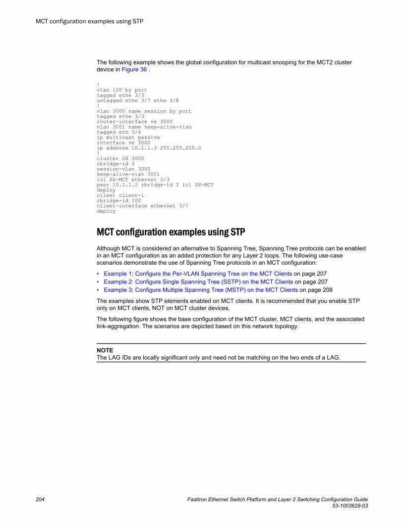
The following example shows the global configuration for multicast snooping for the MCT2 clusterdevice in Figure 36 .
!vlan 100 by porttagged ethe 3/3untagged ethe 3/7 ethe 3/8!vlan 3000 name session by porttagged ethe 3/3router-interface ve 3000vlan 3001 name keep-alive-vlantagged eth 3/4ip multicast passiveinterface ve 3000ip address 10.1.1.3 255.255.255.0!cluster SX 3000rbridge-id 3session-vlan 3000keep-alive-vlan 3001icl SX-MCT ethernet 3/3peer 10.1.1.2 rbridge-id 2 icl SX-MCTdeployclient client-1rbridge-id 100client-interface ethernet 3/7deploy
MCT configuration examples using STPAlthough MCT is considered an alternative to Spanning Tree, Spanning Tree protocols can be enabledin an MCT configuration as an added protection for any Layer 2 loops. The following use-casescenarios demonstrate the use of Spanning Tree protocols in an MCT configuration:
• Example 1: Configure the Per-VLAN Spanning Tree on the MCT Clients on page 207• Example 2: Configure Single Spanning Tree (SSTP) on the MCT Clients on page 207• Example 3: Configure Multiple Spanning Tree (MSTP) on the MCT Clients on page 208
The examples show STP elements enabled on MCT clients. It is recommended that you enable STPonly on MCT clients, NOT on MCT cluster devices.
The following figure shows the base configuration of the MCT cluster, MCT clients, and the associatedlink-aggregation. The scenarios are depicted based on this network topology.
NOTEThe LAG IDs are locally significant only and need not be matching on the two ends of a LAG.
MCT configuration examples using STP
204 FastIron Ethernet Switch Platform and Layer 2 Switching Configuration Guide53-1003628-03
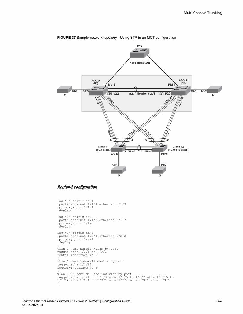
FIGURE 37 Sample network topology - Using STP in an MCT configuration
Router-1 configuration
!lag "1" static id 1 ports ethernet 1/1/1 ethernet 1/1/3 primary-port 1/1/1 deploylag "1" static id 2 ports ethernet 1/1/5 ethernet 1/1/7 primary-port 1/1/5 deploylag "1" static id 3 ports ethernet 1/2/1 ethernet 1/2/2 primary-port 1/2/1 deploy!vlan 2 name session-vlan by porttagged ethe 1/2/1 to 1/2/2router-interface ve 2!vlan 3 name keep-alive-vlan by porttagged ethe 1/1/12router-interface ve 3!vlan 1905 name MAC-scaling-vlan by porttagged ethe 1/1/1 to 1/1/3 ethe 1/1/5 to 1/1/7 ethe 1/1/15 to1/1/16 ethe 1/2/1 to 1/2/2 ethe 1/2/4 ethe 1/3/1 ethe 1/3/3!
Multi-Chassis Trunking
FastIron Ethernet Switch Platform and Layer 2 Switching Configuration Guide 20553-1003628-03
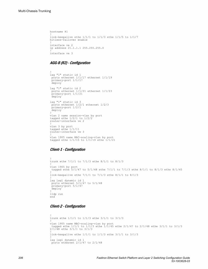
hostname R1!link-keepalive ethe 1/1/1 to 1/1/3 ethe 1/1/5 to 1/1/7hitless-failover enable!interface ve 2ip address 21.1.1.1 255.255.255.0!interface ve 3
AGG-B (R2) - Configuration
!lag "1" static id 1 ports ethernet 1/1/17 ethernet 1/1/19 primary-port 1/1/17 deploylag "1" static id 2 ports ethernet 1/1/21 ethernet 1/1/23 primary-port 1/1/21 deploylag "1" static id 3 ports ethernet 1/2/1 ethernet 1/2/3 primary-port 1/2/1 deploy!vlan 2 name session-vlan by porttagged ethe 1/2/1 to 1/2/2router-interface ve 2!vlan 3 by porttagged ethe 1/1/11router-interface ve 3!vlan 1905 name MAC-scaling-vlan by porttagged ethe 1/1/15 to 1/1/19 ethe 1/1/21
Client-1 - Configuration
!trunk ethe 7/1/1 to 7/1/3 ethe 8/1/1 to 8/1/3!vlan 1905 by port tagged ethe 5/1/47 to 5/1/48 ethe 7/1/1 to 7/1/3 ethe 8/1/1 to 8/1/3 ethe 8/1/45!link-keepalive ethe 7/1/1 to 7/1/3 ethe 8/1/1 to 8/1/3!lag lag1 dynamic id 1 ports ethernet 5/1/47 to 5/1/48 primary-port 5/1/47 deploy!lldp runend
Client-2 - Configuration
!trunk ethe 1/1/1 to 1/1/3 ethe 3/1/1 to 3/1/3!vlan 1905 name MAC-scaling-vlan by port tagged ethe 1/1/1 to 1/1/3 ethe 1/1/45 ethe 2/1/47 to 2/1/48 ethe 3/1/1 to 3/1/32/1/48 ethe 3/1/1 to 3/1/3!link-keepalive ethe 1/1/1 to 1/1/3 ethe 3/1/1 to 3/1/3!lag lag1 dynamic id 1 ports ethernet 2/1/47 to 2/1/48
Multi-Chassis Trunking
206 FastIron Ethernet Switch Platform and Layer 2 Switching Configuration Guide53-1003628-03
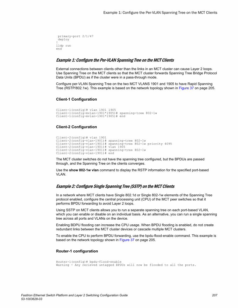
primary-port 2/1/47 deploy!lldp runend
Example 1: Configure the Per-VLAN Spanning Tree on the MCT Clients
External connections between clients other than the links in an MCT cluster can cause Layer 2 loops.Use Spanning Tree on the MCT clients so that the MCT cluster forwards Spanning Tree Bridge ProtocolData Units (BPDU) as if the cluster were in a pass-through mode.
Configure per-VLAN Spanning Tree on the two MCT VLANS 1901 and 1905 to have Rapid SpanningTree (RSTP/802.1w). This example is based on the network topology shown in Figure 37 on page 205.
Client-1 Configuration
Client-1(config)# vlan 1901 1905Client-1(config-mvlan-1901*1905)# spanning-tree 802-1wClient-1(config-mvlan-1901*1905)# end
Client-2 Configuration
Client-2(config)# vlan 1901Client-2(config-vlan-1901)# spanning-tree 802-1wClient-2(config-vlan-1901)# spanning-tree 802-1w priority 4095Client-2(config-vlan-1901)# vlan 1905Client-2(config-vlan-1901)# spanning-tree 802-1wClient-2(config-vlan-1901)# endThe MCT cluster switches do not have the spanning tree configured, but the BPDUs are passedthrough, and the Spanning Tree on the clients converges.
Use the show 802-1w vlan command to display the RSTP information for the specified port-basedVLAN.
Example 2: Configure Single Spanning Tree (SSTP) on the MCT Clients
In a network where MCT clients have Single 802.1d or Single 802-1w elements of the Spanning Treeprotocol enabled, configure the central processing unit (CPU) of the MCT peer switches so that itperforms BPDU forwarding to avoid Layer 2 loops.
Using SSTP on MCT clients allows you to run a separate spanning tree on each port-based VLAN,which you can enable or disable on an individual basis. As an alternative, you can run a single spanningtree across all ports and VLANs on the device.
Enabling BDPU flooding can increase the CPU usage. When BPDU flooding is enabled, do not createredundant links between the MCT cluster devices or cascade multiple MCT clusters.
To enable the CPU to perform BPDU forwarding, use the bpdu-flood-enable command. This example isbased on the network topology shown in Figure 37 on page 205.
Router-1 configuration
Router-1(config)# bpdu-flood-enableWarning - Any recieved untagged BPDUs will now be flooded to all the ports.
Example 1: Configure the Per-VLAN Spanning Tree on the MCT Clients
FastIron Ethernet Switch Platform and Layer 2 Switching Configuration Guide 20753-1003628-03
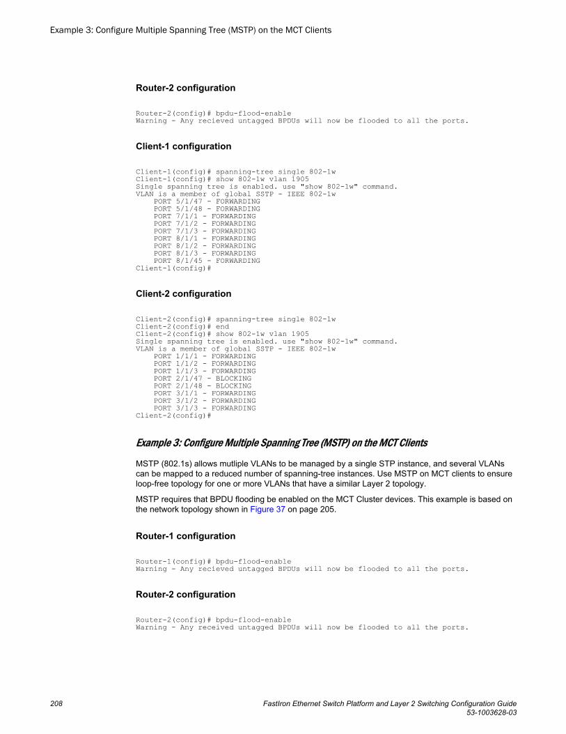
Router-2 configuration
Router-2(config)# bpdu-flood-enableWarning - Any recieved untagged BPDUs will now be flooded to all the ports.
Client-1 configuration
Client-1(config)# spanning-tree single 802-1wClient-1(config)# show 802-1w vlan 1905Single spanning tree is enabled. use "show 802-1w" command.VLAN is a member of global SSTP - IEEE 802-1w PORT 5/1/47 - FORWARDING PORT 5/1/48 - FORWARDING PORT 7/1/1 - FORWARDING PORT 7/1/2 - FORWARDING PORT 7/1/3 - FORWARDING PORT 8/1/1 - FORWARDING PORT 8/1/2 - FORWARDING PORT 8/1/3 - FORWARDING PORT 8/1/45 - FORWARDINGClient-1(config)#
Client-2 configuration
Client-2(config)# spanning-tree single 802-1wClient-2(config)# endClient-2(config)# show 802-1w vlan 1905Single spanning tree is enabled. use "show 802-1w" command.VLAN is a member of global SSTP - IEEE 802-1w PORT 1/1/1 - FORWARDING PORT 1/1/2 - FORWARDING PORT 1/1/3 - FORWARDING PORT 2/1/47 - BLOCKING PORT 2/1/48 - BLOCKING PORT 3/1/1 - FORWARDING PORT 3/1/2 - FORWARDING PORT 3/1/3 - FORWARDINGClient-2(config)#
Example 3: Configure Multiple Spanning Tree (MSTP) on the MCT Clients
MSTP (802.1s) allows mutliple VLANs to be managed by a single STP instance, and several VLANscan be mapped to a reduced number of spanning-tree instances. Use MSTP on MCT clients to ensureloop-free topology for one or more VLANs that have a similar Layer 2 topology.
MSTP requires that BPDU flooding be enabled on the MCT Cluster devices. This example is based onthe network topology shown in Figure 37 on page 205.
Router-1 configuration
Router-1(config)# bpdu-flood-enableWarning - Any recieved untagged BPDUs will now be flooded to all the ports.
Router-2 configuration
Router-2(config)# bpdu-flood-enableWarning - Any received untagged BPDUs will now be flooded to all the ports.
Example 3: Configure Multiple Spanning Tree (MSTP) on the MCT Clients
208 FastIron Ethernet Switch Platform and Layer 2 Switching Configuration Guide53-1003628-03
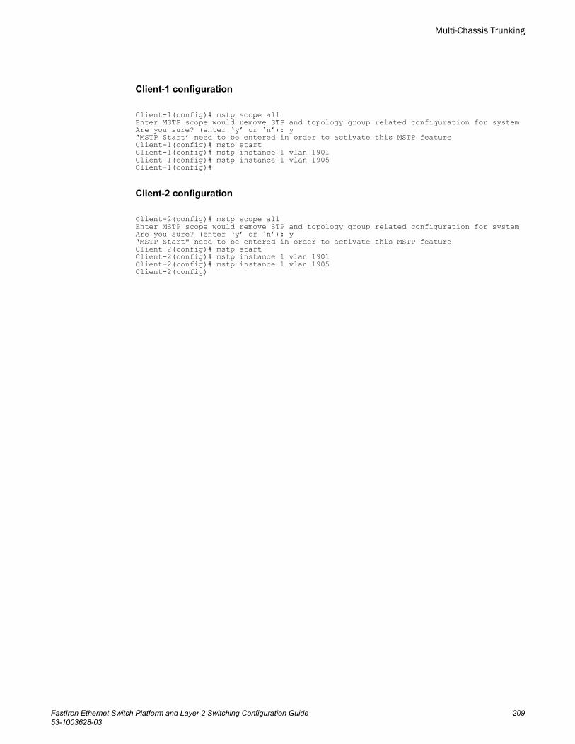
Client-1 configuration
Client-1(config)# mstp scope allEnter MSTP scope would remove STP and topology group related configuration for systemAre you sure? (enter ‘y’ or ‘n’): y‘MSTP Start’ need to be entered in order to activate this MSTP featureClient-1(config)# mstp startClient-1(config)# mstp instance 1 vlan 1901Client-1(config)# mstp instance 1 vlan 1905Client-1(config)#
Client-2 configuration
Client-2(config)# mstp scope allEnter MSTP scope would remove STP and topology group related configuration for systemAre you sure? (enter ‘y’ or ‘n’): y‘MSTP Start" need to be entered in order to activate this MSTP featureClient-2(config)# mstp startClient-2(config)# mstp instance 1 vlan 1901Client-2(config)# mstp instance 1 vlan 1905Client-2(config)
Multi-Chassis Trunking
FastIron Ethernet Switch Platform and Layer 2 Switching Configuration Guide 20953-1003628-03

Example 3: Configure Multiple Spanning Tree (MSTP) on the MCT Clients
210 FastIron Ethernet Switch Platform and Layer 2 Switching Configuration Guide53-1003628-03
GVRP
● GVRP overview.............................................................................................................211● GVRP application examples......................................................................................... 211● VLAN names created by GVRP.................................................................................... 214● Configuration notes for GVRP.......................................................................................214● GVRP configuration...................................................................................................... 215● Converting a VLAN created by GVRP into a statically-configured VLAN..................... 219● Displaying GVRP information........................................................................................220● Clearing GVRP statistics...............................................................................................226● GVRP CLI examples..................................................................................................... 227
GVRP overviewGARP VLAN Registration Protocol (GVRP) is a Generic Attribute Registration Protocol (GARP)application that provides VLAN registration service by means of dynamic configuration (registration) anddistribution of VLAN membership information.
A Brocade device enabled for GVRP can do the following:
• Learn about VLANs from other Brocade devices and configure those VLANs on the ports that learnabout the VLANs. The device listens for GVRP Protocol Data Units (PDUs) from other devices, andimplements the VLAN configuration information in the PDUs.
• Advertise VLANs configured on the device to other Brocade devices. The device sends GVRP PDUsadvertising its VLANs to other devices. GVRP advertises statically configured VLANs and VLANslearned from other devices through GVRP.
GVRP enables a Brocade device to dynamically create 802.1Q-compliant VLANs on links with otherdevices that are running GVRP. GVRP reduces the chances for errors in VLAN configuration byautomatically providing VLAN ID consistency across the network. You can use GVRP to propagateVLANs to other GVRP-aware devices automatically, without the need to manually configure the VLANson each device. In addition, if the VLAN configuration on a device changes, GVRP automaticallychanges the VLAN configurations of the affected devices.
The Brocade implementation of GARP and GVRP is based on the following standards:
• ANSI/IEEE standard 802.1D, 1998 edition• IEEE standard 802.1Q, 1998 edition; approved December 8, 1998• IEEE draft P802.1w/D10, March 26, 2001• IEEE draft P802.1u/D9, November 23, 2000• IEEE draft P802.1t/D10, November 20, 2000
GVRP application examplesThe following figure shows an example of a network that uses GVRP. This section describes variousways you can use GVRP in a network such as this one. GVRP CLI examples on page 227 lists the CLIcommands to implement the applications of GVRP described in this section.
FastIron Ethernet Switch Platform and Layer 2 Switching Configuration Guide 21153-1003628-03
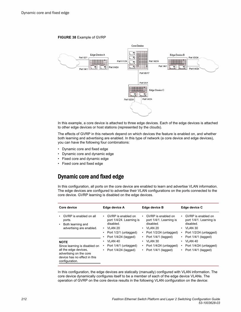
FIGURE 38 Example of GVRP
In this example, a core device is attached to three edge devices. Each of the edge devices is attachedto other edge devices or host stations (represented by the clouds).
The effects of GVRP in this network depend on which devices the feature is enabled on, and whetherboth learning and advertising are enabled. In this type of network (a core device and edge devices),you can have the following four combinations:
• Dynamic core and fixed edge• Dynamic core and dynamic edge• Fixed core and dynamic edge• Fixed core and fixed edge
Dynamic core and fixed edgeIn this configuration, all ports on the core device are enabled to learn and advertise VLAN information.The edge devices are configured to advertise their VLAN configurations on the ports connected to thecore device. GVRP learning is disabled on the edge devices.
Core device Edge device A Edge device B Edge device C
• GVRP is enabled on allports.
• Both learning andadvertising are enabled.
NOTESince learning is disabled onall the edge devices,advertising on the coredevice has no effect in thisconfiguration.
• GVRP is enabled onport 1/4/24. Learning isdisabled.
• VLAN 20• Port 1/2/1 (untagged)• Port 1/4/24 (tagged)• VLAN 40• Port 1/4/1 (untagged)• Port 1/4/24 (tagged)
• GVRP is enabled onport 1/4/1. Learning isdisabled.
• VLAN 20• Port 1/2/24 (untagged)• Port 1/4/1 (tagged)• VLAN 30• Port 1/4/24 (untagged)• Port 1/4/1 (tagged)
• GVRP is enabled onport 1/4/1. Learning isdisabled.
• VLAN 30• Port 1/2/24 (untagged)• Port 1/4/1 (tagged)• VLAN 40• Port 1/4/24 (untagged)• Port 1/4/1 (tagged)
In this configuration, the edge devices are statically (manually) configured with VLAN information. Thecore device dynamically configures itself to be a member of each of the edge device VLANs. Theoperation of GVRP on the core device results in the following VLAN configuration on the device:
Dynamic core and fixed edge
212 FastIron Ethernet Switch Platform and Layer 2 Switching Configuration Guide53-1003628-03
• VLAN 20
‐ 1/1/24 (tagged)‐ 1/6/24 (tagged)
• VLAN 30
‐ 1/6/24 (tagged)‐ 1/8/17 (tagged)
• VLAN 40
‐ 1/1/24 (tagged)‐ 1/8/17 (tagged)
VLAN 20 traffic can now travel through the core between edge devices A and B. Likewise, VLAN 30traffic can travel between B and C and VLAN 40 traffic can travel between A and C. If an edge device ismoved to a different core port or the VLAN configuration of an edge device is changed, the core deviceautomatically reconfigures itself to accommodate the change.
Notice that each of the ports in the dynamically created VLANs is tagged. All GVRP VLAN portsconfigured by GVRP are tagged, to ensure that the port can be configured for additional VLANs.
NOTEThis example assumes that the core device has no static VLANs configured. However, you can havestatic VLANs on a device that is running GVRP. GVRP can dynamically add other ports to the staticallyconfigured VLANs but cannot delete statically configured ports from the VLANs.
Dynamic core and dynamic edgeGVRP is enabled on the core device and on the edge devices. This type of configuration is useful if thedevices in the edge clouds are running GVRP and advertise their VLANs to the edge devices. The edgedevices learn the VLANs and also advertise them to the core. In this configuration, you do not need tostatically configure the VLANs on the edge or core devices, although you can have statically configuredVLANs on the devices. The devices learn the VLANs from the devices in the edge clouds.
Fixed core and dynamic edgeGVRP learning is enabled on the edge devices. The VLANs on the core device are statically configured,and the core device is enabled to advertise its VLANs but not to learn VLANs. The edge devices learnthe VLANs from the core.
Fixed core and fixed edgeThe VLANs are statically configured on the core and edge devices. On each edge device, VLANadvertising is enabled but learning is disabled. GVRP is not enabled on the core device. Thisconfiguration enables the devices in the edge clouds to learn the VLANs configured on the edgedevices.
Dynamic core and dynamic edge
FastIron Ethernet Switch Platform and Layer 2 Switching Configuration Guide 21353-1003628-03
VLAN names created by GVRPThe show vlans command lists VLANs created by GVRP as "GVRP_VLAN_vlan-id ". VLAN namesfor statically configured VLANs are not affected. To distinguish between statically-configured VLANsthat you add to the device and VLANs that you convert from GVRP-configured VLANs into statically-configured VLANs, the show vlans command displays a converted VLAN name as"STATIC_VLAN_vlan-id ".
Configuration notes for GVRP• If you disable GVRP, all GVRP configuration information is lost if you save the configuration change
(write memory command) and then reload the software. However, if you reload the softwarewithout first saving the configuration change, the GVRP configuration is restored following asoftware reload.
• The maximum number of VLANS supported on a device enabled for GVRP is the same as themaximum number on a device that is not enabled for GVRP.
‐ To display the maximum number of VLANs allowed on your device, enter the show defaultvalues command. See the "vlan" row in the System Parameters section. Make sure you allow forthe default VLAN (1), the GVRP base VLAN (4093), and the Single STP VLAN (4094). TheseVLANs are maintained as "Registration Forbidden" in the GVRP database. RegistrationForbidden VLANs cannot be advertised or learned by GVRP.
‐ To increase the maximum number of VLANs supported on the device, enter the system-maxvlannum command at the global CONFIG level of the CLI, then save the configuration andreload the software. The maximum number you can specify is listed in the Maximum column ofthe show default values display.
• The default VLAN (VLAN 1) is not advertised by the Brocade implementation of GVRP. The defaultVLAN contains all ports that are not members of statically configured VLANs or VLANs enabled forGVRP.
NOTEThe default VLAN has ID 1 by default. You can change the VLAN ID of the default VLAN, but onlybefore GVRP is enabled. You cannot change the ID of the default VLAN after GVRP is enabled.
• Single STP must be enabled on the device. Brocade implementation of GVRP requires Single STP.If you do not have any statically configured VLANs on the device, you can enable Single STP asfollows.
device(config)#vlan 1device(config-vlan-1)#exitdevice(config)#spandevice(config)#span singleThese commands enable configuration of the default VLAN (VLAN 1), which contains all the deviceports, and enable STP and Single STP.
• All VLANs that are learned dynamically through GVRP are added to the single spanning tree.• All ports that are enabled for GVRP become tagged members of the GVRP base VLAN (4093). If
you need to use this VLAN ID for another VLAN, you can change the GVRP VLAN ID. Refer to Changing the GVRP base VLAN ID on page 215. The software adds the GVRP base VLAN to thesingle spanning tree.
• All VLAN ports added by GVRP are tagged.
VLAN names created by GVRP
214 FastIron Ethernet Switch Platform and Layer 2 Switching Configuration Guide53-1003628-03
• GVRP is supported only for tagged ports or for untagged ports that are members of the defaultVLAN. GVRP is not supported for ports that are untagged and are members of a VLAN other thanthe default VLAN.
• To configure GVRP on a trunk group, enable the protocol on the primary port in the trunk group. TheGVRP configuration of the primary port is automatically applied to the other ports in the trunk group.
• You can use GVRP on a device even if the device has statically configured VLANs. GVRP does notremove any ports from the statically configured VLANs, although GVRP can add ports to the VLANS.GVRP advertises the statically configured VLANs. Ports added by GVRP do not appear in therunning-config and will not appear in the startup-config file when save the configuration. You canmanually add a port to make the port a permanent member of the VLAN. After you manually add theport, the port will appear in the running-config and be saved to the startup-config file when you savethe configuration.
• VLANs created by GVRP do not support virtual routing interfaces or protocol-based VLANs. virtualrouting interfaces and protocol-based VLANs are still supported on statically configured VLANs evenif GVRP adds ports to those VLANs.
• You cannot manually configure any parameters on a VLAN that is created by GVRP. For example,you cannot change STP parameters for the VLAN.
• The GVRP timers (Join, Leave, and Leaveall) must be set to the same values on all the devices thatare exchanging information using GVRP.
• If the network has a large number of VLANs, the GVRP traffic can use a lot of CPU resources. If younotice high CPU utilization after enabling GVRP, set the GVRP timers to longer values. In particular,set the Leaveall timer to a longer value. Refer to Changing the GVRP timers on page 217.
• The feature is supported only on Ethernet ports.
NOTEIf you plan to change the GVRP base VLAN ID (4093) or the maximum configurable value for theLeaveall timer (300000 ms by default), you must do so before you enable GVRP.
GVRP configurationTo configure a device for GVRP, globally enable support for the feature, then enable the feature onspecific ports. Optionally, you can disable VLAN learning or advertising on specific interfaces.
You can also change the protocol timers and the GVRP base VLAN ID.
Changing the GVRP base VLAN IDBy default, GVRP uses VLAN 4093 as a base VLAN for the protocol. All ports that are enabled forGVRP become tagged members of this VLAN. If you need to use VLAN ID 4093 for a staticallyconfigured VLAN, you can change the GVRP base VLAN ID.
NOTEIf you want to change the GVRP base VLAN ID, you must do so before enabling GVRP.
To change the GVRP base VLAN ID, enter a command such as the following at the global CONFIGlevel of the CLI.
device(config)#gvrp-base-vlan-id 1001This command changes the GVRP VLAN ID from 4093 to 1001.
GVRP configuration
FastIron Ethernet Switch Platform and Layer 2 Switching Configuration Guide 21553-1003628-03
Syntax: [no] gvrp-base-vlan-id vlan-id
The vlan-id parameter specifies the new VLAN ID. You can specify a VLAN ID from 2 - 4092 or 4095.
Increasing the maximum configurable value of the Leaveall timerBy default, the highest value you can specify for the Leaveall timer is 300000 ms. You can increasethe maximum configurable value of the Leaveall timer to 1000000 ms.
NOTEYou must enter this command before enabling GVRP. Once GVRP is enabled, you cannot change themaximum Leaveall timer value.
NOTEThis command does not change the default value of the Leaveall timer itself. The command onlychanges the maximum value to which you can set the Leaveall timer.
To increase the maximum value you can specify for the Leaveall timer, enter a command such as thefollowing at the global CONFIG level of the CLI.
device(config)#gvrp-max-leaveall-timer 1000000Syntax: [no] gvrp-max-leaveall-timer ms
The ms parameter specifies the maximum number of ms to which you can set the Leaveall timer. Youcan specify from 300000 - 1000000 (one million) ms. The value must be a multiple of 100 ms. Thedefault is 300000 ms.
Enabling GVRPTo enable GVRP, enter commands such as the following at the global CONFIG level of the CLI.
device(config)# gvrp-enabledevice(config-gvrp)# enable allThe first command globally enables support for the feature and changes the CLI to the GVRPconfiguration level. The second command enables GVRP on all ports on the device.
The following command enables GVRP on ports 1/1/24, 1/2/24, and 1/4/17.
device(config-gvrp)# enable ethernet 1/1/24 ethernet 1/2/24 ethernet 1/4/17Syntax: [no] gvrp-enable
Syntax: [no] enable all | ethernet stackid/slot/port [ethernet stackid/slot/port | to stackid/slot/port]
The all keyword enables GVRP on all ports.
To specify a list of ports, enter each port as ethernet stackid/slot/port followed by a space. Forexample, ethernet 1/1/24 ethernet 1/6/24 ethernet 1/8/17
To specify a range of ports, enter the first port in the range as ethernet stackid/slot/port followed bythe last port in the range. For example, ethernet 1/1/1 to 1/1/8 .
You can combine lists and ranges in the same command. For example: enable ethernet 1/1/1 to1/1/8 ethernet 1/1/24 ethernet 1/6/24 ethernet 1/8/17.
Increasing the maximum configurable value of the Leaveall timer
216 FastIron Ethernet Switch Platform and Layer 2 Switching Configuration Guide53-1003628-03
Disabling VLAN advertisingTo disable VLAN advertising on a port enabled for GVRP, enter a command such as the following at theGVRP configuration level.
device(config-gvrp)# block-applicant ethernet 1/1/24 ethernet 1/6/24 ethernet 1/8/17This command disables advertising of VLAN information on ports 1/1/24, 1/6/24, and 1/8/17.
Syntax: [no] block-applicant all | ethernet stackid/slot/port [ethernet stackid/slot/port | to stackid/slot/port]
NOTELeaveall messages are still sent on the GVRP ports.
The all keyword disables VLAN advertising on all ports enabled for GVRP.
To specify a list of ports, enter each port as ethernet stackid/slot/port followed by a space. Forexample, ethernet 1/1/24 ethernet 1/6/24 ethernet 1/8/17
To specify a range of ports, enter the first port in the range as ethernet stackid/slot/port followed by thelast port in the range. For example, ethernet 1/1/1 to 1/1/8 .
You can combine lists and ranges in the same command. For example: enable ethernet 1/1/1 to 1/1/8ethernet 1/1/24 ethernet 1/6/24 ethernet 1/8/17.
Disabling VLAN learningTo disable VLAN learning on a port enabled for GVRP, enter a command such as the following at theGVRP configuration level.
device(config-gvrp)# block-learning ethernet 1/6/24This command disables learning of VLAN information on port 1/6/24.
NOTEThe port still advertises VLAN information unless you also disable VLAN advertising.
Syntax: [no] block-learning all | ethernet stackid/slot/port [ethernet stackid/slot/port | to stackid/slot/port]
The all keyword disables VLAN learning on all ports enabled for GVRP.
To specify a list of ports, enter each port as ethernet stackid/slot/port followed by a space. Forexample, ethernet 1/1/24 ethernet 1/6/24 ethernet 1/8/17
To specify a range of ports, enter the first port in the range as ethernet stackid/slot/port followed by thelast port in the range. For example, ethernet 1/1/1 to 1/1/8 .
You can combine lists and ranges in the same command. For example: enable ethernet 1/1/1 to 1/1/8ethernet 1/1/24 ethernet 1/6/24 ethernet 1/8/17.
Changing the GVRP timersGVRP uses the following timers:
Disabling VLAN advertising
FastIron Ethernet Switch Platform and Layer 2 Switching Configuration Guide 21753-1003628-03
• Join - The maximum number of milliseconds (ms) a device GVRP interfaces wait before sendingVLAN advertisements on the interfaces. The actual interval between Join messages is randomlycalculated to a value between 0 and the maximum number of milliseconds specified for Joinmessages. You can set the Join timer to a value from 200 - one third the value of the Leave timer.The default is 200 ms.
• Leave - The number of ms a GVRP interface waits after receiving a Leave message on the port toremove the port from the VLAN indicated in the Leave message. If the port receives a Joinmessage before the Leave timer expires, GVRP keeps the port in the VLAN. Otherwise, the port isremoved from the VLAN. When a port receives a Leave message, the port GVRP state is changedto Leaving. Once the Leave timer expires, the port GVRP state changes to Empty. You can set theLeave timer to a value from three times the Join timer - one fifth the value of the Leaveall timer. Thedefault is 600 ms.
NOTEWhen all ports in a dynamically created VLAN (one learned through GVRP) leave the VLAN, theVLAN is immediately deleted from the device's VLAN database. However, this empty VLAN is stillmaintained in the GVRP database for an amount of time equal to the following. (number-of-GVRP-enabled-up-ports) * (2 * join-timer)While the empty VLAN is in the GVRP database, the VLAN doesnot appear in the show vlans display but does still appear in the show gvrp vlan all display.
• Leaveall - The minimum interval at which GVRP sends Leaveall messages on all GVRP interfaces.Leaveall messages ensure that the GVRP VLAN membership information is current by aging outstale VLAN information and adding information for new VLAN memberships, if the information ismissing. A Leaveall message instructs the port to change the GVRP state for all its VLANs toLeaving, and remove them unless a Join message is received before the Leave timer expires. Bydefault, you can set the Leaveall timer to a value from five times the Leave timer - maximum valueallowed by software (configurable from 300000 - 1000000 ms). The default is 10000.
NOTEThe actual interval is a random value between the Leaveall interval and 1.5 * the Leaveall time orthe maximum Leaveall time, whichever is lower.
NOTEYou can increase the maximum configurable value of the Leaveall timer from 300000 ms up to1000000 ms using the gvrp-max-leaveall-timer command. (Refer to Increasing the maximumconfigurable value of the Leaveall timer on page 216.)
Timer configuration requirements
• All timer values must be in multiples of 100 ms.• The Leave timer must be >= 3* the Join timer.• The Leaveall timer must be >= 5* the Leave timer.• The GVRP timers must be set to the same values on all the devices that are exchanging
information using GVRP.
Changing the Join, Leave, and Leaveall timers
The same CLI command controls changes to the Join, Leave, and Leaveall timers. To change valuesto the timers, enter a command such as the following.
device(config-gvrp)#join-timer 1000 leave-timer 3000 leaveall-timer 15000
Timer configuration requirements
218 FastIron Ethernet Switch Platform and Layer 2 Switching Configuration Guide53-1003628-03
This command changes the Join timer to 1000 ms, the Leave timer to 3000 ms, and the Leaveall timerto 15000.
Syntax: [no] join-timer ms leave-timer ms leaveall-timer ms
NOTEWhen you enter this command, all the running GVRP timers are canceled and restarted using the newtimes specified by the command.
Resetting the timers to their defaults
To reset the Join, Leave, and Leaveall timers to their default values, enter the following command.
device(config-gvrp)#default-timersSyntax: default-timers
This command resets the timers to the following values:
• Join - 200 ms• Leave - 600 ms• Leaveall - 10000 ms
Converting a VLAN created by GVRP into a statically-configured VLAN
You cannot configure VLAN parameters on VLANs created by GVRP. Moreover, VLANs and VLANports added by GVRP do not appear in the running-config and cannot be saved in the startup-config file.
To be able to configure and save VLANs or ports added by GVRP, you must convert the VLAN ports tostatically-configured ports.
To convert a VLAN added by GVRP into a statically-configured VLAN, add the ports using commandssuch as the following.
device(config)#vlan 22device(config-vlan-222)#tagged ethernet 1/1/1 to 1/1/8These commands convert GVRP-created VLAN 22 containing ports 1/1/1 through 1/1/8 into statically-configured VLAN 22.
Syntax: [no] vlan vlan-id
Syntax: [no] tagged ethernet stackid/slot/port [to stackid/slot/port | ethernet stackid/slot/port]
Use the same commands to statically add ports that GVRP added to a VLAN.
NOTEYou cannot add the VLAN ports as untagged ports.
NOTEAfter you convert the VLAN, the VLAN name changes from "‘GVRP_VLAN_vlan-id " to"STATIC_VLAN_vlan-id ".
Resetting the timers to their defaults
FastIron Ethernet Switch Platform and Layer 2 Switching Configuration Guide 21953-1003628-03
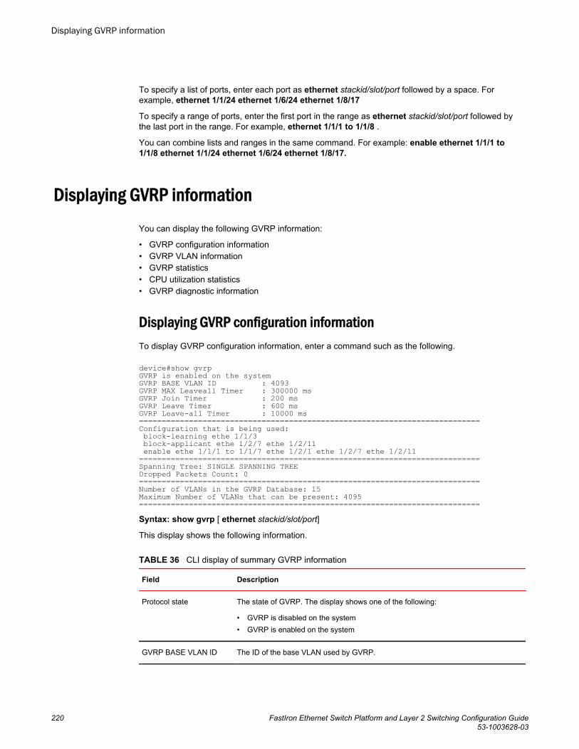
To specify a list of ports, enter each port as ethernet stackid/slot/port followed by a space. Forexample, ethernet 1/1/24 ethernet 1/6/24 ethernet 1/8/17
To specify a range of ports, enter the first port in the range as ethernet stackid/slot/port followed bythe last port in the range. For example, ethernet 1/1/1 to 1/1/8 .
You can combine lists and ranges in the same command. For example: enable ethernet 1/1/1 to1/1/8 ethernet 1/1/24 ethernet 1/6/24 ethernet 1/8/17.
Displaying GVRP informationYou can display the following GVRP information:
• GVRP configuration information• GVRP VLAN information• GVRP statistics• CPU utilization statistics• GVRP diagnostic information
Displaying GVRP configuration informationTo display GVRP configuration information, enter a command such as the following.
device#show gvrpGVRP is enabled on the systemGVRP BASE VLAN ID : 4093GVRP MAX Leaveall Timer : 300000 msGVRP Join Timer : 200 msGVRP Leave Timer : 600 msGVRP Leave-all Timer : 10000 ms===========================================================================Configuration that is being used: block-learning ethe 1/1/3 block-applicant ethe 1/2/7 ethe 1/2/11 enable ethe 1/1/1 to 1/1/7 ethe 1/2/1 ethe 1/2/7 ethe 1/2/11===========================================================================Spanning Tree: SINGLE SPANNING TREEDropped Packets Count: 0===========================================================================Number of VLANs in the GVRP Database: 15Maximum Number of VLANs that can be present: 4095===========================================================================Syntax: show gvrp [ ethernet stackid/slot/port]
This display shows the following information.
CLI display of summary GVRP information TABLE 36
Field Description
Protocol state The state of GVRP. The display shows one of the following:
• GVRP is disabled on the system• GVRP is enabled on the system
GVRP BASE VLAN ID The ID of the base VLAN used by GVRP.
Displaying GVRP information
220 FastIron Ethernet Switch Platform and Layer 2 Switching Configuration Guide53-1003628-03
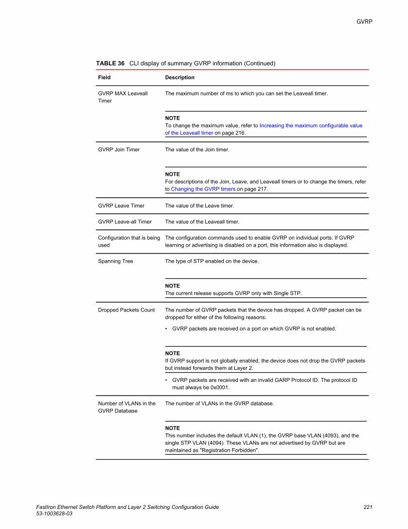
CLI display of summary GVRP information (Continued)TABLE 36
Field Description
GVRP MAX LeaveallTimer
The maximum number of ms to which you can set the Leaveall timer.
NOTETo change the maximum value, refer to Increasing the maximum configurable valueof the Leaveall timer on page 216.
GVRP Join Timer The value of the Join timer.
NOTEFor descriptions of the Join, Leave, and Leaveall timers or to change the timers, referto Changing the GVRP timers on page 217.
GVRP Leave Timer The value of the Leave timer.
GVRP Leave-all Timer The value of the Leaveall timer.
Configuration that is beingused
The configuration commands used to enable GVRP on individual ports. If GVRPlearning or advertising is disabled on a port, this information also is displayed.
Spanning Tree The type of STP enabled on the device.
NOTEThe current release supports GVRP only with Single STP.
Dropped Packets Count The number of GVRP packets that the device has dropped. A GVRP packet can bedropped for either of the following reasons:
• GVRP packets are received on a port on which GVRP is not enabled.
NOTEIf GVRP support is not globally enabled, the device does not drop the GVRP packetsbut instead forwards them at Layer 2.
• GVRP packets are received with an invalid GARP Protocol ID. The protocol IDmust always be 0x0001.
Number of VLANs in theGVRP Database
The number of VLANs in the GVRP database.
NOTEThis number includes the default VLAN (1), the GVRP base VLAN (4093), and thesingle STP VLAN (4094). These VLANs are not advertised by GVRP but aremaintained as "Registration Forbidden".
GVRP
FastIron Ethernet Switch Platform and Layer 2 Switching Configuration Guide 22153-1003628-03
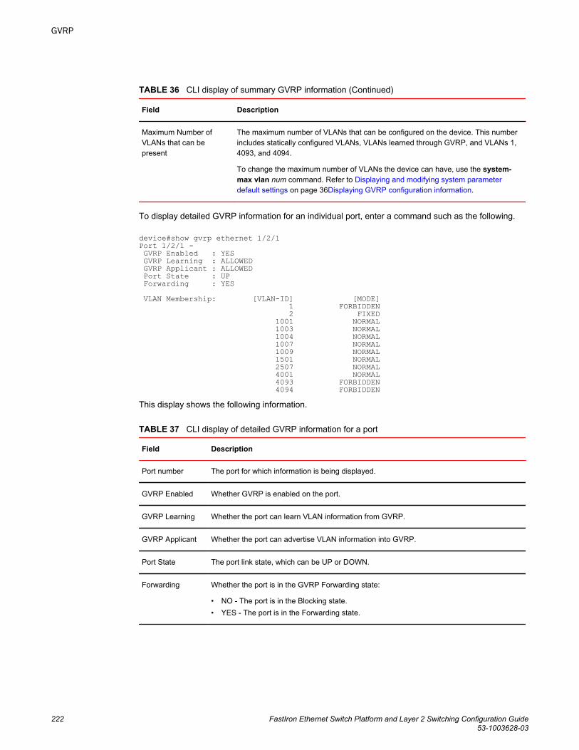
CLI display of summary GVRP information (Continued)TABLE 36
Field Description
Maximum Number ofVLANs that can bepresent
The maximum number of VLANs that can be configured on the device. This numberincludes statically configured VLANs, VLANs learned through GVRP, and VLANs 1,4093, and 4094.
To change the maximum number of VLANs the device can have, use the system-max vlan num command. Refer to Displaying and modifying system parameterdefault settings on page 36Displaying GVRP configuration information.
To display detailed GVRP information for an individual port, enter a command such as the following.
device#show gvrp ethernet 1/2/1Port 1/2/1 - GVRP Enabled : YES GVRP Learning : ALLOWED GVRP Applicant : ALLOWED Port State : UP Forwarding : YES VLAN Membership: [VLAN-ID] [MODE] 1 FORBIDDEN 2 FIXED 1001 NORMAL 1003 NORMAL 1004 NORMAL 1007 NORMAL 1009 NORMAL 1501 NORMAL 2507 NORMAL 4001 NORMAL 4093 FORBIDDEN 4094 FORBIDDENThis display shows the following information.
CLI display of detailed GVRP information for a port TABLE 37
Field Description
Port number The port for which information is being displayed.
GVRP Enabled Whether GVRP is enabled on the port.
GVRP Learning Whether the port can learn VLAN information from GVRP.
GVRP Applicant Whether the port can advertise VLAN information into GVRP.
Port State The port link state, which can be UP or DOWN.
Forwarding Whether the port is in the GVRP Forwarding state:
• NO - The port is in the Blocking state.• YES - The port is in the Forwarding state.
GVRP
222 FastIron Ethernet Switch Platform and Layer 2 Switching Configuration Guide53-1003628-03
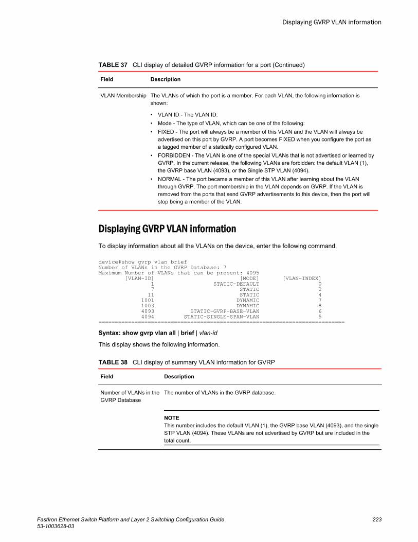
CLI display of detailed GVRP information for a port (Continued)TABLE 37
Field Description
VLAN Membership The VLANs of which the port is a member. For each VLAN, the following information isshown:
• VLAN ID - The VLAN ID.• Mode - The type of VLAN, which can be one of the following:• FIXED - The port will always be a member of this VLAN and the VLAN will always be
advertised on this port by GVRP. A port becomes FIXED when you configure the port asa tagged member of a statically configured VLAN.
• FORBIDDEN - The VLAN is one of the special VLANs that is not advertised or learned byGVRP. In the current release, the following VLANs are forbidden: the default VLAN (1),the GVRP base VLAN (4093), or the Single STP VLAN (4094).
• NORMAL - The port became a member of this VLAN after learning about the VLANthrough GVRP. The port membership in the VLAN depends on GVRP. If the VLAN isremoved from the ports that send GVRP advertisements to this device, then the port willstop being a member of the VLAN.
Displaying GVRP VLAN informationTo display information about all the VLANs on the device, enter the following command.
device#show gvrp vlan briefNumber of VLANs in the GVRP Database: 7Maximum Number of VLANs that can be present: 4095 [VLAN-ID] [MODE] [VLAN-INDEX] 1 STATIC-DEFAULT 0 7 STATIC 2 11 STATIC 4 1001 DYNAMIC 7 1003 DYNAMIC 8 4093 STATIC-GVRP-BASE-VLAN 6 4094 STATIC-SINGLE-SPAN-VLAN 5===========================================================================Syntax: show gvrp vlan all | brief | vlan-id
This display shows the following information.
CLI display of summary VLAN information for GVRP TABLE 38
Field Description
Number of VLANs in theGVRP Database
The number of VLANs in the GVRP database.
NOTEThis number includes the default VLAN (1), the GVRP base VLAN (4093), and the singleSTP VLAN (4094). These VLANs are not advertised by GVRP but are included in thetotal count.
Displaying GVRP VLAN information
FastIron Ethernet Switch Platform and Layer 2 Switching Configuration Guide 22353-1003628-03
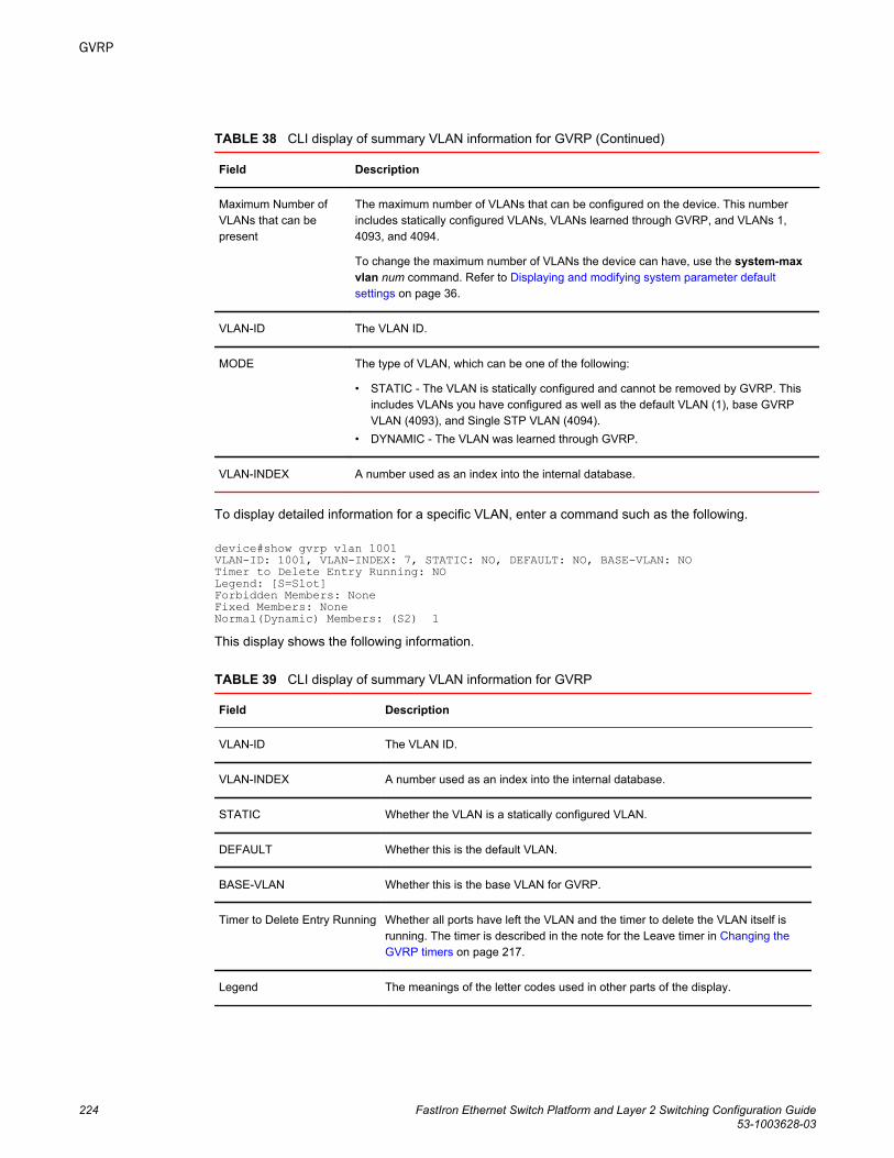
CLI display of summary VLAN information for GVRP (Continued)TABLE 38
Field Description
Maximum Number ofVLANs that can bepresent
The maximum number of VLANs that can be configured on the device. This numberincludes statically configured VLANs, VLANs learned through GVRP, and VLANs 1,4093, and 4094.
To change the maximum number of VLANs the device can have, use the system-maxvlan num command. Refer to Displaying and modifying system parameter defaultsettings on page 36.
VLAN-ID The VLAN ID.
MODE The type of VLAN, which can be one of the following:
• STATIC - The VLAN is statically configured and cannot be removed by GVRP. Thisincludes VLANs you have configured as well as the default VLAN (1), base GVRPVLAN (4093), and Single STP VLAN (4094).
• DYNAMIC - The VLAN was learned through GVRP.
VLAN-INDEX A number used as an index into the internal database.
To display detailed information for a specific VLAN, enter a command such as the following.
device#show gvrp vlan 1001VLAN-ID: 1001, VLAN-INDEX: 7, STATIC: NO, DEFAULT: NO, BASE-VLAN: NOTimer to Delete Entry Running: NOLegend: [S=Slot]Forbidden Members: NoneFixed Members: NoneNormal(Dynamic) Members: (S2) 1This display shows the following information.
CLI display of summary VLAN information for GVRP TABLE 39
Field Description
VLAN-ID The VLAN ID.
VLAN-INDEX A number used as an index into the internal database.
STATIC Whether the VLAN is a statically configured VLAN.
DEFAULT Whether this is the default VLAN.
BASE-VLAN Whether this is the base VLAN for GVRP.
Timer to Delete Entry Running Whether all ports have left the VLAN and the timer to delete the VLAN itself isrunning. The timer is described in the note for the Leave timer in Changing theGVRP timers on page 217.
Legend The meanings of the letter codes used in other parts of the display.
GVRP
224 FastIron Ethernet Switch Platform and Layer 2 Switching Configuration Guide53-1003628-03
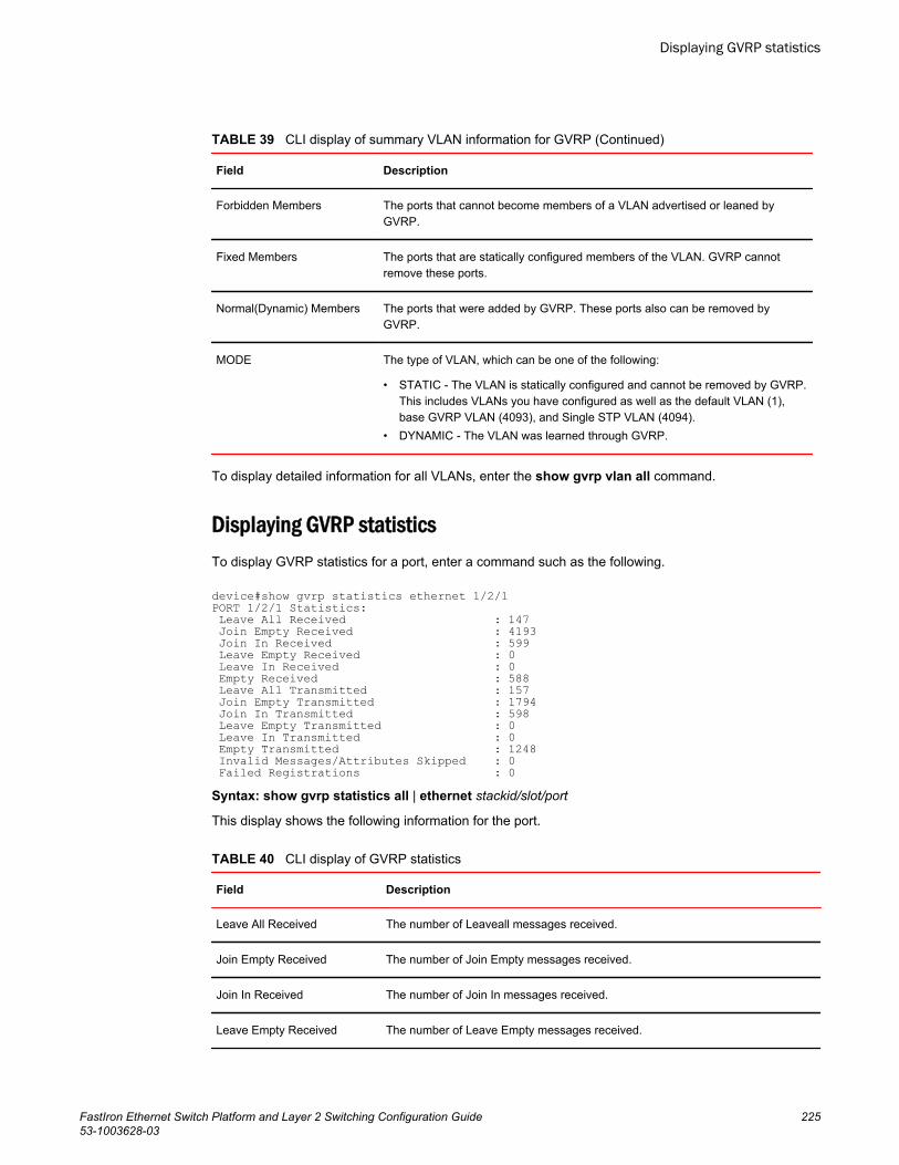
CLI display of summary VLAN information for GVRP (Continued)TABLE 39
Field Description
Forbidden Members The ports that cannot become members of a VLAN advertised or leaned byGVRP.
Fixed Members The ports that are statically configured members of the VLAN. GVRP cannotremove these ports.
Normal(Dynamic) Members The ports that were added by GVRP. These ports also can be removed byGVRP.
MODE The type of VLAN, which can be one of the following:
• STATIC - The VLAN is statically configured and cannot be removed by GVRP.This includes VLANs you have configured as well as the default VLAN (1),base GVRP VLAN (4093), and Single STP VLAN (4094).
• DYNAMIC - The VLAN was learned through GVRP.
To display detailed information for all VLANs, enter the show gvrp vlan all command.
Displaying GVRP statisticsTo display GVRP statistics for a port, enter a command such as the following.
device#show gvrp statistics ethernet 1/2/1PORT 1/2/1 Statistics: Leave All Received : 147 Join Empty Received : 4193 Join In Received : 599 Leave Empty Received : 0 Leave In Received : 0 Empty Received : 588 Leave All Transmitted : 157 Join Empty Transmitted : 1794 Join In Transmitted : 598 Leave Empty Transmitted : 0 Leave In Transmitted : 0 Empty Transmitted : 1248 Invalid Messages/Attributes Skipped : 0 Failed Registrations : 0 Syntax: show gvrp statistics all | ethernet stackid/slot/port
This display shows the following information for the port.
CLI display of GVRP statistics TABLE 40
Field Description
Leave All Received The number of Leaveall messages received.
Join Empty Received The number of Join Empty messages received.
Join In Received The number of Join In messages received.
Leave Empty Received The number of Leave Empty messages received.
Displaying GVRP statistics
FastIron Ethernet Switch Platform and Layer 2 Switching Configuration Guide 22553-1003628-03
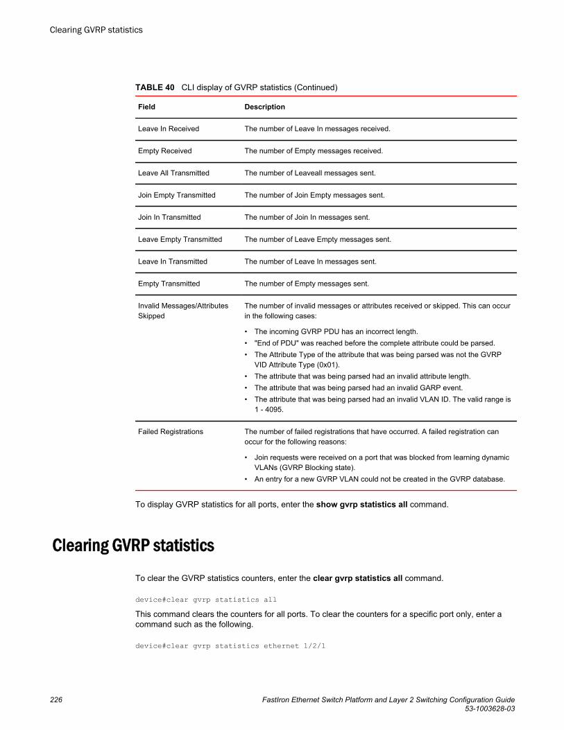
CLI display of GVRP statistics (Continued)TABLE 40
Field Description
Leave In Received The number of Leave In messages received.
Empty Received The number of Empty messages received.
Leave All Transmitted The number of Leaveall messages sent.
Join Empty Transmitted The number of Join Empty messages sent.
Join In Transmitted The number of Join In messages sent.
Leave Empty Transmitted The number of Leave Empty messages sent.
Leave In Transmitted The number of Leave In messages sent.
Empty Transmitted The number of Empty messages sent.
Invalid Messages/AttributesSkipped
The number of invalid messages or attributes received or skipped. This can occurin the following cases:
• The incoming GVRP PDU has an incorrect length.• "End of PDU" was reached before the complete attribute could be parsed.• The Attribute Type of the attribute that was being parsed was not the GVRP
VID Attribute Type (0x01).• The attribute that was being parsed had an invalid attribute length.• The attribute that was being parsed had an invalid GARP event.• The attribute that was being parsed had an invalid VLAN ID. The valid range is
1 - 4095.
Failed Registrations The number of failed registrations that have occurred. A failed registration canoccur for the following reasons:
• Join requests were received on a port that was blocked from learning dynamicVLANs (GVRP Blocking state).
• An entry for a new GVRP VLAN could not be created in the GVRP database.
To display GVRP statistics for all ports, enter the show gvrp statistics all command.
Clearing GVRP statistics
To clear the GVRP statistics counters, enter the clear gvrp statistics all command.
device#clear gvrp statistics allThis command clears the counters for all ports. To clear the counters for a specific port only, enter acommand such as the following.
device#clear gvrp statistics ethernet 1/2/1
Clearing GVRP statistics
226 FastIron Ethernet Switch Platform and Layer 2 Switching Configuration Guide53-1003628-03
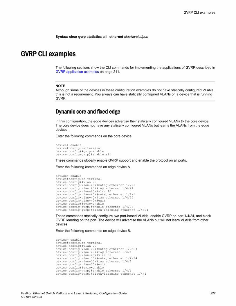
Syntax: clear gvrp statistics all | ethernet stackid/slot/port
GVRP CLI examplesThe following sections show the CLI commands for implementing the applications of GVRP described in GVRP application examples on page 211.
NOTEAlthough some of the devices in these configuration examples do not have statically configured VLANs,this is not a requirement. You always can have statically configured VLANs on a device that is runningGVRP.
Dynamic core and fixed edgeIn this configuration, the edge devices advertise their statically configured VLANs to the core device.The core device does not have any statically configured VLANs but learns the VLANs from the edgedevices.
Enter the following commands on the core device.
device> enabledevice#configure terminaldevice(config)#gvrp-enabledevice(config-gvrp)#enable allThese commands globally enable GVRP support and enable the protocol on all ports.
Enter the following commands on edge device A.
device> enabledevice#configure terminaldevice(config)#vlan 20 device(config-vlan-20)#untag ethernet 1/2/1 device(config-vlan-20)#tag ethernet 1/4/24 device(config-vlan-20)#vlan 40 device(config-vlan-40)#untag ethernet 1/2/1 device(config-vlan-40)#tag ethernet 1/4/24 device(config-vlan-40)#exitdevice(config)#gvrp-enabledevice(config-gvrp)#enable ethernet 1/4/24device(config-gvrp)#block-learning ethernet 1/4/24These commands statically configure two port-based VLANs, enable GVRP on port 1/4/24, and blockGVRP learning on the port. The device will advertise the VLANs but will not learn VLANs from otherdevices.
Enter the following commands on edge device B.
device> enabledevice#configure terminaldevice(config)#vlan 20 device(config-vlan-20)#untag ethernet 1/2/24 device(config-vlan-20)#tag ethernet 1/4/1 device(config-vlan-20)#vlan 30 device(config-vlan-30)#untag ethernet 1/4/24 device(config-vlan-30)#tag ethernet 1/4/1 device(config-vlan-30)#exitdevice(config)#gvrp-enabledevice(config-gvrp)#enable ethernet 1/4/1device(config-gvrp)#block-learning ethernet 1/4/1
GVRP CLI examples
FastIron Ethernet Switch Platform and Layer 2 Switching Configuration Guide 22753-1003628-03
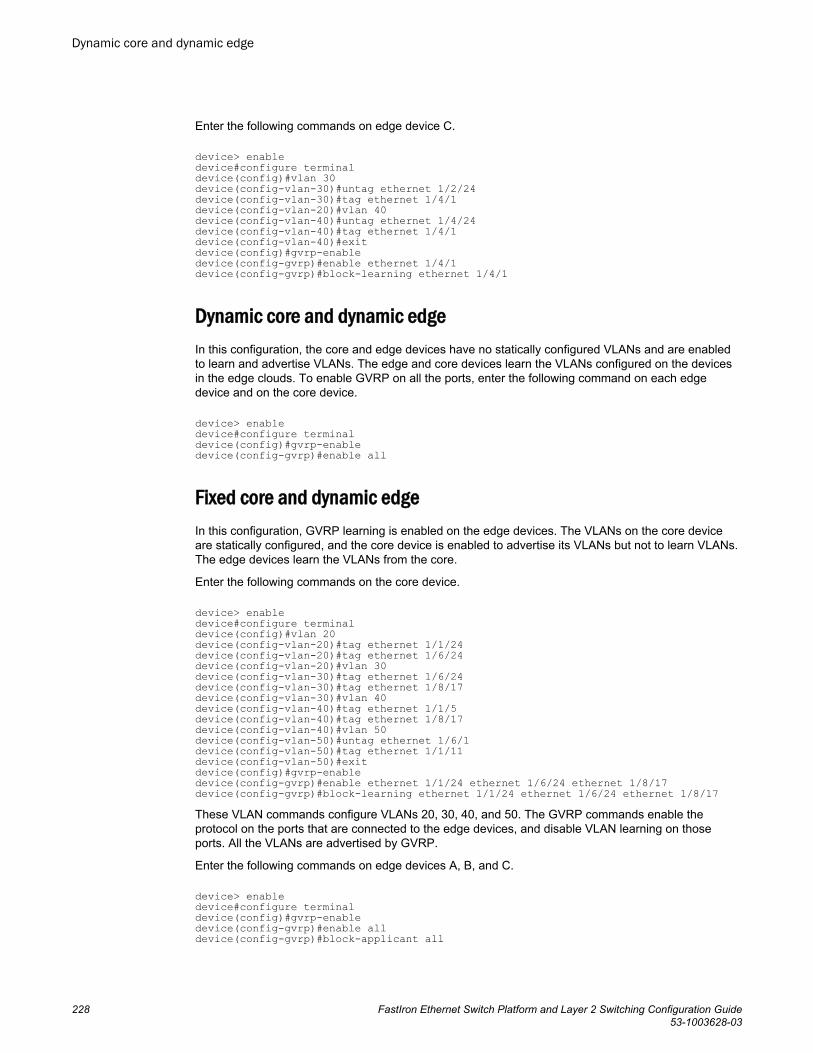
Enter the following commands on edge device C.
device> enabledevice#configure terminaldevice(config)#vlan 30 device(config-vlan-30)#untag ethernet 1/2/24 device(config-vlan-30)#tag ethernet 1/4/1 device(config-vlan-20)#vlan 40 device(config-vlan-40)#untag ethernet 1/4/24 device(config-vlan-40)#tag ethernet 1/4/1 device(config-vlan-40)#exitdevice(config)#gvrp-enabledevice(config-gvrp)#enable ethernet 1/4/1device(config-gvrp)#block-learning ethernet 1/4/1
Dynamic core and dynamic edgeIn this configuration, the core and edge devices have no statically configured VLANs and are enabledto learn and advertise VLANs. The edge and core devices learn the VLANs configured on the devicesin the edge clouds. To enable GVRP on all the ports, enter the following command on each edgedevice and on the core device.
device> enabledevice#configure terminaldevice(config)#gvrp-enabledevice(config-gvrp)#enable all
Fixed core and dynamic edgeIn this configuration, GVRP learning is enabled on the edge devices. The VLANs on the core deviceare statically configured, and the core device is enabled to advertise its VLANs but not to learn VLANs.The edge devices learn the VLANs from the core.
Enter the following commands on the core device.
device> enabledevice#configure terminaldevice(config)#vlan 20 device(config-vlan-20)#tag ethernet 1/1/24 device(config-vlan-20)#tag ethernet 1/6/24 device(config-vlan-20)#vlan 30 device(config-vlan-30)#tag ethernet 1/6/24 device(config-vlan-30)#tag ethernet 1/8/17 device(config-vlan-30)#vlan 40device(config-vlan-40)#tag ethernet 1/1/5 device(config-vlan-40)#tag ethernet 1/8/17 device(config-vlan-40)#vlan 50device(config-vlan-50)#untag ethernet 1/6/1 device(config-vlan-50)#tag ethernet 1/1/11 device(config-vlan-50)#exitdevice(config)#gvrp-enabledevice(config-gvrp)#enable ethernet 1/1/24 ethernet 1/6/24 ethernet 1/8/17device(config-gvrp)#block-learning ethernet 1/1/24 ethernet 1/6/24 ethernet 1/8/17These VLAN commands configure VLANs 20, 30, 40, and 50. The GVRP commands enable theprotocol on the ports that are connected to the edge devices, and disable VLAN learning on thoseports. All the VLANs are advertised by GVRP.
Enter the following commands on edge devices A, B, and C.
device> enabledevice#configure terminaldevice(config)#gvrp-enabledevice(config-gvrp)#enable alldevice(config-gvrp)#block-applicant all
Dynamic core and dynamic edge
228 FastIron Ethernet Switch Platform and Layer 2 Switching Configuration Guide53-1003628-03

Fixed core and fixed edgeThe VLANs are statically configured on the core and edge devices. On each edge device, VLANadvertising is enabled but learning is disabled. GVRP is not configured on the core device. Thisconfiguration enables the devices in the edge clouds to learn the VLANs configured on the edgedevices.
This configuration does not use any GVRP configuration on the core device.
The configuration on the edge device is the same as in Dynamic core and fixed edge on page 227.
Fixed core and fixed edge
FastIron Ethernet Switch Platform and Layer 2 Switching Configuration Guide 22953-1003628-03

Fixed core and fixed edge
230 FastIron Ethernet Switch Platform and Layer 2 Switching Configuration Guide53-1003628-03
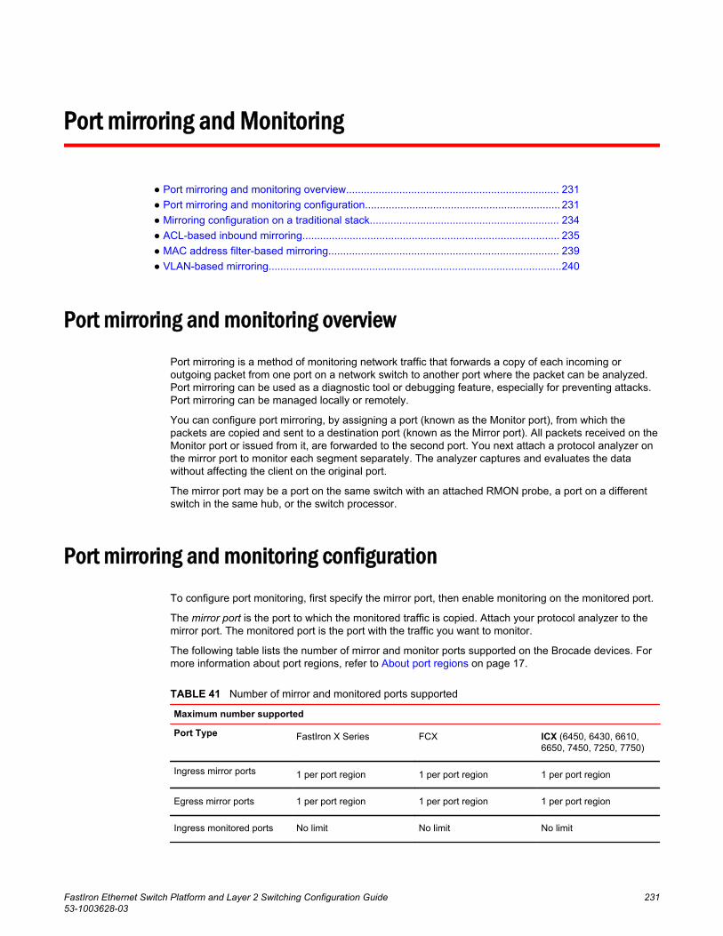
Port mirroring and Monitoring
● Port mirroring and monitoring overview........................................................................ 231● Port mirroring and monitoring configuration.................................................................. 231● Mirroring configuration on a traditional stack................................................................ 234● ACL-based inbound mirroring....................................................................................... 235● MAC address filter-based mirroring.............................................................................. 239● VLAN-based mirroring...................................................................................................240
Port mirroring and monitoring overviewPort mirroring is a method of monitoring network traffic that forwards a copy of each incoming oroutgoing packet from one port on a network switch to another port where the packet can be analyzed.Port mirroring can be used as a diagnostic tool or debugging feature, especially for preventing attacks.Port mirroring can be managed locally or remotely.
You can configure port mirroring, by assigning a port (known as the Monitor port), from which thepackets are copied and sent to a destination port (known as the Mirror port). All packets received on theMonitor port or issued from it, are forwarded to the second port. You next attach a protocol analyzer onthe mirror port to monitor each segment separately. The analyzer captures and evaluates the datawithout affecting the client on the original port.
The mirror port may be a port on the same switch with an attached RMON probe, a port on a differentswitch in the same hub, or the switch processor.
Port mirroring and monitoring configurationTo configure port monitoring, first specify the mirror port, then enable monitoring on the monitored port.
The mirror port is the port to which the monitored traffic is copied. Attach your protocol analyzer to themirror port. The monitored port is the port with the traffic you want to monitor.
The following table lists the number of mirror and monitor ports supported on the Brocade devices. Formore information about port regions, refer to About port regions on page 17.
Number of mirror and monitored ports supportedTABLE 41
Maximum number supported
Port Type FastIron X Series FCX ICX (6450, 6430, 6610,6650, 7450, 7250, 7750)
Ingress mirror ports 1 per port region 1 per port region 1 per port region
Egress mirror ports 1 per port region 1 per port region 1 per port region
Ingress monitored ports No limit No limit No limit
FastIron Ethernet Switch Platform and Layer 2 Switching Configuration Guide 23153-1003628-03
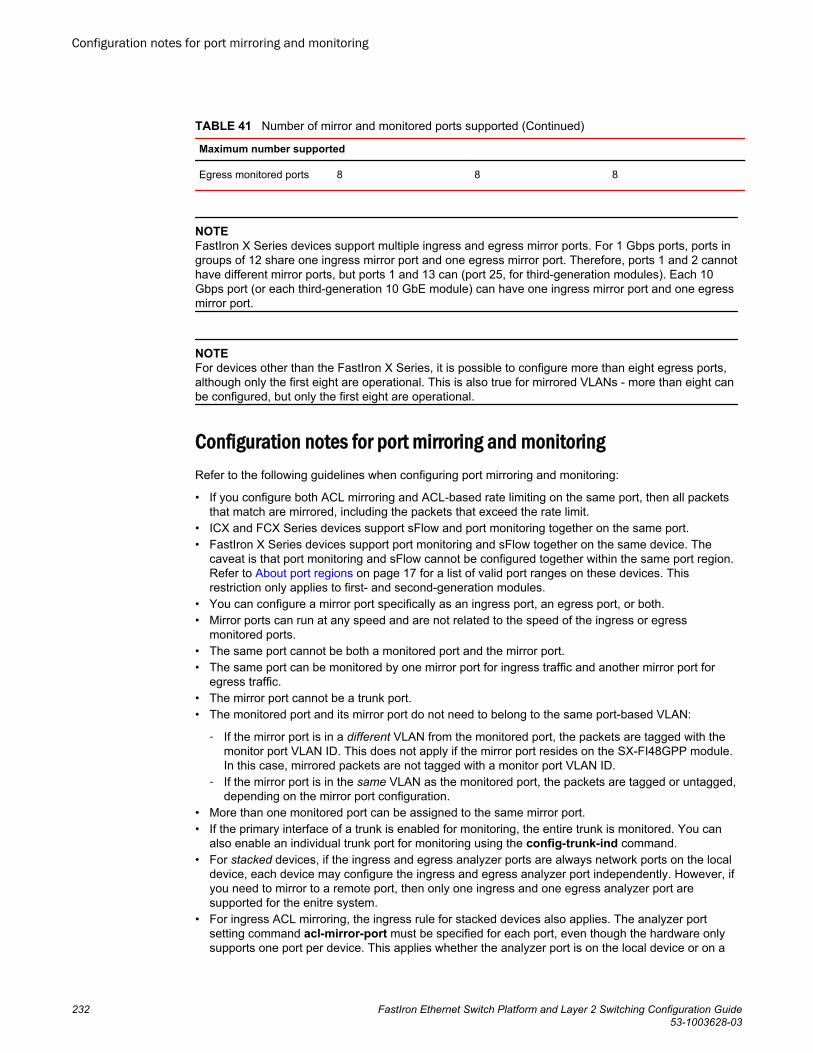
Number of mirror and monitored ports supported (Continued)TABLE 41
Maximum number supported
Egress monitored ports 8 8 8
NOTEFastIron X Series devices support multiple ingress and egress mirror ports. For 1 Gbps ports, ports ingroups of 12 share one ingress mirror port and one egress mirror port. Therefore, ports 1 and 2 cannothave different mirror ports, but ports 1 and 13 can (port 25, for third-generation modules). Each 10Gbps port (or each third-generation 10 GbE module) can have one ingress mirror port and one egressmirror port.
NOTEFor devices other than the FastIron X Series, it is possible to configure more than eight egress ports,although only the first eight are operational. This is also true for mirrored VLANs - more than eight canbe configured, but only the first eight are operational.
Configuration notes for port mirroring and monitoringRefer to the following guidelines when configuring port mirroring and monitoring:
• If you configure both ACL mirroring and ACL-based rate limiting on the same port, then all packetsthat match are mirrored, including the packets that exceed the rate limit.
• ICX and FCX Series devices support sFlow and port monitoring together on the same port.• FastIron X Series devices support port monitoring and sFlow together on the same device. The
caveat is that port monitoring and sFlow cannot be configured together within the same port region.Refer to About port regions on page 17 for a list of valid port ranges on these devices. Thisrestriction only applies to first- and second-generation modules.
• You can configure a mirror port specifically as an ingress port, an egress port, or both.• Mirror ports can run at any speed and are not related to the speed of the ingress or egress
monitored ports.• The same port cannot be both a monitored port and the mirror port.• The same port can be monitored by one mirror port for ingress traffic and another mirror port for
egress traffic.• The mirror port cannot be a trunk port.• The monitored port and its mirror port do not need to belong to the same port-based VLAN:
‐ If the mirror port is in a different VLAN from the monitored port, the packets are tagged with themonitor port VLAN ID. This does not apply if the mirror port resides on the SX-FI48GPP module.In this case, mirrored packets are not tagged with a monitor port VLAN ID.
‐ If the mirror port is in the same VLAN as the monitored port, the packets are tagged or untagged,depending on the mirror port configuration.
• More than one monitored port can be assigned to the same mirror port.• If the primary interface of a trunk is enabled for monitoring, the entire trunk is monitored. You can
also enable an individual trunk port for monitoring using the config-trunk-ind command.• For stacked devices, if the ingress and egress analyzer ports are always network ports on the local
device, each device may configure the ingress and egress analyzer port independently. However, ifyou need to mirror to a remote port, then only one ingress and one egress analyzer port aresupported for the enitre system.
• For ingress ACL mirroring, the ingress rule for stacked devices also applies. The analyzer portsetting command acl-mirror-port must be specified for each port, even though the hardware onlysupports one port per device. This applies whether the analyzer port is on the local device or on a
Configuration notes for port mirroring and monitoring
232 FastIron Ethernet Switch Platform and Layer 2 Switching Configuration Guide53-1003628-03
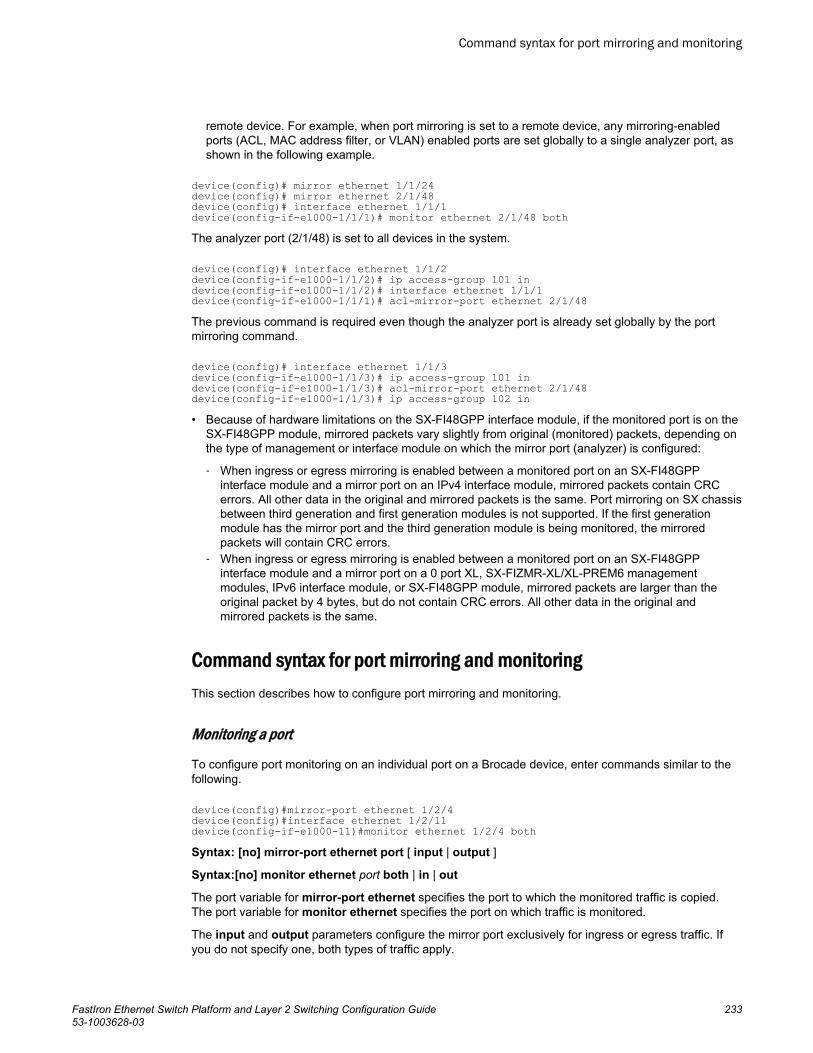
remote device. For example, when port mirroring is set to a remote device, any mirroring-enabledports (ACL, MAC address filter, or VLAN) enabled ports are set globally to a single analyzer port, asshown in the following example.
device(config)# mirror ethernet 1/1/24device(config)# mirror ethernet 2/1/48device(config)# interface ethernet 1/1/1device(config-if-e1000-1/1/1)# monitor ethernet 2/1/48 bothThe analyzer port (2/1/48) is set to all devices in the system.
device(config)# interface ethernet 1/1/2device(config-if-e1000-1/1/2)# ip access-group 101 indevice(config-if-e1000-1/1/2)# interface ethernet 1/1/1device(config-if-e1000-1/1/1)# acl-mirror-port ethernet 2/1/48The previous command is required even though the analyzer port is already set globally by the portmirroring command.
device(config)# interface ethernet 1/1/3device(config-if-e1000-1/1/3)# ip access-group 101 indevice(config-if-e1000-1/1/3)# acl-mirror-port ethernet 2/1/48device(config-if-e1000-1/1/3)# ip access-group 102 in• Because of hardware limitations on the SX-FI48GPP interface module, if the monitored port is on the
SX-FI48GPP module, mirrored packets vary slightly from original (monitored) packets, depending onthe type of management or interface module on which the mirror port (analyzer) is configured:
‐ When ingress or egress mirroring is enabled between a monitored port on an SX-FI48GPPinterface module and a mirror port on an IPv4 interface module, mirrored packets contain CRCerrors. All other data in the original and mirrored packets is the same. Port mirroring on SX chassisbetween third generation and first generation modules is not supported. If the first generationmodule has the mirror port and the third generation module is being monitored, the mirroredpackets will contain CRC errors.
‐ When ingress or egress mirroring is enabled between a monitored port on an SX-FI48GPPinterface module and a mirror port on a 0 port XL, SX-FIZMR-XL/XL-PREM6 managementmodules, IPv6 interface module, or SX-FI48GPP module, mirrored packets are larger than theoriginal packet by 4 bytes, but do not contain CRC errors. All other data in the original andmirrored packets is the same.
Command syntax for port mirroring and monitoringThis section describes how to configure port mirroring and monitoring.
Monitoring a port
To configure port monitoring on an individual port on a Brocade device, enter commands similar to thefollowing.
device(config)#mirror-port ethernet 1/2/4device(config)#interface ethernet 1/2/11device(config-if-e1000-11)#monitor ethernet 1/2/4 bothSyntax: [no] mirror-port ethernet port [ input | output ]
Syntax:[no] monitor ethernet port both | in | out
The port variable for mirror-port ethernet specifies the port to which the monitored traffic is copied.The port variable for monitor ethernet specifies the port on which traffic is monitored.
The input and output parameters configure the mirror port exclusively for ingress or egress traffic. Ifyou do not specify one, both types of traffic apply.
Command syntax for port mirroring and monitoring
FastIron Ethernet Switch Platform and Layer 2 Switching Configuration Guide 23353-1003628-03
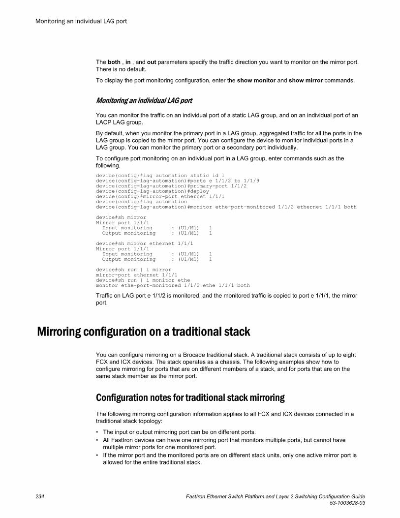
The both , in , and out parameters specify the traffic direction you want to monitor on the mirror port.There is no default.
To display the port monitoring configuration, enter the show monitor and show mirror commands.
Monitoring an individual LAG port
You can monitor the traffic on an individual port of a static LAG group, and on an individual port of anLACP LAG group.
By default, when you monitor the primary port in a LAG group, aggregated traffic for all the ports in theLAG group is copied to the mirror port. You can configure the device to monitor individual ports in aLAG group. You can monitor the primary port or a secondary port individually.
To configure port monitoring on an individual port in a LAG group, enter commands such as thefollowing.device(config)#lag automation static id 1device(config-lag-automation)#ports e 1/1/2 to 1/1/9 device(config-lag-automation)#primary-port 1/1/2device(config-lag-automation)#deploydevice(config)#mirror-port ethernet 1/1/1 device(config)#lag automationdevice(config-lag-automation)#monitor ethe-port-monitored 1/1/2 ethernet 1/1/1 bothdevice#sh mirrorMirror port 1/1/1 Input monitoring : (U1/M1) 1 Output monitoring : (U1/M1) 1device#sh mirror ethernet 1/1/1Mirror port 1/1/1 Input monitoring : (U1/M1) 1 Output monitoring : (U1/M1) 1device#sh run | i mirrormirror-port ethernet 1/1/1device#sh run | i monitor ethemonitor ethe-port-monitored 1/1/2 ethe 1/1/1 bothTraffic on LAG port e 1/1/2 is monitored, and the monitored traffic is copied to port e 1/1/1, the mirrorport.
Mirroring configuration on a traditional stackYou can configure mirroring on a Brocade traditional stack. A traditional stack consists of up to eightFCX and ICX devices. The stack operates as a chassis. The following examples show how toconfigure mirroring for ports that are on different members of a stack, and for ports that are on thesame stack member as the mirror port.
Configuration notes for traditional stack mirroringThe following mirroring configuration information applies to all FCX and ICX devices connected in atraditional stack topology:
• The input or output mirroring port can be on different ports.• All FastIron devices can have one mirroring port that monitors multiple ports, but cannot have
multiple mirror ports for one monitored port.• If the mirror port and the monitored ports are on different stack units, only one active mirror port is
allowed for the entire traditional stack.
Monitoring an individual LAG port
234 FastIron Ethernet Switch Platform and Layer 2 Switching Configuration Guide53-1003628-03
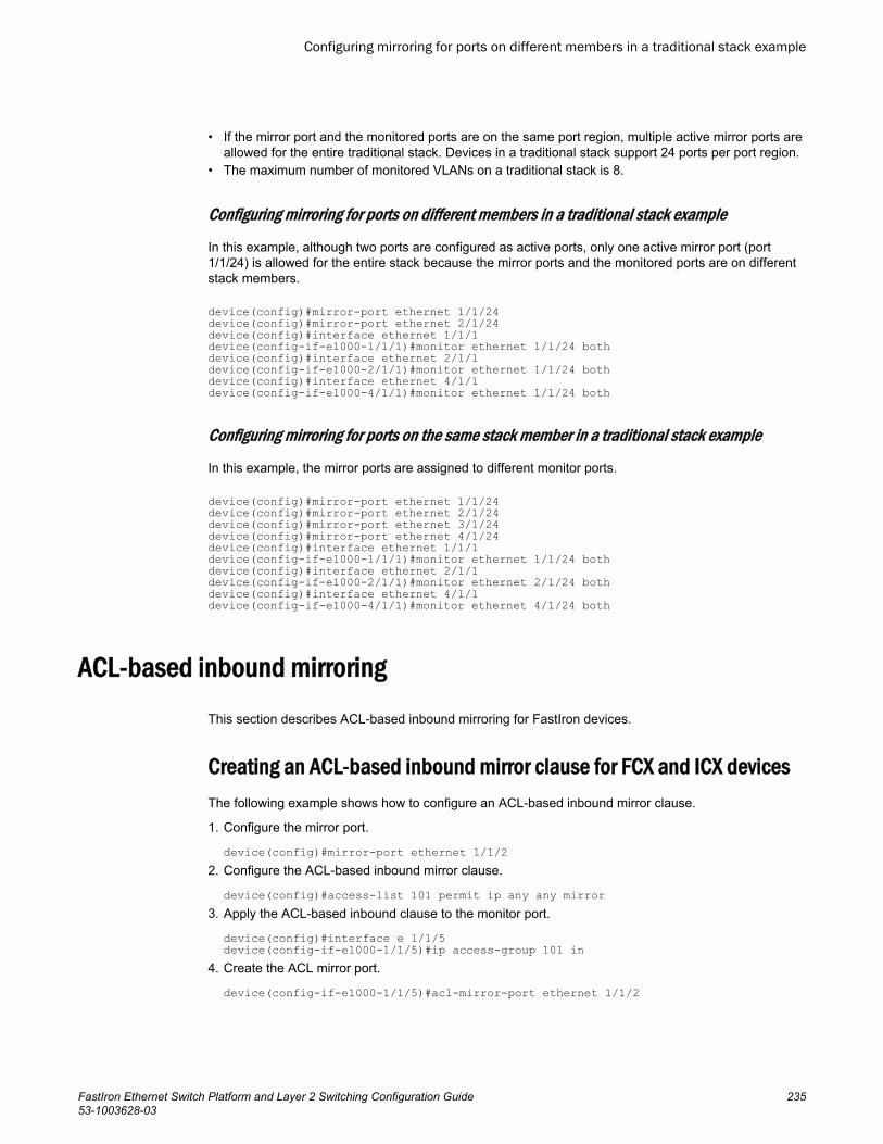
• If the mirror port and the monitored ports are on the same port region, multiple active mirror ports areallowed for the entire traditional stack. Devices in a traditional stack support 24 ports per port region.
• The maximum number of monitored VLANs on a traditional stack is 8.
Configuring mirroring for ports on different members in a traditional stack example
In this example, although two ports are configured as active ports, only one active mirror port (port1/1/24) is allowed for the entire stack because the mirror ports and the monitored ports are on differentstack members.
device(config)#mirror-port ethernet 1/1/24device(config)#mirror-port ethernet 2/1/24device(config)#interface ethernet 1/1/1device(config-if-e1000-1/1/1)#monitor ethernet 1/1/24 bothdevice(config)#interface ethernet 2/1/1device(config-if-e1000-2/1/1)#monitor ethernet 1/1/24 bothdevice(config)#interface ethernet 4/1/1device(config-if-e1000-4/1/1)#monitor ethernet 1/1/24 both
Configuring mirroring for ports on the same stack member in a traditional stack example
In this example, the mirror ports are assigned to different monitor ports.
device(config)#mirror-port ethernet 1/1/24device(config)#mirror-port ethernet 2/1/24device(config)#mirror-port ethernet 3/1/24device(config)#mirror-port ethernet 4/1/24device(config)#interface ethernet 1/1/1device(config-if-e1000-1/1/1)#monitor ethernet 1/1/24 bothdevice(config)#interface ethernet 2/1/1device(config-if-e1000-2/1/1)#monitor ethernet 2/1/24 bothdevice(config)#interface ethernet 4/1/1device(config-if-e1000-4/1/1)#monitor ethernet 4/1/24 both
ACL-based inbound mirroringThis section describes ACL-based inbound mirroring for FastIron devices.
Creating an ACL-based inbound mirror clause for FCX and ICX devicesThe following example shows how to configure an ACL-based inbound mirror clause.
1. Configure the mirror port.
device(config)#mirror-port ethernet 1/1/22. Configure the ACL-based inbound mirror clause.
device(config)#access-list 101 permit ip any any mirror3. Apply the ACL-based inbound clause to the monitor port.
device(config)#interface e 1/1/5device(config-if-e1000-1/1/5)#ip access-group 101 in
4. Create the ACL mirror port.
device(config-if-e1000-1/1/5)#acl-mirror-port ethernet 1/1/2
Configuring mirroring for ports on different members in a traditional stack example
FastIron Ethernet Switch Platform and Layer 2 Switching Configuration Guide 23553-1003628-03
To display ACL mirror settings, enter the show access-list all command.
device#show access-list allExtended IP access list 101permit ip any any mirror
ACL-based inbound mirror clauses for FastIron X Series devicesThe mirror parameter in an ACL clause causes the system to direct traffic that meets the clause to besent to a mirror port. Consider the following example.
device(config)#access-list 101 permit ip any any mirrorThe mirror parameter directs selected traffic to the mirrored port. Traffic mirroring is only supported onLayer 3 ACLs for FastIron X Series devices.
You can select traffic to be mirrored using a permit or deny clause on ports on the following interfacemodules:
• SX-FI-24GPP• SX-FI-24HF• SX-FI-2XG• SX-FI-8XG
On all other interface modules, you can select traffic to be mirrored using only a permit clause.
Destination mirror portYou can specify physical ports or a trunk to mirror traffic. If you complete the rest of the configurationbut do not specify a destination mirror port, the port-mirroring ACL is non-operational. This can beuseful if you want to be able to mirror traffic by a set criteria on demand. With this configuration, youconfigure a destination mirror port whenever you want the port-mirroring ACL to become operational.
The following sections describe how to specify a destination port for a port or a trunk, as well as thespecial considerations required when mirroring traffic from a virtual interface.
Specifying the destination mirror port for physical ports
When you want traffic that has been selected by ACL-based inbound mirroring to be mirrored, youmust configure a destination mirror port. This configuration is performed at the interface configurationlevel of the port with the traffic you are mirroring. The destination port must be the same for all ports ina port region as described in Ports from a port region must be mirrored to the same destination mirrorport.
In the following example, ACL mirroring traffic from port 1/1/1 is mirrored to port 1/1/3.
device(config)# interface ethernet 1/1/1device(config-if-e10000-1/1)# ACL-mirror-port ethernet 1/1/3Syntax: [no] ACL-mirror-port ethernet port
The port variable specifies the mirror port to which the monitored port traffic is copied.
Ports from a port region must be mirrored to the same destination mirror port
Port regions, as described in About port regions on page 17, are important when defining a destinationmirror port. This is because all traffic mirrored from any single port in a port region is mirrored to the
ACL-based inbound mirror clauses for FastIron X Series devices
236 FastIron Ethernet Switch Platform and Layer 2 Switching Configuration Guide53-1003628-03
same destination mirror port as traffic mirrored from any other port in the same port region. Forexample, ports 1/1/1 to 1/1/2 are in the same port region. If you configure ports 1/1/1 and 1/1/2 to mirrortheir traffic, they should use the same destination mirror port as shown in the following configuration.
device(config)# interface ethernet 1/1/1device(config-if-e10000-1/1/1)# ACL-mirror-port ethernet 1/2/3device(config)# interface ethernet 1/1/2device(config-if-e10000-1/1/2)# ACL-mirror-port ethernet 1/2/3If ports within the same port region are mirrored to different destination ports, the configuration isdisallowed, and an error message is generated, as shown in the following example.
device(config)# interface ethernet 1/1/1device(config-if-e10000-1/1/1)# ACL-mirror-port ethernet 1/4/3device(config)#interface ethernet 1/1/2device(config-if-e10000-1/1/2)# ACL-mirror-port ethernet 1/4/7Error - Inbound Mirror port 4/3 already configured for port region 1/1/1 - 1/1/12When a destination port is configured for any port within a port region, traffic from any ACL with amirroring clause assigned to any port in that port region is mirrored to that destination port. This willoccur even if a destination port is not explicitly configured for the port with the ACL configured. In thefollowing example, an ACL with a mirroring clause (101) is applied to a port (1/1/1). Another port in thesame region (1/1/3) has a destination port set (1/4/3). In this example, traffic generated from operationof ACL 101 is mirrored to port 1/4/3 even though a destination port has not explicitly been defined fortraffic from port 1/1/1.
device(config)# interface ethernet 1/1/1device(config-if-e10000-1/1/1)# ip access-group 101 indevice(config)# interface ethernet 1/1/3device(config-if-e10000-1/1/3)# ACL-mirror-port ethernet 1/4/3
NOTEIf a destination mirror port is not configured for any ports within the port region where the port-mirroringACL is configured, the ACL does not mirror the traffic but the ACL is applied to traffic on the port.
Specifying the destination mirror port for trunk ports
You can mirror the traffic that has been selected by ACL-based inbound mirroring from a trunk byconfiguring a destination port for the primary port within the trunk configuration, as shown in thefollowing example.
device(config)# trunk ethernet 1/1/1 to 1/1/4device(config)# interface ethernet 1/1/1device(config-if-e10000-1/1/1)# ACL-mirror-port ethernet 1/1/8Using this configuration, all trunk traffic is mirrored to port 1/1/8.
Limitations when configuring ACL-based mirroring with trunks
The config-trunk-ind command cannot operate with ACL-based mirroring:
• If a trunk is configured with the config-trunk-ind command, ACL-based mirroring will not be allowed.• If the config-trunk-ind command is added to a trunk, any ports that are configured for ACL-based
mirroring will have monitoring removed and the following message is displayed.
Trunk port monitoring, if any, has been removed.
Specifying the destination mirror port for trunk ports
FastIron Ethernet Switch Platform and Layer 2 Switching Configuration Guide 23753-1003628-03
If an individual port is configured for ACL-based mirroring, you cannot add it to a trunk. If you try to adda port that is configured for ACL-based mirroring to a trunk, the following message appears.
Note - ACL-mirror-port configuration is removed from port 2 in new trunk.
NOTEIf you want to add a port configured for ACL-based mirroring to a trunk, you must first remove theACL-mirror-port command from the port configuration. You can then add the port to a trunk that canthen be configured for ACL-based trunk mirroring.
Behavior of ACL-based mirroring when deleting trunks
If you delete a trunk that has ACL-based mirroring configured, the ACL-based mirroring configurationis configured on the individual ports that made up the trunk.
For example, if a trunk is configured as shown in the following example and is then deleted from theconfiguration as shown, each of the ports that previously was contained in the trunk is configured forACL-based mirroring.
device(config)# lag test static id 111device(config-lag-test)# ports ethernet 1/1/1 to 1/1/2device(config-lag-test)# primary-port 1/1/1device(config-lag-test)# deploydevice(config-if-e-1/1/1)# acl-mirror-port ethernet 1/1/38To delete the trunk, enter the following command.
device(config)#no lag test
Configuring ACL-based mirroring for ACLs bound to virtual interfaces
For configurations that have an ACL configured for ACL-based mirroring bound to a virtual interface,you must use the ACL-mirror-port command on a physical port that is a member of the same VLANas the virtual interface. Additionally, only traffic that arrives at ports that belong to the same port groupas the physical port where the ACL-mirror-port command has been used is mirrored. This follows thesame rules described in Ports from a port region must be mirrored to the same destination mirror porton page 236.
For example, in the following configuration, ports 1/4/1, 1/4/2, and 1/5/3 are in VLAN 10 with ve 10.Ports 1/4/1 and 1/4/2 belong to the same port group, while port 1/5/3 belongs to another port group.
device(config)# vlan 10 device(config-vlan-10)# tagged ethernet 1/4/1 to 1/4/2device(config-vlan-10)# tagged ethernet 1/5/3device(config-vlan-10)# router-interface ve 10device(config)# interface ethernet 1/4/1device(config-if-e10000-1/4/1)# ACL-mirror-port ethernet 1/5/1device(config)# interface ve 10device(config-vif-10)# ip address 10.10.10.254/24device(config-vif-10)# ip access-group 102 indevice(config)# access-list 102 permit ip any any mirrorIn this configuration, the ACL-mirror-port command is applied to port 1/4/1, which is a member of ve10. Because of this, ACL-based mirroring will only apply to VLAN 10 traffic that arrives on ports 1/4/1and 1/4/2. It will not apply to VLAN 10 traffic that arrives on port 1/5/3 because that port belongs to aport group different from ports 1/4/1 and 1/4/2. This is because if you apply ACL-based mirroring on anentire VE, and enable mirroring in only one port region, traffic that is in the same VE but on a port in adifferent port region will not be mirrored.
Configuring ACL-based mirroring for ACLs bound to virtual interfaces
238 FastIron Ethernet Switch Platform and Layer 2 Switching Configuration Guide53-1003628-03
To make the configuration apply ACL-based mirroring to VLAN 10 traffic arriving on port 1/5/3, you mustadd the following commands to the configuration.
device(config)# interface ethernet 1/5/3device(config-if-e10000-1/5/3)# ACL-mirror-port ethernet 1/5/1If a port is in both mirrored and non-mirrored VLANs, only traffic on the port from the mirrored VLAN ismirrored. For example, the following configuration adds VLAN 20 to the previous configuration. In thisexample, ports 1/4/1 and 1/4/2 are in both VLAN 10 and VLAN 20. ACL-based mirroring is only appliedto VLAN 10. Consequently, traffic that is on ports 1/4/1 and 1/4/2 that belongs to VLAN 20 will not bemirrored.
device(config)# vlan 10 device(config-vlan-10)# tagged ethernet 1/4/1 to 1/4/2device(config-vlan-10)# tagged ethernet 1/5/3device(config-vlan-10)# router-interface ve 10device(config)# vlan 20device(config-vlan-20)# tagged ethernet 1/4/1 to 1/4/2device(config)# interface ethernet 1/4/1device(config-if-e10000-1/4/1)# ACL-mirror-port ethernet 1/5/1device(config)# interface ve 10device(config-vif-10)# ip address 10.10.10.254/24device(config-vif-10)# ip access-group 102 indevice(config)# access-list 102 permit ip any any mirror
MAC address filter-based mirroring
NOTEThe MAC address filter-based mirroring feature is not supported on FastIron X Series devices.
This feature allows traffic entering an ingress port to be monitored from a mirror port connected to adata analyzer, based on specific source and destination MAC addresses. This feature supportsmirroring of inbound traffic only. Outbound mirroring is not supported.
MAC-filter-based mirroring allows a user to specify a particular stream of data for mirroring using a filter.This eliminates the need to analyze all incoming data to the monitored port. To configure MAC-filter-based mirroring, the user must perform three steps:
1. Define a mirror port2. Create a MAC address filter with a mirroring clause3. Apply the MAC address filter to an interface
Configuring MAC address filter-based mirroringComplete the following steps to configure MAC address filter-based mirroring.
1. Defining a mirror port
To activate mirroring on a port, use the mirror command in global configuration mode.
device(config)#mirror ethernet 1/1/14
MAC address filter-based mirroring
FastIron Ethernet Switch Platform and Layer 2 Switching Configuration Guide 23953-1003628-03
Configuration notes for defining a mirror port
• If there is no input mirror port configured, MAC-filter based mirroring does not take effect. It remainsin the configuration, but is not activated.
• MAC-filter-based mirroring can be enabled on a port at the same time as either port-based mirroringor VLAN-based mirroring. When port-based mirroring and MAC-filter-based mirroring are enabledon a port at the same time, the preference order is port-based mirroring followed by MAC-basedfiltering. When VLAN-based mirroring and MAC-filter-based mirroring are enabled on a port at thesame time, the preference order is VLAN-based mirroring and MAC-filter-based mirroring.
NOTEPort-based mirroring and VLAN-based mirroring can not be enabled on a port at the same time.
2. Creating a MAC address filter with a mirroring clause
The mirror keyword is added to MAC address filter clauses to direct desired traffic to the mirror port.In the following example, the MAC address filter directs traffic to a mirror port.
device(config)#mac filter 1 permit 0000.0011.2222 ffff.ffff.ffff 0000.0022.3333 ffff.ffff.fff mirrorIn this example, any flow matching the source address (SA) 0000.0011.2222 and the destinationaddress (DA) 0000.0022.3333 is mirrored. Other flows are not mirrored.
3. Applying the MAC address filter to an interface
Apply the MAC address filter to an interface using the mac-filter-group command.
device(config)#interface ethernet 1/1/1device(config-if-e10000-1/1/1)#mac filter-group 1
4. Configuring the monitor port to use the mirror port
device(config)# interface ethernet 1/1/5device(config-if-e10000-1/1/5)# acl-mirror-port ethernet 1/1/14
VLAN-based mirroring
NOTEVLAN-based mirroring is supported on FastIron X Series devices equipped with third generation orlater modules, ICX 6650, ICX 7750, ICX 7450 and ICX 7250 devices. Refer to VLAN-based mirroringon page 242.
The VLAN-based mirroring feature allows users to monitor all incoming traffic in one or more VLANsby sending a mirror image of that traffic to a configured mirror port. This feature meets therequirements of CALEA (Communications Assistance for Law Enforcement Act of 1994).
2. Creating a MAC address filter with a mirroring clause
240 FastIron Ethernet Switch Platform and Layer 2 Switching Configuration Guide53-1003628-03
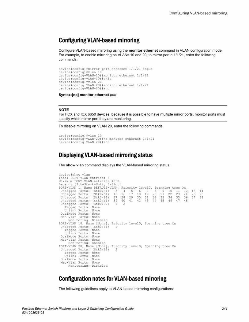
Configuring VLAN-based mirroringConfigure VLAN-based mirroring using the monitor ethernet command in VLAN configuration mode.For example, to enable mirroring on VLANs 10 and 20, to mirror port e 1/1/21, enter the followingcommands.
device(config)#mirror-port ethernet 1/1/21 inputdevice(config)#vlan 10device(config-VLAN-10)#monitor ethernet 1/1/21device(config-VLAN-10)#exitdevice(config)#vlan 20device(config-VLAN-20)#monitor ethernet 1/1/21device(config-VLAN-20)#endSyntax:[no] monitor ethernet port
NOTEFor FCX and ICX 6650 devices, because it is possible to have multiple mirror ports, monitor ports mustspecify which mirror port they are monitoring.
To disable mirroring on VLAN 20, enter the following commands.
device(config)#vlan 20device(config-VLAN-20)#no monitor ethernet 1/1/21device(config-VLAN-20)#end
Displaying VLAN-based mirroring statusThe show vlan command displays the VLAN-based mirroring status.
device#show vlanTotal PORT-VLAN entries: 4Maximum PORT-VLAN entries: 4060Legend: [Stk=Stack-Unit, S=Slot]PORT-VLAN 1, Name DEFAULT-VLAN, Priority level0, Spanning tree On Untagged Ports: (Stk0/S1) 3 4 5 6 7 8 9 10 11 12 13 14 Untagged Ports: (Stk0/S1) 15 16 17 18 19 20 21 22 23 24 25 26 Untagged Ports: (Stk0/S1) 27 28 29 30 31 32 33 34 35 36 37 38 Untagged Ports: (Stk0/S1) 39 40 41 42 43 44 45 46 47 48 Untagged Ports: (Stk0/S2) 1 2 Tagged Ports: None Uplink Ports: None DualMode Ports: None Mac-Vlan Ports: None Monitoring: DisabledPORT-VLAN 10, Name [None], Priority level0, Spanning tree On Untagged Ports: (Stk0/S1) 1 Tagged Ports: None Uplink Ports: None DualMode Ports: None Mac-Vlan Ports: None Monitoring: EnabledPORT-VLAN 20, Name [None], Priority level0, Spanning tree On Untagged Ports: (Stk0/S1) 2 Tagged Ports: None Uplink Ports: None DualMode Ports: None Mac-Vlan Ports: None Monitoring: Disabled
Configuration notes for VLAN-based mirroringThe following guidelines apply to VLAN-based mirroring configurations:
Configuring VLAN-based mirroring
FastIron Ethernet Switch Platform and Layer 2 Switching Configuration Guide 24153-1003628-03

• A VLAN must have at least one port member configured before monitoring can be configured.• Multiple VLANs can have monitoring enabled at the same time, and the maximum number of
monitor-configured VLANs is 8.• The mirror port is subject to the same scheduling and bandwidth management as the other ports in
the system. If the amount of traffic being sent to the mirror port exceeds the available bandwidth,some of that traffic may be dropped.
• All incoming traffic (tagged and untagged) in the VLAN is mirrored. mirroring is "as-is", and is notaffected by the configuration of the mirror port itself. Incoming tagged traffic is sent out tagged andincoming untagged traffic is sent out untagged, regardless of which VLANs the mirror port belongsto, and whether the mirror port is tagged or untagged.
• VLAN-based mirroring is supported on Layer 2 and Layer 3 images.
VLAN-based mirroringWIth the new FastIron X Series of modules, the sFlow processing has been separated from the packetmirroring functionality. This allows for support of VLAN-based mirroring on the FastIron X Seriesdevices. The packet processor on the FastIron X Series of modules also allows for egress VLAN-based mirroring. In order for VLAN-based monitoring to function, the FastIron X Series must have onlythe following SX modules installed.
The following interface modules are new to the FastIron X Series:
• SX-FI-24GPP• SX-FI-24HF• SX-FI-2XG• SX-FI-8XG• SX-FI48GPP
NOTEEgress VLAN-based mirroring is not currently supported on the stacking platforms.
The FastIron X Series of modules are capable of monitoring 4096 VLANs. In a chassis environment,this introduces restrictions to the number of ports that can be configured as mirror ports. Because asingle VLAN can contain 384 untagged ports (24 per slot) if that VLAN is configured for monitoring,every device must have an identical number of corresponding analyzer ports. However, the egressmirror-port and ingress mirror-port do not have to be the same. You can use two separate ports.
This introduces restrictions on port-based mirroring coexisting with VLAN-based mirroring. Port-basedmirroring allows for multiple ports to be configured as mirror-ports. However, once a particular portbelonging to a particular device is configured for monitoring to a specific mirror-port, no other mirror-port can be used to monitor any other port on that device. This restriction has been extended to VLAN-based mirroring, with one caveat: only one mirror-port in either direction at a time can exist within thesystem. Refer to About port regions on page 17 for a list of valid port ranges on these devices.
VLAN-based mirroring is also supported on ICX 6650 devices.
Restrictions and capabilities of VLAN-based mirroring
The following is a list of restrictions and capabilities:
• Only the modules that support VLAN-based mirroring should be installed.• There can be only one input or output mirror-port configured in the system at a time.• The amount of traffic mirrored is limited by the bandwidth of the mirror-port.• The maximum amount of egress traffic that can be mirrored is further limited by the bandwidth of
the loopback port, which is 10 Gbps.
VLAN-based mirroring
242 FastIron Ethernet Switch Platform and Layer 2 Switching Configuration Guide53-1003628-03
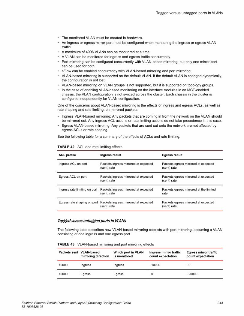
• The monitored VLAN must be created in hardware.• An ingress or egress mirror-port must be configured when monitoring the ingress or egress VLAN
traffic.• A maximum of 4096 VLANs can be monitored at a time.• A VLAN can be monitored for ingress and egress traffic concurrently.• Port mirroring can be configured concurrently with VLAN-based mirroring, but only one mirror-port
can be used for both.• sFlow can be enabled concurrently with VLAN-based mirroring and port mirroring.• VLAN-based mirroring is supported on the default VLAN. If the default VLAN is changed dynamically,
the configuration is not lost.• VLAN-based mirroring on VLAN groups is not supported, but it is supported on topology groups.• In the case of enabling VLAN-based monitoring on the interface modules in an MCT-enabled
chassis, the VLAN configuration is not synced across the cluster. Each chassis in the cluster isconfigured independently for VLAN configuration.
One of the concerns about VLAN-based mirroring is the effects of ingress and egress ACLs, as well asrate shaping and rate limiting, on mirrored packets:
• Ingress VLAN-based mirroring: Any packets that are coming in from the network on the VLAN shouldbe mirrored out. Any ingress ACL actions or rate limiting actions do not take precedence in this case.
• Egress VLAN-based mirroring: Any packets that are sent out onto the network are not affected byegress ACLs or rate shaping.
See the following table for a summary of the effects of ACLs and rate limiting.
ACL and rate limiting effects TABLE 42
ACL profile Ingress result Egress result
Ingress ACL on port Packets ingress mirrored at expected(sent) rate
Packets egress mirrored at expected(sent) rate
Egress ACL on port Packets ingress mirrored at expected(sent) rate
Packets egress mirrored at expected(sent) rate
Ingress rate limiting on port Packets ingress mirrored at expected(sent) rate
Packets egress mirrored at the limitedrate
Egress rate shaping on port Packets ingress mirrored at expected(sent) rate
Packets egress mirrored at expected(sent) rate
Tagged versus untagged ports in VLANs
The following table describes how VLAN-based mirroring coexists with port mirroring, assuming a VLANconsisting of one ingress and one egress port.
VLAN-based mirroring and port mirroring effects TABLE 43
Packets sent VLAN-basedmirroring direction
Which port in VLANis monitored
Ingress mirror trafficcount expectation
Egress mirror trafficcount expectation
10000 Ingress Ingress ~10000 ~0
10000 Egress Egress ~0 ~20000
Tagged versus untagged ports in VLANs
FastIron Ethernet Switch Platform and Layer 2 Switching Configuration Guide 24353-1003628-03
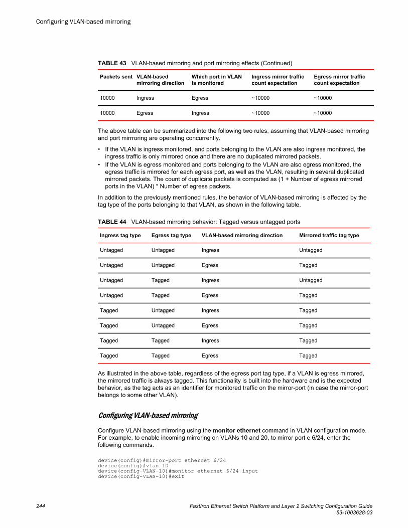
VLAN-based mirroring and port mirroring effects (Continued)TABLE 43
Packets sent VLAN-basedmirroring direction
Which port in VLANis monitored
Ingress mirror trafficcount expectation
Egress mirror trafficcount expectation
10000 Ingress Egress ~10000 ~10000
10000 Egress Ingress ~10000 ~10000
The above table can be summarized into the following two rules, assuming that VLAN-based mirroringand port mirrroring are operating concurrently.
• If the VLAN is ingress monitored, and ports belonging to the VLAN are also ingress monitored, theingress traffic is only mirrored once and there are no duplicated mirrored packets.
• If the VLAN is egress monitored and ports belonging to the VLAN are also egress monitored, theegress traffic is mirrored for each egress port, as well as the VLAN, resulting in several duplicatedmirrored packets. The count of duplicate packets is computed as (1 + Number of egress mirroredports in the VLAN) * Number of egress packets.
In addition to the previously mentioned rules, the behavior of VLAN-based mirroring is affected by thetag type of the ports belonging to that VLAN, as shown in the following table.
VLAN-based mirroring behavior: Tagged versus untagged ports TABLE 44
Ingress tag type Egress tag type VLAN-based mirroring direction Mirrored traffic tag type
Untagged Untagged Ingress Untagged
Untagged Untagged Egress Tagged
Untagged Tagged Ingress Untagged
Untagged Tagged Egress Tagged
Tagged Untagged Ingress Tagged
Tagged Untagged Egress Tagged
Tagged Tagged Ingress Tagged
Tagged Tagged Egress Tagged
As illustrated in the above table, regardless of the egress port tag type, if a VLAN is egress mirrored,the mirrored traffic is always tagged. This functionality is built into the hardware and is the expectedbehavior, as the tag acts as an identifier for monitored traffic on the mirror-port (in case the mirror-portbelongs to some other VLAN).
Configuring VLAN-based mirroring
Configure VLAN-based mirroring using the monitor ethernet command in VLAN configuration mode.For example, to enable incoming mirroring on VLANs 10 and 20, to mirror port e 6/24, enter thefollowing commands.
device(config)#mirror-port ethernet 6/24device(config)#vlan 10device(config-VLAN-10)#monitor ethernet 6/24 inputdevice(config-VLAN-10)#exit
Configuring VLAN-based mirroring
244 FastIron Ethernet Switch Platform and Layer 2 Switching Configuration Guide53-1003628-03
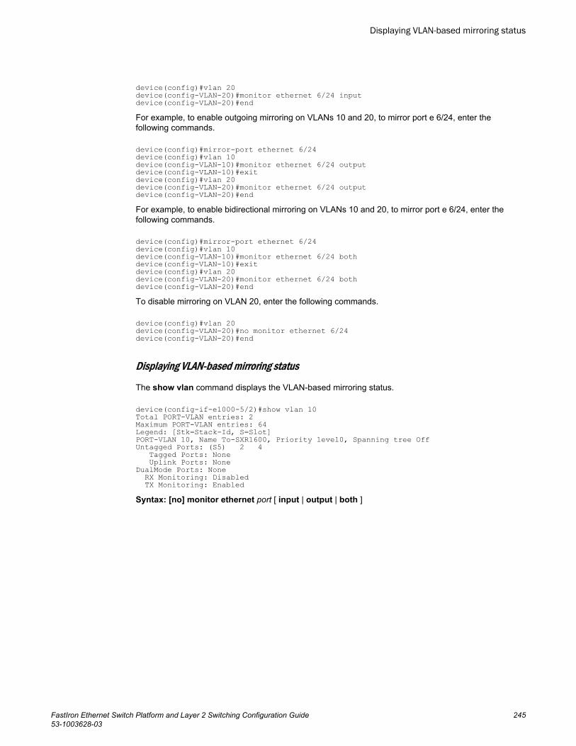
device(config)#vlan 20device(config-VLAN-20)#monitor ethernet 6/24 inputdevice(config-VLAN-20)#endFor example, to enable outgoing mirroring on VLANs 10 and 20, to mirror port e 6/24, enter thefollowing commands.
device(config)#mirror-port ethernet 6/24 device(config)#vlan 10device(config-VLAN-10)#monitor ethernet 6/24 outputdevice(config-VLAN-10)#exitdevice(config)#vlan 20device(config-VLAN-20)#monitor ethernet 6/24 outputdevice(config-VLAN-20)#endFor example, to enable bidirectional mirroring on VLANs 10 and 20, to mirror port e 6/24, enter thefollowing commands.
device(config)#mirror-port ethernet 6/24 device(config)#vlan 10device(config-VLAN-10)#monitor ethernet 6/24 bothdevice(config-VLAN-10)#exitdevice(config)#vlan 20device(config-VLAN-20)#monitor ethernet 6/24 bothdevice(config-VLAN-20)#endTo disable mirroring on VLAN 20, enter the following commands.
device(config)#vlan 20device(config-VLAN-20)#no monitor ethernet 6/24device(config-VLAN-20)#end
Displaying VLAN-based mirroring status
The show vlan command displays the VLAN-based mirroring status.
device(config-if-e1000-5/2)#show vlan 10Total PORT-VLAN entries: 2Maximum PORT-VLAN entries: 64Legend: [Stk=Stack-Id, S=Slot]PORT-VLAN 10, Name To-SXR1600, Priority level0, Spanning tree OffUntagged Ports: (S5) 2 4 Tagged Ports: None Uplink Ports: NoneDualMode Ports: None RX Monitoring: Disabled TX Monitoring: EnabledSyntax: [no] monitor ethernet port [ input | output | both ]
Displaying VLAN-based mirroring status
FastIron Ethernet Switch Platform and Layer 2 Switching Configuration Guide 24553-1003628-03

Displaying VLAN-based mirroring status
246 FastIron Ethernet Switch Platform and Layer 2 Switching Configuration Guide53-1003628-03
Spanning Tree Protocol
● STP overview................................................................................................................ 247● Standard STP parameter configuration.........................................................................247● STP feature configuration............................................................................................. 261● PVST/PVST+ compatibility............................................................................................312● PVRST compatibility..................................................................................................... 318● BPDU guard.................................................................................................................. 318● Root guard.................................................................................................................... 321● Designated Protection...................................................................................................322● Error disable recovery................................................................................................... 323● 802.1s Multiple Spanning Tree Protocol....................................................................... 325
STP overviewThe Spanning Tree Protocol (STP) eliminates Layer 2 loops in networks, by selectively blocking someports and allowing other ports to forward traffic, based on global (bridge) and local (port) parametersyou can configure.
STP related features, such as RSTP and PVST, extend the operation of standard STP, enabling you tofine-tune standard STP and avoid some of its limitations.
You can enable or disable STP on a global basis (for the entire device), a port-based VLAN basis (forthe individual Layer 2 broadcast domain), or an individual port basis.
Configuration procedures are provided for the standard STP bridge and port parameters.
Standard STP parameter configurationBrocade Layer 2 Switches and Layer 3 Switches support standard STP as described in the IEEE802.1D specification. STP is enabled by default on Layer 2 Switches but disabled by default on Layer 3Switches.
By default, each port-based VLAN on a Brocade device runs a separate spanning tree (a separateinstance of STP). A Brocade device has one port-based VLAN (VLAN 1) by default that contains all thedevice ports. Thus, by default each Brocade device has one spanning tree. However, if you configureadditional port-based VLANs on a Brocade device, then each of those VLANs on which STP is enabledand VLAN 1 all run separate spanning trees.
If you configure a port-based VLAN on the device, the VLAN has the same STP state as the defaultSTP state on the device. Thus, on Layer 2 Switches, new VLANs have STP enabled by default. OnLayer 3 Switches, new VLANs have STP disabled by default. You can enable or disable STP in eachVLAN separately. In addition, you can enable or disable STP on individual ports.
FastIron Ethernet Switch Platform and Layer 2 Switching Configuration Guide 24753-1003628-03
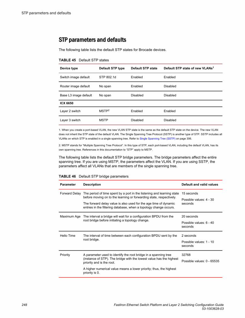
STP parameters and defaultsThe following table lists the default STP states for Brocade devices.
Default STP states TABLE 45
Device type Default STP type Default STP state Default STP state of new VLANs1
Switch image default STP 802.1d Enabled Enabled
Router image default No span Enabled Disabled
Base L3 image default No span Disabled Disabled
ICX 6650
Layer 2 switch MSTP2 Enabled Enabled
Layer 3 switch MSTP Disabled Disabled
1. When you create a port-based VLAN, the new VLAN STP state is the same as the default STP state on the device. The new VLANdoes not inherit the STP state of the default VLAN. The Single Spanning Tree Protocol (SSTP) is another type of STP. SSTP includes allVLANs on which STP is enabled in a single spanning tree. Refer to Single Spanning Tree (SSTP) on page 306.
2. MSTP stands for “Multiple Spanning Tree Protocol”. In this type of STP, each port-based VLAN, including the default VLAN, has itsown spanning tree. References in this documentation to “STP” apply to MSTP.
The following table lists the default STP bridge parameters. The bridge parameters affect the entirespanning tree. If you are using MSTP, the parameters affect the VLAN. If you are using SSTP, theparameters affect all VLANs that are members of the single spanning tree.
Default STP bridge parameters TABLE 46
Parameter Description Default and valid values
Forward Delay The period of time spent by a port in the listening and learning statebefore moving on to the learning or forwarding state, respectively.
The forward delay value is also used for the age time of dynamicentries in the filtering database, when a topology change occurs.
15 seconds
Possible values: 4 - 30seconds
Maximum Age The interval a bridge will wait for a configuration BPDU from theroot bridge before initiating a topology change.
20 seconds
Possible values: 6 - 40seconds
Hello Time The interval of time between each configuration BPDU sent by theroot bridge.
2 seconds
Possible values: 1 - 10seconds
Priority A parameter used to identify the root bridge in a spanning tree(instance of STP). The bridge with the lowest value has the highestpriority and is the root.
A higher numerical value means a lower priority; thus, the highestpriority is 0.
32768
Possible values: 0 - 65535
STP parameters and defaults
248 FastIron Ethernet Switch Platform and Layer 2 Switching Configuration Guide53-1003628-03
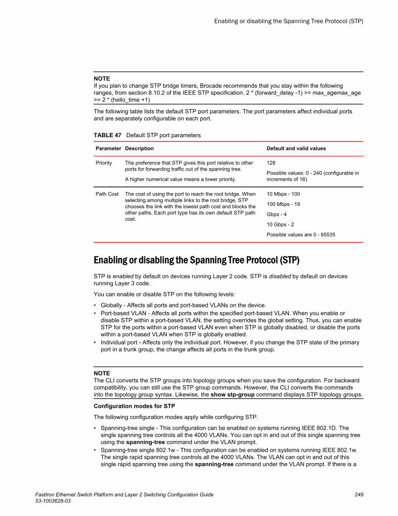
NOTEIf you plan to change STP bridge timers, Brocade recommends that you stay within the followingranges, from section 8.10.2 of the IEEE STP specification. 2 * (forward_delay -1) >= max_agemax_age>= 2 * (hello_time +1)
The following table lists the default STP port parameters. The port parameters affect individual portsand are separately configurable on each port.
Default STP port parameters TABLE 47
Parameter Description Default and valid values
Priority The preference that STP gives this port relative to otherports for forwarding traffic out of the spanning tree.
A higher numerical value means a lower priority.
128
Possible values: 0 - 240 (configurable inincrements of 16)
Path Cost The cost of using the port to reach the root bridge. Whenselecting among multiple links to the root bridge, STPchooses the link with the lowest path cost and blocks theother paths. Each port type has its own default STP pathcost.
10 Mbps - 100
100 Mbps - 19
Gbps - 4
10 Gbps - 2
Possible values are 0 - 65535
Enabling or disabling the Spanning Tree Protocol (STP)STP is enabled by default on devices running Layer 2 code. STP is disabled by default on devicesrunning Layer 3 code.
You can enable or disable STP on the following levels:
• Globally - Affects all ports and port-based VLANs on the device.• Port-based VLAN - Affects all ports within the specified port-based VLAN. When you enable or
disable STP within a port-based VLAN, the setting overrides the global setting. Thus, you can enableSTP for the ports within a port-based VLAN even when STP is globally disabled, or disable the portswithin a port-based VLAN when STP is globally enabled.
• Individual port - Affects only the individual port. However, if you change the STP state of the primaryport in a trunk group, the change affects all ports in the trunk group.
NOTEThe CLI converts the STP groups into topology groups when you save the configuration. For backwardcompatibility, you can still use the STP group commands. However, the CLI converts the commandsinto the topology group syntax. Likewise, the show stp-group command displays STP topology groups.
Configuration modes for STP
The following configuration modes apply while configuring STP.
• Spanning-tree single - This configuration can be enabled on systems running IEEE 802.1D. Thesingle spanning tree controls all the 4000 VLANs. You can opt in and out of this single spanning treeusing the spanning-tree command under the VLAN prompt.
• Spanning-tree single 802.1w - This configuration can be enabled on systems running IEEE 802.1w.The single rapid spanning tree controls all the 4000 VLANs. The VLAN can opt in and out of thissingle rapid spanning tree using the spanning-tree command under the VLAN prompt. If there is a
Enabling or disabling the Spanning Tree Protocol (STP)
FastIron Ethernet Switch Platform and Layer 2 Switching Configuration Guide 24953-1003628-03
“spanning-tree” configuration under the VLAN, that VLAN will be with that single 802.1w instance’scontrol, which implies that the VLAN traffic is subject to blocking or forwarding by that spanning treeinstance.
• Per VLAN spanning tree - In this configuration mode you can turn on 802.1D or 802.1w (RapidSpanning Tree) at the VLAN level individually.
Enabling or disabling STP globally
Use the following method to enable or disable STP on a device on which you have not configured port-based VLANs.
NOTEWhen you configure a VLAN, the VLAN inherits the global STP settings. However, once you begin todefine a VLAN, you can no longer configure standard STP parameters globally using the CLI. Fromthat point on, you can configure STP only within individual VLANs.
To enable STP for all ports in all VLANs on a Brocade device, enter the spanning-tree command.
device(config)# spanning-treeThe spanning-tree command enables a separate spanning tree in each VLAN, including the defaultVLAN.
Syntax: [no] spanning-tree
To set system maximum value for number of spanning tree instances, enter the command such as thefollowing:
Brocade (config)# system-max spanning-tree 254Syntax: system-max spanning-tree number
NOTEThe number of spanning tree instances ranges from 1 - 254, with 32 as the default.
Enabling or disabling STP in a port-based VLAN
Use the following procedure to disable or enable STP on a device on which you have configured aport-based VLAN. Changing the STP state in a VLAN affects only that VLAN.
To enable STP for all ports in a port-based VLAN, enter commands such as the following.
device(config)#vlan 10device(config-vlan-10)#spanning-treeSyntax: [no] spanning-tree
Enabling or disabling STP on an individual port
Use the following procedure to disable or enable STP on an individual port.
NOTEIf you change the STP state of the primary port in a trunk group, it affects all ports in the trunk group.
Enabling or disabling STP globally
250 FastIron Ethernet Switch Platform and Layer 2 Switching Configuration Guide53-1003628-03
To enable STP on an individual port, enter commands such as the following.
device(config)# interface 1/1/1device(config-if-e1000-1/1/1)# spanning-treeSyntax: [no] spanning-tree
Changing STP bridge and port parametersTable 46 on page 248 and Table 47 on page 249 list the default STP parameters. If you need to changethe default value for an STP parameter, use the following procedures.
Changing STP bridge parameters
NOTEIf you plan to change STP bridge timers, Brocade recommends that you stay within the followingranges, from section 8.10.2 of the IEEE STP specification. 2 * (forward_delay -1) >= max_agemax_age>= 2 * (hello_time +1)
To change a STP bridge priority on a Brocade device to the highest value to make the device the rootbridge, enter the following command.
device(config)#spanning-tree priority 0The command in this example changes the priority on a device on which you have not configured port-based VLANs. The change applies to the default VLAN. If you have configured a port-based VLAN onthe device, you can configure the parameters only at the configuration level for individual VLANs. Entercommands such as the following.
device(config)#vlan 20device(config-vlan-20)#spanning-tree priority 0To make this change in the default VLAN, enter the following commands.
device(config)#vlan 1device(config-vlan-1)#spanning-tree priority 0Syntax: [no] spanning-tree [ forward-delay value] | [hello-time value] | [maximum-age value] |[priority value]
The forward-delayvalue parameter specifies the forward delay and can be a value from 4 - 30seconds. The default is 15 seconds.
NOTEYou can configure a Brocade device for faster convergence (including a shorter forward delay) usingFast Span or Fast Uplink Span. Refer to STP feature configuration on page 261.
The hello-time value parameter specifies the hello time and can be a value from 1 - 10 seconds. Thedefault is 2 seconds.
NOTEThis parameter applies only when this device or VLAN is the root bridge for its spanning tree.
Changing STP bridge and port parameters
FastIron Ethernet Switch Platform and Layer 2 Switching Configuration Guide 25153-1003628-03
The maximum-age value parameter specifies the amount of time the device waits for receipt of aconfiguration BPDU from the root bridge before initiating a topology change. You can specify from 6 -40 seconds. The default is 20 seconds.
The priority value parameter specifies the priority and can be a value from 0 - 65535. A highernumerical value means a lower priority. Thus, the highest priority is 0. The default is 32768.
You can specify some or all of these parameters on the same command line. If you specify more thanone parameter, you must specify them in the order shown above, from left to right.
Changing STP port parameters
To change the path and priority costs for a port, enter commands such as the following.
device(config)#vlan 10device(config-vlan-10)#spanning-tree ethernet 5 path-cost 15 priority 64Syntax: spanning-tree ethernet port path-cost value | priority value | disable | enable
The path-cost value parameter specifies the port cost as a path to the spanning tree root bridge. STPprefers the path with the lowest cost. You can specify a value from 0 - 65535.
The default depends on the port type:
• 10 Mbps - 100• 100 Mbps - 19• Gbps - 4• 10 Gbps - 2• The priorityvalue parameter specifies the preference that STP gives this port relative to other ports
for forwarding traffic out of the spanning tree. If you are upgrading a device that has a configurationsaved under an earlier software release, and the configuration contains a value from 0 - 7 for a portSTP priority, the software changes the priority to the default when you save the configuration whilerunning the new release.
The disable and enable parameter disables or re-enables STP on the port. The STP state changeaffects only this VLAN. The port STP state in other VLANs is not changed.
STP protection enhancementSTP protection provides the ability to prohibit an end station from initiating or participating in an STPtopology change.
The 802.1W Spanning Tree Protocol (STP) detects and eliminates logical loops in a redundantnetwork by selectively blocking some data paths (ports) and allowing only the best data paths toforward traffic.
In an STP environment, switches, end stations, and other Layer 2 devices use Bridge Protocol DataUnits (BPDUs) to exchange information that STP will use to determine the best path for data flow.When a Layer 2 device is powered ON and connected to the network, or when a Layer 2 device goesdown, it sends out an STP BPDU, triggering an STP topology change.
In some instances, it is unnecessary for a connected device, such as an end station, to initiate orparticipate in an STP topology change. In this case, you can enable the STP Protection feature on theBrocade port to which the end station is connected. STP Protection disables the connected deviceability to initiate or participate in an STP topology change, by dropping all BPDUs received from theconnected device.
Changing STP port parameters
252 FastIron Ethernet Switch Platform and Layer 2 Switching Configuration Guide53-1003628-03
Enabling STP protection
You can enable STP Protection on a per-port basis.
To prevent an end station from initiating or participating in STP topology changes, enter the followingcommand at the Interface level of the CLI.
device#(config) interface ethernet 2device#(config-if-e1000-2)#stp-protectThis command causes the port to drop STP BPDUs sent from the device on the other end of the link.
Syntax: [no] stp-protect
Enter the no form of the command to disable STP protection on the port.
Clearing BPDU drop counters
For each port that has STP Protection enabled, the Brocade device counts and records the number ofdropped BPDUs. You can use CLI commands to clear the BPDU drop counters for all ports on thedevice, or for a specific port on the device.
To clear the BPDU drop counters for all ports on the device that have STP Protection enabled, enter thefollowing command at the Global CONFIG level of the CLI.
device(config)#clear stp-protect-statisticsTo clear the BPDU drop counter for a specific port that has STP Protection enabled, enter the followingcommand at the Global CONFIG level of the CLI.
device#clear stp-protect-statistics e 2Syntax: clear stp-protect-statistics [ethernet port]
Viewing the STP Protection Configuration
You can view the STP Protection configuration for all ports on a device, or for a specific port only. Theshow stp-protect command output shows the port number on which STP Protection is enabled, andthe number of BPDUs dropped by each port.
To view the STP Protection configuration for all ports on the device, enter the following command at anylevel of the CLI.
device#show stp-protectPort ID BPDU Drop Count 3 478 5 213 6 0 12 31To view STP Protection configuration for a specific port, enter the following command at any level of theCLI.
device#show stp-protect e 3STP-protect is enabled on port 3. BPDU drop count is 478If you enter the show stp-protect command for a port that does not have STP protection enabled, thefollowing message displays on the console.
device#show stp-protect e 4STP-protect is not enabled on port 4.
Enabling STP protection
FastIron Ethernet Switch Platform and Layer 2 Switching Configuration Guide 25353-1003628-03
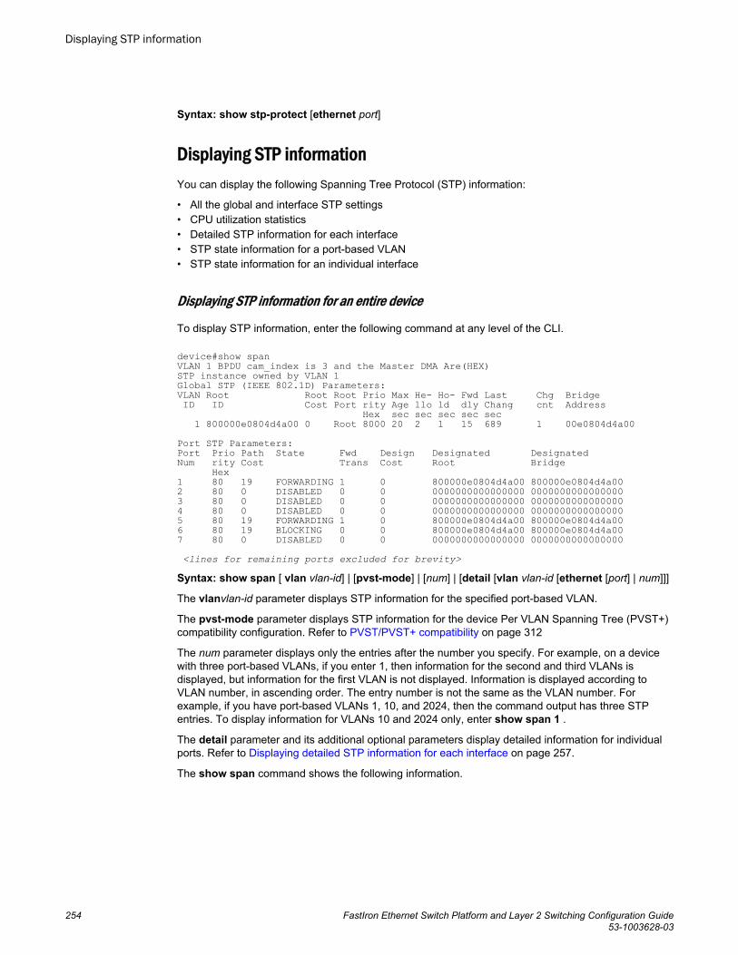
Syntax: show stp-protect [ethernet port]
Displaying STP informationYou can display the following Spanning Tree Protocol (STP) information:
• All the global and interface STP settings• CPU utilization statistics• Detailed STP information for each interface• STP state information for a port-based VLAN• STP state information for an individual interface
Displaying STP information for an entire device
To display STP information, enter the following command at any level of the CLI.
device#show spanVLAN 1 BPDU cam_index is 3 and the Master DMA Are(HEX)STP instance owned by VLAN 1Global STP (IEEE 802.1D) Parameters:VLAN Root Root Root Prio Max He- Ho- Fwd Last Chg Bridge ID ID Cost Port rity Age llo ld dly Chang cnt Address Hex sec sec sec sec sec 1 800000e0804d4a00 0 Root 8000 20 2 1 15 689 1 00e0804d4a00 Port STP Parameters:Port Prio Path State Fwd Design Designated DesignatedNum rity Cost Trans Cost Root Bridge Hex1 80 19 FORWARDING 1 0 800000e0804d4a00 800000e0804d4a002 80 0 DISABLED 0 0 0000000000000000 00000000000000003 80 0 DISABLED 0 0 0000000000000000 00000000000000004 80 0 DISABLED 0 0 0000000000000000 00000000000000005 80 19 FORWARDING 1 0 800000e0804d4a00 800000e0804d4a006 80 19 BLOCKING 0 0 800000e0804d4a00 800000e0804d4a007 80 0 DISABLED 0 0 0000000000000000 0000000000000000 <lines for remaining ports excluded for brevity>
Syntax: show span [ vlan vlan-id] | [pvst-mode] | [num] | [detail [vlan vlan-id [ethernet [port] | num]]]
The vlanvlan-id parameter displays STP information for the specified port-based VLAN.
The pvst-mode parameter displays STP information for the device Per VLAN Spanning Tree (PVST+)compatibility configuration. Refer to PVST/PVST+ compatibility on page 312
The num parameter displays only the entries after the number you specify. For example, on a devicewith three port-based VLANs, if you enter 1, then information for the second and third VLANs isdisplayed, but information for the first VLAN is not displayed. Information is displayed according toVLAN number, in ascending order. The entry number is not the same as the VLAN number. Forexample, if you have port-based VLANs 1, 10, and 2024, then the command output has three STPentries. To display information for VLANs 10 and 2024 only, enter show span 1 .
The detail parameter and its additional optional parameters display detailed information for individualports. Refer to Displaying detailed STP information for each interface on page 257.
The show span command shows the following information.
Displaying STP information
254 FastIron Ethernet Switch Platform and Layer 2 Switching Configuration Guide53-1003628-03
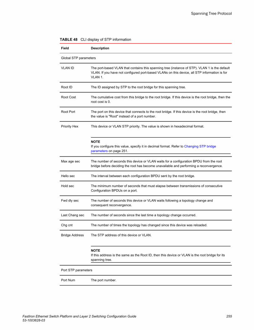
CLI display of STP information TABLE 48
Field Description
Global STP parameters
VLAN ID The port-based VLAN that contains this spanning tree (instance of STP). VLAN 1 is the defaultVLAN. If you have not configured port-based VLANs on this device, all STP information is forVLAN 1.
Root ID The ID assigned by STP to the root bridge for this spanning tree.
Root Cost The cumulative cost from this bridge to the root bridge. If this device is the root bridge, then theroot cost is 0.
Root Port The port on this device that connects to the root bridge. If this device is the root bridge, thenthe value is "Root" instead of a port number.
Priority Hex This device or VLAN STP priority. The value is shown in hexadecimal format.
NOTEIf you configure this value, specify it in decimal format. Refer to Changing STP bridgeparameters on page 251.
Max age sec The number of seconds this device or VLAN waits for a configuration BPDU from the rootbridge before deciding the root has become unavailable and performing a reconvergence.
Hello sec The interval between each configuration BPDU sent by the root bridge.
Hold sec The minimum number of seconds that must elapse between transmissions of consecutiveConfiguration BPDUs on a port.
Fwd dly sec The number of seconds this device or VLAN waits following a topology change andconsequent reconvergence.
Last Chang sec The number of seconds since the last time a topology change occurred.
Chg cnt The number of times the topology has changed since this device was reloaded.
Bridge Address The STP address of this device or VLAN.
NOTEIf this address is the same as the Root ID, then this device or VLAN is the root bridge for itsspanning tree.
Port STP parameters
Port Num The port number.
Spanning Tree Protocol
FastIron Ethernet Switch Platform and Layer 2 Switching Configuration Guide 25553-1003628-03
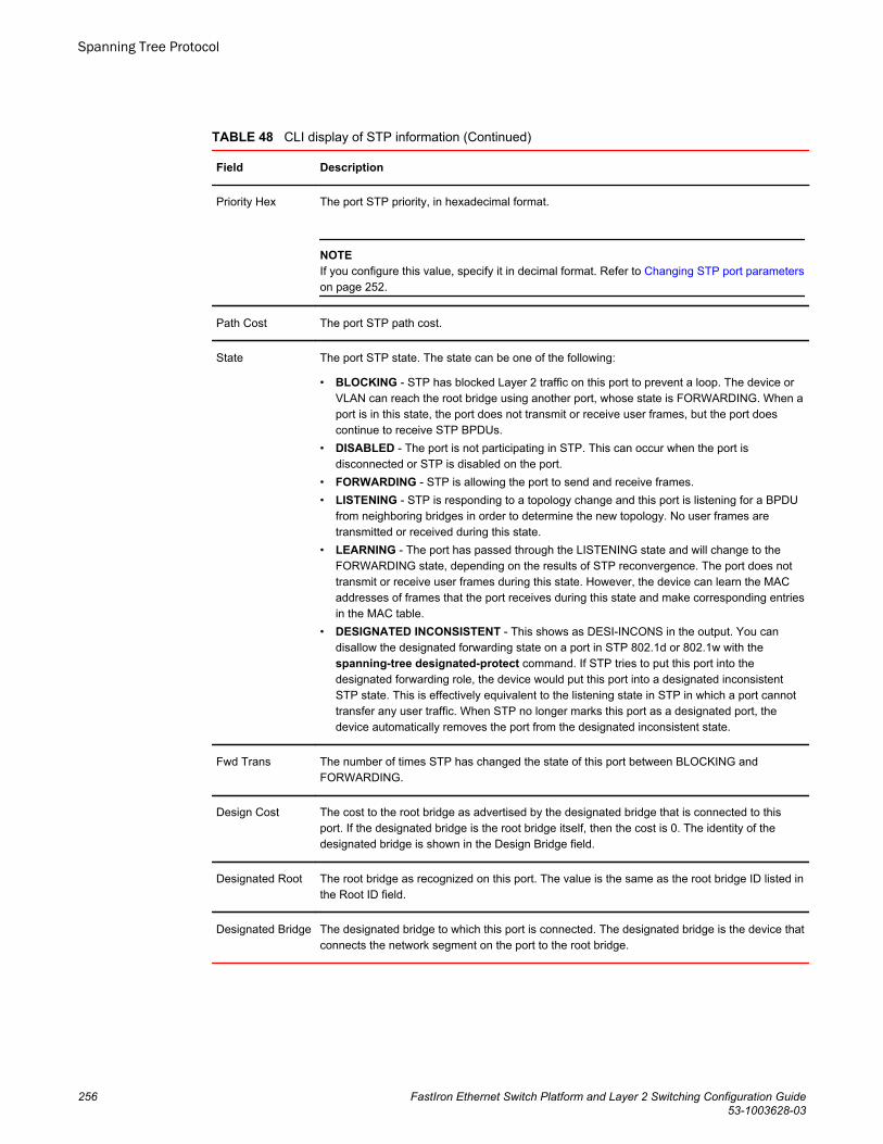
CLI display of STP information (Continued)TABLE 48
Field Description
Priority Hex The port STP priority, in hexadecimal format.
NOTEIf you configure this value, specify it in decimal format. Refer to Changing STP port parameterson page 252.
Path Cost The port STP path cost.
State The port STP state. The state can be one of the following:
• BLOCKING - STP has blocked Layer 2 traffic on this port to prevent a loop. The device orVLAN can reach the root bridge using another port, whose state is FORWARDING. When aport is in this state, the port does not transmit or receive user frames, but the port doescontinue to receive STP BPDUs.
• DISABLED - The port is not participating in STP. This can occur when the port isdisconnected or STP is disabled on the port.
• FORWARDING - STP is allowing the port to send and receive frames.• LISTENING - STP is responding to a topology change and this port is listening for a BPDU
from neighboring bridges in order to determine the new topology. No user frames aretransmitted or received during this state.
• LEARNING - The port has passed through the LISTENING state and will change to theFORWARDING state, depending on the results of STP reconvergence. The port does nottransmit or receive user frames during this state. However, the device can learn the MACaddresses of frames that the port receives during this state and make corresponding entriesin the MAC table.
• DESIGNATED INCONSISTENT - This shows as DESI-INCONS in the output. You candisallow the designated forwarding state on a port in STP 802.1d or 802.1w with thespanning-tree designated-protect command. If STP tries to put this port into thedesignated forwarding role, the device would put this port into a designated inconsistentSTP state. This is effectively equivalent to the listening state in STP in which a port cannottransfer any user traffic. When STP no longer marks this port as a designated port, thedevice automatically removes the port from the designated inconsistent state.
Fwd Trans The number of times STP has changed the state of this port between BLOCKING andFORWARDING.
Design Cost The cost to the root bridge as advertised by the designated bridge that is connected to thisport. If the designated bridge is the root bridge itself, then the cost is 0. The identity of thedesignated bridge is shown in the Design Bridge field.
Designated Root The root bridge as recognized on this port. The value is the same as the root bridge ID listed inthe Root ID field.
Designated Bridge The designated bridge to which this port is connected. The designated bridge is the device thatconnects the network segment on the port to the root bridge.
Spanning Tree Protocol
256 FastIron Ethernet Switch Platform and Layer 2 Switching Configuration Guide53-1003628-03
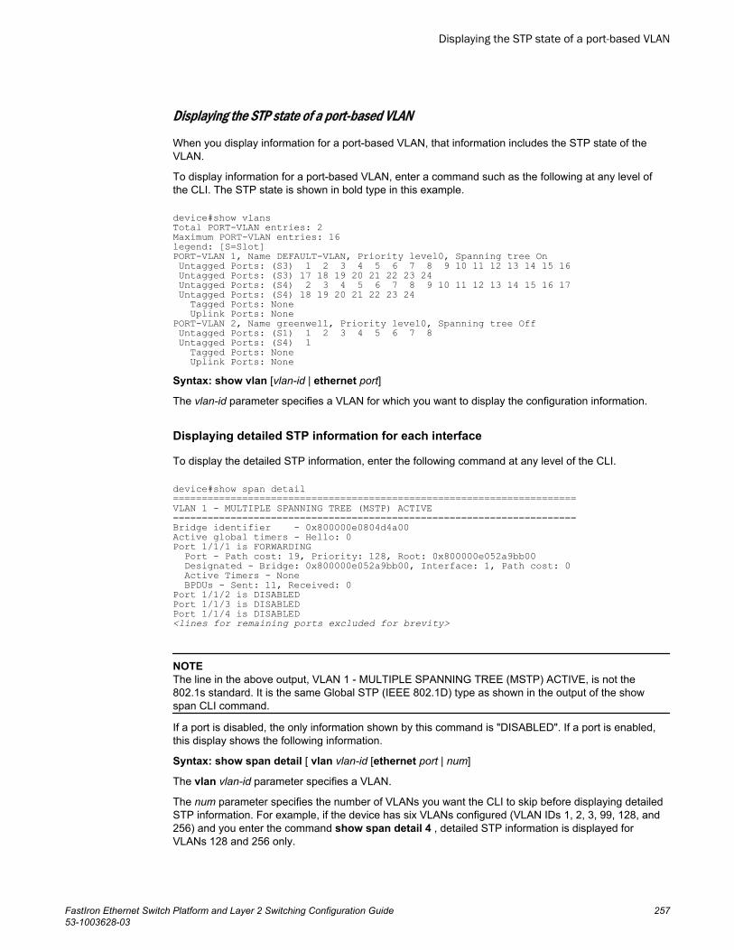
Displaying the STP state of a port-based VLAN
When you display information for a port-based VLAN, that information includes the STP state of theVLAN.
To display information for a port-based VLAN, enter a command such as the following at any level ofthe CLI. The STP state is shown in bold type in this example.
device#show vlansTotal PORT-VLAN entries: 2Maximum PORT-VLAN entries: 16legend: [S=Slot]PORT-VLAN 1, Name DEFAULT-VLAN, Priority level0, Spanning tree On Untagged Ports: (S3) 1 2 3 4 5 6 7 8 9 10 11 12 13 14 15 16 Untagged Ports: (S3) 17 18 19 20 21 22 23 24 Untagged Ports: (S4) 2 3 4 5 6 7 8 9 10 11 12 13 14 15 16 17 Untagged Ports: (S4) 18 19 20 21 22 23 24 Tagged Ports: None Uplink Ports: NonePORT-VLAN 2, Name greenwell, Priority level0, Spanning tree Off Untagged Ports: (S1) 1 2 3 4 5 6 7 8 Untagged Ports: (S4) 1 Tagged Ports: None Uplink Ports: NoneSyntax: show vlan [vlan-id | ethernet port]
The vlan-id parameter specifies a VLAN for which you want to display the configuration information.
Displaying detailed STP information for each interface
To display the detailed STP information, enter the following command at any level of the CLI.
device#show span detail======================================================================VLAN 1 - MULTIPLE SPANNING TREE (MSTP) ACTIVE======================================================================Bridge identifier - 0x800000e0804d4a00Active global timers - Hello: 0Port 1/1/1 is FORWARDING Port - Path cost: 19, Priority: 128, Root: 0x800000e052a9bb00 Designated - Bridge: 0x800000e052a9bb00, Interface: 1, Path cost: 0 Active Timers - None BPDUs - Sent: 11, Received: 0Port 1/1/2 is DISABLEDPort 1/1/3 is DISABLEDPort 1/1/4 is DISABLED<lines for remaining ports excluded for brevity>
NOTEThe line in the above output, VLAN 1 - MULTIPLE SPANNING TREE (MSTP) ACTIVE, is not the802.1s standard. It is the same Global STP (IEEE 802.1D) type as shown in the output of the showspan CLI command.
If a port is disabled, the only information shown by this command is "DISABLED". If a port is enabled,this display shows the following information.
Syntax: show span detail [ vlan vlan-id [ethernet port | num]
The vlan vlan-id parameter specifies a VLAN.
The num parameter specifies the number of VLANs you want the CLI to skip before displaying detailedSTP information. For example, if the device has six VLANs configured (VLAN IDs 1, 2, 3, 99, 128, and256) and you enter the command show span detail 4 , detailed STP information is displayed forVLANs 128 and 256 only.
Displaying the STP state of a port-based VLAN
FastIron Ethernet Switch Platform and Layer 2 Switching Configuration Guide 25753-1003628-03
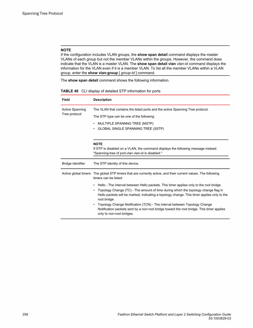
NOTEIf the configuration includes VLAN groups, the show span detail command displays the masterVLANs of each group but not the member VLANs within the groups. However, the command doesindicate that the VLAN is a master VLAN. The show span detail vlan vlan-id command displays theinformation for the VLAN even if it is a member VLAN. To list all the member VLANs within a VLANgroup, enter the show vlan-group [ group-id ] command.
The show span detail command shows the following information.
CLI display of detailed STP information for ports TABLE 49
Field Description
Active SpanningTree protocol
The VLAN that contains the listed ports and the active Spanning Tree protocol.
The STP type can be one of the following:
• MULTIPLE SPANNNG TREE (MSTP)• GLOBAL SINGLE SPANNING TREE (SSTP)
NOTEIf STP is disabled on a VLAN, the command displays the following message instead:"Spanning-tree of port-vlan vlan-id is disabled."
Bridge identifier The STP identity of this device.
Active global timers The global STP timers that are currently active, and their current values. The followingtimers can be listed:
• Hello - The interval between Hello packets. This timer applies only to the root bridge.• Topology Change (TC) - The amount of time during which the topology change flag in
Hello packets will be marked, indicating a topology change. This timer applies only to theroot bridge.
• Topology Change Notification (TCN) - The interval between Topology ChangeNotification packets sent by a non-root bridge toward the root bridge. This timer appliesonly to non-root bridges.
Spanning Tree Protocol
258 FastIron Ethernet Switch Platform and Layer 2 Switching Configuration Guide53-1003628-03
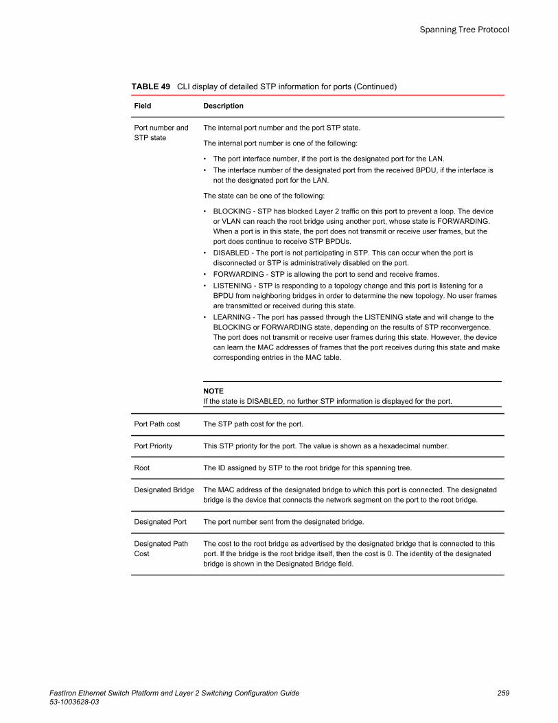
CLI display of detailed STP information for ports (Continued)TABLE 49
Field Description
Port number andSTP state
The internal port number and the port STP state.
The internal port number is one of the following:
• The port interface number, if the port is the designated port for the LAN.• The interface number of the designated port from the received BPDU, if the interface is
not the designated port for the LAN.
The state can be one of the following:
• BLOCKING - STP has blocked Layer 2 traffic on this port to prevent a loop. The deviceor VLAN can reach the root bridge using another port, whose state is FORWARDING.When a port is in this state, the port does not transmit or receive user frames, but theport does continue to receive STP BPDUs.
• DISABLED - The port is not participating in STP. This can occur when the port isdisconnected or STP is administratively disabled on the port.
• FORWARDING - STP is allowing the port to send and receive frames.• LISTENING - STP is responding to a topology change and this port is listening for a
BPDU from neighboring bridges in order to determine the new topology. No user framesare transmitted or received during this state.
• LEARNING - The port has passed through the LISTENING state and will change to theBLOCKING or FORWARDING state, depending on the results of STP reconvergence.The port does not transmit or receive user frames during this state. However, the devicecan learn the MAC addresses of frames that the port receives during this state and makecorresponding entries in the MAC table.
NOTEIf the state is DISABLED, no further STP information is displayed for the port.
Port Path cost The STP path cost for the port.
Port Priority This STP priority for the port. The value is shown as a hexadecimal number.
Root The ID assigned by STP to the root bridge for this spanning tree.
Designated Bridge The MAC address of the designated bridge to which this port is connected. The designatedbridge is the device that connects the network segment on the port to the root bridge.
Designated Port The port number sent from the designated bridge.
Designated PathCost
The cost to the root bridge as advertised by the designated bridge that is connected to thisport. If the bridge is the root bridge itself, then the cost is 0. The identity of the designatedbridge is shown in the Designated Bridge field.
Spanning Tree Protocol
FastIron Ethernet Switch Platform and Layer 2 Switching Configuration Guide 25953-1003628-03
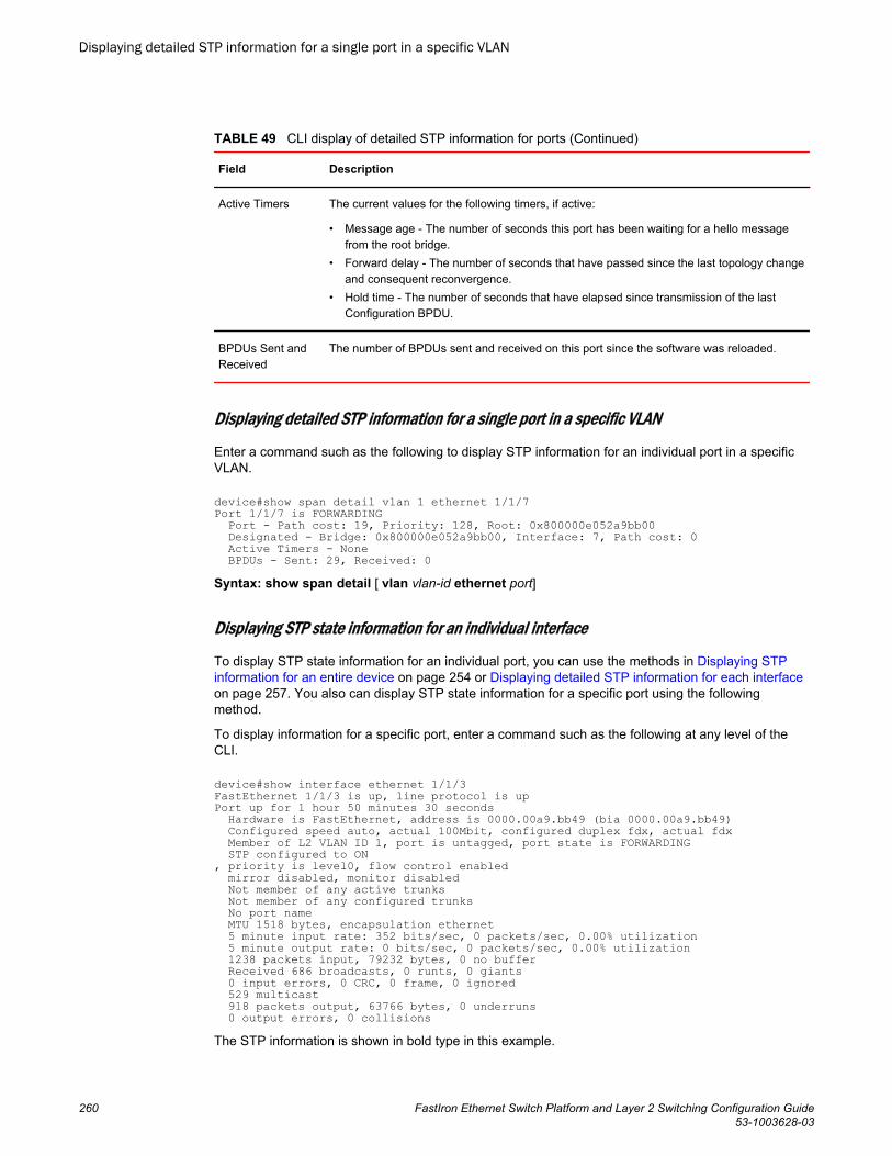
CLI display of detailed STP information for ports (Continued)TABLE 49
Field Description
Active Timers The current values for the following timers, if active:
• Message age - The number of seconds this port has been waiting for a hello messagefrom the root bridge.
• Forward delay - The number of seconds that have passed since the last topology changeand consequent reconvergence.
• Hold time - The number of seconds that have elapsed since transmission of the lastConfiguration BPDU.
BPDUs Sent andReceived
The number of BPDUs sent and received on this port since the software was reloaded.
Displaying detailed STP information for a single port in a specific VLAN
Enter a command such as the following to display STP information for an individual port in a specificVLAN.
device#show span detail vlan 1 ethernet 1/1/7Port 1/1/7 is FORWARDING Port - Path cost: 19, Priority: 128, Root: 0x800000e052a9bb00 Designated - Bridge: 0x800000e052a9bb00, Interface: 7, Path cost: 0 Active Timers - None BPDUs - Sent: 29, Received: 0Syntax: show span detail [ vlan vlan-id ethernet port]
Displaying STP state information for an individual interface
To display STP state information for an individual port, you can use the methods in Displaying STPinformation for an entire device on page 254 or Displaying detailed STP information for each interfaceon page 257. You also can display STP state information for a specific port using the followingmethod.
To display information for a specific port, enter a command such as the following at any level of theCLI.
device#show interface ethernet 1/1/3FastEthernet 1/1/3 is up, line protocol is upPort up for 1 hour 50 minutes 30 seconds Hardware is FastEthernet, address is 0000.00a9.bb49 (bia 0000.00a9.bb49) Configured speed auto, actual 100Mbit, configured duplex fdx, actual fdx Member of L2 VLAN ID 1, port is untagged, port state is FORWARDING STP configured to ON, priority is level0, flow control enabled mirror disabled, monitor disabled Not member of any active trunks Not member of any configured trunks No port name MTU 1518 bytes, encapsulation ethernet 5 minute input rate: 352 bits/sec, 0 packets/sec, 0.00% utilization 5 minute output rate: 0 bits/sec, 0 packets/sec, 0.00% utilization 1238 packets input, 79232 bytes, 0 no buffer Received 686 broadcasts, 0 runts, 0 giants 0 input errors, 0 CRC, 0 frame, 0 ignored 529 multicast 918 packets output, 63766 bytes, 0 underruns 0 output errors, 0 collisionsThe STP information is shown in bold type in this example.
Displaying detailed STP information for a single port in a specific VLAN
260 FastIron Ethernet Switch Platform and Layer 2 Switching Configuration Guide53-1003628-03
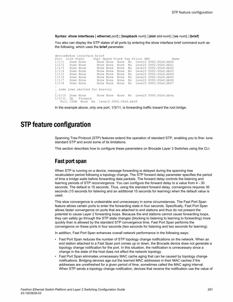
Syntax: show interfaces [ ethernet port] | [loopback num] | [slot slot-num] | [ve num] | [brief]
You also can display the STP states of all ports by entering the show interface brief command such asthe following, which uses the brief parameter.
device#show interface briefPort Link State Dupl Speed Trunk Tag Priori MAC Name1/1/1 Down None None None None No level0 0000.00a9.bb001/1/2 Down None None None None No level0 0000.00a9.bb011/1/3 Down None None None None No level0 0000.00a9.bb021/1/4 Down None None None None No level0 0000.00a9.bb031/1/5 Down None None None None No level0 0000.00a9.bb041/1/6 Down None None None None No level0 0000.00a9.bb051/1/7 Down None None None None No level0 0000.00a9.bb061/1/8 Down None None None None No level0 0000.00a9.bb07.. some rows omitted for brevity.1/3/10 Down None None None None No level0 0000.00a9.bb4a1/3/11 Up Forward Full 100M None No level0 0000.00a9.bb49In the example above, only one port, 1/3/11, is forwarding traffic toward the root bridge.
STP feature configurationSpanning Tree Protocol (STP) features extend the operation of standard STP, enabling you to fine- tunestandard STP and avoid some of its limitations.
This section describes how to configure these parameters on Brocade Layer 3 Switches using the CLI.
Fast port spanWhen STP is running on a device, message forwarding is delayed during the spanning treerecalculation period following a topology change. The STP forward delay parameter specifies the periodof time a bridge waits before forwarding data packets. The forward delay controls the listening andlearning periods of STP reconvergence. You can configure the forward delay to a value from 4 - 30seconds. The default is 15 seconds. Thus, using the standard forward delay, convergence requires 30seconds (15 seconds for listening and an additional 15 seconds for learning) when the default value isused.
This slow convergence is undesirable and unnecessary in some circumstances. The Fast Port Spanfeature allows certain ports to enter the forwarding state in four seconds. Specifically, Fast Port Spanallows faster convergence on ports that are attached to end stations and thus do not present thepotential to cause Layer 2 forwarding loops. Because the end stations cannot cause forwarding loops,they can safely go through the STP state changes (blocking to listening to learning to forwarding) morequickly than is allowed by the standard STP convergence time. Fast Port Span performs theconvergence on these ports in four seconds (two seconds for listening and two seconds for learning).
In addition, Fast Port Span enhances overall network performance in the following ways:
• Fast Port Span reduces the number of STP topology change notifications on the network. When anend station attached to a Fast Span port comes up or down, the Brocade device does not generate atopology change notification for the port. In this situation, the notification is unnecessary since achange in the state of the host does not affect the network topology.
• Fast Port Span eliminates unnecessary MAC cache aging that can be caused by topology changenotifications. Bridging devices age out the learned MAC addresses in their MAC caches if theaddresses are unrefreshed for a given period of time, sometimes called the MAC aging interval.When STP sends a topology change notification, devices that receive the notification use the value of
STP feature configuration
FastIron Ethernet Switch Platform and Layer 2 Switching Configuration Guide 26153-1003628-03
the STP forward delay to quickly age out their MAC caches. For example, if a device normal MACaging interval is 5 minutes, the aging interval changes temporarily to the value of the forward delay(for example, 15 seconds) in response to an STP topology change.
In normal STP, the accelerated cache aging occurs even when a single host goes up or down.Because Fast Port Span does not send a topology change notification when a host on a Fast PortSpan port goes up or down, the unnecessary cache aging that can occur in these circumstancesunder normal STP is eliminated.
Fast Port Span is a system-wide parameter and is enabled by default. Thus, when you boot a device,all the ports that are attached only to end stations run Fast Port Span. For ports that are not eligible forFast Port Span, such as ports connected to other networking devices, the device automatically usesthe normal STP settings. If a port matches any of the following criteria, the port is ineligible for FastPort Span and uses normal STP instead:
• The port is 802.1Q tagged• The port is a member of a trunk group• The port has learned more than one active MAC address• An STP Configuration BPDU has been received on the port, thus indicating the presence of another
bridge on the port.
You also can explicitly exclude individual ports from Fast Port Span if needed. For example, if the onlyuplink ports for a wiring closet switch are Gbps ports, you can exclude the ports from Fast Port Span.
Disabling and re-enabling fast port span
Fast Port Span is a system-wide parameter and is enabled by default. Therefore, all ports that areeligible for Fast Port Span use it.
To disable or re-enable Fast Port Span, enter the following commands.
device(config)#no fast port-spandevice(config)#write memorySyntax: [no] fast port-span
NOTEThe fast port-span command has additional parameters that let you exclude specific ports. Theseparameters are shown in the following section.
To re-enable Fast Port Span, enter the following commands.
device(config)#fast port-spandevice(config)#write memory
Excluding specific ports from fast port span
To exclude a port from Fast Port Span while leaving Fast Port Span enabled globally, entercommands such as the following.
device(config)#fast port-span exclude ethernet 1device(config)#write memory To exclude a set of ports from Fast Port Span, enter commands such as the following.
device(config)#fast port-span exclude ethernet 1 ethernet 2 ethernet 3device(config)#write memory
Disabling and re-enabling fast port span
262 FastIron Ethernet Switch Platform and Layer 2 Switching Configuration Guide53-1003628-03
To exclude a contiguous (unbroken) range of ports from Fast Span, enter commands such as thefollowing.
device(config)#fast port-span exclude ethernet 1 to 24device(config)#write memory Syntax: [no] fast port-span [ exclude ethernet port [ethernet port] | to [port]]
To re-enable Fast Port Span on a port, enter a command such as the following.
device(config)#no fast port-span exclude ethernet 1 device(config)#write memory This command re-enables Fast Port Span on port 1 only and does not re-enable Fast Port Span onother excluded ports. You also can re-enable Fast Port Span on a list or range of ports using the syntaxshown above this example.
To re-enable Fast Port Span on all excluded ports, disable and then re-enable Fast Port Span byentering the following commands.
device(config)#no fast port-span device(config)#fast port-spandevice(config)#write memory Disabling and then re-enabling Fast Port Span clears the exclude settings and thus enables Fast PortSpan on all eligible ports. To make sure Fast Port Span remains enabled on the ports following asystem reset, save the configuration changes to the startup-config file after you re-enable Fast PortSpan. Otherwise, when the system resets, those ports will again be excluded from Fast Port Span.
Fast Uplink SpanThe Fast Port Span feature described in the previous section enhances STP performance for endstations. The Fast Uplink Span feature enhances STP performance for wiring closet switches withredundant uplinks. Using the default value for the standard STP forward delay, convergence following atransition from an active link to a redundant link can take 30 seconds (15 seconds for listening and anadditional 15 seconds for learning).
You can use the Fast Uplink Span feature on a Brocade device deployed as a wiring closet switch todecrease the convergence time for the uplink ports to another device to just one second. The newUplink port directly goes to forward mode (bypassing listening and learning modes). The wiring closetswitch must be a Brocade device but the device at the other end of the link can be a Brocade device oranother vendor’s switch.
Configuration of the Fast Uplink Span feature takes place entirely on the Brocade device. To configurethe Fast Uplink Span feature, specify a group of ports that have redundant uplinks on the wiring closetswitch (Brocade device). If the active link becomes unavailable, the Fast Uplink Span feature transitionsthe forwarding to one of the other redundant uplink ports in just one second. All Fast Uplink Span-enabled ports are members of a single Fast Uplink Span group.
NOTETo avoid the potential for temporary bridging loops, Brocade recommends that you use the Fast Uplinkfeature only for wiring closet switches (switches at the edge of the network cloud). In addition, enablethe feature only on a group of ports intended for redundancy, so that at any given time only one of theports is expected to be in the forwarding state.
Fast Uplink Span
FastIron Ethernet Switch Platform and Layer 2 Switching Configuration Guide 26353-1003628-03
NOTEWhen the wiring closet switch (Brocade device) first comes up or when STP is first enabled, the uplinkports still must go through the standard STP state transition without any acceleration. This behaviorguards against temporary routing loops as the switch tries to determine the states for all the ports.Fast Uplink Span acceleration applies only when a working uplink becomes unavailable.
Active uplink port failure
The active uplink port is the port elected as the root port using the standard STP rules. All other portsin the group are redundant uplink ports. If an active uplink port becomes unavailable, Fast Uplink Spantransitions the forwarding of traffic to one of the redundant ports in the Fast Uplink Span group in onesecond bypassing listening and learning port states.
Switchover to the active uplink port
When a failed active uplink port becomes available again, switchover from the redundant port to theactive uplink port is delayed by 30 seconds. The delay allows the remote port to transition toforwarding mode using the standard STP rules. After 30 seconds, the blocked active uplink port beginsforwarding in just one second and the redundant port is blocked.
NOTEUse caution when changing the spanning tree priority. If the switch becomes the root bridge, FastUplink Span will be disabled automatically.
Fast Uplink Span Rules for Trunk Groups
If you add a port to a Fast Uplink Span group that is a member of a trunk group, the following rulesapply:
• If you add the primary port of a trunk group to the Fast Uplink Span group, all other ports in thetrunk group are automatically included in the group. Similarly, if you remove the primary port in atrunk group from the Fast Uplink Span group, the other ports in the trunk group are automaticallyremoved from the Fast Uplink Span group.
• You cannot add a subset of the ports in a trunk group to the Fast Uplink Span group. All ports in atrunk group have the same Fast Uplink Span property, as they do for other port properties.
• If the working trunk group is partially down but not completely down, no switch-over to the backupoccurs. This behavior is the same as in the standard STP feature.
• If the working trunk group is completely down, a backup trunk group can go through an acceleratedtransition only if the following are true:
‐ The trunk group is included in the fast uplink group.‐ All other ports except those in this trunk group are either disabled or blocked. The accelerated
transition applies to all ports in this trunk group.
When the original working trunk group comes back (partially or fully), the transition back to the originaltopology is accelerated if the conditions listed above are met.
Active uplink port failure
264 FastIron Ethernet Switch Platform and Layer 2 Switching Configuration Guide53-1003628-03
Configuring a Fast Uplink Port Group
To configure a group of ports for Fast Uplink Span, enter the following commands:
device(config)# fast uplink-span ethernet 1/1/1 to 1/1/4device(config)# write memorySyntax: [no] fast uplink-span [ ethernet port [ethernet port...| to port]]
This example configures four ports, 1/1/1 - 1/1/4, as a Fast Uplink Span group. In this example, all fourports are connected to a wiring closet switch. Only one of the links is expected to be active at any time.The other links are redundant. For example, if the link on port 1/1/4 is the active link on the wiring closetswitch but becomes unavailable, one of the other links takes over. Because the ports are configured ina Fast Uplink Span group, the STP convergence takes one second instead of taking at least 30seconds using the standard STP forward delay.
You can add ports to a Fast Uplink Span group by entering the fast uplink-span command additionaltimes with additional ports. The device can have only one Fast Uplink Span group, so all the ports youidentify as Fast Uplink Span ports are members of the same group.
To remove a Fast Uplink Span group or to remove individual ports from a group, use "no" in front of theappropriate fast uplink-span command. For example, to remove ports 4/1/3 and 4/1/4 from the FastUplink Span group configured above, enter the following commands:
device(config)# no fast uplink-span ethernet 1/1/1 to 1/1/4device(config)# write memoryTo check the status of ports with Fast Uplink Span enabled.
device(config)# show span fast-uplink-spanSTP instance owned by VLAN 1Global STP (IEEE 802.1D) Parameters:VLAN Root Root Root Prio Max He- Ho- Fwd Last Chg Bridge ID ID Cost Port rity Age llo ld dly Chang cnt Address Hex sec sec sec sec sec 1 000000c100000001 2 1/3/1 8000 20 2 1 15 65 15 000011111111Port STP Parameters:Port Prio Path State Fwd Design Designated Designated Num rity Cost Trans Cost Root Bridge Hex 1/1/2 80 0 DISABLED 0 0 0000000000000000 0000000000000000 1/1/3 80 0 DISABLED 0 0 0000000000000000 0000000000000000 1/1/4 80 4 FORWARDING 1 2 000000c100000001 8000000011111111 1/1/5 80 0 DISABLED 0 0 0000000000000000 0000000000000000 1/1/6 80 0 DISABLED 0 0 0000000000000000 0000000000000000 1/1/7 80 0 DISABLED 0 0 0000000000000000 0000000000000000 1/1/8 80 0 DISABLED 0 0 0000000000000000 0000000000000000 1/1/9 80 0 DISABLED 0 0 0000000000000000 0000000000000000 Syntax: show span fast-uplink-span
Configuring Fast Uplink Span within a VLAN
You can also configure Fast Uplink Span on the interfaces within a VLAN.
To configure Fast Uplink Span for a VLAN, enter command such as the following.
device(config)#vlan 10device(config-vlan-10)#untag ethernet 1/1/1 to 1/1/3device(config-vlan-10)#fast uplink-span ethernet 1/1/1 to 1/1/3Syntax:[no] fast uplink-span ethernet port-no
To check the status of Fast Uplink Span for a specified VLAN.
device(config-vlan-2)#show span vlan 2 fast-uplink-span
Configuring a Fast Uplink Port Group
FastIron Ethernet Switch Platform and Layer 2 Switching Configuration Guide 26553-1003628-03
STP instance owned by VLAN 2Global STP (IEEE 802.1D) Parameters:VLAN Root Root Root Prio Max He- Ho- Fwd Last Chg Bridge ID ID Cost Port rity Age llo ld dly Chang cnt Address Hex sec sec sec sec sec 2 8000000011111111 0 Root 8000 20 2 1 15 29596 0 000011111111Port STP Parameters:Port Prio Path State Fwd Design Designated Designated Num rity Cost Trans Cost Root Bridge Hex 1/1/1 80 4 LISTENING 0 0 8000000011111111 8000000011111111 Syntax: show span vlan vlan-id fast-uplink-span
The VLAN vlan-id parameter displays Fast Uplink Span information for the specified VLAN.
802.1W Rapid Spanning Tree (RSTP)Earlier implementation by Brocade of Rapid Spanning Tree Protocol (RSTP), which was 802.1W Draft3, provided only a subset of the IEEE 802.1W standard; whereas the 802.1W RSTP feature providesthe full standard. The implementation of the 802.1W Draft 3 is referred to as RSTP Draft 3.
RSTP Draft3 will continue to be supported on Brocade devices for backward compatibility. However,customers who are currently using RSTP Draft 3 should migrate to 802.1W.
The 802.1W feature provides rapid traffic reconvergence for point-to-point links within a fewmilliseconds (0 - 500 milliseconds), following the failure of a bridge or bridge port. This reconvergenceoccurs more rapidly than the reconvergence provided by the 802.1D Spanning Tree Protocol (STP)) orby RSTP Draft 3.
NOTEThis rapid convergence will not occur on ports connected to shared media devices, such as hubs. Totake advantage of the rapid convergence provided by 802.1W, make sure to explicitly configure allpoint-to-point links in a topology.
The convergence provided by the standard 802.1W protocol occurs more rapidly than theconvergence provided by previous spanning tree protocols because of the following:
• Classic or legacy 802.1D STP protocol requires a newly selected Root port to go through listeningand learning stages before traffic convergence can be achieved. The 802.1D traffic convergencetime is calculated using the following formula.
2 x FORWARD_DELAY + BRIDGE_MAX_AGE.
If default values are used in the parameter configuration, convergence can take up to 50 seconds. (Inthis document STP will be referred to as 802.1D.)
• RSTP Draft 3 works only on bridges that have Alternate ports, which are the precalculated "nextbest root port". (Alternate ports provide back up paths to the root bridge.) Although convergenceoccurs from 0 - 500 milliseconds in RSTP Draft 3, the spanning tree topology reverts to the 802.1Dconvergence if an Alternate port is not found.
• Convergence in 802.1w bridge is not based on any timer values. Rather, it is based on the explicithandshakes between Designated ports and their connected Root ports to achieve convergence inless than 500 milliseconds.
Bridges and bridge port roles
A bridge in an 802.1W rapid spanning tree topology is assigned as the root bridge if it has the highestpriority (lowest bridge identifier) in the topology. Other bridges are referred to as non-root bridges.
802.1W Rapid Spanning Tree (RSTP)
266 FastIron Ethernet Switch Platform and Layer 2 Switching Configuration Guide53-1003628-03
Unique roles are assigned to ports on the root and non-root bridges. Role assignments are based onthe following information contained in the Rapid Spanning Tree Bridge Packet Data Unit (RST BPDU):
• Root bridge ID• Path cost value• Transmitting bridge ID• Designated port ID
The 802.1W algorithm uses this information to determine if the RST BPDU received by a port issuperior to the RST BPDU that the port transmits. The two values are compared in the order as givenabove, starting with the Root bridge ID. The RST BPDU with a lower value is considered superior. Thesuperiority and inferiority of the RST BPDU is used to assign a role to a port.
If the value of the received RST BPDU is the same as that of the transmitted RST BPDU, then the portID in the RST BPDUs are compared. The RST BPDU with the lower port ID is superior. Port roles arethen calculated appropriately.
The port role is included in the BPDU that it transmits. The BPDU transmitted by an 802.1W port isreferred to as an RST BPDU, while it is operating in 802.1W mode.
Ports can have one of the following roles:
• Root - Provides the lowest cost path to the root bridge from a specific bridge• Designated - Provides the lowest cost path to the root bridge from a LAN to which it is connected• Alternate - Provides an alternate path to the root bridge when the root port goes down• Backup - Provides a backup to the LAN when the Designated port goes down• Disabled - Has no role in the topology
Assignment of port roles
At system start-up, all 802.1W-enabled bridge ports assume a Designated role. Once start-up iscomplete, the 802.1W algorithm calculates the superiority or inferiority of the RST BPDU that isreceived and transmitted on a port.
On a root bridge, each port is assigned a Designated port role, except for ports on the same bridge thatare physically connected together. In these type of ports, the port that receives the superior RST BPDUbecomes the Backup port , while the other port becomes the Designated port .
On non-root bridges, ports are assigned as follows:
• The port that receives the RST BPDU with the lowest path cost from the root bridge becomes theRoot port .
• If two ports on the same bridge are physically connected, the port that receives the superior RSTBPDU becomes the Backup port , while the other port becomes the Designated port .
• If a non-root bridge already has a Root port, then the port that receives an RST BPDU that issuperior to those it can transmit becomes the Alternate port .
• If the RST BPDU that a port receives is inferior to the RST BPDUs it transmits, then the portbecomes a Designated port .
• If the port is down or if 802.1W is disabled on the port, that port is given the role of Disabled port .Disabled ports have no role in the topology. However, if 802.1W is enabled on a port with a link downand the link of that port comes up, then that port assumes one of the following port roles: Root,Designated, Alternate, or Backup.
The following example (Figure 39 ) explains role assignments in a simple RSTP topology.
NOTEAll examples in this document assume that all ports in the illustrated topologies are point-to-point linksand are homogeneous (they have the same path cost value) unless otherwise specified.
Spanning Tree Protocol
FastIron Ethernet Switch Platform and Layer 2 Switching Configuration Guide 26753-1003628-03
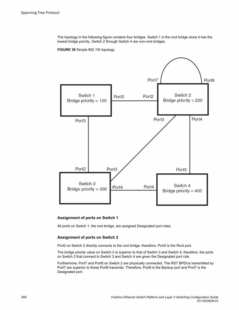
The topology in the following figure contains four bridges. Switch 1 is the root bridge since it has thelowest bridge priority. Switch 2 through Switch 4 are non-root bridges.
FIGURE 39 Simple 802.1W topology
Assignment of ports on Switch 1
All ports on Switch 1, the root bridge, are assigned Designated port roles.
Assignment of ports on Switch 2
Port2 on Switch 2 directly connects to the root bridge; therefore, Port2 is the Root port.
The bridge priority value on Switch 2 is superior to that of Switch 3 and Switch 4; therefore, the portson Switch 2 that connect to Switch 3 and Switch 4 are given the Designated port role.
Furthermore, Port7 and Port8 on Switch 2 are physically connected. The RST BPDUs transmitted byPort7 are superior to those Port8 transmits. Therefore, Port8 is the Backup port and Port7 is theDesignated port.
Spanning Tree Protocol
268 FastIron Ethernet Switch Platform and Layer 2 Switching Configuration Guide53-1003628-03
Assignment of ports on Switch 3
Port2 on Switch 3 directly connects to the Designated port on the root bridge; therefore, it assumes theRoot port role.
The root path cost of the RST BPDUs received on Port4/Switch 3 is inferior to the RST BPDUstransmitted by the port; therefore, Port4/Switch 3 becomes the Designated port.
Similarly Switch 3 has a bridge priority value inferior to Switch 2. Port3 on Switch 3 connects to Port 3on Switch 2. This port will be given the Alternate port role, since a Root port is already established onthis bridge.
Assignment of ports on Switch 4
Switch 4 is not directly connected to the root bridge. It has two ports with superior incoming RSTBPDUs from two separate LANs: Port3 and Port4. The RST BPDUs received on Port3 are superior tothe RST BPDUs received on port 4; therefore, Port3 becomes the Root port and Port4 becomes theAlternate port.
Edge ports and edge port roles
The Brocade implementation of 802.1W allows ports that are configured as Edge ports to be present inan 802.1W topology. (Figure 40 ). Edge ports are ports of a bridge that connect to workstations orcomputers. Edge ports do not register any incoming BPDU activities.
Edge ports assume Designated port roles. Port flapping does not cause any topology change events onEdge ports since 802.1W does not consider Edge ports in the spanning tree calculations.
Edge ports and edge port roles
FastIron Ethernet Switch Platform and Layer 2 Switching Configuration Guide 26953-1003628-03
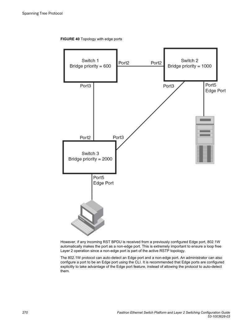
FIGURE 40 Topology with edge ports
However, if any incoming RST BPDU is received from a previously configured Edge port, 802.1Wautomatically makes the port as a non-edge port. This is extremely important to ensure a loop freeLayer 2 operation since a non-edge port is part of the active RSTP topology.
The 802.1W protocol can auto-detect an Edge port and a non-edge port. An administrator can alsoconfigure a port to be an Edge port using the CLI. It is recommended that Edge ports are configuredexplicitly to take advantage of the Edge port feature, instead of allowing the protocol to auto-detectthem.
Spanning Tree Protocol
270 FastIron Ethernet Switch Platform and Layer 2 Switching Configuration Guide53-1003628-03
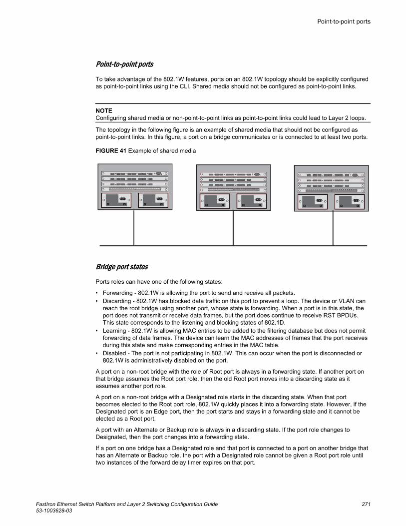
Point-to-point ports
To take advantage of the 802.1W features, ports on an 802.1W topology should be explicitly configuredas point-to-point links using the CLI. Shared media should not be configured as point-to-point links.
NOTEConfiguring shared media or non-point-to-point links as point-to-point links could lead to Layer 2 loops.
The topology in the following figure is an example of shared media that should not be configured aspoint-to-point links. In this figure, a port on a bridge communicates or is connected to at least two ports.
FIGURE 41 Example of shared media
Bridge port states
Ports roles can have one of the following states:
• Forwarding - 802.1W is allowing the port to send and receive all packets.• Discarding - 802.1W has blocked data traffic on this port to prevent a loop. The device or VLAN can
reach the root bridge using another port, whose state is forwarding. When a port is in this state, theport does not transmit or receive data frames, but the port does continue to receive RST BPDUs.This state corresponds to the listening and blocking states of 802.1D.
• Learning - 802.1W is allowing MAC entries to be added to the filtering database but does not permitforwarding of data frames. The device can learn the MAC addresses of frames that the port receivesduring this state and make corresponding entries in the MAC table.
• Disabled - The port is not participating in 802.1W. This can occur when the port is disconnected or802.1W is administratively disabled on the port.
A port on a non-root bridge with the role of Root port is always in a forwarding state. If another port onthat bridge assumes the Root port role, then the old Root port moves into a discarding state as itassumes another port role.
A port on a non-root bridge with a Designated role starts in the discarding state. When that portbecomes elected to the Root port role, 802.1W quickly places it into a forwarding state. However, if theDesignated port is an Edge port, then the port starts and stays in a forwarding state and it cannot beelected as a Root port.
A port with an Alternate or Backup role is always in a discarding state. If the port role changes toDesignated, then the port changes into a forwarding state.
If a port on one bridge has a Designated role and that port is connected to a port on another bridge thathas an Alternate or Backup role, the port with a Designated role cannot be given a Root port role untiltwo instances of the forward delay timer expires on that port.
Point-to-point ports
FastIron Ethernet Switch Platform and Layer 2 Switching Configuration Guide 27153-1003628-03
Edge port and non-edge port states
As soon as a port is configured as an Edge port using the CLI, it goes into a forwarding state instantly(in less than 100 msec).
When the link to a port comes up and 802.1W detects that the port is an Edge port, that port instantlygoes into a forwarding state.
If 802.1W detects that port as a non-edge port, the port state is changed as determined by the result ofprocessing the received RST BPDU. The port state change occurs within four seconds of link up orafter two hello timer expires on the port.
Changes to port roles and states
To achieve convergence in a topology, a port role and state changes as it receives and transmits newRST BPDUs. Changes in a port role and state constitute a topology change. Besides the superiorityand inferiority of the RST BPDU, bridge-wide and per-port state machines are used to determine aport role as well as a port state. Port state machines also determine when port role and state changesoccur.
Port Role Selection state machines
The bridge uses the Port Role Selection state machine to determine if port role changes are requiredon the bridge. This state machine performs a computation when one of the following events occur:
• New information is received on any port on the bridge• The timer expires for the current information on a port on the bridge
Each port uses the following state machines:
• Port Information - This state machine keeps track of spanning-tree information currently used by theport. It records the origin of the information and ages out any information that was derived from anincoming BPDU.
• Port Role Transition - This state machine keeps track of the current port role and transitions the portto the appropriate role when required. It moves the Root port and the Designated port intoforwarding states and moves the Alternate and Backup ports into discarding states.
• Port Transmit - This state machine is responsible for BPDU transmission. It checks to ensure onlythe maximum number of BPDUs per hello interval are sent every second. Based on what mode it isoperating in, it sends out either legacy BPDUs or RST BPDUs. In this document legacy BPDUs arealso referred to as STP BPDUs.
• Port Protocol Migration - This state machine deals with compatibility with 802.1D bridges. When alegacy BPDU is detected on a port, this state machine configures the port to transmit and receivelegacy BPDUs and operate in the legacy mode.
• Topology Change - This state machine detects, generates, and propagates topology changenotifications. It acknowledges Topology Change Notice (TCN) messages when operating in 802.1Dmode. It also flushes the MAC table when a topology change event takes place.
• Port State Transition - This state machine transitions the port to a discarding, learning, or forwardingstate and performs any necessary processing associated with the state changes.
• Port Timers - This state machine is responsible for triggering any of the state machines describedabove, based on expiration of specific port timers.
In contrast to the 802.1D standard, the 802.1W standard does not have any bridge specific timers. Alltimers in the CLI are applied on a per-port basis, even though they are configured under bridgeparameters.
802.1W state machines attempt to quickly place the ports into either a forwarding or discarding state.Root ports are quickly placed in forwarding state when both of the following events occur:
Edge port and non-edge port states
272 FastIron Ethernet Switch Platform and Layer 2 Switching Configuration Guide53-1003628-03
• It is assigned to be the Root port.• It receives an RST BPDU with a proposal flag from a Designated port. The proposal flag is sent by
ports with a Designated role when they are ready to move into a forwarding state.
When a the role of Root port is given to another port, the old Root port is instructed to reroot. The oldRoot port goes into a discarding state and negotiates with its peer port for a new role and a new state. Apeer port is the port on the other bridge to which the port is connected. For example, in Figure 42 ,Port1 of Switch 200 is the peer port of Port2 of Switch 100.
A port with a Designated role is quickly placed into a forwarding state if one of the following occurs:
• The Designated port receives an RST BPDU that contains an agreement flag from a Root port• The Designated port is an Edge port
However, a Designated port that is attached to an Alternate port or a Backup port must wait until theforward delay timer expires twice on that port while it is still in a Designated role, before it can proceedto the forwarding state.
Backup ports are quickly placed into discarding states.
Alternate ports are quickly placed into discarding states.
A port operating in 802.1W mode may enter a learning state to allow MAC entries to be added to thefiltering database; however, this state is transient and lasts only a few milliseconds, if the port isoperating in 802.1W mode and if the port meets the conditions for rapid transition.
Handshake mechanisms
To rapidly transition a Designated or Root port into a forwarding state, the Port Role Transition statemachine uses handshake mechanisms to ensure loop free operations. It uses one type of handshake ifno Root port has been assigned on a bridge, and another type if a Root port has already beenassigned.
Handshake when no root port is elected
If a Root port has not been assigned on a bridge, 802.1W uses the Proposing -> Proposed -> Sync ->Synced -> Agreed handshake:
• Proposing - The Designated port on the root bridge sends an RST BPDU packet to its peer port thatcontains a proposal flag. The proposal flag is a signal that indicates that the Designated port is readyto put itself in a forwarding state (Figure 42 ). The Designated port continues to send this flag in itsRST BPDU until it is placed in a forwarding state (Figure 45 ) or is forced to operate in 802.1D mode.(Refer to Compatibility of 802.1W with 802.1D on page 293).
• Proposed - When a port receives an RST BPDU with a proposal flag from the Designated port on itspoint-to-point link, it asserts the Proposed signal and one of the following occurs (Figure 42 ):
‐ If the RST BPDU that the port receives is superior to what it can transmit, the port assumes therole of a Root port. (Refer to the section on Bridges and bridge port roles on page 266.)
‐ If the RST BPDU that the port receives is inferior to what it can transmit, then the port is given therole of Designated port.
NOTEProposed will never be asserted if the port is connected on a shared media link.
In the following figure, Port3/Switch 200 is elected as the Root port.
Spanning Tree Protocol
FastIron Ethernet Switch Platform and Layer 2 Switching Configuration Guide 27353-1003628-03
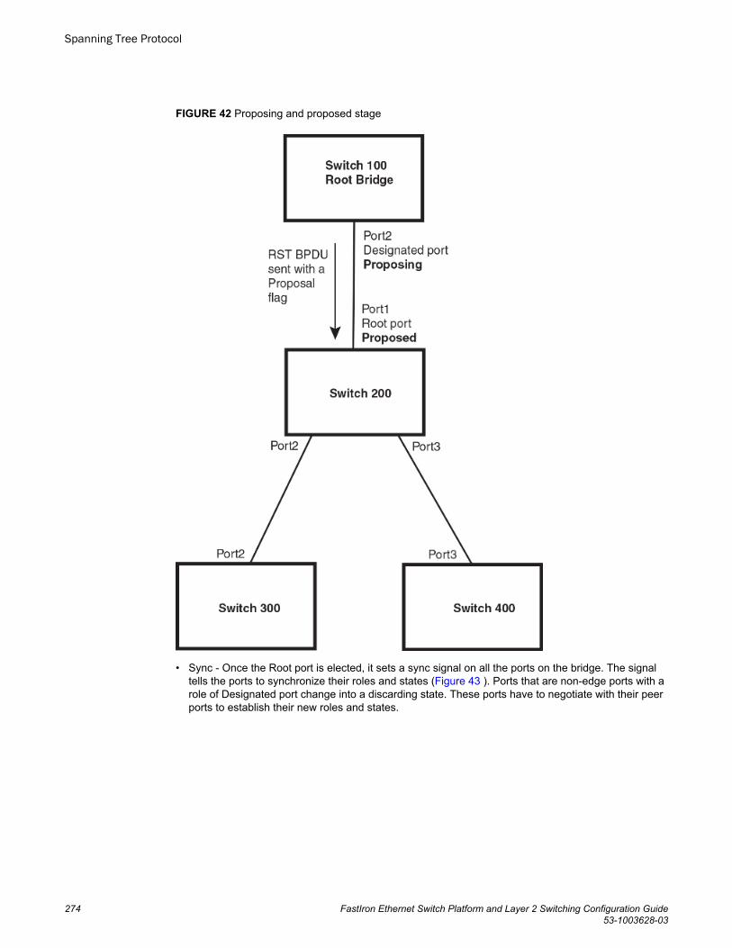
FIGURE 42 Proposing and proposed stage
• Sync - Once the Root port is elected, it sets a sync signal on all the ports on the bridge. The signaltells the ports to synchronize their roles and states (Figure 43 ). Ports that are non-edge ports with arole of Designated port change into a discarding state. These ports have to negotiate with their peerports to establish their new roles and states.
Spanning Tree Protocol
274 FastIron Ethernet Switch Platform and Layer 2 Switching Configuration Guide53-1003628-03
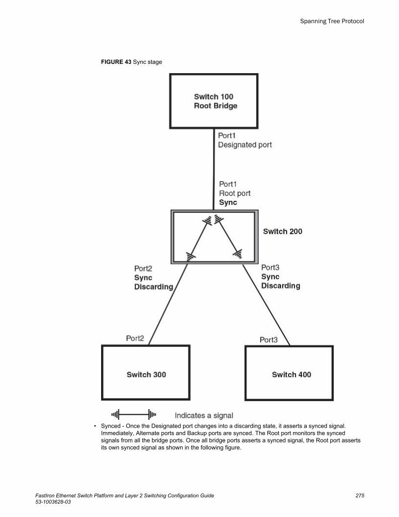
FIGURE 43 Sync stage
• Synced - Once the Designated port changes into a discarding state, it asserts a synced signal.Immediately, Alternate ports and Backup ports are synced. The Root port monitors the syncedsignals from all the bridge ports. Once all bridge ports asserts a synced signal, the Root port assertsits own synced signal as shown in the following figure.
Spanning Tree Protocol
FastIron Ethernet Switch Platform and Layer 2 Switching Configuration Guide 27553-1003628-03
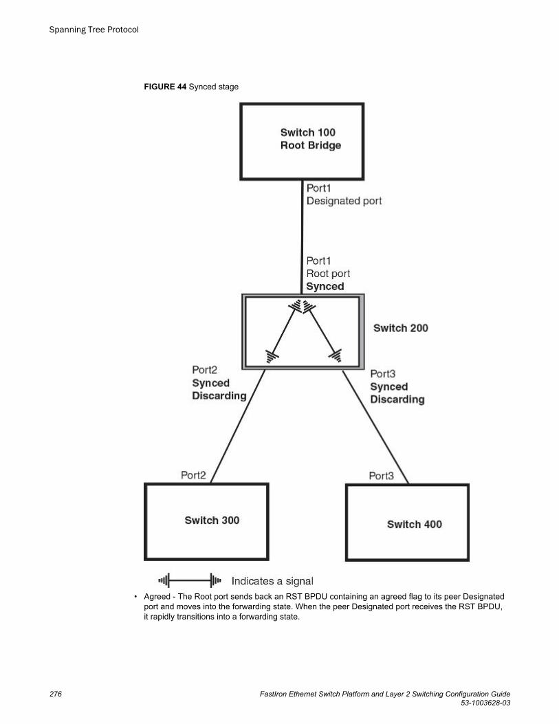
FIGURE 44 Synced stage
• Agreed - The Root port sends back an RST BPDU containing an agreed flag to its peer Designatedport and moves into the forwarding state. When the peer Designated port receives the RST BPDU,it rapidly transitions into a forwarding state.
Spanning Tree Protocol
276 FastIron Ethernet Switch Platform and Layer 2 Switching Configuration Guide53-1003628-03
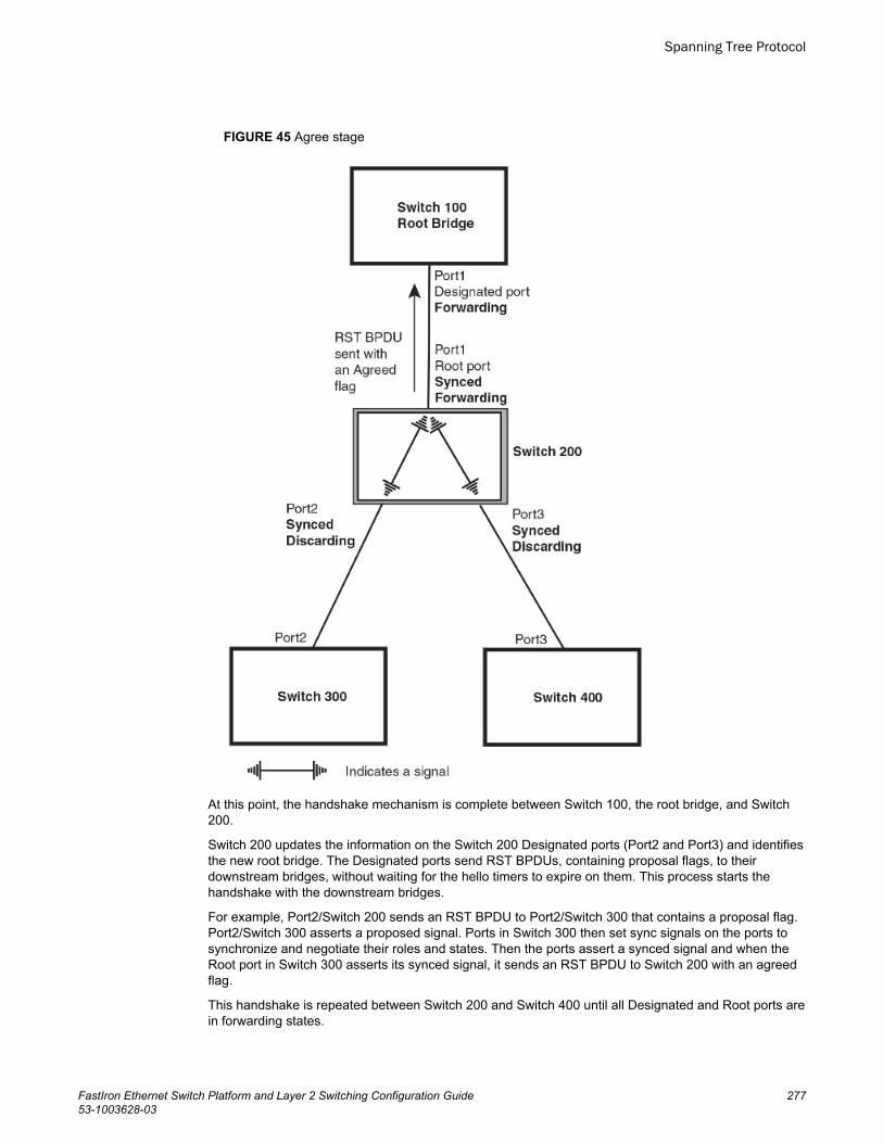
FIGURE 45 Agree stage
At this point, the handshake mechanism is complete between Switch 100, the root bridge, and Switch200.
Switch 200 updates the information on the Switch 200 Designated ports (Port2 and Port3) and identifiesthe new root bridge. The Designated ports send RST BPDUs, containing proposal flags, to theirdownstream bridges, without waiting for the hello timers to expire on them. This process starts thehandshake with the downstream bridges.
For example, Port2/Switch 200 sends an RST BPDU to Port2/Switch 300 that contains a proposal flag.Port2/Switch 300 asserts a proposed signal. Ports in Switch 300 then set sync signals on the ports tosynchronize and negotiate their roles and states. Then the ports assert a synced signal and when theRoot port in Switch 300 asserts its synced signal, it sends an RST BPDU to Switch 200 with an agreedflag.
This handshake is repeated between Switch 200 and Switch 400 until all Designated and Root ports arein forwarding states.
Spanning Tree Protocol
FastIron Ethernet Switch Platform and Layer 2 Switching Configuration Guide 27753-1003628-03
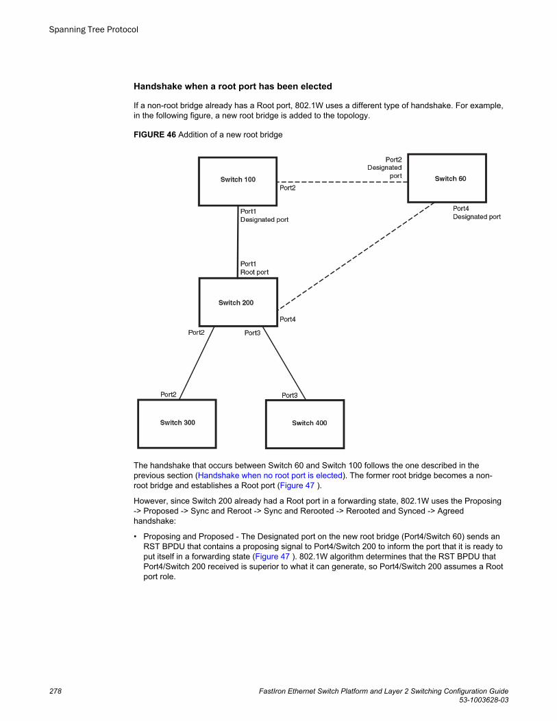
Handshake when a root port has been elected
If a non-root bridge already has a Root port, 802.1W uses a different type of handshake. For example,in the following figure, a new root bridge is added to the topology.
FIGURE 46 Addition of a new root bridge
The handshake that occurs between Switch 60 and Switch 100 follows the one described in theprevious section (Handshake when no root port is elected). The former root bridge becomes a non-root bridge and establishes a Root port (Figure 47 ).
However, since Switch 200 already had a Root port in a forwarding state, 802.1W uses the Proposing-> Proposed -> Sync and Reroot -> Sync and Rerooted -> Rerooted and Synced -> Agreedhandshake:
• Proposing and Proposed - The Designated port on the new root bridge (Port4/Switch 60) sends anRST BPDU that contains a proposing signal to Port4/Switch 200 to inform the port that it is ready toput itself in a forwarding state (Figure 47 ). 802.1W algorithm determines that the RST BPDU thatPort4/Switch 200 received is superior to what it can generate, so Port4/Switch 200 assumes a Rootport role.
Spanning Tree Protocol
278 FastIron Ethernet Switch Platform and Layer 2 Switching Configuration Guide53-1003628-03
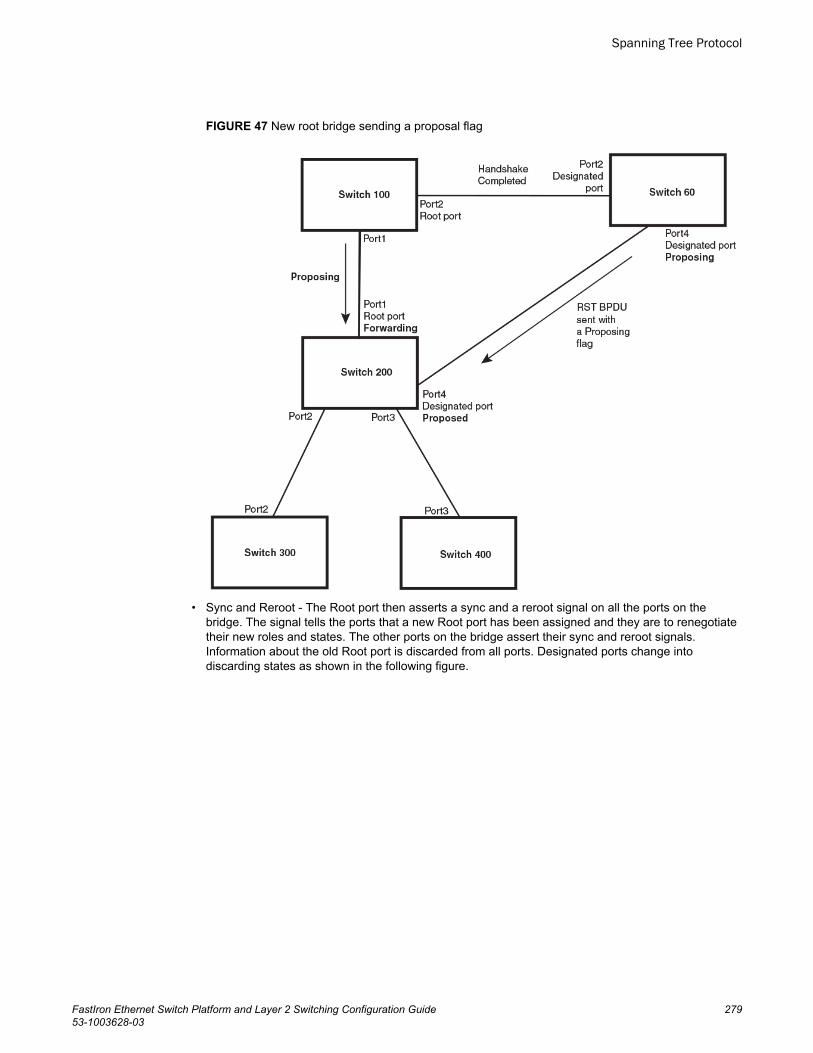
FIGURE 47 New root bridge sending a proposal flag
• Sync and Reroot - The Root port then asserts a sync and a reroot signal on all the ports on thebridge. The signal tells the ports that a new Root port has been assigned and they are to renegotiatetheir new roles and states. The other ports on the bridge assert their sync and reroot signals.Information about the old Root port is discarded from all ports. Designated ports change intodiscarding states as shown in the following figure.
Spanning Tree Protocol
FastIron Ethernet Switch Platform and Layer 2 Switching Configuration Guide 27953-1003628-03
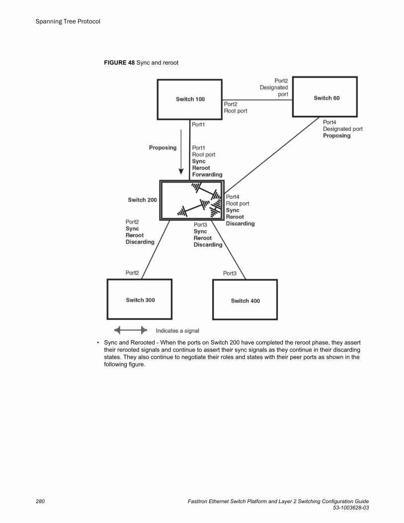
FIGURE 48 Sync and reroot
• Sync and Rerooted - When the ports on Switch 200 have completed the reroot phase, they asserttheir rerooted signals and continue to assert their sync signals as they continue in their discardingstates. They also continue to negotiate their roles and states with their peer ports as shown in thefollowing figure.
Spanning Tree Protocol
280 FastIron Ethernet Switch Platform and Layer 2 Switching Configuration Guide53-1003628-03
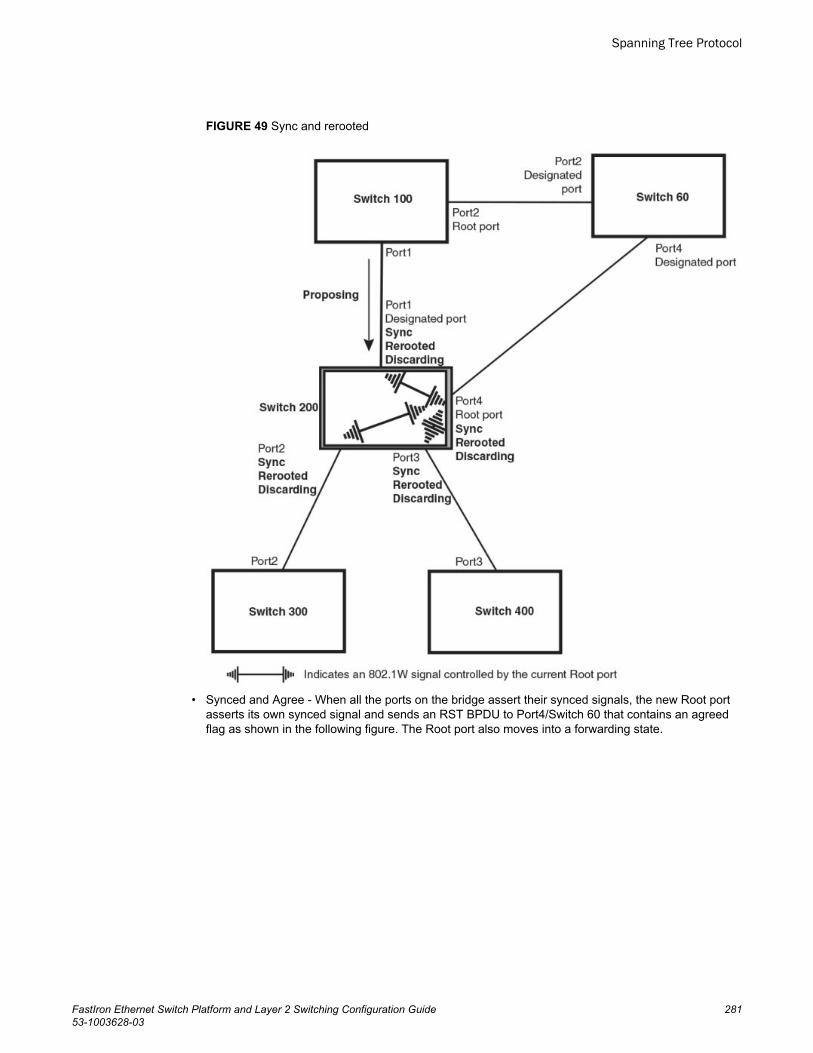
FIGURE 49 Sync and rerooted
• Synced and Agree - When all the ports on the bridge assert their synced signals, the new Root portasserts its own synced signal and sends an RST BPDU to Port4/Switch 60 that contains an agreedflag as shown in the following figure. The Root port also moves into a forwarding state.
Spanning Tree Protocol
FastIron Ethernet Switch Platform and Layer 2 Switching Configuration Guide 28153-1003628-03
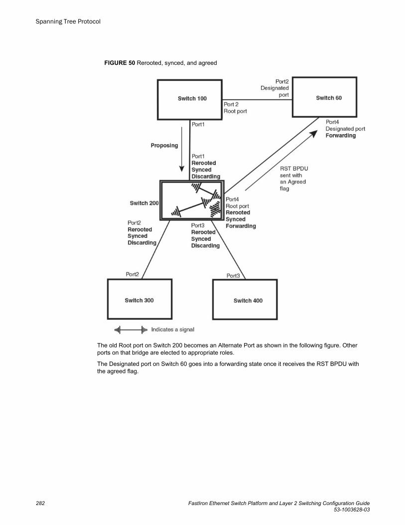
FIGURE 50 Rerooted, synced, and agreed
The old Root port on Switch 200 becomes an Alternate Port as shown in the following figure. Otherports on that bridge are elected to appropriate roles.
The Designated port on Switch 60 goes into a forwarding state once it receives the RST BPDU withthe agreed flag.
Spanning Tree Protocol
282 FastIron Ethernet Switch Platform and Layer 2 Switching Configuration Guide53-1003628-03
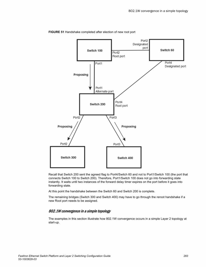
FIGURE 51 Handshake completed after election of new root port
Recall that Switch 200 sent the agreed flag to Port4/Switch 60 and not to Port1/Switch 100 (the port thatconnects Switch 100 to Switch 200). Therefore, Port1/Switch 100 does not go into forwarding stateinstantly. It waits until two instances of the forward delay timer expires on the port before it goes intoforwarding state.
At this point the handshake between the Switch 60 and Switch 200 is complete.
The remaining bridges (Switch 300 and Switch 400) may have to go through the reroot handshake if anew Root port needs to be assigned.
802.1W convergence in a simple topology
The examples in this section illustrate how 802.1W convergence occurs in a simple Layer 2 topology atstart-up.
802.1W convergence in a simple topology
FastIron Ethernet Switch Platform and Layer 2 Switching Configuration Guide 28353-1003628-03
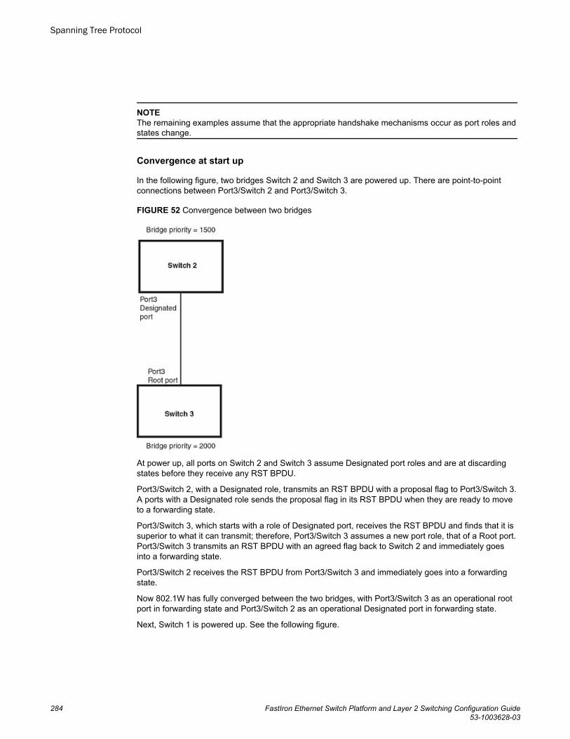
NOTEThe remaining examples assume that the appropriate handshake mechanisms occur as port roles andstates change.
Convergence at start up
In the following figure, two bridges Switch 2 and Switch 3 are powered up. There are point-to-pointconnections between Port3/Switch 2 and Port3/Switch 3.
FIGURE 52 Convergence between two bridges
At power up, all ports on Switch 2 and Switch 3 assume Designated port roles and are at discardingstates before they receive any RST BPDU.
Port3/Switch 2, with a Designated role, transmits an RST BPDU with a proposal flag to Port3/Switch 3.A ports with a Designated role sends the proposal flag in its RST BPDU when they are ready to moveto a forwarding state.
Port3/Switch 3, which starts with a role of Designated port, receives the RST BPDU and finds that it issuperior to what it can transmit; therefore, Port3/Switch 3 assumes a new port role, that of a Root port.Port3/Switch 3 transmits an RST BPDU with an agreed flag back to Switch 2 and immediately goesinto a forwarding state.
Port3/Switch 2 receives the RST BPDU from Port3/Switch 3 and immediately goes into a forwardingstate.
Now 802.1W has fully converged between the two bridges, with Port3/Switch 3 as an operational rootport in forwarding state and Port3/Switch 2 as an operational Designated port in forwarding state.
Next, Switch 1 is powered up. See the following figure.
Spanning Tree Protocol
284 FastIron Ethernet Switch Platform and Layer 2 Switching Configuration Guide53-1003628-03
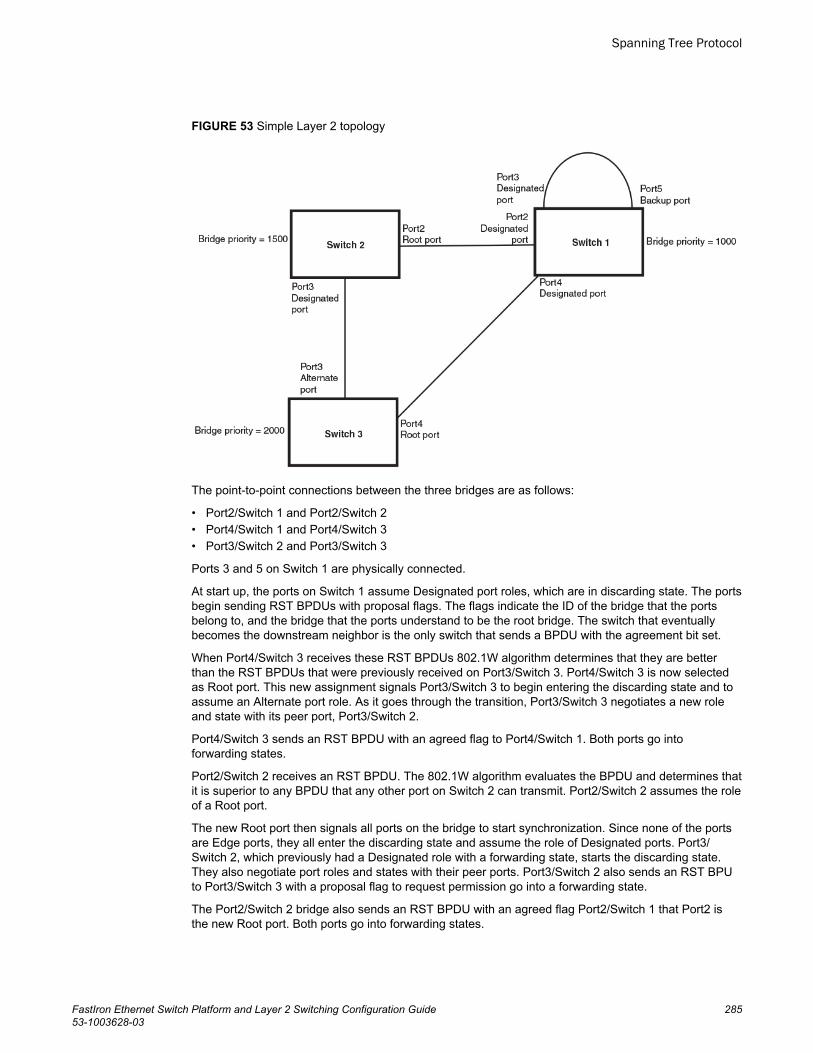
FIGURE 53 Simple Layer 2 topology
The point-to-point connections between the three bridges are as follows:
• Port2/Switch 1 and Port2/Switch 2• Port4/Switch 1 and Port4/Switch 3• Port3/Switch 2 and Port3/Switch 3
Ports 3 and 5 on Switch 1 are physically connected.
At start up, the ports on Switch 1 assume Designated port roles, which are in discarding state. The portsbegin sending RST BPDUs with proposal flags. The flags indicate the ID of the bridge that the portsbelong to, and the bridge that the ports understand to be the root bridge. The switch that eventuallybecomes the downstream neighbor is the only switch that sends a BPDU with the agreement bit set.
When Port4/Switch 3 receives these RST BPDUs 802.1W algorithm determines that they are betterthan the RST BPDUs that were previously received on Port3/Switch 3. Port4/Switch 3 is now selectedas Root port. This new assignment signals Port3/Switch 3 to begin entering the discarding state and toassume an Alternate port role. As it goes through the transition, Port3/Switch 3 negotiates a new roleand state with its peer port, Port3/Switch 2.
Port4/Switch 3 sends an RST BPDU with an agreed flag to Port4/Switch 1. Both ports go intoforwarding states.
Port2/Switch 2 receives an RST BPDU. The 802.1W algorithm evaluates the BPDU and determines thatit is superior to any BPDU that any other port on Switch 2 can transmit. Port2/Switch 2 assumes the roleof a Root port.
The new Root port then signals all ports on the bridge to start synchronization. Since none of the portsare Edge ports, they all enter the discarding state and assume the role of Designated ports. Port3/Switch 2, which previously had a Designated role with a forwarding state, starts the discarding state.They also negotiate port roles and states with their peer ports. Port3/Switch 2 also sends an RST BPUto Port3/Switch 3 with a proposal flag to request permission go into a forwarding state.
The Port2/Switch 2 bridge also sends an RST BPDU with an agreed flag Port2/Switch 1 that Port2 isthe new Root port. Both ports go into forwarding states.
Spanning Tree Protocol
FastIron Ethernet Switch Platform and Layer 2 Switching Configuration Guide 28553-1003628-03
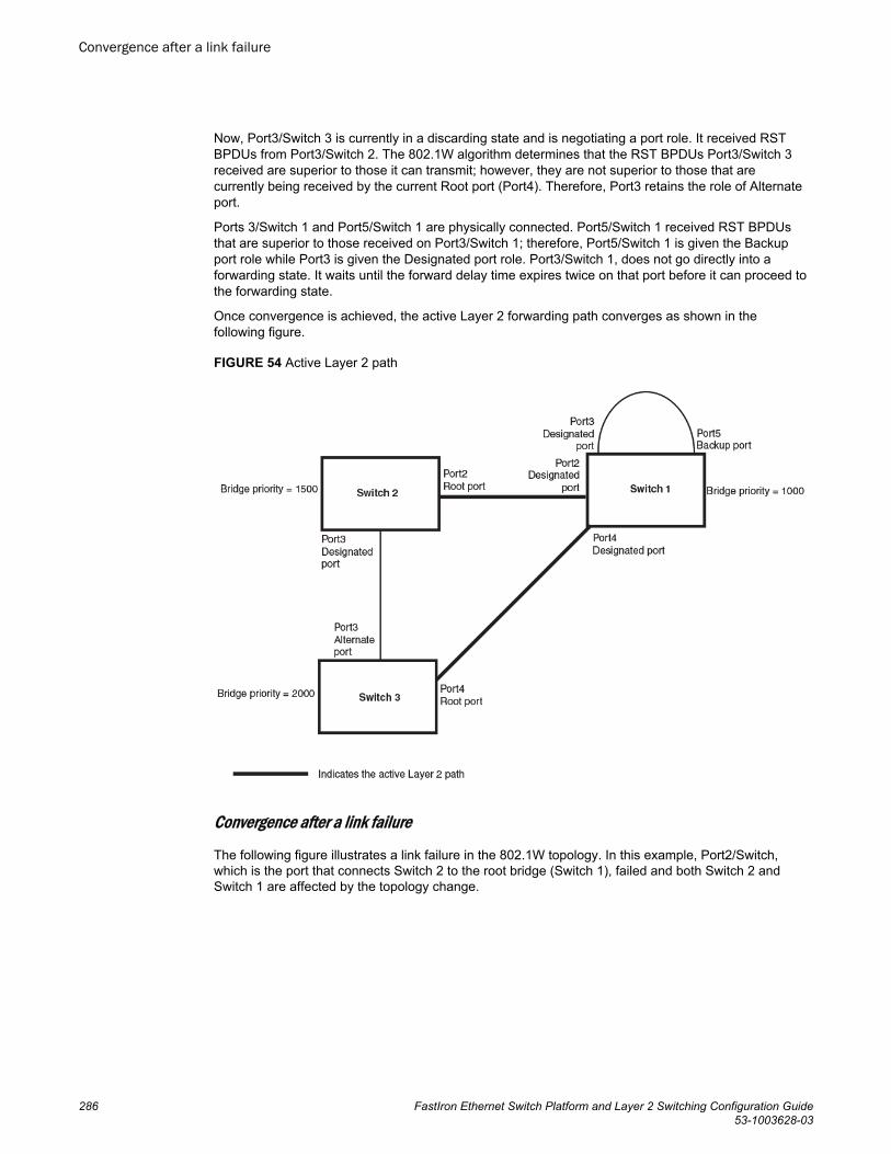
Now, Port3/Switch 3 is currently in a discarding state and is negotiating a port role. It received RSTBPDUs from Port3/Switch 2. The 802.1W algorithm determines that the RST BPDUs Port3/Switch 3received are superior to those it can transmit; however, they are not superior to those that arecurrently being received by the current Root port (Port4). Therefore, Port3 retains the role of Alternateport.
Ports 3/Switch 1 and Port5/Switch 1 are physically connected. Port5/Switch 1 received RST BPDUsthat are superior to those received on Port3/Switch 1; therefore, Port5/Switch 1 is given the Backupport role while Port3 is given the Designated port role. Port3/Switch 1, does not go directly into aforwarding state. It waits until the forward delay time expires twice on that port before it can proceed tothe forwarding state.
Once convergence is achieved, the active Layer 2 forwarding path converges as shown in thefollowing figure.
FIGURE 54 Active Layer 2 path
Convergence after a link failure
The following figure illustrates a link failure in the 802.1W topology. In this example, Port2/Switch,which is the port that connects Switch 2 to the root bridge (Switch 1), failed and both Switch 2 andSwitch 1 are affected by the topology change.
Convergence after a link failure
286 FastIron Ethernet Switch Platform and Layer 2 Switching Configuration Guide53-1003628-03
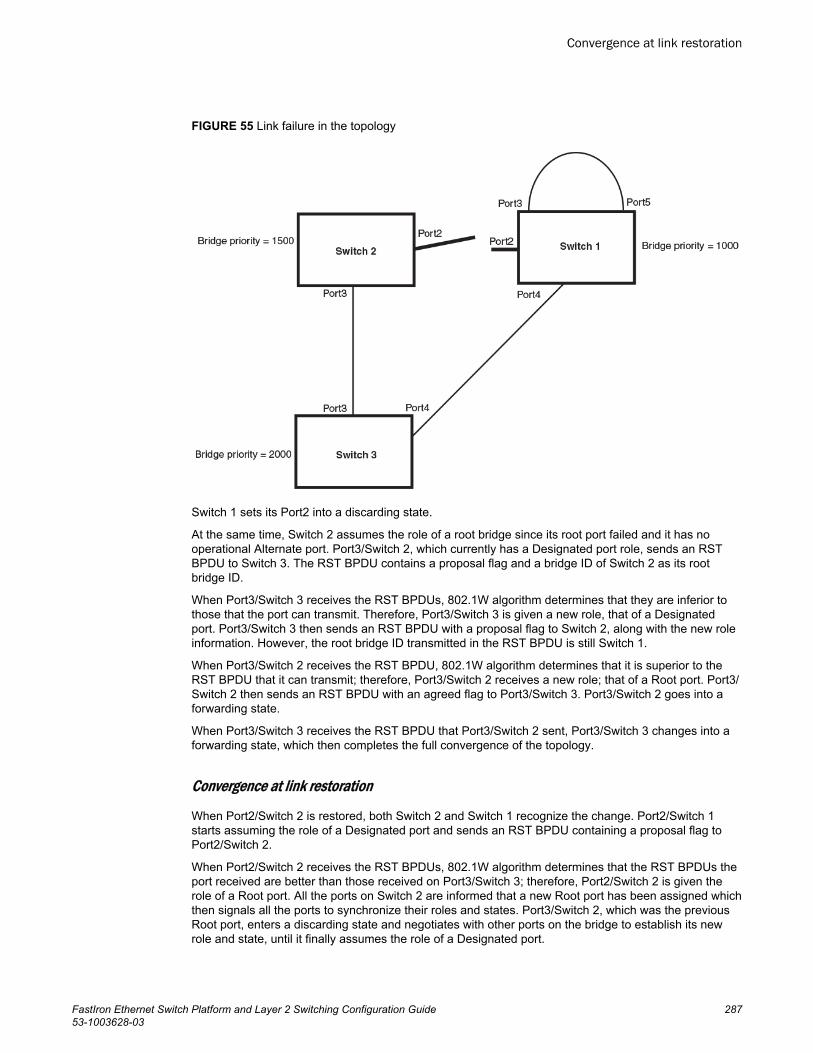
FIGURE 55 Link failure in the topology
Switch 1 sets its Port2 into a discarding state.
At the same time, Switch 2 assumes the role of a root bridge since its root port failed and it has nooperational Alternate port. Port3/Switch 2, which currently has a Designated port role, sends an RSTBPDU to Switch 3. The RST BPDU contains a proposal flag and a bridge ID of Switch 2 as its rootbridge ID.
When Port3/Switch 3 receives the RST BPDUs, 802.1W algorithm determines that they are inferior tothose that the port can transmit. Therefore, Port3/Switch 3 is given a new role, that of a Designatedport. Port3/Switch 3 then sends an RST BPDU with a proposal flag to Switch 2, along with the new roleinformation. However, the root bridge ID transmitted in the RST BPDU is still Switch 1.
When Port3/Switch 2 receives the RST BPDU, 802.1W algorithm determines that it is superior to theRST BPDU that it can transmit; therefore, Port3/Switch 2 receives a new role; that of a Root port. Port3/Switch 2 then sends an RST BPDU with an agreed flag to Port3/Switch 3. Port3/Switch 2 goes into aforwarding state.
When Port3/Switch 3 receives the RST BPDU that Port3/Switch 2 sent, Port3/Switch 3 changes into aforwarding state, which then completes the full convergence of the topology.
Convergence at link restoration
When Port2/Switch 2 is restored, both Switch 2 and Switch 1 recognize the change. Port2/Switch 1starts assuming the role of a Designated port and sends an RST BPDU containing a proposal flag toPort2/Switch 2.
When Port2/Switch 2 receives the RST BPDUs, 802.1W algorithm determines that the RST BPDUs theport received are better than those received on Port3/Switch 3; therefore, Port2/Switch 2 is given therole of a Root port. All the ports on Switch 2 are informed that a new Root port has been assigned whichthen signals all the ports to synchronize their roles and states. Port3/Switch 2, which was the previousRoot port, enters a discarding state and negotiates with other ports on the bridge to establish its newrole and state, until it finally assumes the role of a Designated port.
Convergence at link restoration
FastIron Ethernet Switch Platform and Layer 2 Switching Configuration Guide 28753-1003628-03
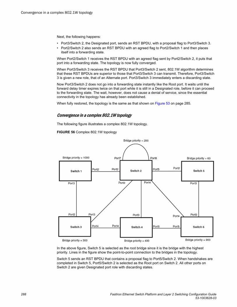
Next, the following happens:
• Port3/Switch 2, the Designated port, sends an RST BPDU, with a proposal flag to Port3/Switch 3.• Port2/Switch 2 also sends an RST BPDU with an agreed flag to Port2/Switch 1 and then places
itself into a forwarding state.
When Port2/Switch 1 receives the RST BPDU with an agreed flag sent by Port2/Switch 2, it puts thatport into a forwarding state. The topology is now fully converged.
When Port3/Switch 3 receives the RST BPDU that Port3/Switch 2 sent, 802.1W algorithm determinesthat these RST BPDUs are superior to those that Port3/Switch 3 can transmit. Therefore, Port3/Switch3 is given a new role, that of an Alternate port. Port3/Switch 3 immediately enters a discarding state.
Now Port3/Switch 2 does not go into a forwarding state instantly like the Root port. It waits until theforward delay timer expires twice on that port while it is still in a Designated role, before it can proceedto the forwarding state. The wait, however, does not cause a denial of service, since the essentialconnectivity in the topology has already been established.
When fully restored, the topology is the same as that shown on Figure 53 on page 285.
Convergence in a complex 802.1W topology
The following figure illustrates a complex 802.1W topology.
FIGURE 56 Complex 802.1W topology
In the above figure, Switch 5 is selected as the root bridge since it is the bridge with the highestpriority. Lines in the figure show the point-to-point connection to the bridges in the topology.
Switch 5 sends an RST BPDU that contains a proposal flag to Port5/Switch 2. When handshakes arecompleted in Switch 5, Port5/Switch 2 is selected as the Root port on Switch 2. All other ports onSwitch 2 are given Designated port role with discarding states.
Convergence in a complex 802.1W topology
288 FastIron Ethernet Switch Platform and Layer 2 Switching Configuration Guide53-1003628-03
Port5/Switch 2 then sends an RST BPDU with an agreed flag to Switch 5 to confirm that it is the newRoot port and the port enters a forwarding state. Port7 and Port8 are informed of the identity of the newRoot port. 802.1W algorithm selects Port7 as the Designated port while Port8 becomes the Backupport.
Port3/Switch 5 sends an RST BPDU to Port3/Switch 6 with a proposal flag. When Port3/Switch 5receives the RST BPDU, handshake mechanisms select Port3 as the Root port of Switch 6. All otherports are given a Designated port role with discarding states. Port3/Switch 6 then sends an RST BPDUwith an agreed flag to Port3/Switch 5 to confirm that it is the Root port. The Root port then goes into aforwarding state.
Now, Port4/Switch 6 receives RST BPDUs that are superior to what it can transmit; therefore, it is giventhe Alternate port role. The port remains in discarding state.
Port5/Switch 6 receives RST BPDUs that are inferior to what it can transmit. The port is then given aDesignated port role.
Next Switch 2 sends RST BPDUs with a proposal flag to Port3/Switch 4. Port3 becomes the Root portfor the bridge; all other ports are given a Designated port role with discarding states. Port3/Switch 4sends an RST BPDU with an agreed flag to Switch 2 to confirm that it is the new Root port. The portthen goes into a forwarding state.
Now Port4/Switch 4 receives an RST BPDU that is superior to what it can transmit. The port is thengiven an Alternate port role, and remains in discarding state.
Likewise, Port5/Switch 4 receives an RST BPDU that is superior to what it can transmit. The port is alsogiven an Alternate port role, and remains in discarding state.
Port2/Switch 2 transmits an RST BPDU with a proposal flag to Port2/Switch 1. Port2/Switch 1 becomesthe Root port. All other ports on Switch 1 are given Designated port roles with discarding states.
Port2/Switch 1 sends an RST BPDU with an agreed flag to Port2/Switch 2 and Port2/Switch 1 goes intoa forwarding state.
Port3/Switch 1 receives an RST BPDUs that is inferior to what it can transmit; therefore, the port retainsits Designated port role and goes into forwarding state only after the forward delay timer expires twiceon that port while it is still in a Designated role.
Port3/Switch 2 sends an RST BPDU to Port3/Switch 3 that contains a proposal flag. Port3/Switch 3becomes the Root port, while all other ports on Switch 3 are given Designated port roles and go intodiscarding states. Port3/Switch 3 sends an RST BPDU with an agreed flag to Port3/Switch 2 and Port3/Switch 3 goes into a forwarding state.
Now, Port2/Switch 3 receives an RST BPDUs that is superior to what it can transmit so that port isgiven an Alternate port state.
Port4/Switch 3 receives an RST BPDU that is inferior to what it can transmit; therefore, the port retainsits Designated port role.
Ports on all the bridges in the topology with Designated port roles that received RST BPDUs withagreed flags go into forwarding states instantly. However, Designated ports that did not receive RSTBPDUs with agreed flags must wait until the forward delay timer expires twice on those port. Only thenwill these port move into forwarding states.
The entire 802.1W topology converges in less than 300 msec and the essential connectivity isestablished between the designated ports and their connected root ports.
After convergence is complete, the following figure shows the active Layer 2 path of the topology in Figure 56 .
Spanning Tree Protocol
FastIron Ethernet Switch Platform and Layer 2 Switching Configuration Guide 28953-1003628-03
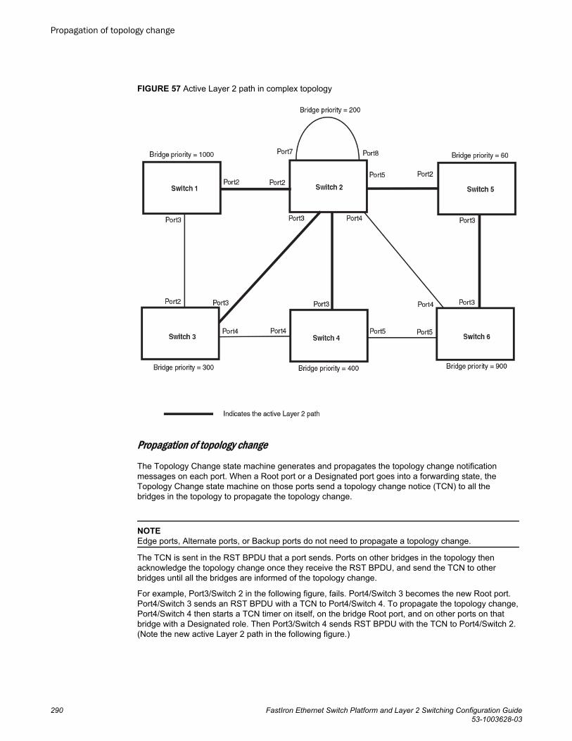
FIGURE 57 Active Layer 2 path in complex topology
Propagation of topology change
The Topology Change state machine generates and propagates the topology change notificationmessages on each port. When a Root port or a Designated port goes into a forwarding state, theTopology Change state machine on those ports send a topology change notice (TCN) to all thebridges in the topology to propagate the topology change.
NOTEEdge ports, Alternate ports, or Backup ports do not need to propagate a topology change.
The TCN is sent in the RST BPDU that a port sends. Ports on other bridges in the topology thenacknowledge the topology change once they receive the RST BPDU, and send the TCN to otherbridges until all the bridges are informed of the topology change.
For example, Port3/Switch 2 in the following figure, fails. Port4/Switch 3 becomes the new Root port.Port4/Switch 3 sends an RST BPDU with a TCN to Port4/Switch 4. To propagate the topology change,Port4/Switch 4 then starts a TCN timer on itself, on the bridge Root port, and on other ports on thatbridge with a Designated role. Then Port3/Switch 4 sends RST BPDU with the TCN to Port4/Switch 2.(Note the new active Layer 2 path in the following figure.)
Propagation of topology change
290 FastIron Ethernet Switch Platform and Layer 2 Switching Configuration Guide53-1003628-03
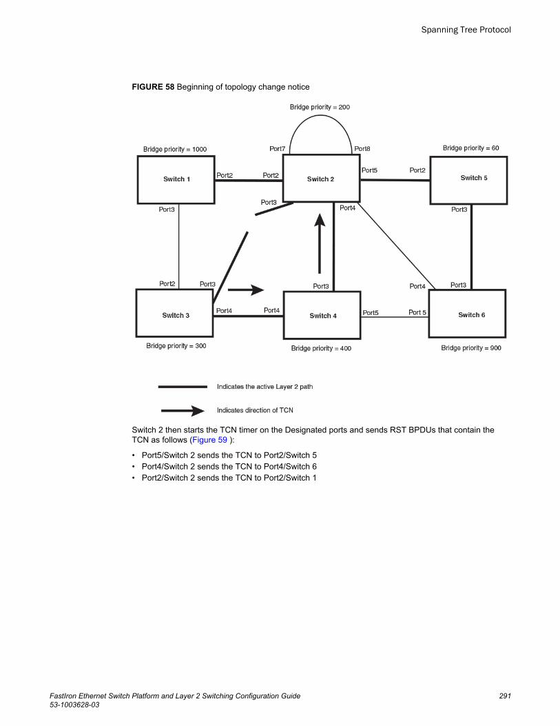
FIGURE 58 Beginning of topology change notice
Switch 2 then starts the TCN timer on the Designated ports and sends RST BPDUs that contain theTCN as follows (Figure 59 ):
• Port5/Switch 2 sends the TCN to Port2/Switch 5• Port4/Switch 2 sends the TCN to Port4/Switch 6• Port2/Switch 2 sends the TCN to Port2/Switch 1
Spanning Tree Protocol
FastIron Ethernet Switch Platform and Layer 2 Switching Configuration Guide 29153-1003628-03
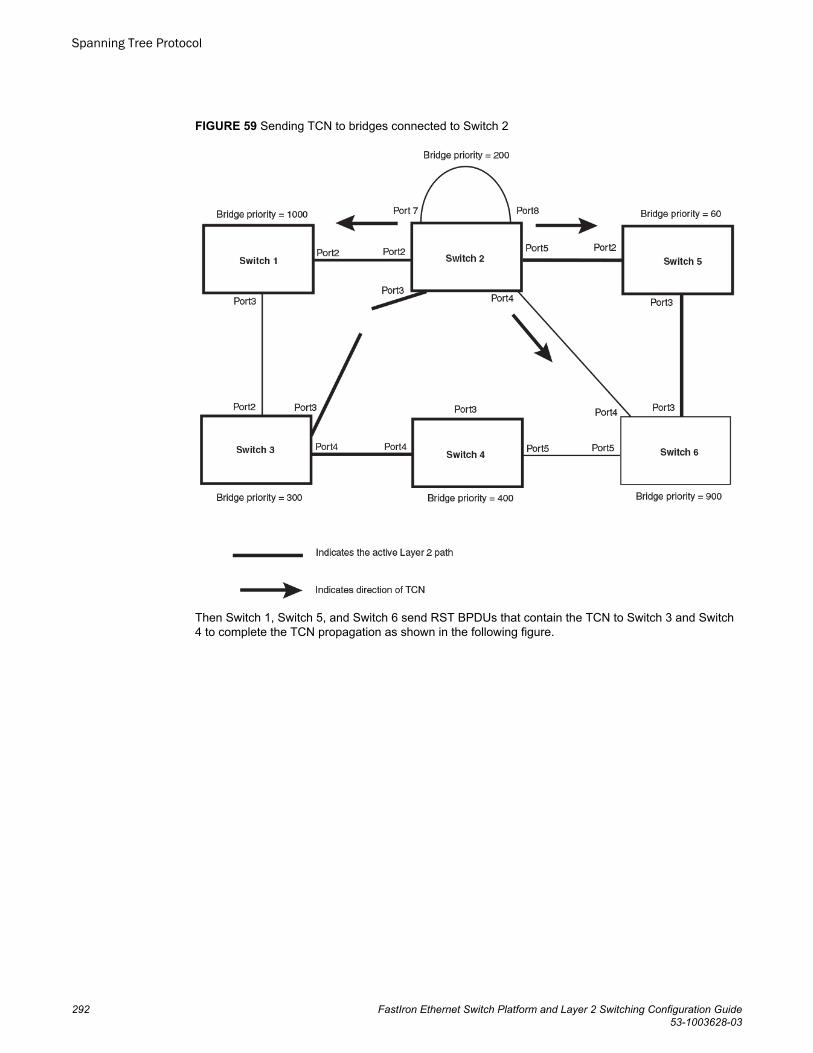
FIGURE 59 Sending TCN to bridges connected to Switch 2
Then Switch 1, Switch 5, and Switch 6 send RST BPDUs that contain the TCN to Switch 3 and Switch4 to complete the TCN propagation as shown in the following figure.
Spanning Tree Protocol
292 FastIron Ethernet Switch Platform and Layer 2 Switching Configuration Guide53-1003628-03
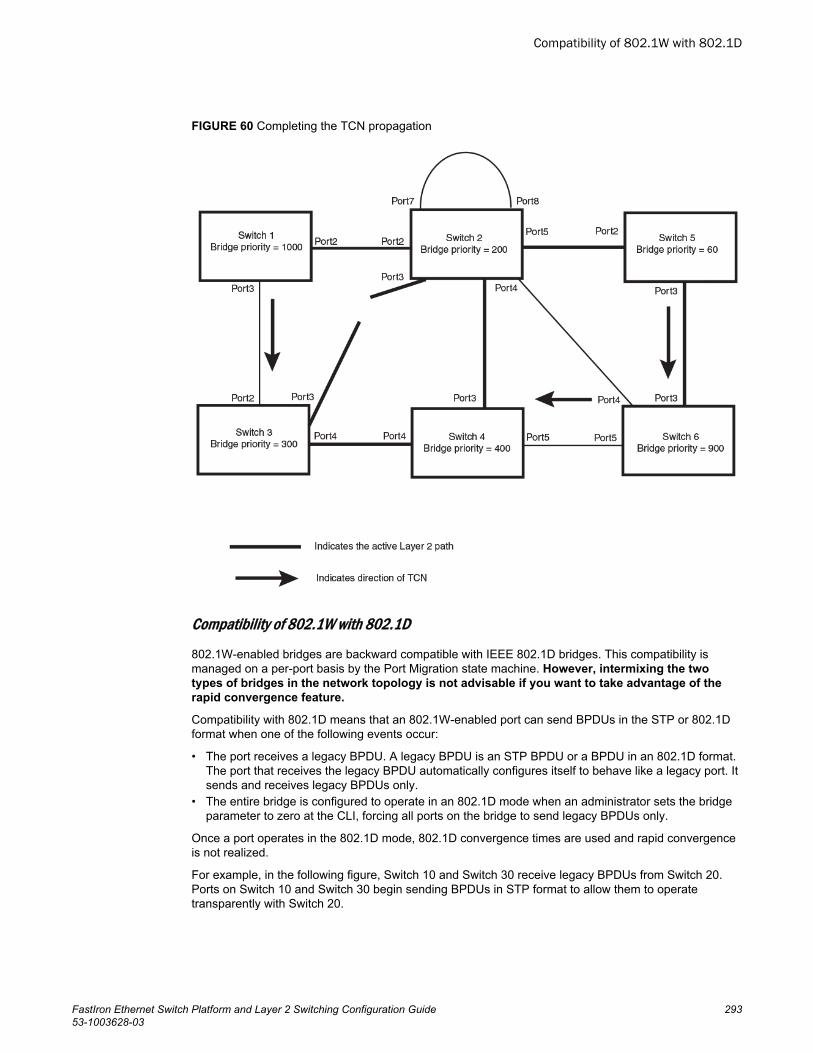
FIGURE 60 Completing the TCN propagation
Compatibility of 802.1W with 802.1D
802.1W-enabled bridges are backward compatible with IEEE 802.1D bridges. This compatibility ismanaged on a per-port basis by the Port Migration state machine. However, intermixing the twotypes of bridges in the network topology is not advisable if you want to take advantage of therapid convergence feature.
Compatibility with 802.1D means that an 802.1W-enabled port can send BPDUs in the STP or 802.1Dformat when one of the following events occur:
• The port receives a legacy BPDU. A legacy BPDU is an STP BPDU or a BPDU in an 802.1D format.The port that receives the legacy BPDU automatically configures itself to behave like a legacy port. Itsends and receives legacy BPDUs only.
• The entire bridge is configured to operate in an 802.1D mode when an administrator sets the bridgeparameter to zero at the CLI, forcing all ports on the bridge to send legacy BPDUs only.
Once a port operates in the 802.1D mode, 802.1D convergence times are used and rapid convergenceis not realized.
For example, in the following figure, Switch 10 and Switch 30 receive legacy BPDUs from Switch 20.Ports on Switch 10 and Switch 30 begin sending BPDUs in STP format to allow them to operatetransparently with Switch 20.
Compatibility of 802.1W with 802.1D
FastIron Ethernet Switch Platform and Layer 2 Switching Configuration Guide 29353-1003628-03
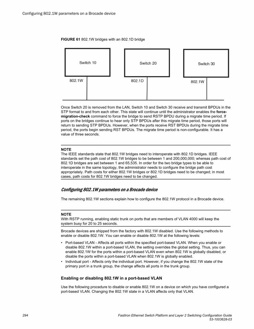
FIGURE 61 802.1W bridges with an 802.1D bridge
Once Switch 20 is removed from the LAN, Switch 10 and Switch 30 receive and transmit BPDUs in theSTP format to and from each other. This state will continue until the administrator enables the force-migration-check command to force the bridge to send RSTP BPDU during a migrate time period. Ifports on the bridges continue to hear only STP BPDUs after this migrate time period, those ports willreturn to sending STP BPDUs. However, when the ports receive RST BPDUs during the migrate timeperiod, the ports begin sending RST BPDUs. The migrate time period is non-configurable. It has avalue of three seconds.
NOTEThe IEEE standards state that 802.1W bridges need to interoperate with 802.1D bridges. IEEEstandards set the path cost of 802.1W bridges to be between 1 and 200,000,000; whereas path cost of802.1D bridges are set between 1 and 65,535. In order for the two bridge types to be able tointeroperate in the same topology, the administrator needs to configure the bridge path costappropriately. Path costs for either 802.1W bridges or 802.1D bridges need to be changed; in mostcases, path costs for 802.1W bridges need to be changed.
Configuring 802.1W parameters on a Brocade device
The remaining 802.1W sections explain how to configure the 802.1W protocol in a Brocade device.
NOTEWith RSTP running, enabling static trunk on ports that are members of VLAN 4000 will keep thesystem busy for 20 to 25 seconds.
Brocade devices are shipped from the factory with 802.1W disabled. Use the following methods toenable or disable 802.1W. You can enable or disable 802.1W at the following levels:
• Port-based VLAN - Affects all ports within the specified port-based VLAN. When you enable ordisable 802.1W within a port-based VLAN, the setting overrides the global setting. Thus, you canenable 802.1W for the ports within a port-based VLAN even when 802.1W is globally disabled, ordisable the ports within a port-based VLAN when 802.1W is globally enabled.
• Individual port - Affects only the individual port. However, if you change the 802.1W state of theprimary port in a trunk group, the change affects all ports in the trunk group.
Enabling or disabling 802.1W in a port-based VLAN
Use the following procedure to disable or enable 802.1W on a device on which you have configured aport-based VLAN. Changing the 802.1W state in a VLAN affects only that VLAN.
Configuring 802.1W parameters on a Brocade device
294 FastIron Ethernet Switch Platform and Layer 2 Switching Configuration Guide53-1003628-03
To enable 802.1W for all ports in a port-based VLAN, enter commands such as the following.
device(config)#vlan 10device(config-vlan-10)#spanning-tree 802-1wSyntax: [no] spanning-tree 802-1w
Note regarding pasting 802.1W settings into the running configuration
If you paste 802.1W settings into the running configuration, and the pasted configuration includes portsthat are already up, the ports will initially operate in STP legacy mode before operating in 802.1W RSTPmode. For example, the following pasted configuration will cause ports e 1 and e 2 to temporarilyoperate in STP legacy mode, because these ports are already up and running.
conf tvlan 120tag e 1 to e 2spanning-tree 802-1wspanning-tree 802-1w priority 1001endTo avoid this issue, 802.1W commands/settings that are pasted into the configuration should be in thefollowing order.
1. Ports that are not yet connected
2. 802.1W RSTP settings
3. Ports that are already up
Example
conf tvlan 120untag e 3spanning-tree 802-1wspanning-tree 802-1w priority 1001tag e 1 to 2endIn the above configuration, untagged port e3 is added to VLAN 120 before the 802.1W RSTP settings,and ports e1 and e2 are added after the 802.1W RSTP settings. When these commands are pasted intothe running configuration, the ports will properly operate in 802.1W RSTP mode.
Enabling or disabling 802.1W on a single spanning tree
To enable 802.1W for all ports of a single spanning tree, enter a command such as the following.
device(config-vlan-10)#spanning-tree single 802-1wSyntax: [no] spanning-tree single 802-1w
Disabling or enabling 802.1W on an individual port
The spanning-tree 802-1w or spanning-tree single 802-1w command must be used to initially enable802.1W on ports. Both commands enable 802.1W on all ports that belong to the VLAN or to the singlespanning tree.
Once 802.1W is enabled on a port, it can be disabled on individual ports. 802.1W that have beendisabled on individual ports can then be enabled as required.
Spanning Tree Protocol
FastIron Ethernet Switch Platform and Layer 2 Switching Configuration Guide 29553-1003628-03
NOTEIf you change the 802.1W state of the primary port in a trunk group, the change affects all ports in thattrunk group.
To disable or enable 802.1W on an individual port, enter commands such as the following.
device(config)#interface e 1device(config-if-e1000-1)#no spanning-treeSyntax: [no] spanning-tree
Changing 802.1W bridge parameters
When you make changes to 802.1W bridge parameters, the changes are applied to individual ports onthe bridge. To change 802.1W bridge parameters, use the following methods.
To designate a priority for a bridge, enter a command such as the following.
device(config)#spanning-tree 802-1w priority 10The command in this example changes the priority on a device on which you have not configured port-based VLANs. The change applies to the default VLAN. If you have configured a port-based VLAN onthe device, you can configure the parameters only at the configuration level for individual VLANs.Enter commands such as the following.
device(config)#vlan 20device(config-vlan-20)#spanning-tree 802-1w priority 0To make this change in the default VLAN, enter the following commands.
device(config)#vlan 1device(config-vlan-1)#spanning-tree 802-1w priority 0Syntax: spanning-tree 802-1w [ forward-delay value] | [hello-time value] | [max-age time] | [force-version value] | [priority value]
The forward-delay value parameter specifies how long a port waits before it forwards an RST BPDUafter a topology change. This can be a value from 4 - 30 seconds. The default is 15 seconds.
The hello-time value parameter specifies the interval between two hello packets. This parameter canhave a value from 1 - 10 seconds. The default is 2 seconds.
The max-age value parameter specifies the amount of time the device waits to receive a hello packetbefore it initiates a topology change. You can specify a value from 6 - 40 seconds. The default is 20seconds.
The value of max-age must be greater than the value of forward-delay to ensure that thedownstream bridges do not age out faster than the upstream bridges (those bridges that are closer tothe root bridge).
The force-version value parameter forces the bridge to send BPDUs in a specific format. You canspecify one of the following values:
• 0 - The STP compatibility mode. Only STP (or legacy) BPDUs will be sent.• 2 - The default. RST BPDUs will be sent unless a legacy bridge is detected. If a legacy bridge is
detected, STP BPDUs will be sent instead.
The default is 2.
Spanning Tree Protocol
296 FastIron Ethernet Switch Platform and Layer 2 Switching Configuration Guide53-1003628-03
The priority value parameter specifies the priority of the bridge. You can enter a value from 0 - 65535.A lower numerical value means the bridge has a higher priority. Thus, the highest priority is 0. Thedefault is 32768.
You can specify some or all of these parameters on the same command line. If you specify more thanone parameter, you must specify them in the order shown above, from left to right.
Changing port parameters
The 802.1W port commands can be enabled on individual ports or on multiple ports, such as all portsthat belong to a VLAN.
The 802.1W port parameters are preconfigured with default values. If the default parameters meet yournetwork requirements, no other action is required.
You can change the following 802.1W port parameters using the following method.
device(config)#vlan 10device(config-vlan-10)#spanning-tree 802-1w ethernet 5 path-cost 15 priority 64Syntax: spanning-tree 802-1w ethernet port path-cost value | priority value | [admin-edge-port] |[admin-pt2pt-mac] | [force-migration-check]
The path-cost value parameter specifies the cost of the port path to the root bridge. 802.1W prefers thepath with the lowest cost. You can specify a value from 1 - 20,000,000. The following table shows therecommended path cost values from the IEEE standards.
Recommended path cost values of 802.1WTABLE 50
Link speed Recommended (Default) 802.1Wpath cost values
Recommended 802.1W patch costrange
Less than 100 kilobits per second 200,000,000 20,000,000 – 200,000,000
1 Megabit per second 20,000,000 2,000,000 – 200,000,000
10 Megabits per second 2,000,000 200,000 – 200,000,000
100 Megabits per second 200,000 20,000 – 200,000,000
1 Gbps per second 20,000 2,000 – 200,000,000
10 Gbps per second 2,000 200 – 20,000
100 Gbps per second 200 20 – 2,000
1 Terabits per second 20 2 – 200
10 Terabits per second 2 1 – 20
• You can specify a value from 0 – 240, in increments of 16. If you enter a value that is not divisible by16, the software returns an error message. The default value is 128. A higher numerical value meansa lower priority; thus, the highest priority is 0.
• Set the admin-edge-port to enabled or disabled. If set to enabled, then the port becomes an edgeport in the domain.
Set the admin-pt2pt-mac to enabled or disabled. If set to enabled, then a port is connected to anotherport through a point-to-point link. The point-to-point link increases the speed of convergence. Thisparameter, however, does not auto-detect whether or not the link is a physical point-to-point link.
The force-migration-check parameter forces the specified port to sent one RST BPDU. If only STPBPDUs are received in response to the sent RST BPDU, then the port will go return to sending STPBPDUs.
Spanning Tree Protocol
FastIron Ethernet Switch Platform and Layer 2 Switching Configuration Guide 29753-1003628-03
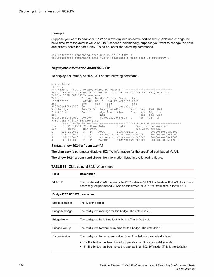
Example
Suppose you want to enable 802.1W on a system with no active port-based VLANs and change thehello-time from the default value of 2 to 8 seconds. Additionally, suppose you want to change the pathand priority costs for port 5 only. To do so, enter the following commands.
device(config)#spanning-tree 802-1w hello-time 8 device(config)#spanning-tree 802-1w ethernet 5 path-cost 15 priority 64
Displaying information about 802-1W
To display a summary of 802-1W, use the following command.
device#show 802-1w --- VLAN 1 [ STP Instance owned by VLAN 1 ] ----------------------------VLAN 1 BPDU cam_index is 2 and the IGC and DMA master Are(HEX) 0 1 2 3Bridge IEEE 802.1W Parameters:Bridge Bridge Bridge Bridge Force txIdentifier MaxAge Hello FwdDly Version Holdhex sec sec sec cnt800000e080541700 20 2 15 Default 3RootBridge RootPath DesignatedBri- Root Max Fwd HelIdentifier Cost dge Identifier Port Age Dly lohex hex sec sec sec800000e0804c9c00 200000 800000e0804c9c00 1 20 15 2Port IEEE 802.1W Parameters: <--- Config Params -->|<-------------- Current state ----------------->Port Pri PortPath P2P Edge Role State Designa- DesignatedNum Cost Mac Port ted cost bridge1 128 200000 F F ROOT FORWARDING 0 800000e0804c9c002 128 200000 F F DESIGNATED FORWARDING 200000 800000e0805417003 128 200000 F F DESIGNATED FORWARDING 200000 800000e0805417004 128 200000 F F BACKUP DISCARDING 200000 800000e080541700Syntax: show 802-1w [ vlan vlan-id]
The vlan vlan-id parameter displays 802.1W information for the specified port-based VLAN.
The show 802-1w command shows the information listed in the following figure.
CLI display of 802.1W summary TABLE 51
Field Description
VLAN ID The port-based VLAN that owns the STP instance. VLAN 1 is the default VLAN. If you havenot configured port-based VLANs on this device, all 802.1W information is for VLAN 1.
Bridge IEEE 802.1W parameters
Bridge Identifier The ID of the bridge.
Bridge Max Age The configured max age for this bridge. The default is 20.
Bridge Hello The configured hello time for this bridge.The default is 2.
Bridge FwdDly The configured forward delay time for this bridge. The default is 15.
Force-Version The configured force version value. One of the following value is displayed:
• 0 - The bridge has been forced to operate in an STP compatibility mode.• 2 - The bridge has been forced to operate in an 802.1W mode. (This is the default.)
Displaying information about 802-1W
298 FastIron Ethernet Switch Platform and Layer 2 Switching Configuration Guide53-1003628-03
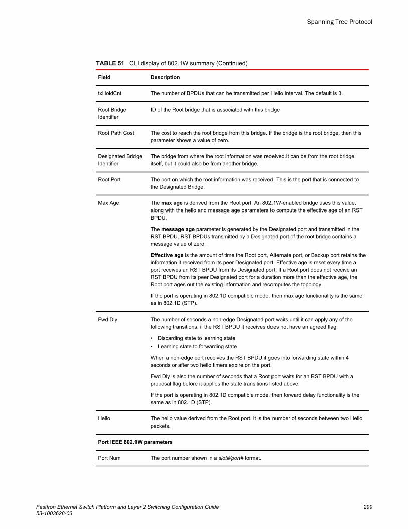
CLI display of 802.1W summary (Continued)TABLE 51
Field Description
txHoldCnt The number of BPDUs that can be transmitted per Hello Interval. The default is 3.
Root BridgeIdentifier
ID of the Root bridge that is associated with this bridge
Root Path Cost The cost to reach the root bridge from this bridge. If the bridge is the root bridge, then thisparameter shows a value of zero.
Designated BridgeIdentifier
The bridge from where the root information was received.It can be from the root bridgeitself, but it could also be from another bridge.
Root Port The port on which the root information was received. This is the port that is connected tothe Designated Bridge.
Max Age The max age is derived from the Root port. An 802.1W-enabled bridge uses this value,along with the hello and message age parameters to compute the effective age of an RSTBPDU.
The message age parameter is generated by the Designated port and transmitted in theRST BPDU. RST BPDUs transmitted by a Designated port of the root bridge contains amessage value of zero.
Effective age is the amount of time the Root port, Alternate port, or Backup port retains theinformation it received from its peer Designated port. Effective age is reset every time aport receives an RST BPDU from its Designated port. If a Root port does not receive anRST BPDU from its peer Designated port for a duration more than the effective age, theRoot port ages out the existing information and recomputes the topology.
If the port is operating in 802.1D compatible mode, then max age functionality is the sameas in 802.1D (STP).
Fwd Dly The number of seconds a non-edge Designated port waits until it can apply any of thefollowing transitions, if the RST BPDU it receives does not have an agreed flag:
• Discarding state to learning state• Learning state to forwarding state
When a non-edge port receives the RST BPDU it goes into forwarding state within 4seconds or after two hello timers expire on the port.
Fwd Dly is also the number of seconds that a Root port waits for an RST BPDU with aproposal flag before it applies the state transitions listed above.
If the port is operating in 802.1D compatible mode, then forward delay functionality is thesame as in 802.1D (STP).
Hello The hello value derived from the Root port. It is the number of seconds between two Hellopackets.
Port IEEE 802.1W parameters
Port Num The port number shown in a slot#/port# format.
Spanning Tree Protocol
FastIron Ethernet Switch Platform and Layer 2 Switching Configuration Guide 29953-1003628-03
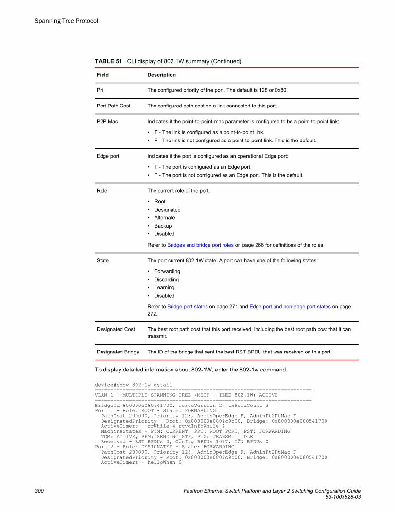
CLI display of 802.1W summary (Continued)TABLE 51
Field Description
Pri The configured priority of the port. The default is 128 or 0x80.
Port Path Cost The configured path cost on a link connected to this port.
P2P Mac Indicates if the point-to-point-mac parameter is configured to be a point-to-point link:
• T - The link is configured as a point-to-point link.• F - The link is not configured as a point-to-point link. This is the default.
Edge port Indicates if the port is configured as an operational Edge port:
• T - The port is configured as an Edge port.• F - The port is not configured as an Edge port. This is the default.
Role The current role of the port:
• Root• Designated• Alternate• Backup• Disabled
Refer to Bridges and bridge port roles on page 266 for definitions of the roles.
State The port current 802.1W state. A port can have one of the following states:
• Forwarding• Discarding• Learning• Disabled
Refer to Bridge port states on page 271 and Edge port and non-edge port states on page272.
Designated Cost The best root path cost that this port received, including the best root path cost that it cantransmit.
Designated Bridge The ID of the bridge that sent the best RST BPDU that was received on this port.
To display detailed information about 802-1W, enter the 802-1w command.
device#show 802-1w detail ======================================================================VLAN 1 - MULTIPLE SPANNING TREE (MSTP - IEEE 802.1W) ACTIVE======================================================================BridgeId 800000e080541700, forceVersion 2, txHoldCount 3Port 1 - Role: ROOT - State: FORWARDING PathCost 200000, Priority 128, AdminOperEdge F, AdminPt2PtMac F DesignatedPriority - Root: 0x800000e0804c9c00, Bridge: 0x800000e080541700 ActiveTimers - rrWhile 4 rcvdInfoWhile 4 MachineStates - PIM: CURRENT, PRT: ROOT_PORT, PST: FORWARDING TCM: ACTIVE, PPM: SENDING_STP, PTX: TRANSMIT_IDLE Received - RST BPDUs 0, Config BPDUs 1017, TCN BPDUs 0Port 2 - Role: DESIGNATED - State: FORWARDING PathCost 200000, Priority 128, AdminOperEdge F, AdminPt2PtMac F DesignatedPriority - Root: 0x800000e0804c9c00, Bridge: 0x800000e080541700 ActiveTimers - helloWhen 0
Spanning Tree Protocol
300 FastIron Ethernet Switch Platform and Layer 2 Switching Configuration Guide53-1003628-03
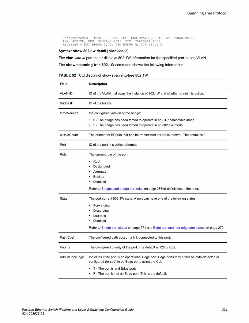
MachineStates - PIM: CURRENT, PRT: DESIGNATED_PORT, PST: FORWARDING TCM: ACTIVE, PPM: SENDING_RSTP, PTX: TRANSMIT_IDLE Received - RST BPDUs 0, Config BPDUs 0, TCN BPDUs 0Syntax: show 802-1w detail [ vlanvlan-id]
The vlan vlan-id parameter displays 802.1W information for the specified port-based VLAN.
The show spanning-tree 802.1W command shows the following information.
CLI display of show spanning-tree 802.1W TABLE 52
Field Description
VLAN ID ID of the VLAN that owns the instance of 802.1W and whether or not it is active.
Bridge ID ID of the bridge.
forceVersion the configured version of the bridge:
• 0 - The bridge has been forced to operate in an STP compatible mode.• 2 - The bridge has been forced to operate in an 802.1W mode.
txHoldCount The number of BPDUs that can be transmitted per Hello Interval. The default is 3.
Port ID of the port in slot#/port#format.
Role The current role of the port:
• Root• Designated• Alternate• Backup• Disabled
Refer to Bridges and bridge port roles on page 266for definitions of the roles.
State The port current 802.1W state. A port can have one of the following states:
• Forwarding• Discarding• Learning• Disabled
Refer to Bridge port states on page 271 and Edge port and non-edge port states on page 272.
Path Cost The configured path cost on a link connected to this port.
Priority The configured priority of the port. The default is 128 or 0x80.
AdminOperEdge Indicates if the port is an operational Edge port. Edge ports may either be auto-detected orconfigured (forced) to be Edge ports using the CLI:
• T - The port is and Edge port.• F - The port is not an Edge port. This is the default.
Spanning Tree Protocol
FastIron Ethernet Switch Platform and Layer 2 Switching Configuration Guide 30153-1003628-03
CLI display of show spanning-tree 802.1W (Continued)TABLE 52
Field Description
AdminP2PMac Indicates if the point-to-point-mac parameter is configured to be a point-to-point link:
• T - The link is a point-to-point link• F - The link is not a point-to-point link. This is the default.
DesignatedPriority Shows the following:
• Root - Shows the ID of the root bridge for this bridge.• Bridge - Shows the ID of the Designated bridge that is associated with this port.
ActiveTimers Shows what timers are currently active on this port and the number of seconds they havebefore they expire:
• rrWhile - Recent root timer. A non-zero value means that the port has recently been a Rootport.
• rcvdInfoWhile - Received information timer. Shows the time remaining before theinformation held by this port expires (ages out). This timer is initialized with the effective ageparameter. (Refer to the Max Age field in the Table 51 .)
• rbWhile - Recent backup timer. A non-zero value means that the port has recently been aBackup port.
• helloWhen - Hello period timer. The value shown is the amount of time between hellomessages.
• tcWhile - Topology change timer. The value shown is the interval when topology changenotices can be propagated on this port.
• fdWhile - Forward delay timer.• mdelayWhile - Migration delay timer. The amount of time that a bridge on the same LAN
has to synchronize its migration state with this port before another BPDU type can causethis port to change the BPDU that it transmits.
Machine States The current states of the various state machines on the port:
• PIM - State of the Port Information state machine.• PRT - State of the Port Role Transition state machine.• PST - State of the Port State Transition state machine.• TCM - State of the Topology Change state machine.• PPM - State of the Port Protocol Migration.• PTX - State of the Port Transmit state machine.
Refer to the "Port Role Selection state machines" section in Changes to port roles and stateson page 272 for details on state machines.
Received Shows the number of BPDU types the port has received:
• RST BPDU - BPDU in 802.1W format.• Config BPDU - Legacy configuration BPDU (802.1D format).• TCN BPDU - Legacy topology change BPDU (802.1D format).
802.1W Draft 3As an alternative to full 802.1W, you can configure 802.1W Draft 3. 802.1W Draft 3 provides a subsetof the RSTP capabilities described in the 802.1W STP specification.
802.1W Draft 3
302 FastIron Ethernet Switch Platform and Layer 2 Switching Configuration Guide53-1003628-03
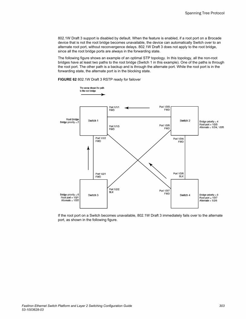
802.1W Draft 3 support is disabled by default. When the feature is enabled, if a root port on a Brocadedevice that is not the root bridge becomes unavailable, the device can automatically Switch over to analternate root port, without reconvergence delays. 802.1W Draft 3 does not apply to the root bridge,since all the root bridge ports are always in the forwarding state.
The following figure shows an example of an optimal STP topology. In this topology, all the non-rootbridges have at least two paths to the root bridge (Switch 1 in this example). One of the paths is throughthe root port. The other path is a backup and is through the alternate port. While the root port is in theforwarding state, the alternate port is in the blocking state.
FIGURE 62 802.1W Draft 3 RSTP ready for failover
If the root port on a Switch becomes unavailable, 802.1W Draft 3 immediately fails over to the alternateport, as shown in the following figure.
Spanning Tree Protocol
FastIron Ethernet Switch Platform and Layer 2 Switching Configuration Guide 30353-1003628-03
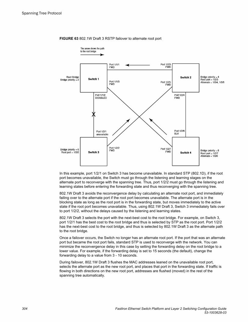
FIGURE 63 802.1W Draft 3 RSTP failover to alternate root port
In this example, port 1/2/1 on Switch 3 has become unavailable. In standard STP (802.1D), if the rootport becomes unavailable, the Switch must go through the listening and learning stages on thealternate port to reconverge with the spanning tree. Thus, port 1/2/2 must go through the listening andlearning states before entering the forwarding state and thus reconverging with the spanning tree.
802.1W Draft 3 avoids the reconvergence delay by calculating an alternate root port, and immediatelyfailing over to the alternate port if the root port becomes unavailable. The alternate port is in theblocking state as long as the root port is in the forwarding state, but moves immediately to the activestate if the root port becomes unavailable. Thus, using 802.1W Draft 3, Switch 3 immediately fails overto port 1/2/2, without the delays caused by the listening and learning states.
802.1W Draft 3 selects the port with the next-best cost to the root bridge. For example, on Switch 3,port 1/2/1 has the best cost to the root bridge and thus is selected by STP as the root port. Port 1/2/2has the next-best cost to the root bridge, and thus is selected by 802.1W Draft 3 as the alternate pathto the root bridge.
Once a failover occurs, the Switch no longer has an alternate root port. If the port that was an alternateport but became the root port fails, standard STP is used to reconverge with the network. You canminimize the reconvergence delay in this case by setting the forwarding delay on the root bridge to alower value. For example, if the forwarding delay is set to 15 seconds (the default), change theforwarding delay to a value from 3 - 10 seconds.
During failover, 802.1W Draft 3 flushes the MAC addresses leaned on the unavailable root port,selects the alternate port as the new root port, and places that port in the forwarding state. If traffic isflowing in both directions on the new root port, addresses are flushed (moved) in the rest of thespanning tree automatically.
Spanning Tree Protocol
304 FastIron Ethernet Switch Platform and Layer 2 Switching Configuration Guide53-1003628-03
Spanning tree reconvergence time
Spanning tree reconvergence using 802.1W Draft 3 can occur within one second.
After the spanning tree reconverges following the topology change, traffic also must reconverge on allthe bridges attached to the spanning tree. This is true regardless of whether 802.1W Draft 3 or standardSTP is used to reconverge the spanning tree.
Traffic reconvergence happens after the spanning tree reconvergence, and is achieved by flushing theLayer 2 information on the bridges:
• Following 802.1W Draft 3 reconvergence of the spanning tree, traffic reconvergence occurs in thetime it takes for the bridge to detect the link changes plus the STP maximum age set on the bridge.
• If standard STP reconvergence occurs instead, traffic reconvergence takes two times the forwarddelay plus the maximum age.
NOTE802.1W Draft 3 does not apply when a failed root port comes back up. When this happens, standardSTP is used.
802.1W configuration considerations
802.1W Draft 3 is disabled by default. To ensure optimal performance of the feature before you enableit,do the following:
• Configure the bridge priorities so that the root bridge is one that supports 802.1W Draft 3. (Use aBrocade device or third-party device that supports 802.1W Draft 3.)
• Change the forwarding delay on the root bridge to a value lower than the default 15 seconds.Brocade recommends a value from 3 - 10 seconds. The lower forwarding delay helps reducereconvergence delays in cases where 802.1W Draft 3 is not applicable, such as when a failed rootport comes back up.
• Configure the bridge priorities and root port costs so that each device has an active path to the rootbridge if its root port becomes unavailable. For example, port 1/2/2 is connected to port 1/2/5 onSwitch 2, which has the second most favorable bridge priority in the spanning tree.
NOTEIf reconvergence involves changing the state of a root port on a bridge that supports 802.1D STP butnot 802.1W Draft 3, then reconvergence still requires the amount of time it takes for the ports on the802.1D bridge to change state to forwarding (as needed), and receive BPDUs from the root bridge forthe new topology.
Enabling 802.1W Draft 3
802.1W Draft 3 is disabled by default. The procedure for enabling the feature differs depending onwhether single STP is enabled on the device.
NOTESTP must be enabled before you can enable 802.1W Draft 3.
Spanning tree reconvergence time
FastIron Ethernet Switch Platform and Layer 2 Switching Configuration Guide 30553-1003628-03

Enabling 802.1W Draft 3 when single STP is not enabled
By default, each port-based VLAN on the device has its own spanning tree. To enable 802.1W Draft 3in a port-based VLAN, enter commands such as the following.
device(config)#vlan 10device(config-vlan-10)#spanning-tree rstpSyntax: [no] spanning-tree rstp
This command enables 802.1W Draft 3. You must enter the command separately in each port-basedVLAN in which you want to run 802.1W Draft 3.
NOTEThis command does not also enable STP. To enable STP, first enter the spanning-tree commandwithout the rstp parameter. After you enable STP, enter the spanning-tree rstp command to enable802.1W Draft 3.
To disable 802.1W Draft 3, enter the following command.
device(config-vlan-10)#no spanning-tree rstp
Enabling 802.1W Draft 3 when single STP is enabled
To enable 802.1W Draft 3 on a device that is running single STP, enter the following command at theglobal CONFIG level of the CLI.
device(config)#spanning-tree single rstpSyntax: [no] spanning-tree single rstp
This command enables 802.1W Draft 3 on the whole device.
NOTEThis command does not also enable single STP. To enable single STP, first enter the spanning-treesingle command without the rstp parameter. After you enable single STP, enter the spanning-treesingle rstp command to enable 802.1W Draft 3.
To disable 802.1W Draft 3 on a device that is running single STP, enter the following command.
device(config)#no spanning-tree single rstp
Single Spanning Tree (SSTP)By default, each port-based VLAN on a Brocade device runs a separate spanning tree, which you canenable or disable on an individual VLAN basis.
Alternatively, you can configure a Brocade device to run a single spanning tree across all ports andVLANs on the device. The Single STP feature (SSTP) is especially useful for connecting a Brocadedevice to third-party devices that run a single spanning tree in accordance with the 802.1Qspecification.
SSTP uses the same parameters, with the same value ranges and defaults, as the default STPsupport on Brocade devices. Refer to STP parameters and defaults on page 248.
Single Spanning Tree (SSTP)
306 FastIron Ethernet Switch Platform and Layer 2 Switching Configuration Guide53-1003628-03
SSTP defaults
SSTP is disabled by default. When you enable the feature, all VLANs on which STP is enabled becomemembers of a single spanning tree. All VLANs on which STP is disabled are excluded from the singlespanning tree.
To add a VLAN to the single spanning tree, enable STP on that VLAN.To remove a VLAN from thesingle spanning tree, disable STP on that VLAN.
When you enable SSTP, all the ports that are in port-based VLANs with STP enabled become membersof a single spanning tree domain. Thus, the ports share a single BPDU broadcast domain. The Brocadedevice places all the ports in a non-configurable VLAN, 4094, to implement the SSTP domain. However,this VLAN does not affect port membership in the port-based VLANs you have configured. Otherbroadcast traffic is still contained within the individual port-based VLANs. Therefore, you can use SSTPwhile still using your existing VLAN configurations without changing your network. In addition, SSTPdoes not affect 802.1Q tagging. Tagged and untagged ports alike can be members of the singlespanning tree domain.
NOTEWhen SSTP is enabled, the BPDUs on tagged ports go out untagged.
If you disable SSTP, all VLANs that were members of the single spanning tree run MSTP instead. InMSTP, each VLAN has its own spanning tree. VLANs that were not members of the single spanningtree were not enabled for STP. Therefore, STP remains disabled on those VLANs.
Enabling SSTP
To enable SSTP, use one of the following methods.
NOTEIf the device has only one port-based VLAN (the default VLAN), then the device is already running asingle instance of STP. In this case, you do not need to enable SSTP. You need to enable SSTP only ifthe device contains more than one port-based VLAN and you want all the ports to be in the same STPbroadcast domain.
To configure the Brocade device to run a single spanning tree, enter the following command at theglobal CONFIG level.
device(config)#spanning-tree single
NOTEIf the device has only one port-based VLAN, the CLI command for enabling SSTP is not listed in theCLI. The command is listed only if you have configured a port-based VLAN.
To change a global STP parameter, enter a command such as the following at the global CONFIG level.
device(config)# spanning-tree single priority 2This command changes the STP priority for all ports to 2.
To change an STP parameter for a specific port, enter commands such as the following.
device(config) spanning-tree single ethernet 1 priority 10
SSTP defaults
FastIron Ethernet Switch Platform and Layer 2 Switching Configuration Guide 30753-1003628-03
The commands shown above override the global setting for STP priority and set the priority to 10 forport 1/1.
Here is the syntax for the global STP parameters.
Syntax: [no] spanning-tree single [ forward-delay value] [hello-time value] | [maximum-age time] |[priority value]
Here is the syntax for the STP port parameters.
Syntax: [no] spanning-tree single [ ethernet port path-cost value | priority value]
NOTEBoth commands listed above are entered at the global CONFIG level.
Displaying SSTP information
To verify that SSTP is in effect, enter the following commands at any level of the CLI.
device#show spanSyntax: show span [ vlan vlan-id] | [pvst-mode] | [num] | [detail [vlan vlan-id [ethernet port] | num]]
The vlan vlan-id parameter displays STP information for the specified port-based VLAN.
The pvst-mode parameter displays STP information for the device Per VLAN Spanning Tree (PVST+)compatibility configuration. Refer to PVST/PVST+ compatibility on page 312.
The num parameter displays only the entries after the number you specify. For example, on a devicewith three port-based VLANs, if you enter 1, then information for the second and third VLANs isdisplayed, but information for the first VLAN is not displayed. Information is displayed according toVLAN number, in ascending order. The entry number is not the same as the VLAN number. Forexample, if you have port-based VLANs 1, 10, and 2024, then the command output has three STPentries. To display information for VLANs 10 and 2024 only, enter show span 1 .
The detail parameter and its additional optional parameters display detailed information for individualports. Refer to Displaying detailed STP information for each interface on page 257.
STP per VLAN groupSTP per VLAN group is an STP enhancement that provides scalability while overcoming the limitationsof the following scalability alternatives:
• Standard STP - You can configure up to 254 instances of standard STP on a Brocade device. It ispossible to need more instances of STP than this in large configurations. Using STP per VLANgroup, you can aggregate STP instances.
• Single STP - Single STP allows all the VLANs to run STP, but each VLAN runs the same instanceof STP, resulting in numerous blocked ports that do not pass any Layer 2 traffic. STP per VLANgroup uses all available links by load balancing traffic for different instances of STP on differentports. A port that blocks traffic for one spanning tree forwards traffic for another spanning tree.
STP per VLAN group allows you to group VLANs and apply the same STP parameter settings to allthe VLANs in the group. The following figure shows an example of a STP per VLAN groupimplementation.
Displaying SSTP information
308 FastIron Ethernet Switch Platform and Layer 2 Switching Configuration Guide53-1003628-03
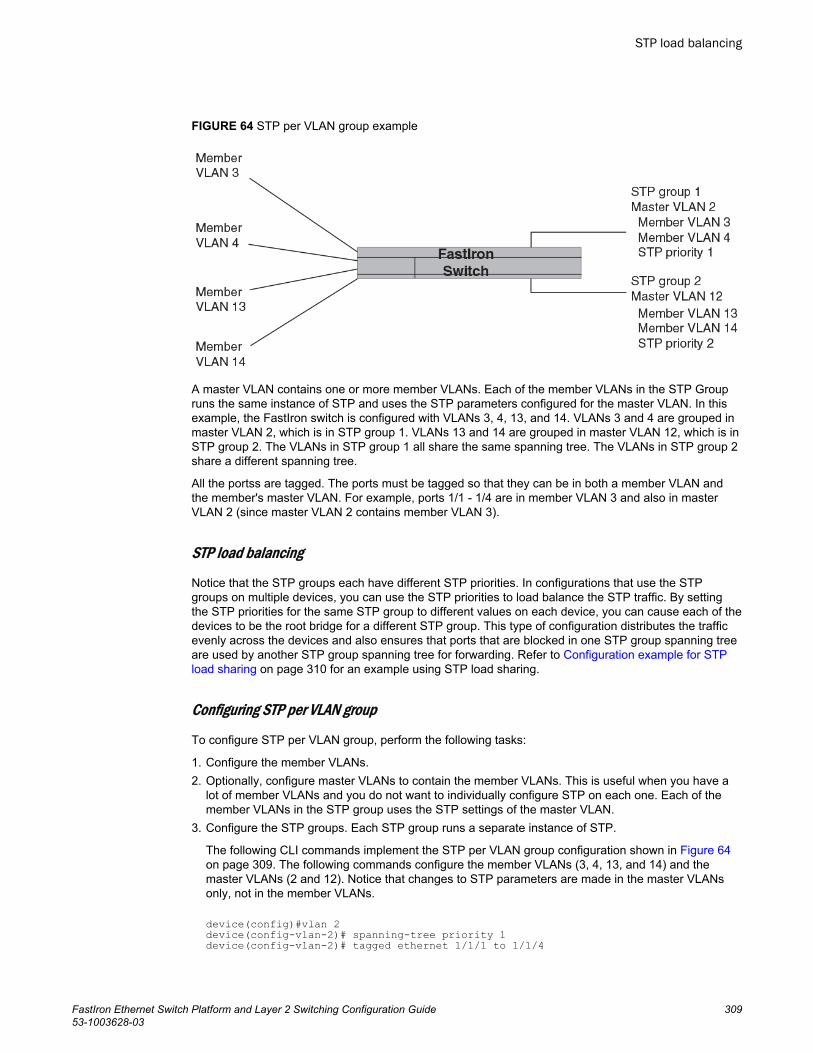
FIGURE 64 STP per VLAN group example
A master VLAN contains one or more member VLANs. Each of the member VLANs in the STP Groupruns the same instance of STP and uses the STP parameters configured for the master VLAN. In thisexample, the FastIron switch is configured with VLANs 3, 4, 13, and 14. VLANs 3 and 4 are grouped inmaster VLAN 2, which is in STP group 1. VLANs 13 and 14 are grouped in master VLAN 12, which is inSTP group 2. The VLANs in STP group 1 all share the same spanning tree. The VLANs in STP group 2share a different spanning tree.
All the portss are tagged. The ports must be tagged so that they can be in both a member VLAN andthe member's master VLAN. For example, ports 1/1 - 1/4 are in member VLAN 3 and also in masterVLAN 2 (since master VLAN 2 contains member VLAN 3).
STP load balancing
Notice that the STP groups each have different STP priorities. In configurations that use the STPgroups on multiple devices, you can use the STP priorities to load balance the STP traffic. By settingthe STP priorities for the same STP group to different values on each device, you can cause each of thedevices to be the root bridge for a different STP group. This type of configuration distributes the trafficevenly across the devices and also ensures that ports that are blocked in one STP group spanning treeare used by another STP group spanning tree for forwarding. Refer to Configuration example for STPload sharing on page 310 for an example using STP load sharing.
Configuring STP per VLAN group
To configure STP per VLAN group, perform the following tasks:
1. Configure the member VLANs.2. Optionally, configure master VLANs to contain the member VLANs. This is useful when you have a
lot of member VLANs and you do not want to individually configure STP on each one. Each of themember VLANs in the STP group uses the STP settings of the master VLAN.
3. Configure the STP groups. Each STP group runs a separate instance of STP.
The following CLI commands implement the STP per VLAN group configuration shown in Figure 64on page 309. The following commands configure the member VLANs (3, 4, 13, and 14) and themaster VLANs (2 and 12). Notice that changes to STP parameters are made in the master VLANsonly, not in the member VLANs.
device(config)#vlan 2device(config-vlan-2)# spanning-tree priority 1device(config-vlan-2)# tagged ethernet 1/1/1 to 1/1/4
STP load balancing
FastIron Ethernet Switch Platform and Layer 2 Switching Configuration Guide 30953-1003628-03
device(config-vlan-2)# vlan 3device(config-vlan-3)# tagged ethernet 1/1/1 to 1/1/4device(config-vlan-3)# vlan 4device(config-vlan-4)# tagged ethernet 1/1/1 to 1/1/4device(config-vlan-4)# vlan 12device(config-vlan-12)# spanning-tree priority 2device(config-vlan-12)# tagged ethernet 1/1/1 to 1/1/4device(config-vlan-12)# vlan 13device(config-vlan-13)# tagged ethernet 1/11/ to 1/1/4device(config-vlan-13)# vlan 14device(config-vlan-14)# tagged ethernet 1/1/1 to 1/1/4device(config-vlan-14)# exitThe following commands configure the STP groups.
device(config)#stp-group 1device(config-stp-group-1)# master-vlan 2device(config-stp-group-1)# member-vlan 3 to 4device(config-stp-group-1)# exitdevice(config)#stp-group 2device(config-stp-group-2)# master-vlan 12device(config-stp-group-2)# member-vlan 13 to 14Syntax: [no] stp-group num
This command changes the CLI to the STP group configuration level. The following commands arevalid at this level. The num parameter specifies the STP group ID and can be from 1 - 32.
Syntax: [no] master-vlan num
This command adds a master VLAN to the STP group. The master VLAN contains the STP settingsfor all the VLANs in the STP per VLAN group. The num parameter specifies the VLAN ID. An STPgroup can contain one master VLAN.
If you delete the master VLAN from an STP group, the software automatically assigns the firstmember VLAN in the group to be the new master VLAN for the group.
Syntax: [no] member-vlan num [ to num]
This command adds additional VLANs to the STP group. These VLANs also inherit the STPsettings of the master VLAN in the group.
Syntax: [no] member-group num
This command adds a member group (a VLAN group) to the STP group. All the VLANs in themember group inherit the STP settings of the master VLAN in the group. The num parameterspecifies the VLAN group ID.
NOTEThis command is optional and is not used in the example above. For an example of this command,refer to Configuration example for STP load sharing on page 310.
Configuration example for STP load sharing
The following figure shows another example of a STP per VLAN group implementation.
Configuration example for STP load sharing
310 FastIron Ethernet Switch Platform and Layer 2 Switching Configuration Guide53-1003628-03
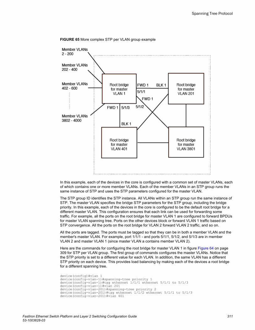
FIGURE 65 More complex STP per VLAN group example
In this example, each of the devices in the core is configured with a common set of master VLANs, eachof which contains one or more member VLANs. Each of the member VLANs in an STP group runs thesame instance of STP and uses the STP parameters configured for the master VLAN.
The STP group ID identifies the STP instance. All VLANs within an STP group run the same instance ofSTP. The master VLAN specifies the bridge STP parameters for the STP group, including the bridgepriority. In this example, each of the devices in the core is configured to be the default root bridge for adifferent master VLAN. This configuration ensures that each link can be used for forwarding sometraffic. For example, all the ports on the root bridge for master VLAN 1 are configured to forward BPDUsfor master VLAN spanning tree. Ports on the other devices block or forward VLAN 1 traffic based onSTP convergence. All the ports on the root bridge for VLAN 2 forward VLAN 2 traffic, and so on.
All the ports are tagged. The ports must be tagged so that they can be in both a member VLAN and themember's master VLAN. For example, port 1/1/1 - and ports 5/1/1, 5/1/2, and 5/1/3 are in memberVLAN 2 and master VLAN 1 (since master VLAN a contains member VLAN 2).
Here are the commands for configuring the root bridge for master VLAN 1 in figure Figure 64 on page309 for STP per VLAN group. The first group of commands configures the master VLANs. Notice thatthe STP priority is set to a different value for each VLAN. In addition, the same VLAN has a differentSTP priority on each device. This provides load balancing by making each of the devices a root bridgefor a different spanning tree.
device(config)#vlan 1device(config-vlan-1)#spanning-tree priority 1device(config-vlan-1)#tag ethernet 1/1/1 ethernet 5/1/1 to 5/1/3device(config-vlan-1)#vlan 201device(config-vlan-201)#spanning-tree priority 2device(config-vlan-201)#tag ethernet 1/1/2 ethernet 5/1/1 to 5/1/3device(config-vlan-201)#vlan 401
Spanning Tree Protocol
FastIron Ethernet Switch Platform and Layer 2 Switching Configuration Guide 31153-1003628-03
device(config-vlan-401)#spanning-tree priority 3device(config-vlan-401)#tag ethernet 1/1/3 ethernet 5/1/1 to 5/1/3...device(config-vlan-3601)#vlan 3801device(config-vlan-3801)#spanning-tree priority 20device(config-vlan-3801)#tag ethernet 1/1/20 ethernet 5/1/1 to 5/1/3device(config-vlan-3801)#exitThe next group of commands configures VLAN groups for the member VLANs. Notice that the VLANgroups do not contain the VLAN numbers assigned to the master VLANs. Also notice that no STPparameters are configured for the groups of member VLANs. Each group of member VLANs willinherit its STP settings from its master VLAN.
Set the bridge priority for each master VLAN to the highest priority (1) on one of the devices in theSTP per VLAN group configuration. By setting the bridge priority to the highest priority, you make thedevice the default root bridge for the spanning tree. To ensure STP load balancing, make each of thedevices the default root bridge for a different master VLAN.
device(config)#vlan-group 1 vlan 2 to 200device(config-vlan-group-1)#tag ethernet 1/1/1 ethernet 5/1/1 to 5/1/3device(config-vlan-group-1)#vlan-group 2 vlan 202 to 400device(config-vlan-group-2)#tag ethernet 1/1/2 ethernet 5/1/1 to 5/1/3device(config-vlan-group-2)#vlan-group 3 vlan 402 to 600device(config-vlan-group-2)#tag ethernet 1/1/3 ethernet 5/1/1 to 5/1/3...device(config-vlan-group-19)#vlan-group 20 vlan 3082 to 3282device(config-vlan-group-20)#tag ethernet 1/1/20 ethernet 5/1/1 to 5/1/3device(config-vlan-group-20)#exitThe following group of commands configures the STP groups. Each STP group in this configurationcontains one master VLAN, which contains a VLAN group. This example shows that an STP groupalso can contain additional VLANs (VLANs not configured in a VLAN group).
device(config)#stp-group 1device(config-stp-group-1)#master-vlan 1device(config-stp-group-1)#member-group 1device(config-stp-group-1)#member-vlan 4001 4004 to 4010device(config-stp-group-1)#stp-group 2device(config-stp-group-2)#master-vlan 201device(config-stp-group-2)#member-group 2device(config-stp-group-2)#member-vlan 4002 4003 4011 to 4015device(config-stp-group-2)#stp-group 3device(config-stp-group-3)#master-vlan 401device(config-stp-group-3)#member-group 3...device(config-stp-group-19)#stp-group 20device(config-stp-group-20)#master-vlan 3081device(config-stp-group-20)#member-group 20
PVST/PVST+ compatibilityThe FastIron family of switches support Cisco's Per VLAN Spanning Tree plus (PVST+), by allowingthe device to run multiple spanning trees (MSTP) while also interoperating with IEEE 802.1Q devices1.
NOTEBrocade ports automatically detect PVST+ BPDUs and enable support for the BPDUs once detected.You do not need to perform any configuration steps to enable PVST+ support. However, to support theIEEE 802.1Q BPDUs, you might need to enable dual-mode support.
Support for Cisco's Per VLAN Spanning Tree plus (PVST+), allows a Brocade device to run multiplespanning trees (MSTP) while also interoperating with IEEE 802.1Q devices. Brocade portsautomatically detect PVST+ BPDUs and enable support for the BPDUs once detected. The
PVST/PVST+ compatibility
312 FastIron Ethernet Switch Platform and Layer 2 Switching Configuration Guide53-1003628-03
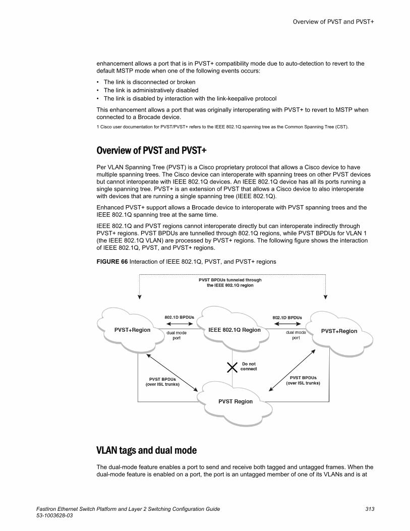
enhancement allows a port that is in PVST+ compatibility mode due to auto-detection to revert to thedefault MSTP mode when one of the following events occurs:
• The link is disconnected or broken• The link is administratively disabled• The link is disabled by interaction with the link-keepalive protocol
This enhancement allows a port that was originally interoperating with PVST+ to revert to MSTP whenconnected to a Brocade device.1 Cisco user documentation for PVST/PVST+ refers to the IEEE 802.1Q spanning tree as the Common Spanning Tree (CST).
Overview of PVST and PVST+Per VLAN Spanning Tree (PVST) is a Cisco proprietary protocol that allows a Cisco device to havemultiple spanning trees. The Cisco device can interoperate with spanning trees on other PVST devicesbut cannot interoperate with IEEE 802.1Q devices. An IEEE 802.1Q device has all its ports running asingle spanning tree. PVST+ is an extension of PVST that allows a Cisco device to also interoperatewith devices that are running a single spanning tree (IEEE 802.1Q).
Enhanced PVST+ support allows a Brocade device to interoperate with PVST spanning trees and theIEEE 802.1Q spanning tree at the same time.
IEEE 802.1Q and PVST regions cannot interoperate directly but can interoperate indirectly throughPVST+ regions. PVST BPDUs are tunnelled through 802.1Q regions, while PVST BPDUs for VLAN 1(the IEEE 802.1Q VLAN) are processed by PVST+ regions. The following figure shows the interactionof IEEE 802.1Q, PVST, and PVST+ regions.
FIGURE 66 Interaction of IEEE 802.1Q, PVST, and PVST+ regions
VLAN tags and dual modeThe dual-mode feature enables a port to send and receive both tagged and untagged frames. When thedual-mode feature is enabled on a port, the port is an untagged member of one of its VLANs and is at
Overview of PVST and PVST+
FastIron Ethernet Switch Platform and Layer 2 Switching Configuration Guide 31353-1003628-03
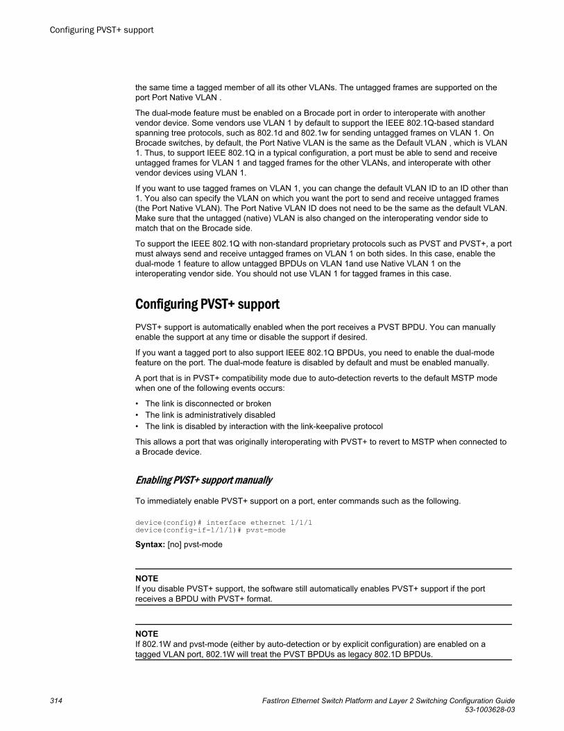
the same time a tagged member of all its other VLANs. The untagged frames are supported on theport Port Native VLAN .
The dual-mode feature must be enabled on a Brocade port in order to interoperate with anothervendor device. Some vendors use VLAN 1 by default to support the IEEE 802.1Q-based standardspanning tree protocols, such as 802.1d and 802.1w for sending untagged frames on VLAN 1. OnBrocade switches, by default, the Port Native VLAN is the same as the Default VLAN , which is VLAN1. Thus, to support IEEE 802.1Q in a typical configuration, a port must be able to send and receiveuntagged frames for VLAN 1 and tagged frames for the other VLANs, and interoperate with othervendor devices using VLAN 1.
If you want to use tagged frames on VLAN 1, you can change the default VLAN ID to an ID other than1. You also can specify the VLAN on which you want the port to send and receive untagged frames(the Port Native VLAN). The Port Native VLAN ID does not need to be the same as the default VLAN.Make sure that the untagged (native) VLAN is also changed on the interoperating vendor side tomatch that on the Brocade side.
To support the IEEE 802.1Q with non-standard proprietary protocols such as PVST and PVST+, a portmust always send and receive untagged frames on VLAN 1 on both sides. In this case, enable thedual-mode 1 feature to allow untagged BPDUs on VLAN 1and use Native VLAN 1 on theinteroperating vendor side. You should not use VLAN 1 for tagged frames in this case.
Configuring PVST+ supportPVST+ support is automatically enabled when the port receives a PVST BPDU. You can manuallyenable the support at any time or disable the support if desired.
If you want a tagged port to also support IEEE 802.1Q BPDUs, you need to enable the dual-modefeature on the port. The dual-mode feature is disabled by default and must be enabled manually.
A port that is in PVST+ compatibility mode due to auto-detection reverts to the default MSTP modewhen one of the following events occurs:
• The link is disconnected or broken• The link is administratively disabled• The link is disabled by interaction with the link-keepalive protocol
This allows a port that was originally interoperating with PVST+ to revert to MSTP when connected toa Brocade device.
Enabling PVST+ support manually
To immediately enable PVST+ support on a port, enter commands such as the following.
device(config)# interface ethernet 1/1/1device(config-if-1/1/1)# pvst-modeSyntax: [no] pvst-mode
NOTEIf you disable PVST+ support, the software still automatically enables PVST+ support if the portreceives a BPDU with PVST+ format.
NOTEIf 802.1W and pvst-mode (either by auto-detection or by explicit configuration) are enabled on atagged VLAN port, 802.1W will treat the PVST BPDUs as legacy 802.1D BPDUs.
Configuring PVST+ support
314 FastIron Ethernet Switch Platform and Layer 2 Switching Configuration Guide53-1003628-03
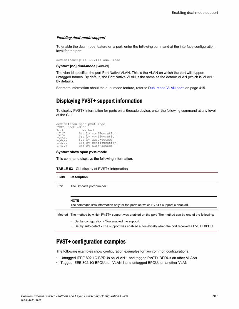
Enabling dual-mode support
To enable the dual-mode feature on a port, enter the following command at the interface configurationlevel for the port.
device(config-if-1/1/1)# dual-modeSyntax: [no] dual-mode [vlan-id]
The vlan-id specifies the port Port Native VLAN. This is the VLAN on which the port will supportuntagged frames. By default, the Port Native VLAN is the same as the default VLAN (which is VLAN 1by default).
For more information about the dual-mode feature, refer to Dual-mode VLAN ports on page 415.
Displaying PVST+ support informationTo display PVST+ information for ports on a Brocade device, enter the following command at any levelof the CLI.
device#show span pvst-modePVST+ Enabled on: Port Method 1/1/1 Set by configuration 1/1/2 Set by configuration1/2/10 Set by auto-detect 1/3/12 Set by configuration1/4/24 Set by auto-detectSyntax: show span pvst-mode
This command displays the following information.
CLI display of PVST+ information TABLE 53
Field Description
Port The Brocade port number.
NOTEThe command lists information only for the ports on which PVST+ support is enabled.
Method The method by which PVST+ support was enabled on the port. The method can be one of the following:
• Set by configuration - You enabled the support.• Set by auto-detect - The support was enabled automatically when the port received a PVST+ BPDU.
PVST+ configuration examplesThe following examples show configuration examples for two common configurations:
• Untagged IEEE 802.1Q BPDUs on VLAN 1 and tagged PVST+ BPDUs on other VLANs• Tagged IEEE 802.1Q BPDUs on VLAN 1 and untagged BPDUs on another VLAN
Enabling dual-mode support
FastIron Ethernet Switch Platform and Layer 2 Switching Configuration Guide 31553-1003628-03
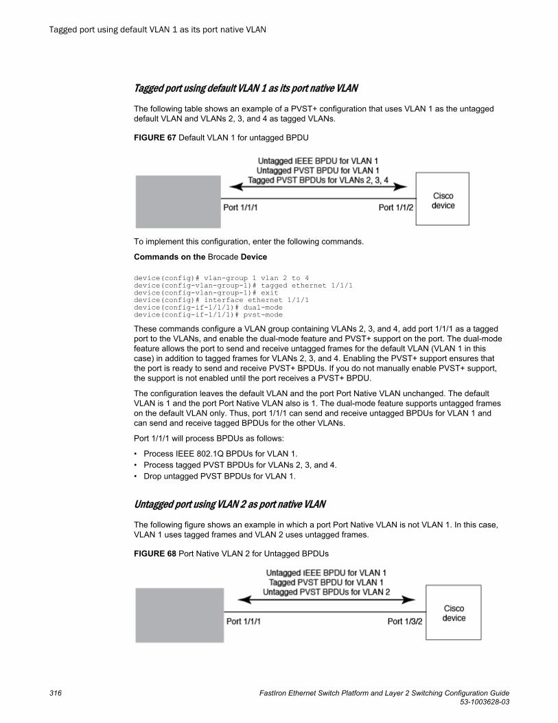
Tagged port using default VLAN 1 as its port native VLAN
The following table shows an example of a PVST+ configuration that uses VLAN 1 as the untaggeddefault VLAN and VLANs 2, 3, and 4 as tagged VLANs.
FIGURE 67 Default VLAN 1 for untagged BPDU
To implement this configuration, enter the following commands.
Commands on the Brocade Device
device(config)# vlan-group 1 vlan 2 to 4device(config-vlan-group-1)# tagged ethernet 1/1/1device(config-vlan-group-1)# exitdevice(config)# interface ethernet 1/1/1device(config-if-1/1/1)# dual-modedevice(config-if-1/1/1)# pvst-modeThese commands configure a VLAN group containing VLANs 2, 3, and 4, add port 1/1/1 as a taggedport to the VLANs, and enable the dual-mode feature and PVST+ support on the port. The dual-modefeature allows the port to send and receive untagged frames for the default VLAN (VLAN 1 in thiscase) in addition to tagged frames for VLANs 2, 3, and 4. Enabling the PVST+ support ensures thatthe port is ready to send and receive PVST+ BPDUs. If you do not manually enable PVST+ support,the support is not enabled until the port receives a PVST+ BPDU.
The configuration leaves the default VLAN and the port Port Native VLAN unchanged. The defaultVLAN is 1 and the port Port Native VLAN also is 1. The dual-mode feature supports untagged frameson the default VLAN only. Thus, port 1/1/1 can send and receive untagged BPDUs for VLAN 1 andcan send and receive tagged BPDUs for the other VLANs.
Port 1/1/1 will process BPDUs as follows:
• Process IEEE 802.1Q BPDUs for VLAN 1.• Process tagged PVST BPDUs for VLANs 2, 3, and 4.• Drop untagged PVST BPDUs for VLAN 1.
Untagged port using VLAN 2 as port native VLAN
The following figure shows an example in which a port Port Native VLAN is not VLAN 1. In this case,VLAN 1 uses tagged frames and VLAN 2 uses untagged frames.
FIGURE 68 Port Native VLAN 2 for Untagged BPDUs
Tagged port using default VLAN 1 as its port native VLAN
316 FastIron Ethernet Switch Platform and Layer 2 Switching Configuration Guide53-1003628-03
To implement this configuration, enter the following commands.
Commands on the Brocade Device
device(config)#default-vlan-id 4000device(config)#vlan 1device(config-vlan-1)#tagged ethernet 1/1/1device(config-vlan-1)#exitdevice(config)#vlan 2device(config-vlan-2)#tagged ethernet 1/1/1device(config-vlan-2)#exitdevice(config)#interface ethernet 1/1/1device(config-if-1/1/1)#dual-mode 2device(config-if-1/1/1)#pvst-modedevice(config-if-1/1/1)#exitThese commands change the default VLAN ID, configure port 1/1/1 as a tagged member of VLANs 1and 2, and enable the dual-mode feature and PVST+ support on port 1/1/1. Since VLAN 1 is tagged inthis configuration, the default VLAN ID must be changed from VLAN 1 to another VLAN ID. Changingthe default VLAN ID from 1 allows the port to process tagged frames for VLAN 1. VLAN 2 is specifiedwith the dual-mode command, which makes VLAN 2 the port Port Native VLAN. As a result, the portprocesses untagged frames and untagged PVST BPDUs on VLAN 2.
NOTEAlthough VLAN 2 becomes the port untagged VLAN, the CLI still requires that you add the port to theVLAN as a tagged port, since the port is a member of more than one VLAN.
Port 1/1 will process BPDUs as follows:
• Process IEEE 802.1Q BPDUs for VLAN 1.• Process untagged PVST BPDUs for VLAN 2.• Drop tagged PVST BPDUs for VLAN 1.
Note that when VLAN 1 is not the default VLAN, the ports must have the dual-mode feature enabled inorder to process IEEE 802.1Q BPDUs.
For example, the following configuration is incorrect.
device(config)# default-vlan-id 1000device(config)# vlan 1device(config-vlan-1)# tagged ethernet 1/1/1 to 1/1/2device(config-vlan-1)# exitdevice(config)# interface ethernet 1/1/1device(config-if-1/1/1)# pvst-modedevice(config-if-1/1/1)# exitdevice(config)# interface ethernet 1/1/2device(config-if-1/1/2)# pvst-modedevice(config-if-1/1/2)# exitIn the configuration above, all PVST BPDUs associated with VLAN 1 would be discarded. Since IEEEBPDUs associated with VLAN 1 are untagged, they are discarded because the ports in VLAN 1 aretagged. Effectively, the BPDUs are never processed by the Spanning Tree Protocol. STP assumes thatthere is no better bridge on the network and sets the ports to FORWARDING. This could cause a Layer2 loop.
The following configuration is correct.
device(config)# default-vlan-id 1000device(config)# vlan 1device(config-vlan-1)# tagged ethernet 1/1/1 to 1/1/2device(config-vlan-1)# exitdevice(config)# interface ethernet 1/1/1device(config-if-1/1/1)# pvst-modedevice(config-if-1/1/1)# dual-modedevice(config-if-1/1/1)# exitdevice(config)# interface ethernet 1/1/2device(config-if-1/1/2)# pvst-mode
Spanning Tree Protocol
FastIron Ethernet Switch Platform and Layer 2 Switching Configuration Guide 31753-1003628-03

device(config-if-1/1/2)# dual-modedevice(config-if-1/1/2)# exitSetting the ports as dual-mode ensures that the untagged IEEE 802.1Q BPDUs reach the VLAN 1instance.
PVRST compatibilityPVRST, the "rapid" version of per-VLAN spanning tree (PVST), is a Cisco proprietary protocol. PVRSTcorresponds to the Brocade full implementation of IEEE 802.1w (RSTP). Likewise, PVST, also a Ciscoproprietary protocol, corresponds to the Brocade implementation of IEEE 802.1D (STP). When aBrocade device receives PVRST BPDUs on a port configured to run 802.1w, it recognizes andprocesses these BPDUs and continues to operate in 802.1w mode.
PVRST compatibility is automatically enabled when a port receives a PVRST BPDU.
BPDU guardIn an STP environment, switches, end stations, and other Layer 2 devices use Bridge Protocol DataUnits (BPDUs) to exchange information that STP will use to determine the best path for data flow.
The BPDU guard, an enhancement to STP, removes a node that reflects BPDUs back in the network.It enforces the STP domain borders and keeps the active topology predictable by not allowing anynetwork devices behind a BPDU guard-enabled port to participate in STP.
In some instances, it is unnecessary for a connected device, such as an end station, to initiate orparticipate in an STP topology change. In this case, you can enable the STP BPDU guard feature onthe Brocade port to which the end station is connected. STP BPDU guard shuts down the port andputs it into an errdisable state. This disables the connected device's ability to initiate or participate inan STP topology. A log message is then generated for a BPDU guard violation, and a CLI message isdisplayed to warn the network administrator of a severe invalid configuration. The BPDU guard featureprovides a secure response to invalid configurations because the administrator must manually put theinterface back in service if errdisable recovery is not enabled.
NOTEBPDU guard is not supported on tagged ports. It can be configured on a tagged port, but theconfiguration will have no effect.
Enabling BPDU protection by portYou can enable STP BPDU guard on individual interfaces. The feature is disabled by default.
To enable STP BPDU guard on a specific port, enter a command such as the following.
NOTESpanning tree must be enabled on the corresponding VLAN.
device(config) interface ethernet 1/1/2device(config-if-e1000-1/1/2)# stp-bpdu-guard
PVRST compatibility
318 FastIron Ethernet Switch Platform and Layer 2 Switching Configuration Guide53-1003628-03
Syntax: [no] stp-bpd-guard
The no parameter disables the BPDU guard on this interface.
You can also use the multiple interface command to enable this feature on multiple ports at once.
device(config)# interface ethernet 1/1/1 to 1/1/9device(config-mif-1/1/1-1/1/9)# stp-bpdu-guarddevice(config-mif-1/1/1-1/1/9)#This will enable stp-bpdu-guard on ports 1/1/1 to 1/1/9
Re-enabling ports disabled by BPDU guardWhen a BPDU Guard-enabled port is disabled by BPDU Guard, the Brocade device will place the portin errdisable state and display a message on the console indicating that the port is errdisabled (refer to BPDU guard status example console messages on page 320). In addition, the show interfacecommand output will indicate that the port is errdisabled.
device#show int e 2Gigabit Ethernet2 is ERR-DISABLED (bpduguard), line protocol is downTo re-enable a port that is in errdisable state, you must first disable the port then re-enable it. Entercommands such as the following.
device(config)#int e 2device(config-if-e1000-2)#disabledevice(config-if-e1000-2)#enableIf you attempt to enable an errdisabled port without first disabling it, the following error message willappear on the console.
device(config-if-e1000-2)#enablePort 2 is errdisabled, do disable first and then enable to enable it
Displaying the BPDU guard statusTo display the BPDU guard state, enter the show running configuration or the show stp-bpdu-guardcommand.
For FastIron X Series devices, enter the stp-bpdu-guard command.
device#show stp-bpdu-guardBPDU Guard Enabled on:Interface ViolationPort 1 NoPort 2 NoPort 3 NoPort 4 NoPort 5 NoPort 6 NoPort 7 NoPort 8 NoPort 9 NoPort 10 NoPort 11 NoPort 12 YesPort 13 No
BPDU guard status example configurations
Re-enabling ports disabled by BPDU guard
FastIron Ethernet Switch Platform and Layer 2 Switching Configuration Guide 31953-1003628-03
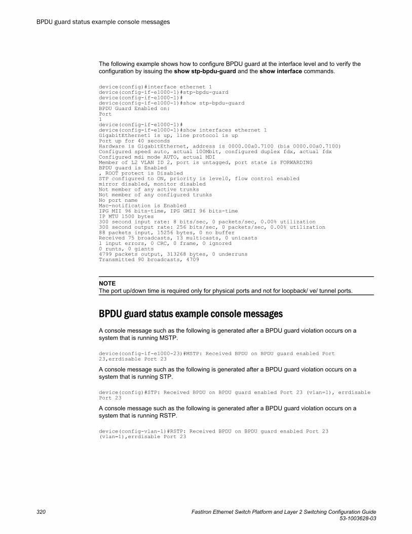
The following example shows how to configure BPDU guard at the interface level and to verify theconfiguration by issuing the show stp-bpdu-guard and the show interface commands.
device(config)#interface ethernet 1device(config-if-e1000-1)#stp-bpdu-guarddevice(config-if-e1000-1)#device(config-if-e1000-1)#show stp-bpdu-guardBPDU Guard Enabled on:Port1device(config-if-e1000-1)#device(config-if-e1000-1)#show interfaces ethernet 1GigabitEthernet1 is up, line protocol is upPort up for 40 secondsHardware is GigabitEthernet, address is 0000.00a0.7100 (bia 0000.00a0.7100)Configured speed auto, actual 100Mbit, configured duplex fdx, actual fdxConfigured mdi mode AUTO, actual MDIMember of L2 VLAN ID 2, port is untagged, port state is FORWARDINGBPDU guard is Enabled, ROOT protect is DisabledSTP configured to ON, priority is level0, flow control enabledmirror disabled, monitor disabledNot member of any active trunksNot member of any configured trunksNo port nameMac-notification is EnabledIPG MII 96 bits-time, IPG GMII 96 bits-timeIP MTU 1500 bytes300 second input rate: 8 bits/sec, 0 packets/sec, 0.00% utilization300 second output rate: 256 bits/sec, 0 packets/sec, 0.00% utilization88 packets input, 15256 bytes, 0 no bufferReceived 75 broadcasts, 13 multicasts, 0 unicasts1 input errors, 0 CRC, 0 frame, 0 ignored0 runts, 0 giants4799 packets output, 313268 bytes, 0 underrunsTransmitted 90 broadcasts, 4709
NOTEThe port up/down time is required only for physical ports and not for loopback/ ve/ tunnel ports.
BPDU guard status example console messagesA console message such as the following is generated after a BPDU guard violation occurs on asystem that is running MSTP.
device(config-if-e1000-23)#MSTP: Received BPDU on BPDU guard enabled Port 23,errdisable Port 23A console message such as the following is generated after a BPDU guard violation occurs on asystem that is running STP.
device(config)#STP: Received BPDU on BPDU guard enabled Port 23 (vlan=1), errdisable Port 23A console message such as the following is generated after a BPDU guard violation occurs on asystem that is running RSTP.
device(config-vlan-1)#RSTP: Received BPDU on BPDU guard enabled Port 23 (vlan=1),errdisable Port 23
BPDU guard status example console messages
320 FastIron Ethernet Switch Platform and Layer 2 Switching Configuration Guide53-1003628-03
Root guardThe standard STP (802.1D), RSTP (802.1W) or 802.1S does not provide any way for a networkadministrator to securely enforce the topology of a switched layer 2 network. The forwarding topology ofa switched network is calculated based on the root bridge position, along with other parameters. Thismeans any switch can be the root bridge in a network as long as it has the lowest bridge ID. Theadministrator cannot enforce the position of the root bridge. A better forwarding topology comes with therequirement to place the root bridge at a specific predetermined location. Root Guard can be used topredetermine a root bridge location and prevent rogue or unwanted switches from becoming the rootbridge.
When root guard is enabled on a port, it keeps the port in a designated role. If the port receives asuperior STP Bridge Protocol Data Units (BPDU), it puts the port into a ROOT-INCONSISTANT stateand triggers a log message and an SNMP trap. The ROOT-INCONSISTANT state is equivalent to theBLOCKING state in 802.1D and to the DISCARDING state in 802.1W. No further traffic is forwarded onthis port. This allows the bridge to prevent traffic from being forwarded on ports connected to rogue ormisconfigured STP bridges.
Once the port stops receiving superior BPDUs, root guard automatically sets the port back to learning,and eventually to a forwarding state through the spanning-tree algorithm.
Configure root guard on all ports where the root bridge should not appear. This establishes a protectivenetwork perimeter around the core bridged network, cutting it off from the user network.
NOTERoot guard may prevent network connectivity if it is improperly configured. Root guard must beconfigured on the perimeter of the network rather than the core.
NOTERoot guard is not supported when MSTP is enabled.
Enabling STP root guardAn STP root guard is configured on an interface by entering commands similar to the following.
device(config)#interface ethernet 1/1/5device(config-if-e10000-1/1/5)spanning-tree root-protectSyntax: [no] spanning-tree root-protect
Enter the no form of the command to disable STP root guard on the port.
Displaying the STP root guardTo display the STP root guard state, enter the show running configuration or the show span root-protect command.
device#show span root-protectRoot Protection Enabled on:Port 1Syntax: show span root-protect
Root guard
FastIron Ethernet Switch Platform and Layer 2 Switching Configuration Guide 32153-1003628-03
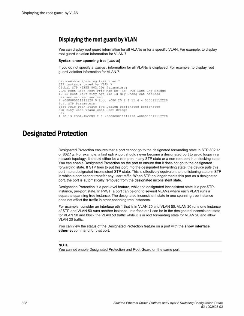
Displaying the root guard by VLANYou can display root guard information for all VLANs or for a specific VLAN. For example, to displayroot guard violation information for VLAN 7.
Syntax: show spanning-tree [vlan-id]
If you do not specify a vlan-id , information for all VLANs is displayed. For example, to display rootguard violation information for VLAN 7.
device#show spanning-tree vlan 7STP instance owned by VLAN 7Global STP (IEEE 802.1D) Parameters:VLAN Root Root Root Prio Max He- Ho- Fwd Last Chg Bridge ID ID Cost Port rity Age llo ld dly Chang cnt Address Hex sec sec sec sec sec 7 a000000011112220 0 Root a000 20 2 1 15 4 4 000011112220Port STP Parameters:Port Prio Path State Fwd Design Designated Designated Num rity Cost Trans Cost Root Bridge Hex 1 80 19 ROOT-INCONS 2 0 a000000011112220 a000000011112220
Designated Protection
Designated Protection ensures that a port cannot go to the designated forwarding state in STP 802.1dor 802.1w. For example, a fast uplink port should never become a designated port to avoid loops in anetwork topology. It should either be a root port in any STP state or a non-root port in a blocking state.You can enable Designated Protection on the port to ensure that it does not go to the designatedforwarding state. If STP tries to put this port into the designated forwarding state, the device puts thisport into a designated inconsistent STP state. This is effectively equivalent to the listening state in STPin which a port cannot transfer any user traffic. When STP no longer marks this port as a designatedport, the port is automatically removed from the designated inconsistent state.
Designation Protection is a port-level feature, while the designated inconsistent state is a per-STP-instance, per-port state. In PVST, a port can belong to several VLANs where each VLAN runs aseparate spanning tree instance. The designated inconsistent state in one spanning tree instancedoes not affect the traffic in other spanning tree instances.
For example, consider an interface eth 1 that is in VLAN 20 and VLAN 50. VLAN 20 runs one instanceof STP and VLAN 50 runs another instance. Interface eth1 can be in the designated inconsistent statefor VLAN 50 and block the VLAN 50 traffic while it is in root forwarding state for VLAN 20 and allowVLAN 20 traffic.
You can view the status of the Designated Protection feature on a port with the show interfaceethernet command for that port.
NOTEYou cannot enable Designated Protection and Root Guard on the same port.
Displaying the root guard by VLAN
322 FastIron Ethernet Switch Platform and Layer 2 Switching Configuration Guide53-1003628-03
Enabling Designated Protection on a port
To disallow the designated forwarding state on a port in STP (802.1d or 802.1w), run the spanning-tree designated-protect command in interface configuration mode for that port.
The following example shows that the designated forwarding state is disallowed on Ethernet interface1/1/1.Brocade(config)# ethernet interface 1/1/1Brocade(config-if-e1000-1/1/1)# spanning-tree designated-protect
Syslog message for a port in designated inconsistent state
The following syslog message is generated when a port is put in the designated inconsistent state.5d19h00m12s:I:STP: VLAN 100 Designated-protect port 2/1/7, inconsistent, Put into Listening state
Error disable recovery
If a BPDU Guard violation or loop detection violation occurs, or the number of inError packets exceedsthe configured threshold, or if an EFM-OAM enabled interface receives a critical event from the remotedevice, a port is placed into an error-disabled state, which is functionally equivalent to a disable state.Once in an error-disabled state, the port remains in that state until it is enabled either automatically ormanually.
Enabling an error-disabled port automaticallyTo enable a port to recover automatically from the error-disabled state after the expiry of a configurederror recovery timer, run the errdisable recovery cause command in global configuration mode.
For example, to enable error-disable recovery for BPDU guard, enter the following command:
Brocade(config)# errdisable recovery cause bpduguardSyntax: errdisable recovery cause [ bpduguard | loam-critical-event | loop-detection | packet-inerror-detect | all ]
Thebpduguard parameter allows the port to recover from the error-disabled state, if the state wascaused by a BPDU guard violation.
The all parameter allows ports to recover from an error-disabled state caused by any reason, forexample, a BPDU guard violation, due to reception of a critical event from the remote device in the caseof EFM-OAM interface, the number of inError packets exceeding the configured threshold, or a loop-detection violation.
NOTEWhen automatic recovery re-enables the port, the port is not in the error-disabled state, but it canremain down for other reasons, such as the Tx/Rx of the fibre optic not being seated properly. Thus, theport is not able to receive the signal from the other side. In this case, after the optic is inserted correctly,you should manually disable the port and then enable it.
Enabling Designated Protection on a port
FastIron Ethernet Switch Platform and Layer 2 Switching Configuration Guide 32353-1003628-03
Enabling an error-disabled port manually
To enable an error-disabled port manually, you must first run the disable command and then theenable command in interface configuration mode to disable the port and then enable the portrespectively.
Setting the recovery intervalThe errdisable recovery interval command allows you to configure a timeout for ports in the error-disabled state, after which the ports are re-enabled automatically. To set the error-disabled recoverytimeout interval, enter the following command:
Brocade(config)# errdisable recovery interval 20Syntax: [no] errdisable recovery interval seconds
The seconds variable allows you to set the timeout value for the recovery mechanism when the port isin an errdisabled state. Once this timeout value expires, the ports are automatically re-enabled. Validvalues are from 10 through 65535 seconds.
Displaying the error disable recovery state by interfaceThe port status of errdisabled displays in the output of the show interface and the show interfacebrief commands. In this example, errdisable is enabled on interface ethernet 1 and errdisable isenabled because of a BPDU guard violation.
device#show interfaces ethernet 1GigabitEthernet1 is ERR-DISABLED (bpduguard), line protocol is downBPDU guard is Enabled, ROOT protect is DisabledPort down for 2 hours 45 minutes 10 secondsHardware is GigabitEthernet, address is 0000.00a0.7100 (bia 0000.00a0.7100)Configured speed auto, actual unknown, configured duplex fdx, actual unknownConfigured mdi mode AUTO, actual unknownMember of L2 VLAN ID 2, port is untagged, port state is DISABLEDSTP configured to ON, priority is level0, flow control enabledmirror disabled, monitor disabledNot member of any active trunksNot member of any configured trunksNo port nameIPG MII 96 bits-time, IPG GMII 96 bits-timeIP MTU 1500 bytes300 second input rate: 0 bits/sec, 0 packets/sec, 0.00% utilization300 second output rate: 0 bits/sec, 0 packets/sec, 0.00% utilization145 packets input, 23561 bytes, 0 no bufferReceived 124 broadcasts, 21 multicasts, 0 unicasts1 input errors, 0 CRC, 0 frame, 0 ignored0 runts, 0 giants5067 packets output, 330420 bytes, 0 underrunsTransmitted 90 broadcasts, 4977 multicasts, 0 unicasts0 output errors, 0 collisions
Displaying the recovery state for all conditionsUse the show errdisable recovery command to display all the default error disable recovery state forall possible conditions. In this example, port 6 is undergoing a recovery.
device#show errdisable recoveryErrDisable Reason Timer Status --------------------------------------
Enabling an error-disabled port manually
324 FastIron Ethernet Switch Platform and Layer 2 Switching Configuration Guide53-1003628-03
all reason Disabledbpduguard EnabledTimeout Value: 300 secondsInterface that will be enabled at the next timeout:Interface Errdisable reason Time left (sec)-------------- ----------------- ---------------Port 6 bpduguard 297Syntax: show errdisable recovery
Displaying the recovery state by port number and causeTo see which ports are under an errdisabled state, use the show errdisable summary command. Thiscommand not only shows the port number, but also displays the reason why the port is in an errdisablestate and the method used to recover the port. In this example, port 6 is errdisabled for a BPDU guardviolation.
device#show errdisable summaryPort 6 ERR_DiSABLED for bpduguardSyntax: show errdisable summary
Errdisable Syslog messagesWhen the system places a port into an errdisabled state for BPDU guard, a log message is generated.When the errdisable recovery timer expires, a log message is also generated.
A Syslog message such as the following is generated after a port is placed into an errdisable state forBPDU guard.
STP: VLAN 50 BPDU-guard port 3 detect (Received BPDU), putting into err-disable stateA Syslog message such as the following is generated after the recovery timer expires.
ERR_DISABLE: Interface ethernet 3, err-disable recovery timeout
802.1s Multiple Spanning Tree ProtocolMultiple Spanning Tree Protocol (MSTP), as defined in IEEE 802.1s, allows multiple VLANs to bemanaged by a single STP instance and supports per-VLAN STP. As a result, several VLANs can bemapped to a reduced number of spanning-tree instances. This ensures loop-free topology for one ormore VLANs that have the similar layer-2 topology. The Brocade implementation supports up to 16spanning tree instances in an MSTP enabled bridge which means that it can support up to 16 differentLayer 2 topologies. The spanning tree algorithm used by MSTP is RSTP which provides quickconvergence.
Multiple spanning-tree regionsUsing MSTP, the entire network runs a common instance of RSTP. Within that common instance, oneor more VLANs can be individually configured into distinct regions. The entire network runs the commonspanning tree instance (CST) and the regions run a local instance. The local instance is known asInternal Spanning Tree (IST). The CST treats each instance of IST as a single bridge. Consequently,ports are blocked to prevent loops that might occur within an IST and also throughout the CST. With theexception of the provisions for multiple instances, MSTP operates exactly like RSTP.
Displaying the recovery state by port number and cause
FastIron Ethernet Switch Platform and Layer 2 Switching Configuration Guide 32553-1003628-03
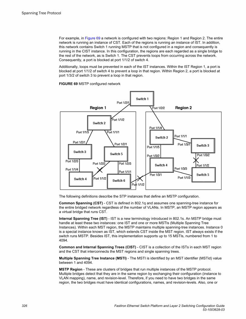
For example, in Figure 69 a network is configured with two regions: Region 1 and Region 2. The entirenetwork is running an instance of CST. Each of the regions is running an instance of IST. In addition,this network contains Switch 1 running MSTP that is not configured in a region and consequently isrunning in the CIST instance. In this configuration, the regions are each regarded as a single bridge tothe rest of the network, as is Switch 1. The CST prevents loops from occurring across the network.Consequently, a port is blocked at port 1/1/2 of switch 4.
Additionally, loops must be prevented in each of the IST instances. Within the IST Region 1, a port isblocked at port 1/1/2 of switch 4 to prevent a loop in that region. Within Region 2, a port is blocked atport 1/3/2 of switch 3 to prevent a loop in that region.
FIGURE 69 MSTP configured network
The following definitions describe the STP instances that define an MSTP configuration.
Common Spanning (CST) - CST is defined in 802.1q and assumes one spanning-tree instance forthe entire bridged network regardless of the number of VLANs. In MSTP, an MSTP region appears asa virtual bridge that runs CST.
Internal Spanning Tree (IST) - IST is a new terminology introduced in 802.1s. An MSTP bridge musthandle at least these two instances: one IST and one or more MSTIs (Multiple Spanning TreeInstances). Within each MST region, the MSTP maintains multiple spanning-tree instances. Instance 0is a special instance known as IST, which extends CST inside the MST region. IST always exists if theswitch runs MSTP. Besides IST, this implementation supports up to 15 MSTIs, numbered from 1 to4094.
Common and Internal Spanning Trees (CIST) - CIST is a collection of the ISTs in each MST regionand the CST that interconnects the MST regions and single spanning trees.
Multiple Spanning Tree Instance (MSTI) - The MSTI is identified by an MST identifier (MSTid) valuebetween 1 and 4094.
MSTP Region - These are clusters of bridges that run multiple instances of the MSTP protocol.Multiple bridges detect that they are in the same region by exchanging their configuration (instance toVLAN mapping), name, and revision-level. Therefore, if you need to have two bridges in the sameregion, the two bridges must have identical configurations, names, and revision-levels. Also, one or
Spanning Tree Protocol
326 FastIron Ethernet Switch Platform and Layer 2 Switching Configuration Guide53-1003628-03
more VLANs can be mapped to one MSTP instance (IST or MSTI) but a VLAN cannot be mapped tomultiple MSTP instances.
NOTEOne or more VLANs can be mapped to one MSTP instance (IST or MSTI) but a VLAN cannot bemapped to multiple MSTP instances.
Configuration notesWhen configuring MSTP, note the following:
• With MSTP running, enabling static trunk on ports that are members of many VLANs (4000 or moreVLANs) will keep the system busy for 20 to 25 seconds.
Configuring MSTP mode and scopeWith the introduction of MSTP, a system can be either under MSTP mode or not under MSTP mode.The default state is to not be under MSTP mode. MSTP configuration can only be performed in asystem under MSTP mode.
With a system configured under MSTP mode, there is a concept called MSTP scope. MSTP scopedefines the VLANs that are under direct MSTP control. You cannot run 802.1D or 802.1w on any VLAN(even outside of MSTP scope) and you cannot create topology groups when a system is under MSTPmode. While a VLAN group will still be supported when a system is under MSTP mode, the memberVLAN should either be all in the MSTP scope or all out of the MSTP scope.
When a system is configured from non-MSTP mode to MSTP mode, the following changes are made tothe system configuration:
• All 802.1D and 802.1w STP instances are deleted regardless of whether the VLAN is inside theMSTP scope or not.
• All topology groups are deleted.• Any GVRP configuration is deleted.• Any VSRP configuration is deleted.• Single-span (if configured) is deleted.• MRP running on a VLAN inside MSTP scope is deleted.• The common and internal spanning trees (CIST) collection is created and all VLANS inside the
MSTP scope are attached with the CIST.
Make sure that no physical Layer 2 loops exist prior to switching from non-MSTP mode to MSTP mode.If, for example, you have a Layer 2 loop topology configured as a redundancy mechanism before youperform the switch, a Layer 2 storm should be expected.
To configure a system into MSTP mode, use the following command at the Global Configuration level.
Device(config)#mstp scope all Syntax: [no] mstp scope { all | pvst }
NOTEMSTP is not operational however until the mstp start command is issued as described in the “Forcingports to transmit an MSTP BPDU” section.
Configuration notes
FastIron Ethernet Switch Platform and Layer 2 Switching Configuration Guide 32753-1003628-03
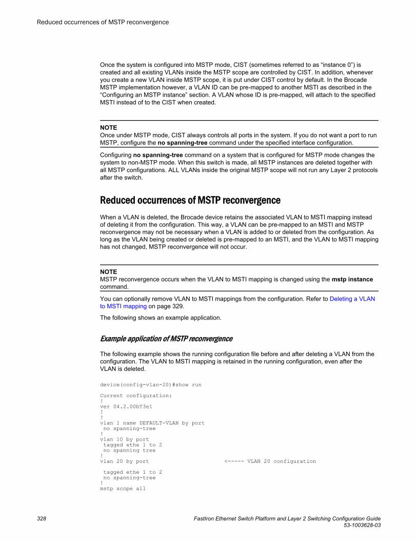
Once the system is configured into MSTP mode, CIST (sometimes referred to as “instance 0”) iscreated and all existing VLANs inside the MSTP scope are controlled by CIST. In addition, wheneveryou create a new VLAN inside MSTP scope, it is put under CIST control by default. In the BrocadeMSTP implementation however, a VLAN ID can be pre-mapped to another MSTI as described in the“Configuring an MSTP instance” section. A VLAN whose ID is pre-mapped, will attach to the specifiedMSTI instead of to the CIST when created.
NOTEOnce under MSTP mode, CIST always controls all ports in the system. If you do not want a port to runMSTP, configure the no spanning-tree command under the specified interface configuration.
Configuring no spanning-tree command on a system that is configured for MSTP mode changes thesystem to non-MSTP mode. When this switch is made, all MSTP instances are deleted together withall MSTP configurations. ALL VLANs inside the original MSTP scope will not run any Layer 2 protocolsafter the switch.
Reduced occurrences of MSTP reconvergenceWhen a VLAN is deleted, the Brocade device retains the associated VLAN to MSTI mapping insteadof deleting it from the configuration. This way, a VLAN can be pre-mapped to an MSTI and MSTPreconvergence may not be necessary when a VLAN is added to or deleted from the configuration. Aslong as the VLAN being created or deleted is pre-mapped to an MSTI, and the VLAN to MSTI mappinghas not changed, MSTP reconvergence will not occur.
NOTEMSTP reconvergence occurs when the VLAN to MSTI mapping is changed using the mstp instancecommand.
You can optionally remove VLAN to MSTI mappings from the configuration. Refer to Deleting a VLANto MSTI mapping on page 329.
The following shows an example application.
Example application of MSTP reconvergence
The following example shows the running configuration file before and after deleting a VLAN from theconfiguration. The VLAN to MSTI mapping is retained in the running configuration, even after theVLAN is deleted.
device(config-vlan-20)#show run Current configuration:!ver 04.2.00bT3e1!!vlan 1 name DEFAULT-VLAN by port no spanning-tree!vlan 10 by port tagged ethe 1 to 2 no spanning tree!vlan 20 by port <----- VLAN 20 configuration tagged ethe 1 to 2 no spanning-tree!mstp scope all
Reduced occurrences of MSTP reconvergence
328 FastIron Ethernet Switch Platform and Layer 2 Switching Configuration Guide53-1003628-03
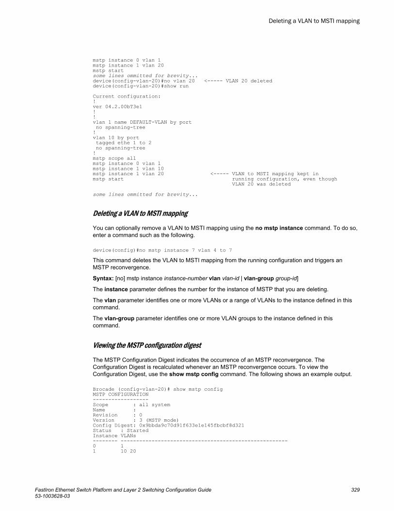
mstp instance 0 vlan 1mstp instance 1 vlan 20 mstp startsome lines ommitted for brevity... device(config-vlan-20)#no vlan 20 <----- VLAN 20 deleted device(config-vlan-20)#show run Current configuration:!ver 04.2.00bT3e1!!vlan 1 name DEFAULT-VLAN by port no spanning-tree!vlan 10 by port tagged ethe 1 to 2 no spanning-tree!mstp scope allmstp instance 0 vlan 1mstp instance 1 vlan 10mstp instance 1 vlan 20 <----- VLAN to MSTI mapping kept in mstp start running configuration, even though VLAN 20 was deleted some lines ommitted for brevity...
Deleting a VLAN to MSTI mapping
You can optionally remove a VLAN to MSTI mapping using the no mstp instance command. To do so,enter a command such as the following.
device(config)#no mstp instance 7 vlan 4 to 7 This command deletes the VLAN to MSTI mapping from the running configuration and triggers anMSTP reconvergence.
Syntax: [no] mstp instance instance-number vlan vlan-id | vlan-group group-id]
The instance parameter defines the number for the instance of MSTP that you are deleting.
The vlan parameter identifies one or more VLANs or a range of VLANs to the instance defined in thiscommand.
The vlan-group parameter identifies one or more VLAN groups to the instance defined in thiscommand.
Viewing the MSTP configuration digest
The MSTP Configuration Digest indicates the occurrence of an MSTP reconvergence. TheConfiguration Digest is recalculated whenever an MSTP reconvergence occurs. To view theConfiguration Digest, use the show mstp config command. The following shows an example output.
Brocade (config-vlan-20)# show mstp configMSTP CONFIGURATION------------------Scope : all systemName : Revision : 0Version : 3 (MSTP mode)Config Digest: 0x9bbda9c70d91f633e1e145fbcbf8d321 Status : StartedInstance VLANs-------- ------------------------------------------------------0 1 1 10 20
Deleting a VLAN to MSTI mapping
FastIron Ethernet Switch Platform and Layer 2 Switching Configuration Guide 32953-1003628-03
Syntax: show mstp config
Configuring additional MSTP parametersTo configure a switch for MSTP, you could configure the name and the revision on each switch that isbeing configured for MSTP. You must then create an MSTP Instance and assign an ID. VLANs arethen assigned to MSTP instances. These instances must be configured on all switches thatinteroperate with the same VLAN assignments. Port cost, priority and global parameters can then beconfigured for individual ports and instances. In addition, operational edge ports and point-to-pointlinks can be created and MSTP can be disabled on individual ports.
Each of the commands used to configure and operate MSTP are described in the following:
• Setting the MSTP name on page 330• Setting the MSTP revision number on page 330• Configuring an MSTP instance on page 331• Configuring bridge priority for an MSTP instance on page 331• Setting the MSTP global parameters on page 331• Setting ports to be operational edge ports on page 332• Setting automatic operational edge ports on page 332• Setting point-to-point link on page 332• Disabling MSTP on a port on page 334• Forcing ports to transmit an MSTP BPDU on page 334• Forcing ports to transmit an MSTP BPDU on page 334
Setting the MSTP name
Each switch that is running MSTP is configured with a name. It applies to the switch which can havemany different VLANs that can belong to many different MSTP regions.
To configure an MSTP name, use a command such as the following at the Global Configuration level.
device(config)#mstp name Brocade Syntax: [no] mstp name name
The name parameter defines an ASCII name for the MSTP configuration. The default name is for thename variable to be blank.
Setting the MSTP revision number
Each switch that is running MSTP is configured with a revision number. It applies to the switch whichcan have many different VLANs that can belong to many different MSTP regions.
To configure an MSTP revision number, use a command such as the following at the GlobalConfiguration level.
device(config)#mstp revision 4Syntax: [no] mstp revision revision-number
The revision parameter specifies the revision level for MSTP that you are configuring on the switch. Itcan be a number from 0 and 65535. The default revision number is 0.
Configuring additional MSTP parameters
330 FastIron Ethernet Switch Platform and Layer 2 Switching Configuration Guide53-1003628-03
Configuring an MSTP instance
An MSTP instance is configured with an MSTP ID for each region. Each region can contain one or moreVLANs. The Brocade implementation of MSTP allows you to assign VLANS or ranges of VLANs to anMSTP instance before or after they have been defined. If pre-defined, a VLAN will be placed in theMSTI that it was assigned to immediately when the VLAN is created. Otherwise, the default operation isto condition of assign all new VLANs to the CIST. VLANs assigned to the CIST by default can be movedlater to a specified MSTI.
To configure an MSTP instance and map one or more VLANs to that MSTI, use a command such asthe following at the Global Configuration level.
device(config)#mstp instance 7 vlan 4 to 7 Syntax: [no] mstp instance instance-number [ vlan vlan-id| vlan-group group-id]
The instance parameter defines the number for the instance of MSTP that you are configuring. Thevalue 0 (which identifies the CIST) cannot be used. You can have up to 15 instances, number 1 - 4094.
The vlan parameter assigns one or more VLANs or a range of VLANs to the instance defined in thiscommand.
The vlan-group parameter assigns one or more VLAN groups to the instance defined in this command.
The no option moves a VLAN or VLAN group from its assigned MSTI back into the CIST.
NOTEThe system does not allow an MSTI without any VLANs mapped to it. Consequently, removing allVLANs from an MSTI, deletes the MSTI from the system. The CIST by contrast will exist regardless ofwhether or not any VLANs are assigned to it or not. Consequently, if all VLANs are moved out of aCIST, the CIST will still exist and functional.
Configuring bridge priority for an MSTP instance
Priority can be configured for a specified instance. To configure priority for an MSTP instance, use acommand such as the following at the Global Configuration level.
device(config)#mstp instance 1 priority 8192 Syntax: [no] mstp instance instance-number priority priority-value
The instance-number variable is the number for the instance of MSTP that you are configuring.
You can set a priority to the instance that gives it forwarding preference over lower priority instanceswithin a VLAN or on the switch. A higher number for the priority variable means a lower forwardingpriority. Acceptable values are 0 - 61440 in increments of 4096. The default value is 32768.
Setting the MSTP global parameters
MSTP has many of the options available in RSTP as well as some unique options. To configure MSTPGlobal parameters for all instances on a switch.
device(config)#mstp force-version 0 forward-delay 10 hello-time 4 max-age 12 max-hops 9Syntax: [no] mstp force-version mode-number forward-delay value hello-time value max-age valuemax-hops value
Configuring an MSTP instance
FastIron Ethernet Switch Platform and Layer 2 Switching Configuration Guide 33153-1003628-03
The force-version parameter forces the bridge to send BPDUs in a specific format. You can specifyone of the following mode-number values:
• 0 - The STP compatibility mode. Only STP BPDUs will be sent. This is equivalent to single STP.• 2 - The RSTP compatibility mode. Only RSTP BPDUS will be sent. This is equivalent to single STP.• 3 - MSTP mode. In this default mode, only MSTP BPDUS will be sent.
The forward-delay value specifies how long a port waits before it forwards an RST BPDU after atopology change. This can be a value from 4 - 30 seconds. The default is 15 seconds.
The hello-time value parameter specifies the interval between two hello packets. The parameter canhave a value from 1 - 10 seconds. The default is 2 seconds.
The max-age value parameter specifies the amount of time the device waits to receive a hello packetbefore it initiates a topology change. You can specify a value from 6 - 40 seconds, where the valueadheres to the following formula.
max age equal to or greater than 2 x (hello-time + 1) AND max age equal to or greater than 2 x(forward-delay - 1)
The default max-age is 20 seconds.
The max-hops value parameter specifies the maximum hop count. You can specify a value from 1 -40 hops. The default value is 20 hops.
Setting ports to be operational edge ports
You can define specific ports as edge ports for the region in which they are configured to connect todevices (such as a host) that are not running STP, RSTP, or MSTP. If a port is connected to an enddevice such as a PC, the port can be configured as an edge port. To configure ports as operationaledge ports enter a command such as the following.
device(config)# mstp admin-edge-port ethernet 3/1/1Syntax: [no] mstp admin-edge-port ethernet port
Setting automatic operational edge ports
You can configure a Layer 3 switch to automatically set a port as an operational edge port if the portdoes not receive any BPDUs since link-up. If the port receives a BPDU later, it is automatically reset tobecome an operational non-edge port. This feature is set globally to apply to all ports on a routerwhere it is configured. This feature is configured as shown in the following.
device(config)#mstp edge-port-auto-detectSyntax: [no] mstp edge-port-auto-detect
NOTEIf this feature is enabled, it takes the port about 3 seconds longer to come to the enable state.
Setting point-to-point link
You can set a point-to-point link between ports to increase the speed of convergence. To create apoint-to-point link between ports, use a command such as the following at the Global Configurationlevel.
device(config)# mstp admin-pt2pt-mac ethernet 1/2/5 ethernet 1/4/5
Setting ports to be operational edge ports
332 FastIron Ethernet Switch Platform and Layer 2 Switching Configuration Guide53-1003628-03
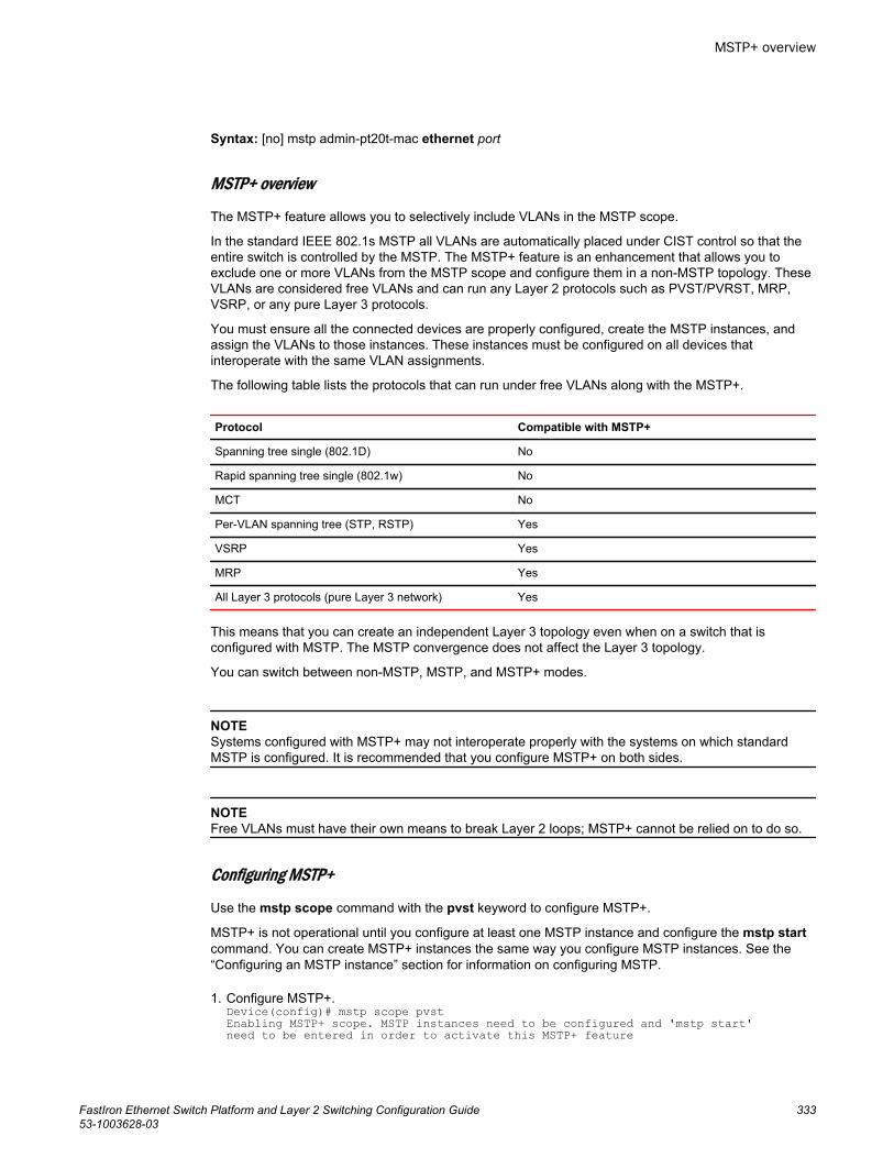
Syntax: [no] mstp admin-pt20t-mac ethernet port
MSTP+ overview
The MSTP+ feature allows you to selectively include VLANs in the MSTP scope.
In the standard IEEE 802.1s MSTP all VLANs are automatically placed under CIST control so that theentire switch is controlled by the MSTP. The MSTP+ feature is an enhancement that allows you toexclude one or more VLANs from the MSTP scope and configure them in a non-MSTP topology. TheseVLANs are considered free VLANs and can run any Layer 2 protocols such as PVST/PVRST, MRP,VSRP, or any pure Layer 3 protocols.
You must ensure all the connected devices are properly configured, create the MSTP instances, andassign the VLANs to those instances. These instances must be configured on all devices thatinteroperate with the same VLAN assignments.
The following table lists the protocols that can run under free VLANs along with the MSTP+.
Protocol Compatible with MSTP+
Spanning tree single (802.1D) No
Rapid spanning tree single (802.1w) No
MCT No
Per-VLAN spanning tree (STP, RSTP) Yes
VSRP Yes
MRP Yes
All Layer 3 protocols (pure Layer 3 network) Yes
This means that you can create an independent Layer 3 topology even when on a switch that isconfigured with MSTP. The MSTP convergence does not affect the Layer 3 topology.
You can switch between non-MSTP, MSTP, and MSTP+ modes.
NOTESystems configured with MSTP+ may not interoperate properly with the systems on which standardMSTP is configured. It is recommended that you configure MSTP+ on both sides.
NOTEFree VLANs must have their own means to break Layer 2 loops; MSTP+ cannot be relied on to do so.
Configuring MSTP+
Use the mstp scope command with the pvst keyword to configure MSTP+.
MSTP+ is not operational until you configure at least one MSTP instance and configure the mstp startcommand. You can create MSTP+ instances the same way you configure MSTP instances. See the“Configuring an MSTP instance” section for information on configuring MSTP.
1. Configure MSTP+.Device(config)# mstp scope pvstEnabling MSTP+ scope. MSTP instances need to be configured and 'mstp start' need to be entered in order to activate this MSTP+ feature
MSTP+ overview
FastIron Ethernet Switch Platform and Layer 2 Switching Configuration Guide 33353-1003628-03
Configures MSTP+. CIST is not automatically created and VLANs are not under MSTP scopeunless you explicitly configure the MSTP instances and attach the VLANs to them.
2. Create an MSTP instance.Device(config)# mstp instance 1 vlan 4 to 7Creates an MSTP instance on VLANs 4 to 7.
3. Start the MSTP+ protocol.Device(config)# mstp startCreates an MSTP instance on VLANs 4 to 7.
4. Remove the MSTP+ configuration.Device(config)# no mstp scope pvstRemoves the MSTP+ configuration. The VLANs that were attached to MSTP+ are out of MSTP+scope and there is no PVST under those VLANs. The non-MSTP VLANs are not affected.
Switching between non-MSTP, MSTP, and MSTP+ modes
Use the mstp scope command to switch between non-MSTP, MSTP, and MSTP+ modes. This allowsyou to move between modes without explicitly removing the current mode and reconfiguring the newmode.
When an MSTP instance is enabled, you can configure the pvst and all keywords to switch betweenmodes.
1. When the mstp scope all command is configured and MSTP mode is active, change to MSTP+mode.Device(config)# mstp scope pvstThe mode is changed to MSTP+. You can remove the VLANs from MSTP+ instances. VLANs thatare removed from MSTP+ scope become free and other supported protocols can be configured.
2. When the mstp scope pvst command is configured and MSTP+ mode is active, change to MSTPmode.Device(config)# mstp scope allThe mode is changed to MSTP. The VLANs that are already attached to MSTP+ are kept as is andall the free VLANs are attached to a CIST instance. Any protocols configured under the free VLANsare removed.
Disabling MSTP on a port
To disable MSTP on a specific port, use a command such as the following at the Global Configurationlevel.
device(config)#mstp disable ethernet 2/1/1Syntax: [no] mstp disable ethernet port
When a port is disabled for MSTP, it behaves as blocking for all the VLAN traffic that is controlled byMSTIs and the CIST.
Forcing ports to transmit an MSTP BPDU
To force a port to transmit an MSTP BPDU, use a command such as the following at the GlobalConfiguration level.
device(config)# mstp force-migration-check ethernet 3/1/1Syntax: [no] mstp force-migration-check ethernet port
Activating MSTP on a switch
Switching between non-MSTP, MSTP, and MSTP+ modes
334 FastIron Ethernet Switch Platform and Layer 2 Switching Configuration Guide53-1003628-03
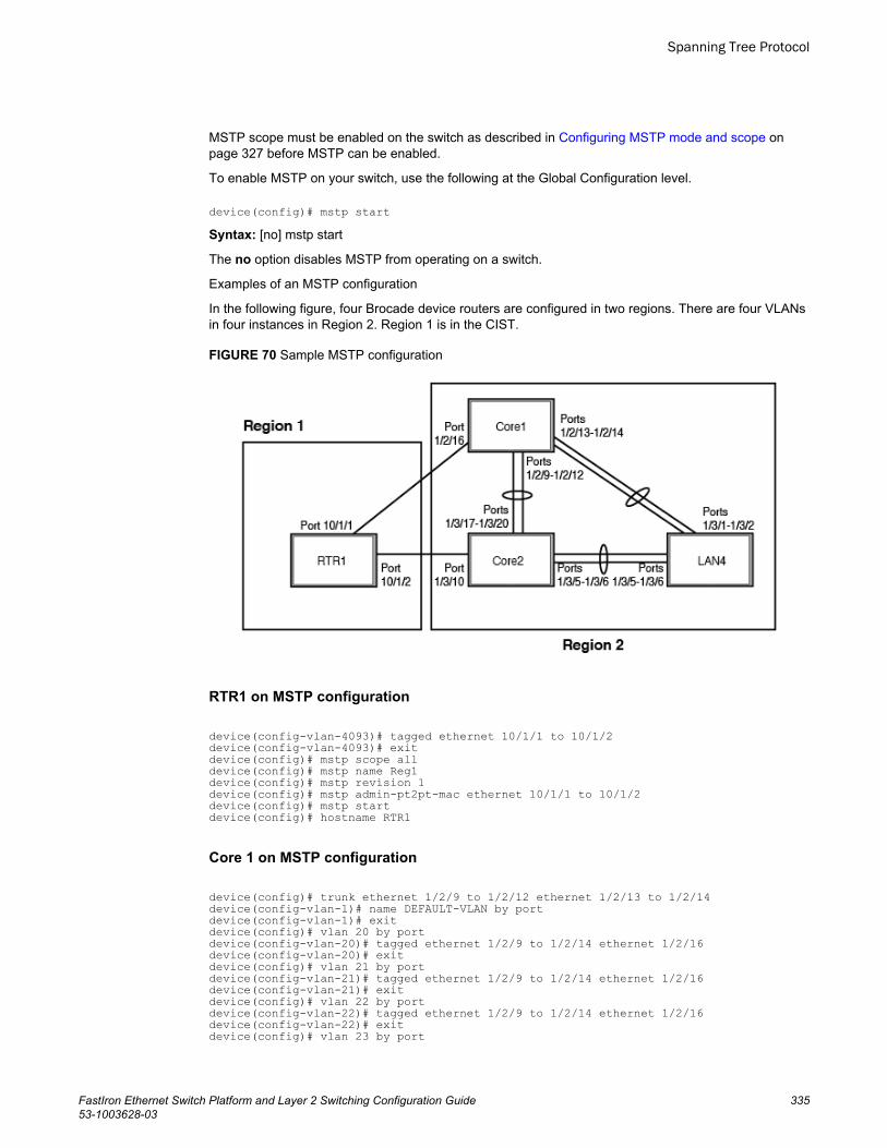
MSTP scope must be enabled on the switch as described in Configuring MSTP mode and scope onpage 327 before MSTP can be enabled.
To enable MSTP on your switch, use the following at the Global Configuration level.
device(config)# mstp startSyntax: [no] mstp start
The no option disables MSTP from operating on a switch.
Examples of an MSTP configuration
In the following figure, four Brocade device routers are configured in two regions. There are four VLANsin four instances in Region 2. Region 1 is in the CIST.
FIGURE 70 Sample MSTP configuration
RTR1 on MSTP configuration
device(config-vlan-4093)# tagged ethernet 10/1/1 to 10/1/2device(config-vlan-4093)# exitdevice(config)# mstp scope alldevice(config)# mstp name Reg1 device(config)# mstp revision 1device(config)# mstp admin-pt2pt-mac ethernet 10/1/1 to 10/1/2device(config)# mstp startdevice(config)# hostname RTR1
Core 1 on MSTP configuration
device(config)# trunk ethernet 1/2/9 to 1/2/12 ethernet 1/2/13 to 1/2/14device(config-vlan-1)# name DEFAULT-VLAN by portdevice(config-vlan-1)# exitdevice(config)# vlan 20 by portdevice(config-vlan-20)# tagged ethernet 1/2/9 to 1/2/14 ethernet 1/2/16device(config-vlan-20)# exitdevice(config)# vlan 21 by portdevice(config-vlan-21)# tagged ethernet 1/2/9 to 1/2/14 ethernet 1/2/16device(config-vlan-21)# exitdevice(config)# vlan 22 by portdevice(config-vlan-22)# tagged ethernet 1/2/9 to 1/2/14 ethernet 1/2/16device(config-vlan-22)# exitdevice(config)# vlan 23 by port
Spanning Tree Protocol
FastIron Ethernet Switch Platform and Layer 2 Switching Configuration Guide 33553-1003628-03
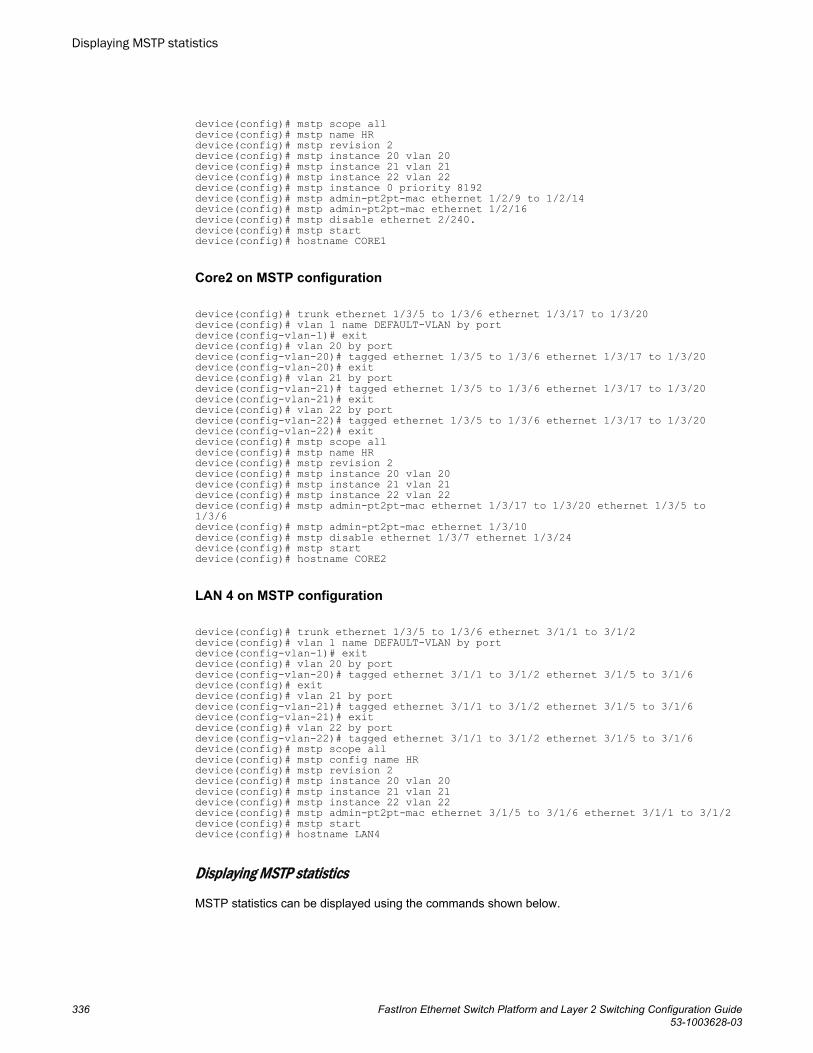
device(config)# mstp scope alldevice(config)# mstp name HR device(config)# mstp revision 2device(config)# mstp instance 20 vlan 20device(config)# mstp instance 21 vlan 21device(config)# mstp instance 22 vlan 22 device(config)# mstp instance 0 priority 8192device(config)# mstp admin-pt2pt-mac ethernet 1/2/9 to 1/2/14 device(config)# mstp admin-pt2pt-mac ethernet 1/2/16device(config)# mstp disable ethernet 2/240.device(config)# mstp startdevice(config)# hostname CORE1
Core2 on MSTP configuration
device(config)# trunk ethernet 1/3/5 to 1/3/6 ethernet 1/3/17 to 1/3/20device(config)# vlan 1 name DEFAULT-VLAN by portdevice(config-vlan-1)# exitdevice(config)# vlan 20 by portdevice(config-vlan-20)# tagged ethernet 1/3/5 to 1/3/6 ethernet 1/3/17 to 1/3/20device(config-vlan-20)# exitdevice(config)# vlan 21 by portdevice(config-vlan-21)# tagged ethernet 1/3/5 to 1/3/6 ethernet 1/3/17 to 1/3/20device(config-vlan-21)# exitdevice(config)# vlan 22 by portdevice(config-vlan-22)# tagged ethernet 1/3/5 to 1/3/6 ethernet 1/3/17 to 1/3/20device(config-vlan-22)# exitdevice(config)# mstp scope alldevice(config)# mstp name HR device(config)# mstp revision 2device(config)# mstp instance 20 vlan 20device(config)# mstp instance 21 vlan 21device(config)# mstp instance 22 vlan 22 device(config)# mstp admin-pt2pt-mac ethernet 1/3/17 to 1/3/20 ethernet 1/3/5 to 1/3/6device(config)# mstp admin-pt2pt-mac ethernet 1/3/10device(config)# mstp disable ethernet 1/3/7 ethernet 1/3/24device(config)# mstp startdevice(config)# hostname CORE2
LAN 4 on MSTP configuration
device(config)# trunk ethernet 1/3/5 to 1/3/6 ethernet 3/1/1 to 3/1/2device(config)# vlan 1 name DEFAULT-VLAN by portdevice(config-vlan-1)# exitdevice(config)# vlan 20 by portdevice(config-vlan-20)# tagged ethernet 3/1/1 to 3/1/2 ethernet 3/1/5 to 3/1/6device(config)# exitdevice(config)# vlan 21 by portdevice(config-vlan-21)# tagged ethernet 3/1/1 to 3/1/2 ethernet 3/1/5 to 3/1/6device(config-vlan-21)# exitdevice(config)# vlan 22 by portdevice(config-vlan-22)# tagged ethernet 3/1/1 to 3/1/2 ethernet 3/1/5 to 3/1/6device(config)# mstp scope alldevice(config)# mstp config name HR device(config)# mstp revision 2device(config)# mstp instance 20 vlan 20device(config)# mstp instance 21 vlan 21device(config)# mstp instance 22 vlan 22device(config)# mstp admin-pt2pt-mac ethernet 3/1/5 to 3/1/6 ethernet 3/1/1 to 3/1/2device(config)# mstp start device(config)# hostname LAN4
Displaying MSTP statistics
MSTP statistics can be displayed using the commands shown below.
Displaying MSTP statistics
336 FastIron Ethernet Switch Platform and Layer 2 Switching Configuration Guide53-1003628-03
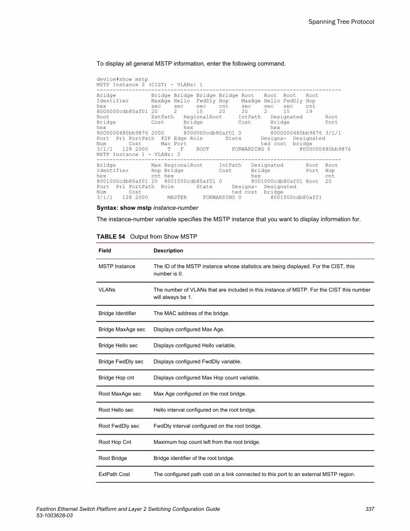
To display all general MSTP information, enter the following command.
device#show mstpMSTP Instance 0 (CIST) - VLANs: 1----------------------------------------------------------------------------Bridge Bridge Bridge Bridge Bridge Root Root Root RootIdentifier MaxAge Hello FwdDly Hop MaxAge Hello FwdDly Hophex sec sec sec cnt sec sec sec cnt8000000cdb80af01 20 2 15 20 20 2 15 19Root ExtPath RegionalRoot IntPath Designated RootBridge Cost Bridge Cost Bridge Porthex hex hex8000000480bb9876 2000 8000000cdb80af01 0 8000000480bb9876 3/1/1Port Pri PortPath P2P Edge Role State Designa- DesignatedNum Cost Mac Port ted cost bridge3/1/1 128 2000 T F ROOT FORWARDING 0 8000000480bb9876MSTP Instance 1 - VLANs: 2----------------------------------------------------------------------------Bridge Max RegionalRoot IntPath Designated Root RootIdentifier Hop Bridge Cost Bridge Port Hophex cnt hex hex cnt8001000cdb80af01 20 8001000cdb80af01 0 8001000cdb80af01 Root 20Port Pri PortPath Role State Designa- DesignatedNum Cost ted cost bridge3/1/1 128 2000 MASTER FORWARDING 0 8001000cdb80af01Syntax: show mstp instance-number
The instance-number variable specifies the MSTP instance that you want to display information for.
Output from Show MSTP TABLE 54
Field Description
MSTP Instance The ID of the MSTP instance whose statistics are being displayed. For the CIST, thisnumber is 0.
VLANs The number of VLANs that are included in this instance of MSTP. For the CIST this numberwill always be 1.
Bridge Identifier The MAC address of the bridge.
Bridge MaxAge sec Displays configured Max Age.
Bridge Hello sec Displays configured Hello variable.
Bridge FwdDly sec Displays configured FwdDly variable.
Bridge Hop cnt Displays configured Max Hop count variable.
Root MaxAge sec Max Age configured on the root bridge.
Root Hello sec Hello interval configured on the root bridge.
Root FwdDly sec FwdDly interval configured on the root bridge.
Root Hop Cnt Maximum hop count left from the root bridge.
Root Bridge Bridge identifier of the root bridge.
ExtPath Cost The configured path cost on a link connected to this port to an external MSTP region.
Spanning Tree Protocol
FastIron Ethernet Switch Platform and Layer 2 Switching Configuration Guide 33753-1003628-03
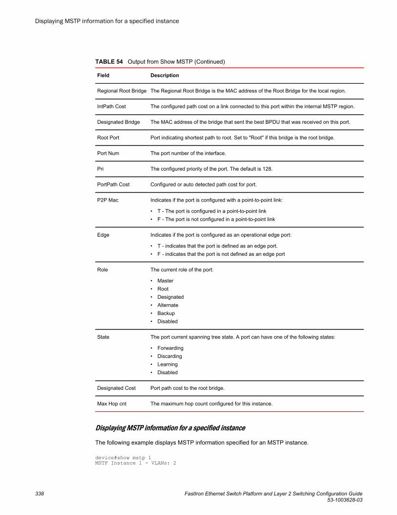
Output from Show MSTP (Continued)TABLE 54
Field Description
Regional Root Bridge The Regional Root Bridge is the MAC address of the Root Bridge for the local region.
IntPath Cost The configured path cost on a link connected to this port within the internal MSTP region.
Designated Bridge The MAC address of the bridge that sent the best BPDU that was received on this port.
Root Port Port indicating shortest path to root. Set to "Root" if this bridge is the root bridge.
Port Num The port number of the interface.
Pri The configured priority of the port. The default is 128.
PortPath Cost Configured or auto detected path cost for port.
P2P Mac Indicates if the port is configured with a point-to-point link:
• T - The port is configured in a point-to-point link• F - The port is not configured in a point-to-point link
Edge Indicates if the port is configured as an operational edge port:
• T - indicates that the port is defined as an edge port.• F - indicates that the port is not defined as an edge port
Role The current role of the port:
• Master• Root• Designated• Alternate• Backup• Disabled
State The port current spanning tree state. A port can have one of the following states:
• Forwarding• Discarding• Learning• Disabled
Designated Cost Port path cost to the root bridge.
Max Hop cnt The maximum hop count configured for this instance.
Displaying MSTP information for a specified instance
The following example displays MSTP information specified for an MSTP instance.
device#show mstp 1 MSTP Instance 1 - VLANs: 2
Displaying MSTP information for a specified instance
338 FastIron Ethernet Switch Platform and Layer 2 Switching Configuration Guide53-1003628-03
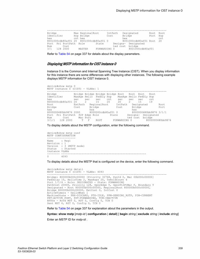
----------------------------------------------------------------------------Bridge Max RegionalRoot IntPath Designated Root RootIdentifier Hop Bridge Cost Bridge Port Hophex cnt hex hex cnt8001000cdb80af01 20 8001000cdb80af01 0 8001000cdb80af01 Root 20Port Pri PortPath Role State Designa- DesignatedNum Cost ted cost bridge3/1 128 2000 MASTER FORWARDING 0 8001000cdb80af01Refer to Table 54 on page 337 for details about the display parameters.
Displaying MSTP information for CIST instance 0
Instance 0 is the Common and Internal Spanning Tree Instance (CIST). When you display informationfor this instance there are some differences with displaying other instances. The following exampledisplays MSTP information for CIST Instance 0.
device#show mstp 0MSTP Instance 0 (CIST) - VLANs: 1----------------------------------------------------------------------------Bridge Bridge Bridge Bridge Bridge Root Root Root RootIdentifier MaxAge Hello FwdDly Hop MaxAge Hello FwdDly Hophex sec sec sec cnt sec sec sec cnt8000000cdb80af01 20 2 15 20 20 2 15 19Root ExtPath RegionalRoot IntPath Designated RootBridge Cost Bridge Cost Bridge Porthex hex hex8000000480bb9876 2000 8000000cdb80af01 0 8000000480bb9876 3/1/1Port Pri PortPath P2P Edge Role State Designa- DesignatedNum Cost Mac Port ted cost bridge3/1/1 128 2000 T F ROOT FORWARDING 0 8000000480bb9876To display details about the MSTP configuration, enter the following command.
device#show mstp confMSTP CONFIGURATION------------------Name : Reg1Revision : 1Version : 3 (MSTP mode)Status : StartedInstance VLANs-------- ------------------------------------------------------0 4093To display details about the MSTP that is configured on the device, enter the following command.
device#show mstp detailMSTP Instance 0 (CIST) - VLANs: 4093----------------------------------------------------------------------------Bridge: 800000b000c00000 [Priority 32768, SysId 0, Mac 00b000c00000]FwdDelay 15, HelloTime 2, MaxHops 20, TxHoldCount 6 Port 1/1/4 - Role: DESIGNATED - State: FORWARDINGPathCost 20000, Priority 128, OperEdge T, OperPt2PtMac F, Boundary TDesignated - Root 800000b000c00000, RegionalRoot 800000b000c00000,Bridge 800000b000c00000, ExtCost 0, IntCost 0ActiveTimers - helloWhen 1MachineState - PRX-DISCARD, PTX-IDLE, PPM-SENDING_RSTP, PIM-CURRENTPRT-ACTIVE_PORT, PST-FORWARDING, TCM-INACTIVEBPDUs - Rcvd MST 0, RST 0, Config 0, TCN 0Sent MST 6, RST 0, Config 0, TCN 0 Refer to Table 54 on page 337 for explanation about the parameters in the output.
Syntax: show mstp [mstp-id | configuration | detail] [ begin string | exclude string | include string]
Enter an MSTP ID for mstp-id .
Displaying MSTP information for CIST instance 0
FastIron Ethernet Switch Platform and Layer 2 Switching Configuration Guide 33953-1003628-03

Displaying MSTP information for CIST instance 0
340 FastIron Ethernet Switch Platform and Layer 2 Switching Configuration Guide53-1003628-03
VLANs
● VLAN overview..............................................................................................................341● Routing between VLANs............................................................................................... 366● Configuring IP subnet, IPX network and protocol-based VLANs.................................. 371● IP subnet, IPX network, and protocol-based VLANs within port-based VLANs............ 372● IPv6 protocol VLAN configuration................................................................................. 376● Routing between VLANs using virtual routing interfaces (Layer 3 Switches only)........376● Configuring protocol VLANs with dynamic ports........................................................... 381● Configuring uplink ports within a port-based VLAN.......................................................385● IP subnet address on multiple port-based VLANconfiguration......................................386● VLAN groups and virtual routing interface group ......................................................... 389● Super-aggregated VLAN configuration......................................................................... 394● 802.1ad tagging configuration.......................................................................................401● Private VLAN configuration........................................................................................... 405● Dual-mode VLAN ports................................................................................................. 415● Displaying VLAN information........................................................................................ 417
VLAN overviewThe following sections provide details about the VLAN types and features supported on the FastIronfamily of switches.
Types of VLANsThis section describes the VLAN types supported on Brocade devices.
VLAN support on FastIron devices
You can configure the following types of VLANs on FastIron devices:
• Layer 2 port-based VLAN - a set of physical ports that share a common, exclusive Layer 2 broadcastdomain
• Layer 3 protocol VLANs - a subset of ports within a port-based VLAN that share a common, exclusivebroadcast domain for Layer 3 broadcasts of the specified protocol type
• IP subnet VLANs - a subset of ports in a port-based VLAN that share a common, exclusive subnetbroadcast domain for a specified IP subnet
• IPv6 VLANs - a subset of ports in a port-based VLAN that share a common, exclusive networkbroadcast domain for IPv6 packets
• IPX network VLANs - a subset of ports in a port-based VLAN that share a common, exclusivenetwork broadcast domain for a specified IPX network
• AppleTalk cable VLANs - a subset of ports in a port-based-based VLAN that share a common,exclusive network broadcast domain for a specified AppleTalk cable range
FastIron Ethernet Switch Platform and Layer 2 Switching Configuration Guide 34153-1003628-03
NOTEIPX and AppleTalk VLANs are not present in the ICX 7xxx series devices.
When a FastIron device receives a packet on a port that is a member of a VLAN, the device forwardsthe packet based on the following VLAN hierarchy:
• If the port belongs to an IP subnet VLAN, IPX network VLAN, or AppleTalk cable VLAN and thepacket belongs to the corresponding IP subnet, IPX network, or AppleTalk cable range, the deviceforwards the packet to all the ports within that VLAN.
• If the packet is a Layer 3 packet but cannot be forwarded as described above, but the port is amember of a Layer 3 protocol VLAN for the packet protocol, the device forwards the packet on allthe Layer 3 protocol VLAN ports.
• If the packet cannot be forwarded based on either of the VLAN membership types listed above, butthe packet can be forwarded at Layer 2, the device forwards the packet on all the ports within thereceiving port port-based VLAN.
Protocol VLANs differ from IP subnet, IPX network, and AppleTalk VLANs in an important way.Protocol VLANs accept any broadcast of the specified protocol type. An IP subnet, IPX network, orAppleTalk VLAN accepts only broadcasts for the specified IP subnet, IPX network, or AppleTalk cablerange.
NOTEProtocol VLANs are different from IP subnet, IPX network, and AppleTalk cable VLANs. A port-basedVLAN cannot contain both an IP subnet, IPX network, or AppleTalk cable VLAN and a protocol VLANfor the same protocol. For example, a port-based VLAN cannot contain both an IP protocol VLAN andan IP subnet VLAN.
Layer 2 port-based VLANs
On all Brocade devices, you can configure port-based VLANs. A port-based VLAN is a subset of portson a Brocade device that constitutes a Layer 2 broadcast domain.
By default, all the ports on a Brocade device are members of the default VLAN. Thus, all the ports onthe device constitute a single Layer 2 broadcast domain. When you configure a port-based VLAN, thedevice automatically removes the ports you add to the VLAN from the default VLAN.
You can configure multiple port-based VLANs. You can configure up to 4094 port-based VLANs on aLayer 2 Switch or Layer 3 Switch. On both device types, valid VLAN IDs are 1 - 4095. You canconfigure up to the maximum number of VLANs within that ID range.
NOTEVLAN IDs 4087, 4090, and 4093 are reserved for Brocade internal use only. VLAN 4094 is reservedfor use by Single STP. If you want to use VLANs 4091 and 4092 as configurable VLANs, you canassign them to different VLAN IDs. For more information, refer to Assigning different VLAN IDs toreserved VLANs 4091 and 4092 on page 368
NOTEEach port-based VLAN can contain either tagged or untagged ports. A port cannot be a member ofmore than one port-based VLAN unless the port is tagged. 802.1Q tagging allows the port to add afour-byte tag field, which contains the VLAN ID, to each packet sent on the port. You also canconfigure port-based VLANs that span multiple devices by tagging the ports within the VLAN. The tag
Layer 2 port-based VLANs
342 FastIron Ethernet Switch Platform and Layer 2 Switching Configuration Guide53-1003628-03
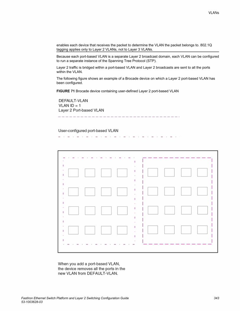
enables each device that receives the packet to determine the VLAN the packet belongs to. 802.1Qtagging applies only to Layer 2 VLANs, not to Layer 3 VLANs.
Because each port-based VLAN is a separate Layer 2 broadcast domain, each VLAN can be configuredto run a separate instance of the Spanning Tree Protocol (STP).
Layer 2 traffic is bridged within a port-based VLAN and Layer 2 broadcasts are sent to all the portswithin the VLAN.
The following figure shows an example of a Brocade device on which a Layer 2 port-based VLAN hasbeen configured.
FIGURE 71 Brocade device containing user-defined Layer 2 port-based VLAN
VLANs
FastIron Ethernet Switch Platform and Layer 2 Switching Configuration Guide 34353-1003628-03
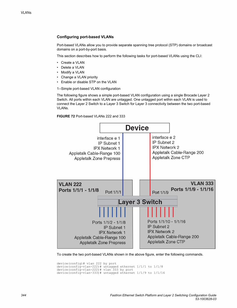
Configuring port-based VLANs
Port-based VLANs allow you to provide separate spanning tree protocol (STP) domains or broadcastdomains on a port-by-port basis.
This section describes how to perform the following tasks for port-based VLANs using the CLI:
• Create a VLAN• Delete a VLAN• Modify a VLAN• Change a VLAN priority• Enable or disable STP on the VLAN
1--Simple port-based VLAN configuration
The following figure shows a simple port-based VLAN configuration using a single Brocade Layer 2Switch. All ports within each VLAN are untagged. One untagged port within each VLAN is used toconnect the Layer 2 Switch to a Layer 3 Switch for Layer 3 connectivity between the two port-basedVLANs.
FIGURE 72 Port-based VLANs 222 and 333
To create the two port-based VLANs shown in the above figure, enter the following commands.
device(config)# vlan 222 by portdevice(config-vlan-222)# untagged ethernet 1/1/1 to 1/1/8device(config-vlan-222)# vlan 333 by portdevice(config-vlan-333)# untagged ethernet 1/1/9 to 1/1/16
VLANs
344 FastIron Ethernet Switch Platform and Layer 2 Switching Configuration Guide53-1003628-03
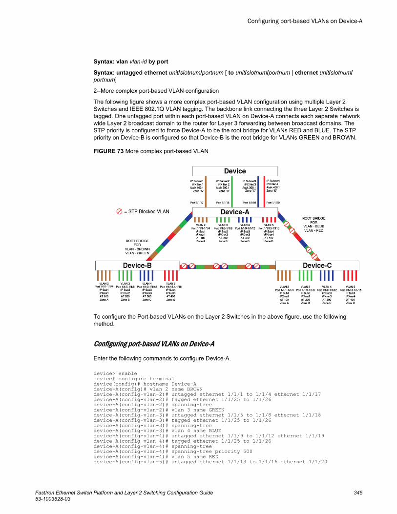
Syntax: vlan vlan-id by port
Syntax: untagged ethernet unit/slotnum/portnum [ to unit/slotnum/portnum | ethernet unit/slotnum/portnum]
2--More complex port-based VLAN configuration
The following figure shows a more complex port-based VLAN configuration using multiple Layer 2Switches and IEEE 802.1Q VLAN tagging. The backbone link connecting the three Layer 2 Switches istagged. One untagged port within each port-based VLAN on Device-A connects each separate networkwide Layer 2 broadcast domain to the router for Layer 3 forwarding between broadcast domains. TheSTP priority is configured to force Device-A to be the root bridge for VLANs RED and BLUE. The STPpriority on Device-B is configured so that Device-B is the root bridge for VLANs GREEN and BROWN.
FIGURE 73 More complex port-based VLAN
To configure the Port-based VLANs on the Layer 2 Switches in the above figure, use the followingmethod.
Configuring port-based VLANs on Device-A
Enter the following commands to configure Device-A.
device> enabledevice# configure terminaldevice(config)# hostname Device-Adevice-A(config)# vlan 2 name BROWNdevice-A(config-vlan-2)# untagged ethernet 1/1/1 to 1/1/4 ethernet 1/1/17device-A(config-vlan-2)# tagged ethernet 1/1/25 to 1/1/26device-A(config-vlan-2)# spanning-treedevice-A(config-vlan-2)# vlan 3 name GREENdevice-A(config-vlan-3)# untagged ethernet 1/1/5 to 1/1/8 ethernet 1/1/18device-A(config-vlan-3)# tagged ethernet 1/1/25 to 1/1/26device-A(config-vlan-3)# spanning-treedevice-A(config-vlan-3)# vlan 4 name BLUEdevice-A(config-vlan-4)# untagged ethernet 1/1/9 to 1/1/12 ethernet 1/1/19device-A(config-vlan-4)# tagged ethernet 1/1/25 to 1/1/26device-A(config-vlan-4)# spanning-treedevice-A(config-vlan-4)# spanning-tree priority 500device-A(config-vlan-4)# vlan 5 name REDdevice-A(config-vlan-5)# untagged ethernet 1/1/13 to 1/1/16 ethernet 1/1/20
Configuring port-based VLANs on Device-A
FastIron Ethernet Switch Platform and Layer 2 Switching Configuration Guide 34553-1003628-03
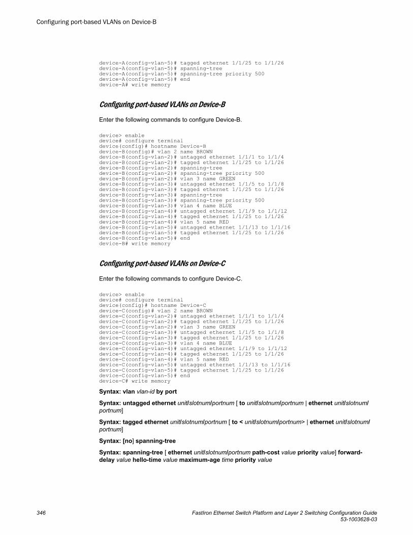
device-A(config-vlan-5)# tagged ethernet 1/1/25 to 1/1/26device-A(config-vlan-5)# spanning-treedevice-A(config-vlan-5)# spanning-tree priority 500device-A(config-vlan-5)# enddevice-A# write memory
Configuring port-based VLANs on Device-B
Enter the following commands to configure Device-B.
device> enabledevice# configure terminaldevice(config)# hostname Device-Bdevice-B(config)# vlan 2 name BROWNdevice-B(config-vlan-2)# untagged ethernet 1/1/1 to 1/1/4device-B(config-vlan-2)# tagged ethernet 1/1/25 to 1/1/26device-B(config-vlan-2)# spanning-treedevice-B(config-vlan-2)# spanning-tree priority 500device-B(config-vlan-2)# vlan 3 name GREENdevice-B(config-vlan-3)# untagged ethernet 1/1/5 to 1/1/8device-B(config-vlan-3)# tagged ethernet 1/1/25 to 1/1/26device-B(config-vlan-3)# spanning-treedevice-B(config-vlan-3)# spanning-tree priority 500device-B(config-vlan-3)# vlan 4 name BLUEdevice-B(config-vlan-4)# untagged ethernet 1/1/9 to 1/1/12device-B(config-vlan-4)# tagged ethernet 1/1/25 to 1/1/26device-B(config-vlan-4)# vlan 5 name REDdevice-B(config-vlan-5)# untagged ethernet 1/1/13 to 1/1/16device-B(config-vlan-5)# tagged ethernet 1/1/25 to 1/1/26device-B(config-vlan-5)# enddevice-B# write memory
Configuring port-based VLANs on Device-C
Enter the following commands to configure Device-C.
device> enabledevice# configure terminaldevice(config)# hostname Device-Cdevice-C(config)# vlan 2 name BROWNdevice-C(config-vlan-2)# untagged ethernet 1/1/1 to 1/1/4device-C(config-vlan-2)# tagged ethernet 1/1/25 to 1/1/26device-C(config-vlan-2)# vlan 3 name GREENdevice-C(config-vlan-3)# untagged ethernet 1/1/5 to 1/1/8device-C(config-vlan-3)# tagged ethernet 1/1/25 to 1/1/26device-C(config-vlan-3)# vlan 4 name BLUEdevice-C(config-vlan-4)# untagged ethernet 1/1/9 to 1/1/12device-C(config-vlan-4)# tagged ethernet 1/1/25 to 1/1/26device-C(config-vlan-4)# vlan 5 name REDdevice-C(config-vlan-5)# untagged ethernet 1/1/13 to 1/1/16device-C(config-vlan-5)# tagged ethernet 1/1/25 to 1/1/26device-C(config-vlan-5)# enddevice-C# write memorySyntax: vlan vlan-id by port
Syntax: untagged ethernet unit/slotnum/portnum [ to unit/slotnum/portnum | ethernet unit/slotnum/portnum]
Syntax: tagged ethernet unit/slotnum/portnum [ to < unit/slotnum/portnum> | ethernet unit/slotnum/portnum]
Syntax: [no] spanning-tree
Syntax: spanning-tree [ ethernet unit/slotnum/portnum path-cost value priority value] forward-delay value hello-time value maximum-age time priority value
Configuring port-based VLANs on Device-B
346 FastIron Ethernet Switch Platform and Layer 2 Switching Configuration Guide53-1003628-03
Modifying a port-based VLANYou can make the following modifications to a port-based VLAN:
• Add or delete a VLAN port.• Enable or disable STP.
Removing a port-based VLAN
Suppose you want to remove VLAN 5 from the example in Figure 73 on page 345. To do so, use thefollowing procedure.
1. Access the global CONFIG level of the CLI on Device-A by entering the following commands.
device-A> enableNo password has been assigned yet...
device-A# configure terminaldevice-A(config)#
2. Enter the following command.
device-A(config)# no vlan 5device-A(config)#
3. Enter the following commands to exit the CONFIG level and save the configuration to the system-config file on flash memory.
device-A(config)# device-A(config)# enddevice-A# write memorydevice-A#
4. Repeat steps 1 - 3 on Device-B.
Syntax: [no] vlan vlan-id by port
Removing a port from a VLAN
Suppose you want to remove port 11 from VLAN 4 on Device-A shown in Figure 73 on page 345. To doso, use the following procedure.
1. Access the global CONFIG level of the CLI on Device-A by entering the following command.
device-A> enableNo password has been assigned yet...
device-A# configure terminaldevice-A(config)#
2. Access the level of the CLI for configuring port-based VLAN 4 by entering the following command.
device-A(config)# device-A(config)# vlan 4device-A(config-vlan-4)#
3. Enter the following commands.
device-A(config-vlan-4)# device-A(config-vlan-4)# no untagged ethernet 11deleted port ethe 11 from port-vlan 4.device-A(config-vlan-4)#
4. Enter the following commands to exit the VLAN CONFIG mode and save the configuration to thesystem-config file on flash memory.
device-A(config-vlan-4)# device-A(config-vlan-4)# enddevice-A# write memory
Modifying a port-based VLAN
FastIron Ethernet Switch Platform and Layer 2 Switching Configuration Guide 34753-1003628-03
You can remove all the ports from a port-based VLAN without losing the rest of the VLANconfiguration. However, you cannot configure an IP address on a virtual routing interface unless theVLAN contains ports. If the VLAN has a virtual routing interface, the virtual routing interface IPaddress is deleted when the ports associated with the interface are deleted. The rest of the VLANconfiguration is retained.
Multi-range VLAN
The multi-range VLAN feature allows users to use a single command to create and configure multipleVLANs. These VLANs can be continuous, for example from 2 to 7 or discontinuous, for example, 2 47.
NOTEThe maximum number of VLANs you can create or configure with a single command is 64.
Creating a multi-range VLAN
To create more than one VLAN with a single command, you can specify the VLAN number and range.
Syntax: [no] vlan num to num
The num parameter specifies the VLAN ID.
To create a continuous range of VLANs, enter command such as the following.
device(config)#vlan 2 to 7device(config-mvlan-2-7)#Syntax: [no] vlan num to num
To create discontinuous VLANs, enter command such as the following.
device(config)#vlan 2 4 7device(config-mvlan-2*7)#exitSyntax: [no] vlan num num num
You can also create continuous and discontinuous VLANs. To create continuous and discontinuousVLANs, enter command such as the following.
device(config)#vlan 2 to 7 20 25device(config-mvlan-2*25)#Syntax: [no] vlan num to num num
Deleting a multi-range VLAN
You can also delete multiple VLANs with a single command.
To delete a continuous range of VLANs, enter command such as the following.
device(config)#no vlan 2 to 7Syntax: [no] vlan num to num
To delete discontinuous VLANs, enter command such as the following.
device(config)#no vlan 2 4 7Syntax: [no] vlan num num num
Multi-range VLAN
348 FastIron Ethernet Switch Platform and Layer 2 Switching Configuration Guide53-1003628-03
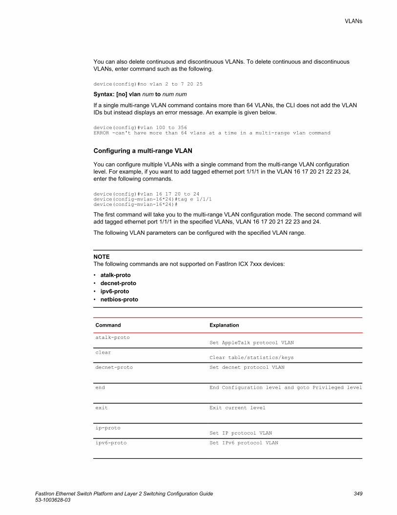
You can also delete continuous and discontinuous VLANs. To delete continuous and discontinuousVLANs, enter command such as the following.
device(config)#no vlan 2 to 7 20 25Syntax: [no] vlan num to num num
If a single multi-range VLAN command contains more than 64 VLANs, the CLI does not add the VLANIDs but instead displays an error message. An example is given below.
device(config)#vlan 100 to 356ERROR -can't have more than 64 vlans at a time in a multi-range vlan command
Configuring a multi-range VLAN
You can configure multiple VLANs with a single command from the multi-range VLAN configurationlevel. For example, if you want to add tagged ethernet port 1/1/1 in the VLAN 16 17 20 21 22 23 24,enter the following commands.
device(config)#vlan 16 17 20 to 24device(config-mvlan-16*24)#tag e 1/1/1device(config-mvlan-16*24)#The first command will take you to the multi-range VLAN configuration mode. The second command willadd tagged ethernet port 1/1/1 in the specified VLANs, VLAN 16 17 20 21 22 23 and 24.
The following VLAN parameters can be configured with the specified VLAN range.
NOTEThe following commands are not supported on FastIron ICX 7xxx devices:
• atalk-proto• decnet-proto• ipv6-proto• netbios-proto
Command Explanation
atalk-protoSet AppleTalk protocol VLAN
clearClear table/statistics/keys
decnet-proto Set decnet protocol VLAN
end End Configuration level and goto Privileged level
exit Exit current level
ip-protoSet IP protocol VLAN
ipv6-proto Set IPv6 protocol VLAN
VLANs
FastIron Ethernet Switch Platform and Layer 2 Switching Configuration Guide 34953-1003628-03
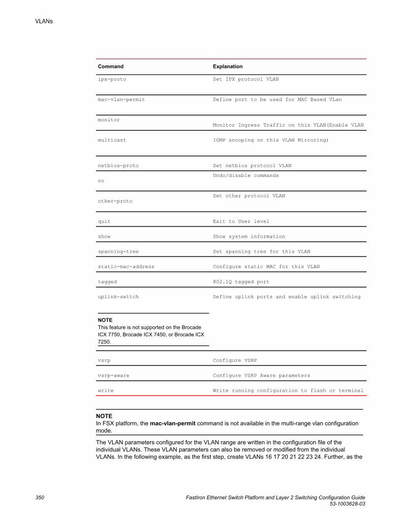
Command Explanation
ipx-proto Set IPX protocol VLAN
mac-vlan-permit Define port to be used for MAC Based VLan
monitorMonitor Ingress Traffic on this VLAN(Enable VLAN
multicast IGMP snooping on this VLAN Mirroring)
netbios-proto Set netbios protocol VLAN
noUndo/disable commands
other-protoSet other protocol VLAN
quit Exit to User level
show Show system information
spanning-tree Set spanning tree for this VLAN
static-mac-address Configure static MAC for this VLAN
tagged 802.1Q tagged port
uplink-switch
NOTEThis feature is not supported on the BrocadeICX 7750, Brocade ICX 7450, or Brocade ICX7250.
Define uplink ports and enable uplink switching
vsrp Configure VSRP
vsrp-aware Configure VSRP Aware parameters
write Write running configuration to flash or terminal
NOTEIn FSX platform, the mac-vlan-permit command is not available in the multi-range vlan configurationmode.
The VLAN parameters configured for the VLAN range are written in the configuration file of theindividual VLANs. These VLAN parameters can also be removed or modified from the individualVLANs. In the following example, as the first step, create VLANs 16 17 20 21 22 23 24. Further, as the
VLANs
350 FastIron Ethernet Switch Platform and Layer 2 Switching Configuration Guide53-1003628-03
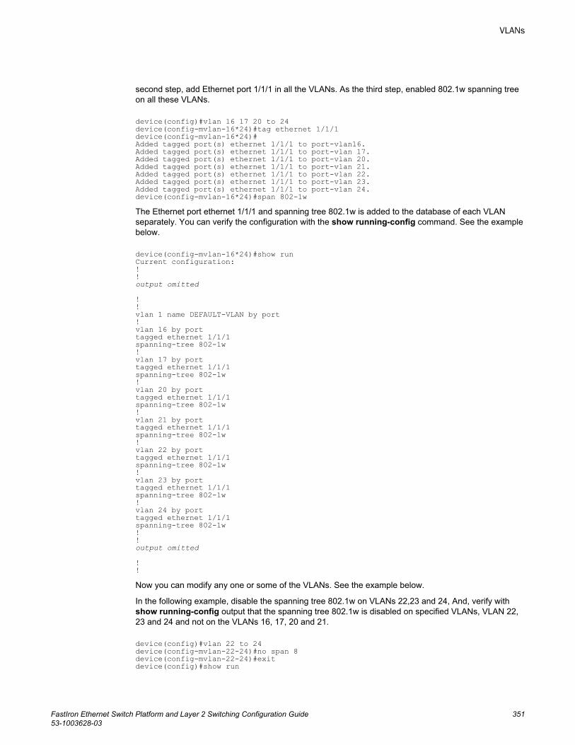
second step, add Ethernet port 1/1/1 in all the VLANs. As the third step, enabled 802.1w spanning treeon all these VLANs.
device(config)#vlan 16 17 20 to 24device(config-mvlan-16*24)#tag ethernet 1/1/1device(config-mvlan-16*24)#Added tagged port(s) ethernet 1/1/1 to port-vlan16.Added tagged port(s) ethernet 1/1/1 to port-vlan 17.Added tagged port(s) ethernet 1/1/1 to port-vlan 20.Added tagged port(s) ethernet 1/1/1 to port-vlan 21.Added tagged port(s) ethernet 1/1/1 to port-vlan 22.Added tagged port(s) ethernet 1/1/1 to port-vlan 23.Added tagged port(s) ethernet 1/1/1 to port-vlan 24.device(config-mvlan-16*24)#span 802-1wThe Ethernet port ethernet 1/1/1 and spanning tree 802.1w is added to the database of each VLANseparately. You can verify the configuration with the show running-config command. See the examplebelow.
device(config-mvlan-16*24)#show runCurrent configuration:!!output omitted
!!vlan 1 name DEFAULT-VLAN by port!vlan 16 by porttagged ethernet 1/1/1spanning-tree 802-1w!vlan 17 by porttagged ethernet 1/1/1spanning-tree 802-1w!vlan 20 by porttagged ethernet 1/1/1spanning-tree 802-1w!vlan 21 by porttagged ethernet 1/1/1spanning-tree 802-1w!vlan 22 by porttagged ethernet 1/1/1spanning-tree 802-1w!vlan 23 by porttagged ethernet 1/1/1spanning-tree 802-1w!vlan 24 by porttagged ethernet 1/1/1spanning-tree 802-1w!!output omitted
!!Now you can modify any one or some of the VLANs. See the example below.
In the following example, disable the spanning tree 802.1w on VLANs 22,23 and 24, And, verify withshow running-config output that the spanning tree 802.1w is disabled on specified VLANs, VLAN 22,23 and 24 and not on the VLANs 16, 17, 20 and 21.
device(config)#vlan 22 to 24device(config-mvlan-22-24)#no span 8device(config-mvlan-22-24)#exitdevice(config)#show run
VLANs
FastIron Ethernet Switch Platform and Layer 2 Switching Configuration Guide 35153-1003628-03
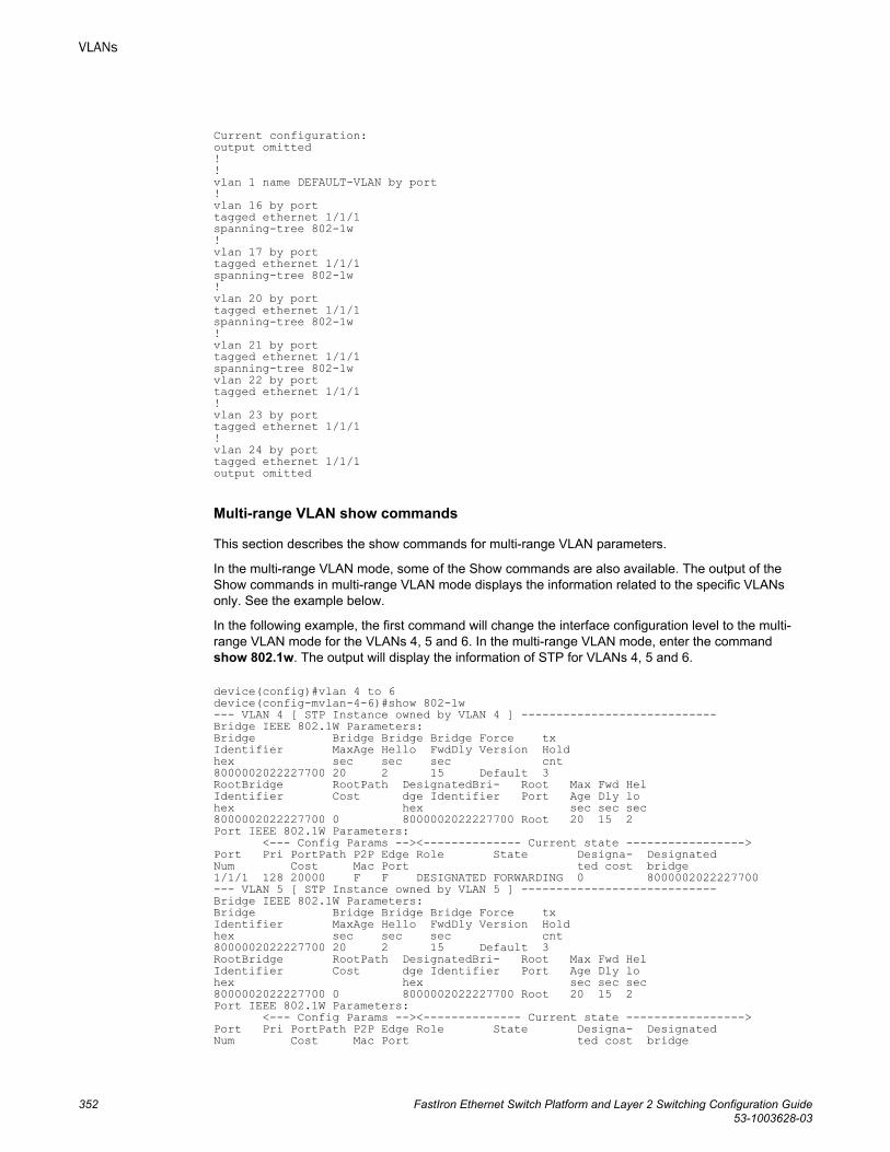
Current configuration:output omitted!!vlan 1 name DEFAULT-VLAN by port!vlan 16 by porttagged ethernet 1/1/1spanning-tree 802-1w!vlan 17 by porttagged ethernet 1/1/1spanning-tree 802-1w!vlan 20 by porttagged ethernet 1/1/1spanning-tree 802-1w!vlan 21 by porttagged ethernet 1/1/1spanning-tree 802-1wvlan 22 by porttagged ethernet 1/1/1!vlan 23 by porttagged ethernet 1/1/1!vlan 24 by porttagged ethernet 1/1/1output omitted
Multi-range VLAN show commands
This section describes the show commands for multi-range VLAN parameters.
In the multi-range VLAN mode, some of the Show commands are also available. The output of theShow commands in multi-range VLAN mode displays the information related to the specific VLANsonly. See the example below.
In the following example, the first command will change the interface configuration level to the multi-range VLAN mode for the VLANs 4, 5 and 6. In the multi-range VLAN mode, enter the commandshow 802.1w. The output will display the information of STP for VLANs 4, 5 and 6.
device(config)#vlan 4 to 6device(config-mvlan-4-6)#show 802-1w--- VLAN 4 [ STP Instance owned by VLAN 4 ] ----------------------------Bridge IEEE 802.1W Parameters:Bridge Bridge Bridge Bridge Force txIdentifier MaxAge Hello FwdDly Version Holdhex sec sec sec cnt8000002022227700 20 2 15 Default 3RootBridge RootPath DesignatedBri- Root Max Fwd HelIdentifier Cost dge Identifier Port Age Dly lohex hex sec sec sec8000002022227700 0 8000002022227700 Root 20 15 2Port IEEE 802.1W Parameters: <--- Config Params --><-------------- Current state ----------------->Port Pri PortPath P2P Edge Role State Designa- DesignatedNum Cost Mac Port ted cost bridge1/1/1 128 20000 F F DESIGNATED FORWARDING 0 8000002022227700--- VLAN 5 [ STP Instance owned by VLAN 5 ] ----------------------------Bridge IEEE 802.1W Parameters:Bridge Bridge Bridge Bridge Force txIdentifier MaxAge Hello FwdDly Version Holdhex sec sec sec cnt8000002022227700 20 2 15 Default 3RootBridge RootPath DesignatedBri- Root Max Fwd HelIdentifier Cost dge Identifier Port Age Dly lohex hex sec sec sec8000002022227700 0 8000002022227700 Root 20 15 2Port IEEE 802.1W Parameters: <--- Config Params --><-------------- Current state ----------------->Port Pri PortPath P2P Edge Role State Designa- DesignatedNum Cost Mac Port ted cost bridge
VLANs
352 FastIron Ethernet Switch Platform and Layer 2 Switching Configuration Guide53-1003628-03
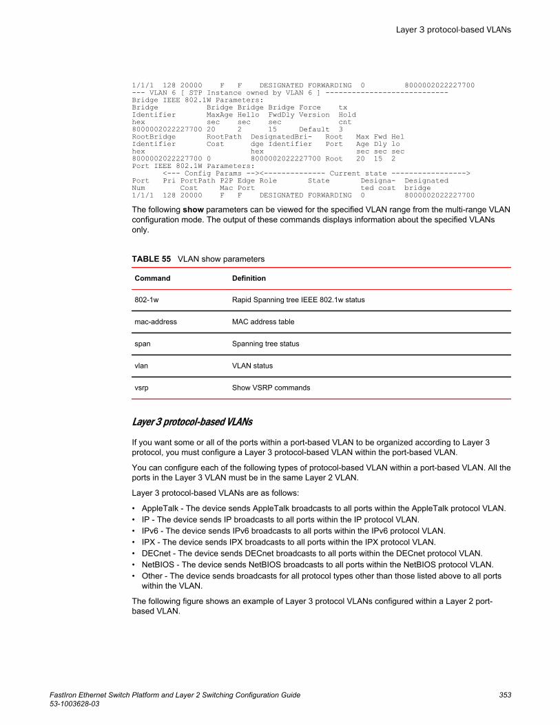
1/1/1 128 20000 F F DESIGNATED FORWARDING 0 8000002022227700--- VLAN 6 [ STP Instance owned by VLAN 6 ] ----------------------------Bridge IEEE 802.1W Parameters:Bridge Bridge Bridge Bridge Force txIdentifier MaxAge Hello FwdDly Version Holdhex sec sec sec cnt8000002022227700 20 2 15 Default 3RootBridge RootPath DesignatedBri- Root Max Fwd HelIdentifier Cost dge Identifier Port Age Dly lohex hex sec sec sec8000002022227700 0 8000002022227700 Root 20 15 2Port IEEE 802.1W Parameters: <--- Config Params --><-------------- Current state ----------------->Port Pri PortPath P2P Edge Role State Designa- DesignatedNum Cost Mac Port ted cost bridge1/1/1 128 20000 F F DESIGNATED FORWARDING 0 8000002022227700The following show parameters can be viewed for the specified VLAN range from the multi-range VLANconfiguration mode. The output of these commands displays information about the specified VLANsonly.
VLAN show parametersTABLE 55
Command Definition
802-1w Rapid Spanning tree IEEE 802.1w status
mac-address MAC address table
span Spanning tree status
vlan VLAN status
vsrp Show VSRP commands
Layer 3 protocol-based VLANs
If you want some or all of the ports within a port-based VLAN to be organized according to Layer 3protocol, you must configure a Layer 3 protocol-based VLAN within the port-based VLAN.
You can configure each of the following types of protocol-based VLAN within a port-based VLAN. All theports in the Layer 3 VLAN must be in the same Layer 2 VLAN.
Layer 3 protocol-based VLANs are as follows:
• AppleTalk - The device sends AppleTalk broadcasts to all ports within the AppleTalk protocol VLAN.• IP - The device sends IP broadcasts to all ports within the IP protocol VLAN.• IPv6 - The device sends IPv6 broadcasts to all ports within the IPv6 protocol VLAN.• IPX - The device sends IPX broadcasts to all ports within the IPX protocol VLAN.• DECnet - The device sends DECnet broadcasts to all ports within the DECnet protocol VLAN.• NetBIOS - The device sends NetBIOS broadcasts to all ports within the NetBIOS protocol VLAN.• Other - The device sends broadcasts for all protocol types other than those listed above to all ports
within the VLAN.
The following figure shows an example of Layer 3 protocol VLANs configured within a Layer 2 port-based VLAN.
Layer 3 protocol-based VLANs
FastIron Ethernet Switch Platform and Layer 2 Switching Configuration Guide 35353-1003628-03
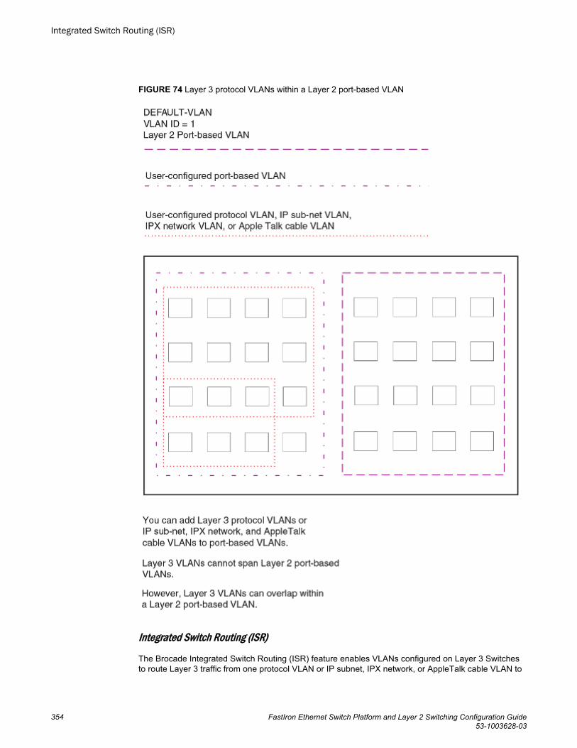
FIGURE 74 Layer 3 protocol VLANs within a Layer 2 port-based VLAN
Integrated Switch Routing (ISR)
The Brocade Integrated Switch Routing (ISR) feature enables VLANs configured on Layer 3 Switchesto route Layer 3 traffic from one protocol VLAN or IP subnet, IPX network, or AppleTalk cable VLAN to
Integrated Switch Routing (ISR)
354 FastIron Ethernet Switch Platform and Layer 2 Switching Configuration Guide53-1003628-03
another. Normally, to route traffic from one IP subnet, IPX network, or AppleTalk cable VLAN toanother, you would need to forward the traffic to an external router. The VLANs provide Layer 3broadcast domains for these protocols but do not in themselves provide routing services for theseprotocols. This is true even if the source and destination IP subnets, IPX networks, or AppleTalk cableranges are on the same device.
ISR eliminates the need for an external router by allowing you to route between VLANs using virtualrouting interfaces (ves). A virtual routing interface is a logical port on which you can configure Layer 3routing parameters. You configure a separate virtual routing interface on each VLAN that you want to beable to route from or to. For example, if you configure two IP subnet VLANs on a Layer 3 Switch, youcan configure a virtual routing interface on each VLAN, then configure IP routing parameters for thesubnets. Thus, the Layer 3 Switch forwards IP subnet broadcasts within each VLAN at Layer 2 butroutes Layer 3 traffic between the VLANs using the virtual routing interfaces.
NOTEThe Layer 3 Switch uses the lowest MAC address on the device (the MAC address of port 1 or 1/1/1) asthe MAC address for all ports within all virtual routing interfaces you configure on the device.
The routing parameters and the syntax for configuring them are the same as when you configure aphysical interface for routing. The logical interface allows the Layer 3 Switch to internally route trafficbetween the protocol-based VLANs without using physical interfaces.
All the ports within a protocol-based VLAN must be in the same port-based VLAN. The protocol-basedVLAN cannot have ports in multiple port-based VLANs, unless the ports in the port-based VLAN towhich you add the protocol-based VLAN are 802.1Q tagged.
You can configure multiple protocol-based VLANs within the same port-based VLAN. In addition, a portwithin a port-based VLAN can belong to multiple protocol-based VLANs of the same type or differenttypes. For example, if you have a port-based VLAN that contains ports 1 - 10, you can configure port 5as a member of an AppleTalk protocol VLAN, an IP protocol VLAN, and an IPX protocol VLAN, and soon.
IP subnet, IPX network, and AppleTalk cable VLANs
The protocol-based VLANs described in the previous section provide separate protocol broadcastdomains for specific protocols. For IP, IPX, and AppleTalk, you can provide more granular broadcastcontrol by instead creating the following types of VLAN:
• IP subnet VLAN - An IP subnet broadcast domain for a specific IP subnet.• IPX network VLAN - An IPX network broadcast domain for a specific IPX network.• AppleTalk cable VLAN - An AppleTalk broadcast domain for a specific cable range.
You can configure these types of VLANs on Layer 3 Switches only. The Layer 3 Switch sendsbroadcasts for the IP subnet, IPX network, or AppleTalk cable range to all ports within the IP subnet,IPX network, or AppleTalk cable VLAN at Layer 2.
The Layer 3 Switch routes packets between VLANs at Layer 3. To configure an IP subnet, IPX network,or AppleTalk cable VLAN to route, you must add a virtual routing interface to the VLAN, then configurethe appropriate routing parameters on the virtual routing interface.
NOTEThe Layer 3 Switch routes packets between VLANs of the same protocol. The Layer 3 Switch cannotroute from one protocol to another.
IP subnet, IPX network, and AppleTalk cable VLANs
FastIron Ethernet Switch Platform and Layer 2 Switching Configuration Guide 35553-1003628-03
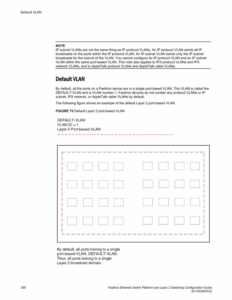
NOTEIP subnet VLANs are not the same thing as IP protocol VLANs. An IP protocol VLAN sends all IPbroadcasts on the ports within the IP protocol VLAN. An IP subnet VLAN sends only the IP subnetbroadcasts for the subnet of the VLAN. You cannot configure an IP protocol VLAN and an IP subnetVLAN within the same port-based VLAN. This note also applies to IPX protocol VLANs and IPXnetwork VLANs, and to AppleTalk protocol VLANs and AppleTalk cable VLANs.
Default VLANBy default, all the ports on a FastIron device are in a single port-based VLAN. This VLAN is called theDEFAULT-VLAN and is VLAN number 1. FastIron devices do not contain any protocol VLANs or IPsubnet, IPX network, or AppleTalk cable VLANs by default.
The following figure shows an example of the default Layer 2 port-based VLAN.
FIGURE 75 Default Layer 2 port-based VLAN
Default VLAN
356 FastIron Ethernet Switch Platform and Layer 2 Switching Configuration Guide53-1003628-03
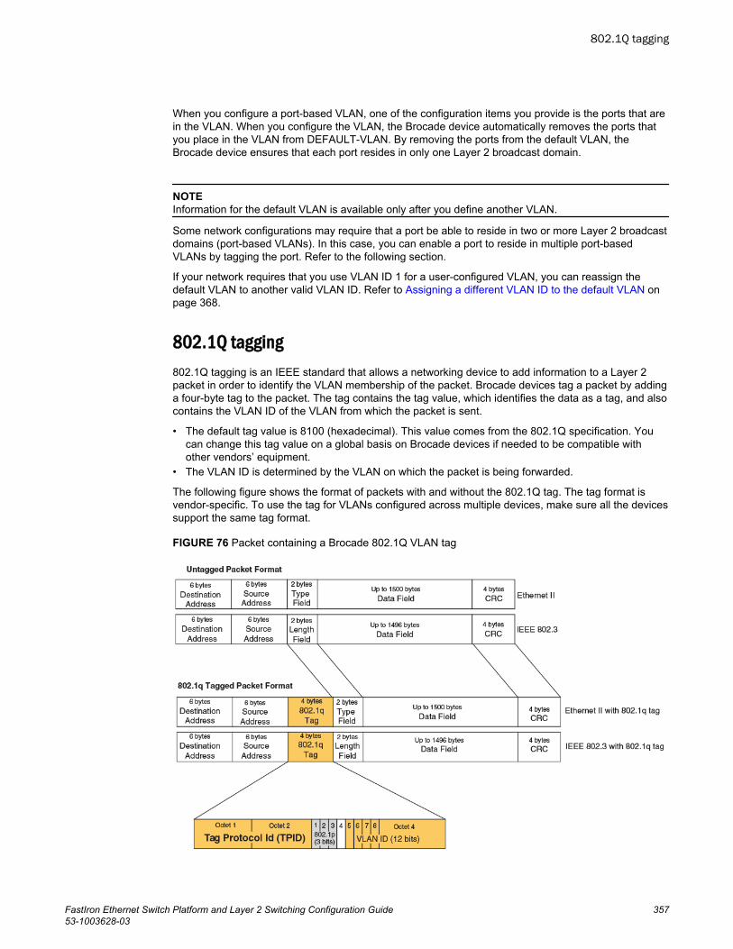
When you configure a port-based VLAN, one of the configuration items you provide is the ports that arein the VLAN. When you configure the VLAN, the Brocade device automatically removes the ports thatyou place in the VLAN from DEFAULT-VLAN. By removing the ports from the default VLAN, theBrocade device ensures that each port resides in only one Layer 2 broadcast domain.
NOTEInformation for the default VLAN is available only after you define another VLAN.
Some network configurations may require that a port be able to reside in two or more Layer 2 broadcastdomains (port-based VLANs). In this case, you can enable a port to reside in multiple port-basedVLANs by tagging the port. Refer to the following section.
If your network requires that you use VLAN ID 1 for a user-configured VLAN, you can reassign thedefault VLAN to another valid VLAN ID. Refer to Assigning a different VLAN ID to the default VLAN onpage 368.
802.1Q tagging802.1Q tagging is an IEEE standard that allows a networking device to add information to a Layer 2packet in order to identify the VLAN membership of the packet. Brocade devices tag a packet by addinga four-byte tag to the packet. The tag contains the tag value, which identifies the data as a tag, and alsocontains the VLAN ID of the VLAN from which the packet is sent.
• The default tag value is 8100 (hexadecimal). This value comes from the 802.1Q specification. Youcan change this tag value on a global basis on Brocade devices if needed to be compatible withother vendors’ equipment.
• The VLAN ID is determined by the VLAN on which the packet is being forwarded.
The following figure shows the format of packets with and without the 802.1Q tag. The tag format isvendor-specific. To use the tag for VLANs configured across multiple devices, make sure all the devicessupport the same tag format.
FIGURE 76 Packet containing a Brocade 802.1Q VLAN tag
802.1Q tagging
FastIron Ethernet Switch Platform and Layer 2 Switching Configuration Guide 35753-1003628-03
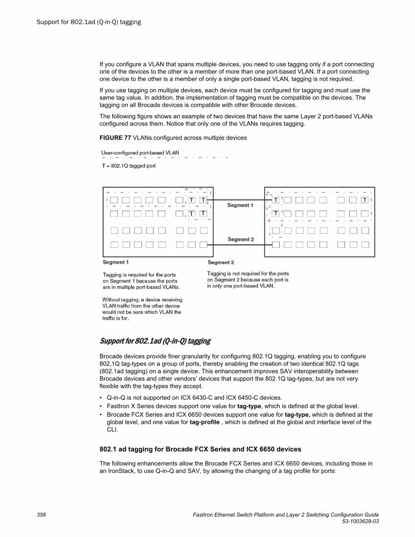
If you configure a VLAN that spans multiple devices, you need to use tagging only if a port connectingone of the devices to the other is a member of more than one port-based VLAN. If a port connectingone device to the other is a member of only a single port-based VLAN, tagging is not required.
If you use tagging on multiple devices, each device must be configured for tagging and must use thesame tag value. In addition, the implementation of tagging must be compatible on the devices. Thetagging on all Brocade devices is compatible with other Brocade devices.
The following figure shows an example of two devices that have the same Layer 2 port-based VLANsconfigured across them. Notice that only one of the VLANs requires tagging.
FIGURE 77 VLANs configured across multiple devices
Support for 802.1ad (Q-in-Q) tagging
Brocade devices provide finer granularity for configuring 802.1Q tagging, enabling you to configure802.1Q tag-types on a group of ports, thereby enabling the creation of two identical 802.1Q tags(802.1ad tagging) on a single device. This enhancement improves SAV interoperability betweenBrocade devices and other vendors’ devices that support the 802.1Q tag-types, but are not veryflexible with the tag-types they accept.
• Q-in-Q is not supported on ICX 6430-C and ICX 6450-C devices.• FastIron X Series devices support one value for tag-type, which is defined at the global level.• Brocade FCX Series and ICX 6650 devices support one value for tag-type, which is defined at the
global level, and one value for tag-profile , which is defined at the global and interface level of theCLI.
802.1 ad tagging for Brocade FCX Series and ICX 6650 devices
The following enhancements allow the Brocade FCX Series and ICX 6650 devices, including those inan IronStack, to use Q-in-Q and SAV, by allowing the changing of a tag profile for ports:
Support for 802.1ad (Q-in-Q) tagging
358 FastIron Ethernet Switch Platform and Layer 2 Switching Configuration Guide53-1003628-03
• In addition to the default tag type 0x8100, you can now configure one additional global tag profilewith a number from 0xffff.
• Tag profiles on a single port, or a group of ports can be configured to point to the global tag profile.
For example applications and configuration details, refer to 802.1ad tagging configuration on page 401.
To configure a global tag profile, enter the following command in the configuration mode.
device(config)# tag-profile 9500Syntax: [no] tag-profile tag-no
tag-no - the number of the tag, can be 0x8100 (default), or 0xffff
To direct individual ports or on a range of ports to this tag profile, enter commands similar to thefollowing.
device(config)# interface ethernet 1/1/1device(config-if-e1000-1/1/1)# tag-profile enabledevice(config-mif-1/1/1,1/2/1)# tag-profile enable
Spanning Tree Protocol (STP)The default state of STP depends on the device type:
• STP is disabled by default on Brocade Layer 3 Switches.• STP is enabled by default on Brocade Layer 2 Switches.
Also by default, each port-based VLAN has a separate instance of STP. Thus, when STP is globallyenabled, each port-based VLAN on the device runs a separate spanning tree.
You can enable or disable STP on the following levels:
• Globally - Affects all ports on the device.
NOTEIf you configure a port-based VLAN on the device, the VLAN has the same STP state as the defaultSTP state on the device. Thus, on Layer 2 Switches, new VLANs have STP enabled by default. OnLayer 3 Switches, new VLANs have STP disabled by default. You can enable or disable STP in eachVLAN separately. In addition, you can enable or disable STP on individual ports.
• Port-based VLAN - Affects all ports within the specified port-based VLAN.
STP is a Layer 2 protocol. Thus, you cannot enable or disable STP for individual protocol VLANs or forIP subnet, IPX network, or AppleTalk cable VLANs. The STP state of a port-based VLAN containingthese other types of VLANs determines the STP state for all the Layer 2 broadcasts within the port-based VLAN. This is true even though Layer 3 protocol broadcasts are sent on Layer 2 within theVLAN.
It is possible that STP will block one or more ports in a protocol VLAN that uses a virtual routinginterface to route to other VLANs. For IP protocol and IP subnet VLANs, even though some of thephysical ports of the virtual routing interface are blocked, the virtual routing interface can still route solong as at least one port in the virtual routing interface protocol VLAN is not blocked by STP.
If you enable Single STP (SSTP) on the device, the ports in all VLANs on which STP is enabledbecome members of a single spanning tree. The ports in VLANs on which STP is disabled are excludedfrom the single spanning tree.
For more information, refer to Spanning Tree Protocol on page 247.
Spanning Tree Protocol (STP)
FastIron Ethernet Switch Platform and Layer 2 Switching Configuration Guide 35953-1003628-03
Virtual routing interfacesA virtual routing interface is a logical routing interface that Brocade Layer 3 Switches use to routeLayer 3 protocol traffic between protocol VLANs.
Brocade devices send Layer 3 traffic at Layer 2 within a protocol VLAN. However, Layer 3 traffic fromone protocol VLAN to another must be routed.
If you want the device to be able to send Layer 3 traffic from one protocol VLAN to another, you mustconfigure a virtual routing interface on each protocol VLAN, then configure routing parameters on thevirtual routing interfaces. For example, to enable a Layer 3 Switch to route IP traffic from one IPsubnet VLAN to another, you must configure a virtual routing interface on each IP subnet VLAN, thenconfigure the appropriate IP routing parameters on each of the virtual routing interfaces.
The following figure shows an example of Layer 3 protocol VLANs that use virtual routing interfaces forrouting.
Virtual routing interfaces
360 FastIron Ethernet Switch Platform and Layer 2 Switching Configuration Guide53-1003628-03
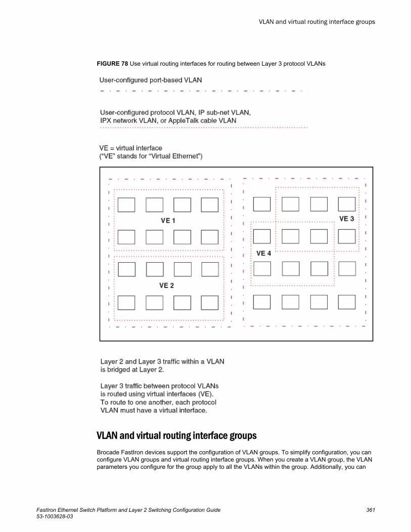
FIGURE 78 Use virtual routing interfaces for routing between Layer 3 protocol VLANs
VLAN and virtual routing interface groupsBrocade FastIron devices support the configuration of VLAN groups. To simplify configuration, you canconfigure VLAN groups and virtual routing interface groups. When you create a VLAN group, the VLANparameters you configure for the group apply to all the VLANs within the group. Additionally, you can
VLAN and virtual routing interface groups
FastIron Ethernet Switch Platform and Layer 2 Switching Configuration Guide 36153-1003628-03
easily associate the same IP subnet interface with all the VLANs in a group by configuring a virtualrouting interface group with the same ID as the VLAN group.
For configuration information, refer to VLAN groups and virtual routing interface group on page 389.
Dynamic, static, and excluded port membershipWhen you add ports to a protocol VLAN, IP subnet VLAN, IPX network VLAN, or AppleTalk cableVLAN, you can add them dynamically or statically:
• Dynamic ports• Static ports
You also can explicitly exclude ports.
Dynamic ports
Dynamic ports are added to a VLAN when you create the VLAN. However, if a dynamically added portdoes not receive any traffic for the VLAN protocol within ten minutes, the port is removed from theVLAN. However, the port remains a candidate for port membership. Thus, if the port receives traffic forthe VLAN protocol, the device adds the port back to the VLAN.
After the port is added back to the VLAN, the port can remain an active member of the VLAN up to 20minutes without receiving traffic for the VLAN protocol. If the port ages out, it remains a candidate forVLAN membership and is added back to the VLAN when the VLAN receives protocol traffic. At thispoint, the port can remain in the VLAN up to 20 minutes without receiving traffic for the VLAN protocol,and so on.
Unless you explicitly add a port statically or exclude a port, the port is a dynamic port and thus can bean active member of the VLAN, depending on the traffic it receives.
NOTEYou cannot configure dynamic ports in an AppleTalk cable VLAN. The ports in an AppleTalk cableVLAN must be static. However, ports in an AppleTalk protocol VLAN can be dynamic or static.
The following figure shows an example of a VLAN with dynamic ports. Dynamic ports not only join andleave the VLAN according to traffic, but also allow some broadcast packets of the specific protocol to"leak" through the VLAN. Refer to Broadcast leaks on page 365.
Dynamic, static, and excluded port membership
362 FastIron Ethernet Switch Platform and Layer 2 Switching Configuration Guide53-1003628-03
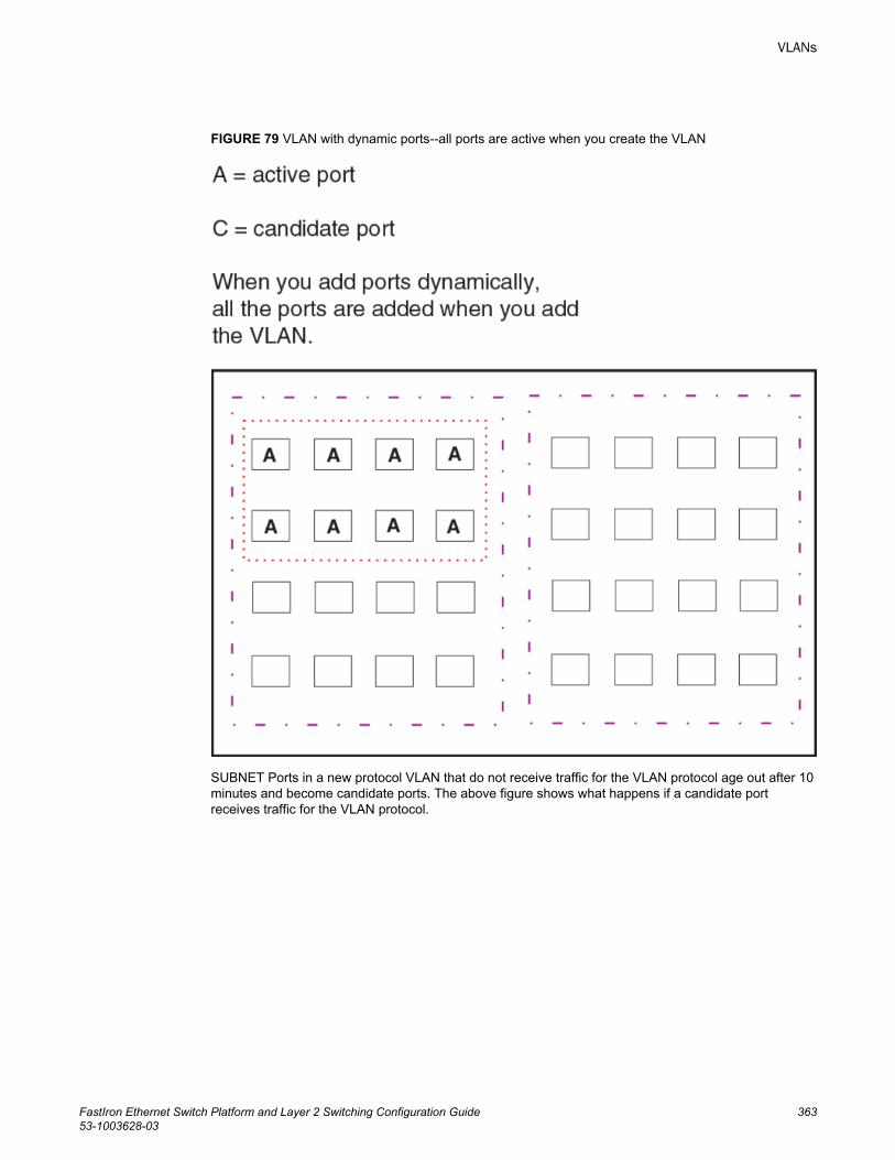
FIGURE 79 VLAN with dynamic ports--all ports are active when you create the VLAN
SUBNET Ports in a new protocol VLAN that do not receive traffic for the VLAN protocol age out after 10minutes and become candidate ports. The above figure shows what happens if a candidate portreceives traffic for the VLAN protocol.
VLANs
FastIron Ethernet Switch Platform and Layer 2 Switching Configuration Guide 36353-1003628-03
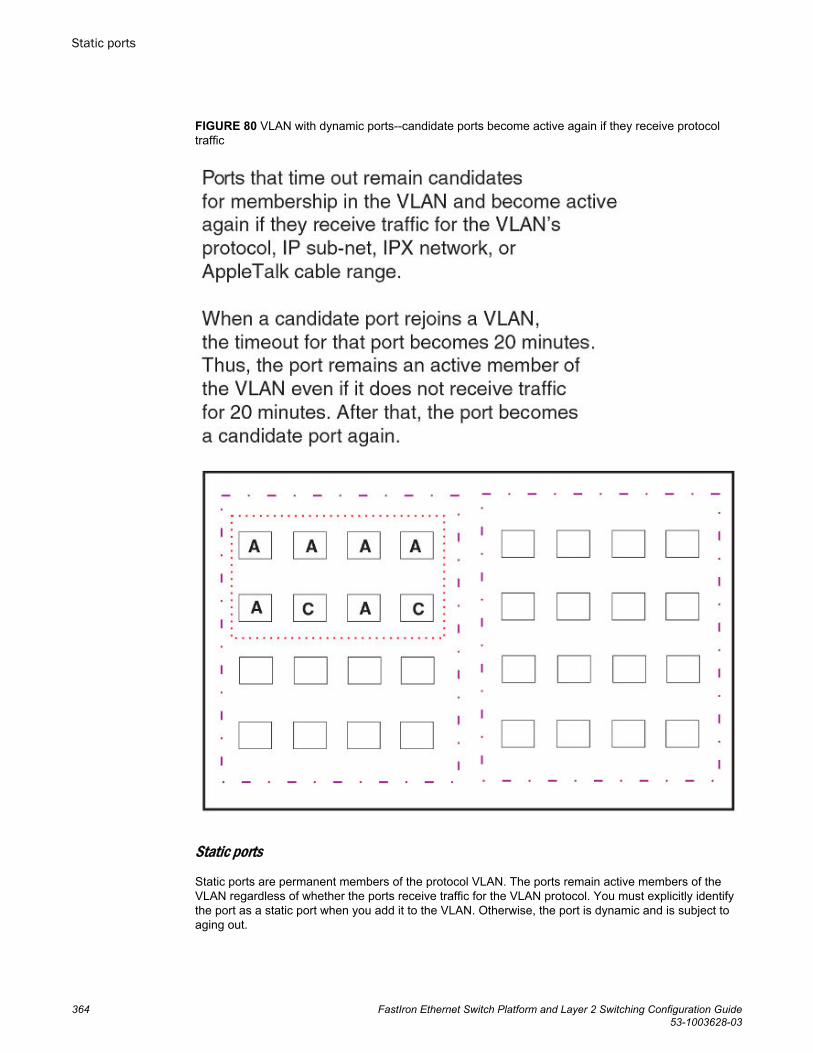
FIGURE 80 VLAN with dynamic ports--candidate ports become active again if they receive protocoltraffic
Static ports
Static ports are permanent members of the protocol VLAN. The ports remain active members of theVLAN regardless of whether the ports receive traffic for the VLAN protocol. You must explicitly identifythe port as a static port when you add it to the VLAN. Otherwise, the port is dynamic and is subject toaging out.
Static ports
364 FastIron Ethernet Switch Platform and Layer 2 Switching Configuration Guide53-1003628-03
Excluded ports
If you want to prevent a port in a port-based VLAN from ever becoming a member of a protocol, IPsubnet, IPX network, or AppleTalk cable VLAN configured in the port-based VLAN, you can explicitlyexclude the port. You exclude the port when you configure the protocol, IP subnet, IPX network, orAppleTalk cable VLAN.
Excluded ports do not leak broadcast packets. Refer to Broadcast leaks on page 365.
Broadcast leaks
A dynamic port becomes a member of a Layer 3 protocol VLAN when traffic from the VLAN's protocol isreceived on the port. After this point, the port remains an active member of the protocol VLAN, unlessthe port does not receive traffic from the VLAN's protocol for 20 minutes. If the port does not receivetraffic for the VLAN's protocol for 20 minutes, the port ages out and is no longer an active member ofthe VLAN.
To enable a host that has been silent for awhile to send and receive packets, the dynamic ports that arecurrently members of the Layer 3 protocol VLAN "leak" Layer 3 broadcast packets to the ports that haveaged out. When a host connected to one of the aged out ports responds to a leaked broadcast, the portis added to the protocol VLAN again.
To "leak" Layer 3 broadcast traffic, an active port sends 1/8th of the Layer 3 broadcast traffic to theinactive (aged out) ports.
Static ports do not age out and do not leak broadcast packets.
Super aggregated VLANsBrocade FastIron devices support Super Aggregated VLANs. You can aggregate multiple VLANs withinanother VLAN. This feature allows you to construct Layer 2 paths and channels. This feature isparticularly useful for Virtual Private Network (VPN) applications in which you need to provide a private,dedicated Ethernet connection for an individual client to transparently reach its subnet across multiplenetworks.
For an application example and configuration information, refer to Super-aggregated VLANconfiguration on page 394.
Trunk group ports and VLAN membershipA trunk group is a set of physical ports that are configured to act as a single physical interface. Eachtrunk group port configuration is based on the configuration of the lead port, which is the lowestnumbered port in the group.
If you add a trunk group lead port to a VLAN, all of the ports in the trunk group become members of thatVLAN.
Summary of VLAN configuration rulesA hierarchy of VLANs exists between the Layer 2 and Layer 3 protocol-based VLANs:
• Port-based VLANs are at the lowest level of the hierarchy.• Layer 3 protocol-based VLANs, IP, IPv6, IPX, AppleTalk, Decnet, and NetBIOS are at the middle
level of the hierarchy.• IP subnet, IPX network, and AppleTalk cable VLANs are at the top of the hierarchy.
Excluded ports
FastIron Ethernet Switch Platform and Layer 2 Switching Configuration Guide 36553-1003628-03
NOTEYou cannot have a protocol-based VLAN and a subnet or network VLAN of the same protocol type inthe same port-based VLAN. For example, you can have an IPX protocol VLAN and IP subnet VLAN inthe same port-based VLAN, but you cannot have an IP protocol VLAN and an IP subnet VLAN in thesame port-based VLAN, nor can you have an IPX protocol VLAN and an IPX network VLAN in thesame port-based VLAN.
As a Brocade device receives packets, the VLAN classification starts from the highest level VLAN first.Therefore, if an interface is configured as a member of both a port-based VLAN and an IP protocolVLAN, IP packets coming into the interface are classified as members of the IP protocol VLANbecause that VLAN is higher in the VLAN hierarchy.
Multiple VLAN membership rules
• A port can belong to multiple, unique, overlapping Layer 3 protocol-based VLANs without VLANtagging.
• A port can belong to multiple, overlapping Layer 2 port-based VLANs only if the port is a taggedport. Packets sent out of a tagged port use an 802.1Q-tagged frame.
• When both port and protocol-based VLANs are configured on a given device, all protocol VLANsmust be strictly contained within a port-based VLAN. A protocol VLAN cannot include ports frommultiple port-based VLANs. This rule is required to ensure that port-based VLANs remain loop-freeLayer 2 broadcast domains.
• IP protocol VLANs and IP subnet VLANs cannot operate concurrently on the system or within thesame port-based VLAN.
• IPX protocol VLANs and IPX network VLANs cannot operate concurrently on the system or withinthe same port-based VLAN.
• If you first configure IP and IPX protocol VLANs before deciding to partition the network by IPsubnet and IPX network VLANs, then you need to delete those VLANs before creating the IPsubnet and IPX network VLANs.
• One of each type of protocol VLAN is configurable within each port-based VLAN on the Layer 2Switch.
• Multiple IP subnet and IPX network VLANs are configurable within each port-based VLAN on theLayer 2 Switch.
• Removing a configured port-based VLAN from a Brocade Communication Systems, Inc Layer 2Switch or Layer 3 Switch automatically removes any protocol-based VLAN, IP subnet VLAN,AppleTalk cable VLAN, or IPX network VLAN, or any Virtual Ethernet router interfaces definedwithin the Port-based VLAN.
Routing between VLANsBrocade Layer 3 Switches can locally route IP, IPX, and Appletalk between VLANs defined within asingle router. All other routable protocols or protocol VLANs (for example, DecNet) must be routed byanother external router capable of routing the protocol.
Virtual routing interfaces (Layer 2 Switches only)You need to configure virtual routing interfaces if an IP, IPX, or Appletalk protocol VLAN, IP subnetVLAN, AppleTalk cable VLAN, or IPX network VLAN needs to route protocols to another port-based
Multiple VLAN membership rules
366 FastIron Ethernet Switch Platform and Layer 2 Switching Configuration Guide53-1003628-03
VLAN on the same router. A virtual routing interface can be associated with the ports in only a singleport-based VLAN. Virtual router interfaces must be defined at the highest level of the VLAN hierarchy.
If you do not need to further partition the port-based VLAN by defining separate Layer 3 VLANs, youcan define a single virtual routing interface at the port-based VLAN level and enable IP, IPX, andAppletalk routing on a single virtual routing interface.
Some configurations may require simultaneous switching and routing of the same single protocol acrossdifferent sets of ports on the same router. When IP, IPX, or Appletalk routing is enabled on a BrocadeLayer 3 Switch, you can route these protocols on specific interfaces while bridging them on otherinterfaces. In this scenario, you can create two separate backbones for the same protocol, one bridgedand one routed.
To bridge IP, IPX, or Appletalk at the same time these protocols are being routed, you need to configurean IP protocol, IP subnet, IPX protocol, IPX network, or Appletalk protocol VLAN and not assign avirtual routing interface to the VLAN. Packets for these protocols are bridged or switched at Layer 2across ports on the router that are included in the Layer 3 VLAN. If these VLANs are built within port-based VLANs, they can be tagged across a single set of backbone fibers to create separate Layer 2switched and Layer 3 routed backbones for the same protocol on a single physical backbone.
Routing between VLANs using virtual routing interfaces (Layer 3Switches only)Brocade calls the ability to route between VLANs with virtual routing interfaces Integrated SwitchRouting (ISR) . There are some important concepts to understand before designing an ISR backbone.
Virtual router interfaces can be defined on port-based, IP protocol, IP subnet, IPX protocol, IPX network,AppleTalk protocol, and AppleTalk cable VLANs.
To create any type of VLAN on a Brocade Layer 3 Switch, Layer 2 forwarding must be enabled. WhenLayer 2 forwarding is enabled, the Layer 3 Switch becomes a Switch on all ports for all non-routableprotocols.
If the router interfaces for IP, IPX, or AppleTalk are configured on physical ports, then routing occursindependent of the Spanning Tree Protocol (STP). However, if the router interfaces are defined for anytype VLAN, they are virtual routing interfaces and are subject to the rules of STP.
If your backbone consists of virtual routing interfaces all within the same STP domain, it is a bridgedbackbone, not a routed one. This means that the set of backbone interfaces that are blocked by STPwill be blocked for routed protocols as well. The routed protocols will be able to cross these paths onlywhen the STP state of the link is FORWARDING. This problem is easily avoided by proper networkdesign.
When designing an ISR network, pay attention to your use of virtual routing interfaces and thespanning-tree domain. If Layer 2 switching of your routed protocols (IP, IPX, AppleTalk) is not requiredacross the backbone, then the use of virtual routing interfaces can be limited to edge switch ports withineach router. Full backbone routing can be achieved by configuring routing on each physical interfacethat connects to the backbone. Routing is independent of STP when configured on a physical interface.
If your ISR design requires that you switch IP, IPX, or Appletalk at Layer 2 while simultaneously routingthe same protocols over a single backbone, then create multiple port-based VLANs and use VLANtagging on the backbone links to separate your Layer 2 switched and Layer 3 routed networks.
There is a separate STP domain for each port-based VLAN. Routing occurs independently across port-based VLANs or STP domains. You can define each end of each backbone link as a separate taggedport-based VLAN. Routing will occur independently across the port-based VLANs. Because each port-based VLAN STP domain is a single point-to-point backbone connection, you are guaranteed to neverhave an STP loop. STP will never block the virtual router interfaces within the tagged port-based VLAN,and you will have a fully routed backbone.
Routing between VLANs using virtual routing interfaces (Layer 3 Switches only)
FastIron Ethernet Switch Platform and Layer 2 Switching Configuration Guide 36753-1003628-03
Dynamic port assignment (Layer 2 Switches and Layer 3 Switches)All Switch ports are dynamically assigned to any Layer 3 VLAN on Brocade Layer 2 Switches and anynon-routable VLAN on Brocade Layer 3 Switches. To maintain explicit control of the VLAN, you canexplicitly exclude ports when configuring any Layer 3 VLAN on a Brocade Layer 2 Switch or any non-routable Layer 3 VLAN on a Brocade Layer 3 Switch.
If you do not want the ports to have dynamic membership, you can add them statically. This eliminatesthe need to explicitly exclude the ports that you do not want to participate in a particular Layer 3 VLAN.
Assigning a different VLAN ID to the default VLANWhen you enable port-based VLANs, all ports in the system are added to the default VLAN. Bydefault, the default VLAN ID is "VLAN 1". The default VLAN is not configurable. If you want to use theVLAN ID "VLAN 1" as a configurable VLAN, you can assign a different VLAN ID to the default VLAN.
To reassign the default VLAN to a different VLAN ID, enter the following command.
device(config)# default-vlan-id 4095Syntax: [no] default-vlan-id vlan-id
You must specify a valid VLAN ID that is not already in use. For example, if you have already definedVLAN 10, do not try to use "10" as the new VLAN ID for the default VLAN. Valid VLAN IDs arenumbers from 1 - 4095.
NOTEThis command does not change the properties of the default VLAN. Changing the name allows you touse the VLAN ID "1" as a configurable VLAN.
Assigning different VLAN IDs to reserved VLANs 4091 and 4092If you want to use VLANs 4091 and 4092 as configurable VLANs, you can assign them to differentVLAN IDs.
For example, to reassign reserved VLAN 4091 to VLAN 10, enter the following commands.
device(config)# reserved-vlan-map vlan 4091 new-vlan 10Reload required. Please write memory and then reload or power cycle.device(config)# write memdevice(config)# exitdevice# reload
NOTEYou must save the configuration (write mem) and reload the software to place the change into effect.
The above configuration changes the VLAN ID of 4091 to 10. After saving the configuration andreloading the software, you can configure VLAN 4091 as you would any other VLAN.
Syntax: [no] reserved-vlan-map vlan 4091 | 4092 new-vlan vlan-id
For vlan-id , enter a valid VLAN ID that is not already in use. For example, if you have already definedVLAN 20, do not try to use "20 as the new VLAN ID. Valid VLAN IDs are numbers from 1 - 4090, 4093,and 4095. VLAN ID 4094 is reserved for use by the Single Spanning Tree feature.
Dynamic port assignment (Layer 2 Switches and Layer 3 Switches)
368 FastIron Ethernet Switch Platform and Layer 2 Switching Configuration Guide53-1003628-03
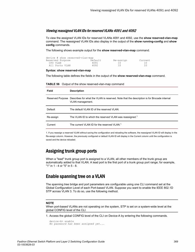
Viewing reassigned VLAN IDs for reserved VLANs 4091 and 4092
To view the assigned VLAN IDs for reserved VLANs 4091 and 4092, use the show reserved-vlan-mapcommand. The reassigned VLAN IDs also display in the output of the show running-config and showconfig commands.
The following shows example output for the show reserved-vlan-map command.
device # show reserved-vlan-mapReserved Purpose Default Re-assign Current CPU VLAN 4091 10 10 All Ports VLAN 4092 33 33Syntax: show reserved-vlan-map
The following table defines the fields in the output of the show reserved-vlan-map command.
Output of the show reserved-vlan-map command TABLE 56
Field Description
Reserved Purpose Describes for what the VLAN is reserved. Note that the description is for Brocade internalVLAN management.
Default The default VLAN ID of the reserved VLAN.
Re-assign The VLAN ID to which the reserved VLAN was reassigned.1
Current The current VLAN ID for the reserved VLAN.1
1. If you reassign a reserved VLAN without saving the configuration and reloading the software, the reassigned VLAN ID will display in theRe-assign column. However, the previously configured or default VLAN ID will display in the Current column until the configuration issaved and the device reloaded.
Assigning trunk group portsWhen a "lead" trunk group port is assigned to a VLAN, all other members of the trunk group areautomatically added to that VLAN. A lead port is the first port of a trunk group port range; for example,"1" in 1 - 4 or "5" in 5 - 8.
Enable spanning tree on a VLANThe spanning tree bridge and port parameters are configurable using one CLI command set at theGlobal Configuration Level of each Port-based VLAN. Suppose you want to enable the IEEE 802.1DSTP across VLAN 3. To do so, use the following method.
NOTEWhen port-based VLANs are not operating on the system, STP is set on a system-wide level at theglobal CONFIG level of the CLI.
1. Access the global CONFIG level of the CLI on Device-A by entering the following commands.
device-A> enableNo password has been assigned yet...
Viewing reassigned VLAN IDs for reserved VLANs 4091 and 4092
FastIron Ethernet Switch Platform and Layer 2 Switching Configuration Guide 36953-1003628-03
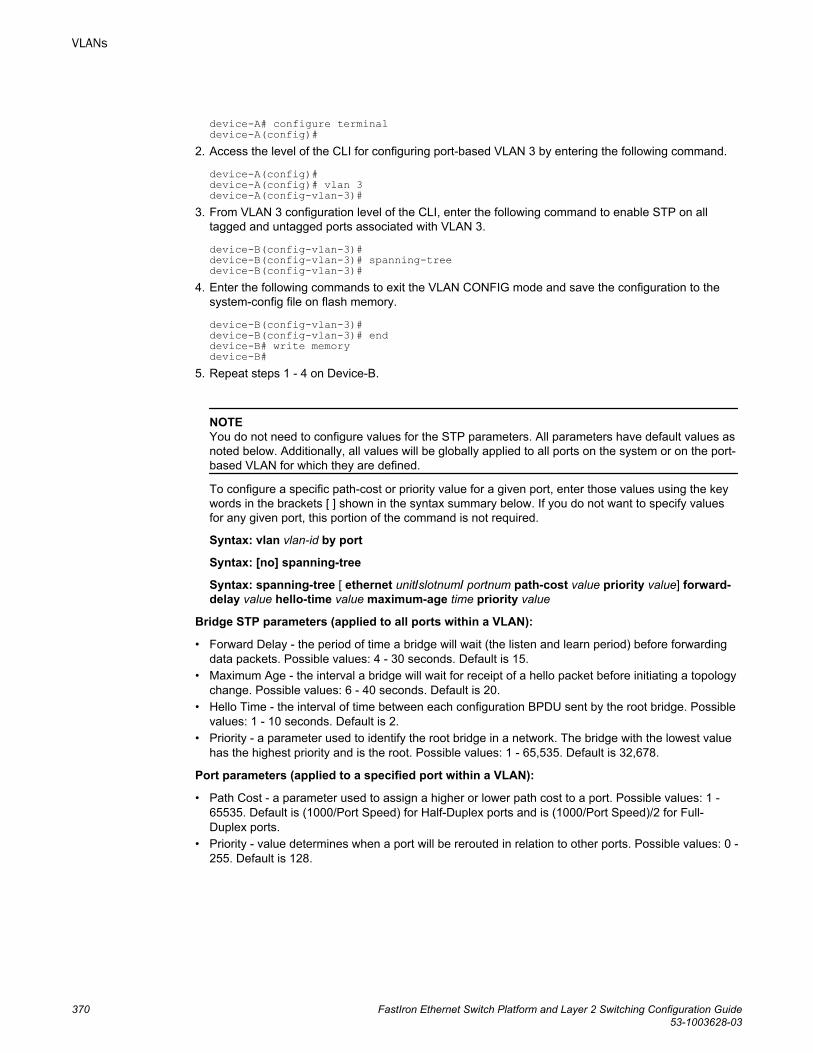
device-A# configure terminaldevice-A(config)#
2. Access the level of the CLI for configuring port-based VLAN 3 by entering the following command.
device-A(config)# device-A(config)# vlan 3device-A(config-vlan-3)#
3. From VLAN 3 configuration level of the CLI, enter the following command to enable STP on alltagged and untagged ports associated with VLAN 3.
device-B(config-vlan-3)# device-B(config-vlan-3)# spanning-treedevice-B(config-vlan-3)#
4. Enter the following commands to exit the VLAN CONFIG mode and save the configuration to thesystem-config file on flash memory.
device-B(config-vlan-3)# device-B(config-vlan-3)# enddevice-B# write memorydevice-B#
5. Repeat steps 1 - 4 on Device-B.
NOTEYou do not need to configure values for the STP parameters. All parameters have default values asnoted below. Additionally, all values will be globally applied to all ports on the system or on the port-based VLAN for which they are defined.
To configure a specific path-cost or priority value for a given port, enter those values using the keywords in the brackets [ ] shown in the syntax summary below. If you do not want to specify valuesfor any given port, this portion of the command is not required.
Syntax: vlan vlan-id by port
Syntax: [no] spanning-tree
Syntax: spanning-tree [ ethernet unit/slotnum/ portnum path-cost value priority value] forward-delay value hello-time value maximum-age time priority value
Bridge STP parameters (applied to all ports within a VLAN):
• Forward Delay - the period of time a bridge will wait (the listen and learn period) before forwardingdata packets. Possible values: 4 - 30 seconds. Default is 15.
• Maximum Age - the interval a bridge will wait for receipt of a hello packet before initiating a topologychange. Possible values: 6 - 40 seconds. Default is 20.
• Hello Time - the interval of time between each configuration BPDU sent by the root bridge. Possiblevalues: 1 - 10 seconds. Default is 2.
• Priority - a parameter used to identify the root bridge in a network. The bridge with the lowest valuehas the highest priority and is the root. Possible values: 1 - 65,535. Default is 32,678.
Port parameters (applied to a specified port within a VLAN):
• Path Cost - a parameter used to assign a higher or lower path cost to a port. Possible values: 1 -65535. Default is (1000/Port Speed) for Half-Duplex ports and is (1000/Port Speed)/2 for Full-Duplex ports.
• Priority - value determines when a port will be rerouted in relation to other ports. Possible values: 0 -255. Default is 128.
VLANs
370 FastIron Ethernet Switch Platform and Layer 2 Switching Configuration Guide53-1003628-03
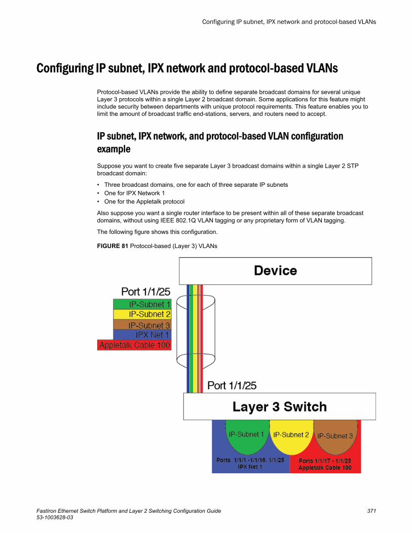
Configuring IP subnet, IPX network and protocol-based VLANsProtocol-based VLANs provide the ability to define separate broadcast domains for several uniqueLayer 3 protocols within a single Layer 2 broadcast domain. Some applications for this feature mightinclude security between departments with unique protocol requirements. This feature enables you tolimit the amount of broadcast traffic end-stations, servers, and routers need to accept.
IP subnet, IPX network, and protocol-based VLAN configurationexampleSuppose you want to create five separate Layer 3 broadcast domains within a single Layer 2 STPbroadcast domain:
• Three broadcast domains, one for each of three separate IP subnets• One for IPX Network 1• One for the Appletalk protocol
Also suppose you want a single router interface to be present within all of these separate broadcastdomains, without using IEEE 802.1Q VLAN tagging or any proprietary form of VLAN tagging.
The following figure shows this configuration.
FIGURE 81 Protocol-based (Layer 3) VLANs
Configuring IP subnet, IPX network and protocol-based VLANs
FastIron Ethernet Switch Platform and Layer 2 Switching Configuration Guide 37153-1003628-03
To configure the VLANs shown in the above figure, use the following procedure.
1. To permanently assign ports 1/1/1 - 1/1/8 and port 1/1/25 to IP subnet VLAN 10.1.1.0, enter thefollowing commands.
device(config-vlan-2)# ip-subnet 10.1.1.0/24 name Greendevice(config-vlan-ip-subnet)# no dynamicdevice(config-vlan-ip-subnet)# static ethernet 1/1/1 to 1/1/8 ethernet 1/1/25
2. To permanently assign ports 1/1/9 - 1/1/16 and port 1/1/25 to IP subnet VLAN 10.1.2.0, enter thefollowing commands.
device(config-vlan-3)# ip-subnet 10.1.2.0/24 name Yellowdevice(config-vlan-ip-subnet)# no dynamicdevice(config-vlan-ip-subnet)# static ethernet 1/1/9 to 1/1/16 ethernet 1/1/25
3. To permanently assign ports 1/1/17 - 1/1/25 to IP subnet VLAN 10.1.3.0, enter the followingcommands.
device(config-vlan-4)# ip-subnet 10.1.3.0/24 name Browndevice(config-vlan-ip-subnet)# no dynamicdevice(config-vlan-ip-subnet)# static ethernet 1/1/17 to 1/1/25
4. To permanently assign ports 1/1/1 - 1/1/12 and port 1/1/25 to IPX network 1 VLAN, enter thefollowing commands.
device(config-ip-subnet)# ipx-network 1 ethernet_802.3 name Bluedevice(config-ipx-network)# no dynamicdevice(config-ipx-network)# static ethernet 1/1/1 to 1/1/12 ethernet 1/1/25device(config-ipx-network)#
5. To permanently assign ports 1/1/12 - 1/1/25 to Appletalk VLAN, enter the following commands.
device(config-ipx-proto)# atalk-proto name Reddevice(config-atalk-proto)# no dynamicdevice(config-atalk-proto)# static ethernet 1/1/13 to 1/1/25device(config-atalk-proto)# enddevice# write memorydevice# Syntax: ip-subnet ip-addr ip-mask [ name string]
Syntax: ipx-network ipx-network-number frame-encapsulation-type netbios-allow | netbios-disallow [ name string]
Syntax: ip-proto | ipx-proto | atalk-proto | decnet-proto | netbios-proto | other-proto static |exclude | dynamic ethernet unit/slotnum/portnum [ to unit/slotnum/portnum] [name string]
IP subnet, IPX network, and protocol-based VLANs within port-basedVLANs
If you plan to use port-based VLANs in conjunction with protocol-based VLANs, you must create theport-based VLANs first. Once you create a port-based VLAN, then you can assign Layer 3 protocolVLANs within the boundaries of the port-based VLAN. Generally, you create port-based VLANs toallow multiple separate STP domains.
Suppose you need to provide three separate STP domains across an enterprise campus backbone.The first STP domain (VLAN 2) requires a set of ports at each Layer 2 Switch location to be staticallymapped to IP only. No other protocols can enter the switches on this set of ports.
A second set of ports within STP domain VLAN 2 will be restricted to only IPX traffic. The IP and IPXprotocol VLANs will overlap on Port 1 of Device-A to support both protocols on the same routerinterface. The IP subnets and IPX network that span the two protocol VLANs will be determined by the
IP subnet, IPX network, and protocol-based VLANs within port-based VLANs
372 FastIron Ethernet Switch Platform and Layer 2 Switching Configuration Guide53-1003628-03
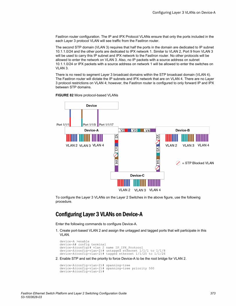
FastIron router configuration. The IP and IPX Protocol VLANs ensure that only the ports included in theeach Layer 3 protocol VLAN will see traffic from the FastIron router.
The second STP domain (VLAN 3) requires that half the ports in the domain are dedicated to IP subnet10.1.1.0/24 and the other ports are dedicated to IPX network 1. Similar to VLAN 2, Port 9 from VLAN 3will be used to carry this IP subnet and IPX network to the FastIron router. No other protocols will beallowed to enter the network on VLAN 3. Also, no IP packets with a source address on subnet10.1.1.0/24 or IPX packets with a source address on network 1 will be allowed to enter the switches onVLAN 3.
There is no need to segment Layer 3 broadcast domains within the STP broadcast domain (VLAN 4).The FastIron router will dictate the IP subnets and IPX network that are on VLAN 4. There are no Layer3 protocol restrictions on VLAN 4; however, the FastIron router is configured to only forward IP and IPXbetween STP domains.
FIGURE 82 More protocol-based VLANs
To configure the Layer 3 VLANs on the Layer 2 Switches in the above figure, use the followingprocedure.
Configuring Layer 3 VLANs on Device-AEnter the following commands to configure Device-A.
1. Create port-based VLAN 2 and assign the untagged and tagged ports that will participate in thisVLAN.
device-A >enabledevice-A# config terminaldevice-A(config)# vlan 2 name IP_IPX_Protocoldevice-A(config-vlan-2)# untagged ethernet 1/1/1 to 1/1/8device-A(config-vlan-2)# tagged ethernet 1/1/25 to 1/1/26
2. Enable STP and set the priority to force Device-A to be the root bridge for VLAN 2.
device-A(config-vlan-2)# spanning-treedevice-A(config-vlan-2)# spanning-tree priority 500device-A(config-vlan-2)#
Configuring Layer 3 VLANs on Device-A
FastIron Ethernet Switch Platform and Layer 2 Switching Configuration Guide 37353-1003628-03
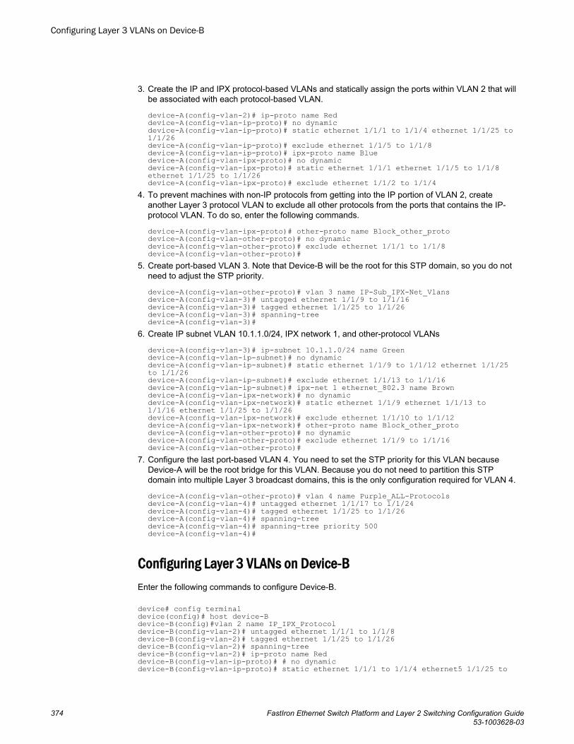
3. Create the IP and IPX protocol-based VLANs and statically assign the ports within VLAN 2 that willbe associated with each protocol-based VLAN.
device-A(config-vlan-2)# ip-proto name Reddevice-A(config-vlan-ip-proto)# no dynamicdevice-A(config-vlan-ip-proto)# static ethernet 1/1/1 to 1/1/4 ethernet 1/1/25 to 1/1/26device-A(config-vlan-ip-proto)# exclude ethernet 1/1/5 to 1/1/8device-A(config-vlan-ip-proto)# ipx-proto name Bluedevice-A(config-vlan-ipx-proto)# no dynamicdevice-A(config-vlan-ipx-proto)# static ethernet 1/1/1 ethernet 1/1/5 to 1/1/8 ethernet 1/1/25 to 1/1/26device-A(config-vlan-ipx-proto)# exclude ethernet 1/1/2 to 1/1/4
4. To prevent machines with non-IP protocols from getting into the IP portion of VLAN 2, createanother Layer 3 protocol VLAN to exclude all other protocols from the ports that contains the IP-protocol VLAN. To do so, enter the following commands.
device-A(config-vlan-ipx-proto)# other-proto name Block_other_protodevice-A(config-vlan-other-proto)# no dynamicdevice-A(config-vlan-other-proto)# exclude ethernet 1/1/1 to 1/1/8device-A(config-vlan-other-proto)#
5. Create port-based VLAN 3. Note that Device-B will be the root for this STP domain, so you do notneed to adjust the STP priority.
device-A(config-vlan-other-proto)# vlan 3 name IP-Sub_IPX-Net_Vlansdevice-A(config-vlan-3)# untagged ethernet 1/1/9 to 1/1/16device-A(config-vlan-3)# tagged ethernet 1/1/25 to 1/1/26device-A(config-vlan-3)# spanning-treedevice-A(config-vlan-3)#
6. Create IP subnet VLAN 10.1.1.0/24, IPX network 1, and other-protocol VLANs
device-A(config-vlan-3)# ip-subnet 10.1.1.0/24 name Greendevice-A(config-vlan-ip-subnet)# no dynamicdevice-A(config-vlan-ip-subnet)# static ethernet 1/1/9 to 1/1/12 ethernet 1/1/25 to 1/1/26device-A(config-vlan-ip-subnet)# exclude ethernet 1/1/13 to 1/1/16device-A(config-vlan-ip-subnet)# ipx-net 1 ethernet_802.3 name Browndevice-A(config-vlan-ipx-network)# no dynamicdevice-A(config-vlan-ipx-network)# static ethernet 1/1/9 ethernet 1/1/13 to 1/1/16 ethernet 1/1/25 to 1/1/26device-A(config-vlan-ipx-network)# exclude ethernet 1/1/10 to 1/1/12device-A(config-vlan-ipx-network)# other-proto name Block_other_protodevice-A(config-vlan-other-proto)# no dynamicdevice-A(config-vlan-other-proto)# exclude ethernet 1/1/9 to 1/1/16device-A(config-vlan-other-proto)#
7. Configure the last port-based VLAN 4. You need to set the STP priority for this VLAN becauseDevice-A will be the root bridge for this VLAN. Because you do not need to partition this STPdomain into multiple Layer 3 broadcast domains, this is the only configuration required for VLAN 4.
device-A(config-vlan-other-proto)# vlan 4 name Purple_ALL-Protocolsdevice-A(config-vlan-4)# untagged ethernet 1/1/17 to 1/1/24device-A(config-vlan-4)# tagged ethernet 1/1/25 to 1/1/26device-A(config-vlan-4)# spanning-treedevice-A(config-vlan-4)# spanning-tree priority 500device-A(config-vlan-4)#
Configuring Layer 3 VLANs on Device-BEnter the following commands to configure Device-B.
device# config terminaldevice(config)# host device-Bdevice-B(config)#vlan 2 name IP_IPX_Protocoldevice-B(config-vlan-2)# untagged ethernet 1/1/1 to 1/1/8device-B(config-vlan-2)# tagged ethernet 1/1/25 to 1/1/26device-B(config-vlan-2)# spanning-treedevice-B(config-vlan-2)# ip-proto name Reddevice-B(config-vlan-ip-proto)# # no dynamicdevice-B(config-vlan-ip-proto)# static ethernet 1/1/1 to 1/1/4 ethernet5 1/1/25 to
Configuring Layer 3 VLANs on Device-B
374 FastIron Ethernet Switch Platform and Layer 2 Switching Configuration Guide53-1003628-03
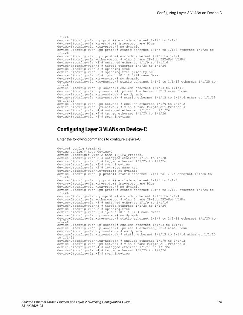
1/1/26device-B(config-vlan-ip-proto)# exclude ethernet 1/1/5 to 1/1/8device-B(config-vlan-ip-proto)# ipx-proto name Bluedevice-B(config-vlan-ipx-proto)# no dynamicdevice-B(config-vlan-ipx-proto)# static ethernet 1/1/5 to 1/1/8 ethernet 1/1/25 to 1/1/26device-B(config-vlan-ipx-proto)# exclude ethernet 1/1/1 to 1/1/4device-B(config-vlan-other-proto)# vlan 3 name IP-Sub_IPX-Net_VLANsdevice-B(config-vlan-3)# untagged ethernet 1/1/9 to 1/1/16device-B(config-vlan-3)# tagged ethernet 1/1/25 to 1/1/26device-B(config-vlan-3)# spanning-treedevice-B(config-vlan-3)# spanning-tree priority 500device-B(config-vlan-3)# ip-sub 10.1.1.0/24 name Greendevice-B(config-vlan-ip-subnet)# no dynamicdevice-B(config-vlan-ip-subnet)# static ethernet 1/1/9 to 1/1/12 ethernet 1/1/25 to 1/1/26device-B(config-vlan-ip-subnet)# exclude ethernet 1/1/13 to 1/1/16device-B(config-vlan-ip-subnet)# ipx-net 1 ethernet_802.3 name Browndevice-B(config-vlan-ipx-network)# no dynamicdevice-B(config-vlan-ipx-network)# static ethernet 1/1/13 to 1/1/16 ethernet 1/1/25 to 1/1/26device-B(config-vlan-ipx-network)# exclude ethernet 1/1/9 to 1/1/12device-B(config-vlan-ipx-network)# vlan 4 name Purple_ALL-Protocolsdevice-B(config-vlan-4)# untagged ethernet 1/1/17 to 1/1/24device-B(config-vlan-4)# tagged ethernet 1/1/25 to 1/1/26device-B(config-vlan-4)# spanning-tree
Configuring Layer 3 VLANs on Device-CEnter the following commands to configure Device-C.
device# config terminaldevice(config)# host device-Cdevice-C(config)# vlan 2 name IP_IPX_Protocoldevice-C(config-vlan-2)# untagged ethernet 1/1/1 to 1/1/8device-C(config-vlan-2)# tagged ethernet 1/1/25 to 1/1/26device-C(config-vlan-2)# spanning-treedevice-C(config-vlan-2)# ip-proto name Reddevice-C(config-vlan-ip-proto)# no dynamicdevice-C(config-vlan-ip-proto)# static ethernet 1/1/1 to 1/1/4 ethernet 1/1/25 to 1/1/26device-C(config-vlan-ip-proto)# exclude ethernet 1/1/5 to 1/1/8device-C(config-vlan-ip-proto)# ipx-proto name Bluedevice-C(config-vlan-ipx-proto)# no dynamicdevice-C(config-vlan-ipx-proto)# static ethernet 1/1/5 to 1/1/8 ethernet 1/1/25 to 1/1/26device-C(config-vlan-ipx-proto)# exclude ethernet 1/1/1 to 1/1/4device-C(config-vlan-other-proto)# vlan 3 name IP-Sub_IPX-Net_VLANsdevice-C(config-vlan-3)# untagged ethernet 1/1/9 to 1/1/16device-C(config-vlan-3)# tagged ethernet 1/1/25 to 1/1/26device-C(config-vlan-3)# spanning-treedevice-C(config-vlan-3)# ip-sub 10.1.1.0/24 name Greendevice-C(config-vlan-ip-subnet)# no dynamicdevice-C(config-vlan-ip-subnet)# static ethernet 1/1/9 to 1/1/12 ethernet 1/1/25 to 1/1/26device-C(config-vlan-ip-subnet)# exclude ethernet 1/1/13 to 1/1/16device-C(config-vlan-ip-subnet)# ipx-net 1 ethernet_802.3 name Browndevice-C(config-vlan-ipx-network)# no dynamicdevice-C(config-vlan-ipx-network)# static ethernet 1/1/13 to 1/1/16 ethernet 1/1/25 to 1/1/26device-C(config-vlan-ipx-network)# exclude ethernet 1/1/9 to 1/1/12device-C(config-vlan-ipx-network)# vlan 4 name Purple_ALL-Protocolsdevice-C(config-vlan-4)# untagged ethernet 1/1/17 to 1/1/24device-C(config-vlan-4)# tagged ethernet 1/1/25 to 1/1/26device-C(config-vlan-4)# spanning-tree
Configuring Layer 3 VLANs on Device-C
FastIron Ethernet Switch Platform and Layer 2 Switching Configuration Guide 37553-1003628-03
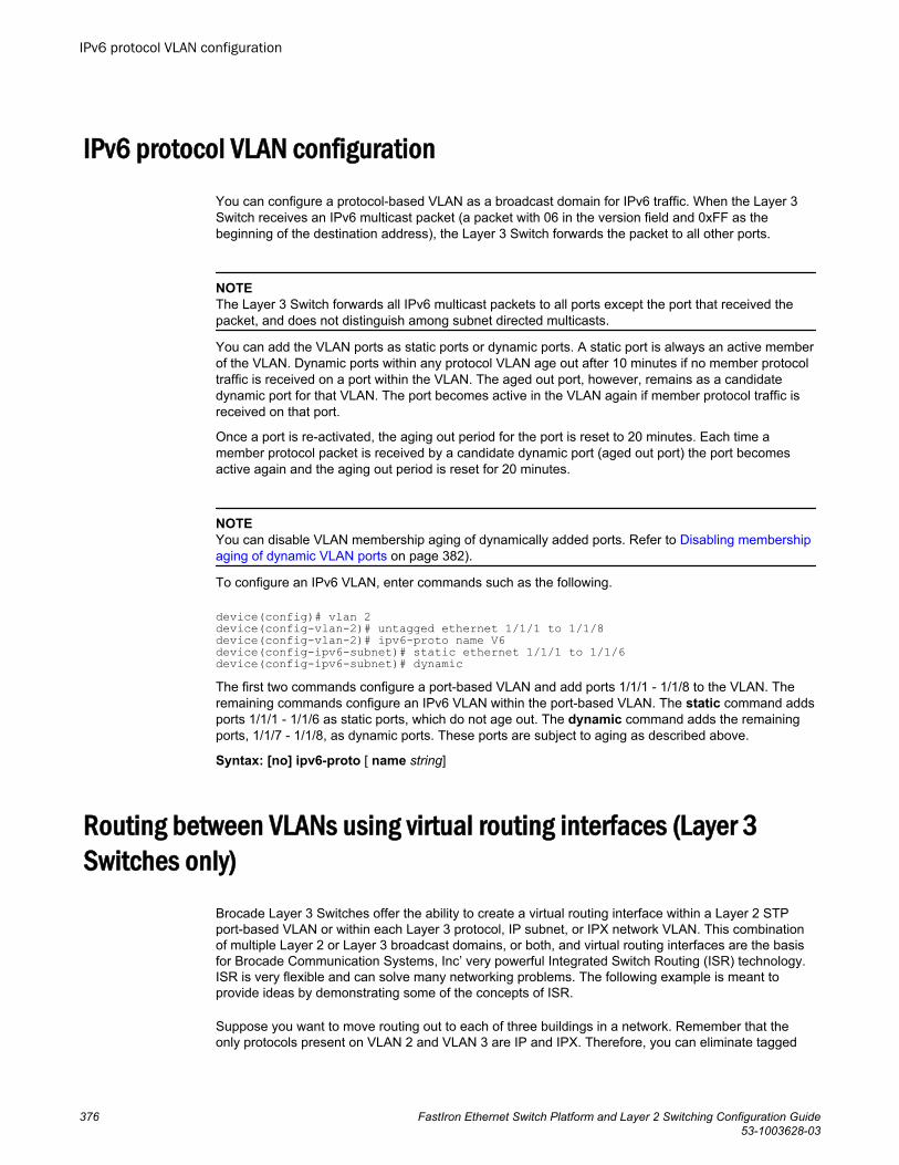
IPv6 protocol VLAN configuration
You can configure a protocol-based VLAN as a broadcast domain for IPv6 traffic. When the Layer 3Switch receives an IPv6 multicast packet (a packet with 06 in the version field and 0xFF as thebeginning of the destination address), the Layer 3 Switch forwards the packet to all other ports.
NOTEThe Layer 3 Switch forwards all IPv6 multicast packets to all ports except the port that received thepacket, and does not distinguish among subnet directed multicasts.
You can add the VLAN ports as static ports or dynamic ports. A static port is always an active memberof the VLAN. Dynamic ports within any protocol VLAN age out after 10 minutes if no member protocoltraffic is received on a port within the VLAN. The aged out port, however, remains as a candidatedynamic port for that VLAN. The port becomes active in the VLAN again if member protocol traffic isreceived on that port.
Once a port is re-activated, the aging out period for the port is reset to 20 minutes. Each time amember protocol packet is received by a candidate dynamic port (aged out port) the port becomesactive again and the aging out period is reset for 20 minutes.
NOTEYou can disable VLAN membership aging of dynamically added ports. Refer to Disabling membershipaging of dynamic VLAN ports on page 382).
To configure an IPv6 VLAN, enter commands such as the following.
device(config)# vlan 2device(config-vlan-2)# untagged ethernet 1/1/1 to 1/1/8device(config-vlan-2)# ipv6-proto name V6device(config-ipv6-subnet)# static ethernet 1/1/1 to 1/1/6device(config-ipv6-subnet)# dynamicThe first two commands configure a port-based VLAN and add ports 1/1/1 - 1/1/8 to the VLAN. Theremaining commands configure an IPv6 VLAN within the port-based VLAN. The static command addsports 1/1/1 - 1/1/6 as static ports, which do not age out. The dynamic command adds the remainingports, 1/1/7 - 1/1/8, as dynamic ports. These ports are subject to aging as described above.
Syntax: [no] ipv6-proto [ name string]
Routing between VLANs using virtual routing interfaces (Layer 3Switches only)
Brocade Layer 3 Switches offer the ability to create a virtual routing interface within a Layer 2 STPport-based VLAN or within each Layer 3 protocol, IP subnet, or IPX network VLAN. This combinationof multiple Layer 2 or Layer 3 broadcast domains, or both, and virtual routing interfaces are the basisfor Brocade Communication Systems, Inc’ very powerful Integrated Switch Routing (ISR) technology.ISR is very flexible and can solve many networking problems. The following example is meant toprovide ideas by demonstrating some of the concepts of ISR.
Suppose you want to move routing out to each of three buildings in a network. Remember that theonly protocols present on VLAN 2 and VLAN 3 are IP and IPX. Therefore, you can eliminate tagged
IPv6 protocol VLAN configuration
376 FastIron Ethernet Switch Platform and Layer 2 Switching Configuration Guide53-1003628-03
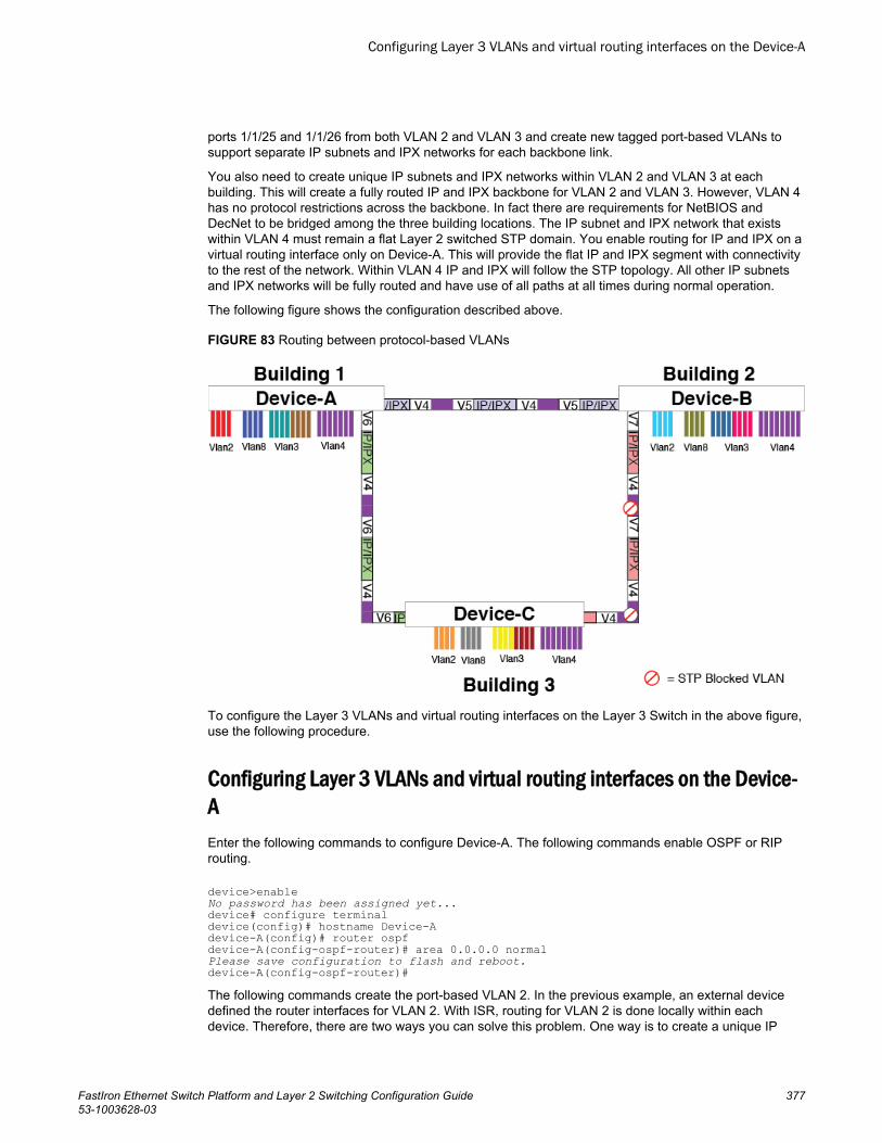
ports 1/1/25 and 1/1/26 from both VLAN 2 and VLAN 3 and create new tagged port-based VLANs tosupport separate IP subnets and IPX networks for each backbone link.
You also need to create unique IP subnets and IPX networks within VLAN 2 and VLAN 3 at eachbuilding. This will create a fully routed IP and IPX backbone for VLAN 2 and VLAN 3. However, VLAN 4has no protocol restrictions across the backbone. In fact there are requirements for NetBIOS andDecNet to be bridged among the three building locations. The IP subnet and IPX network that existswithin VLAN 4 must remain a flat Layer 2 switched STP domain. You enable routing for IP and IPX on avirtual routing interface only on Device-A. This will provide the flat IP and IPX segment with connectivityto the rest of the network. Within VLAN 4 IP and IPX will follow the STP topology. All other IP subnetsand IPX networks will be fully routed and have use of all paths at all times during normal operation.
The following figure shows the configuration described above.
FIGURE 83 Routing between protocol-based VLANs
To configure the Layer 3 VLANs and virtual routing interfaces on the Layer 3 Switch in the above figure,use the following procedure.
Configuring Layer 3 VLANs and virtual routing interfaces on the Device-AEnter the following commands to configure Device-A. The following commands enable OSPF or RIProuting.
device>enableNo password has been assigned yet...device# configure terminaldevice(config)# hostname Device-Adevice-A(config)# router ospfdevice-A(config-ospf-router)# area 0.0.0.0 normalPlease save configuration to flash and reboot.device-A(config-ospf-router)# The following commands create the port-based VLAN 2. In the previous example, an external devicedefined the router interfaces for VLAN 2. With ISR, routing for VLAN 2 is done locally within eachdevice. Therefore, there are two ways you can solve this problem. One way is to create a unique IP
Configuring Layer 3 VLANs and virtual routing interfaces on the Device-A
FastIron Ethernet Switch Platform and Layer 2 Switching Configuration Guide 37753-1003628-03
subnet and IPX network VLAN, each with its own virtual routing interface and unique IP or IPXaddress within VLAN 2 on each device. In this example, this is the configuration used for VLAN 3. Thesecond way is to split VLAN 2 into two separate port-based VLANs and create a virtual router interfacewithin each port-based VLAN. Later in this example, this second option is used to create a port-basedVLAN 8 to show that there are multiple ways to accomplish the same task with ISR.
You also need to create the Other-Protocol VLAN within port-based VLAN 2 and 8 to preventunwanted protocols from being Layer 2 switched within port-based VLAN 2 or 8. Note that the onlyport-based VLAN that requires STP in this example is VLAN 4. You will need to configure the rest ofthe network to prevent the need to run STP.
device-A(config-ospf-router)# vlan 2 name IP-Subnet_10.1.2.0/24device-A(config-vlan-2)# untagged ethernet 1/1/1 to 1/1/4device-A(config-vlan-2)# no spanning-treedevice-A(config-vlan-2)# router-interface ve1device-A(config-vlan-2)# other-proto name block_other_protocolsdevice-A(config-vlan-other-proto)# no dynamicdevice-A(config-vlan-other-proto)# exclude ethernet 1/1/1 to 1/1/4Once you have defined the port-based VLAN and created the virtual routing interface, you need toconfigure the virtual routing interface just as you would configure a physical interface.
device-A(config-vlan-other-proto)# interface ve1device-A(config-vif-1)# ip address 10.1.2.1/24device-A(config-vif-1)# ip ospf area 0.0.0.0Do the same thing for VLAN 8.
device-A(config-vif-1)# vlan 8 name IPX_Network2device-A(config-vlan-8)# untagged ethernet 1/1/5 to 1/1/8device-A(config-vlan-8)# no spanning-treedevice-A(config-vlan-8)# router-interface ve 2device-A(config-vlan-8)# ipx-network 2 ethernet_802.3device-A(config-vlan-8)# other-proto name block-other-protocolsdevice-A(config-vlan-other-proto)# no dynamicdevice-A(config-vlan-other-proto)# exclude ethernet 1/1/5 to 1/1/8device-A(config-vlan-other-proto)# interface ve2device-A(config-vif-1)# ip address 10.1.2.2/24device-A(config-vif-1)# ip ospf area 0.0.0.0The next thing you need to do is create VLAN 3. This is very similar to the previous example with theaddition of virtual routing interfaces to the IP subnet and IPX network VLANs. Also there is no need toexclude ports from the IP subnet and IPX network VLANs on the router.
device-A(config-vif-2)# vlan 3 name IP_Sub_&_IPX_Net_VLANdevice-A(config-vlan-3)# untagged ethernet 1/1/9 to 1/1/16device-A(config-vlan-3)# no spanning-treedevice-A(config-vlan-3)# ip-subnet 10.1.1.0/24device-A(config-vlan-ip-subnet)# static ethernet 1/1/9 to 1/1/12device-A(config-vlan-ip-subnet)# router-interface ve3device-A(config-vlan-ip-subnet)# ipx-network 1 ethernet_802.3device-A(config-vlan-ipx-network)# static ethernet 1/1/13 to 1/1/16device-A(config-vlan-ipx-network)# router-interface ve4device-A(config-vlan-ipx-network)# other-proto name block-other-protocolsdevice-A(config-vlan-other-proto)# exclude ethernet 1/1/9 to 1/1/16device-A(config-vlan-other-proto)# no dynamicdevice-A(config-vlan-other-proto)# interface ve 3device-A(config-vif-3)# ip addr 10.1.1.1/24device-A(config-vif-3)# ip ospf area 0.0.0.0Now configure VLAN 4. Remember this is a flat segment that, in the previous example, obtained its IPdefault gateway and IPX router services from an external device. In this example, Device-A willprovide the routing services for VLAN 4. You also want to configure the STP priority for VLAN 4 tomake Device-A the root bridge for this VLAN.
device-A(config-vif-4)# vlan 4 name Bridged_ALL_Protocolsdevice-A(config-vlan-4)# untagged ethernet 1/1/17 to 1/1/24device-A(config-vlan-4)# tagged ethernet 1/1/25 to 1/1/26device-A(config-vlan-4)# spanning-tree
VLANs
378 FastIron Ethernet Switch Platform and Layer 2 Switching Configuration Guide53-1003628-03
device-A(config-vlan-4)# spanning-tree priority 500device-A(config-vlan-4)# ipx network 3 ethernet_802.3device-A(config-vlan-ipx-network)# exitdevice-A(config-vlan-4)# router-interface ve5device-A(config-vlan-4)# interface ve5device-A(config-vif-5)# ip address 10.1.3.1/24device-A(config-vif-5)# ip ospf area 0.0.0.0It is time to configure a separate port-based VLAN for each of the routed backbone ports (Ethernet1/1/25 and 1/1/26). If you do not create a separate tagged port-based VLAN for each point-to-pointbackbone link, you need to include tagged interfaces for Ethernet 1/1/25 and 1/1/26 within VLANs 2, 3,and 8. This type of configuration makes the entire backbone a single STP domain for each VLAN 2, 3,and 8. This is the configuration used in the example in Configuring IP subnet, IPX network and protocol-based VLANs on page 371. In this scenario, the virtual routing interfaces within port-based VLANs 2, 3,and 8 will be accessible using only one path through the network. The path that is blocked by STP is notavailable to the routing protocols until it is in the STP FORWARDING state.
device-A(config-vif-5)# vlan 5 name Rtr_BB_to_Bldg.2device-A(config-vlan-5)# tagged ethernet 1/1/25device-A(config-vlan-5)# no spanning-treedevice-A(config-vlan-5)# router-interface ve6device-A(config-vlan-5)# vlan 6 name Rtr_BB_to_Bldg.3device-A(config-vlan-6)# tagged ethernet 1/1/26device-A(config-vlan-6)# no spanning-treedevice-A(config-vlan-6)# ipx-network 4 ethernet_802.3device-A(config-vlan-ipx-network)# exitdevice-A(config-vlan-6)# router-interface ve7device-A(config-vlan-6)# interface ve6device-A(config-vif-6)# ip addr 10.1.4.1/24device-A(config-vif-6)# ip ospf area 0.0.0.0device-A(config-vif-6)# interface ve7device-A(config-vif-7)# ip addr 10.1.5.1/24device-A(config-vif-7)# ip ospf area 0.0.0.0device-A(config-vif-7)# This completes the configuration for Device-A. The configuration for Device-B and C is very similarexcept for a few issues which are as follows:
• IP subnets and IPX networks configured on Device-B and Device-C must be unique across the entirenetwork, except for the backbone port-based VLANs 5, 6, and 7 where the subnet is the same butthe IP address must change.
• There is no need to change the default priority of STP within VLAN 4.• There is no need to include a virtual router interface within VLAN 4.• The backbone VLAN between Device-B and Device-C must be the same at both ends and requires a
new VLAN ID. The VLAN ID for this port-based VLAN is VLAN 7.
Configuring Layer 3 VLANs and virtual routing interfaces for Device-BEnter the following commands to configure Device-B.
device> enableNo password has been assigned yet...device# config terminaldevice(config)# hostname Device-Bdevice-B(config)# router ospfdevice-B(config-ospf-router)# area 0.0.0.0 normaldevice-B(config-ospf-router)# vlan 2 name IP-Subnet_10.1.6.0/24device-B(config-vlan-2)# untagged ethernet 1/1/1 to 1/1/4device-B(config-vlan-2)# no spanning-treedevice-B(config-vlan-2)# router-interface ve1device-B(config-vlan-2)# other-proto name block-other-protocolsdevice-B(config-vlan-other-proto)# no dynamicdevice-B(config-vlan-other-proto)# exclude ethernet 1/1/1 to 1/1/4device-B(config-vlan-other-proto)# interface ve1device-B(config-vif-1)# ip addr 10.1.6.1/24device-B(config-vif-1)# ip ospf area 0.0.0.0device-B(config-vif-1)# vlan 8 name IPX_Network6device-B(config-vlan-8)# untagged ethernet 1/1/5 to 1/1/8
Configuring Layer 3 VLANs and virtual routing interfaces for Device-B
FastIron Ethernet Switch Platform and Layer 2 Switching Configuration Guide 37953-1003628-03
device-B(config-vlan-8)# no spandevice-B(config-vlan-8)# router-interface ve2device-B(config-vlan-8)# ipx-net 6 ethernet_802.3device-B(config-vlan-ipx-network)# exitdevice-B(config-vlan-8)# other-proto name block-other-protocolsdevice-B(config-vlan-other-proto)# no dynamicdevice-B(config-vlan-other-proto)# exclude ethernet 1/1/5 to 1/1/8device-B(config-vlan-other-proto)# interface ve2device-B(config-vif-2)# vlan 3 name IP_Sub_&_IPX_Net_VLANdevice-B(config-vlan-3)# untagged ethernet 1/1/9 to 1/1/16device-B(config-vlan-3)# no spanning-treedevice-B(config-vlan-3)# ip-subnet 10.1.7.0/24device-B(config-vlan-ip-subnet)# static ethernet 1/1/9 to 1/1/12device-B(config-vlan-ip-subnet)# router-interface ve3device-B(config-vlan-ip-subnet)# ipx-network 7 ethernet_802.3device-B(config-vlan-ipx-network)# static ethernet 1/1/13 to 1/1/16device-B(config-vlan-ipx-network)# router-interface ve4device-B(config-vlan-ipx-network)# other-proto name block-other-protocolsdevice-B(config-vlan-other-proto)# exclude ethernet 1/1/9 to 1/1/16device-B(config-vlan-other-proto)# no dynamicdevice-B(config-vlan-other-proto)# interface ve 3device-B(config-vif-3)# ip addr 10.1.7.1/24device-B(config-vif-3)# ip ospf area 0.0.0.0device-B(config-vif-3)# interface ve4device-B(config-vif-4)# vlan 4 name Bridged_ALL_Protocolsdevice-B(config-vlan-4)# untagged ethernet 1/1/17 to 1/1/24device-B(config-vlan-4)# tagged ethernet 1/1/25 to 1/1/26device-B(config-vlan-4)# spanning-treedevice-B(config-vlan-4)# ipx-network 4 ethernet_802.3device-B(config-vlan-ipx-network)# exitdevice-B(config-vlan-4)# vlan 5 name Rtr_BB_to_Bldg.1device-B(config-vlan-5)# tagged ethernet 1/1/25device-B(config-vlan-5)# no spanning-treedevice-B(config-vlan-5)# router-interface ve5device-B(config-vlan-5)# vlan 7 name Rtr_BB_to_Bldg.3device-B(config-vlan-7)# tagged ethernet 1/1/26device-B(config-vlan-7)# no spanning-treedevice-B(config-vlan-7)# router-interface ve6device-B(config-vlan-7)# interface ve5device-B(config-vif-5)# ip addr 10.1.4.2/24device-B(config-vif-5)# ip ospf area 0.0.0.0device-B(config-vif-5)# interface ve6device-B(config-vif-6)# ip addr 10.1.8.1/24device-B(config-vif-6)# ip ospf area 0.0.0.0device-B(config-vif-6)#
Configuring Layer 3 VLANs and virtual routing interfaces for Device-CEnter the following commands to configure Device-C.
device> enableNo password has been assigned yet...device# config terminaldevice(config)# hostname Device-Cdevice-C(config)# router ospfdevice-C(config-ospf-router)# area 0.0.0.0 normaldevice-C(config-ospf-router)# vlan 2 name IP-Subnet_10.1.9.0/24device-C(config-vlan-2)# untagged ethernet 1/1/1 to 1/1/4device-C(config-vlan-2)# no spanning-treedevice-C(config-vlan-2)# router-interface ve1device-C(config-vlan-2)# other-proto name block-other-protocolsdevice-C(config-vlan-other-proto)# no dynamicdevice-C(config-vlan-other-proto)# exclude ethernet 1/1/1 to 1/1/4device-C(config-vlan-other-proto)# interface ve1device-C(config-vif-1)# ip addr 10.1.9.1/24device-C(config-vif-1)# ip ospf area 0.0.0.0device-C(config-vif-1)# vlan 8 name IPX_Network9device-C(config-vlan-8)# untagged ethernet 1/1/5 to 1/1/8device-C(config-vlan-8)# no spandevice-C(config-vlan-8)# ipx-net 9 ethernet_802.3device-C(config-vlan-ipx-network)# exitdevice-C(config-vlan-8)# router-interface ve2device-C(config-vlan-8)# other-proto name block-other-protocolsdevice-C(config-vlan-other-proto)# no dynamic
Configuring Layer 3 VLANs and virtual routing interfaces for Device-C
380 FastIron Ethernet Switch Platform and Layer 2 Switching Configuration Guide53-1003628-03
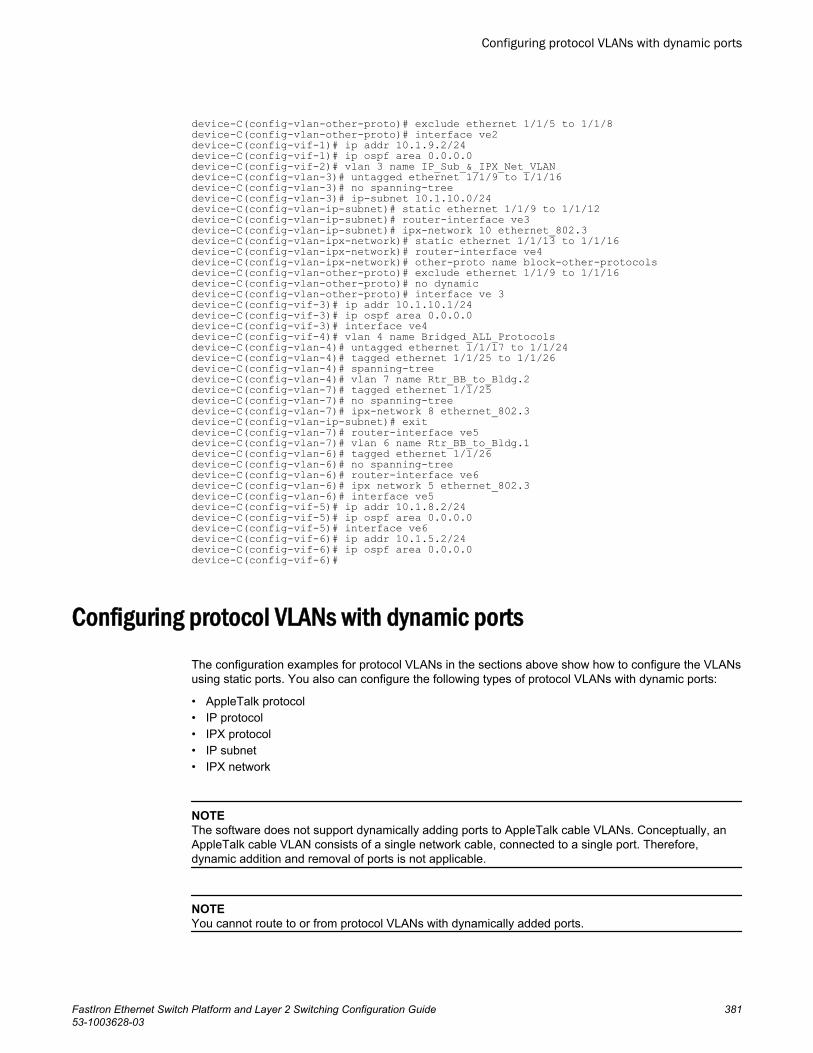
device-C(config-vlan-other-proto)# exclude ethernet 1/1/5 to 1/1/8device-C(config-vlan-other-proto)# interface ve2device-C(config-vif-1)# ip addr 10.1.9.2/24device-C(config-vif-1)# ip ospf area 0.0.0.0device-C(config-vif-2)# vlan 3 name IP_Sub_&_IPX_Net_VLANdevice-C(config-vlan-3)# untagged ethernet 1/1/9 to 1/1/16device-C(config-vlan-3)# no spanning-treedevice-C(config-vlan-3)# ip-subnet 10.1.10.0/24device-C(config-vlan-ip-subnet)# static ethernet 1/1/9 to 1/1/12device-C(config-vlan-ip-subnet)# router-interface ve3device-C(config-vlan-ip-subnet)# ipx-network 10 ethernet_802.3device-C(config-vlan-ipx-network)# static ethernet 1/1/13 to 1/1/16device-C(config-vlan-ipx-network)# router-interface ve4device-C(config-vlan-ipx-network)# other-proto name block-other-protocolsdevice-C(config-vlan-other-proto)# exclude ethernet 1/1/9 to 1/1/16device-C(config-vlan-other-proto)# no dynamicdevice-C(config-vlan-other-proto)# interface ve 3device-C(config-vif-3)# ip addr 10.1.10.1/24device-C(config-vif-3)# ip ospf area 0.0.0.0device-C(config-vif-3)# interface ve4device-C(config-vif-4)# vlan 4 name Bridged_ALL_Protocolsdevice-C(config-vlan-4)# untagged ethernet 1/1/17 to 1/1/24device-C(config-vlan-4)# tagged ethernet 1/1/25 to 1/1/26device-C(config-vlan-4)# spanning-treedevice-C(config-vlan-4)# vlan 7 name Rtr_BB_to_Bldg.2device-C(config-vlan-7)# tagged ethernet 1/1/25device-C(config-vlan-7)# no spanning-treedevice-C(config-vlan-7)# ipx-network 8 ethernet_802.3device-C(config-vlan-ip-subnet)# exitdevice-C(config-vlan-7)# router-interface ve5device-C(config-vlan-7)# vlan 6 name Rtr_BB_to_Bldg.1device-C(config-vlan-6)# tagged ethernet 1/1/26device-C(config-vlan-6)# no spanning-treedevice-C(config-vlan-6)# router-interface ve6device-C(config-vlan-6)# ipx network 5 ethernet_802.3device-C(config-vlan-6)# interface ve5device-C(config-vif-5)# ip addr 10.1.8.2/24device-C(config-vif-5)# ip ospf area 0.0.0.0device-C(config-vif-5)# interface ve6device-C(config-vif-6)# ip addr 10.1.5.2/24device-C(config-vif-6)# ip ospf area 0.0.0.0device-C(config-vif-6)#
Configuring protocol VLANs with dynamic portsThe configuration examples for protocol VLANs in the sections above show how to configure the VLANsusing static ports. You also can configure the following types of protocol VLANs with dynamic ports:
• AppleTalk protocol• IP protocol• IPX protocol• IP subnet• IPX network
NOTEThe software does not support dynamically adding ports to AppleTalk cable VLANs. Conceptually, anAppleTalk cable VLAN consists of a single network cable, connected to a single port. Therefore,dynamic addition and removal of ports is not applicable.
NOTEYou cannot route to or from protocol VLANs with dynamically added ports.
Configuring protocol VLANs with dynamic ports
FastIron Ethernet Switch Platform and Layer 2 Switching Configuration Guide 38153-1003628-03
Aging of dynamic portsWhen you add the ports to the VLAN, the software automatically adds them all to the VLAN. However,dynamically added ports age out. If the age time for a dynamic port expires, the software removes theport from the VLAN. If that port receives traffic for the IP subnet or IPX network, the software adds theport to the VLAN again and starts the aging timer over. Each time the port receives traffic for theVLAN's IP subnet or IPX network, the aging timer starts over.
NOTEYou can disable VLAN membership aging of dynamically added ports. Refer to Disabling membershipaging of dynamic VLAN ports on page 382).
Dynamic ports within any protocol VLAN age out after 10 minutes, if no member protocol traffic isreceived on a port within the VLAN. The aged out port, however, remains as a candidate dynamic portfor that VLAN. The port becomes active in the VLAN again if member protocol traffic is received onthat port.
Once a port is re-activated, the aging out period for the port is reset to 20 minutes. Each time amember protocol packet is received by a candidate dynamic port (aged out port) the port becomesactive again and the aging out period is reset for 20 minutes.
Disabling membership aging of dynamic VLAN ports
You can disable VLAN membership aging of ports that are dynamically assigned to protocol or subnet-based VLANs. This feature resolves the connectivity issue that may occur in certain configurationswhen protocol or subnet VLANs are configured with dynamic port membership.
NOTEThis issue does not occur with statically assigned VLAN memberships. Thus, enable this feature onlyif your configuration includes dynamically assigned VLAN memberships for protocol or subnet VLANs.
To enable this feature, enter commands such as the following.
device(config)# vlan 10 by portdevice(config-vlan-10)# interface ethernet 1/1/1 to 1/1/5 device(config-vlan-10)# ip-proto name IP_Prot_VLANdevice(config-vlan-ip-proto)# no-dynamic-agingdevice(config-vlan-ip-proto)# write memoryThese commands create an IP protocol VLAN and disable the VLAN membership aging of ports thatare dynamically assigned to the protocol VLAN.
Syntax: [no] no-dynamic-aging
Enter the no form of the command to disable this feature after it has been enabled.
By default, VLAN membership of dynamically assigned ports will age out after a period of time if nopackets belonging to that protocol or subnet VLAN are received by the CPU.
The output of the show running-config command indicates if the no-dynamic-aging feature isenabled for a specific protocol or subnet VLAN.
Aging of dynamic ports
382 FastIron Ethernet Switch Platform and Layer 2 Switching Configuration Guide53-1003628-03

Configuration guidelines for membership aging of dynamic VLAN ports• You cannot dynamically add a port to a protocol VLAN if the port has any routing configuration
parameters. For example, the port cannot have a virtual routing interface, IP subnet address, IPXnetwork address, or AppleTalk network address configured on it.
• Once you dynamically add a port to a protocol VLAN, you cannot configure routing parameters onthe port.
• Dynamic VLAN ports are not required or supported on AppleTalk cable VLANs.• When protocol VLANs with dynamic ports are configured, the output of the show running-config
command in the Router image will show the "dynamic" keyword. In the Switch image, the keyword isnot shown in the output of the show running-config command.
NOTEIn the Switch image, all the ports are dynamic ports by-default, so the dynamic command does notappear in the show running-config command output. If you configure the no dynamic command, itwill appear in the output of the show running-config command. Similarly in Router image, no ports aredynamic by-default, so the no dynamic command does not appear in the output of the show running-config command. If you configure the dynamic command, it will appear in the output of the showrunning-config command.
Configuring an IP, IPX, or AppleTalk Protocol VLAN with Dynamic PortsTo configure an IP, IPX, or AppleTalk protocol VLAN with dynamic ports, use the following method.
To configure port-based VLAN 10, then configure an IP protocol VLAN within the port-based VLAN withdynamic ports, enter the following commands such as the following.
device(config)# vlan 10 by portdevice(config-vlan-10)# untagged ethernet 1/1/1 to 1/1/6added untagged port ethe 1/1/1 to 1/1/6 to port-vlan 30.device(config-vlan-10)# ip-proto name IP_Prot_VLANdevice(config-vlan-ip-proto)# dynamicdevice(config)# write memorySyntax: vlan vlan-id name string [ by port ]
Syntax: untagged ethernet unit/slotnum/portnum to unit/slotnum/portnum
or
Syntax: untagged ethernet unit/slotnum/portnum ethernet unit/slotnum/portnum
NOTEUse the first untagged command for adding a range of ports. Use the second command for addingseparate ports (not in a range).
Syntax: ip-proto [ name string]
Syntax: ipx-proto [ name string]
Syntax: appletalk-cable-vlan num [ name string]
Syntax: dynamic
The procedure is similar for IPX and AppleTalk protocol VLANs. Enter ipx-proto or atalk-proto insteadof ip-proto .
Configuration guidelines for membership aging of dynamic VLAN ports
FastIron Ethernet Switch Platform and Layer 2 Switching Configuration Guide 38353-1003628-03
Configuring an IP subnet VLAN with dynamic portsTo configure port-based VLAN 10, then configure an IP subnet VLAN within the port-based VLAN withdynamic ports, enter commands such as the following.
device(config)# vlan 10 name IP_VLAN by port device(config-vlan-10)# untagged ethernet 1/1/1 to 1/1/6added untagged port ethe 1/1/1 to 1/1/6 to port-vlan 10. device(config-vlan-10)# ip-subnet 10.1.1.0/24 name Mktg-LANdevice(config-vlan-ip-subnet)# dynamic device(config)# write memoryThese commands create a port-based VLAN on chassis ports 1/1/1 - 1/1/6 named "Mktg-LAN",configure an IP subnet VLAN within the port-based VLAN, and then add ports from the port-basedVLAN dynamically.
Syntax: vlan vlan-id name string [ by port ]
Syntax: untagged ethernet unit/slotnum/portnum to unit/slotnum/portnum
or
Syntax: untagged ethernet unit/slotnum/portnum ethernet unit/slotnum/portnum
NOTEUse the first untagged command for adding a range of ports. Use the second command for addingseparate ports (not in a range).
Syntax: ip-subnet ip-addr ip-mask[ name string]
or
Syntax: ip-subnet ip-addr/mask-bits [ name string]
Syntax: dynamic
Configuring an IPX network VLAN with dynamic portsTo configure port-based VLAN 20, then configure an IPX network VLAN within the port-based VLANwith dynamic ports, enter commands such as the following.
device(config)# vlan 20 name IPX_VLAN by port device(config-vlan-10)# untagged ethernet 1/2/1 to 1/2/6added untagged port ethe 1/2/1 to 1/2/6 to port-vlan 20. device(config-vlan-10)# ipx-network abcd ethernet_ii name Eng-LANdevice(config-vlan-ipx-network)# dynamicdevice(config)# write memoryThese commands create a port-based VLAN on chassis ports 1/2/1 - 1/2/6 named "Eng-LAN",configure an IPX network VLAN within the port-based VLAN, and then add ports from the port-basedVLAN dynamically.
Syntax: vlan vlan-id name string [ by port ]
Syntax: untagged ethernet unit/slotnum/portnum to unit/slotnum/portnum
or
Syntax: untagged ethernet unit/slotnum/portnum ethernet unit/slotnum/portnum
Configuring an IP subnet VLAN with dynamic ports
384 FastIron Ethernet Switch Platform and Layer 2 Switching Configuration Guide53-1003628-03
NOTEUse the first untagged command for adding a range of ports. Use the second command for addingseparate ports (not in a range).
Syntax: ipx-network network-addr ethernet_ii|ethernet_802.2 | ethernet_802.3 | ethernet_snap[name string]
Syntax: dynamic
Configuring uplink ports within a port-based VLANYou can configure a subset of the ports in a port-based VLAN as uplink ports. When you configureuplink ports in a port-based VLAN, the device sends all broadcast and unknown-unicast traffic from aport in the VLAN to the uplink ports, but not to other ports within the VLAN. Thus, the uplink portsprovide tighter broadcast control within the VLAN.
This uplink port feature behaves the same as the private VLAN (PVLAN) feature, but with the ability tosupport tagged ports. This feature also supports two PVLAN modes: the Primary ports (uplink ports)and Isolated ports (host ports).
For example, if two ports within a port-based VLAN are Gbps ports attached to the network and theother ports are 1/10/100 ports attached to clients, you can configure the two ports attached to thenetwork as uplink ports. In this configuration, broadcast and unknown-unicast traffic in the VLAN doesnot go to all ports. The traffic goes only to the uplink ports. The clients on the network do not receivebroadcast and unknown-unicast traffic from other ports, including other clients.
Configuration considerations for uplink ports within a port-based VLAN• When this feature is enabled, flooded traffic (unknown unicast, unregistered multicast, and broadcast
traffic) is software forwarded. ACL-based rate limit is non-functional with uplink switch configuration.• This feature should not be enabled with protocol VLANs or PVLANs in the same VLAN.• CPU spike is expected when this feature is enabled.
Configuration syntax for uplink ports within a port-based VLANTo configure a port-based VLAN containing uplink ports, enter commands such as the following.
Device(config)# vlan 10 by portDevice(config-vlan-10)# untagged ethernet 1/1/1 to 1/1/24Device(config-vlan-10)# untagged ethernet 1/2/1 to 1/2/2Device(config-vlan-10)# uplink-switch ethernet 1/2/1 to 1/2/2Syntax: [no] uplink-switch ethernet unit/slotnum/portnum [ to unit/slotnum/portnum | ethernet unit/slotnum/portnum ]
In this example, 24 ports on a 1/10/100 module and two Gbps ports on a Gbps module are added toport-based VLAN 10. The two Gbps ports are then configured as uplink ports.
NOTEThis feature is not supported on the Brocade ICX 7750, Brocade ICX 7450, or Brocade ICX 7250.
Configuring uplink ports within a port-based VLAN
FastIron Ethernet Switch Platform and Layer 2 Switching Configuration Guide 38553-1003628-03
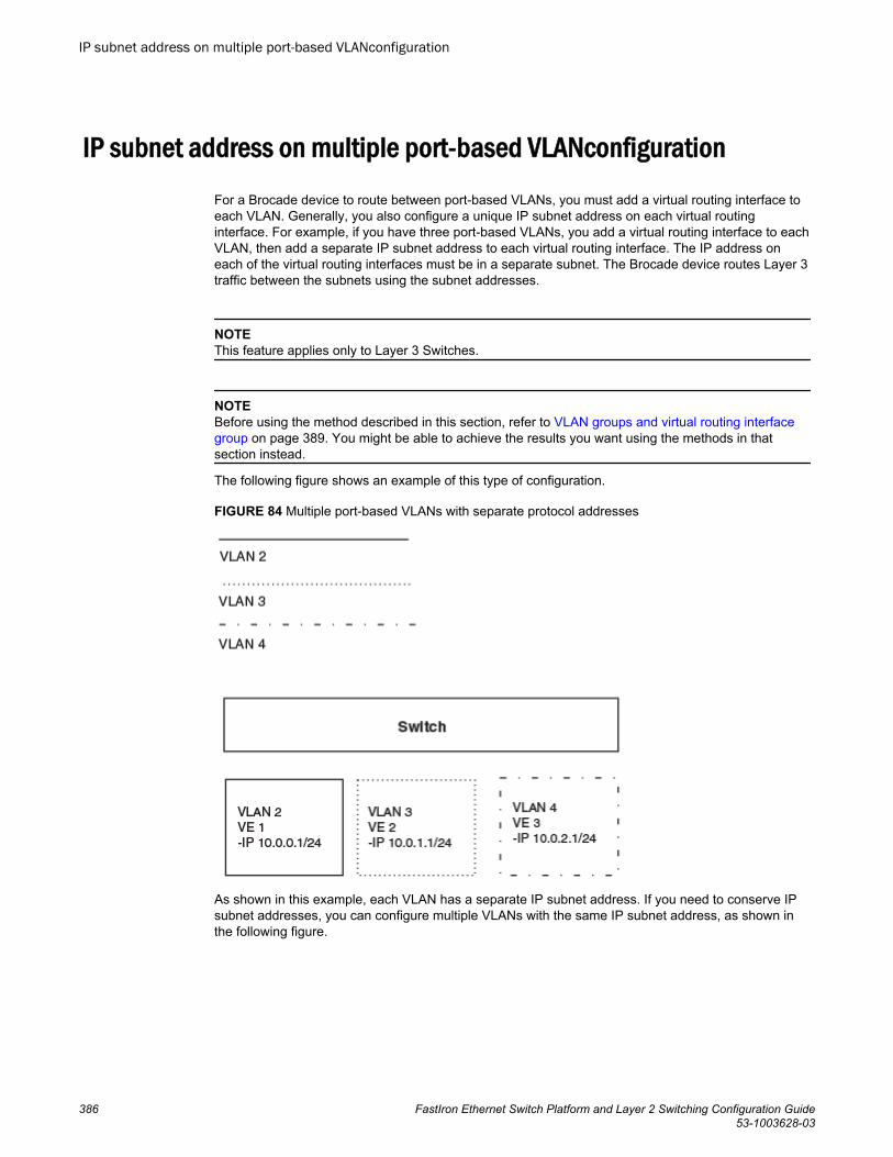
IP subnet address on multiple port-based VLANconfiguration
For a Brocade device to route between port-based VLANs, you must add a virtual routing interface toeach VLAN. Generally, you also configure a unique IP subnet address on each virtual routinginterface. For example, if you have three port-based VLANs, you add a virtual routing interface to eachVLAN, then add a separate IP subnet address to each virtual routing interface. The IP address oneach of the virtual routing interfaces must be in a separate subnet. The Brocade device routes Layer 3traffic between the subnets using the subnet addresses.
NOTEThis feature applies only to Layer 3 Switches.
NOTEBefore using the method described in this section, refer to VLAN groups and virtual routing interfacegroup on page 389. You might be able to achieve the results you want using the methods in thatsection instead.
The following figure shows an example of this type of configuration.
FIGURE 84 Multiple port-based VLANs with separate protocol addresses
As shown in this example, each VLAN has a separate IP subnet address. If you need to conserve IPsubnet addresses, you can configure multiple VLANs with the same IP subnet address, as shown inthe following figure.
IP subnet address on multiple port-based VLANconfiguration
386 FastIron Ethernet Switch Platform and Layer 2 Switching Configuration Guide53-1003628-03
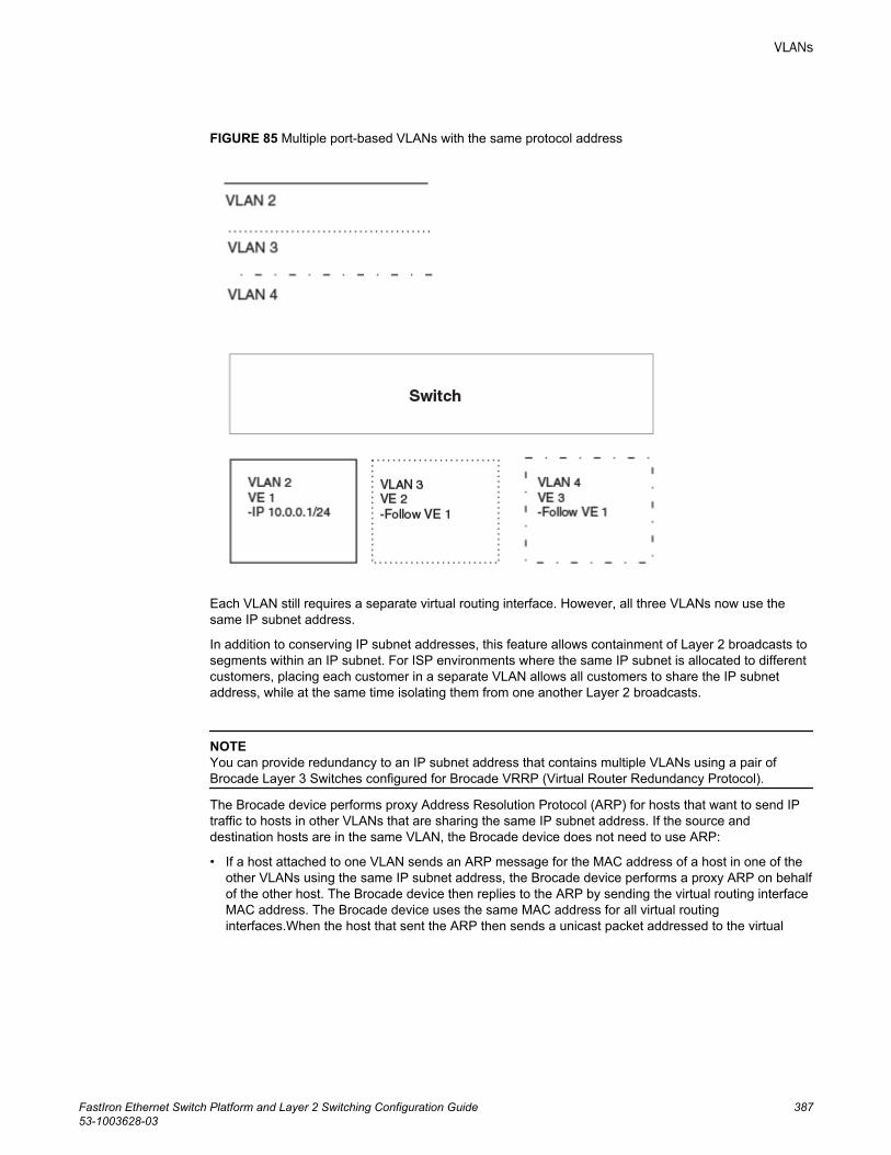
FIGURE 85 Multiple port-based VLANs with the same protocol address
Each VLAN still requires a separate virtual routing interface. However, all three VLANs now use thesame IP subnet address.
In addition to conserving IP subnet addresses, this feature allows containment of Layer 2 broadcasts tosegments within an IP subnet. For ISP environments where the same IP subnet is allocated to differentcustomers, placing each customer in a separate VLAN allows all customers to share the IP subnetaddress, while at the same time isolating them from one another Layer 2 broadcasts.
NOTEYou can provide redundancy to an IP subnet address that contains multiple VLANs using a pair ofBrocade Layer 3 Switches configured for Brocade VRRP (Virtual Router Redundancy Protocol).
The Brocade device performs proxy Address Resolution Protocol (ARP) for hosts that want to send IPtraffic to hosts in other VLANs that are sharing the same IP subnet address. If the source anddestination hosts are in the same VLAN, the Brocade device does not need to use ARP:
• If a host attached to one VLAN sends an ARP message for the MAC address of a host in one of theother VLANs using the same IP subnet address, the Brocade device performs a proxy ARP on behalfof the other host. The Brocade device then replies to the ARP by sending the virtual routing interfaceMAC address. The Brocade device uses the same MAC address for all virtual routinginterfaces.When the host that sent the ARP then sends a unicast packet addressed to the virtual
VLANs
FastIron Ethernet Switch Platform and Layer 2 Switching Configuration Guide 38753-1003628-03
routing interface MAC address, the device switches the packet on Layer 3 to the destination host onthe VLAN.
NOTEIf the Brocade device ARP table does not contain the requested host, the Brocade device forwards theARP request on Layer 2 to the same VLAN as the one that received the ARP request. Then the devicesends an ARP for the destination to the other VLANs that are using the same IP subnet address.
• If the destination is in the same VLAN as the source, the Brocade device does not need to performa proxy ARP.
To configure multiple VLANs to use the same IP subnet address:
• Configure each VLAN, including adding tagged or untagged ports.• Configure a separate virtual routing interface for each VLAN, but do not add an IP subnet address
to more than one of the virtual routing interfaces.• Configure the virtual routing interfaces that do not have the IP subnet address to "follow" the virtual
routing interface that does have the address.
To configure the VLANs shown in Figure 85 , you could enter the following commands.
device(config)# vlan 1 by portdevice(config-vlan-1)# untagged ethernet 1/1/1device(config-vlan-1)# tagged ethernet 1/1/8device(config-vlan-1)# router-interface ve 1Syntax: router-interface ve number
The commands above configure port-based VLAN 1. The VLAN has one untagged port (1/1/1) and atagged port (1/1/8). In this example, all three VLANs contain port 1/1/8 so the port must be tagged toallow the port to be in multiple VLANs. You can configure VLANs to share a Layer 3 protocol interfaceregardless of tagging. A combination of tagged and untagged ports is shown in this example todemonstrate that sharing the interface does not change other VLAN features.
Notice that each VLAN still requires a unique virtual routing interface.
The following commands configure port-based VLANs 2 and 3.
device(config-vlan-1)# vlan 2 by portdevice(config-vlan-2)# untagged ethernet 1/1/2device(config-vlan-2)# tagged ethernet 1/1/8device(config-vlan-2)# router-interface ve 2device(config-vlan-2)# vlan 3 by portdevice(config-vlan-3)# untagged ethernet 1/1/5 to 1/1/6device(config-vlan-3)# tagged ethernet 1/1/8device(config-vlan-3)# router-interface ve 3The following commands configure an IP subnet address on virtual routing interface 1.
device(config-vlan-3)# interface ve 1device(config-vif-1)# ip address 10.0.0.1/24The following commands configure virtual routing interfaces 2 and 3 to "follow" the IP subnet addressconfigured on virtual routing interface 1.
device(config-vif-1)# interface ve 2device(config-vif-2)# ip follow ve 1device(config-vif-2)# interface ve 3device(config-vif-3)# ip follow ve 1
VLANs
388 FastIron Ethernet Switch Platform and Layer 2 Switching Configuration Guide53-1003628-03
NOTEBecause virtual routing interfaces 2 and 3 do not have their own IP subnet addresses but instead are"following" virtual routing interface a IP address, you still can configure an IPX or AppleTalk interface onvirtual routing interfaces 2 and 3.
VLAN groups and virtual routing interface groupTo simplify configuration when you have many VLANs with the same configuration, you can configureVLAN groups and virtual routing interface groups.
NOTEVLAN groups are supported on Layer 3 Switches and Layer 2 Switches. Virtual routing interface groupsare supported only on Layer 3 Switches.
When you create a VLAN group, the VLAN parameters you configure for the group apply to all theVLANs within the group. Additionally, you can easily associate the same IP subnet interface with all theVLANs in a group by configuring a virtual routing interface group with the same ID as the VLAN group.
• The VLAN group feature allows you to create multiple port-based VLANs with identical portmembers. Because the member ports are shared by all the VLANs within the group, you must addthe ports as tagged ports. This feature not only simplifies VLAN configuration but also allows you tohave a large number of identically configured VLANs in a startup-config file on the device flashmemory module. Normally, a startup-config file with a large number of VLANs might not fit on theflash memory module. By grouping the identically configured VLANs, you can conserve space in thestartup-config file so that it fits on the flash memory module.
• The virtual routing interface group feature is useful when you want to configure the same IP subnetaddress on all the port-based VLANs within a VLAN group. You can configure a virtual routinginterface group only after you configure a VLAN group with the same ID. The virtual routing interfacegroup automatically applies to the VLANs in the VLAN group that has the same ID and cannot beapplied to other VLAN groups or to individual VLANs.
You can create up to 32 VLAN groups and 32 virtual routing interface groups. A virtual routing interfacegroup always applies only to the VLANs in the VLAN group with the same ID.
NOTEDepending on the size of the VLAN ID range you want to use for the VLAN group, you might need toallocate additional memory for VLANs. On Layer 3 Switches, if you allocate additional memory forVLANs, you also need to allocate the same amount of memory for virtual routing interfaces. This is trueregardless of whether you use the virtual routing interface groups. To allocate additional memory, referto Allocating memory for more VLANs or virtual routing interfaces on page 393.
VLAN groups and virtual routing interface group
FastIron Ethernet Switch Platform and Layer 2 Switching Configuration Guide 38953-1003628-03
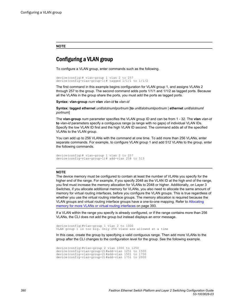
NOTE
Configuring a VLAN groupTo configure a VLAN group, enter commands such as the following.
device(config)# vlan-group 1 vlan 2 to 257device(config-vlan-group-1)# tagged 1/1/1 to 1/1/2The first command in this example begins configuration for VLAN group 1, and assigns VLANs 2through 257 to the group. The second command adds ports 1/1/1 and 1/1/2 as tagged ports. Becauseall the VLANs in the group share the ports, you must add the ports as tagged ports.
Syntax: vlan-group num vlan vlan-id to vlan-id
Syntax: tagged ethernet unit/slotnum/portnum [to unit/slotnum/portnum | ethernet unit/slotnum/portnum]
The vlan-group num parameter specifies the VLAN group ID and can be from 1 - 32. The vlan vlan-idto vlan-id parameters specify a contiguous range (a range with no gaps) of individual VLAN IDs.Specify the low VLAN ID first and the high VLAN ID second. The command adds all of the specifiedVLANs to the VLAN group.
You can add up to 256 VLANs with the command at one time. To add more than 256 VLANs, enterseparate commands. For example, to configure VLAN group 1 and add 512 VLANs to the group, enterthe following commands.
device(config)# vlan-group 1 vlan 2 to 257 device(config-vlan-group-1)# add-vlan 258 to 513
NOTEThe device memory must be configured to contain at least the number of VLANs you specify for thehigher end of the range. For example, if you specify 2048 as the VLAN ID at the high end of the range,you first must increase the memory allocation for VLANs to 2048 or higher. Additionally, on Layer 3Switches, if you allocate additional memory for VLANs, you also need to allocate the same amount ofmemory for virtual routing interfaces, before you configure the VLAN groups. This is true regardless ofwhether you use the virtual routing interface groups. The memory allocation is required because theVLAN groups and virtual routing interface groups have a one-to-one mapping. Refer to Allocatingmemory for more VLANs or virtual routing interfaces on page 393.
If a VLAN within the range you specify is already configured, or if the range contains more than 256VLANs, the CLI does not add the group but instead displays an error message.
device(config)#vlan-group 1 vlan 2 to 1000 VLAN group 1 is too big. Only 256 vlans are allowed at a timeIn this case, create the group by specifying a valid contiguous range. Then add more VLANs to thegroup after the CLI changes to the configuration level for the group. See the following example.
device(config)#vlan-group 2 vlan 1000 to 1250device(config-vlan-group-2)#add-vlan 1251 to 1500device(config-vlan-group-2)#add-vlan 1501 to 1750device(config-vlan-group-2)#add-vlan 1751 to 2000
Configuring a VLAN group
390 FastIron Ethernet Switch Platform and Layer 2 Switching Configuration Guide53-1003628-03
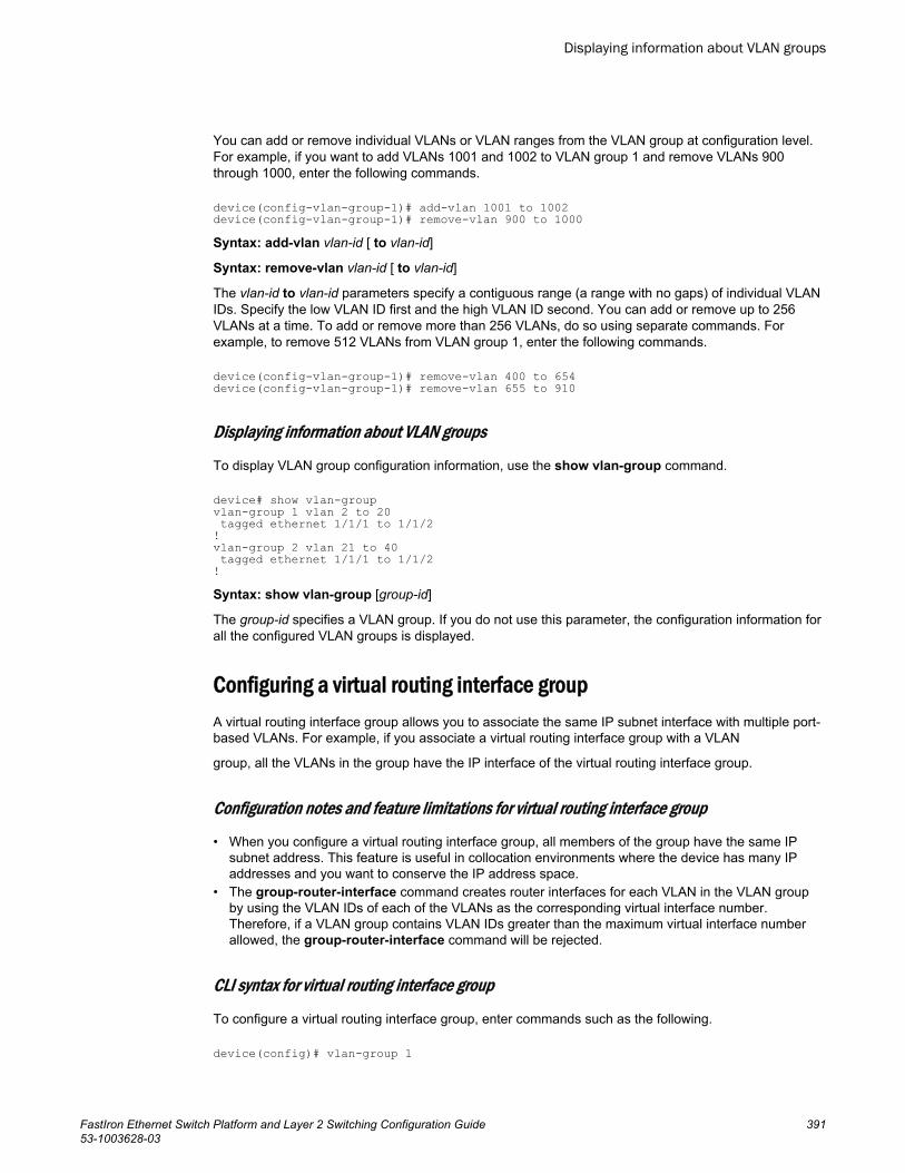
You can add or remove individual VLANs or VLAN ranges from the VLAN group at configuration level.For example, if you want to add VLANs 1001 and 1002 to VLAN group 1 and remove VLANs 900through 1000, enter the following commands.
device(config-vlan-group-1)# add-vlan 1001 to 1002device(config-vlan-group-1)# remove-vlan 900 to 1000Syntax: add-vlan vlan-id [ to vlan-id]
Syntax: remove-vlan vlan-id [ to vlan-id]
The vlan-id to vlan-id parameters specify a contiguous range (a range with no gaps) of individual VLANIDs. Specify the low VLAN ID first and the high VLAN ID second. You can add or remove up to 256VLANs at a time. To add or remove more than 256 VLANs, do so using separate commands. Forexample, to remove 512 VLANs from VLAN group 1, enter the following commands.
device(config-vlan-group-1)# remove-vlan 400 to 654device(config-vlan-group-1)# remove-vlan 655 to 910
Displaying information about VLAN groups
To display VLAN group configuration information, use the show vlan-group command.
device# show vlan-groupvlan-group 1 vlan 2 to 20 tagged ethernet 1/1/1 to 1/1/2 !vlan-group 2 vlan 21 to 40 tagged ethernet 1/1/1 to 1/1/2 !Syntax: show vlan-group [group-id]
The group-id specifies a VLAN group. If you do not use this parameter, the configuration information forall the configured VLAN groups is displayed.
Configuring a virtual routing interface groupA virtual routing interface group allows you to associate the same IP subnet interface with multiple port-based VLANs. For example, if you associate a virtual routing interface group with a VLAN
group, all the VLANs in the group have the IP interface of the virtual routing interface group.
Configuration notes and feature limitations for virtual routing interface group
• When you configure a virtual routing interface group, all members of the group have the same IPsubnet address. This feature is useful in collocation environments where the device has many IPaddresses and you want to conserve the IP address space.
• The group-router-interface command creates router interfaces for each VLAN in the VLAN groupby using the VLAN IDs of each of the VLANs as the corresponding virtual interface number.Therefore, if a VLAN group contains VLAN IDs greater than the maximum virtual interface numberallowed, the group-router-interface command will be rejected.
CLI syntax for virtual routing interface group
To configure a virtual routing interface group, enter commands such as the following.
device(config)# vlan-group 1
Displaying information about VLAN groups
FastIron Ethernet Switch Platform and Layer 2 Switching Configuration Guide 39153-1003628-03

device(config-vlan-group-1)# group-router-interfacedevice(config-vlan-group-1)# exitdevice(config)# interface group-ve 1device(config-vif-group-1)# ip address 10.10.10.1/24These commands enable VLAN group 1 to have a group virtual routing interface, then configure virtualrouting interface group 1. The software always associates a virtual routing interface group only withthe VLAN group that has the same ID. In this example, the VLAN group ID is 1, so the correspondingvirtual routing interface group also must have ID 1.
Syntax: group-router-interface
Syntax: interface group-ve num
Syntax: [no] ip address ip-addr ip-mask [ secondary ]
or
Syntax: [no] ip address ip-addr/mask-bits [ secondary ]
The router-interface-group command enables a VLAN group to use a virtual routing interface group.Enter this command at the configuration level for the VLAN group. This command configures theVLAN group to use the virtual routing interface group that has the same ID as the VLAN group. Youcan enter this command when you configure the VLAN group for the first time or later, after you haveadded tagged ports to the VLAN and so on.
The num parameter in the interface group-venum command specifies the ID of the VLAN group withwhich you want to associate this virtual routing interface group. The VLAN group must already beconfigured and enabled to use a virtual routing interface group. The software automatically associatesthe virtual routing interface group with the VLAN group that has the same ID. You can associate avirtual routing interface group only with the VLAN group that has the same ID.
NOTEIPv6 is not supported with group-ve .
NOTEFCX devices do not support ACLs with group-ve .
NOTEFastIron devices support group-ve with OSPF, VRRP v2 and VRRP-E v2 protocols only.
The syntax and usage for the ip address command is the same as when you use the command at theinterface level to add an IP interface.
Displaying the VLAN group and virtual routing interface groupinformationTo verify configuration of VLAN groups and virtual routing interface groups, display the running-configfile. If you have saved the configuration to the startup-config file, you also can verify the configurationby displaying the startup-config file. The following example shows the running-config information forthe VLAN group and virtual routing interface group configured in the previous examples. Theinformation appears in the same way in the startup-config file.
device# show running-configlines not related to the VLAN group omitted...vlan-group 1 vlan 2 to 20
Displaying the VLAN group and virtual routing interface group information
392 FastIron Ethernet Switch Platform and Layer 2 Switching Configuration Guide53-1003628-03
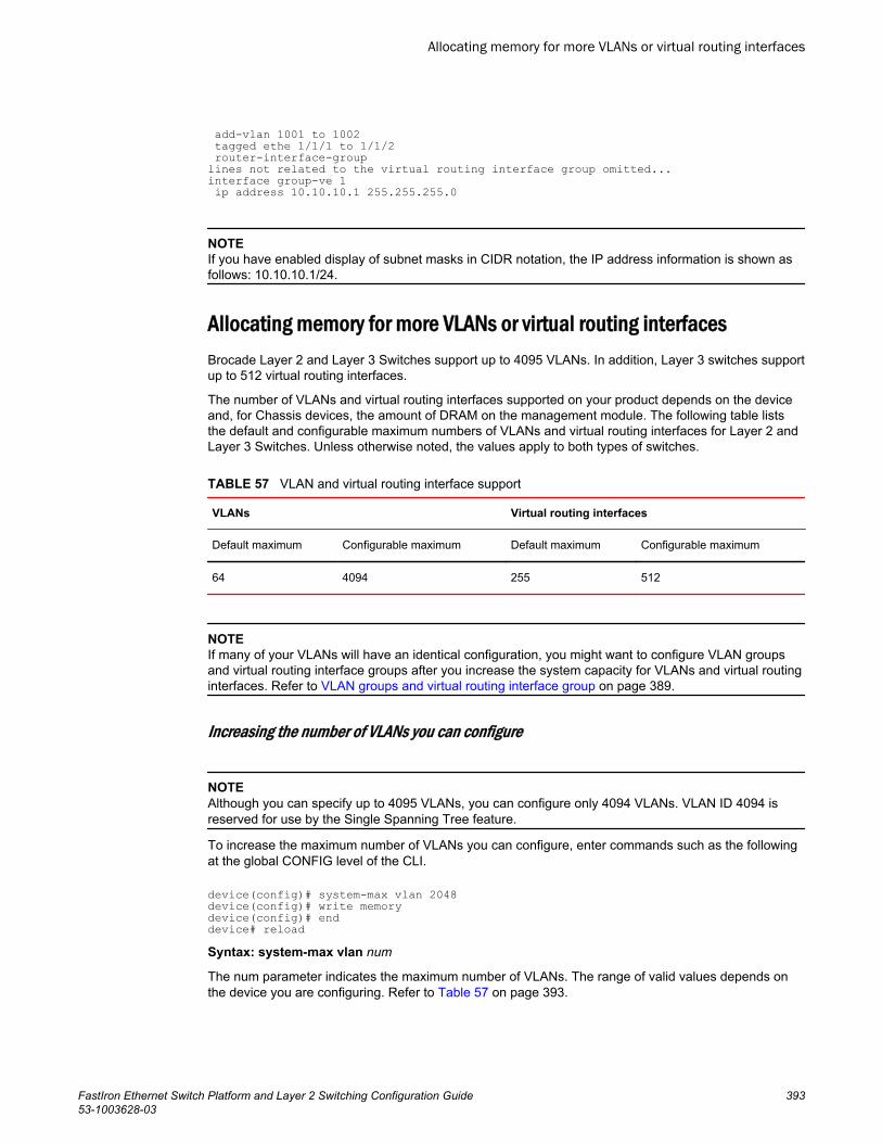
add-vlan 1001 to 1002 tagged ethe 1/1/1 to 1/1/2 router-interface-grouplines not related to the virtual routing interface group omitted...interface group-ve 1 ip address 10.10.10.1 255.255.255.0
NOTEIf you have enabled display of subnet masks in CIDR notation, the IP address information is shown asfollows: 10.10.10.1/24.
Allocating memory for more VLANs or virtual routing interfacesBrocade Layer 2 and Layer 3 Switches support up to 4095 VLANs. In addition, Layer 3 switches supportup to 512 virtual routing interfaces.
The number of VLANs and virtual routing interfaces supported on your product depends on the deviceand, for Chassis devices, the amount of DRAM on the management module. The following table liststhe default and configurable maximum numbers of VLANs and virtual routing interfaces for Layer 2 andLayer 3 Switches. Unless otherwise noted, the values apply to both types of switches.
VLAN and virtual routing interface support TABLE 57
VLANs Virtual routing interfaces
Default maximum Configurable maximum Default maximum Configurable maximum
64 4094 255 512
NOTEIf many of your VLANs will have an identical configuration, you might want to configure VLAN groupsand virtual routing interface groups after you increase the system capacity for VLANs and virtual routinginterfaces. Refer to VLAN groups and virtual routing interface group on page 389.
Increasing the number of VLANs you can configure
NOTEAlthough you can specify up to 4095 VLANs, you can configure only 4094 VLANs. VLAN ID 4094 isreserved for use by the Single Spanning Tree feature.
To increase the maximum number of VLANs you can configure, enter commands such as the followingat the global CONFIG level of the CLI.
device(config)# system-max vlan 2048device(config)# write memorydevice(config)# enddevice# reloadSyntax: system-max vlan num
The num parameter indicates the maximum number of VLANs. The range of valid values depends onthe device you are configuring. Refer to Table 57 on page 393.
Allocating memory for more VLANs or virtual routing interfaces
FastIron Ethernet Switch Platform and Layer 2 Switching Configuration Guide 39353-1003628-03
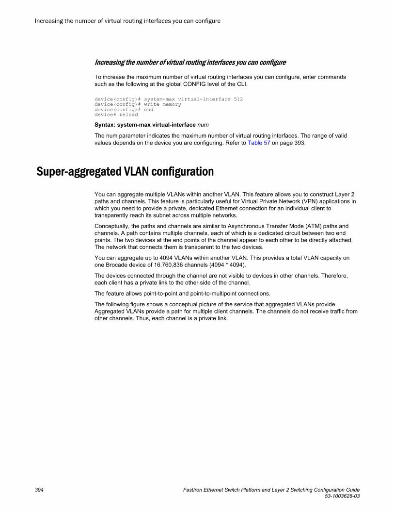
Increasing the number of virtual routing interfaces you can configure
To increase the maximum number of virtual routing interfaces you can configure, enter commandssuch as the following at the global CONFIG level of the CLI.
device(config)# system-max virtual-interface 512device(config)# write memorydevice(config)# enddevice# reloadSyntax: system-max virtual-interface num
The num parameter indicates the maximum number of virtual routing interfaces. The range of validvalues depends on the device you are configuring. Refer to Table 57 on page 393.
Super-aggregated VLAN configurationYou can aggregate multiple VLANs within another VLAN. This feature allows you to construct Layer 2paths and channels. This feature is particularly useful for Virtual Private Network (VPN) applications inwhich you need to provide a private, dedicated Ethernet connection for an individual client totransparently reach its subnet across multiple networks.
Conceptually, the paths and channels are similar to Asynchronous Transfer Mode (ATM) paths andchannels. A path contains multiple channels, each of which is a dedicated circuit between two endpoints. The two devices at the end points of the channel appear to each other to be directly attached.The network that connects them is transparent to the two devices.
You can aggregate up to 4094 VLANs within another VLAN. This provides a total VLAN capacity onone Brocade device of 16,760,836 channels (4094 * 4094).
The devices connected through the channel are not visible to devices in other channels. Therefore,each client has a private link to the other side of the channel.
The feature allows point-to-point and point-to-multipoint connections.
The following figure shows a conceptual picture of the service that aggregated VLANs provide.Aggregated VLANs provide a path for multiple client channels. The channels do not receive traffic fromother channels. Thus, each channel is a private link.
Increasing the number of virtual routing interfaces you can configure
394 FastIron Ethernet Switch Platform and Layer 2 Switching Configuration Guide53-1003628-03
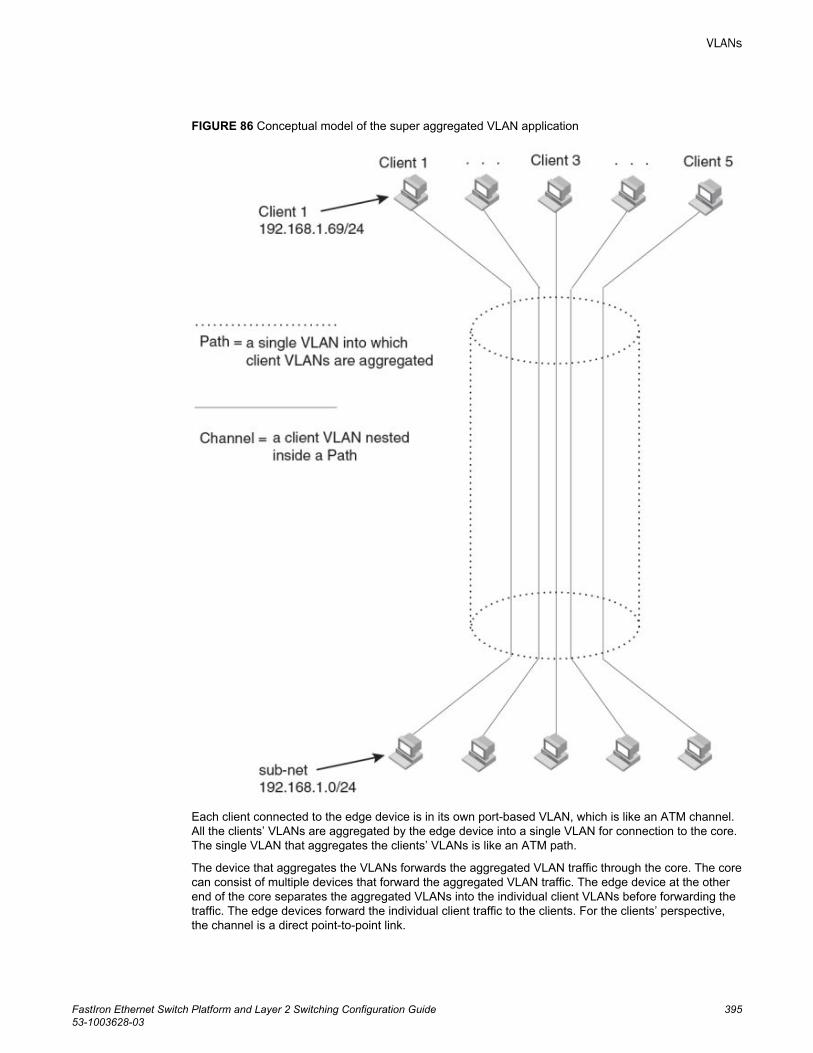
FIGURE 86 Conceptual model of the super aggregated VLAN application
Each client connected to the edge device is in its own port-based VLAN, which is like an ATM channel.All the clients’ VLANs are aggregated by the edge device into a single VLAN for connection to the core.The single VLAN that aggregates the clients’ VLANs is like an ATM path.
The device that aggregates the VLANs forwards the aggregated VLAN traffic through the core. The corecan consist of multiple devices that forward the aggregated VLAN traffic. The edge device at the otherend of the core separates the aggregated VLANs into the individual client VLANs before forwarding thetraffic. The edge devices forward the individual client traffic to the clients. For the clients’ perspective,the channel is a direct point-to-point link.
VLANs
FastIron Ethernet Switch Platform and Layer 2 Switching Configuration Guide 39553-1003628-03
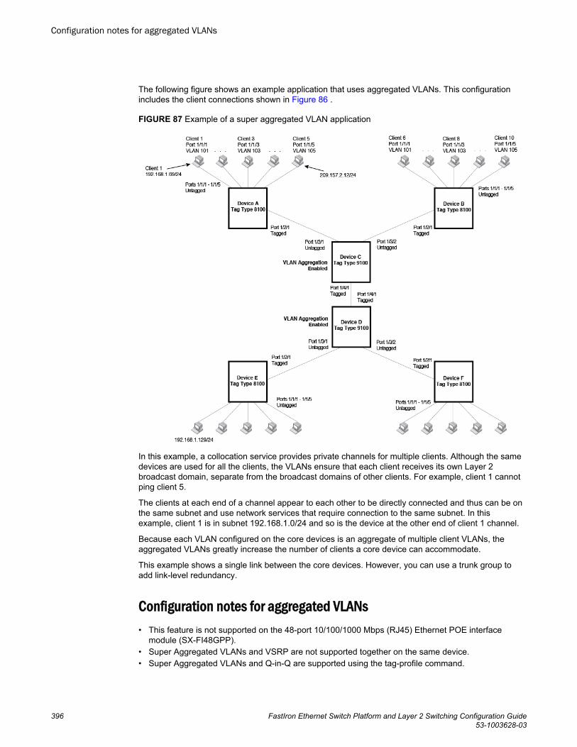
The following figure shows an example application that uses aggregated VLANs. This configurationincludes the client connections shown in Figure 86 .
FIGURE 87 Example of a super aggregated VLAN application
In this example, a collocation service provides private channels for multiple clients. Although the samedevices are used for all the clients, the VLANs ensure that each client receives its own Layer 2broadcast domain, separate from the broadcast domains of other clients. For example, client 1 cannotping client 5.
The clients at each end of a channel appear to each other to be directly connected and thus can be onthe same subnet and use network services that require connection to the same subnet. In thisexample, client 1 is in subnet 192.168.1.0/24 and so is the device at the other end of client 1 channel.
Because each VLAN configured on the core devices is an aggregate of multiple client VLANs, theaggregated VLANs greatly increase the number of clients a core device can accommodate.
This example shows a single link between the core devices. However, you can use a trunk group toadd link-level redundancy.
Configuration notes for aggregated VLANs• This feature is not supported on the 48-port 10/100/1000 Mbps (RJ45) Ethernet POE interface
module (SX-FI48GPP).• Super Aggregated VLANs and VSRP are not supported together on the same device.• Super Aggregated VLANs and Q-in-Q are supported using the tag-profile command.
Configuration notes for aggregated VLANs
396 FastIron Ethernet Switch Platform and Layer 2 Switching Configuration Guide53-1003628-03
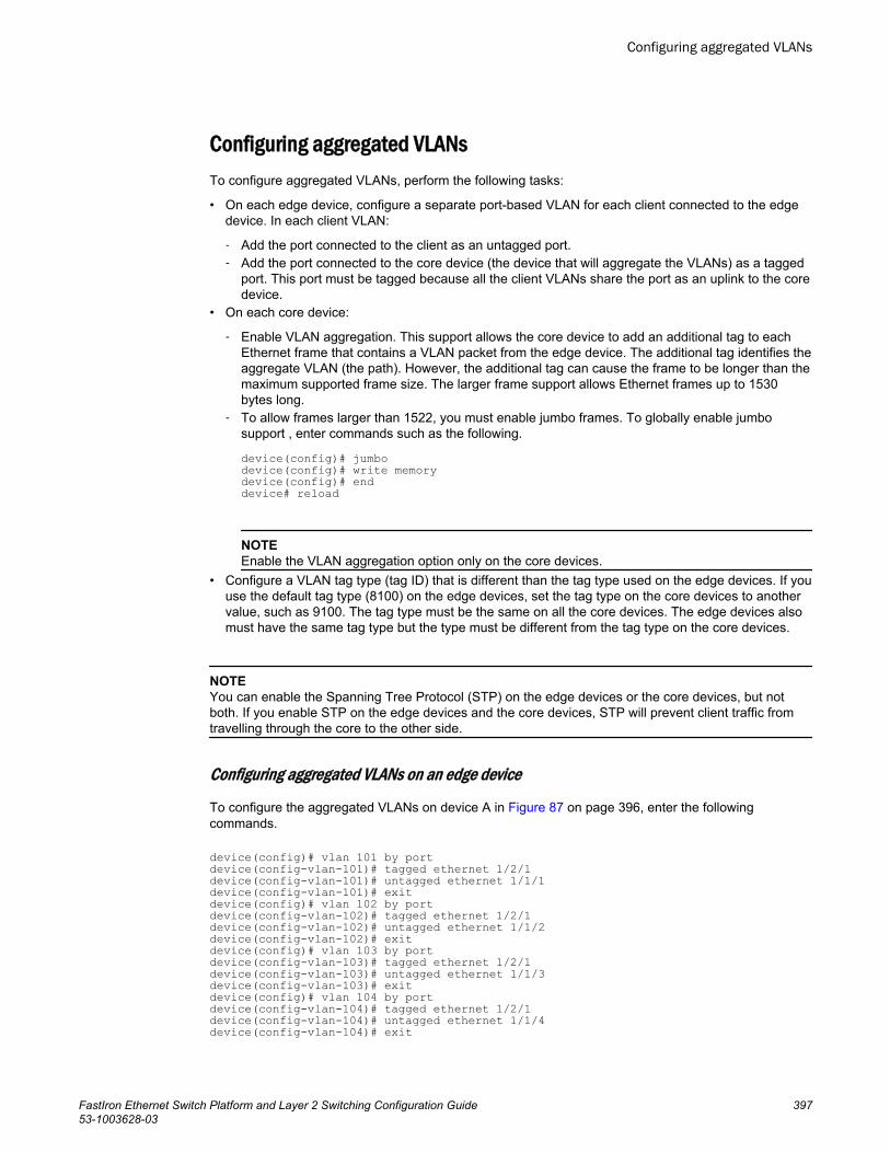
Configuring aggregated VLANsTo configure aggregated VLANs, perform the following tasks:
• On each edge device, configure a separate port-based VLAN for each client connected to the edgedevice. In each client VLAN:
‐ Add the port connected to the client as an untagged port.‐ Add the port connected to the core device (the device that will aggregate the VLANs) as a tagged
port. This port must be tagged because all the client VLANs share the port as an uplink to the coredevice.
• On each core device:
‐ Enable VLAN aggregation. This support allows the core device to add an additional tag to eachEthernet frame that contains a VLAN packet from the edge device. The additional tag identifies theaggregate VLAN (the path). However, the additional tag can cause the frame to be longer than themaximum supported frame size. The larger frame support allows Ethernet frames up to 1530bytes long.
‐ To allow frames larger than 1522, you must enable jumbo frames. To globally enable jumbosupport , enter commands such as the following.
device(config)# jumbodevice(config)# write memorydevice(config)# enddevice# reload
NOTEEnable the VLAN aggregation option only on the core devices.
• Configure a VLAN tag type (tag ID) that is different than the tag type used on the edge devices. If youuse the default tag type (8100) on the edge devices, set the tag type on the core devices to anothervalue, such as 9100. The tag type must be the same on all the core devices. The edge devices alsomust have the same tag type but the type must be different from the tag type on the core devices.
NOTEYou can enable the Spanning Tree Protocol (STP) on the edge devices or the core devices, but notboth. If you enable STP on the edge devices and the core devices, STP will prevent client traffic fromtravelling through the core to the other side.
Configuring aggregated VLANs on an edge device
To configure the aggregated VLANs on device A in Figure 87 on page 396, enter the followingcommands.
device(config)# vlan 101 by portdevice(config-vlan-101)# tagged ethernet 1/2/1device(config-vlan-101)# untagged ethernet 1/1/1device(config-vlan-101)# exitdevice(config)# vlan 102 by portdevice(config-vlan-102)# tagged ethernet 1/2/1device(config-vlan-102)# untagged ethernet 1/1/2device(config-vlan-102)# exitdevice(config)# vlan 103 by portdevice(config-vlan-103)# tagged ethernet 1/2/1device(config-vlan-103)# untagged ethernet 1/1/3device(config-vlan-103)# exitdevice(config)# vlan 104 by portdevice(config-vlan-104)# tagged ethernet 1/2/1device(config-vlan-104)# untagged ethernet 1/1/4device(config-vlan-104)# exit
Configuring aggregated VLANs
FastIron Ethernet Switch Platform and Layer 2 Switching Configuration Guide 39753-1003628-03
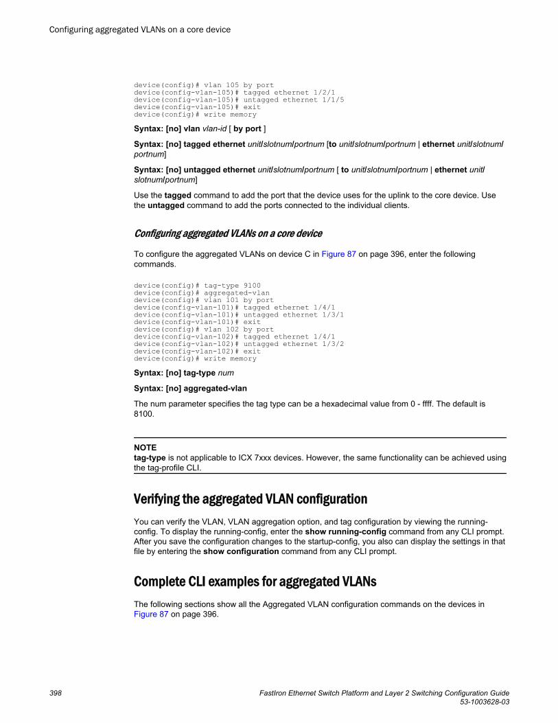
device(config)# vlan 105 by portdevice(config-vlan-105)# tagged ethernet 1/2/1device(config-vlan-105)# untagged ethernet 1/1/5device(config-vlan-105)# exitdevice(config)# write memorySyntax: [no] vlan vlan-id [ by port ]
Syntax: [no] tagged ethernet unit/slotnum/portnum [to unit/slotnum/portnum | ethernet unit/slotnum/portnum]
Syntax: [no] untagged ethernet unit/slotnum/portnum [ to unit/slotnum/portnum | ethernet unit/slotnum/portnum]
Use the tagged command to add the port that the device uses for the uplink to the core device. Usethe untagged command to add the ports connected to the individual clients.
Configuring aggregated VLANs on a core device
To configure the aggregated VLANs on device C in Figure 87 on page 396, enter the followingcommands.
device(config)# tag-type 9100device(config)# aggregated-vlandevice(config)# vlan 101 by portdevice(config-vlan-101)# tagged ethernet 1/4/1device(config-vlan-101)# untagged ethernet 1/3/1device(config-vlan-101)# exitdevice(config)# vlan 102 by portdevice(config-vlan-102)# tagged ethernet 1/4/1device(config-vlan-102)# untagged ethernet 1/3/2device(config-vlan-102)# exitdevice(config)# write memorySyntax: [no] tag-type num
Syntax: [no] aggregated-vlan
The num parameter specifies the tag type can be a hexadecimal value from 0 - ffff. The default is8100.
NOTEtag-type is not applicable to ICX 7xxx devices. However, the same functionality can be achieved usingthe tag-profile CLI.
Verifying the aggregated VLAN configurationYou can verify the VLAN, VLAN aggregation option, and tag configuration by viewing the running-config. To display the running-config, enter the show running-config command from any CLI prompt.After you save the configuration changes to the startup-config, you also can display the settings in thatfile by entering the show configuration command from any CLI prompt.
Complete CLI examples for aggregated VLANsThe following sections show all the Aggregated VLAN configuration commands on the devices in Figure 87 on page 396.
Configuring aggregated VLANs on a core device
398 FastIron Ethernet Switch Platform and Layer 2 Switching Configuration Guide53-1003628-03
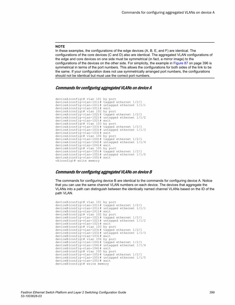
NOTEIn these examples, the configurations of the edge devices (A, B, E, and F) are identical. Theconfigurations of the core devices (C and D) also are identical. The aggregated VLAN configurations ofthe edge and core devices on one side must be symmetrical (in fact, a mirror image) to theconfigurations of the devices on the other side. For simplicity, the example in Figure 87 on page 396 issymmetrical in terms of the port numbers. This allows the configurations for both sides of the link to bethe same. If your configuration does not use symmetrically arranged port numbers, the configurationsshould not be identical but must use the correct port numbers.
Commands for configuring aggregated VLANs on device A
deviceA(config)# vlan 101 by portdeviceA(config-vlan-101)# tagged ethernet 1/2/1deviceA(config-vlan-101)# untagged ethernet 1/1/1deviceA(config-vlan-101)# exitdeviceA(config)# vlan 102 by portdeviceA(config-vlan-102)# tagged ethernet 1/2/1deviceA(config-vlan-102)# untagged ethernet 1/1/2deviceA(config-vlan-102)# exitdeviceA(config)# vlan 103 by portdeviceA(config-vlan-103)# tagged ethernet 1/2/1deviceA(config-vlan-103)# untagged ethernet 1/1/3deviceA(config-vlan-103)# exitdeviceA(config)# vlan 104 by portdeviceA(config-vlan-104)# tagged ethernet 1/2/1deviceA(config-vlan-104)# untagged ethernet 1/1/4deviceA(config-vlan-104)# exitdeviceA(config)# vlan 105 by portdeviceA(config-vlan-105)# tagged ethernet 1/2/1deviceA(config-vlan-105)# untagged ethernet 1/1/5deviceA(config-vlan-105)# exitvA(config)# write memory
Commands for configuring aggregated VLANs on device B
The commands for configuring device B are identical to the commands for configuring device A. Noticethat you can use the same channel VLAN numbers on each device. The devices that aggregate theVLANs into a path can distinguish between the identically named channel VLANs based on the ID of thepath VLAN.
deviceB(config)# vlan 101 by portdeviceB(config-vlan-101)# tagged ethernet 1/2/1deviceB(config-vlan-101)# untagged ethernet 1/1/1deviceB(config-vlan-101)# exitdeviceB(config)# vlan 102 by portdeviceB(config-vlan-102)# tagged ethernet 1/2/1deviceB(config-vlan-102)# untagged ethernet 1/1/2deviceB(config-vlan-102)# exitdeviceB(config)# vlan 103 by portdeviceB(config-vlan-103)# tagged ethernet 1/2/1deviceB(config-vlan-103)# untagged ethernet 1/1/3deviceB(config-vlan-103)# exitdeviceB(config)# vlan 104 by portdeviceB(config-vlan-104)# tagged ethernet 1/2/1deviceB(config-vlan-104)# untagged ethernet 1/1/4deviceB(config-vlan-104)# exitdeviceB(config)# vlan 105 by portdeviceB(config-vlan-105)# tagged ethernet 1/2/1deviceB(config-vlan-105)# untagged ethernet 1/1/5deviceB(config-vlan-105)# exitdeviceB(config)# write memory
Commands for configuring aggregated VLANs on device A
FastIron Ethernet Switch Platform and Layer 2 Switching Configuration Guide 39953-1003628-03
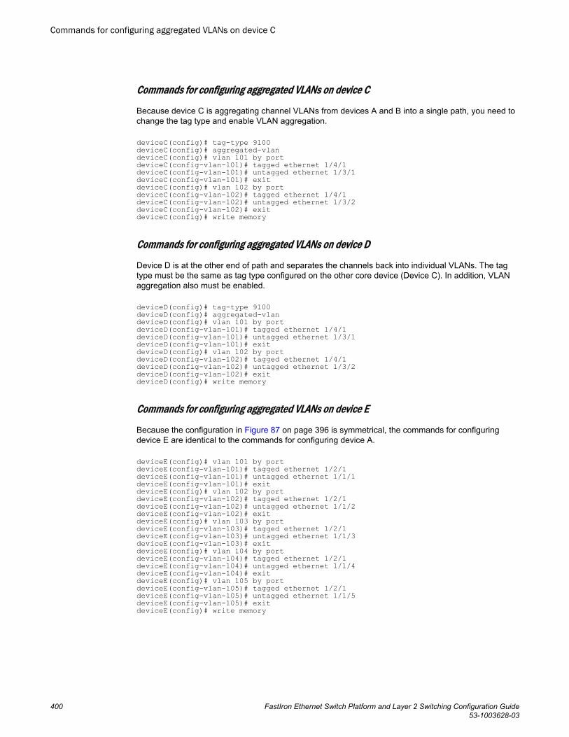
Commands for configuring aggregated VLANs on device C
Because device C is aggregating channel VLANs from devices A and B into a single path, you need tochange the tag type and enable VLAN aggregation.
deviceC(config)# tag-type 9100deviceC(config)# aggregated-vlandeviceC(config)# vlan 101 by portdeviceC(config-vlan-101)# tagged ethernet 1/4/1deviceC(config-vlan-101)# untagged ethernet 1/3/1deviceC(config-vlan-101)# exitdeviceC(config)# vlan 102 by portdeviceC(config-vlan-102)# tagged ethernet 1/4/1deviceC(config-vlan-102)# untagged ethernet 1/3/2deviceC(config-vlan-102)# exitdeviceC(config)# write memory
Commands for configuring aggregated VLANs on device D
Device D is at the other end of path and separates the channels back into individual VLANs. The tagtype must be the same as tag type configured on the other core device (Device C). In addition, VLANaggregation also must be enabled.
deviceD(config)# tag-type 9100deviceD(config)# aggregated-vlandeviceD(config)# vlan 101 by portdeviceD(config-vlan-101)# tagged ethernet 1/4/1deviceD(config-vlan-101)# untagged ethernet 1/3/1deviceD(config-vlan-101)# exitdeviceD(config)# vlan 102 by portdeviceD(config-vlan-102)# tagged ethernet 1/4/1deviceD(config-vlan-102)# untagged ethernet 1/3/2deviceD(config-vlan-102)# exitdeviceD(config)# write memory
Commands for configuring aggregated VLANs on device E
Because the configuration in Figure 87 on page 396 is symmetrical, the commands for configuringdevice E are identical to the commands for configuring device A.
deviceE(config)# vlan 101 by portdeviceE(config-vlan-101)# tagged ethernet 1/2/1deviceE(config-vlan-101)# untagged ethernet 1/1/1deviceE(config-vlan-101)# exitdeviceE(config)# vlan 102 by portdeviceE(config-vlan-102)# tagged ethernet 1/2/1deviceE(config-vlan-102)# untagged ethernet 1/1/2deviceE(config-vlan-102)# exitdeviceE(config)# vlan 103 by portdeviceE(config-vlan-103)# tagged ethernet 1/2/1deviceE(config-vlan-103)# untagged ethernet 1/1/3deviceE(config-vlan-103)# exitdeviceE(config)# vlan 104 by portdeviceE(config-vlan-104)# tagged ethernet 1/2/1deviceE(config-vlan-104)# untagged ethernet 1/1/4deviceE(config-vlan-104)# exitdeviceE(config)# vlan 105 by portdeviceE(config-vlan-105)# tagged ethernet 1/2/1deviceE(config-vlan-105)# untagged ethernet 1/1/5deviceE(config-vlan-105)# exitdeviceE(config)# write memory
Commands for configuring aggregated VLANs on device C
400 FastIron Ethernet Switch Platform and Layer 2 Switching Configuration Guide53-1003628-03
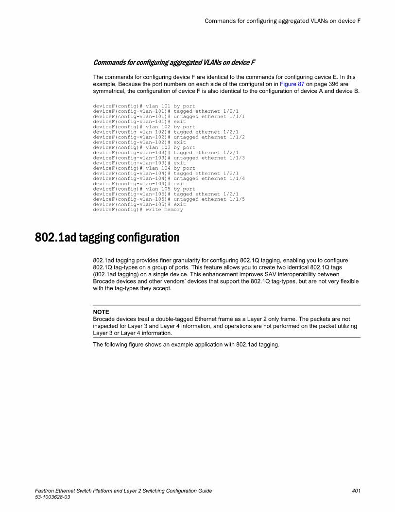
Commands for configuring aggregated VLANs on device F
The commands for configuring device F are identical to the commands for configuring device E. In thisexample, Because the port numbers on each side of the configuration in Figure 87 on page 396 aresymmetrical, the configuration of device F is also identical to the configuration of device A and device B.
deviceF(config)# vlan 101 by portdeviceF(config-vlan-101)# tagged ethernet 1/2/1deviceF(config-vlan-101)# untagged ethernet 1/1/1deviceF(config-vlan-101)# exitdeviceF(config)# vlan 102 by portdeviceF(config-vlan-102)# tagged ethernet 1/2/1deviceF(config-vlan-102)# untagged ethernet 1/1/2deviceF(config-vlan-102)# exitdeviceF(config)# vlan 103 by portdeviceF(config-vlan-103)# tagged ethernet 1/2/1deviceF(config-vlan-103)# untagged ethernet 1/1/3deviceF(config-vlan-103)# exitdeviceF(config)# vlan 104 by portdeviceF(config-vlan-104)# tagged ethernet 1/2/1deviceF(config-vlan-104)# untagged ethernet 1/1/4deviceF(config-vlan-104)# exitdeviceF(config)# vlan 105 by portdeviceF(config-vlan-105)# tagged ethernet 1/2/1deviceF(config-vlan-105)# untagged ethernet 1/1/5deviceF(config-vlan-105)# exitdeviceF(config)# write memory
802.1ad tagging configuration802.1ad tagging provides finer granularity for configuring 802.1Q tagging, enabling you to configure802.1Q tag-types on a group of ports. This feature allows you to create two identical 802.1Q tags(802.1ad tagging) on a single device. This enhancement improves SAV interoperability betweenBrocade devices and other vendors’ devices that support the 802.1Q tag-types, but are not very flexiblewith the tag-types they accept.
NOTEBrocade devices treat a double-tagged Ethernet frame as a Layer 2 only frame. The packets are notinspected for Layer 3 and Layer 4 information, and operations are not performed on the packet utilizingLayer 3 or Layer 4 information.
The following figure shows an example application with 802.1ad tagging.
Commands for configuring aggregated VLANs on device F
FastIron Ethernet Switch Platform and Layer 2 Switching Configuration Guide 40153-1003628-03
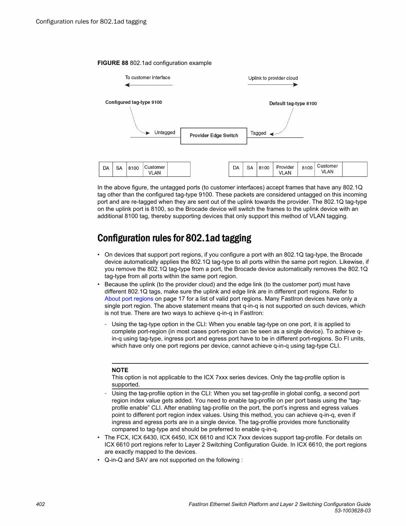
FIGURE 88 802.1ad configuration example
In the above figure, the untagged ports (to customer interfaces) accept frames that have any 802.1Qtag other than the configured tag-type 9100. These packets are considered untagged on this incomingport and are re-tagged when they are sent out of the uplink towards the provider. The 802.1Q tag-typeon the uplink port is 8100, so the Brocade device will switch the frames to the uplink device with anadditional 8100 tag, thereby supporting devices that only support this method of VLAN tagging.
Configuration rules for 802.1ad tagging• On devices that support port regions, if you configure a port with an 802.1Q tag-type, the Brocade
device automatically applies the 802.1Q tag-type to all ports within the same port region. Likewise, ifyou remove the 802.1Q tag-type from a port, the Brocade device automatically removes the 802.1Qtag-type from all ports within the same port region.
• Because the uplink (to the provider cloud) and the edge link (to the customer port) must havedifferent 802.1Q tags, make sure the uplink and edge link are in different port regions. Refer to About port regions on page 17 for a list of valid port regions. Many FastIron devices have only asingle port region. The above statement means that q-in-q is not supported on such devices, whichis not true. There are two ways to achieve q-in-q in FastIron:
‐ Using the tag-type option in the CLI: When you enable tag-type on one port, it is applied tocomplete port-region (in most cases port-region can be seen as a single device). To achieve q-in-q using tag-type, ingress port and egress port have to be in different port-regions. So FI units,which have only one port regions per device, cannot achieve q-in-q using tag-type CLI.
NOTEThis option is not applicable to the ICX 7xxx series devices. Only the tag-profile option issupported.
‐ Using the tag-profile option in the CLI: When you set tag-profile in global config, a second portregion index value gets added. You need to enable tag-profile on per port basis using the “tag-profile enable” CLI. After enabling tag-profile on the port, the port’s ingress and egress valuespoint to different port region index values. Using this method, you can achieve q-in-q, even ifingress and egress ports are in a single device. The tag-profile provides more functionalitycompared to tag-type and should be preferred to enable q-in-q.
• The FCX, ICX 6430, ICX 6450, ICX 6610 and ICX 7xxx devices support tag-profile. For details onICX 6610 port regions refer to Layer 2 Switching Configuration Guide. In ICX 6610, the port regionsare exactly mapped to the devices.
• Q-in-Q and SAV are not supported on the following :
Configuration rules for 802.1ad tagging
402 FastIron Ethernet Switch Platform and Layer 2 Switching Configuration Guide53-1003628-03
‐ 48-port 10/100/1000 Mbps (RJ45) Ethernet POE interface module (SX-FI48GPP)‐ 2-port 10-Gigabit Ethernet interface module (SX-FI-2XG)‐ 8-port 10-Gigabit Ethernet interface module (SX-FI-8XG)‐ 24-port Gigabit Ethernet fiber interface module (SX-FI-24HF)‐ 24-port Gigabit Ethernet copper interface module with PoE+ (SX-FI-24GPP)‐ ICX6430C devices.
• FastIron X Series devices support one configured tag-type per device along with the default tag-typeof 8100. For example, if you configure an 802.1Q tag of 9100 on ports 1 - 12, then later configure an802.1Q tag of 5100 on port 15, the device automatically applies the 5100 tag to all ports in the sameport region as port 15, and also changes the 802.1Q tag-type on ports 1 - 12 to 5100.
• 802.1ad tagging and VSRP are not supported together on the same device.• In addition to tag-type Brocade FCX and ICX devices support tag-profile. For more information,
refer to Configuring 802.1ad tag profiles on page 404 .
Enabling 802.1ad taggingTo enable 802.1ad tagging, configure an 802.1Q tag on the untagged edge links (the customer ports) toany value other than the 802.1Q tag for incoming traffic. For example, in Figure 89 on page 404, the802.1Q tag on the untagged edge links (ports 11 and 12) is 9100, whereas, the 802.1Q tag for incomingtraffic is 8100.
To configure 802.1 ad tagging as shown in Figure 89 on page 404, enter commands such as thefollowing on the untagged edge links of devices C and D.
device(config)# tag-type 9100 ethernet 11 to 12device(config)# aggregated-vlanNote that because ports 11 and 12 belong to the port region 1 - 12, the 802.1Q tag actually applies toports 1 - 12.
Syntax: [no] tag-type num [ethernet port [to port]]
The ethernet port to port parameter specifies the ports that will use the defined 802.1Q tag. Thisparameter operates with the following rules:
• If you specify a single port number, the 802.1Q tag applies to all ports within the port region. Forexample, if you enter the command tag-type 9100 ethernet 1 , the Brocade device automaticallyapplies the 802.1Q tag to ports 1 - 12 because all of these ports are in the same port region. You canuse the show running-config command to view how the command has been applied.
• If you do not specify a port or range of ports, the 802.1Q tag applies to all Ethernet ports on thedevice.
Example 802.1ad configurationThe following figure shows an example 802.1ad configuration.
Enabling 802.1ad tagging
FastIron Ethernet Switch Platform and Layer 2 Switching Configuration Guide 40353-1003628-03
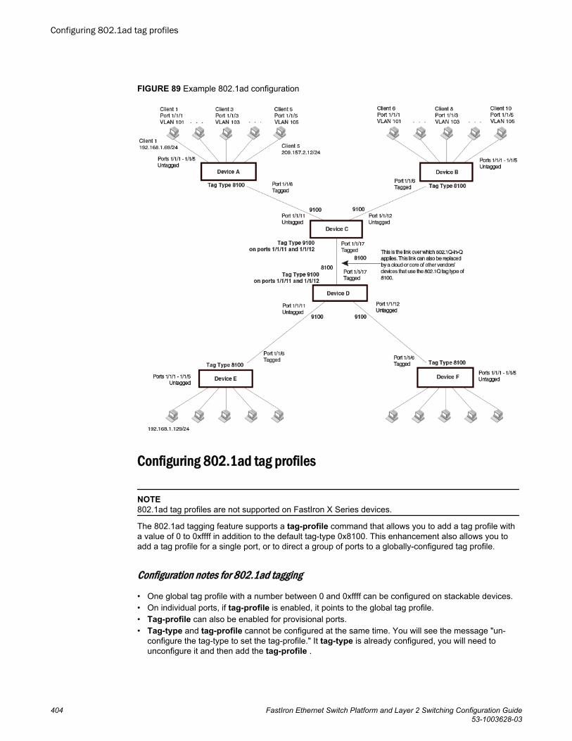
FIGURE 89 Example 802.1ad configuration
Configuring 802.1ad tag profiles
NOTE802.1ad tag profiles are not supported on FastIron X Series devices.
The 802.1ad tagging feature supports a tag-profile command that allows you to add a tag profile witha value of 0 to 0xffff in addition to the default tag-type 0x8100. This enhancement also allows you toadd a tag profile for a single port, or to direct a group of ports to a globally-configured tag profile.
Configuration notes for 802.1ad tagging
• One global tag profile with a number between 0 and 0xffff can be configured on stackable devices.• On individual ports, if tag-profile is enabled, it points to the global tag profile.• Tag-profile can also be enabled for provisional ports.• Tag-type and tag-profile cannot be configured at the same time. You will see the message "un-
configure the tag-type to set the tag-profile." It tag-type is already configured, you will need tounconfigure it and then add the tag-profile .
Configuring 802.1ad tag profiles
404 FastIron Ethernet Switch Platform and Layer 2 Switching Configuration Guide53-1003628-03
• Do not use the tag-type command in conjunction with the tag-profile command. If a tag-type hasalready been configured and you try to use the tag-profile command, you will see an error messagetelling you to remove the tag-type before you add the tag-profile.
• For devices operating in an IronStack topology, when a tag-type for a port is changed, the tag-typefor all of the ports on a stack unit also changes. Because of this limitation, SAV and Q-in-Q cannot beused at the same time on stacking devices.
CLI Syntax for 802.1ad tagging
To add a global tag-profile enter the following command.
device(config)# tag-profile 9500This command adds a profile in addition to the default profile of 0x8100.
Syntax: [no] tag-profile tag-no
where tag-no can be 0x8100 (the default) or 0xffff.
To enable the new profile on individual ports, enter commands similar to the following.
device(config)# interface ethernet 1/1/1device(config-if-e1000-1/1/1)# tag-profile enabledevice(config-mif-1/1/1,1/2/1)# tag-profile enableSyntax: [no] tag-profile enable
Private VLAN configurationA private VLAN (PVLAN) is a VLAN that has the properties of standard Layer 2 port-based VLANs butalso provides additional control over flooding packets on a VLAN. The following table shows anexample of an application using a PVLAN.
CLI Syntax for 802.1ad tagging
FastIron Ethernet Switch Platform and Layer 2 Switching Configuration Guide 40553-1003628-03
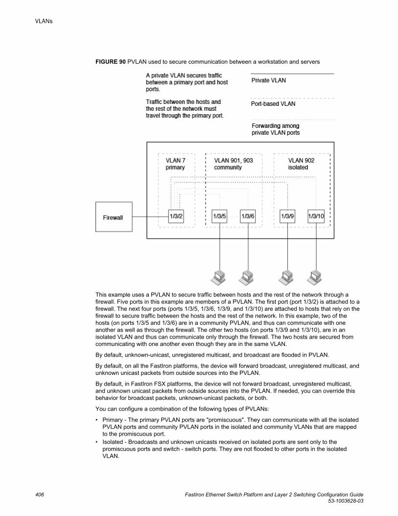
FIGURE 90 PVLAN used to secure communication between a workstation and servers
This example uses a PVLAN to secure traffic between hosts and the rest of the network through afirewall. Five ports in this example are members of a PVLAN. The first port (port 1/3/2) is attached to afirewall. The next four ports (ports 1/3/5, 1/3/6, 1/3/9, and 1/3/10) are attached to hosts that rely on thefirewall to secure traffic between the hosts and the rest of the network. In this example, two of thehosts (on ports 1/3/5 and 1/3/6) are in a community PVLAN, and thus can communicate with oneanother as well as through the firewall. The other two hosts (on ports 1/3/9 and 1/3/10), are in anisolated VLAN and thus can communicate only through the firewall. The two hosts are secured fromcommunicating with one another even though they are in the same VLAN.
By default, unknown-unicast, unregistered multicast, and broadcast are flooded in PVLAN.
By default, on all the FastIron platforms, the device will forward broadcast, unregistered multicast, andunknown unicast packets from outside sources into the PVLAN.
By default, in FastIron FSX platforms, the device will not forward broadcast, unregistered multicast,and unknown unicast packets from outside sources into the PVLAN. If needed, you can override thisbehavior for broadcast packets, unknown-unicast packets, or both.
You can configure a combination of the following types of PVLANs:
• Primary - The primary PVLAN ports are "promiscuous". They can communicate with all the isolatedPVLAN ports and community PVLAN ports in the isolated and community VLANs that are mappedto the promiscuous port.
• Isolated - Broadcasts and unknown unicasts received on isolated ports are sent only to thepromiscuous ports and switch - switch ports. They are not flooded to other ports in the isolatedVLAN.
VLANs
406 FastIron Ethernet Switch Platform and Layer 2 Switching Configuration Guide53-1003628-03
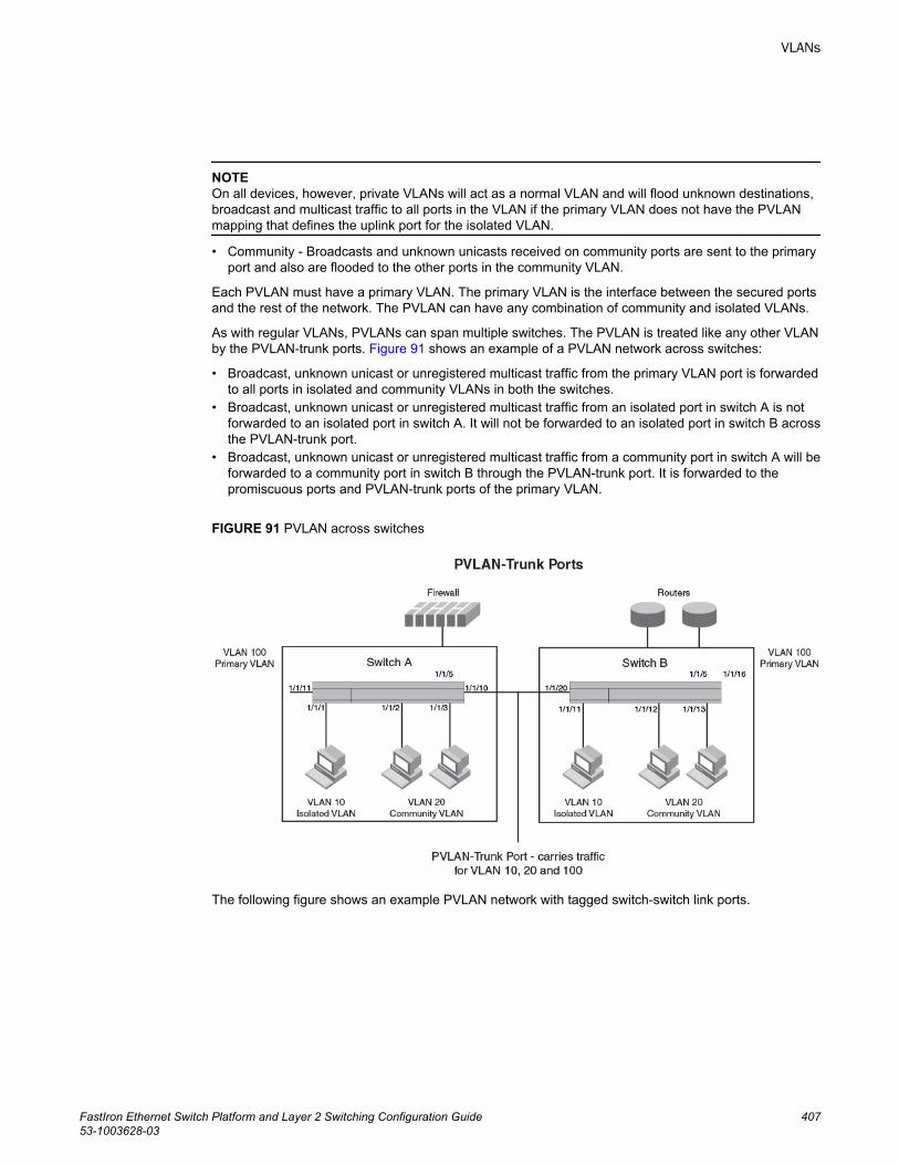
NOTEOn all devices, however, private VLANs will act as a normal VLAN and will flood unknown destinations,broadcast and multicast traffic to all ports in the VLAN if the primary VLAN does not have the PVLANmapping that defines the uplink port for the isolated VLAN.
• Community - Broadcasts and unknown unicasts received on community ports are sent to the primaryport and also are flooded to the other ports in the community VLAN.
Each PVLAN must have a primary VLAN. The primary VLAN is the interface between the secured portsand the rest of the network. The PVLAN can have any combination of community and isolated VLANs.
As with regular VLANs, PVLANs can span multiple switches. The PVLAN is treated like any other VLANby the PVLAN-trunk ports. Figure 91 shows an example of a PVLAN network across switches:
• Broadcast, unknown unicast or unregistered multicast traffic from the primary VLAN port is forwardedto all ports in isolated and community VLANs in both the switches.
• Broadcast, unknown unicast or unregistered multicast traffic from an isolated port in switch A is notforwarded to an isolated port in switch A. It will not be forwarded to an isolated port in switch B acrossthe PVLAN-trunk port.
• Broadcast, unknown unicast or unregistered multicast traffic from a community port in switch A will beforwarded to a community port in switch B through the PVLAN-trunk port. It is forwarded to thepromiscuous ports and PVLAN-trunk ports of the primary VLAN.
FIGURE 91 PVLAN across switches
The following figure shows an example PVLAN network with tagged switch-switch link ports.
VLANs
FastIron Ethernet Switch Platform and Layer 2 Switching Configuration Guide 40753-1003628-03
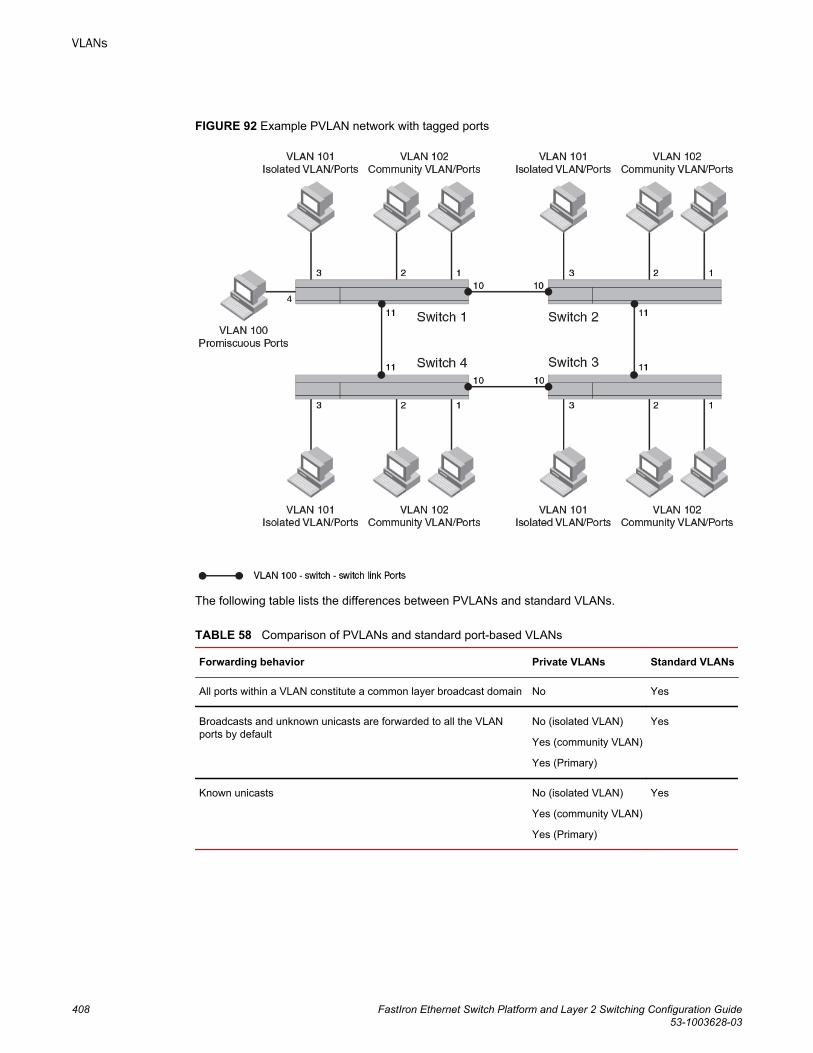
FIGURE 92 Example PVLAN network with tagged ports
The following table lists the differences between PVLANs and standard VLANs.
Comparison of PVLANs and standard port-based VLANs TABLE 58
Forwarding behavior Private VLANs Standard VLANs
All ports within a VLAN constitute a common layer broadcast domain No Yes
Broadcasts and unknown unicasts are forwarded to all the VLANports by default
No (isolated VLAN)
Yes (community VLAN)
Yes (Primary)
Yes
Known unicasts No (isolated VLAN)
Yes (community VLAN)
Yes (Primary)
Yes
VLANs
408 FastIron Ethernet Switch Platform and Layer 2 Switching Configuration Guide53-1003628-03
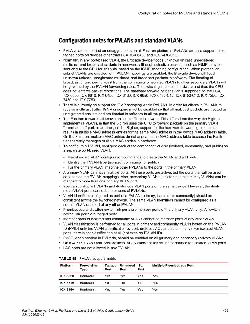
Configuration notes for PVLANs and standard VLANs• PVLANs are supported on untagged ports on all FastIron platforms. PVLANs are also supported on
tagged ports on devices other than FSX, ICX 6430 and ICX 6430-C12.• Normally, in any port-based VLAN, the Brocade device floods unknown unicast, unregistered
multicast, and broadcast packets in hardware, although selective packets, such as IGMP, may besent only to the CPU for analysis, based on the IGMP snooping configuration. When protocol orsubnet VLANs are enabled, or if PVLAN mappings are enabled, the Brocade device will floodunknown unicast, unregistered multicast, and broadcast packets in software. The flooding ofbroadcast or unknown unicast from the community or isolated VLANs to other secondary VLANs willbe governed by the PVLAN forwarding rules. The switching is done in hardware and thus the CPUdoes not enforce packet restrictions. The hardware forwarding behavior is supported on the FCX,ICX 6650, ICX 6610, ICX 6450, ICX 6430, ICX 6650, ICX 6430-C12, ICX 6450-C12, ICX 7250, ICX7450 and ICX 7750.
• There is currently no support for IGMP snooping within PVLANs. In order for clients in PVLANs toreceive multicast traffic, IGMP snooping must be disabled so that all multicast packets are treated asunregistered packets and are flooded in software to all the ports.
• The FastIron forwards all known unicast traffic in hardware. This differs from the way the BigIronimplements PVLANs, in that the BigIron uses the CPU to forward packets on the primary VLAN"promiscuous" port. In addition, on the BigIron, support for the hardware forwarding sometimesresults in multiple MAC address entries for the same MAC address in the device MAC address table.On the FastIron, multiple MAC entries do not appear in the MAC address table because the FastIrontransparently manages multiple MAC entries in hardware.
• To configure a PVLAN, configure each of the component VLANs (isolated, community, and public) asa separate port-based VLAN:
‐ Use standard VLAN configuration commands to create the VLAN and add ports.‐ Identify the PVLAN type (isolated, community, or public)‐ For the primary VLAN, map the other PVLANs to the ports in the primary VLAN
• A primary VLAN can have multiple ports. All these ports are active, but the ports that will be useddepends on the PVLAN mappings. Also, secondary VLANs (isolated and community VLANs) can bemapped to more than one primary VLAN port.
• You can configure PVLANs and dual-mode VLAN ports on the same device. However, the dual-mode VLAN ports cannot be members of PVLANs.
• VLAN identifiers configured as part of a PVLAN (primary, isolated, or community) should beconsistent across the switched network. The same VLAN identifiers cannot be configured as anormal VLAN or a part of any other PVLAN.
• Promiscuous and switch-switch link ports are member ports of the primary VLAN only. All switch-switch link ports are tagged ports.
• Member ports of isolated and community VLANs cannot be member ports of any other VLAN.• VLAN classification is performed for all ports in primary and community VLANs based on the PVLAN
ID (PVID) only (no VLAN classification by port, protocol, ACL and so on, if any). For isolated VLANports there is not classification at all (not even on PVLAN ID).
• PVST, when needed in PVLANs, should be enabled on all (primary and secondary) private VLANs.• On ICX 7750, 7450 and 7250 devices, VLAN classification will be performed for isolated VLAN ports.• LAG ports are not allowed in any PVLAN.
PVLAN support matrix TABLE 59
Platform ForwardingType
TaggedPort
UntaggedPort
ISLPort
Multiple Promiscuous Port
ICX-6650 Hardware Yes Yes Yes Yes
ICX-6610 Hardware Yes Yes Yes Yes
ICX-6450 Hardware Yes Yes Yes Yes
Configuration notes for PVLANs and standard VLANs
FastIron Ethernet Switch Platform and Layer 2 Switching Configuration Guide 40953-1003628-03
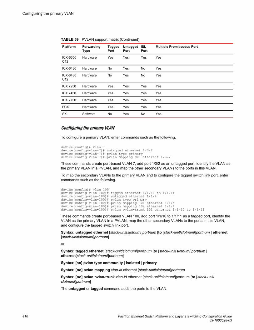
PVLAN support matrix (Continued)TABLE 59
Platform ForwardingType
TaggedPort
UntaggedPort
ISLPort
Multiple Promiscuous Port
ICX-6650C12
Hardware Yes Yes Yes Yes
ICX-6430 Hardware No Yes No Yes
ICX-6430C12
Hardware No Yes No Yes
ICX 7250 Hardware Yes Yes Yes Yes
ICX 7450 Hardware Yes Yes Yes Yes
ICX 7750 Hardware Yes Yes Yes Yes
FCX Hardware Yes Yes Yes Yes
SXL Software No Yes No Yes
Configuring the primary VLAN
To configure a primary VLAN, enter commands such as the following.
device(config)# vlan 7device(config-vlan-7)# untagged ethernet 1/3/2device(config-vlan-7)# pvlan type primarydevice(config-vlan-7)# pvlan mapping 901 ethernet 1/3/2These commands create port-based VLAN 7, add port 1/3/2 as an untagged port, identify the VLAN asthe primary VLAN in a PVLAN, and map the other secondary VLANs to the ports in this VLAN.
To map the secondary VLANs to the primary VLAN and to configure the tagged switch link port, entercommands such as the following.
device(config)# vlan 100device(config-vlan-100)# tagged ethernet 1/1/10 to 1/1/11device(config-vlan-100)# untagged ethernet 1/1/4device(config-vlan-100)# pvlan type primarydevice(config-vlan-100)# pvlan mapping 101 ethernet 1/1/4device(config-vlan-100)# pvlan mapping 102 ethernet 1/1/4device(config-vlan-100)# pvlan pvlan-trunk 101 ethernet 1/1/10 to 1/1/11These commands create port-based VLAN 100, add port 1/1/10 to 1/1/11 as a tagged port, identify theVLAN as the primary VLAN in a PVLAN, map the other secondary VLANs to the ports in this VLAN,and configure the tagged switch link port.
Syntax: untagged ethernet [stack-unit/slotnum/]portnum [to [stack-unit/slotnum/]portnum | ethernet[stack-unit/slotnum/]portnum]
or
Syntax: tagged ethernet [stack-unit/slotnum/]portnum [to [stack-unit/slotnum/]portnum |ethernet[stack-unit/slotnum/]portnum]
Syntax: [no] pvlan type community | isolated | primary
Syntax: [no] pvlan mapping vlan-id ethernet [stack-unit/slotnum/]portnum
Syntax: [no] pvlan pvlan-trunk vlan-id ethernet [stack-unit/slotnum/]portnum [to [stack-unit/slotnum/]portnum]
The untagged or tagged command adds the ports to the VLAN.
Configuring the primary VLAN
410 FastIron Ethernet Switch Platform and Layer 2 Switching Configuration Guide53-1003628-03
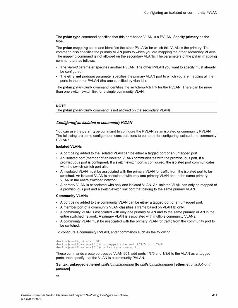
The pvlan type command specifies that this port-based VLAN is a PVLAN. Specify primary as thetype.
The pvlan mapping command identifies the other PVLANs for which this VLAN is the primary. Thecommand also specifies the primary VLAN ports to which you are mapping the other secondary VLANs.The mapping command is not allowed on the secondary VLANs. The parameters of the pvlan mappingcommand are as follows:
• The vlan-id parameter specifies another PVLAN. The other PVLAN you want to specify must alreadybe configured.
• The ethernet portnum parameter specifies the primary VLAN port to which you are mapping all theports in the other PVLAN (the one specified by vlan-id ).
The pvlan pvlan-trunk command identifies the switch-switch link for the PVLAN. There can be morethan one switch-switch link for a single community VLAN.
NOTEThe pvlan pvlan-trunk command is not allowed on the secondary VLANs.
Configuring an isolated or community PVLAN
You can use the pvlan type command to configure the PVLAN as an isolated or community PVLAN.The following are some configuration considerations to be noted for configuring isolated and communityPVLANs.
Isolated VLANs
• A port being added to the isolated VLAN can be either a tagged port or an untagged port.• An isolated port (member of an isolated VLAN) communicates with the promiscuous port, if a
promiscuous port is configured. If a switch-switch port is configured, the isolated port communicateswith the switch-switch port also.
• An isolated VLAN must be associated with the primary VLAN for traffic from the isolated port to beswitched. An isolated VLAN is associated with only one primary VLAN and to the same primaryVLAN in the entire switched network.
• A primary VLAN is associated with only one isolated VLAN. An isolated VLAN can only be mapped toa promiscuous port and a switch-switch link port that belong to the same primary VLAN.
Community VLANs
• A port being added to the community VLAN can be either a tagged port or an untagged port.• A member port of a community VLAN classifies a frame based on VLAN ID only.• A community VLAN is associated with only one primary VLAN and to the same primary VLAN in the
entire switched network. A primary VLAN is associated with multiple community VLANs.• A community VLAN must be associated with the primary VLAN for traffic from the community port to
be switched.
To configure a community PVLAN, enter commands such as the following.
device(config)# vlan 901device(config-vlan-901)# untagged ethernet 1/3/5 to 1/3/6device(config-vlan-901)# pvlan type communityThese commands create port-based VLAN 901, add ports 1/3/5 and 1/3/6 to the VLAN as untaggedports, then specify that the VLAN is a community PVLAN.
Syntax: untagged ethernet unit/slotnum/portnum [to unit/slotnum/portnum | ethernet unit/slotnum/portnum]
or
Configuring an isolated or community PVLAN
FastIron Ethernet Switch Platform and Layer 2 Switching Configuration Guide 41153-1003628-03
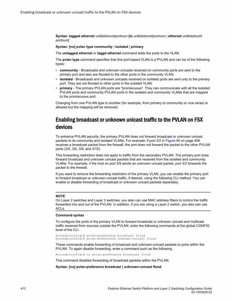
Syntax: tagged ethernet unit/slotnum/portnum [to unit/slotnum/portnum | ethernet unit/slotnum/portnum]
Syntax: [no] pvlan type community | isolated | primary
The untagged ethernet or taggd ethernet command adds the ports to the VLAN.
The pvlan type command specifies that this port-based VLAN is a PVLAN and can be of the followingtypes:
• community - Broadcasts and unknown unicasts received on community ports are sent to theprimary port and also are flooded to the other ports in the community VLAN.
• isolated - Broadcasts and unknown unicasts received on isolated ports are sent only to the primaryport. They are not flooded to other ports in the isolated VLAN.
• primary - The primary PVLAN ports are "promiscuous". They can communicate with all the isolatedPVLAN ports and community PVLAN ports in the isolated and community VLANs that are mappedto the promiscuous port.
Changing from one PVLAN type to another (for example, from primary to community or vice versa) isallowed but the mapping will be removed.
Enabling broadcast or unknown unicast traffic to the PVLAN on FSXdevicesTo enhance PVLAN security, the primary PVLAN does not forward broadcast or unknown unicastpackets to its community and isolated VLANs. For example, if port 3/2 in Figure 90 on page 406receives a broadcast packet from the firewall, the port does not forward the packet to the other PVLANports (3/5, 3/6, 3/9, and 3/10).
This forwarding restriction does not apply to traffic from the secondary PVLAN. The primary port doesforward broadcast and unknown unicast packets that are received from the isolated and communityVLANs. For example, if the host on port 3/9 sends an unknown unicast packet, port 3/2 forwards thepacket to the firewall.
If you want to remove the forwarding restriction of the primary VLAN, you can enable the primary portto forward broadcast or unknown unicast traffic, if desired, using the following CLI method. You canenable or disable forwarding of broadcast or unknown unicast packets separately.
NOTEOn Layer 2 switches and Layer 3 switches, you also can use MAC address filters to control the trafficforwarded into and out of the PVLAN. In addition, if you are using a Layer 2 switch, you also can useACLs.
Command syntax
To configure the ports in the primary VLAN to forward broadcast or unknown unicast and multicasttraffic received from sources outside the PVLAN, enter the following commands at the global CONFIGlevel of the CLI.Brocade(config)# pvlan-preference broadcast floodBrocade(config)# pvlan-preference unknown-unicast floodThese commands enable forwarding of broadcast and unknown-unicast packets to ports within thePVLAN. To again disable forwarding, enter a command such as the following.Brocade(config)# no pvlan-preference broadcast floodThis command disables forwarding of broadcast packets within the PVLAN.
Syntax: [no] pvlan-preference broadcast | unknown-unicast flood
Enabling broadcast or unknown unicast traffic to the PVLAN on FSX devices
412 FastIron Ethernet Switch Platform and Layer 2 Switching Configuration Guide53-1003628-03
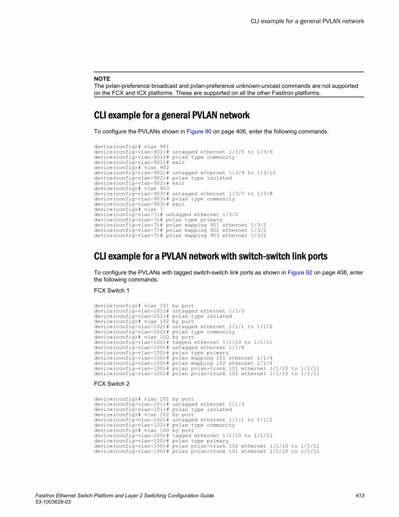
NOTEThe pvlan-preference broadcast and pvlan-preference unknown-unicast commands are not supportedon the FCX and ICX platforms. These are supported on all the other FastIron platforms.
CLI example for a general PVLAN networkTo configure the PVLANs shown in Figure 90 on page 406, enter the following commands.
device(config)# vlan 901device(config-vlan-901)# untagged ethernet 1/3/5 to 1/3/6device(config-vlan-901)# pvlan type communitydevice(config-vlan-901)# exitdevice(config)# vlan 902device(config-vlan-902)# untagged ethernet 1/3/9 to 1/3/10device(config-vlan-902)# pvlan type isolateddevice(config-vlan-902)# exitdevice(config)# vlan 903device(config-vlan-903)# untagged ethernet 1/3/7 to 1/3/8device(config-vlan-903)# pvlan type communitydevice(config-vlan-903)# exitdevice(config)# vlan 7device(config-vlan-7)# untagged ethernet 1/3/2device(config-vlan-7)# pvlan type primarydevice(config-vlan-7)# pvlan mapping 901 ethernet 1/3/2device(config-vlan-7)# pvlan mapping 902 ethernet 1/3/2device(config-vlan-7)# pvlan mapping 903 ethernet 1/3/2
CLI example for a PVLAN network with switch-switch link portsTo configure the PVLANs with tagged switch-switch link ports as shown in Figure 92 on page 408, enterthe following commands.
FCX Switch 1
device(config)# vlan 101 by portdevice(config-vlan-101)# untagged ethernet 1/1/3device(config-vlan-101)# pvlan type isolateddevice(config)# vlan 102 by portdevice(config-vlan-102)# untagged ethernet 1/1/1 to 1/1/2device(config-vlan-102)# pvlan type communitydevice(config)# vlan 100 by portdevice(config-vlan-100)# tagged ethernet 1/1/10 to 1/1/11device(config-vlan-100)# untagged ethernet 1/1/4device(config-vlan-100)# pvlan type primarydevice(config-vlan-100)# pvlan mapping 101 ethernet 1/1/4device(config-vlan-100)# pvlan mapping 102 ethernet 1/1/4device(config-vlan-100)# pvlan pvlan-trunk 101 ethernet 1/1/10 to 1/1/11device(config-vlan-100)# pvlan pvlan-trunk 102 ethernet 1/1/10 to 1/1/11FCX Switch 2
device(config)# vlan 101 by portdevice(config-vlan-101)# untagged ethernet 1/1/3device(config-vlan-101)# pvlan type isolateddevice(config)# vlan 102 by portdevice(config-vlan-102)# untagged ethernet 1/1/1 to 1/1/2device(config-vlan-102)# pvlan type communitydevice(config)# vlan 100 by portdevice(config-vlan-100)# tagged ethernet 1/1/10 to 1/1/11device(config-vlan-100)# pvlan type primarydevice(config-vlan-100)# pvlan pvlan-trunk 102 ethernet 1/1/10 to 1/1/11device(config-vlan-100)# pvlan pvlan-trunk 101 ethernet 1/1/10 to 1/1/11
CLI example for a general PVLAN network
FastIron Ethernet Switch Platform and Layer 2 Switching Configuration Guide 41353-1003628-03
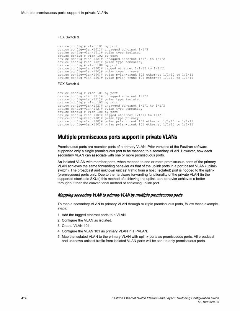
FCX Switch 3
device(config)# vlan 101 by portdevice(config-vlan-101)# untagged ethernet 1/1/3device(config-vlan-101)# pvlan type isolateddevice(config)# vlan 102 by portdevice(config-vlan-102)# untagged ethernet 1/1/1 to 1/1/2device(config-vlan-102)# pvlan type communitydevice(config)# vlan 100 by portdevice(config-vlan-100)# tagged ethernet 1/1/10 to 1/1/11device(config-vlan-100)# pvlan type primarydevice(config-vlan-100)# pvlan pvlan-trunk 102 ethernet 1/1/10 to 1/1/11device(config-vlan-100)# pvlan pvlan-trunk 101 ethernet 1/1/10 to 1/1/11FCX Switch 4
device(config)# vlan 101 by portdevice(config-vlan-101)# untagged ethernet 1/1/3device(config-vlan-101)# pvlan type isolateddevice(config)# vlan 102 by portdevice(config-vlan-102)# untagged ethernet 1/1/1 to 1/1/2device(config-vlan-102)# pvlan type communitydevice(config)# vlan 100 by portdevice(config-vlan-100)# tagged ethernet 1/1/10 to 1/1/11device(config-vlan-100)# pvlan type primarydevice(config-vlan-100)# pvlan pvlan-trunk 102 ethernet 1/1/10 to 1/1/11device(config-vlan-100)# pvlan pvlan-trunk 101 ethernet 1/1/10 to 1/1/11
Multiple promiscuous ports support in private VLANsPromiscuous ports are member ports of a primary VLAN. Prior versions of the FastIron softwaresupported only a single promiscuous port to be mapped to a secondary VLAN. However, now eachsecondary VLAN can associate with one or more promiscuous ports.
An isolated VLAN with member ports, when mapped to one or more promiscuous ports of the primaryVLAN achieves the same forwarding behavior as that of the uplink ports in a port based VLAN (uplink-switch). The broadcast and unknown unicast traffic from a host (isolated) port is flooded to the uplink(promiscuous) ports only. Due to the hardware forwarding functionality of the private VLAN (in thesupported stackable SKUs) this method of achieving the uplink port behavior achieves a betterthroughput than the conventional method of achieving uplink port.
Mapping secondary VLAN to primary VLAN by multiple promiscuous ports
To map a secondary VLAN to primary VLAN through multiple promiscuous ports, follow these examplesteps:
1. Add the tagged ethernet ports to a VLAN.2. Configure the VLAN as isolated.3. Create VLAN 101.4. Configure the VLAN 101 as primary VLAN in a PVLAN.5. Map the isolated VLAN to the primary VLAN with uplink-ports as promiscuous ports. All broadcast
and unknown-unicast traffic from isolated VLAN ports will be sent to only promiscuous ports.
Multiple promiscuous ports support in private VLANs
414 FastIron Ethernet Switch Platform and Layer 2 Switching Configuration Guide53-1003628-03
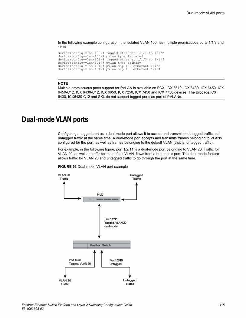
In the following example configuration, the isolated VLAN 100 has multiple promiscuous ports 1/1/3 and1/1/4.device(config-vlan-100)# tagged ethernet 1/1/1 to 1/1/2device(config-vlan-100)# pvlan type isolateddevice(config-vlan-101)# tagged ethernet 1/1/3 to 1/1/5device(config-vlan-101)# pvlan type primarydevice(config-vlan-101)# pvlan map 100 ethernet 1/1/3device(config-vlan-101)# pvlan map 100 ethernet 1/1/4
NOTEMultiple promiscuous ports support for PVLAN is available on FCX, ICX 6610, ICX 6430, ICX 6450, ICX6450-C12, ICX 6430-C12, ICX 6650, ICX 7250, ICX 7450 and ICX 7750 devices. The Brocade ICX6430, ICX6430-C12 and SXL do not support tagged ports as part of PVLANs.
Dual-mode VLAN ports
Configuring a tagged port as a dual-mode port allows it to accept and transmit both tagged traffic anduntagged traffic at the same time. A dual-mode port accepts and transmits frames belonging to VLANsconfigured for the port, as well as frames belonging to the default VLAN (that is, untagged traffic).
For example, in the following figure, port 1/2/11 is a dual-mode port belonging to VLAN 20. Traffic forVLAN 20, as well as traffic for the default VLAN, flows from a hub to this port. The dual-mode featureallows traffic for VLAN 20 and untagged traffic to go through the port at the same time.
FIGURE 93 Dual-mode VLAN port example
Dual-mode VLAN ports
FastIron Ethernet Switch Platform and Layer 2 Switching Configuration Guide 41553-1003628-03
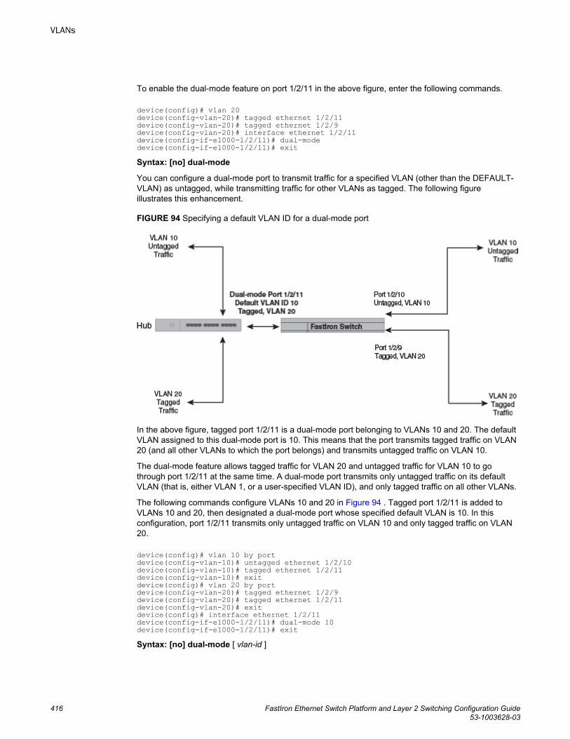
To enable the dual-mode feature on port 1/2/11 in the above figure, enter the following commands.
device(config)# vlan 20device(config-vlan-20)# tagged ethernet 1/2/11device(config-vlan-20)# tagged ethernet 1/2/9device(config-vlan-20)# interface ethernet 1/2/11device(config-if-e1000-1/2/11)# dual-modedevice(config-if-e1000-1/2/11)# exitSyntax: [no] dual-mode
You can configure a dual-mode port to transmit traffic for a specified VLAN (other than the DEFAULT-VLAN) as untagged, while transmitting traffic for other VLANs as tagged. The following figureillustrates this enhancement.
FIGURE 94 Specifying a default VLAN ID for a dual-mode port
In the above figure, tagged port 1/2/11 is a dual-mode port belonging to VLANs 10 and 20. The defaultVLAN assigned to this dual-mode port is 10. This means that the port transmits tagged traffic on VLAN20 (and all other VLANs to which the port belongs) and transmits untagged traffic on VLAN 10.
The dual-mode feature allows tagged traffic for VLAN 20 and untagged traffic for VLAN 10 to gothrough port 1/2/11 at the same time. A dual-mode port transmits only untagged traffic on its defaultVLAN (that is, either VLAN 1, or a user-specified VLAN ID), and only tagged traffic on all other VLANs.
The following commands configure VLANs 10 and 20 in Figure 94 . Tagged port 1/2/11 is added toVLANs 10 and 20, then designated a dual-mode port whose specified default VLAN is 10. In thisconfiguration, port 1/2/11 transmits only untagged traffic on VLAN 10 and only tagged traffic on VLAN20.
device(config)# vlan 10 by portdevice(config-vlan-10)# untagged ethernet 1/2/10device(config-vlan-10)# tagged ethernet 1/2/11device(config-vlan-10)# exitdevice(config)# vlan 20 by portdevice(config-vlan-20)# tagged ethernet 1/2/9device(config-vlan-20)# tagged ethernet 1/2/11device(config-vlan-20)# exitdevice(config)# interface ethernet 1/2/11device(config-if-e1000-1/2/11)# dual-mode 10device(config-if-e1000-1/2/11)# exitSyntax: [no] dual-mode [ vlan-id ]
VLANs
416 FastIron Ethernet Switch Platform and Layer 2 Switching Configuration Guide53-1003628-03
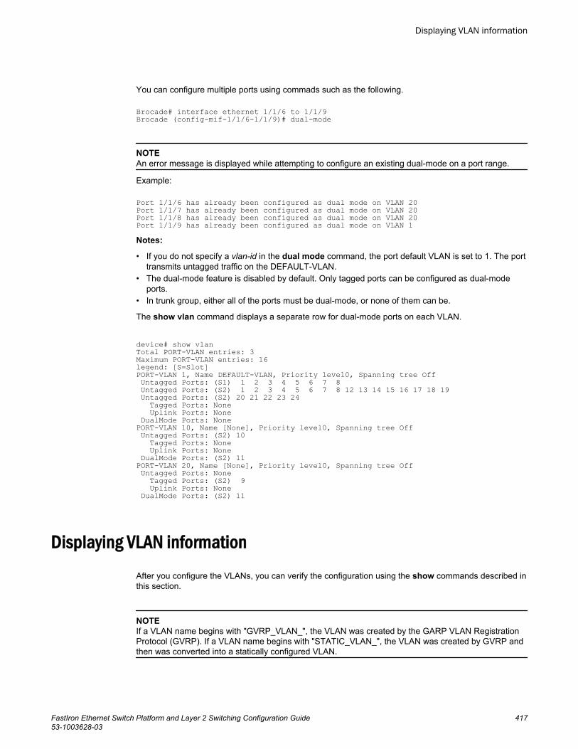
You can configure multiple ports using commads such as the following.
Brocade# interface ethernet 1/1/6 to 1/1/9 Brocade (config-mif-1/1/6-1/1/9)# dual-mode
NOTEAn error message is displayed while attempting to configure an existing dual-mode on a port range.
Example:
Port 1/1/6 has already been configured as dual mode on VLAN 20Port 1/1/7 has already been configured as dual mode on VLAN 20Port 1/1/8 has already been configured as dual mode on VLAN 20Port 1/1/9 has already been configured as dual mode on VLAN 1Notes:
• If you do not specify a vlan-id in the dual mode command, the port default VLAN is set to 1. The porttransmits untagged traffic on the DEFAULT-VLAN.
• The dual-mode feature is disabled by default. Only tagged ports can be configured as dual-modeports.
• In trunk group, either all of the ports must be dual-mode, or none of them can be.
The show vlan command displays a separate row for dual-mode ports on each VLAN.
device# show vlanTotal PORT-VLAN entries: 3Maximum PORT-VLAN entries: 16legend: [S=Slot]PORT-VLAN 1, Name DEFAULT-VLAN, Priority level0, Spanning tree Off Untagged Ports: (S1) 1 2 3 4 5 6 7 8 Untagged Ports: (S2) 1 2 3 4 5 6 7 8 12 13 14 15 16 17 18 19 Untagged Ports: (S2) 20 21 22 23 24 Tagged Ports: None Uplink Ports: None DualMode Ports: NonePORT-VLAN 10, Name [None], Priority level0, Spanning tree Off Untagged Ports: (S2) 10 Tagged Ports: None Uplink Ports: None DualMode Ports: (S2) 11PORT-VLAN 20, Name [None], Priority level0, Spanning tree Off Untagged Ports: None Tagged Ports: (S2) 9 Uplink Ports: None DualMode Ports: (S2) 11
Displaying VLAN informationAfter you configure the VLANs, you can verify the configuration using the show commands described inthis section.
NOTEIf a VLAN name begins with "GVRP_VLAN_", the VLAN was created by the GARP VLAN RegistrationProtocol (GVRP). If a VLAN name begins with "STATIC_VLAN_", the VLAN was created by GVRP andthen was converted into a statically configured VLAN.
Displaying VLAN information
FastIron Ethernet Switch Platform and Layer 2 Switching Configuration Guide 41753-1003628-03
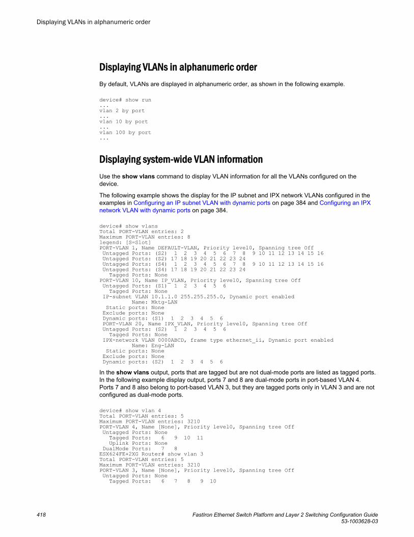
Displaying VLANs in alphanumeric orderBy default, VLANs are displayed in alphanumeric order, as shown in the following example.
device# show run...vlan 2 by port...vlan 10 by port...vlan 100 by port...
Displaying system-wide VLAN informationUse the show vlans command to display VLAN information for all the VLANs configured on thedevice.
The following example shows the display for the IP subnet and IPX network VLANs configured in theexamples in Configuring an IP subnet VLAN with dynamic ports on page 384 and Configuring an IPXnetwork VLAN with dynamic ports on page 384.
device# show vlansTotal PORT-VLAN entries: 2Maximum PORT-VLAN entries: 8legend: [S=Slot]PORT-VLAN 1, Name DEFAULT-VLAN, Priority level0, Spanning tree Off Untagged Ports: (S2) 1 2 3 4 5 6 7 8 9 10 11 12 13 14 15 16 Untagged Ports: (S2) 17 18 19 20 21 22 23 24 Untagged Ports: (S4) 1 2 3 4 5 6 7 8 9 10 11 12 13 14 15 16 Untagged Ports: (S4) 17 18 19 20 21 22 23 24 Tagged Ports: NonePORT-VLAN 10, Name IP_VLAN, Priority level0, Spanning tree Off Untagged Ports: (S1) 1 2 3 4 5 6 Tagged Ports: None IP-subnet VLAN 10.1.1.0 255.255.255.0, Dynamic port enabled Name: Mktg-LAN Static ports: None Exclude ports: None Dynamic ports: (S1) 1 2 3 4 5 6 PORT-VLAN 20, Name IPX_VLAN, Priority level0, Spanning tree Off Untagged Ports: (S2) 1 2 3 4 5 6 Tagged Ports: None IPX-network VLAN 0000ABCD, frame type ethernet_ii, Dynamic port enabled Name: Eng-LAN Static ports: None Exclude ports: None Dynamic ports: (S2) 1 2 3 4 5 6In the show vlans output, ports that are tagged but are not dual-mode ports are listed as tagged ports.In the following example display output, ports 7 and 8 are dual-mode ports in port-based VLAN 4.Ports 7 and 8 also belong to port-based VLAN 3, but they are tagged ports only in VLAN 3 and are notconfigured as dual-mode ports.
device# show vlan 4Total PORT-VLAN entries: 5Maximum PORT-VLAN entries: 3210PORT-VLAN 4, Name [None], Priority level0, Spanning tree Off Untagged Ports: None Tagged Ports: 6 9 10 11 Uplink Ports: None DualMode Ports: 7 8ESX624FE+2XG Router# show vlan 3Total PORT-VLAN entries: 5Maximum PORT-VLAN entries: 3210PORT-VLAN 3, Name [None], Priority level0, Spanning tree Off Untagged Ports: None Tagged Ports: 6 7 8 9 10
Displaying VLANs in alphanumeric order
418 FastIron Ethernet Switch Platform and Layer 2 Switching Configuration Guide53-1003628-03
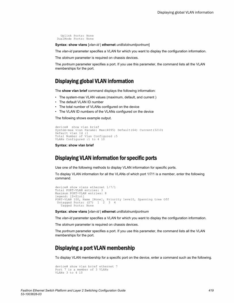
Uplink Ports: None DualMode Ports: NoneSyntax: show vlans [vlan-id | ethernet unit/slotnum/portnum]
The vlan-id parameter specifies a VLAN for which you want to display the configuration information.
The slotnum parameter is required on chassis devices.
The portnum parameter specifies a port. If you use this parameter, the command lists all the VLANmemberships for the port.
Displaying global VLAN informationThe show vlan brief command displays the following information:
• The system-max VLAN values (maximum, default, and current )• The default VLAN ID number• The total number of VLANs configured on the device• The VLAN ID numbers of the VLANs configured on the device
The following shows example output.
device# show vlan brief System-max vlan Params: Max(4095) Default(64) Current(3210)Default vlan Id :1Total Number of Vlan Configured :5VLANs Configured :1 to 4 10Syntax: show vlan brief
Displaying VLAN information for specific portsUse one of the following methods to display VLAN information for specific ports.
To display VLAN information for all the VLANs of which port 1/7/1 is a member, enter the followingcommand.
device# show vlans ethernet 1/7/1Total PORT-VLAN entries: 3Maximum PORT-VLAN entries: 8legend: [S=Slot]PORT-VLAN 100, Name [None], Priority level0, Spanning tree Off Untagged Ports: (S7) 1 2 3 4 Tagged Ports: NoneSyntax: show vlans [vlan-id | ethernet unit/slotnum/portnum
The vlan-id parameter specifies a VLAN for which you want to display the configuration information.
The slotnum parameter is required on chassis devices.
The portnum parameter specifies a port. If you use this parameter, the command lists all the VLANmemberships for the port.
Displaying a port VLAN membershipTo display VLAN membership for a specific port on the device, enter a command such as the following.
device# show vlan brief ethernet 7Port 7 is a member of 3 VLANsVLANs 3 to 4 10
Displaying global VLAN information
FastIron Ethernet Switch Platform and Layer 2 Switching Configuration Guide 41953-1003628-03
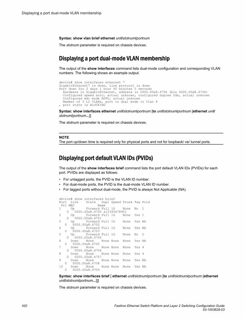
Syntax: show vlan brief ethernet unit/slotnum/portnum
The slotnum parameter is required on chassis devices.
Displaying a port dual-mode VLAN membershipThe output of the show interfaces command lists dual-mode configuration and corresponding VLANnumbers. The following shows an example output.
device# show interfaces ethernet 7GigabitEthernet7 is down, line protocol is downPort down for 2 days 1 hour 40 minutes 5 seconds Hardware is GigabitEthernet, address is 0000.00a8.4706 (bia 0000.00a8.4706) Configured speed auto, actual unknown, configured duplex fdx, actual unknown Configured mdi mode AUTO, actual unknown Member of 3 L2 VLANs, port is dual mode in Vlan 4, port state is BLOCKINGSyntax: show interfaces ethernet unit/slotnum/portnum [to unit/slotnum/portnum [ethernet unit/slotnum/portnum...]]
The slotnum parameter is required on chassis devices.
NOTEThe port up/down time is required only for physical ports and not for loopback/ ve/ tunnel ports.
Displaying port default VLAN IDs (PVIDs)The output of the show interfaces brief command lists the port default VLAN IDs (PVIDs) for eachport. PVIDs are displayed as follows:
• For untagged ports, the PVID is the VLAN ID number.• For dual-mode ports, the PVID is the dual-mode VLAN ID number.• For tagged ports without dual-mode, the PVID is always Not Applicable (NA).
device# show interfaces brief Port Link State Dupl Speed Trunk Tag Pvid Pri MAC Name1 Up Forward Full 1G None No 1 0 0000.00a8.4700 a123456789012 Up Forward Full 1G None Yes 1 0 0000.00a8.47013 Up Forward Full 1G None Yes NA 0 0000.00a8.47024 Up Forward Full 1G None Yes NA 0 0000.00a8.47035 Up Forward Full 1G None No 2 0 0000.00a8.47046 Down None None None None Yes NA 0 0000.00a8.47057 Down None None None None Yes 4 0 0000.00a8.47068 Down None None None None Yes 4 0 0000.00a8.47079 Down None None None None Yes NA 0 0000.00a8.470810 Down None None None None Yes NA 0 0000.00a8.4709Syntax: show interfaces brief [ ethernet unit/slotnum/portnum [to unit/slotnum/portnum [ethernetunit/slotnum/portnum...]]]
The slotnum parameter is required on chassis devices.
Displaying a port dual-mode VLAN membership
420 FastIron Ethernet Switch Platform and Layer 2 Switching Configuration Guide53-1003628-03
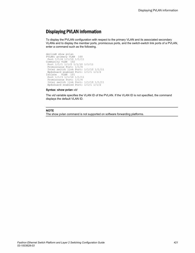
Displaying PVLAN informationTo display the PVLAN configuration with respect to the primary VLAN and its associated secondaryVLANs and to display the member ports, promiscous ports, and the switch-switch link ports of a PVLAN,enter a command such as the following.
device# show pvlanPVLAN: primary VLAN 100 Port 1/1/4 1/1/10 1/1/11Community VLAN 102 Port 1/1/1 1/1/2 1/1/10 1/1/11 Promiscuous Port: 1/1/4 Inter switch link Port: 1/1/10 1/1/11 BpduGuard enabled Port: 1/1/1 1/1/2 Isolate VLAN 101 Port 1/1/3 1/1/10 1/1/11 Promiscuous Port: 1/1/4 Inter switch link Port: 1/1/10 1/1/11 BpduGuard enabled Port: 1/1/1 1/1/2Syntax: show pvlan vid
The vid variable specifies the VLAN ID of the PVLAN. If the VLAN ID is not specified, the commanddisplays the default VLAN ID.
NOTEThe show pvlan command is not supported on software forwarding platforms.
Displaying PVLAN information
FastIron Ethernet Switch Platform and Layer 2 Switching Configuration Guide 42153-1003628-03

Displaying PVLAN information
422 FastIron Ethernet Switch Platform and Layer 2 Switching Configuration Guide53-1003628-03