Embed Size (px)
Citation preview
FastLink: An Efficient Initial Access Protocol for MillimeterWave Systems
Irmak Aykin
University of Arizona
Tucson, AZ
Marwan Krunz∗
University of Arizona
Tucson, AZ
ABSTRACTTo overcome the high propagation loss and satisfy a given link bud-
get, millimeter wave (mmW) communication systems rely on highly
directional antennas, both at the base station (BS) and the user
equipment (UE). Due to this directionality, initial access (IA) and
association can be particularly challenging. Existing approaches for
IA in directional networks suffer from long discovery time and/or
high misdetection probability of the UE. In this paper, we propose
FastLink, an efficient IA protocol for mmW systems with electroni-
cally steerable antennas. FastLink always transmits/receives using
the narrowest possible beam, allowing high beamforming gains
and low misdetection rate. It uses a unique binary-search-based
algorithm, called 3DPF, to scan only a small subset of the angular
space and find in logarithmic time the best transmit-receive beam
pair. We formulate the beam-finding process as a sparse problem,
exploiting the poor scattering nature of mmW channels. Compres-
sive sensing is then used to determine the minimum number of
measurements needed to reconstruct the sparse channel. 3DPF is
incorporated into FastLink to establish the directional link, and
the required messaging between the BS and the UE is explained
in detail. For performance evaluation purposes, we first conduct
simulations based on NYU mmW channel model and then experi-
ment with a custom mmW testbed utilizing uniform planar arrays
and operating at 29 GHz frequency. Our extensive simulations and
hardware experiments verify the efficiency of FastLink, and show
that 3DPF can reduce the search time by 65 − 99% compared to
802.11ad-like beam finding scheme.
KEYWORDSMillimeter wave, beam finding, initial access, directional communi-
cations, compressive sensing, analog beamforming.
ACM Reference Format:Irmak Aykin and Marwan Krunz. 2018. FastLink: An Efficient Initial Access
Protocol for Millimeter Wave Systems. In 21st ACM International Confer-ence on Modelling, Analysis and Simulation of Wireless and Mobile Systems(MSWIM ’18), October 28-November 2, 2018, Montreal, QC, Canada. ACM,
New York, NY, USA, 9 pages. https://doi.org/10.1145/3242102.3242105
∗Also with Dept. of EDE, University of Technology Sydney, Australia.
Permission to make digital or hard copies of all or part of this work for personal or
classroom use is granted without fee provided that copies are not made or distributed
for profit or commercial advantage and that copies bear this notice and the full citation
on the first page. Copyrights for components of this work owned by others than ACM
must be honored. Abstracting with credit is permitted. To copy otherwise, or republish,
to post on servers or to redistribute to lists, requires prior specific permission and/or a
fee. Request permissions from [email protected].
MSWIM ’18, Oct. 28-Nov. 2, 2018, Montreal, QC, Canada© 2018 Association for Computing Machinery.
ACM ISBN 978-1-4503-5960-3/18/10. . . $15.00
https://doi.org/10.1145/3242102.3242105
1 INTRODUCTIONThe abundant mmW spectrum is vital to meeting the high demands
of next-generation wireless technologies, including 5G cellular sys-
tems [1], WLANs (e.g., WiGig [16]), internet of things (IoT), and
connected and autonomous vehicles. However, extending wireless
communications to mmW bands faces many challenges, such as
high channel losses [6, 18], poor penetration through dry walls
and human body, and atmospheric absorption at certain mmW
frequencies [19]. These challenges limit signal coverage and hin-
der communications. On the other hand, due to the much smaller
wavelengths at mmW frequencies, many antenna elements can be
packed into a single device without increasing its form factor. With
proper processing of signals fed into these antennas, transmissions
can be beamed along a desired direction. The severe signal atten-
uation in the mmW bands can then be compensated for by the
beamforming gain obtained with the use of antenna arrays [4].
Depending on the beamforming architecture, the beamforming
weights that are used to focus the signal in a desired direction could
be applied in the digital and/or analog domain. Digital beamform-
ing multiplies a particular coefficient (i.e., beamforming weights)
by the modulated baseband signal of a given RF chain. Analog
beamforming, on the other hand, applies complex coefficients to
alter the RF signals by controlling phase shifters [20]. Finally, in hy-
brid (analog/digital) beamforming, the signal processing is divided
between the analog and digital domains, allowing a comparable
performance to digital beamforming but with fewer RF chains [12].
The high cost and power consumption of having multiple RF chains
force mmW systems to rely heavily on analog beamforming.
However, the increase in the spatial reuse due to highly direc-
tional communications comes at the cost of complicating various
control functions, including the initial access (IA) procedure [19].
IA allows a user equipment (UE) to establish a connection with a
base station (BS). In current 4G LTE systems, IA is performed in
an omnidirectional fashion, which alleviates the burden of beam
alignment. Beamforming or other directional transmissions can
be performed after initial link establishment. However, in mmW
frequencies, the IA procedure must be done directionally to allow
the UE to determine suitable initial directions for transmission. This
directional search delays the link establishment, lowers throughput
and reduces the bandwidth efficiency of mmW bands [13].
In this paper, we propose an efficient IA protocol called FastLink
for mmW systems. FastLink allows devices to transmit/receive us-
ing the narrowest possible beams, and hence providing the highest
possible beamforming gains. At the same time, the beam directions
are switched in such a way that BS/UE beam alignment can be
achieved in much shorter time compared to other search mech-
anisms used in the 802.11ad standard and 5G New Radio (NR).

MSWIM ’18, Oct. 28-Nov. 2, 2018, Montreal, QC, Canada Irmak Aykin and Marwan Krunz
FastLink aims at identifying the best transmit and receive beams in
an efficient way, exploiting channel sparsity. We first use compres-
sive sensing (CS) to determine the number of measurements (beam
probes) needed to find the “dominant” cluster. Then, using this
insight, we design a binary-search-based algorithm, called 3DPF, to
find the best transmit-receive beam pair in 3D. 3DPF divides the set
of beam directions into equally spaced subsets and then finds the
beam that achieves the maximum received power in each subset.
The number of subsets is a parameter that we determine using CS.
The contributions of this paper can be summarized as follows:
• Utilizing CS methods, we show how to obtain the optimal
beam direction using a small number of measurements that
is logarithmic in the total number of possible beams.
• We develop a novel 3D beam scanning algorithm, 3DPF,
based on beam subset partitioning and binary search, which
allows mmW devices to discover each other directionally
while keeping the discovery time and the UE misdetection
probability low.
• We integrate the proposed beam-finding algorithm into an
IA protocol, called FastLink, and we explain the required
control messages that need to be exchanged between the BS
and the UE.
• We verify the efficiency of 3DPF by conducting extensive
MATLAB simulations as well as hardware experiments on a
custom-built testbed. Our simulations implement the NYU
channel model [4] with modifications to account for more
realistic small scale effects. Our hardware setup is comprised
of a mmW signal generator, vector signal analyzer, and 4× 4
cross-cross polarized uniform planar arrays. We run the
experiments in the 29 GHz band, collecting the received
signal strength (RSS) measurements and timing results.
The experiments are conducted in an indoor office environment,
testing both line-of-sight (LOS) and non-line-of-sight (NLOS) con-
ditions. Our hardware experiments and simulation results indicate
that 3DPF reduces the search time by more than 65% compared to
802.11ad-like beam search, and yet achieves the same misdetection
probability.
2 RELATEDWORKFor mmW systems that rely on analog beamforming, three main
approaches for IA have been discussed in the literature: Exhaus-
tive search [1], two-stage hierarchical search [16], and context-
information-based (CI-based) search [3]. Exhaustive search is a
brute-force sequential beam searching technique that is proposed
for 5G NR [14]. In the 5G IA, the BS sequentially transmits synchro-
nization signals along different directions to allow undiscovered
UEs to detect one of the BS’s transmit beams [1]. This exhaus-
tive search comes at the cost of significant discovery time, as each
transmit/receive pair must be probed sequentially. On the other
hand, two-stage scanning used in the 802.11ad standard employs a
hierarchical multi-resolution beamforming codebook to expedite
IA. In the first phase, the access point (AP) sequentially transmits
synchronization signals over wider (quasi-omnidirectional) sectors
and tries to determine the best coarse direction. In the second phase
(beam refinement), the AP refines its search within the best coarse
sector by switching to narrow beams [16]. Although this approach
reduces the IA delay, the search time still scales linearly with the
number of narrow beams. Finally, in CI-based search, the UE simply
selects the optimal beam direction based on GPS information [13].
Alternative IA approaches to the above have been proposed in
the literature. The authors in [2] used a unique approach based on
hashing functions to identify the best beam. Although the hash
functions reduce the search time, the resulting beamforming gains
are lower than that of a single beam, leading to a higher misde-
tection probability. In [15], the authors proposed a beamforming
scheme that exploits the correlation between the sub-6 GHz and
the mmW interfaces to provide efficient beam alignment. Although
they improve the performance, their scheme requires a dedicated
sub-6 GHz channel, which may not be feasible for all mmW systems.
Finally, the authors in [22] proposed a model-driven beam-steering
scheme called OScan, which reduces the search latency. However,
their design is based on mmW channel measurements obtained
using horn antennas. In reality, horn antennas have significantly
different characteristics than phased-array antennas.
The aforementioned techniques present different tradeoffs be-
tween discovery time (time to establish directional communication
between the BS and the UE) andmisdetection probability. The misde-
tection probability is the probability that a UE is not being detected
by the BS. In its first phase, the 802.11ad scheme scans the space us-
ing wide beams, and thus achieves a low discovery time. However,
it also has a high chance of missing users due to low beamforming
gains. With the beam refinement phase (phase 2), 802.11ad scheme
attains better coverage and can even reach users located at the cell
edge, but this comes at the expense of much higher discovery time.
Recently, CS has gained great attention as a means to exploit
the sparsity of mmW channels [5, 11]. Essentially, CS is a signal
processing technique that can be used to efficiently reconstruct
a signal by solving an underdetermined set of linear equations.
It is based on the principle that signal sparsity can be exploited
to recover the signal using far fewer samples than required by
the Shannon-Nyquist sampling theorem [10]. This idea has been
applied in [5] for mmW channel estimation, where the authors
used it to design analog beamformers. Similarly, the authors in
[8] described a CS-based approach to estimate multipath channels
(not necessarily mmW) that have a sparse representation, without
imposing analog beamforming constraints. In [11], the authors also
utilized CS in a multiuser MIMO system to design beamformers in
a way that effectively mitigates interference. While these analyses
corroborate the significance of CS for channel estimation, they do
not specify a practical way for collecting the requiredmeasurements
and consider the algorithmic aspect of IA.
To obviate the shortcomings mentioned above, here we develop a
practical algorithm based on CS, which reduces the beam searching
delay while achieving a very lowmisdetection probability. Our algo-
rithm handles the IA completely in mmW bands. In addition, both
the analysis and the experiments utilize phased-array antennas,
which is the enabling technology for mmW communications.
3 BEAMFORMING IN ANTENNA ARRAYSWe consider the IA process between a BS and a single UE, with elec-
tronically steerable phased-array antennas at both ends. In addition,
we assume analog beamforming for both the BS and the UE, as it is
FastLink: An Efficient Initial Access Protocol for Millimeter Wave Systems MSWIM ’18, Oct. 28-Nov. 2, 2018, Montreal, QC, Canada
the most energy-efficient beamforming solution currently available.
Without loss of generality, we let the BS be the transmitter (Tx) and
UE be the receiver (Rx). In this section, we focus on the UE side
(Rx). Extension to the BS is straightforward. For simplicity, we do
not use subscripts to denote BS and UE.
Before we invoke on the algorithmic details of our IA design, we
first explain how phased-array antennas can be steered towards a
desired direction. To electronically steer the beam, complex weights
should be applied to each antenna element in the array. To deter-
mine these weights, we first calculate the array factors (AFs) of the
BS and UE antenna arrays. AF is the factor by which the element
factor of an individual antenna is multiplied to get the firing pattern
of the entire array. We start by analyzing a uniform linear array
(ULA) and then extend the analysis to a uniform planar array (UPA).
Let N and FULA
denote the number of antennas and the array
factor for a ULA, where the array receives a signal from a plane
wave at an incident angle θ (relative to the plane of the array).
Because the transmission paths are not equal, the received signal
has different phase shifts at different antenna elements. For a ULA,
adjacent elements are separated by the same distance d , leadingto a linear array of total length (N − 1)d . Note that the phase ofantenna element n leads the phase of element n − 1 by 2π
λ d cosθ ,where λ is the wavelength of the signal. Thus, we can write the
received signal at antenna n, n ∈ 1, · · · ,N , as:
sn = R In e jdn2πλ cos θ
(1)
where In is the amplitude excitation of the nth element and R is the
radiation pattern of each antenna element. As In does not affect
the analog beamforming weights, for simplicity, we assume In = 1.
Let the output of the antenna array, s , be a weighted sum of sn ’s,with each term sn multiplied by a complex weightwn :
s = RN∑n=1
wnejdn 2π
λ cos θ = R FULA. (2)
Assuming the same signal magnitude at each antenna, FULA
can be
maximized by selectingwn in a way to ensure that the received sig-
nals are in phase, i.e., by settingwn = e−jdn2πλ cos θ
. To achieve that,
the phase of the signal received by theN th antenna is kept the same,
and the phase of the signal received by every other antenna element
n, n = 1, · · · ,N − 1, is shifted by (N − n)γ = (N − n) 2πλ d cosθ .Now consider a UPA with a horizontal inter-element distance
dx , vertical inter-element distance dy , and the AF denoted as FUPA
.
Suppose that the incident wave of the received signal arrives from
polar angle θ and azimuth angle α , and the antennas are placed on
anM × N 2D grid. Following a similar analysis, we can write the
received signal at antenna element (m,n), sm,n as:
sm,n = R e j2πλ (dxm cosα sin θ+dyn sinα sin θ )
(3)
wherem ∈ 1, · · · ,M and n ∈ 1, · · · ,N . Similarly, the received
signal s after beamforming with complex phase-shift weightswm,ncan be written as:
s = RM∑
m=1
N∑n=1
wm,nej 2πλ (dxm cosα sin θ+dyn sinα sin θ ) = R F
UPA(4)
Complex beamformer weights can then be calculated as wm,n =
e−j2πλ (dxm cosα sin θ+dyn sinα sin θ )
.
4 CS-BASED BEAM FINDINGBecause of the few reflections in mmW communications, the chan-
nel matrix between the BS and the UE is sparse [4, 7]. More specifi-
cally, a transmitted signal reaches the Rx along a few AoA clusters,
depending on the environment (see for example, the received power
profile in Fig. 5 in Section 7.1). CS has been widely used in the liter-
ature to capture and represent sparse signals at a rate significantly
below the Nyquist rate [5, 10]. Considering the limited scattering
nature of the mmW channel, in this section, we formulate the chan-
nel estimation problem as a sparse problem. We then show how CS
can be used to find the optimal beam direction.
First, we express the channel between a BS and a UE under UPAs.
To denote a matrix of x rows and y columns, we use the notation
x × y. Let the total number of antennas at the BS and the UE be
ABS= M
BSN
BSand A
UE= M
UEN
UE, respectively. Here, Mi and Ni ,
i ∈ BS,UE, refer to the number of rows and columns in the UPA.
Let aB (θ ′p ,α′p ) denote theABS
×1 array response vector (ARV) of the
BS antenna system and aU (θp ,αp ) denote theAUE×1ARV of the UE
antenna system for a given cluster p. Here, (θp ,αp ) and (θ′p ,α′p ) are
the AoA and angle-of-departure (AoD) for cluster p, at the time of
reception or transmission, respectively. Then, theAUE×A
BSchannel
matrix H between the BS and the UE can be expressed as:
H =P∑p=1
hpaU (θp ,αp )a∗B (θ′p ,α′p ) (5)
where (.)∗ denotes conjugate transpose operation, P is the number
of clusters, and hp is the gain of the pth cluster (a complex number).
The transmit and receive beamforming vectors for any desired
direction can be computed offline and stored in codebooks at the
Tx and the Rx. At any time during IA, when the BS is using a
transmit beamforming vector fi ∈ CABS×1and UE is using a receive
beamforming vector qj ∈ CAUE×1(i and j are the indices of the
beamforming vectors in their codebooks), we can represent the
received signal yi j as:
yi j = q∗j Hfis + q∗j n (6)
where s is the transmitted signal and n ∈ CAUE×1is a matrix
whose entries are complex circularly-symmetric white Gaussian
noise. Note that a given Tx beamformer fi (also, a given Rx beam-
former qj ) specifies the values for the angles α and θ in the Tx
(also, Rx) antenna weight wm,n , computed in Section 3. Let Q =q1, q2, · · · , qD denote the codebook of the Rx beamformer, where
D is the maximum number of narrow beams that can be generated
at the Rx (depends on the resolution of the phase shifters).
To find the optimal Rx beamformer for a given Tx beamformer,
we define the precoded channel vector gi , Hfi , where gi ∈CAUE×1
. Then, q∗j gi corresponds to measuring gi with the Rx beam
j. Using the codebook Q, we can form a basis matrix Q whose jthrow is given by q∗j , j = 1, · · · ,D. Then, D measurements for D
different Rx beamformers and a given precoded channel gi can be
collected as v = Qgi , where v is a vector of length D, containingthe channel measurement results. Our aim here is to reconstruct
v by taking only r measurements from gm where r < D, and find
the beam IDs of these r measurements. From (5), the channel has P
MSWIM ’18, Oct. 28-Nov. 2, 2018, Montreal, QC, Canada Irmak Aykin and Marwan Krunz
clusters, meaning that v is P-sparse, i.e., it displays P peak values1.
Hence, v can be constructed provided that r ≥ P . Let us define Φas an r × D compressed measurement matrix. Then, output Ψ of
the compressed measurement process can be represented as:
Ψ = Φv = ΦQgi = Θgi (7)
where Θ is an r × AUEmatrix and Ψ is a column vector of length
r . The problem is then reduced to designing a stable measurement
matrix Φ such that the key information in any P-sparse or com-
pressible signal is not lost through the dimensionality reduction. In
other words, we would like to reconstruct v by using the available
measurement results Ψ and the known compressed measurement
matrix Φ. A necessary and sufficient condition to find a solution to
our problem for the P-sparse v is the restricted isometry property
(RIP), which is satisfied by a given matrix Θ if [10]
(1 − ϵ) ≤∥Θz∥2
2
∥z∥22
≤ (1 + ϵ) (8)
holds for any arbitrary P-sparse z and for some isometry constant
ϵ > 0. Specifically, the matrix Θ must preserve the length of an
arbitrary P-sparse z. A related condition, referred to as incoherence,requires that the rows of Φ to not sparsely represent the columns
of Q. Both the RIP and incoherence can be achieved with high prob-
ability simply by selecting Φ as a random matrix [10]. Specifically,
when the entries of Φ are drawn independently from a N(0, 1/r )distribution, Φ can satisfy RIP and incoherence with high probabil-
ity if r ≥ cP log(D/P), where c is a small constant that depends on
the desired probability of success. This result is summarized in the
following theorem [10]:
Theorem 1. Let r ≥ cP log(D/P) and construct Φ by drawing itsentries independently from a Gaussian distribution N(0, 1/r ). Then,with probability exceeding 1 − e−cr , it is possible to reconstruct everyP-sparse signal v of length D using Ψ.
Thus, the P-sparse v can be recovered from only r ≥ cP log(D/P)random measurements. Generally, Φ is constructed iteratively by
adding a new random row at each iteration. However, the mea-
surement matrix Φ constructed with random phase shifts has low
beamforming gains, which will likely not satisfy the link budget
[21]. On the other hand, by selecting the rows of Φ from the code-
book Q, the beamforming gains for any given direction can be
maximized. To find which beamformers to select from Q, Bayesiancompressive sensing can be used [17]. With this approach, Φ can
be constructed such that at each iteration, a new row is selected
from Q with the goal of reducing the uncertainty in the estimated
v. In step n, this is equivalent to selecting a row that maximizes the
variance of the measurement resultψn , whereψn denotes the nthelement of Ψ. In other words, the new row q∗i should be selected toconstitute the measurement for which the data is most uncertain.
Using this, we next describe three algorithms that aim at deter-
mining the best beam directions for the BS and the UE. Because
closeby beams give correlated results (and hence cannot maximize
the variance of a new measurement), in each iteration, the algo-
rithms probe a beam that points at a significantly different angle.
1In general, the notion of P -sparsity is used for vectors with at most P nonzero entries.
However, as shown in [9], compressive sensing can be used to reconstruct noisy vectors
with P peaks. Therefore, for convenience, we refer to vectors exhibiting P peaks as
P -sparse.
5 PEAK-FINDING ALGORITHMSIn this section, we first develop two algorithms for 2D beam finding,
and then we extend these algorithms to a 3D environment. The
algorithms seek to identify the Rx beam j that yields the largest|q∗j gi |
2, i.e, the largest gain for a given precoded channel. In Sec-
tion 5.1, we design an algorithm to find the best beam in the case
of a single cluster. We extend this design to multiple clusters in
Section 5.2. In Section 5.3, we modify the algorithms to work in a
3D environment. Finally, in Section 5.4, we discuss how to select
the optimal design parameter K (number of angular regions).
5.1 Single-peak Finding (SPF) AlgorithmFor now, we assume that the Tx is pointing towards a fixed, arbitrar-
ily chosen direction using its beam i and beamformer fi . Rx triesto find the optimal beam w.r.t the given Tx direction. Extension
to finding the optimal direction in the Tx side will be explained
in Section 6. While pointing in a given direction i , the Tx sends
synchronization signals and Rx measures the received power by
steering its receive beam. For brevity, in this section, we omit the
subscript i from gi . Note that for now, we consider a fixed elevationangle for both Tx and the Rx, and aim at finding the best azimuth
angle for the Rx.
A typical plot of beam ID vs. SNR displays multiple peaks due
to channel clusters. For now, we consider a single-peak scenario
(see Fig. 1). Note that the graph in Fig. 1 cannot be perfectly recon-
structed without measuring the SNR for each Rx beam. However,
our aim is to find the peak by using only a subset of Rx beams,
exploiting the previously presented CS analysis. Specifically, we
aim at taking r measurements (r < D) such that the optimal Rx
beamformer for a given Tx beamformer can be found with high
probability (see Thm. 1).
Our proposed algorithm, called SPF, is a variation of binary
search. First, the precoded channel g is measured using an Rx beam-
former qi that generates a starting beam i in the middle of the
Rx field-of-view (FoV). From qi , we obtain vi = q∗i g. Then, i’s leftand right adjacent beams in the azimuth domain, i − 1 and i + 1,are scanned and vi−1 = q∗i−1g and vi+1 = q∗i+1g are obtained. If
|vi |2 > |vi−1 |
2and |vi |
2 > |vi+1 |2, where | · | indicates the modulus
of a complex number, then vi is the peak. Otherwise, v is “rising"
towards the left or the right of beam i . Thus, the directions that vis not rising towards no longer need to be scanned. This leaves us
with the subset of the codebook Q′
, where Q′
= Q1, · · · , i − 1 orQ′
= Qi + 1, · · · ,D, eliminating the need to probe the directions
in Q/Q′
∪ i. Then, the procedure is repeated for the remaining
directions in Q′
until the peak is reached (see Algorithm 1). An
example is illustrated in Fig. 1, where the numbers below the dots
represent the order by which the beams are scanned.
If v exhibits a single peak, the SPF algorithm finds it in O(logD)time. However, if v has multiple peaks, SPF finds only one of the
peaks, and not necessarily the optimal. To cope with that, we next
propose the multiple-peak finding (MPF) algorithm.
5.2 Multiple-peak Finding (MPF) AlgorithmTo reduce the chances of getting stuck at a local maximum, in
the MPF algorithm, the codebook Q is divided into K equal-size
subsets, each representing an angular region. Here, K is selected
FastLink: An Efficient Initial Access Protocol for Millimeter Wave Systems MSWIM ’18, Oct. 28-Nov. 2, 2018, Montreal, QC, Canada
Algorithm 1 Single-peak Finding Algorithm
1: procedure Single_Peak(Q, g)2: Initialize:3: i ← D/24: vi ← q∗i g, vi−1 ← q∗i−1g, vi+1 ← q∗i+1g5: Recursion:6: if |vi |2 > |vi−1 |2 and |vi |2 > |vi+1 |2 then return |vi |2
7: else if |vi |2 > |vi−1 |2 and |vi |2 < |vi+1 |2 then returnSINGLE_PEAK(Qi + 1 : D, g)
8: else return SINGLE_PEAK(Q1 : i − 1, g)
Beam ID
Re
ceiv
ed
Po
we
r
(3) (1)
(2)(4)
1 2 3 4 5 6 7 8 9 10 11 12 13
Figure 1: Received power vs. beam ID (single peak). Num-bers below the dots represent the order by which the beamsare scanned. Red dots correspond to intermediate beams andthe green dot corresponds to the peak.
Algorithm 2Multi-peak Finding Algorithm
1: procedure Multi_Peak(Q, g, K )2: Divide Regions:3: Divide Q into K equal regions Ri4: Finding Peaks:5: Candidates Ω ← 6: for Each Ri , i ∈ 1, · · ·K do7: localMax← SINGLE_PEAK(Ri , g)8: Ω ← Ω∪ localMax
return max(Ω)
in a way that each region is likely to contain at most one peak.
Then, the SPF algorithm runs within each region. Finally, the local
maxima that are found at different regions are compared, and the
largest among them is selected (see Algorithm 2). The complexity
is O(K logDK ), as the SPF algorithm is run in K regions, each of
sizeDK . Clearly, as K approaches D, the MPF algorithm converges
to exhaustive search and the complexity approaches O(D). On the
other hand, if K is chosen very small (e.g., 1), the complexity is
O(logD), but there is a high chance that the global maximum will
be missed. If the local maxima that the algorithm returns cannot
support the link budget, a misdetection is declared; otherwise the
beam is declared “suboptimal” but communications along that beam
can still be established. Thus, by choosing a proper K , we increasethe chances of having at most one peak in each region, which the
algorithm is guaranteed to find.
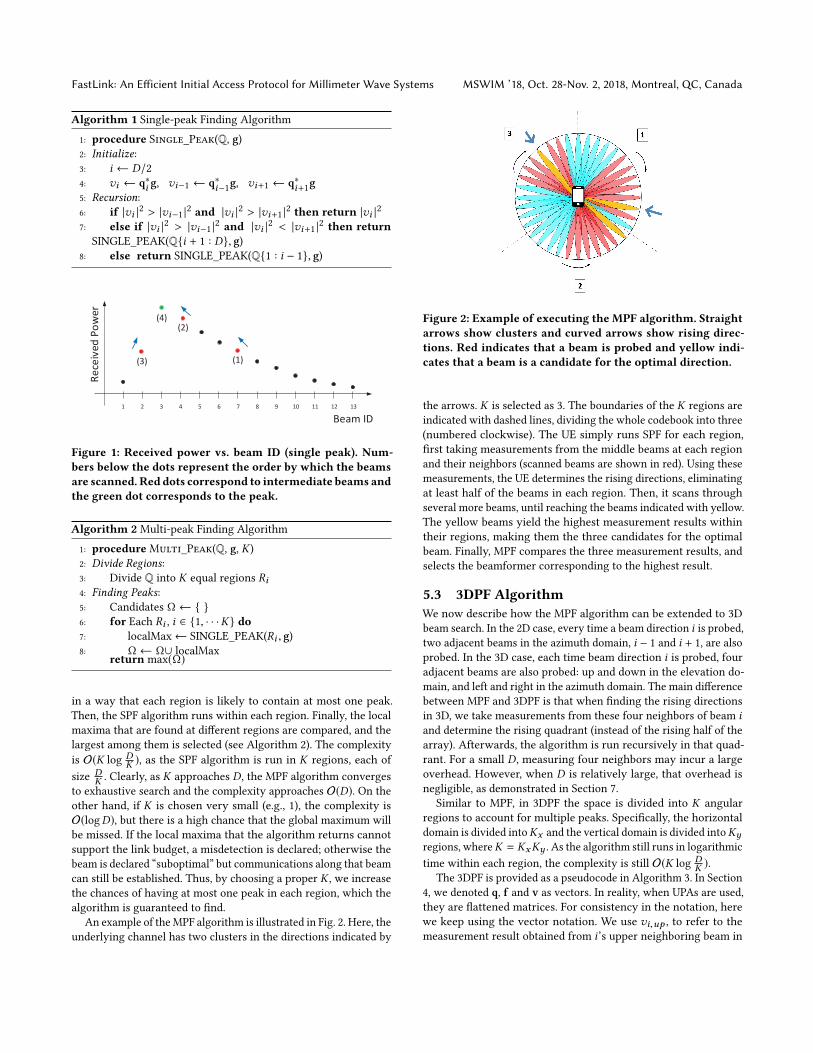
An example of theMPF algorithm is illustrated in Fig. 2. Here, the
underlying channel has two clusters in the directions indicated by
Figure 2: Example of executing the MPF algorithm. Straightarrows show clusters and curved arrows show rising direc-tions. Red indicates that a beam is probed and yellow indi-cates that a beam is a candidate for the optimal direction.
the arrows. K is selected as 3. The boundaries of the K regions are
indicated with dashed lines, dividing the whole codebook into three
(numbered clockwise). The UE simply runs SPF for each region,
first taking measurements from the middle beams at each region
and their neighbors (scanned beams are shown in red). Using these
measurements, the UE determines the rising directions, eliminating
at least half of the beams in each region. Then, it scans through
several more beams, until reaching the beams indicated with yellow.
The yellow beams yield the highest measurement results within
their regions, making them the three candidates for the optimal
beam. Finally, MPF compares the three measurement results, and
selects the beamformer corresponding to the highest result.
5.3 3DPF AlgorithmWe now describe how the MPF algorithm can be extended to 3D
beam search. In the 2D case, every time a beam direction i is probed,two adjacent beams in the azimuth domain, i − 1 and i + 1, are alsoprobed. In the 3D case, each time beam direction i is probed, fouradjacent beams are also probed: up and down in the elevation do-
main, and left and right in the azimuth domain. The main difference
between MPF and 3DPF is that when finding the rising directions
in 3D, we take measurements from these four neighbors of beam iand determine the rising quadrant (instead of the rising half of the
array). Afterwards, the algorithm is run recursively in that quad-
rant. For a small D, measuring four neighbors may incur a large
overhead. However, when D is relatively large, that overhead is
negligible, as demonstrated in Section 7.
Similar to MPF, in 3DPF the space is divided into K angular
regions to account for multiple peaks. Specifically, the horizontal
domain is divided intoKx and the vertical domain is divided intoKyregions, whereK = KxKy . As the algorithm still runs in logarithmic
time within each region, the complexity is still O(K logDK ).
The 3DPF is provided as a pseudocode in Algorithm 3. In Section
4, we denoted q, f and v as vectors. In reality, when UPAs are used,
they are flattened matrices. For consistency in the notation, here
we keep using the vector notation. We use vi,up , to refer to the
measurement result obtained from i’s upper neighboring beam in
MSWIM ’18, Oct. 28-Nov. 2, 2018, Montreal, QC, Canada Irmak Aykin and Marwan Krunz
Algorithm 3 3DPF Algorithm
1: procedure 3D_Single_Peak(Q, g)2: Initialize:3: i ← middle beam of Q4: vi ← q∗i g5: vi,lef t ← q∗i,lef t g, vi,r iдht ← q∗i,r iдht g6: vi,up ← q∗i,upg, vi,down ← q∗i,downg7: Recursion:8: if |vi |2 > |vi,up |2 and |vi |2 > |vi,down |
2 and |vi |2 >|vi,lef t |
2 and |vi |2 > |vi,r iдht |2 then return |vi |2
9: else if |vi |2 < |vi,up |2 and |vi |2 < |vi,r iдht |2 then re-turn 3D_Single_Peak(Qupper-right quadrant, g)
10: else if |vi |2 < |vi,up |2 and |vi |2 < |vi,lef t |2 then return3D_Single_Peak(Qupper-left quadrant, g)
11: else if |vi |2 < |vi,down |2 and |vi |2 < |vi,r iдht |2 then
return 3D_Single_Peak(Qlower-right quadrant, g)12: else return 3D_Single_Peak(Qlower-left quadrant, g)13: procedure 3DPF(Q, g, Kx , Ky )14: Divide Regions:15: Divide Q into K (K = KxKy ) equal regions Ri16: Finding Peaks:17: Candidates Ω ← 18: for Each Ri , i ∈ 1, · · ·K do19: localMax← 3D_SINGLE_PEAK(Ri , g)20: Ω ← Ω∪ localMax
return max(Ω)
the elevation domain. Similar definitions apply to vi,lef t , vi,r iдht ,and vi,down . The notation for qi is extended the same way to
account for four different neighboring beam directions.
5.4 Selecting the Optimal Number of RegionsAs discussed in Section 4, the peaks of the P-sparse measurement
vector v can be found with high probability using r ≥ cP log(D/P)samples (probed narrow beams). Setting K = P in the 3DPF algo-
rithm yields r = P logDP samples. As a result, for r to be greater
than or equal to cP log(D/P), c must be equal to 1. Using Theorem 1,
it is proven that with K = P , the 3DPF algorithm has a misdetection
probability below e−cr = e−r .Unfortunately, there is no way to know in advance how many
clusters a given environment exhibits at a specific operating fre-
quency. However, there exists several works addressing the dis-
tribution of the number of clusters in various mmW bands (e.g.,
[4, 16]). In this paper, we aim at accounting for a relatively large
number of clusters to lower the chances of misdetection. Let P∗
be the 95th-percentile of P . In [4], P is modeled as a random vari-
able with distribution maxPoisson(µ), 1, where µ = 1.8, for the
28 GHz band. Solving numerically, P∗ ≈ 3.72 when the operating
frequency is 28 GHz. We can then select K = ⌈P∗⌉, where ⌈.⌉ is theceiling function. Note that in [4], P is modeled for a 2D channel. In
our experiments, we observed that for 2D beam searching, select-
ing K = 4 achieves good performance in terms of discovery time
and misdetection probability. For 3DPF, we tried several K values
and found K = 16 to achieve very low misdetection rate and high
probability of identifying the optimal beam.
6 FASTLINK PROTOCOLIn this section, we present our FastLink protocol for the IA process
in mmW systems, and explain how it integrates the 3DPF algorithm
as part of the message exchange between the BS and the UE.
In LTE systems, the IA procedure utilizes an omnidirectional
signal called the Cell Reference Signal (CRS), which is regularly
monitored by each UE to create a wideband channel estimate that
can be used both for demodulating DL transmissions and for esti-
mating the channel quality [14]. However, for 5G mmW systems,
IA must take place directionally. As a result, when the main beams
of the Tx and the Rx do not point to each other, the directional link
cannot be established.
To find a suitable directional link, recent 5G specifications re-
quire that the BS covers the whole spatial area with a pre-configured
number of beams, using periodically transmitted synchronization
signal (SS) blocks [1]. These SS blocks carry primary synchroniza-
tion signals (PSS), secondary synchronization signals (SSS), and
physical broadcast channel (PBCH) information. PSS is mainly used
for initial symbol boundary synchronization to the NR cell and the
SSS is used for detection of cell and beam IDs. When the UE enters
the coverage area of a BS, it listens to an SS burst (consisting of
multiple SS blocks) and measures the signal quality of different
beams. It then determines the beam for which the received power
is maximum (and above a predefined threshold). This beam will be
chosen for subsequent transmissions/receptions. After determining
the best BS beam, the UE has to wait for the BS to schedule the
random access channel (RACH) opportunity for the beam direction
that the UE has selected. For each SS block, the BS will specify one
or more RACH opportunities to occur in a certain time, frequency,
and direction, so that the UE knows when to transmit the RACH
preamble [14]. During a RACH opportunity, UE performs random
access, implicitly informing the BS of its selected beam direction.
Note that the existing 5G specifications do not standardize how
beam sweeping will be performed at the UE.
Our 3DPF algorithm can be directly applied at the UE side, with-
out changing the default 5G IA process. This reduces the search
time at the UE side, but the BS still sweeps its beams exhaustively.
With some small changes in the IA structure, 3DPF can be employed
at both the BS and the UE. In FastLink, the BS and the UE both se-
quentially scan a small subset of their beam directions. Specifically,
during an SS block, the BS steers its beam towards a direction and
transmits PSS and SSS. During this SS block, the UE constantly mea-
sures the received power, steering its receive beam according to the
3DPF algorithm. At the end of the SS block, the BS switches to Rx
mode, and listens to a REPLY message from the UE along the same
beam direction. UE sends its REPLY using the best beam direction
it found for the given BS beam. After measuring the Rx power, in
the next SS block, the BS steers its beam towards another direction
suggested by 3DPF, and the UE runs a new search for the new BS
beam. Measurements of received powers of REPLY messages are
stored in a table at the BS. In the last stage of 3DPF, BS selects the
beam with the highest power.
For a time division duplex (TDD) system, the BS and UE operate
on the same frequency, and so the number of clusters they experi-
ence are the same. Thus, the optimal K for the BS and the UE are
the same, i.e. KBS= K
UE= ⌈P∗⌉, as discussed in Section 5.4. This
FastLink: An Efficient Initial Access Protocol for Millimeter Wave Systems MSWIM ’18, Oct. 28-Nov. 2, 2018, Montreal, QC, Canada
Data transmission
UE beam training
...1 τUE UE
BS beam i ... BS beam j
2
REPLYSS block
Figure 3: Proposed transmission block structure.
allows the BS to know how long each SS block should last (for UE
to run 3DPF), without prior communication with the UE.
The transmission block structure for FastLink is shown in Fig.
3. BS sends PSS and SSS for τUEconsecutive mini-slots within an
SS block through a selected beam i , where τUE
is the maximum
required number of mini-slots for the UE to run 3DPF algorithm
with the pre-selected K . Specifically, τUE= ⌈P∗⌉ log DUE
⌈P ∗ ⌉ , where
DUE
is the maximum number of narrow beams at the UE. Then,
the UE determines the best receive beam for BS transmit beam iand sends a REPLY message to the BS. However, the power of the
signal received by the BS can be lower than its sensitivity. If the
BS does not receive a REPLY message from the UE after τUEmini-
slots, it stores a minimum power value, ζ , in its table for beam i .Then, the BS continues executing 3DPF, selecting the next transmit
beam suggested by the algorithm according to the received power
value. In total, BS needs to scan at most τBS= ⌈P∗⌉ log DBS
⌈P ∗ ⌉ beams,
where DBSis the maximum number of narrow beams at the BS.
After collecting all REPLY messages from the UE for the selected
beams, the BS finally selects the best transmit beam from the table
and the UE selects the best receive beam for the given transmit
beam. This way, the time required to establish a directional link
can be reduced from DBSD
UEto τ
BSτUE(τ
BS≪ D
BSand τ
UE≪ D
UE).
7 PERFORMANCE EVALUATIONIn this section, we evaluate the performance of 3DPF through exten-
sive hardware experiments and computer simulations. We compare
3DPF with 802.11ad beam search approach, in which the search
time scales linearly with D. Note that current 5G NR beam search
also scales linearly with D, attaining similar results to 802.11ad.
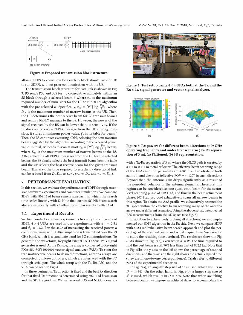
7.1 Experimental ResultsWe first conduct extensive experiments to verify the efficiency of
3DPF. 4 × 4 UPAs are used in our experiments with dx = 0.5λand dy = 0.6λ. For the sake of measuring the received power, a
continuous wave with 5 dBm amplitude is transmitted over the 29
GHz band, which is a candidate band for 5G communications. To
generate the waveform, Keysight E8257D-ATO-8384 PSG signal
generator is used. At the Rx side, the array is connected to Keysight
PXA-550-MY55002004 vector signal analyzer (VSA). To steer the
transmit/receive beams to desired directions, antenna arrays are
connected to microcontrollers, which are interfaced with the PC
through serial port. The whole setup with the Tx, Rx, PSG, and the
VSA can be seen in Fig. 4.
In the experiments, Tx direction is fixed and the best Rx direction
for that fixed Tx direction is determined using 802.11ad beam scan
and the 3DPF algorithm. We test several LOS and NLOS scenarios
Figure 4: Test setup using 4 × 4 UPAs both at the Tx and theRx side, signal generator and vector signal analyzer.
-60
-40
-20
0
20
40
60
Azi
mut
h A
ngle
s (d
egre
es)
-60-40-200 20 40 60
Elevation Angles (degrees)
-90
-85
-80
-75
-70
-65
-60
-55
(a)
-100
60 60
-80
40 40 20
Azimuth Angles
20
Rec
eive
d P
ower
(dB
m)
Elevation Angles
0 0
-60
-20-20-40-40
-60-60
-40
(b)
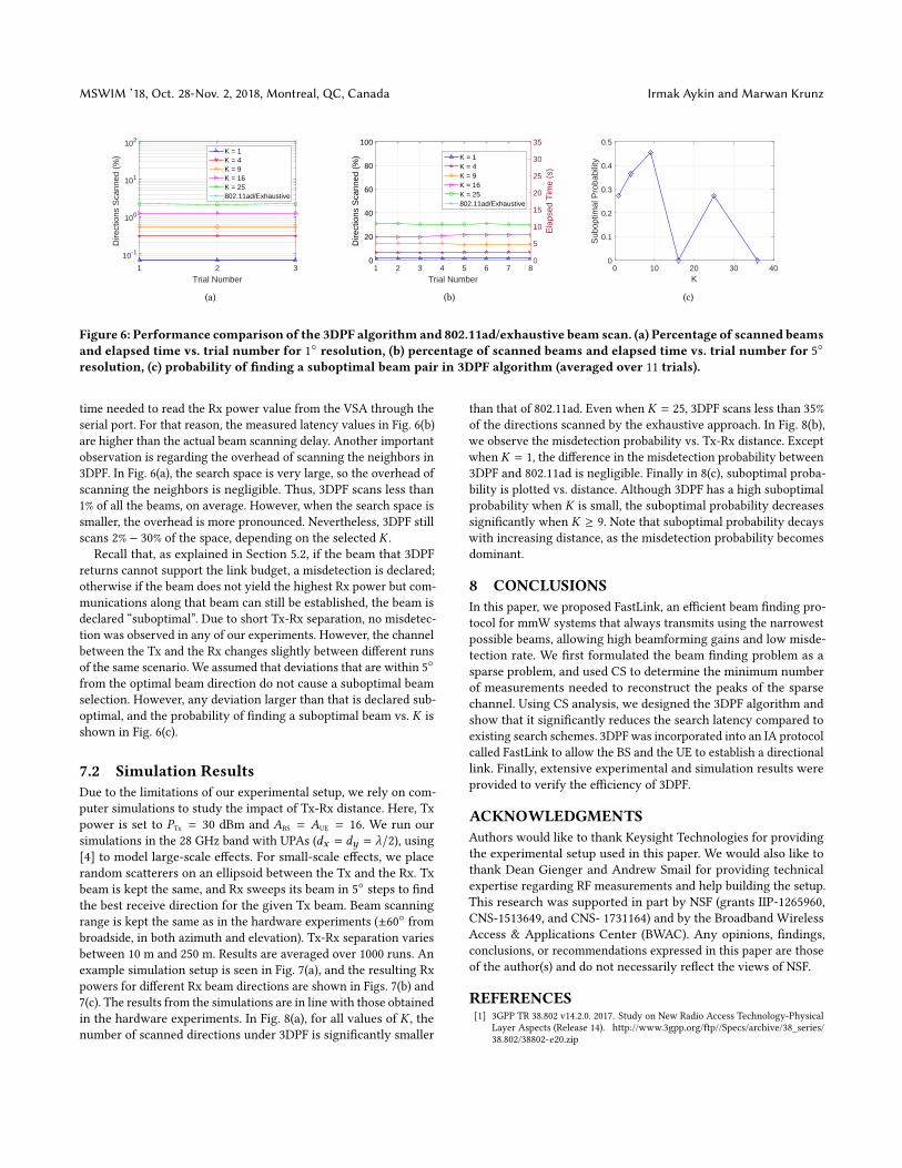
Figure 5: Rx powers for different beam directions at 29 GHzoperating frequency and under first scenario (Tx-Rx separa-tion of 3m). (a) Flattened, (b) 3D representation.
with a Tx-Rx separation of 3 m, where the NLOS path is created by
a 1.2 m × 1.2 m metal reflector. The effective beam scanning range
of the UPAs in our experiments are ±60 from broadside, in both
azimuth and elevation (effective FOV = ∼ 120in each direction).
Beyond that, the antenna gain drops significantly as a result of
the non-ideal behavior of the antenna elements. Therefore, this
region can be considered as one quasi-omni beam for the sector-
level scanning phase of 802.11ad, and thus in the beam refinement
phase, 802.11ad protocol exhaustively scans all narrow beams in
this region. To obtain the AoA profile, we exhaustively scanned the
3D space within the effective beam scanning range of the antenna
arrays under different scenarios. Using the above setup, we collected
RSS measurements from the 3D space (see Fig. 5).
In addition to exhaustively probing all directions, we also imple-
mented our 3DPF algorithm in the Rx side. Next, we compare 3DPF
with 802.11ad/exhaustive beam search approach and plot the per-
centage of the scanned beams and actual elapsed time. We varied Kto study the resulting time overhead. The results are shown in Fig.
6. As shown in Fig. 6(b), even when K = 25, the time required to
find the best beam is still 70% less than that of 802.11ad. Note that
in Fig. 6(b), the y-axis on the left shows the percentage of scanned
directions, and the y-axis on the right shows the actual elapsed time
(they are in one-to-one correspondence). Trials refer to different
runs of the experimental scenarios.
In Fig. 6(a), an angular step size of 1is used, which results in
D = 14641. On the other hand, in Fig. 6(b), a larger step size of
5is used, which results in D = 625. Note that when switching
between beams, we impose an artificial delay to accommodate the
MSWIM ’18, Oct. 28-Nov. 2, 2018, Montreal, QC, Canada Irmak Aykin and Marwan Krunz
1 2 3
Trial Number
10-1
100
101
102
Dire
ctio
ns S
cann
ed (
%)
K = 1K = 4K = 9K = 16K = 25802.11ad/Exhaustive
(a)
1 2 3 4 5 6 7 8
Trial Number
0
20
40
60
80
100
Dire
ctio
ns S
cann
ed (
%)
0
5
10
15
20
25
30
35
Ela
psed
Tim
e (s
)
K = 1K = 4K = 9K = 16K = 25802.11ad/Exhaustive
(b)
0 10 20 30 40K
0
0.1
0.2
0.3
0.4
0.5
Sub
optim
al P
roba
bilit
y
(c)
Figure 6: Performance comparison of the 3DPF algorithm and 802.11ad/exhaustive beam scan. (a) Percentage of scanned beamsand elapsed time vs. trial number for 1 resolution, (b) percentage of scanned beams and elapsed time vs. trial number for 5
resolution, (c) probability of finding a suboptimal beam pair in 3DPF algorithm (averaged over 11 trials).
time needed to read the Rx power value from the VSA through the
serial port. For that reason, the measured latency values in Fig. 6(b)
are higher than the actual beam scanning delay. Another important
observation is regarding the overhead of scanning the neighbors in
3DPF. In Fig. 6(a), the search space is very large, so the overhead of
scanning the neighbors is negligible. Thus, 3DPF scans less than
1% of all the beams, on average. However, when the search space is
smaller, the overhead is more pronounced. Nevertheless, 3DPF still
scans 2% − 30% of the space, depending on the selected K .Recall that, as explained in Section 5.2, if the beam that 3DPF
returns cannot support the link budget, a misdetection is declared;
otherwise if the beam does not yield the highest Rx power but com-
munications along that beam can still be established, the beam is
declared “suboptimal”. Due to short Tx-Rx separation, no misdetec-
tion was observed in any of our experiments. However, the channel
between the Tx and the Rx changes slightly between different runs
of the same scenario. We assumed that deviations that are within 5
from the optimal beam direction do not cause a suboptimal beam
selection. However, any deviation larger than that is declared sub-
optimal, and the probability of finding a suboptimal beam vs. K is
shown in Fig. 6(c).
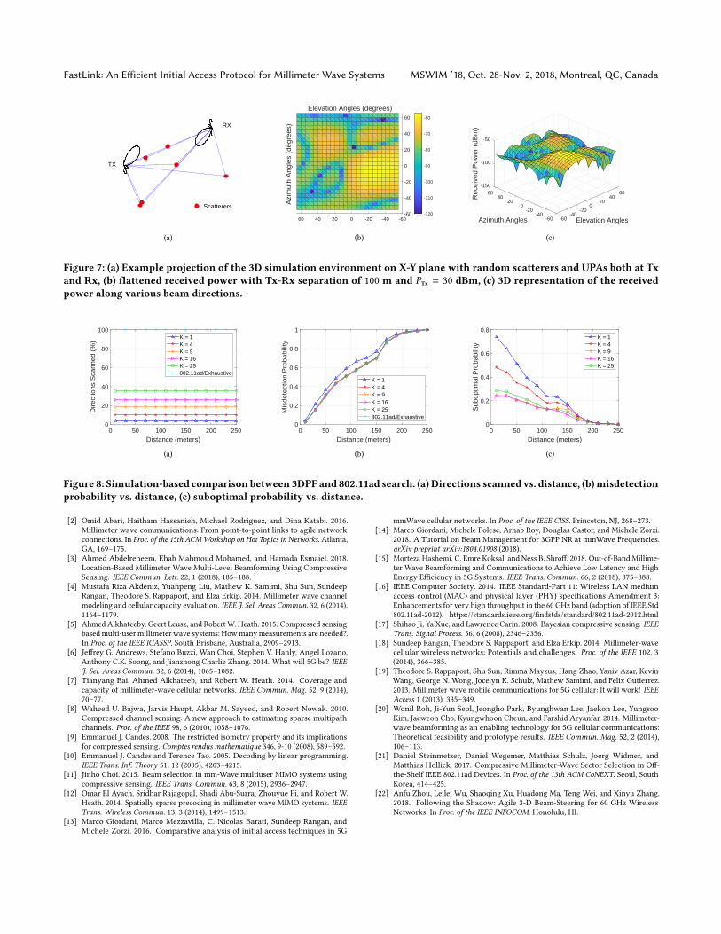
7.2 Simulation ResultsDue to the limitations of our experimental setup, we rely on com-
puter simulations to study the impact of Tx-Rx distance. Here, Tx
power is set to PTx= 30 dBm and A
BS= A
UE= 16. We run our
simulations in the 28 GHz band with UPAs (dx = dy = λ/2), using[4] to model large-scale effects. For small-scale effects, we place
random scatterers on an ellipsoid between the Tx and the Rx. Tx
beam is kept the same, and Rx sweeps its beam in 5steps to find
the best receive direction for the given Tx beam. Beam scanning
range is kept the same as in the hardware experiments (±60 from
broadside, in both azimuth and elevation). Tx-Rx separation varies
between 10 m and 250 m. Results are averaged over 1000 runs. An
example simulation setup is seen in Fig. 7(a), and the resulting Rx
powers for different Rx beam directions are shown in Figs. 7(b) and
7(c). The results from the simulations are in line with those obtained
in the hardware experiments. In Fig. 8(a), for all values of K , thenumber of scanned directions under 3DPF is significantly smaller
than that of 802.11ad. Even when K = 25, 3DPF scans less than 35%
of the directions scanned by the exhaustive approach. In Fig. 8(b),
we observe the misdetection probability vs. Tx-Rx distance. Except
when K = 1, the difference in the misdetection probability between
3DPF and 802.11ad is negligible. Finally in 8(c), suboptimal proba-
bility is plotted vs. distance. Although 3DPF has a high suboptimal
probability when K is small, the suboptimal probability decreases
significantly when K ≥ 9. Note that suboptimal probability decays
with increasing distance, as the misdetection probability becomes
dominant.
8 CONCLUSIONSIn this paper, we proposed FastLink, an efficient beam finding pro-
tocol for mmW systems that always transmits using the narrowest
possible beams, allowing high beamforming gains and low misde-
tection rate. We first formulated the beam finding problem as a
sparse problem, and used CS to determine the minimum number
of measurements needed to reconstruct the peaks of the sparse
channel. Using CS analysis, we designed the 3DPF algorithm and
show that it significantly reduces the search latency compared to
existing search schemes. 3DPF was incorporated into an IA protocol
called FastLink to allow the BS and the UE to establish a directional
link. Finally, extensive experimental and simulation results were
provided to verify the efficiency of 3DPF.
ACKNOWLEDGMENTSAuthors would like to thank Keysight Technologies for providing
the experimental setup used in this paper. We would also like to
thank Dean Gienger and Andrew Smail for providing technical
expertise regarding RF measurements and help building the setup.
This research was supported in part by NSF (grants IIP-1265960,
CNS-1513649, and CNS- 1731164) and by the Broadband Wireless
Access & Applications Center (BWAC). Any opinions, findings,
conclusions, or recommendations expressed in this paper are those
of the author(s) and do not necessarily reflect the views of NSF.
REFERENCES[1] 3GPP TR 38.802 v14.2.0. 2017. Study on New Radio Access Technology-Physical
Layer Aspects (Release 14). http://www.3gpp.org/ftp//Specs/archive/38_series/
38.802/38802-e20.zip
FastLink: An Efficient Initial Access Protocol for Millimeter Wave Systems MSWIM ’18, Oct. 28-Nov. 2, 2018, Montreal, QC, Canada
TX
RX
Scatterers
(a)
-60
-40
-20
0
20
40
60
Azi
mut
h A
ngle
s (d
egre
es)
-60-40-200204060
Elevation Angles (degrees)
-120
-110
-100
-90
-80
-70
-60
(b)
Azimuth Angles Elevation Angles
-1506060
40402020
-100
00
Rec
eive
d P
ower
(dB
m)
-20-20-40-40
-60-60
-50
(c)
Figure 7: (a) Example projection of the 3D simulation environment on X-Y plane with random scatterers and UPAs both at Txand Rx, (b) flattened received power with Tx-Rx separation of 100 m and PTx = 30 dBm, (c) 3D representation of the receivedpower along various beam directions.
0 50 100 150 200 250
Distance (meters)
0
20
40
60
80
100
Dire
ctio
ns S
cann
ed (
%)
K = 1K = 4K = 9K = 16K = 25802.11ad/Exhaustive
(a)
0 50 100 150 200 250
Distance (meters)
0
0.2
0.4
0.6
0.8
1
Mis
dete
ctio
n P
roba
bilit
y
K = 1K = 4K = 9K = 16K = 25802.11ad/Exhaustive
(b)
0 50 100 150 200 250
Distance (meters)
0
0.2
0.4
0.6
0.8
Sub
optim
al P
roba
bilit
y
K = 1K = 4K = 9K = 16K = 25
(c)
Figure 8: Simulation-based comparison between 3DPF and 802.11ad search. (a) Directions scanned vs. distance, (b)misdetectionprobability vs. distance, (c) suboptimal probability vs. distance.
[2] Omid Abari, Haitham Hassanieh, Michael Rodriguez, and Dina Katabi. 2016.
Millimeter wave communications: From point-to-point links to agile network
connections. In Proc. of the 15th ACMWorkshop on Hot Topics in Networks. Atlanta,GA, 169–175.
[3] Ahmed Abdelreheem, Ehab Mahmoud Mohamed, and Hamada Esmaiel. 2018.
Location-Based Millimeter Wave Multi-Level Beamforming Using Compressive
Sensing. IEEE Commun. Lett. 22, 1 (2018), 185–188.[4] Mustafa Riza Akdeniz, Yuanpeng Liu, Mathew K. Samimi, Shu Sun, Sundeep
Rangan, Theodore S. Rappaport, and Elza Erkip. 2014. Millimeter wave channel
modeling and cellular capacity evaluation. IEEE J. Sel. Areas Commun. 32, 6 (2014),1164–1179.
[5] Ahmed Alkhateeby, Geert Leusz, and RobertW. Heath. 2015. Compressed sensing
basedmulti-user millimeter wave systems: Howmanymeasurements are needed?.
In Proc. of the IEEE ICASSP. South Brisbane, Australia, 2909–2913.
[6] Jeffrey G. Andrews, Stefano Buzzi, Wan Choi, Stephen V. Hanly, Angel Lozano,
Anthony C.K. Soong, and Jianzhong Charlie Zhang. 2014. What will 5G be? IEEEJ. Sel. Areas Commun. 32, 6 (2014), 1065–1082.
[7] Tianyang Bai, Ahmed Alkhateeb, and Robert W. Heath. 2014. Coverage and
capacity of millimeter-wave cellular networks. IEEE Commun. Mag. 52, 9 (2014),70–77.
[8] Waheed U. Bajwa, Jarvis Haupt, Akbar M. Sayeed, and Robert Nowak. 2010.
Compressed channel sensing: A new approach to estimating sparse multipath
channels. Proc. of the IEEE 98, 6 (2010), 1058–1076.
[9] Emmanuel J. Candes. 2008. The restricted isometry property and its implications
for compressed sensing. Comptes rendus mathematique 346, 9-10 (2008), 589–592.[10] Emmanuel J. Candes and Terence Tao. 2005. Decoding by linear programming.
IEEE Trans. Inf. Theory 51, 12 (2005), 4203–4215.
[11] Jinho Choi. 2015. Beam selection in mm-Wave multiuser MIMO systems using
compressive sensing. IEEE Trans. Commun. 63, 8 (2015), 2936–2947.[12] Omar El Ayach, Sridhar Rajagopal, Shadi Abu-Surra, Zhouyue Pi, and Robert W.
Heath. 2014. Spatially sparse precoding in millimeter wave MIMO systems. IEEETrans. Wireless Commun. 13, 3 (2014), 1499–1513.
[13] Marco Giordani, Marco Mezzavilla, C. Nicolas Barati, Sundeep Rangan, and
Michele Zorzi. 2016. Comparative analysis of initial access techniques in 5G
mmWave cellular networks. In Proc. of the IEEE CISS. Princeton, NJ, 268–273.[14] Marco Giordani, Michele Polese, Arnab Roy, Douglas Castor, and Michele Zorzi.
2018. A Tutorial on Beam Management for 3GPP NR at mmWave Frequencies.
arXiv preprint arXiv:1804.01908 (2018).[15] Morteza Hashemi, C. Emre Koksal, and Ness B. Shroff. 2018. Out-of-BandMillime-
ter Wave Beamforming and Communications to Achieve Low Latency and High
Energy Efficiency in 5G Systems. IEEE Trans. Commun. 66, 2 (2018), 875–888.[16] IEEE Computer Society. 2014. IEEE Standard-Part 11: Wireless LAN medium
access control (MAC) and physical layer (PHY) specifications Amendment 3:
Enhancements for very high throughput in the 60 GHz band (adoption of IEEE Std
802.11ad-2012). https://standards.ieee.org/findstds/standard/802.11ad-2012.html
[17] Shihao Ji, Ya Xue, and Lawrence Carin. 2008. Bayesian compressive sensing. IEEETrans. Signal Process. 56, 6 (2008), 2346–2356.
[18] Sundeep Rangan, Theodore S. Rappaport, and Elza Erkip. 2014. Millimeter-wave
cellular wireless networks: Potentials and challenges. Proc. of the IEEE 102, 3
(2014), 366–385.
[19] Theodore S. Rappaport, Shu Sun, Rimma Mayzus, Hang Zhao, Yaniv Azar, Kevin
Wang, George N. Wong, Jocelyn K. Schulz, Mathew Samimi, and Felix Gutierrez.
2013. Millimeter wave mobile communications for 5G cellular: It will work! IEEEAccess 1 (2013), 335–349.
[20] Wonil Roh, Ji-Yun Seol, Jeongho Park, Byunghwan Lee, Jaekon Lee, Yungsoo
Kim, Jaeweon Cho, Kyungwhoon Cheun, and Farshid Aryanfar. 2014. Millimeter-
wave beamforming as an enabling technology for 5G cellular communications:
Theoretical feasibility and prototype results. IEEE Commun. Mag. 52, 2 (2014),106–113.
[21] Daniel Steinmetzer, Daniel Wegemer, Matthias Schulz, Joerg Widmer, and
Matthias Hollick. 2017. Compressive Millimeter-Wave Sector Selection in Off-
the-Shelf IEEE 802.11ad Devices. In Proc. of the 13th ACM CoNEXT. Seoul, SouthKorea, 414–425.
[22] Anfu Zhou, Leilei Wu, Shaoqing Xu, Huadong Ma, Teng Wei, and Xinyu Zhang.
2018. Following the Shadow: Agile 3-D Beam-Steering for 60 GHz Wireless
Networks. In Proc. of the IEEE INFOCOM. Honolulu, HI.
![An Introduction to Faslink for Probabilistic Record ... · $nobs.a [1] 500 $nobs.b [1] 350 $varnames ... Correctly Clasified (%) 99.91 F1 Score (%) 99.70 10. fastLink details 11](https://img.pdfslide.net/doc/110x75/5c095d1209d3f272358b6e16/an-introduction-to-faslink-for-probabilistic-record-nobsa-1-500-nobsb.jpg)


![Initial Planning Conference Initial Planning Conference [DATE]](https://img.pdfslide.net/doc/110x75/5515606d55034674578b49ab/initial-planning-conference-initial-planning-conference-date.jpg)