Embed Size (px)
Citation preview

FastMigMR 200, MR 300
Operating manual
Bruksanvisning
Gebrauchsanweisung
Manual de instrucciones
Käyttöohje
Manuel d’utilisation
Manuale d’uso
Gebruiksaanwijzing
Brugsanvisning
Instrukcja obsługi
Manual de utilização
Инструкции по эксплуатации
Bruksanvisning
操作手册
EN
DA
DE
ES
FI
FR
IT
NL
NO
PL
PT
RU
SV
ZH


OPERATING MANUALEnglish

EN
CONTENTS
1. Preface . . . . . . . . . . . . . . . . . . . . . . . . . . . . . . . . . . . . . . . . . . . . . . . . . . . . . . . . . . . . . . . . . . . . . . . . . . . . . . . . . . . . . . . . . . . . . . . . . . . . . . . . . . . 31.1 General . . . . . . . . . . . . . . . . . . . . . . . . . . . . . . . . . . . . . . . . . . . . . . . . . . . . . . . . . . . . . . . . . . . . . . . . . . . . . . . . . . . . . . . . . . . . . . . . . . . . . . . . . . . . . . . . . . . . . . . . . . . . . . . . . . . . . . . 3
2. Use . . . . . . . . . . . . . . . . . . . . . . . . . . . . . . . . . . . . . . . . . . . . . . . . . . . . . . . . . . . . . . . . . . . . . . . . . . . . . . . . . . . . . . . . . . . . . . . . . . . . . . . . . . . . . . . . . . 42.1 Connecting and mounting the panels . . . . . . . . . . . . . . . . . . . . . . . . . . . . . . . . . . . . . . . . . . . . . . . . . . . . . . . . . . . . . . . . . . . . . . . . . . . 42.2 Functions of MR 200 and MR 300 panel . . . . . . . . . . . . . . . . . . . . . . . . . . . . . . . . . . . . . . . . . . . . . . . . . . . . . . . . . . . . . . . . . . . . . . . . 52.3 MR 200 and MR 300 operations . . . . . . . . . . . . . . . . . . . . . . . . . . . . . . . . . . . . . . . . . . . . . . . . . . . . . . . . . . . . . . . . . . . . . . . . . . . . . . . . . . . . . . . . 62.4 Panel MR 200 and MR 300 Setup parameters . . . . . . . . . . . . . . . . . . . . . . . . . . . . . . . . . . . . . . . . . . . . . . . . . . . . . . . . . . . . . . 8
3. FastMig error codes . . . . . . . . . . . . . . . . . . . . . . . . . . . . . . . . . . . . . . . . . . . . . . . . . . . . . . . . . . . . . . . . . . . . . . . . . . . . . . . . . . 10
4. Disposal . . . . . . . . . . . . . . . . . . . . . . . . . . . . . . . . . . . . . . . . . . . . . . . . . . . . . . . . . . . . . . . . . . . . . . . . . . . . . . . . . . . . . . . . . . . . . . . . . . . . . . . 11
5. Ordering numbers . . . . . . . . . . . . . . . . . . . . . . . . . . . . . . . . . . . . . . . . . . . . . . . . . . . . . . . . . . . . . . . . . . . . . . . . . . . . . . . . . . . . 11
FastMig MR 200, MR 3002

EN
1. PREFACE
1.1 GeneralCongratulations on choosing the MR panel. Used correctly, Kemppi products can significantly increase the productivity of your welding, and provide years of economical service. This operating manual contains important information on the use, maintenance and safety of your Kemppi product. The technical specifications of the equipment can be found at the end of the manual. Please read the manual carefully before using the equipment for the first time. For your own safety and that of your working environment, pay particular attention to the safety instructions in the manual.For more information on Kemppi products, contact Kemppi Oy, consult an authorised Kemppi dealer, or visit the Kemppi web site at www.kemppi.com.The specifications presented in this manual are subject to change without prior notice.
Important notesItems in the manual that require particular attention in order to minimise damage and personal harm are indicated with the ’NOTE!’ notation. Read these sections carefully and follow their instructions.
DisclaimerWhile every effort has been made to ensure that the information contained in this guide is accurate and complete, no liability can be accepted for any errors or omissions. Kemppi reserves the right to change the specification of the product described at any time without prior notice. Do not copy, record, reproduce or transmit the contents of this guide without prior permission from Kemppi.
3© Kemppi Oy / 1515

EN
2. USE
FastMig MR 200 and MR 300 panels are supposed to be used only with synergic power sources FastMig M 320, 420 or 520. MR 200 panel can be mounted to MXF 63 (200 mm wire spool) wire feeder and MR 300 panel to MXF 65 and 67 (300 mm wire spool) wire feeders.
2.1 Connecting and mounting the panels
Fasten the ribbon cable connector from the MXF wire feed unit to the function panel.
MXF 65
1.
2.
1. Place the bottom edge of the panel behind the securing clips on the machine. Remove the fixing pin from the top edge with, for example, a screwdriver. Then gently push the upper part of the panel into place. Make sure that the cables do not get damaged, continue gently pushing the upper part of the panel until it clips into place.
2. Finally secure the panel into place with the additional black plastic security clip provided (MXF 65 only). Ensure that the clip is positioned correctly. You will notice that the clip does not seat snuggly if it's positioned upside down.
MXF 63 + MXF 67
MXF 63 MXF 67
+
FastMig MR 200, MR 3004

EN
2.2 Functions of MR 200 and MR 300 panel
1. 2. 3. 4. 5.
6.
7. 8. 9. 10. 11.
1. ON/OFF button2. a) Wire feed speed/welding current display
b) Selected SETUP entry display3. MIG dynamics/MMA Arc Force selection4. Selection of air/liquid cooled MIG gun5. Weld data: Show last used welding parameters on displays6. a) Welding voltage display
b) Adjustable parameters display7. Selection of MIG/MMA process8. a) Selection of switching logic: 2T/4T
b) Long press: Setting the basic parameters (SETUP)9. a) Adjustment of wire feed speed
b) Adjustment of MMA current c) Selection of SETUP parameter
10. a) Welding voltage adjustment b) Adjustment of MIG dynamics c) Adjustment of SETUP parameters
11. Manual control/remote control unit selection
NOTE! With MR 200 and MR 300 panels 'Wire Inch' and 'Gas Test' buttons should be used from the inside of the wire feed unit.
5© Kemppi Oy / 1515
EN
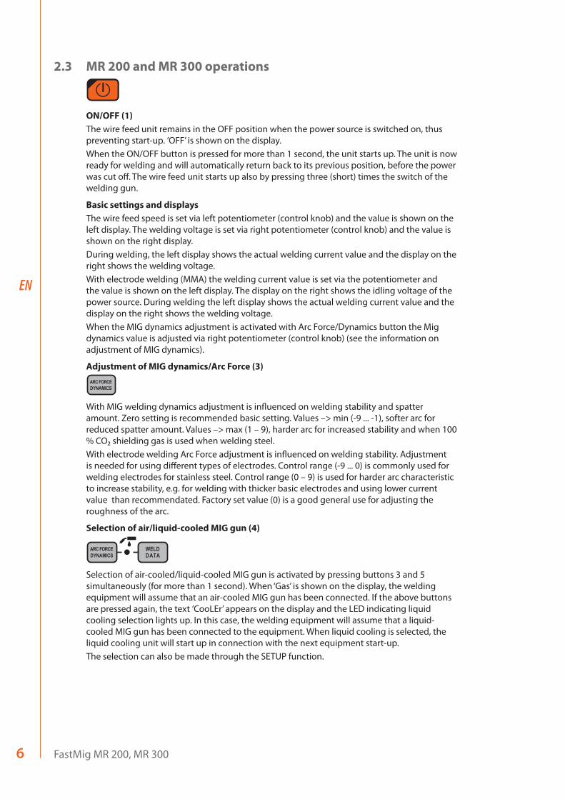
2.3 MR 200 and MR 300 operations
ON/OFF (1)The wire feed unit remains in the OFF position when the power source is switched on, thus preventing start-up. ’OFF’ is shown on the display.When the ON/OFF button is pressed for more than 1 second, the unit starts up. The unit is now ready for welding and will automatically return back to its previous position, before the power was cut off. The wire feed unit starts up also by pressing three (short) times the switch of the welding gun.
Basic settings and displaysThe wire feed speed is set via left potentiometer (control knob) and the value is shown on the left display. The welding voltage is set via right potentiometer (control knob) and the value is shown on the right display.During welding, the left display shows the actual welding current value and the display on the right shows the welding voltage.With electrode welding (MMA) the welding current value is set via the potentiometer and the value is shown on the left display. The display on the right shows the idling voltage of the power source. During welding the left display shows the actual welding current value and the display on the right shows the welding voltage.When the MIG dynamics adjustment is activated with Arc Force/Dynamics button the Mig dynamics value is adjusted via right potentiometer (control knob) (see the information on adjustment of MIG dynamics).
Adjustment of MIG dynamics/Arc Force (3)
With MIG welding dynamics adjustment is influenced on welding stability and spatter amount. Zero setting is recommended basic setting. Values –> min (-9 ... -1), softer arc for reduced spatter amount. Values –> max (1 – 9), harder arc for increased stability and when 100 % CO₂ shielding gas is used when welding steel.With electrode welding Arc Force adjustment is influenced on welding stability. Adjustment is needed for using different types of electrodes. Control range (-9 ... 0) is commonly used for welding electrodes for stainless steel. Control range (0 – 9) is used for harder arc characteristic to increase stability, e.g. for welding with thicker basic electrodes and using lower current value than recommendated. Factory set value (0) is a good general use for adjusting the roughness of the arc.
Selection of air/liquid-cooled MIG gun (4)
Selection of air-cooled/liquid-cooled MIG gun is activated by pressing buttons 3 and 5 simultaneously (for more than 1 second). When ‘Gas’ is shown on the display, the welding equipment will assume that an air-cooled MIG gun has been connected. If the above buttons are pressed again, the text ’CooLEr’ appears on the display and the LED indicating liquid cooling selection lights up. In this case, the welding equipment will assume that a liquid-cooled MIG gun has been connected to the equipment. When liquid cooling is selected, the liquid cooling unit will start up in connection with the next equipment start-up.The selection can also be made through the SETUP function.
FastMig MR 200, MR 3006
EN
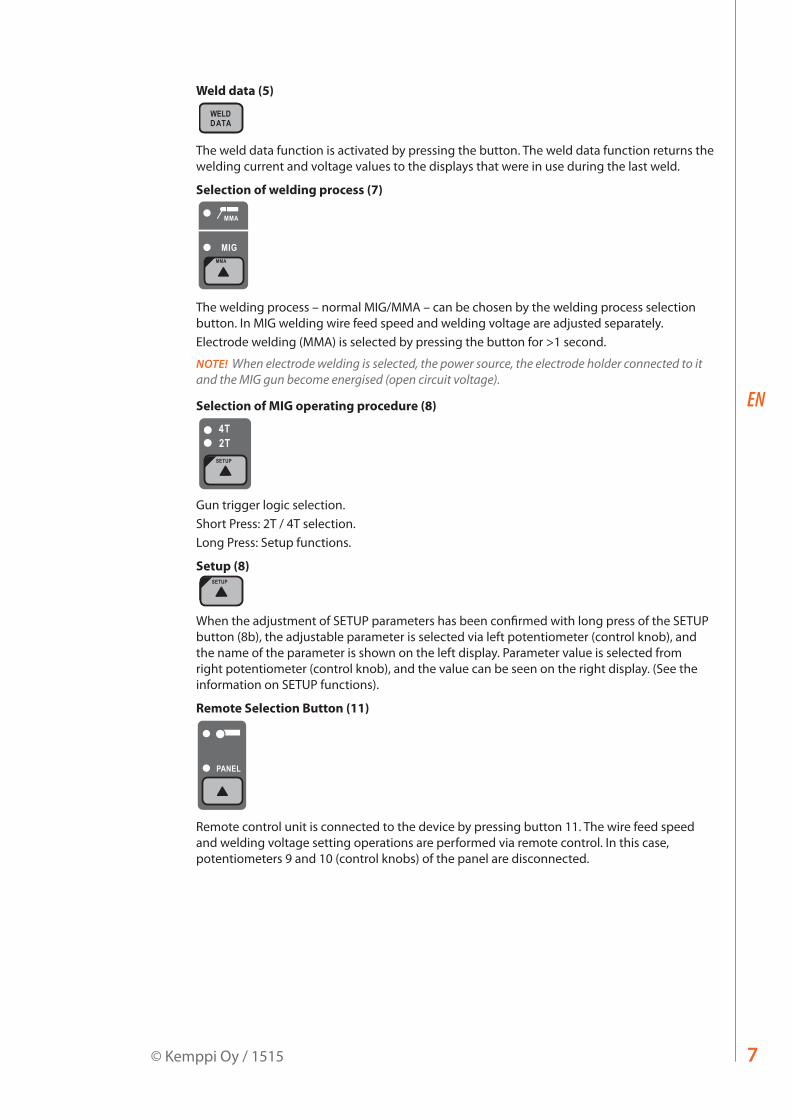
Weld data (5)
The weld data function is activated by pressing the button. The weld data function returns the welding current and voltage values to the displays that were in use during the last weld.
Selection of welding process (7)
The welding process – normal MIG/MMA – can be chosen by the welding process selection button. In MIG welding wire feed speed and welding voltage are adjusted separately. Electrode welding (MMA) is selected by pressing the button for >1 second.
NOTE! When electrode welding is selected, the power source, the electrode holder connected to it and the MIG gun become energised (open circuit voltage).
Selection of MIG operating procedure (8)
Gun trigger logic selection.Short Press: 2T / 4T selection.Long Press: Setup functions.
Setup (8)
When the adjustment of SETUP parameters has been confirmed with long press of the SETUP button (8b), the adjustable parameter is selected via left potentiometer (control knob), and the name of the parameter is shown on the left display. Parameter value is selected from right potentiometer (control knob), and the value can be seen on the right display. (See the information on SETUP functions).
Remote Selection Button (11)
Remote control unit is connected to the device by pressing button 11. The wire feed speed and welding voltage setting operations are performed via remote control. In this case, potentiometers 9 and 10 (control knobs) of the panel are disconnected.
7© Kemppi Oy / 1515

EN
2.4 Panel MR 200 and MR 300 Setup parametersNormal MIG welding Setup -parameters
Name of parameter
Name on display
Parameter values
Factory setting
Description
Pre Gas Time PrG 0.0 – 9.9 s 0,0 s Pre gas time in seconds
Post Gas Time PoG 0.0 – 9.9 s Aut Post gas time in seconds or automatically according to welding current (Aut)
Creep Start Level CrE 10 – 170% 50 % Percentage of wire feed speed: 10 % slowed start 100 % = no creep start function170 % accelerated start
Start Power StA -9 ... +9 0 Strength of start pulse
Post Current Time PoC -9 ... +9 0 Post current
Arc Voltage Ard OFF, on OFF on: Display shows arc voltage OFF: Display shows pole voltage
Cable Length CAb std, 5 – 80m std Cable loss is calculated for optimal arc control and for the Arc Voltage display
Common Setup -parameters for MIG processes
Name of parameter
Name on display
Parameter values
Factory setting
Description
Device Address Add 3 or 6 3 Wire feeder bus address
Using features of PMT Gun
Gun OFF, on on on = PMT gunOFF = other gun
Gas Guard Connected
GG no, YES on Implementation of gas guard
LongSystem Mode LSY OFF, on OFF on: Gives optimum welding characteristics with long welding cables
Code Entry Cod ---, Ent --- Entering license codes manually:1. Adjust right potentiometer to (‘Ent’).2. Press REMOTE.3. Set code with right potentiometer.4. Choose next with left potentiometer.5. Go back to point 3, until all codes have been set.6. Approve by pressing REMOTE. (‘Suc cEs’)
Water Cooler Coo OFF, on on Enables water cooler
Wire Inch Stop Inc OFF, on on OFF = Stops wire inch in case arc does not igniteon = Feeds wire as long as the welding gun start switch is pressed.
Auto Wire Inch AIn OFF, on on SuperSnake Automatic Wire Inch function. Wire Inch button runs the filler wire from the wire feeder up to the SuperSnake.
Demo Licence Time dEt 3-h, 2-h, **’, **’’, OFF
The remaining time for the WiseDemo licence (readable value only).3-h = max. 3 hours left2-h = max. 2 hours left**’ = ** minutes left**’’ = ** seconds leftOFF = Demo period has expired.
FastMig MR 200, MR 3008
EN
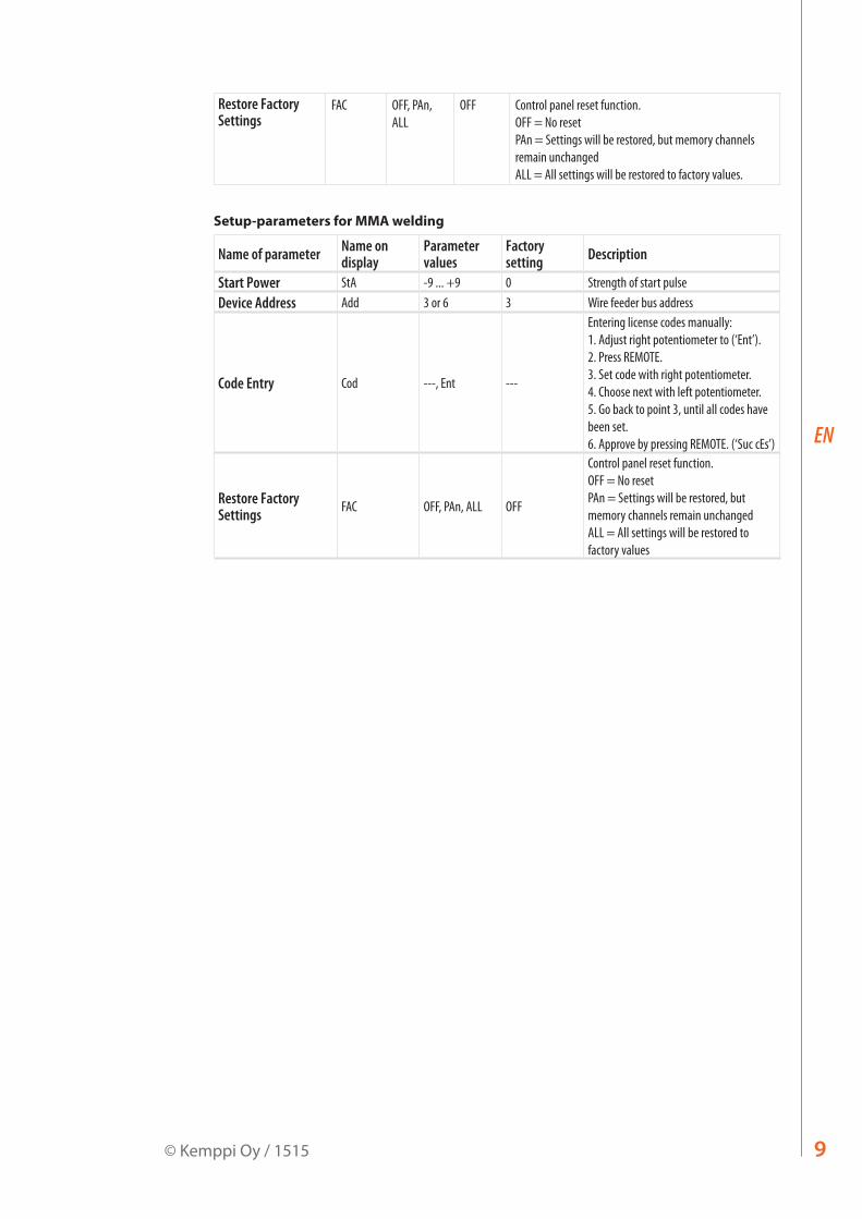
Restore Factory Settings
FAC OFF, PAn, ALL
OFF Control panel reset function.OFF = No resetPAn = Settings will be restored, but memory channels remain unchangedALL = All settings will be restored to factory values.
Setup-parameters for MMA welding
Name of parameter Name on display
Parameter values
Factory setting Description
Start Power StA -9 ... +9 0 Strength of start pulseDevice Address Add 3 or 6 3 Wire feeder bus address
Code Entry Cod ---, Ent ---
Entering license codes manually:1. Adjust right potentiometer to (‘Ent’).2. Press REMOTE.3. Set code with right potentiometer.4. Choose next with left potentiometer.5. Go back to point 3, until all codes have been set.6. Approve by pressing REMOTE. (‘Suc cEs’)
Restore Factory Settings FAC OFF, PAn, ALL OFF
Control panel reset function.OFF = No resetPAn = Settings will be restored, but memory channels remain unchangedALL = All settings will be restored to factory values
9© Kemppi Oy / 1515

EN
3. FASTMIG ERROR CODES
The existence of possible faults in the equipment is investigated in connection with each wire feed unit start-up. If a fault is detected, the fault in question will be indicated as an ’Err’ message on the panel display.
Error code examples:Err 2: Undervoltage
The device has stopped because it has detected a mains undervoltage that disturbs welding. Check the quality of the supply network.Err 3: Overvoltage
The device has stopped because dangerously high temporary voltage surges or a continuous over-voltage has been detected in the electric network. Check the quality of the supply network.Err 4: Power source is overheated
The power source has overheated. The cause may be one of the following:• The power source has been used for a long time at maximum power.• The circulation of cooling air to the power source is blocked.• The cooling system has experienced a failure.
Remove any obstacle to air circulation, and wait until the power source fan has cooled down the machine. Err 5: Water unit alarm
The water circulation is blocked. The cause may be one of the following:• Congestion or disconnection in the cooling pipeline• Insufficient cooling liquid• Excessive cooling liquid temperature
Check the circulation of the cooling liquid and the air circulation of the water unit. Err 54: No data communication from power source
The data transmission between the power source and the wire feed unit has been cut off or is defective. Check the extension lead and connections.Err 55: Power source is busy
The communication channel is busy. The power source is being used by another wire feed unit or the programming for some other device in the channel (e.g. control panel) is in progress.Err 61: The water unit is not found
Water unit is not connected to the equipment or there is a connection fault.Connect up the water unit or change the setting of the unit to air-cooled, if you are using a air-cooled welding gunErr 153: Overheating of liquid-cooled PMT gun
When starting to weld or during welding, the overheat protection on the liquid-cooled MIG welding gun has activated. Check that there is sufficient liquid in the cooling unit and that air is circulating freely through it. Ensure that liquid is circulating freely through the cooling hoses.Err 154: Overloading of the wire feed motor
The welding has been interrupted because the loading of the wire feed motor has risen to a high level. The cause of this could be a blockage of the wire line. Check the wire conduit, contact tip and feed rolls.Err 155: Warning of the wire feed unit overloading
The wire feed motor load level has risen. The cause could be dirty wire conduits or a gun cable twisted into sharp curves. Check the state of the gun and clean the wire line if necessaryErr 165: Gas guard alarm
Gas guard function has worked, because the pressure of gas has decreased. Possibly reasons: Gas is unconnected to the wire feeder. Gas has been ran out, gas hose is leaking or there is no pressure enough in the gas web. Connect the gas to the wire feeder, check gas hose and the pressure of the gas web.
FastMig MR 200, MR 30010
EN
Err 171: Configuration not found for the device
The equipment’s internal data transmission has been cut off. The optional features cannot be used. Turn off the machine, detach the welding gun and re-start the machine. If an error code does not appear in the display, the fault lies in the welding gun. If this error code pertains, contact maintenance.Err 172: A wrong configuration code has been supplied
License activation with DataGun has failed. Turn off the machine, detach DataGun and restart the machine. Reconnect DataGun. If this error code recurs, contact maintenance.Err 201: Use of PMT gun is prevented
You try to use the PMT welding gun, but the necessary settings have not been entered into the machine’s control panel. Select ‘PMT gun’ from the control panel SETUP menu, if you wish to use it. This fault can also occur with other guns, if the trigger contacts are bad or dirty.Err 221: Two wire feeders connected with the same device address.
Two wire feed units have the same device address. Define different addresses for the devices as follows:1. Press any button on either control panel (except the ESC button). “Add” (Device Address)
is displayed. 2. Change the device address using the right-hand control knob. 3. Return to normal status by pressing again any button on the control panel. The machines will return to normal status within 15 seconds.
Other error codes:The machine can show codes not listed here. In the event of an unlisted code appearing, contact an authorised Kemppi service agent and report the error code shown.
4. DISPOSAL
Do not dispose of electrical equipment with normal waste!In observance of European Directive 2002/96/EC on waste electrical and electronic equipment, and its implementation in accordance with national law, electrical equipment that has reached the end of its life must be collected separately and taken to an appropriate environmentally responsible recycling facility. The owner of the equipment is obliged to deliver a decommissioned unit to a regional collection centre, per the instructions of local authorities or a Kemppi representative. By applying this European Directive you will improve the environment and human health.
5. ORDERING NUMBERS
FastMig MR 200 MXF 63 6136100
FastMig MR 300 MXF 65, MXF 67 6136200
11© Kemppi Oy / 1515

www.kemppi.com
19034901515
KEMPPI OYKempinkatu 1PL 13FIN-15801 LAHTIFINLANDTel +358 3 899 11Telefax +358 3 899 [email protected]
Kotimaan myynti:Tel +358 3 899 11Telefax +358 3 734 [email protected]
KEMPPI SVERIGE ABBox 717S-194 27 UPPLANDS VÄSBYSVERIGETel +46 8 590 783 00Telefax +46 8 590 823 [email protected]
KEMPPI NORGE A/SPostboks 2151, PostterminalenN-3103 TØNSBERGNORGETel +47 33 346000Telefax +47 33 [email protected]
KEMPPI DANMARK A/SLiterbuen 11DK-2740 SKOVLUNDEDANMARKTel +45 4494 1677Telefax +45 4494 [email protected]
KEMPPI BENELUX B.V.NL-4801 EA BREDANEDERLANDTel +31 765717750Telefax +31 [email protected]
KEMPPI (UK) LTD Martti Kemppi BuildingFraser RoadPriory Business ParkBEDFORD, MK44 3WHUNITED KINGDOMTel +44 (0)845 6444201
Telefax +44 (0)845 [email protected]
KEMPPI FRANCE S.A.S.65 Avenue de la Couronne des Prés78681 EPONE CEDEXFRANCETel +33 1 30 90 04 40Telefax +33 1 30 90 04 [email protected]
KEMPPI GMBHPerchstetten 10D-35428 LANGGÖNSDEUTSCHLANDTel +49 6 403 7792 0Telefax +49 6 403 779 79 [email protected]
KEMPPI SPÓŁKA Z O.O.Ul. Borzymowska 3203-565 WARSZAWAPOLANDTel +48 22 7816162Telefax +48 22 [email protected]
KEMPPI AUSTRALIA PTY LTD13 Cullen PlaceP.O. Box 5256, Greystanes NSW 2145SMITHFIELD NSW 2164 AUSTRALIATel. +61 2 9605 9500Telefax +61 2 9605 [email protected]
OOO KEMPPIPolkovaya str. 1, Building 6127018 MOSCOWRUSSIATel +7 495 240 84 03Telefax +7 495 240 84 [email protected]
ООО КЕМППИул. Полковая 1, строение 6127018 МоскваTel +7 495 240 84 03Telefax +7 495 240 84 [email protected]
KEMPPI, TRADING (BEIJING) COMPANY LTDUnit 105, 1/F, Building #1, No. 26 Xihuan South Rd.,Beijing Economic-Technological Development Area (BDA),100176 BEIJINGCHINATel +86-10-6787 6064+86-10-6787 1282Telefax +86-10-6787 [email protected]
肯倍贸易(北京)有限公司中国北京经济技术开发区 西环南路26号1号楼1层105室(100176)电话:+86-10-6787 6064/1282传真:+86-10-6787 [email protected]
KEMPPI INDIA PVT LTDLAKSHMI TOWERSNew No. 2/770, First Main Road, Kazura Garden, Neelankarai, CHENNAI - 600 041 TAMIL NADUTel +91-44-4567 1200Telefax +91-44-4567 [email protected]
KEMPPI WELDING SOLUTIONS SDN BHDNo 12A, Jalan TP5A,Taman Perindustrian UEP,47600 Subang Jaya, SELANGOR, MALAYSIATel +60 3 80207035Telefax +60 3 [email protected]