Embed Size (px)
Citation preview

Part No. HF11099.Rev.8.00 Issued April 2017 Printed in Canada
HAC/QHAC SeriesHorizontal Air Curtain and Quiet Horizontal Air Curtain
Installation, Operation, & Maintenance Instructions
IMPORTANT INSTRUCTIONS - SAVE THESE INSTRUCTIONS Read all instructions before installing or using the horizontal air curtain. Please adhere to instructions published in this manual. Failure to do so may be dangerous and may void certain provisions of your warranty.
Fastrax® is a registered trademark of CCI Thermal Technologies Inc. Copyright© 2017. All rights reserved.
QHAC Series
HAC Series

22Part No. HF11099
Impo
rtan
t Not
ices
& W
arni
ng S
ymbo
ls
TABLE OF CONTENTS
A. Important Notices And Warning Symbols 2
B. Overview 2B.1 Introduction ...........................................................2
B.2 Specifications ........................................................3
C. Installation Overview 4C.1 General ..................................................................4
C.2 Recommended Tools ............................................4
C.3 Site Preparation ....................................................4
D. Crib Duct System Installation 5D.1 General ..................................................................5
D.2 Fastrax® Horizontal Air Curtains Site Layout & Clearances ............................................................6
D.3 Site Preparation .....................................................7
E. Tie Duct System Installation 11E.1 General ................................................................ 11
E.2 HAC Series Layout .............................................. 11
E.3 QHAC Series Layout ...........................................12
E.4 Installing Tie Duct ................................................13
F. Electrical Connections 14F.1 General ................................................................14
G. Operation 19G.1 General ...............................................................19
G.2 Thermostat .........................................................19
G.3 Motor Overload Protection ..................................19
G.4 Delay Start Timer ................................................19
H. Inspection 20H.1 General................................................................20
H.2 Prior to Annual Start Up ......................................20
I. Maintenance 21I.1 General .................................................................21
I.2 Lubrication ............................................................21
I.3 Motor/Impeller/Base Assembly Removal ...............21
I.4 Impeller Removal ..................................................21
J. Troubleshooting 22
K. Parts 23K.1 Nozzles and Ductwork ........................................23
K.2 Blower Systems - Fastrax® HAC Series .............25
K.3 Blower Systems - Fastrax® QHAC Series ...........25
K.4 Electrical Components ........................................26
A. IMPORTANT NOTICES AND WARNING SYMBOLS
Keep this manual with the machine at all times. The purpose of this manual is to provide owners, operators, and installers with the precautions and procedures essential for the safe and proper operation for its intended purpose.
CAUTION
CAUTION. This symbol indicates a potentially hazardous situation, which, if not avoided, may result in personal injury or damage to the equipment.
WARNING. This symbol indicates an imminently hazardous situation, which, if not avoided, can result in serious injury or damage to the equipment.
WARNING
WARNING. Read and adhere to the following. Failure to do so may result in severe or fatal injury. Warranty will be void.
WARNING
NOTE: “NOTE:” indicates information or a company policy that relates directly or indirectly to the safety of personnel or protection of property.
B. OVERVIEW
B.1 Introduction
Fastrax® HAC Series (Standard Horizontal Air Curtains) & QHAC Series (Quiet Horizontal Air Curtains) produce a high velocity curtain of ambient air to prevent the accumulation of ice and snow from entering switches. These horizontal air curtains consist of a compact blower unit and ducting system that delivers airflow to the switch
mechanism. The blower unit is an electrically powered centrifugal fan equipped with a low velocity air intake. The blower output is ducted below the rails to nozzles mounted within the railway switch. From the two nozzles, 120 - 140 mph high velocity air streams are directed towards the point of the switch.

33Part No. HF11099
QHAC Series - Crib Duct Assembly
HAC/QHAC Series - Tie Duct Assembly
HAC Series - Crib Duct Assembly
Air IntakeIntegrated Acoustic Enclosure,Intake, and Motor Rain Cover
Blower
Transition Duct
Cross Duct
End Duct
Electrical Box
Motor Rain Cover
Motor
Nozzles
Blower
Transition Duct
Cross Duct
End Duct
Motor
Nozzles
Transition Duct
Tie Duct
Flexible Hose
Deflectors
Ballast Retainer
End Duct
Nozzles
Overview
B.2 Specifications
1. Performance:
1.1 5 HP HAC delivers airflow of 2500 cfm at a peak nozzle velocity of 120 mph, and is typically recommended for yard switches no longer than #14 and clears 15 to 18 ft of switch.
1.2 7.5 HP HAC delivers airflow of 3000 cfm at a peak nozzle velocity of 140 mph, and is recommended for mainline switches no longer than #20 and clears 18 to 20 ft of switch.
2. Track: 56.5” gauge, and 100 lb rail or heavier.
3. Noise Pressure Levels:
3.1 HAC Series - 65 dbA at 50 ft
3.2 QHAC Series - 60 dbA at 50 ft
4. Construction:
– 11 gauge cold rolled steel, including nozzles
– Hot dipped galvanized blower, intake and duct work
– Direct drive centrifugal blower
– Stainless steel electrical box
– Match balanced motor and impeller sets, to less than 0.2 ips pk-pk
5. Size & Operating Voltage: 5 or 7.5 HP, 208/240/460/575VAC, 3 phase or single 240VAC single phase.
6. Controls:
– Weather-tight NEMA 3R electrical enclosure
– REMOTE/AUTO/MANUAL modes
– Magnetic motor starter complete with thermal overload protection
7. Terminal Block Wire Size: #14 to #2 AWG copper
8. Electrical Isolation: Ducting, nozzle connections and unistruts are electrically isolated to eliminate the possibility of short circuiting rails. Connections are designed and tested to withstand a maximum of 1500VAC for 3 seconds.

44Part No. HF11099
Inst
alla
tion
Ove
rvie
w
C. INSTALLATION OVERVIEW
C.1 General
This manual provides general guidelines for the installation of typical Fastrax® HAC & QHAC Series Horizontal Air Curtain and duct work. For customized systems, they should be followed in conjunction with specific site layout drawings provided.
It is recommended that the Fastrax® HAC & QHAC Series Horizontal Air Curtain be located on the opposite side of the track from the switch motor to avoid potential interference with either the motor, junction boxes or electrical lines, although it can be located on either side.
If the blower location is obstructed, optional ducting elbows and extensions are available as separate items.
The Fastrax® HAC & QHAC Series Horizontal Air Curtain and duct work are shipped in two packages. The ducting is wrapped together on a skid and the Fastrax® HAC & QHAC Series Horizontal Air Curtain on another, as shown.
C.2 Recommended Tools
• A source of power to operate power tools (portable generator)
• Back hoe
• Impact wrench, 1/2” drive with 1/2”, 9/16” and 3/4” sockets
• Drill, 3/8” drive and drill bits
• Two 9/16” wrenches and/or socket wrench
• Lining and tamping bars
• Sledge hammer
• Shovels
• Reciprocating Saw
• Cold Chisel and hammer
• Measuring tape
• Multimeter
• Clip on ammeter
• 4 foot Level
C.3 Site Preparation
There are two duct systems, crib duct and tie duct. Crib duct system is installed between the ties, while tie duct systems replace a tie. Follow the appropriate instructions for your system.
HAC Series
Ductwork
QHAC Series

5Part No. HF11099
Crib D
uct System
Installation
DIFFUSER GASKET ORCROSS DUCT GASKET
HEX NUT, 3/8 - 16 UNC. (Qty 8)
3/8 NOM., F/WHR. (Qty 8)
CAP SCREW, 3/8 - 16 UNC. X 1-50” LG., GR.5, STEEL (Qty 8)
3/8 NOM., F/WHR. (Qty 8)
NYLON SHLDR. WHR.(Qty 16)
Detail ‘A’ - Diffuser and Cross Duct Gasket Kit Hardware
D. CRIB DUCT SYSTEM INSTALLATION
D.1 General
1. Specifics of the site preparation vary depending on the clearance layout and the type of system ordered. See Section D.2 - Fastrax® HAC Series Horizontal Air Curtains Site Layout or Section D.3 - Fastrax® QHAC Series Quiet Horizontal Air Curtains Site Layout. For customized installations, refer to the supplied site layout drawing.
QHAC Series - Crib Duct Assembly
HAC/QHAC Series - Tie Duct Assembly
HAC Series - Crib Duct Assembly
Air IntakeIntegrated Acoustic Enclosure,Intake, and Motor Rain Cover
Blower
Transition Duct
Cross Duct
End Duct
Electrical Box
Motor Rain Cover
Motor
Nozzles
Blower
Transition Duct
Cross Duct
End Duct
Motor
Nozzles
Transition Duct
Tie Duct
Flexible Hose
Deflectors
Ballast Retainer
End Duct
Nozzles
66Part No. HF11099
Crib
Duc
t Sys
tem
Inst
alla
tion
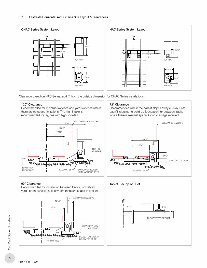
D.2 Fastrax® Horizontal Air Curtains Site Layout & Clearances
Top of Tie/Top of Duct
120” ClearanceRecommended for mainline switches and yard switches where there are no space limitations. The high intake is recommended for regions with high snowfall.
90” ClearanceRecommended for installation between tracks, typically in yards or on curve locations where there are space limitations.
72” ClearanceRecommended where the ballast slopes away quickly. Less backfill required to build-up foundation, or between tracks where there is minimal space. Good drainage required.
CLEARANCE ENVELOPE
BOTTOM OF BLOWERLEVEL WITH TOP OF TIE
RAILWAY TIESTOP OF TIE/TOP OF DUCT
155.0”
120.5”
100.3”
72.0”
64.0” HIGHAIR INTAKE
BLOWER BASE IS 5.7”BELOW TOP OF TIE
26.1” EXTRA LOWAIR INTAKE
CLEARANCE ENVELOPE
RAILWAY TIES
124.5”
90.0”
CLEARANCE ENVELOPE
RAILWAY TIES
106.8”
72.3”
20.2”
11.6” BELOW TOP OF TIE
Clearance based on HAC Series, add 4” from the outside dimension for QHAC Series installations.
TOP OF TIE/TOP OF DUCT
0.75”1.25”
HAC Series System Layout
SIDE VIEW
TOP VIEW
SIDE VIEW
TOP VIEW
40.0”
54.4”
30.5”
32.0”
25.5”
52.7”
34.5”
31.8”
QHAC Series System Layout
77Part No. HF11099
Crib D
uct System
Installation
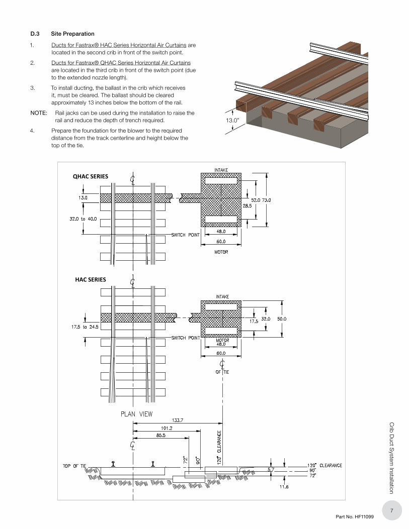
D.3 Site Preparation
1. Ducts for Fastrax® HAC Series Horizontal Air Curtains are located in the second crib in front of the switch point.
2. Ducts for Fastrax® QHAC Series Horizontal Air Curtains are located in the third crib in front of the switch point (due to the extended nozzle length).
3. To install ducting, the ballast in the crib which receives it, must be cleared. The ballast should be cleared approximately 13 inches below the bottom of the rail.
NOTE: Rail jacks can be used during the installation to raise the rail and reduce the depth of trench required.
4. Prepare the foundation for the blower to the required distance from the track centerline and height below the top of the tie.
13.0”
HAC SERIES
QHAC SERIES
88Part No. HF11099
Crib
Duc
t Sys
tem
Inst
alla
tion
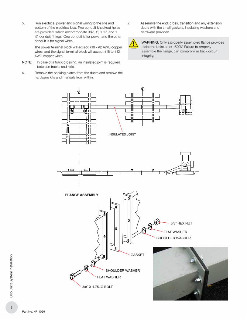
5. Run electrical power and signal wiring to the site and bottom of the electrical box. Two conduit knockout holes are provided, which accommodate 3/4”, 1”, 1 ¼”, and 1 ½” conduit fittings. One conduit is for power and the other conduit is for signal wires.
The power terminal block will accept #10 - #2 AWG copper wires, and the signal terminal block will accept #18 to #12 AWG copper wires.
NOTE: In case of a track crossing, an insulated joint is required between tracks and rails.
6. Remove the packing plates from the ducts and remove the hardware kits and manuals from within.
7. Assemble the end, cross, transition and any extension ducts with the small gaskets, insulating washers and hardware provided.
WARNING. Only a properly assembled flange provides dielectric isolation of 1500V. Failure to properly assemble the flange, can compromise track circuit integrity.
WARNING
INSULATED JOINT
3/8” HEX NUT
FLAT WASHER
FLAT WASHER
SHOULDER WASHER
SHOULDER WASHER
GASKET
3/8” X 1.75LG BOLT
FLANGE ASSEMBLY

99Part No. HF11099
Crib D
uct System
Installation
8. Slide the assembled ducts into position.
9. Using pry and tamping bars, move, level and stabilize the ducting, so the nozzle openings are centered with the middle (center line) of the track, and the top of the duct (excluding flanges) is level with the top of the tie.
10. Install the swivel nozzles onto the duct with the gasket, insulating washers and hardware. Adjust the nozzle vanes to their optimum setting. To properly direct the airflow to the point of the switch, swivel each nozzle until it is approximately 1-1/2 to 2 inches from the inside edge of the track, or as close as regulations permit, and tighten the nozzle hardware.
FIGURE 15 - INSTALL AND ADJUST NOZZLES
FIGURE 15 - INSTALL AND ADJUST NOZZLES
DIRECTION OF AIR FLOW
56.50”TRACK GAUGE
DIRECTION OF AIR FLOW
OPTIMUMVANE SETTING
FACTORYVANE SETTING
DETAIL ‘A’FOR OPTIMUM AIR FLOW DISTRIBUTION BOTHNEAR AND FAR ADJUSTABLE NOZZLE VANESSHOULD BE SET AS DEPICTED ABOVE
50.33”NORMAL
0/5 OF NOZZLE
45.50”MIN
0/5 OF NOZZLE
53.88”MAX
0/5 OF NOZZLE

1010Part No. HF11099
Crib
Duc
t Sys
tem
Inst
alla
tion
11. Using supplied lag bolts and washers, fasten the two 48” length ties to the base of the blower through the holes provided.
12. The blower assembly weighs approximately 650 pounds. If a crane is available, sling the blower and swing it into position. Align the blower flange with the transition flange and assemble with the large gaskets, insulating washers and hardware.
13. Shim beneath the blower as required to make the top of the blower level. Backfill underneath the blower then remove slings. Ensure that the blower is not twisted or distorted. Backfill level with the top of the wood tie foundation.
14. Using pry and tamping bars, move, level and stabilize the ducting so that the nozzle openings are centered about the center line of the track, and the top of duct (excluding the flanges) is level with the top of the tie.

1111Part No. HF11099
Tie Duct S
ystem Installation
E. TIE DUCT SYSTEM INSTALLATION
E.1 General
1. Specifics of the site preparation vary depending on the clearance layout and the type of system ordered, either standard or quiet. For customized installations, refer to the supplied site layout drawing.
E.2 HAC Series Layout
116” / 0” RISE - CLEARANCE
116” / 5” RISE - CLEARANCE
126” / 11.75” RISE - CLEARANCE
LAYOUT - TOP VIEW

1212Part No. HF11099
Tie
Duc
t Sys
tem
Inst
alla
tion
E.3 QHAC Series Layout
116” / 0” RISE - CLEARANCE
116” / 5” RISE - CLEARANCE
126” / 11.75” RISE - CLEARANCE
LAYOUT - TOP VIEW

1313Part No. HF11099
Tie Duct S
ystem Installation
E.4 Installing Tie Duct
1. Select and remove the tie (typically the second or third tie in front of the switch points) to be replaced by the tie duct at the switch point. Install a minimum 20” in front of the switch points.
2. Dig a 16” deep trench to allow the tie duct to slide in underneath the rail. Orientate the tie duct with the open flange facing the blower location. The ends are removable to allow installation prior to determining the blower position. Centre the tie duct between the two adjacent ties, raise the tie duct and secure it to the rail with the rail fasteners and insulators supplied.
WARNING. Do not install tie duct in place of a gage plate. Do not install between the switch points and the stock rail bend.
WARNING
WARNING. Tie duct MUST BE attached with supplied rail pads and clip insulators to provide electrical insulation from track to AAR standards, maintain track circuit integrity, and to provide full structural strength.
WARNING
3. Attach the square to round adapter to the transition using the hardware provided, and the transition to the blower.
4. Position the ballast retainer between the square to round adapter and the tie duct. Allow the retainer to overlap the square to round adapter and the tie duct by several inches.
5. Remove the tie wraps that secure the compressed flex hose. Slide the black protective sleeve over the flex hose until it is centered.
6. Roll the ends of the protective sleeve back, compress the hose and install. Leave as much slack as possible and avoid stretching the flex duct.
7. Once installed, unroll the ends of the protective sleeve. Install the 2 gear clamps (Part No HF9022-3008) over the protective sleeve to seal the ends.
8. Bolt the cover to retainer. Stabilize and tamp the duct and ties.
NOTE: Backfill with clean ballast only.
Remove seal from tie duct
Cover
Flexible Hose
Gear Clamps
Ballast Retainer

1414Part No. HF11099
Ele
ctric
al C
onne
ctio
ns
F. ELECTRICAL CONNECTIONS
F.1 General
WARNING. Electrical connections are to be performed by personnel approved by the local electrical authority.
Units must be wired in accordance with electrical code.
WARNING
1. Power must be brought to the HAC/QHAC through a customer supplied service line. The fuse ratings are dependent on the motor full load amps and should be the ‘motor start, time delay’ type.
2. The following three tables can be used as an aid to select the appropriate size wire based on the running amps of the HAC/QHAC, the distance to the power supply, and the maximum allowable voltage drop. The recommended maximum voltage drop is 3% to 5%.
NOTE: Actual running amperage varies significantly with temperature and running voltage.
Amperage Calculation Example:
What will be the actual amperage draw of a 7.5 Hp VAC HAC, when the temperature is -30°C and the running voltage is 220V?
= Nameplate FLA x (Nameplate Voltage/Actual Voltage) x (Temperature Factor/100)= 33.0 x (230/220) x (110/100)= 38.0 Amps
Table 1 – HAC/QHAC Full Load Running Amps @ -10°C
HP Motor Volts Ph FL Amps
5
208 3 13.2
230 1 21.0
460 3 6.0
575 3 5.1
7.5
208 3 21.0
230 1 33.0
460 3 9.5
575 3 7.9
Table 2 – Running Amperage vs. Temperature
Ambient Temperature Running Amps% of FLA°C °F
20 68 85
10 50 90
5 41 93
0 32 95
-5 27 98
-10 14 100
-15 5 103
-20 -4 105
-25 -13 108
-30 -22 110
-35 -31 113
-40 -40 115
Table 3 – Recommended Circuit Breaker Sizes (Voltage Drop vs. Current Draw for Copper Wire)
Voltage Drop/1000 ft
Wire Size (AWG)
10 8 6 4 2 Recommended Circuit Breaker
Size*Ohms/ 1000 ft
1.00 0.65 0.41 0.026 0.016
5 5.0 3.3 2.0 1.3 0.8 15
10 10.0 6.5 4.1 2.6 1.6 20
15 15.0 9.8 6.1 3.9 2.4 30
20 20.1 13.0 8.2 5.1 3.2 50
25 25.1 16.3 10.2 6.4 4.1 60
30 30.1 19.5 12.3 7.7 4.9 70
35 35.1 22.8 14.3 9.0 5.7 100
40 40.1 26.0 16.4 10.3 6.5 100
*Standard HAC power terminal block will accept #14 to #2 AWG copper wire *Allowable voltage drop to be determined by local authority *Recommended voltage drop of not more than 5% *As per Canadian Electrical Code, Part 1
3. Terminals are provided for all power, control, indication and ground wires.
4. For remote control applications, the customer must supply a set of contacts with a minimum rating of 240Vac, 1 amp. If indication is required, the customer can use the indication contacts that are rated at 240Vac, 10 amps.
5. Connect the HAC according to the applicable schematic. Two conduit holes are provided, which accommodate 3/4” conduit fittings, one for the power and one for the signal wires. These are located in the bottom of the electrical box. The power terminal block will accept #10 - #2 AWG copper wires, and the signal terminal block will accept # 18 - #12 AWG copper wires.
6. Energize the circuit. Switch the HAC/QHAC on by turning the selector switch to manual in the electrical box. Ensure that the blower wheel is turning freely.
7. For three phase motors, CONFIRM CORRECT FAN ROTATION.
7.1 Check that the motor/fan is rotating in the same direction as the arrow mounted on the fan housing above the motor. Or, if the motor is not visible, as for a QHAC, or an HAC with a rain cover,
7.2 Check that the motor run amps do not exceed the motors Full Load Amps (FLA) by more than 15%.
7.3 Check the HAC/QHAC performance, if significantly reduced, the fan is rotating the wrong way.
8. If the rotation is incorrect, turn off the power to the HAC/QHAC at the local disconnect and interchange any two of the power lines, ie. L1 with L2, L2 with L3, or L1 with L3 at the terminal block.

1515Part No. HF11099
CC
I TH
ERM
AL T
ECH
NO
LOG
IES
INC
.
1616Part No. HF11099
CC
I TH
ERM
AL T
ECH
NO
LOG
IES
INC
.
1717Part No. HF11099
CC
I TH
ERM
AL T
ECH
NO
LOG
IES
INC
.

1818Part No. HF11099
CC
I TH
ERM
AL T
ECH
NO
LOG
IES
INC
.

1919Part No. HF11099
Operation
G. OPERATION
G.1 General
WARNING. In order for the HAC/QHAC to perform satisfactorily, the unit must be turned ‘ON’ prior to snow fall or freezing rain.
WARNING
1. The HAC/QHAC keeps snow and freezing rain from fouling the switch, but cannot recover a switch full of snow and ice.
2. There are three methods of starting:
– MANUALLY, by turning the selector switch to ‘ON’,
– REMOTELY, when the selector switch is set on ‘AUTO’ and the customer supplied contacts are closed,
– AUTOMATICALLY, on units supplied with a temperature switch, when the selector switch is set to ‘AUTO’ and the ambient temperature drops below the temperature switch set point.
NOTE: The “AUTO” and “REMOTE” controls work in parallel. With the selector switch in “AUTO”, either the thermostat or the dispatch control can start the HAC/QHAC. Both must be open, in order for the HAC/QHAC to turn off.
3. The HAC/QHAC must be turned on before it starts to snow or rain since its function is to prevent the build up of snow and ice rather than to remove it. Let the HAC/QHAC run for sufficient time after a snowfall to prevent the accumulation of drifting snow or snow dragged in by passing trains.
4. For maximum switch clearing performance, leave the HAC/QHAC running for the entire winter. This ensures the HAC/QHAC will be on before any snow can fall into the switch, and the continuous operation will sublimate any frost build-up.
or
5. To conserve energy the HAC/QHAC can be turned off whenever weather conditions permit.
G.2 Thermostat
1. The thermostat is located inside the electrical box.
2. To activate the temperature switch, turn the control panel selector switch to ‘AUTO’.
3. For most effective operation, it is recommended that the front dial of the temperature switch be set to 3°C (37°F).
The differential setting on the unit has been factory set at 2°C (36°F). With these settings the unit will turn on when the temperature drops to 3°C (37°F) and continue running until the ambient temperature rises above 5°C (41°F).
4. Operation in ‘AUTO’ mode with the temperature switch will limit the Fastrax® HAC/QHAC running time saving electrical energy and increasing unit life expectancy.
G.3 Motor Overload Protection
1. Inside the electrical cabinet is an “over current” protection device. The purpose of this device is to protect the motor from continuous overload current.
1.1 Overload current can occur as a result of repeated starts and stops within a short period of time, low supply voltage, incorrectly installed fan, or bearing failure.
2. The thermal overload dial is set to the motors nameplate full load amperage X 1.0.
3. DO NOT increase dial setting.
4. The ‘RESET’ selector switch is set to ‘MANUAL’.
5. DO NOT set to ‘AUTOMATIC’.
6. Once tripped the overload requires 5 to 10 minutes before it can be reset.
7. To reset, push the blue ‘RESET’ button.
G.4 Delay Start Timer
1. For multiple blower installations controlled by one start relay, a delay start timer can be added to each individual blower. This allows staggered start up, reduces the maximum inrush current and reduces power cable size.
2. Set the delay by toggling the dip switches to ‘ON’. The combined total is the delay time.

2020Part No. HF11099
Insp
ectio
n
H. INSPECTION
H.1 General
1. The frequency of inspection is dependent on local conditions, but should not be less than once annually.
H.2 Prior to Annual Start Up
1. Visually inspect the installation to check that all parts are secure, free from damage, and firmly fastened together.
2. Inspect the lag bolts, which fasten the Fastrax® HAC/QHAC to its wood tie foundation, and ensure they are firmly fastened.
3. Start the Fastrax® HAC/QHAC.
4. Check for any undue vibration or noise at the blower and ensure that air is blowing freely from both nozzles.
Location Mounting Channel Motor Bearing
Vibration Level in/sec (rms)
Less than 0.1
0.04 to 0.12 Acceptable
0.13 to 0.29 Tolerable
0.30 to 0.71 Excessive
0.72 or more Extreme
Units leave the plant with no more than 0.20 in/sec (rms), this is the
maximum acceptable vibration level.
4.1 A vibration PEN may be purchased from CCI Thermal to check the vibration level of the equipment, Part No HF9074-0013.
4.2 Motor bearing vibration levels (refer to diagram numbered 1 to 4) can be charted on a graph ‘motor bearing vibration levels vs time’ to predict when the motor requires replacement or maintenance.
4.3 Mark locations (1 to 4) on motor to ensure repeatable measurements for trend analysis.
4.4 Do not measure on covers or guards.
4.5 If vibration levels on the mounting channels exceed 0.1, ensure that mounting ties are fully supported and lag bolts fully tightened.
5. Examine all joints for leaks.
6. Examine exposed duct surfaces for leaks from puncture and/or corrosion.
7. Measure the supply voltage at the power terminal block. It is to be within 5% of the motor nameplate voltage.
8. Using a clip on ammeter, measure the running amps. It is to be within 85% to 115% of the motor nameplate running amps. Running amps greater than 115%, the motor rated full load amps, can indicate failed bearings, incorrect fan/intake clearance from an improperly installed fan, excessive air leaks in the duct work, inadequately sized power supply wires, or poor electrical connections.
2121Part No. HF11099
Maintenance
I. MAINTENANCE
I.1 General
1. Replace all damaged intake ducts, cross ducts, and nozzles since damaged ducts will degrade snow clearing ability.
2. With the supply power turned off, tighten all mounting and electrical connections to the recommended tightening torques.
Thread Size Tightening Torque (in. lbs)
8 - 32 19
10 - 32 31
7/16-20, Power Terminal Lugs 120
I.2 Lubrication
WARNING. Over greasing can cause premature bearing failure.WARNING
1. Motor manufacturers recommend that each unit be started and operated for approximately 1/2 hour per month during the off season.
2. Motors that are provided with grease nipples must be greased at the recommended intervals, before each winter season.
3. GE Motors: Once every year based on seasonal operation, with General Electric D6-A2C5 grease, or equivalent. Remove plug for grease relief. Clean grease relief of any hardened grease. Clean grease nipple fitting of any dirt. Using a low-pressure hand operated grease gun, pump in clean recommended grease until new grease appears at the relief hole. After lubricating, allow the motor to run for ten minutes before replacing relief plug.
4. Baldor Motors: Once every year based on seasonal operation, with Shell, “Dolium R”, Chevron SRI #2”, or Texaco “Premium RB”.
4.1 Clean tip of grease fitting and apply hand-operated grease gun. Use 1-2 full strokes only.
I.3 Motor/Impeller/Base Assembly Removal
1. To gain access to the motor:
1.1 Remove the motor cover from the Fastrax® HAC, or the end panel from a QHAC.
1.2 Disconnect power wires from the motor junction box.
1.3 Remove the bolts that fasten the motor mount and access panel to the blower housing.
1.4 Remove motor/impeller/base assembly.
NOTE: CCI Thermal strongly recommends either the complete motor/impeller/base assembly be replaced as a set or the old assembly be returned for repair and balancing.
WARNING. Replacing the motor or the impeller only, without dynamic balancing, voids warranty, causes rough operation, unacceptable vibration levels, leading to premature bearing failure.
WARNING
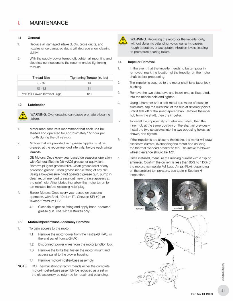
I.4 Impeller Removal
1. In the event that the impeller needs to be temporarily removed, mark the location of the impeller on the motor shaft before proceeding.
2. The impeller is secured to the motor shaft by a taper lock bushing.
3. Remove the two setscrews and insert one, as illustrated, into the middle hole and tighten.
4. Using a hammer and a soft metal bar, made of brass or aluminum, tap the outer half of the hub at different points until it falls off of the inner tapered hub. Remove the inner hub from the shaft, then the impeller.
5. To install the impeller, slip impeller onto shaft, then the inner hub at the same position on the shaft as previously. Install the two setscrews into the two opposing holes, as shown, and tighten.
6. If the impeller is too close to the intake, the motor will draw excessive current, overloading the motor and causing the thermal overload breaker to trip. The intake to blower wheel clearance should be 1/2”.
7. Once installed, measure the running current with a clip on ammeter. Confirm the current is less than 85% to 115% of the motors nameplate Full Load Amps (FLA), depending on the ambient temperature, see table in Section H - Inspection.
Removal
Installed
2222Part No. HF11099
Trou
bles
hoot
ing
J. TROUBLESHOOTING
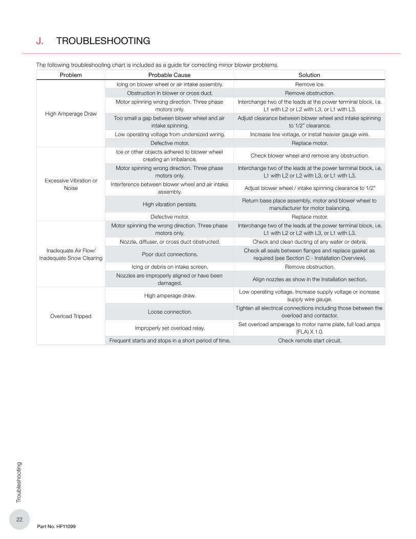
The following troubleshooting chart is included as a guide for correcting minor blower problems.
Problem Probable Cause Solution
High Amperage Draw
Icing on blower wheel or air intake assembly. Remove ice.
Obstruction in blower or cross duct. Remove obstruction.
Motor spinning wrong direction. Three phase motors only.
Interchange two of the leads at the power terminal block, i.e. L1 with L2 or L2 with L3, or L1 with L3.
Too small a gap between blower wheel and air intake spinning.
Adjust clearance between blower wheel and intake spinning to 1/2” clearance.
Low operating voltage from undersized wiring. Increase line voltage, or install heavier gauge wire.
Defective motor. Replace motor.
Excessive Vibration or Noise
Ice or other objects adhered to blower wheel creating an imbalance.
Check blower wheel and remove any obstruction.
Motor spinning wrong direction. Three phase motors only.
Interchange two of the leads at the power terminal block, i.e. L1 with L2 or L2 with L3, or L1 with L3.
Interference between blower wheel and air intake assembly.
Adjust blower wheel / intake spinning clearance to 1/2”
High vibration persists.Return base place assembly, motor and blower wheel to
manufacturer for motor balancing.
Defective motor. Replace motor.
Inadequate Air Flow/Inadequate Snow Clearing
Motor spinning the wrong direction. Three phase motors only.
Interchange two of the leads at the power terminal block, i.e. L1 with L2 or L2 with L3, or L1 with L3.
Nozzle, diffuser, or cross duct obstructed. Check and clean ducting of any water or debris.
Poor duct connections.Check all seals between flanges and replace gasket as
required (see Section C - Installation Overview).
Icing or debris on intake screen. Remove obstruction.
Nozzles are improperly aligned or have been damaged.
Align nozzles as show in the Installation section.
Overload Tripped
High amperage draw.Low operating voltage. Increase supply voltage or increase
supply wire gauge.
Loose connection.Tighten all electrical connections including those between the
overload and contactor.
Improperly set overload relay.Set overload amperage to motor name plate, full load amps
(FLA) X 1.0.
Frequent starts and stops in a short period of time. Check remote start circuit.
2323Part No. HF11099
Parts
K. PARTS
To ensure accurate part selection, have the model and serial number when placing an order.
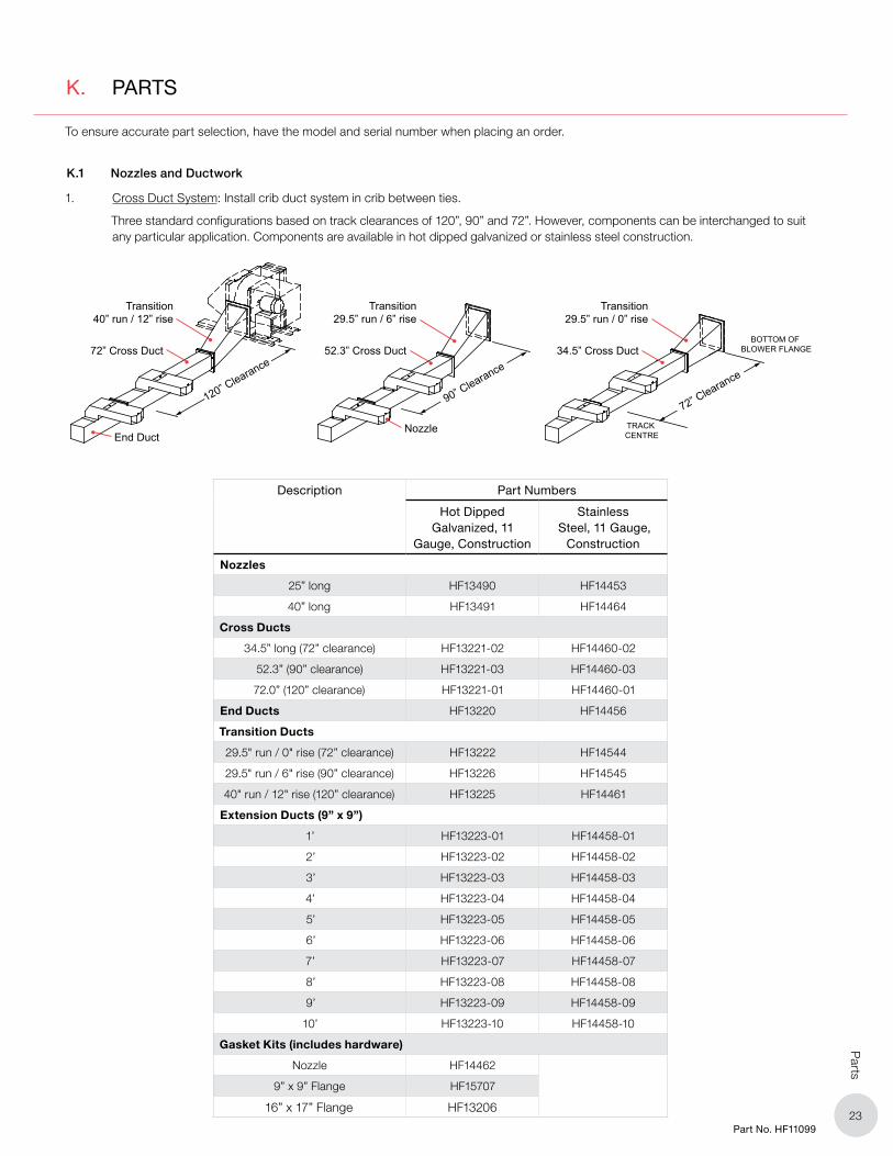
K.1 Nozzles and Ductwork
1. Cross Duct System: Install crib duct system in crib between ties.
Three standard configurations based on track clearances of 120”, 90” and 72”. However, components can be interchanged to suit any particular application. Components are available in hot dipped galvanized or stainless steel construction.
Description Part Numbers
Hot Dipped Galvanized, 11
Gauge, Construction
Stainless Steel, 11 Gauge,
Construction
Nozzles
25” long HF13490 HF14453
40” long HF13491 HF14464
Cross Ducts
34.5” long (72” clearance) HF13221-02 HF14460-02
52.3” (90” clearance) HF13221-03 HF14460-03
72.0” (120” clearance) HF13221-01 HF14460-01
End Ducts HF13220 HF14456
Transition Ducts
29.5" run / 0" rise (72” clearance) HF13222 HF14544
29.5" run / 6" rise (90” clearance) HF13226 HF14545
40" run / 12" rise (120” clearance) HF13225 HF14461
Extension Ducts (9” x 9”)
1’ HF13223-01 HF14458-01
2’ HF13223-02 HF14458-02
3’ HF13223-03 HF14458-03
4’ HF13223-04 HF14458-04
5’ HF13223-05 HF14458-05
6’ HF13223-06 HF14458-06
7’ HF13223-07 HF14458-07
8’ HF13223-08 HF14458-08
9’ HF13223-09 HF14458-09
10’ HF13223-10 HF14458-10
Gasket Kits (includes hardware)
Nozzle HF14462
9” x 9” Flange HF15707
16” x 17” Flange HF13206
Transition40” run / 12” rise
72” Cross Duct
120” Clearance
Transition29.5” run / 6” rise
52.3” Cross Duct
Nozzle
90” Clearance
End Duct
Transition29.5” run / 0” rise
34.5” Cross DuctBOTTOM OF
BLOWER FLANGE
TRACK CENTRE
72” Clearance

2424Part No. HF11099
Par
ts
2. Tie Duct System

2525Part No. HF11099
Parts
K.2 Blower Systems - Fastrax® HAC Series
K.3 Blower Systems - Fastrax® QHAC Series

2626Part No. HF11099
Par
ts
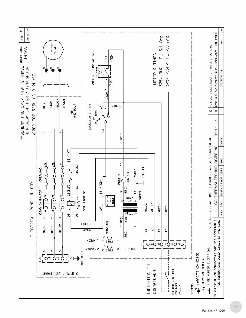
K.4 Electrical Components
240V Single Phase & 208V Three Phase

2727Part No. HF11099
Parts
460V & 575V Three Phase

PLEASE ADHERE TO INSTRUCTIONS IN THIS MANUAL
Failure to do so may be dangerous and may void certain provisions
of your warranty.
For further assistance, please call 1.855.244.3128
WARRANTY: Under normal use the Company warrants to the purchaser that defects in material or workmanship will be repaired or replaced without charge for a period of 84 months on SwitchBlade® heaters, 60 months on control panels, and 12 months on all other Fastrax® products, from date of shipment. Any claim for warranty must be reported to
the sales office where the product was purchased for authorized
repair or replacement within the contract terms.
Subject to State or Provincial law to the contrary, the Company
will not be responsible for any expense for installation, removal
from service, transportation, or damages of any type whatsoever,
including damages arising from lack of use, business interruptions,
or incidental or consequential damages.
The Company cannot anticipate or control the conditions of
product usage and therefore accepts no responsibility for the
safe application and suitability of its products when used alone or
in combination with other products. Tests for the safe application
and suitability of the products are the sole responsibility of the
user.
This warranty will be void if, in the judgment of the Company, the
damage, failure or defect is the result of:
• Vibration, radiation, erosion, corrosion, process
contamination, abnormal process conditions, temperature
and pressures, unusual surges or pulsation, fouling, ordinary
wear and tear, lack of maintenance, incorrectly applied
utilities such as voltage, air, gas, water, and others or any
combination of the aforementioned causes not specifically
allowed for in the design conditions
• Or, any act or omission by the Purchaser, its agents,
servants or independent contractors which for greater
certainty, but not so as to limit the generality of the
foregoing, includes physical, chemical or mechanical
abuse, accident, improper installation of the product,
improper storage and handling of the product, improper
application or the misalignment of parts.
No warranty applies to paint finishes except for manufacturing
defects apparent within 30 days from the date of installation.
The Company neither assumes nor authorizes any person to
assume for it any other obligation or liability in connection with the
product(s).
The Purchaser agrees that all warranty work required after the
initial commissioning of the product will be provided only if the
Company has been paid by the Purchaser in full accordance with
the terms and conditions of the contract.
The Purchaser agrees that the Company makes no warranty or
guarantee, express, implied or statutory, (including any warranty
of merchantability or warranty of fitness for a particular purpose)
written or oral, of the Article or incidental labour, except as is
expressed or contained in the agreement herein.
LIABILITY: Technical data contained in the catalog or on
the website is subject to change without notice. The Company
reserves the right to make dimensional and other design changes
as required. The Purchaser acknowledges the Company shall
not be obligated to modify those articles manufactured before
the formulation of the changes in design or improvements of the
products by the Company.
The Company shall not be liable to compensate or indemnify
the Purchaser, end user or any other party against any actions,
claims, liabilities, injury, loss, loss of use, loss of business,
damages, indirect or consequential damages, demands,
penalties, fines, expenses (including legal expenses), costs,
obligations and causes of action of any kind arising wholly or
partly from negligence or omission of the user or the misuse,
incorrect application, unsafe application, incorrect storage and
handling, incorrect installation, lack of maintenance, improper
maintenance or improper operation of products furnished by the
Company.
1500 W. Campus DriveLittleton, CO 80120 USA
1-855-244-31281-303-979-7339F 303-979-7350