Embed Size (px)
Citation preview

Mechanics and Mechanical EngineeringVol. 20, No. 1 (2016) 5–13c⃝ Lodz University of Technology
Fatigue Analysis of Automative Steering Knucle
S. Madhusudhanan
Department of Mechanical EngineeringDr.Mahalingam College of Engineering and Technology
Pollachi Tamilnadu, [email protected]
K. Arun KumarV. Praveen Kumar
T. Mahendran
Department of Mechanical EngineeringV.S.B Engineering collegeKarur, Tamilnadu, [email protected]@gmail.com
Received (22 December 2015)Revised (16 January 2016)Accepted (24 January 2016)
Steering knuckle plays a vital role in automobile which connects the suspension, steeringpart, wheel hub and brake to the chassis. During its working, it subjected to variousloading conditions. so, it requires high accuracy,, quality, and durability. The maintheme of this work is to access the fatigue performance of a steering knuckle. This canbe performed by a detailed load analysis. Therefore, this study requires two steps. Firstpart of the study involves modeling of the steering knuckle with the design parametersusing the latest modeling software CATIA and the second part involves in fatigue analysisusing ANSYS WORKBENCH. This provides us to improve the overall knowledge aboutthe component.
Keywords: Steering knuckle, static analysis, fatigue analysis.
1. Introduction
In your vehicle the joint that allows the steering arm to turn the front wheels calledsteering knuckle. The forces applied on this component are of cyclic nature asthe steering arm is turned to maneuver the vehicle to the left or to the right andto the centre again. The linking parts of the steering system and the suspensionsystem have a direct impact on the performance of the vehicle’s ride, durability,and steerability. So, the performance of these parts is directly compared to thequality of the vehicle. For this purpose, the strength of the knuckle under the
6 Madhusudhanan, S., Arun Kumar, K., Praveen Kumar, V. and Mahendran, T.
maximum service loads is calculated and the fatigue life is analyzed. Under thesame condition, the strain order formation is also calculated and it is verified thatthis value is within the allowable value.
2. Material testing
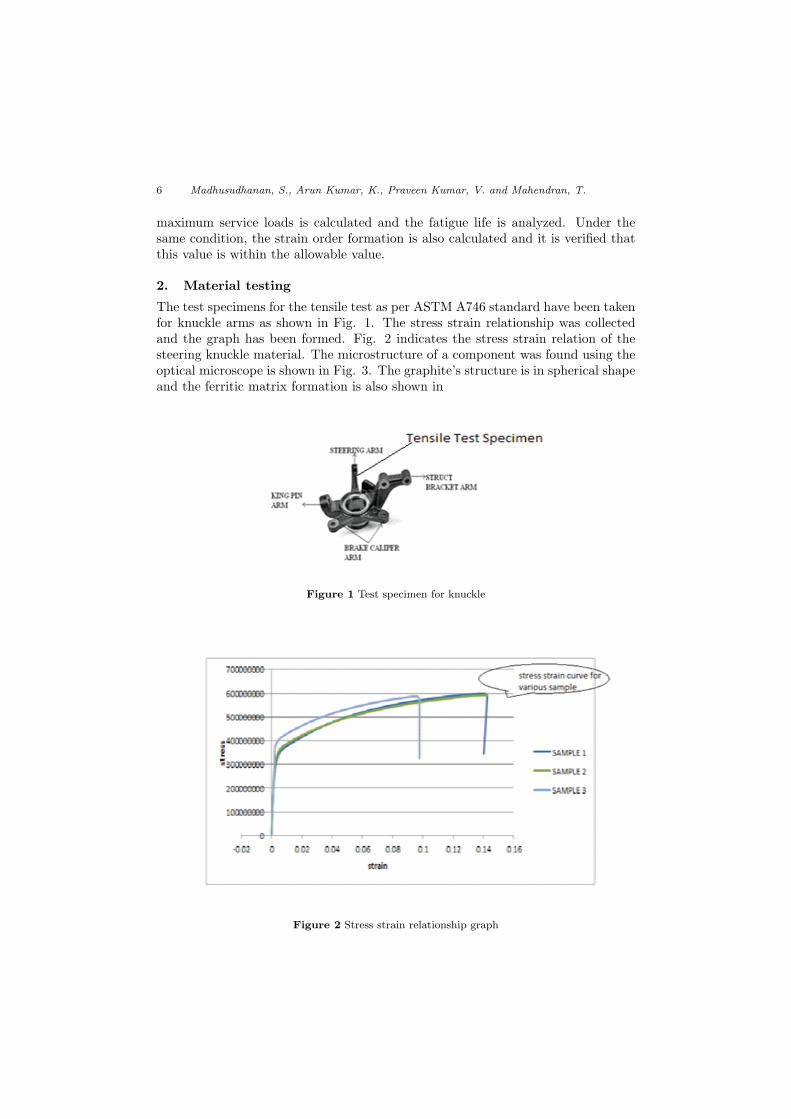
The test specimens for the tensile test as per ASTM A746 standard have been takenfor knuckle arms as shown in Fig. 1. The stress strain relationship was collectedand the graph has been formed. Fig. 2 indicates the stress strain relation of thesteering knuckle material. The microstructure of a component was found using theoptical microscope is shown in Fig. 3. The graphite’s structure is in spherical shapeand the ferritic matrix formation is also shown in
Figure 1 Test specimen for knuckle
Figure 2 Stress strain relationship graph

Fatigue Analysis of Automative Steering Knucle 7
Figure 3 Microstructure of ferrite matrix – SG iron knuckle
3. Design Methodology
Steps Involved in Methodology is given below:
Step 1: Modeling of steering knuckle using 3D modeling software.
Step 2: Finite element modeling of the steering knuckle.
Step 3: Analysis of steering knuckle using ANSYS software:
– element selection,
– discretization,
– mesh generation.
Step 4: Finite element static analysis.
Step 5: Fatigue analysis
4. Finite element modeling
The structures of steering knuckle parts are shown in the Fig. 1; modeling ofthe component was created using CATIA. Here element type used was tetrahedralelement with 70323 nodes and 41067 elements. The boundary condition and meshedmodel is shown in Fig. 4 and Fig. 5.
5. Analysis
The static analysis was done by using ANSYS WORKBENCH metric converterProductID15. In15. In the preprocessor, the element type solid 186 was chosenfor the knuckle component. Because of elasto–plastic nature of material, the resultvaries with linear analysis to non–linear analysis.

8 Madhusudhanan, S., Arun Kumar, K., Praveen Kumar, V. and Mahendran, T.
Figure 4 Boundary conditions
Figure 5 Meshed model of steering knuckle
So in this analysis, material nonlinearity was considered and the average stress strainrelation curve data obtained from tensile test is given as input to the software.
The material properties Young’s modulus (E) is 1.6E5 N/mm2 and the Poissonratio is 0.28. In ANSYS, the Newton–Raphson algorithm was chosen for non–linearanalysis.
[K]{u} = {F}

Fatigue Analysis of Automative Steering Knucle 9
Regarding the fatigue analysis, the knuckle arm was analyzed by means of a curvebased on the strain–life method. The various stain life parameter called strengthexponent, strength co efficient, ductility exponent, ductility coefficient and strainhardening parameter were calculated. The knuckle was analyzed for about 106
cycles. In the strain–life approach, the values of stress and strain at the criticallocation were used to find strain life is given below equation.
δ ∈2
=σ′f
E(2Nf )
b+ σ′
f (2Nf )c
Morrow stain life theory of approach states that increase in effect of mean stressleads to decrease the elastic strain amplitude. Based on the morrow parameterwhich considers the mean stress effect equation is given below.
δ ∈2
=σ′f − σm
E(2Nf )
b+ σ′
f (2Nf )c
The fatigue life of component can be obtained using Basquin equation with the helpof material properties.
σNf = σ′f (2Nf )
b
The factor of safety can be obtained by below equation
fos =1
σa
σ−1+ σm
σu
Figure 6 Von Mises stress

10 Madhusudhanan, S., Arun Kumar, K., Praveen Kumar, V. and Mahendran, T.
Figure 7 Elastic strain
Figure 8 Fatigue life

Fatigue Analysis of Automative Steering Knucle 11
Figure 9 Fatigue damage
Figure 10 Safety factor
6. Results and discussion
6.1. Virtual analysis results
The maximum stress and maximum strain are shown in Fig. 6 and Fig. 7 forthe static analysis. The maximum stress concentrating area and maximum strainaffecting area are shown in rounded region. The tends to withstand about 598 MPaof stress and strain of about 0.003 which is shown.
The fatigue properties of the analyzed result are shown in below Figs 8–11.These say that the component having load factor below 0.5 exhibit good fatiguestrength.
12 Madhusudhanan, S., Arun Kumar, K., Praveen Kumar, V. and Mahendran, T.
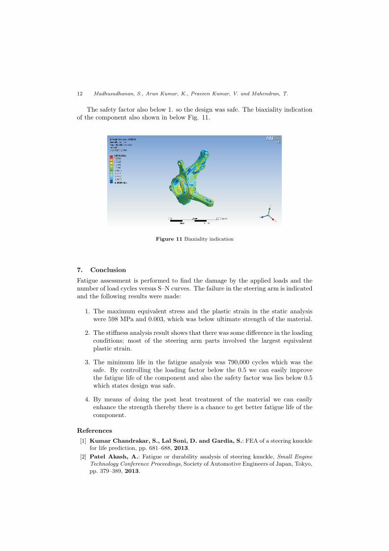
The safety factor also below 1. so the design was safe. The biaxiality indicationof the component also shown in below Fig. 11.
Figure 11 Biaxiality indication
7. Conclusion
Fatigue assessment is performed to find the damage by the applied loads and thenumber of load cycles versus S–N curves. The failure in the steering arm is indicatedand the following results were made:
1. The maximum equivalent stress and the plastic strain in the static analysiswere 598 MPa and 0.003, which was below ultimate strength of the material.
2. The stiffness analysis result shows that there was some difference in the loadingconditions; most of the steering arm parts involved the largest equivalentplastic strain.
3. The minimum life in the fatigue analysis was 790,000 cycles which was thesafe. By controlling the loading factor below the 0.5 we can easily improvethe fatigue life of the component and also the safety factor was lies below 0.5which states design was safe.
4. By means of doing the post heat treatment of the material we can easilyenhance the strength thereby there is a chance to get better fatigue life of thecomponent.
References
[1] Kumar Chandrakar, S., Lal Soni, D. and Gardia, S.: FEA of a steering knucklefor life prediction, pp. 681–688, 2013.
[2] Patel Akash, A.: Fatigue or durability analysis of steering knuckle, Small EngineTechnology Conference Proceedings, Society of Automotive Engineers of Japan, Tokyo,pp. 379–389, 2013.
Fatigue Analysis of Automative Steering Knucle 13
[3] Jhala, R. L. and Kothari, K. D.: Component fatigue behavior and life predictionof a steering knuckle using FEA, pp. 646–657, 2009.
[4] Dumber, P.O. and Kweon, S.S.: Stress Analysis On Steering Knuckle Of TheAutomobile Steering System, Materials and Design, Vol. 28(4), 1198–1210, 2014.
[5] Kamal, M., Mustafizur Rahman, M. and Sani, M.S.M.: Application multibodySimulation For Fatigue Life Estimation, Vol. 7, pp. 912–923, 2013.
[6] www.sciencedirect.com
[7] www.ijret.com
NomenclatureK – stiffness matrix of the materialu – displacement matrixF – applied force in KN∆ε – strain amplitudeE – young’s modulus in MPaNf – No of cycles to failureb – fatigue strength exponentc – ductility exponentσNf
– fatigue life