Embed Size (px)
Citation preview
Fatigue and Dynamic LoadingFatigue and Dynamic Loading
1
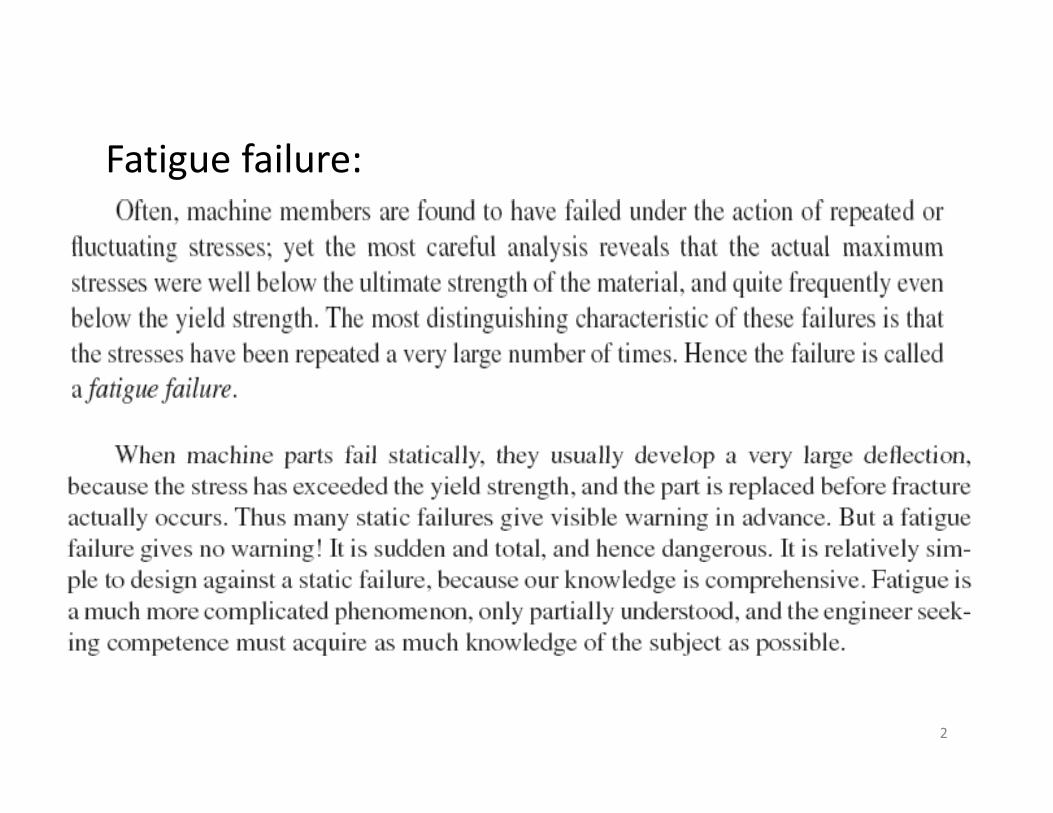
F ti f ilFatigue failure:
2
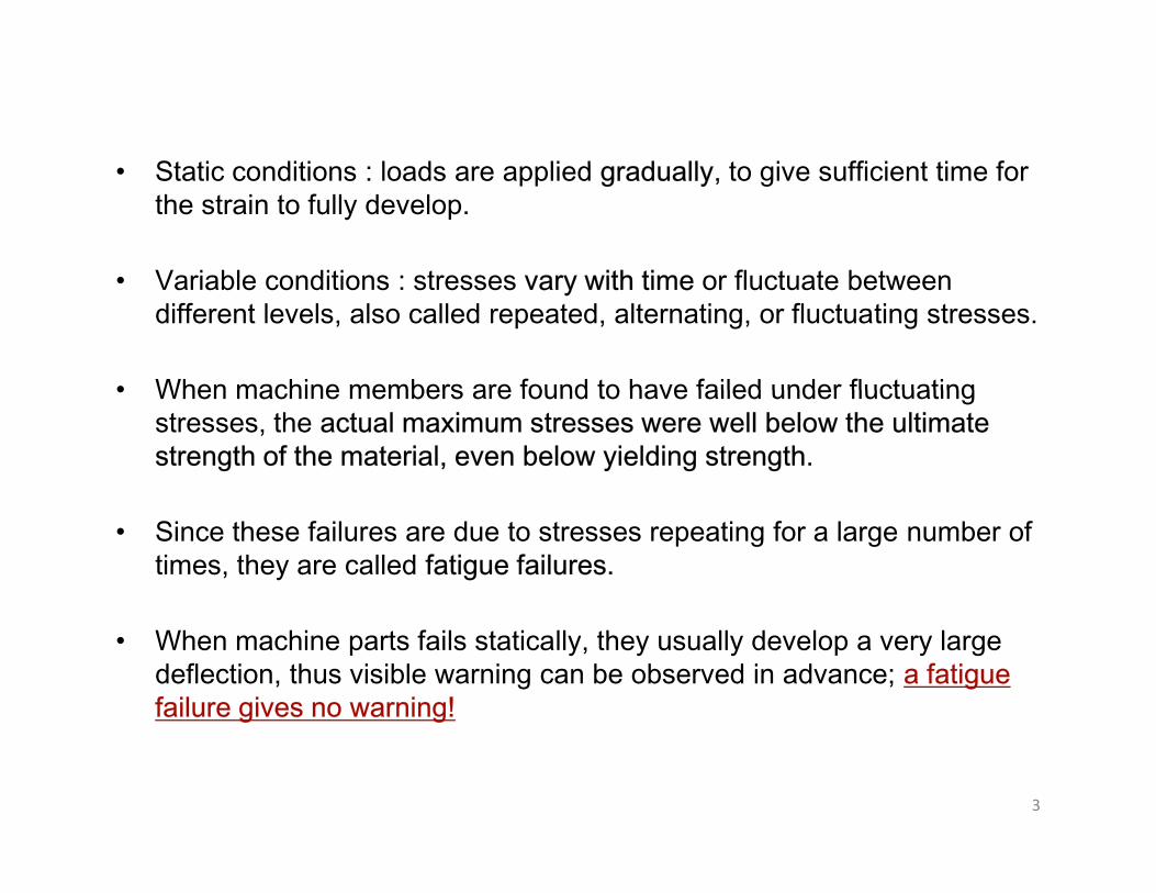
St ti diti l d li d d ll t i ffi i t ti f• Static conditions : loads are applied gradually, to give sufficient time for the strain to fully develop.
• Variable conditions : stresses vary with time or fluctuate between• Variable conditions : stresses vary with time or fluctuate between different levels, also called repeated, alternating, or fluctuating stresses.
• When machine members are found to have failed under fluctuating• When machine members are found to have failed under fluctuating stresses, the actual maximum stresses were well below the ultimate strength of the material, even below yielding strength.
• Since these failures are due to stresses repeating for a large number of times, they are called fatigue failures.
• When machine parts fails statically, they usually develop a very large deflection, thus visible warning can be observed in advance; a fatigue failure gives no warning!
3
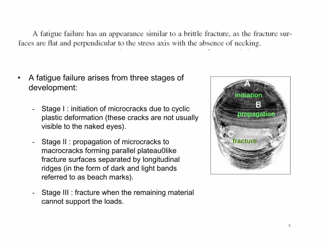
• A fatigue failure arises from three stages of
initiation
• A fatigue failure arises from three stages of development:
- Stage I : initiation of microcracks due to cyclicpropagation
fracture
- Stage I : initiation of microcracks due to cyclic plastic deformation (these cracks are not usually visible to the naked eyes).
Stage II : propagation of microcracks to fracture- Stage II : propagation of microcracks to macrocracks forming parallel plateau0like fracture surfaces separated by longitudinal ridges (in the form of dark and light bands referred to as beach marks).
- Stage III : fracture when the remaining material cannot support the loads.
4
pp
5
6
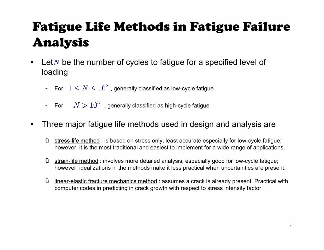
Fatigue Life Methods in Fatigue Failure AnalysisAnalysis• Let be the number of cycles to fatigue for a specified level of
loading
- For , generally classified as low-cycle fatigue
- For , generally classified as high-cycle fatigue
• Three major fatigue life methods used in design and analysis are
ü stress-life method : is based on stress only least accurate especially for low-cycle fatigue;ü stress-life method : is based on stress only, least accurate especially for low-cycle fatigue; however, it is the most traditional and easiest to implement for a wide range of applications.
ü strain-life method : involves more detailed analysis, especially good for low-cycle fatigue; however, idealizations in the methods make it less practical when uncertainties are present.
ü linear-elastic fracture mechanics method : assumes a crack is already present. Practical with computer codes in predicting in crack growth with respect to stress intensity factor
7
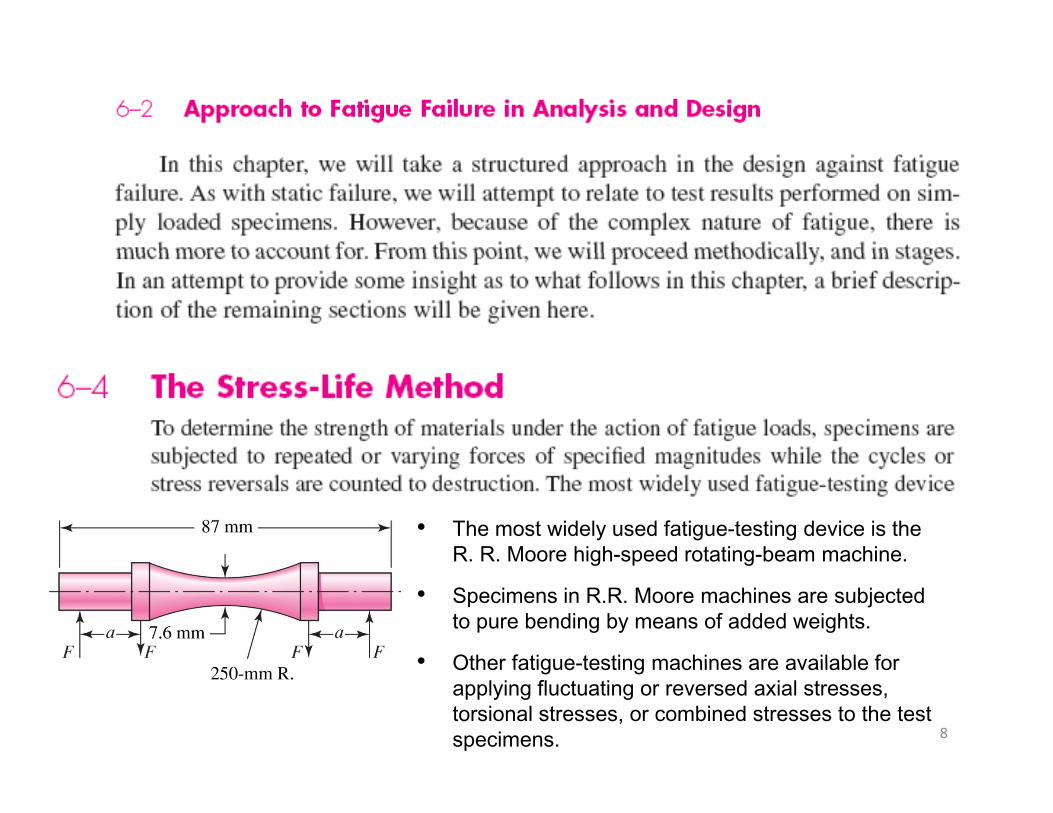
• The most widely used fatigue-testing device is the R. R. Moore high-speed rotating-beam machine.R. R. Moore high speed rotating beam machine.
• Specimens in R.R. Moore machines are subjected to pure bending by means of added weights.
• Other fatigue testing machines are available for
8
• Other fatigue-testing machines are available for applying fluctuating or reversed axial stresses, torsional stresses, or combined stresses to the test specimens.
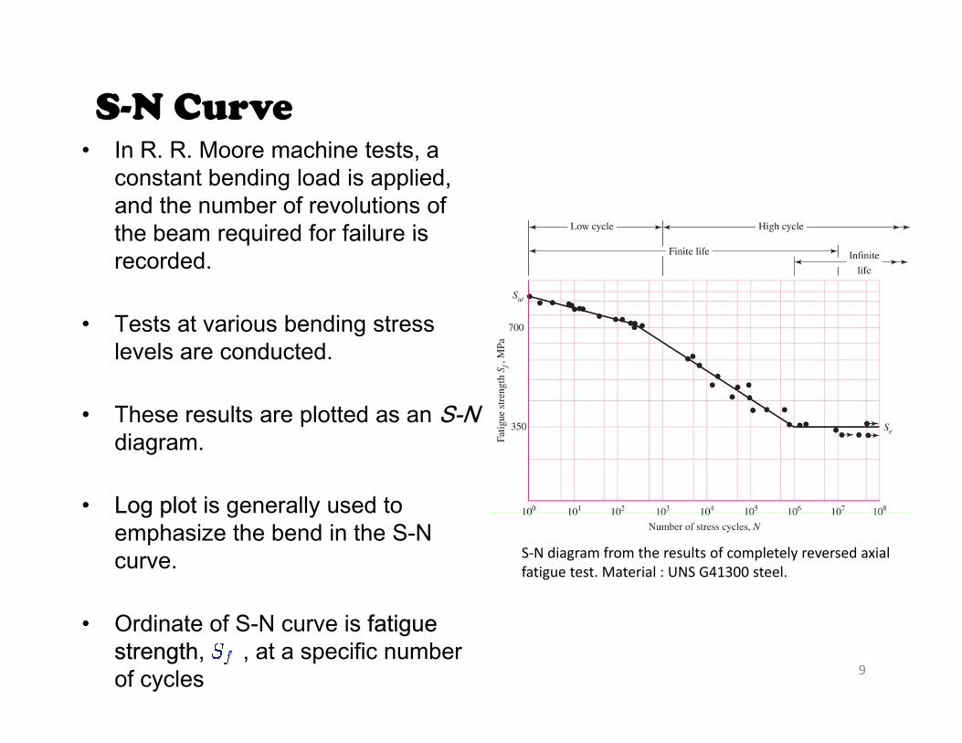
S-N Curve• In R. R. Moore machine tests, a
constant bending load is applied, and the number of revolutions of the beam required for failure isthe beam required for failure is recorded.
• Tests at various bending stress• Tests at various bending stress levels are conducted.
• These results are plotted as an S-NThese results are plotted as an S Ndiagram.
• Log plot is generally used toLog plot is generally used to emphasize the bend in the S-N curve. S‐N diagram from the results of completely reversed axial
fatigue test. Material : UNS G41300 steel.
9
• Ordinate of S-N curve is fatigue strength, , at a specific number of cycles
Characteristics of S-N Curves for Metals
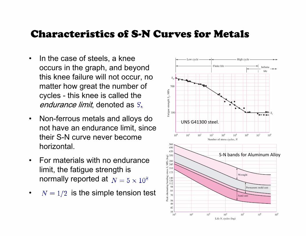
• In the case of steels, a knee occurs in the graph, and beyond this knee failure will not occur, no matter how great the number of cycles - this knee is called the end rance limit denoted asendurance limit, denoted as
• Non-ferrous metals and alloys do not have an endurance limit, since
UNS G41300 steel.
their S-N curve never become horizontal.
• For materials with no enduranceS‐N bands for Aluminum Alloy
For materials with no endurance limit, the fatigue strength is normally reported at
• is the simple tension test
10
• is the simple tension test
11
12
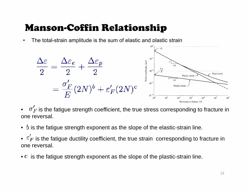
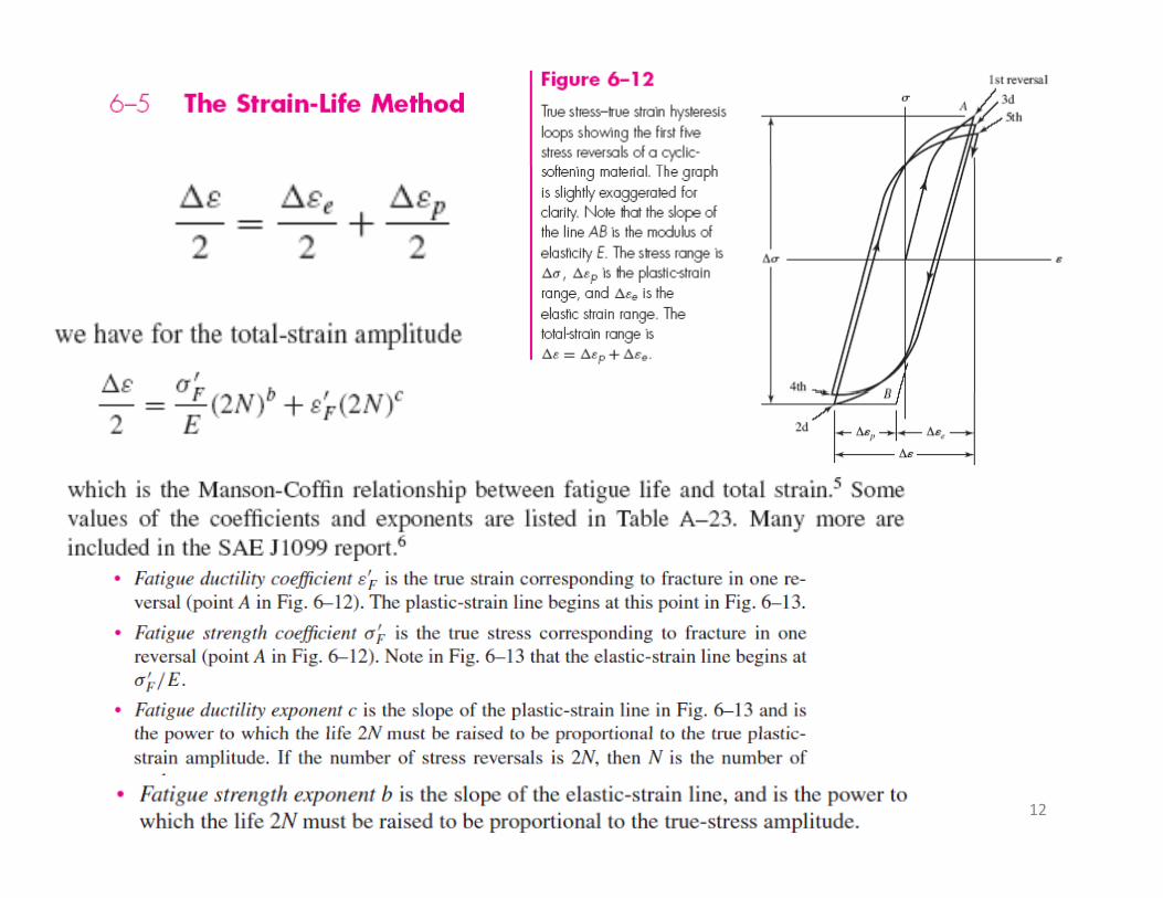
Manson-Coffin Relationship • The total-strain amplitude is the sum of elastic and plastic strain
i th f ti t th ffi i t th t t di t f t i• is the fatigue strength coefficient, the true stress corresponding to fracture in one reversal.
• is the fatigue strength exponent as the slope of the elastic-strain line.
• is the fatigue ductility coefficient, the true strain corresponding to fracture in one reversal.
• is the fatigue strength exponent as the slope of the plastic strain line
13
• is the fatigue strength exponent as the slope of the plastic-strain line.
14
15
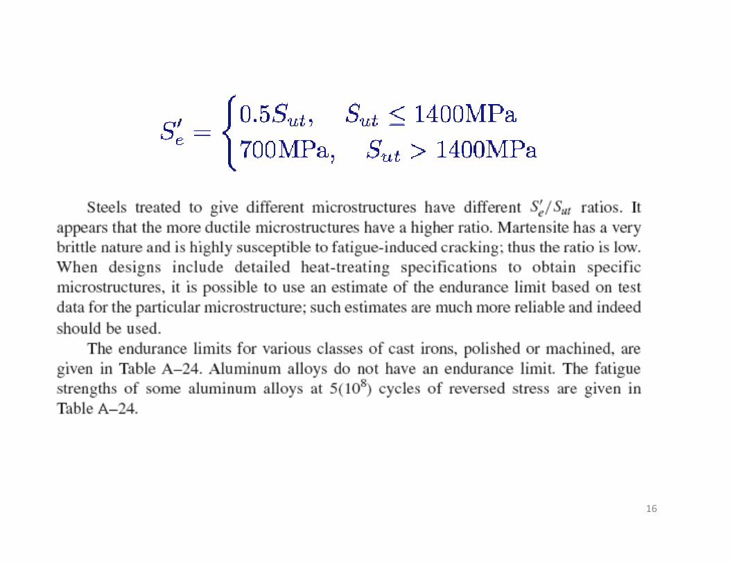
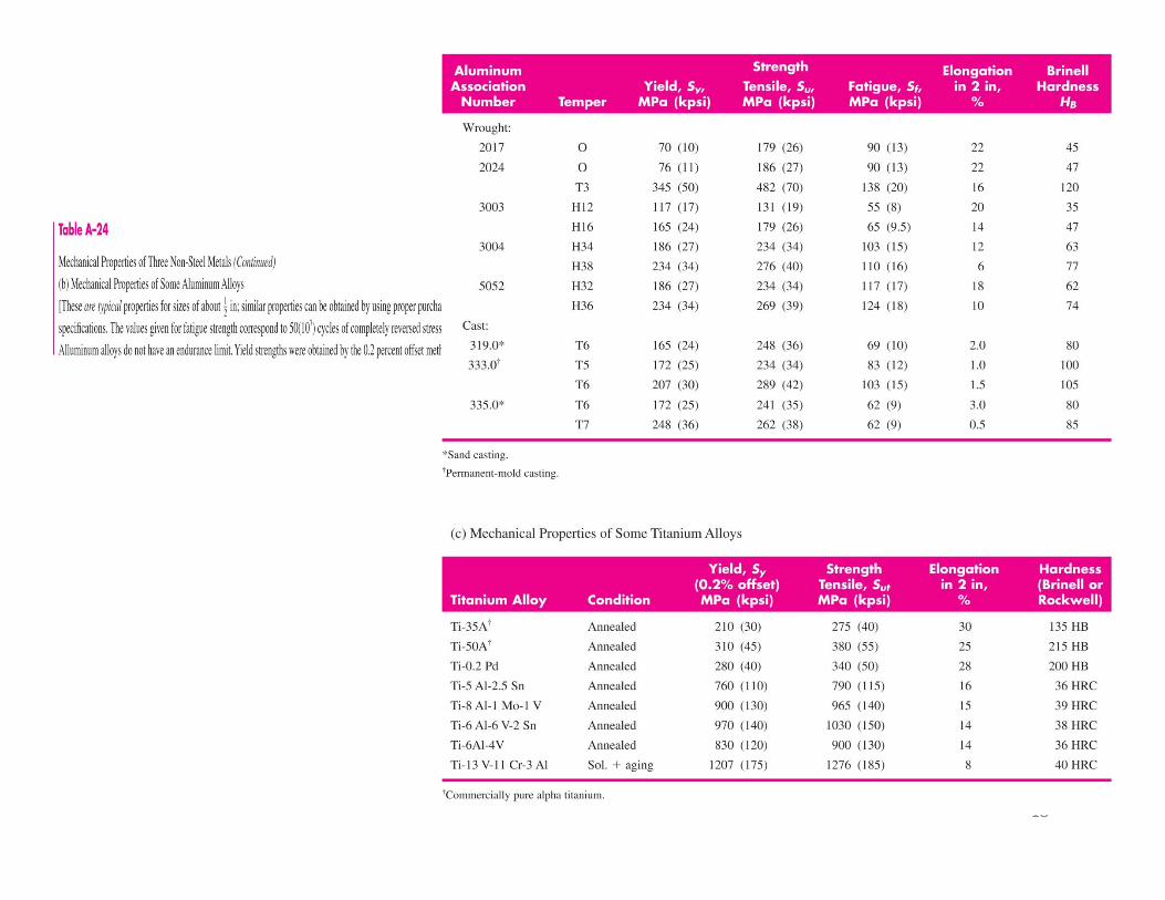
16
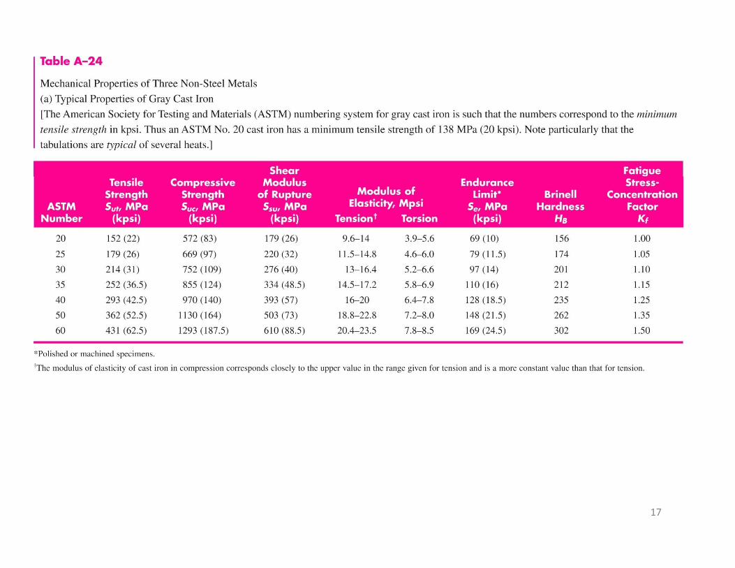
17
18
Fatigue Strength : Basics
• Low-cycle fatigue considers the range from N=1 to about 1000 cyclesto about 1000 cycles.
• In this region, the fatigue strength is only slightly smaller than the tensile strength .slightly smaller than the tensile strength .
• High-cycle fatigue domain extends from 103 to the endurance limit life (106 to 107 cycles). ( y )
• Experience has shown that high-cycle fatigue data are rectified by a logarithmic transform to y gboth stress and cycles-to-failure.
1919
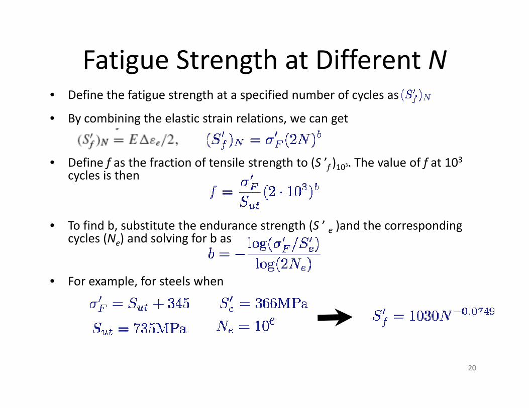
Fatigue Strength at Different N• Define the fatigue strength at a specified number of cycles as
• By combining the elastic strain relations, we can get
• Define f as the fraction of tensile strength to (S ’f )103. The value of f at 103cycles is thencycles is then
• To find b, substitute the endurance strength (S ’ e )and the corresponding , g ( e ) p gcycles (Ne) and solving for b as
• For example for steels when• For example, for steels when
2020
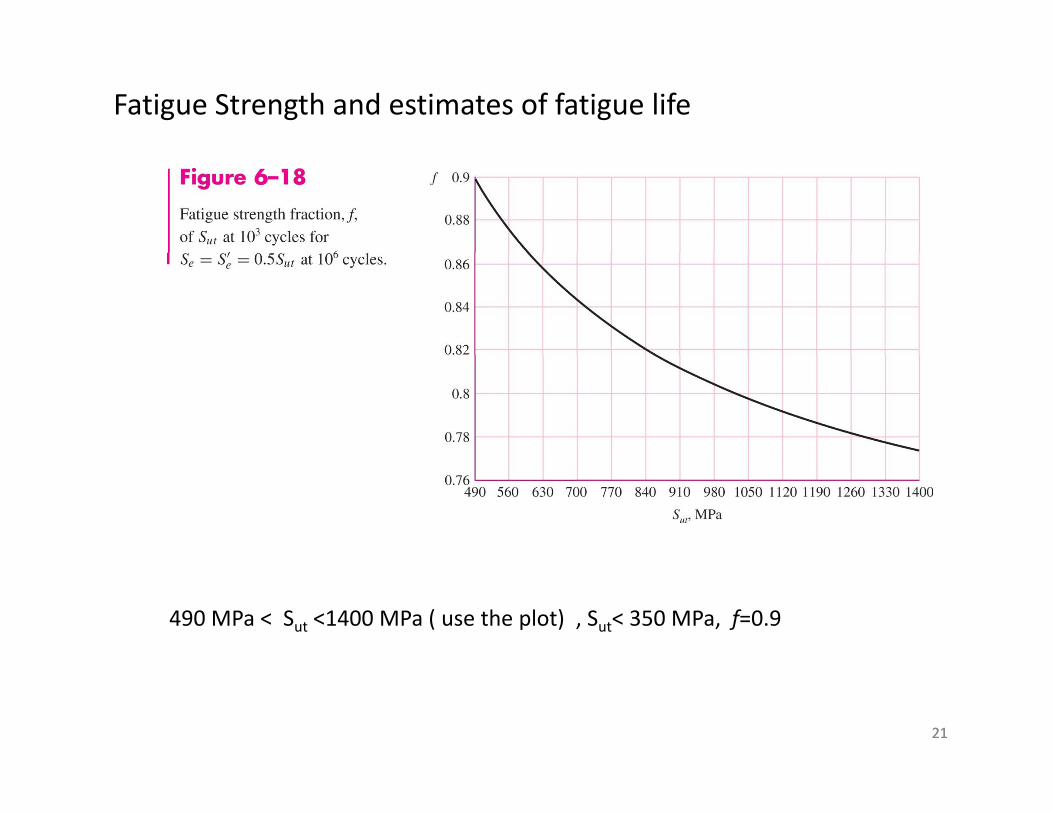
Fatigue Strength and estimates of fatigue life
490 MPa < Sut <1400 MPa ( use the plot) , Sut< 350 MPa, f=0.9
2121
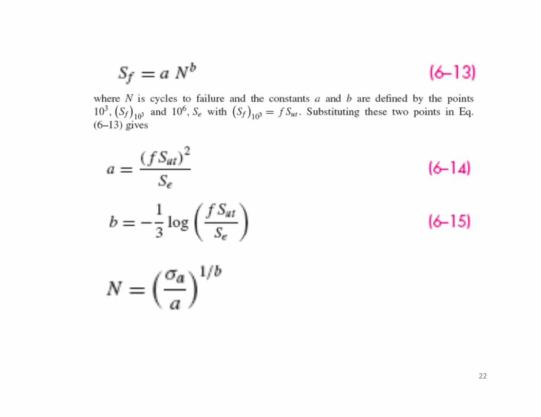
2222
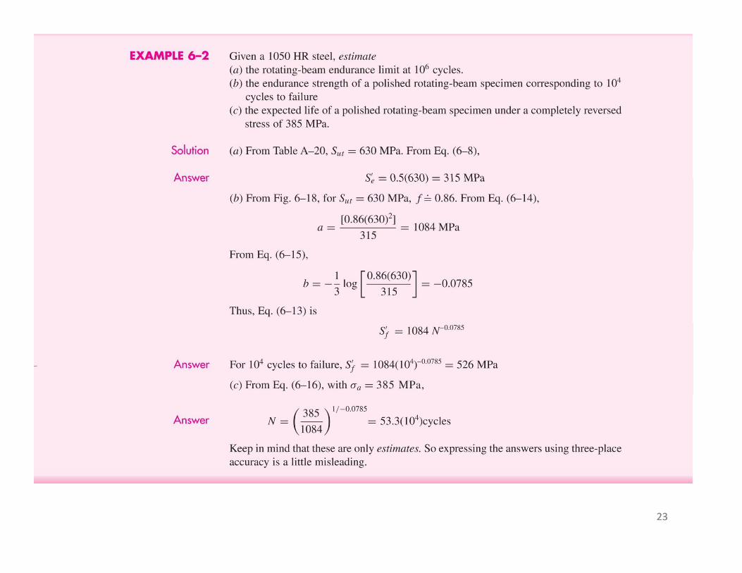
2323
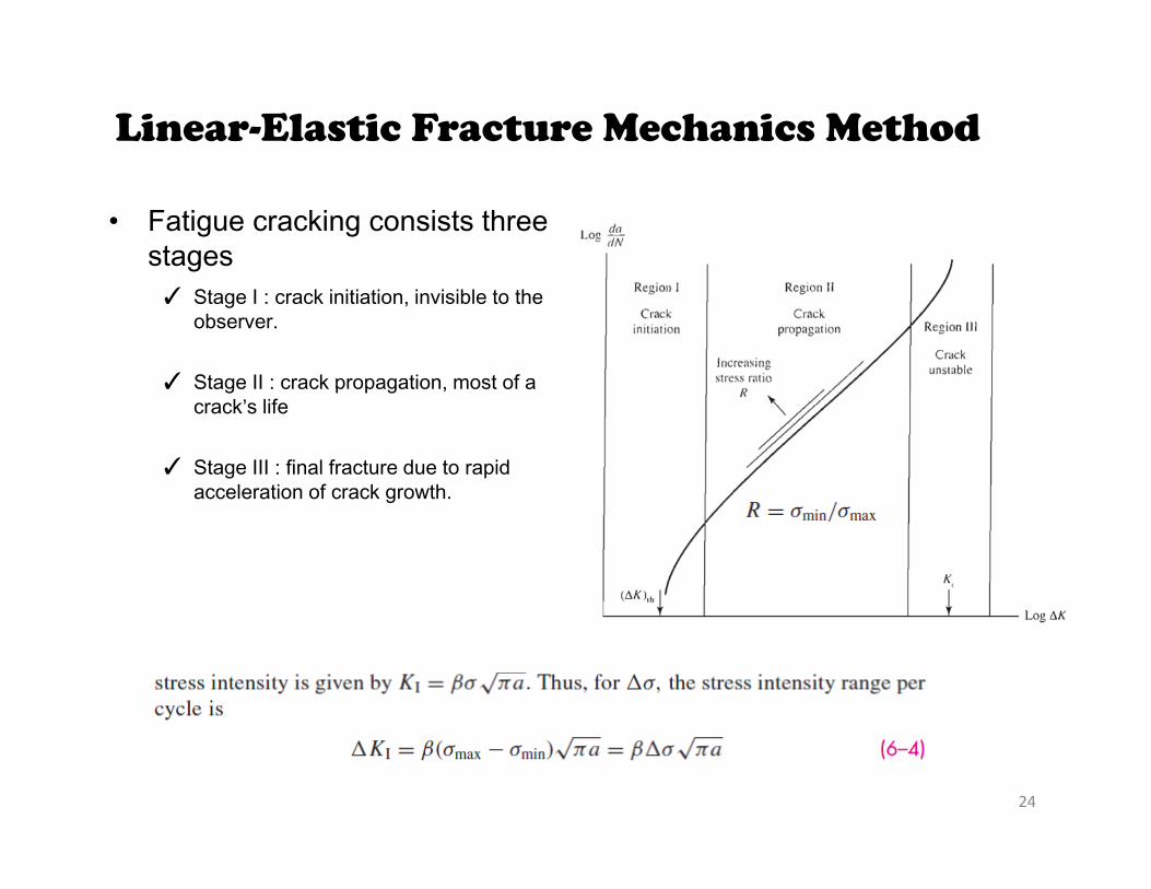
Linear-Elastic Fracture Mechanics Method
• Fatigue cracking consists three stages✓ Stage I : crack initiation, invisible to the
observer.
✓ Stage II : crack propagation, most of a✓ Stage II : crack propagation, most of a crack’s life
✓ Stage III : final fracture due to rapid acceleration of crack growth.g
24
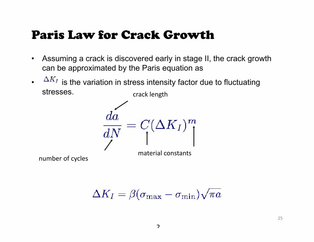
Paris Law for Crack Growth
• Assuming a crack is discovered early in stage II, the crack growth can be approximated by the Paris equation as
• is the variation in stress intensity factor due to fluctuating stresses. crack length
number of cyclesmaterial constants
25
2
26
27
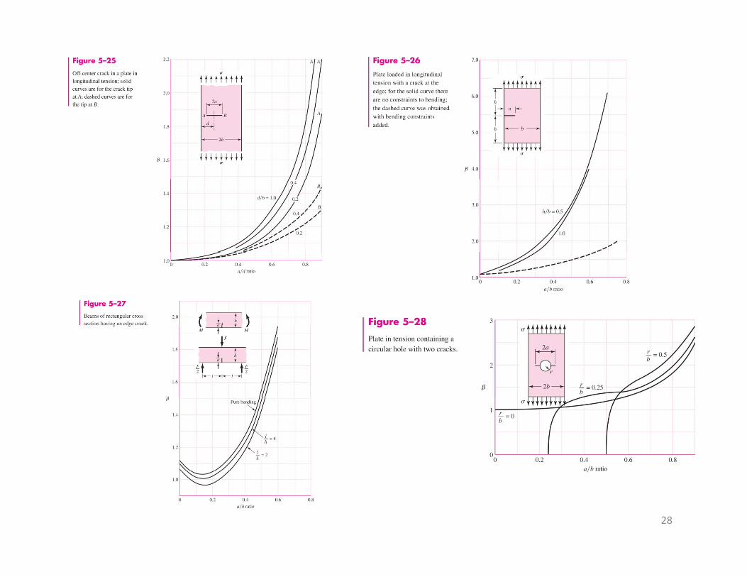
28
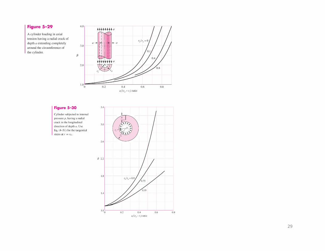
29
30
31