Embed Size (px)
Citation preview
177
Babcock International Group | Africa DivisionNtuthuko Generation
1 Osborne Lane | Bedfordview | 2007PO Box 4561 | Johannesburg | 2000 | South Africa
Tel +27 (0)11 601 1000www.babcock.co.za
FATIGUE ASSESSMENT OF A BOILER STEAM DRUMINTRODUCTION
This work addresses fatigue assessment of a 200MW boiler steam drum. It was done in the context of a life extension study to determine if the boiler could be used until 2035. Given the high cost of replacing the steam drum, it is very important to understand its structural integrity. The main concern with regard to drum integrity is widespread fatigue cracking of large nozzle welds or seam welds. Fatigue in the steam drum is primarily caused by the combined action of pressure and temperature cycling.
The effects of thermal cycling are always a concern, but also difficult to quantify by means of hand calculations. This contributes to uncertainty regarding the drum’s integrity. Small cracks can usually be ground out and is consequently not a major risk. However, in the event of a large crack in the drum, the client will be forced to do a high risk weld repair. Therefore, fatigue assessment was focused on features of which failure would lead to high-risk repairs, e.g. downcomer nozzle welds and seam welds.
DESCRIPTION OF THE PLANT
The boiler under consideration is a Babcock & Wilcox El-Paso unit that was commissioned around 1970. It burns pulverized coal and it is rated at 200MW. Since commissioning, the unit has done approximately 300 000 turbine run hours.
Figure 1 shows an isometric view of the drum. It consists of a seam-welded cylindrical shell with spherical ends and is approximately 19m in overall length. It is supplied with water from the economiser and then supplies water to the furnace walls via the large downcomer nozzles at the bottom. Saturated water and steam are returned to the drum through a multitude of riser nozzles. Drum internals (cyclones and scrubbers) then separate the steam from water and steam exits at the saturated steam nozzles at the top of the drum, from where it travels to the superheaters.
Both the shell and heads are made of high-tensile steel. It is supported from a sling deck via two composite steel slings and bearing pads that are welded on the drum near the shell ends.
The shell has an inner diameter of approximately 1700mm and thickness of 65mm. The spherical heads are approximately 90mm thick and their inner diameters are equal to that of the drum, with thickness matching done on the OD of the spherical heads.
Figure 1: Sections of the steam drum chosen for FE analysis (shown highlighted).
LOADS ON THE DRUM
In view of a fatigue analysis of the drum, it is important to understand the loads experienced by the drum and how these cause stress cycles.
The loads on the steam drum are as follows:
• Pressure (12MPa).• Thermal stresses caused during start-up and shutdown
transients.• Weight loads (self-weight and equipment suspended from
downcomers).• Restrained thermal expansion of pipework connecting to the
drum.• Safety valve thrust loads.
(This will form part of a future project.)
FATIGUE ASSESSMENT METHOD
Throughout this work, the method of PD5500a was used to calculate and evaluate fatigue damage. The assessment was not aimed at calculating remaining life of the drum. Rather, the assessment was conducted in a conservative manner and consequently demonstrated that estimated fatigue damages were insignificant.
Given the complexity of geometry and loads, stresses were calculated using the finite element method. Processing of the stresses to derive stress ranges was done according to the prescriptions of PD5500. For unwelded material, the principal stress with the largest range was cycle counted; for weld toes, stress linearization was done according to the method of EN13445b in order to arrive at structural hot spot stresses which could be used for cycle counting. Since stress cycles turned out to be relatively simple, cycle counting was done by inspection.
aBritish Standards Institute, PD5500: Specification for unfired fusion welded pressure vessels, BSI, 2003.bBritish standards institute, EN13445: Unfired pressure vessels - design, 2009.
178
Babcock International Group | Africa DivisionNtuthuko Generation
1 Osborne Lane | Bedfordview | 2007PO Box 4561 | Johannesburg | 2000 | South Africa
Tel +27 (0)11 601 1000www.babcock.co.za
The client classifies the plant shutdown-start cycles according to the downtime before start-up into 5 different types, ranging from hot to cold starts. Rather than assessing each feature for every cycle type, a simple analysis was done upfront in order to determine the worst cycles for the main shell and for the drumheads. For a specific feature, it was then conservatively assumed that every cycle is of the worst kind. Based on historical averages, the total estimated number of cycles at 2035 will be 984, and we used this value throughout.
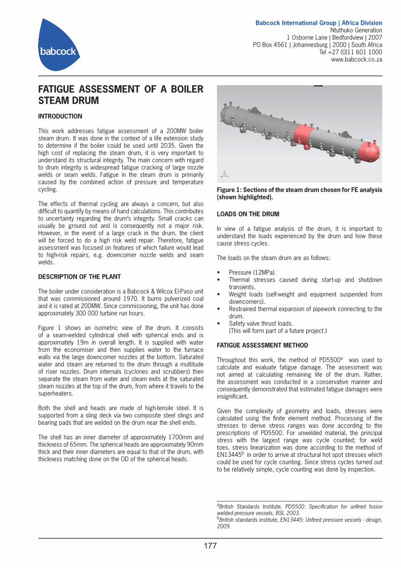
In keeping with a conservative assessment, fatigue damage calculations were based on design S-N data. S-N curves in PD5500 are two standard deviations below the mean, corresponding to 97.7% probability of survival. Several curves are given: one for unwelded material and then curves which correspond to various component classes. Each feature was therefore categorized and its stress ranges were evaluated against the appropriate curve.
Figure 2: PD5500 S-N Curves
Corrosion fatigue is not addressed quantitatively in PD5500. However, EN13445 prescribes limits on the stresses and stress ranges experienced by the magnetite layer on the water-touched part of the drum in order that corrosion fatigue may be limited.
Building a model that incorporates all detail features and running it for all cycle types would have resulted in too many calculations and enormous post-processing effort. In order to avoid this, we evaluated the importance of different effects in a few stages of analysis and then conducted a final analysis that only incorporated the necessary detail.
ANALYSIS STAGE 1: CLEAN DRUM
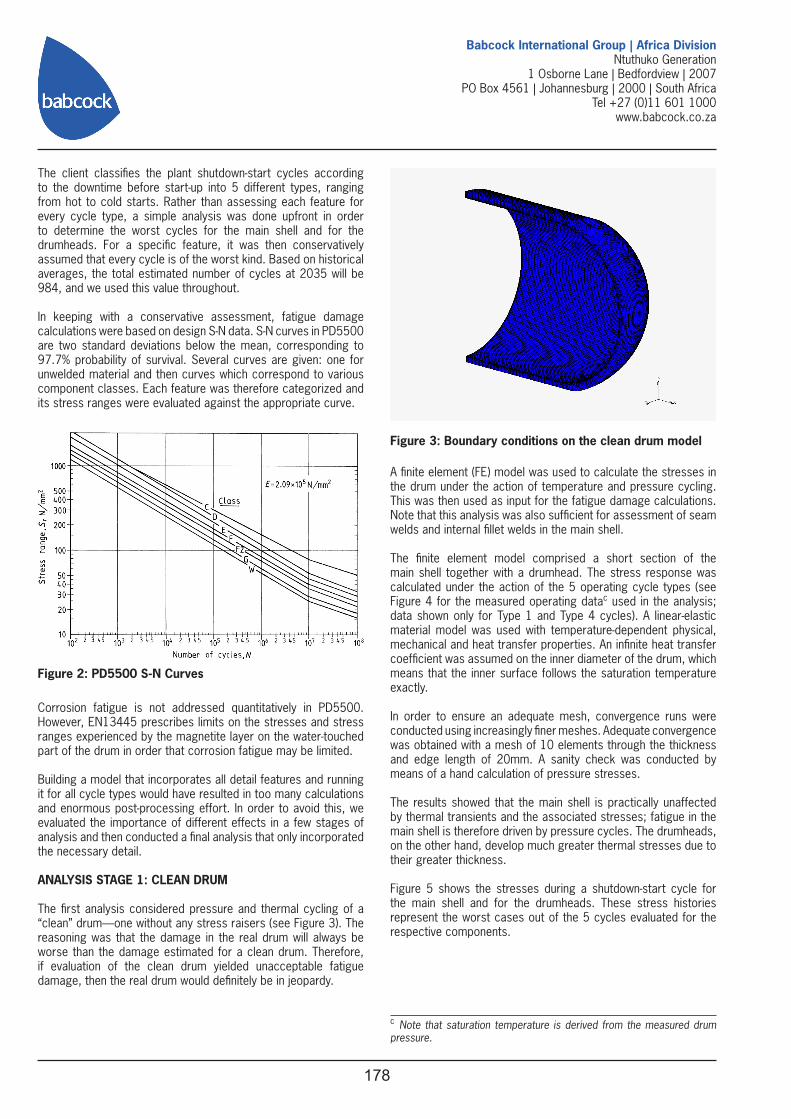
The first analysis considered pressure and thermal cycling of a “clean” drum—one without any stress raisers (see Figure 3). The reasoning was that the damage in the real drum will always be worse than the damage estimated for a clean drum. Therefore, if evaluation of the clean drum yielded unacceptable fatigue damage, then the real drum would definitely be in jeopardy.
Figure 3: Boundary conditions on the clean drum model
A finite element (FE) model was used to calculate the stresses in the drum under the action of temperature and pressure cycling. This was then used as input for the fatigue damage calculations. Note that this analysis was also sufficient for assessment of seam welds and internal fillet welds in the main shell.
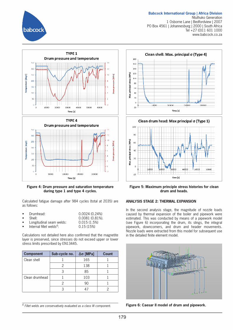
The finite element model comprised a short section of the main shell together with a drumhead. The stress response was calculated under the action of the 5 operating cycle types (see Figure 4 for the measured operating datac used in the analysis; data shown only for Type 1 and Type 4 cycles). A linear-elastic material model was used with temperature-dependent physical, mechanical and heat transfer properties. An infinite heat transfer coefficient was assumed on the inner diameter of the drum, which means that the inner surface follows the saturation temperature exactly.
In order to ensure an adequate mesh, convergence runs were conducted using increasingly finer meshes. Adequate convergence was obtained with a mesh of 10 elements through the thickness and edge length of 20mm. A sanity check was conducted by means of a hand calculation of pressure stresses.
The results showed that the main shell is practically unaffected by thermal transients and the associated stresses; fatigue in the main shell is therefore driven by pressure cycles. The drumheads, on the other hand, develop much greater thermal stresses due to their greater thickness.
Figure 5 shows the stresses during a shutdown-start cycle for the main shell and for the drumheads. These stress histories represent the worst cases out of the 5 cycles evaluated for the respective components.
c Note that saturation temperature is derived from the measured drum pressure.
179
Babcock International Group | Africa DivisionNtuthuko Generation
1 Osborne Lane | Bedfordview | 2007PO Box 4561 | Johannesburg | 2000 | South Africa
Tel +27 (0)11 601 1000www.babcock.co.za
Figure 4: Drum pressure and saturation temperature during type 1 and type 4 cycles.
Figure 5: Maximum principle stress histories for clean drum and heads.
Calculated fatigue damage after 984 cycles (total at 2035) are as follows:
• Drumhead: 0.0024 (0.24%)• Shell: 0.0081 (0.81%).• Longitudinal seam welds: 0.015 (1.5%)• Internal fillet weldsd: 0.15 (15%)
Calculations not detailed here also confirmed that the magnetite layer is preserved, since stresses do not exceed upper or lower stress limits prescribed by EN13445.
Component Sub-cycle no. Δσ [MPa] Count
Clean shell 1 165 1
2 138 1
3 85 1
Clean drumhead 1 103 1
2 90 1
3 47 2
d Fillet welds are conservatively evaluated as a class W component.
ANALYSIS STAGE 2: THERMAL EXPANSION
In the second analysis stage, the magnitude of nozzle loads caused by thermal expansion of the boiler and pipework were estimated. This was conducted by means of a pipework model (see Figure 6) incorporating the drum, its slings, the integral pipework, downcomers, and drum and header movements. Nozzle loads were extracted from this model for subsequent use in the detailed finite element model.
Figure 6: Caesar II model of drum and pipework.
180
Babcock International Group | Africa DivisionNtuthuko Generation
1 Osborne Lane | Bedfordview | 2007PO Box 4561 | Johannesburg | 2000 | South Africa
Tel +27 (0)11 601 1000www.babcock.co.za
Calculation of nozzle loads on the drum is not a trivial matter; it is a function of drum and piping layout, thermal expansion, stiffness of the pipework, and boiler movements. The boundary conditions of the pipework model are not straightforward. Nevertheless, a model was built consistent with anticipated plant behaviour.
In order to derive the expansion-related loads (EXP), the algebraic difference of the results of two load cases was calculated as follows:
• SUS = W+D1+P1+F1,• OPE = W+D2+T1+P1+F1,• EXP = OPE – SUS,
where• P1 = pressure in operating condition;• T1 = temperature in operating condition;• W = weight;• D1 = enforced displacements in off-line condition;• D2 = enforced displacements in operating condition;• F1 = weight supported by each downcomer.
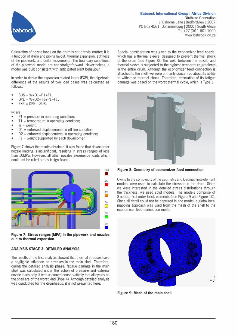
Figure 7 shows the results obtained. It was found that downcomer nozzle loading is insignificant, resulting in stress ranges of less than 10MPa. However, all other nozzles experience loads which could not be ruled out as insignificant.
ANALYSIS STAGE 3: DETAILED ANALYSIS
The results of the first analysis showed that thermal stresses have a negligible influence on stresses in the main shell. Therefore, during the detailed analysis phase, fatigue damage in the main shell was calculated under the action of pressure and external nozzle loads only. It was assumed conservatively that all cycles on the shell are of the worst kind (Type 4). Although detailed analysis was conducted for the drumheads, it is not presented here.
Figure 7: Stress ranges [MPA] in the pipework and nozzles due to thermal expansion.
Special consideration was given to the economizer feed nozzle, which has a thermal sleeve, designed to prevent thermal shock of the drum (see Figure 8). The weld between the nozzle and thermal sleeve is subjected to the highest temperature gradients in the entire drum. Although the economizer feed connection is attached to the shell, we were primarily concerned about its ability to withstand thermal shock. Therefore, estimation of its fatigue damage was based on the worst thermal cycle, which is Type 1.
Figure 8: Geometry of economizer feed connection.
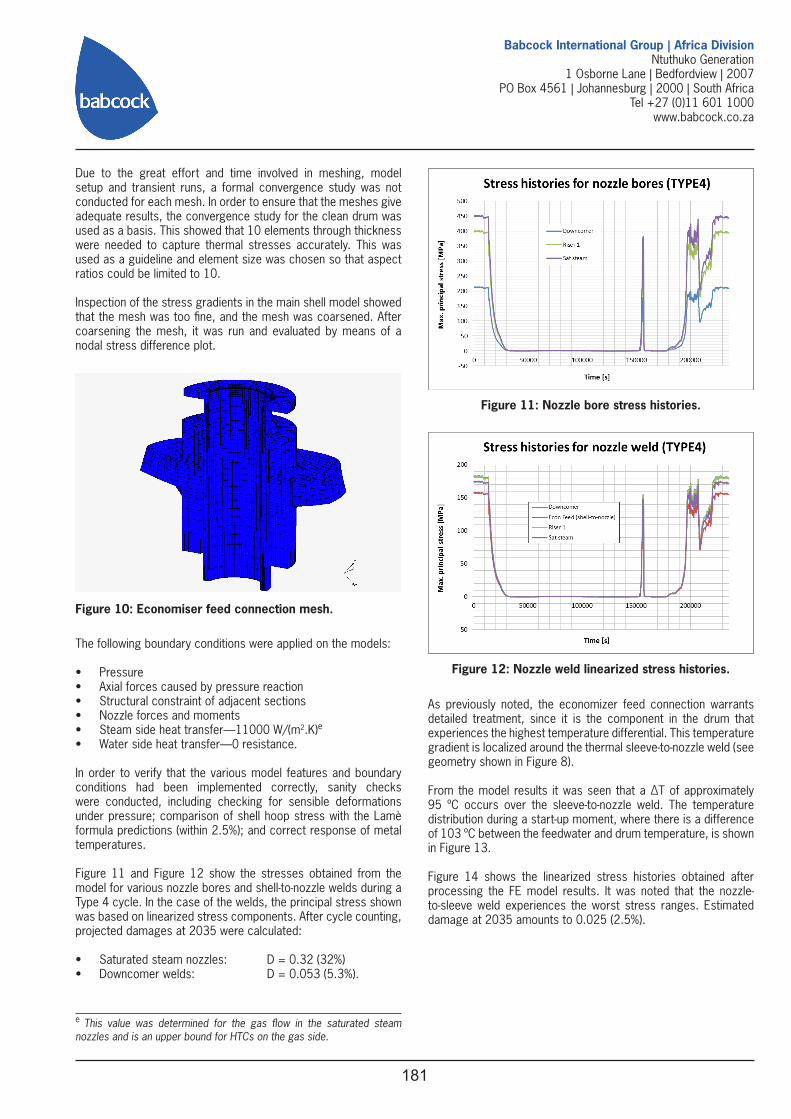
Owing to the complexity of the geometry and loading, finite element models were used to calculate the stresses in the drum. Since we were interested in the detailed stress distributions through the thickness, we used solid models. The models comprise of 8-noded, first-order brick elements (see Figure 9 and Figure 10). Since all detail could not be captured in one model, a global-local mapping approach was used from the mesh of the shell to the economiser feed connection mesh.
Figure 9: Mesh of the main shell.
181
Babcock International Group | Africa DivisionNtuthuko Generation
1 Osborne Lane | Bedfordview | 2007PO Box 4561 | Johannesburg | 2000 | South Africa
Tel +27 (0)11 601 1000www.babcock.co.za
Due to the great effort and time involved in meshing, model setup and transient runs, a formal convergence study was not conducted for each mesh. In order to ensure that the meshes give adequate results, the convergence study for the clean drum was used as a basis. This showed that 10 elements through thickness were needed to capture thermal stresses accurately. This was used as a guideline and element size was chosen so that aspect ratios could be limited to 10.
Inspection of the stress gradients in the main shell model showed that the mesh was too fine, and the mesh was coarsened. After coarsening the mesh, it was run and evaluated by means of a nodal stress difference plot.
Figure 10: Economiser feed connection mesh.
The following boundary conditions were applied on the models:
• Pressure• Axial forces caused by pressure reaction• Structural constraint of adjacent sections• Nozzle forces and moments• Steam side heat transfer—11000 W/(m2.K)e
• Water side heat transfer—0 resistance.
In order to verify that the various model features and boundary conditions had been implemented correctly, sanity checks were conducted, including checking for sensible deformations under pressure; comparison of shell hoop stress with the Lamè formula predictions (within 2.5%); and correct response of metal temperatures.
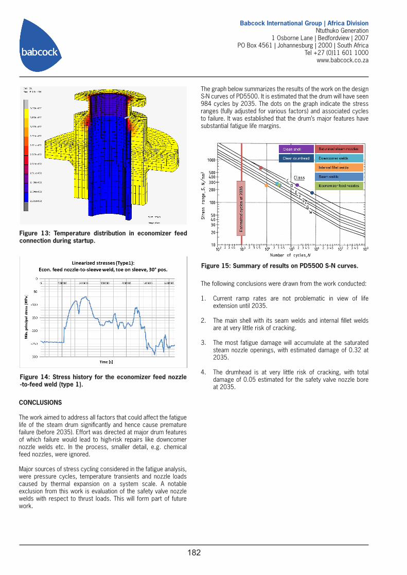
Figure 11 and Figure 12 show the stresses obtained from the model for various nozzle bores and shell-to-nozzle welds during a Type 4 cycle. In the case of the welds, the principal stress shown was based on linearized stress components. After cycle counting, projected damages at 2035 were calculated:
• Saturated steam nozzles: D = 0.32 (32%)• Downcomer welds: D = 0.053 (5.3%).
e This value was determined for the gas flow in the saturated steam nozzles and is an upper bound for HTCs on the gas side.
Figure 11: Nozzle bore stress histories.
Figure 12: Nozzle weld linearized stress histories.
As previously noted, the economizer feed connection warrants detailed treatment, since it is the component in the drum that experiences the highest temperature differential. This temperature gradient is localized around the thermal sleeve-to-nozzle weld (see geometry shown in Figure 8).
From the model results it was seen that a ΔT of approximately 95 ºC occurs over the sleeve-to-nozzle weld. The temperature distribution during a start-up moment, where there is a difference of 103 ºC between the feedwater and drum temperature, is shown in Figure 13.
Figure 14 shows the linearized stress histories obtained after processing the FE model results. It was noted that the nozzle-to-sleeve weld experiences the worst stress ranges. Estimated damage at 2035 amounts to 0.025 (2.5%).
182
Babcock International Group | Africa DivisionNtuthuko Generation
1 Osborne Lane | Bedfordview | 2007PO Box 4561 | Johannesburg | 2000 | South Africa
Tel +27 (0)11 601 1000www.babcock.co.za
Figure 13: Temperature distribution in economizer feed connection during startup.
Figure 14: Stress history for the economizer feed nozzle -to-feed weld (type 1).
CONCLUSIONS
The work aimed to address all factors that could affect the fatigue life of the steam drum significantly and hence cause premature failure (before 2035). Effort was directed at major drum features of which failure would lead to high-risk repairs like downcomer nozzle welds etc. In the process, smaller detail, e.g. chemical feed nozzles, were ignored.
Major sources of stress cycling considered in the fatigue analysis, were pressure cycles, temperature transients and nozzle loads caused by thermal expansion on a system scale. A notable exclusion from this work is evaluation of the safety valve nozzle welds with respect to thrust loads. This will form part of future work.
The graph below summarizes the results of the work on the design S-N curves of PD5500. It is estimated that the drum will have seen 984 cycles by 2035. The dots on the graph indicate the stress ranges (fully adjusted for various factors) and associated cycles to failure. It was established that the drum’s major features have substantial fatigue life margins.
Figure 15: Summary of results on PD5500 S-N curves.
The following conclusions were drawn from the work conducted:
1. Current ramp rates are not problematic in view of life extension until 2035.
2. The main shell with its seam welds and internal fillet welds are at very little risk of cracking.
3. The most fatigue damage will accumulate at the saturated steam nozzle openings, with estimated damage of 0.32 at 2035.
4. The drumhead is at very little risk of cracking, with total damage of 0.05 estimated for the safety valve nozzle bore at 2035.