Embed Size (px)
Citation preview

1
Fatigue Behaviour of Shear Studs to Transfer Dynamic Loads between Steel- and Concrete Construction Elements
Christoph Odenbreit, Université du Luxembourg, Luxembourg-Kirchberg/Luxembourg, [email protected]
Andreas Leffer, Stahl- und Apparatebau Hans Leffer GmbH, Saarbrücken/Germany [email protected]
Markus Feldmann, University of Kaiserslautern, Kaiserslautern/Germany, [email protected]
To proof the fatigue behaviour of shear stud connectors between building elements in steel and concrete, a test method to conduct displacement-controlled push-out tests is presented. The results of the fatigue behaviour for the tested shear studs are shown and a method for fatigue design of shear studs on the basis of the test data is presented.
1 Introduction
For loads, which have to be transferred between building elements in steel and concrete, welded shear studs often form ecological solutions. These shear studs are embedded in concrete and welded onto the steel plate. Figure 1 shows for example sandwich panels from a test series that has been done to explore the structural behaviour of offshore composite ice wall elements in steel and concrete, see Berner (1992).
Figure 1 Composite Offshore Ice Wall, Berner (1992)
Another example is the prefabricated composite sandwich panel forming slender slab elements for offshore use with a very high load bearing capacity. For this application tests and comparing analyses have been done by Liew (2003).
In maritime structures as well as in other applications the shear connectors are often subjected to cyclic loading originated by e.g. wind, waves or heavy traffic in structural steel applications. Therefore special attention has to be paid to the fatigue behaviour of these welding details. In addition

2
the fatigue of the structural steel and the concrete has to be considered. The fatigue failure of the shear stud connection is defined as the failure of the steel detail itself. This can happen in three different modes, as shown in Figure 2.
- Type „A“: The fatigue crack happens in the shear stud, directly at the transition to the weld.
- Type “B”: The fatigue crack happens in the base steel, directly at the transition to the weld.
- Type “C”: The crack starts at the weld, but proceeds into the base metal away from the weld itself.
∆σ ∆σ
Type “B”Type “A” Type “C”
Figure 2 Failure Modes
Over the last two decades a lot of investigations have been carried out to derive a design concept for the proof of the fatigue strength of headed shear studs e.g. Roik, Hanswille (1990), Oehlers (1992) and many others. The concept was finally derived from a statistical reevaluation of more than 280 stress controlled push-out tests, Roik, Hanswille (1990). A fatigue strength curve – the so called Wöhler curve - to determine the lifetime of the shear connector in dependence of the damage equivalent shear stress range was derived, see Figure 3 and Eq. (1):
log N = 22.123 –8 log ∆τR Eq. (1)
This is the classical load-life approach of the nominal stress concept that bases on the assumption of a fully elastic behaviour of the connection in service loads.
Figure 3 Fatigue Strength Curve for Fatigue Stress Range ∆τR, ENV 1994-2 (1999)
Recent investigations e.g. conducted by Kretz (1999), Mensinger (2000) and Leffer (2002) at
3
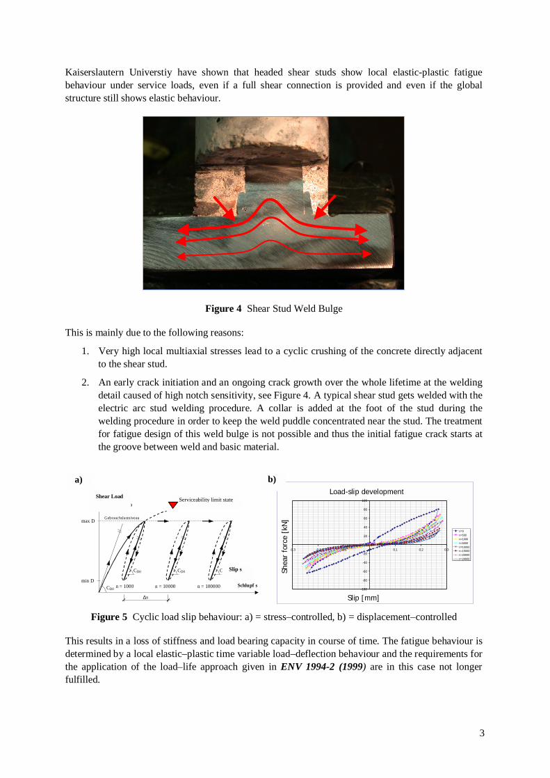
Kaiserslautern Universtiy have shown that headed shear studs show local elastic-plastic fatigue behaviour under service loads, even if a full shear connection is provided and even if the global structure still shows elastic behaviour.
Figure 4 Shear Stud Weld Bulge
This is mainly due to the following reasons:
1. Very high local multiaxial stresses lead to a cyclic crushing of the concrete directly adjacent to the shear stud.
2. An early crack initiation and an ongoing crack growth over the whole lifetime at the welding detail caused of high notch sensitivity, see Figure 4. A typical shear stud gets welded with the electric arc stud welding procedure. A collar is added at the foot of the stud during the welding procedure in order to keep the weld puddle concentrated near the stud. The treatment for fatigue design of this weld bulge is not possible and thus the initial fatigue crack starts at the groove between weld and basic material.
Schlupf s
Dübelkraft D
CD0
n = 1000 n = 100000 CD0
Gebrauchslastniveau max D
min D
CD0
n = 10000
CD0
∆s
Dübelkraft-Schlupf-Hysteresen S9_13
-100
-80
-60
-40
-20
0
20
40
60
80
100
-0.3 -0.2 -0.1 0 0.1 0.2 0.3
Schlupf s [mm]
Düb
elkr
aft P
[kN
]
n=0n=500n=1000n=5000n=10000n=15000n=20000n=24000
Load-slip development
Shear
forc
e [
kN
]
Slip [mm]
Figure 5 Cyclic load slip behaviour: a) = stress–controlled, b) = displacement–controlled
This results in a loss of stiffness and load bearing capacity in course of time. The fatigue behaviour is determined by a local elastic–plastic time variable load–deflection behaviour and the requirements for the application of the load–life approach given in ENV 1994-2 (1999) are in this case not longer fulfilled.
b)
Serviceability limit state
Slip s
Shear Load
a)

4
Therefore a new design concept taking the elastic–plastic fatigue behaviour into account was derived, see Leffer (2002). This concept is – in contradiction to ENV 1994-2 (1999) – derived from
Figure 6 Simplified slip diagram for cyclic loading
displacement controlled push out tests (as well as from large scale beam tests) and uses a modified strain–life approach, using the local displacement slip s instead of the local strain ε at the notch.
2 Internal Mechanisms of the Load Bearing Behaviour of Shear Studs in Fatigue
Headed studs subjected to cyclic loading show a different load–deflection behaviour than headed studs subjected to cyclic displacements, see Figure 5 Cyclic load slip behaviour: a) = stress–controlled, b) = displacement–controlled a) and b).
On the left side, the simplified load–slip behaviour in stress controlled push–out tests, on the right side, a hysteresis development in displacement controlled push–out tests is shown.
Figure 7 Shear Force in the Stud Versus the Rate of Slip Growth – Comparison of Results from Different Authors.
In stress controlled as well as in displacement controlled tests a forceless part in the load–slip hysteresis develops, the plastic range, which is variable in course of time. The fatigue behaviour shown in Figure 5 a) can only be observed if the slip between the structural steel and the concrete can develop without internal or external restrictions, which is normally not given in reality.
Slip [mm]
Range of slip-displacement of the stud with no shear
load
Force [kN]
5
In a composite structure which is internal statically indeterminate only a load–deflection behaviour shown in Figure 5 b) with only some tenth of a millimeter slip growth can occur; see Leffer (2002).
Figure 8 Test Arrangement for Push-Out Tests on Shear Studs
The fatigue behaviour in a real composite structure is rather displacement controlled than stress controlled and depends on the stiffness of the whole shear connection.
The required load–slip development in course of time can better be described in a sufficiently exact manner with the simplified load–slip behaviour, which is shown in Figure 6. To derive a design concept, it is necessary:
- to obtain the stabilized value of the stiffness CDO for the elastic branch of the diagram and
- to find a model to determine the plastic proportion of the total slip at any time.
Many researchers have investigated especially the second point; see Figure 7, Taplin, Grundy (2000). But so far either the statistical correlation was very poor or the basis of the test data was too small or both.
3 Displacement Controlled Push-Out Tests and the Test Results
3.1 Push-Out Tests
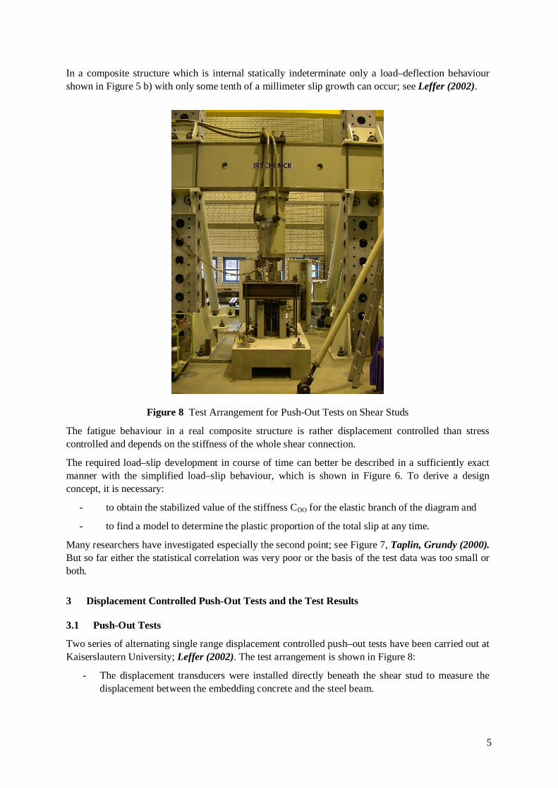
Two series of alternating single range displacement controlled push–out tests have been carried out at Kaiserslautern University; Leffer (2002). The test arrangement is shown in Figure 8:
- The displacement transducers were installed directly beneath the shear stud to measure the displacement between the embedding concrete and the steel beam.
6
- The hydraulic jacks for the cyclic loading were controlled by a computer program via the incoming signal of the displacement transducers.
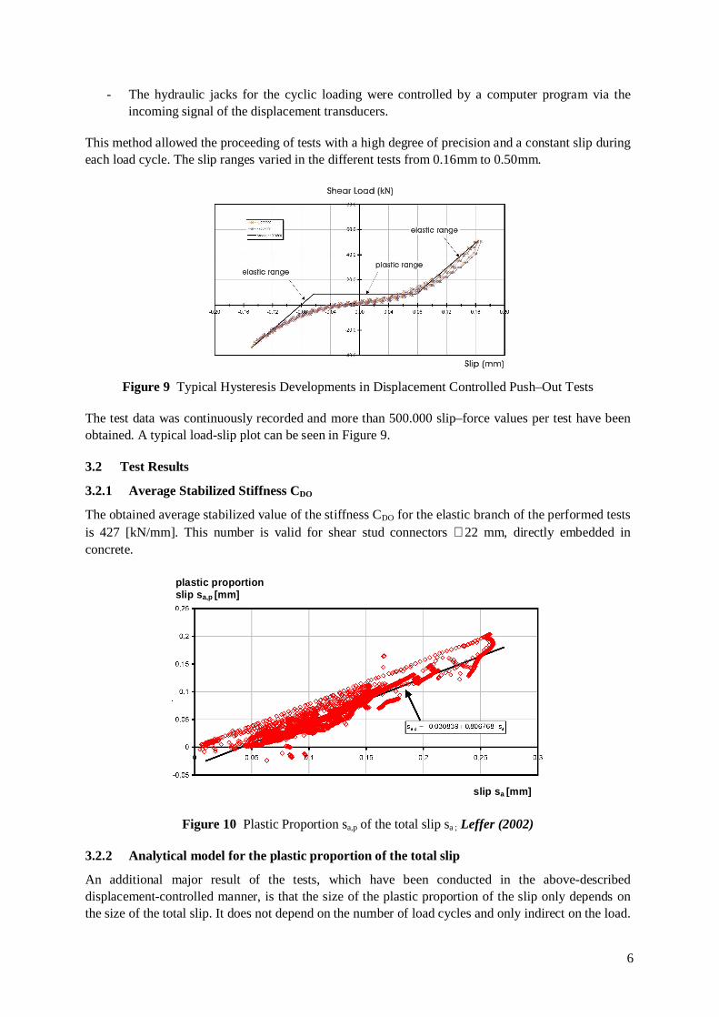
This method allowed the proceeding of tests with a high degree of precision and a constant slip during each load cycle. The slip ranges varied in the different tests from 0.16mm to 0.50mm.
Figure 9 Typical Hysteresis Developments in Displacement Controlled Push–Out Tests
The test data was continuously recorded and more than 500.000 slip–force values per test have been obtained. A typical load-slip plot can be seen in Figure 9.
3.2 Test Results
3.2.1 Average Stabilized Stiffness CDO
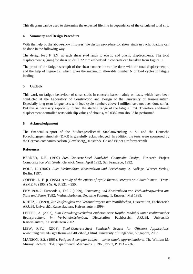
The obtained average stabilized value of the stiffness CDO for the elastic branch of the performed tests is 427 [kN/mm]. This number is valid for shear stud connectors ∅22 mm, directly embedded in concrete.
plastic proportion slip sa,p [mm]
slip sa [mm]
Figure 10 Plastic Proportion sa,p of the total slip sa ; Leffer (2002)
3.2.2 Analytical model for the plastic proportion of the total slip
An additional major result of the tests, which have been conducted in the above-described displacement-controlled manner, is that the size of the plastic proportion of the slip only depends on the size of the total slip. It does not depend on the number of load cycles and only indirect on the load.

7
This is valid for load cycles with a constant- or even with a linear increasing slip size.
The average value of the plastic proportion sa,p of the total slip sa as shown in Figure 10 can be analyzed with Eq. (2):
sa,p = -0.030839 + 0.806768 ⋅ sa,p Eq. (2)
Eq. (2) is valid for values of the total slip above 0.038225 mm. If the slip is smaller, the displacement behaves only elastic.
3.2.3 Stabilized Cyclic Load-Slip Curve and Slip-Wöhler Curve according to Manson, Coffin and Morrow
With the use of the derived average stabilized stiffness CDO in combination with the analytical description of the plastic proportion of the totals slip (Eq. 2), a simplified stabilized load-slip curve can be derived, see Figure 11.
0
5
10
15
20
25
30
35
40
45
50
0 0.1 0.2 0.3 0.4
Shear Force [kN]
Slip [mm]
Figure 11 Stabilized Shear Load – Slip Curve for Shear Studs ∅22 mm Embedded in Concrete
This load-deflection curve can be used to perform nonlinear calculations to obtain the total slip value that is to be expected in course of time within only one nonlinear analyzing step.
Figure 12 Slip-Woehler-Diagram for studs ∅ 22 mm according to Manson, Coffin and Morrow
Further on a modified slip-Woehler diagram according to the strain-life approach, Manson (1965), Coffin (1954) and Morrow (1965), which takes the full elastic-plastic fatigue behaviour into account can be derived; see Figure 12.
8
This diagram can be used to determine the expected lifetime in dependence of the calculated total slip.
4 Summary and Design Procedure
With the help of the above-shown figures, the design procedure for shear studs in cyclic loading can be done in the following way:
The design load F [kN] at each shear stud leads to elastic and plastic displacements. The total displacement sa [mm] for shear studs ∅ 22 mm embedded in concrete can be taken from Figure 11.
The proof of the fatigue strength of the shear connection can be done with the total displacement sa and the help of Figure 12, which gives the maximum allowable number N of load cycles in fatigue loading.
5 Outlook
This work on fatigue behaviour of shear studs in concrete bases mainly on tests, which have been conducted at the Laboratory of Construction and Design of the University of Kaiserslautern. Especially long-term fatigue tests with load cycle numbers above 1 million have not been done so far. But this is necessary especially to find the starting range of the fatigue limit. Therefore additional displacement-controlled tests with slip values of about sa ≈ 0.0382 mm should be performed.
6 Acknowledgement
The financial support of the Studiengesellschaft Stahlanwendung e. V. and the Deutsche Forschungsgemeinschaft (DFG) is gratefully acknowledged. In addition the tests were sponsored by the German companies Nelson (Gevelsberg), Köster &. Co and Peiner Umformtechnik
References
BERNER, D.E. (1992) Steel-Concrete-Steel Sandwich Composite Design, Research Project Composite Ice Wall Study, Gerwick News, April 1992, San Francisco, 1992.
BODE, H. (2002), Euro Verbundbau, Konstruktion und Berechnung, 2. Auflage, Werner Verlag, Berlin, 1997.
COFFIN, L. F. jr. (1954), A study of the effects of cyclic thermal stresses on a ductile metal. Trans. ASME 76 (1954) Nr. 6, S. 931 – 950.
ENV 1994-2: Eurocode 4, Teil 2 (1999), Bemessung und Konstruktion von Verbundtragwerken aus Stahl und Beton, Teil2: Verbundbrücken, Deutsche Fassung, 1. Entwurf, Mai 1999.
KRETZ, J. (1999), Zur Zeitfestigkeit von Verbundträgern mit Profilblechen, Dissertation, Fachbereich ARUBI, Universität Kaiserslautern, Kaiserslautern 1999.
LEFFER, A. (2002), Zum Ermüdungsverhalten einbetonierter Kopfbolzendübel unter realitätsnaher Beanspruchung im Verbundbrückenbau, Dissertation, Fachbereich ARUBI, Universität Kaiserslautern, Kaiserslautern 2002.
LIEW, R.Y.J. (2003), Steel-Concrete-Steel Sandwich System for Offshore Applications, www://eng.nus.edu.sg/EResnews/0406/sf/sf_4.html, University of Singapore, Singapore, 2003.
MANSON, S.S. (1965), Fatigue: A complex subject – some simple approximations, The William M. Murray Lecture, 1964; Experimental Mechanics 5, 1965, No. 7, P. 193 – 226.

9
MENSINGER, M. (2000), Zum Ermüdungsverhalten von Kopfbolzendübeln im Verbundbau, Dissertation, Fachbereich ARUBI, Universität Kaiserslautern, Kaiserslautern 2000.
MORROW, J.D.: (1965), Cyclic plastic strain energy and fatigue of metals. American Society for Testing and Materials, ASTM STP 378, 1965, P. 45-87.
OEHLERS, D.J. (1992), Uni-Directional Fatigue Tests on Stud Shear Connectors, Research Report No.: R87, University of Adelaide, Adelaide 1992.
ROIK, K., HANSWILLE, G. (1990), Hintergrundbericht zu EC4: Nachweis des Grenzzustandes der Betriebsfestigkeit für Kopfbolzendübel, Bericht Ecç/11/90, Bochum, 1990.
TAPLIN, G., GRUNDY, P. (2000), Steel concrete beams under repeated load, Composite Construction Conference IV, Conference Proceedings, Banff, Canada 2000.