Embed Size (px)
Citation preview

Fatigue Design of a Shuttle Tanker for the North Atlantic Operation
October 23rd, 2013
Byung-Ki Choi*, Byoung-Hoon Jung, Young-Ho Seo, Byeong-Rok Lee, Wha-Soo Kim
Hyundai Heavy Industries Co., Ltd.

2/28 Hyundai Maritime Research Institute Shipbuilding Division
Introduction
In general, shuttle tankers are built for the purposes such as
- Frequent loading/unloading
- Specialized for harsh offshore conditions : dynamic positioning(DP) system, redundant propulsion, bow loading systems(BLS)
HHI has designed and built the shuttle tankers for safe and efficient operation with low environmental exposure

3/28 Hyundai Maritime Research Institute Shipbuilding Division
Key Requirements
Winterization in accordance with DNV cold notation
DP 2 positioning over the Goliat extended offloading sector in weather vane and AutoPos modes as applicable to achieve close to 360 degrees operation
Bow loading system (BLS) for cold climate operations
Compatible with the North Sea offloading standard as defined in Statoil’s requirements for shuttle tankers
Optimization on energy consumption and atmospheric releases (NOx and CO2)
Focus on safety and environmental improvements
4/28 Hyundai Maritime Research Institute Shipbuilding Division
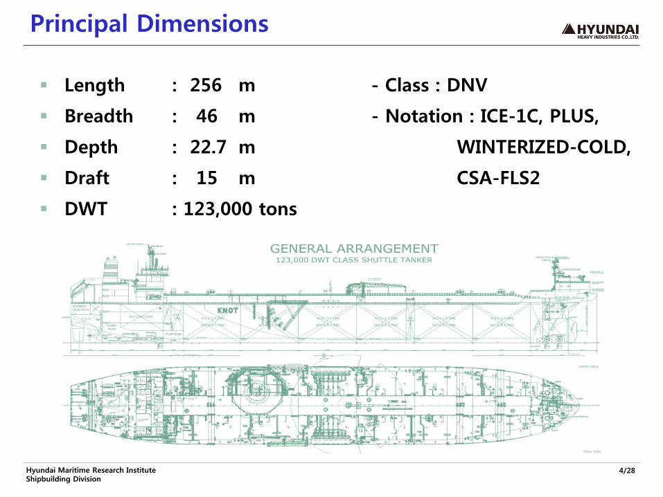
Principal Dimensions
Length : 256 m - Class : DNV
Breadth : 46 m - Notation : ICE-1C, PLUS,
Depth : 22.7 m WINTERIZED-COLD,
Draft : 15 m CSA-FLS2
DWT : 123,000 tons

5/28 Hyundai Maritime Research Institute Shipbuilding Division
Characteristics of Structural Design
Based on design of SUEZMAX class tanker
Design basis for new buildings with requirement of 30 years of fatigue life on the North Atlantic, Norwegian Sea and Barents Sea
DNV notations of PLUS & CSA-FLS2
Deck trunk structure on the main deck
6/28 Hyundai Maritime Research Institute Shipbuilding Division
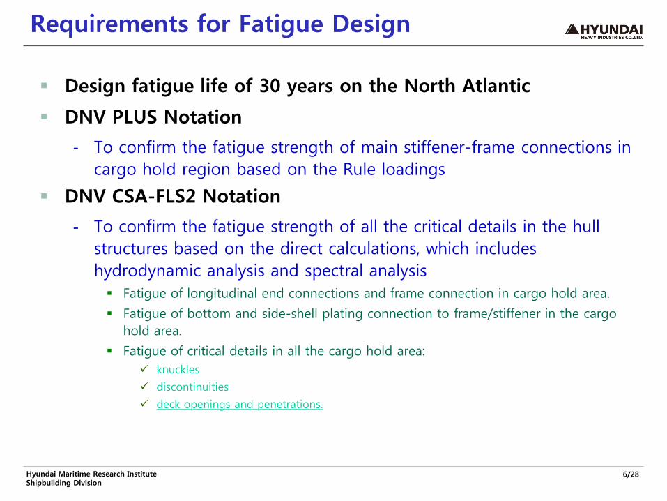
Requirements for Fatigue Design
Design fatigue life of 30 years on the North Atlantic
DNV PLUS Notation
- To confirm the fatigue strength of main stiffener-frame connections in cargo hold region based on the Rule loadings
DNV CSA-FLS2 Notation
- To confirm the fatigue strength of all the critical details in the hull structures based on the direct calculations, which includes hydrodynamic analysis and spectral analysis Fatigue of longitudinal end connections and frame connection in cargo hold area.
Fatigue of bottom and side-shell plating connection to frame/stiffener in the cargo hold area.
Fatigue of critical details in all the cargo hold area: knuckles
discontinuities
deck openings and penetrations.

7/28 Hyundai Maritime Research Institute Shipbuilding Division
PLUS Calculations
General Assumptions
- The vessel is expected to be 42.5% of its lifetime in full load condition and 42.5% in the ballast condition & cargo holds are assumed to be in non-corrosive environment.
The hot spot points & the geometric stress concentration factors KG are applied as specified in CN 34.2.
The maximum principal stress within ±45˚ of the normal to the weld is used for the analysis.
Simplified fatigue analysis is carried out to calculate the fatigue damage for each hot-spot point

8/28 Hyundai Maritime Research Institute Shipbuilding Division
Flowchart for stiffener-frame connections
*Refer to CN 34.2
9/28 Hyundai Maritime Research Institute Shipbuilding Division
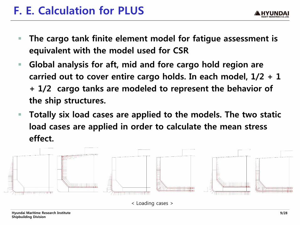
F. E. Calculation for PLUS
The cargo tank finite element model for fatigue assessment is equivalent with the model used for CSR
Global analysis for aft, mid and fore cargo hold region are carried out to cover entire cargo holds. In each model, 1/2 + 1 + 1/2 cargo tanks are modeled to represent the behavior of the ship structures.
Totally six load cases are applied to the models. The two static load cases are applied in order to calculate the mean stress effect.
< Loading cases >
10/28 Hyundai Maritime Research Institute Shipbuilding Division
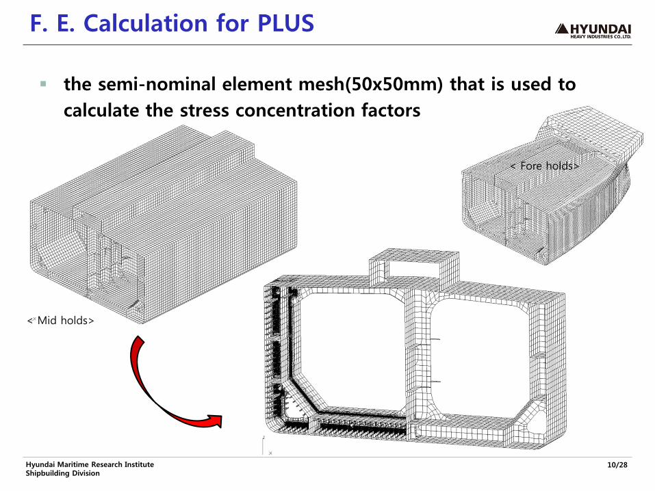
F. E. Calculation for PLUS
the semi-nominal element mesh(50x50mm) that is used to calculate the stress concentration factors
< Mid holds>
< Fore holds>

11/28 Hyundai Maritime Research Institute Shipbuilding Division
Reinforcements from PLUS Notation
Modification to the closed-typed collar plate
Normal scallops to keyhole or soft toe & back brackets
About 1,000 pieces added to enhance the fatigue strength after global screening

12/28 Hyundai Maritime Research Institute Shipbuilding Division
Spectral Fatigue Analysis for CSA-FLS2
All calculations are based on direct calculated wave loads using a 3D hydrodynamic program including effect of forward speed. The pressures and inertia loads from the hydrodynamic analysis are transferred to the FE-models maintaining the phasing definitions.
For CSA-FLS2, two principal fatigue calculation methodologies are used to comply with CSA requirements:
- Full stochastic (spectral) fatigue analysis
- Component stochastic method
It requires a number of numerical calculations related to F. E. calculation and processing of the numeric works
Hard to use the commercial software(SESAM package) due to the limited design schedule

13/28 Hyundai Maritime Research Institute Shipbuilding Division
Procedure of Spectral Fatigue Analysis
Sea State (Hsi, Tzj) (Wave Spectrum, Sw(ω|Hsi, Tzj))
Wave Spreading
Wave Scatter Diagram
Probability Density Function (Rayleigh Distribution)
Short-Term Statistics (m0, m2, m4, fijk , εijk)
Stress Range Response Spectrum (Ss(ω|Hsi, Tzj, θk)
Stress Transfer Function (Stress RAO, Hs(ω|θk))
Partial Damage
Weighting & Summing All Damages
Closed-Form Integration
Total Damage
S-N Curve
Palmgrens-Miner Rule
F. E. Structural Analysis Hot-spot stress, s(ωn,θk)
Ship Motion Analysis for given (ωn,θk)
L/C, Ship Speed(V)

14/28 Hyundai Maritime Research Institute Shipbuilding Division
Development of HDSafe
HFM (Hyundai FEA Manager)
- Handling of loads from ship motion analysis
- Global to local mapping (boundary & loading)
- Automatic job submission (each heading, frequency, phase)
- Manipulation of the FE analysis results
- Hotspot stress extraction
- Generation of the stress transfer function data for HSM
HSM (Hyundai Spectral Manager)
- Database of environmental(wave) data & fatigue data (SN curve)
- Statistical processing (wave spectrum, stress transfer function etc.)
- Component based fatigue analysis and full stochastic fatigue analysis
- Short term and long term fatigue damage prediction
Gap analysis between SESAM & HDSafe was carried out and HDSafe is confirmed to be equivalent & acceptable

15/28 Hyundai Maritime Research Institute Shipbuilding Division
Handling of F. E. Model
Load/boundary interface for global & local model
Definition & extraction of Hot-spot stress

16/28 Hyundai Maritime Research Institute Shipbuilding Division
Damage Calculation
Damage calculation & visualization
Case study based on the databases on wave & S-N data

17/28 Hyundai Maritime Research Institute Shipbuilding Division
Hydrodynamic analysis
Linear wave load analyses are performed for the two loading conditions based on a 2/3 of design speed. The hydrodynamic loads have been calculated using a seakeeping computation program WASIM. FLS design loads for the vessel to be based on:
- North Atlantic wave environment
- Pierson-Moskowitz wave spectrum
- Equal probability of wave heading
- Cos2 wave spreading
- Vessel speed is 2/3 of design speed
Long-term analysis was carried out for assessment of hull girder loading & local pressures based on the 30 years of operation on the North Atlantic
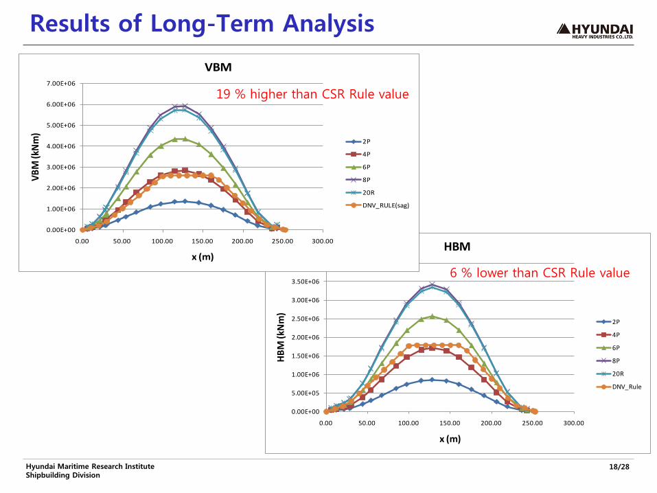
18/28 Hyundai Maritime Research Institute Shipbuilding Division
Results of Long-Term Analysis
0.00E+00
5.00E+05
1.00E+06
1.50E+06
2.00E+06
2.50E+06
3.00E+06
3.50E+06
4.00E+06
0.00 50.00 100.00 150.00 200.00 250.00 300.00
HBM
(kN
m)
x (m)
HBM
2P
4P
6P
8P
20R
DNV_Rule
0.00E+00
1.00E+06
2.00E+06
3.00E+06
4.00E+06
5.00E+06
6.00E+06
7.00E+06
0.00 50.00 100.00 150.00 200.00 250.00 300.00
VBM
(kN
m)
x (m)
VBM
2P
4P
6P
8P
20R
DNV_RULE(sag)
19 % higher than CSR Rule value
6 % lower than CSR Rule value

19/28 Hyundai Maritime Research Institute Shipbuilding Division
External Wave Pressures
0
20
40
60
0 5 10 15 20
CSR
CSA
0
5
10
15
20
25
0 20 40 60 80 100
CSR
CSA

20/28 Hyundai Maritime Research Institute Shipbuilding Division
Results of Component Method
The component stochastic fatigue calculation procedure is based on combination of load transfer functions calculated by the wave load analysis program and stress response factors representing the stress per load ratio.
Hot-spot points to be checked
- (a) all the stiffener end connections at ordinary frames and at transverse bulkheads.
- (b) all the plate welds towards longitudinals(long edge) and frames(short edge)
(a) (b)
21/28 Hyundai Maritime Research Institute Shipbuilding Division
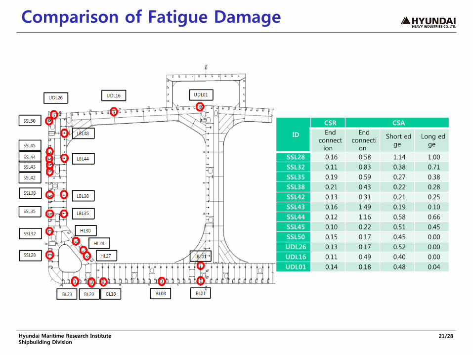
Comparison of Fatigue Damage
ID
CSR CSA End
connection
End connecti
on
Short edge
Long edge
SSL28 0.16 0.58 1.14 1.00 SSL32 0.11 0.83 0.38 0.71 SSL35 0.19 0.59 0.27 0.38 SSL38 0.21 0.43 0.22 0.28 SSL42 0.13 0.31 0.21 0.25 SSL43 0.16 1.49 0.19 0.10 SSL44 0.12 1.16 0.58 0.66 SSL45 0.10 0.22 0.51 0.45 SSL50 0.15 0.17 0.45 0.00 UDL26 0.13 0.17 0.52 0.00 UDL16 0.11 0.49 0.40 0.00 UDL01 0.14 0.18 0.48 0.04

22/28 Hyundai Maritime Research Institute Shipbuilding Division
Full Stochastic Analysis
To be performed using a global structural model and local fine-mesh sub-models.
It is required that the wave loads are transferred directly from the hydrodynamic analysis to the structural model. The load transfer ensures that the loads are applied consistently, maintaining load-equilibrium.
From local stress concentration models the geometric stress transfer functions at the hot spots are determined by the t x t elements that pick up the stress increase towards the hotspot.
The global screening analysis is carried out to calculate allowable stress concentrations in the trunk deck & the upper deck and also to find the most fatigue critical detail from a number of similar or equal details.

23/28 Hyundai Maritime Research Institute Shipbuilding Division
Free Surface Effect on Hydrodynamic Load
How to take into account the free surface effect in the cargo or ballast tank correctly in carrying out the hydrodynamic analysis and load generation on the global model
- Modification of GM by re-distribution of the weight or modifying the stiffness matrix(C44) directly in the potential code
- This modification causes an unfavorable hull girder loading such as the torsional moment and horizontal bending moment.
0.00E+00
1.00E+04
2.00E+04
3.00E+04
4.00E+04
5.00E+04
6.00E+04
0 0.2 0.4 0.6 0.8 1 1.2
RAO of Torsional Moment
with Additional C44
without Additional C44

24/28 Hyundai Maritime Research Institute Shipbuilding Division
Treatment of the Unbalancing Forces
Deviation of still water loading caused by how to consider the limited data of weight
- Loading manual vs. hydrodynamic model
Large forces and moments at the reaction points are normally caused by errors in the load transfer but inevitable in some cases, i.e. for taking into account the free surface effect and effect of intermittent wet surfaces in waterline region.
- No clear guidance on usage of inertia relief method to remove the unbalancing forces generated during load transfer of hydrodynamic loading to F. E. model
25/28 Hyundai Maritime Research Institute Shipbuilding Division
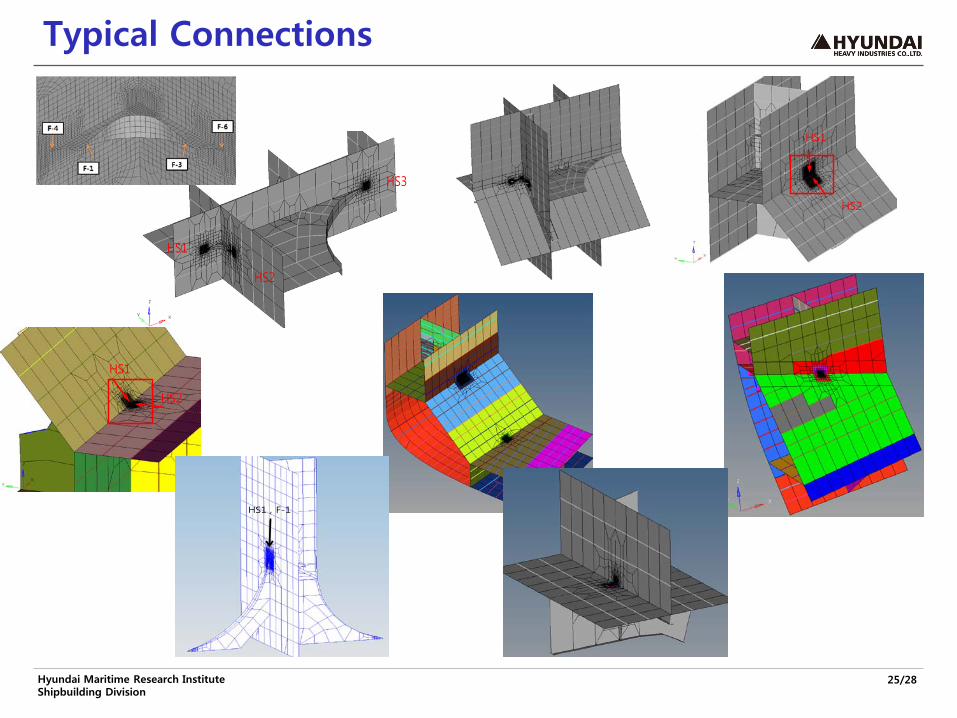
Typical Connections
HS1
HS2
HS3
HS1
HS2
HS1
HS2
HS1 , F-1

26/28 Hyundai Maritime Research Institute Shipbuilding Division
Special Details

27/28 Hyundai Maritime Research Institute Shipbuilding Division
Results of Global Screening

28/28 Hyundai Maritime Research Institute Shipbuilding Division
Conclusions
HHI has carried out fatigue design for the shuttle tanker which should be operated in the harsh environment using HHI’s own analysis system and all the critical details satisfied the requirement of fatigue strength.
It is necessary that the clearer guidance for carrying out the spectral fatigue analysis in order to complete a huge amount of the calculations without any human errors within the limited schedule of design & construction of the special-purposed vessels.
It is recommended that the some cooperative studies would be proposed to investigate the uncertainty of the direct calculation and to develop the unified methods for the spectral method.