Embed Size (px)
Citation preview

FATIGUE EVALUATION ON JOINTS AND FRAME OF A BICYCLE MANUFACTURED IN BAMBOO
(EVALUACIÓN DE LA FATIGA EN UNIONES Y MARCO DE BICICLETA FABRICADA EN BAMBÚ)
JUAN PABLO ARANGO FIERRO JOSE LUIS ARANGO FIERRO
UNIVERSIDAD AUTÓNOMA DE OCCIDENTE
FACULTAD DE INGENIERÍA DEPARTAMENTO DE ENERGÉTICA Y MECÁNICA
PROGRAMA DE INGENIERÍA MECÁNICA SANTIAGO DE CALI
2017

FATIGUE EVALUATION ON JOINTS AND FRAME OF A BICYCLE MANUFACTURED IN BAMBOO
(EVALUACIÓN DE LA FATIGA EN UNIONES Y MARCO DE BICICLETA FABRICADA EN BAMBÚ)
JUAN PABLO ARANGO FIERRO 2126543
JOSE LUIS ARANGO FIERRO 2120329
PROYECTO DE GRADO PARA OPTAR AL TÍTULO DE INGENIERO MECÁNICO
Director HECTOR ENRIQUE JARAMILLO
Ingeniero Mecánico, PhD
UNIVERSIDAD AUTÓNOMA DE OCCIDENTE FACULTAD DE INGENIERÍA
DEPARTAMENTO DE ENERGÉTICA Y MECÁNICA PROGRAMA DE INGENIERÍA MECÁNICA
SANTIAGO DE CALI 2017

3
NOTA DE ACEPTACIÓN:
Aprobado por el Comité de Grado en cumplimiento de los requisitos exigidos por la Universidad Autónoma de Occidente para optar al título de INGENIERO MECÁNICO
EMERSON ESCOBAR
Jurado
MAURICIO BARRERA
Jurado
Santiago de Cali, 22 de septiembre de 2017

4
ACKNOWLEDGMENTS (SPANISH VERSION)
Agradecemos de manera especial primeramente a Dios por permitirnos llegar a este punto tan importante de la vida para cualquier profesional y llenarnos de capacidad para terminar nuestra carrera y este trabajo de grado lleno de retos.
Agradecemos a nuestra familia, especialmente a nuestros padres y abuelos quienes con su aporte no solamente económico sino con su amor nos inspiraron a seguir adelante.
Agradecemos a nuestros amigos, la manada y colegas por todas aquellas vivencias que tuvimos a lo largo de nuestra carrera universitaria y por haber hecho de dicha experiencia algo increíble.
Agradecemos a María Paula y Gabriela por darnos su amor, apoyo y comprensión que nos permitieron llevar a cabo este proyecto tan importante para nuestras vidas que son solo el comienzo de un sinfín de sueños al lado de ustedes.
Agradecemos a nuestros profesores quienes nos impartieron sus conocimientos y sabiduría los cuales usamos para alcanzar nuestra profesión.
Agradecemos a nuestro director Héctor Jaramillo quien nos guió a través de este sendero, ofreciendo su vasta experiencia en el campo de la investigación.
Agradecemos a Jaime Buitrago quien con su experiencia y conocimiento en el campo que decidimos estudiar, realizó numerosos aportes a nuestro trabajo de grado.
Agradecemos a Sonia Quintero y el equipo de BambooCo Bikes por habernos confiado tan hermoso proyecto con una visión admirable. Por ustedes realizamos nuestro trabajo de grado.
Agradecemos a la dirección de investigaciones de la Universidad Autónoma de Occidente quienes nos proporcionaron su apoyo económico y técnico a través de los laboratorios de la universidad.
Agradecemos a la Universidad del Valle por su apoyo técnico durante el proceso de tesis.

5
CONTENT
pág.
ABSTRACT 10
INTRODUCTION 11
1. PROJECT DETAILS 14
1.1 DESCRIPTION OF THE PROBLEM 14
1.2 THEORETICAL FRAMEWORK 15
1.2.1 Bamboo 15
1.2.2 Three point bending test 15
1.2.3 Fatigue 18
1.2.4 Finite Element Method 20
1.2.5 FEA Beam analysis 22
2. OBJECTIVES 23
2.1 GENERAL 23
2.2 SPECIFIC 23
3. METHODOLOGY 24
4. FRAME ANALYSIS 26
5. EXPERIMENTAL PROCEDURES 27
5.1 GEOMETRY 27
5.2. MECHANICAL PROPERTIES OF BAMBOO. 27
5.1.2 Finite Element Analysis of the bicycle frame 28
5.1.3 Finite element model calibration 30
5.2 DYNAMIC TEST 31

6
5.2.1 Dynamic analysis 31
5.3 MODAL ANALYSIS 33
5.4 FATIGUE ASSESSMENT 35
6. RESULTS 38
6.1 ELASTICITY MODULUS 38
6.2 EXPERIMENTAL JOINT DISPLACEMENTS 39
6.3 FINITE ELEMENT ANALYSIS AND MODEL OPTIMIZATION 39
6.4 FRAME DYNAMIC RESPONSE VIA FEA 40
6.5 MODAL SIMULATION 43
6.6 FATIGUE ASSESSMENT RESULTS 44
7. DISCUSION AND CONCLUSIONS 45
7.1 MODULUS 45
8. FUTURE WORK 48
8.1 EXPERIMENTAL FATIGUE METHODOLOGY OF THE BIKE FRAME 48
REFERENCES 53

7
TABLES LIST
pag.
Table 1. Dimensions of the bike frame components 29
Table 2. Young’s modulus for thicker bamboo 38
Table 3. Young’s modulus for thinner bamboo 39
Table 4. Vertical and horizontal displacements of points A, B, and C 39
Table 5. Young modulus at frame joints obtained from the simulation. 40
Table 6. Maximum stress and displacements at control points 42

8
FIGURES LIST
pag.
Figure 1. Three point bending test 16
Figure 2. Load vs displacement representative graphic 17
Figure 3. Bamboo tube cross section 18
Figure 4. S-N Diagram 19
Figure 5. Fatigue test with a vertical load. 20
Figure 7. Methodology flow diagram 25
Figure 8. Bicycle made of bamboo 26
Figure 9. Dimensions in mm of the bicycle. 27
Figure 10. Setup three point bending test 28
Figure 11. Bicycle frame FEA model. 29
Figure 12. Experiment setup of bike at the universal testing machine 30
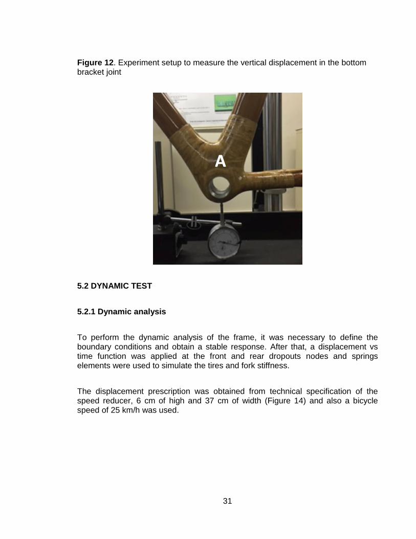
Figure 13. Experiment setup to measure the vertical displacement in the bottom bracket joint 31
Figure 14. Road profile (Measurements in mm.) 32
Figure 15. Bike model 33
Figure 16. Results of the first mode in FE modal analysis (Part 1) and results from the test (Part 2) 34
Figure 17. Modal Experimental Test. 35
Figure 18. Stress vs fatigue life of bamboo. 37
Figure 19. Typical Force vs Displacement behavior of a bamboo specimen under three-point bending stress. 38
Figure 20. FE bicycle frame model displacement 40
Figure 21. Dynamical simulation on FEA 41

9
Figure 22. Reaction forces in magnitude at dropouts joint zone 42
Figure 23. First mode in modal analysis (FEA) (Part 1) and experimental results (Part 2) 43
Figure 24. Stress vs time graphic in dynamical response of the frame submitted to cyclic loads 44
Figure 25. Microscopical section view for thinner bamboo specimen (1X) 46
Figure 26. Microscopical section view for thicker bamboo specimen (1X) 46
Figure 27. Vascular bundle scheme in a section view of a bamboo specimen. 47
Figure 28. Generic specimen representative of the rear dropout joint 47
Figure 29. Song's S-N Curve with deviation curves. 49
Figure 30. Fatigue machine Instron 8872 with a bamboo bike frame. 51
Figure 31. Bike with its support fixture 52

10
ABSTRACT
An engineering proposal has been initiated to (1) evaluate numerically and experimentally the structural behavior of bicycle frames made of bamboo, both under static and dynamic loads, and (2) ensure and control the quality control of the manufacturing process of the frames. The program has been developed with the support of two engineering faculty at Universidad Autonoma de Occidente.
Key words:
Bicycle, Frame, Bamboo, Fatigue, Test.

11
INTRODUCTION
Bicycles offer an alternative cost-effective transportation primarily for low income communities1. Additionally, bicycles offer other advantages, such as zero greenhouse gas emissions, low cost maintenance, quick displacement in high density traffic zones and promotes physical fitness for the users2.
Conventional bike frames, using materials such as steel3, aluminum4,5, carbon fiber6,7 and titanium8, have been studied via numerical modelling and tests of actual frames. Numerical studies generally use the finite element method, whereas experimental tests focus on static load carrying capacity in order to improve the strength/weight ratio. However, new topics of research focus on replacing traditional frame materials by alternative,9 low-cost and environmentally friendly
1 SUE-YEN TJONG, Tjin Tai, et al. How the Netherlands became a bicycle nation: Users, firms and
intermediaries, 1860 – 1940. In: Business History. April, 2015, vol. 57, no. 1, p. 262.
2 BOGOTA. Cinco razones por las que aumenta el uso de la bicicleta [on line]. In: El Tiempo.
Bogotá, 17 of November 2014. 1. [Consulted: 27 of April of 2017]. Available at: http://www.eltiempo.com/archivo/documento/CMS-14840669.
3 . PETERSON, Leisha A. et al. Finite-Element Structural Analysis: A New Tool for Bicycle Frame
Design The Strain Energy Design Method. In: Bicycling Magazine’s Newsletter for the Technical Enthusiast. Summer 1986. vol. 5. No.2. p. 1.
4 PETERSON, Leisha A. et al. Finite-Element Structural Analysis: A New Tool for Bicycle Frame
Design The Strain Energy Design Method. In: Bicycling Magazine’s Newsletter for the Technical Enthusiast. Summer 1986. vol. 5. No.2. p. 1.
5 CICERO, S. et al. Analysis of the cracking causes in an aluminum alloy bike frame. In:
Engineering Failure Analysis. January, 2011, vol 18. No. 1, p. 39.
6 LIUA, Thomas Jin-Chee et al. Fiber direction and stacking sequence design for bicycle frame
made of carbon/epoxy composite laminate. In: Materials and Design. April, 2010, vol. 31, No. 4. p. 1975.
7 LESSARD, Larry B et al. Utilization of FEA in the design of composite bicycle frames. In:
Composites. December, 1995, vol. 26. No. 1. P.72
8 FORD, J. Mountain bike has the missing links. In: Engineer. Decemeber, 2016. No. 5, p. 297
9 RAZALI, N, et al. A study on chemical composition, physical, tensile, morphological, and thermal
properties of roselle fibre: Effect of fibre maturity. In: BioResources. June, 2015, vol. 10, No. 1, p. 1819.

12
materials in order to construct novel frames that are also very attractive aesthetically10.
Bamboo is one of the most attractive environmentally friendly materials. There are more than 1000 species of bamboo around the world of which 70 are abundant in South America and Asia11. Bamboo is a natural fiber specie that belongs to grass Poaceae family and subfamily Bambusoideae, and grows in diverse types of climate. Compared to trees, the bamboo is characterized by a low density, high strength and stiffness12. Also, bamboo plays an important environmental role by preventing ground erosion and landslides in mountainous zones, and retaining significant amounts of water that restores ground conditions where it grows13.
A project named BambooCo Bikes14 is now in progress in Cali, Colombia, under the leadership of the Ecocultura Foundation15 in collaboration with the Escuela para la vida Foundation16, Coladisos17, Craig Calfee18 and Bochika19. Under this
10
. ALVES FIDELIS, M. et al. The effect of fiber morphology on the tensile strength of natural fibers. In: Journal of Materials Research and Technology. April – June, 2013, vol 2, No, 2, p. 152.
11 ZAKIKHANI, P. et al. Extraction and preparation of bamboo fibre-reinforced composites. In:
Materials and Design. November, 2014, vol.63, p. 827.
12 OSORIO, L. et al. Morphological aspects and mechanical properties of single bamboo fibres and
flexural characterization of bamboo/epoxy composites. In: Journal of Reinforced Plastics and Composites. March, 2011. vol. 5, p. 400.
13 ZHOU Ben-zhi, et al. Ecological functions of bamboo forest: Research and Application. In:
Journal of Forestry Research. December 2005. No. 2, p. 145.
14 BAMBOOCO BIKES PROJECT. Bambooco bikes project [Online]. Ecocultura. Cali. (March 5,
2015) [Consulted 28th April 2017]. Available at: https://ecoculturablog.wordpress.com/about-bambooco-bikes/.
15 ECOCULTURA, Ecocultura. Sustentabilidad, comunidad y creatividad [Online].Ecocultura. Cali.
(Since 19 September 2011) [Consulted: 28th April 2017]. Available at: https://ecoculturablog.wordpress.com/.
16 ESCUELA PARA LA VIDA. Construyamos juntos un mundo más feliz [Online] Fundación escuela
para la vida. Cali. (Since September 23 2013), parr. 3 [Consulted: 28th April 2017]. Available at: http://www.escuelaparalavida.org/.
17 Corporación Laboratorio de Diseño Sostenible [Online]. Coladisos. [Consulted: 28
th April 2017].
Available at: https://coladisos.jimdo.com/.
18 About us [Online]. CALFEE DESIGN [Consulted: 28
th April 2017]. Available at:
http://calfeedesign.com/.
19 Our Work [Online]. Bochika [Consulted: 28
th April 2017]. Available at: http://www.bochika.org/.

13
project, bike frames are being manufactured by low-income youths using colombian bamboo joined with a novel composite designed using epoxy and a natural fiber (fique) following a specific process. This thesis will be the basis to demonstrate the structural integrity, both under static and dynamic conditions, of the frames with the objective of exporting them to Europe and US.
Few information can be found in the literature about the strength of bamboo frame bikes, although some analyses have been made using the finite element method20. However, no information regarding the fatigue performance of bamboo bikes frames could be found. Once experimental data has been gathered, sensitive studies regarding fatigue performance and thus useful life of the bamboo bikes can be assessed. This is the main focus of the current study.
20
KINGSLEY Ukoba, et al. Finite Element Analysis of Bamboo Bicycle Frame. In: British Journal of Mathematics & Computer Science. November, 2014, vol. 5, no. 5 p. 585. p. 583 – 594.

14
1. PROJECT DETAILS
1.1 DESCRIPTION OF THE PROBLEM
Historically, bike frames have been constructed of metallic tubes made of steel, aluminum, or titanium alloys and, the joints used welding. Most modern frames are fabricated from carbon fiber reinforced composites where carbon fibers are impregnated using polymeric resins and woven until the entire frame geometry is obtained. The composite frames are very strong and the joints provide a smooth transition between the tubes, improving the structural performance of the frame.
However, bikes made using conventional materials produce an environmental impact. This is one of the reasons why, BambooCo bikes, MTB and Cross, use a renewable bamboo for the frame and the joints are made of a composite resin and natural Fique fibers.
The Ecocultura Foundation does not have studies related to the quality control of the manufacturing process and performance of the bike. Then, the foundation only sells bikes to the local market. In this direction, the foundation needs to perform further studies in order to determine the mechanical behavior of the bike if they want to access the global market.
Several institutions, shops and even countries, in Europe, such as Netherlands21, are interested in buying and commercialize bamboo bike frames, but they requested technical data on the structural behavior of bamboo frames in order to guarantee the quality of the bike-frames.
Then, the research question is:
What is the fatigue structural behavior of a bamboo bicycle frame and its joints?
21
SUE-YEN TJONG, Tjin Tai, et al. How the Netherlands became a bicycle nation: Users, firms and intermediaries, 1860 – 1940. In: Business History. April, 2015, vol. 57, no. 1, p. 257 – 289.

15
1.2 THEORETICAL FRAMEWORK
1.2.1 Bamboo
Bamboo is a grass belonging to the Bambusoideae22, a subfamily that is thought to be an early offshoot in the grass family lineage. Hill et al. [22] It is estimated that there are approximately 45 types and 480 species of bamboo, some of them having a growing rate of one meter per day [22]. The upper nodes of fully elongated culms give rise to small, horizontal branches. Some bamboos flower every year, many bloom only at the end of their lifetimes, which may range from 10 to 120 years.
Bamboos can be found mainly in tropical and subtropical regions, with large concentrations in Asia and South America. A few species reach mild temperate areas. In the United States, there is a single native species, Arundinaria gigantea, called cane. It forms canebrakes in southern bottomlands. Bamboos are also grown as ornamentals plants in many parts of the world. Dense bamboo thickets are sometimes planted as living fences or barricades. In Asia, bamboos are very significant economically, providing materials for building, matting, and many other purposes. The young shoots are popular as food in eastern Asia.
1.2.2 Three point bending test
One test used to characterize the structural behavior of materials is the three point bending test, as illustrated in Fig.1. In this test, the load is applied perpendicularly at midspan of a simply supported beam23 and can be used to obtain the Young’s modulus of the beam material, knowing the applied force (P), the distance between
22
HILL, J F. Grasses and bamboos [Online]. In: Salem Press Encyclopedia Of Science. January 2017 [Consulted: June 5
th, 2017]. September, 2014, vol. 5, no, 1, p. 3 Available at:
ezproxy.uao.edu.co:2048/login?url=http://search.ebscohost.com/login.aspx?direct=true&db=ers&AN=89551719&lang=es&site=eds-live.
23 HANSDAH. Krishna. Three Point Bending Test (Flexural Test). [Online]. 3 point bend test.
Kharagpur, India. 07th November 2017, p. 16. [Consulted: 5th june 2017]. Available at: https://es.slideshare.net/kkh007/3-point-bend-test

16
supports (L)24 , and the deflection at midspan, via the formulation for the elastic solution for the displacement at midspan.
Figure 1. Three point bending test
Source: KOPELIOVICH, D. 3-point Flexure Test [image]. Flexural strength tests of ceramics. Be’er Sheva: Substech. 2012. p. 01. [Consulted: 5th June 2017]. Available online at: http://www.substech.com/dokuwiki/doku.php?id=flexural_strength_tests_of_ceramics.
The test measures the force required to bend the beam and the displacement of the mid-point where the load is applied25. The test can be performed using a universal testing machine to obtain a load vs displacement curve (Figure 2).
24
THE THREE POINT BENDING TEST. [Online]. Machine Intelligence Laboratory. Cambridge University Department of Engineering [Consulted: June 5
th 2017]. Available at:
http://mi.eng.cam.ac.uk/IALego/bender_files/bend_theory.pdf
25 Flexure Test. [Online]. Instron [Consulted: 5
th June 2017]. Available at: http://www.instron.us/en-
us/our-company/library/test-types/flexure-test

17
Figure 2. Load vs displacement representative graphic
Source: SOURADEEP, G. Analysis and Design Of 2-D Tubular Frame Using USFOS Modeling [Image]. Civil Engineering Portal. Kent Ridge, Singapur: Civil Engineering Portal. 2010 [Consulted: 5th June 2017]. Available online at: http://www.engineeringcivil.com/analysis-and-design-of-2-d-tubular-frame-using-usfos-modeling.html.
For a simply supported beam, the Y displacement of the specimen is given by:
𝑌 =𝑃𝐿3
48𝐸𝐼 (1)
If the applied load P and the displacement Y are known, then the Young’s modulus E can be obtained as:
𝐸 =𝑃𝐿3
48𝑌𝐼 (2)
Where, L is the distance between supports and I the moment of inertia of the cross section.
The moment of inertia was calculated using Equation (3), where Dext is the outer diameter and Dint is the inner diameter (Figure 3):

18
𝐼 =𝜋
64(𝐷𝑒𝑥𝑡
4 − 𝐷𝑖𝑛𝑡4) (3)
Figure 3. Bamboo tube cross section
1.2.3 Fatigue
When structural components are subjected to external loads fluctuating in time, the internal stresses induced in the component can cause fatigue26 failure. If alternating stress or completely reversed stress has considerable magnitude a failure on any of the components can be induced, and in some case, the failure can occur when the maximum load is applied many times, but the stress may be lower than the static strength.
During the fatigue process, the component suffers a gradual degradation due to the development of cracks that eventually propagate to sizes that lead to fracture at load levels even below the elastic limit.
Static loads superimposed on the fluctuating loads accelerate the fatigue damage of the material, in particular, when the static load is tensile in nature. In the case a bicycle moving on a road, the dynamic response of the frame due to the irregularities of the road surface induce the time variable loads whereas the weight of the rider would be a static load.
26
JARAMILLO, Héctor Enrique. Fatiga. In: Resistencia de materiales. Algunos temas especiales. 1st ed. Colombia, Cali: Editorial Universidad Autónoma de Occidente. 2013. p. 514.

19
The fatigue strength of materials is generally represented using a strength versus number of cycles diagram, called the S-N curve.
The S-N curve defines the alternating stress (Sa) versus the cycles numbers (N) required to cause the failure (Figure 4).
Figure 4. S-N Diagram
Source: AUTODESK. Stress life technique [image]. Theoretical Overview. San Rafael: Autodesk Help. 2016. [Consulted: 17th may 2017]. Available online at: https://knowledge.autodesk.com/support/simulation-mechanical/learn-explore/caas/CloudHelp/cloudhelp/2017/ENU/SimMech-FatigueWizard/files/GUID-67ACAD8D-105B-444A-B559-0499B5E3673D-htm.html
Among several standards dealing with the structural behavior of bicycles, the ASTM F2711-0827, F2043-1328 and EN 1476629 can be mentioned.
27
ASTM F2711-08(2012), Standard Test Methods for Bicycle Frames. West Conshohocken, Pennsylvania. ASTM International. September, 2012. no. 1. p. 60.
28 ASTM F2043-13, Standard Classification for Bicycle Usage. West Conshohocken, Pennsylvania.
ASTM International. September, 2013, no 1. p. 63.
29 UNE-EN 14766:2005. Fatigue test with a vertical load. Mountain-bicycles - Safety requirements
and test methods. London. European Committee for Standardization. November, 2005. no. 01. p. 52.

20
The standards to evaluate the fatigue performance of bicycle frames require a test setup where the frame is positioned at its normal attitude with the rear dropouts set free to rotate but without displacement (Figure 5), while the front axle is free to move and rotate. In this way, the whole frame is free to bend as it is case when used in a road.
A bar is used to simulate the seat-stem and it is inserted at 70 mm of distance from the top of the seat tube. The load at the bar simulates the weight of the rider. (Fig. 5). Then 50.000 test cycles load between 0 to 1.200 N are applied vertically downward using a 25 Hz of frequency. From a practical standpoint, this cyclic load regime seems arbitrary and not related to any particular road the bicycle would be travelling.
Figure 5. Fatigue test with a vertical load.
Source: UNE-EN 14766:2005. Fatigue test with a vertical load. Mountain-bicycles - Safety requirements and test methods [Image]. London. European Committee for Standardization. November 2005. no. 01. p. 52.
1.2.4 Finite Element Method
To verify the design safety, engineers use many tools and techniques in order to prove that the product work optimally under a wide range of conditions. The finite element method is a technique to achieve this purpose.

21
The first development can be traced back to the work of A. Hrennikoff30, 1941 and R. Courant31, 1943, but these two pioneers used different perspective in their finite element approaches, and pointed out one common essential characteristic: Mesh discretization of a continuous domain into a set of discrete sub-domains.
Another fundamental mathematical contribution to the finite element method is shown in the book “An analysis of finite element method32”·. Clough published the first paper on the finite element method33”, term coined in the 1960. General motors and IBM build computer system DAC-1 (Design Augmented by computers) to facilitate car design in 1959. William Fetter from Boeing in 1960 coined the term “Computer graphics” for his human factors cockpit drawings. In 1965 Nastran (NASA structural analysis) is developed as structural analysis solver tool. In 1977 FIESTA, developed the first professional FEM p-version code. At 1987 MECHANICA, developed by RASNA Corp. P-version FEM in 2001 proved to be the most efficient for plasticity analysis by A. Duster34.
The finite element method is one of the most powerful numerical techniques used to solve differential equations of initial and boundary value problems in geometrically complicated regions. Many of the problems that involve physics laws for space-time are usually expressed in terms of partial differential equations. Most of the geometries and problems that arise everyday pose partial differential equations that cannot be solved using analytical methods, but approximations can be constructed based in different types of discretization. These discretization methods approximate the partial differential equations with numerical model equations which can be solved using numerical methods. The solutions of these numerical model equations are an approximation of the real solution to the partial differential equations because they take the error estimation, in order to converge to the solution and compute such approximations. The FEA is the most popular
30
HRENNIKOFF, A. Solution of problems of elasticity by the framework method. Journal of applied mechanics. 1941. Vol. 8. p. 172.
31 COURANT, R. Variational methods for the solution of problems of equilibrium and vibrations.
New York, USA: Bulletin of the American Mathematical Society. 1943. Vol. 49. p. 20.
32 STRANG, G.& FIX, G. An Analysis of the Finite Element Method. Oxford, UK: Prentice Hall.
1973. 400 p.
33 CLOUGH, R.W. The Finite Element Method, in Plane Stress Analysis”, Proc. 2nd A.S.C.E. Conf:
on Electronic Comp., Pittsburgh, PA. 1960
34 DUSTER, A. The p-version of the Finite Element Method compared to an adaptive h-version for
the deformation theory of plasticity. In: Computer Methods in Applied Mechanics and Engineering Journal Impact Factor & Information. January, 2001, Vol. 190, no. 15, p. 1928. ISSN 0045-7825. 1925 - 1935

22
technique to solve complex engineering problems because the process is very methodical and relatively easy to apply. The FEA discretizes the problem into a set of logical steps that can be implemented on a computer.
Once the experimental data is calibrated, the use of the finite element method saves money and time as it can provide stress and strain fields numerically in a computer and enormously facilitates sensivity studies under different boundary conditions, loads, and material, decreasing the number of experimental tests to evaluate the structural behavior of the frames.
The use of the finite element method offers a great freedom in the selection of discretization. The theory is well developed, due to the close relationship between the numerical formulation and the weak formulation of the partial differential equation problem. The theory provides useful error estimation when the numerical model equations are solved on a computer.
Another benefit of the finite element analysis is that it represents a valuable tool to simulate potentially dangerous, destructive or impractical loading conditions and failure modes. Several failure modes or physical events can be tested within a common model. Elements or structures can be analyzed by different types of analysis35.
1.2.5 FEA Beam analysis36
The beam element is based on the Euler-Bernoulli beam theory that is applicable for thin beams. FEA offers a beam element commonly used in structural modeling of components. The geometry is represented by a straight bar with an arbitrary cross-section and sustains transverse loads and moments. The joints in the beam structure are rigid maintaining the original angles of intersection, but can displace and rotate as rigid bodies transmitting bending moments between the beams. If a beam has a varying cross-section, it should be discretized into a number of shorter beams of uniform cross-section.
35
Advantages of finite element analysis (FEA). [Online]. PRETECHNOLOGIES. [Consulted: 07th
June 2017]. Available at: http://www.pretechnologies.com/services/finite-element-analysis/advantages
36 FEM for Beams (Finite Element Method). [Online]. WHAT WHEN HOW. [Consulted: 07
th June
2017]. Available at: http://what-when-how.com/the-finite-element-method/fem-for-beams-finite-element-method-part-1/

23
2. OBJECTIVES
2.1 GENERAL
To evaluate the mechanical strength of the joints and frame of a bamboo bicycle.
2.2 SPECIFIC
To determine by FEA the static and dynamic response of the bicycle frames.
To design the fixtures to support and to apply the load on the bike-frame through the saddle.
To carry out fatigue tests of bamboo frames.
To analyze and evaluate the experimental tests to characterize the fatigue performance of the frames.
To estimate the maximum allowable distance traveled by the bike.

24
3. METHODOLOGY
To carry out the project, the following steps were carried out (Figure 7):
To determine experimentally the bamboo properties using three-point bending tests to further use properties in FE simulations.
To analyze statically the bamboo bicycle frame via FEA using beam elements and applying the representative loads, moments and boundary conditions of a typical interaction between the rider and the bike.
To experimentally calibrate the static FEA analyses of the frame by submitting a bicycle frame to compression tests.
To calculate via FEA analysis the dynamic response of a bike travelling at a given velocity over a road of a given surface profile to assess the level of stress range and frequency of loading to use in the fatigue tests of the frames
To design the testing setup for bike frames fatigue analysis.
To use six bamboo frames to conduct fatigue tests
Based on the fatigue tests results obtained, construct S-N curves applicable to the bamboo frames.
To use the S-N curves in conjunction with dynamic response of the frame obtained from FEA analysis to determine the maximum safe distance that the bamboo frame can travel under certain conditions.

25
Figure 6. Methodology flow diagram

26
4. FRAME ANALYSIS
A bamboo bicycle frame was made of bamboo tubes joined using composite resin and fique fibers (Figure 8).
Figure 7. Bicycle made of bamboo

27
5. EXPERIMENTAL PROCEDURES
5.1 GEOMETRY
A bamboo frame size M was used to perform the experiments and finite element analysis (Figure 9).
Figure 8. Dimensions in mm of the bicycle.
5.2. MECHANICAL PROPERTIES OF BAMBOO.
The elastic modulus was determined using a three points bending test. 16 bamboo specimens with two different diameters were tested. Bending tests37 were performed using a universal testing machine (UTS 200.3). Wood blocks were placed on load application points in order to avoid the load concentration effects (Figure 10).
37
SCALICIA, T., PITARRESI, G., BADAGLIACCO, D., FIORE, V., VALENZ, A. Mechanical properties of basalt fiber reinforced composites manufactured with different vacuum assisted impregnation techniques [Online]. In: Composites part B: Engineering. November, 2016, Vol. 103, p. 39. [Consulted 1 may 2017]. Available at: http://ezproxy.uao.edu.co:2074/science/article/pii/S1359836816308277?. ISSN 1359-8368. 35 – 43 p

28
Figure 9. Setup three point bending test
A monotonically increasing load was applied to bamboo specimens up to the point of failure. A graph was constructed to represent the behavior of load vs. vertical displacement at midspan as shown at results section (figure 19).
5.1.2 Finite Element Analysis of the bicycle frame
A finite element analysis was performed using Abaqus 6.14-3. A static load of 3500 N and a moment of 3,5 x10⁵ N-mm were applied to the frame at the saddle (Figure 11). The displacement around axis x, y and z of the point A and around axis z and y of the point B were fixed (Fig. 12 and Fig. 13). The modulus of elasticity employed corresponds to that obtained from the bending tests conducted on bamboo tubes subjected to three-point bending loads.

29
Figure 10. Bicycle frame FEA model.
Beam elements were selected with dimensions shown at Table 1.
Table 1. Dimensions of the bike frame components
Part Outer Radius (mm)
Thickness (mm)
Down Tube 15.5 5
Top Tube 15.5 5
Seat Tube 15.5 5
Seat Stay 10.25 3.5
Chain Stay 10.25 3.5
Thicker Seat Joint 25 10.5
Thinner Seat Joint 13 3.25
Headset Joint 23 7.5
Thicker Bottom Bracket Joint
25 10.5
Thinner Bottom Bracket Joint
12.2 1.95
Dropouts Joints 10.5 0.25

30
A standard mesh was used in the model with an approximate global size of 60 mm per element.
5.1.3 Finite element model calibration
A static test in the universal testing machine UTS 200.3 was performed to calibrate the bike frame FEA model. Three loads ramp were applied (2000 N, 3500 N, and 6500 N) to the bike frame and vertical displacement were measured in A, B points and horizontally in C point (Figure 12 and 13).
A routine was created using the software iSight (Dassault Systèmes, Vélizy-Villacoublay, France) and the software Abaqus (Dassault Systèmes, Vélizy-Villacoublay, France) in order to fit the displacement of the finite element model (A, B, C points) with experimental values. The elastic modulus of the joints were considered as input and the displacements of the points A, B, C were considered as output data.
Figure 11. Experiment setup of bike at the universal testing machine
31
Figure 12. Experiment setup to measure the vertical displacement in the bottom bracket joint
5.2 DYNAMIC TEST
5.2.1 Dynamic analysis
To perform the dynamic analysis of the frame, it was necessary to define the boundary conditions and obtain a stable response. After that, a displacement vs time function was applied at the front and rear dropouts nodes and springs elements were used to simulate the tires and fork stiffness.
The displacement prescription was obtained from technical specification of the speed reducer, 6 cm of high and 37 cm of width (Figure 14) and also a bicycle speed of 25 km/h was used.

32
Figure 13. Road profile (Measurements in mm.)
Using the road profile and bike velocity, the motion equation was:
=0.74 m (wavelength) (6)
f= 9.57 Hz (frequency) (7)
=58.92 rad/s (angular velocity) (8)
𝑦 = 0.06 𝑆𝑒𝑛 (58.92 𝑡) (9)
The springs constants (Figure 15) were calculated using the vertical deflection of the tire of the bicycle measured at the laboratory under the applied weight.
K=15.5 N/mm (rear tire)
K=56.93 N/mm (front tire)
The model was restricted from all translation degrees of freedom on dropouts and the displacement was fixed in the Z axis on the fork.

33
Figure 14. Bike model
5.3 MODAL ANALYSIS
In order to obtain a good indication of the level of cyclic stresses, the bamboo frame may be subjected during full-scale fatigue tests to assess the fatigue resistance, dynamic simulation of the bike riding along a simulate road were conducted using FE analysis. However, to validate the analyses, some type of calibration to an actual test was deemed necessary. To that end, a modal analysis of the frame was carried out to obtain the frame’s natural frequency and compared it to the results of impact test conducted on an actual full-scale frame. In this section, a description and results obtained from a modal analysis of the frame via FE analysis as compared to the tests is presented.
The experimental frequencies were obtained via a mobile application, Vibsensor (Now Instruments, 12736 Peartree Terrace, Poway, CA 92064, United States), loaded on cell phones. The application generates the natural frequency on the system and its direction as responses to impulse loads induced on the frame by tapping the frame several times at different locations with different intensities. The planes were defined by the phone (normal to it is Z, out of plane which is X, and plane direction is Y). The accuracy of the application was first tested through a mini test of a steel plate fixed on both ends, with the cell phone placed at its mid length. The plate was then subjected and submitted to impact loads of different magnitudes at several places along the object.

34
Figure 15. Results of the first mode in FE modal analysis (Part 1) and results from the test (Part 2)
Figure 16 shows the results of the tests and modal FE analysis of the plate as well as the power spectrum of the response from the tests. The FE analysis gave a natural frequency, in the perpendicular direction to the plate of 20 Hz as compared to 19 Hz in the same direction from the test. Only an error of 5% was obtained,
1
2

35
most likely due to the modelling of the boundary conditions. Nevertheless, the results provide confidence of the FE analyses.
Figure 17 shows modal test setup of the bicycle frame. To simulate an actual bicycle support by the wheels, both rear and front dropouts were fixed to support resting on a infrastructure. The front and the rear were fixed (Fig, 2a). The test consisted on measuring impact accelerations at various locations of the frame, down tube, seat stays and chain stays, using cell phones that register accelerations from which, modal frequencies were processed, via a mobile application Vibsensor (Now Instruments, 12736 Peartree Terrace, Poway, CA 92064, United States).
Figure 16. Modal Experimental Test.
5.4 FATIGUE ASSESSMENT
To conduct a fatigue assessment is imperative to have an approximation of the number of cyclic loads the bamboo bike frame would endure, as well as the fatigue resistance of the frame to enter the fatigue damage model that permits the assessment of the fatigue life of the frame. Typically, cyclic loads are estimated from analysis, while the fatigue resistance comes from actual tests of components or complete models.
Cyclic Loads: It is important to note that the fatigue loads should somehow be related to simulated road conditions, distance travelled, speed, and rider’s weight.
1 2

36
To that end, in this study an effort was made to estimate the cyclic loads, by conducting dynamic FEA analysis response of the frame, as presented in Section 6.4. These loads can be used for (1) damage calculations, as explained below, and (2) to have an indication of the level of stresses to use in the fatigue tests to be carried out on the frames. The finite element model of the complete frame used is shown in Fig. 15. This model was used for both; static and dynamic analyses.
Fatigue Resistance: Little relevant information on the fatigue performance of bamboo frames could be found in the literature to define the resistance in terms of a S-N curve. Only one experimental fatigue study conducted by Song et al38 with bamboo specimens subjected to cyclic bending could be found in the literature (Fig. 18).
Damage Model: The application of this model (Palmegreen Miner’s39 ratio) to the bamboo frame can be expressed in terms of the number of cycles applied (load) at a given stress and the number of cycles allowed (allowed) at the same stress, according to the following expression
𝐷𝑎𝑚𝑎𝑔𝑒 = (𝑁𝑎𝑝𝑝𝑙𝑖𝑒𝑑
𝑁𝑎𝑙𝑙𝑜𝑤𝑒𝑑) (10)
Where 𝑁𝑎𝑝𝑝𝑙𝑖𝑒𝑑 is obtained from the dynamic simulation and actual studies and
data (Section 5.2.1) obtained from the FE of the bicycle travelling a given distance,
at a given speed, over a road of given characteristics, whereas 𝑁𝑎𝑙𝑙𝑜𝑤𝑒𝑑 is defined by the S-N curve. Expressing 𝑁𝑎𝑝𝑝𝑙𝑖𝑒𝑑 in terms of cycles per kilometer, it is
possible to determine how many years the frame would last under the riding conditions selected.
38
SONG, J., SURJADI, J.U., HU, D., LU, Y. Fatigue characterization of structural bamboo materials under flexural bending. In: International journal of fatigue. March, 2017, Vol. 100, no. 3. p. 129. 126 135 p.
39 STRIZHIUS, V. Fatigue Damage Accumulation Under Quasi-Random Loading of Composite
Airframe Elements. In: Mechanics of Composite Materials. September, 2016, vol. 52, no 4, p. 461, Sept. 2016. ISSN: 01915665. 455-468

37
Figure 17. Stress vs fatigue life of bamboo.
Source: SONG, J., SURJADI, J.U., HU, D., LU, Y. Fatigue characterization of structural bamboo materials under flexural bending [Image]. Hong Kong. Board. 2017. p. 9.

38
6. RESULTS
6.1 ELASTICITY MODULUS
Figure 18. Typical Force vs Displacement behavior of a bamboo specimen under three-point bending stress.
The calculation of the Young’s modulus was obtained by fitting the load displacement response over the linear range only. The average values were 9420.8 MPa for the large bamboo diameter (Table 2) and 12610.3 MPa for the small diameter (Table 3).
Table 2. Young’s modulus for thicker bamboo
Average [MPa] 9420.8
Standard Deviation [MPa] 459.4
Coefficient of variation (%) 4.88
Minimum [MPa] 8589.3
Maximum [MPa] 10551.2
Fo
rce [
kN
]
Displacement [mm]

39
Table 3. Young’s modulus for thinner bamboo
Average [MPa] 12610.3
Standard Deviation [MPa] 1668.9
Coefficient of variation (%) 13.3
Minimum [MPa] 10015.0
Maximum [MPa] 14764.8
In addition, it was found the coefficient of variation for thicker bamboo is good considering the variability of the bamboo material, but instead, for thinner bamboo it was found that the variability of this biomaterial is considerable and it might be due to the branch it was chopped from, and the soil it has grown remembering that properties changes depending on the place the bamboo plant grew and the location of the tree the stick was chopped from.
6.2 EXPERIMENTAL JOINT DISPLACEMENTS
The maximum displacements were obtained on point C (Table 4). The points were defined in the Fig. 12 and Fig. 13.
Table 4. Vertical and horizontal displacements of points A, B, and C
Load Point Displacements (mm)
A B C
2000 N -0,0596 -2,19 5,09
3500 N -2.89 -4.14 9,36
6000 N -5.166 -7,43 16,34
6.3 FINITE ELEMENT ANALYSIS AND MODEL OPTIMIZATION
The maximum FE model displacement happened on X direction (horizontally) at the bottom of the fork, since this joint was released in the horizontal direction to simulate actual behavior (Figure 20)

40
Figure 19. FE bicycle frame model displacement
To calibrate the FE model a load of 3500 N and a moment of 35000 N-mm were used. The objective was to obtain the displacement on A of -2.89 mm in the y direction. The range used to the joints Young’s module was 6000 MPa to 200000 MPa. The module in the model converged between 6000 MPa and 9880 MPa (Table 5). The obtained values were just the young’s modulus for the joints and are shown at Table 5. It’s important to mention also that the young’s modulus of bamboo canes were not modified and were useful to find the missing E values.
Table 5. Young modulus at frame joints obtained from the simulation.
Zone E (MPa)
Bottom Bracket 8061
Dropouts Joint 6000
Headset 9880
Seat Joint 6000
6.4 FRAME DYNAMIC RESPONSE VIA FEA
The FEA model was subjected to forcing functions applied at the supports to simulate the travel of a bamboo bicycle over a path with a prescribed surface waves, as previously described in 5.4.1. According to figure 21, the critical point in
A C
B
Y
X
Units in mm

41
system is also located at rear dropout, along the saddle stay, as it was the case for the frame statically tested under monotonically increasing compressive load applied at the saddle.
Figure 20. Dynamical simulation on FEA
Figure 22 shows the steady state reaction forces obtained from the dynamic simulation where a magnitude of 114 N is attained. And, table 6 shows the maximum stress and displacements according to the simulation. This result also confirms that the maximum stress is at dropout joints under dynamic loads. For this reason fatigue tests of this particular joint between the rear dropout and the saddle backstay was independently tested to complement the actual frame tests.
Units in MPa

42
Figure 21. Reaction forces in magnitude at dropouts joint zone
Table 6. Maximum stress and displacements at control points
Control points Maximum Stress (MPa) Maximum displacement (mm)
Seat joint 15.63 70.59
Bottom bracket 34.27 59.78
Fork 19.58 34
Dropout 114.6 0
Time [s]
Fo
rce
[N
]

43
6.5 MODAL SIMULATION
Figure 22. First mode in modal analysis (FEA) (Part 1) and experimental results (Part 2)
Figure 23 shows the FEA results of the first mode of deformation of the frame in the out of plane (Z), having a natural frequency of 35.08 Hz. The result from the tests also gives the first mode in the same direction, but with an average natural frequency of 38HZ. Therefore, the analysis and tests compares within 8%. This difference may be due to the difficulty of exactly modeling the supports and material properties, specifically at the fork and the joints. Nevertheless, for the purpose of arriving an approximate stresses at which to start fatigue testing the frames based on the simulations of riding a bike on a road via FEA, the results presented here sufficiently qualifies the FEA, when considering the uncertainties of the bamboo itself and the joints of the frame may introduce.
1
2

44
6.6 FATIGUE ASSESSMENT RESULTS
Based on the dynamic simulation via FEA of a bicycle travelling at 25 km/h with a rider of 100 kg on a road with continuous bumps having 6 cm in height and 34 cm in length (very extreme conditions as far as bicycle riding is concerned), the response at intersection of the seat stay and the rear dropout was 114 MPa at a rate of application of 1351 cycles/km. Now if the bicycle is to last, for example 10 years, and the distance a rider rides in a year, for example is 90 km/week or 4680 km/year, (Figure 14) (Ec. 11). Then
𝑁𝑎𝑝𝑝𝑙𝑖𝑒𝑑 = (4680𝑘𝑖𝑙𝑜𝑚𝑒𝑡𝑒𝑟
𝑦𝑒𝑎𝑟) 𝑥(10 𝑦𝑒𝑎𝑟𝑠)𝑥 (1351
𝑁
𝑘𝑖𝑙𝑜𝑚𝑒𝑡𝑒𝑟) (11)
𝑁𝑎𝑝𝑝𝑙𝑖𝑒𝑑 = 63′226.800 𝑐𝑦𝑐𝑙𝑒𝑠 = 6.3𝑥107 𝑐𝑦𝑐𝑙𝑒𝑠
Assuming that the S-N curve derived by Song et al. [47] in Figure 18, which is based on strip specimens of bamboo, applies the bamboo frame of the bicycle and using the value of the local dynamic stress applied of 114 MPa (Fig. 24), an assessment of the life of the frame can be made by comparing the number of applied cycles to the number of allowable cycles given by the S-N curve. In this example, because the number of cycles allowed (Fig. 18) for 114 MPa exceeds the number of cycles applied, 6.3x10⁷, by 1.7x10⁹, the damage ratio is much smaller than 1.0, indicating that the fatigue life of the frame is more than 100 years.
Figure 23. Stress vs time graphic in dynamical response of the frame submitted to cyclic loads
(MP
a)
(s)

45
7. DISCUSION AND CONCLUSIONS
7.1 MODULUS
The relatively large scatter obtained for the elastic modulus can be explained by the non-exactly replicated nature of the bamboo material from plant to plant 40. The differences of the Young’s modulus between thicker and thinner diameter bamboo specimens may be explained by the differences between the compaction of the bamboo structure, or the relation between the thickness and diameter of the bamboo samples, depending on the zone of the stem where the specimens were extracted.
In general, bamboo is thicker at the top than at the base of the culms 41. Comparing the structures for the different diameters, the thinner diameter bamboo (Figure 25) has a structure more compact than the thicker diameter bamboo (Figure 26) and consequently higher Young’s modulus42.
40
ZHANG, Yamei, YU, Wenji. Effects of Thermal Treatment on Surface Color, Dimensional Stability and Mechanical Properties of Bamboo-based Fiber Composites. In: International Conference on Biobase Material Science and Engineering (BMSE) (5: 21-23, October: Changsha, China). Proceedings of 2012 International Conference on Biobase Material Science and Engineering. Changsha: IEEE, 2012. p. 12. [Consulted: may 25th of 2017]. Available at: http://ezproxy.uao.edu.co:2068/document/6466197/?arnumber=6466197&SID=EBSCO:edseee.
41 LI, Xiaobo. PHYSICAL, CHEMICAL, AND MECHANICAL PROPERTIES OF BAMBOO. United
States: Louisiana State University and Agriculture and Mechanical College. The school of renewable natural resources. 2004. p. 76.
42 HABIBI M. et al. Crack Propagation in Bamboo’s Hierarchical Cellular Structure [Online]. In:
Scientific Reports. July 2014, Vol. 4. no. 5598 p. 4 ISSN: 2045-2322 [consulted may 30th of 2017]. Available at: http://ezproxy.uao.edu.co:2086/eds/detail/detail?vid=1&sid=43c8acf4-3107-450f-a454-d8a910e0fe30%40sessionmgr4010&hid=4111&bdata=Jmxhbmc9ZXMmc2l0ZT1lZHMtbGl2ZQ%3d%3d#AN=97441965&db=aph 7

46
Figure 24. Microscopical section view for thinner bamboo specimen (1X)
Figure 25. Microscopical section view for thicker bamboo specimen (1X)
A vascular bundle is a small longitudinal interstice of the bamboo stem (Figures 25 and 26). It affects directly mechanical properties of the specimen due to these pores that act as stress concentrations. Kanzawa et al43. proposed to measure the maximum width and large of the vascular bundles (Figure 27). In this work, it was
43
KANZAWA E, et al. Vascular bundle shape in cross-section and relaxation properties of Moso bamboo (Phyllostachys pubescens) [online]. In: Materials Science and Engineering, January 2011. Vol. 31. no. 5. p. 1052, ISSN: 0928-4931 [consulted may 30th of 2017]. Available at: http://ezproxy.uao.edu.co:2074/science/article/pii/S0928493111000725? 1050 – 1054

47
found an average of 0.45 mm large and 0.38 mm width for thicker bamboo and 0.19 mm large and 0.14 mm width for thinner bamboo. Due to the gap in the thinner bamboo is smaller than the thicker bamboo, the Young’s modulus in the thinner is going be higher making it more rigid.
Figure 26. Vascular bundle scheme in a section view of a bamboo specimen.
In addition, a dynamic simulation of the bamboo frame was performed to obtain the acting forces at the frame, and thus the stresses, at the most critical joint entering the rear dropout. With this information, generic specimens representative of this joint were prepared to generate additional fatigue data to evaluate the useful life of the frame in future analysis (Figure 28).
Figure 27. Generic specimen representative of the rear dropout joint

48
8. FUTURE WORK
8.1 EXPERIMENTAL FATIGUE METHODOLOGY OF THE BIKE FRAME
In this section, the experimental fatigue methodology or S-N curve is addressed in order to obtain the fatigue resistance of bamboo frames,.
As presented in the previous section, the fatigue life assessment of the frames necessitates the definition of the acting dynamic loads, as well as of the corresponding resistance of the frame. As explained before, the acting load can be estimated via dynamic FE analysis simulating the bike travelling on a road of a given profile.
The resistance, on the other hand, requires experimental data. There are two experimental procedures whereby the resistance can be validated: (1) demonstrate that an assumed resistant (S-N curve) can be achieved that satisfies a set life requirement (proof testing) or (2) obtain hard data to failure to establish a “true S-N curve”.
Proof Testing Approach: Typically, proof testing is simpler, faster, more economic, and conservative, when compared with the hard data approach explained below, and permits to extract more than one data point from a single specimen. In the actual test, the frame would be tested up to a given number of cycles corresponding to a stress range selected from the assumed S-N curve. This curve should be based on some already available data somehow linked to the material being investigated, in this case bamboo. Such data is available from SONG et al [47], as shown in Fig. 29. In practice, the curve should be the mean curve plus two standard deviations
When the preset number of cycles is reached, the test can be stopped, if there is no failure. This data point then would then be some lower bound of the fatigue performance of the frame tested at that stress level. In this case, the specimen is assumed to be virgin and retested at a higher stress range, repeating the process until failure is achieved. Thus, one frame can yield more than one valid, though conservative, data point. If failure occurs before reaching the target life, subsequent tests should adjusted to represent a lower curve through the point representing the failure.

49
Figure 28. Song's S-N Curve with deviation curves.
Source: SONG, J., SURJADI, J.U., HU, D., LU, Y. Fatigue characterization of structural bamboo materials under flexural bending [Image]. Hong Kong. Board. 2017. p. 9.
Hard Data Approach: In this approach, the development of an actual S-N curve representative of the frame fatigue performance is sought. This implies that each specimen tested should be brought to failure. And in cases where no data are available, the testing becomes a hit and miss exercise that is costly, because many more test specimens would be required. It is also time consuming, because if the stress selected happens to be low, a test may run for a long time without failing, forcing a test stoppage that provides no data. Of course, when bonafide failures are generated within a reasonable time, the data are the best that can be obtained.
Testing Procedure: For the reasons explained above, the proof testing approach will be adopted to qualify a S-N curve that, when used to evaluate fatigue performance via the damage model, would provide an estimate of performance that would qualify the frames for their intended use, riding along rough roads for a sufficiently large number of years to justify its cost. The frame tests will be conducted at the materials laboratory located in Autonoma de Occidente University using a fatigue machine Instron 8872 (Fig. 30). The machine is capable of delivering a maximum dynamic load of 25 kN and can accommodate specimens as tall as of 1017 mm that are suitable to conduct the fatigue tests of the frames. The support fixture to fit the frame in the machine has also been designed and fabricated, as illustrated Fig. 31.

50
Following this an illustration of how to use the qualified S-N curve, in conjunction with the response obtained from the dynamic FE analysis presented in Section 6.6, to assess the fatigue performance at the most critical location in the frame (seat stay rear dropout joint) using the damage model. The FE yielded a stress range of 114 MPa applied for Napplied= 6.3x10⁷ number of cycles for the length of riding assumed at the critical location. Assuming now that Song’s S-N curve [47] is qualified via proof testing and extrapolated to the applied stress of 114 MPa, at least 1.7x10⁹ cycles are allowed= Nallowed. Calculating now a damage ratio of Napplied/Nallowed = 0.037, indicates that the frame would last 26 times longer than its intended use, since a ratio of 1.0 is assumed to be a fatigue failure. This gives a very good indication that fatigue is not necessary the main reason of the damage when the frame is submitted under the operational conditions.

51
Figure 29. Fatigue machine Instron 8872 with a bamboo bike frame.

52
Figure 30. Bike with its support fixture

53
REFERENCES
ALVES FIDELIS, M. et al. The effect of fiber morphology on the tensile strength of natural fibers. In: Journal of Materials Research and Technology. April – June, 2013, vol 2, No, 2, 8.p
PETERSON, Leisha A. et al. Finite-Element Structural Analysis: A New Tool for Bicycle Frame Design The Strain Energy Design Method. In: Bicycling Magazine’s Newsletter for the Technical Enthusiast. Summer 1986. vol. 5. No.2, 9.p
About us [Online]. CALFEE DESIGN [Consulted: 28th April 2017]. Available at: http://calfeedesign.com/.
Advantages of finite element analysis (FEA). [Online]. PRETECHNOLOGIES. [Consulted: 07th June 2017]. Available at: http://www.pretechnologies.com/services/finite-element-analysis/advantages
ASTM F2043-13, Standard Classification for Bicycle Usage. West Conshohocken, Pennsylvania. ASTM International. September, 2013, no 1. 81.p
ASTM F2711-08(2012), Standard Test Methods for Bicycle Frames. West Conshohocken, Pennsylvania. ASTM International. September, 2012. no. 1. 78.p
BAMBOOCO BIKES PROJECT. Bambooco bikes project [Online]. Ecocultura. Cali. (March 5, 2015) [Consulted 28th April 2017]. Available at: https://ecoculturablog.wordpress.com/about-bambooco-bikes/.
BOGOTA. Cinco razones por las que aumenta el uso de la bicicleta [on line]. In: El Tiempo. Bogotá, 17 of November 2014. 1. [Consulted: 27 of April of 2017]. Available at: http://www.eltiempo.com/archivo/documento/CMS-14840669.
CICERO, S. et al. Analysis of the cracking causes in an aluminum alloy bike frame. In: Engineering Failure Analysis. January, 2011, vol 18. No. 1, 10.p
CLOUGH, R.W. The Finite Element Method, in Plane Stress Analysis”, Proc. 2nd A.S.C.E. Conf: on Electronic Comp., Pittsburgh, PA. 1960. 35.p

54
Corporación Laboratorio de Diseño Sostenible [Online]. Coladisos. [Consulted: 28th April 2017]. Available at: https://coladisos.jimdo.com/.
COURANT, R. Variational methods for the solution of problems of equilibrium and vibrations. New York, USA: Bulletin of the American Mathematical Society. 1943. Vol. 49. 23.p
DUSTER, A. The p-version of the Finite Element Method compared to an adaptive h-version for the deformation theory of plasticity. In: Computer Methods in Applied Mechanics and Engineering Journal Impact Factor & Information. January, 2001, Vol. 190, no. 15, 10.p ISSN 0045-7825.
ECOCULTURA, Ecocultura. Sustentabilidad, comunidad y creatividad [Online].Ecocultura. Cali. (Since 19 September 2011) [Consulted: 28th April 2017]. Available at: https://ecoculturablog.wordpress.com/.
ESCUELA PARA LA VIDA. Construyamos juntos un mundo más feliz [Online] Fundación escuela para la vida. Cali. (Since September 23 2013), parr. 3 [Consulted: 28th April 2017]. Available at: http://www.escuelaparalavida.org/.
FEM for Beams (Finite Element Method). [Online]. WHAT WHEN HOW. [Consulted: 07th June 2017]. Available at: http://what-when-how.com/the-finite-element-method/fem-for-beams-finite-element-method-part-1/
Flexure Test. [Online]. Instron [Consulted: 5th June 2017]. Available at: http://www.instron.us/en-us/our-company/library/test-types/flexure-test
FORD, J. Mountain bike has the missing links. In: Engineer. Decemeber, 2016. No. 5, 7.p
HABIBI M. et al. Crack Propagation in Bamboo’s Hierarchical Cellular Structure [Online]. In: Scientific Reports. July 2014, Vol. 4. no. 5598 10.p ISSN: 2045-2322 [consulted may 30th of 2017]. Available at: http://ezproxy.uao.edu.co:2086/eds/detail/detail?vid=1&sid=43c8acf4-3107-450f-a454-d8a910e0fe30%40sessionmgr4010&hid=4111&bdata=Jmxhbmc9ZXMmc2l0ZT1lZHMtbGl2ZQ%3d%3d#AN=97441965&db=aph 7

55
HANSDAH. Krishna. Three Point Bending Test (Flexural Test). [Online]. 3 point bend test. Kharagpur, India. 07th November 2017. 42. p. [Consulted: 5th june 2017]. Available at: https://es.slideshare.net/kkh007/3-point-bend-test
HILL, J F. Grasses and bamboos [Online]. In: Salem Press Encyclopedia Of Science. January 2017 [Consulted: June 5th, 2017]. September, 2014, vol. 5, no, 1, 14. p. Available at: ezproxy.uao.edu.co:2048/login?url=http://search.ebscohost.com/login.aspx?direct=true&db=ers&AN=89551719&lang=es&site=eds-live.
HRENNIKOFF, A. Solution of problems of elasticity by the framework method. Journal of applied mechanics. 1941. Vol. 8, 6.p
JARAMILLO, Héctor Enrique. Fatiga. In: Resistencia de materiales. Algunos temas especiales. 1st ed. Colombia, Cali: Editorial Universidad Autónoma de Occidente. 2013, 514.p
KANZAWA E, et al. Vascular bundle shape in cross-section and relaxation properties of Moso bamboo (Phyllostachys pubescens) [online]. In: Materials Science and Engineering, January 2011. Vol. 31. no. 5. 4.p, ISSN: 0928-4931 [consulted may 30th of 2017]. Available at: http://ezproxy.uao.edu.co:2074/science/article/pii/S0928493111000725?
LESSARD, Larry B et al. Utilization of FEA in the design of composite bicycle frames. In: Composites. December, 1995, vol. 26. No. 1, 7.p
LI, Xiaobo. PHYSICAL, CHEMICAL, AND MECHANICAL PROPERTIES OF BAMBOO. United States: Louisiana State University and Agriculture and Mechanical College. The school of renewable natural resources. 2004, 76.p
LIUA, Thomas Jin-Chee et al. Fiber direction and stacking sequence design for bicycle frame made of carbon/epoxy composite laminate. In: Materials and Design. April, 2010, vol. 31, No. 4, 8.p
OSORIO, L. et al. Morphological aspects and mechanical properties of single bamboo fibres and flexural characterization of bamboo/epoxy composites. In: Journal of Reinforced Plastics and Composites. March, 2011. vol. 5, 10.p

56
Our Work [Online]. Bochika [Consulted: 28th April 2017]. Available at: http://www.bochika.org/.
PETERSON, Leisha A. et al. Finite-Element Structural Analysis: A New Tool for Bicycle Frame Design The Strain Energy Design Method. In: Bicycling Magazine’s Newsletter for the Technical Enthusiast. Summer 1986. vol. 5. No.2. 32.p
RAZALI, N, et al. A study on chemical composition, physical, tensile, morphological, and thermal properties of roselle fibre: Effect of fibre maturity. In: BioResources. June, 2015, vol. 10, No. 1, 7.p
SCALICIA, T., PITARRESI, G. et al. Mechanical properties of basalt fiber reinforced composites manufactured with different vacuum assisted impregnation techniques [Online]. In: Composites part B: Engineering. November, 2016, Vol. 103, 8.p [Consulted 1 may 2017]. Available at: http://ezproxy.uao.edu.co:2074/science/article/pii/S1359836816308277?. ISSN 1359-8368.
SONG, J., SURJADI, et al. Fatigue characterization of structural bamboo materials under flexural bending. In: International journal of fatigue. March, 2017, Vol. 100, no. 3. 9.p
STRANG, G.& FIX, G. An Analysis of the Finite Element Method. Oxford, UK: Prentice Hall. 1973. 400.p
STRIZHIUS, V. Fatigue Damage Accumulation Under Quasi-Random Loading of Composite Airframe Elements. In: Mechanics of Composite Materials. September, 2016, vol. 52, no 4, 13.p, Sept. 2016. ISSN: 01915665.
SUE-YEN TJONG, Tjin Tai, et al. How the Netherlands became a bicycle nation: Users, firms and intermediaries, 1860 – 1940. In: Business History. April, 2015, vol. 57, no. 1, 32.p
--------. --------. In: Business History. April, 2015, vol. 57, no. 1, 32.p
THE THREE POINT BENDING TEST. [Online]. Machine Intelligence Laboratory. Cambridge University Department of Engineering [Consulted: June 5th 2017]. Available at: http://mi.eng.cam.ac.uk/IALego/bender_files/bend_theory.pdf

57
UNE-EN 14766:2005. Fatigue test with a vertical load. Mountain-bicycles - Safety requirements and test methods. London. European Committee for Standardization. November, 2005. no. 01, 117.p
ZAKIKHANI, P. et al. Extraction and preparation of bamboo fibre-reinforced composites. In: Materials and Design. November, 2014, vol.63, 8.p
ZHANG, Yamei, YU, Wenji. Effects of Thermal Treatment on Surface Color, Dimensional Stability and Mechanical Properties of Bamboo-based Fiber Composites. In: International Conference on Biobase Material Science and Engineering (BMSE) (5: 21-23, October: Changsha, China). Proceedings of 2012 International Conference on Biobase Material Science and Engineering. Changsha: IEEE, 2012, 20.p, [Consulted: may 25th of 2017]. Available at: http://ezproxy.uao.edu.co:2068/document/6466197/?arnumber=6466197&SID=EBSCO:edseee.
ZHOU Ben-zhi, et al. Ecological functions of bamboo forest: Research and Application. In: Journal of Forestry Research. December 2005. No. 2, 4.p
![Martín Fierro ; La vuelta de Martín Fierro / [microform] · Fierro",mástardecompletadocon"LaVueltadeMartín Fierro";constituyen, enconjunto, la obra más significa- tiva de laliteratura](https://img.pdfslide.net/doc/110x75/5f5918d234e61a551b2dfdb4/martn-fierro-la-vuelta-de-martn-fierro-microform-fierromstardecompletadoconlavueltademartn.jpg)