Embed Size (px)
Citation preview
Abstract— Gear transmissions are frequently used in PV
tracking system because of the possibility to realize very large angular movements. The paper presents a new straight bevel gear system for large dimension photo voltaic (PV) platforms. The PV tracking movement’s errors depending by straight
bevel gearing errors and also by the tracking elements deflections. The design accuracy of straight bevel gear is influencing the load transmission, the size and gear weight and also the system performances. The paper analyses the influence of the geometry of straight bevel gears on the combined geometry factor for the pinion and also the wheel of a straight bevel gear from a tracking system transmission, for static load.
Keywords— Combined geometry factor, fatigue stress, straight bevel gears for tracking system.
I. INTRODUCTION For collected solar radiation maximizing, mono axis
and dual axis tracking systems are used. The dual axis tracking systems advantage, given by the energetic gain, compared with mono axis systems, led to an increased interest to study and innovate this and also to optimize and implement them. The two movements of dual axis tracking system can be realized by linear actuators, rotational actuators with gears, or combining them. The gearing transmissions, even expensive than linear actuators, are preferred for photo voltaic (PV) platforms because of very large angular movements (360 degrees) and have to satisfy certain conditions [1]: to run at a reduced rotational speed, usually smaller than one rotation per minute in order to allow a very precise positioning of the platform; to have reduced running hours (approximately 500 hours over 20 years); to have a reduced overall size and high efficiency.
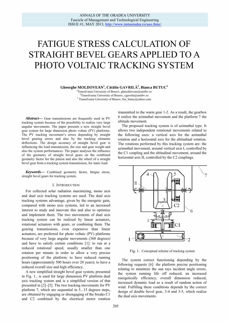
A new simplified straight bevel gear system, presented in Fig. 1., is used for large dimension PV platform dual axis tracking system and is a simplified version of that presented in [2]–[5]. The two tracking movements for PV platform 7, which are sequential in 5...15 degrees steps, are obtained by engaging or disengaging of the breaks C1 and C2 combined by the electrical motor rotation
transmitted to the warm gear 1-2. As a result, the gearbox 6 realize the azimuthal movement and the platform 7 the altitude movement.
The proposed tracking system is of azimuthal type. It allows two independent rotational movements related to the following axes: a vertical axis for the azimuthal rotation and a horizontal axis for the altitudinal rotation. The rotations performed by this tracking system are: the azimuthal movement, around vertical axis I, controlled by the C1 coupling and the altitudinal movement, around the horizontal axis II, controlled by the C2 couplings.
Fig. 1. Conceptual scheme of tracking system
The system correct functioning depending by the following requests [6]: the platform precise positioning relating to minimize the sun rays incident angle errors, the system running life off reduced, an increased energetically efficiency, overall dimension reduced, increased dynamic load as a result of random action of wind. Fulfilling these conditions depends by the correct design of double bevel gear, 3-4 and 3-5, which realize the dual axis movements.
FATIGUE STRESS CALCULATION OF STRAIGHT BEVEL GEARS APPLIED TO A
PHOTO VOLTAIC TRACKING SYSTEM
Gheorghe MOLDOVEAN
1, Cătălin GAVRILĂ
2, Bianca BUTUC
3
1Transilvania University of Brasov, [email protected] 2Transilvania University of Brasov, [email protected]
3 Transilvania University of Brasov, [email protected]
ANNALS OF THE ORADEA UNIVERSITY Fascicle of Management and Technological Engineering
ISSUE #1, MAY 2013, http://www.imtuoradea.ro/auo.fmte/
205
II. THEORETICAL ASPECTS To reduce the transmission errors, the straight bevel
gears need be high precision manufactured. Due to a many complex factor such as the large range of bearing vibration amplitudes, gearing manufacture tolerances, gearing contact deformations, gear bending deflections, shafts bending deflections and torsion deformations, bearing clearances, is difficult to avoid the gearing teeth impact and load concentration [7]. The straight bevel gear teeth contact is given by an elongated ellipse, the gear overall dimensions depending by the teeth contact length. Is absolutely needed that the contact patch to cover the entire teeth length for full load gearing. But, this is impossible because of the teeth manufacturing errors and also gearing assembling errors [8].
The straight bevel design request labored calculus, the needed time increased, prone to errors and repeated calculus and doubling the expenses. So, the straight bevels design quality influencing the gearing overall dimension and weight and also the transmission performances [9]. The straight bevel gear main stresses are contact and bending. Under the external loads, the gears and the platform structure can be damaged by the overloads and also by the material fatigue.
The straight bevel gear geometric parameters influence on the contact stress was analyzed in [10] and static bending stress was analyzed in [4]. For fatigue stress, the large number of loads (because of the wind repeated action) can damage the gear during time, even when these loads produced stresses not exceed the permissible root stress. From all the platform external loads (as wind, rain, snow, seismic, system weight), the most important is the wind action load. The straight bevel gear calculus is based on the calculus methods given by the ISO/TC 60 Gears Technical Committee, in the ISO 10300 international standard.
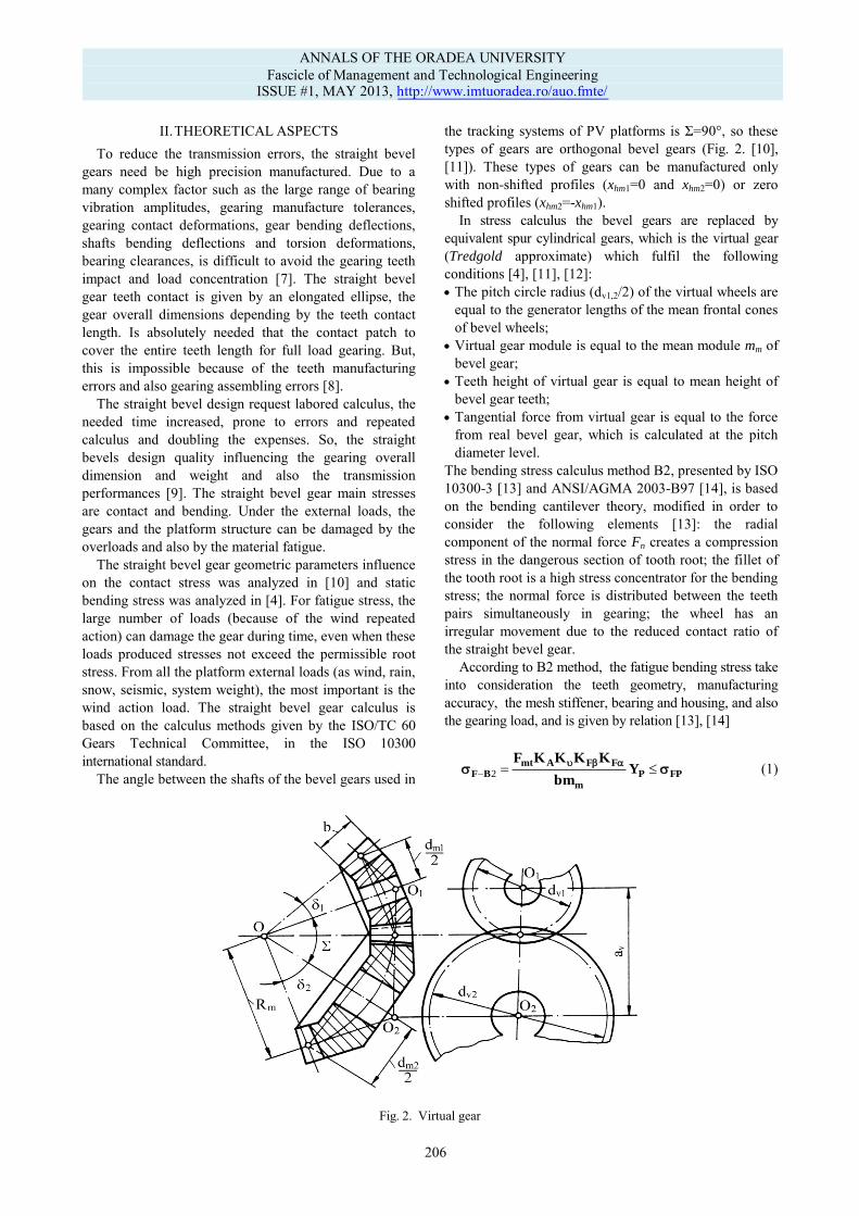
The angle between the shafts of the bevel gears used in
the tracking systems of PV platforms is Σ=90°, so these
types of gears are orthogonal bevel gears (Fig. 2. [10], [11]). These types of gears can be manufactured only with non-shifted profiles (xhm1=0 and xhm2=0) or zero shifted profiles (xhm2=-xhm1).
In stress calculus the bevel gears are replaced by equivalent spur cylindrical gears, which is the virtual gear (Tredgold approximate) which fulfil the following conditions [4], [11], [12]: The pitch circle radius (dv1,2/2) of the virtual wheels are
equal to the generator lengths of the mean frontal cones of bevel wheels;
Virtual gear module is equal to the mean module mm of bevel gear;
Teeth height of virtual gear is equal to mean height of bevel gear teeth;
Tangential force from virtual gear is equal to the force from real bevel gear, which is calculated at the pitch diameter level.
The bending stress calculus method B2, presented by ISO 10300-3 [13] and ANSI/AGMA 2003-B97 [14], is based on the bending cantilever theory, modified in order to consider the following elements [13]: the radial component of the normal force Fn creates a compression stress in the dangerous section of tooth root; the fillet of the tooth root is a high stress concentrator for the bending stress; the normal force is distributed between the teeth pairs simultaneously in gearing; the wheel has an irregular movement due to the reduced contact ratio of the straight bevel gear. According to B2 method, the fatigue bending stress take into consideration the teeth geometry, manufacturing accuracy, the mesh stiffener, bearing and housing, and also the gearing load, and is given by relation [13], [14]
FPPm
FFAmtBF Y
bm
KKKKF
2 (1)
Fig. 2. Virtual gear
ANNALS OF THE ORADEA UNIVERSITY Fascicle of Management and Technological Engineering
ISSUE #1, MAY 2013, http://www.imtuoradea.ro/auo.fmte/
206
where: 112 mmt dTF is nominal tangential force at reference cone at mid face width of pinion; KA – application factor; Kv – dynamic factor; KFβ – face load factor for bending stress; KFα – transverse load factor for bending stress; b – face width; mm – mean module.
Combined geometry factor YP is given by relation
2emJAP mmYYY , (2) where: YA is bevel gear adjustment factor; YJ – bevel geometry factor; me – outer module (standard for straight bevel gear).
Bevel geometry factor (B2 method) YJ is given by relation
e
mce
v
my
iN
KJ
m
m
b
b
d
r
Y
YY
02
, (3)
and bevel gear adjustment factor YA by relation
tan3
13.2N
N
fA
h
s
YY . (4)
Bevel gear factor YK depends by tooth thickness at
critical section 2sN, load height from critical section hN and tooth fillet radius at the mean section, rmf, and is given by relation
fK
Y
YY , (5)
where:
3
tan
1
3
2
h
N
N
N
e
s
h
s
mY
(6)
is tooth form factor;
O
N
N
M
mf
Nf
h
s
r
sLY
22 (7)
is stress concentration and stress correction factor; L, M and O are empirical constants used in stress correction formula.
The tooth fillet radius at the mean section rmf is given by relation
0
0
2
0
2a
afmv
afmmf
hd
hr
(8)
where hfm is mean dedendum; a0 – cutter edge radius; dv – reference diameter of virtual cylindrical gear.
Other notations used in the above relations have the following meanings: N – load sharing ratio; Yi – inertia factor; rmy0 – mean transverse radius to point of load application; dv – reference diameter of virtual cylindrical gear; bce – calculated effective face width; h – normal pressure angle at point of load application on the tooth centerline. All of these factors can be obtained following ISO 10300-3 [13] and ANSI-AGMA 2003-B97 [14] prescriptions.
The tooth root stress calculus need to be done separately for pinion and also for wheel. For an increased degree of generality, all the geometrical elements are determined related to mean module mm.
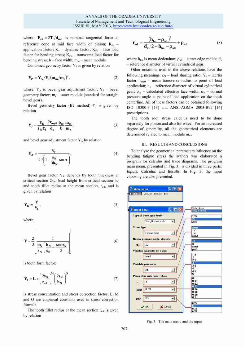
III. RESULTS AND CONCLUSIONS To analyze the geometrical parameters influence on the
bending fatigue stress the authors was elaborated a program for calculus and trace diagrams. The program main menu, presented in Fig. 3., is divided in three parts: Inputs, Calculus and Results. In Fig. 3, the input choosing are also presented.
Fig. 3. The main menu and the input
ANNALS OF THE ORADEA UNIVERSITY Fascicle of Management and Technological Engineering
ISSUE #1, MAY 2013, http://www.imtuoradea.ro/auo.fmte/
207
In Calculus section, based on the ISO 10300-1 [15], ISO 10300-3 [13] and ANSI/AGMA 2003-B97 [14] relations, the values of Y1,2, YA1,2, YJ1,2 and YP1,2 factors are determined. The user can choose the output of these values, as table or as diagram, in Output section, like shown in Fig. 4.
Because is hard to predict the variation of wind speed, which load finally the tracking system bevel gears, the fatigue calculus becomes very important and required. In this way, the gear damages because of material fatigue can be avoided.
So, it is necessary to analyze geometrical parameters
influence on the bending fatigue stress, because these results are real useful for PV tracking designers.
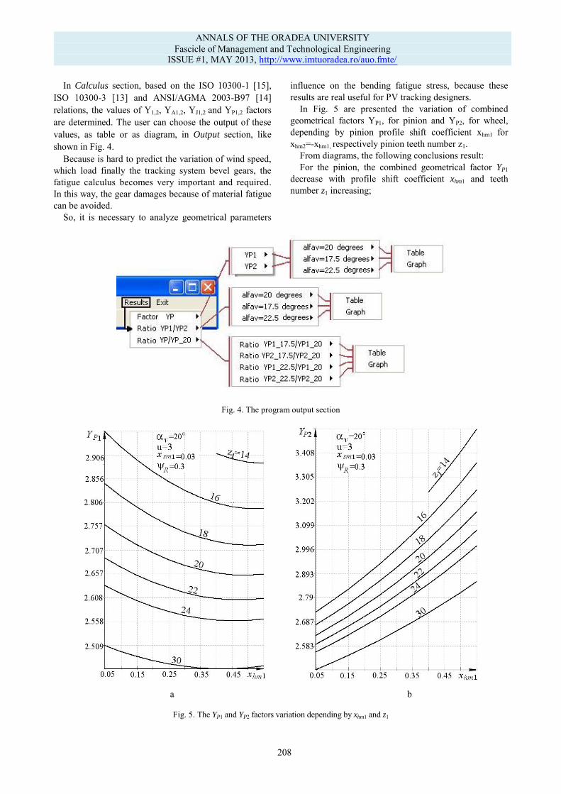
In Fig. 5 are presented the variation of combined geometrical factors YP1, for pinion and YP2, for wheel, depending by pinion profile shift coefficient xhm1 for xhm2=-xhm1, respectively pinion teeth number z1.
From diagrams, the following conclusions result: For the pinion, the combined geometrical factor YP1
decrease with profile shift coefficient xhm1 and teeth number z1 increasing;
Fig. 4. The program output section
a b
Fig. 5. The YP1 and YP2 factors variation depending by xhm1 and z1
ANNALS OF THE ORADEA UNIVERSITY Fascicle of Management and Technological Engineering
ISSUE #1, MAY 2013, http://www.imtuoradea.ro/auo.fmte/
208
For the pinion, the combined geometrical factor YP1 decrease with profile shift coefficient xhm1 and teeth number z1 increasing;
For the wheel, the combined geometrical factor YP2 increase with profile shift coefficient xhm1 increasing and also decrease with teeth number z1 increasing; the increasing of combined factor YP2 is more than the decrease of the combined factor YP1 (as example, for z1=22 teeth and xhm1=0.4 related to xhm1=0.05, YP1 decrease with 3.2%, and YP2 increase with 19%);
The YP2 factor increasing is explained by negative value of wheel profile shift coefficient, so the teeth width in dangerous section is decreased related to the pinion dangerous section which increase because xhm1>0.
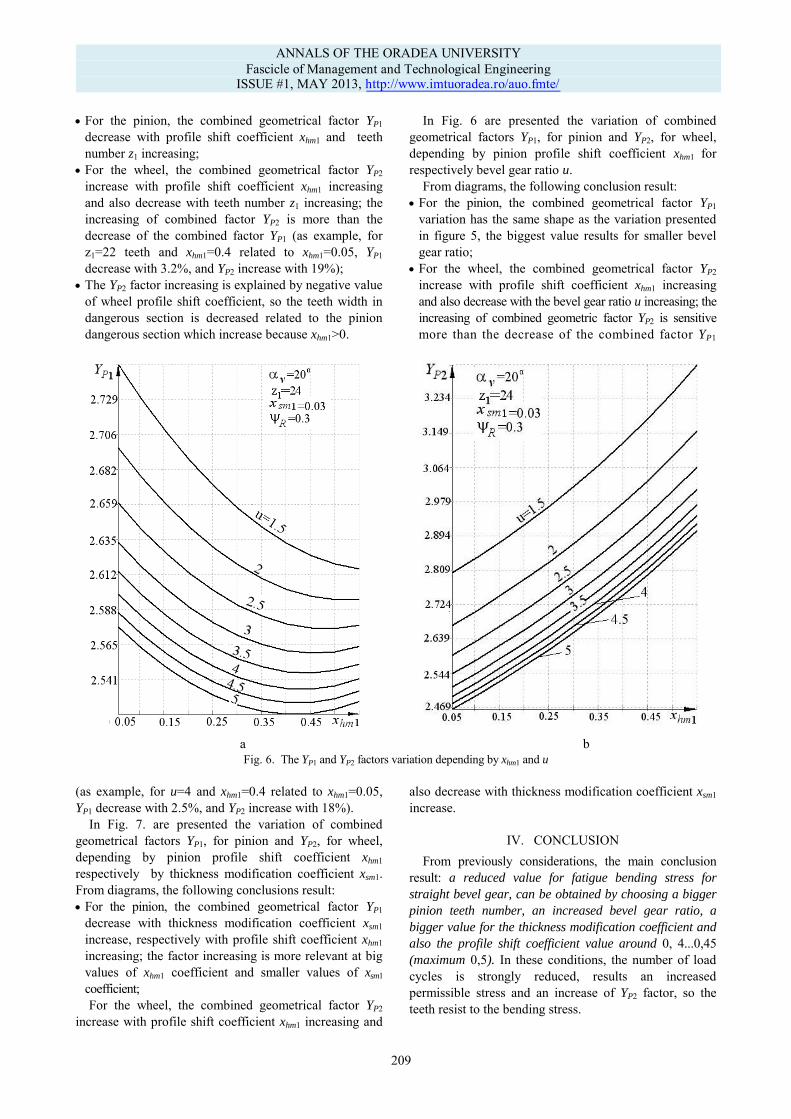
In Fig. 6 are presented the variation of combined geometrical factors YP1, for pinion and YP2, for wheel, depending by pinion profile shift coefficient xhm1 for
respectively bevel gear ratio u. From diagrams, the following conclusion result:
For the pinion, the combined geometrical factor YP1 variation has the same shape as the variation presented in figure 5, the biggest value results for smaller bevel gear ratio;
For the wheel, the combined geometrical factor YP2 increase with profile shift coefficient xhm1 increasing and also decrease with the bevel gear ratio u increasing; the increasing of combined geometric factor YP2 is sensitive more than the decrease of the combined factor YP1
a b
Fig. 6. The YP1 and YP2 factors variation depending by xhm1 and u
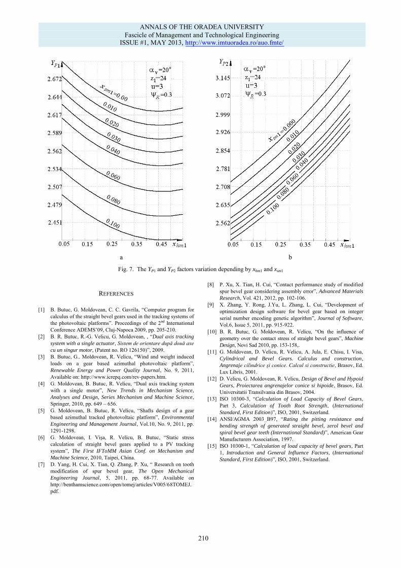
(as example, for u=4 and xhm1=0.4 related to xhm1=0.05, YP1 decrease with 2.5%, and YP2 increase with 18%). In Fig. 7. are presented the variation of combined geometrical factors YP1, for pinion and YP2, for wheel, depending by pinion profile shift coefficient xhm1
respectively by thickness modification coefficient xsm1. From diagrams, the following conclusions result: For the pinion, the combined geometrical factor YP1
decrease with thickness modification coefficient xsm1 increase, respectively with profile shift coefficient xhm1 increasing; the factor increasing is more relevant at big values of xhm1 coefficient and smaller values of xsm1 coefficient; For the wheel, the combined geometrical factor YP2
increase with profile shift coefficient xhm1 increasing and
also decrease with thickness modification coefficient xsm1 increase.
IV. CONCLUSION From previously considerations, the main conclusion
result: a reduced value for fatigue bending stress for
straight bevel gear, can be obtained by choosing a bigger
pinion teeth number, an increased bevel gear ratio, a
bigger value for the thickness modification coefficient and
also the profile shift coefficient value around 0, 4...0,45
(maximum 0,5). In these conditions, the number of load cycles is strongly reduced, results an increased permissible stress and an increase of YP2 factor, so the teeth resist to the bending stress.
ANNALS OF THE ORADEA UNIVERSITY Fascicle of Management and Technological Engineering
ISSUE #1, MAY 2013, http://www.imtuoradea.ro/auo.fmte/
209
a b
Fig. 7. The YP1 and YP2 factors variation depending by xhm1 and xsm1
REFERENCES [1] B. Butuc, G. Moldovean, C. C. Gavrila, “Computer program for
calculus of the straight bevel gears used in the tracking systems of the photovoltaic platforms”. Proceedings of the 2nd International Conference ADEMS’09, Cluj-Napoca 2009, pp. 205-210.
[2] B. R. Butuc, R.-G. Velicu, G. Moldovean, , “Dual axis tracking
system with a single actuator, Sistem de orientare după două axe
cu un singur motor, (Patent no. RO 126150)”, 2009. [3] B. Butuc, G.. Moldovean, R. Velicu, “Wind and weight induced
loads on a gear based azimuthal photovoltaic platform”,
Renewable Energy and Power Quality Journal, No. 9, 2011, Available on: http://www.icrepq.com/rev-papers.htm.
[4] G. Moldovean, B. Butuc, R. Velicu, “Dual axis tracking system with a single motor”, New Trends in Mechanism Science,
Analyses and Design, Series Mechanism and Machine Science, Springer, 2010, pp. 649 – 656.
[5] G. Moldovean, B. Butuc, R. Velicu, “Shafts design of a gear based azimuthal tracked photovoltaic platform”, Environmental
Engineering and Management Journal, Vol.10, No. 9, 2011, pp. 1291-1298.
[6] G. Moldovean, I. Vişa, R. Velicu, B. Butuc, “Static stress calculation of straight bevel gears applied to a PV tracking system”, The First IFToMM Asian Conf. on Mechanism and
Machine Science, 2010, Taipei, China. [7] D. Yang, H. Cui, X. Tian, Q. Zhang, P. Xu, “ Research on tooth
modification of spur bevel gear, The Open Mechanical
Engineering Journal, 5, 2011, pp. 68-77. Available on http://benthamscience.com/open/tomej/articles/V005/68TOMEJ.pdf.
[8] P. Xu, X. Tian, H. Cui, “Contact performance study of modified spur bevel gear considering assembly error”, Advanced Materials
Research, Vol. 421, 2012, pp. 102-106. [9] X. Zhang, Y. Rong, J.Yu, L. Zhang, L. Cui, “Development of
optimization design software for bevel gear based on integer serial number encoding genetic algorithm”, Journal of Software, Vol.6, Issue 5, 2011, pp. 915-922.
[10] B. R. Butuc, G. Moldovean, R. Velicu, “On the influence of
geometry over the contact stress of straight bevel gears”, Machine
Design, Novi Sad 2010, pp. 153-158,. [11] G. Moldovean, D. Velicu, R. Velicu, A. Jula, E. Chisu, I. Visa,
Cylindrical and Bevel Gears. Calculus and construction, Angrenaje cilindrice şi conice. Calcul si constructie, Brasov, Ed. Lux Libris, 2001.
[12] D. Velicu, G. Moldovean, R. Velicu, Design of Bevel and Hypoid
Gears, Proiectarea angrenajelor conice si hipoide, Brasov, Ed. Universitatii Transilvania din Brasov, 2004.
[13] ISO 10300-3, “Calculation of Load Capacity of Bevel Gears, Part 3, Calculation of Tooth Root Strength, (International
Standard, First Edition)”, ISO, 2001, Switzerland. [14] ANSI/AGMA 2003_B97, “Rating the pitting resistance and
bending strength of generated straight bevel, zerol bevel and
spiral bevel gear teeth (International Standard)”, American Gear
Manufacturers Association, 1997. [15] ISO 10300-1, “Calculation of load capacity of bevel gears, Part
1, Introduction and General Influence Factors, (International
Standard, First Edition)”, ISO, 2001, Switzerland.
ANNALS OF THE ORADEA UNIVERSITY Fascicle of Management and Technological Engineering
ISSUE #1, MAY 2013, http://www.imtuoradea.ro/auo.fmte/
210


![Bevel Gears in ProE[1]](https://img.pdfslide.net/doc/110x75/543da9fbb1af9f3d0a8b4920/bevel-gears-in-proe1.jpg)