Embed Size (px)
Citation preview

___ 9 1 APR1 998
REPORT DOCUMENTATION PAGE AFRL-SR-BL.TR.98.
Public Reporting burden for this collection of information is estimated to average 1 hour per respor Usearching existing data sources, gathering and maintaining the data needed, and completing andi Uregarding this burden estimates or any other aspect of this collection of information. including suggestions nu .Headquarters Services. Directorate for information Operations and Reports, 1215 Jefferson Davis Highway, Suite 1204. Arlington. tothe Office of Management and Budget, Paperwork Reduction Project (0704-0188,) Washington, DC 20503.1. AGENCY USE ONLY ( Leave Blank) 2. REPORT DATE 3. REPORT TYPE AND DATES COVERED
March 23, 1998 Final Report (1 Aug 95 to 31 Jul 97)
4. TITLE AND SUBTITLE 5. FUNDING NUMBERS
High Temperature Environmental Test Facility For Uniaxial F49620-95- 1-04 70Testing Under Cyclic Loading6. AUTHOR(S)Shankar M.L. Sastry and K. L. Jerina
7. PERFORMING ORGANIZATION NAME(S) AND ADDRESS(ES) 8. PERFORMING ORGANIZATIONWashington University REPORT NUMBERMaterials Research Laboratory Box 1087One Brookings DriveSt. Louis, MO 631309. SPONSORING / MONITORING AGENCY NAME(S) AND ADDRESS(ES) 10. SPONSORING / MONITORINGAir Force Office of Scientific Research / NA AGENCY REPORT NUMBER110 Duncan Avenue Suite B 115Boiling AFB, Washington D.C., 20332-808011. SUPPLEMENTARY NOTES
The views, opinions and/or findings contained in this report are those of the author(s) and should not beconstrued as an official Department of the Air Force position, policy or decision, unless so designated by thedocumentation.
12 a. DISTRIBUTION / AVAILABILrTY STATEMENT 12 b. DISTRIBUTION CODE
Approved for public release; distribution unlimited.
13. ABSTRACT (Maximum 200 words)
A versatile test facility is described for the measurement of tensile, compressive, fracture toughness,mechanical fatigue, and thermomechanical fatigue properties of metals, intermetallics, ceramics, andcomposites at 25 to 2000 'C in vacuum, inert, and reducing atmospheres. The test system consists of a fullyautomated computer controlled axial load frame; a test chamber designed for interchangeable heatingelements for different environments, grips for different types of loading and thermal histories, and ceramic rodextensometry.
The facility overcomes a serious deficiency in test facilities and procedures to obtain material property data forthe design of components subjected to high cycle fatigue loading conditions, thermomechanical fatigue,fatigue crack propagation in controlled atmospheres. The instrumentation fills the need to provide thedesigners with reliable and reproducible mechanical property data obtained under simulated loadingconditions and operational environments. Damage tolerance concepts and predictive models that accuratelyreflect the combined effects of loading conditions and environmental species can be developed for qualificationof mature and emerging high temperature materials for hypersonic/high speed vehicle structures andadvanced aircraft engines.
14. SUBJECT TERMS 15. NUMBER OF PAGESfatigue, high cycle fatigue, thermomechanical fatigue, fatigue crack growth 19
16. PRICE CODE
17. SECURITY 18. SECURITY 19. SECURITY1CLAS IF ITION 20. LIMITATION OFCLASSIFICATION CLASSIFICATION OF ABSTRACT ABSTRACT
OR REPORT ON THIS PAGE UNCLASSIFIEDUNCLASSIIE UNCLASSIFIED UL
NSN 7540-01-280-5500 Standard Form 298(Rev.2-89)
Prescribed by ANSI Std. 239-18298-102 19980505 048

HIGH TEMPERATURE ENVIRONMENTAL TEST FACILITY FOR UNIAXIALTESTING UNDER CYCLIC LOADING
FINAL TECHNICAL REPORTGrant No. F49620-95- 1-04 70
Submitted to
Air Force Office of Scientific Research / NA110 Duncan Avenue Suite B 115
Boiling AFB, Washington D.C., 20332-8080
Attention: Major Brian Sanders, Program OfficerMs. Jennifer Bell, Grants Officer
by
Prof. Shankar M.L. Sastry (Principal Investigator) andProf. K. L. Jerina (Co-Principal Investigator)
Washington UniversityOne Brookings DriveSt. Louis, MO 63130
March 23, 1998
r)p.'o)v td f c r I.,. c r ni on %.•dl~tk ibu'tion uiA!o

TABLE OF CONTENTS
INTRODUCTION
DESCRIPTION OF THE HIGH FREQUENCY FATIGUE SYSTEM 2Fatigue SystemSystem ControllerGripsDynamic Load CalibrationChamberPhysical Test KitVacuum SystemProcess Gas SystemCooling SystemPower SupplyTemperature Control
RESEARCH PROJECTS USING THE HCF SYSTEM 12Aircraft Structural Alloys
IMPACT OF THE HCF SYSTEM AND FUTURE RESEARCH 12High Speed VehiclesTurbine Engine TechnologyThermomechanical FatigueTraining of Future Scientists And Engineers
REFERENCES 17

INTRODUCTION
A versatile test facility is described for the measurement of tensile, compressive, fracturetoughness, mechanical fatigue, and thermomechanical fatigue properties of metals, intermetallics,ceramics, and composites at 25 to 2000 'C in vacuum, inert, and reducing atmospheres. The testsystem consists of a fully automated computer controlled axial load frame; a test chamber designedfor interchangeable heating elements for different environments, grips for different types of loadingand thermal histories, and ceramic rod extensometry.
The facility is being used for experimental evaluation of mechanical properties that characterize thebehavior of conventional and emerging materials for aerospace structures under a broad range ofconditions representative of those encountered in service. The instrumentation is a key element inthe development of (1) relationships between the microscopic structure and the macroscopicstructural response of high temperature materials in inert and aggressive environments, (2) uniquecombined thermal, environmental, and mechanical testing methodology now possible with modeminstrumentation, and (3) testing methodology for low ductility intermetallics.
The facility overcomes a serious deficiency in test facilities and procedures to obtain materialproperty data for the design of components subjected to high cycle fatigue loading conditions,thermomechanical fatigue, fatigue crack propagation in controlled atmospheres. Theinstrumentation fills the need to provide the designers with reliable and reproducible mechanicalproperty data obtained under simulated loading conditions and operational environments. Damagetolerance concepts and predictive models that accurately reflect the combined effects of loadingconditions and environmental species can be developed for qualification of mature and emerginghigh temperature materials for hypersonic/high speed vehicle structures and advanced aircraftengines.
Our group at Washington University has active research programs in the synthesis, processing, andcharacterization of advanced high performance structural and functional materials, which requirestate-of-the-art mechanical property measurements. Washington University, MTS and MRF havedesigned and built a high frequency - high temperature - environmental fatigue system underAFOSR Grant No. F49620-95- 1-04 70. This report describes the system and the research projectsin which the equipment is being used.
Significant interest has developed recently in. high cycle fatigue testing of aircraft engine structuralmaterials. This has been driven by the US Air Force, which is in search of new methodologies forlife prediction and design against high cycle fatigue failure. Typically, fatigue problems emanatefrom a damage site, such as a compressor blade that has been damaged. Fatigue failure occurswhen these damaged sites lead to crack propagation, driven by vibration stresses, at high meanstresses but low stress amplitudes. Since the vibration frequencies are high and the stressamplitudes are low, data is scarce. Fatigue lifetimes of up to one billion cycles are of interest.These lifetimes are difficult to attain in standard testing machines at normal testing frequency onthe order of 10 Hz. The High Cycle Fatigue machine described herein is capable of operating atfrequencies of 1000 Hz or two orders of magnitude greater than many conventional machines.Obtaining fatigue life data in the one billion-cycle regime is now possible. In response to these
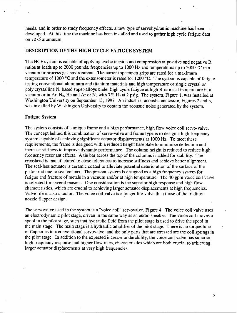
needs, and in order to study frequency effects, a new type of servohydraulic machine has beendeveloped. At this time the machine has been installed and used to gather high cycle fatigue dataon 7075 aluminum.
DESCRIPTION OF THE HIGH CYCLE FATIGUE SYSTEM
The HCF system is capable of applying cyclic tension and compression at positive and negative Rratios at loads up to 2000 pounds, frequencies up to 1000 Hz and temperatures up to 2000 0C in avacuum or process gas environment. The current specimen grips are rated for a maximumtemperature of 1000 'C and the extensometer is rated for 1200 'C. The system is capable of fatiguetesting conventional aluminum and titanium materials and high temperature or single crystal orpoly crystalline Ni based super-alloys under high cycle fatigue at high R ratios at temperature in avacuum or in Ar, N2, He and Ar or N2 with 7% H2 at 2 psig. The system, Figure 1, was installed atWashington University on September 15, 1997. An industrial acoustic enclosure, Figures 2 and 3,was installed by Washington University to contain the acoustic noise generated by the system.
Fatigue System
The system consists of a unique frame and a high performance, high flow voice coil servo-valve.The concept behind this combination of servo-valve and frame type is to design a high frequencysystem capable of achieving significant actuator displacements at 1000 Hz. To meet theserequirements, the frame is designed with a reduced height baseplate to minimize deflection andincrease stiffness to improve dynamic performance. The column height is reduced to reduce highfrequency resonant effects. A tie bar across the top of the columns is added for stability. Thecrosshead is manufactured to close tolerances to increase stiffness and achieve better alignment.The seal-less actuator is ceramic coated to alleviate potential deterioration of the surface of thepiston rod due to seal contact. The present system is designed as a high frequency system forfatigue and fracture of metals in a vacuum and/or at high temperature. The 40 gpm voice coil valveis selected for several reasons. One consideration is the superior high response and high flowcharacteristics, which are crucial to achieving larger actuator displacements at high frequencies.Valve life is also a factor. The voice coil valve is a longer life valve than those of the traditionnozzle flapper design.
The servovalve used in the system is a "voice coil" servovalve, Figure 4. The voice coil valve usesan electrodynamic pilot stage, driven in the same way as an audio speaker. The voice coil moves aspool in the pilot stage, such that hydraulic fluid from the pilot stage is used to drive the spool inthe main stage. The main stage is a hydraulic amplifier of the pilot stage. There is no torque tubeor flapper as in a conventional servovalve, and the only parts that are stressed are the coil springs inthe pilot stage. In addition to the expected increase in durability, the voice coil valve has superiorhigh frequency response and higher flow rates, characteristics which are both crucial to achievinglarger actuator displacements at very high frequencies.
2

al fn---- -- -- -- -- - -
- - -
LEFT_ SID FRONT _ _HTSIDE
Washington University HCF System with Vacuum Process Gas Chamber (10/30/97)
Figure 1. Schematic diagram of high cycle fatigue environmental system.
Figure 2. Acoustic enclosure and control console of the High Cycle Fatigue System.
3

ýA'
Figure 3. Interior of sound enclosure showing the vacuum and power controller on the leftand the load frame on the right.
Figure 4. The voice coil three stage servo valve.
4

System Controller
The digital system which controls traditional servohydraulics also controls the HCF system; theonly modifications are the acceleration compensation, and the use of an adaptive control schemewhich yields steady-state load control at 1000 Hz. The digital controller utilizes a phase amplitudecompensator (PAC) to detect and correct amplitude roll-off and phase lag in sinusoidal commandwaveforms. The TestStar II controller provides multi channel control for advanced applicationssuch as thermal mechanical fatigue and simulation. The controller features include additionalcontrol, data acquisition, and input/output capabilities over the single channel systems. TestStar IIhas an intuitive user interface, which makes it suited for demanding applications.
TestStar II is an automated digital control system used to control closed loop servo hydraulictesting systems with up to four servo-loops. TestStar uses graphical, mouse driven system softwareto set up and manage tests, and collect data. Time-critical processes such as closed loop control,limit detection and data acquisition take place in the controller firmware. TestStar II can beconfigured on dynamic test systems. One TestStar chassis can control up to four channelssimultaneously. This feature makes TestStar ideal for complex testing such as thermal mechanicalfatigue. The TestStar II controller system includes three major functional elements: (1) TestStar IIsystem software operating on a personal computer with Windows/NT. (2) Real-time firmwarefunctions operating inside the TestStar HIs digital controller chassis. and (3) A load unit controlpanel provides the capability to manually control hydraulic fluid power and actuator position. Inaddition to the basic controller elements, application software is available to provide testcapabilities for a variety of applications. TestWare-SX is a flexible multi-purpose softwareapplication used to create and run tests. Through a series of software windows, tests are designedin a systematic manner, with test system function generation and data acquisition requirementsdefined for each part of the test. Automatically triggered limit detectors, and custom designedoperator-triggered event detectors are configured through TestWare-SX. Command signals forexternal devices, such as temperature controllers can be generated. Test data are stored in astandard text format for post-test analysis. Enhancements to TestWare-SX include run-timeplotting, advanced function generation, high speed data acquisition, data monitoring for trends, andrun time ramp control for incremental stepping toward indeterminate end levels. Other applicationsoftware packages such as Low Cycle Fatigue, High Cycle Fatigue, Fatigue Crack Growth,Fracture Toughness, and TestWorks for Static Applications are available.
A personal computer user interface replaces hardware knobs and buttons, reducing operator errors.In addition, an optional manual actuator positioning control protects the specimen and speedstesting. A selection of pre-configured test system detector actions can be set up. On triggering alimit, error or under-peak, actions are implemented by microprocessors located inside the TestStarchassis for the fastest response to save valuable specimens or prevent test equipment damage.Customized controlled shutdown sequence can be implemented, which can be particularly valuablein protecting complex and expensive specimens. Multitasking software allows simultaneousviewing and adjustment of on-screen data read-outs, tuning controls, operator event triggers, run-time plots and run-time rate controls while the test is in progress. Manually operated actuatorpositioning control protects the specimen and speeds testing. The actuator positioning controloperates in a load-limited stroke mode to rapidly position the actuator while keeping the forceapplied to within the pre-set limit. Multitasking allows analysis data, generation of reports, or
5

network operations on the PC while a test is running. TestStar II can store and retrieve anunlimited number of user-defined system and test set-ups. Flexible signal conditioning andexternal signal input capability allows other transducers and signal conditioners. Data can becollected from sensors conditioned by existing amplifiers. In addition, on-board TestStar signalconditioners accept signals from almost any transducers such as bonded strain gages formeasurement or control. TestStar II provides a convenient built-in bridge completion resistorfeature that simplifies working with strain gages, of particular interest when multiple gages may beused for specimen damage monitoring.
The basic TestStar chassis has 13 available slots for signal conditioners in a single servo-loopconfiguration, as well as inputs for up to eight externally conditioned high-level sensor signals.Auto tuning quickly and reliably sets up PID parameters. Control mode switches can be madebetween any internally or externally conditioned sensor or calculated signal. Firmware in thecontroller-resident high-speed processors is initialized by the TestStar II system software. Newcontroller capabilities are provided by system software updates that include new processorfirmware. Data acquisition processes are easy to set up. Timed, peak-valley, and level crossingcan collect data on all channels at up to 5 kHz sampling rate. Data is buffered (using one of severalbuffering options) before they are sent to disk. Thus avoiding excessive data collection, savingdisk space and making post-test analysis much easier. Transient test events are accurately captured.Data skew between channels is eliminated for more accurate post-test analysis. Simultaneoussample and hold data acquisition for all data acquisition channels eliminates phase shifting of databetween large numbers of channels, allowing simplified post-test phase angle measurement andmuch easier data analysis, including material damping calculations. A high-speed controllerresident data acquisition option allows single channel acquisition rates of 50 kHz.
Fast and accurate calculations are made inside the TestStar chassis. Microprocessors used forcalculations are fully integrated with other high-speed controller processors inside the TestStarchassis for real-time calculated signal control, limit detection and data acquisition. Calculatedvariable control tests are easy to set up, without complicated programming. Equations are typedinto system software, combining sensor signals in the desired way for control feedback. Minimumand maximum values expected for the calculated parameter, determined by the user, are entered forlimit detection. Calculation constants, for simplification of repeated mathematical operations, canbe user-defined. Up to 8 calculated signals can be created using built-in linear, trigonometric,exponential or logarithmic math functions by combining any internal, calculated, or externallyconnected sensor signals, for new test capabilities such as post failure test control with calculatedfeedback. Calculations are made in firmware at the closed loop update rate. True stress and strain,energy, and averaged value of multiple sensors are examples of the calculated control modepossibilities. This feature includes high-speed circular buffers that store the previous 100 datapoints from any connected sensor or calculated signal. For example, stored displacement and timedata can be used to define strain rate signals. Calculated inputs can be a tool for event or limitdetection. A calculated parameter can be continuously monitored and used to trigger a controlmode switch, a new test sequence or emergency shutdown. For example, real time elastic moduluscan be calculated using buffered strain and load data. This signal can be monitored to detectspecimen stiffness change, and upon triggering an event detector, used to terminate a test.
6
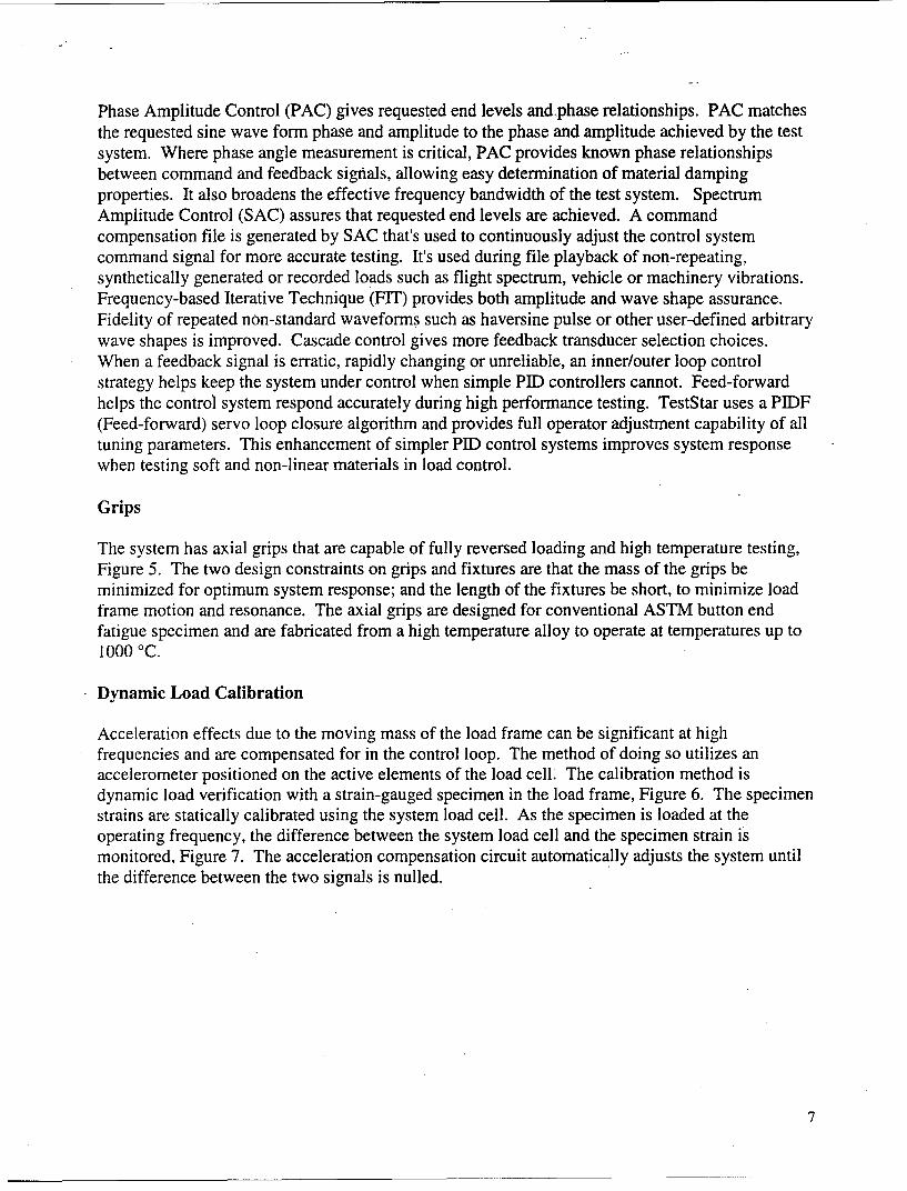
Phase Amplitude Control (PAC) gives requested end levels and.phase relationships. PAC matchesthe requested sine wave form phase and amplitude to the phase and amplitude achieved by the testsystem. Where phase angle measurement is critical, PAC provides known phase relationshipsbetween command and feedback signals, allowing easy determination of material dampingproperties. It also broadens the effective frequency bandwidth of the test system. SpectrumAmplitude Control (SAC) assures that requested end levels are achieved. A commandcompensation file is generated by SAC that's used to continuously adjust the control systemcommand signal for more accurate testing. It's used during file playback of non-repeating,synthetically generated or recorded loads such as flight spectrum, vehicle or machinery vibrations.Frequency-based Iterative Technique (FIT) provides both amplitude and wave shape assurance.Fidelity of repeated non-standard waveforms such as haversine pulse or other user-defined arbitrarywave shapes is improved. Cascade control gives more feedback transducer selection choices.When a feedback signal is erratic, rapidly changing or unreliable, an inner/outer loop controlstrategy helps keep the system under control when simple PID controllers cannot. Feed-forwardhelps the control system respond accurately during high performance testing. TestStar uses a PIDF(Feed-forward) servo loop closure algorithm and provides full operator adjustment capability of alltuning parameters. This enhancement of simpler PID control systems improves system responsewhen testing soft and non-linear materials in load control.
Grips
The system has axial grips that are capable of fully reversed loading and high temperature testing,Figure 5. The two design constraints on grips and fixtures are that the mass of the grips beminimized for optimum system response; and the length of the fixtures be short, to minimize loadframe motion and resonance. The axial grips are designed for conventional ASTM button endfatigue specimen and are fabricated from a high temperature alloy to operate at temperatures up to1000 °C.
Dynamic Load Calibration
Acceleration effects due to the moving mass of the load frame can be significant at highfrequencies and are compensated for in the control loop. The method of doing so utilizes anaccelerometer positioned on the active elements of the load cell. The calibration method isdynamic load verification with a strain-gauged specimen in the load frame, Figure 6. The specimenstrains are statically calibrated using the system load cell. As the specimen is loaded at theoperating frequency, the difference between the system load cell and the specimen strain ismonitored, Figure 7. The acceleration compensation circuit automatically adjusts the system untilthe difference between the two signals is nulled.
7

Figure 5. High temperature tension compression grips for ASTM button end specimens.
SS
Figure 6. Strain gaged alignment specimen.
Figure 7. Computer display of alignment data..

Chamber
The furnace is a Front Loading, Physical Testing Furnace, with a usable work zone of 3.5" dia. x3.0" high, and a maximum operating temperature of 2000 'C. The furnace chamber, Figures 8 and9, has the following features:
Rectangular double walled water-cooled 304L stainless steel.Polished to a #4 finish on the inside and outside surfaces.Electropolished after all machining and welding, to clean all surfaces thoroughly.Ports to accommodate the temperature thermocouples, vacuum sensors, vacuum system,water feed-through for the extensometer, RGA, blanked off port for electrical feed-through,Left hand hinged front opening door.1/2" dia. rotating sight window on the front door, centered to the hot zone.The hot zone is a 180" split design, with Tungsten/molybdenum shields and tungsten meshheating element.There are four water-cooled copper power feed through, which supply power to theelement.The chamber is large enough to house extensometer and includes extensometer mountingbrackets.
Physical Test Kit
Two tension/compression cold rods, these rods are water-cooled centerless ground 440stainless steel hardened to Rc60.Top stainless steel welded bellows for alignment, this assembly also seals the top water-cooled rod by an o-ring seal.Bottom stainless steel welded bellows for alignment.Lower double Lip Seal housing assembly, this assembly seals the lower cold rod to allow itto oscillate with a frequency of up to 1000 Hz.
Vacuum System
Vacuum system performance is capable of 10-5 TORR vacuum range in high vacuum mode. Thehigh vacuum pumping system, Figure 10, consists of the following:
Varian VHS-Diffusion pump.VRC electro-pneumatic high vacuum gate angle valve.Varian cold trap (baffle), cooled with a non-CFC refrigerant.An electro-pneumatic diffusion pump foreline and chamber roughing valves.A rotary vane dual stage mechanical pump with exhaust filter.All stainless steel manifold to connect these component together.Varian senTORR Cold Cathode Gauge controller with associated vacuum sensors.Graphic display panel with switches for operating the vacuum system.
9

Figure 8. Front of the environmental chamber showing sight glass and power cables.
Figure 9. Back of the environmental chamber showing ports and power cables.
Figure 10. Vacuum system diffusion pump.
10

Process Gas System
The gas system performance is 2 psig maximum pressure (Ar, N, He and Ar or N with amaximum of 7% H.
A solenoid operated gas inlet valve.A gas Flowmeter with flow control valve.A 2 psig factory set relief valve.A compound gauge (30" Hg. x 30 psig).
Cooling System
The water cooling system is designed to cool all components to 150 'F and includes thefollowing:
Water strainer on the inlet manifoldAn inlet manifold with a number of circuits to cool all components sufficiently.All hoses necessary to connect the components to the manifold.A ball valve on each circuit of the drain manifold.Water flow system interlock switch on the main drain.
Power Supply
The power supply is designed to accommodate an operating temperature of 2000 'C."A main circuit breaker is used as a main power disconnect and over current protection."A contactor which turns power onto the element or to disconnect power because ofinterlock.An SCR which modulates the power to the elements in a reliable and accurate fashion.A three phase to two-phase main step-down transformer.Two volt and two ammeters to monitor the power the furnace is using.Water-cooled power cables in order to carry the high current and provide cooling for thecopper power feed through.An auxiliary control transformer.Hot zone power on and off pushbuttons.
Temperature Control
Honeywell temperature programmer / controller. The input to this instrument is a Type"C" thermocouple with a range of 0-2000 °C.Honeywell hi-limit controller. The input to this instrument is a type "C" thermocouple.Varian vacuum gauge controller to control the operation of the high-vacuum system.Allen-Bradley Controller to control all the logic inherent to the furnace operation.
11

RESEARCH PROJECTS USING THE HCF SYSTEM
Aircraft Structural Alloys
A robust high cycle fatigue analysis method must be able to correlate the data generated from allfour test methods: axial constant amplitude, beam bending constant amplitude, axial random andbeam bending narrow band random. For example, the methodology must be able to use constantamplitude data to predict the fatigue life of beams exposed to random loads in bending. Thefollowing tasks will be used to systematically develop this correlation procedure. A literaturereview of available high cycle fatigue test data will be completed for selected alloys. This willcover axial tension, rotating beam, and vibrating beam fatigue data. The data will include da/dNversus AK crack growth data and strain-life data. Both sets of data are needed for correlatingstrain-life crack initiation predictions with crack growth based analysis. A significant databaseexists at Boeing - St. Louis from previous combined buffet/maneuver load and acoustic fatiguestudies.
Supplement the available data with a series of high frequency tests in constant amplitude using theWashington University facility. The tests will be completed at room temperature and at elevatedtemperature. This will include generating da/dN versus AK crack growth curves and strain-lifedata. The da/dN data generation will focus on defining the lower part of the curve below 10-7
inch/cycle in order to verify threshold stress intensity factors for large cracks. Part of the task willevaluate short crack behavior and its effect on the lower part of the da/dN curve. Use the availableand generated constant amplitude data to predict the fatigue life of beam specimens tested underrandom bending and random axial vibration loads. Crack growth based analysis using fracturemechanics and equivalent initial flaw sizes will be used to correlate the constant amplitude beambending and axial fatigue test data. Equivalent initial flaw sizes determined from this analysis willbe compared with the size of metallurgical flaws from which the cracks are found to develop todetermine if a physical correlation can be established. The fracture mechanics analysis will useavailable crack growth retardation models coupled with short crack analysis methodology.
Using the results of the correlation between axial and bending fatigue tests, use constant amplitudebending fatigue test data to predict axial, variable amplitude, spectrum fatigue failures. Verify thepredictions by testing a series of axial test coupons under variable amplitude, spectrum fatigue atWashington University. Comparisons will also be made with other available beam random fatiguetest data. This project was initiated on January 1, 1998 to study 7075 and 7050 aluminum alloysfor the Boeing Company.
IMPACT OF THE HCF SYSTEM AND FUTURE RESEARCH
We describe below how the proposed HCF environmental test facility will establish new researchcapabilities and open new research areas that are potentially relevant to DOD areas of interest.
Hypersonic/High Speed Vehicles
Advanced aerospace vehicles are placing demands on materials never before encountered. Thematerials must be capable of long-term operation in often severe thermal, mechanical, and chemical
12

service environments. A fully reusable, hot-structure vehicle will see thermal environmentsranging from cryogenic up to the maximum useful operating temperature of its materials;mechanical environments combining high pressure, severe thermal, and extreme acoustic loads;and chemical environments consisting of oxygen, hydrogen, and hydrogen rich water mixtures overa wide range of temperatures and pressures. Although successful control of the effects of mostoxidizing environments is well understood, the breadth of experience and understanding that existsfor the reducing environments of hydrogen and hydrogen rich water, particularly in hot structures isstill a major materials challenge in hypersonic vehicle technology.
The susceptibility of a specific metallic structure to hydrogen embrittlement will depend on threeprimary factors: (1) the possible hydrogen interactions with the structural material, (2) the ease ofhydrogen transport into the structural material, and (3) the specific form of degradation. Thefollowing four distinctly different hydrogen interactions are capable of changing the behavior of themetal in some way. (1)Interaction of hydrogen with the electronic structure and consequentreduction in the bond strength of the metal thus facilitating separation of the metal alongcrystallographic planes, (2) Interaction of hydrogen atoms with dislocations leading to changes inplastic deformation characteristics, (3) Reaction of hydrogen with itself or with another chemicalspecies to form a gas-phase reaction product which may precipitate at voids and interfaces, and (4)Hydride formation when solid-solution limit is exceeded. These interactions become increasinglydominant with extended low and high temperature exposures, numerous and relatively rapidthermal cycles, severe thermal gradients, and high static and dynamic loading leading todegradation in mechanical integrity and performance of structural components.
If a structure is fatigue-critical, the effects of hydrogen on fatigue crack initiation and fatigue crackgrowth will play a significant role in determining the life of the structure. The use of materialsexhibiting good thermal/mechanical behavior is critical to the success of any hot-structureaerospace vehicle. Many lightweight materials such as titanium aluminides, metal matrixcomposites, carbon-carbon composites, and ceramic matrix composites are attractive candidates forsuch hot-structure aerospace vehicles. However, our present understanding does not permit thereliable use of most of the above types of materials on hypersonic vehicles where a hydrogenenvironment may exist. Recent NASP sponsored programs have addressed some aspects ofhydrogen-material interactions. For example, exhaustive studies have been conducted on theeffects of hydrogen on microstructual changes and room temperature mechanical properties such asstrength, ductility, and fracture toughness. However very little is known regarding the effects ofinternal and external hydrogen on high temperature properties such as creep, fatigue, fatigue crackgrowth rates, and thermomechanical fatigue life. This situation is partly because of the lack ofadequate facilities for such studies. We plan to use the proposed test facility for a systematic studyof the effects of internal and external hydrogen on microstructural and mechanical propertiesmodifications of several high temperature materials intended for use in hypersonic applications.
We have recently completed a comprehensive study of the effects of internal and external hydrogenon microstructural modifications, creep, ductile-brittle transition temperature, and tensile propertiesof several conventional titanium alloys, alpha2 and gamma titanium aluminides, Mo-Re, Haynes188, and NARloy Z. Contrary to the general belief of incompatibility of titanium alloys withhydrogen atmosphere, several of the titanium aluminide/microstructure combinations exposed tohydrogen atmosphere maintain attractive combinations of strength and ductility. If the alloys are
13

ranked using the criteria that the hydrogen charged samples maintain a plastic ductility of at least1.5%, and the hydrogen charged samples withstand a stress equal to 80% of the stress withstood bythe uncharged sample. Several of the titanium aluminide /microstructure combinations satisfy theabove criteria. Whereas significant progress has been made in identifying the effects of hydrogenon tensile and creep properties of candidate materials for hypersonic vehicles, the hydrogen effectson damage critical properties have remained conjectural and unsettled. The test facility describedin this report will significantly enhance our capabilities to provide answers in a timely manner todesigners of hypersonic vehicles.
Integrated High Performance Turbine Engine Technology (IHPTET)
The basic IHPTET goals are to identify single- and dual-rotor engine concepts that have a thrust-to-weight ratio at twice the current levels and to demonstrate the required material/structural andcomponent aerodynamic technologies on a timely basis for validation in the advanced turbineengine gas genei'ator (ATEGG) and joint technology demonstrator engine (JTDE) programs. Thisinitiative emphasizes the development of low density, high temperature, and high strength materialsfor IHPTET applications to achieve the aggressive thrust-to-weight goals. Many advancedmaterials such as titanium aluminides, titanium matrix composites, and refractory metal silicidesare generally recognized as materials with low density, high specific strength and stiffness, andhigh service temperature capability; however their structural use has been restricted due to limitedunderstanding of their response to service type conditions. There is an urgent need to developdatabase and gain a sound understanding of the high temperature damage tolerant properties ofthese materials. It is clear that an efficient implementation of new material and design concepts inadvanced gas turbine engines requires a close interaction between the metallurgical and mechanicsdisciplines. The HCF facility specifically utilizes this important interaction in addressing thefatigue and fracture behavior of advanced high temperature materials.
The advanced titanium based materials for IHPTET applications must be able to operate attemperatures between 600- 1000 'C. Possible candidate materials which may potentially operate inthis window include monolithic alpha 2 or orthorhomic based titanium aluminides at 600-800 'C,and gamma based titanium aluminides at 700-900 'C and continuous and discontinuous reinforcedtitanium aluminide intermetallic composite alloys at 700-1000 'C. For still higher temperatures,nickel aluminides, refractory metal aluminides and silicides and ceramic matrix composites arebeing considered. Most of the above types of materials have low ductilities and the experience andexpertise of high temperature testing of low ductility materials are indeed very limited. Although avast amount of data is available on the tensile and creep properties of these advanced materials atroom and elevated temperatures, data on fatigue, thermomechanical fatigue, fatigue crack growthof these materials is very sparse and our understanding of the damage tolerant properties of thesematerials is very limited.
The principal variables, which affect the service life of a structural component, and the materialproperties required for predicting the component life, depend on the load, time, temperature, andenvironmental history of the components. A typical loading spectrum for a turbine engine disk iscomposed of a mix of high- and low-stress fatigue cycles and various periods of sustained loading.Typical fatigue cycles generally have a frequency of 0.1 Hz or lower, and are of the order ofminutes. At high temperatures, crack propagation produced by mission loading is quite complex
14

and therefore requires the capability to predict the effects of fatigue, and creep and theirinteractions.
Available data on failure behavior of composites suggests that conventional damage toleranceconcepts developed for monolithic metals may not be applicable for composites. Unlike mostmetals, composites do not necessarily fail from the cyclic or time-dependent progression of a singledominant flaw or crack. Depending on the loading conditions and architecture, compositematerials can fail from the formation and growth of many cracks, which grow in various directionsand orientations with respect to the reinforcing fibers and loading axes. Under these conditions, themultiple cracks constitute a damage zone that interrupts the tensile integrity of the material. Underrepeated loading, this damage zone can intensify and grow until the material can no longer carrythe applied loads, thereby causing failure.
The complex inter-relationships between the multitude of factors that can contribute to failure incomposite struciures and a review of existing literature clearly indicates a need for a systematicexperimental research program to develop methodologies for the diagnosis, prediction, andprevention of failure in composite structures. The HCF facility will address issues relating todamage tolerance design concepts for composites applications in high temperature structuralcomponents. Specifically testing methods will be developed to predict the mode and rate ofdamage accumulation and growth and quantify the state of initial or service-induced damage. Themodes of damage accumulation for composite specimens under monotonic, mechanical fatigue,thermal fatigue, thermomechanical fatigue, creep, and creep-fatigue conditions must be determinedexperimentally.
Thermomechanical Fatigue
Materials in gas-turbine engines are subjected to both thermal and fatigue environments where thetemperature and stress/strain conditions are constantly changing. This thermal fatigue environmentis often more damaging than the isothermal environment and when life prediction is based only onthe latter test data, it may prove to be nonconservative. Fatigue response under thermal-fatigueenvironment can be quite different from that expected from the isothermal-fatigue environment.Thus, gas-turbine-engine conditions are best simulated by fatigue testing capable of imposingsimultaneous, independently controlled temperature and strain (or stress) cycles, or thermal-mechanical fatigue tests. Various types of TMF tests have been used to evaluate the fatiguebehavior of engine alloys under the dynamic influence of both temperature and strain (or stress).Among TMF test methods that have been applied to engine alloys are the "Dogleg" TMF test, in-phase and out-of-phase TMF tests, and "Faithful" cycle TMF test. In these TMF tests, specimensare fatigued between two significantly different temperatures. Higher temperature is generallyselected to promote particular creep or environment process, while lower temperature is selected tominimize these time-dependent processes. Parameters that are expected to significantly influencethe TMF response include environment, mean and range of temperature, and mean and range offatigue strain (or stress).
Thus, mechanical fatigue resistance of materials is a limiting factor in structural components ofhigh performance aircraft. Knowledge of thermo-mechanical fatigue damage accumulation, crack
15

growth and fatigue life modeling is crucial to the development of sound design methodologies formodem materials.
Fatigue behavior is extremely complicated at high temperature because of the complex interactionof thermally activated time dependent processes. These processes can usually be ignored at roomtemperature for some materials but must be considered at high temperature. Environmental, creep,relaxation and metallurgical factors interact with mechanical fatigue mechanisms at hightemperatures. Oxide layers and microstructural changes shorten high temperature crack initiationlife. High temperature also accelerates crack propagation rates.
The research in this effort is directed towards building the technology base needed to use metalmatrix composites in structures. This technology base includes: characterization and evaluation ofmetal matrix materials (especially time dependent properties), modeling of constituent componentson a micro-scale to predict properties on the macro-scale, development of the modeling necessaryto determine structural integrity and durability, and structural analysis methods for reliability toprovide a tool for materials selection in the design process. A laboratory database and structuralanalysis technology are necessary to give the designer confidence in metal matrix materials ascandidate materials for structures. Life prediction and high temperature test methods must simulatereal operating environments.
Research topics in thermo-mechanical fatigue which could be investigated under this effort include:mapping the failure and damage accumulation process, mechanisms of microcracking, strength andmechanisms of interfacial cracking, debonding and pull out; micro- mechanical modeling andconstitutive modeling; life prediction methods which account for thermal and load histories typicalof service conditions; crack nucleation and crack growth, damage mechanisms and modeling;experimental mechanics, the development of testing methods which simulate service conditions andthe development of a material property data base; environmental and creep effects; microstructuralchanges during thermo-mechanical fatigue.
Impact of the HCF Facility on Training of Future Scientists and Engineers
The Washington University program meets a vital national need to train graduate professionals inmaterials science and engineering by linking current graduate programs to form a cross-disciplinaryprogram that adds significant breadth to graduate training in materials science and engineering andfosters communication and collaborative research among engineers, chemists and physicists. AtWashington University, an interdisciplinary approach to materials science and engineering ispromoted by graduate curricula in materials that will train chemists, engineers, materials scientists,and physicists with much greater breadth than is provided by existing graduate programs. Thegraduate curriculum has been designed to span the key areas of synthesis, processing,characterization and applications in materials science and engineering. Our idea is to enhance thetraining that a student receives in a fundamental discipline by systematic exposure to the principlesof materials science as viewed by other disciplines. The HCF facility provides the opportunity forstudents to acquire skills in high cycle fatigue characterization in gaseous environments at hightemperature.
16
REFERENCES
1. H.G. Nelson, "Hydrogen-Material Incompatibility: A Threat to Hypersonic Flight," Proceedingsof the 4th Workshop on Hydrogen Material Interactions, NASP Workshop Publication 1013,February 1993.
2. R.J. Lederich, S.M.L. Sastry, and D.S. Schwartz, "Hydrogen Compatibility of TitaniumAluminide-Based Structural Materials," Final Technical Report, NASA Contract NASA- 13182,June 1992.
3. A.H. Rosenstein, "A Review of U.S. Air Force Research Related to Airframe and EngineMaterials", J. of Metals, 34, 14, 1982.
4. J.M. Larsen, B.J. Schwartz, and C.G. Annis, Jr., "Cumulative Damage Fracture MechanicsUnder Engine Spectra", AFML-TR-79-4159, January 1980.
5. Workshop on Global Assessment of R & D Status find Trends in Nanoparticles, NanostructuredMaterials, and Nanodevices, February 10, 1998, Arlington, VA.
6. "Microstructures and Mechanical Properties of Dispersion Strengthened High Temperature Al-8.5Fe- 1.2V- 1.7Si Alloys Produced by Atomized Melt Deposition Process", S. Hariprasad,S.M.L.Sastry, K.L.Jerina, and R.J.Lederich, Metallurgical Transactions A, Vol. 24A, pp 865 873,April 1993.
7. "Deformation Behavior of Rapidly Solidified Fine Grained Al-8.5%Fe- 1.2%V- 1.7%Si Alloys,"S.Hariprasad, S.M.L.Sastry and K.L.Jerina, Acta Metallurgica, 44, No 1, pp. 383-389, 1996.
8. "Fatigue Crack Growth Rates and Fracture Toughness of Rapidly Solidified Al-8.5Fe-1.2V-1.7SiAlloys," S. Hariprasad, S.M.L. Sastry, K.L. Jerina and R.J. Lederich, Metallurgical and MaterialsTransactions 1994, 25A, 1005-14.
9. Development of Fine-Grained, Ductile Tungsten Alloys for Armor/Anti-Armor Applications, J.Wittenauer and T.G. Nieh, US ARO Final Report, 15 January 1991.
10. High Temperature Intermetallics, Part I- Third International Conference Sponsored by ASM,D.P. Pope, CT. Liu, S.H. Whang, eds. Materials Science and Engineering A 192/193, 1995, 1-13.
11. Structure and Mechanical Properties of Ultrafine-Grained Metals, R.Z. Valiev, MaterialsScience and Engineering, A 234-236, 1997, p. 59.
12. "Mechanical Properties of Molybdenum Disilicide Based Materials Consolidated by HotIsostatic Pressing (HIP)," Suryanarayanan, R., Sastry, S.M.L., and Jerina, K.L, Acta Metallurgicaand Materialia, Vol. 42, No. 11, pp. 3751-3757, 1994.
17