Embed Size (px)
Citation preview
Overview
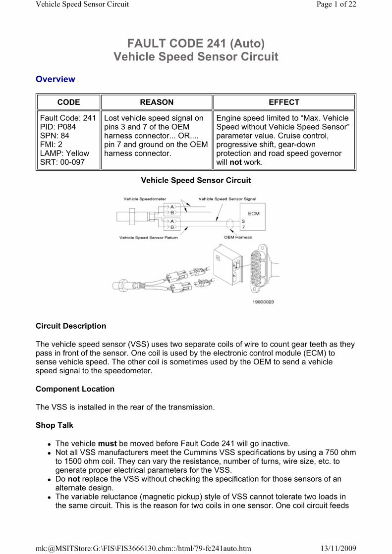
Circuit Description
The vehicle speed sensor (VSS) uses two separate coils of wire to count gear teeth as they pass in front of the sensor. One coil is used by the electronic control module (ECM) to sense vehicle speed. The other coil is sometimes used by the OEM to send a vehicle speed signal to the speedometer.
Component Location
The VSS is installed in the rear of the transmission.
Shop Talk
� The vehicle must be moved before Fault Code 241 will go inactive. � Not all VSS manufacturers meet the Cummins VSS specifications by using a 750 ohm to 1500 ohm coil. They can vary the resistance, number of turns, wire size, etc. to generate proper electrical parameters for the VSS.
� Do not replace the VSS without checking the specification for those sensors of an alternate design.
� The variable reluctance (magnetic pickup) style of VSS cannot tolerate two loads in the same circuit. This is the reason for two coils in one sensor. One coil circuit feeds
FAULT CODE 241 (Auto) Vehicle Speed Sensor Circuit
CODE REASON EFFECT
Fault Code: 241 PID: P084 SPN: 84 FMI: 2 LAMP: Yellow SRT: 00-097
Lost vehicle speed signal on pins 3 and 7 of the OEM harness connector... OR.... pin 7 and ground on the OEM harness connector.
Engine speed limited to “Max. Vehicle Speed without Vehicle Speed Sensor” parameter value. Cruise control, progressive shift, gear-down protection and road speed governor will not work.
Vehicle Speed Sensor Circuit
Page 1 of 22Vehicle Speed Sensor Circuit
13/11/2009mk:@MSITStore:G:\FIS\FIS3666130.chm::/html/79-fc241auto.htm
the ECM and the other feeds the speedometer. Any additional loads on a single coil will cause a Fault Code 241. Check for additional loads.
� A single coil VSS used in some applications, eg. automatic transmissions, will feed a conditioning circuit that outputs a digital speed signal to ECM pin 7.
� Note: ECM pin 3 is not used in this type of circuit and can be vacated. � Again, no additional loads can be spliced into the VSS between the sensor and conditioning circuit or vehicle interface module (VIM).
� The digital signal from the vehicle interface module conditioning circuit can feed multiple devices, like the ECM and the speedometer, simultaneously, since it has been properly conditioned for this purpose.
� Verify the VSS wires in the OEM harness are twisted pairs. � Fault Code 241 becomes active only if the ECM receives a speed signal and then loses the signal. The fault will not go active if it never received one, eg. the VSS is unplugged. The fault will go inactive once it picks up a speed signal again.
� Electrical noise or drivetrain vibration can simulate a VSS signal sitting still and, therefore, when the vibration or electrical noise dissipates, the fault can go active, i.e., the ECM had a valid signal and lost it.
Cautions and Warnings
Troubleshooting Steps
CAUTION
To avoid pin and harness damage, use the following test leads when taking a measurement: Part Number 3822758 - male Deutsch/AMP/Metri-Pack test lead Part Number 3823996 - female Weather-Pack test lead.
CAUTION
To avoid damaging a new ECM, all other active fault codes must be investigated prior to replacing the ECM.
CAUTION
To avoid pin and harness damage, use the following test lead when taking a measurement: Part Number 3823996 - female Weather-Pack test lead.
CAUTION
To avoid pin and harness damage, use the following test lead when taking a measurement: Part Number 3822758 - male Deutsch/AMP/Metri-Pack test lead.
Page 2 of 22Vehicle Speed Sensor Circuit
13/11/2009mk:@MSITStore:G:\FIS\FIS3666130.chm::/html/79-fc241auto.htm
STEPS SPECIFICATIONS
STEP 1. Check the VSS.
STEP 1A. Inspect the harness and the sensor connector pins.
No damaged pins
STEP 1B. Read the fault codes. Fault Code 241 is active
STEP 1C. Check the VSS for proper adjustment.
1/2 to 3/4 turn out from gear
STEP 1D. Inspect the harness and the ECM connector pins.
No damaged pins
STEP 1E. Read the fault codes. Fault Code 241 is active
STEP 1F. Check the VSS for the correct resistance.
750 to 1500 ohms or meets OEM specification
STEP 1G. Check the VSS for a short circuit to ground.
More than 100k ohms
STEP 1H. Check the VSS for a short circuit between coils.
More than 100k ohms
STEP 2. Check the OEM harness.
STEP 2A. Check the harness for a short circuit to ground.
More than 100k ohms
STEP 2B. Check the harness for a short circuit from pin-to-pin.
More than 100k ohms
STEP 3. Check the OEM components.
STEP 3A. Check for an external recording device.
No external device
STEP 3B. Check for a gear slipping on the shaft.
Gear attached properly
STEP 4. Check for electrical interference.
STEP 4A. Check vehicle speed sitting still.
No vehicle speed
STEP 4B. Check vehicle grounding.
Meets OEM specifications
STEP 4C. Check ground fuse. No ground wire at ECM case or fuse not blown
STEP 4D. Check vehicle speed w/ECM away from block.
No vehicle speed
STEP 4E. Check alternator. No vehicle speed
STEP 4F. Check other OEM components for shorting to
No vehicle speed
Page 3 of 22Vehicle Speed Sensor Circuit
13/11/2009mk:@MSITStore:G:\FIS\FIS3666130.chm::/html/79-fc241auto.htm
Guided Step 1 - Check the VSS.
Guided Step 1A - Inspect the harness and the sensor connector pins.
ground.
STEP 4G. Check engine brake circuit.
No vehicle speed
STEP 4H. Check datalink wiring for short circuit to ground.
More than 100k ohms
STEP 4I. Check injector circuits for short circuit to ground and fuel shutoff circuit.
More than 100k ohms
STEP 4J. Check EMI noise or feedback from another device on VSS circuit.
No vehicle speed
STEP 4K. Check for vehicle speed with VSS disconnected.
No vehicle speed
STEP 5. Clear the fault code.
STEP 5A. Disable the fault code. Fault Code 241 inactive
STEP 5B. Clear the inactive fault codes.
All faults cleared
Conditions
� Turn keyswitch "OFF". � Disconnect the OEM harness from the VSS.
� Flush and clean the connector pins using electronic contact cleaner, Part Number 3824510.
Action
Inspect the harness and the sensor connector pins for:
� bent or broken pins � pushed back or expanded pins � corroded pins � moisture in or on the connector
Page 4 of 22Vehicle Speed Sensor Circuit
13/11/2009mk:@MSITStore:G:\FIS\FIS3666130.chm::/html/79-fc241auto.htm
Guided Step 1B - Read the fault codes.
� missing or damaged seals � dirt or debris in or on the connector pins.
OK NOT OK
No damaged pins Repair the damaged pins. Repair or replace the OEM harness or the sensor, whichever has the damaged pins.
� Flush the dirt, debris, or moisture from the connector pins using electronic contact cleaner, Part Number 3824510.
� Repair the OEM harness. Refer to Procedure 019-201, 019-202, and 019-205 in the Troubleshooting and Repair Manual, Industrial CELECT™ Plus System, Bulletin 3666130.
� Replace the OEM harness. Refer to the OEM Troubleshooting and Repair Manual.
� Replace the VSS. Refer to Procedure 019-090 or 019-091 in the Troubleshooting and Repair Manual, Industrial CELECT™ Plus System, Bulletin 3666130.
Go to 1B Go to 5A
Conditions
� Turn keyswitch “OFF”. � Connect all components.
Action
Read the fault codes.
� Start the engine and move the vehicle.
� Read the fault codes using Compulink™, Part Number 3823549, Echek™, Part Number 3824437 or INSITE™, Part Number 3824638.
Page 5 of 22Vehicle Speed Sensor Circuit
13/11/2009mk:@MSITStore:G:\FIS\FIS3666130.chm::/html/79-fc241auto.htm
Guided Step 1C - Check the VSS for the proper adjustment.
Guided Step 1D - Inspect the harness and the ECM connector pins.
OK NOT OK
Fault Code 241 is active Repair complete.
Go to 1C Go to 5A
Conditions
� Turn keyswitch "OFF". � Disconnect the OEM harness from the VSS.
Action
Inspect the VSS.
� Check the VSS for proper adjustment.
� Note: This can vary for a VSS that is designed to have a different resistance value than shown in this tree and on the wiring diagram. Check with the OEM.
OK NOT OK
1/2 to 3/4 of a turn out from the gear Adjust the VSS. Refer to Procedure 019-090 or 019-091 in the Troubleshooting and Repair Manual, Industrial CELECT™ Plus System, Bulletin 3666130.
Go to 1D Go to 5A
CAUTION
To avoid damaging a new ECM, all other active fault codes must be investigated prior to replacing the ECM.
Conditions
Page 6 of 22Vehicle Speed Sensor Circuit
13/11/2009mk:@MSITStore:G:\FIS\FIS3666130.chm::/html/79-fc241auto.htm
� Turn keyswitch "OFF". � Disconnect the OEM harness connector from the ECM.
� Flush and clean the connector pins using electronic contact cleaner, Part Number 3824510.
Action
Inspect the harness and the ECM connector pins for:
� bent or broken pins � pushed back or expanded pins � corroded pins � moisture in or on the connector � missing or damaged seals � dirt or debris in or on the connector pins.
OK NOT OK
No damaged pins Repair the damaged pins. Repair or replace the OEM harness or ECM, whichever has the damaged pins.
� Flush the dirt, debris, or moisture from the connector pins using electronic contact cleaner, Part Number 3824510. Refer to Procedure 019-203 in the Troubleshooting and Repair Manual, Industrial CELECT™ Plus System, Bulletin 3666130.
� Repair the OEM harness. Refer to Procedure 019-203 in the Troubleshooting and Repair Manual, Industrial CELECT™ Plus System, Bulletin 3666130.
� Replace the OEM harness. Refer to the OEM Troubleshooting and Repair Manual.
� Replace the ECM. Refer to Procedure 019-031 in the Troubleshooting and Repair Manual, Industrial CELECT™ Plus System, Bulletin 3666130.
� Replace the o-ring on the 28-pin connector if it is damaged or missing. Refer to Procedure 019-203 in the Troubleshooting and Repair Manual, Industrial CELECT™ Plus System, Bulletin 3666130.
Page 7 of 22Vehicle Speed Sensor Circuit
13/11/2009mk:@MSITStore:G:\FIS\FIS3666130.chm::/html/79-fc241auto.htm
Guided Step 1E - Read the fault codes.
Guided Step 1F - Check the VSS for the correct resistance.
Go to 1E Go to 5A
Conditions
� Turn keyswitch “OFF”. � Connect all components.
Action
Read the fault codes.
� Start the engine and move the vehicle.
� Read the fault codes using Compulink™, Part Number 3823549, Echek™, Part Number 3824437, or INSITE™, Part Number 3824638.
OK NOT OK
Fault Code 241 is active Repair complete.
Go to 1F Go to 5A
CAUTION
To avoid pin and harness damage, use the following test lead when taking a measurement: Part Number 3823996 - female Weather-Pack test lead.
Conditions
� Turn keyswitch "OFF". � Disconnect the OEM harness from the VSS.
Action
Page 8 of 22Vehicle Speed Sensor Circuit
13/11/2009mk:@MSITStore:G:\FIS\FIS3666130.chm::/html/79-fc241auto.htm
Guided Step 1G - Check the VSS for a short circuit to ground.
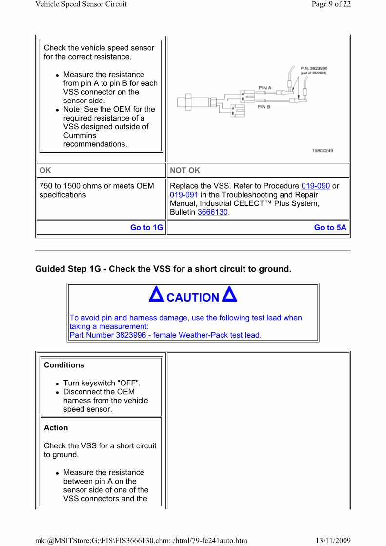
Check the vehicle speed sensor for the correct resistance.
� Measure the resistance from pin A to pin B for each VSS connector on the sensor side.
� Note: See the OEM for the required resistance of a VSS designed outside of Cummins recommendations.
OK NOT OK
750 to 1500 ohms or meets OEM specifications
Replace the VSS. Refer to Procedure 019-090 or 019-091 in the Troubleshooting and Repair Manual, Industrial CELECT™ Plus System, Bulletin 3666130.
Go to 1G Go to 5A
CAUTION
To avoid pin and harness damage, use the following test lead when taking a measurement: Part Number 3823996 - female Weather-Pack test lead.
Conditions
� Turn keyswitch "OFF". � Disconnect the OEM harness from the vehicle speed sensor.
Action
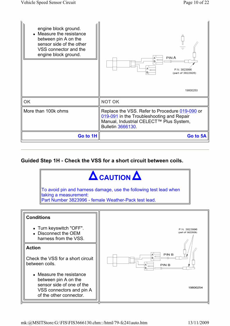
Check the VSS for a short circuit to ground.
� Measure the resistance between pin A on the sensor side of one of the VSS connectors and the
Page 9 of 22Vehicle Speed Sensor Circuit
13/11/2009mk:@MSITStore:G:\FIS\FIS3666130.chm::/html/79-fc241auto.htm
Guided Step 1H - Check the VSS for a short circuit between coils.
engine block ground. � Measure the resistance between pin A on the sensor side of the other VSS connector and the engine block ground.
OK NOT OK
More than 100k ohms Replace the VSS. Refer to Procedure 019-090 or 019-091 in the Troubleshooting and Repair Manual, Industrial CELECT™ Plus System, Bulletin 3666130.
Go to 1H Go to 5A
CAUTION
To avoid pin and harness damage, use the following test lead when taking a measurement: Part Number 3823996 - female Weather-Pack test lead.
Conditions
� Turn keyswitch "OFF". � Disconnect the OEM harness from the VSS.
Action
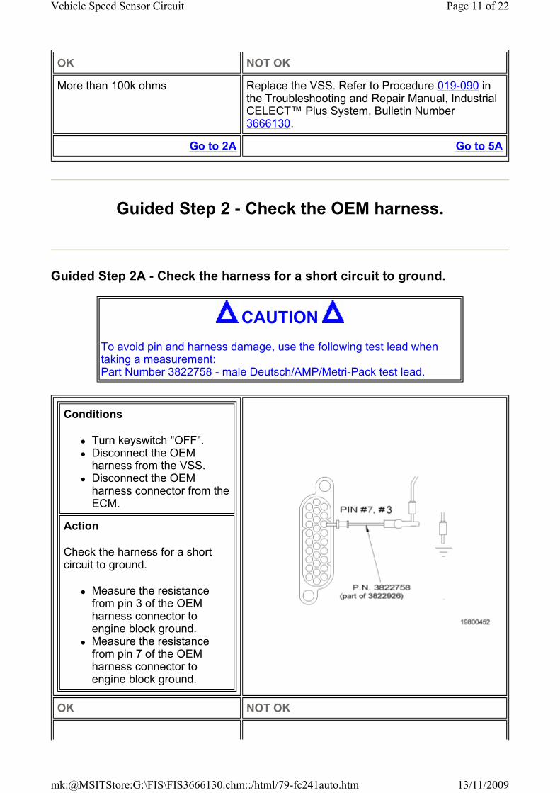
Check the VSS for a short circuit between coils.
� Measure the resistance between pin A on the sensor side of one of the VSS connectors and pin A of the other connector.
Page 10 of 22Vehicle Speed Sensor Circuit
13/11/2009mk:@MSITStore:G:\FIS\FIS3666130.chm::/html/79-fc241auto.htm
Guided Step 2 - Check the OEM harness.
Guided Step 2A - Check the harness for a short circuit to ground.
OK NOT OK
More than 100k ohms Replace the VSS. Refer to Procedure 019-090 in the Troubleshooting and Repair Manual, Industrial CELECT™ Plus System, Bulletin Number 3666130.
Go to 2A Go to 5A
CAUTION
To avoid pin and harness damage, use the following test lead when taking a measurement: Part Number 3822758 - male Deutsch/AMP/Metri-Pack test lead.
Conditions
� Turn keyswitch "OFF". � Disconnect the OEM harness from the VSS.
� Disconnect the OEM harness connector from the ECM.
Action
Check the harness for a short circuit to ground.
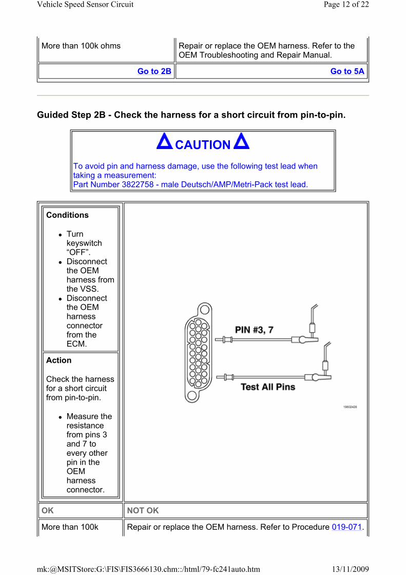
� Measure the resistance from pin 3 of the OEM harness connector to engine block ground.
� Measure the resistance from pin 7 of the OEM harness connector to engine block ground.
OK NOT OK
Page 11 of 22Vehicle Speed Sensor Circuit
13/11/2009mk:@MSITStore:G:\FIS\FIS3666130.chm::/html/79-fc241auto.htm
Guided Step 2B - Check the harness for a short circuit from pin-to-pin.
More than 100k ohms Repair or replace the OEM harness. Refer to the OEM Troubleshooting and Repair Manual.
Go to 2B Go to 5A
CAUTION
To avoid pin and harness damage, use the following test lead when taking a measurement: Part Number 3822758 - male Deutsch/AMP/Metri-Pack test lead.
Conditions
� Turn keyswitch “OFF”.
� Disconnect the OEM harness from the VSS.
� Disconnect the OEM harness connector from the ECM.
Action
Check the harness for a short circuit from pin-to-pin.
� Measure the resistance from pins 3 and 7 to every other pin in the OEM harness connector.
OK NOT OK
More than 100k Repair or replace the OEM harness. Refer to Procedure 019-071.
Page 12 of 22Vehicle Speed Sensor Circuit
13/11/2009mk:@MSITStore:G:\FIS\FIS3666130.chm::/html/79-fc241auto.htm
Guided Step 3 - Check the OEM components.
Guided Step 3A - Check for an external recording device.
Guided Step 3B - Check for a gear slipping on its shaft.
ohms
Go to 3A Go to 5A
Conditions
Turn keyswitch “OFF”.
Action
Check for an external device or similar devices attached to the VSS circuit between the sensor and ECM wired to pin 3 or pin 7.
� Note: Some applications, i.e., automatic transmissions, condition the signal and supply the conditioned signal to pin 7 as a digital vehicle speed signal. This type of signal can not feed pin 3. No splices can exist between the VSS and conditioning circuit (VIM) to include another device.
� Note: The variable reluctance (magnetic pickup) VSS does not source enough power to allow more than one device to exist between the ECM or conditioning circuit (VIM) and the vehicle speed sensor.
OK NOT OK
No external device Disconnect device from circuit
Go to 3B Go to 5A
Page 13 of 22Vehicle Speed Sensor Circuit
13/11/2009mk:@MSITStore:G:\FIS\FIS3666130.chm::/html/79-fc241auto.htm
Guided Step 4 - Check for electrical interference.
Guided Step 4A - Check vehicle speed.
Conditions
� Turn keyswitch "OFF". � VSS removed.
Action
Check for the gear slipping on the shaft.
� Check to make sure the transmission gear inside the sensor mounting is not slipping on the shaft. Do this by trying to spin the gear with a standard screwdriver.
OK NOT OK
Gear attached properly Repair transmission gear. Refer to the OEM Troubleshooting and Repair Manual.
Go to 4A Go to 5A
Conditions
� Connect all components.
Action
Verify vehicle speed.
� Check the vehicle speed with these conditions:
� Turn keyswitch “ON”, vehicle not running.
� Cranking engine with starter. � Vehicle parked, engine idling, with electronic service tool.
OK NOT OK
Page 14 of 22Vehicle Speed Sensor Circuit
13/11/2009mk:@MSITStore:G:\FIS\FIS3666130.chm::/html/79-fc241auto.htm
Guided Step 4B - Check for good vehicle grounding.
Guided Step 4C - Check for ground fuse.
No vehicle speed; vehicle parked Vehicle speed registers; vehicle parked.
Go to 5A Go to 4B
Conditions
� Turn keyswitch “OFF”.
Action
Check for good ground wires and connections.
� Check from negative (-) battery post to engine block ground.
� Check from block ground to negative (-) starter post ground.
� Check block to frame ground . � Check block to cab ground. � Frame to (-) battery ground. � Cab to (-) battery ground.
OK NOT OK
Ground connections are clean and tight. Measure within OEM specifications for voltage drop under electrical load
Correct vehicle grounds.
Go to 4C Go to 5A
Conditions
� Turn keyswitch “OFF”.
Action
If engine harness is equipped with a ground wire and fuseholder attached to the ECM case:
� Check the fuse.
Page 15 of 22Vehicle Speed Sensor Circuit
13/11/2009mk:@MSITStore:G:\FIS\FIS3666130.chm::/html/79-fc241auto.htm
Guided Step 4D - Check for vehicle speed sitting still with service tool.
Guided Step 4E - Check the alternator.
OK NOT OK
No ground wire at ECM case or fuse not blown
Fuse blown. Correct poor battery grounding or battery short to ground that caused fuse to blow. Replace fuse.
Go to 4D Go to 5A
Conditions
� Turn keyswitch “OFF”. � Connect all electrical components.
Action
Monitor for electrical or mechanical noise on engine block.
Monitor vehicle speed with these conditions:
� Turn keyswitch “ON”, engine not running.
� Cranking engine with starter motor. � Engine idling, vehicle parked, with electronic service tool.
OK NOT OK
No vehicle speed on electronic service tool Vehicle speed on electronic service tool.
Go to 5A Go to 4E
Conditions
� Remove the alternator belt. � Connect the ECM to the cooling plate.
� Connect the engine harness connector to the ECM.
Action
Page 16 of 22Vehicle Speed Sensor Circuit
13/11/2009mk:@MSITStore:G:\FIS\FIS3666130.chm::/html/79-fc241auto.htm
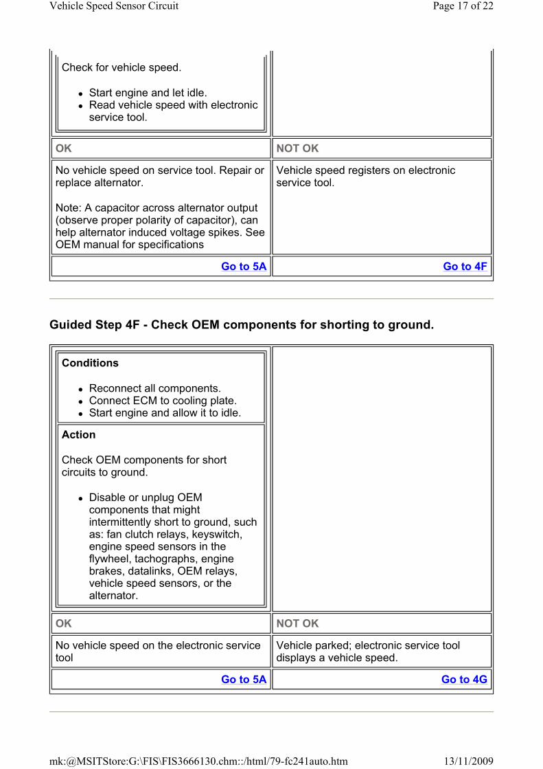
Guided Step 4F - Check OEM components for shorting to ground.
Check for vehicle speed.
� Start engine and let idle. � Read vehicle speed with electronic service tool.
OK NOT OK
No vehicle speed on service tool. Repair or replace alternator.
Note: A capacitor across alternator output (observe proper polarity of capacitor), can help alternator induced voltage spikes. See OEM manual for specifications
Vehicle speed registers on electronic service tool.
Go to 5A Go to 4F
Conditions
� Reconnect all components. � Connect ECM to cooling plate. � Start engine and allow it to idle.
Action
Check OEM components for short circuits to ground.
� Disable or unplug OEM components that might intermittently short to ground, such as: fan clutch relays, keyswitch, engine speed sensors in the flywheel, tachographs, engine brakes, datalinks, OEM relays, vehicle speed sensors, or the alternator.
OK NOT OK
No vehicle speed on the electronic service tool
Vehicle parked; electronic service tool displays a vehicle speed.
Go to 5A Go to 4G
Page 17 of 22Vehicle Speed Sensor Circuit
13/11/2009mk:@MSITStore:G:\FIS\FIS3666130.chm::/html/79-fc241auto.htm
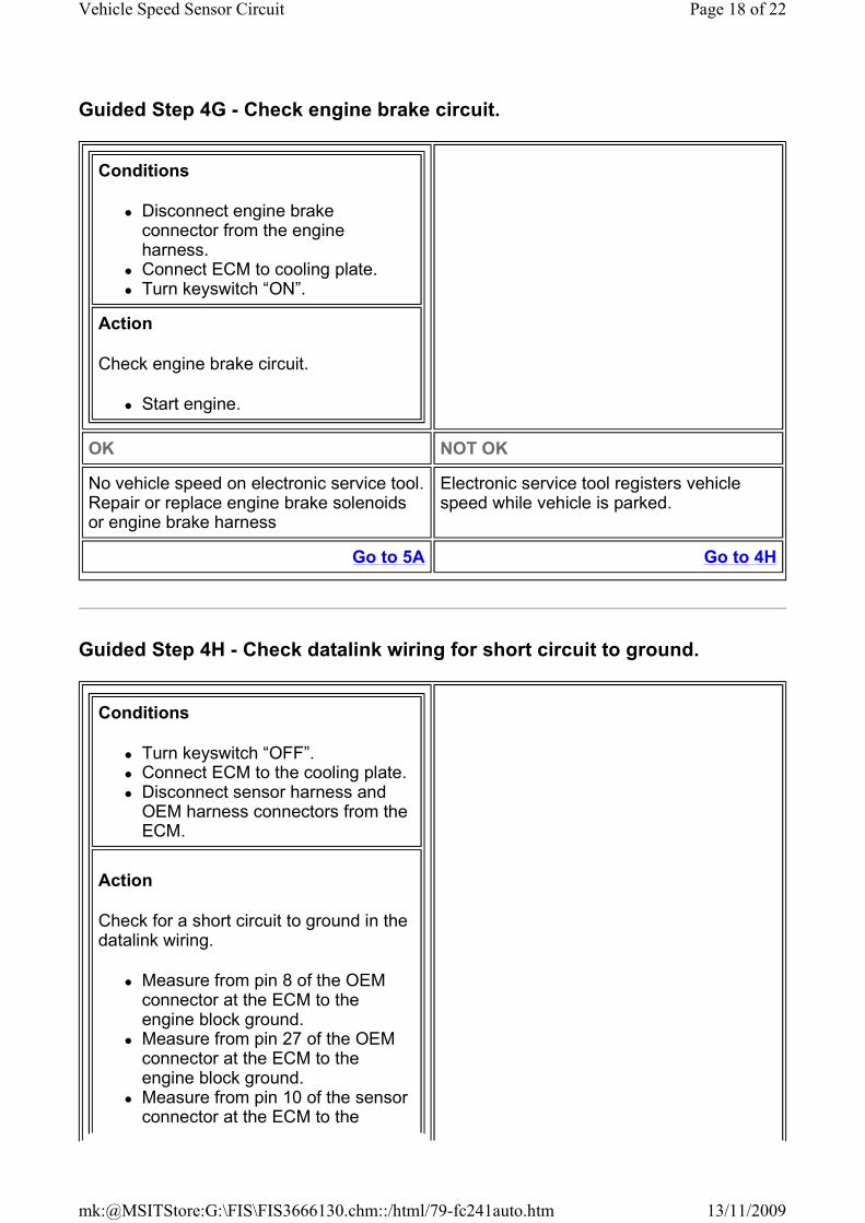
Guided Step 4G - Check engine brake circuit.
Guided Step 4H - Check datalink wiring for short circuit to ground.
Conditions
� Disconnect engine brake connector from the engine harness.
� Connect ECM to cooling plate. � Turn keyswitch “ON”.
Action
Check engine brake circuit.
� Start engine.
OK NOT OK
No vehicle speed on electronic service tool. Repair or replace engine brake solenoids or engine brake harness
Electronic service tool registers vehicle speed while vehicle is parked.
Go to 5A Go to 4H
Conditions
� Turn keyswitch “OFF”. � Connect ECM to the cooling plate. � Disconnect sensor harness and OEM harness connectors from the ECM.
Action
Check for a short circuit to ground in the datalink wiring.
� Measure from pin 8 of the OEM connector at the ECM to the engine block ground.
� Measure from pin 27 of the OEM connector at the ECM to the engine block ground.
� Measure from pin 10 of the sensor connector at the ECM to the
Page 18 of 22Vehicle Speed Sensor Circuit
13/11/2009mk:@MSITStore:G:\FIS\FIS3666130.chm::/html/79-fc241auto.htm
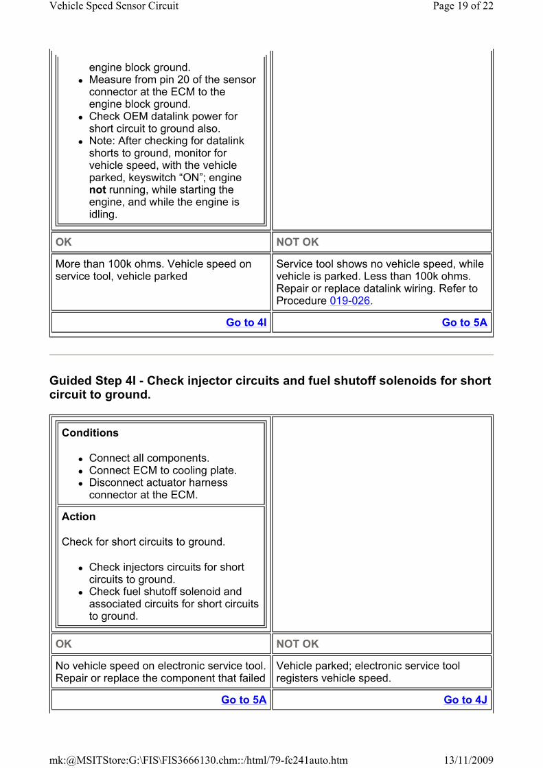
Guided Step 4I - Check injector circuits and fuel shutoff solenoids for short circuit to ground.
engine block ground. � Measure from pin 20 of the sensor connector at the ECM to the engine block ground.
� Check OEM datalink power for short circuit to ground also.
� Note: After checking for datalink shorts to ground, monitor for vehicle speed, with the vehicle parked, keyswitch “ON”; engine not running, while starting the engine, and while the engine is idling.
OK NOT OK
More than 100k ohms. Vehicle speed on service tool, vehicle parked
Service tool shows no vehicle speed, while vehicle is parked. Less than 100k ohms. Repair or replace datalink wiring. Refer to Procedure 019-026.
Go to 4I Go to 5A
Conditions
� Connect all components. � Connect ECM to cooling plate. � Disconnect actuator harness connector at the ECM.
Action
Check for short circuits to ground.
� Check injectors circuits for short circuits to ground.
� Check fuel shutoff solenoid and associated circuits for short circuits to ground.
OK NOT OK
No vehicle speed on electronic service tool. Repair or replace the component that failed
Vehicle parked; electronic service tool registers vehicle speed.
Go to 5A Go to 4J
Page 19 of 22Vehicle Speed Sensor Circuit
13/11/2009mk:@MSITStore:G:\FIS\FIS3666130.chm::/html/79-fc241auto.htm
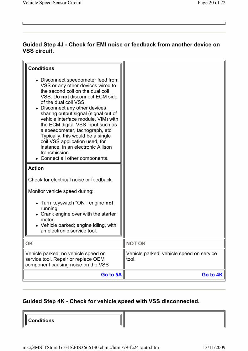
Guided Step 4J - Check for EMI noise or feedback from another device on VSS circuit.
Guided Step 4K - Check for vehicle speed with VSS disconnected.
Conditions
� Disconnect speedometer feed from VSS or any other devices wired to the second coil on the dual coil VSS. Do not disconnect ECM side of the dual coil VSS.
� Disconnect any other devices sharing output signal (signal out of vehicle interface module, VIM) with the ECM digital VSS input such as a speedometer, tachograph, etc. Typically, this would be a single coil VSS application used, for instance, in an electronic Allison transmission.
� Connect all other components.
Action
Check for electrical noise or feedback.
Monitor vehicle speed during:
� Turn keyswitch “ON”, engine not running.
� Crank engine over with the starter motor.
� Vehicle parked; engine idling, with an electronic service tool.
OK NOT OK
Vehicle parked; no vehicle speed on service tool. Repair or replace OEM component causing noise on the VSS
Vehicle parked; vehicle speed on service tool.
Go to 5A Go to 4K
Conditions
Page 20 of 22Vehicle Speed Sensor Circuit
13/11/2009mk:@MSITStore:G:\FIS\FIS3666130.chm::/html/79-fc241auto.htm
Guided Step 5 - Clear the fault code.
Guided Step 5A - Disable the fault code.
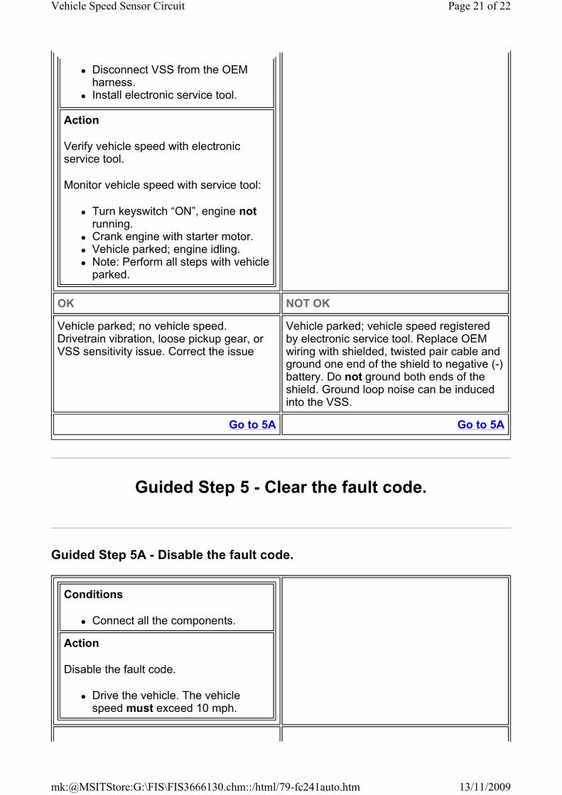
� Disconnect VSS from the OEM harness.
� Install electronic service tool.
Action
Verify vehicle speed with electronic service tool.
Monitor vehicle speed with service tool:
� Turn keyswitch “ON”, engine not running.
� Crank engine with starter motor. � Vehicle parked; engine idling. � Note: Perform all steps with vehicle parked.
OK NOT OK
Vehicle parked; no vehicle speed. Drivetrain vibration, loose pickup gear, or VSS sensitivity issue. Correct the issue
Vehicle parked; vehicle speed registered by electronic service tool. Replace OEM wiring with shielded, twisted pair cable and ground one end of the shield to negative (-) battery. Do not ground both ends of the shield. Ground loop noise can be induced into the VSS.
Go to 5A Go to 5A
Conditions
� Connect all the components.
Action
Disable the fault code.
� Drive the vehicle. The vehicle speed must exceed 10 mph.
Page 21 of 22Vehicle Speed Sensor Circuit
13/11/2009mk:@MSITStore:G:\FIS\FIS3666130.chm::/html/79-fc241auto.htm
Guided Step 5B - Clear the inactive fault codes.
Last Modified: 03-May-2005
Copyright© 2005
Cummins, Inc. All rights reserved
OK NOT OK
Fault Code 241 is inactive Return to the troubleshooting steps or contact your local Cummins Authorized Repair Location if all the steps have been completed and checked again.
Go to 5B Go to 1A
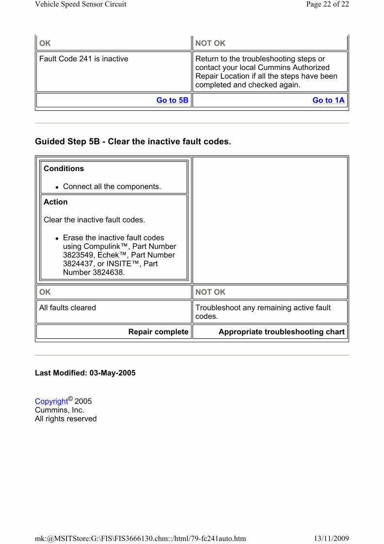
Conditions
� Connect all the components.
Action
Clear the inactive fault codes.
� Erase the inactive fault codes using Compulink™, Part Number 3823549, Echek™, Part Number 3824437, or INSITE™, Part Number 3824638.
OK NOT OK
All faults cleared Troubleshoot any remaining active fault codes.
Repair complete Appropriate troubleshooting chart
Page 22 of 22Vehicle Speed Sensor Circuit
13/11/2009mk:@MSITStore:G:\FIS\FIS3666130.chm::/html/79-fc241auto.htm