Embed Size (px)
Citation preview
8/7/2019 Fault Finding Chart for Motorcycle Electrical Systems
http://slidepdf.com/reader/full/fault-finding-chart-for-motorcycle-electrical-systems 1/4
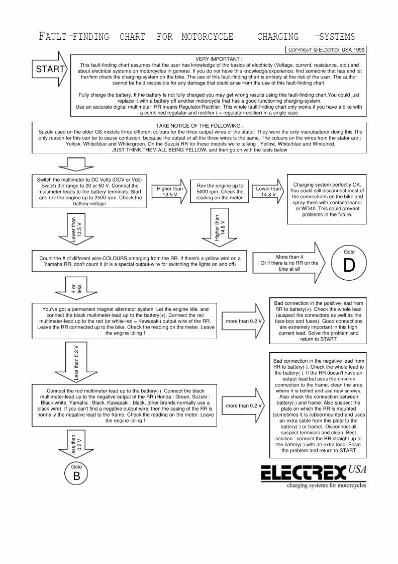
START
Count the # of different wire-COLOURS emerging from the RR. If there's a yellow wire on aYamaha RR, don't count it (it is a special output-wire for switching the lights on and off)
More than 4Or if there is no RR on the
bike at all
4 o r
l e s s
You've got a permanent magnet alternator system. Let the engine idle, andconnect the black multimeter-lead up to the battery(+). Connect the red
multimeter-lead up to the red (or white-red = Kawasaki) output wire of the RR.Leave the RR connected up to the bike. Check the reading on the meter. Leave
the engine idling !
VERY IMPORTANT :This fault-finding chart assumes that the user has knowledge of the basics of electricity (Voltage, current, resistance, etc.),and
about electrical systems on motorcycles in general. If you do not have this knowledge/experience, find someone that has and lether/him check the charging-system on the bike. The use of this fault-finding chart is entirely at the risk of the user. The author
cannot be held resposible for any damage that could arise from the use of this fault-finding chart.
Fully charge the battery. If the battery is not fully charged you may get wrong results using this fault-finding chart.You could just
replace it with a battery off another motorcycle that has a good functioning charging-system.Use an accurate digital multimeter! RR means Regulator/Rectifier. This whole fault-finding chart only works if you have a bike with
a combined regulator and rectifier ( = regulator/rectifier) in a single case
Switch the multimeter to DC Volts (DCV or Vdc)Switch the range to 20 or 50 V. Connect the
multimeter-leads to the battery-terminals. Start
and rev the engine up to 2500 rpm. Check thebattery-voltage
Higher than13.5 V
L o w e r
t h a n
1 3
. 5 V
Rev the engine up to5000 rpm. Check the
reading on the meter.
H i g h e r
t h a n
1 4
. 8 V
Lower than14.8 V
Charging system perfectly OK.You could still disconnect most of
the connections on the bike andspray them with contactcleaneror WD40. This could prevent
problems in the future.
more than 0.2 V
Bad connection in the positive lead fromRR to battery(+). Check the whole lead(suspect the connectors as well as thefuse-box and fuses). Good connections
are extremely important in this highcurrent lead. Solve the problem and
return to START
L e s s
t h a n
0 . 2
V
Connect the red multimeter-lead up to the battery(-). Connect the black
multimeter-lead up to the negative output of the RR (Honda : Green, Suzuki :Black-white, Yamaha : Black, Kawasaki : black, other brands normally use a
black wire). If you can't find a negative output-wire, then the casing of the RR isnormally the negative lead to the frame. Check the reading on the meter. Leave
the engine idling !
more than 0.2 V
Bad connection in the negative lead fromRR to battery(-). Check the whole lead tothe battery(-). If the RR doesn't have an
output-lead but uses the case as
connection to the frame, clean the areawhere it is bolted and use new screws.
Also check the connection betweenbattery(-) and frame. Also suspect the
plate on which the RR is mounted(sometimes it is rubbermounted and uses
an extra cable from this plate to thebattery(-) or frame). Disconnect allsuspect terminals and clean. Best
solution : connect the RR straight up tothe battery(-) with an extra lead. Solve
the problem and return to START l e s s
t h a n
0 . 2
V
Goto
D
Goto
B
FAULT-FINDING CHART FOR MOTORCYCLE CHARGING -SYSTEMS
TAKE NOTICE OF THE FOLLOWING :Suzuki used on the older GS models three different colours for the three output-wires of the stator. They were the only manufacturer doing this.The
only reason for this can be to cause confusion, because the output of all the three wires is the same. The colours on the wires from the stator are :Yellow, White/blue and White/green. On the Suzuki RR for these models we're talking : Yellow, White/blue and White/red.
JUST THINK THEM ALL BEING YELLOW, and then go on with the tests below
COPYRIGHT © ELECTREX USA 1999
8/7/2019 Fault Finding Chart for Motorcycle Electrical Systems
http://slidepdf.com/reader/full/fault-finding-chart-for-motorcycle-electrical-systems 2/4
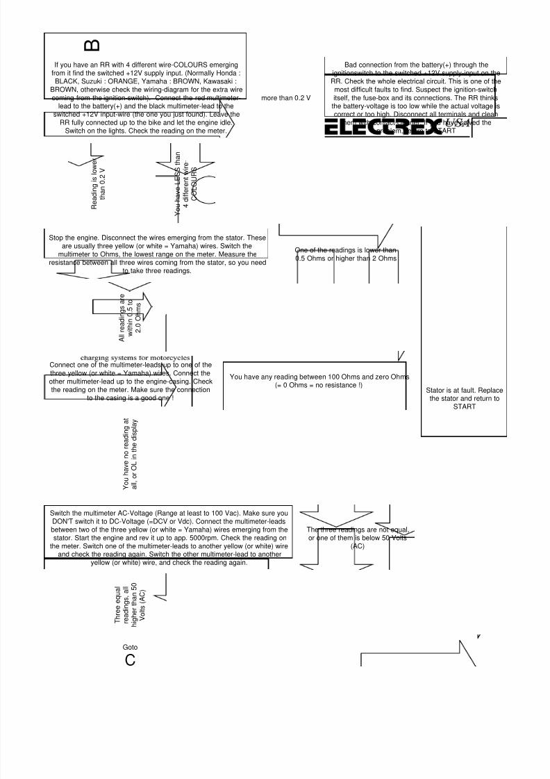
BIf you have an RR with 4 different wire-COLOURS emerging
from it find the switched +12V supply input. (Normally Honda :BLACK, Suzuki : ORANGE, Yamaha : BROWN, Kawasaki :
BROWN, otherwise check the wiring-diagram for the extra wire
coming from the ignition-switch). Connect the red multimeter-lead to the battery(+) and the black multimeter-lead to the
switched +12V input-wire (the one you just found). Leave theRR fully connected up to the bike and let the engine idle.
Switch on the lights. Check the reading on the meter.
more than 0.2 V
Bad connection from the battery(+) through theignitionswitch to the switched +12V supply-input on theRR. Check the whole electrical circuit. This is one of themost difficult faults to find. Suspect the ignition-switch
itself, the fuse-box and its connections. The RR thinksthe battery-voltage is too low while the actual voltage iscorrect or too high. Disconnect all terminals and clean
them with contact-cleaner. If you have solved theproblem, return to START
R e a
d i n g
i s l o w e r
t h a n
0 . 2
V
Stop the engine. Disconnect the wires emerging from the stator. Theseare usually three yellow (or white = Yamaha) wires. Switch the
multimeter to Ohms, the lowest range on the meter. Measure theresistance between all three wires coming from the stator, so you need
to take three readings.
One of the readings is lower than0.5 Ohms or higher than 2 Ohms
Stator is at fault. Replacethe stator and return to
START
A l l r e a
d i n g s a r e
w i t h i n 0
. 5 t o
2 . 0
O h m s
Connect one of the multimeter-leads up to one of the
three yellow (or white = Yamaha) wires. Connect theother multimeter-lead up to the engine-casing. Checkthe reading on the meter. Make sure the connection
to the casing is a good one !
You have any reading between 100 Ohms and zero Ohms(= 0 Ohms = no resistance !)
Y o u
h a v e n o r e a
d i n g a
t
a l l , o r
O L i n t h e
d i s p
l a y
Switch the multimeter AC-Voltage (Range at least to 100 Vac). Make sure youDON'T switch it to DC-Voltage (=DCV or Vdc). Connect the multimeter-leadsbetween two of the three yellow (or white = Yamaha) wires emerging from thestator. Start the engine and rev it up to app. 5000rpm. Check the reading on
the meter. Switch one of the multimeter-leads to another yellow (or white) wireand check the reading again. Switch the other multimeter-lead to another
yellow (or white) wire, and check the reading again.
The three readings are not equal,or one of them is below 50 Volts
(AC)
T h r e e e q u a
l
r e a
d i n g s ,
a l l
h i g h e r
t h a n
5 0
V o
l t s ( A C )
Goto
C
Y o u
h a v e
L E S S t h a n
4 d i f f e r e n
t w
i r e -
C O L O U R S
8/7/2019 Fault Finding Chart for Motorcycle Electrical Systems
http://slidepdf.com/reader/full/fault-finding-chart-for-motorcycle-electrical-systems 3/4
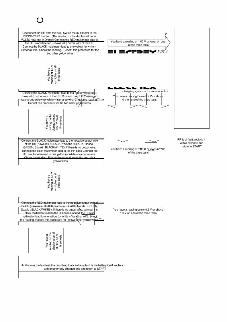
C
Disconnect the RR from the bike. Switch the multimeter to theDIODE-TEST function. (The reading on the display will be in
VOLTS now, not in Ohms!) Connect the RED multimeter-lead tothe RED (or white/red = Kawasaki) output wire of the RR.
Connect the BLACK multimeter-lead to one yellow (or white =Yamaha) wire. Check the reading. Repeat this procedure for the
two other yellow wires.
You have a reading of 1.00 V or lower on oneof the three tests.
RR is at fault, replace itwith a new one and
return to START
Y o u
h a v e a
r e a
d i n g o
f 1
. 5 V
o r
h i g h e r o n a
l l
t h r e e
t e s
t s
Connect the BLACK multimeter-lead to the red (or white/red =Kawasaki) output wire of the RR. Connect the RED multimeter-lead to one yellow (or white = Yamaha) wire. Check the reading.
Repeat this procedure for the two other yellow wires.
You have a reading below 0.2 V or above1.0 V on one of the three tests
Connect the BLACK multimeter-lead to the negative output wireof the RR (Kawasaki : BLACK, Yamaha : BLACK, Honda :
GREEN, Suzuki : BLACK/WHITE). If there is no output wire,connect the black multimeter-lead to the RR-case Connect theRED multimeter-lead to one yellow (or white = Yamaha) wire.Check the reading. Repeat this procedure for the two other
yellow wires.
Y o u
h a v e a
r e a
d i n g o n
t h e
d i s p
l a y a r o u n
d
0 . 5
0 V o n a
l l
t h r e e
t e s
t s
You have a reading of 1.00 V or lower on one
of the three tests.
Connect the RED multimeter-lead to the negative output wire of
the RR (Kawasaki: BLACK, Yamaha : BLACK, Honda : GREEN,Suzuki : BLACK/WHITE ). If there is no output wire, connect the
black multimeter-lead to the RR-case Connect the BLACKmultimeter-lead to one yellow (or white = Yamaha) wire. Check
the reading. Repeat this procedure for the two other yellow wires.
Y o u
h a v e a
r e a
d i n g o
f 1
. 5 V
o r
h i g h e r o n a
l l
t h r e e
t e s
t s
You have a reading below 0.2 V or above1.0 V on one of the three tests
Y o u
h a v e a
r e a
d i n g o n
t h e
d i s p
l a y a r o u n
d
0 . 5
0 V o n a
l l
t h r e e
t e s
t s
As this was the last test, the only thing that can be at fault is the battery itself. replace itwith another fully charged one and return to START

8/7/2019 Fault Finding Chart for Motorcycle Electrical Systems
http://slidepdf.com/reader/full/fault-finding-chart-for-motorcycle-electrical-systems 4/4
D
Is there an RR on the bike ? (somewhere on the frameunder the bodywork)
No
You have an integrated generator (car-type, with built in regulator andrectifier). Most of the problems with this kind of generator are bad
connections, from generator to battery (battery doesn't charge), or aburned out regulator (battery-voltage too high) Sometimes the
generator itself is at fault. You could check the resistance of thefieldwinding (around 5 Ohms) and the state the brushes are in.
Otherwise leave it to an expert. After solving the problem, return toSTART
Y e s
Stop the engine. Disconnect theblockconnector to the generator closestto the engine. This connector must haveat least three yellow (or white = Yamaha)
wires in it and one or two extra ones.Switch the multimeter to the lowest
Ohms-range. measure the resistancebetween the two other wires, or between
the single extra one (apart from theyellow ones) and the engine-casing.
You have a readinglower than 3 Ohms or
higher than 10 Ohms
The fieldwinding in thegenerator or the brushes to the
rotor are at fault. If there areany brushes inside the
generator, disconnect them andmeasure the resistance
between the two copper slip-rings on the rotor. These are
the rings on which the brushes
run.
(If there are no brushes insidethe generator, replace thefieldwinding or if that's not
possible separately, replace the
whole stator and return toSTART)
r e s
i s t a n c e
b e
t w e e n
4
O h m s a n
d 6
O h m s
Rotor at fault.Replace it with a
new one, and return
to START
resistancelower than 3
Ohms or
higher than 6Ohms
Wiring to the brushes or the brushes themselves at fault. Replace thebrushes, check the wiring to the brushes and return to START
R e a
d i n g
b e
t w e e n
4
O h m s a n
d 6 O h m s
Connect one spare wire to the battery(+) terminal and connect it up
to one of the extra wires that are in the blockconnector, apart fromthe yellow (or white = Yamaha) wires. Connect a second spare wirebetween the battery(-) and the other extra wire in the connectorblock.
If you have only one extra wire, only connect the battery(+) wire tothis one. Make sure the battery(-) is still connected to the frame.Switch the multimeter to AC-Volts, range at least 100 V (ACV or
Vac). Start the engine and rev it up to app. 5000 rpm. Connect themultimeter-leads up between two of the yellow (or white = Yamaha)wires. Check reading on multimeter. Switch one of the multimeter-
leads to another yellow wire and check the reading again. Thenswitch the other multimeter-lead and check the reading again.
The three readings arenot equal, or they arebelow 50 Volts (AC)
Stator at fault. Replace stator and return toSTART
T h r e e e q u a
l
r e a
d i n g s ,
a l l
h
i g h e r
t h a n
5 0
V o
l t s ( A C )
Stop the engine. Switch the multimeter to DC-Voltage (DCV or Vdc). With the block-connectordisconnected as above, connect the multimeter-leads up to the two extra wires in this connector (apart fromthe three yellow wires), this in the connector-block emerging from the wiring-loom, not the other side going
to the generator. If there's only one extra wire, connect it to one multimeter-lead and connect the othermultimeter-lead to the engine-casing. When you switch on the ignition, Check the reading on the display.
No reading or areading lower than
10 V (DC)
RR at fault.Replace itwith a new
one andreturn toSTART
Switch the multimeter to DC-Voltage (DCV or Vdc) Range 20or 50V. Connect the multimeter-leads to the battery-terminals.
Start the engine and rev it up to app.5000rpm. Check thevoltage-reading.
L o w e r
t h a n
1 4
. 8 V
Higher than 14.8 VRR at fault. Voltage is not regulated. Replace the RR
and return to START
R e a
d i n g
1 0 V o r
h i g h e r
Goto
C