Embed Size (px)
Citation preview
8/7/2019 Fault Tolerant Permenant Magnet Machine Drives
http://slidepdf.com/reader/full/fault-tolerant-permenant-magnet-machine-drives 1/21
FAULT TOLERANT PERMENANT MAGNET
MACHINE DRIVES
Document By
SANTOSH BHARADWAJ REDDY
Email: [email protected]
Engineeringpapers.blogspot.com
More Papers and Presentations available on above site
Abstract:
The project examines the use of permanent magnet machine drives in high
performance, safety-critical applications. Likely fault modes are identified
and machine designs are developed for fault-tolerant operation, without
severely compromising the drive performance. Fault tolerance is achieved
by adopting a modular approach to the drive, with each phase electrically,
magnetically, thermally and physically independent of all others. Power
converter requirements are discussed and methods for controlling a faulted
phase developed to minimize the impact of a machine or power converter
fault.
8/7/2019 Fault Tolerant Permenant Magnet Machine Drives
http://slidepdf.com/reader/full/fault-tolerant-permenant-magnet-machine-drives 2/21
List of symbols
Aerospace applications demand drives with both high reliability and large
power to mass ratios. Recent research in the USA [l-31 has led to the
development of switched reluctance drives for the aerospace market because
of their inherent fault tolerance, despite an arguably reduced power density
compared to other machine types. Research by the current authors [4] has
questioned the justification of abandoning high performance permanent
magnet drives. This paper describes experimental results from a permanent
magnet machine, which has been designed with fault tolerance in mind. The
main thrust of this contribution is concerned with demonstrating that the
fault-tolerant electromagnetic performance can be achieved. The machine
must be designed so that even with a winding or switching device short
8/7/2019 Fault Tolerant Permenant Magnet Machine Drives
http://slidepdf.com/reader/full/fault-tolerant-permenant-magnet-machine-drives 3/21
circuit the fault currents are limited to a level within steady state thermal
limits. Penalties must be considered in terms of machine volume and power
switching device rating, although it is shown that these penalties are not
severe.
There are many potential faults which can occur in a drive system:
inevitably within this work the range of faults under consideration must be
restricted. For example, a design which is insensitive to the failure of a
position transducer would probably require sensorles operation, which is
beyond the scope of this paper. The principal electromagnetic faults which
may occur within the machine are:
(i) winding open circuit
(ii) winding short circuit (phase-ground or within a
phase)
(iii) winding short circuit at the terminals.
eration are:
(i) power device open circuit
(ii) power device short circuit
(iii) DC link capacitor failureThe aim is to develop a drive which can continue to operate with any one of
these faults. It has become clear that the most successful design approach
involves a multiple phase drive in which each phase may be regarded as a
single module. The operation of any one module must have minimal impact
8/7/2019 Fault Tolerant Permenant Magnet Machine Drives
http://slidepdf.com/reader/full/fault-tolerant-permenant-magnet-machine-drives 4/21
upon the others, so that in the event of that module failing the others can
continue to operate unaffected. The above modular approach requires that
there should be minimal electrical, magnetic and thermal interac
between phases of the drive. This philosophy must extend to both the
machine and the power converter. The requirements are naturally met in a
switched reluctance motor [3]; separate half bridges are used for each phase
and so the phases are electrically decoupled, and there is low mutual
magnetic coupling between phases. Because the SRM is a singly excited
machine, fault current will not continue to be driven into a faulted phase,
once excitation of that phase is removed. Furthermore, there is reduced
likelihood of a phase-phase fault because the end windings do not overlap.
However, it must be noted that two phases do occupy the same slot, so that
thermal isolation between phases is limited.
A conventional permanent magnet machine has a significantly greater
specific output than a switched reluctance machine, but it has none of the
inherent fault-tolerant capabilities. The following Section will address how a
permanent magnet drive may be designed to enhance its fault tolerance.
The requirements outlined in the previous Section naturally fix certain
features of the machine design and drive configuration. These requirements
will be considered for a voltage fed inverter drive.
3.1 Complete electrical isolation between phases
8/7/2019 Fault Tolerant Permenant Magnet Machine Drives
http://slidepdf.com/reader/full/fault-tolerant-permenant-magnet-machine-drives 5/21
This can be shown to be an essential requirement if continued operation is to
occur with either a power device or winding short-circuited. For instance, in
a star connected system the star point may rise to the DC link voltage, so
that no net torque capability remains. The clear alternative is to drive each
phase from a separate single-phase bridge [SI. This doubles the number of
power devices but only marginally increases the total power electronic
device volt-ampere rating, because each device need only withstand the
phase voltage rather than the line voltage of star connected systems.
3.2 Implicit limiting of fault currents
The most difficult machine fault to accommodate is a winding short-circuit.
Section 7 shows that a power electronic device short-circuit failure produces
a similar condition to a winding terminal short circuit, except that the fault
current flows through the converter as well as the winding. Thus, a phase
terminal short-circuit has received particular attention. The system was
designed without any fuses incorporated into the drive, as the reliability of
fuses is generally poor. This leaves two possibilities for dealing with the
above fault conditions. (a) The machine can be deliberately designed with a
low per unit inductance, so that a large fault current flows. Thus, a winding
short-circuit fault will result in a very large winding short-circuit fault
current, the faulted winding will overheat and subsequently produce an
open-circuit. Equally a device short circuit will produce a very large faulted
device current, and the subsequent heating will eventually produce an open-
circuit condition. Alternatively, (b) the machine can be designed with a d
axis per unit inductance approaching 1.0 per unit, so that a phase terminal
short circuit will not result in steady state motor currents beyond 1.0 per
8/7/2019 Fault Tolerant Permenant Magnet Machine Drives
http://slidepdf.com/reader/full/fault-tolerant-permenant-magnet-machine-drives 6/21
unit. The thermal limit of the faulted winding will not be exceeded and the
short circuit can be accommodated over an extended period. Torque ripple
resulting from the short-circuit current in the faulted phase will inevitably be
large unless special measures are employed. The second of the above
approaches provides a more reliable, fault-tolerant solution, as the first
option allows very large per unit fault currents to flow in failed power
electronic devices until they turn open circuit. The faulted device will
experience large thermal stresses, which may lead to disintegration of the
packaging and propagation of the fault into surrounding power devices.
Producing an effective d axis inductance of one per unit is generally
considered difficult to achieve in a small permanent magnet machine, but it
is shown in a later section that this can in fact be achieved relatively easily.
3.3 Magnetic isolation between phases
Without magnetic isolation, fault currents in one phase induce large voltages
in other phases, preventing adequate control of them [4]. Furthermore, the
current flowing in unfaulted phases supplements the magnet MMF and so
increases the EMF driving fault current. Thus it becomes clear that for a
given unfaulted armature reaction field the single phase short-circuit fault
current is substantially greater when there is mutual coupling between
phases. A torque controller has been developed to minimize the machine
output torque ripple when operating in the faulted condition. The controller
identifies current profiles which produce a given torque demand
minimum i2R loss under both normal and faulted conditions, thus giving
closed loop torque control. This torque control was found to be severely
impaired by substantial phase-phase mutual coupling. The above results
8/7/2019 Fault Tolerant Permenant Magnet Machine Drives
http://slidepdf.com/reader/full/fault-tolerant-permenant-magnet-machine-drives 7/21
show that both the faulted and unfaulted phases perform substantially worse
when there is mutual coupling between phases, so the machine should be
designed with minimal phase-phase mutual coupling. In surface mounted
magnet designs the air gap flux due to armature reaction is small and a
substantial amount of the phase inductance arises due to cross-slot leakage
flux. If this is to remain solely a self inductance component then each slot
should contain the conductors of one phase only. The component of
armature reaction flux which crosses the air gap will always contain an
element which links the other phases. However, if a surface mounted magnet
design with a nonmagnetic retaining sleeve is employed, then the presence
of the sleeve, combined with relatively deep magnets, greatly reduces the air
gap component of the armature reaction field, so that in effect the mutual
coupling is insignificant.
3.4 Effective thermal isolation between
phasesIf the stator outer surface is well cooled then the dominant temperature rise
in the machine is within each slot. By ensuring that each slot contains only a
single phase winding then thermal interaction between phases is minimized.
3.5 Physical isolation between phases
A phase-phase fault is especially serious, since it will disable two phases. By
placing each winding round a single tooth then all phase windings (including
the end windings) are physically separated, thus virtually
eliminating the possibility of a phase to phase fault.
8/7/2019 Fault Tolerant Permenant Magnet Machine Drives
http://slidepdf.com/reader/full/fault-tolerant-permenant-magnet-machine-drives 8/21
3.6 Number of phasesThe basic criteria used is that the drive should continue to produce rated
power in the event of the failure of one phase. Hence, if there are n phases,
each phase must be overrated by a fault-tolerant rating factor, F, where F =
n/ (n - 1). Thus, if there are three phases, each drive must be overrated by
50% in order to give full capability when faulted. Clearly, F falls as the
number of phases rises, but this must be balanced against the increasing
complexity of a high phase number and the inevitably greater chance of a
failure.
3.7 Summary
With regard to the machine design, the essential conclusions are that the
machine should have (i) a surface mounted magnet rotor design, (ii) a one
per-unit armature self inductance, (iii) each winding wound around a single
tooth and (iv) only one phase winding per slot.
The first two conclusions appear to be in conflict because a surface mounted
magnet machine generally has a low per unit reactance. However, the key to
achieving these requirements is to design a machine with a large leakage
inductance by controlling the depth and width of the slot op
commonly called the stator reactance slot. In the event of a phase winding
short circuit then one half of the magnet flux which normally passes up one
tooth must be shunted across each reactance slot. To avoid undue saturation
the reactance slot depth is designed to be approximately one half of the tooth
8/7/2019 Fault Tolerant Permenant Magnet Machine Drives
http://slidepdf.com/reader/full/fault-tolerant-permenant-magnet-machine-drives 9/21
width, with the reactance slot width chosen according to the required
inductance.
4 Analysis of machine winding failures
In the above discussion a winding short circuit at the terminals is considered,
but no consideration is made of the more difficult case, where the short
occurs between two adjacent turns of a winding. The single turn short circuit
is a troublesome fault for all machine types and its detection is a topic of
ongoing research. In a switched reluctance machine it is necessary to detect
the fault quickly and subsequently remove excitation from the faulted phase.
In a permanent magnet machine it is equally important to have fast fault
detection, but once detected a different course of action is appropriate.
For simplicity of explanation consider a simple case where a winding of N
turns has a sinusoidally varying flux-linkage from the magnet of magnitude
Yf per unit, and a per unit self inductance, Lpu (assume no phase phase
mutual coupling in this case). The peak per unit current which flows in theevent of a terminal short circuit is given by
In all but small, slow speed machines the per unit resistive effect is almost
negligible, so that a terminal short circuit produces very little mean braking
torque, and the fault current is limited by the inductance. Clearly if Lpu is
equal to Yf then l.0pu current will flow.
Now consider the case where the short is across just one turn of the N turn
winding. The induced current in this turn is given by
8/7/2019 Fault Tolerant Permenant Magnet Machine Drives
http://slidepdf.com/reader/full/fault-tolerant-permenant-magnet-machine-drives 10/21
Thus if the inductive term remains greater than the resistive one the fault
current in the shorted turn will be N pu. In reality the resistive term is
generally now dominant, but the fault current remains very large and will
cause very high localized heating. This can be explained in general terms by
the realization that the MMF of the single faulted turn is trying to produce a
component of flux which cancels out the magnet flux linkage. It appears,
therefore, that while a terminal short circuit can be accommodated, a single
turn short circuit cannot. However, if the shorted turn can be detected
quickly then the situation can be returned to one analogous to a terminal
short circuit by shorting the terminals through the power converter. This
forces all the turns to share the winding MMF and reduces the current in the
single faulted turn back to rated value. Of course such action is dependant
upon fault detection and subsequent application of the terminal short circuit
in less time than the faulted turn reaches its thermal limit, which may be
considerably under one second.
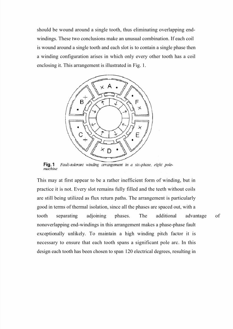
Section 3 indicates that there should be only one phase winding per slot to
maximize thermal isolation and minimize mutual coupling between phases.
However, to prevent phase-phase faults it was also concluded that each coil
8/7/2019 Fault Tolerant Permenant Magnet Machine Drives
http://slidepdf.com/reader/full/fault-tolerant-permenant-magnet-machine-drives 11/21
should be wound around a single tooth, thus eliminating overlapping end-
windings. These two conclusions make an unusual combination. If each coil
is wound around a single tooth and each slot is to contain a single phase then
a winding configuration arises in which only every other tooth has a coil
enclosing it. This arrangement is illustrated in Fig. 1.
This may at first appear to be a rather inefficient form of winding, but in
practice it is not. Every slot remains fully filled and the teeth without coils
are still being utilized as flux return paths. The arrangement is particularly
good in terms of thermal isolation, since all the phases are spaced out, with a
tooth separating adjoining phases. The additional advantage
nonoverlapping end-windings in this arrangement makes a phase-phase fault
exceptionally unlikely. To maintain a high winding pitch factor it is
necessary to ensure that each tooth spans a significant pole arc. In this
design each tooth has been chosen to span 120 electrical degrees, resulting in
8/7/2019 Fault Tolerant Permenant Magnet Machine Drives
http://slidepdf.com/reader/full/fault-tolerant-permenant-magnet-machine-drives 12/21
three teeth per pole pair. The winding pattern repeats every two pole pairs,
with 240 electrical degrees between adjacent phases.
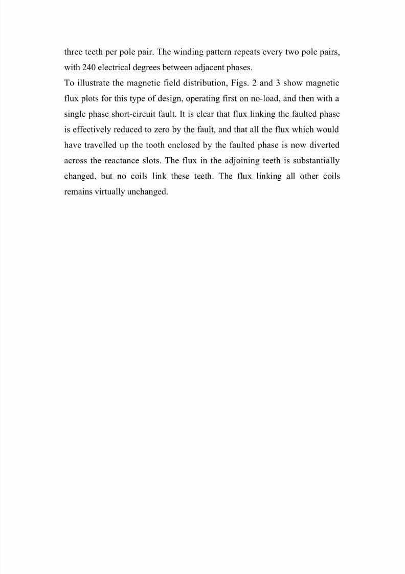
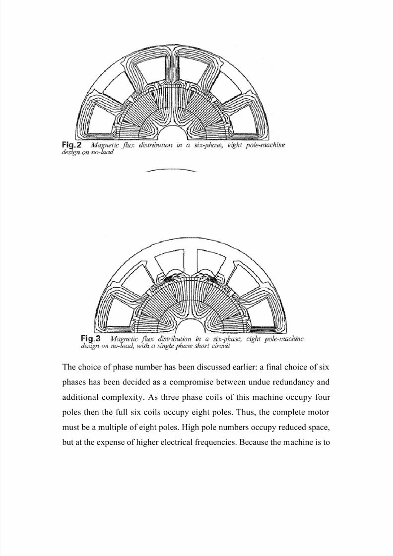
To illustrate the magnetic field distribution, Figs. 2 and 3 show magnetic
flux plots for this type of design, operating first on no-load, and then with a
single phase short-circuit fault. It is clear that flux linking the faulted phase
is effectively reduced to zero by the fault, and that all the flux which would
have travelled up the tooth enclosed by the faulted phase is now diverted
across the reactance slots. The flux in the adjoining teeth is substantially
changed, but no coils link these teeth. The flux linking all other coils
remains virtually unchanged.
8/7/2019 Fault Tolerant Permenant Magnet Machine Drives
http://slidepdf.com/reader/full/fault-tolerant-permenant-magnet-machine-drives 13/21
The choice of phase number has been discussed earlier: a final choice of six
phases has been decided as a compromise between undue redundancy and
additional complexity. As three phase coils of this machine occupy four
poles then the full six coils occupy eight poles. Thus, the complete motor
must be a multiple of eight poles. High pole numbers occupy reduced space,
but at the expense of higher electrical frequencies. Because the machine is to
8/7/2019 Fault Tolerant Permenant Magnet Machine Drives
http://slidepdf.com/reader/full/fault-tolerant-permenant-magnet-machine-drives 14/21
rotate at a relatively high speed, producing a high rotational frequency, a
choice of eight active poles has been made. In terms of the machine design
the major penalty of incorporating fault tolerance is associated with the high
per unit reactance required to limit a short-circuit fault current. Under
normal operation, with rated current in the q-axis, there is a 42 increase in
total machine flux due to the additional armature reaction flux. This
increases the required width of the stator teeth by up to 40%, compared to a
machine with negligible reactance. The increase in tooth width, combined
with deeper reactance slots results in a 10-20% increase in the total active
mass of the machine. In order to validate the principles two small prototype
machines have been built and tested. These two machines differ solely in the
magnitude of the armature inductance. Results from the first machine are
given in [7] and results from the second machine presented below. The
knowledge gained from these prototypes has led to the design of a 16kW
machine and drive to meet an aircraft fuel pump drive specification.
The six phase prototype machine was designed to give a per phase open-
circuit voltage of 55V RMS at 12000rpm and has a rated phase current of
7.OA RMS. The machine was designed to minimize mutual inductance
between phases, whilst achieving a high per unit self inductance in order to
limit the short-circuit fault current. The machine has a phase resistance of
0.27Q2, which is 0. 0 2 8 ~ ~ . The phase inductances were measured with
the machine stationary, exciting a single phase and monitoring the phase
current and the induced voltages in the other phases. On this basis the per-
phase self inductance was determined to be 1.25pu, with the maximum
8/7/2019 Fault Tolerant Permenant Magnet Machine Drives
http://slidepdf.com/reader/full/fault-tolerant-permenant-magnet-machine-drives 15/21
phase-phase mutual inductance never exceeding 0. 0 4 4 ~ ~Th. us, it can be
seen that the objective of minimizing mutual coupling between phases has
been achieved. The machine was then run unloaded and the terminal voltage
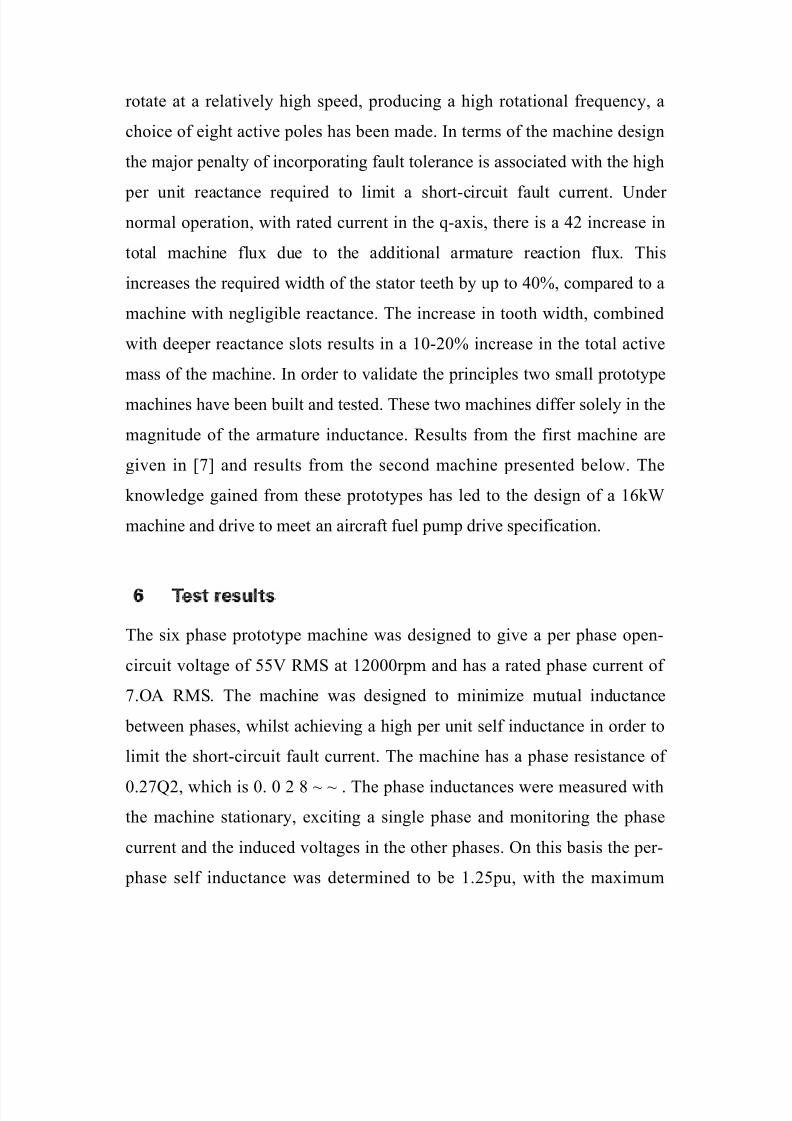
monitored. The no-load terminal voltage of three physically adjacent phases
is shown in Fig. 4. Note that because the three phases are isolated some third
harmonic components of voltage are evident.
8/7/2019 Fault Tolerant Permenant Magnet Machine Drives
http://slidepdf.com/reader/full/fault-tolerant-permenant-magnet-machine-drives 16/21
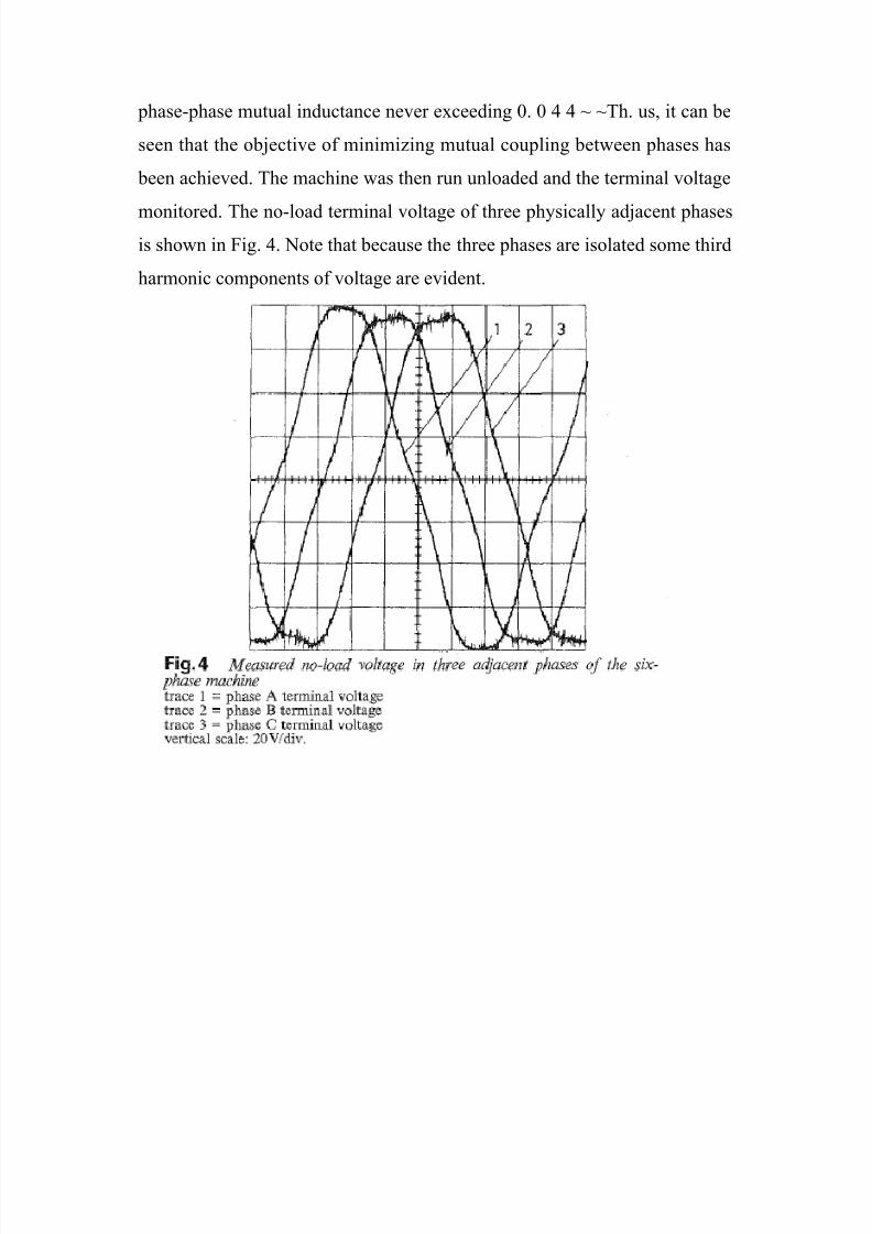
The test was then repeated, but with one phase shorted at its terminals.
These results, along with the current in the shorted phase are given in Fig. 5.
From comparison with Fig. 4 it is clear that the terminal voltage of the
unfaulted phases is virtually unaffected by the faulted phase current. The
RMS fault current is equal to the design value. Note that the fault current
lags the open-circuit voltage of that phase by 90", as the fault current is
predominantly limited by the phase inductance. The machine can operate
indefinitely in this condition, with the other phases still capab
generating torque, so that the ability to withstand a short circuit across any
one phase has been
demonstrated.
8/7/2019 Fault Tolerant Permenant Magnet Machine Drives
http://slidepdf.com/reader/full/fault-tolerant-permenant-magnet-machine-drives 17/21
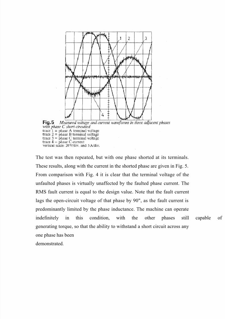
Particular emphasis has been placed upon a power device short-circuit
failure, as this imposes the most arduous conditions upon the drive.
8/7/2019 Fault Tolerant Permenant Magnet Machine Drives
http://slidepdf.com/reader/full/fault-tolerant-permenant-magnet-machine-drives 18/21
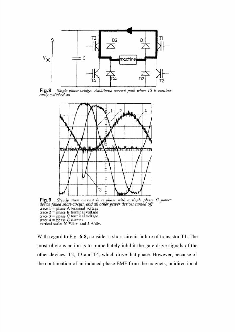
With regard to Fig. 6-8, consider a short-circuit failure of transistor T1. The
most obvious action is to immediately inhibit the gate drive signals of the
other devices, T2, T3 and T4, which drive that phase. However, because of
the continuation of an induced phase EMF from the magnets, unidirectional
8/7/2019 Fault Tolerant Permenant Magnet Machine Drives
http://slidepdf.com/reader/full/fault-tolerant-permenant-magnet-machine-drives 19/21
current continues to flow through the failed device, T1, and the diode, D3, as
shown in Fig. 7. Fig. 9 shows measurements of the prototype machine with
one phase failed in this manner. This diagram shows how the current in the
faulted phase is unidirectional with an AC component of approximately the
same peak magnitude as the DC component. A better strategy for dealing
with this fault is to continuously hold on transistor T3, so that the winding is
effectively shorted at the terminals, and giving the additional current path
shown in Fig. 8. The faulted phase current is as in the winding terminal
short-circuit shown in Fig. 5, and no longer contains any DC component.
The RMS current in the phase winding and in the faulted device is reduced
by 43 and the peak current halved. However, in order to take this action it is
essential that the fault is both quickly and accurately identified [6].
This paper has discussed the requirements for a fault tolerant permanent
magnet machine drive. The work has shown that the machine should bedriven from separate single phase bridges, and must be capab
withstanding a short-circuit terminal fault. A design topology has been
produced in which there is effective magnetic, thermal and physical isolation
between phases. This has been demonstrated by a series of tests performed
upon a small six phase prototype machine. The machine is capable of
withstanding open and short-circuit terminal conditions, with the unfaulted
phases continuing to deliver torque. The necessary action required to deal
with adjacent turn short-circuits has also been discussed. Remedial converter
action to control a phase with a short-circuit power device has also been
discussed and demonstrated.
8/7/2019 Fault Tolerant Permenant Magnet Machine Drives
http://slidepdf.com/reader/full/fault-tolerant-permenant-magnet-machine-drives 20/21
1. RICHTER, E.: ‘Switched reluctance machines for high performance
operations in a harsh environment - a review paper’. Proceedings of the
ICEM Boston, MA, 1990
2. RICHTER, E.: ‘High temperature switched reluctance motors
generators for future aircraft engine applications’. Proceedings of the
American control conference, Atlanta, June 1988, pp. 1846--1851
3. STEPHENS, C.M.: ‘Fault detection and management system for fault-
tolerant switched reluctance motor drives’, IEEE Trans. Ind.
4. JACK, A.G., and MECROW, B.C.: ‘Safety critical drives for aerospace
applications’. Proceedings of the ICEM 1994, Paris, 1994, Appl., NOV.
1991, 27, (6), pp. 1098-1102 Vol. 1, pp. 91-96
5. JAHNS, T.M.: ‘Improved reliability in solid state AC drives by 7
MECROW, B.C., JACK, A.G., and HAYLOCK, J.A.: ‘Fault tolerant
permanent magnet machine drives’. IEE 7th international conference on
Electrical machines and drives, Oxford, 1995, pp. means of multiple
independent phase-drive units’, IEEE Trans., May 1980, IAS-16, (3), pp.
321-331
6. CRAIG, E., MECROW, B.C., ATKINSON, D.J.,and JACK, A.G.: ‘A
fault detection procedure for single phase bridge converters’. E
Conference ’93, Brighton, 1993, Vol. 4, pp. 466-471
7. MECROW, B.C., JACK, A.G., and HAYLOCK, J.A.: ‘Fault tolerant
permanent magnet machine drives’. IEE 7th international conference on
Electrical machines and drives, Oxford, 1995, pp.433-467.

8/7/2019 Fault Tolerant Permenant Magnet Machine Drives
http://slidepdf.com/reader/full/fault-tolerant-permenant-magnet-machine-drives 21/21
Document By
SANTOSH BHARADWAJ REDDY
Email: [email protected]
Engineeringpapers.blogspot.com
More Papers and Presentations available on above site