Embed Size (px)
Citation preview
1 Rev 2.1‐3/23/15‐AL
955 Benton Ave., Winslow, ME 04901 Phone: 1-877-564-6697 Fax: 1-800-738-6314 Email: [email protected] Web Site: Johnnyseeds.com
Building the Modular Moveable Cathedral Tunnel Designed By Eliot Coleman at Four Season Farm
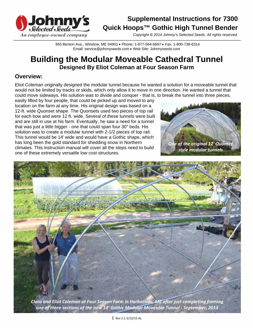
Overview: Eliot Coleman originally designed the modular tunnel because he wanted a solution for a moveable tunnel that would not be limited by tracks or skids, which only allow it to move in one direction. He wanted a tunnel that could move sideways. His solution was to divide and conquer - that is, to break the tunnel into three pieces, easily lifted by four people, that could be picked up and moved to any location on the farm at any time. His original design was based on a 12-ft. wide Quonset shape. The Quonsets used two pieces of top railfor each bow and were 12 ft. wide. Several of these tunnels were builtand are still in use at his farm. Eventually, he saw a need for a tunnelthat was just a little bigger - one that could span four 30" beds. Hissolution was to create a modular tunnel with 2-1/2 pieces of top rail.This tunnel would be 14' wide and would have a Gothic shape, whichhas long been the gold standard for shedding snow in Northernclimates. This instruction manual will cover all the steps need to buildone of these extremely versatile low cost structures.
Clara and Eliot Coleman at Four Season Farm in Harborside, ME after just completing framing one of three sections of the new 14' Gothic Modular Moveable Tunnel ‐ September, 2013
Supplemental Instructions for 7300 Quick Hoops™ Gothic High Tunnel Bender
Copyright © 2014 Johnny’s Selected Seeds. All rights reserved.
One of the original 12' Quonset style modular tunnels

2 Rev 2.1‐3/23/15‐AL
Commercial Use:
You can build your Modular
Cathedral Tunnel with as many
moveable modules as you like.
Each module will be self contained
and can be carried easily by four
people. This has numerous
commercial applications, including
enhanced flexibility for season
extension and overwintering, but
can also be used for solarization
of the soil by enclosing the tunnel
for a time without venting in order
to kill weeds in a particular section
of the field.
Home Garden Use:
Home gardeners can also use benefit from this
system as a single 14' x 16' module is a very
convenient size for a backyard greenhouse.
Moving the Modular Cathedral into place in November over crops started in fall under Quick Hoops low tunnels
Those same crops in April, ready for harvest.
3 Rev 2.1‐3/23/15‐AL
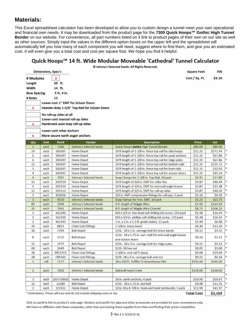
Materials: This Excel spreadsheet calculator has been developed to allow you to custom design a tunnel meet your own operational and financial own needs. It may be downloaded from the product page for the 7300 Quick Hoops™ Gothic High Tunnel Bender on our website. For convenience, all part numbers listed on it link to product pages of their own on our site as well as other sources. Simply input the values in the different option boxes on the upper left and the spreadsheet will automatically tell you how many of each component you will need, suggest where to find them, and give you an estimated cost. It will even give you a total cost and cost per square foot. We hope you find it helpful.
4 Rev 2.1‐3/23/15‐AL
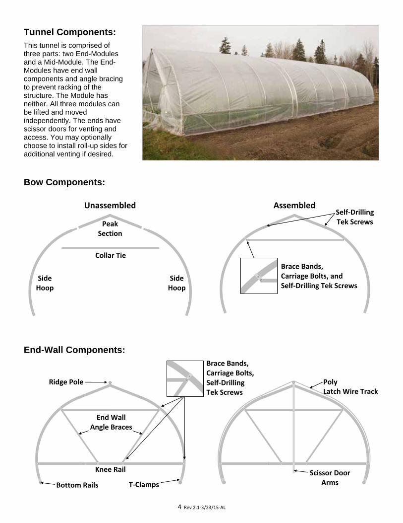
Tunnel Components: This tunnel is comprised of three parts: two End-Modules and a Mid-Module. The End-Modules have end wall components and angle bracing to prevent racking of the structure. The Module has neither. All three modules can be lifted and moved independently. The ends have scissor doors for venting and access. You may optionally choose to install roll-up sides for additional venting if desired.
Bow Components:
End-Wall Components:
Side Hoop
Side Hoop
Ridge Pole
Knee Rail
End Wall Angle Braces
T‐Clamps Bottom Rails
Scissor Door Arms
Poly Latch Wire Track
Brace Bands, Carriage Bolts, Self‐Drilling Tek Screws
Collar Tie
Peak Section
Unassembled Assembled Self‐Drilling Tek Screws
Brace Bands, Carriage Bolts, and Self‐Drilling Tek Screws
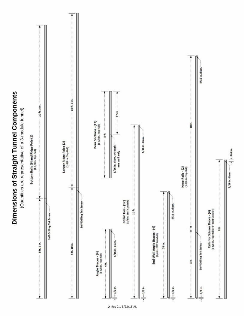
5 Rev 2.1‐3/23/15‐AL
Dim
ensi
on
s o
f S
trai
gh
t T
un
nel
Co
mp
on
ents
(Q
uant
ities
are
rep
rese
ntat
ive
of a
3-m
odul
e tu
nnel
)
6 Rev 2.1‐3/23/15‐AL
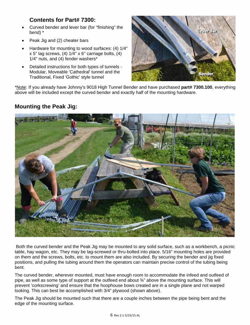
Contents for Part# 7300: Curved bender and lever bar (for “finishing” the
bend) *
Peak Jig and (2) cheater bars
Hardware for mounting to wood surfaces: (4) 1/4" x 5" lag screws, (4) 1/4" x 6" carriage bolts, (4) 1/4" nuts, and (4) fender washers*
Detailed instructions for both types of tunnels - Modular, Moveable 'Cathedral' tunnel and the Traditional, Fixed 'Gothic' style tunnel
*Note: If you already have Johnny's 9018 High Tunnel Bender and have purchased part# 7300.100, everything above will be included except the curved bender and exactly half of the mounting hardware.
Mounting the Peak Jig:
Both the curved bender and the Peak Jig may be mounted to any solid surface, such as a workbench, a picnic table, hay wagon, etc. They may be lag-screwed or thru-bolted into place. 5/16” mounting holes are provided on them and the screws, bolts, etc. to mount them are also included. By securing the bender and jig fixed positions, and pulling the tubing around them the operators can maintain precise control of the tubing being bent.
The curved bender, wherever mounted, must have enough room to accommodate the infeed and outfeed of pipe, as well as some type of support at the outfeed end about ¾” above the mounting surface. This will prevent ‘corkscrewing’ and ensure that the hoophouse bows created are in a single plane and not warped looking. This can best be accomplished with 3/4” plywood (shown above).
The Peak Jig should be mounted such that there are a couple inches between the pipe being bent and the edge of the mounting surface.
BBBeeennndddeeerrr
LLLeeevvveeerrr BBBaaarrr
7 Rev 2.1‐3/23/15‐AL
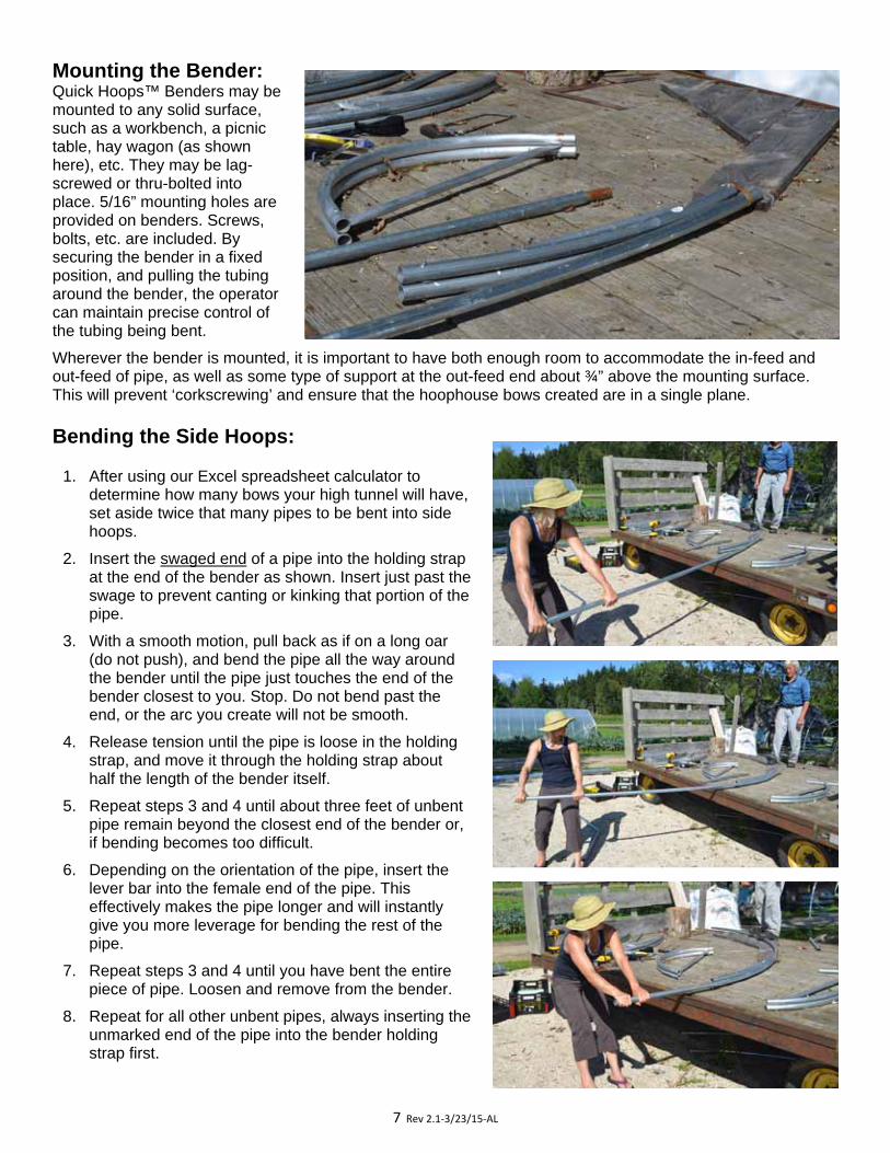
Mounting the Bender: Quick Hoops™ Benders may be mounted to any solid surface, such as a workbench, a picnic table, hay wagon (as shown here), etc. They may be lag-screwed or thru-bolted into place. 5/16” mounting holes are provided on benders. Screws, bolts, etc. are included. By securing the bender in a fixed position, and pulling the tubing around the bender, the operator can maintain precise control of the tubing being bent.
Wherever the bender is mounted, it is important to have both enough room to accommodate the in-feed and out-feed of pipe, as well as some type of support at the out-feed end about ¾” above the mounting surface. This will prevent ‘corkscrewing’ and ensure that the hoophouse bows created are in a single plane.
Bending the Side Hoops:
1. After using our Excel spreadsheet calculator to determine how many bows your high tunnel will have, set aside twice that many pipes to be bent into side hoops.
2. Insert the swaged end of a pipe into the holding strap at the end of the bender as shown. Insert just past the swage to prevent canting or kinking that portion of the pipe.
3. With a smooth motion, pull back as if on a long oar (do not push), and bend the pipe all the way around the bender until the pipe just touches the end of the bender closest to you. Stop. Do not bend past the end, or the arc you create will not be smooth.
4. Release tension until the pipe is loose in the holding strap, and move it through the holding strap about half the length of the bender itself.
5. Repeat steps 3 and 4 until about three feet of unbent pipe remain beyond the closest end of the bender or, if bending becomes too difficult.
6. Depending on the orientation of the pipe, insert the lever bar into the female end of the pipe. This effectively makes the pipe longer and will instantly give you more leverage for bending the rest of the pipe.
7. Repeat steps 3 and 4 until you have bent the entire piece of pipe. Loosen and remove from the bender.
8. Repeat for all other unbent pipes, always inserting the unmarked end of the pipe into the bender holding strap first.
8 Rev 2.1‐3/23/15‐AL
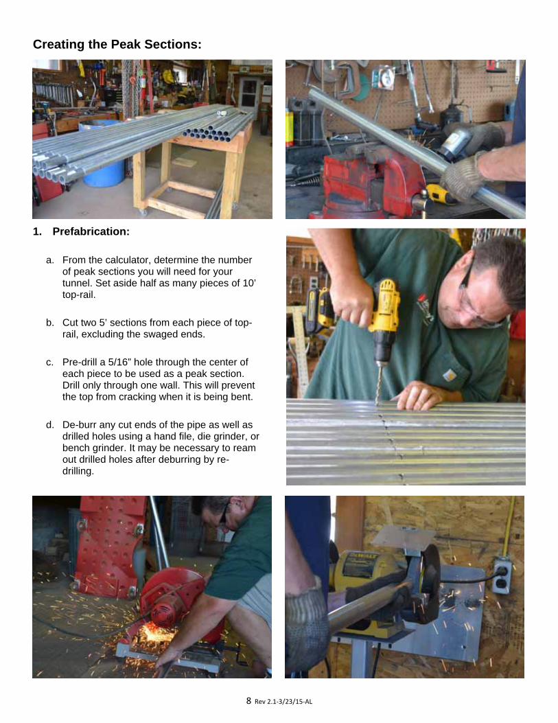
Creating the Peak Sections:
1. Prefabrication:
a. From the calculator, determine the number of peak sections you will need for your tunnel. Set aside half as many pieces of 10’ top-rail.
b. Cut two 5’ sections from each piece of top-rail, excluding the swaged ends.
c. Pre-drill a 5/16” hole through the center of each piece to be used as a peak section. Drill only through one wall. This will prevent the top from cracking when it is being bent.
d. De-burr any cut ends of the pipe as well as drilled holes using a hand file, die grinder, or bench grinder. It may be necessary to ream out drilled holes after deburring by re-drilling.
9 Rev 2.1‐3/23/15‐AL
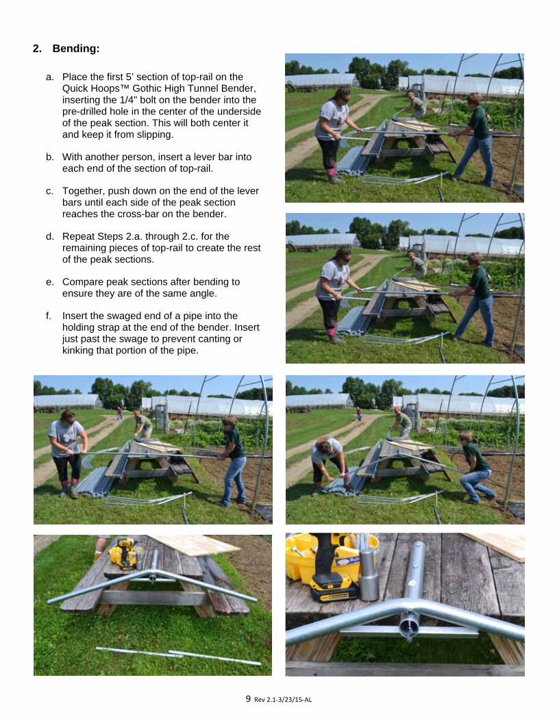
2. Bending:
a. Place the first 5’ section of top-rail on the Quick Hoops™ Gothic High Tunnel Bender, inserting the 1/4" bolt on the bender into the pre-drilled hole in the center of the underside of the peak section. This will both center it and keep it from slipping.
b. With another person, insert a lever bar into each end of the section of top-rail.
c. Together, push down on the end of the lever bars until each side of the peak section reaches the cross-bar on the bender.
d. Repeat Steps 2.a. through 2.c. for the remaining pieces of top-rail to create the rest of the peak sections.
e. Compare peak sections after bending to ensure they are of the same angle.
f. Insert the swaged end of a pipe into the holding strap at the end of the bender. Insert just past the swage to prevent canting or kinking that portion of the pipe.
10 Rev 2.1‐3/23/15‐AL
Constructing the Bows:
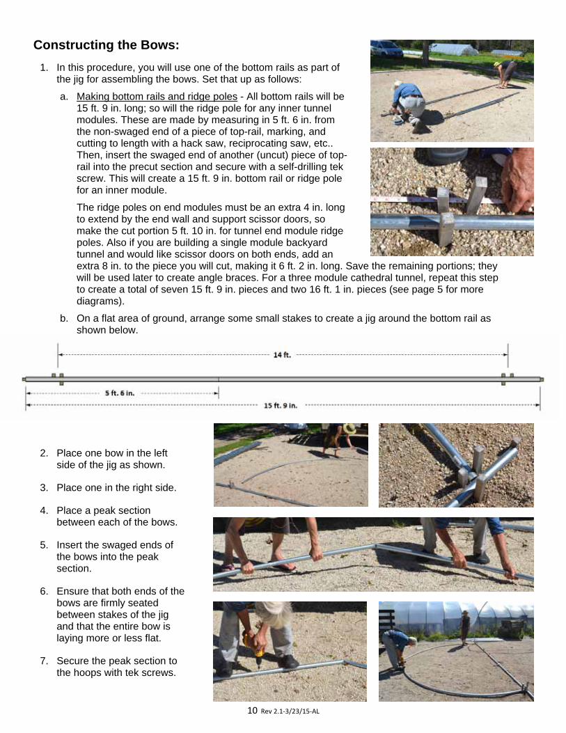
1. In this procedure, you will use one of the bottom rails as part of the jig for assembling the bows. Set that up as follows:
a. Making bottom rails and ridge poles - All bottom rails will be 15 ft. 9 in. long; so will the ridge pole for any inner tunnel modules. These are made by measuring in 5 ft. 6 in. from the non-swaged end of a piece of top-rail, marking, and cutting to length with a hack saw, reciprocating saw, etc.. Then, insert the swaged end of another (uncut) piece of top-rail into the precut section and secure with a self-drilling tek screw. This will create a 15 ft. 9 in. bottom rail or ridge pole for an inner module.
The ridge poles on end modules must be an extra 4 in. long to extend by the end wall and support scissor doors, so make the cut portion 5 ft. 10 in. for tunnel end module ridge poles. Also if you are building a single module backyard tunnel and would like scissor doors on both ends, add an extra 8 in. to the piece you will cut, making it 6 ft. 2 in. long. Save the remaining portions; they will be used later to create angle braces. For a three module cathedral tunnel, repeat this step to create a total of seven 15 ft. 9 in. pieces and two 16 ft. 1 in. pieces (see page 5 for more diagrams).
b. On a flat area of ground, arrange some small stakes to create a jig around the bottom rail as shown below.
2. Place one bow in the left side of the jig as shown.
3. Place one in the right side.
4. Place a peak section between each of the bows.
5. Insert the swaged ends of the bows into the peak section.
6. Ensure that both ends of the bows are firmly seated between stakes of the jig and that the entire bow is laying more or less flat.
7. Secure the peak section to the hoops with tek screws.
11 Rev 2.1‐3/23/15‐AL
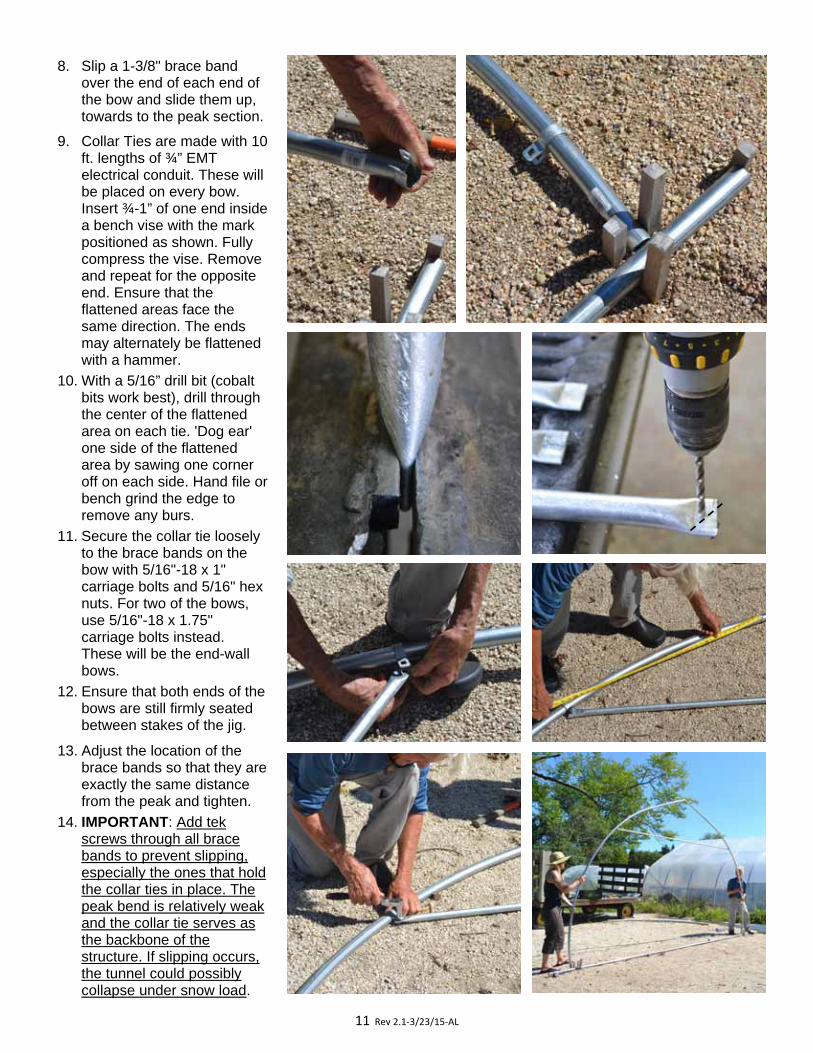
8. Slip a 1-3/8" brace band over the end of each end of the bow and slide them up, towards to the peak section.
9. Collar Ties are made with 10 ft. lengths of ¾” EMT electrical conduit. These will be placed on every bow. Insert ¾-1” of one end inside a bench vise with the mark positioned as shown. Fully compress the vise. Remove and repeat for the opposite end. Ensure that the flattened areas face the same direction. The ends may alternately be flattened with a hammer.
10. With a 5/16” drill bit (cobalt bits work best), drill through the center of the flattened area on each tie. 'Dog ear' one side of the flattened area by sawing one corner off on each side. Hand file or bench grind the edge to remove any burs.
11. Secure the collar tie loosely to the brace bands on the bow with 5/16"-18 x 1" carriage bolts and 5/16" hex nuts. For two of the bows, use 5/16"-18 x 1.75" carriage bolts instead. These will be the end-wall bows.
12. Ensure that both ends of the bows are still firmly seated between stakes of the jig.
13. Adjust the location of the brace bands so that they are exactly the same distance from the peak and tighten.
14. IMPORTANT: Add tek screws through all brace bands to prevent slipping, especially the ones that hold the collar ties in place. The peak bend is relatively weak and the collar tie serves as the backbone of the structure. If slipping occurs, the tunnel could possibly collapse under snow load.
12 Rev 2.1‐3/23/15‐AL
Assembling the Frame:
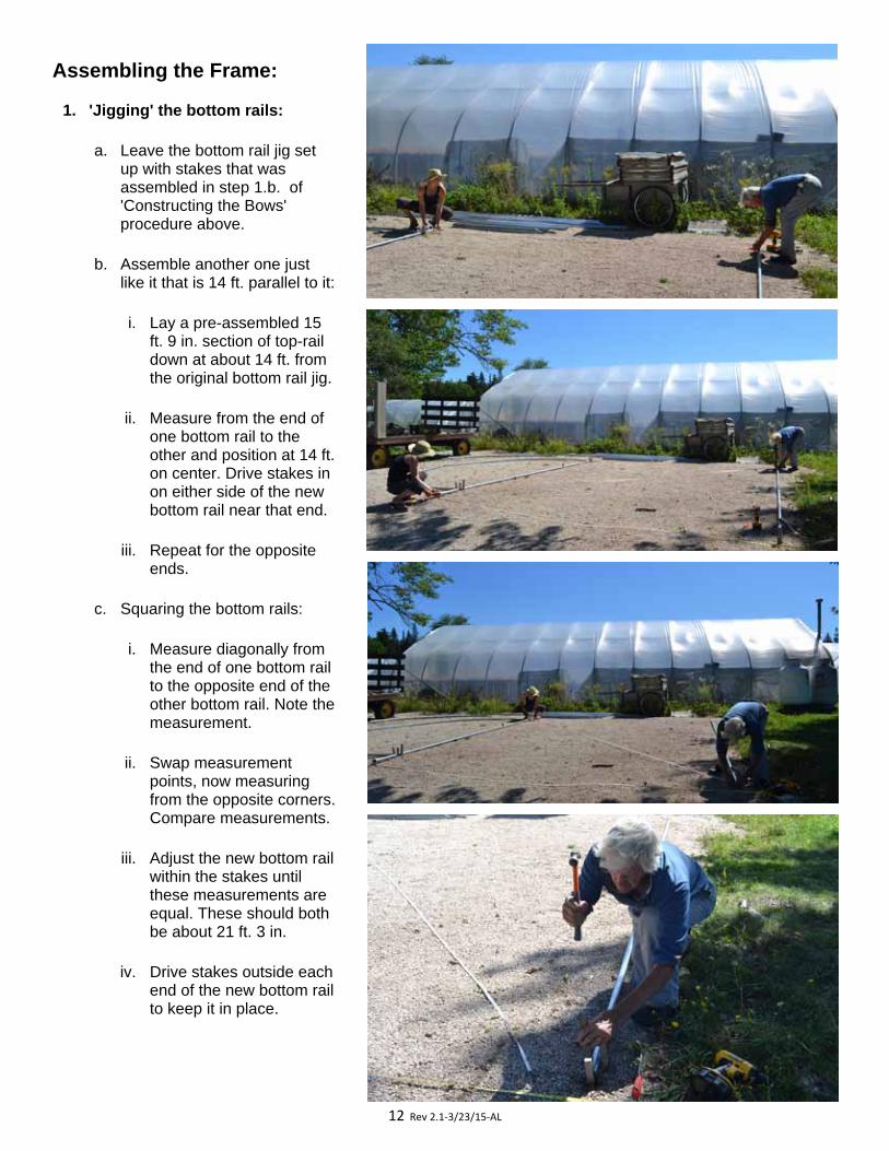
1. 'Jigging' the bottom rails:
a. Leave the bottom rail jig set up with stakes that was assembled in step 1.b. of 'Constructing the Bows' procedure above.
b. Assemble another one just like it that is 14 ft. parallel to it:
i. Lay a pre-assembled 15 ft. 9 in. section of top-rail down at about 14 ft. from the original bottom rail jig.
ii. Measure from the end of one bottom rail to the other and position at 14 ft. on center. Drive stakes in on either side of the new bottom rail near that end.
iii. Repeat for the opposite ends.
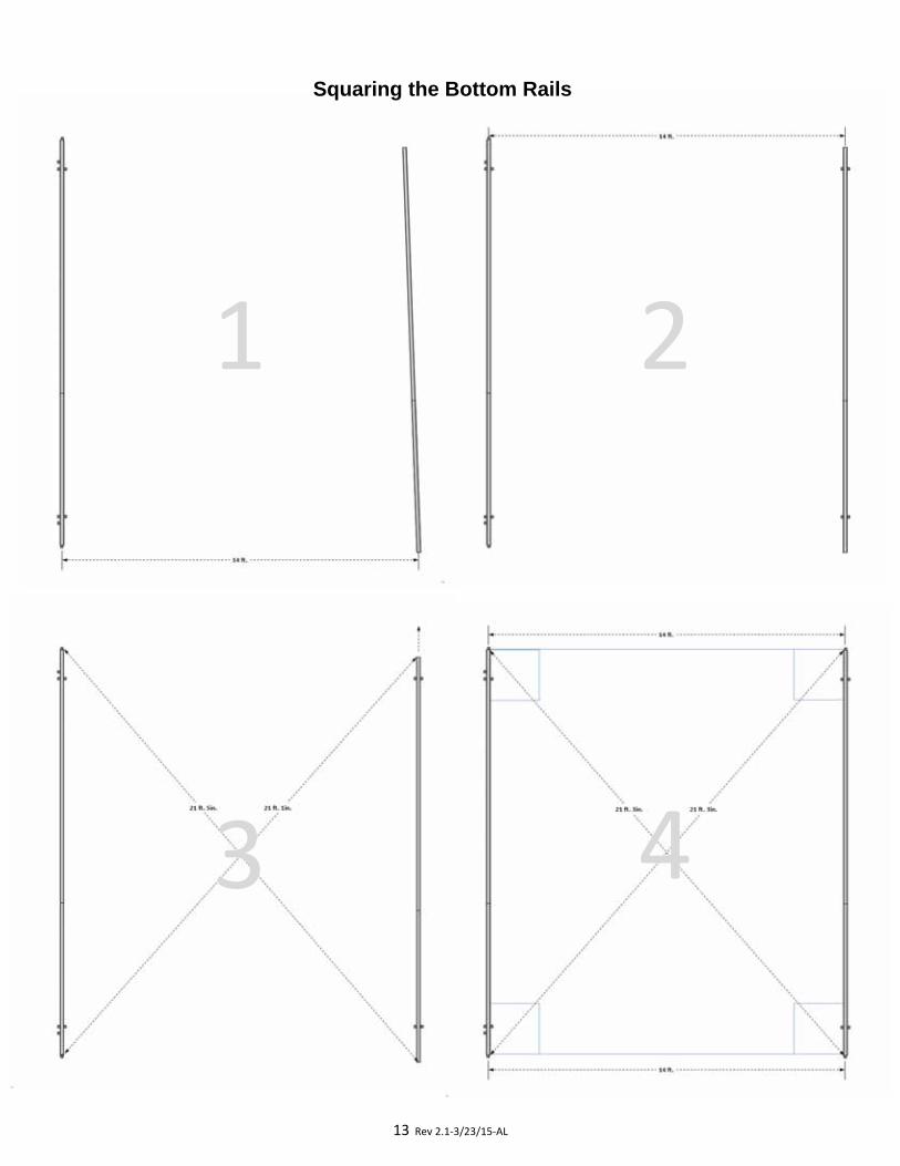
c. Squaring the bottom rails:
i. Measure diagonally from the end of one bottom rail to the opposite end of the other bottom rail. Note the measurement.
ii. Swap measurement points, now measuring from the opposite corners. Compare measurements.
iii. Adjust the new bottom rail within the stakes until these measurements are equal. These should both be about 21 ft. 3 in.
iv. Drive stakes outside each end of the new bottom rail to keep it in place.
13 Rev 2.1‐3/23/15‐AL
Squaring the Bottom Rails
1
2
3
4
14 Rev 2.1‐3/23/15‐AL
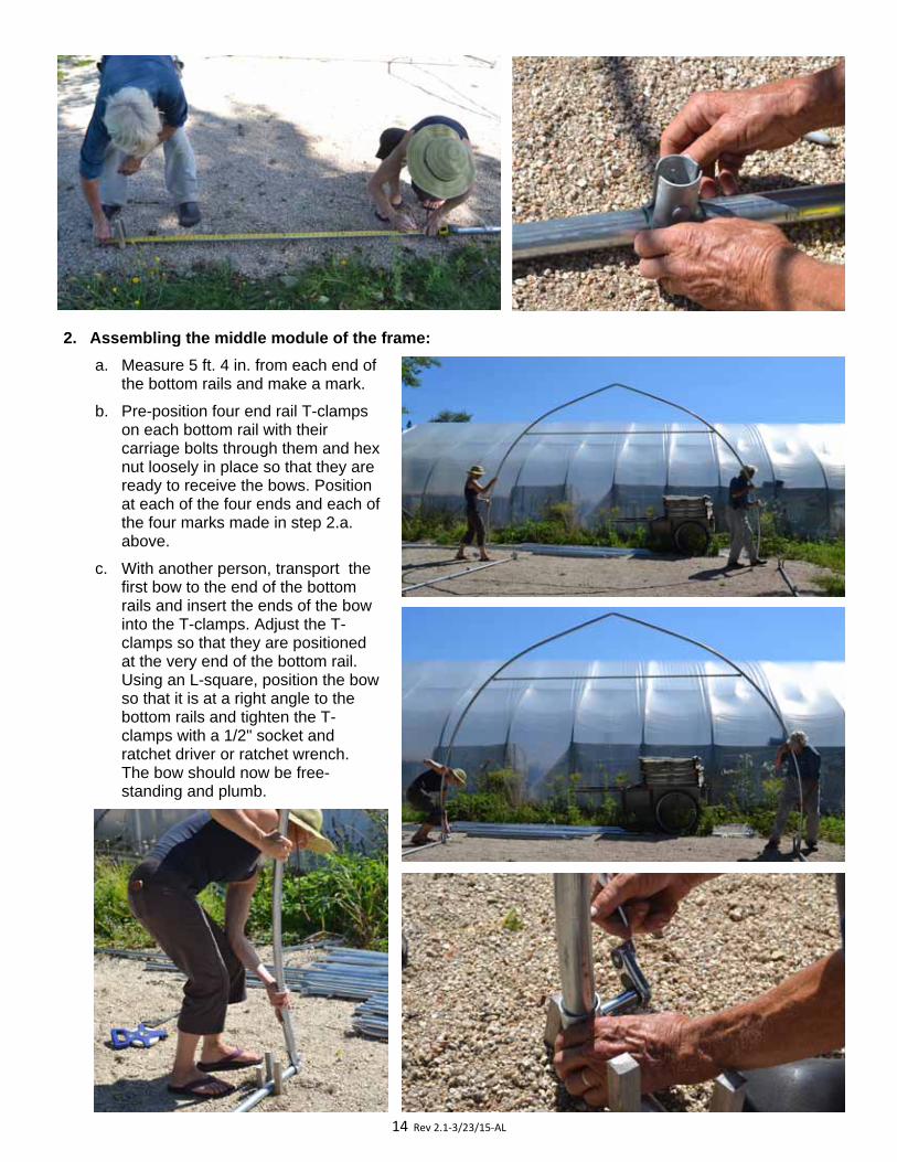
2. Assembling the middle module of the frame:
a. Measure 5 ft. 4 in. from each end of the bottom rails and make a mark.
b. Pre-position four end rail T-clamps on each bottom rail with their carriage bolts through them and hex nut loosely in place so that they are ready to receive the bows. Position at each of the four ends and each of the four marks made in step 2.a. above.
c. With another person, transport the first bow to the end of the bottom rails and insert the ends of the bow into the T-clamps. Adjust the T-clamps so that they are positioned at the very end of the bottom rail. Using an L-square, position the bow so that it is at a right angle to the bottom rails and tighten the T-clamps with a 1/2" socket and ratchet driver or ratchet wrench. The bow should now be free-standing and plumb.
15 Rev 2.1‐3/23/15‐AL
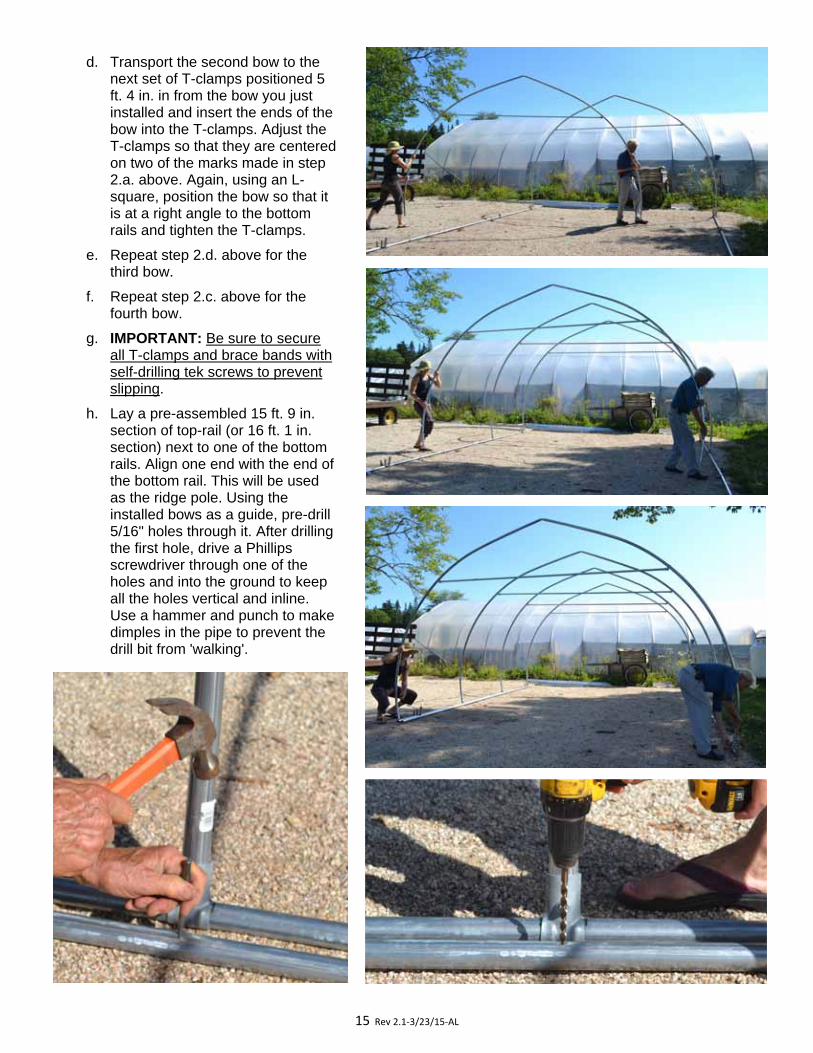
d. Transport the second bow to the next set of T-clamps positioned 5 ft. 4 in. in from the bow you just installed and insert the ends of the bow into the T-clamps. Adjust the T-clamps so that they are centered on two of the marks made in step 2.a. above. Again, using an L-square, position the bow so that it is at a right angle to the bottom rails and tighten the T-clamps.
e. Repeat step 2.d. above for the third bow.
f. Repeat step 2.c. above for the fourth bow.
g. IMPORTANT: Be sure to secure all T-clamps and brace bands with self-drilling tek screws to prevent slipping.
h. Lay a pre-assembled 15 ft. 9 in. section of top-rail (or 16 ft. 1 in. section) next to one of the bottom rails. Align one end with the end of the bottom rail. This will be used as the ridge pole. Using the installed bows as a guide, pre-drill 5/16" holes through it. After drilling the first hole, drive a Phillips screwdriver through one of the holes and into the ground to keep all the holes vertical and inline. Use a hammer and punch to make dimples in the pipe to prevent the drill bit from 'walking'.
16 Rev 2.1‐3/23/15‐AL
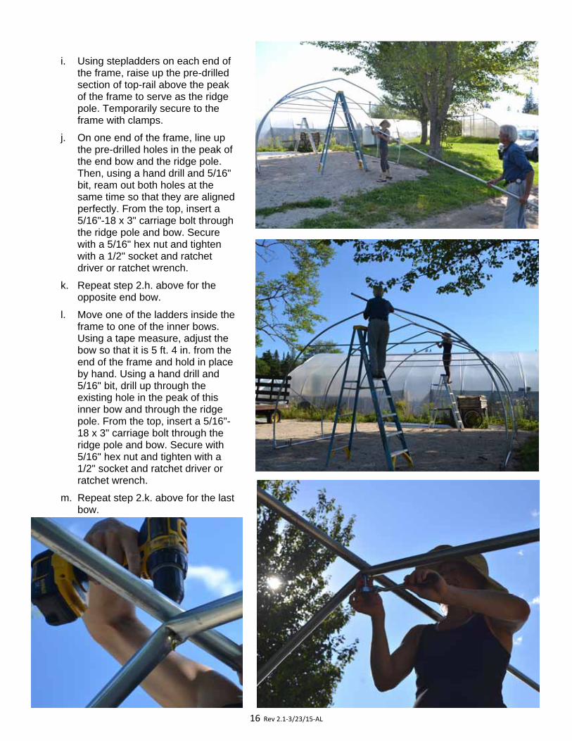
i. Using stepladders on each end of the frame, raise up the pre-drilled section of top-rail above the peak of the frame to serve as the ridge pole. Temporarily secure to the frame with clamps.
j. On one end of the frame, line up the pre-drilled holes in the peak of the end bow and the ridge pole. Then, using a hand drill and 5/16" bit, ream out both holes at the same time so that they are aligned perfectly. From the top, insert a 5/16"-18 x 3" carriage bolt through the ridge pole and bow. Secure with a 5/16" hex nut and tighten with a 1/2" socket and ratchet driver or ratchet wrench.
k. Repeat step 2.h. above for the opposite end bow.
l. Move one of the ladders inside the frame to one of the inner bows. Using a tape measure, adjust the bow so that it is 5 ft. 4 in. from the end of the frame and hold in place by hand. Using a hand drill and 5/16" bit, drill up through the existing hole in the peak of this inner bow and through the ridge pole. From the top, insert a 5/16"-18 x 3" carriage bolt through the ridge pole and bow. Secure with 5/16" hex nut and tighten with a 1/2" socket and ratchet driver or ratchet wrench.
m. Repeat step 2.k. above for the last bow.
17 Rev 2.1‐3/23/15‐AL
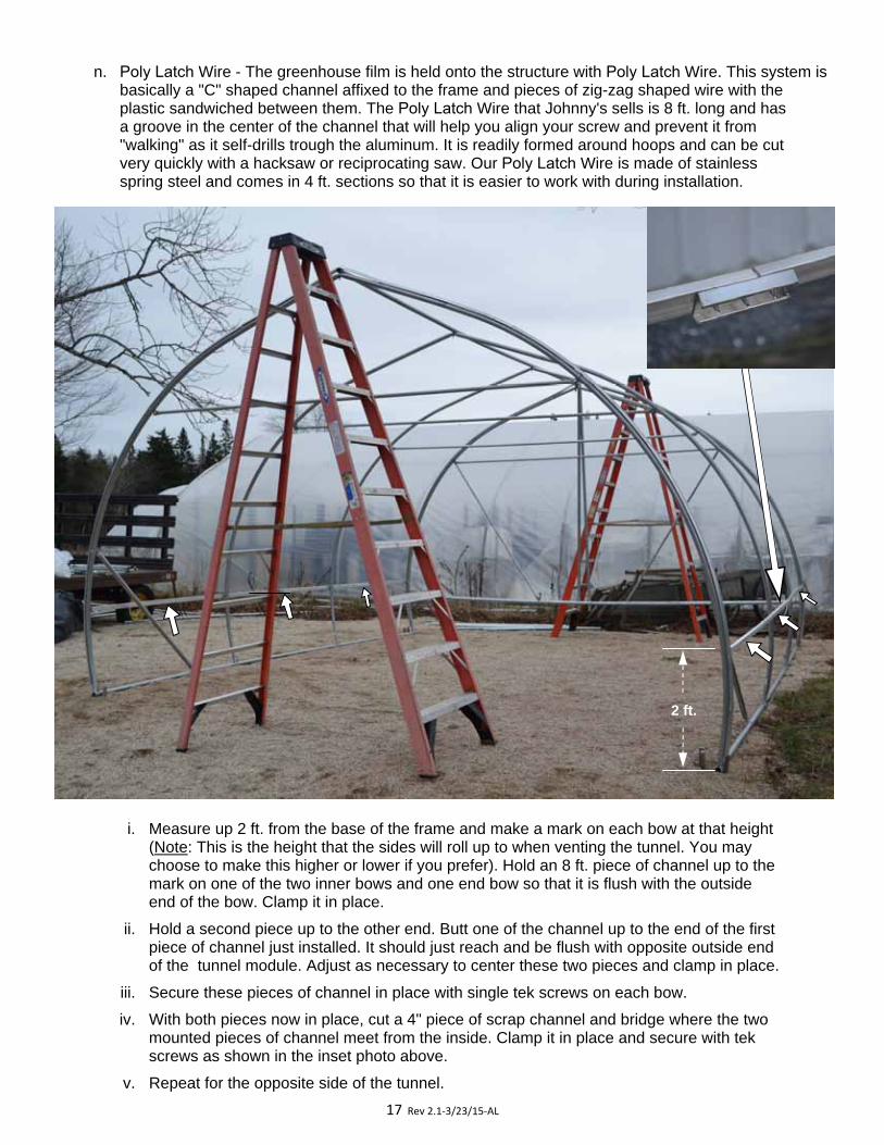
n. Poly Latch Wire - The greenhouse film is held onto the structure with Poly Latch Wire. This system isbasically a "C" shaped channel affixed to the frame and pieces of zig-zag shaped wire with the plastic sandwiched between them. The Poly Latch Wire that Johnny's sells is 8 ft. long and has a groove in the center of the channel that will help you align your screw and prevent it from"walking" as it self-drills trough the aluminum. It is readily formed around hoops and can be cut very quickly with a hacksaw or reciprocating saw. Our Poly Latch Wire is made of stainless spring steel and comes in 4 ft. sections so that it is easier to work with during installation.
i. Measure up 2 ft. from the base of the frame and make a mark on each bow at that height(Note: This is the height that the sides will roll up to when venting the tunnel. You maychoose to make this higher or lower if you prefer). Hold an 8 ft. piece of channel up to themark on one of the two inner bows and one end bow so that it is flush with the outsideend of the bow. Clamp it in place.
ii. Hold a second piece up to the other end. Butt one of the channel up to the end of the firstpiece of channel just installed. It should just reach and be flush with opposite outside endof the tunnel module. Adjust as necessary to center these two pieces and clamp in place.
iii. Secure these pieces of channel in place with single tek screws on each bow.
iv. With both pieces now in place, cut a 4" piece of scrap channel and bridge where the twomounted pieces of channel meet from the inside. Clamp it in place and secure with tekscrews as shown in the inset photo above.
v. Repeat for the opposite side of the tunnel.
2 ft.
18 Rev 2.1‐3/23/15‐AL
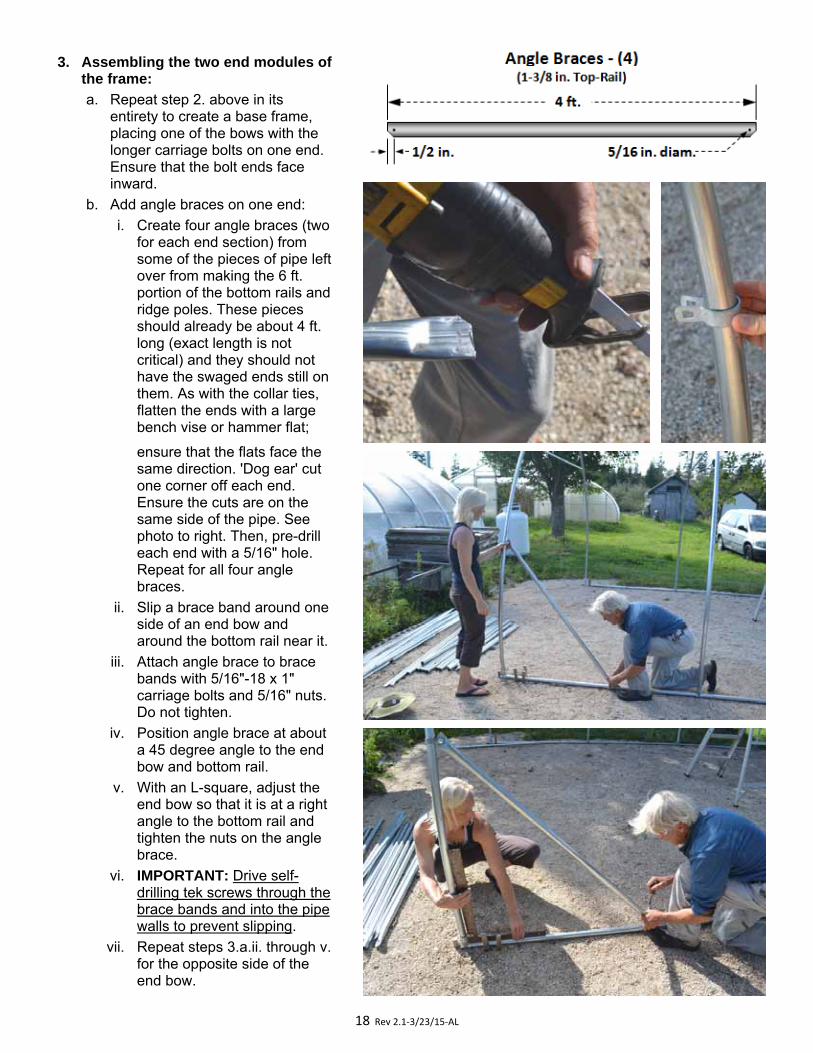
3. Assembling the two end modules of the frame:
a. Repeat step 2. above in its entirety to create a base frame, placing one of the bows with the longer carriage bolts on one end. Ensure that the bolt ends face inward.
b. Add angle braces on one end: i. Create four angle braces (two
for each end section) from some of the pieces of pipe left over from making the 6 ft. portion of the bottom rails and ridge poles. These pieces should already be about 4 ft. long (exact length is not critical) and they should not have the swaged ends still on them. As with the collar ties, flatten the ends with a large bench vise or hammer flat;
ensure that the flats face the same direction. 'Dog ear' cut one corner off each end. Ensure the cuts are on the same side of the pipe. See photo to right. Then, pre-drill each end with a 5/16" hole. Repeat for all four angle braces.
ii. Slip a brace band around one side of an end bow and around the bottom rail near it.
iii. Attach angle brace to brace bands with 5/16"-18 x 1" carriage bolts and 5/16" nuts. Do not tighten.
iv. Position angle brace at about a 45 degree angle to the end bow and bottom rail.
v. With an L-square, adjust the end bow so that it is at a right angle to the bottom rail and tighten the nuts on the angle brace.
vi. IMPORTANT: Drive self-drilling tek screws through the brace bands and into the pipe walls to prevent slipping.
vii. Repeat steps 3.a.ii. through v. for the opposite side of the end bow.

19 Rev 2.1‐3/23/15‐AL
c. Frame the end wall as follows:
i. Knee Rails - Cut the swaged end off a 10 ft. piece of top rail. Measure 5 ft. from the end,mark, and cut. Flatten one end of each (the non-swaged end of the larger piece) with a largebench vise or hammer them flat. This time, 'dog ear' cut both corners off each end. Then,pre-drill each flattened end with a 5/16" hole about 1/2" from the end. Insert the swaged endof the other (uncut) 10 ft. piece of top-rail into the precut 5 ft. section, ensure that the flatsface the same direction, and secure with a self-drilling tek screw. Make two of these.
At the bottom of the "end-wall" bow (the one that will be on the outside end of the tunnel),measure up 18" from the bottom rail and make a mark. Slide a brace band over the bow ateach of the marks. Attach the knee rail to the brace bands with 5/16"-18 x 1" carriage boltsand 5/16" nuts, position vertically at each mark and tighten.
Ridge Pole
Knee Rail
End Wall Angle Braces
T‐Clamps Bottom Rails
Scissor Door Rails
Poly Latch Wire Track
20 Rev 2.1‐3/23/15‐AL
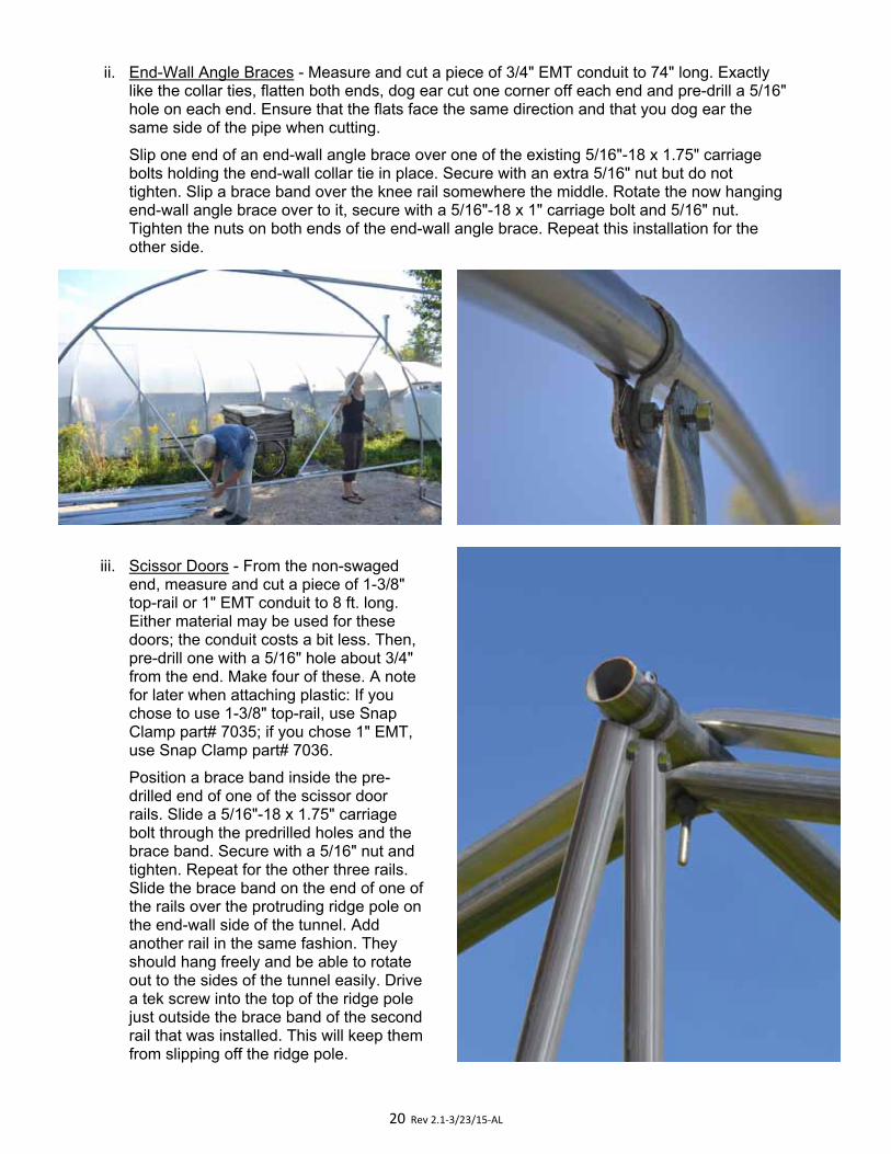
ii. End-Wall Angle Braces - Measure and cut a piece of 3/4" EMT conduit to 74" long. Exactly like the collar ties, flatten both ends, dog ear cut one corner off each end and pre-drill a 5/16" hole on each end. Ensure that the flats face the same direction and that you dog ear the same side of the pipe when cutting.
Slip one end of an end-wall angle brace over one of the existing 5/16"-18 x 1.75" carriage bolts holding the end-wall collar tie in place. Secure with an extra 5/16" nut but do not tighten. Slip a brace band over the knee rail somewhere the middle. Rotate the now hanging end-wall angle brace over to it, secure with a 5/16"-18 x 1" carriage bolt and 5/16" nut. Tighten the nuts on both ends of the end-wall angle brace. Repeat this installation for the other side.
iii. Scissor Doors - From the non-swaged end, measure and cut a piece of 1-3/8" top-rail or 1" EMT conduit to 8 ft. long. Either material may be used for these doors; the conduit costs a bit less. Then, pre-drill one with a 5/16" hole about 3/4" from the end. Make four of these. A note for later when attaching plastic: If you chose to use 1-3/8" top-rail, use Snap Clamp part# 7035; if you chose 1" EMT, use Snap Clamp part# 7036.
Position a brace band inside the pre-drilled end of one of the scissor door rails. Slide a 5/16"-18 x 1.75" carriage bolt through the predrilled holes and the brace band. Secure with a 5/16" nut and tighten. Repeat for the other three rails. Slide the brace band on the end of one of the rails over the protruding ridge pole on the end-wall side of the tunnel. Add another rail in the same fashion. They should hang freely and be able to rotate out to the sides of the tunnel easily. Drive a tek screw into the top of the ridge pole just outside the brace band of the second rail that was installed. This will keep them from slipping off the ridge pole.
21 Rev 2.1‐3/23/15‐AL
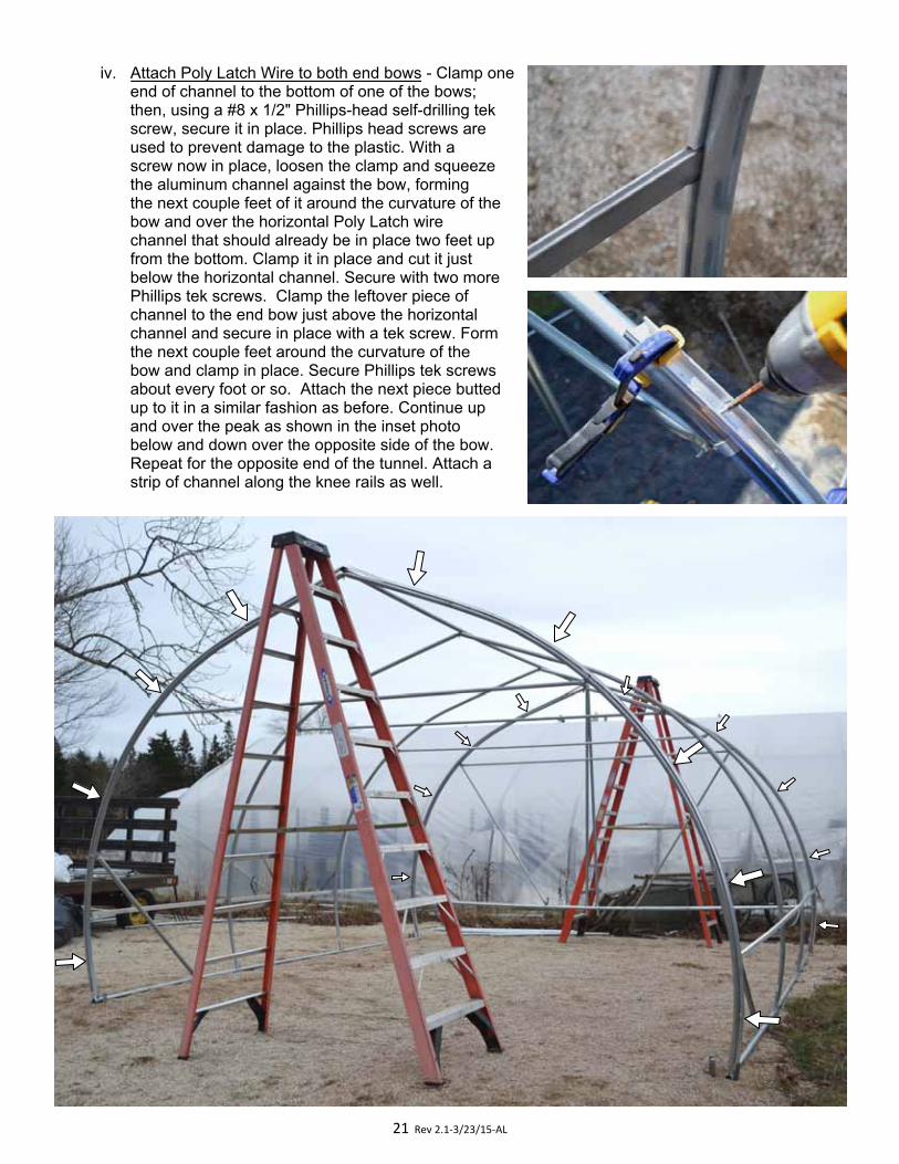
iv. Attach Poly Latch Wire to both end bows - Clamp oneend of channel to the bottom of one of the bows; then, using a #8 x 1/2" Phillips-head self-drilling tek screw, secure it in place. Phillips head screws are used to prevent damage to the plastic. With a screw now in place, loosen the clamp and squeeze the aluminum channel against the bow, forming the next couple feet of it around the curvature of the bow and over the horizontal Poly Latch wire channel that should already be in place two feet up from the bottom. Clamp it in place and cut it just below the horizontal channel. Secure with two more Phillips tek screws. Clamp the leftover piece of channel to the end bow just above the horizontal channel and secure in place with a tek screw. Form the next couple feet around the curvature of the bow and clamp in place. Secure Phillips tek screws about every foot or so. Attach the next piece butted up to it in a similar fashion as before. Continue up and over the peak as shown in the inset photo below and down over the opposite side of the bow. Repeat for the opposite end of the tunnel. Attach a strip of channel along the knee rails as well.
22 Rev 2.1‐3/23/15‐AL
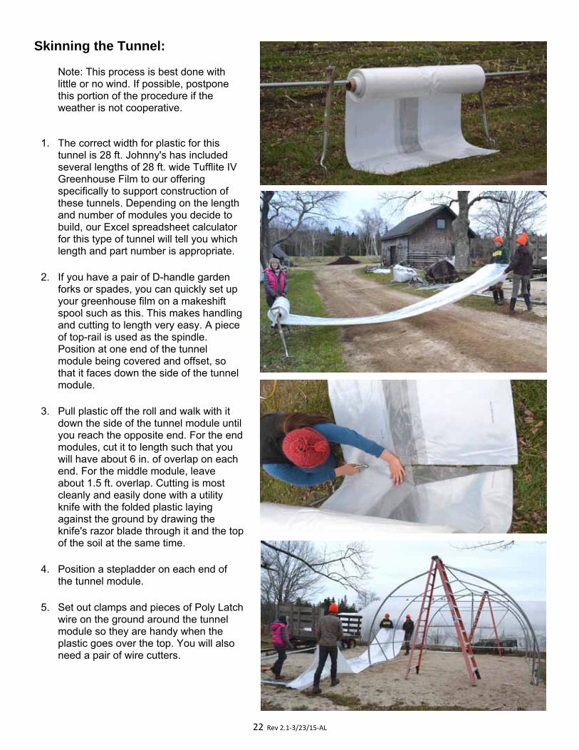
Skinning the Tunnel:
Note: This process is best done with little or no wind. If possible, postpone this portion of the procedure if the weather is not cooperative.
1. The correct width for plastic for this tunnel is 28 ft. Johnny's has included several lengths of 28 ft. wide Tufflite IV Greenhouse Film to our offering specifically to support construction of these tunnels. Depending on the length and number of modules you decide to build, our Excel spreadsheet calculator for this type of tunnel will tell you which length and part number is appropriate.
2. If you have a pair of D-handle garden forks or spades, you can quickly set up your greenhouse film on a makeshift spool such as this. This makes handling and cutting to length very easy. A piece of top-rail is used as the spindle. Position at one end of the tunnel module being covered and offset, so that it faces down the side of the tunnel module.
3. Pull plastic off the roll and walk with it down the side of the tunnel module until you reach the opposite end. For the end modules, cut it to length such that you will have about 6 in. of overlap on each end. For the middle module, leave about 1.5 ft. overlap. Cutting is most cleanly and easily done with a utility knife with the folded plastic laying against the ground by drawing the knife's razor blade through it and the top of the soil at the same time.
4. Position a stepladder on each end of the tunnel module.
5. Set out clamps and pieces of Poly Latch wire on the ground around the tunnel module so they are handy when the plastic goes over the top. You will also need a pair of wire cutters.
23 Rev 2.1‐3/23/15‐AL
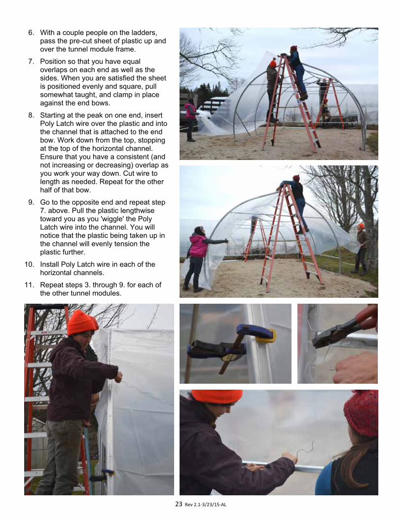
6. With a couple people on the ladders, pass the pre-cut sheet of plastic up and over the tunnel module frame.
7. Position so that you have equal overlaps on each end as well as the sides. When you are satisfied the sheet is positioned evenly and square, pull somewhat taught, and clamp in place against the end bows.
8. Starting at the peak on one end, insert Poly Latch wire over the plastic and into the channel that is attached to the end bow. Work down from the top, stopping at the top of the horizontal channel. Ensure that you have a consistent (and not increasing or decreasing) overlap as you work your way down. Cut wire to length as needed. Repeat for the other half of that bow.
9. Go to the opposite end and repeat step7. above. Pull the plastic lengthwise toward you as you 'wiggle' the Poly Latch wire into the channel. You will notice that the plastic being taken up in the channel will evenly tension the plastic further.
10. Install Poly Latch wire in each of the horizontal channels.
11. Repeat steps 3. through 9. for each of the other tunnel modules.
24 Rev 2.1‐3/23/15‐AL
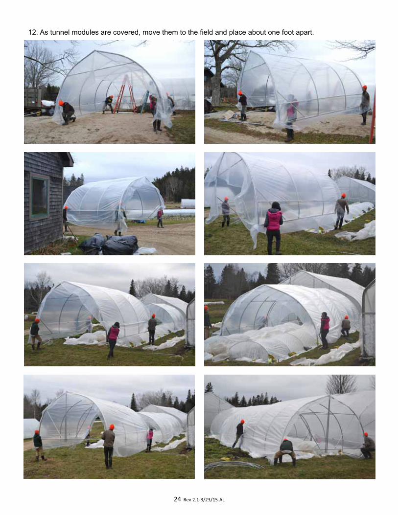
12. As tunnel modules are covered, move them to the field and place about one foot apart.
25 Rev 2.1‐3/23/15‐AL
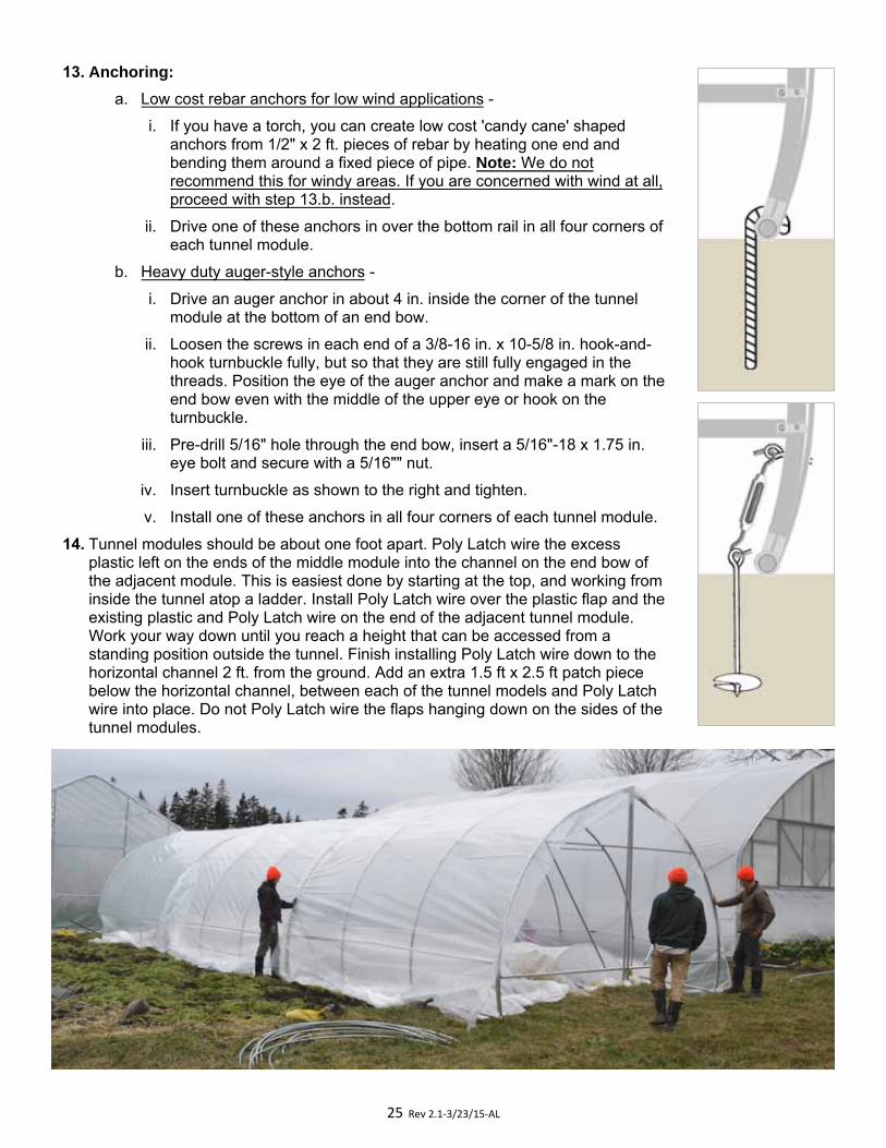
13. Anchoring:
a. Low cost rebar anchors for low wind applications -
i. If you have a torch, you can create low cost 'candy cane' shaped anchors from 1/2" x 2 ft. pieces of rebar by heating one end and bending them around a fixed piece of pipe. Note: We do not recommend this for windy areas. If you are concerned with wind at all, proceed with step 13.b. instead.
ii. Drive one of these anchors in over the bottom rail in all four corners of each tunnel module.
b. Heavy duty auger-style anchors -
i. Drive an auger anchor in about 4 in. inside the corner of the tunnel module at the bottom of an end bow.
ii. Loosen the screws in each end of a 3/8-16 in. x 10-5/8 in. hook-and-hook turnbuckle fully, but so that they are still fully engaged in the threads. Position the eye of the auger anchor and make a mark on the end bow even with the middle of the upper eye or hook on the turnbuckle.
iii. Pre-drill 5/16" hole through the end bow, insert a 5/16"-18 x 1.75 in. eye bolt and secure with a 5/16"" nut.
iv. Insert turnbuckle as shown to the right and tighten.
v. Install one of these anchors in all four corners of each tunnel module.
14. Tunnel modules should be about one foot apart. Poly Latch wire the excess plastic left on the ends of the middle module into the channel on the end bow of the adjacent module. This is easiest done by starting at the top, and working from inside the tunnel atop a ladder. Install Poly Latch wire over the plastic flap and the existing plastic and Poly Latch wire on the end of the adjacent tunnel module. Work your way down until you reach a height that can be accessed from a standing position outside the tunnel. Finish installing Poly Latch wire down to the horizontal channel 2 ft. from the ground. Add an extra 1.5 ft x 2.5 ft patch piece below the horizontal channel, between each of the tunnel models and Poly Latch wire into place. Do not Poly Latch wire the flaps hanging down on the sides of the tunnel modules.
26 Rev 2.1‐3/23/15‐AL
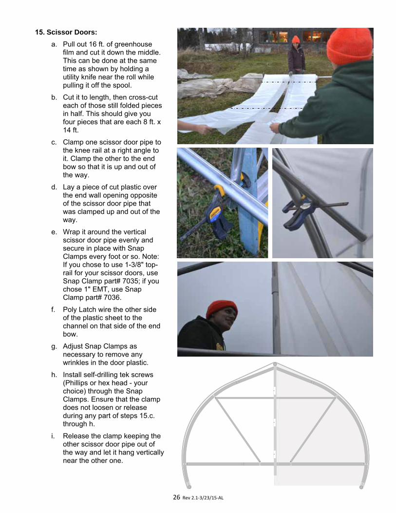
15. Scissor Doors:
a. Pull out 16 ft. of greenhouse film and cut it down the middle. This can be done at the same time as shown by holding a utility knife near the roll while pulling it off the spool.
b. Cut it to length, then cross-cut each of those still folded pieces in half. This should give you four pieces that are each 8 ft. x 14 ft.
c. Clamp one scissor door pipe to the knee rail at a right angle to it. Clamp the other to the end bow so that it is up and out of the way.
d. Lay a piece of cut plastic over the end wall opening opposite of the scissor door pipe that was clamped up and out of the way.
e. Wrap it around the vertical scissor door pipe evenly and secure in place with Snap Clamps every foot or so. Note: If you chose to use 1-3/8" top-rail for your scissor doors, use Snap Clamp part# 7035; if you chose 1" EMT, use Snap Clamp part# 7036.
f. Poly Latch wire the other side of the plastic sheet to the channel on that side of the end bow.
g. Adjust Snap Clamps as necessary to remove any wrinkles in the door plastic.
h. Install self-drilling tek screws (Phillips or hex head - your choice) through the Snap Clamps. Ensure that the clamp does not loosen or release during any part of steps 15.c. through h.
i. Release the clamp keeping the other scissor door pipe out of the way and let it hang vertically near the other one.
27 Rev 2.1‐3/23/15‐AL
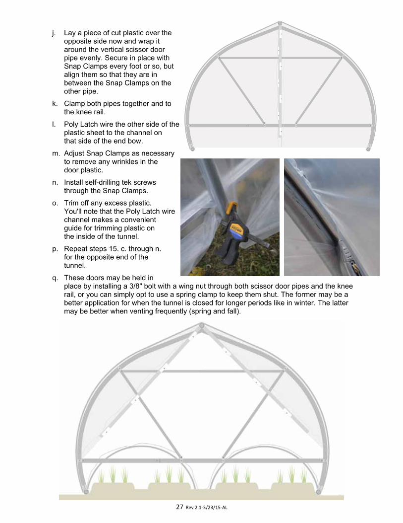
j. Lay a piece of cut plastic over theopposite side now and wrap itaround the vertical scissor doorpipe evenly. Secure in place withSnap Clamps every foot or so, butalign them so that they are inbetween the Snap Clamps on theother pipe.
k. Clamp both pipes together and tothe knee rail.
l. Poly Latch wire the other side of theplastic sheet to the channel onthat side of the end bow.
m. Adjust Snap Clamps as necessaryto remove any wrinkles in thedoor plastic.
n. Install self-drilling tek screwsthrough the Snap Clamps.
o. Trim off any excess plastic.You'll note that the Poly Latch wirechannel makes a convenientguide for trimming plastic onthe inside of the tunnel.
p. Repeat steps 15. c. through n.for the opposite end of thetunnel.
q. These doors may be held inplace by installing a 3/8" bolt with a wing nut through both scissor door pipes and the knee rail, or you can simply opt to use a spring clamp to keep them shut. The former may be a better application for when the tunnel is closed for longer periods like in winter. The latter may be better when venting frequently (spring and fall).
28 Rev 2.1‐3/23/15‐AL
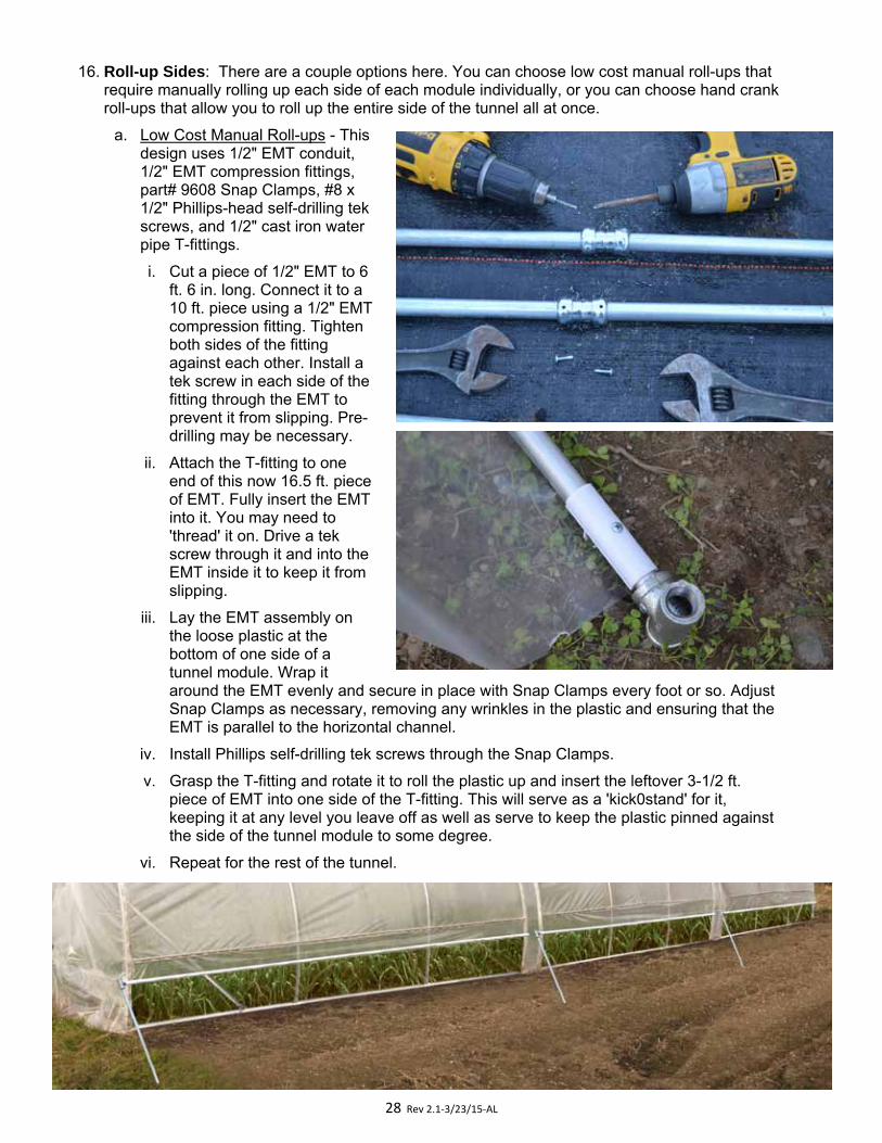
16. Roll-up Sides: There are a couple options here. You can choose low cost manual roll-ups that require manually rolling up each side of each module individually, or you can choose hand crank roll-ups that allow you to roll up the entire side of the tunnel all at once.
a. Low Cost Manual Roll-ups - This design uses 1/2" EMT conduit, 1/2" EMT compression fittings, part# 9608 Snap Clamps, #8 x 1/2" Phillips-head self-drilling tek screws, and 1/2" cast iron water pipe T-fittings.
i. Cut a piece of 1/2" EMT to 6 ft. 6 in. long. Connect it to a 10 ft. piece using a 1/2" EMT compression fitting. Tighten both sides of the fitting against each other. Install a tek screw in each side of the fitting through the EMT to prevent it from slipping. Pre-drilling may be necessary.
ii. Attach the T-fitting to one end of this now 16.5 ft. piece of EMT. Fully insert the EMT into it. You may need to 'thread' it on. Drive a tek screw through it and into the EMT inside it to keep it from slipping.
iii. Lay the EMT assembly on the loose plastic at the bottom of one side of a tunnel module. Wrap it around the EMT evenly and secure in place with Snap Clamps every foot or so. Adjust Snap Clamps as necessary, removing any wrinkles in the plastic and ensuring that the EMT is parallel to the horizontal channel.
iv. Install Phillips self-drilling tek screws through the Snap Clamps.
v. Grasp the T-fitting and rotate it to roll the plastic up and insert the leftover 3-1/2 ft. piece of EMT into one side of the T-fitting. This will serve as a 'kick0stand' for it, keeping it at any level you leave off as well as serve to keep the plastic pinned against the side of the tunnel module to some degree.
vi. Repeat for the rest of the tunnel.
29 Rev 2.1‐3/23/15‐AL
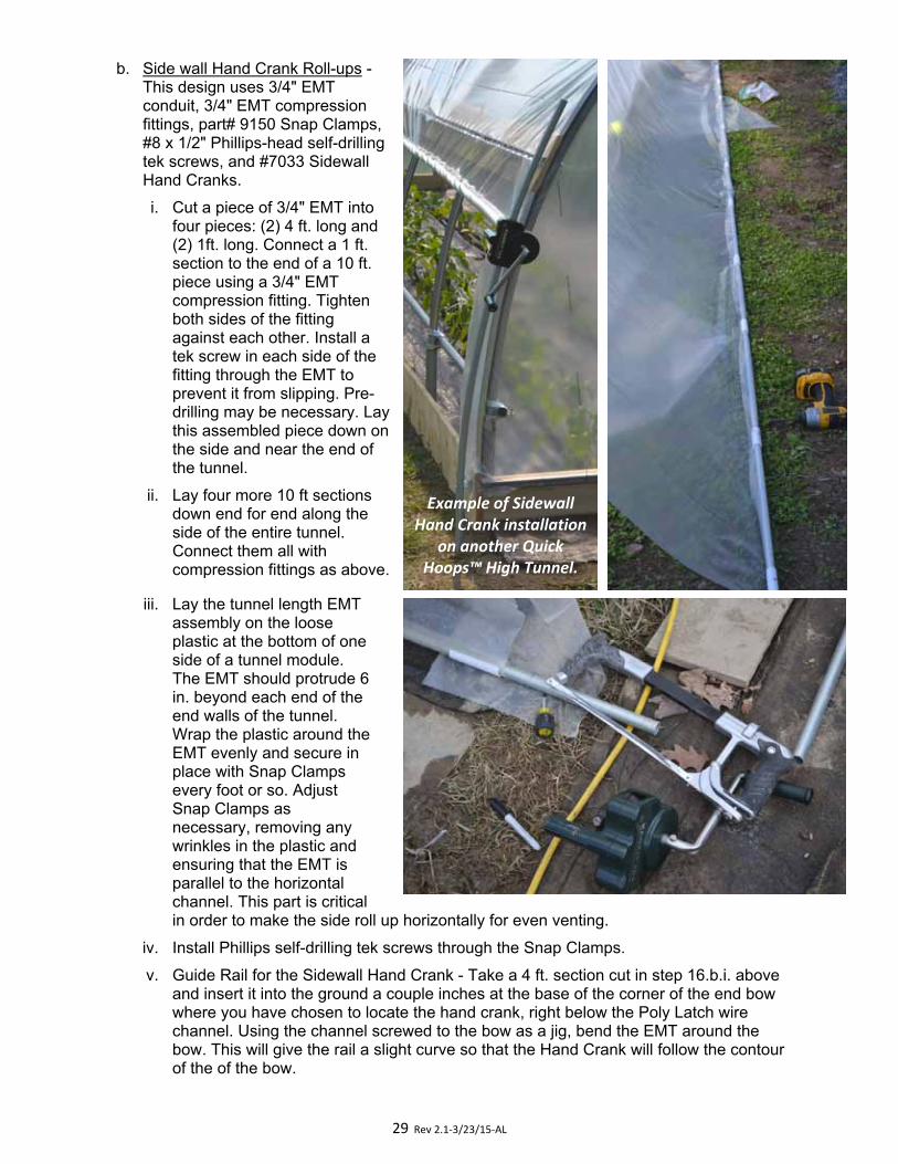
b. Side wall Hand Crank Roll-ups -This design uses 3/4" EMTconduit, 3/4" EMT compressionfittings, part# 9150 Snap Clamps,#8 x 1/2" Phillips-head self-drillingtek screws, and #7033 SidewallHand Cranks.
i. Cut a piece of 3/4" EMT intofour pieces: (2) 4 ft. long and(2) 1ft. long. Connect a 1 ft.section to the end of a 10 ft.piece using a 3/4" EMTcompression fitting. Tightenboth sides of the fittingagainst each other. Install atek screw in each side of thefitting through the EMT toprevent it from slipping. Pre-drilling may be necessary. Laythis assembled piece down onthe side and near the end ofthe tunnel.
ii. Lay four more 10 ft sectionsdown end for end along the side of the entire tunnel. Connect them all with compression fittings as above.
iii. Lay the tunnel length EMTassembly on the looseplastic at the bottom of oneside of a tunnel module.The EMT should protrude 6in. beyond each end of theend walls of the tunnel.Wrap the plastic around theEMT evenly and secure inplace with Snap Clampsevery foot or so. AdjustSnap Clamps asnecessary, removing anywrinkles in the plastic andensuring that the EMT isparallel to the horizontalchannel. This part is criticalin order to make the side roll up horizontally for even venting.
iv. Install Phillips self-drilling tek screws through the Snap Clamps.
v. Guide Rail for the Sidewall Hand Crank - Take a 4 ft. section cut in step 16.b.i. above and insert it into the ground a couple inches at the base of the corner of the end bow where you have chosen to locate the hand crank, right below the Poly Latch wire channel. Using the channel screwed to the bow as a jig, bend the EMT around the bow. This will give the rail a slight curve so that the Hand Crank will follow the contour of the of the bow.
Example of Sidewall Hand Crank installation
on another Quick Hoops™ High Tunnel.
30 Rev 2.1‐3/23/15‐AL
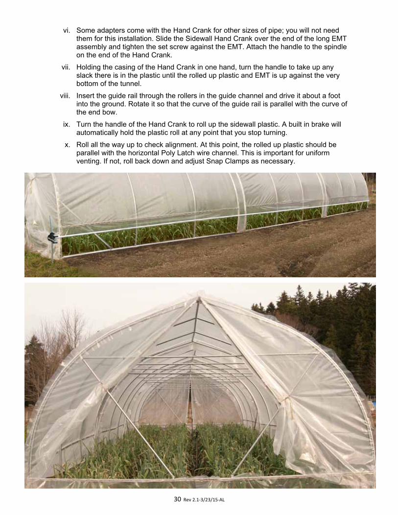
vi. Some adapters come with the Hand Crank for other sizes of pipe; you will not needthem for this installation. Slide the Sidewall Hand Crank over the end of the long EMTassembly and tighten the set screw against the EMT. Attach the handle to the spindleon the end of the Hand Crank.
vii. Holding the casing of the Hand Crank in one hand, turn the handle to take up anyslack there is in the plastic until the rolled up plastic and EMT is up against the verybottom of the tunnel.
viii. Insert the guide rail through the rollers in the guide channel and drive it about a footinto the ground. Rotate it so that the curve of the guide rail is parallel with the curve ofthe end bow.
ix. Turn the handle of the Hand Crank to roll up the sidewall plastic. A built in brake willautomatically hold the plastic roll at any point that you stop turning.
x. Roll all the way up to check alignment. At this point, the rolled up plastic should beparallel with the horizontal Poly Latch wire channel. This is important for uniformventing. If not, roll back down and adjust Snap Clamps as necessary.