Embed Size (px)
Citation preview
Fax and Modem Services over IP Overview
Last Updated: December 4, 2012
This application guide includes descriptions and configuration instructions for fax and modem transmissioncapabilities on Cisco Voice over IP (VoIP) networks. It is written for developers and networkadministrators who are installing, configuring, and maintaining fax and modem applications on Cisco voicegateways.
Note For more information about Cisco IOS voice features, see the entire Cisco IOS Voice ConfigurationLibrary ; including library preface and glossary, feature documents, and troubleshooting information.
• Finding Feature Information, page 1• Information About Cisco IOS Fax Services over IP, page 2• Information About Cisco IOS Modem Services over IP, page 19• Additional References, page 23• Related Documents, page 23• Standards, page 24• MIBs, page 25• RFCs, page 26• Technical Assistance, page 28
Finding Feature InformationYour software release may not support all the features documented in this module. For the latest caveatsand feature information, see Bug Search Tool and the release notes for your platform and software release.To find information about the features documented in this module, and to see a list of the releases in whicheach feature is supported, see the feature information table at the end of this module.
Use Cisco Feature Navigator to find information about platform support and Cisco software image support.To access Cisco Feature Navigator, go to www.cisco.com/go/cfn. An account on Cisco.com is not required.
Americas Headquarters:Cisco Systems, Inc., 170 West Tasman Drive, San Jose, CA 95134-1706 USA
Information About Cisco IOS Fax Services over IP• Fax Transmission in the PSTN, page 2• Fax Transmission over IP Networks, page 5• Cisco Fax Services, page 6
Fax Transmission in the PSTNFacsimile (fax) transmission is the sending of an image, drawing, or document over a distance byconverting it into coded electrical signals at the originating end, passing the signals from the originator tothe receiver over a transmission medium, and converting the signals into a replica of the original at thereceiving end.
When sending a fax, a fax machine uses a scanner to convert the paper image into digital bits, a single-chipmicroprocessor called a digital signal processor (DSP) to reduce the number of bits, and a modem toconvert the bits into an analog signal for transmission over an analog dial-up phone line.
When receiving a fax, the fax machine uses its modem and printer to convert the incoming bits into blackand white images on paper.
The information conveyed in a fax transmission consists of both protocol (control information, capabilities,identification) and document content . The document content consists primarily of the document image plusadditional metadata that accompanies the image. The means by which an image of a document is encodedwithin the fax content is the image data representation .
When a fax has been sent successfully, the sender receives a confirmation that indicates that the fax contentwas delivered. This confirmation is an internal signal and is not normally visible to the sending user,although some error messages are visible to allow a page to be resent.
The ability to send the representation of a page to a remote location developed over a number of years. Thefirst images were sent over wires as early as 1843, but modern fax machines did not start appearing inoffices until the 1960s. At that time, a single-page letter took about six minutes to send over public phonelines using the new Group 1 standard for transmission that was introduced by the International Telegraphand Telephone Consultative Committee (CCITT) in 1968. The Group 2 standard, introduced in 1976,reduced the time to send a page to three minutes, but still could not provide transmission at a dense enoughresolution for the clear reproduction of small print. In 1980, the Group 3 standard was introduced. TheGroup 3 standard improved fax scanning resolution and introduced digital transmission techniques toenable transmission rates of 14400 bits per second (bps). Group 3 fax machines are the most common todayby far. Group 4 is a standard for digital phone lines such as ISDN, and it operates at 64 kbps. Each standardspecifies special tones that identify calls as fax calls and enable handshaking to define fax capabilities atboth ends of the call. All of the fax standards have evolved with a goal of sending more data faster over thepublic switched telephone network (PSTN).
The PSTN is composed of switched time-division multiplexing (TDM) circuits, which are either singlelines or trunks. A line connects a single telephony device to a switch, whereas a trunk connects a switch toa switch. The network provides exclusive and full use of a circuit between two endpoints and is full-duplex(simultaneous transmission in both directions), unless the call is data. Trunks are one of the followingtypes:
• Analog trunks, in which nearly all the audio is sent as an analog signal.• Digital trunks that carry bit streams encoded by the G.711 codec and sent at 64 kbps. The bit streams
are also called pulse code modulation (PCM) streams.
Fax Transmission in the PSTN Information About Cisco IOS Fax Services over IP
2
Both circuit types have sufficient audio clarity, or dynamic range, to pass the tones required to send faxtraffic across PSTN circuits.
Fax traffic consists of digital data modulated onto high-frequency carrier tones. There are various ways tomodulate this information, such as Amplitude Modulation (AM), Frequency Modulation (FM) orFrequency Shift Keying (FSK), and Phase Modulation (PM) or Phase Shift Keying (PSK). In order to gethigher bit rates (more information) across the same carrier circuit, these modulation techniques are oftencombined into forms of modulation called Quadrature Amplitude Modulation (QAM) or Trellis-Codedmodulation.
• Data Transmission Standards, page 3• Fax Transmission Phases, page 3
Data Transmission StandardsThe international standards that define data transmission techniques are used by both fax and modemtransmission devices. The main difference between them is that modem payload originates as digital data,whereas fax payload is a paper image that has been encoded into a digital data stream. Another keydifference is the initial handshaking that determines the facsimile or data capabilities of each party in thetransmission.
There are standards that apply to both fax and modem machines and standards that apply to only faxmachines, defining methods by which faxes are encoded and sent.
The traditional facsimile transmission standard, also called Group 3 (G3) fax, describes implementations ofITU-T T.30 and T.4. All Cisco IOS fax applications use T.30 and T.4 standards to interface with the PSTNor fax device.
For a comprehensive list of fax and modem standards, see the Standards, page 24,
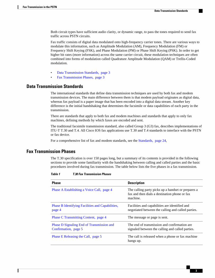
Fax Transmission PhasesThe T.30 specification is over 150 pages long, but a summary of its contents is provided in the followingsections to provide some familiarity with the handshaking between calling and called parties and the basicprocedures involved during fax transmission. The table below lists the five phases in a fax transmission.
Table 1 T.30 Fax Transmission Phases
Phase Description
Phase A Establishing a Voice Call, page 4 The calling party picks up a handset or prepares afax and then dials a destination phone or faxmachine.
Phase B Identifying Facilities and Capabilities, page 4
Facilities and capabilities are identified andnegotiated between the calling and called parties.
Phase C Transmitting Content, page 4 The message or page is sent.
Phase D Signaling End of Transmission andConfirmation, page 5
The end of transmission and confirmation aresignaled between the calling and called parties.
Phase E Releasing the Call, page 5 The call is released when a phone or fax machinehangs up.
Fax Transmission in the PSTNData Transmission Standards
3
• Phase A Establishing a Voice Call, page 4• Phase B Identifying Facilities and Capabilities, page 4• Phase C Transmitting Content, page 4• Phase D Signaling End of Transmission and Confirmation, page 5• Phase E Releasing the Call, page 5
Phase A Establishing a Voice Call
The call originator prepares a fax and dials a destination number. The destination fax device picks up thecall. The originator and the destination are now connected in a voice call, but to transition to faxtransmission one party must signal that it is a fax device. Either device can send its signal first, using one ofthe following methods:
• The calling device sends a Calling Tone (CNG) to the destination device. The CNG identifies thecalling device as a fax machine. The CNG is a repeating 1100-Hz tone that is on for 0.5 seconds andthen off for 3 seconds.
• The called device sends a Called Station Identifier (CED) tone, which identifies the called device as afax machine. CED is a 2100-Hz tone that is on for 2.6 to 4 seconds.
Once these messages have been exchanged, the transaction can move to phase B.
Phase B Identifying Facilities and Capabilities
The following sequence of events identifies facilities and capabilities for fax transmission:
1 The called device sends a Digital Information Signal (DIS), which describes the called fax machine’sreception facilities, such as maximum page length, scan line time, image resolution, and error correctionmode. Many standard facilities are contained in the DIS message, and they are defined in the T.30specification.
2 The calling device examines the DIS message and in response sends a Digital Command Signal (DCS)that tells the called device which facilities to select for the reception of the fax transmission.
3 The called device may also choose to send the following optional messages:4 Called Subscriber Identification (CSI) provides some detail as to the identity of the called device.5 Non-Standard Facilities (NSF) informs the calling device that the called device may have some extra
features that can be utilized during the fax transmission.6 The calling device can then choose to send a Transmitting Subscriber Identification (TSI) message.
Also, in response to an NSF message, the calling device can send a Non-Standard facilities Setup (NSS)message to select extra reception parameters on the called device.
7 The calling device now sends the Training Check (TCF) message, which includes a stream of 0s forabout 1.5 seconds through the HS modulation that was agreed upon during the DIS-DCS handshake.The called device then responds with a Failure To Train (FTT) if the modulation speed is not acceptableor with a Confirmation to Receive (CFR) if the modulation speed is acceptable. Training is a processthat verifies the communication path.
8 Once the training has been completed and the modulation speed is agreed upon, the fax devices move tophase C and start the transmission of T.4 page data using HS modulation.
Phase C Transmitting Content
Phase C is referred to as the In-message Procedure. During this phase, high-speed T.4 page data is sent oneline at a time. Each burst of line data is followed by an End Of Line (EOL) message. Because the EOLinformation is sent as T.4 data, it would not necessarily be seen in a T.30 trace. When the sending devicehas finished sending pages or wishes to return back to control mode, it sends 6 EOLs in a series that
Fax Transmission in the PSTN Phase A Establishing a Voice Call
4
constitutes a Return To Control (RTC) message. The RTC message indicates the end of phase C, and thecall progresses to phase D.
Note If the fax machines decide during phase B to use Error Correction Mode (ECM), the format of the data sentduring phase C may be different. With ECM, the T.4 page data is grouped into high-level data link control(HDLC) frames rather than being sent in a raw stream. This means that if the HDLC blocks of T.4 pagedata are not received error-free, a Partial Page Request (PPR) message can be sent, listing the frames thatwere not received and asking for them to be resent. The details of the transmission differences during phaseC with ECM enabled are explained in Annex A of the T.30 specification.
Phase D Signaling End of Transmission and ConfirmationAfter the T.4 transmission and the subsequent return to control mode, the sending device must send one ofthe following signals:
• Partial Page Signal (PPS)--Devices that send faxes with ECM can send a PPS, which must beacknowledged by a Message Confirmation (MCF) signal from the receiving device.
• End Of Procedure (EOP)--This signal indicates that transmission of pages is complete and that thereare no more pages to send. The EOP must be acknowledged with an MCF from the receiving device,after which the devices can move to phase E.
Phase E Releasing the CallFollowing the fax transmission and the postmessage transactions, either the calling device or the calleddevice can send a Disconnect (DCN) message, at which point the devices tear down the call, and thetelephony call control layer releases the circuit. DCN messages do not require a response from the oppositedevice.
Fax Transmission over IP NetworksAn IP, or packet-switched, network enables data to be sent in packets to remote locations. The data isassembled by a packet assembler/disassembler (PAD) into individual packets of data, involving a processof segmentation or subdivision of larger sets of data as specified by the native protocol of the sendingdevice. Each packet has a unique identifier that makes it independent and has its own destination address.Because the packet is unique and independent, it can traverse the network in a stream of packets and usedifferent routes. This fact has some implications for fax transmissions that use data packets rather thanusing an analog signal over a circuit-switched network.
• Differences from Fax Transmission in the PSTN, page 5• Fax Services over IP Networks, page 6
Differences from Fax Transmission in the PSTNIndividual packets that are part of the same data transmission may follow different physical paths ofvarying lengths. They can also experience varying levels of propagation delay (latency) and delay that iscaused by being held in packet buffers awaiting the availability of a subsequent circuit. The packets canalso arrive in an order different from the order in which they entered the network. The destination node ofthe network uses the identifiers and addresses in the packet sequencing information to reassemble thepackets into the correct sequence.
Fax transmissions are designed to operate across a 64-kbps, PCM-encoded voice circuit, but in packetnetworks the 64-kbps stream is often compressed into a much smaller data rate by passing it through a
Fax Transmission over IP NetworksPhase D Signaling End of Transmission and Confirmation
5

digital signal processor (DSP). The codecs normally used to compress a voice stream in DSPs are designedto compress and decompress human speech, not fax or modem tones. For this reason, faxes and modemsare rarely used in a VoIP network without some kind of relay or pass-through mechanism in place.
Fax Services over IP NetworksThere are two conceptual methods of carrying virtually real-time fax-machine-to-fax-machinecommunication across packet networks:
• Fax relay, in which the T.30 fax from the PSTN is demodulated at the sending gateway. Thedemodulated fax content is enveloped into packets, sent over the network, and remodulated into T.30fax at the receiving end.
• Fax pass-through, in which modulated fax information from the PSTN is passed in-band end-to-endover a voice speech path in an IP network. The following two pass-through techniques are possible:
◦ The configured voice codec is used for the fax transmission. This technique works only when theconfigured codec is G.711 with no voice activity detection (VAD) and no echo cancellation (EC),or when the configured codec is a clear-channel codec or G.726/32. Low bit-rate codecs cannot beused for fax transmissions.
◦ The gateway dynamically changes the codec from the codec configured for voice to G.711 withno VAD and no EC for the duration of the fax session. This method is specifically referred to ascodec upspeed or fax pass-through with upspeed.
In addition to the methods for real-time fax transmission, a method called store-and-forward fax breaks thefax process into distinct sending and receiving processes and allows fax messages to be stored betweenthose processes. store-and-forward fax is based on the ITU-T T.37 standard, and it also enables faxtransmissions to be received from or delivered to computers rather than fax machines.
Cisco Fax ServicesSome of the methods described in this section have different characteristics depending on the call controlprotocol used by the network, which may be H.323, Session Initiation Protocol (SIP), or Media GatewayControl Protocol (MGCP). Where the characteristics are different, they are noted.
Finding Support Information for Platforms and Cisco IOS Software Images
Use Cisco Feature Navigator to find information about platform support and Cisco IOS software imagesupport. Access Cisco Feature Navigator at http://www.cisco.com/go/fn . You must have an account onCisco.com. If you do not have an account or have forgotten your username or password, click Cancel at thelogin dialog box and follow the instructions that appear.
This section describes the following aspects of the fax services available on Cisco IOS gateways:
• Concepts Related to Cisco Fax Services, page 6• Fax Pass-Through and Fax Pass-Through with Upspeed, page 9• Cisco Fax Relay, page 11• T.38 Fax Relay, page 13• T.37 Store-and-Forward Fax, page 16• IVR Applications for Fax, page 18
Concepts Related to Cisco Fax Services
Cisco Fax Services Fax Services over IP Networks
6
The following concepts are useful in understanding how fax transmission methods are implemented onCisco IP networks:
• Voice Gateways and Dial Peers, page 7• TCL IVR, page 8• QoS, page 8
Voice Gateways and Dial Peers
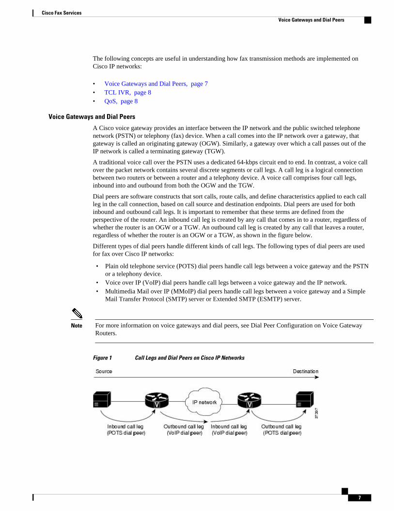
A Cisco voice gateway provides an interface between the IP network and the public switched telephonenetwork (PSTN) or telephony (fax) device. When a call comes into the IP network over a gateway, thatgateway is called an originating gateway (OGW). Similarly, a gateway over which a call passes out of theIP network is called a terminating gateway (TGW).
A traditional voice call over the PSTN uses a dedicated 64-kbps circuit end to end. In contrast, a voice callover the packet network contains several discrete segments or call legs. A call leg is a logical connectionbetween two routers or between a router and a telephony device. A voice call comprises four call legs,inbound into and outbound from both the OGW and the TGW.
Dial peers are software constructs that sort calls, route calls, and define characteristics applied to each callleg in the call connection, based on call source and destination endpoints. Dial peers are used for bothinbound and outbound call legs. It is important to remember that these terms are defined from theperspective of the router. An inbound call leg is created by any call that comes in to a router, regardless ofwhether the router is an OGW or a TGW. An outbound call leg is created by any call that leaves a router,regardless of whether the router is an OGW or a TGW, as shown in the figure below.
Different types of dial peers handle different kinds of call legs. The following types of dial peers are usedfor fax over Cisco IP networks:
• Plain old telephone service (POTS) dial peers handle call legs between a voice gateway and the PSTNor a telephony device.
• Voice over IP (VoIP) dial peers handle call legs between a voice gateway and the IP network.• Multimedia Mail over IP (MMoIP) dial peers handle call legs between a voice gateway and a Simple
Mail Transfer Protocol (SMTP) server or Extended SMTP (ESMTP) server.
Note For more information on voice gateways and dial peers, see Dial Peer Configuration on Voice GatewayRouters.
Figure 1 Call Legs and Dial Peers on Cisco IP Networks
Cisco Fax ServicesVoice Gateways and Dial Peers
7
TCL IVR
Tool Command Language (TCL) is used for scripts that direct interactive voice response (IVR)applications, which are used in Cisco voice networks for various purposes. IVR applications typicallyinvolve the real-time gathering of data from callers by means of digit collection and voice prompts. Forexample, you might have a debit card application that asks a user to enter a personal identification number(PIN) and then collects and verifies the digits that the user enters.
A gateway can have several IVR applications to accommodate different gateway services, and you cancustomize IVR applications to present different interfaces to various callers. IVR applications are used toimplement the following fax services:
• T.37 Store-and-Forward Fax, page 16• Fax Detection IVR Application, page 18• Fax Rollover IVR Application, page 19
TCL scripts are provided on the Cisco Software Center website. You download them to a location that isaccessible to the voice gateway that is running the fax application and then configure the gateway with thename and location of the script.
Note For more information on TCL IVR, see the Cisco IOS TCL and VoiceXML Application Guide .
QoS
Quality of service (QoS) refers to the ability of a network--whether the network is a complex network,small corporate network, Internet service provider (ISP), or enterprise network--to provide better service toselected network traffic over various technologies, including Frame Relay, ATM, Ethernet and 802.1networks, and SONET, as well as IP-routed networks that may use any or all of these underlyingtechnologies.
The primary goals of QoS are to provide better and more predictable network service by providingdedicated bandwidth, controlled jitter and latency, and improved loss characteristics. QoS achieves thesegoals by providing tools for managing network congestion, shaping network traffic, using expensive wide-area links more efficiently, and setting traffic policies across the network.
QoS for fax transmissions means assuring that echo cancellation (EC) and voice activity detection (VAD),which are normally enabled for voice calls, are turned off as soon as a call is identified as a fax call. If ECand VAD are enabled, they can interfere with the successful reception of fax traffic.
The advantages of carrying fax over packet networks are reduced cost and saved bandwidth and areassociated with QoS issues that are unique to packet networks. A major issue in the implementation of faxover IP networks is the problem of inaccurate timing of messages caused by delay through the network.
The delay of fax packets through a packet network causes the precise timing that is required for manyportions of the fax protocol to be skewed and can result in the loss of the call. The fax-over-packet protocolin the interworking function must compensate for the loss of a fixed timing of messages over the packetnetwork so that the T.30 protocol operates without error. Error Correction Mode (ECM) is enabled in the T.30 protocol.
An end-to-end fax over IP call is susceptible to the following sources of delay:
• Network delay--Network delay is caused by the physical medium and protocols that are used to sendfax data and by buffers that are used to remove packet jitter on the receiving end. This delay is afunction of the capacity of the links in the network and the processing that occurs as the packets transit
Cisco Fax Services TCL IVR
8
the network. The jitter buffers add delay when they remove the packet delay variation of each packetas it transits the packet network. This delay can be a significant part of the overall delay becausepacket delay variations can be as high as 70 to 100 milliseconds in some Frame Relay networks, andeven higher in IP networks.
• Processing delay--Processing delay is caused by the process of demodulating and collecting digital faxinformation into a packet for transmission over the packet network. Encoding delay, which is one typeof processing delay, is a function of both the processor execution time and the amount of datacollected before a packet is sent to the network.
Delay issues are compounded by the need to remove jitter, which is the variable interpacket arrival timethat is caused by conditions in the network that a packet traverses. An approach to removing the jitter is tocollect packets and hold them long enough so that even the slowest packets arrive in time to be played inthe correct sequence. This approach, however, causes additional delay. In most fax over IP methods, a timestamp is incorporated in the packet to ensure that packet data is played out at the proper instant.
The T.30 standard provides for ECM that allows a fax page to be broken into HDLC-like frames that allowtransmission errors to be detected. ECM works by sending a fax page in a series of blocks. After receivingthe complete page data, the receiving fax identifies any frames with errors. The sending fax thenretransmits those frames. This process is repeated until all frames have been received without errors.
If a receiving fax machine is not able to receive an error-free page, the fax transmission may fail, and oneof the fax machines may disconnect. If a network has packet-loss levels greater than 3 to 5 percent, faxtransmissions consistently fail when ECM is enabled. Fax relay packet loss concealment disables ECM sothat fax calls with up to 9 percent packet loss succeed and calls with packet loss of 5 to 7 percent succeedwith acceptable quality.
For more information, see the following documents:
• QoS: Quality of Service for Voice.• Fax relay packet loss concealment: Chapter 1, "Configuring Cisco Fax Relay" or Chapter 1,
"Configuring T.38 Fax Relay."
Fax Pass-Through and Fax Pass-Through with UpspeedFax pass-through is the simplest technique for sending fax over IP networks, but it is not the default, nor isit the most desirable method of supporting fax over IP. T.38 fax relay provides a more reliable and error-free method of sending faxes over an IP network, but some third-party H.323 and SIP implementations donot support T.38 fax relay. These same implementations often support fax pass-through.
Fax pass-through is the state of the channel after the fax upspeed process has occurred. In fax pass-throughmode, gateways do not distinguish a fax call from a voice call. Fax communication between the two faxmachines is carried in its entirety in-band over a voice call. When using fax pass-through with upspeed, thegateways are to some extent aware of the fax call. Although relay mechanisms are not employed, withupspeed the gateways do recognize a CED fax tone and automatically change the voice codec to G.711 ifnecessary (thus the designation upspeed ) and turn off echo cancellation (EC) and voice activity detection(VAD) for the duration of the call.
Fax pass-through is also known as Voice Band Data (VBD) by the International Telecommunication Union(ITU). VBD refers to the transport of fax or modem signals over a voice channel through a packet networkwith an encoding appropriate for fax or modem signals. The minimum set of coders for VBD mode is G.711 u-law and a-law with VAD disabled.
Once a terminating gateway (TGW) detects a CED tone from a called fax machine, the TGW exchangesthe voice codec that was negotiated during the voice call setup for a G.711 codec and turns off EC andVAD. This switchover is communicated to the originating gateway (OGW), which allows the fax machinesto transfer modem signals as though they were traversing the PSTN. If the voice codec that was configured
Cisco Fax ServicesFax Pass-Through and Fax Pass-Through with Upspeed
9
and negotiated for the VoIP call is G.711 when the CED tone is detected, there is no need to make anychanges to the session other than turning off EC and VAD.
Before pass-through features were introduced (in Cisco IOS Release 12.1(3)T for the Cisco AS5300, andlater for other Cisco IOS gateway platforms), fax pass-through was achieved by manually configuring adial peer that only matched fax calls to set the codec parameters to G.711 with no EC and no VAD (or toclear-channel codec). Control of fax pass-through is achieved through named signaling events (NSEs) thatare sent in the RTP stream.
NSEs are a Cisco-proprietary version of IETF-standard named telephony events (NTEs), which arespecially marked data packets used to digitally convey telephony signaling tones and events. NSEs usedifferent event values than NTEs and are generally sent with RTP payload type 100, whereas NTEs usepayload type 101. NSEs and NTEs provide a more reliable way to communicate tones and events by usinga single packet rather than a series of in-band packets that can be corrupted or partially lost.
Fax pass-through and fax pass-through with upspeed use peer-to-peer NSEs within the Real-TimeTransport Protocol (RTP) stream or bearer stream to coordinate codec switchover and the disabling of ECand VAD. Redundant packets can be sent to improve reliability when the probability of packet loss is high.
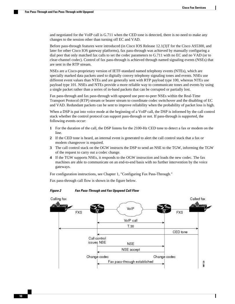
When a DSP is put into voice mode at the beginning of a VoIP call, the DSP is informed by the call controlstack whether the control protocol can support pass-through or not. If pass-through is supported, thefollowing events occur:
1 For the duration of the call, the DSP listens for the 2100-Hz CED tone to detect a fax or modem on theline.
2 If the CED tone is heard, an internal event is generated to alert the call control stack that a fax ormodem changeover is required.
3 The call control stack on the OGW instructs the DSP to send an NSE to the TGW, informing the TGWof the request to carry out a codec change.
4 If the TGW supports NSEs, it responds to the OGW instruction and loads the new codec. The faxmachines are able to communicate on an end-to-end basis with no further intervention by the voicegateways.
For configuration instructions, see Chapter 1, "Configuring Fax Pass-Through."
Fax pass-through call flow is shown in the figure below.
Figure 2 Fax Pass-Through and Fax Upspeed Call Flow
Cisco Fax Services Fax Pass-Through and Fax Pass-Through with Upspeed
10
Cisco Fax RelayCisco fax relay is the oldest method of supporting fax on Cisco IOS gateways and has been supported sinceCisco IOS Release 11.3. Cisco fax relay uses Real-Time Transport Protocol (RTP) as the method oftransport. In Cisco fax relay mode, gateways terminate T.30 fax signaling by spoofing a virtual fax machineto the locally attached fax machine. The gateways use a Cisco-proprietary fax-relay RTP-based protocol tocommunicate between them.
Unlike fax pass-through, fax relay demodulates the fax modem bits at the local gateway, sends theinformation across the voice network using the fax relay protocol, and then remodulates the bits back intotones at the far gateway. The fax machines on either end are sending and receiving tones and are not awarethat a demodulation/modulation fax relay process is occurring.
The default method for fax transmission on Cisco IOS gateways is Cisco fax relay. This is an RTP-basedtransmission method that uses proprietary signaling and encoding mechanisms. Cisco fax relay capability iswidely available and has been in the Cisco IOS gateway software since Cisco IOS Release 11.3, whichintroduced DSPs to enable voice applications. The mechanism for Cisco fax relay is the same for calls thatare controlled by SIP, MGCP, or H.323 call control protocols.
Before T.38 standards-based fax relay was introduced, no command-line interface (CLI) was required toenable Cisco fax relay. Today Cisco fax relay is still the default, but explicit CLI enables a choice betweenthe fax relay methods.
Cisco fax relay is the default operation and, in the absence of any explicit CLI on the dial peer, is usedwhen a fax transmission is detected. If voice calls are being completed successfully between two routers,fax calls should also work. Events that occur during a Cisco fax relay call fall into the following callphases:
For configuration information, see Chapter 1, "Configuring Cisco Fax Relay."
• Cisco Fax Relay Fax Setup Phase, page 11• Cisco Fax Relay Data Transfer Phase, page 12
Cisco Fax Relay Fax Setup Phase
When a DSP is put into voice mode at the beginning of a VoIP call, the DSP is informed by the call controlstack whether fax relay is supported and if it is supported, whether it is Cisco fax relay or T.38 fax relay. IfCisco fax relay is supported, the following events occur:
• Initially a VoIP call is established as if it were a normal speech call. Call control procedures arefollowed and the DSP is put into voice mode, after which human speech is expected to be received andprocessed.
• At any time during the life of the call, if a fax answer or calling tone (ANSam or CED) is heard, theDSP does not interfere with the speech processing. The ANSam or CED tone causes a switch tomodem passthrough, if enabled, to allow the tone to pass cleanly to the remote fax.
• A normal fax machine, after generating a CED or hearing a CNG, sends a DIS message with thecapabilities of the fax machine. The DSP in the Cisco IOS gateway attached to the fax machine thatgenerated the DIS message (normally the TGW) detects the HDLC flag sequence at the start of theDIS message and initiates fax relay switchover. The DSP also triggers an internal event to notify thecall control stack that fax switchover is required. The call control stack then instructs the DSP tochange the RTP payload type to 96 and to send this payload type to the OGW.
• When the DSP on the OGW receives an RTP packet with payload type set to 96, it triggers an event toinform its own call control stack that a fax changeover has been requested by the remote gateway. TheOGW then sends an RTP packet to the TGW with payload type 97 to indicate that the OGW has
Cisco Fax ServicesCisco Fax Relay
11
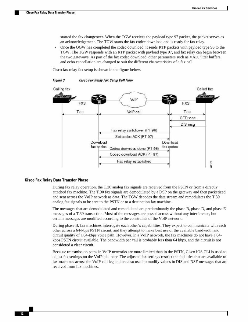
started the fax changeover. When the TGW receives the payload type 97 packet, the packet serves asan acknowledgement. The TGW starts the fax codec download and is ready for fax relay.
• Once the OGW has completed the codec download, it sends RTP packets with payload type 96 to theTGW. The TGW responds with an RTP packet with payload type 97, and fax relay can begin betweenthe two gateways. As part of the fax codec download, other parameters such as VAD, jitter buffers,and echo cancellation are changed to suit the different characteristics of a fax call.
Cisco fax relay fax setup is shown in the figure below.
Figure 3 Cisco Fax Relay Fax Setup Call Flow
Cisco Fax Relay Data Transfer Phase
During fax relay operation, the T.30 analog fax signals are received from the PSTN or from a directlyattached fax machine. The T.30 fax signals are demodulated by a DSP on the gateway and then packetizedand sent across the VoIP network as data. The TGW decodes the data stream and remodulates the T.30analog fax signals to be sent to the PSTN or to a destination fax machine.
The messages that are demodulated and remodulated are predominantly the phase B, phase D, and phase Emessages of a T.30 transaction. Most of the messages are passed across without any interference, butcertain messages are modified according to the constraints of the VoIP network.
During phase B, fax machines interrogate each other’s capabilities. They expect to communicate with eachother across a 64-kbps PSTN circuit, and they attempt to make best use of the available bandwidth andcircuit quality of a 64-kbps voice path. However, in a VoIP network, the fax machines do not have a 64-kbps PSTN circuit available. The bandwidth per call is probably less than 64 kbps, and the circuit is notconsidered a clear circuit.
Because transmission paths in VoIP networks are more limited than in the PSTN, Cisco IOS CLI is used toadjust fax settings on the VoIP dial peer. The adjusted fax settings restrict the facilities that are available tofax machines across the VoIP call leg and are also used to modify values in DIS and NSF messages that arereceived from fax machines.
Cisco Fax Services Cisco Fax Relay Data Transfer Phase
12
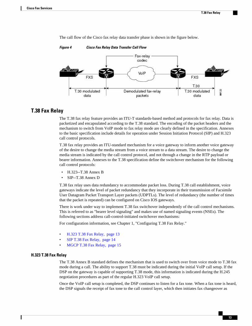
The call flow of the Cisco fax relay data transfer phase is shown in the figure below.
Figure 4 Cisco Fax Relay Data Transfer Call Flow
T.38 Fax RelayThe T.38 fax relay feature provides an ITU-T standards-based method and protocols for fax relay. Data ispacketized and encapsulated according to the T.38 standard. The encoding of the packet headers and themechanism to switch from VoIP mode to fax relay mode are clearly defined in the specification. Annexesto the basic specification include details for operation under Session Initiation Protocol (SIP) and H.323call control protocols.
T.38 fax relay provides an ITU-standard mechanism for a voice gateway to inform another voice gatewayof the desire to change the media stream from a voice stream to a data stream. The desire to change themedia stream is indicated by the call control protocol, and not through a change in the RTP payload orbearer information. Annexes to the T.38 specification define the switchover mechanism for the followingcall control protocols:
• H.323--T.38 Annex B• SIP--T.38 Annex D
T.38 fax relay uses data redundancy to accommodate packet loss. During T.38 call establishment, voicegateways indicate the level of packet redundancy that they incorporate in their transmission of FacsimileUser Datagram Packet Transport Layer packets (UDPTLs). The level of redundancy (the number of timesthat the packet is repeated) can be configured on Cisco IOS gateways.
There is work under way to implement T.38 fax switchover independently of the call control mechanisms.This is referred to as "bearer level signaling" and makes use of named signaling events (NSEs). Thefollowing sections address call-control-initiated switchover mechanisms:
For configuration information, see Chapter 1, "Configuring T.38 Fax Relay."
• H.323 T.38 Fax Relay, page 13• SIP T.38 Fax Relay, page 14• MGCP T.38 Fax Relay, page 15
H.323 T.38 Fax Relay
The T.38 Annex B standard defines the mechanism that is used to switch over from voice mode to T.38 faxmode during a call. The ability to support T.38 must be indicated during the initial VoIP call setup. If theDSP on the gateway is capable of supporting T.38 mode, this information is indicated during the H.245negotiation procedures as part of the regular H.323 VoIP call setup.
Once the VoIP call setup is completed, the DSP continues to listen for a fax tone. When a fax tone is heard,the DSP signals the receipt of fax tone to the call control layer, which then initiates fax changeover as
Cisco Fax ServicesT.38 Fax Relay
13
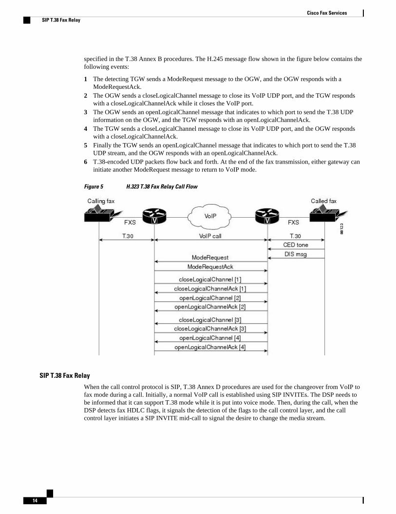
specified in the T.38 Annex B procedures. The H.245 message flow shown in the figure below contains thefollowing events:
1 The detecting TGW sends a ModeRequest message to the OGW, and the OGW responds with aModeRequestAck.
2 The OGW sends a closeLogicalChannel message to close its VoIP UDP port, and the TGW respondswith a closeLogicalChannelAck while it closes the VoIP port.
3 The OGW sends an openLogicalChannel message that indicates to which port to send the T.38 UDPinformation on the OGW, and the TGW responds with an openLogicalChannelAck.
4 The TGW sends a closeLogicalChannel message to close its VoIP UDP port, and the OGW respondswith a closeLogicalChannelAck.
5 Finally the TGW sends an openLogicalChannel message that indicates to which port to send the T.38UDP stream, and the OGW responds with an openLogicalChannelAck.
6 T.38-encoded UDP packets flow back and forth. At the end of the fax transmission, either gateway caninitiate another ModeRequest message to return to VoIP mode.
Figure 5 H.323 T.38 Fax Relay Call Flow
SIP T.38 Fax Relay
When the call control protocol is SIP, T.38 Annex D procedures are used for the changeover from VoIP tofax mode during a call. Initially, a normal VoIP call is established using SIP INVITEs. The DSP needs tobe informed that it can support T.38 mode while it is put into voice mode. Then, during the call, when theDSP detects fax HDLC flags, it signals the detection of the flags to the call control layer, and the callcontrol layer initiates a SIP INVITE mid-call to signal the desire to change the media stream.
Cisco Fax Services SIP T.38 Fax Relay
14
Note For initial INVITE in SIP calls, Cisco UBE and voice gateways do not support having both fax (T.38) andaudio capabilities together.
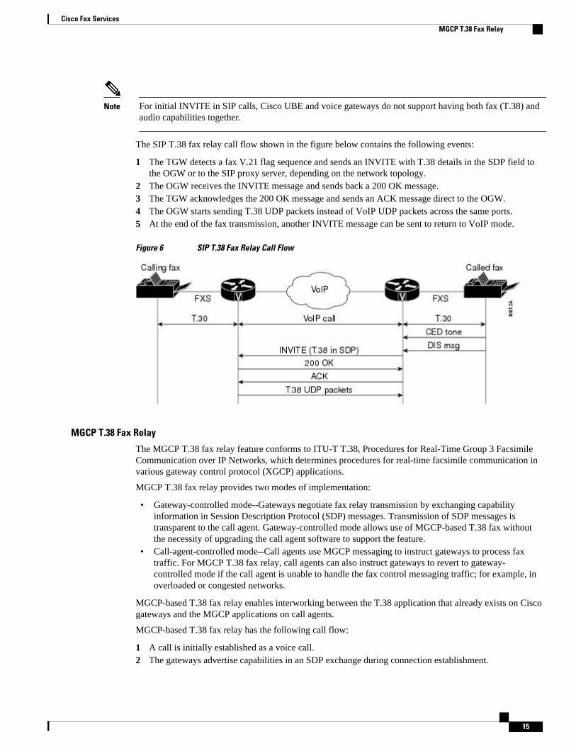
The SIP T.38 fax relay call flow shown in the figure below contains the following events:
1 The TGW detects a fax V.21 flag sequence and sends an INVITE with T.38 details in the SDP field tothe OGW or to the SIP proxy server, depending on the network topology.
2 The OGW receives the INVITE message and sends back a 200 OK message.3 The TGW acknowledges the 200 OK message and sends an ACK message direct to the OGW.4 The OGW starts sending T.38 UDP packets instead of VoIP UDP packets across the same ports.5 At the end of the fax transmission, another INVITE message can be sent to return to VoIP mode.
Figure 6 SIP T.38 Fax Relay Call Flow
MGCP T.38 Fax Relay
The MGCP T.38 fax relay feature conforms to ITU-T T.38, Procedures for Real-Time Group 3 FacsimileCommunication over IP Networks, which determines procedures for real-time facsimile communication invarious gateway control protocol (XGCP) applications.
MGCP T.38 fax relay provides two modes of implementation:
• Gateway-controlled mode--Gateways negotiate fax relay transmission by exchanging capabilityinformation in Session Description Protocol (SDP) messages. Transmission of SDP messages istransparent to the call agent. Gateway-controlled mode allows use of MGCP-based T.38 fax withoutthe necessity of upgrading the call agent software to support the feature.
• Call-agent-controlled mode--Call agents use MGCP messaging to instruct gateways to process faxtraffic. For MGCP T.38 fax relay, call agents can also instruct gateways to revert to gateway-controlled mode if the call agent is unable to handle the fax control messaging traffic; for example, inoverloaded or congested networks.
MGCP-based T.38 fax relay enables interworking between the T.38 application that already exists on Ciscogateways and the MGCP applications on call agents.
MGCP-based T.38 fax relay has the following call flow:
1 A call is initially established as a voice call.2 The gateways advertise capabilities in an SDP exchange during connection establishment.
Cisco Fax ServicesMGCP T.38 Fax Relay
15
3 If both gateways do not support T.38 fax relay, fax pass-through is used for fax transmission. If bothgateways support T.38, they attempt to switch to T.38 upon fax tone detection. The existing audiochannel is used for T.38 fax relay, and the existing connection port is reused to minimize delay. Iffailure occurs at some point during the switch to T.38, the call reverts to the original settings it had as avoice call. If this failure occurs, a fallback to fax pass-through is not supported.
4 Upon completion of the fax image transfer, the connection remains established and reverts to a voicecall using the previously designated codec, unless the call agent instructs the gateways to do otherwise.
A fax relay MGCP event allows the gateway to notify the call agent of the status (start, stop, or failure) ofT.38 processing for the connection. This event is sent in both call-agent-controlled and gateway-controlledmode.
Gateway-Controlled MGCP T.38 Fax Relay
In gateway-controlled mode, a call agent uses the fx: extension of the local connection option (LCO) toinstruct a gateway about how to process a call. Gateways do not need instruction from the call agent toswitch to T.38 mode. This mode is used if the call agent has not been upgraded to support T.38 and MGCPinterworking, or if the call agent does not want to manage fax calls. Gateway-controlled mode can also beused to bypass the message delay overhead caused by call agent handling; for example, to meet timerequirements for switchover to T.38 mode. If the call agent does not specify the mode to the gateway, thegateway defaults to gateway-controlled mode.
In gateway-controlled mode, the gateways exchange NSEs that do the following:
• Instruct the peer gateway to switch to T.38 for a fax transmission.• Either acknowledge the switch and the readiness of the gateway to accept T.38 packets or indicate that
the gateway cannot accept T.38 packets.
CA-Controlled MGCP T.38 Fax Relay
In call-agent (CA)-controlled mode, the call agent can instruct the gateway to switch to T.38 for a call. InCisco IOS Release 12.3(1) and later releases, CA-controlled mode enables T.38 fax relay interworkingbetween H.323 gateways and MGCP gateways and between two MGCP gateways under the control of acall agent. This feature supersedes previous methods for CA-controlled fax relay and introduces thefollowing gateway capabilities to enable this functionality:
• Ability to accept the MGCP FXR package, to receive the fxr prefix in commands from the call agent,and to send the fxr prefix in notifications to the call agent.
• Ability to accept a new port when switching from voice to fax transmission during a call. This newability allows successful T.38 CA-controlled fax between H.323 and MGCP gateways in thosesituations in which the H.323 gateway assigns a new port when changing a call from voice to fax. Newports are assigned in H.323 gateways using Cisco IOS images from Release 12.2(2)T to Release12.2(7.5)T. Note that MGCP gateways in MGCP-to-MGCP fax calls simply reuse the same port. CA-controlled T.38 fax relay enables MGCP gateways to handle both situations, either switching to a newport or reusing the same port, as directed by the call agent.
T.37 Store-and-Forward FaxThe T.37 store-and-forward feature provides an ITU-T standards-based method for store-and-forward fax.The fax transmission process is divided into distinct sending and receiving phases with the potential tostore the fax between sending and receiving, if necessary.
A store-and-forward fax gateway takes calls from G3 fax machines, converts them into e-mail messages,and sends them over an IP network. Another store-and-forward fax gateway at the terminating end of thenetwork receives the e-mail message, converts it back into a fax message, and delivers it to a far-end G3
Cisco Fax Services T.37 Store-and-Forward Fax
16
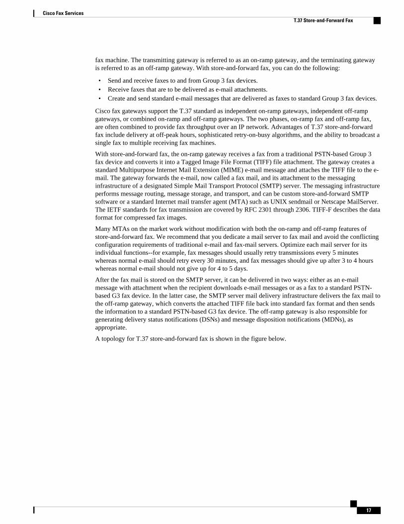
fax machine. The transmitting gateway is referred to as an on-ramp gateway, and the terminating gatewayis referred to as an off-ramp gateway. With store-and-forward fax, you can do the following:
• Send and receive faxes to and from Group 3 fax devices.• Receive faxes that are to be delivered as e-mail attachments.• Create and send standard e-mail messages that are delivered as faxes to standard Group 3 fax devices.
Cisco fax gateways support the T.37 standard as independent on-ramp gateways, independent off-rampgateways, or combined on-ramp and off-ramp gateways. The two phases, on-ramp fax and off-ramp fax,are often combined to provide fax throughput over an IP network. Advantages of T.37 store-and-forwardfax include delivery at off-peak hours, sophisticated retry-on-busy algorithms, and the ability to broadcast asingle fax to multiple receiving fax machines.
With store-and-forward fax, the on-ramp gateway receives a fax from a traditional PSTN-based Group 3fax device and converts it into a Tagged Image File Format (TIFF) file attachment. The gateway creates astandard Multipurpose Internet Mail Extension (MIME) e-mail message and attaches the TIFF file to the e-mail. The gateway forwards the e-mail, now called a fax mail, and its attachment to the messaginginfrastructure of a designated Simple Mail Transport Protocol (SMTP) server. The messaging infrastructureperforms message routing, message storage, and transport, and can be custom store-and-forward SMTPsoftware or a standard Internet mail transfer agent (MTA) such as UNIX sendmail or Netscape MailServer.The IETF standards for fax transmission are covered by RFC 2301 through 2306. TIFF-F describes the dataformat for compressed fax images.
Many MTAs on the market work without modification with both the on-ramp and off-ramp features ofstore-and-forward fax. We recommend that you dedicate a mail server to fax mail and avoid the conflictingconfiguration requirements of traditional e-mail and fax-mail servers. Optimize each mail server for itsindividual functions--for example, fax messages should usually retry transmissions every 5 minuteswhereas normal e-mail should retry every 30 minutes, and fax messages should give up after 3 to 4 hourswhereas normal e-mail should not give up for 4 to 5 days.
After the fax mail is stored on the SMTP server, it can be delivered in two ways: either as an e-mailmessage with attachment when the recipient downloads e-mail messages or as a fax to a standard PSTN-based G3 fax device. In the latter case, the SMTP server mail delivery infrastructure delivers the fax mail tothe off-ramp gateway, which converts the attached TIFF file back into standard fax format and then sendsthe information to a standard PSTN-based G3 fax device. The off-ramp gateway is also responsible forgenerating delivery status notifications (DSNs) and message disposition notifications (MDNs), asappropriate.
A topology for T.37 store-and-forward fax is shown in the figure below.
Cisco Fax ServicesT.37 Store-and-Forward Fax
17
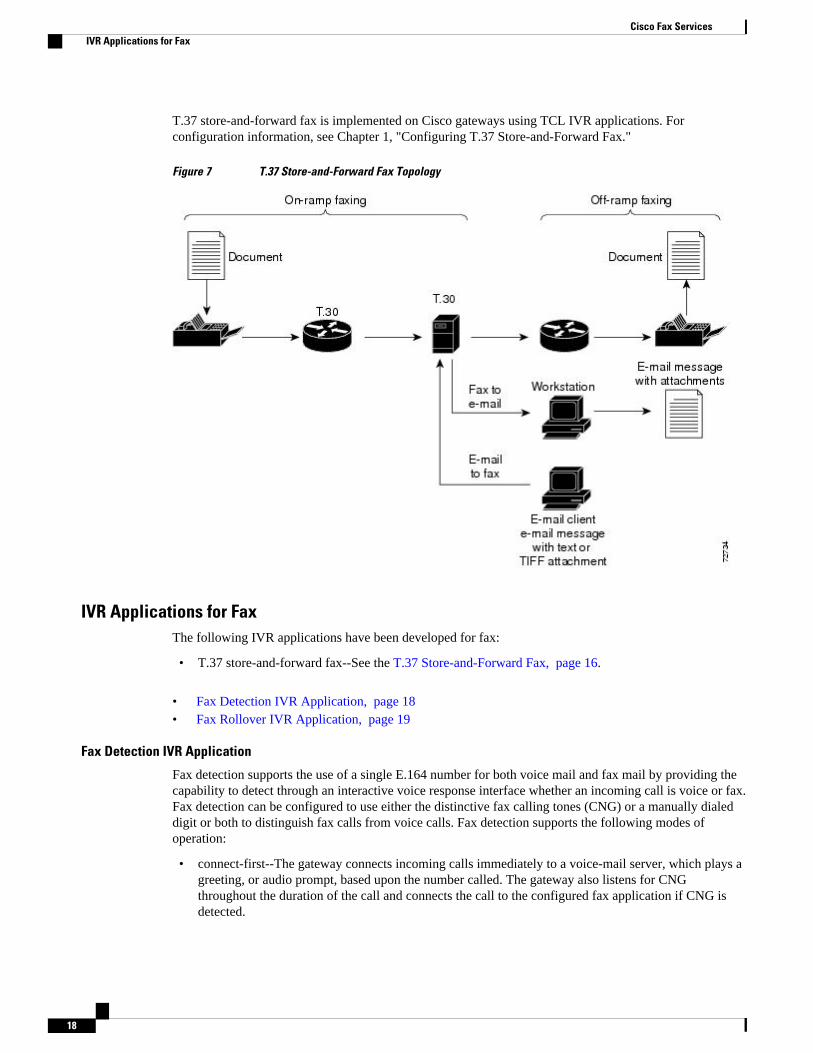
T.37 store-and-forward fax is implemented on Cisco gateways using TCL IVR applications. Forconfiguration information, see Chapter 1, "Configuring T.37 Store-and-Forward Fax."
Figure 7 T.37 Store-and-Forward Fax Topology
IVR Applications for FaxThe following IVR applications have been developed for fax:
• T.37 store-and-forward fax--See the T.37 Store-and-Forward Fax, page 16.
• Fax Detection IVR Application, page 18• Fax Rollover IVR Application, page 19
Fax Detection IVR Application
Fax detection supports the use of a single E.164 number for both voice mail and fax mail by providing thecapability to detect through an interactive voice response interface whether an incoming call is voice or fax.Fax detection can be configured to use either the distinctive fax calling tones (CNG) or a manually dialeddigit or both to distinguish fax calls from voice calls. Fax detection supports the following modes ofoperation:
• connect-first--The gateway connects incoming calls immediately to a voice-mail server, which plays agreeting, or audio prompt, based upon the number called. The gateway also listens for CNGthroughout the duration of the call and connects the call to the configured fax application if CNG isdetected.
Cisco Fax Services IVR Applications for Fax
18
• listen-first--The gateway listens for CNG for 9 seconds; an audio prompt can be played during thistime. If CNG is detected, the call is connected to a fax application or server. If CNG is not detected,the call is connected to a voice application or server.
• default-voice--The gateway is configured to recognize a particular dual tone multifrequency (DTMF)tone to indicate voice calls and a different DTMF tone to indicate fax calls. If no DTMF tone is heardand no CNG tone is heard for 9 seconds, the call is treated as a voice call.
• default-fax--The gateway is configured to recognize a particular DTMF tone to indicate voice calls anda different DTMF tone to indicate fax calls. If no DTMF tone is heard and no CNG tone is heard for 9seconds, the call is treated as a fax call.
For configuration information, see Chapter 1, "Configuring Fax Detection."
Fax Rollover IVR Application
The fax rollover IVR application provides a configured fallback to T.37 store-and-forward fax if a callattempts to use fax relay and fails. An OGW must be configured with fax relay, store-and-forward fax, andalso with the fax rollover application. Then, if a fax relay attempt fails, the call is forwarded to an SMTPserver by a mail transfer agent (MTA) using T.37-standard protocols for store-and-forward fax.
For configuration information, see Chapter 1, "Configuring Fax Rollover."
Information About Cisco IOS Modem Services over IP• Modem Passthrough over VoIP, page 19• Modem Relay over VoIP, page 21
Modem Passthrough over VoIPWhen service providers and aggregators are implementing VoIP, they sometimes cannot separate datatraffic from voice traffic. These carriers that aggregate voice traffic over VoIP infrastructures requireservice offerings to carry data as easily as voice.
Modem passthrough over VoIP provides for the transport of modem signals through a packet network byusing pulse code modulation (PCM)-encoded packets.
Modem passthrough performs the following functions:
• Suppressing processing functions like compression, echo cancellation, high-pass filter, and voiceactivity detection (VAD)
• Issuing redundant packets to protect against random packet drops• Providing static jitter buffers of 200 milliseconds (ms) to protect against clock skew• Differentiating modem signals from voice and fax signals, indicating the detection of the modem
signal across the connection, and placing the connection in a state that transports the signal across thenetwork with the least distortion
• Maintaining a modem connection reliably across the packet network for a long duration under normalnetwork conditions
On detection of the modem answer tone, the gateways switch into modem passthrough mode. With modempassthrough, the modem traffic is carried between the two gateways in real-time transport protocol (RTP)packets, using an uncompressed or lightly compressed voice codec--G.711 u-law, G.711 a-law, or VoiceBand Data (VBD). Packet redundancy may be used to mitigate the effects of packet loss in the IP network.Even so, modem passthrough remains susceptible to packet loss, jitter, and latency in the IP network.
Modem Passthrough over VoIPFax Rollover IVR Application
19
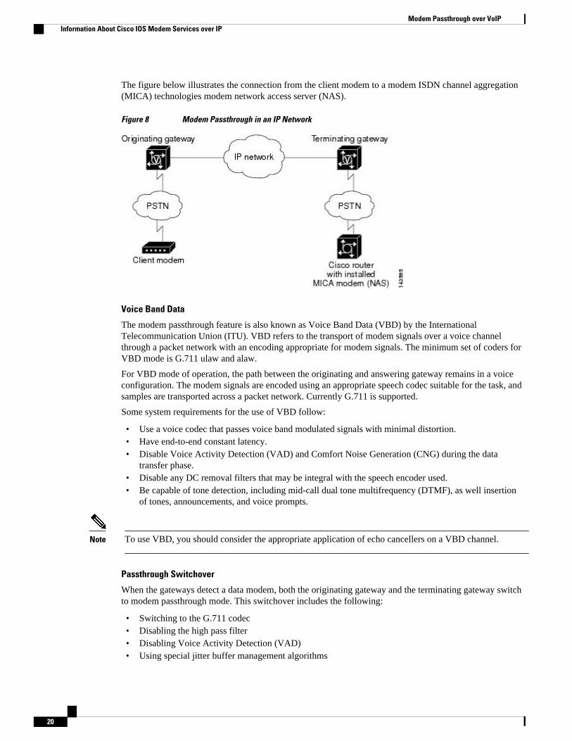
The figure below illustrates the connection from the client modem to a modem ISDN channel aggregation(MICA) technologies modem network access server (NAS).
Figure 8 Modem Passthrough in an IP Network
Voice Band Data
The modem passthrough feature is also known as Voice Band Data (VBD) by the InternationalTelecommunication Union (ITU). VBD refers to the transport of modem signals over a voice channelthrough a packet network with an encoding appropriate for modem signals. The minimum set of coders forVBD mode is G.711 ulaw and alaw.
For VBD mode of operation, the path between the originating and answering gateway remains in a voiceconfiguration. The modem signals are encoded using an appropriate speech codec suitable for the task, andsamples are transported across a packet network. Currently G.711 is supported.
Some system requirements for the use of VBD follow:
• Use a voice codec that passes voice band modulated signals with minimal distortion.• Have end-to-end constant latency.• Disable Voice Activity Detection (VAD) and Comfort Noise Generation (CNG) during the data
transfer phase.• Disable any DC removal filters that may be integral with the speech encoder used.• Be capable of tone detection, including mid-call dual tone multifrequency (DTMF), as well insertion
of tones, announcements, and voice prompts.
Note To use VBD, you should consider the appropriate application of echo cancellers on a VBD channel.
Passthrough Switchover
When the gateways detect a data modem, both the originating gateway and the terminating gateway switchto modem passthrough mode. This switchover includes the following:
• Switching to the G.711 codec• Disabling the high pass filter• Disabling Voice Activity Detection (VAD)• Using special jitter buffer management algorithms
Modem Passthrough over VoIP Information About Cisco IOS Modem Services over IP
20
• On detection of modem phase reversal tone, disabling the echo canceler
At the end of the modem or fax call, the voice ports revert to the previous configuration and the DSPsswitch back to the original voice codec.
Note The gateway detects modems operating at speeds up to V.90.
Controlled Redundancy
Packet loss is a persistent issue in voice applications. The disruption of speech, which is characteristic ofpacket loss, can be somewhat resolved with controlled redundancy and the RTP (RFC 2198). Controlledredundancy reconstructs missing information at the receiver end from the redundant data that arrives in thetransmitted packets.
Some of the requirements for a controlled redundancy are as follows:
• The packets have to carry a primary encoding and one redundant encoding.• Because the use of variable size encodings is desirable, each encoded block in the packet must have a
length indicator.• The RTP header provides a time-stamp field that corresponds to the time of creation of the encoded
data and redundant blocks of data correspond to different time intervals than the primary data. So eachblock of redundant encoding requires its own time stamp.
You can enable redundancy so that the modem and fax passthrough switchover causes the gateway totransmit redundant packets and redundancy can be enabled in one or both of the gateways. When only onegateway is configured, the other gateway receives the packets correctly, but does not produce redundantpackets. When redundancy is enabled, 10-ms sample-sized packets are sent. When redundancy is disabled,20-ms sample-sized packets are sent.
Note The current Cisco implementation of RFC 2198 reflects a redundant encoding of 1X or 1 repeat of theoriginal packet. This means that any loss scenario in which two or more consecutive packets are droppedwould cause a loss of data translated into a retrain, Failure To Train (FTT), or call drop, etc. in modem andfax passthrough.
Clock Slip Buffer Management
When the gateways detect a data modem, both the originating gateway and the terminating gateway switchfrom dynamic and adaptive buffers to static de-jitter buffers. The use of a static de-jitter buffer is requiredfor modem passthrough because the adaptation process in a dynamic de-jitter buffer causes a retrain on themodem connection. When the modem call is concluded, the voice ports revert to dynamic jitter buffers.
In addition, the modem passthrough data management algorithm is designed to handle and compensate forclocking differences in the PSTN between the originating and terminating gateways. This additional clock-slip monitoring prevents issues that show up in long duration modem calls.
Modem Relay over VoIPThe Modem Relay feature provides support for modem connections across traditional time-divisionmultiplexing (TDM) networks. Modem relay demodulates a modem signal at one voice gateway and passesit as packet data to another voice gateway where the signal is remodulated and sent to a receiving modem.
Modem Relay over VoIPInformation About Cisco IOS Modem Services over IP
21
On detection of the modem answer tone, the gateways switch into modem passthrough mode and then, ifthe call menu (CM) signal is detected, the two gateways switch into modem relay mode.
Differences Between Modem Passthrough and Modem Relay
There are two ways to transport modem traffic over VoIP networks:
• With modem passthrough, the modem traffic is carried between the two gateways in RTP packets,using an uncompressed voice codec--G.711 u-law or a-law. Although modem passthrough remainssusceptible to packet loss, jitter, and latency in the IP network, packet redundancy may be used tomitigate the effects of packet loss in the IP network.
• With modem relay, the modem signals are demodulated at one gateway, converted to digital form, andcarried in Simple Packet Relay Transport (SPRT) protocol (which is a protocol running over UserDatagram Protocol (UDP)) packets to the other gateway, where the modem signal is recreated andremodulated, and passed to the receiving modem.
In this implementation, the call starts out as a voice call, then switches into modem passthrough mode, andthen into modem relay mode.
Modem Tone Detection and Signaling
This implementation of modem relay supports V.34 modulation and the V.42 error correction and link layerprotocol with maximum transfer rates of up to 33.6 kbps. It forces higher-rate modems to train down to thesupported rates. Signaling support includes the Session Initiation Protocol (SIP), MGCP/SGCP, and H.323:
• For MGCP and SIP, during the call setup, the gateways negotiate the following:
◦ To use or not use modem relay mode◦ To use or not use gateway exchange identification◦ The value of the payload type for NSE packets
• For H.323, the gateways negotiate the following:
◦ To use or not use modem relay mode◦ To use or not use gateway exchange identification
Benifits of Modem Relay
Modem relay on VoIP offers the following benefits:
• Modem tone detection• Packetized modem signal transmission over the WAN• Significant reduction of dropped packet, latency, and jitter effects on modem sessions• Reduction of bandwidth used (as compared to modem passthrough)
Packet Redundancy
You can enable payload redundancy so that the modem relay VoIP switchover causes the gateway to sendredundant packets. Redundancy can be enabled in one or both of the gateways. When only a single gatewayis configured for redundancy, the other gateway receives the packets correctly, but does not produceredundant packets. When redundancy is enabled, 10-ms sample-sized packets are sent. When redundancy isdisabled, 20-ms sample-sized packets are sent.
Modem Relay over VoIP Information About Cisco IOS Modem Services over IP
22
Note By default, modem relay over VoIP capability and redundancy are disabled.
Clock Slip Buffer Management
When the gateways detect a data modem, both the originating and the terminating gateways switch fromdynamic jitter buffers to static jitter buffers of 200-ms depth. The switch from dynamic to static is designedto compensate for Public Switched Telephone Network (PSTN) clocking differences at the originating andterminating gateways. When the modem call is concluded, the voice ports revert to dynamic jitter buffers.
Additional ReferencesDeveloper Support
Developers using this guide may be interested in joining the Cisco Developer Support Program. Thisprogram was created to provide you with a consistent level of support that you can depend on whileleveraging Cisco interfaces in your development projects.
The Developer Support Program provides formalized support for Cisco Systems interfaces to enabledevelopers, customers, and partners in the Cisco Technology Developer program to accelerate theirdelivery of compatible solutions.
The Developer Support Engineers are an extension of the product technology engineering teams. They havedirect access to the resources necessary to provide expert support in a timely manner.
For additional information on this General Support and Program FAQ's refer to the Developer SupportProgram Web Site at www.cisco.com/go/developersupport/ or contact [email protected].
Note Cisco Technical Assistance Center (TAC) support does not include Cisco Developer Support and is limitedto Cisco product installation/configuration and Cisco-developed applications. A signed Developer SupportAgreement is required to participate in this program. For more details on how to obtain a DeveloperSupport agreement go to http://www.cisco.com/go/developersupport under "Ordering" or [email protected].
Related DocumentsRelated Topic Document Title
Cisco IOS Voice Configuration Library, includinglibrary preface and glossary, other featuredocuments, and troubleshooting documentation.
Cisco IOS Voice Configuration Library
Cisco IOS command references • Cisco IOS Debug Command Reference• Cisco IOS Voice Command Reference
Modem Relay over VoIPAdditional References
23
Related Topic Document Title
Cisco IOS security features, includingauthentication, authorization, and accounting(AAA)
Cisco IOS Security Configuration Guide
Cisco IOS TCL, VoiceXML, and IVR applications TCL IVR API Version 2.0 Programmer’s Guide
Cisco VoiceXML Programmer’s Guide
Cisco IOS voice troubleshooting information Cisco IOS Voice Troubleshooting and MonitoringGuide
Cisco MGCP configuration information Cisco IOS MGCP and Related ProtocolsConfiguration Guide
Cisco SIP configuration information Cisco IOS SIP Configuration Guide
Network configuration Cisco IOS IP Application Services ConfigurationGuide
StandardsStandards1 Title
ITU-T T.4 Standardization of Group 3 facsimile terminals fordocument transmission
ITU-T T.30 Procedures for document facsimile transmission inthe general switched telephone network
ITU-T.37 Procedures for the Transfer of Facsimile Data viaStore-and-Forward on the Internet, June 1998
ITU-T.38 Procedures for Real-Time Group 3 FacsimileCommunication over IP Networks, June 1998
ITU-T.38 Procedures for Real-Time Group 3 FacsimileCommunication over IP Networks, Amendment 1,April 1999
ITU-T.38 Revised Annex B of Recommendation T.38,November 1998
ITU-T.38 Revised Annex D of Recommendation T.38,November 1998
Fax Standards
1 Not all supported standards are listed.
Modem Relay over VoIP Standards
24
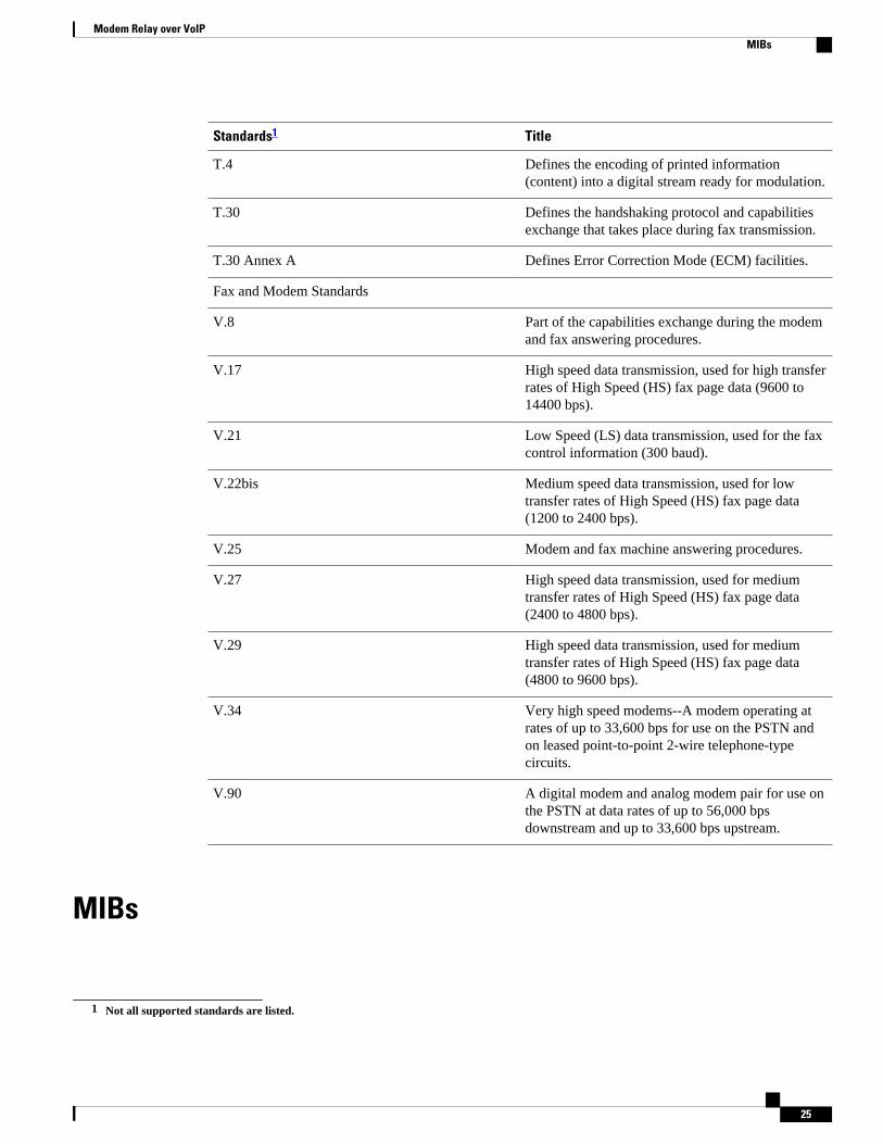
Standards1 Title
T.4 Defines the encoding of printed information(content) into a digital stream ready for modulation.
T.30 Defines the handshaking protocol and capabilitiesexchange that takes place during fax transmission.
T.30 Annex A Defines Error Correction Mode (ECM) facilities.
Fax and Modem Standards
V.8 Part of the capabilities exchange during the modemand fax answering procedures.
V.17 High speed data transmission, used for high transferrates of High Speed (HS) fax page data (9600 to14400 bps).
V.21 Low Speed (LS) data transmission, used for the faxcontrol information (300 baud).
V.22bis Medium speed data transmission, used for lowtransfer rates of High Speed (HS) fax page data(1200 to 2400 bps).
V.25 Modem and fax machine answering procedures.
V.27 High speed data transmission, used for mediumtransfer rates of High Speed (HS) fax page data(2400 to 4800 bps).
V.29 High speed data transmission, used for mediumtransfer rates of High Speed (HS) fax page data(4800 to 9600 bps).
V.34 Very high speed modems--A modem operating atrates of up to 33,600 bps for use on the PSTN andon leased point-to-point 2-wire telephone-typecircuits.
V.90 A digital modem and analog modem pair for use onthe PSTN at data rates of up to 56,000 bpsdownstream and up to 33,600 bps upstream.
MIBs
1 Not all supported standards are listed.
Modem Relay over VoIPMIBs
25
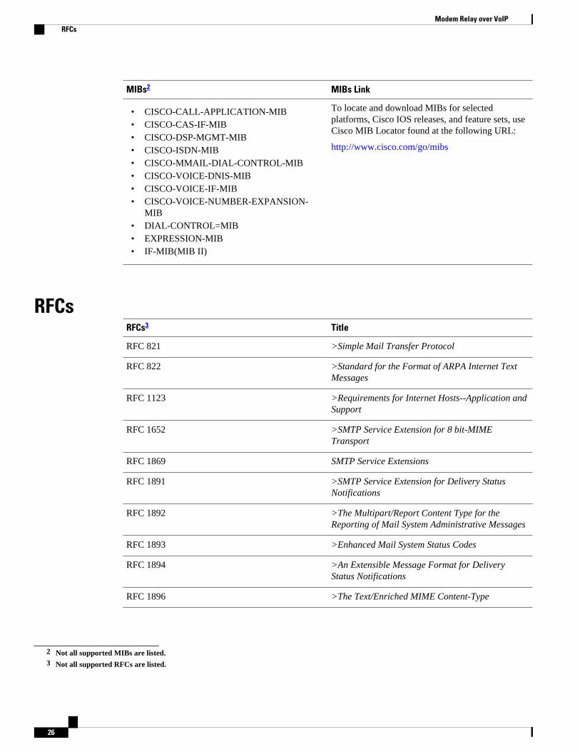
MIBs2 MIBs Link
• CISCO-CALL-APPLICATION-MIB• CISCO-CAS-IF-MIB• CISCO-DSP-MGMT-MIB• CISCO-ISDN-MIB• CISCO-MMAIL-DIAL-CONTROL-MIB• CISCO-VOICE-DNIS-MIB• CISCO-VOICE-IF-MIB• CISCO-VOICE-NUMBER-EXPANSION-
MIB• DIAL-CONTROL=MIB• EXPRESSION-MIB• IF-MIB(MIB II)
To locate and download MIBs for selectedplatforms, Cisco IOS releases, and feature sets, useCisco MIB Locator found at the following URL:
http://www.cisco.com/go/mibs
RFCsRFCs3 Title
RFC 821 >Simple Mail Transfer Protocol
RFC 822 >Standard for the Format of ARPA Internet TextMessages
RFC 1123 >Requirements for Internet Hosts--Application andSupport
RFC 1652 >SMTP Service Extension for 8 bit-MIMETransport
RFC 1869 SMTP Service Extensions
RFC 1891 >SMTP Service Extension for Delivery StatusNotifications
RFC 1892 >The Multipart/Report Content Type for theReporting of Mail System Administrative Messages
RFC 1893 >Enhanced Mail System Status Codes
RFC 1894 >An Extensible Message Format for DeliveryStatus Notifications
RFC 1896 >The Text/Enriched MIME Content-Type
2 Not all supported MIBs are listed.3 Not all supported RFCs are listed.
Modem Relay over VoIP RFCs
26
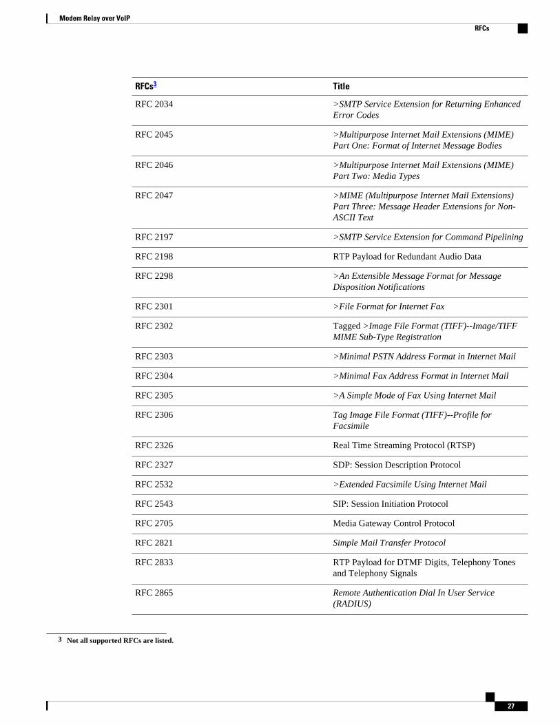
RFCs3 Title
RFC 2034 >SMTP Service Extension for Returning EnhancedError Codes
RFC 2045 >Multipurpose Internet Mail Extensions (MIME)Part One: Format of Internet Message Bodies
RFC 2046 >Multipurpose Internet Mail Extensions (MIME)Part Two: Media Types
RFC 2047 >MIME (Multipurpose Internet Mail Extensions)Part Three: Message Header Extensions for Non-ASCII Text
RFC 2197 >SMTP Service Extension for Command Pipelining
RFC 2198 RTP Payload for Redundant Audio Data
RFC 2298 >An Extensible Message Format for MessageDisposition Notifications
RFC 2301 >File Format for Internet Fax
RFC 2302 Tagged >Image File Format (TIFF)--Image/TIFFMIME Sub-Type Registration
RFC 2303 >Minimal PSTN Address Format in Internet Mail
RFC 2304 >Minimal Fax Address Format in Internet Mail
RFC 2305 >A Simple Mode of Fax Using Internet Mail
RFC 2306 Tag Image File Format (TIFF)--Profile forFacsimile
RFC 2326 Real Time Streaming Protocol (RTSP)
RFC 2327 SDP: Session Description Protocol
RFC 2532 >Extended Facsimile Using Internet Mail
RFC 2543 SIP: Session Initiation Protocol
RFC 2705 Media Gateway Control Protocol
RFC 2821 Simple Mail Transfer Protocol
RFC 2833 RTP Payload for DTMF Digits, Telephony Tonesand Telephony Signals
RFC 2865 Remote Authentication Dial In User Service(RADIUS)
3 Not all supported RFCs are listed.
Modem Relay over VoIPRFCs
27
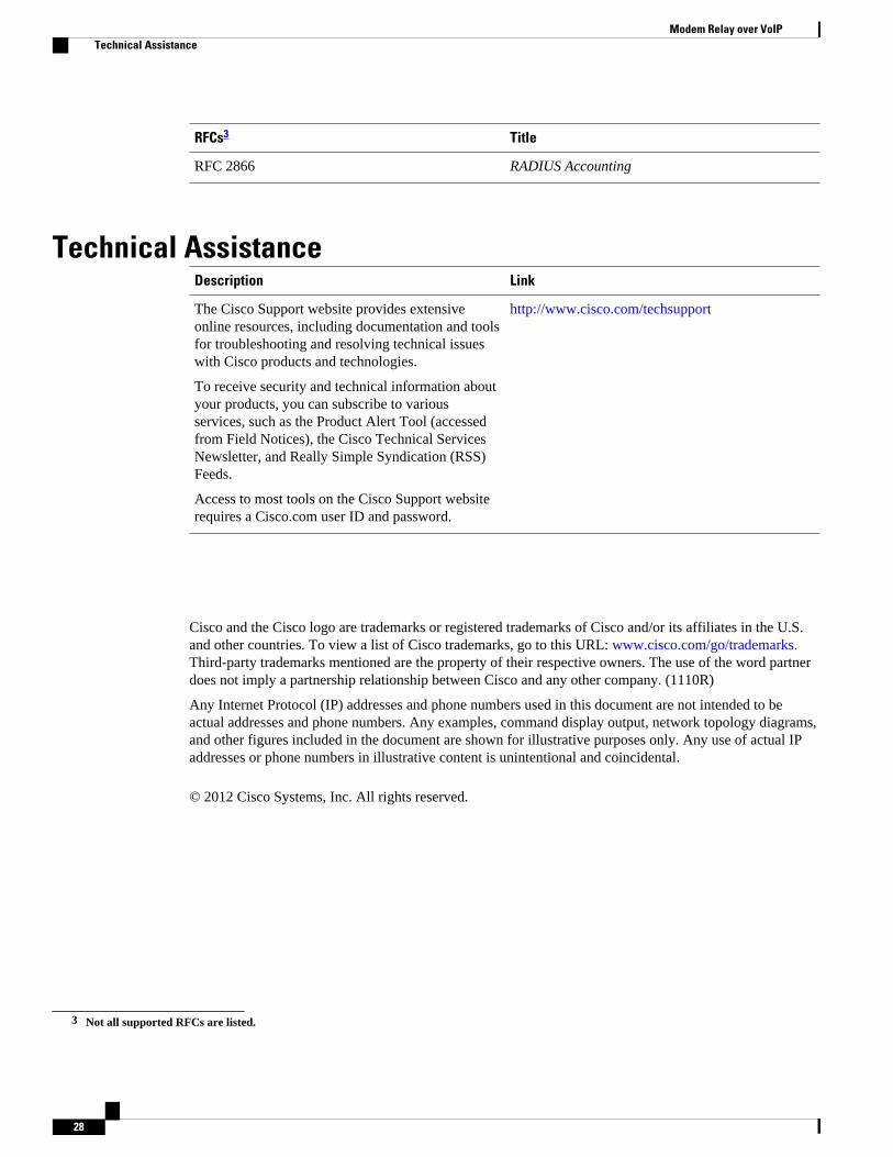
RFCs3 Title
RFC 2866 RADIUS Accounting
Technical AssistanceDescription Link
The Cisco Support website provides extensiveonline resources, including documentation and toolsfor troubleshooting and resolving technical issueswith Cisco products and technologies.
To receive security and technical information aboutyour products, you can subscribe to variousservices, such as the Product Alert Tool (accessedfrom Field Notices), the Cisco Technical ServicesNewsletter, and Really Simple Syndication (RSS)Feeds.
Access to most tools on the Cisco Support websiterequires a Cisco.com user ID and password.
http://www.cisco.com/techsupport
Cisco and the Cisco logo are trademarks or registered trademarks of Cisco and/or its affiliates in the U.S.and other countries. To view a list of Cisco trademarks, go to this URL: www.cisco.com/go/trademarks.Third-party trademarks mentioned are the property of their respective owners. The use of the word partnerdoes not imply a partnership relationship between Cisco and any other company. (1110R)
Any Internet Protocol (IP) addresses and phone numbers used in this document are not intended to beactual addresses and phone numbers. Any examples, command display output, network topology diagrams,and other figures included in the document are shown for illustrative purposes only. Any use of actual IPaddresses or phone numbers in illustrative content is unintentional and coincidental.
© 2012 Cisco Systems, Inc. All rights reserved.
3 Not all supported RFCs are listed.
Modem Relay over VoIP Technical Assistance
28