Embed Size (px)
Citation preview

Andover Controls Corp.World Headquarters300 Brickstone SquareAndover, Massachusetts01810 USATel: +1 978 470 0555Fax: +1 978 470 0946
Andover Controls Ltd.Smisby RoadAshby-de-la-ZouchLeicestershire LE65 2UGEnglandTel: +44 1530 417733Fax: +44 1530 415436
Andover Controls GmbHAm Seerhein 8D-78467 KonstanzGermanyTel: +49 7531 99370Fax: +49 7531 993710
Andover Controls S.A.Immeuble Dolomites 258 Rue Roger Salengro94126 Fontenay SousBois Cedex, FranceTel: +33 1 53 99 16 16Fax: +33 1 53 99 16 15
Andover Controls AsiaUnit 1201-02, Phase 1,Cheuk Nang Centre9 Hillwood Road,Tsim Sha Tsui EastKowloon, Hong KongTel: +852 2739 5497Fax: +852 2739 7350
Andover ControlsLatin AmericaInsurgentes 1722-501Col. FloridaMexico D.F. 01030, MexicoTel: +5255 5661 5672Fax: +5255 5661 5415
©2002 Andover Controls Corporation • All brand names, trademarks and registered trademarks are the property of their respective holders. BR-WC-AA Balfour Beatty Company
www.andovercontrols.com
Specifications
Manage Your Entire Facility:
. . .from a Single Browser Interface!
Environmental Control
Security/Access Control
Video Surveillance
Alarm and Event Monitoring
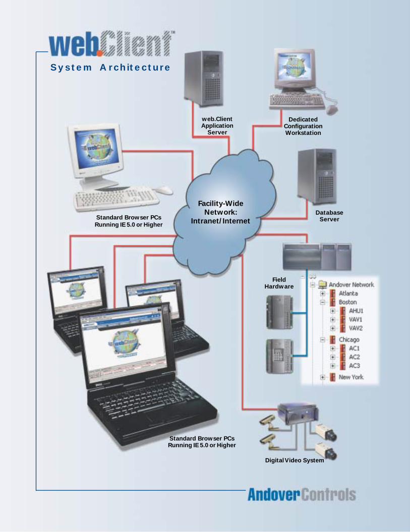
System Architecture
Facility-Wide
Network:
Intranet/Internet
DatabaseServer
DedicatedConfigurationWorkstation
web.ClientApplication
Server
Digital Video System
FieldHardware
Standard Browser PCsRunning IE 5.0 or Higher
Standard Browser PCs
Running IE 5.0 or Higher
web.Client requires a Continuum LAN system, revision 1.5 or greater, comprised of at leastone dedicated workstation plus the following web.Client specific requirements:
Application Server:Operating System: MS Windows NT Server 4.0; Windows 2000 Server Professional
Internet Server: MS Internet Information Services (IIS) 4.0 or higher with Active ServerPages (ASP) enabled
Minimum Hardware: Pentium III 700 MHz, 512MB RAM, CD-ROM, Parallel or USB port
Client Browser:Windows 98/NT/2000/XP PC running MS Internet Explorer 5.0 or higher, Java-enabled,18-30MB minimum hard drive space.
Network Connectivity:TCP/IP. web.Client Pro graphics viewer uses DCOM and requires local LAN connection orhigh-speed VPN connection to the application server.
User Security:Continuum user accounts (encrypted). Database may be partitioned such that users haveaccess to only certain collections of objects in the system. Examples include partitioningby site, by building, by function (HVAC or security, etc.), by department.
User Auto-Logoff:Yes, after 20 minutes of inactivity that can be customized by administrator.
Encryption: Support for IIS Secure Socket Layer (SSL)
Maximum Simultaneous Users per Server: 25(contact Andover Controls if you require more than 25)
Additional Server RAM Required per Connection: 5MB
Maximum Card Records in Database: 4 million
Maximum Card History: Limited only by disk space
Video Integration:Live and recorded video from digital video recorders. Supported DVR’s:Integral DVX 2.2 or higher, and XPress Integrated 1.1 or higher.
Licensing: web.Client is available in two versions:web.Client Personnel Manager includes: personnel editing, reporting, andschedulingweb.Client Pro includes: graphics, alarms, live event window, groups, explorer/search, video integration, plus the Personnel Manager features
In addition, web.Client is sold by the number of concurrent users connected to theapplication server. Both versions are available in packages for 5, 10, 15, 20, and 25concurrent users. You cannot mix Personnel Manager and Pro versions on the same server.Licensing managed from a parallel or USB port key on the web.Client application server.
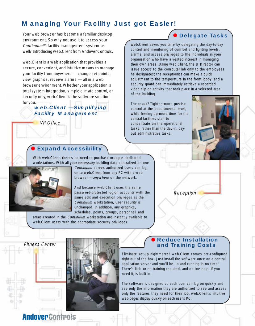
web.Client saves you time by delegating the day-to-daycontrol and monitoring of comfort and lighting levels,alarms, and access privileges to the individuals in yourorganization who have a vested interest in managingtheir own areas. Using web.Client, the IT Director canissue access to the computer lab only to the employeeshe designates; the receptionist can make a quickadjustment to the temperature in the front lobby; and asecurity guard can immediately retrieve a recordedvideo clip on activity that took place in a selected areaof the building.
The result? Tighter, more precisecontrol at the departmental level,while freeing up more time for thecentral facilities staff toconcentrate on the operationaltasks, rather than the day-in, day-out administrative tasks.
Delegate Tasks
Expand Accessibility
With web.Client, there’s no need to purchase multiple dedicatedworkstations. With all your necessary building data centralized on one
Continuum server, authorized users can logon to web.Client from any PC with a webbrowser —anywhere on the network.
And because web.Client uses the samepassword-protected log-on accounts with thesame edit and execution privileges as theContinuum workstation, user security isunchanged. In addition, any graphics,schedules, points, groups, personnel, and
areas created in the Continuum workstation are instantly available toweb.Client users with the appropriate security privileges.
Reduce Installationand Training Costs
Eliminate set-up nightmares! web.Client comes pre-configuredright out of the box! Just install the software once on a centralapplication server and you’ll be up and running in no time!There’s little or no training required, and on-line help, if youneed it, is built in.
The software is designed so each user can log on quickly andsee only the information they are authorized to see and accessonly the features they need for their job. web.Client’s intuitiveweb pages display quickly on each user’s PC.
web.Client —SimplifyingFacility Management
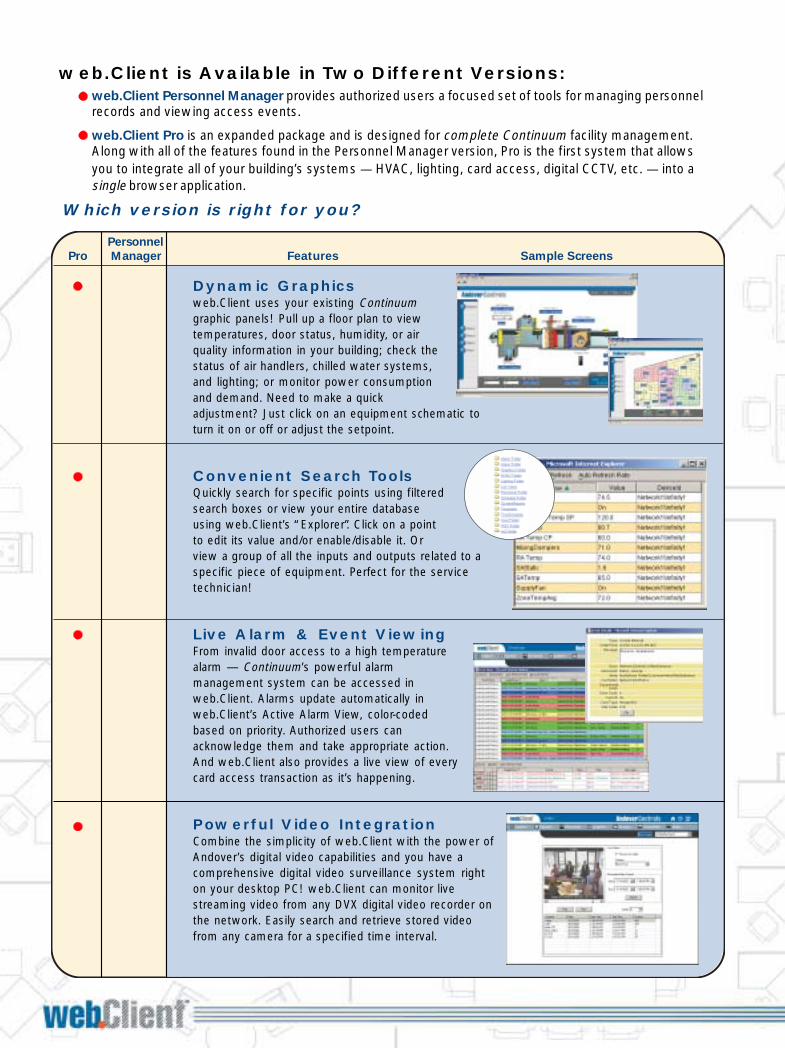
Managing Your Facility Just got Easier! web.Client is Available in Two Different Versions:web.Client Personnel Manager provides authorized users a focused set of tools for managing personnelrecords and viewing access events.
web.Client Pro is an expanded package and is designed for complete Continuum facility management.Along with all of the features found in the Personnel Manager version, Pro is the first system that allowsyou to integrate all of your building’s systems — HVAC, lighting, card access, digital CCTV, etc. — into asingle browser application.
Dynamic Graphicsweb.Client uses your existing Continuumgraphic panels! Pull up a floor plan to viewtemperatures, door status, humidity, or airquality information in your building; check thestatus of air handlers, chilled water systems,and lighting; or monitor power consumptionand demand. Need to make a quickadjustment? Just click on an equipment schematic toturn it on or off or adjust the setpoint.
Convenient Search ToolsQuickly search for specific points using filteredsearch boxes or view your entire databaseusing web.Client’s “Explorer”. Click on a pointto edit its value and/or enable/disable it. Orview a group of all the inputs and outputs related to aspecific piece of equipment. Perfect for the servicetechnician!
Live Alarm & Event ViewingFrom invalid door access to a high temperaturealarm — Continuum’s powerful alarmmanagement system can be accessed inweb.Client. Alarms update automatically inweb.Client’s Active Alarm View, color-codedbased on priority. Authorized users canacknowledge them and take appropriate action.And web.Client also provides a live view of everycard access transaction as it’s happening.
Powerful Video IntegrationCombine the simplicity of web.Client with the power ofAndover’s digital video capabilities and you have acomprehensive digital video surveillance system righton your desktop PC! web.Client can monitor livestreaming video from any DVX digital video recorder onthe network. Easily search and retrieve stored videofrom any camera for a specified time interval.
Personnel
Pro Manager Features Sample Screens
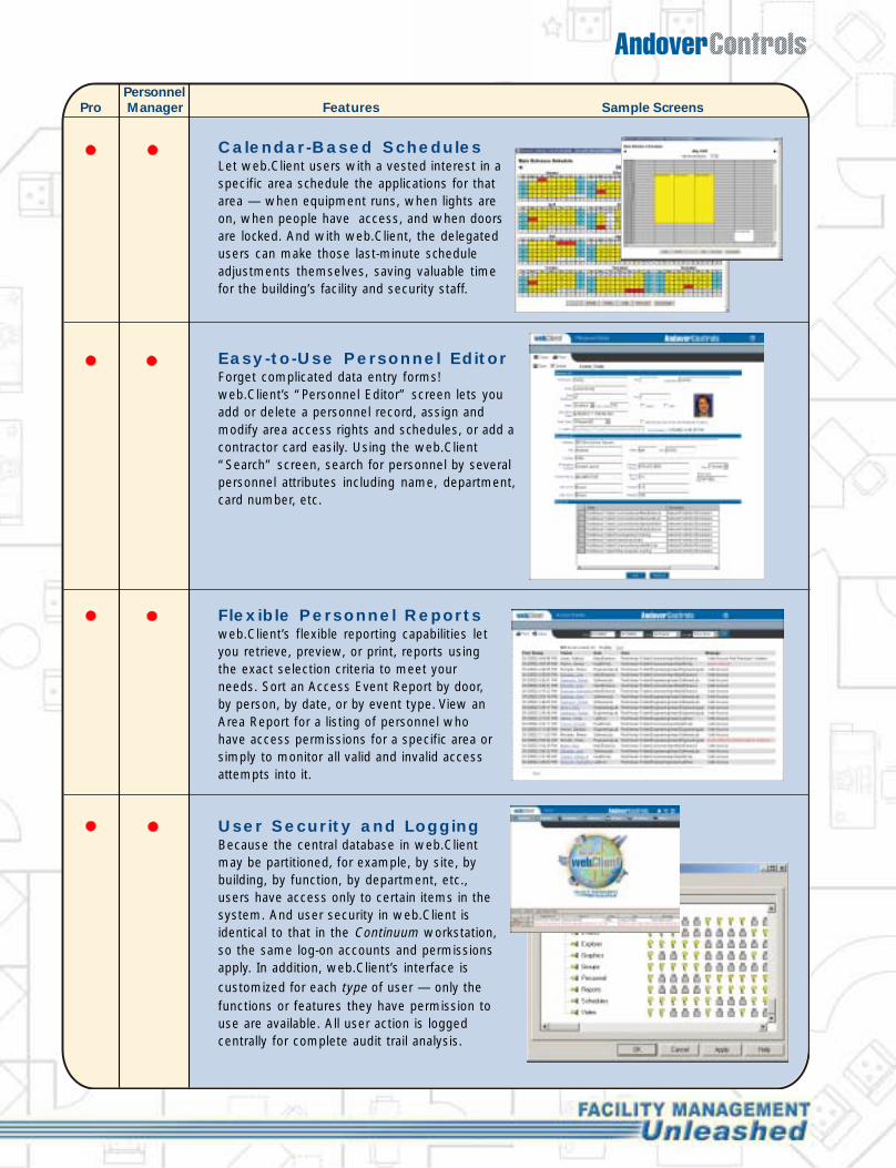
Calendar-Based SchedulesLet web.Client users with a vested interest in aspecific area schedule the applications for thatarea — when equipment runs, when lights areon, when people have access, and when doorsare locked. And with web.Client, the delegatedusers can make those last-minute scheduleadjustments themselves, saving valuable timefor the building’s facility and security staff.
Easy-to-Use Personnel EditorForget complicated data entry forms!web.Client’s “Personnel Editor” screen lets youadd or delete a personnel record, assign andmodify area access rights and schedules, or add acontractor card easily. Using the web.Client“Search” screen, search for personnel by severalpersonnel attributes including name, department,card number, etc.
Flexible Personnel Reportsweb.Client’s flexible reporting capabilities letyou retrieve, preview, or print, reports usingthe exact selection criteria to meet yourneeds. Sort an Access Event Report by door,by person, by date, or by event type. View anArea Report for a listing of personnel whohave access permissions for a specific area orsimply to monitor all valid and invalid accessattempts into it.
User Security and LoggingBecause the central database in web.Clientmay be partitioned, for example, by site, bybuilding, by function, by department, etc.,users have access only to certain items in thesystem. And user security in web.Client isidentical to that in the Continuum workstation,so the same log-on accounts and permissionsapply. In addition, web.Client’s interface iscustomized for each type of user — only thefunctions or features they have permission touse are available. All user action is loggedcentrally for complete audit trail analysis.
Personnel
Pro Manager Features Sample Screens
Which version is right for you?
VP Office
Fitness Center
Reception
Your web browser has become a familiar desktopenvironment. So why not use it to access yourContinuumTM facility management system aswell? Introducing web.Client from Andover Controls.
web.Client is a web application that provides asecure, convenient, and intuitive means to manageyour facility from anywhere — change set points,view graphics, receive alarms — all in a webbrowser environment. Whether your application istotal system integration, simple climate control, orsecurity only, web.Client is the software solutionfor you.
web.Client saves you time by delegating the day-to-daycontrol and monitoring of comfort and lighting levels,alarms, and access privileges to the individuals in yourorganization who have a vested interest in managingtheir own areas. Using web.Client, the IT Director canissue access to the computer lab only to the employeeshe designates; the receptionist can make a quickadjustment to the temperature in the front lobby; and asecurity guard can immediately retrieve a recordedvideo clip on activity that took place in a selected areaof the building.
The result? Tighter, more precisecontrol at the departmental level,while freeing up more time for thecentral facilities staff toconcentrate on the operationaltasks, rather than the day-in, day-out administrative tasks.
Delegate Tasks
Expand Accessibility
With web.Client, there’s no need to purchase multiple dedicatedworkstations. With all your necessary building data centralized on one
Continuum server, authorized users can logon to web.Client from any PC with a webbrowser —anywhere on the network.
And because web.Client uses the samepassword-protected log-on accounts with thesame edit and execution privileges as theContinuum workstation, user security isunchanged. In addition, any graphics,schedules, points, groups, personnel, and
areas created in the Continuum workstation are instantly available toweb.Client users with the appropriate security privileges.
Reduce Installationand Training Costs
Eliminate set-up nightmares! web.Client comes pre-configuredright out of the box! Just install the software once on a centralapplication server and you’ll be up and running in no time!There’s little or no training required, and on-line help, if youneed it, is built in.
The software is designed so each user can log on quickly andsee only the information they are authorized to see and accessonly the features they need for their job. web.Client’s intuitiveweb pages display quickly on each user’s PC.
web.Client —SimplifyingFacility Management
Managing Your Facility Just got Easier! web.Client is Available in Two Different Versions:web.Client Personnel Manager provides authorized users a focused set of tools for managing personnelrecords and viewing access events.
web.Client Pro is an expanded package and is designed for complete Continuum facility management.Along with all of the features found in the Personnel Manager version, Pro is the first system that allowsyou to integrate all of your building’s systems — HVAC, lighting, card access, digital CCTV, etc. — into asingle browser application.
Dynamic Graphicsweb.Client uses your existing Continuumgraphic panels! Pull up a floor plan to viewtemperatures, door status, humidity, or airquality information in your building; check thestatus of air handlers, chilled water systems,and lighting; or monitor power consumptionand demand. Need to make a quickadjustment? Just click on an equipment schematic toturn it on or off or adjust the setpoint.
Convenient Search ToolsQuickly search for specific points using filteredsearch boxes or view your entire databaseusing web.Client’s “Explorer”. Click on a pointto edit its value and/or enable/disable it. Orview a group of all the inputs and outputs related to aspecific piece of equipment. Perfect for the servicetechnician!
Live Alarm & Event ViewingFrom invalid door access to a high temperaturealarm — Continuum’s powerful alarmmanagement system can be accessed inweb.Client. Alarms update automatically inweb.Client’s Active Alarm View, color-codedbased on priority. Authorized users canacknowledge them and take appropriate action.And web.Client also provides a live view of everycard access transaction as it’s happening.
Powerful Video IntegrationCombine the simplicity of web.Client with the power ofAndover’s digital video capabilities and you have acomprehensive digital video surveillance system righton your desktop PC! web.Client can monitor livestreaming video from any DVX digital video recorder onthe network. Easily search and retrieve stored videofrom any camera for a specified time interval.
Personnel
Pro Manager Features Sample Screens
Calendar-Based SchedulesLet web.Client users with a vested interest in aspecific area schedule the applications for thatarea — when equipment runs, when lights areon, when people have access, and when doorsare locked. And with web.Client, the delegatedusers can make those last-minute scheduleadjustments themselves, saving valuable timefor the building’s facility and security staff.
Easy-to-Use Personnel EditorForget complicated data entry forms!web.Client’s “Personnel Editor” screen lets youadd or delete a personnel record, assign andmodify area access rights and schedules, or add acontractor card easily. Using the web.Client“Search” screen, search for personnel by severalpersonnel attributes including name, department,card number, etc.
Flexible Personnel Reportsweb.Client’s flexible reporting capabilities letyou retrieve, preview, or print, reports usingthe exact selection criteria to meet yourneeds. Sort an Access Event Report by door,by person, by date, or by event type. View anArea Report for a listing of personnel whohave access permissions for a specific area orsimply to monitor all valid and invalid accessattempts into it.
User Security and LoggingBecause the central database in web.Clientmay be partitioned, for example, by site, bybuilding, by function, by department, etc.,users have access only to certain items in thesystem. And user security in web.Client isidentical to that in the Continuum workstation,so the same log-on accounts and permissionsapply. In addition, web.Client’s interface iscustomized for each type of user — only thefunctions or features they have permission touse are available. All user action is loggedcentrally for complete audit trail analysis.
Personnel
Pro Manager Features Sample Screens
Which version is right for you?
VP Office
Fitness Center
Reception
Your web browser has become a familiar desktopenvironment. So why not use it to access yourContinuumTM facility management system aswell? Introducing web.Client from Andover Controls.
web.Client is a web application that provides asecure, convenient, and intuitive means to manageyour facility from anywhere — change set points,view graphics, receive alarms — all in a webbrowser environment. Whether your application istotal system integration, simple climate control, orsecurity only, web.Client is the software solutionfor you.
Andover Controls Corp.World Headquarters300 Brickstone SquareAndover, Massachusetts01810 USATel: +1 978 470 0555Fax: +1 978 470 0946
Andover Controls Ltd.Smisby RoadAshby-de-la-ZouchLeicestershire LE65 2UGEnglandTel: +44 1530 417733Fax: +44 1530 415436
Andover Controls GmbHAm Seerhein 8D-78467 KonstanzGermanyTel: +49 7531 99370Fax: +49 7531 993710
Andover Controls S.A.Immeuble Dolomites 258 Rue Roger Salengro94126 Fontenay SousBois Cedex, FranceTel: +33 1 53 99 16 16Fax: +33 1 53 99 16 15
Andover Controls AsiaUnit 1201-02, Phase 1,Cheuk Nang Centre9 Hillwood Road,Tsim Sha Tsui EastKowloon, Hong KongTel: +852 2739 5497Fax: +852 2739 7350
Andover ControlsLatin AmericaInsurgentes 1722-501Col. FloridaMexico D.F. 01030, MexicoTel: +5255 5661 5672Fax: +5255 5661 5415
©2002 Andover Controls Corporation • All brand names, trademarks and registered trademarks are the property of their respective holders. BR-WC-AA Balfour Beatty Company
www.andovercontrols.com
Specifications
Manage Your Entire Facility:
. . .from a Single Browser Interface!
Environmental Control
Security/Access Control
Video Surveillance
Alarm and Event Monitoring
System Architecture
Facility-Wide
Network:
Intranet/Internet
DatabaseServer
DedicatedConfigurationWorkstation
web.ClientApplication
Server
Digital Video System
FieldHardware
Standard Browser PCsRunning IE 5.0 or Higher
Standard Browser PCs
Running IE 5.0 or Higher
web.Client requires a Continuum LAN system, revision 1.5 or greater, comprised of at leastone dedicated workstation plus the following web.Client specific requirements:
Application Server:Operating System: MS Windows NT Server 4.0; Windows 2000 Server Professional
Internet Server: MS Internet Information Services (IIS) 4.0 or higher with Active ServerPages (ASP) enabled
Minimum Hardware: Pentium III 700 MHz, 512MB RAM, CD-ROM, Parallel or USB port
Client Browser:Windows 98/NT/2000/XP PC running MS Internet Explorer 5.0 or higher, Java-enabled,18-30MB minimum hard drive space.
Network Connectivity:TCP/IP. web.Client Pro graphics viewer uses DCOM and requires local LAN connection orhigh-speed VPN connection to the application server.
User Security:Continuum user accounts (encrypted). Database may be partitioned such that users haveaccess to only certain collections of objects in the system. Examples include partitioningby site, by building, by function (HVAC or security, etc.), by department.
User Auto-Logoff:Yes, after 20 minutes of inactivity that can be customized by administrator.
Encryption: Support for IIS Secure Socket Layer (SSL)
Maximum Simultaneous Users per Server: 25(contact Andover Controls if you require more than 25)
Additional Server RAM Required per Connection: 5MB
Maximum Card Records in Database: 4 million
Maximum Card History: Limited only by disk space
Video Integration:Live and recorded video from digital video recorders. Supported DVR’s:Integral DVX 2.2 or higher, and XPress Integrated 1.1 or higher.
Licensing: web.Client is available in two versions:web.Client Personnel Manager includes: personnel editing, reporting, andschedulingweb.Client Pro includes: graphics, alarms, live event window, groups, explorer/search, video integration, plus the Personnel Manager features
In addition, web.Client is sold by the number of concurrent users connected to theapplication server. Both versions are available in packages for 5, 10, 15, 20, and 25concurrent users. You cannot mix Personnel Manager and Pro versions on the same server.Licensing managed from a parallel or USB port key on the web.Client application server.
FEATURE BLAST
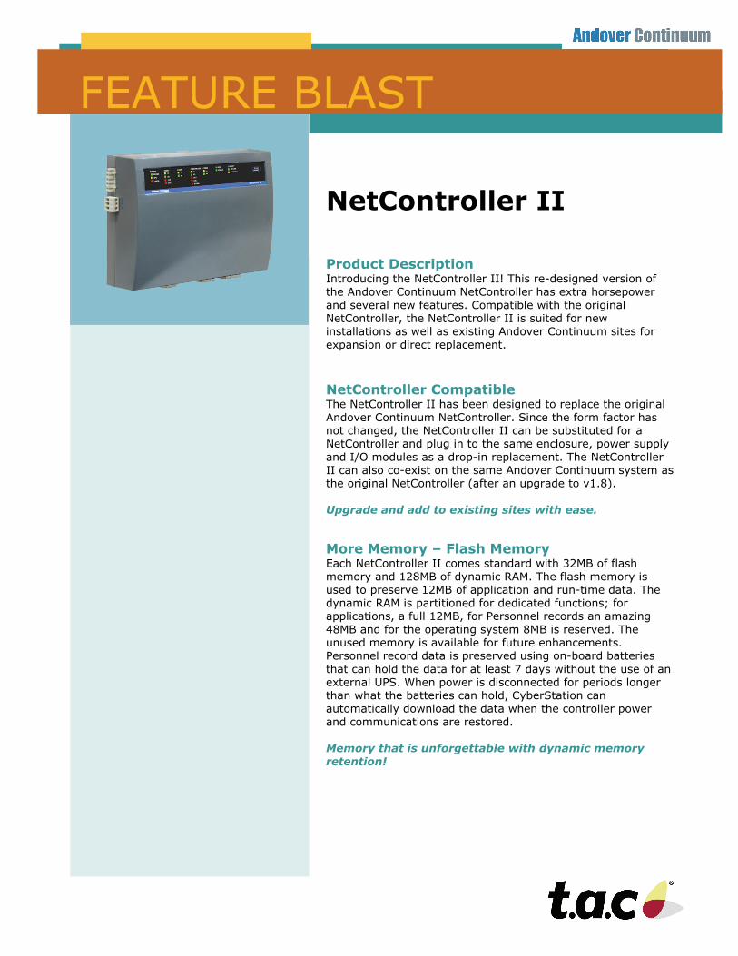
NetController II
Product Description Introducing the NetController II! This re-designed version of the Andover Continuum NetController has extra horsepower and several new features. Compatible with the original NetController, the NetController II is suited for new installations as well as existing Andover Continuum sites for expansion or direct replacement.
NetController Compatible The NetController II has been designed to replace the original Andover Continuum NetController. Since the form factor has not changed, the NetController II can be substituted for a NetController and plug in to the same enclosure, power supply and I/O modules as a drop-in replacement. The NetController II can also co-exist on the same Andover Continuum system as the original NetController (after an upgrade to v1.8). Upgrade and add to existing sites with ease.
More Memory – Flash Memory Each NetController II comes standard with 32MB of flash memory and 128MB of dynamic RAM. The flash memory is used to preserve 12MB of application and run-time data. The dynamic RAM is partitioned for dedicated functions; for applications, a full 12MB, for Personnel records an amazing 48MB and for the operating system 8MB is reserved. The unused memory is available for future enhancements. Personnel record data is preserved using on-board batteries that can hold the data for at least 7 days without the use of an external UPS. When power is disconnected for periods longer than what the batteries can hold, CyberStation can automatically download the data when the controller power and communications are restored. Memory that is unforgettable with dynamic memory retention!
Store 218k to 480k Personnel Records The NetController II is perfect for large systems. A controller servicing up to 8 areas can hold 480,000 personnel records and a controller with 32 areas will store 218,000 records. Which such a large local storage capacity, access decisions can be made swiftly without waiting for validation by a remote server. Store Personnel Records locally!
AC/DC Power Options The NetController II still supports the NetController power supplies (including UPS models) that power the controller and attached I/O modules with DC voltage. Additionally, the NetController II now supports 24 VAC power sources allowing low cost AC transformers to power the controller for non-I/O module applications. Power the NetController II with low cost 24 VAC power supplies
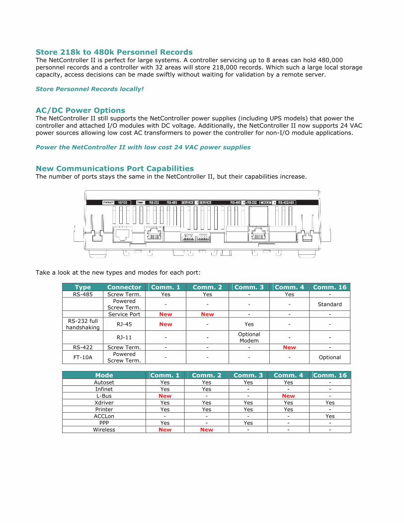
New Communications Port Capabilities The number of ports stays the same in the NetController II, but their capabilities increase.
Take a look at the new types and modes for each port:
Type Connector Comm. 1 Comm. 2 Comm. 3 Comm. 4 Comm. 16 RS-485 Screw Term. Yes Yes - Yes -
Powered
Screw Term. - - - - Standard
Service Port New New - - - RS-232 full
handshaking RJ-45 New - Yes - -
RJ-11 - - Optional Modem
- -
RS-422 Screw Term. - - - New -
FT-10A Powered
Screw Term. - - - - Optional
Mode Comm. 1 Comm. 2 Comm. 3 Comm. 4 Comm. 16 Autoset Yes Yes Yes Yes - Infinet Yes Yes - - - L-Bus New - - New -
Xdriver Yes Yes Yes Yes Yes Printer Yes Yes Yes Yes - ACCLon - - - - Yes
PPP Yes - Yes - - Wireless New New - - -
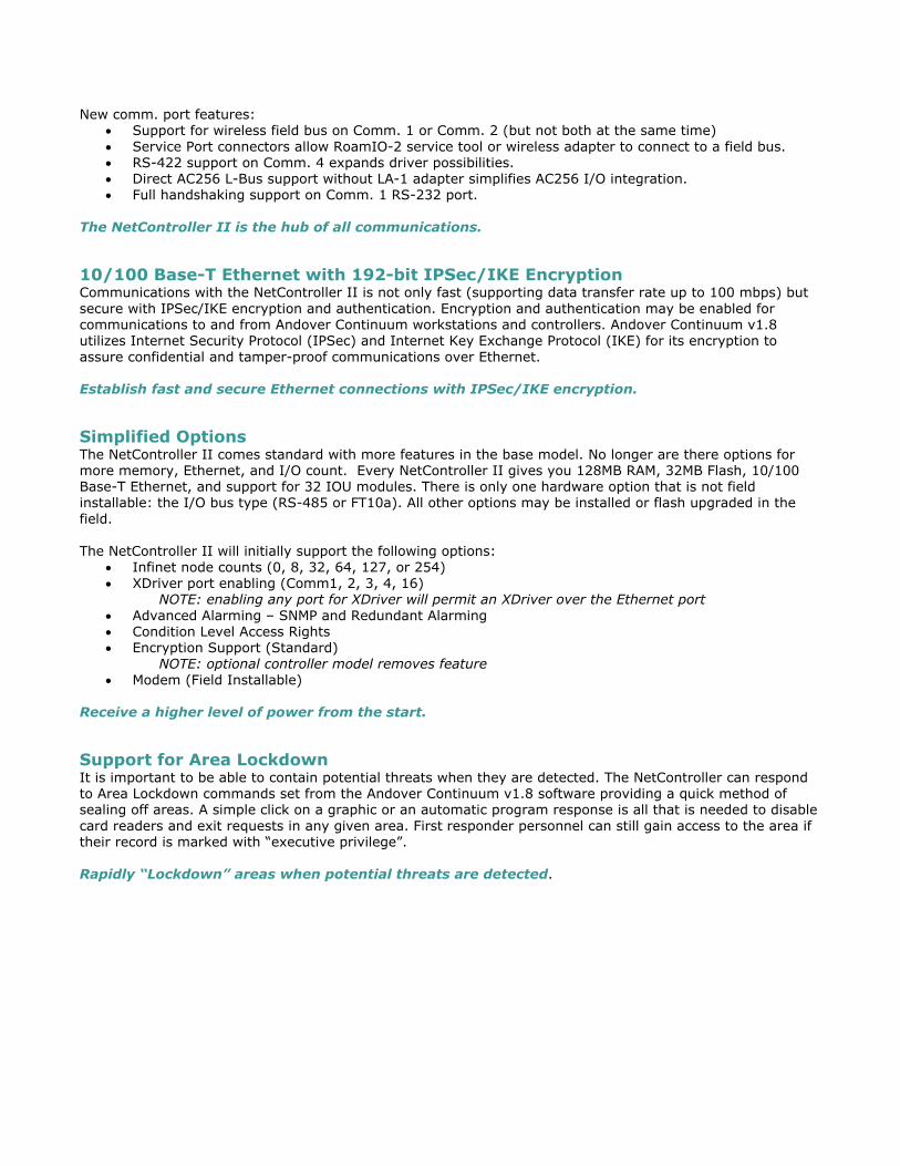
New comm. port features: • Support for wireless field bus on Comm. 1 or Comm. 2 (but not both at the same time) • Service Port connectors allow RoamIO-2 service tool or wireless adapter to connect to a field bus. • RS-422 support on Comm. 4 expands driver possibilities. • Direct AC256 L-Bus support without LA-1 adapter simplifies AC256 I/O integration. • Full handshaking support on Comm. 1 RS-232 port.
The NetController II is the hub of all communications.
10/100 Base-T Ethernet with 192-bit IPSec/IKE Encryption Communications with the NetController II is not only fast (supporting data transfer rate up to 100 mbps) but secure with IPSec/IKE encryption and authentication. Encryption and authentication may be enabled for communications to and from Andover Continuum workstations and controllers. Andover Continuum v1.8 utilizes Internet Security Protocol (IPSec) and Internet Key Exchange Protocol (IKE) for its encryption to assure confidential and tamper-proof communications over Ethernet. Establish fast and secure Ethernet connections with IPSec/IKE encryption.
Simplified Options The NetController II comes standard with more features in the base model. No longer are there options for more memory, Ethernet, and I/O count. Every NetController II gives you 128MB RAM, 32MB Flash, 10/100 Base-T Ethernet, and support for 32 IOU modules. There is only one hardware option that is not field installable: the I/O bus type (RS-485 or FT10a). All other options may be installed or flash upgraded in the field. The NetController II will initially support the following options:
• Infinet node counts (0, 8, 32, 64, 127, or 254) • XDriver port enabling (Comm1, 2, 3, 4, 16)
NOTE: enabling any port for XDriver will permit an XDriver over the Ethernet port • Advanced Alarming – SNMP and Redundant Alarming • Condition Level Access Rights • Encryption Support (Standard)
NOTE: optional controller model removes feature • Modem (Field Installable)
Receive a higher level of power from the start.
Support for Area Lockdown It is important to be able to contain potential threats when they are detected. The NetController can respond to Area Lockdown commands set from the Andover Continuum v1.8 software providing a quick method of sealing off areas. A simple click on a graphic or an automatic program response is all that is needed to disable card readers and exit requests in any given area. First responder personnel can still gain access to the area if their record is marked with “executive privilege”.
Rapidly “Lockdown” areas when potential threats are detected.
Conditional “Threat” Level-based Access Rights The NetController II can adapt access rights to a change in condition or “threat” levels as the U.S. Department of Homeland Security refers to them. Each personnel record can now be assigned a clearance level for each area to which they have access. When the condition is more severe than the person’s clearance level, access is automatically denied. The Condition Level may be set manually through CyberStation v1.8 or automatically through a program. A program can even be written to monitor national threat levels and adjust Andover Continuum Condition Levels accordingly.
Although the U.S. government only calls for five condition levels of threat, v1.8 is capable of assigning up to 255 condition levels for local security needs. Automatically adjust Access Rights when conditions and threat levels change.
Support for HID Corporate-1000 Cards The NetController II now supports HID’s Corporate-1000 cards. The Corporate-1000 standard permits organizations to register with HID to purchase access cards with a single site code that will allow up to one million cards for that one site code. This feature is particularly attractive to enterprise level customers who have multiple sites. Reduce your site codes to one!
Web Server and Configuration Web Pages Like the original NetController, the NetController II supports the hosting of custom web pages directly from the controller. The NetController II has replaced the terminal interface of the NetController with configuration web pages allowing for easy configuration of controller settings such as the IP address and encryption settings. Initialize the NetController II from a web page.
Modbus XDriver Support The NetController II is initially available with XDriver support for Modbus communications. The Modbus/RTU, Modbus/TCP and Plain English Filter drivers have been recompiled and tested for the new hardware. In the future, other drivers may be made available for the NetController II. Link Andover Continuum with Modbus equipment.
CyberStation support The NetController II requires that all CyberStation and web.Client products are at v1.8 or greater. If you are replacing a NetController with a NetController II, CyberStation will perform a one-time, one-way conversion to the new model number creating the NetController specific objects in the process. Simply upgrade to the future.
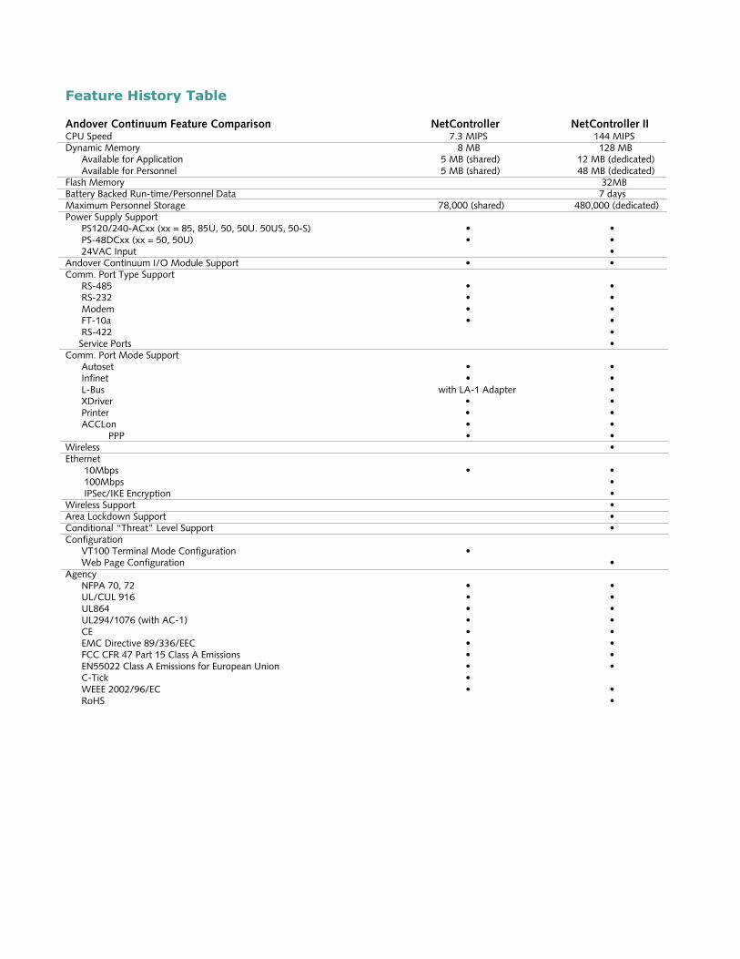
Feature History Table Andover Continuum Feature Comparison NetController NetController II CPU Speed 7.3 MIPS 144 MIPS Dynamic Memory 8 MB 128 MB Available for Application 5 MB (shared) 12 MB (dedicated) Available for Personnel 5 MB (shared) 48 MB (dedicated) Flash Memory 32MB Battery Backed Run-time/Personnel Data 7 days Maximum Personnel Storage 78,000 (shared) 480,000 (dedicated) Power Supply Support PS120/240-ACxx (xx = 85, 85U, 50, 50U. 50US, 50-S) • • PS-48DCxx (xx = 50, 50U) • • 24VAC Input • Andover Continuum I/O Module Support • • Comm. Port Type Support RS-485 • • RS-232 • • Modem • • FT-10a • • RS-422 • Service Ports • Comm. Port Mode Support Autoset • • Infinet • • L-Bus with LA-1 Adapter • XDriver • • Printer • • ACCLon • • PPP • • Wireless • Ethernet 10Mbps • • 100Mbps • IPSec/IKE Encryption • Wireless Support • Area Lockdown Support • Conditional “Threat” Level Support • Configuration VT100 Terminal Mode Configuration • Web Page Configuration • Agency NFPA 70, 72 • • UL/CUL 916 • • UL864 • • UL294/1076 (with AC-1) • • CE • • EMC Directive 89/336/EEC • • FCC CFR 47 Part 15 Class A Emissions • • EN55022 Class A Emissions for European Union • • C-Tick • WEEE 2002/96/EC • • RoHS •
1
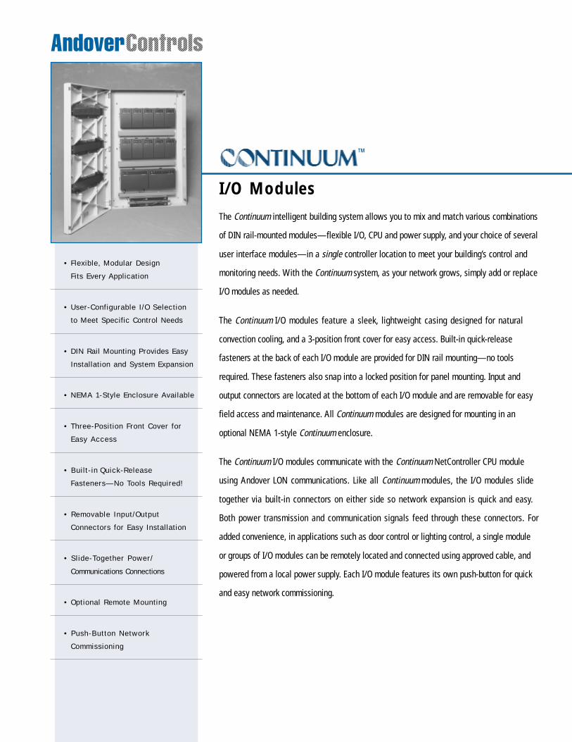
The Continuum intelligent building system allows you to mix and match various combinations
of DIN rail-mounted modules—flexible I/O, CPU and power supply, and your choice of several
user interface modules—in a single controller location to meet your building’s control and
monitoring needs. With the Continuum system, as your network grows, simply add or replace
I/O modules as needed.
The Continuum I/O modules feature a sleek, lightweight casing designed for natural
convection cooling, and a 3-position front cover for easy access. Built-in quick-release
fasteners at the back of each I/O module are provided for DIN rail mounting—no tools
required. These fasteners also snap into a locked position for panel mounting. Input and
output connectors are located at the bottom of each I/O module and are removable for easy
field access and maintenance. All Continuum modules are designed for mounting in an
optional NEMA 1-style Continuum enclosure.
The Continuum I/O modules communicate with the Continuum NetController CPU module
using Andover LON communications. Like all Continuum modules, the I/O modules slide
together via built-in connectors on either side so network expansion is quick and easy.
Both power transmission and communication signals feed through these connectors. For
added convenience, in applications such as door control or lighting control, a single module
or groups of I/O modules can be remotely located and connected using approved cable, and
powered from a local power supply. Each I/O module features its own push-button for quick
and easy network commissioning.
I/O Modules
ª
• Flexible, Modular Design
Fits Every Application
• User-Configurable I/O Selection
to Meet Specific Control Needs
• DIN Rail Mounting Provides Easy
Installation and System Expansion
• NEMA 1-Style Enclosure Available
• Three-Posit ion Front Cover for
Easy Access
• Bui l t- in Quick-Release
Fasteners—No Tools Required!
• Removable Input/Output
Connectors for Easy Installation
• Sl ide-Together Power/
Communications Connections
• Optional Remote Mounting
• Push-Button Network
Commissioning
2
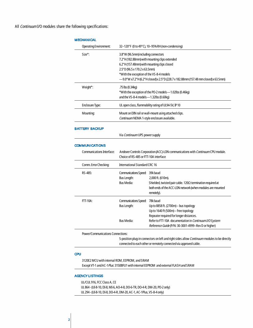
All Continuum I/O modules share the following specifications:
MECHANICALMECHANICALMECHANICALMECHANICALMECHANICAL
Operating Environment: 32–120°F (0 to 49°C), 10–95%RH (non-condensing)
Size*: 3.8”W (96.5mm) including connectors7.2”H (182.88mm) with mounting clips extended6.2”H (157.48mm) with mounting clips closed2.5”D (96.5 x 170.2 x 63.5mm)*With the exception of the VS-8-4 models—9.0”W x7.2”H (6.2”H closed) x 2.5”D (228.7 x 182.88mm (157.48 mm closed) x 63.5mm)
Weight*: .75 lbs (0.34kg)*With the exception of the PO-2 models—1.02lbs (0.46kg)and the VS-8-4 models—1.32lbs (0.60kg)
Enclosure Type: UL open class, flammability rating of UL94-5V, IP 10
Mounting: Mount on DIN rail or wall-mount using attached clips.Continuum NEMA 1-style enclosure available.
B AB AB AB AB ATTERY BACKUPTTERY BACKUPTTERY BACKUPTTERY BACKUPTTERY BACKUP
Via Continuum UPS power supply
COMMUNICACOMMUNICACOMMUNICACOMMUNICACOMMUNICATIONSTIONSTIONSTIONSTIONS
Communications Interface: Andover Controls Corporation (ACC)-LON communications with Continuum CPU module.Choice of RS-485 or FTT-10A interface
Comm. Error Checking: International Standard CRC 16
RS-485: Communications Speed: 39k baudBus Length: 2,000 ft. (610m).Bus Media: Shielded, twisted pair cable. 120Ω termination required at
both ends of the ACC-LON network (when modules are mountedremotely).
FTT-10A: Communications Speed: 78k baudBus Length: Up to 8858 ft. (2700m) – bus topology
Up to 1640 ft (500m) – free topologyRepeater required for longer distances.
Bus Media: Refer to FTT-10A documentation in Continuum I/O SystemReference Guide (P/N: 30-3001-4999--Rev D or higher)
Power/Communications Connections:5-position plug-in connectors on left and right sides allow Continuum modules to be directlyconnected to each other or remotely connected via approved cable.
CPUCPUCPUCPUCPU
3120E2 MCU with internal ROM, EEPROM, and SRAMExcept VT-1 and AC-1Plus: 3150BFU1 with internal EEPROM and external FLASH and SRAM
AGENCY LISTINGSAGENCY LISTINGSAGENCY LISTINGSAGENCY LISTINGSAGENCY LISTINGS
UL/CUL 916, FCC Class A, CEUL 864 - (UI-8-10, DI-8, MI-6, AO-4-8, DO-6-TR, DO-4-R, DM-20, PO-2 only)UL 294 - (UI-8-10, DI-8, DO-4-R, DM-20, AC-1, AC-1Plus, VS-8-4 only)
4
UI-8-10I / O M O D U L EI / O M O D U L EI / O M O D U L EI / O M O D U L EI / O M O D U L E
S P E C I F I C A T I O N SS P E C I F I C A T I O N SS P E C I F I C A T I O N SS P E C I F I C A T I O N SS P E C I F I C A T I O N S
M O D E L SM O D E L SM O D E L SM O D E L SM O D E L S
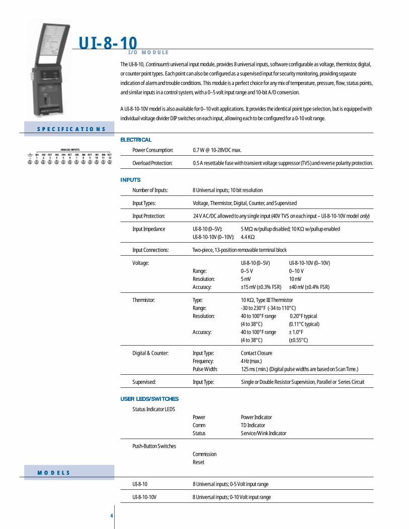
The UI-8-10, Continuum’s universal input module, provides 8 universal inputs, software configurable as voltage, thermistor, digital,
or counter point types. Each point can also be configured as a supervised input for security monitoring, providing separate
indication of alarm and trouble conditions. This module is a perfect choice for any mix of temperature, pressure, flow, status points,
and similar inputs in a control system, with a 0–5 volt input range and 10-bit A/D conversion.
A UI-8-10-10V model is also available for 0–10 volt applications. It provides the identical point type selection, but is equipped with
individual voltage divider DIP switches on each input, allowing each to be configured for a 0-10 volt range.
ELECTRICALELECTRICALELECTRICALELECTRICALELECTRICAL
Power Consumption: 0.7 W @ 10-28VDC max.
Overload Protection: 0.5 A resettable fuse with transient voltage suppressor (TVS) and reverse polarity protection.
INPUTSINPUTSINPUTSINPUTSINPUTS
Number of Inputs: 8 Universal inputs; 10 bit resolution
Input Types: Voltage, Thermistor, Digital, Counter, and Supervised
Input Protection: 24 V AC/DC allowed to any single input (40V TVS on each input – UI-8-10-10V model only)
Input Impedance UI-8-10 (0–5V): 5 MΩ w/pullup disabled; 10 KΩ w/pullup enabledUI-8-10-10V (0–10V): 4.4 KΩ
Input Connections: Two-piece, 13-position removable terminal block
Voltage: UI-8-10 (0–5V) UI-8-10-10V (0–10V)Range: 0–5 V 0–10 VResolution: 5 mV 10 mVAccuracy: ±15 mV (±0.3% FSR) ±40 mV (±0.4% FSR)
Thermistor: Type: 10 KΩ, Type III ThermistorRange: -30 to 230°F (-34 to 110°C)Resolution: 40 to 100°F range 0.20°F typical
(4 to 38°C) (0.11°C typical)Accuracy: 40 to 100°F range ± 1.0°F
(4 to 38°C) (±0.55°C)
Digital & Counter: Input Type: Contact ClosureFrequency: 4 Hz (max.)Pulse Width: 125 ms ( min.) (Digital pulse widths are based on Scan Time.)
Supervised: Input Type: Single or Double Resistor Supervision, Parallel or Series Circuit
USER LEDS/SWITCHESUSER LEDS/SWITCHESUSER LEDS/SWITCHESUSER LEDS/SWITCHESUSER LEDS/SWITCHES
Status Indicator LEDSPower Power IndicatorComm TD IndicatorStatus Service/Wink Indicator
Push-Button SwitchesCommissionReset
UI-8-10 8 Universal inputs; 0-5 Volt input range
UI-8-10-10V 8 Universal inputs; 0-10 Volt input range
5
DI-8I/O MODULEI/O MODULEI/O MODULEI/O MODULEI/O MODULE
S P E C I F I C A T I O N SS P E C I F I C A T I O N SS P E C I F I C A T I O N SS P E C I F I C A T I O N SS P E C I F I C A T I O N S
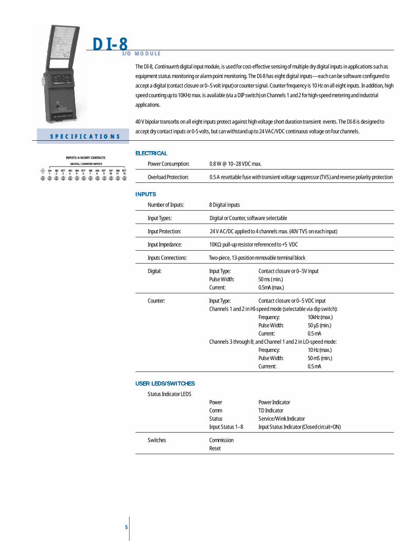
The DI-8, Continuum’s digital input module, is used for cost-effective sensing of multiple dry digital inputs in applications such as
equipment status monitoring or alarm point monitoring. The DI-8 has eight digital inputs—each can be software configured to
accept a digital (contact closure or 0–5 volt input) or counter signal. Counter frequency is 10 Hz on all eight inputs. In addition, high
speed counting up to 10KHz max. is available (via a DIP switch) on Channels 1 and 2 for high-speed metering and industrial
applications.
40 V bipolar transorbs on all eight inputs protect against high voltage short duration transient events. The DI-8 is designed to
accept dry contact inputs or 0-5 volts, but can withstand up to 24 VAC/VDC continuous voltage on four channels.
ELECTRICALELECTRICALELECTRICALELECTRICALELECTRICAL
Power Consumption: 0.8 W @ 10–28 VDC max.
Overload Protection: 0.5 A resettable fuse with transient voltage suppressor (TVS) and reverse polarity protection
INPUTSINPUTSINPUTSINPUTSINPUTS
Number of Inputs: 8 Digital inputs
Input Types: Digital or Counter, software selectable
Input Protection: 24 V AC/DC applied to 4 channels max. (40V TVS on each input)
Input Impedance: 10KΩ pull-up resistor referenced to +5 VDC
Inputs Connections: Two-piece, 13-position removable terminal block
Digital: Input Type: Contact closure or 0–5V inputPulse Width: 50 ms ( min.)Current: 0.5mA (max.)
Counter: Input Type: Contact closure or 0–5 VDC inputChannels 1 and 2 in HI-speed mode (selectable via dip switch):
Frequency: 10kHz (max.)Pulse Width: 50 µS (min.)Current: 0.5 mA
Channels 3 through 8; and Channel 1 and 2 in LO-speed mode:Frequency: 10 Hz (max.)Pulse Width: 50 mS (min.)Currrent: 0.5 mA
USER LEDS/SWITCHESUSER LEDS/SWITCHESUSER LEDS/SWITCHESUSER LEDS/SWITCHESUSER LEDS/SWITCHES
Status Indicator LEDSPower Power IndicatorComm TD IndicatorStatus Service/Wink IndicatorInput Status 1–8 Input Status Indicator (Closed circuit=ON)
Switches CommissionReset
6
DI-6-ACI / O M O D U L EI / O M O D U L EI / O M O D U L EI / O M O D U L EI / O M O D U L E
S P E C I F I C A T I O N SS P E C I F I C A T I O N SS P E C I F I C A T I O N SS P E C I F I C A T I O N SS P E C I F I C A T I O N S
M O D E L SM O D E L SM O D E L SM O D E L SM O D E L S
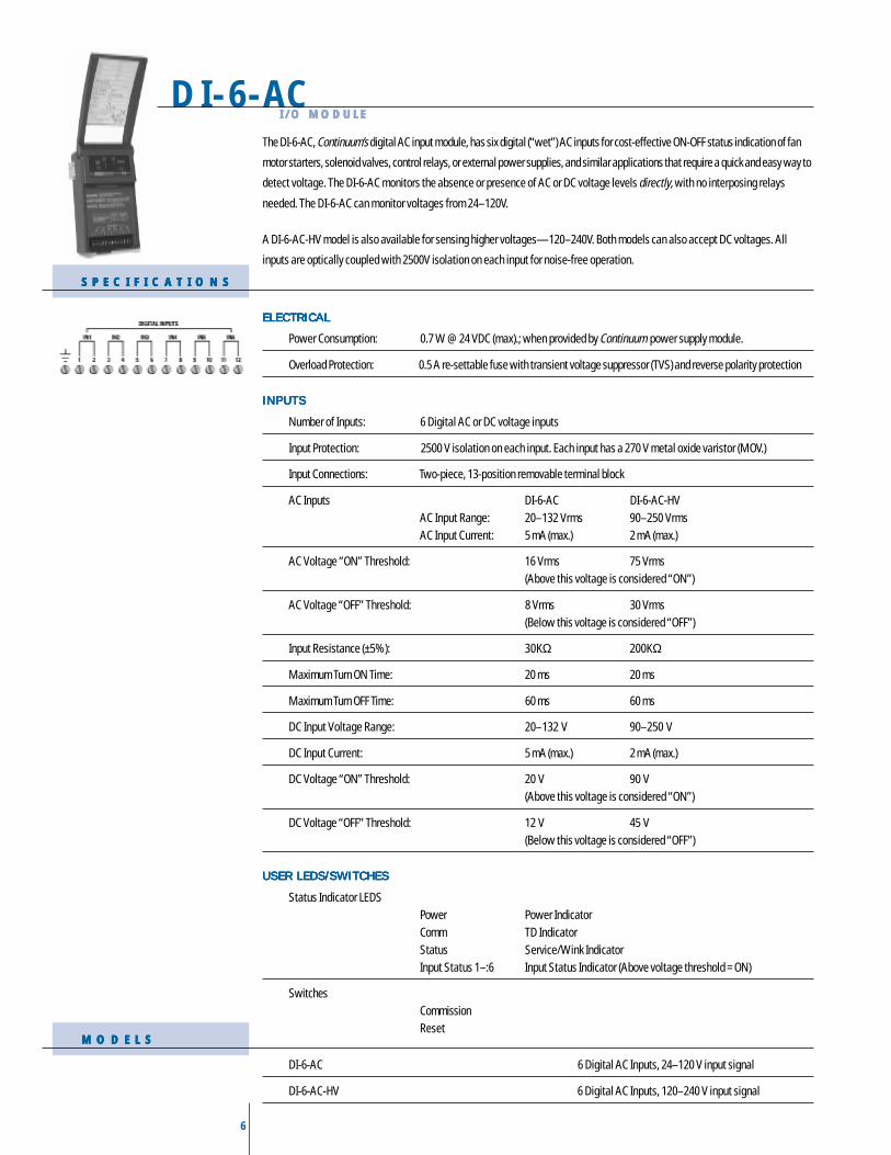
The DI-6-AC, Continuum’s digital AC input module, has six digital (“wet”) AC inputs for cost-effective ON-OFF status indication of fan
motor starters, solenoid valves, control relays, or external power supplies, and similar applications that require a quick and easy way to
detect voltage. The DI-6-AC monitors the absence or presence of AC or DC voltage levels directly, with no interposing relays
needed. The DI-6-AC can monitor voltages from 24–120V.
A DI-6-AC-HV model is also available for sensing higher voltages—120–240V. Both models can also accept DC voltages. All
inputs are optically coupled with 2500V isolation on each input for noise-free operation.
ELECTRICALELECTRICALELECTRICALELECTRICALELECTRICAL
Power Consumption: 0.7 W @ 24 VDC (max).; when provided by Continuum power supply module.
Overload Protection: 0.5 A re-settable fuse with transient voltage suppressor (TVS) and reverse polarity protection
INPUTSINPUTSINPUTSINPUTSINPUTS
Number of Inputs: 6 Digital AC or DC voltage inputs
Input Protection: 2500 V isolation on each input. Each input has a 270 V metal oxide varistor (MOV.)
Input Connections: Two-piece, 13-position removable terminal block
AC Inputs DI-6-AC DI-6-AC-HVAC Input Range: 20–132 Vrms 90–250 VrmsAC Input Current: 5 mA (max.) 2 mA (max.)
AC Voltage “ON” Threshold: 16 Vrms 75 Vrms(Above this voltage is considered “ON”)
AC Voltage “OFF” Threshold: 8 Vrms 30 Vrms(Below this voltage is considered “OFF”)
Input Resistance (±5%): 30KΩ 200KΩ
Maximum Turn ON Time: 20 ms 20 ms
Maximum Turn OFF Time: 60 ms 60 ms
DC Input Voltage Range: 20–132 V 90–250 V
DC Input Current: 5 mA (max.) 2 mA (max.)
DC Voltage “ON” Threshold: 20 V 90 V(Above this voltage is considered “ON”)
DC Voltage “OFF” Threshold: 12 V 45 V(Below this voltage is considered “OFF”)
USER LEDS/SWITCHESUSER LEDS/SWITCHESUSER LEDS/SWITCHESUSER LEDS/SWITCHESUSER LEDS/SWITCHES
Status Indicator LEDSPower Power IndicatorComm TD IndicatorStatus Service/Wink IndicatorInput Status 1–:6 Input Status Indicator (Above voltage threshold = ON)
SwitchesCommissionReset
DI-6-AC 6 Digital AC Inputs, 24–120 V input signal
DI-6-AC-HV 6 Digital AC Inputs, 120–240 V input signal
7
MI-6I/O MODULEI/O MODULEI/O MODULEI/O MODULEI/O MODULE
S P E C I F I C A T I O N SS P E C I F I C A T I O N SS P E C I F I C A T I O N SS P E C I F I C A T I O N SS P E C I F I C A T I O N S
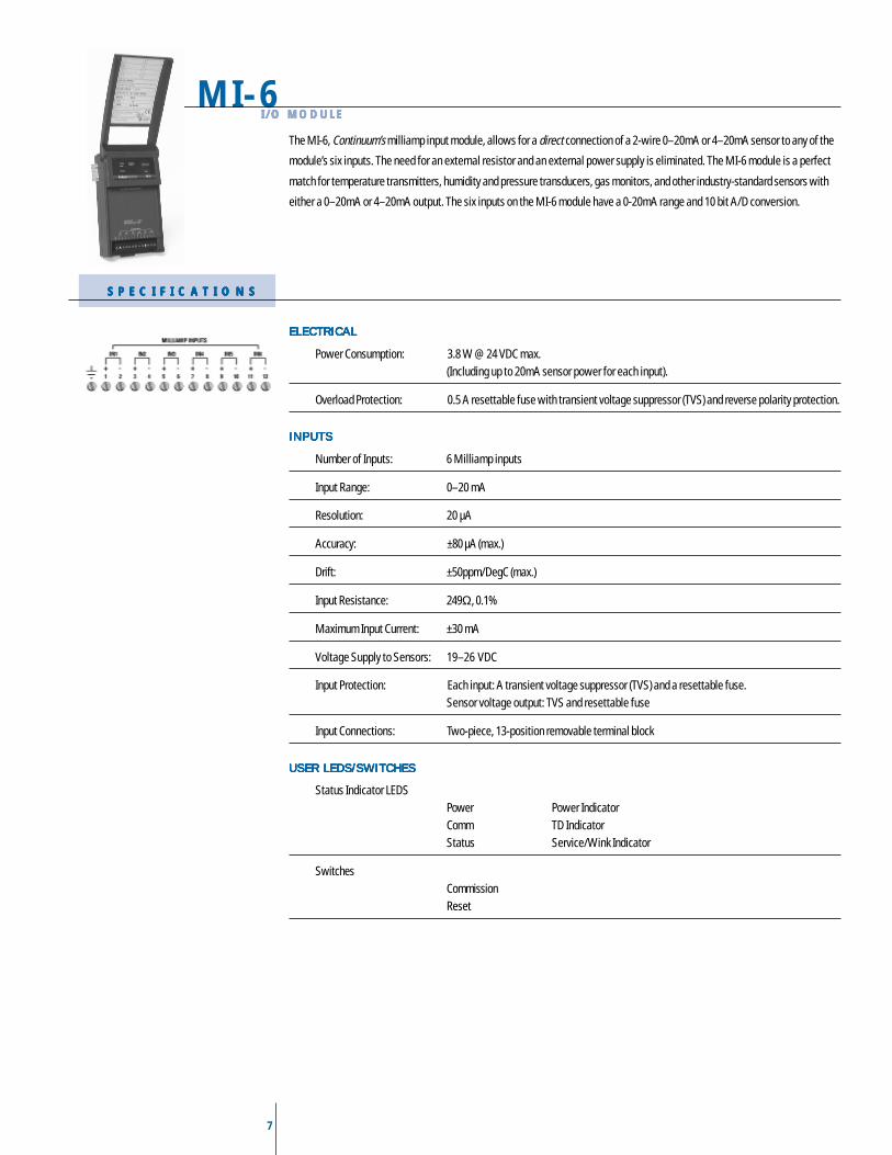
The MI-6, Continuum’s milliamp input module, allows for a direct connection of a 2-wire 0–20mA or 4–20mA sensor to any of the
module’s six inputs. The need for an external resistor and an external power supply is eliminated. The MI-6 module is a perfect
match for temperature transmitters, humidity and pressure transducers, gas monitors, and other industry-standard sensors with
either a 0–20mA or 4–20mA output. The six inputs on the MI-6 module have a 0-20mA range and 10 bit A/D conversion.
ELECTRICALELECTRICALELECTRICALELECTRICALELECTRICAL
Power Consumption: 3.8 W @ 24 VDC max.(Including up to 20mA sensor power for each input).
Overload Protection: 0.5 A resettable fuse with transient voltage suppressor (TVS) and reverse polarity protection.
INPUTSINPUTSINPUTSINPUTSINPUTS
Number of Inputs: 6 Milliamp inputs
Input Range: 0–20 mA
Resolution: 20 µA
Accuracy: ±80 µA (max.)
Drift: ±50ppm/DegC (max.)
Input Resistance: 249Ω, 0.1%
Maximum Input Current: ±30 mA
Voltage Supply to Sensors: 19–26 VDC
Input Protection: Each input: A transient voltage suppressor (TVS) and a resettable fuse.Sensor voltage output: TVS and resettable fuse
Input Connections: Two-piece, 13-position removable terminal block
USER LEDS/SWITCHESUSER LEDS/SWITCHESUSER LEDS/SWITCHESUSER LEDS/SWITCHESUSER LEDS/SWITCHES
Status Indicator LEDSPower Power IndicatorComm TD IndicatorStatus Service/Wink Indicator
SwitchesCommissionReset
8
AO-4-8I / O M O D U L EI / O M O D U L EI / O M O D U L EI / O M O D U L EI / O M O D U L E
S P E C I F I C A T I O N SS P E C I F I C A T I O N SS P E C I F I C A T I O N SS P E C I F I C A T I O N SS P E C I F I C A T I O N S
M O D E L SM O D E L SM O D E L SM O D E L SM O D E L S
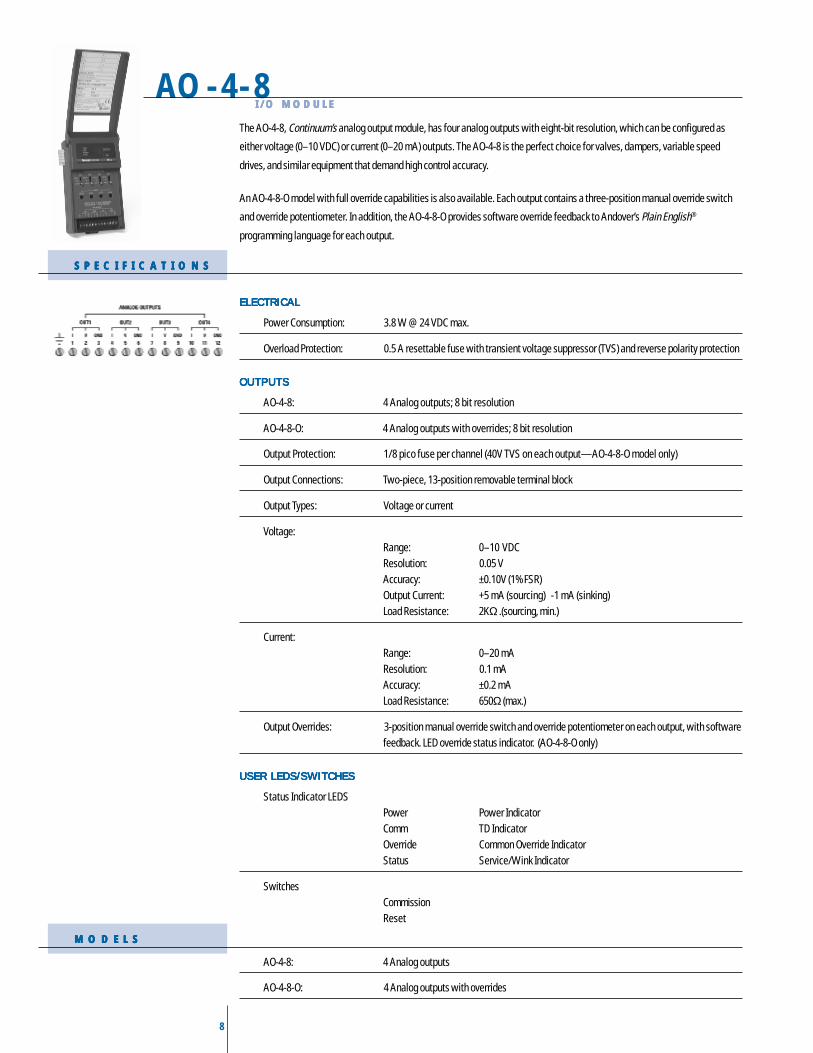
The AO-4-8, Continuum’s analog output module, has four analog outputs with eight-bit resolution, which can be configured as
either voltage (0–10 VDC) or current (0–20 mA) outputs. The AO-4-8 is the perfect choice for valves, dampers, variable speed
drives, and similar equipment that demand high control accuracy.
An AO-4-8-O model with full override capabilities is also available. Each output contains a three-position manual override switch
and override potentiometer. In addition, the AO-4-8-O provides software override feedback to Andover’s Plain English®
programming language for each output.
ELECTRICALELECTRICALELECTRICALELECTRICALELECTRICAL
Power Consumption: 3.8 W @ 24 VDC max.
Overload Protection: 0.5 A resettable fuse with transient voltage suppressor (TVS) and reverse polarity protection
OUTPUTSOUTPUTSOUTPUTSOUTPUTSOUTPUTS
AO-4-8: 4 Analog outputs; 8 bit resolution
AO-4-8-O: 4 Analog outputs with overrides; 8 bit resolution
Output Protection: 1/8 pico fuse per channel (40V TVS on each output—AO-4-8-O model only)
Output Connections: Two-piece, 13-position removable terminal block
Output Types: Voltage or current
Voltage:Range: 0–10 VDCResolution: 0.05 VAccuracy: ±0.10V (1%FSR)Output Current: +5 mA (sourcing) -1 mA (sinking)Load Resistance: 2KΩ .(sourcing, min.)
Current:Range: 0–20 mAResolution: 0.1 mAAccuracy: ±0.2 mALoad Resistance: 650Ω (max.)
Output Overrides: 3-position manual override switch and override potentiometer on each output, with softwarefeedback. LED override status indicator. (AO-4-8-O only)
USER LEDS/SWITCHESUSER LEDS/SWITCHESUSER LEDS/SWITCHESUSER LEDS/SWITCHESUSER LEDS/SWITCHES
Status Indicator LEDSPower Power IndicatorComm TD IndicatorOverride Common Override IndicatorStatus Service/Wink Indicator
SwitchesCommissionReset
AO-4-8: 4 Analog outputs
AO-4-8-O: 4 Analog outputs with overrides
9
DO-6-TRI/O MODULEI/O MODULEI/O MODULEI/O MODULEI/O MODULE
S P E C I F I C A T I O N SS P E C I F I C A T I O N SS P E C I F I C A T I O N SS P E C I F I C A T I O N SS P E C I F I C A T I O N S
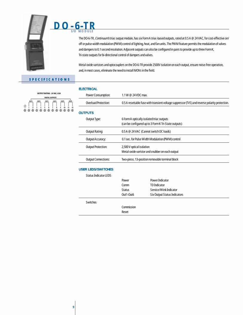
The DO-6-TR, Continuum’s triac output module, has six Form A triac-based outputs, rated at 0.5 A @ 24 VAC, for cost-effective on/
off or pulse-width modulation (PWM) control of lighting, heat, and fan units. The PWM feature permits the modulation of valves
and dampers to 0.1 second resolution. Adjacent outputs can also be configured in pairs to provide up to three Form K,
Tri-state outputs for bi-directional control of dampers and valves.
Metal oxide varistors and optocouplers on the DO-6-TR provide 2500V isolation on each output, ensure noise-free operation,
and, in most cases, eliminate the need to install MOVs in the field.
ELECTRICALELECTRICALELECTRICALELECTRICALELECTRICAL
Power Consumption: 1.1 W @ 24 VDC max.
Overload Protection: 0.5 A resettable fuse with transient voltage suppressor (TVS) and reverse polarity protection.
OUTPUTSOUTPUTSOUTPUTSOUTPUTSOUTPUTS
Output Type: 6 Form A optically isolated triac outputs(can be configured up to 3 Form K Tri-State outputs)
Output Rating: 0.5 A @ 24 VAC (Cannot switch DC loads)
Output Accuracy: 0.1 sec. for Pulse Width Modulation (PWM) control
Output Protection: 2,500 V optical isolationMetal oxide varistor and snubber on each output
Output Connections: Two-piece, 13-position removable terminal block
USER LEDS/SWITCHESUSER LEDS/SWITCHESUSER LEDS/SWITCHESUSER LEDS/SWITCHESUSER LEDS/SWITCHES
Status Indicator LEDSPower Power IndicatorComm TD IndicatorStatus Service/Wink IndicatorOut1-Out6 Six Output Status Indicators
SwitchesCommissionReset
10
DO-4-RI / O M O D U L EI / O M O D U L EI / O M O D U L EI / O M O D U L EI / O M O D U L E
S P E C I F I C A T I O N SS P E C I F I C A T I O N SS P E C I F I C A T I O N SS P E C I F I C A T I O N SS P E C I F I C A T I O N S
M O D E L SM O D E L SM O D E L SM O D E L SM O D E L S
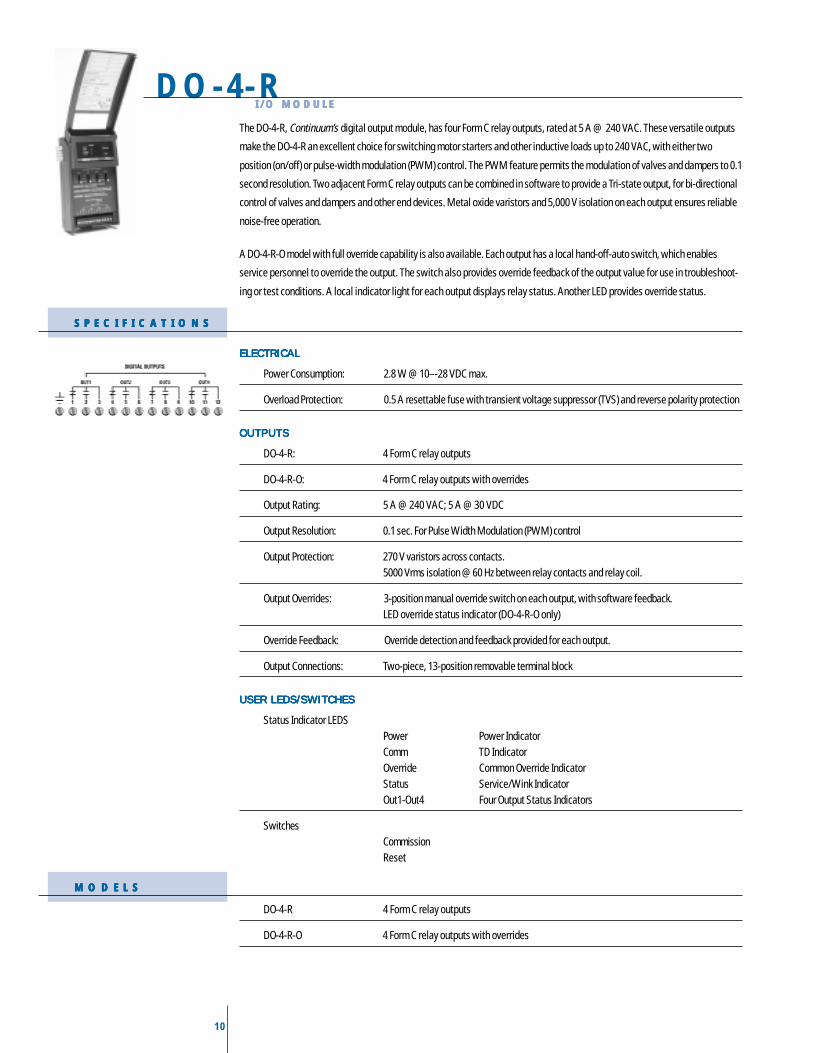
The DO-4-R, Continuum’s digital output module, has four Form C relay outputs, rated at 5 A @ 240 VAC. These versatile outputs
make the DO-4-R an excellent choice for switching motor starters and other inductive loads up to 240 VAC, with either two
position (on/off) or pulse-width modulation (PWM) control. The PWM feature permits the modulation of valves and dampers to 0.1
second resolution. Two adjacent Form C relay outputs can be combined in software to provide a Tri-state output, for bi-directional
control of valves and dampers and other end devices. Metal oxide varistors and 5,000 V isolation on each output ensures reliable
noise-free operation.
A DO-4-R-O model with full override capability is also available. Each output has a local hand-off-auto switch, which enables
service personnel to override the output. The switch also provides override feedback of the output value for use in troubleshoot-
ing or test conditions. A local indicator light for each output displays relay status. Another LED provides override status.
ELECTRICALELECTRICALELECTRICALELECTRICALELECTRICAL
Power Consumption: 2.8 W @ 10–-28 VDC max.
Overload Protection: 0.5 A resettable fuse with transient voltage suppressor (TVS) and reverse polarity protection
OUTPUTSOUTPUTSOUTPUTSOUTPUTSOUTPUTS
DO-4-R: 4 Form C relay outputs
DO-4-R-O: 4 Form C relay outputs with overrides
Output Rating: 5 A @ 240 VAC; 5 A @ 30 VDC
Output Resolution: 0.1 sec. For Pulse Width Modulation (PWM) control
Output Protection: 270 V varistors across contacts.5000 Vrms isolation @ 60 Hz between relay contacts and relay coil.
Output Overrides: 3-position manual override switch on each output, with software feedback.LED override status indicator (DO-4-R-O only)
Override Feedback: Override detection and feedback provided for each output.
Output Connections: Two-piece, 13-position removable terminal block
USER LEDS/SWITCHESUSER LEDS/SWITCHESUSER LEDS/SWITCHESUSER LEDS/SWITCHESUSER LEDS/SWITCHES
Status Indicator LEDSPower Power IndicatorComm TD IndicatorOverride Common Override IndicatorStatus Service/Wink IndicatorOut1-Out4 Four Output Status Indicators
SwitchesCommissionReset
DO-4-R 4 Form C relay outputs
DO-4-R-O 4 Form C relay outputs with overrides
11
DM-20 I/O MODULE
S P E C I F I C A T I O N SS P E C I F I C A T I O N SS P E C I F I C A T I O N SS P E C I F I C A T I O N SS P E C I F I C A T I O N S
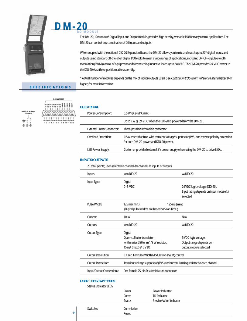
The DM-20, Continuum’s Digital Input and Output module, provides high density, versatile I/O for many control applications.The
DM-20 can control any combination of 20 inputs and outputs.
When coupled with the optional DIO-20 Expansion Board, the DM-20 allows you to mix and match up to 20* digital inputs and
outputs using standard off-the-shelf digital I/O blocks to meet a wide range of applications, including ON-OFF or pulse-width
modulation (PWM) control of equipment and for switching inductive loads up to 240VAC. The DM-20 provides 24 VDC power to
the DIO-20 via a three-position cable assembly.
* Actual number of modules depends on the mix of inputs/outputs used. See Continuum I/O System Reference Manual (Rev D or
higher) for more information.
ELECTRICALELECTRICALELECTRICALELECTRICALELECTRICAL
Power Consumption: 0.5 W @ 24VDC max.
Up to 9 W @ 24 VDC when the DIO-20 is powered from the DM-20 .
External Power Connector: Three-position removable connector
Overload Protection: 0.5 A resettable fuse with transient voltage suppressor (TVS) and reverse polarity protectionfor both DM-20 power and DIO-20 power.
LED Power Supply: Customer-provided external 5 V power supply when using the DM-20 to drive LEDs.
INPUTS/OUTPUTSINPUTS/OUTPUTSINPUTS/OUTPUTSINPUTS/OUTPUTSINPUTS/OUTPUTS
20 total points; user-selectable channel-by-channel as inputs or outputs
Inputs w/o DIO-20 w/DIO-20
Input Type: Digital0–5 VDC 24 VDC logic voltage (DIO-20).
Input rating depends on input module(s)selected
Pulse Width: 125 ms ( min.) 125 ms ( min.) (Digital pulse widths are based on Scan Time.)
Current: 10µA N/A
Outputs w/o DIO-20 w/DIO-20
Output Type: DigitalOpen- collector transistor 5 VDC logic voltage. with series 330 ohm 1/8 W resistor; Output range depends on15 mA (max.) @ 5 V DC output module selected.
Output Resolution: 0.1 sec. For Pulse Width Modulation (PWM) control
Output Protection: Transient voltage suppressor (TVS) and current limiting resistor on each channel.
Input/Output Connections: One female 25-pin D-subminiature connector
USER LEDS/SWITCHESUSER LEDS/SWITCHESUSER LEDS/SWITCHESUSER LEDS/SWITCHESUSER LEDS/SWITCHES
Status Indicator LEDSPower Power IndicatorComm TD IndicatorStatus Service/Wink Indicator
Switches CommissionReset
12
AC-1 I/O MODULE
S P E C I F I C A T I O N SS P E C I F I C A T I O N SS P E C I F I C A T I O N SS P E C I F I C A T I O N SS P E C I F I C A T I O N S
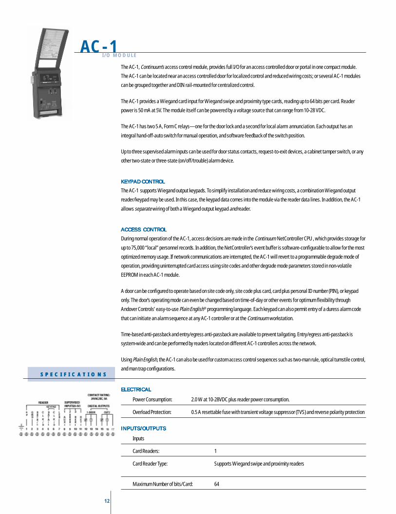
The AC-1, Continuum’s access control module, provides full I/O for an access controlled door or portal in one compact module.
The AC-1 can be located near an access controlled door for localized control and reduced wiring costs; or several AC-1 modules
can be grouped together and DIN rail-mounted for centralized control.
The AC-1 provides a Wiegand card input for Wiegand swipe and proximity type cards, reading up to 64 bits per card. Reader
power is 50 mA at 5V. The module itself can be powered by a voltage source that can range from 10-28 VDC.
The AC-1 has two 5 A, Form C relays—one for the door lock and a second for local alarm annunciation. Each output has an
integral hand-off-auto switch for manual operation, and software feedback of the switch position.
Up to three supervised alarm inputs can be used for door status contacts, request-to-exit devices, a cabinet tamper switch, or any
other two-state or three-state (on/off/trouble) alarm device.
KEYPAD CONTROLKEYPAD CONTROLKEYPAD CONTROLKEYPAD CONTROLKEYPAD CONTROL
The AC-1 supports Wiegand output keypads. To simplify installation and reduce wiring costs, a combination Wiegand output
reader/keypad may be used. In this case, the keypad data comes into the module via the reader data lines. In addition, the AC-1
allows separate wiring of both a Wiegand output keypad and reader.
ACCESS CONTROLACCESS CONTROLACCESS CONTROLACCESS CONTROLACCESS CONTROL
During normal operation of the AC-1, access decisions are made in the Continuum NetController CPU , which provides storage for
up to 75,000 “local” personnel records. In addition, the NetController’s event buffer is software-configurable to allow for the most
optimized memory usage. If network communications are interrupted, the AC-1 will revert to a programmable degrade mode of
operation, providing uninterrupted card access using site codes and other degrade mode parameters stored in non-volatile
EEPROM in each AC-1 module.
A door can be configured to operate based on site code only, site code plus card, card plus personal ID number (PIN), or keypad
only. The door’s operating mode can even be changed based on time-of-day or other events for optimum flexibility through
Andover Controls’ easy-to-use Plain English® programming language. Each keypad can also permit entry of a duress alarm code
that can initiate an alarm sequence at any AC-1 controller or at the Continuum workstation.
Time-based anti-passback and entry/egress anti-passback are available to prevent tailgating. Entry/egress anti-passback is
system-wide and can be performed by readers located on different AC-1 controllers across the network.
Using Plain English, the AC-1 can also be used for custom access control sequences such as two-man rule, optical turnstile control,
and man trap configurations.
ELECTRICALELECTRICALELECTRICALELECTRICALELECTRICAL
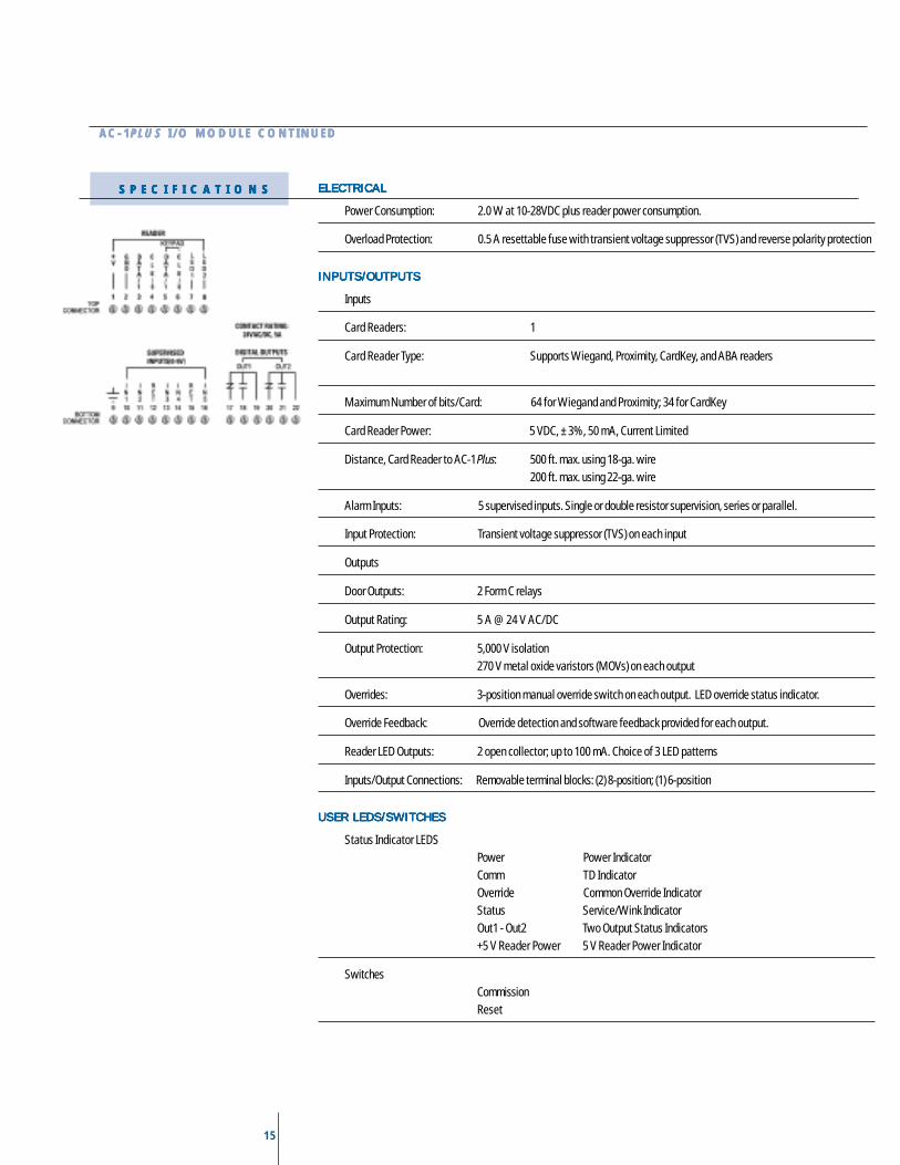
Power Consumption: 2.0 W at 10-28VDC plus reader power consumption.
Overload Protection: 0.5 A resettable fuse with transient voltage suppressor (TVS) and reverse polarity protection
INPUTS/OUTPUTSINPUTS/OUTPUTSINPUTS/OUTPUTSINPUTS/OUTPUTSINPUTS/OUTPUTS
Inputs
Card Readers: 1
Card Reader Type: Supports Wiegand swipe and proximity readers
Maximum Number of bits/Card: 64
13
AC-1 I/O MODULE CONTINUEDAC-1 I/O MODULE CONTINUEDAC-1 I/O MODULE CONTINUEDAC-1 I/O MODULE CONTINUEDAC-1 I/O MODULE CONTINUED
Card Reader Power: 5 VDC, ± 3%, 50 mA, Current Limited
Distance, Card Reader to AC-1: 500 ft. max. using 18-ga. wire200 ft. max. using 22-ga. wire
Alarm Inputs: Up to 3 supervised inputs. Single or double resistor supervision, series or parallel.
Input Protection: Transient voltage suppressor (TVS) on each input
Outputs
Door Outputs: 2 Form C relays
Output Rating: 5 A @ 24 V AC/DC
Output Protection: 5,000 V isolation270 V metal oxide varistors (MOVs) on each output
Overrides: 3-position manual override switch on each output for manual control of relay. LED overridestatus indicator.
Override Feedback: Override detection and software feedback provided for each output.
Reader LED Output: Open collector; up to 100 mA.
Inputs/Output Connections: Two-piece, 18-position removable terminal block
USER LEDS/SWITCHESUSER LEDS/SWITCHESUSER LEDS/SWITCHESUSER LEDS/SWITCHESUSER LEDS/SWITCHES
Status Indicator LEDSPower Power IndicatorComm TD IndicatorOverride Common Override IndicatorStatus Service/Wink IndicatorOut1 - Out2 Two Output Status Indicators+5 V Reader Power 5 V Reader Power Indicator
SwitchesCommissionReset
14
AC-1Plus I/O MODULE
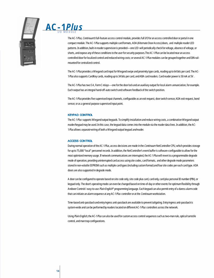
The AC-1Plus, Continuum’s full-feature access control module, provides full I/O for an access controlled door or portal in one
compact module. The AC-1Plus supports multiple card formats, ADA (Alternate Door Access) doors, and multiple reader LED
patterns. In addition, built-in reader supervision is provided—one LED will periodically check for voltage, absence of voltage, or
shorts, and expose any of these conditions to the user for security purposes.The AC-1Plus can be located near an access
controlled door for localized control and reduced wiring costs; or several AC-1Plus modules can be grouped together and DIN rail-
mounted for centralized control.
The AC-1Plus provides a Wiegand card input for Wiegand swipe and proximity type cards, reading up to 64 bits per card. The AC-
1Plus also supports CardKey cards, reading up to 34 bits per card, and ABA card readers. Card reader power is 50 mA at 5V .
The AC-1Plus has two 5 A, Form C relays—one for the door lock and an auxiliary output for local alarm annunciation, for example.
Each output has an integral hand-off-auto switch and software feedback of the switch position.
The AC-1Plus provides five supervised input channels, configurable as an exit request, door switch sensor, ADA exit request, bond
sensor, or as a general purpose supervised input point.
KEYPAD CONTROLKEYPAD CONTROLKEYPAD CONTROLKEYPAD CONTROLKEYPAD CONTROL
The AC-1Plus supports Wiegand output keypads. To simplify installation and reduce wiring costs, a combination Wiegand output
reader/keypad may be used. In this case, the keypad data comes into the module via the reader data lines. In addition, the AC-
1Plus allows separate wiring of both a Wiegand output keypad and reader.
ACCESS CONTROLACCESS CONTROLACCESS CONTROLACCESS CONTROLACCESS CONTROL
During normal operation of the AC-1Plus, access decisions are made in the Continuum NetController CPU, which provides storage
for up to 75,000 “local” personnel records. In addition, the NetController’s event buffer is software-configurable to allow for the
most optimized memory usage. If network communications are interrupted, the AC-1Plus will revert to a programmable degrade
mode of operation, providing uninterrupted card access using site codes, card formats, and other degrade mode parameters
stored in non-volatile EEPROM such as multiple card types (including custom format) and four site codes per each card type. ADA
doors are also supported in degrade mode.
A door can be configured to operate based on site code only, site code plus card, card only, card plus personal ID number (PIN), or
keypad only. The door’s operating mode can even be changed based on time-of-day or other events for optimum flexibility through
Andover Controls’ easy-to-use Plain English® programming language. Each keypad can also permit entry of a duress alarm code
that can initiate an alarm sequence at any AC-1Plus controller or at the Continuum workstation.
Time-based anti-passback and entry/egress anti-passback are available to prevent tailgating. Entry/egress anti-passback is
system-wide and can be performed by readers located on different AC-1Plus controllers across the network.
Using Plain English, the AC-1Plus can also be used for custom access control sequences such as two-man rule, optical turnstile
control, and man trap configurations.
15
AC-1AC-1AC-1AC-1AC-1PLUSPLUSPLUSPLUSPLUS I/O MODULE CONTINUED I/O MODULE CONTINUED I/O MODULE CONTINUED I/O MODULE CONTINUED I/O MODULE CONTINUED
ELECTRICALELECTRICALELECTRICALELECTRICALELECTRICAL
Power Consumption: 2.0 W at 10-28VDC plus reader power consumption.
Overload Protection: 0.5 A resettable fuse with transient voltage suppressor (TVS) and reverse polarity protection
INPUTS/OUTPUTSINPUTS/OUTPUTSINPUTS/OUTPUTSINPUTS/OUTPUTSINPUTS/OUTPUTS
Inputs
Card Readers: 1
Card Reader Type: Supports Wiegand, Proximity, CardKey, and ABA readers
Maximum Number of bits/Card: 64 for Wiegand and Proximity; 34 for CardKey
Card Reader Power: 5 VDC, ± 3%, 50 mA, Current Limited
Distance, Card Reader to AC-1Plus: 500 ft. max. using 18-ga. wire200 ft. max. using 22-ga. wire
Alarm Inputs: 5 supervised inputs. Single or double resistor supervision, series or parallel.
Input Protection: Transient voltage suppressor (TVS) on each input
Outputs
Door Outputs: 2 Form C relays
Output Rating: 5 A @ 24 V AC/DC
Output Protection: 5,000 V isolation270 V metal oxide varistors (MOVs) on each output
Overrides: 3-position manual override switch on each output. LED override status indicator.
Override Feedback: Override detection and software feedback provided for each output.
Reader LED Outputs: 2 open collector; up to 100 mA. Choice of 3 LED patterns
Inputs/Output Connections: Removable terminal blocks: (2) 8-position; (1) 6-position
USER LEDS/SWITCHESUSER LEDS/SWITCHESUSER LEDS/SWITCHESUSER LEDS/SWITCHESUSER LEDS/SWITCHES
Status Indicator LEDSPower Power IndicatorComm TD IndicatorOverride Common Override IndicatorStatus Service/Wink IndicatorOut1 - Out2 Two Output Status Indicators+5 V Reader Power 5 V Reader Power Indicator
SwitchesCommissionReset
S P E C I F I C A T I O N SS P E C I F I C A T I O N SS P E C I F I C A T I O N SS P E C I F I C A T I O N SS P E C I F I C A T I O N S
16
LO-2I / O M O D U L EI / O M O D U L EI / O M O D U L EI / O M O D U L EI / O M O D U L E
S P E C I F I C A T I O N SS P E C I F I C A T I O N SS P E C I F I C A T I O N SS P E C I F I C A T I O N SS P E C I F I C A T I O N S
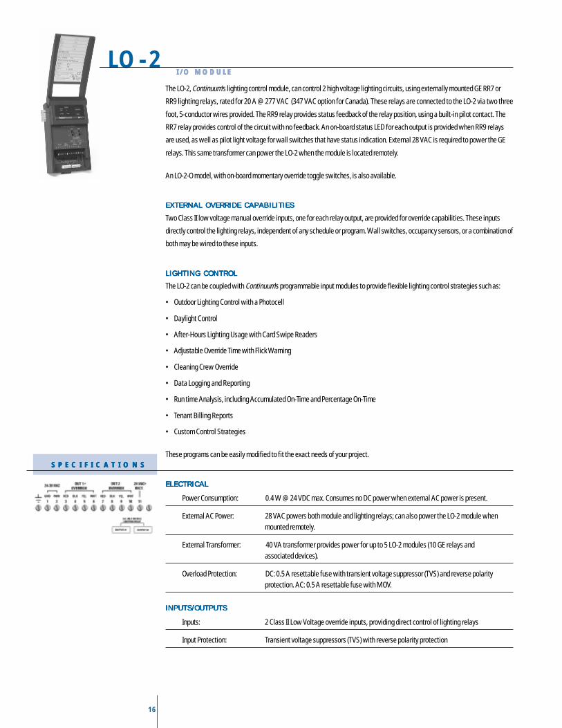
The LO-2, Continuum’s lighting control module, can control 2 high voltage lighting circuits, using externally mounted GE RR7 or
RR9 lighting relays, rated for 20 A @ 277 VAC (347 VAC option for Canada). These relays are connected to the LO-2 via two three
foot, 5-conductor wires provided. The RR9 relay provides status feedback of the relay position, using a built-in pilot contact. The
RR7 relay provides control of the circuit with no feedback. An on-board status LED for each output is provided when RR9 relays
are used, as well as pilot light voltage for wall switches that have status indication. External 28 VAC is required to power the GE
relays. This same transformer can power the LO-2 when the module is located remotely.
An LO-2-O model, with on-board momentary override toggle switches, is also available.
EXTERNAL OVERRIDE CAPABILITIESEXTERNAL OVERRIDE CAPABILITIESEXTERNAL OVERRIDE CAPABILITIESEXTERNAL OVERRIDE CAPABILITIESEXTERNAL OVERRIDE CAPABILITIES
Two Class II low voltage manual override inputs, one for each relay output, are provided for override capabilities. These inputs
directly control the lighting relays, independent of any schedule or program. Wall switches, occupancy sensors, or a combination of
both may be wired to these inputs.
LIGHTING CONTROLLIGHTING CONTROLLIGHTING CONTROLLIGHTING CONTROLLIGHTING CONTROL
The LO-2 can be coupled with Continuum’s programmable input modules to provide flexible lighting control strategies such as:
• Outdoor Lighting Control with a Photocell
• Daylight Control
• After-Hours Lighting Usage with Card Swipe Readers
• Adjustable Override Time with Flick Warning
• Cleaning Crew Override
• Data Logging and Reporting
• Run time Analysis, including Accumulated On-Time and Percentage On-Time
• Tenant Billing Reports
• Custom Control Strategies
These programs can be easily modified to fit the exact needs of your project.
ELECTRICALELECTRICALELECTRICALELECTRICALELECTRICAL
Power Consumption: 0.4 W @ 24 VDC max. Consumes no DC power when external AC power is present.
External AC Power: 28 VAC powers both module and lighting relays; can also power the LO-2 module whenmounted remotely.
External Transformer: 40 VA transformer provides power for up to 5 LO-2 modules (10 GE relays andassociated devices).
Overload Protection: DC: 0.5 A resettable fuse with transient voltage suppressor (TVS) and reverse polarityprotection. AC: 0.5 A resettable fuse with MOV.
INPUTS/OUTPUTSINPUTS/OUTPUTSINPUTS/OUTPUTSINPUTS/OUTPUTSINPUTS/OUTPUTS
Inputs: 2 Class II Low Voltage override inputs, providing direct control of lighting relays
Input Protection: Transient voltage suppressors (TVS) with reverse polarity protection
17
LO-2 I/O MODULE CONTINUEDLO-2 I/O MODULE CONTINUEDLO-2 I/O MODULE CONTINUEDLO-2 I/O MODULE CONTINUEDLO-2 I/O MODULE CONTINUED
M O D E L SM O D E L SM O D E L SM O D E L SM O D E L S
Outputs
Output Type: 2 pulsed lighting control outputs compatible with externally mounted GE RR7 or RR9 relays
Output Rating(Lighting Relay): Lamp Load – 20 A Tungsten Filament @125 VACResistive Load – 20 A ballast @ 277 VAC (@347 VAC, Canada)Motor Load – 0.5 HP @ 110-125 VAC
0.5 HP @ 220-277 VAC(0.5 HP @ 347 VAC, Canada)
Pilot Contact Rating (RR9 only): 1 A @ 24 VAC, isolated
Output Feedback: RR9 relays have LED status indication and software feedback for relay status
Output Protection: Transient voltage suppressors (TVS) on outputs. GE relays provide isolation.
Overrides: Momentary override toggle switches (LO-2-O model only)
AC Power/External Override Input Connections: Two-piece, 12-position removable terminal block
Lighting Relay Connections: 5-position male connector accepts standard GE female plug-in connector.(Two 3-foot, 5-conductor wires with female connectors provided. Wires color-coded tomatch GE relays.)
USER LEDS/SWITCHESUSER LEDS/SWITCHESUSER LEDS/SWITCHESUSER LEDS/SWITCHESUSER LEDS/SWITCHES
Status Indicator LEDSPower Power IndicatorComm TD IndicatorStatus Service/Wink IndicatorOut1-Out2 Two Output Status Indicators (RR-9 only)24 VAC External 24-30 VAC Indicator
SwitchesCommissionReset
LO-2 2 pulsed lighting control outputs
LO-2-O 2 pulsed lighting control outputs with overrides
18
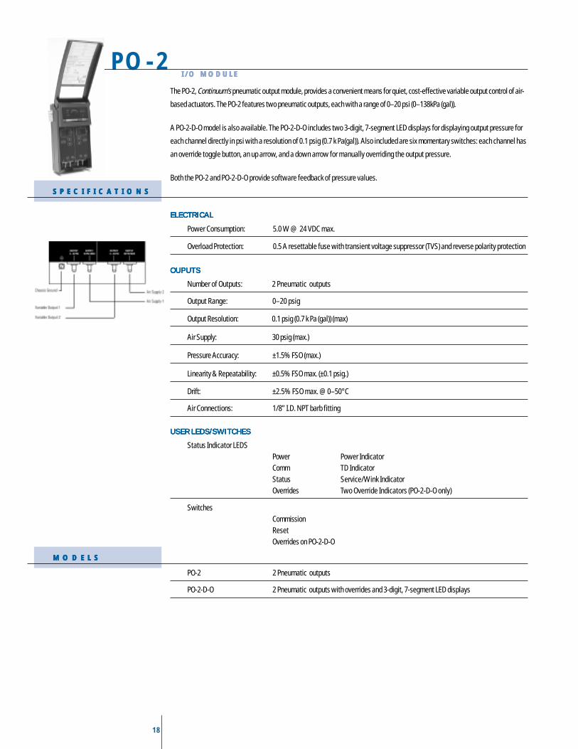
The PO-2, Continuum’s pneumatic output module, provides a convenient means for quiet, cost-effective variable output control of air-
based actuators. The PO-2 features two pneumatic outputs, each with a range of 0–20 psi (0–138kPa (gal)).
A PO-2-D-O model is also available. The PO-2-D-O includes two 3-digit, 7-segment LED displays for displaying output pressure for
each channel directly in psi with a resolution of 0.1 psig (0.7 k Pa(gal)). Also included are six momentary switches: each channel has
an override toggle button, an up arrow, and a down arrow for manually overriding the output pressure.
Both the PO-2 and PO-2-D-O provide software feedback of pressure values.
ELECTRICALELECTRICALELECTRICALELECTRICALELECTRICAL
Power Consumption: 5.0 W @ 24 VDC max.
Overload Protection: 0.5 A resettable fuse with transient voltage suppressor (TVS) and reverse polarity protection
OUPUTSOUPUTSOUPUTSOUPUTSOUPUTS
Number of Outputs: 2 Pneumatic outputs
Output Range: 0–20 psig
Output Resolution: 0.1 psig (0.7 k Pa (gal)) (max)
Air Supply: 30 psig (max.)
Pressure Accuracy: ±1.5% FSO (max.)
Linearity & Repeatability: ±0.5% FSO max. (±0.1 psig.)
Drift: ±2.5% FSO max. @ 0–50°C
Air Connections: 1/8” I.D. NPT barb fitting
USER LEDS/SWITCHESUSER LEDS/SWITCHESUSER LEDS/SWITCHESUSER LEDS/SWITCHESUSER LEDS/SWITCHES
Status Indicator LEDSPower Power IndicatorComm TD IndicatorStatus Service/Wink IndicatorOverrides Two Override Indicators (PO-2-D-O only)
SwitchesCommissionResetOverrides on PO-2-D-O
PO-2I / O M O D U L EI / O M O D U L EI / O M O D U L EI / O M O D U L EI / O M O D U L E
S P E C I F I C A T I O N SS P E C I F I C A T I O N SS P E C I F I C A T I O N SS P E C I F I C A T I O N SS P E C I F I C A T I O N S
M O D E L SM O D E L SM O D E L SM O D E L SM O D E L S
PO-2 2 Pneumatic outputs
PO-2-D-O 2 Pneumatic outputs with overrides and 3-digit, 7-segment LED displays
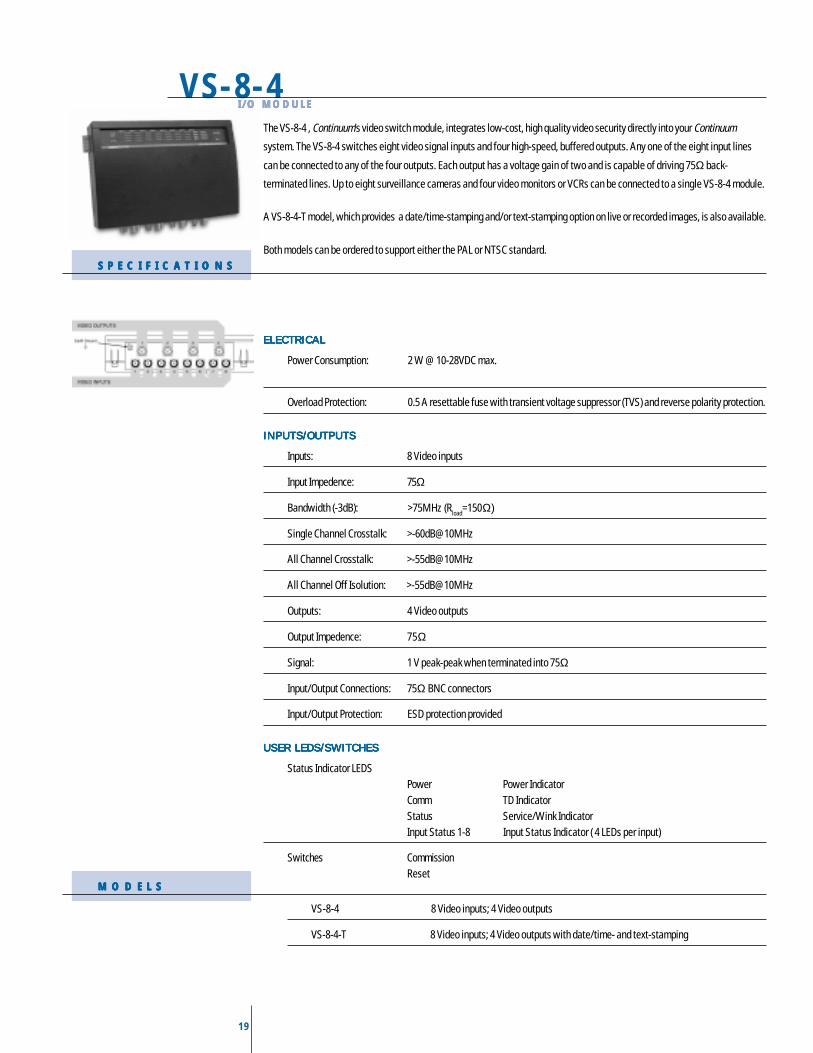
19
The VS-8-4 , Continuum’s video switch module, integrates low-cost, high quality video security directly into your Continuum
system. The VS-8-4 switches eight video signal inputs and four high-speed, buffered outputs. Any one of the eight input lines
can be connected to any of the four outputs. Each output has a voltage gain of two and is capable of driving 75Ω back-
terminated lines. Up to eight surveillance cameras and four video monitors or VCRs can be connected to a single VS-8-4 module.
A VS-8-4-T model, which provides a date/time-stamping and/or text-stamping option on live or recorded images, is also available.
Both models can be ordered to support either the PAL or NTSC standard.
ELECTRICALELECTRICALELECTRICALELECTRICALELECTRICAL
Power Consumption: 2 W @ 10-28VDC max.
Overload Protection: 0.5 A resettable fuse with transient voltage suppressor (TVS) and reverse polarity protection.
INPUTS/OUTPUTSINPUTS/OUTPUTSINPUTS/OUTPUTSINPUTS/OUTPUTSINPUTS/OUTPUTS
Inputs: 8 Video inputs
Input Impedence: 75Ω
Bandwidth (-3dB): >75MHz (Rload=150Ω)
Single Channel Crosstalk: >-60dB@10MHz
All Channel Crosstalk: >-55dB@10MHz
All Channel Off Isolution: >-55dB@10MHz
Outputs: 4 Video outputs
Output Impedence: 75Ω
Signal: 1 V peak-peak when terminated into 75Ω
Input/Output Connections: 75Ω BNC connectors
Input/Output Protection: ESD protection provided
USER LEDS/SWITCHESUSER LEDS/SWITCHESUSER LEDS/SWITCHESUSER LEDS/SWITCHESUSER LEDS/SWITCHES
Status Indicator LEDSPower Power IndicatorComm TD IndicatorStatus Service/Wink IndicatorInput Status 1-8 Input Status Indicator ( 4 LEDs per input)
Switches CommissionReset
VS-8-4I/O MODULEI/O MODULEI/O MODULEI/O MODULEI/O MODULE
S P E C I F I C A T I O N SS P E C I F I C A T I O N SS P E C I F I C A T I O N SS P E C I F I C A T I O N SS P E C I F I C A T I O N S
M O D E L SM O D E L SM O D E L SM O D E L SM O D E L S
VS-8-4 8 Video inputs; 4 Video outputs
VS-8-4-T 8 Video inputs; 4 Video outputs with date/time- and text-stamping
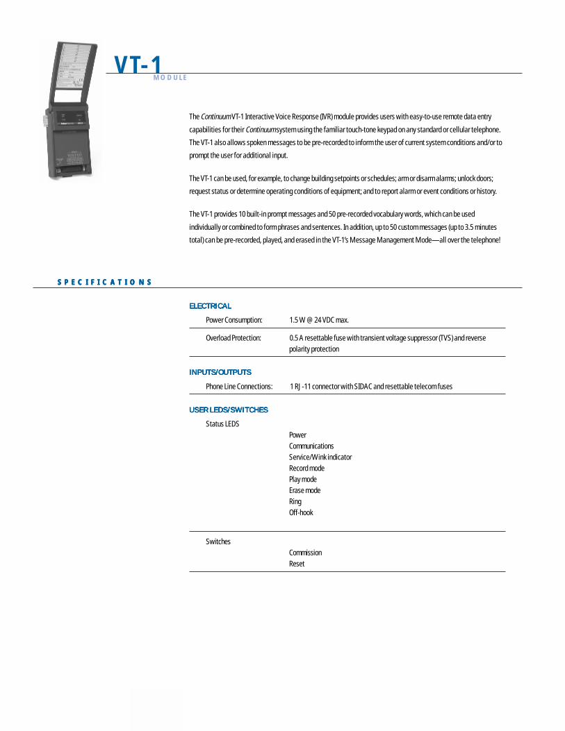
20
The Continuum VT-1 Interactive Voice Response (IVR) module provides users with easy-to-use remote data entry
capabilities for their Continuum system using the familiar touch-tone keypad on any standard or cellular telephone.
The VT-1 also allows spoken messages to be pre-recorded to inform the user of current system conditions and/or to
prompt the user for additional input.
The VT-1 can be used, for example, to change building setpoints or schedules; arm or disarm alarms; unlock doors;
request status or determine operating conditions of equipment; and to report alarm or event conditions or history.
The VT-1 provides 10 built-in prompt messages and 50 pre-recorded vocabulary words, which can be used
individually or combined to form phrases and sentences. In addition, up to 50 custom messages (up to 3.5 minutes
total) can be pre-recorded, played, and erased in the VT-1’s Message Management Mode—all over the telephone!
ELECTRICALELECTRICALELECTRICALELECTRICALELECTRICAL
Power Consumption: 1.5 W @ 24 VDC max.
Overload Protection: 0.5 A resettable fuse with transient voltage suppressor (TVS) and reversepolarity protection
INPUTS/OUTPUTSINPUTS/OUTPUTSINPUTS/OUTPUTSINPUTS/OUTPUTSINPUTS/OUTPUTS
Phone Line Connections: 1 RJ-11 connector with SIDAC and resettable telecom fuses
USER LEDS/SWITCHESUSER LEDS/SWITCHESUSER LEDS/SWITCHESUSER LEDS/SWITCHESUSER LEDS/SWITCHES
Status LEDSPowerCommunicationsService/Wink indicatorRecord modePlay modeErase modeRingOff-hook
SwitchesCommissionReset
VT-1 MODULE
S P E C I F I C A T I O N SS P E C I F I C A T I O N SS P E C I F I C A T I O N SS P E C I F I C A T I O N SS P E C I F I C A T I O N S

21
22
Copyright 2000, Andover Controls Corporation. Data subject to change without notice.All brand names, trademarks and registered trademarks are the property of their respective holders.Consult Andover Product Installation Guides for exact installation instructions and specifications.
#DS-C-I/O MODULE-D
Andover Controls Corporation World Headquarters
300 Brickstone Square
Andover, Massachusetts 01810 USA
Tel: 978 470 0555 • Fax: 978 470 0946
http://www.andovercontrols.com
Andover Controls Ltd.
Smisby Road • Ashby-de-la-Zouch
Leicestershire LE65 2UG, England
Tel: 01530 417733 • Fax: 01530 415436
Andover Control GmbH
Am Seerhein 8
D-78467 Konstanz, Germany
Tel: 07531 99370 • Fax: 07531 993710
Andover Control S.A.
Immeuble Dolomites 2
58 Rue Roger Salengro
94126 Fontenay Sous
Bois Cedex, France
Tel: 331 53 99 16 16 • Fax: 331 53 99 16 15
Andover Controls Asia
Unit 1201-02, Phase I, Cheuk Nang Centre
9 Hillwood Road, Tsim Sha Tsui
Kowloon, Hong Kong
Tel: 852 2739 5497 • Fax: 852 2739 7350
Andover Controls Mexico
Insurgentes Sur 1722-501
Col. Florida
Mexico D.F. 01030, Mexico
Tel: 525 661 56 72 • Fax: 525 661 54 15

www.tac.com
Copyright © 2006, TAC All brand names, trademarks and registered trademarks are the property of their respective owners. Information contained within this document is subject to change without notice. All rights reserved.
09/06