Embed Size (px)
Citation preview

TIA Portal Module 032-500Analog Valuesfor SIMATIC S7-1500
For unrestricted use in educational and R&D institutions. © Siemens AG 2017. All rights reserved.
SCE Training CurriculumSiemens Automation Cooperates with Education | 05/2017

SCE Training Curriculum | TIA Portal Module 032-500, Edition 05/2017 | Digital Factory, DF FA
Matching SCE trainer packages for these training curriculums
SIMATIC Controllers• SIMATIC ET 200SP Open Controller CPU 1515SP PC F and HMI RT SW
Order no.: 6ES7677-2FA41-4AB1• SIMATIC ET 200SP Distributed Controller CPU 1512SP F-1 PN Safety
Order no.: 6ES7512-1SK00-4AB2• SIMATIC CPU 1516F PN/DP Safety
Order no.: 6ES7516-3FN00-4AB2• SIMATIC S7 CPU 1516-3 PN/DP
Order no.: 6ES7516-3AN00-4AB3• SIMATIC CPU 1512C PN with Software and PM 1507
Order no.: 6ES7512-1CK00-4AB1• SIMATIC CPU 1512C PN with Software, PM 1507 and CP 1542-5 (PROFIBUS)
Order no.: 6ES7512-1CK00-4AB2• SIMATIC CPU 1512C PN with Software
Order no.: 6ES7512-1CK00-4AB6• SIMATIC CPU 1512C PN with Software and CP 1542-5 (PROFIBUS)
Order no.: 6ES7512-1CK00-4AB7
SIMATIC STEP 7 Software for Training• SIMATIC STEP 7 Professional V14 SP1 - Single license
Order no.: 6ES7822-1AA04-4YA5• SIMATIC STEP 7 Professional V14 SP1- Classroom license (up to 6 users)
Order no.: 6ES7822-1BA04-4YA5• SIMATIC STEP 7 Professional V14 SP1 - Upgrade license (up to 6 users)
Order no.: 6ES7822-1AA04-4YE5• SIMATIC STEP 7 Professional V14 SP1 - Student license (up to 20 users)
Order no.: 6ES7822-1AC04-4YA5
Please note that these trainer packages are replaced with successor packages when necessary.An overview of the currently available SCE packages is provided at: siemens.com/sce/tp
Continued trainingFor regional Siemens SCE continued training, please contact your regional SCE contact siemens.com/sce/contact
Additional information regarding SCE siemens.com/sce
Information regarding useFor unrestricted use in educational and R&D institutions. © Siemens AG 2017. All rights reserved. 2
document.docx

SCE Training Curriculum | TIA Portal Module 032-500, Edition 05/2017 | Digital Factory, DF FA
The SCE training curriculum for the integrated automation solution Totally Integrated Automation (TIA) was prepared for the program "Siemens Automation Cooperates with Education (SCE)" specifically for training purposes for public educational and R&D institutions. Siemens AG does not guarantee the contents.
This document is to be used only for initial training on Siemens products/systems. This means it can be copied in whole or part and given to those being trained for use within the scope of their training. Circulation or copying this training curriculum and sharing its content is permitted within public training and advanced training facilities for training purposes.
Exceptions require written consent from the Siemens AG contact: Roland Scheuerer [email protected].
Offenders will be held liable. All rights including translation are reserved, particularly if a patent is granted or a utility model or design is registered.
Use for industrial customer courses is expressly prohibited. We do not consent to commercial use of the training curriculums.
We wish to thank the TU Dresden, especially Prof. Dr.-Ing. Leon Urbas, the Michael Dziallas Engineering Corporation and all other involved persons for their support during the preparation of this training curriculum.
For unrestricted use in educational and R&D institutions. © Siemens AG 2017. All rights reserved. 3
document.docx

SCE Training Curriculum | TIA Portal Module 032-500, Edition 05/2017 | Digital Factory, DF FA
Table of contents1 Goal..................................................................................................................................................... 5
2 Prerequisite.......................................................................................................................................... 5
3 Required hardware and software.........................................................................................................6
4 Theory.................................................................................................................................................. 7
4.1 Analog signals............................................................................................................................. 7
4.2 Measuring transducers................................................................................................................8
4.3 Analog modules – A/D converter.................................................................................................8
4.4 Data types of the SIMATIC S7-1500............................................................................................9
4.5 Reading/outputting analog values..............................................................................................10
4.6 Normalizing analog values.........................................................................................................11
5 Task................................................................................................................................................... 12
6 Planning............................................................................................................................................. 12
6.1 Analog control of the conveyor speed........................................................................................12
6.2 Technology diagram.................................................................................................................. 13
6.3 Reference list............................................................................................................................. 14
7 Structured step-by-step instructions...................................................................................................15
7.1 Retrieve an existing project........................................................................................................15
7.2 Create the "MOTOR_SPEEDCONTROL" function....................................................................17
7.3 Configuration of the analog output channel...............................................................................24
7.4 Expand the tag table to include analog signals..........................................................................25
7.5 Call the block in the organization block......................................................................................26
7.6 Save and compile the program..................................................................................................29
7.7 Download the program...............................................................................................................30
7.8 Monitor program blocks.............................................................................................................31
7.9 Archive the project..................................................................................................................... 33
8 Checklist............................................................................................................................................ 34
9 Exercise............................................................................................................................................. 35
9.1 Task – Exercise......................................................................................................................... 35
9.2 Technology diagram.................................................................................................................. 36
9.3 Reference list............................................................................................................................. 37
9.4 Planning..................................................................................................................................... 37
9.5 Checklist – Exercise................................................................................................................... 38
10 Additional information........................................................................................................................39
For unrestricted use in educational and R&D institutions. © Siemens AG 2017. All rights reserved. 4
document.docx

SCE Training Curriculum | TIA Portal Module 032-500, Edition 05/2017 | Digital Factory, DF FA
ANALOG VALUES FOR SIMATIC S7-1500
1 GoalIn this chapter, you will become acquainted with the analog value processing of the SIMATIC S7-1500 with the TIA Portal programming tool.
The module explains the acquisition and processing of analog signals and gives a step-by-step description of read and write access to analog values in the SIMATIC S7-1500.
The SIMATIC S7 controllers listed in Chapter 3 can be used.
2 PrerequisiteThis chapter builds on the chapter IEC Timers and Counters with the SIMATIC S7 CPU1516F-3 PN/DP. You can use the following project for this chapter, for example: 032-300 IEC Timers and Counters.zap13
For unrestricted use in educational and R&D institutions. © Siemens AG 2017. All rights reserved. 5
document.docx
SCE Training Curriculum | TIA Portal Module 032-500, Edition 05/2017 | Digital Factory, DF FA
3 Required hardware and software1 Engineering station: requirements include hardware and operating system
(for additional information, see Readme on the TIA Portal Installation DVDs)
2 SIMATIC STEP 7 Professional software in TIA Portal – as of V13
3 SIMATIC S7-1500/S7-1200/S7-300 controller, e.g. CPU 1516F-3 PN/DP –
Firmware as of V1.6 with memory card and 16DI/16DO and 2AI/1AO
Note: The digital inputs and analog inputs and outputs should be fed out to a control panel.
4 Ethernet connection between engineering station and controller
For unrestricted use in educational and R&D institutions. © Siemens AG 2017. All rights reserved. 6
document.docx
2 SIMATIC STEP 7 Professional (TIA Portal) as of V13
3 SIMATIC S7-1500 controller
1 Engineering station
4 Ethernet connection
Control panel

SCE Training Curriculum | TIA Portal Module 032-500, Edition 05/2017 | Digital Factory, DF FA
4 Theory
4.1 Analog signals
In contrast to a binary signal, which can assume only two signal states (“Voltage present +24 V” and “Voltage not present 0 V”), analog signals can assume any value within a defined range. A typical example of an analog sensor is a potentiometer. Depending on the position of the knob, any resistance can be set, up to the maximum value.
Examples of analog quantities in control engineering:
- Temperature -50 to +150 °C
- Flow rate 0 to 200 l/min
- Speed -500 to +50 rpm
- etc.
For unrestricted use in educational and R&D institutions. © Siemens AG 2017. All rights reserved. 7
document.docx

SCE Training Curriculum | TIA Portal Module 032-500, Edition 05/2017 | Digital Factory, DF FA
4.2 Measuring transducers
These quantities are converted to electrical voltages, currents or resistances with the help of a measuring transducer. If, for example, a speed is to be measured, the speed range of 500 to 1500 rpm can be converted to a voltage range of 0 to +10 V using a measuring transducer. At a measured speed of 865 rpm, the measuring transducer would output a voltage value of +3.65 V.
365
1000 U/min
10V
10V: 1000 U/min = 0,01 V/U/min
365 U/min x 0,01 V/U/min = 3,65
0 V +10V
500 865 1500 U/min
4.3 Analog modules – A/D converter
These electrical voltages, currents or resistances are then connected to an analog module that digitizes this signal for further processing in the PLC.
If analog quantities will be processed with a PLC, the read-in voltage, current or resistance value must be converted to digital information. The analog value is converted to a bit pattern. This conversion is referred to as analog-to-digital conversion (A/D conversion). This means, for example, that the voltage value of 3.65 V is stored as information in a series of binary digits.
The result of this conversion is always a 16-bit word for SIMATIC products. The integrated ADC (analog-to-digital converter) of the analog input module digitizes the analog signal being acquired and approximates its value in the form of a stepped curve. The most important parameters of an ADC are its resolution and conversion rate.
1: Analog value
2. Digital value
For unrestricted use in educational and R&D institutions. © Siemens AG 2017. All rights reserved. 8
document.docx
10 V: 1000 rpm = 0.01 V/rpm365 rpm x 0.01 V/rpm = 3.65 V
1500 rpm
+10 V
1000 rpm

SCE Training Curriculum | TIA Portal Module 032-500, Edition 05/2017 | Digital Factory, DF FA
The more binary digits the digital representation uses, the finer the resolution is. For example, if only 1 bit was available for the voltage range of 0 to +10 V, you would only know whether the measured voltage is between 0 and +5 V or between +5 V and +10 V. With 2 bits, the range can be divided into 4 individual ranges, i.e., 0 to 2.5 / 2.5 to 5 / 5 to 7.5 / 7.5 to 10 V. Conventional A/D converters in control engineering use 8 or 11 bits for converting.
With 8 bits you have 256 individual ranges, while 11 bits provide a resolution of 2048 individual ranges.
4.4 Data types of the SIMATIC S7-1500The SIMATIC S7-1500 has many different data types for representing different numerical formats. A list of some of the elementary data types is given below.
Data type Size (bits) Range Example of constant entryBool 1 0 to 1 TRUE, FALSE, O, 1Byte 8 16#00 to 16#FF 16#12, 16#ABWord 16 16#0000 to 16#FFFF 16#ABCD, 16#0001DWord 32 16#00000000 to 16#FFFFFFFF 16#02468ACEChar 8 16#00 to 16#FF 'A', ‘r’, ‘@’Sint 8 -128 to 127 123,-123Int 16 -32,768 to 32,767 123, -123Dint 32 -2,147,483,648 to 2,147,483,647 123, -123USInt 8 0 to 255 123Ulnt 16 0 to 65,535 123UDInt 32 0 to 4,294,967,295 123Real 32 +/-1.18 x 10 -38 to +/-3.40 x 10 38 123.456, -3.4, -1.2E+12, 3.4E-
3LReal 64 +/-2.23 x 10 -308 to +/-1.79 x 10 308 12345.123456789
-1.2E+40Time 32 T#-24d_20h_31 m_23s_648ms to
T#24d_20h_31 m_23s_647msSaved as: -2,147,483,648 ms to +2,147,483,647 ms
T#5m_30s5#-2dT#1d_2h_15m_30x_45ms
String Variable 0 to 254 characters in byte size 'ABC'
Note: The 'INT' and 'REAL' data types play a large role in analog value processing. This is because read-in analog values exist as 16-bit integers in the ' INT' format, and in order to ensure exact further processing only 'REAL' floating-point numbers should be used due to rounding errors in the case of 'INT'.
For unrestricted use in educational and R&D institutions. © Siemens AG 2017. All rights reserved. 9
document.docx
10 V: 2048 = 0.0048828 Voltage differences of <5 mV can be detected
20mA/10V0A/0V
2048
11-bit

SCE Training Curriculum | TIA Portal Module 032-500, Edition 05/2017 | Digital Factory, DF FA
4.5 Reading/outputting analog valuesAnalog values are read into the PLC or output from the PLC as word information. These words are accessed, for example, with the following operands:
%IW 64 Analog input word 64%QW 64 Analog output word 64
Each analog value (“channel”) occupies one input or output word. The format is ‘Int’, an integer.
The addressing of input and output words conforms to the addressing in the device overview. For example:
Here, the address of the first analog input would be %IW 64, that of the second analog input %IW 66, that of the third analog input %IW68, that of the fourth analog input %IW70, that of the fifth analog input %IW72, that of the sixth analog input %IW74, that of the seventh analog input %IW 76 and that of the eighth analog input %IW78.
The address of the first analog output would be %QW64, that of the second analog output %QW66, that of the third analog output %QW 68 and that of the fourth analog output %QW70.
For unrestricted use in educational and R&D institutions. © Siemens AG 2017. All rights reserved. 10
document.docx

SCE Training Curriculum | TIA Portal Module 032-500, Edition 05/2017 | Digital Factory, DF FA
The analog value transformation for further processing in the PLC is the same for analog inputs and analog outputs.The digitized value ranges are as follows:
Often, these digitized values still have to be normalized by further processing them in the PLC in an appropriate manner.
4.6 Normalizing analog values
If an analog input value exists as a digitized value in the range +/- 27648, it must usually still be normalized so that the numerical values correspond to the physical quantities in the process.
Likewise, the analog output usually results from setting of a normalized value that then still has to be scaled to the output value +/- 27648.
In the TIA Portal, ready-made blocks or arithmetic operations are used for normalizing and scaling.For this to be carried out as exactly as possible, the values for the normalizing must be converted to the REAL data type to minimize rounding errors.
For unrestricted use in educational and R&D institutions. © Siemens AG 2017. All rights reserved. 11
document.docx
Nominal range of the analog value20mA/10V0A/0V
27648Digitalized value for further processing in the PLC13824
10 mA/5 V

SCE Training Curriculum | TIA Portal Module 032-500, Edition 05/2017 | Digital Factory, DF FA
5 TaskIn this chapter, a function for analog control of the conveyor speed will be added to the program from chapter "SCE_EN_032-300 IEC Timers and Counters".
6 PlanningThe analog control of the conveyor speed will be programmed in the "MOTOR_SPEEDCONTROL" [FC10] function as an expansion of the "SCE_EN_032-300 IEC Timers and Counters" project. This project must be retrieved from the archive in order to add this function. The "MOTOR_ SPEEDCONTROL" [FC10] function will be called in the "Main“ [OB1]" organization block and wired. The control of the conveyor motor must be changed to - Q3 (conveyor motor -M1 variable speed).
6.1 Analog control of the conveyor speed
The speed will be set at an input of the "MOTOR_SPEEDCONTROL" [FC10] function in revolutions per minute (range: +/- 50 rpm). The data type is 32-bit floating-point number (Real).
First, the function will be checked for correct entry of the speed setpoint in the range +/- 50 rpm.
If the speed setpoint is outside the range +/- 50 rpm, the value 0 with data type 16-bit integer (Int) will be output at the output. The return value of the function (Ret_Val) will then be assigned the value TRUE (1).
If the speed setting is within the range +/- 50 rpm, this value will first be normalized to the range 0…1 and then scaled to +/- 27648 with data type 16-bit integer (Int) for output as the speed manipulated value at the analog output.
The output will then be connected with signal U1 (manipulated value speed of the motor in 2 directions +/- 10V corresponds to +/- 50 rpm).
For unrestricted use in educational and R&D institutions. © Siemens AG 2017. All rights reserved. 12
document.docx

SCE Training Curriculum | TIA Portal Module 032-500, Edition 05/2017 | Digital Factory, DF FA
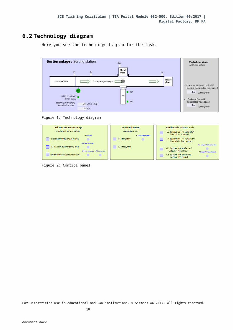
6.2 Technology diagramHere you see the technology diagram for the task.
Figure 1: Technology diagram
Figure 2: Control panel
For unrestricted use in educational and R&D institutions. © Siemens AG 2017. All rights reserved. 13
document.docx

SCE Training Curriculum | TIA Portal Module 032-500, Edition 05/2017 | Digital Factory, DF FA
6.3 Reference listThe following signals are required as global operands for this task.
DI Type Identifier Function NC/NO
I 0.0 BOOL -A1 Return signal emergency stop OK NC
I 0.1 BOOL -K0 Main switch "ON" NO
I 0.2 BOOL -S0 Mode selector manual (0)/ automatic (1)Manual = 0
Auto = 1
I 0.3 BOOL -S1 Pushbutton automatic start NO
I 0.4 BOOL -S2 Pushbutton automatic stop NC
I 0.5 BOOL -B1 Sensor cylinder -M4 retracted NO
I 1.0 BOOL -B4 Sensor part at slide NO
I 1.3 BOOL -B7 Sensor part at end of conveyor NO
DO Type Identifier Function
Q 0.2 BOOL -Q3 Conveyor motor -M1 variable speed
QW 64 BOOL -U1 Manipulated value speed of the motor in 2 directions +/- 10V corresponds to +/- 50 rpm
Legend for reference list
For unrestricted use in educational and R&D institutions. © Siemens AG 2017. All rights reserved. 14
document.docx
DO Digital Output
AO Analog Output
Q Output
DI Digital Input
AI Analog Input
I Input
NC Normally Closed
NO Normally Open

SCE Training Curriculum | TIA Portal Module 032-500, Edition 05/2017 | Digital Factory, DF FA
7 Structured step-by-step instructionsYou can find instructions on how to carry out planning below. If you already have a good understanding of everything, it will be sufficient to focus on the numbered steps. Otherwise, simply follow the detailed steps in the instructions.
7.1 Retrieve an existing project
Before we can expand the "SCE_EN_032-300_IEC_Timers_Counters.zap13 project from
chapter "SCE_EN_032-300_IEC_Timers_Counters", we must retrieve this project from
the archive. To retrieve an existing project that has been archived, you must select the
relevant archive with Project Retrieve in the project view. Confirm your selection with
Open.
( Project Retrieve Select a .zap archive Open)
The next step is to select the target directory where the retrieved project will be stored.
Confirm your selection with "OK".
( Target directory OK)
For unrestricted use in educational and R&D institutions. © Siemens AG 2017. All rights reserved. 15
document.docx

SCE Training Curriculum | TIA Portal Module 032-500, Edition 05/2017 | Digital Factory, DF FA
Save the opened project under the name 032-500_Analog_Values.
( Project Save as … 032-500_Analog_Values Save)
For unrestricted use in educational and R&D institutions. © Siemens AG 2017. All rights reserved. 16
document.docx

SCE Training Curriculum | TIA Portal Module 032-500, Edition 05/2017 | Digital Factory, DF FA
7.2 Create the "MOTOR_SPEEDCONTROL" function
Select the 'Program blocks' folder of your CPU 1516F-3 PN/DP and then click "Add new
block" to create a new function there.
( CPU_1516F [CPU 1516F-3 PN/DP] Add new block)
Select in the next dialog and rename your new block to:
"MOTOR_SPEEDCONTROL". Set the language to FBD and manually assign the number
"10". Select the "Add new and open" check box. Click "OK".
( Name: MOTOR_SPEEDCONTROL Language: FBD Number: 10 Manual
Add new and open OK)
For unrestricted use in educational and R&D institutions. © Siemens AG 2017. All rights reserved. 17
document.docx
SCE Training Curriculum | TIA Portal Module 032-500, Edition 05/2017 | Digital Factory, DF FA
Create the local tags with their comments as shown here and change the data type of the
'Return' tag from 'Void' to 'Bool'.
( Bool)
Note: Be sure to use the correct data types.
Insert an Assignment ' ' in the first network and an 'And' ' in front of it. Then use
drag-and-drop to move the 'Comparator operation' 'Less or equal' from the 'Basic
instructions' onto the first input of the AND logic operation.
( Basic instructions Comparator operations CMP<=)
For unrestricted use in educational and R&D institutions. © Siemens AG 2017. All rights reserved. 18
document.docx

SCE Training Curriculum | TIA Portal Module 032-500, Edition 05/2017 | Digital Factory, DF FA
Next use drag-and-drop to move the 'Comparator operation' 'Greater or equal' onto the
second input of the AND logic operation.
( Basic instructions Comparator operations CMP>=)
Connect the contacts in Network 1 with the constants and local tags as shown here. The
data types in the comparator operations are automatically adapted to 'Real'.
For unrestricted use in educational and R&D institutions. © Siemens AG 2017. All rights reserved. 19
document.docx

SCE Training Curriculum | TIA Portal Module 032-500, Edition 05/2017 | Digital Factory, DF FA
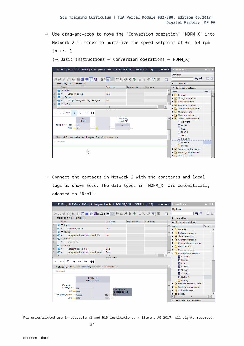
Use drag-and-drop to move the 'Conversion operation' 'NORM_X' into Network 2 in order
to normalize the speed setpoint of +/- 50 rpm to +/- 1.
( Basic instructions Conversion operations NORM_X)
Connect the contacts in Network 2 with the constants and local tags as shown here. The
data types in 'NORM_X' are automatically adapted to 'Real'.
For unrestricted use in educational and R&D institutions. © Siemens AG 2017. All rights reserved. 20
document.docx

SCE Training Curriculum | TIA Portal Module 032-500, Edition 05/2017 | Digital Factory, DF FA
Use drag-and-drop to move the 'Conversion operation' 'SCALE_X' into Network 3 in order
to scale the speed setpoint from the normalized +/- 1 onto the range for the analog output
+/- 27468.
( Basic instructions Conversion operations SCALE_X)
Connect the contacts with the constants and local tags in Network 3 as well, as shown
here. The data types in 'SCALE_X' are automatically changed to 'Real' or 'Int'.
For unrestricted use in educational and R&D institutions. © Siemens AG 2017. All rights reserved. 21
document.docx

SCE Training Curriculum | TIA Portal Module 032-500, Edition 05/2017 | Digital Factory, DF FA
Insert an Assignment ' ' in the fourth network. Use drag-and-drop to move the 'Move'
command from the 'Move operations' folder under 'Basic instructions' in front of the
Assignment.
( Basic instructions Move operations MOVE)
The contacts in Network 4 will now be connected with constants and local tags as shown
here. If the speed setpoint is not within the range +/- 50 rpm, the value '0' is output at the
analog output and the value TRUE is assigned to the return value (Return) of the
"MOTOR_SPEEDCONTROL“ function.
For unrestricted use in educational and R&D institutions. © Siemens AG 2017. All rights reserved. 22
document.docx

SCE Training Curriculum | TIA Portal Module 032-500, Edition 05/2017 | Digital Factory, DF FA
Do not forget to click . The finished function "MOTOR_SPEEDCONTROL"
[FC10] in FBD is shown below.
For unrestricted use in educational and R&D institutions. © Siemens AG 2017. All rights reserved. 23
document.docx

SCE Training Curriculum | TIA Portal Module 032-500, Edition 05/2017 | Digital Factory, DF FA
7.3 Configuration of the analog output channel
Double-click the 'Device configuration' to open it.
Check the address setting and the configuration of the analog output channel 0.
( Q address: 64…71 Properties General Output 0 - 3 Outputs Channel 0
Output type: Voltage Output range: +/- 10 V Reaction to CPU STOP: Shutdown)
For unrestricted use in educational and R&D institutions. © Siemens AG 2017. All rights reserved. 24
document.docx

SCE Training Curriculum | TIA Portal Module 032-500, Edition 05/2017 | Digital Factory, DF FA
7.4 Expand the tag table to include analog signals
Double-click the 'Tag table_sorting station' to open it.
Add the global tags for the analog value processing to the "Tag table_sorting station". An
analog input B8 and an analog output U1 must be added.
( U1 %QW64 B8 %IW64)
For unrestricted use in educational and R&D institutions. © Siemens AG 2017. All rights reserved. 25
document.docx

SCE Training Curriculum | TIA Portal Module 032-500, Edition 05/2017 | Digital Factory, DF FA
7.5 Call the block in the organization block
Open the "Main [OB1]" organization block with a double-click.
Add the temporary tag 'Motor_speed_monitoring_Ret_Val' to the local tags of OB1. These
will be needed in order to interconnect the return value of the
"MOTOR_SPEEDCONTROL" function.
( Temp Motor_speed_monitoring_Ret_Val Bool)
For unrestricted use in educational and R&D institutions. © Siemens AG 2017. All rights reserved. 26
document.docx
SCE Training Curriculum | TIA Portal Module 032-500, Edition 05/2017 | Digital Factory, DF FA
Select the block title of OB1 and then click ' ' to insert a new Network 1 in front of the
other networks
( )
Use drag-and-drop to move your "MOTOR_SPEEDCONTROL [FC10]" function onto the
green line in Network 1.
For unrestricted use in educational and R&D institutions. © Siemens AG 2017. All rights reserved. 27
document.docx

SCE Training Curriculum | TIA Portal Module 032-500, Edition 05/2017 | Digital Factory, DF FA
Connect the contacts with the constants and global and local tags here as shown.
Change the connection of output tag "Conveyor_motor_automatic_mode" in Network 2 to
'-Q3' (Conveyor motor -M1 variable speed) so that the conveyor motor is controlled taking
the analog speed setting into consideration.
( -Q3)
For unrestricted use in educational and R&D institutions. © Siemens AG 2017. All rights reserved. 28
document.docx

SCE Training Curriculum | TIA Portal Module 032-500, Edition 05/2017 | Digital Factory, DF FA
7.6 Save and compile the program
To save your project, select the button in the menu. To compile all blocks,
click the "Program blocks" folder and select the icon for compiling in the menu.
( Program blocks )
The "Info", "Compile" area shows which blocks were successfully compiled.
For unrestricted use in educational and R&D institutions. © Siemens AG 2017. All rights reserved. 29
document.docx
SCE Training Curriculum | TIA Portal Module 032-500, Edition 05/2017 | Digital Factory, DF FA
7.7 Download the program
After successful compilation, the complete controller with the created program including
the hardware configuration can, as described in the previous modules, be downloaded.
( )
For unrestricted use in educational and R&D institutions. © Siemens AG 2017. All rights reserved. 30
document.docx

SCE Training Curriculum | TIA Portal Module 032-500, Edition 05/2017 | Digital Factory, DF FA
7.8 Monitor program blocks
The desired block must be open for monitoring the downloaded program. The monitoring
can now be activated/deactivated by clicking the icon.
( Main [OB1] )
For unrestricted use in educational and R&D institutions. © Siemens AG 2017. All rights reserved. 31
document.docx

SCE Training Curriculum | TIA Portal Module 032-500, Edition 05/2017 | Digital Factory, DF FA
The "MOTOR_SPEEDCONTROL" [FC10] function called in the "Main [OB1]" organization
block can be selected directly for "Open and monitor" after right-clicking and the program
code in the function can thus be monitored.
( "MOTOR_SPEEDCONTROL" [FC10] Open and monitor)
For unrestricted use in educational and R&D institutions. © Siemens AG 2017. All rights reserved. 32
document.docx

SCE Training Curriculum | TIA Portal Module 032-500, Edition 05/2017 | Digital Factory, DF FA
7.9 Archive the project
As the final step, we want to archive the complete project. Select the 'Archive ...'
command in the 'Project' menu. Select a folder where you want to archive your project
and save it with the file type "TIA Portal project archive".
( Project Archive TIA Portal project archive 032-500_Analog_Values…. Save)
For unrestricted use in educational and R&D institutions. © Siemens AG 2017. All rights reserved. 33
document.docx

SCE Training Curriculum | TIA Portal Module 032-500, Edition 05/2017 | Digital Factory, DF FA
8 Checklist
No. Description Completed
1 Compiling successful and without error message
2 Download successful and without error message
3
Switch on station (-K0 = 1)Cylinder retracted / Feedback activated (-B1 = 1)EMERGENCY OFF (-A1 = 1) not activatedAUTOMATIC mode (-S0 = 1)Pushbutton automatic stop not actuated (-S2 = 1)Briefly press the automatic start pushbutton (-S1 = 1)Sensor part at slide activated (-B4 = 1)then Conveyor motor M1 variable speed (-Q3 = 1)switches on and stays on.The speed corresponds to the speed setpoint in the range +/- 50 rpm
4 Sensor part at end of conveyor activated (-B7 = 1) -Q3 = 0 (after 2 seconds)
5 Briefly press the automatic stop pushbutton (-S2 = 0) -Q3 = 0
6 Activate EMERGENCY OFF (-A1 = 0) -Q3 = 0
7 Manual mode (-S0 = 0) -Q3 = 0
8 Switch off station (-K0 = 0) -Q3 = 0
9 Cylinder not retracted (-B1 = 0) -Q3 = 0
10 Project successfully archived
For unrestricted use in educational and R&D institutions. © Siemens AG 2017. All rights reserved. 34
document.docx

SCE Training Curriculum | TIA Portal Module 032-500, Edition 05/2017 | Digital Factory, DF FA
9 Exercise
9.1 Task – Exercise
In this exercise a "MOTOR_SPEEDMONITORING" [FC11] function will be created additionally.
The actual value will be made available to -B8 (sensor actual value speed of the motor +/-10V corresponds to +/- 50 rpm) as an analog value and queried at an input of the "MOTOR_SPEEDMONITORING" [FC11] function. The data type is 16-bit integer (Int.).
This actual speed value will first be normalized to the range +/- 1 as 32-bit floating-point number (Real) in the function.
The normalized actual speed value will then be scaled to revolutions per minute (range: +/- 50 rpm) as 32-bit floating-point number (Real) and made available at an output.
The following 4 limit values can be specified as 32-bit floating-point numbers (Real) at the block inputs in order to monitor them in the function:
Speed > Motor_speed_monitoring_error_max
Speed > Motor_speed_monitoring_warning_max
Speed < Motor_speed_monitoring_warning_min
Speed < Motor_speed_monitoring_error_min
If a limit value is exceeded or fallen below, the value TRUE (1) is assigned to the corresponding output bit.
If a fault is present, the protective tripping of the "MOTOR_AUTO" [FB1] function block will be tripped.
For unrestricted use in educational and R&D institutions. © Siemens AG 2017. All rights reserved. 35
document.docx

SCE Training Curriculum | TIA Portal Module 032-500, Edition 05/2017 | Digital Factory, DF FA
9.2 Technology diagramHere you see the technology diagram for the task.
Figure 3: Technology diagram
Figure 4: Control panel
For unrestricted use in educational and R&D institutions. © Siemens AG 2017. All rights reserved. 36
document.docx

SCE Training Curriculum | TIA Portal Module 032-500, Edition 05/2017 | Digital Factory, DF FA
9.3 Reference listThe following signals are required as global operands for this task.
DI Type Identifier Function NC/NO
I 0.0 BOOL -A1 Return signal emergency stop OK NC
I 0.1 BOOL -K0 Main switch "ON" NO
I 0.2 BOOL -S0 Mode selector manual (0)/ automatic (1)Manual = 0
Auto = 1
I 0.3 BOOL -S1 Pushbutton automatic start NO
I 0.4 BOOL -S2 Pushbutton automatic stop NC
I 0.5 BOOL -B1 Sensor cylinder -M4 retracted NO
I 1.0 BOOL -B4 Sensor part at slide NO
I 1.3 BOOL -B7 Sensor part at end of conveyor NO
IW64 BOOL -B8 Sensor actual value speed of the motor +/-10V corresponds to +/- 50 rpm
DO Type Identifier Function
Q 0.2 BOOL -Q3 Conveyor motor -M1 variable speed
QW 64 BOOL -U1 Manipulated value speed of the motor in 2 directions +/- 10V corresponds to +/- 50 rpm
Legend for reference list
9.4 Planning
Plan the implementation of the task on your own.
For unrestricted use in educational and R&D institutions. © Siemens AG 2017. All rights reserved. 37
document.docx
DO Digital Output
AO Analog Output
Q Output
DI Digital Input
AI Analog Input
I Input
NC Normally Closed
NO Normally Open

SCE Training Curriculum | TIA Portal Module 032-500, Edition 05/2017 | Digital Factory, DF FA
9.5 Checklist – Exercise
No. Description Completed
1 Compiling successful and without error message
2 Download successful and without error message
3
Switch on station (-K0 = 1)Cylinder retracted / Feedback activated (-B1 = 1)EMERGENCY OFF (-A1 = 1) not activatedAUTOMATIC mode (-S0 = 1)Pushbutton automatic stop not actuated (-S2 = 1)Briefly press the automatic start pushbutton (-S1 = 1)Sensor part at slide activated (-B4 = 1)then Conveyor motor -M1 variable speed (-Q3 = 1)switches on and stays on.The speed corresponds to the speed setpoint in the range +/- 50 rpm
4 Sensor part at end of conveyor activated (-B7 = 1) -Q3 = 0 (after 2 seconds)
5 Briefly press the automatic stop pushbutton (-S2 = 0) -Q3 = 0
6 Activate EMERGENCY OFF (-A1 = 0) -Q3 = 0
7 Manual mode (-S0 = 0) -Q3 = 0
8 Switch off station (-K0 = 0) -Q3 = 0
9 Cylinder not retracted (-B1 = 0) -Q3 = 0
10 Speed > Motor_speed_monitoring_error_max -Q3 = 0
11 Speed < Motor_speed_monitoring_error_min -Q3 = 0
12 Project successfully archived
For unrestricted use in educational and R&D institutions. © Siemens AG 2017. All rights reserved. 38
document.docx

SCE Training Curriculum | TIA Portal Module 032-500, Edition 05/2017 | Digital Factory, DF FA
10 Additional information
You can find additional information as an orientation aid for initial and advanced training, for
example: Getting Started, videos, tutorials, apps, manuals, programming guidelines and trial
software/firmware, at the following link:
www.siemens.com/sce/s7-1500
For unrestricted use in educational and R&D institutions. © Siemens AG 2017. All rights reserved. 39
document.docx