Embed Size (px)
Citation preview
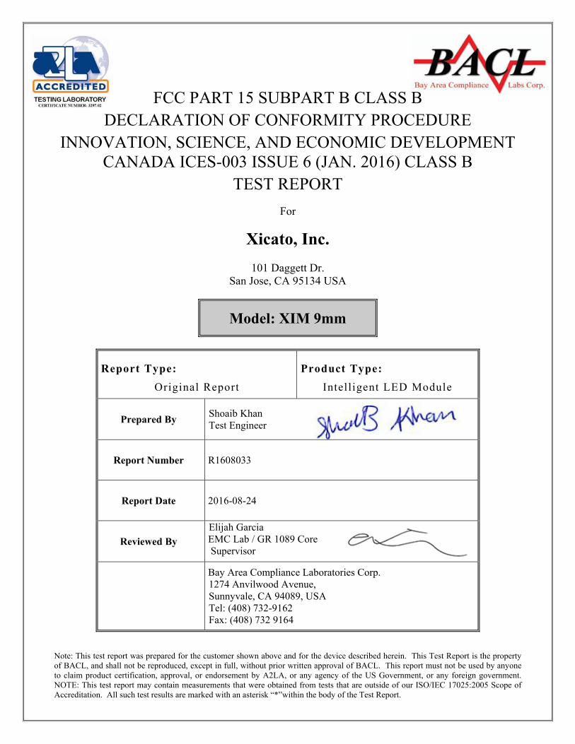
Note: This test report was prepared for the customer shown above and for the device described herein. This Test Report is the property of BACL, and shall not be reproduced, except in full, without prior written approval of BACL. This report must not be used by anyone to claim product certification, approval, or endorsement by A2LA, or any agency of the US Government, or any foreign government. NOTE: This test report may contain measurements that were obtained from tests that are outside of our ISO/IEC 17025:2005 Scope of Accreditation. All such test results are marked with an asterisk “*”within the body of the Test Report.
FCC PART 15 SUBPART B CLASS B DECLARATION OF CONFORMITY PROCEDURE
INNOVATION, SCIENCE, AND ECONOMIC DEVELOPMENT CANADA ICES-003 ISSUE 6 (JAN. 2016) CLASS B
TEST REPORT
For
Xicato, Inc.
101 Daggett Dr. San Jose, CA 95134 USA
Model: XIM 9mm
Report Type:
Original Report
Product Type:
Intelligent LED Module
Prepared By Shoaib Khan Test Engineer
Report Number R1608033
Report Date 2016-08-24
Reviewed By
Elijah Garcia EMC Lab / GR 1089 Core Supervisor
Bay Area Compliance Laboratories Corp. 1274 Anvilwood Avenue, Sunnyvale, CA 94089, USA Tel: (408) 732-9162 Fax: (408) 732 9164
Xicato, Inc. Model Number: XIM 9mm
Report Number: R1608033 Page 2 of 30 FCC 15B/ISED ICES-003 Test Report
TABLE OF CONTENTS
1 GENERAL INFORMATION ............................................................................................................................... 5
1.1 GENERAL STATEMENTS ..................................................................................................................................... 5 1.2 PURPOSE ............................................................................................................................................................ 5 1.3 AGENT FOR THE RESPONSIBLE PARTY ............................................................................................................... 5 1.4 RESPONSIBLE PARTY ......................................................................................................................................... 6 1.5 PRODUCT DESCRIPTION OF THE EQUIPMENT UNDER TEST (EUT) ...................................................................... 6 1.6 MECHANICAL DESCRIPTION OF THE EUT .......................................................................................................... 6 1.7 RELATED SUBMITTAL(S)/GRANT(S) ................................................................................................................... 6 1.8 TEST METHODOLOGY ........................................................................................................................................ 6 1.9 TEST FACILITY REGISTRATIONS ........................................................................................................................ 7 1.10 TEST FACILITY ACCREDITATIONS ...................................................................................................................... 7 1.11 MEASUREMENT UNCERTAINTIES ..................................................................................................................... 10
2 SYSTEM TEST CONFIGURATION ................................................................................................................ 11
2.1 JUSTIFICATION ................................................................................................................................................. 11 2.2 EUT EXERCISING SOFTWARE .......................................................................................................................... 11 2.3 EQUIPMENT MODIFICATIONS ........................................................................................................................... 11 2.4 SPECIAL EQUIPMENT ....................................................................................................................................... 11 2.5 EUT MODE OF OPERATION .............................................................................................................................. 11 2.6 METHOD OF MONITORING ............................................................................................................................... 11 2.7 LOCAL SUPPORT EQUIPMENT........................................................................................................................... 11 2.8 REMOTE SUPPORT EQUIPMENT ........................................................................................................................ 11 2.9 EUT INTERNAL CONFIGURATION DETAILS ...................................................................................................... 12 2.10 EXTERNAL I/O CABLING LIST AND DETAILS ................................................................................................... 12 2.11 EUT EXTERNAL POWER SUPPLY LIST AND DETAILS ....................................................................................... 12
3 SUMMARY OF TEST RESULTS ...................................................................................................................... 13
4 FCC §15.109 & ISED ICES-003 ISSUE 6 (JAN. 2016) – RADIATED EMISSIONS..................................... 14
4.1 APPLICABLE STANDARDS ................................................................................................................................ 14 4.2 TEST SETUP BLOCK DIAGRAM ......................................................................................................................... 17 4.3 CORRECTED AMPLITUDE AND MARGIN CALCULATIONS .................................................................................. 17 4.4 TEST EQUIPMENT LIST AND DETAILS .............................................................................................................. 18 4.5 EMI MEASUREMENT SOFTWARE ..................................................................................................................... 18 4.6 TEST ENVIRONMENTAL CONDITIONS & TEST PERSONNEL .............................................................................. 18 4.7 RADIATED EMISSIONS TEST PLOTS AND DATA ................................................................................................ 19 4.8 SUMMARY OF TEST RESULTS ........................................................................................................................... 21
5 EXHIBIT A – FCC AND INDUSTRY CANADA PRODUCT LABELING REQUIREMENTS ................. 22
5.1 AS PER FCC §15.19: LABELLING REQUIREMENTS PARAGRAPH 3 .................................................................... 22 5.2 AS PER ISED ICES-003 §8 LABELING REQUIREMENTS ................................................................................... 23 5.3 LABEL LOCATION ON EUT .............................................................................................................................. 23
6 EXHIBIT B- TEST SETUP PHOTOS ............................................................................................................... 24
6.1 RADIATED EMISSIONS ...................................................................................................................................... 24
7 EXHIBIT C- EUT PHOTOS ............................................................................................................................... 26
7.1 EUT FRONT VIEW ........................................................................................................................................... 26 7.2 EUT RIGHT VIEW ............................................................................................................................................ 26 7.3 EUT REAR VIEW ............................................................................................................................................. 27 7.4 EUT LEFT VIEW .............................................................................................................................................. 27 7.5 EUT STAND VIEW ........................................................................................................................................... 28 7.6 EUT LAMPSHADE FRONT VIEW ....................................................................................................................... 28 7.7 EUT LAMPSHADE BOTTOM VIEW .................................................................................................................... 29 7.8 MAIN EUT TOP VIEW ...................................................................................................................................... 29
Xicato, Inc. Model Number: XIM 9mm
Report Number: R1608033 Page 3 of 30 FCC 15B/ISED ICES-003 Test Report
7.9 MAIN EUT BOTTOM VIEW .............................................................................................................................. 30 7.10 EUT MAIN BOARD VIEW ................................................................................................................................. 30
Xicato, Inc. Model Number: XIM 9mm
Report Number: R1608033 Page 4 of 30 FCC 15B/ISED ICES-003 Test Report
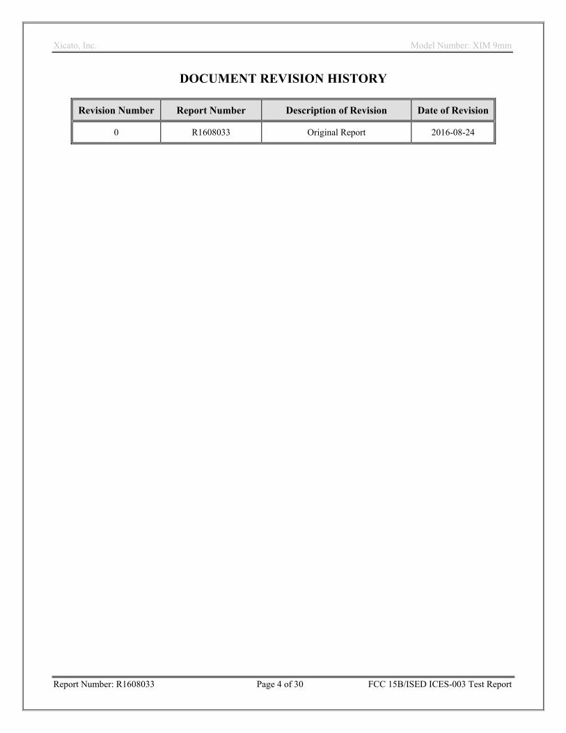
DOCUMENT REVISION HISTORY
Revision Number Report Number Description of Revision Date of Revision
0 R1608033 Original Report 2016-08-24
Xicato, Inc. Model Number: XIM 9mm
Report Number: R1608033 Page 5 of 30 FCC 15B/ISED ICES-003 Test Report
1 General Information
1.1 General Statements
Bay area Compliance Laboratory Corp. [BACL] hereby makes the following Statements:
The Unit(s) described in this Test Report were received at BACL’s facilities on 03 August 2016. Testing was performed on the Unit(s) described in this Test Report during the period 03 June 2016.
The Test Results reported herein apply only to the Unit(s) actually tested, and to substantially identical Units.
This Test Report must not be used to claim product endorsement by A2LA, or any agency of the U.S. Government, or by any other foreign government.
This Test Report is the property of BACL, and shall not be reproduced, except in full, without prior written approval of BACL.
1.2 Purpose
The purpose of this Test Report is to document the compliance of the product: Intelligent LED Module, model: XIM 9mm to the requirements of 47 CFR Part 15 Subpart B for Class B Devices and Innovation, Science, and Economic Development Canada ICES-003 Issue 6 (Jan. 2016) for Class B Devices. The objective of the testing performed was to determine the compliance of the EUT in accordance with the FCC Rules (i.e., 47 CFR Part 15 Subpart B Sections 15.107 and 15.109) using the CISPR 22 Edition 3 Class B limits for conducted and radiated emissions, ICES-003 Issue 6 (Jan. 2016) per Section 6.1 Table 2 for powerline conducted emissions limits; per Section 6.2.1 Table 5 for Radiated Emissions at frequencies below 1 GHz; and, per Section 6.2.2 Table 7 for Radiated Emissions at frequencies above 1 GHz, subject to the upper frequency limitations stated in Section 6.2 Table 3, using the test methods in the latest version of ANSI C63.4 (i.e., ANSI C63.4-2014). This Test Report references the applicable Electromagnetic Emissions requirements.
THE DATA CONTAINED IN THIS TEST REPORT WAS COLLECTED AND COMPILED BY: Shoaib Khan [Test Engineer] 1.3 Agent for the Responsible Party
None

Xicato, Inc. Model Number: XIM 9mm
Report Number: R1608033 Page 6 of 30 FCC 15B/ISED ICES-003 Test Report
1.4 Responsible Party
Company Name: Xicato, Inc. Contact: Robert Yang
Street Address: 101 Daggett Dr. City/State/Zip: San Jose, CA 95134 Country: USA
Telephone: +1-408-599-0448
Fax: +1-408-890-2817 (main)
E-mail: [email protected]
Web: http://www.xicato.com/ 1.5 Product Description of the Equipment under Test (EUT)
The “EUT” (Equipment under Test) was a LED light with integrated driver and Bluetooth communication 1.6 Mechanical Description of the EUT
Dimensions: approximately 9.0 cm (L) x 15.0cm (W) x 17.0 cm (H) Weight: approximately 0.75 kilogrammes. Serial Number: R1608033-01 (Note: The EUT was a pre-production prototype that had no Serial Number). EUT Photos: See Exhibit C of this Test Report. 1.7 Related Submittal(s)/Grant(s)
None 1.8 Test Methodology
All of the measurements contained in this Test Report were made in accordance with ANSI C63.4-2014 “American National Standard for Methods of Measurement of Radio-Noise Emissions from Low-Voltage Electrical and Electronic Equipment in the range of 9 kHz to 40 GHz”. All tests were performed at the Bay Area Compliance Laboratories Corp. facilities in Sunnyvale California.
Xicato, Inc. Model Number: XIM 9mm
Report Number: R1608033 Page 7 of 30 FCC 15B/ISED ICES-003 Test Report
1.9 Test Facility Registrations
BACLs test facilities that are used to perform Radiated and Conducted Emissions tests are currently recognized by the Federal Communications Commission as Accredited with NIST Designation Number US1129.
BACL’s test facilities that are used to perform Radiated and Conducted Emissions tests are currently registered with Industry Canada under Registration Numbers: 3062A-1, 3062A-2, and 3062A-3.
BACL is a Chinese Taipei Bureau of Standards Metrology and Inspection (BSMI) validated Conformity Assessment Body (CAB), under Appendix B, Phase I Procedures of the APEC Mutual Recognition Arrangement (MRA). BACL’s BSMI Lab Code Number is: SL2-IN-E-1002R
BACL’s test facilities that are used to perform AC Line Conducted Emissions, Telecommunications Line Conducted Emissions, Radiated Emissions from 30 MHz to 1 GHz, and Radiated Emissions from 1 GHz to 6 GHz are currently recognized as Accredited in accordance with the Voluntary Control Council for Interference [VCCI] Article 15 procedures under Registration Number A-0027. 1.10 Test Facility Accreditations
Bay Area Compliance Laboratories Corp. (BACL) is:
A- An independent, 3rd-Party, Commercial Test Laboratory accredited to ISO/IEC 17025:2005 by A2LA (Test Laboratory Accreditation Certificate Number 3279.02), in the fields of: Electromagnetic Compatibility and Telecommunications. Unless noted by an Asterisk (*) in the Compliance Matrix (See Section 3 of this Test Report), BACL’s ISO/IEC 17025:2005 Scope of Accreditation includes all of the Test Method Standards and/or the Product Family Standards detailed in this Test Report..
BACL’s ISO/IEC 17025:2005 Scope of Accreditation includes a comprehensive suite of EMC Emissions, EMC Immunity, Radio, RF Exposure, Safety and wireline Telecommunications test methods applicable to a wide range of product categories. These product categories include Central Office Telecommunications Equipment [including NEBS - Network Equipment Building Systems], Unlicensed and Licensed Wireless and RF devices, Information Technology Equipment (ITE); Telecommunications Terminal Equipment (TTE); Medical Electrical Equipment; Industrial, Scientific and Medical Test Equipment; Professional Audio and Video Equipment; Industrial and Scientific Instruments and Laboratory Apparatus; Cable Distribution Systems, and Energy Efficient Lighting. B- A Product Certification Body accredited to ISO/IEC 17065:2012 by A2LA (Product Certification Body Accreditation Certificate Number 3279.03) to certify - For the USA (Federal Communications Commission):
1- All Unlicensed radio frequency devices within FCC Scopes A1, A2, A3, and A4; 2- All Licensed radio frequency devices within FCC Scopes B1, B2, B3, and B4; 3- All Telephone Terminal Equipment within FCC Scope C.
- For the Canada (Industry Canada): 1 All Scope 1-Licence-Exempt Radio Frequency Devices; 2 All Scope 2-Licensed Personal Mobile Radio Services; 3 All Scope 3-Licensed General Mobile & Fixed Radio Services; 4 All Scope 4-Licensed Maritime & Aviation Radio Services; 5 All Scope 5-Licensed Fixed Microwave Radio Services 6 All Broadcasting Technical Standards (BETS) in the Category I Equipment Standards List.
- For Singapore (Info-Communications Development Authority (IDA)):
Xicato, Inc. Model Number: XIM 9mm
Report Number: R1608033 Page 8 of 30 FCC 15B/ISED ICES-003 Test Report
1 All Line Terminal Equipment: All Technical Specifications for Line Terminal Equipment – Table 1 of IDA MRA Recognition Scheme: 2011, Annex 2
2. All Radio-Communication Equipment: All Technical Specifications for Radio-Communication Equipment – Table 2 of IDA MRA Recognition Scheme: 2011, Annex 2
- For the Hong Kong Special Administrative Region: 1 All Radio Equipment, per KHCA 10XX-series Specifications; 2 All GMDSS Marine Radio Equipment, per HKCA 12XX-series Specifications; 3 All Fixed Network Equipment, per HKCA 20XX-series Specifications.
- For Japan: 1 MIC Telecommunication Business Law (Terminal Equipment):
- All Scope A1 - Terminal Equipment for the Purpose of Calls; - All Scope A2 - Other Terminal Equipment
2 Radio Law (Radio Equipment): - All Scope B1 - Specified Radio Equipment specified in Article 38-2-2, paragraph 1, item 1 of
the Radio Law - All Scope B2 - Specified Radio Equipment specified in Article 38-2-2, paragraph 1, item 2 of
the Radio Law - All Scope B3 - Specified Radio Equipment specified in Article 38-2-2, paragraph 1, item 3 of
the Radio Law
C- A Product Certification Body accredited to ISO/IEC 17065:2012 by A2LA (Product Certification Body Accreditation Certificate Number 3279.01) to certify Products to USA’s Environmental Protection Agency (EPA) ENERGY STAR Product Specifications for:
1 Electronics and Office Equipment: - for Telephony (ver. 3.0) - for Audio/Video (ver. 3.0) - for Battery Charging Systems (ver. 1.1) - for Set-top Boxes & Cable Boxes (ver. 4.1) - for Televisions (ver. 6.1) - for Computers (ver. 6.0) - for Displays (ver. 6.0) - for Imaging Equipment (ver. 2.0) - for Computer Servers (ver. 2.0)
2 Commercial Food Service Equipment - for Commercial Dishwashers (ver. 2.0) - for Commercial Ice Machines (ver. 2.0) - for Commercial Ovens (ver. 2.1) - for Commercial Refrigerators and Freezers
3 Lighting Products - For Decorative Light Strings (ver. 1.5) - For Luminaires (including sub-components) and Lamps (ver. 1.2) - For Compact Fluorescent Lamps (CFLs) (ver. 4.3) - For Integral LED Lamps (ver. 1.4)
4 Heating, Ventilation, and AC Products - for Residential Ceiling Fans (ver. 3.0) - for Residential Ventilating Fans (ver. 3.2)
5 Other - For Water Coolers (ver. 3.0)

Xicato, Inc. Model Number: XIM 9mm
Report Number: R1608033 Page 9 of 30 FCC 15B/ISED ICES-003 Test Report
D- A NIST Designated Phase-I and Phase-II Conformity Assessment Body (CAB) for the following economies and regulatory authorities under the terms of the stated MRAs/Treaties:
- Australia: ACMA (Australian Communication and Media Authority) – APEC Tel MRA -Phase I; - Canada: (Industry Canada - IC) Foreign Certification Body – FCB – APEC Tel MRA -Phase I & Phase II; - Chinese Taipei (Republic of China – Taiwan):
o BSMI (Bureau of Standards, Metrology and Inspection) APEC Tel MRA -Phase I; o NCC (National Communications Commission) APEC Tel MRA -Phase I;
- European Union: o EMC Directive 2004/108/EC US-EU EMC & Telecom MRA CAB o Radio & Teleterminal Equipment (R&TTE) Directive 1995/5/EC
US -EU EMC & Telecom MRA CAB - Hong Kong Special Administrative Region: (Office of the Telecommunications Authority – OFTA)
APEC Tel MRA -Phase I & Phase II - Israel – US-Israel MRA Phase I - Republic of Korea (Ministry of Communications - Radio Research Laboratory) APEC Tel MRA -Phase I - Singapore: (Infocomm Development Authority - IDA) APEC Tel MRA -Phase I & Phase II; - Japan: VCCI - Voluntary Control Council for Interference US-Japan Telecom Treaty VCCI Side Letter- - USA:
o ENERGY STAR Recognized Test Laboratory – US EPA o Telecommunications Certification Body (TCB) – US FCC;
- Vietnam: APEC Tel MRA -Phase I;

Xicato, Inc. Model Number: XIM 9mm
Report Number: R1608033 Page 10 of 30 FCC 15B/ISED ICES-003 Test Report
1.11 Measurement Uncertainties
All measurements involve uncertainties. In the case of EMC Emissions tests, the influence quantities (factors) that make a significant contribution to the measurement uncertainties are detailed in the latest version of CISPR 16-4-2 “Specification for radio disturbance and immunity measuring apparatus and methods – Part 4-2: Uncertainties, statistics and limit modelling – Measurement instrumentation uncertainty” (i.e., CISPR 16-4-2:2011-06 + C1:2013-04 +A1:2014-02).
Based on the uncertainty models given in the latest version of CISPR 16-4-2, and, based on the calibration uncertainties of the specific instruments and facilities used at BACL to perform the measurements documented in this Test Report, the following estimates have been made of BACL’s Measurement Uncertainties for the measurements documented in this Test Report.
Type of Measurement BACL Typical ULAB Value (for a k=2 Coverage Factor, equivalent to ~ 95% level of confidence)
UCISPR Value worst-allowable values, per Table 1 of the latest version of CISPR 16-4-2 (for a k=2 Coverage Factor, equivalent to ~ 95% level of confidence)
Conducted Disturbance (Mains Port) 150 kHz to 30 MHz (i.e., AC/DC Line Conducted Emissions measurements made with a Fischer FCC-LISN-50-25-2-10 LISN)
2.26
3.44 dB
Radiated Electric Field Disturbance – Horizontal Polarization, 30 MHz – 200 MHz (i.e., Radiated Emissions measured at 10 metres distance)
4.21 dB
5.05 dB
Radiated Electric Field Disturbance – Vertical Polarization, 30 MHz – 200 MHz (i.e., Radiated Emissions measured at 10 metres distance)
4.07 dB
5.03 dB
Radiated Electric Field Disturbance – Horizontal Polarization, 200 MHz – 1000 MHz (i.e., Radiated Emissions at 10 metres distance)
4.17 dB
5.21 dB
Radiated Electric Field Disturbance – Vertical Polarization, 200 MHz – 1000 MHz z (i.e., Radiated Emissions measured at 10 metres distance)
4.46 dB
5.22 dB
Radiated Electric Field Disturbance Horizontal & Vertical Polarizations, 1 GHz – 6 GHz (i.e., Radiated Emissions measured at 3 metres distance)
4.62 dB (With Boresighting)
UCISPR Value is Not Specified
Radiated Electric Field Disturbance Horizontal & Vertical Polarizations, 6 GHz – 18 GHz (i.e., Radiated Emissions measured at 3 metres distance)
4.67 dB (With Boresighting)
UCISPR Value is Not Specified

Xicato, Inc. Model Number: XIM 9mm
Report Number: R1608033 Page 11 of 30 FCC 15B/ISED ICES-003 Test Report
2 System Test Configuration
2.1 Justification
The EUT and its Support Equipment were configured as a system and were arranged in accordance with the ANSI C63.4-2014 Standard. 2.2 EUT Exercising Software
The software (XIMtroller) used was provided by Robert Yang and was GUI based featuring Microsoft Windows and Apple IOS. 2.3 Equipment Modifications
None 2.4 Special Equipment
None 2.5 EUT Mode of Operation
The EUT was emitting light at Full intensity powered by 48 V DC. 2.6 Method of Monitoring
Power on; connect to EUT and verify communication.
2.7 Local Support Equipment
The following items of Support Equipment were located locally (i.e., within the Semi-Anechoic Chamber):
Manufacturer Description Model Serial Number
ROAL living Energy AC/DC Power Supply Strato RSLP035-48 323K0A73214A000047
Apple Cell phone iPhone SE -
2.8 Remote Support Equipment
None
Xicato, Inc. Model Number: XIM 9mm
Report Number: R1608033 Page 12 of 30 FCC 15B/ISED ICES-003 Test Report
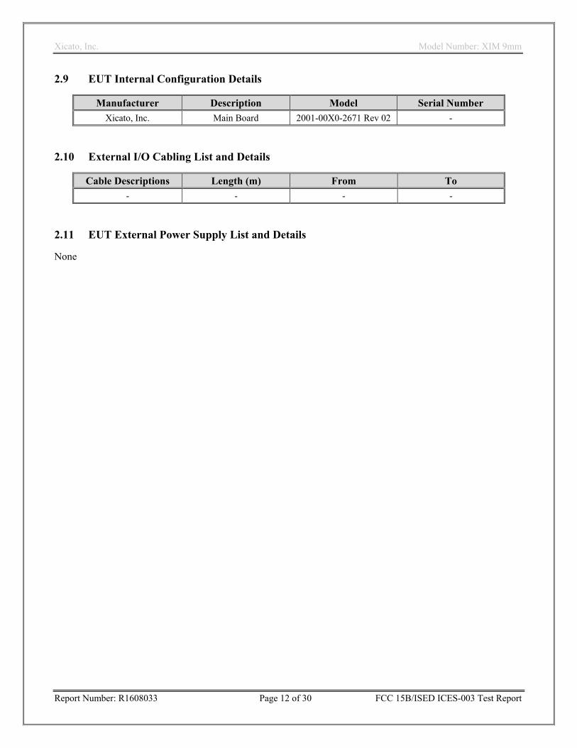
2.9 EUT Internal Configuration Details
Manufacturer Description Model Serial Number
Xicato, Inc. Main Board 2001-00X0-2671 Rev 02 -
2.10 External I/O Cabling List and Details
Cable Descriptions Length (m) From To
- - - -
2.11 EUT External Power Supply List and Details
None

Xicato, Inc. Model Number: XIM 9mm
Report Number: R1608033 Page 13 of 30 FCC 15B/ISED ICES-003 Test Report
3 Summary of Test Results
FCC (47 CFR Part 15 Subpart B) & ISED ICES-003 Issue 6 (Jan. 2016)
RULES Descriptions of Test Result(s)
FCC §15.107 & ISED ICES-003 Issue 6 (Jan. 2016) Section 6.1 Table 2
Conducted Emissions N/A
FCC §15.109 & ISED ICES-003 Issue 6 (Jan. 2016) Section 6.2.2 Table 7
Radiated Emissions Pass
N/A: The EUT is DC powered.

Xicato, Inc. Model Number: XIM 9mm
Report Number: R1608033 Page 14 of 30 FCC 15B/ISED ICES-003 Test Report
4 FCC §15.109 & ISED ICES-003 Issue 6 (Jan. 2016) – Radiated Emissions
4.1 Applicable Standards
As per FCC §15.109: Radiated Emission Limits
a) Except for Class A digital devices, the field strength of radiated emissions from unintentional radiators at a distance of 3 meters shall not exceed the following values:
Frequency of emission (MHz) Field strength (microvolts/meter)
30-88 100
88-216 150
216-960 200
Above 960 500
(g) As an alternative to the radiated emission limits shown in paragraphs (a) and (b) of this section, digital devices may be shown to comply with the standards contained in Third Edition of the International Special Committee on Radio Interference (CISPR), Pub. 22, “Information Technology Equipment—Radio Disturbance Characteristics—Limits and Methods of Measurement” (incorporated by reference, see §15.38). In addition:
(1) The test procedure and other requirements specified in this part shall continue to apply to digital devices.
(2) If, in accordance with §15.33 of this part, measurements must be performed above 1000 MHz, compliance above 1000 MHz shall be demonstrated with the emission limit in paragraph (a) or (b) of this section, as appropriate. Measurements above 1000 MHz may be performed at the distance specified in the CISPR 22 publications for measurements below 1000 MHz provided the limits in paragraphs (a) and (b) of this section are extrapolated to the new measurement distance using an inverse linear distance extrapolation factor (20 dB/decade), e.g., the radiated limit above 1000 MHz for a Class B digital device is 150 μV/m, as measured at a distance of 10 meters.
(3) The measurement distances shown in CISPR Pub. 22, including measurements made in accordance with this paragraph above 1000 MHz, are considered, for the purpose of §15.31(f)(4) of this part, to be the measurement distances specified in this part.
Note: The CISPR 22 Third Edition Class B Radiated Emissions Limits were applied from 30 MHz to 1 GHz (i.e., from 30 MHz to 230 MHz, a Limit of 30 dBµV/m was applied at a 10 m measurement distance; from 230 MHz to 1000 MHz, a 37 dBµV/m limit was applied at a 10 m measurement distance). Above 1000 MHz the FCC limit of 500 μV/m (54 dBµV/m) was applied at a 3 m measurement distance.

Xicato, Inc. Model Number: XIM 9mm
Report Number: R1608033 Page 15 of 30 FCC 15B/ISED ICES-003 Test Report
As per the Innovation, Science, and Economic Development Canada ICES-003 Issue 6 (Jan. 2016) Section 6.2 Table 3 Frequency Limits for Radiated Emissions:
Radiated emissions from an ITE shall be measured from the lowest frequency generated, or used, in the device or 30 MHz, whichever is higher, up to the frequency determined in accordance with Table 3.
Table 3 – Frequency Range of Measurement Highest Frequency Generated or Used in Device
Upper Frequency of Radiated Measurement
Below 1.705 MHz No radiated testing required 1.705 MHz – 108 MHz 1 GHz 108 MHz – 500 MHz 2 GHz
500 MHz – 1 GHz 5 GHz
Above 1 GHz 5th harmonic of the highest frequency or 40 GHz,
whichever is lower.
At frequencies at or above 30 MHz, measurements may be performed at a distance other than what is specified in this Section. Measurements are not made in the near field except where it can be shown that near field measurements are appropriate due to the characteristics of the device; and it can be demonstrated that the signal levels needed to be measured at the distance employed can be detected by the measurement equipment. Measurements shall not be performed at a distance greater than 30 meters unless it can be demonstrated that measurements at a distance of 30 meters or less are not practical. When performing measurements at a distance other than that specified, the results shall be extrapolated to the specified distance using an extrapolation factor of 20 dB per decade (inverse linear-distance for field strength measurements).
As per the Innovation, Science, and Economic Development Canada ICES-003 Issue 6 (Jan. 2016) Section 5(a) (ii) (i.e., CAN/CSA-CISPR 22-10 Class B Radiated Emissions Limits:
CAN/CSA-CISPR 22-10 Class B Radiated Emissions Limits as stated in Table 6 – Limits for radiated disturbance of class B ITE at a measuring distance of 10 m
Frequency (MHz) Class B Radiated Limit (dBμV/m)
Quasi-Peak Detector 30 to 230 30
230 to 1000 37 NOTE 1 The lower limit shall apply at the transition frequency. NOTE 2 Additional provisions may be required for cases where interference occur

Xicato, Inc. Model Number: XIM 9mm
Report Number: R1608033 Page 16 of 30 FCC 15B/ISED ICES-003 Test Report
As per the Innovation, Science, and Economic Development Canada ICES-003 Issue 6 (Jan. 2016) Section 6.2.2 Table 7 Class B Radiated Emissions Limits above 1 GHz:
Class B: An ITE that does not meet the conditions for Class A equipment shall comply with the Class B radiated limits set out in Table 7 determined at a distance of 3 meters.
Table 7 – Class B Radiated Limits above 1 GHz Frequency (MHz)
Frequency (MHz) Class B Radiated Limit (dBμV/m)
Linear Average Detector Peak Detector
> 1000 54 74
The radiated emissions tests were performed in the BACL 10-meter Anechoic Chamber, using a test setup in accordance with ANSI C63.4-2014 measurement procedures.
SPECIAL NOTE: A “Boresight Mast” was used to ensure that the emissions from the EUT remained within the 3 dB Beamwidth of the Double-Ridge Guide Horn Antenna used to make measurements above 1 GHz. Additionally, at frequencies above 1 GHz, loose-laid RF Absorber was placed on the Chamber Ground Plane to ensure that those measurements were made under conditions that approximated free-space.
The spacing between the peripherals (if any) was 10 cm. The external I/O cables (if any) were draped along the test table and bundled as required.
The procedures detailed in ANSI C63.4-2014 Clauses 8.3.1 and 11.9.2, were used to determine the mode of operation and cable positions of the EUT system that produce the emissions with the highest amplitudes relative to the limit. This arrangement was used when the final ac radiated emissions measurements were made on the EUT.
Using the mode of operation and cable position arrangement of the EUT system determined in ANSI C63.4-2014 Clause 8.3.1, the procedure detailed in ANSI C63.4-2014 Clause 11.9.3 was used to perform the final radiated emission measurements. In particular, the six highest emissions relative to the limit in the frequency range were recorded.
It should be noted that, in addition to cable manipulations, a maximizing procedure that included varying the receive antenna height and the turntable azimuth was employed while making all final compliance measurements on the EUT.
All measurement data was initially collected and recorded under computer control using the VASONA® EMI
Software package, with the EMI Receiver/Spectrum Analyzer in Peak Detection mode. From 30 MHz to 1 GHz, Quasi-peak measurements were made only when a Peak emission was found to be - 6 dB or higher with respect to the applicable specification limits. Above 1 GHz, both Peak and CISPR (Linear) Average measurement were collected and recorded under computer control using the VASONA®
EMI Software package.
Xicato, Inc. Model Number: XIM 9mm
Report Number: R1608033 Page 17 of 30 FCC 15B/ISED ICES-003 Test Report
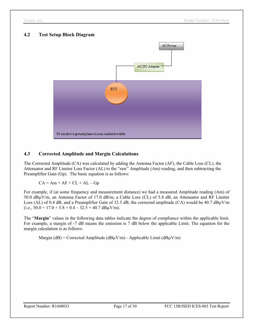
4.2 Test Setup Block Diagram
4.3 Corrected Amplitude and Margin Calculations
The Corrected Amplitude (CA) was calculated by adding the Antenna Factor (AF), the Cable Loss (CL), the Attenuator and RF Limiter Loss Factor (AL) to the “raw” Amplitude (Am) reading, and then subtracting the Preamplifier Gain (Gp). The basic equation is as follows:
CA = Am + AF + CL + AL – Gp
For example, if (at some frequency and measurement distance) we had a measured Amplitude reading (Am) of 50.0 dBµV/m, an Antenna Factor of 17.0 dB/m, a Cable Loss (CL) of 5.8 dB, an Attenuator and RF Limiter Loss (AL) of 0.4 dB, and a Preamplifier Gain of 32.5 dB, the corrected amplitude (CA) would be 40.7 dBµV/m (i.e., 50.0 + 17.0 + 5.8 + 0.4 – 32.5 = 40.7 dBµV/m). The “Margin” values in the following data tables indicate the degree of compliance within the applicable limit. For example, a margin of -7 dB means the emission is 7 dB below the applicable Limit. The equation for the margin calculation is as follows:
Margin (dB) = Corrected Amplitude (dBµV/m) - Applicable Limit (dBµV/m)
Xicato, Inc. Model Number: XIM 9mm
Report Number: R1608033 Page 18 of 30 FCC 15B/ISED ICES-003 Test Report
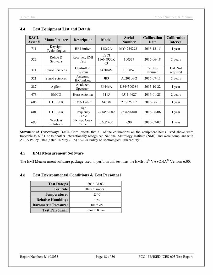
4.4 Test Equipment List and Details
BACL Asset #
Manufacturer Description Model Serial
Number Calibration
Date Calibration
Interval
711 Keysight
Technologies RF Limiter 11867A MY42242931 2015-12-15 1 year
322 Rohde & Schwarz
Receiver, EMI Test
ESCI 1166.5950K
03 100337 2015-06-18 2 years
311 Sunol Sciences Controller,
System SC104V 113005-1
Cal. Not required
Cal. Not required
321 Sunol Sciences Antenna,
BiConiLog JB3 A020106-2 2015-07-11 2 years
287 Agilent Analyzer, Spectrum
E4446A US44300386 2015-10-22 1 year
473 EMCO Horn Antenna 3115 9511-4627 2016-01-28 2 years
606 UTiFLEX SMA Cable 64638 218625007 2016-06-17 1 year
601 UTiFLEX High
Frequency Cable
223458-002 223458-001 2016-06-06 1 year
690 Wireless Solutions
N-Type Coax Cable
LMR 400 690 2015-07-02 1 year
Statement of Traceability: BACL Corp. attests that all of the calibrations on the equipment items listed above were traceable to NIST or to another internationally recognized National Metrology Institute (NMI), and were compliant with A2LA Policy P102 (dated 14 May 2015) “A2LA Policy on Metrological Traceability”. 4.5 EMI Measurement Software
The EMI Measurement software package used to perform this test was the EMIsoft® VASONA® Version 6.00. 4.6 Test Environmental Conditions & Test Personnel
Test Date(s) 2016-08-03
Test Site 10m Chamber 1
Temperature: 23º C
Relative Humidity: 44%
Barometric Pressure: 101.7 kPa
Test Personnel: Shoaib Khan
Xicato, Inc. Model Number: XIM 9mm
Report Number: R1608033 Page 19 of 30 FCC 15B/ISED ICES-003 Test Report
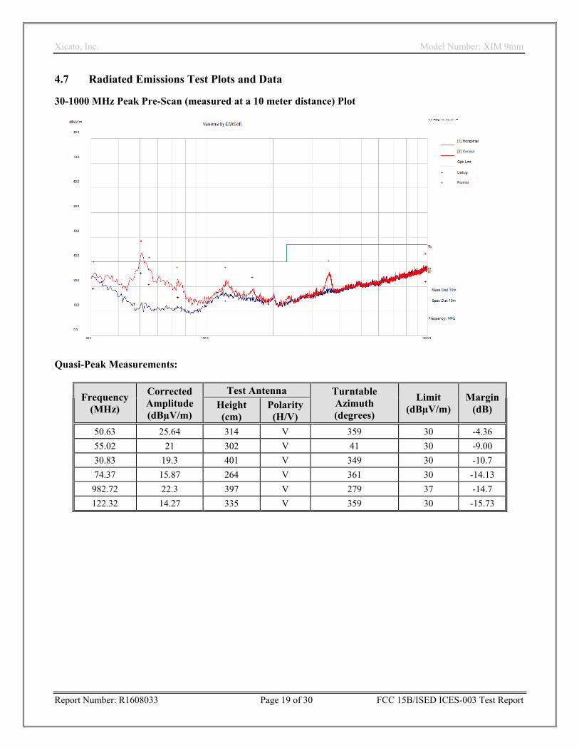
4.7 Radiated Emissions Test Plots and Data
30-1000 MHz Peak Pre-Scan (measured at a 10 meter distance) Plot
Quasi-Peak Measurements:
Frequency (MHz)
Corrected Amplitude (dBµV/m)
Test Antenna Turntable Azimuth (degrees)
Limit (dBµV/m)
Margin(dB) Height
(cm) Polarity (H/V)
50.63 25.64 314 V 359 30 -4.36
55.02 21 302 V 41 30 -9.00
30.83 19.3 401 V 349 30 -10.7
74.37 15.87 264 V 361 30 -14.13
982.72 22.3 397 V 279 37 -14.7
122.32 14.27 335 V 359 30 -15.73
Xicato, Inc. Model Number: XIM 9mm
Report Number: R1608033 Page 20 of 30 FCC 15B/ISED ICES-003 Test Report
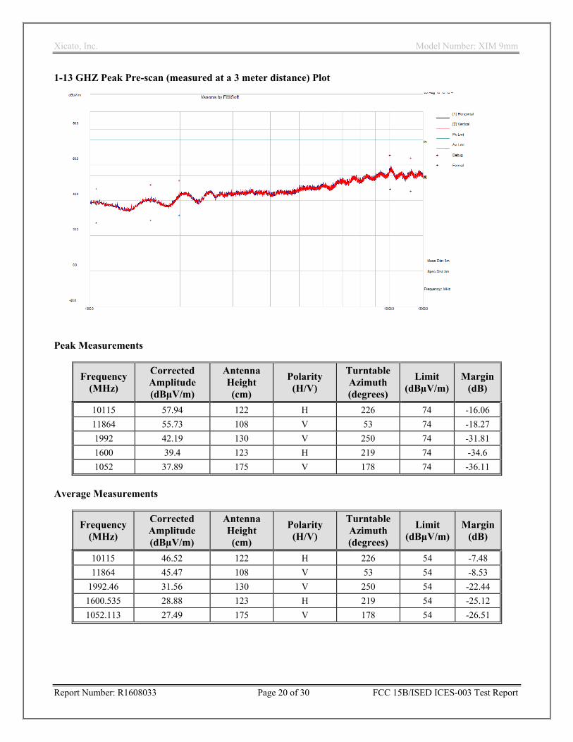
1-13 GHZ Peak Pre-scan (measured at a 3 meter distance) Plot
Peak Measurements
Frequency (MHz)
Corrected Amplitude (dBµV/m)
Antenna Height (cm)
Polarity (H/V)
Turntable Azimuth (degrees)
Limit (dBµV/m)
Margin(dB)
10115 57.94 122 H 226 74 -16.06
11864 55.73 108 V 53 74 -18.27
1992 42.19 130 V 250 74 -31.81
1600 39.4 123 H 219 74 -34.6
1052 37.89 175 V 178 74 -36.11
Average Measurements
Frequency (MHz)
Corrected Amplitude (dBµV/m)
Antenna Height (cm)
Polarity (H/V)
Turntable Azimuth (degrees)
Limit (dBµV/m)
Margin(dB)
10115 46.52 122 H 226 54 -7.48
11864 45.47 108 V 53 54 -8.53
1992.46 31.56 130 V 250 54 -22.44
1600.535 28.88 123 H 219 54 -25.12
1052.113 27.49 175 V 178 54 -26.51
Xicato, Inc. Model Number: XIM 9mm
Report Number: R1608033 Page 21 of 30 FCC 15B/ISED ICES-003 Test Report
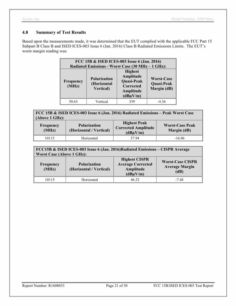
4.8 Summary of Test Results
Based upon the measurements made, it was determined that the EUT complied with the applicable FCC Part 15 Subpart B Class B and ISED ICES-003 Issue 6 (Jan. 2016) Class B Radiated Emissions Limits. The EUT’s worst margin reading was:
FCC 15B & ISED ICES-003 Issue 6 (Jan. 2016) Radiated Emissions - Worst Case (30 MHz – 1 GHz):
Frequency (MHz)
Polarization (Horizontal
Vertical)
Highest Amplitude Quasi-Peak Corrected Amplitude (dBµV/m)
Worst-Case Quasi-Peak Margin (dB)
50.63 Vertical 359 -4.36
FCC 15B & ISED ICES-003 Issue 6 (Jan. 2016) Radiated Emissions – Peak Worst Case (Above 1 GHz):
Frequency (MHz)
Polarization (Horizontal / Vertical)
Highest Peak Corrected Amplitude
(dBµV/m)
Worst-Case Peak Margin (dB)
10115 Horizontal 57.94 -16.06
FCC15B & ISED ICES-003 Issue 6 (Jan. 2016)Radiated Emissions – CISPR Average Worst Case (Above 1 GHz):
Frequency (MHz)
Polarization (Horizontal / Vertical)
Highest CISPR Average Corrected
Amplitude (dBµV/m)
Worst-Case CISPR Average Margin
(dB)
10115 Horizontal 46.52 -7.48
Xicato, Inc. Model Number: XIM 9mm
Report Number: R1608033 Page 22 of 30 FCC 15B/ISED ICES-003 Test Report
5 Exhibit A – FCC and Industry Canada Product Labeling Requirements
5.1 As per FCC §15.19: Labelling Requirements Paragraph 3
(3) All other devices shall bear the following statement in a conspicuous location on the device: This device complies with part 15 of the FCC Rules. Operation is subject to the following two conditions: (1) This device may not cause harmful interference, and (2) this device must accept any interference received, including interference that may cause undesired operation.
Specifications: Text is white in color and is left justified. Labels are printed in indelible ink on permanent adhesive backing or silk-screened and shall be affixed at a conspicuous location on the EUT. As per FCC §15.105: Information to the User
(b) For a Class B digital device or peripheral, the instructions furnished the user shall include the following or similar statement, placed in a prominent location in the text of the manual:
NOTE: This equipment has been tested and found to comply with the limits for a Class B digital device, pursuant to part 15 of the FCC Rules. These limits are designed to provide reasonable protection against harmful interference in a residential installation. This equipment generates, uses and can radiate radio frequency energy and, if not installed and used in accordance with the instructions, may cause harmful interference to radio communications. However, there is no guarantee that interference will not occur in a particular installation. If this equipment does cause harmful interference to radio or television reception, which can be determined by turning the equipment off and on, the user is encouraged to try to correct the interference by one or more of the following measures:
—Reorient or relocate the receiving antenna.
—Increase the separation between the equipment and receiver.
—Connect the equipment into an outlet on a circuit different from that to which the receiver is connected.
—Consult the dealer or an experienced radio/TV technician for help.
Trade Name Model Number

Xicato, Inc. Model Number: XIM 9mm
Report Number: R1608033 Page 23 of 30 FCC 15B/ISED ICES-003 Test Report
5.2 As per ISED ICES-003 §8 Labeling Requirements
The manufacturer, importer or supplier shall meet the labeling requirements set out in this section and in Notice 2014-DRS1003 for electronic labelling for every unit
(i) Prior to marketing in Canada, for ITE manufactured in Canada, and; (ii) Prior to importation into Canada, for imported ITE.
Each unit of an ITE model shall bear a label (see below) that represents the manufacturer’s or the importer’s SDoC with Innovation, Science and Economic Development Canada’s ICES-003. This label shall be permanently affixed to the ITE or displayed electronically and its text must be clearly legible. If the dimensions of the device are too small or if it is not practical to place the label on the ITE and electronic labelling has not been implemented, the label shall be, upon agreement with Innovation, Science and Economic Development Canada, placed in a prominent location in the user manual supplied with the ITE. The user manual may be in an electronic format and must be readily available. As per ISED ICES-003 §8 Innovation, Science, and Economic Development Canada ICES-003 Compliance Label:
CAN ICES-3 (B)/NMB-3(B) 5.3 Label Location on EUT
Xicato, Inc. Model Number: XIM 9mm
Report Number: R1608033 Page 24 of 30 FCC 15B/ISED ICES-003 Test Report
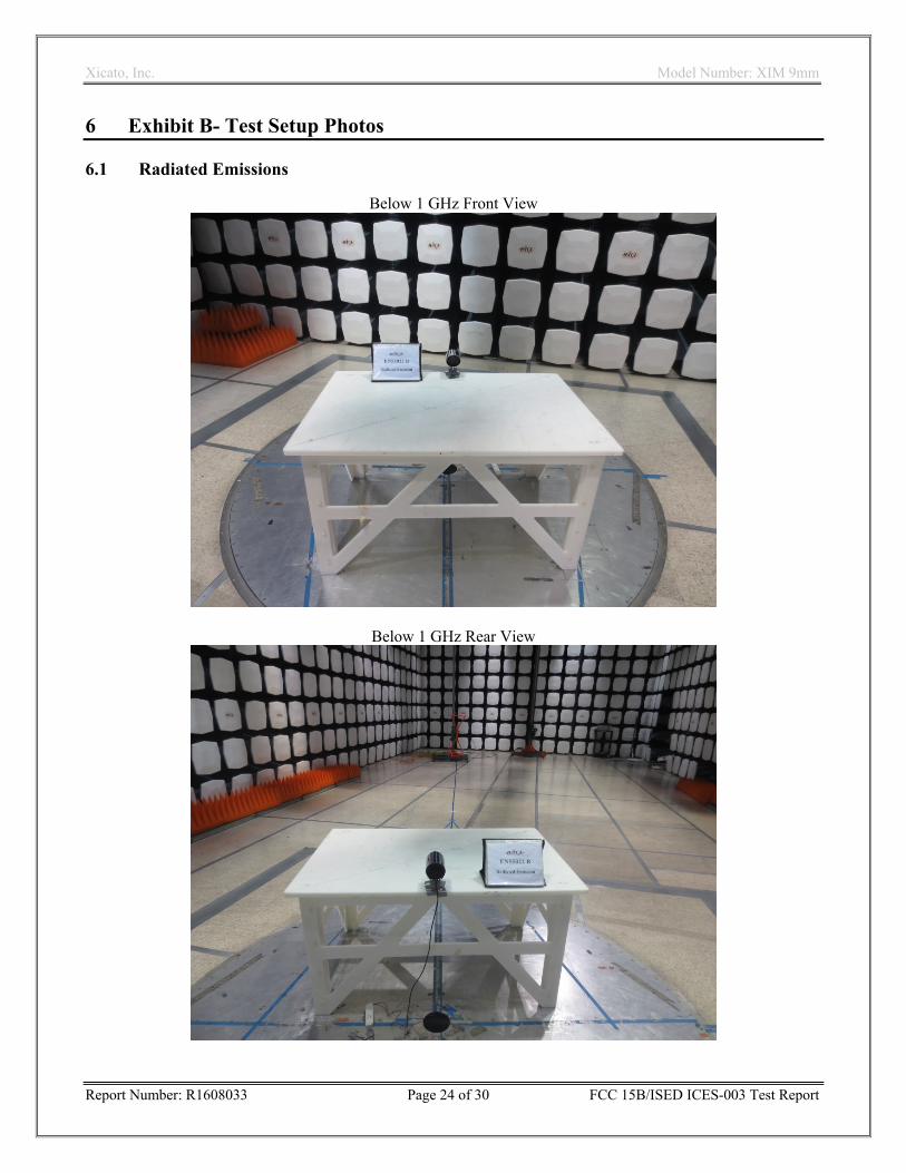
6 Exhibit B- Test Setup Photos
6.1 Radiated Emissions
Below 1 GHz Front View
Below 1 GHz Rear View
Xicato, Inc. Model Number: XIM 9mm
Report Number: R1608033 Page 25 of 30 FCC 15B/ISED ICES-003 Test Report
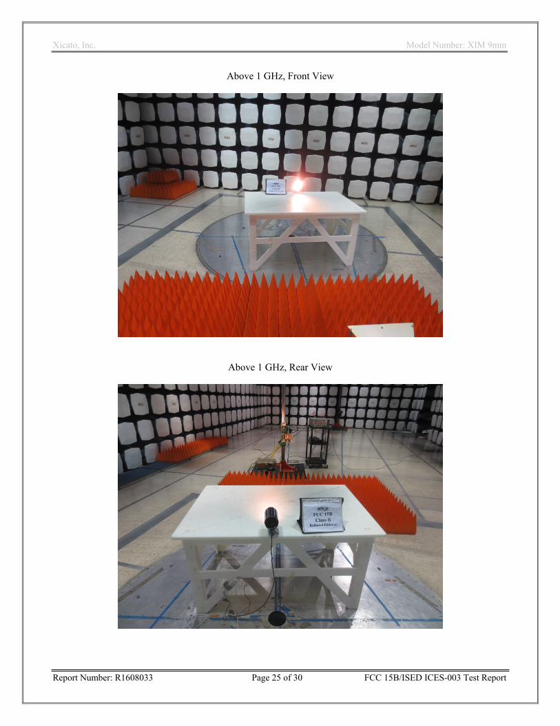
Above 1 GHz, Front View
Above 1 GHz, Rear View
Xicato, Inc. Model Number: XIM 9mm
Report Number: R1608033 Page 26 of 30 FCC 15B/ISED ICES-003 Test Report
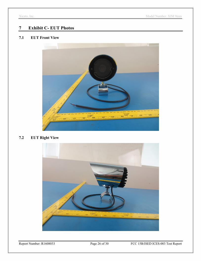
7 Exhibit C- EUT Photos
7.1 EUT Front View
7.2 EUT Right View
Xicato, Inc. Model Number: XIM 9mm
Report Number: R1608033 Page 27 of 30 FCC 15B/ISED ICES-003 Test Report
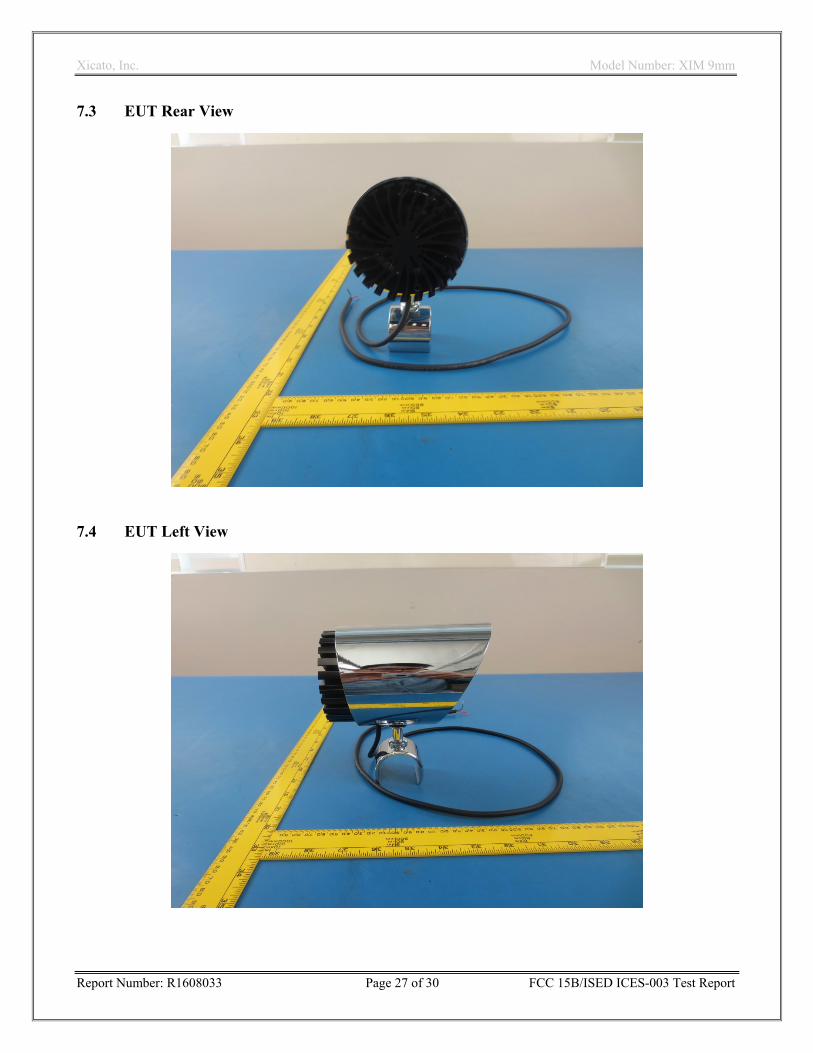
7.3 EUT Rear View
7.4 EUT Left View

Xicato, Inc. Model Number: XIM 9mm
Report Number: R1608033 Page 28 of 30 FCC 15B/ISED ICES-003 Test Report
7.5 EUT Stand View
7.6 EUT Lampshade Front View
Xicato, Inc. Model Number: XIM 9mm
Report Number: R1608033 Page 29 of 30 FCC 15B/ISED ICES-003 Test Report
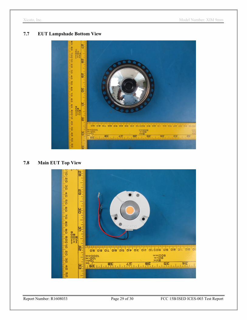
7.7 EUT Lampshade Bottom View
7.8 Main EUT Top View
Xicato, Inc. Model Number: XIM 9mm
Report Number: R1608033 Page 30 of 30 FCC 15B/ISED ICES-003 Test Report
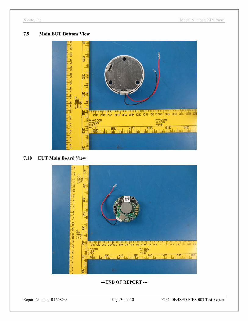
7.9 Main EUT Bottom View
7.10 EUT Main Board View
---END OF REPORT ---


![s=]p=U[=* XIm=d< B=g=v=d](https://img.pdfslide.net/doc/110x75/5ab70f9e7f8b9ab7638e6719/spu-ximd-bgvdgit-er-mipupk-nmk-xk-bjye-xe-qnu.jpg)