Embed Size (px)
Citation preview
7/23/2019 FCC Profitability Assessment via Advanced Modeling
http://slidepdf.com/reader/full/fcc-profitability-assessment-via-advanced-modeling 1/10
FCC profitability assessment viaadvanced modelling
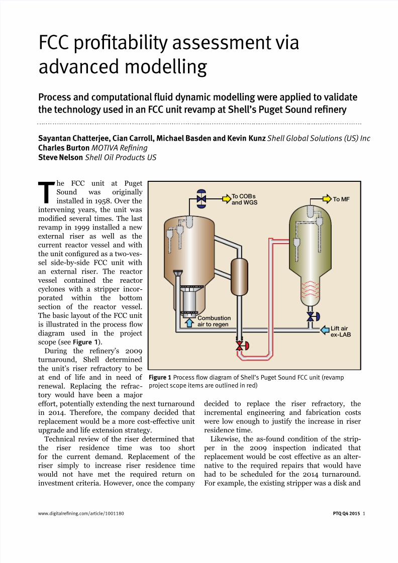
The FCC unit at Puget
Sound was originally
installed in 1958. Over theintervening years, the unit was
modied several times. The last
revamp in 1999 installed a new
external riser as well as the
current reactor vessel and with
the unit congured as a two-ves-
sel side-by-side FCC unit with
an external riser. The reactor
vessel contained the reactor
cyclones with a stripper incor-
porated within the bottomsection of the reactor vessel.
The basic layout of the FCC unit
is illustrated in the process ow
diagram used in the project
scope (see Figure 1).
During the renery’s 2009
turnaround, Shell determined
the unit’s riser refractory to be
at end of life and in need of
renewal. Replacing the refrac-
tory would have been a majoreffort, potentially extending the next turnaround
in 2014. Therefore, the company decided that
replacement would be a more cost-effective unit
upgrade and life extension strategy.
Technical review of the riser determined that
the riser residence time was too short
for the current demand. Replacement of the
riser simply to increase riser residence time
would not have met the required return on
investment criteria. However, once the company
Sayantan Chatterjee, Cian Carroll, Michael Basden and Kevin Kunz Shell Global Solutions (US) Inc Charles Burton MOTIVA RefiningSteve Nelson Shell Oil Products US
decided to replace the riser refractory, the
incremental engineering and fabrication costs
were low enough to justify the increase in riser
residence time.
Likewise, the as-found condition of the strip-
per in the 2009 inspection indicated that
replacement would be cost effective as an alter-
native to the required repairs that would have
had to be scheduled for the 2014 turnaround.
For example, the existing stripper was a disk and
www.digitalrefining.com/article/1001180 PTQ Q4 2015 1
Process and computational fluid dynamic modelling were applied to validatethe technology used in an FCC unit revamp at Shell’s Puget Sound refinery
To COBsand WGS
Lift airex-LAB
Combustionair to regen
To MF
Figure 1 Process flow diagram of Shell’s Puget Sound FCC unit (revampproject scope items are outlined in red)
7/23/2019 FCC Profitability Assessment via Advanced Modeling
http://slidepdf.com/reader/full/fcc-profitability-assessment-via-advanced-modeling 2/10
donut design, which was prone to ooding at
high catalyst circulation rates. As with the riser,
the incremental cost of replacing the stripper with a new Shell design was justied when
compared to stripper repair and refurbishment.
FCC unit turnaroundScope and incentives
Project premise: driver for change
The 2009 equipment inspection revealed the
riser refractory to be at end of life condition and
anticipated repairs would result in a signicant
extension to the renery’s planned 2014 turna-
round duration. Similarly, the amount of repairto the stripper disk and donuts, combined with
the health, safety and environmental risks of
extremely tight working conditions, could also
not be completed within the planned turnaround
window. Thus, replacement of the riser and disk
and donut stripper became the preferred and
more cost effective alternative to repair. Once
the decision to replace the riser and stripper was
made, the incremental cost of the upgrade versus
an in-kind replacement was easily justied based
on the incremental margin improvement.Originally, an expansion joint was not included
as part of the regenerated catalyst standpipe
design. Increasing the riser volume increased
system stiffness. The riser upgrade resulted in
system rigidity under start-up and shutdown
conditions, which contributed to both high
regenerator nozzle stresses and regenerated
catalyst slide valve sticking. As a result, an
expansion joint was added above the regener-
ated catalyst slide valve. At the onset of the
2 PTQ Q4 2015 www.digitalrefining.com/article/1001180
revamp scope denition, instal-
lation of an expansion joint was
in the project scope for the
spent catalyst standpipe as well.
However, after applying value
engineering practices, it was
removed with just minor regen-
erator nozzle reinforcement,
resulting in signicant savings.
The regenerated catalyst slide
valve had a history of sticking,
identied as an on-going relia-
bility threat for the unit, and
therefore was replaced with a
new valve incorporating the best
of Shell’s current FCC technol-
ogy design elements.
The company justied the incremental cost of
the riser and stripper replacement partially on
the basis of the anticipated margin improvementfrom the unit revamp. Since the riser and strip-
per replacement were primarily justied to
minimise turnaround duration, the incremental
cost for upgrading this equipment was relatively
small, amounting to some additional engineering
and fabrication cost.
Project planning and execution
The project was kicked off in early 2011 and
involved Puget Sound renery staff and Shell
Global Solutions jointly working through theoptions evaluation, economic reviews, and
preliminary project scoping. Shell utilised a third
party rm for detailed engineering and project
management. Concurrently, the same rm
managed a parallel upgrade project for the FCC
unit’s instrumented protective function (IPF). A
fabrication contractor was then brought in as
equipment fabricator, with eld construction
completed by a construction contractor as part
of the overall turnaround. Part of the project’s
execution strategy was to engage the construc-tion contractor during revamp scope design to
ensure planning for constructability and
sequencing of delivery and lifting within the
overall turnaround schedule.
Overall, the project was well developed and
executed. All potential challenging issues were
quickly identied and resolved with minimal
impact to the overall project or the turnaround.
An outstanding team effort was involved in the
safe and successful completion of the project.
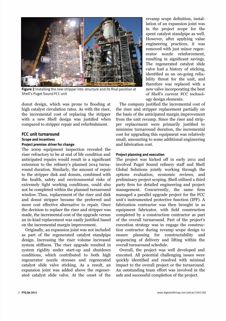
Figure 2 Installing the new stripper into structure and its final position atShell’s Puget Sound FCC unit
7/23/2019 FCC Profitability Assessment via Advanced Modeling
http://slidepdf.com/reader/full/fcc-profitability-assessment-via-advanced-modeling 3/10
Puget Sound FCC unit todayToday, Puget Sound’s FCC unit operates on aver-age at rates up to 52000 b/d, processing
vacuum gasoil and unhydrotreated heavy coker
gasoil. The unit includes Shell’s technology
designs installed during the latest revamp in
March and April of 2014. The present
unit conguration following the revamp includes
the following plant upgrades (see Figure 2):
• New riser of larger diameter, new HIB rings to
inner lining and increased residence time
• New J-Bend
• New feed nozzles including associated piping• New stripper, lengthened and upgraded from
disk and donuts to Shell’s PentaFlow bafe design
• New regenerated catalyst slide valve incorpo-
rating current best practice design
• Regenerator standpipe expansion bellows to
alleviate stresses
• Upgraded IPF system with new instrumenta-
tion and logic system
• Completion of new DCS cutovers.
The revamp was successfully completed on
time, within the turnaround window and theplanned budget. Post turnaround, the unit has
operated very well, realising an estimated benet
matching the expected cost versus forecasted
gains as the business basis for the revamp.
New hardware installedShell has led active research in FCC technology
development for over seven decades since its rst
FCC unit start-up in 1942. As an operator, the
company has safely and successfully operated
www.digitalrefining.com/article/1001180 PTQ Q4 2015 3
FCC units for over 1200 unit-years, and has
designed 33 grassroots FCC units. Since 2006,Shell Global Solutions has successfully completed
over 40 FCC unit revamps across Shell owned, JV
operated and third party licensed reneries. The
portfolio of Shell’s FCC technologies that have
been implemented in these revamp projects
include: reactor and regenerator vessels with
internals; feed injection nozzles; close-coupled
reactor and regenerator cyclones; catalyst circula-
tion enhancement technology (CCET); catalyst
stripper PentaFlow bafes; air grid and spent
catalyst distributor (SCID); and third stageseparators (TSS). Most of these FCC equipment
specic technologies were incorporated in a major
riser replacement revamp project in 2012 at
Shell’s Deer Park renery.1,2 Among the technolo-
gies listed above, some were already present in
Puget Sound renery’s FCC unit prior to the turn-
around (for instance, reactor and regenerator
cyclone technology and air grid). Most of the
remaining technologies were incorporated during
the 2014 riser and stripper revamp project
described in this article.
Riser Internals
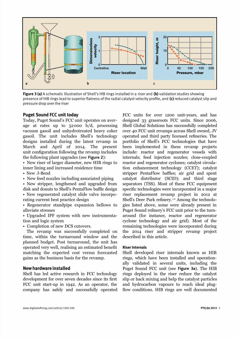
Shell developed riser internals known as HIB
rings, which have been installed and operation-
ally validated in several units, including the
Puget Sound FCC unit (see Figure 3a). The HIB
rings deployed in the riser reduce the catalyst
slip or back mixing and help the catalyst particles
and hydrocarbon vapours to reach ideal plug-
ow conditions. HIB rings are well documented
20
10
R i s e r h e i g h t , m
0
0 50 100 150 2 00
Pressure, mbar
2
1
D i m
e n s i o n l e s s
v e l o c i t y
0
Centreline Wall
Riser location
Figure 3 (a) A schematic illustration of Shell’s HIB rings installed in a riser and (b) validation studies showingpresence of HIB rings lead to superior flatness of the radial catalyst velocity profile, and (c) reduced catalyst slip andpressure drop over the riser
a b c
7/23/2019 FCC Profitability Assessment via Advanced Modeling
http://slidepdf.com/reader/full/fcc-profitability-assessment-via-advanced-modeling 4/10
for delivering benets such as improved overall
unit performance plus greater exibility to oper-
ate over a wide range of conditions. Independent
benchmarking studies show that HIB rings offer
more uniform catalyst distribution, more even
velocity prole (see Figure 3b), and better catalyst
mixing, which consequently produce lower pres-
sure drop (see Figure 3c) and enhanced product yields when compared to an open riser.3
For the Puget Sound renery FCC revamp,
CFD modelling tools were used to illustrate and
validate the enhanced benets of HIB rings
installed in FCC risers.
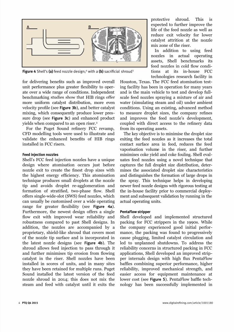
Feed injection nozzles
Shell’s FCC feed injection nozzles have a unique
design where atomisation occurs just before
nozzle exit to create the nest drop sizes with
the highest energy efciency. This atomisationtechnique produces small droplets at the nozzle
tip and avoids droplet re-agglomeration and
formation of stratied, two-phase ow. Shell
offers single-wide-slot (SWS) feed nozzles, which
can usually be customised over a wide operating
range for greater exibility (see Figure 4a).
Furthermore, the newest design offers a single
ow exit with improved wear reliability and
robustness compared to past Shell designs. In
addition, the nozzles are accompanied by a
proprietary, shield-like shroud that covers mostof the nozzle tip surface and is incorporated in
the latest nozzle designs (see Figure 4b). The
shroud allows feed injection to pass through it
and further minimises tip erosion from owing
catalyst in the riser. Shell nozzles have been
installed in scores of units, and in many sites
they have been retained for multiple runs. Puget
Sound installed the latest version of the feed
nozzle shroud in 2014; this does not mix the
steam and feed with catalyst until it exits the
protective shroud. This is
expected to further improve the
life of the feed nozzle as well as
reduce exit velocity for lower
catalyst attrition at the nozzle
mix zone of the riser.
In addition to using feed
nozzles in actual operating
assets, Shell benchmarks its
feed nozzles in cold ow condi-
tions at its in-house FCC
technologies research facility in
Houston, Texas. The FCC feed atomisation test-
ing facility has been in operation for many years
and is the main vehicle to test and develop full-
scale feed nozzles spraying a mixture of air and
water (simulating steam and oil) under ambient
conditions. Using an existing, advanced method
to measure droplet sizes, the company renes
and improves the feed nozzle’s development,coupled with direct access to the renery data
from its operating assets.
The key objective is to minimise the droplet size
exiting the feed nozzles as it increases the total
contact surface area in feed, reduces the feed
vaporisation volume in the riser, and further
minimises coke yield and coke fouling. Shell eval-
uates feed nozzles using a novel technique that
captures the full droplet size distribution, deter-
mines the associated droplet size characteristics
and distinguishes the formation of large drops inthe spray. This technique helps in developing
newer feed nozzle designs with rigorous testing at
the in-house facility prior to commercial deploy-
ment and subsequent validation by running in the
actual operating units.
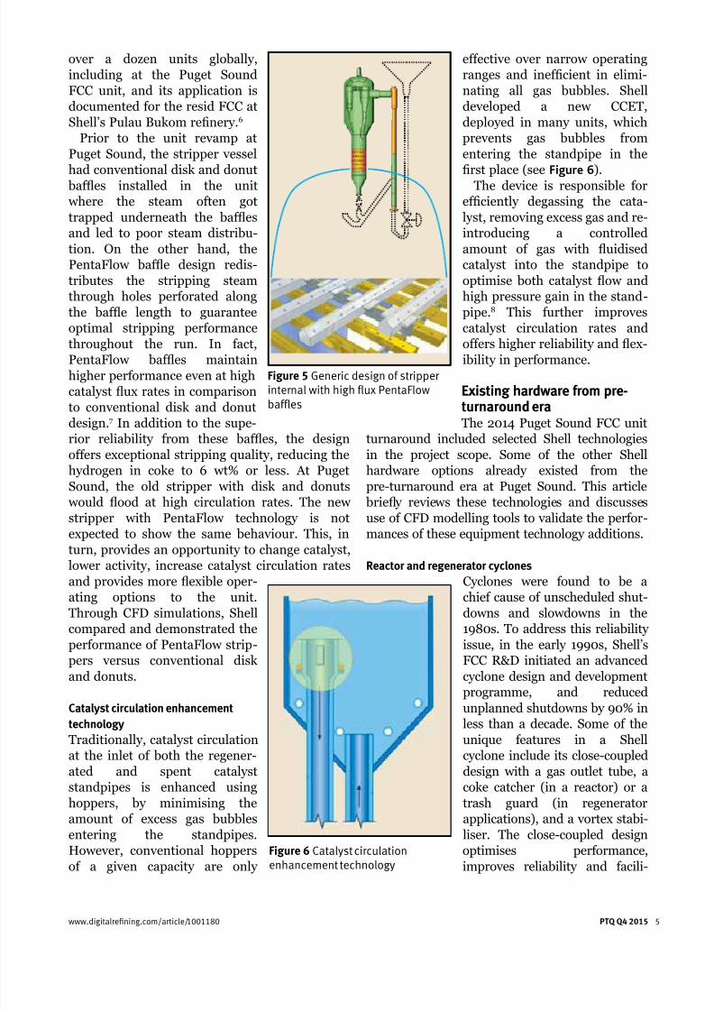
PentaFlow stripper
Shell developed and implemented structured
packing for FCC strippers in the 1990s. While
the company experienced good initial perfor-
mance, the packing was found to progressivelycause plugging, limited catalyst circulation and
led to unplanned shutdowns. To address the
reliability concerns in structured packing in FCC
applications, Shell developed an improved strip-
per internals design with high ux PentaFlow
bafes combining superior performance, higher
reliability, improved mechanical strength, and
easier access for equipment maintenance at
lower cost (see Figure 5). PentaFlow bafe tech-
nology has been successfully implemented in
4 PTQ Q4 2015 www.digitalrefining.com/article/1001180
A B
Figure 4 Shell’s (a) feed nozzle design;4 with a (b) sacrificial shroud5
7/23/2019 FCC Profitability Assessment via Advanced Modeling
http://slidepdf.com/reader/full/fcc-profitability-assessment-via-advanced-modeling 5/10
over a dozen units globally,
including at the Puget Sound
FCC unit, and its application is
documented for the resid FCC at
Shell’s Pulau Bukom renery.6
Prior to the unit revamp at
Puget Sound, the stripper vessel
had conventional disk and donut
bafes installed in the unit
where the steam often got
trapped underneath the bafes
and led to poor steam distribu-
tion. On the other hand, the
PentaFlow bafe design redis-
tributes the stripping steam
through holes perforated along
the bafe length to guarantee
optimal stripping performance
throughout the run. In fact,
PentaFlow bafes maintainhigher performance even at high
catalyst ux rates in comparison
to conventional disk and donut
design.7 In addition to the supe-
rior reliability from these bafes, the design
offers exceptional stripping quality, reducing the
hydrogen in coke to 6 wt% or less. At Puget
Sound, the old stripper with disk and donuts
would ood at high circulation rates. The new
stripper with PentaFlow technology is not
expected to show the same behaviour. This, inturn, provides an opportunity to change catalyst,
lower activity, increase catalyst circulation rates
and provides more exible oper-
ating options to the unit.
Through CFD simulations, Shell
compared and demonstrated the
performance of PentaFlow strip-
pers versus conventional disk
and donuts.
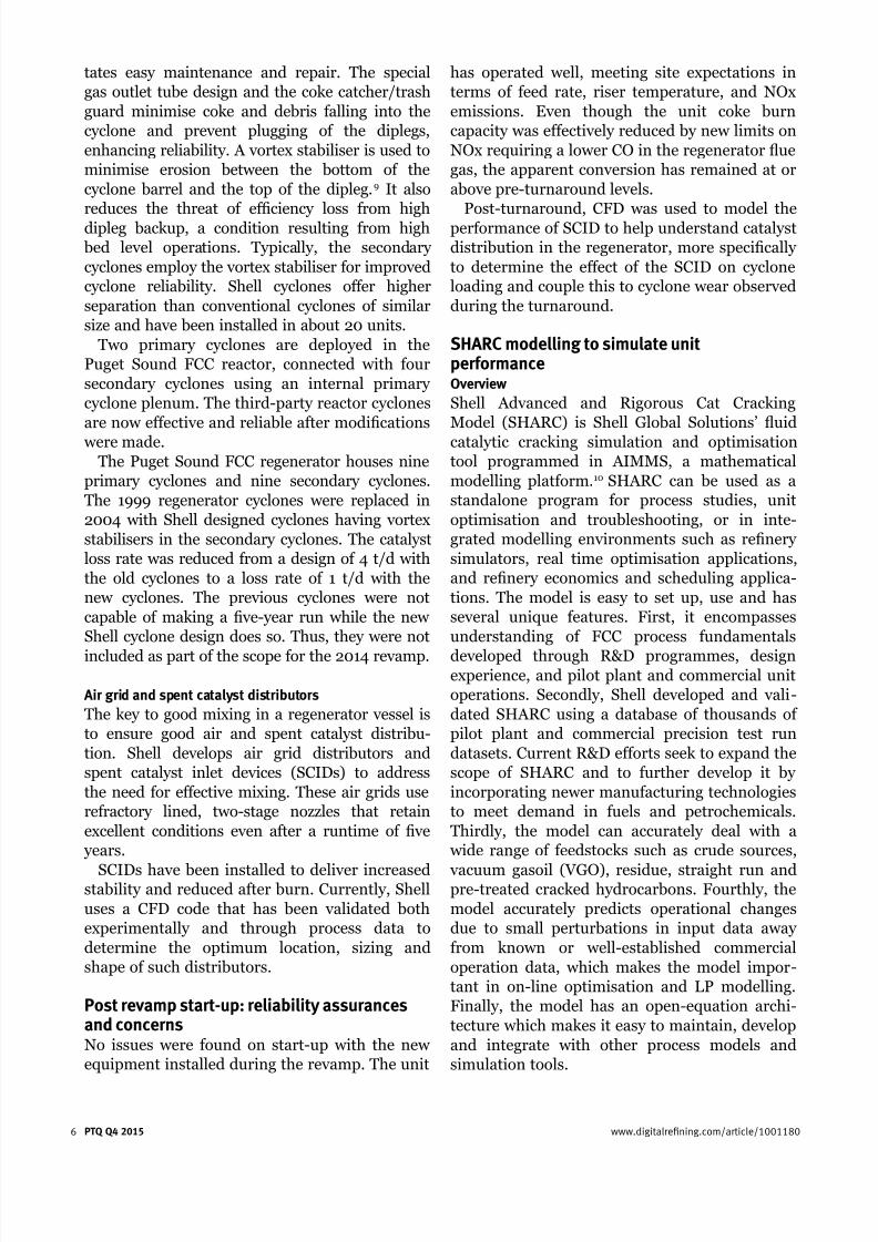
Catalyst circulation enhancementtechnology
Traditionally, catalyst circulation
at the inlet of both the regener-
ated and spent catalyst
standpipes is enhanced using
hoppers, by minimising the
amount of excess gas bubbles
entering the standpipes.
However, conventional hoppers
of a given capacity are only
effective over narrow operating
ranges and inefcient in elimi-
nating all gas bubbles. Shell
developed a new CCET,
deployed in many units, which
prevents gas bubbles from
entering the standpipe in the
rst place (see Figure 6).
The device is responsible for
efciently degassing the cata-
lyst, removing excess gas and re-
introducing a controlled
amount of gas with uidised
catalyst into the standpipe to
optimise both catalyst ow and
high pressure gain in the stand-
pipe.8 This further improves
catalyst circulation rates and
offers higher reliability and ex-
ibility in performance.
Existing hardware from pre-turnaround eraThe 2014 Puget Sound FCC unit
turnaround included selected Shell technologies
in the project scope. Some of the other Shell
hardware options already existed from the
pre-turnaround era at Puget Sound. This article
briey reviews these technologies and discusses
use of CFD modelling tools to validate the perfor-
mances of these equipment technology additions.
Reactor and regenerator cyclones
Cyclones were found to be a
chief cause of unscheduled shut-
downs and slowdowns in the
1980s. To address this reliability
issue, in the early 1990s, Shell’s
FCC R&D initiated an advanced
cyclone design and development
programme, and reduced
unplanned shutdowns by 90% inless than a decade. Some of the
unique features in a Shell
cyclone include its close-coupled
design with a gas outlet tube, a
coke catcher (in a reactor) or a
trash guard (in regenerator
applications), and a vortex stabi-
liser. The close-coupled design
optimises performance,
improves reliability and facili-
www.digitalrefining.com/article/1001180
PTQ Q4 2015 5
Figure 5 Generic design of stripperinternal with high flux PentaFlowbaffles
Figure 6 Catalyst circulationenhancement technology
7/23/2019 FCC Profitability Assessment via Advanced Modeling
http://slidepdf.com/reader/full/fcc-profitability-assessment-via-advanced-modeling 6/10
tates easy maintenance and repair. The special
gas outlet tube design and the coke catcher/trash
guard minimise coke and debris falling into the
cyclone and prevent plugging of the diplegs,
enhancing reliability. A vortex stabiliser is used to
minimise erosion between the bottom of the
cyclone barrel and the top of the dipleg.9 It also
reduces the threat of efciency loss from high
dipleg backup, a condition resulting from high
bed level operations. Typically, the secondary
cyclones employ the vortex stabiliser for improved
cyclone reliability. Shell cyclones offer higher
separation than conventional cyclones of similar
size and have been installed in about 20 units.
Two primary cyclones are deployed in the
Puget Sound FCC reactor, connected with four
secondary cyclones using an internal primary
cyclone plenum. The third-party reactor cyclones
are now effective and reliable after modications
were made.The Puget Sound FCC regenerator houses nine
primary cyclones and nine secondary cyclones.
The 1999 regenerator cyclones were replaced in
2004 with Shell designed cyclones having vortex
stabilisers in the secondary cyclones. The catalyst
loss rate was reduced from a design of 4 t/d with
the old cyclones to a loss rate of 1 t/d with the
new cyclones. The previous cyclones were not
capable of making a ve-year run while the new
Shell cyclone design does so. Thus, they were not
included as part of the scope for the 2014 revamp.
Air grid and spent catalyst distributors
The key to good mixing in a regenerator vessel is
to ensure good air and spent catalyst distribu-
tion. Shell develops air grid distributors and
spent catalyst inlet devices (SCIDs) to address
the need for effective mixing. These air grids use
refractory lined, two-stage nozzles that retain
excellent conditions even after a runtime of ve
years.
SCIDs have been installed to deliver increasedstability and reduced after burn. Currently, Shell
uses a CFD code that has been validated both
experimentally and through process data to
determine the optimum location, sizing and
shape of such distributors.
Post revamp start-up: reliability assurancesand concernsNo issues were found on start-up with the new
equipment installed during the revamp. The unit
has operated well, meeting site expectations in
terms of feed rate, riser temperature, and NOx
emissions. Even though the unit coke burn
capacity was effectively reduced by new limits on
NOx requiring a lower CO in the regenerator ue
gas, the apparent conversion has remained at or
above pre-turnaround levels.
Post-turnaround, CFD was used to model the
performance of SCID to help understand catalyst
distribution in the regenerator, more specically
to determine the effect of the SCID on cyclone
loading and couple this to cyclone wear observed
during the turnaround.
SHARC modelling to simulate unitperformanceOverview
Shell Advanced and Rigorous Cat Cracking
Model (SHARC) is Shell Global Solutions’ uid
catalytic cracking simulation and optimisationtool programmed in AIMMS, a mathematical
modelling platform.10 SHARC can be used as a
standalone program for process studies, unit
optimisation and troubleshooting, or in inte-
grated modelling environments such as renery
simulators, real time optimisation applications,
and renery economics and scheduling applica-
tions. The model is easy to set up, use and has
several unique features. First, it encompasses
understanding of FCC process fundamentals
developed through R&D programmes, designexperience, and pilot plant and commercial unit
operations. Secondly, Shell developed and vali-
dated SHARC using a database of thousands of
pilot plant and commercial precision test run
datasets. Current R&D efforts seek to expand the
scope of SHARC and to further develop it by
incorporating newer manufacturing technologies
to meet demand in fuels and petrochemicals.
Thirdly, the model can accurately deal with a
wide range of feedstocks such as crude sources,
vacuum gasoil (VGO), residue, straight run andpre-treated cracked hydrocarbons. Fourthly, the
model accurately predicts operational changes
due to small perturbations in input data away
from known or well-established commercial
operation data, which makes the model impor-
tant in on-line optimisation and LP modelling.
Finally, the model has an open-equation archi-
tecture which makes it easy to maintain, develop
and integrate with other process models and
simulation tools.
6 PTQ Q4 2015 www.digitalrefining.com/article/1001180
7/23/2019 FCC Profitability Assessment via Advanced Modeling
http://slidepdf.com/reader/full/fcc-profitability-assessment-via-advanced-modeling 7/10
Post-turnaround model tuning
Shell maintains and manages
SHARC models for all the FCC
units it supports. These unit
specic models are referred to
as ‘base cases’. Post-turnaround,
Puget Sound collected test runs
to tune the unit specic SHARC
base case. Upon completion, the
model was updated by Shell
Global Solutions and approved
by the site before being incorpo-
rated into the online optimiser
and LP model. The new base
case (post-turnaround) clearly
characterises the current opera-
tion more closely than the
preceding 2012 base case
(pre-turnaround). SHARC was used for the
Puget Sound FCC unit revamp to evaluate pre-and post-turnaround operation and quantify the
yield shifts and associated margin benets from
the revamp.
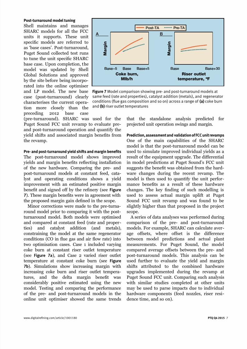
Pre- and post-turnaround yield shifts and margin benefits
The post-turnaround model shows improved
yields and margin benets reecting installation
of the new hardware. Comparing the pre- and
post-turnaround models at constant feed, cata-
lyst and operating conditions shows a yield
improvement with an estimated positive margin benet and signed off by the renery (see Figure
7). These margin benets were in agreement with
the proposed margin gain dened in the scope.
Minor corrections were made to the pre-turna-
round model prior to comparing it with the post-
turnaround model. Both models were optimised
and compared at constant feed (rate and proper-
ties) and catalyst addition (and metals),
constraining the model at the same regenerator
conditions (CO in ue gas and air ow rate) into
two optimisation cases. Case 1 included varyingcoke burn at constant riser outlet temperature
(see Figure 7a), and Case 2 varied riser outlet
temperature at constant coke burn (see Figure
7b). Simulations show increasing margin with
increasing coke burn and riser outlet tempera-
tures, and the delta margin benet was
considerably positive estimated using the new
model. Testing and comparing the performance
of the pre- and post-turnaround models in the
online unit optimiser showed the same trends
that the standalone analysis predicted for
projected unit operation swings and margin.
Prediction, assessment and validation of FCC unit revamps
One of the main capabilities of the SHARC
model is that the post-turnaround model can be
used to simulate improved individual yields as a
result of the equipment upgrade. The differential
in model predictions at Puget Sound’s FCC unit
suggests the benet was obtained from the hard-
ware changes during the recent revamp. The
model is then used to quantify the unit perfor-
mance benets as a result of these hardwarechanges. The key nding of such modelling is
used to assess actual margin uplift at Puget
Sound FCC unit revamp and was found to be
slightly higher than that proposed in the project
scope.
A series of data analyses was performed during
comparison of the pre- and post-turnaround
models. For example, SHARC can calculate aver-
age offsets, where offset is the difference
between model predictions and actual plant
measurements. For Puget Sound, the modelcompared average offsets between the pre- and
post-turnaround models. This analysis can be
used further to evaluate the yield and margin
shifts attributed to the combined hardware
upgrades implemented during the revamp at
Puget Sound FCC unit. Comparing such analysis
with similar studies completed at other units
may be used to parse impacts due to individual
hardware components (feed nozzles, riser resi-
dence time, and so on).
www.digitalrefining.com/article/1001180 PTQ Q4 2015 7
Pre-TA Post-TA
M a r g i n
B
Base Base+30
Riser outlet
temperature, ºF
M a r g i n
A
Base−5 Base+5Base
Coke burn,
Mlb/h
Figure 7 Model comparison showing pre- and post-turnaround models atsame feed (rate and properties), catalyst addition (metals), and regeneratorconditions (flue gas composition and so on) across a range of (a) coke burnand (b) riser outlet temperatures
7/23/2019 FCC Profitability Assessment via Advanced Modeling
http://slidepdf.com/reader/full/fcc-profitability-assessment-via-advanced-modeling 8/10
CFD modelling to showenhanced solid flow in newhardwareComputational uid dynamics
has evolved dramatically since
the development of the rst nite
volume models in the 1980s. It is
only with recent advances in
numerical techniques that
multiphase systems have begun
to be accurately solved on a large
enough scale to be applied in
industry. For example, a typical
FCC unit contains upwards of
1015 particles. The modelling code
of choice at Shell for FCC hybrid
multiphase CFD is the CPFD
Barracuda software package. As
CFD used in this manner is a
relatively new approach, initialstudies focused on applying these
techniques to both experimental
and site problems that can be
validated objectively against
existing data. Given the successes
in recreating operating data,
Shell now uses CFD modelling in
support of hardware design and
scale-up.
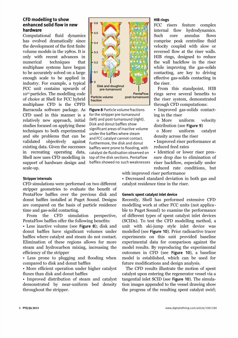
Stripper internalsCFD simulations were performed on two different
stripper geometries to evaluate the benet of
PentaFlow bafes over the previous disk and
donut bafes installed at Puget Sound. Designs
are compared on the basis of particle residence
time and gas-solid contacting.
From the CFD simulation perspective,
PentaFlow bafes offer the following benets:
• Less inactive volume (see Figure 8); disk and
donut bafes have signicant volumes under
bafes where catalyst and steam do not contact.Elimination of these regions allows for more
steam and hydrocarbon mixing, increasing the
efciency of the stripper
• Less prone to plugging and ooding when
compared to disk and donut bafes
• More efcient operation under higher catalyst
uxes than disk and donut bafes
• Improved distribution of steam and catalyst
demonstrated by near-uniform bed density
throughout the stripper.
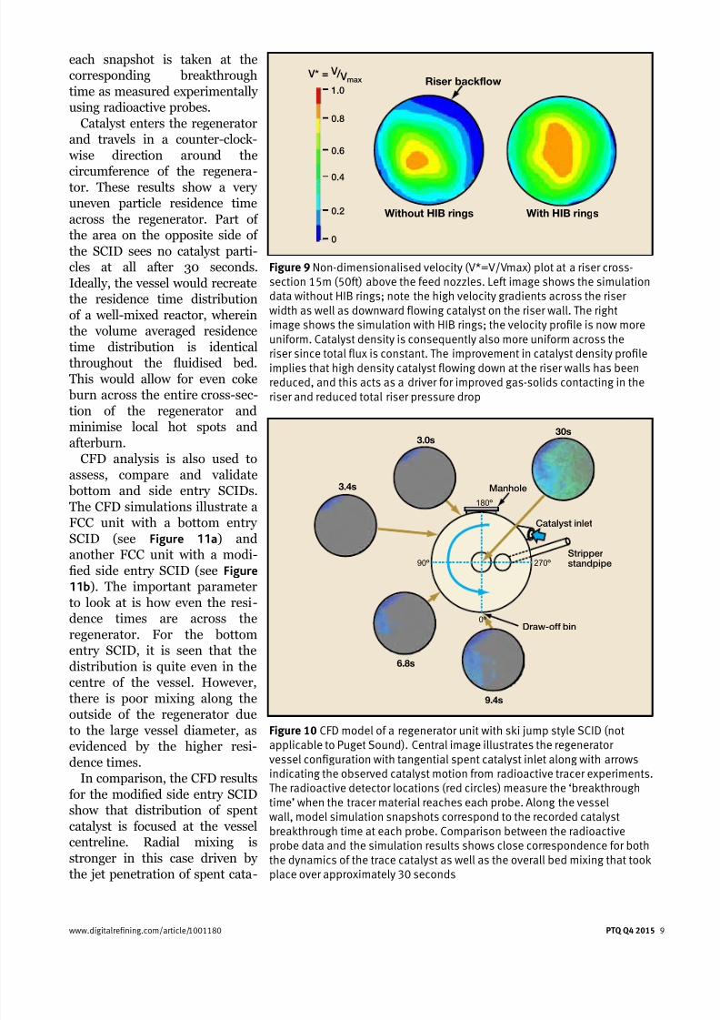
HIB rings
FCC risers feature complex
internal ow hydrodynamics.
Such core annulus ows
comprise peak centreline uid
velocity coupled with slow or
reversed ow at the riser walls.
HIB rings, designed to reduce
the wall backow in the riser
while improving the gas-solids
contacting, are key to driving
effective gas-solids contacting in
the riser.
From this standpoint, HIB
rings serve several benets to
the riser system, demonstrated
through CFD computations:
• Improved gas-solids contact-
ing in the riser
o More uniform velocitydistribution (see Figure 9)
o More uniform catalyst
density across the riser
• Improved riser performance at
reduced feed rates
• Identical or lower riser pres-
sure drop due to elimination of
riser backow, especially under
reduced rate conditions, but
with improved riser performance
• Decreased standard deviation in both gas andcatalyst residence time in the riser.
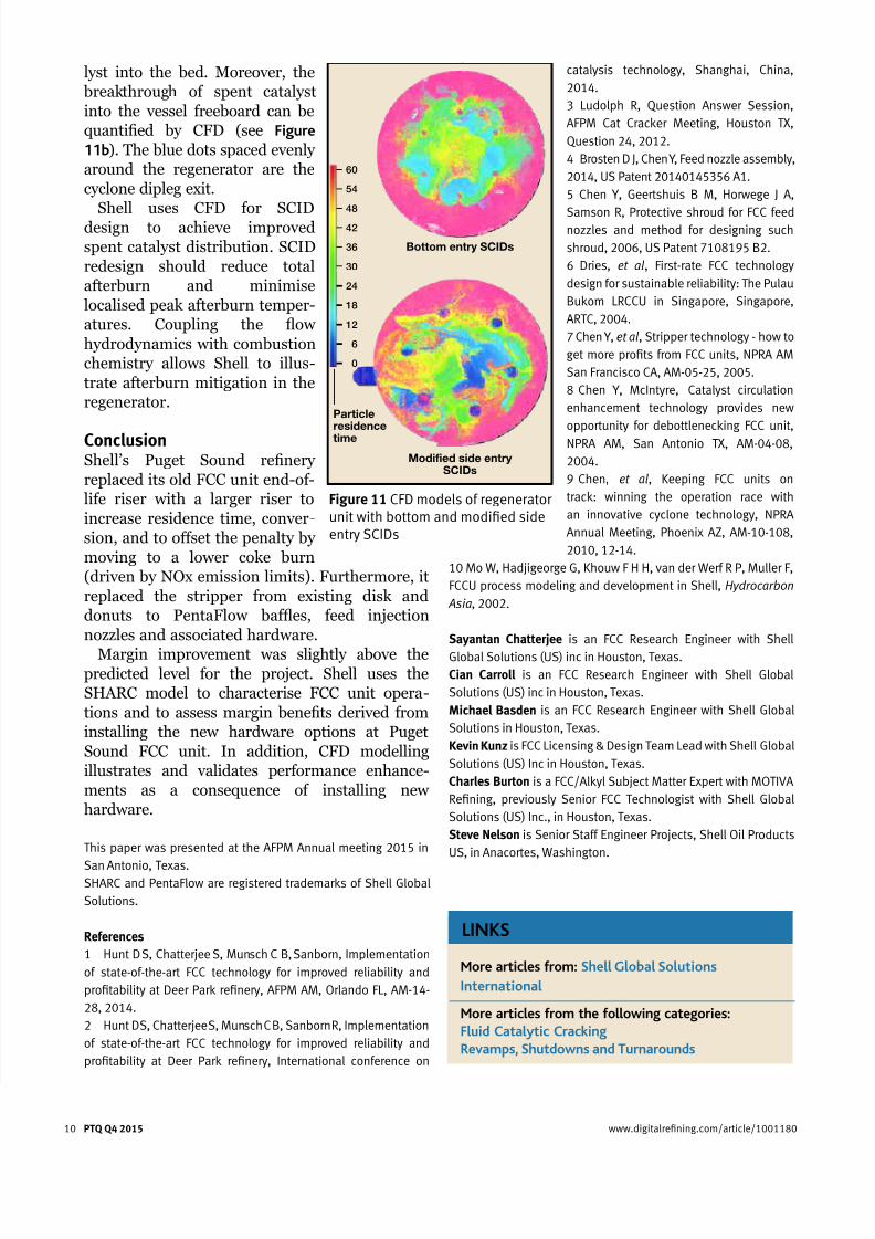
Generic spent catalyst inlet device
Recently, Shell has performed extensive CFD
modelling work at other FCC units (not applica-
ble to Puget Sound) to examine the performance
of different types of spent catalyst inlet devices
(SCIDs). To test the CFD modelling method, a
unit with ski-jump style inlet device was
modelled (see Figure 10). Prior radioactive tracer
experiments on this unit provided baselineexperimental data for comparison against the
model results. By reproducing the experimental
outcomes in CFD (see Figure 10), a baseline
model is established, which can be used for
future modications and design analysis.
The CFD results illustrate the motion of spent
catalyst upon entering the regenerator vessel via a
tangential inlet SCID (see Figure 10). The simula-
tion images appended to the vessel drawing show
the progress of the resulting spent catalyst swirl;
8 PTQ Q4 2015 www.digitalrefining.com/article/1001180
Particle volumefraction
Disk and doughnutpre-turnaround
PentaFlowpost-turnaround
0.6
0.5
0.4
0.3
0.2
0.1
0
Figure 8 Particle volume fractionsfor the stripper pre-turnaround
(left) and post-turnaround (right).Disk and donut baffles showsignificant areas of inactive volumeunder the baffles where steamand FCC catalyst cannot contact.Furthermore, the disk and donutbaffles were prone to flooding, withcatalyst de-fluidisation observed ontop of the disk sections. PentaFlowbaffles showed no such weaknesses
7/23/2019 FCC Profitability Assessment via Advanced Modeling
http://slidepdf.com/reader/full/fcc-profitability-assessment-via-advanced-modeling 9/10
each snapshot is taken at the
corresponding breakthrough
time as measured experimentally
using radioactive probes.
Catalyst enters the regenerator
and travels in a counter-clock-
wise direction around the
circumference of the regenera-
tor. These results show a very
uneven particle residence time
across the regenerator. Part of
the area on the opposite side of
the SCID sees no catalyst parti-
cles at all after 30 seconds.
Ideally, the vessel would recreate
the residence time distribution
of a well-mixed reactor, wherein
the volume averaged residence
time distribution is identical
throughout the uidised bed.This would allow for even coke
burn across the entire cross-sec-
tion of the regenerator and
minimise local hot spots and
afterburn.
CFD analysis is also used to
assess, compare and validate
bottom and side entry SCIDs.
The CFD simulations illustrate a
FCC unit with a bottom entry
SCID (see Figure 11a) andanother FCC unit with a modi-
ed side entry SCID (see Figure
11b). The important parameter
to look at is how even the resi-
dence times are across the
regenerator. For the bottom
entry SCID, it is seen that the
distribution is quite even in the
centre of the vessel. However,
there is poor mixing along the
outside of the regenerator dueto the large vessel diameter, as
evidenced by the higher resi-
dence times.
In comparison, the CFD results
for the modied side entry SCID
show that distribution of spent
catalyst is focused at the vessel
centreline. Radial mixing is
stronger in this case driven by
the jet penetration of spent cata-
www.digitalrefining.com/article/1001180 PTQ Q4 2015 9
Without HIB rings With HIB rings
Riser backflow
0
0.2
0.4
0.6
0.8
1.0
V* = V / V max
Figure 9 Non-dimensionalised velocity (V*=V/Vmax) plot at a riser cross-section 15m (50ft) above the feed nozzles. Left image shows the simulationdata without HIB rings; note the high velocity gradients across the riserwidth as well as downward flowing catalyst on the riser wall. The rightimage shows the simulation with HIB rings; the velocity profile is now moreuniform. Catalyst density is consequently also more uniform across the
riser since total flux is constant. The improvement in catalyst density profileimplies that high density catalyst flowing down at the riser walls has beenreduced, and this acts as a driver for improved gas-solids contacting in theriser and reduced total riser pressure drop
Catalyst inlet
Manhole
Draw-off bin
Stripperstandpipe
0º
180º
270º90º
30s3.0s
3.4s
6.8s
9.4s
Figure 10 CFD model of a regenerator unit with ski jump style SCID (notapplicable to Puget Sound). Central image illustrates the regeneratorvessel configuration with tangential spent catalyst inlet along with arrowsindicating the observed catalyst motion from radioactive tracer experiments.The radioactive detector locations (red circles) measure the ‘breakthroughtime’ when the tracer material reaches each probe. Along the vesselwall, model simulation snapshots correspond to the recorded catalystbreakthrough time at each probe. Comparison between the radioactiveprobe data and the simulation results shows close correspondence for boththe dynamics of the trace catalyst as well as the overall bed mixing that tookplace over approximately 30 seconds
7/23/2019 FCC Profitability Assessment via Advanced Modeling
http://slidepdf.com/reader/full/fcc-profitability-assessment-via-advanced-modeling 10/10
10 PTQ Q4 2015 www.digitalrefining.com/article/1001180
catalysis technology, Shanghai, China,
2014.
3 Ludolph R, Question Answer Session,
AFPM Cat Cracker Meeting, Houston TX,
Question 24, 2012.
4 Brosten D J, Chen Y, Feed nozzle assembly,
2014, US Patent 20140145356 A1.
5 Chen Y, Geertshuis B M, Horwege J A,
Samson R, Protective shroud for FCC feednozzles and method for designing such
shroud, 2006, US Patent 7108195 B2.
6 Dries, et al, First-rate FCC technology
design for sustainable reliability: The Pulau
Bukom LRCCU in Singapore, Singapore,
ARTC, 2004.
7 Chen Y, et al, Stripper technology - how to
get more profits from FCC units, NPRA AM
San Francisco CA, AM-05-25, 2005.
8 Chen Y, McIntyre, Catalyst circulation
enhancement technology provides new
opportunity for debottlenecking FCC unit,
NPRA AM, San Antonio TX, AM-04-08,
2004.
9 Chen, et al, Keeping FCC units on
track: winning the operation race with
an innovative cyclone technology, NPRA
Annual Meeting, Phoenix AZ, AM-10-108,
2010, 12-14.
10 Mo W, Hadjigeorge G, Khouw F H H, van der Werf R P, Muller F,
FCCU process modeling and development in Shell, Hydrocarbon
Asia, 2002.
Sayantan Chatterjee is an FCC Research Engineer with Shell
Global Solutions (US) inc in Houston, Texas.
Cian Carroll is an FCC Research Engineer with Shell Global
Solutions (US) inc in Houston, Texas.
Michael Basden is an FCC Research Engineer with Shell Global
Solutions in Houston, Texas.
Kevin Kunz is FCC Licensing & Design Team Lead with Shell Global
Solutions (US) Inc in Houston, Texas.
Charles Burton is a FCC/Alkyl Subject Matter Expert with MOTIVA
Refining, previously Senior FCC Technologist with Shell Global
Solutions (US) Inc., in Houston, Texas.
Steve Nelson is Senior Staff Engineer Projects, Shell Oil Products
US, in Anacortes, Washington.
lyst into the bed. Moreover, the
breakthrough of spent catalyst
into the vessel freeboard can be
quantied by CFD (see Figure
11b). The blue dots spaced evenly
around the regenerator are the
cyclone dipleg exit.
Shell uses CFD for SCID
design to achieve improved
spent catalyst distribution. SCID
redesign should reduce total
afterburn and minimise
localised peak afterburn temper-
atures. Coupling the ow
hydrodynamics with combustion
chemistry allows Shell to illus-
trate afterburn mitigation in the
regenerator.
ConclusionShell’s Puget Sound renery
replaced its old FCC unit end-of-
life riser with a larger riser to
increase residence time, conver-
sion, and to offset the penalty by
moving to a lower coke burn
(driven by NOx emission limits). Furthermore, it
replaced the stripper from existing disk and
donuts to PentaFlow bafes, feed injection
nozzles and associated hardware.
Margin improvement was slightly above thepredicted level for the project. Shell uses the
SHARC model to characterise FCC unit opera-
tions and to assess margin benets derived from
installing the new hardware options at Puget
Sound FCC unit. In addition, CFD modelling
illustrates and validates performance enhance-
ments as a consequence of installing new
hardware.
This paper was presented at the AFPM Annual meeting 2015 in
San Antonio, Texas.SHARC and PentaFlow are registered trademarks of Shell Global
Solutions.
References
1 Hunt D S, Chatterjee S, Munsch C B, Sanborn, Implementation
of state-of-the-art FCC technology for improved reliability and
profitability at Deer Park refinery, AFPM AM, Orlando FL, AM-14-
28, 2014.
2 Hunt D S, Chatterjee S, Munsch C B, Sanborn R, Implementation
of state-of-the-art FCC technology for improved reliability and
profitability at Deer Park refinery, International conference on
Bottom entry SCIDs
Modified side entrySCIDs
Particleresidence
time
60
54
48
42
36
30
24
18
12
6
0
Figure 11 CFD models of regeneratorunit with bottom and modified sideentry SCIDs
LINKS
More articles from: Shell Global Solutions
International
More articles from the following categories:
Fluid Catalytic Cracking
Revamps, Shutdowns and Turnarounds