Embed Size (px)
Citation preview

FCC Spent Catalyst Stripper Technology
Paul D. WendtFCC Technology Manager
CB&I
Coking and CatCracking Conference
New Delhi, October 2013

Spent Catalyst Stripper Technology
• Big Picture Overview• Process Considerations• Development History• Key Design Considerations• ModGrid™ Stripper Internals Features• Assessing Performance• Commercial Examples

• Critical component of the FCC reaction system• Designed to recover hydrocarbon vapors entrained with
catalyst via steam stripping– Reduces secondary thermal and catalytic cracking reactions– Reduces coke loading to the regenerator
• Significantly affects profitability of the unit • Easy to operate and monitor• Typically easy to revamp and upgrade
– Relatively low investment cost and quick payouts
• Should always be evaluated when making modifications to any portion of the reactor/regenerator circuit
FCC Spent Catalyst Stripper - The Big Picture
Effect on FCC Performance
• Directly impacts the feed conversion and overall yield selectivity from the unit
• Poor performance can result in:– Downgrade of valuable products– Increased delta-coke or coke on the catalyst– Increased regenerator temperature – Increased dry gas production– Loss of feed processing capacity– Catalyst deactivation
• Directly impacts unit steam usage / sour water production• Key contributor to pressure build upstream of the SCSV• Efficiently removing the hydrocarbon vapors can
significantly improve the unit profitability

• FCC unit performance is dictated by a delicate coke and heat balance
• Heat produced from combustion of coke in regenerator supplies heat to operate the unit
• Four types of coke:– Contaminant coke from feed quality– Catalytic coke from feed conversion– Additive coke from feed metals– Cat-to-oil coke from entraining hydrocarbon leaving the stripper
(interstitial and trapped within pores)
• Contaminant / catalytic / additive coke are functions of feed quality, catalyst type, and reactor temperature
• Cat-to-oil coke largely a function of spent catalyst stripper performance
FCC Process Considerations

FCC Process Considerations
• Understanding coke yield and delta-coke from the heat balance is important for evaluating stripper performance
Coke Yield = (Cat-to-Oil) * (Delta-Coke)
Delta-Coke = (CSC – CRC) α (TReg – TRxt)
• Coke yield is essentially set by operating conditions– Riser outlet temperature, feed preheat temperature, etc.
• Delta-coke improvements required to increase cat-to-oil• Spent catalyst stripping efficiency directly impacts the
delta-coke

Development History
• Spent catalyst stripper technology has continually evolved over several decades
• Open strippers (no internals)• Disk and donut baffles• Shed deck baffles• Modifications to include holes and tubes in the baffles• Structured packing• Accommodation to annular stripper configurations
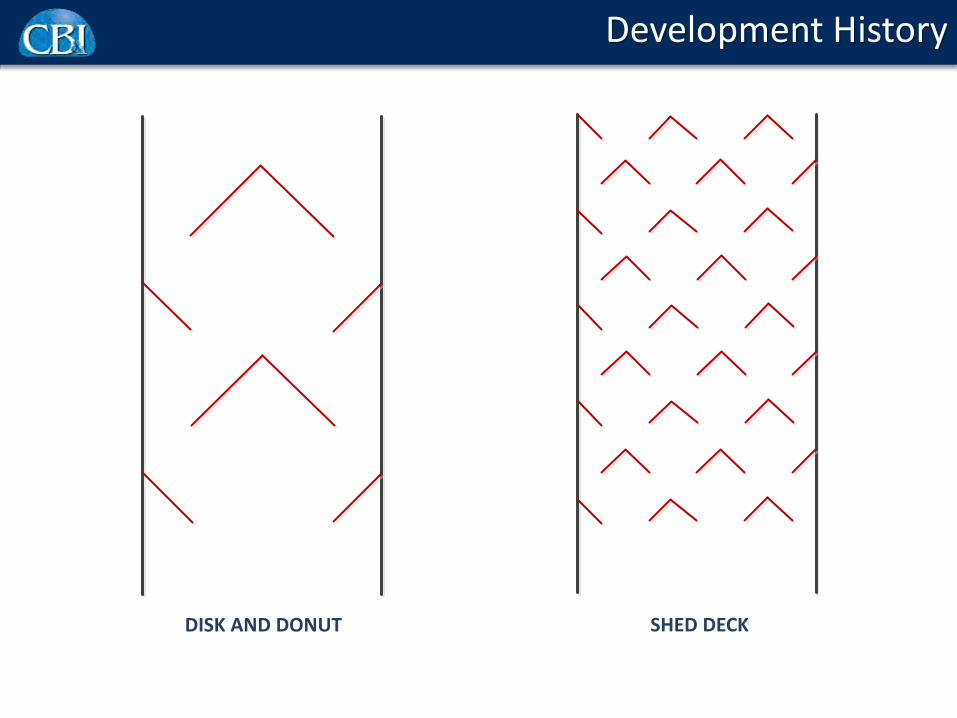
Development History
DISK AND DONUT SHED DECK

Development History
BAFFLED ANNULAR STRIPPER

Stripper Key Design Considerations
• Maximize cross-sectional area of the vessel available for catalyst and steam to flow through it– Utilize the full diameter of the stripper available
• Maximize surface area available for mass transfer per unit volume of the stripper vessel– Enhances mass transfer for efficient stripping and hydrocarbon
recovery
• Provide thorough and uniform contact of the catalyst with the stripping steam– Further enhances mass transfer
• Provide uniform catalyst fluidization– Minimizes stagnant zones that reduce stripping efficiency and
promote coke formation– Minimizes channeling and bypassing

Stripper Key Design Considerations
• Manage the catalyst flux through the stripper– Provides adequate residence time for stripping– Prevents vapor drag into the regenerator
• Optimize the vapor bubble sizes throughout the stripper– Large bubbles rise faster and reduce contacting surface area– Smaller bubbles improve area but can be pulled down
• Maximize pressure build through the stripper– Provides flexibility for increased cat-to-oil– Closely tied to catalyst fluidization
• Optimize location of the stripping steam distributor– Provide ideal steam coverage entering the stripper internals– Minimize steam drag to the regenerator
• Minimize stripping steam requirement– Reduces sour water production and cyclone velocities

Stripper Key Design Considerations
• Provide wide range of operation– Maintain performance from turndown to max throughput
• Ensure catalyst is properly fluidized for entry into spent catalyst standpipe– Proper fluidization exiting the stripper is critical
• Provide structural integrity to handle normal and upset operations– Handle reversals and other severe events
• Provide flexibility to accommodate all unit configurations• Minimize overall weight of the internals• Provide flexibility for ease of fabrication, installation, and
future inspection

Stripper Efficiency Comparison
BafflesLow Catalyst Flux
BafflesMedium Catalyst Flux
BafflesHigh Catalyst Flux
ModGrid™High Catalyst Flux
Good tray operation -most steam flows
upward
Partially flooded trays -significant steam flows
into regenerator
Flooded tray operation -majority of steam flows
into regenerator
Excellent operation -entire stripper volume available for catalyst /
steam contacting

ModGrid™ Catalyst Stripper Internals from CB&I
Baffles angled and oriented such that: – Cross sectional area of stripper vessel available for catalyst
flow is maximized– Surface area available for mass transfer is maximized– Flows of catalyst and steam, and their contact, are uniform– Ideal bubble sizes are produced
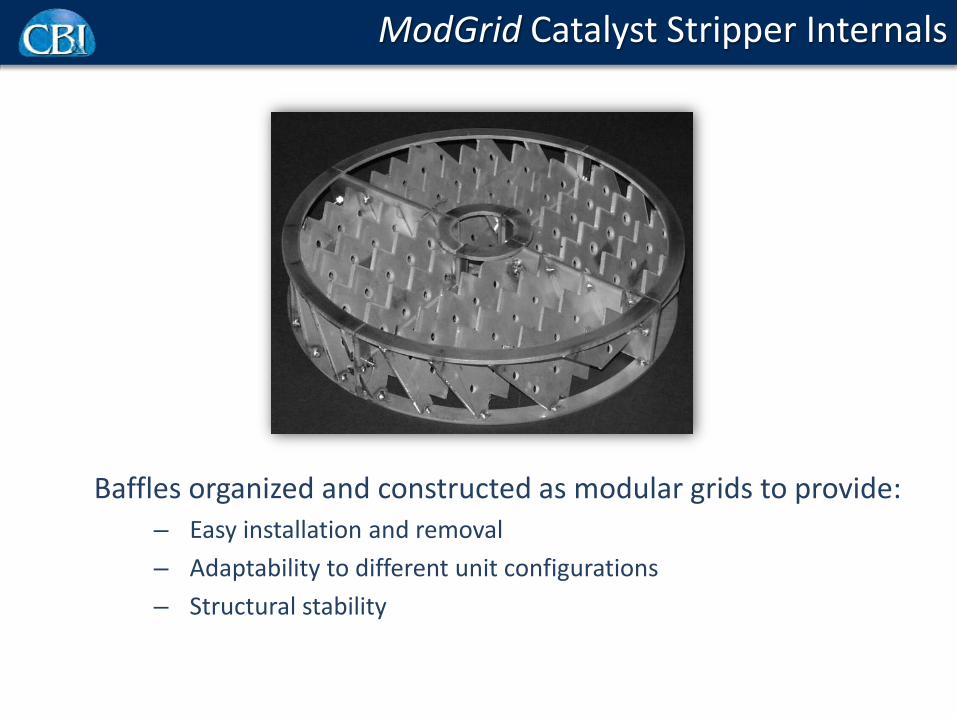
ModGrid Catalyst Stripper Internals
Baffles organized and constructed as modular grids to provide:– Easy installation and removal– Adaptability to different unit configurations– Structural stability

ModGrid Catalyst Stripper Internals
Modular grids are stacked in such a way that catalyst takes 360 deg. turn as it moves down a stack of four grids

ModGrid Catalyst Stripper Benefits
• Reduced delta-coke– Reduced regenerator temperature– Ability to process heavier feed
• Increased cat-to-oil ratio– Higher conversion– Improved liquid yields
• Enhanced recovery of hydrocarbon vapors entrained with the catalyst– Lower dry gas yield– Reduced product downgrade
• Improved pressure build and slide valve pressure differential
• Reduced steam consumption

ModGrid Stripper Cold Flow Model Testing
• Extensive cold flow testing• Disc and donut baffle tested for
comparison• Under all conditions, the ModGrid
design exhibited:– Higher capacity– Higher efficiency– Efficiency nearly constant over wide
range in catalyst fluxStripper Gas
Riser Gas
Stripper Section
ButterflyValve
SlideValve
~40 ft

ModGrid Cold Flow Model Snapshot

ModGrid Stripper Efficiency Comparison
Mass Flux, lb/ft2-sec
Strip
ping
Effi
cien
cy, %
Disk and Donut
ModGrid Stripper

Assessing Performance
• Hydrogen-in-coke has traditionally been used to assess stripper performance– Requires a very reliable flue gas analysis to provide accurate
hydrogen-in-coke values– Calculated number -- difference between two relatively large
numbers– Often leads to scatter in the data analyses– Small changes in flue gas CO2 content can lead to large changes in
the hydrogen-in-coke calculation
• Hydrogen-in-coke can still be used as a secondary indicator of stripper performance
• Typical values range from 6.0 – 9.0– Lowest value possible from ideal stripping is 5.5 – 6.0%
20

Assessing Performance
A CO2 concentration of 16 mol% instead of 15 mol% changes the Hydrogen-in-Coke value by 3 wt%
21

Assessing Performance
• Recommend using primary process variables to assess stripper performance (before and after revamp)– Regenerator dense bed temperature reduction for a given set of
riser outlet and preheat temperatures
• Delta-coke reduction• Combustion air reduction at a given oxygen concentration
in flue gas• Normalization of feedstock properties to negate feed
effects• Match catalyst properties and contaminant levels to
negate catalyst effects• Use cut point corrected product yields for consistency
22

ModGrid Stripper Revamp Results
Refinery A
Pre-revamp Post-revamp
Feed Rate Base +12%Stripping Steam Base -30%Coke, wt% Base -0.5Dry Gas, wt% Base -0.9Gasoline, wt% Base +0.9LCO, wt% Base +1.4

ModGrid Stripper Revamp Results
Refinery B
Pre-revamp Post-revamp
Feed Rate Base +6%Feed Con Carbon, wt% Base +0.4Feed Ni+V, ppmw Base +2.6Feed Iron, ppmw Base +2.1Reactor Temp, F Base +9Regenerator Temp, F Base No change

Thank You!
Paul D. WendtFCC Technology ManagerLummus Refining and Gasification
[email protected]+1-713-375-8358