Embed Size (px)
Citation preview

FDH 3000 864 Termination CabinetWith Universal Splitter Chassis
User Manual
25465-A
www.comscope.com300100103557 Rev B
TECP-96-181 Issue 2, July 2016
Fiber Distribution Hub

TECP-96-181 • Issue 2 • July 2016 • Preface
Page ii
COPYRIGHT
© 2016, CommScope Inc.All Rights Reserved
REVISION HISTORY
TRADEMARK INFORMATION
CommScope, CommScope(logo), and NG4access are registered trademarks of CommScope, Inc.
Telcordia is a registered trademark of Telcordia Technologies, Inc.
GORE is a registered trademark of W. L. Gore & Associates, Inc.
DISCLAIMER OF LIABILITY
Contents herein are current as of the date of publication. CommScope reserves the right to change the contents without prior notice.In no event shall CommScope Inc. be liable for any damages resulting from loss of data, loss of use, or loss of profits andCommScope Inc. further disclaims any and all liability for indirect, incidental, special, consequential or other similardamages. This disclaimer of liability applies to all products, publications and services during and after the warranty period.
This publication may be verified at any time by contacting CommScope’s Technical Assistance Center at 1.800.830.5056, or by e-mail to [email protected].
ISSUE DATE REASON FOR CHANGE
1 6/2014 Original.
2 July 2016 Updated to CommScope format.

ADCP-96-181 • Issue 2 • July 2016 • Preface
TABLE OF CONTENTS
Content Page
TABLE OF CONTENTS
About This Manual . . . . . . . . . . . . . . . . . . . . . . . . . . . . . . . . . . . . . . . . . . . . . . . . . . . . . . . . . . . . . . . . . . . . . . . . . . . v
Related Publications . . . . . . . . . . . . . . . . . . . . . . . . . . . . . . . . . . . . . . . . . . . . . . . . . . . . . . . . . . . . . . . . . . . . . . . . . . v
Admonishments . . . . . . . . . . . . . . . . . . . . . . . . . . . . . . . . . . . . . . . . . . . . . . . . . . . . . . . . . . . . . . . . . . . . . . . . . . . . . v
General Safety Precautions . . . . . . . . . . . . . . . . . . . . . . . . . . . . . . . . . . . . . . . . . . . . . . . . . . . . . . . . . . . . . . . . . . . . . v
Standards Certification . . . . . . . . . . . . . . . . . . . . . . . . . . . . . . . . . . . . . . . . . . . . . . . . . . . . . . . . . . . . . . . . . . . . . . . .vi
List of Acronyms and Abbreviations . . . . . . . . . . . . . . . . . . . . . . . . . . . . . . . . . . . . . . . . . . . . . . . . . . . . . . . . . . . . . . . .vi
1 DESCRIPTION . . . . . . . . . . . . . . . . . . . . . . . . . . . . . . . . . . . . . . . . . . . . . . . . . . . . . . . . . . . . . . . . . . . . . . . . . . 1
1.1 FDH 3000 864 Termination Cabinet . . . . . . . . . . . . . . . . . . . . . . . . . . . . . . . . . . . . . . . . . . . . . . . . . . . . . 1
2 BEFORE STARTING THE INSTALLATION . . . . . . . . . . . . . . . . . . . . . . . . . . . . . . . . . . . . . . . . . . . . . . . . . . . . . . . . 5
2.1 Installation Overview . . . . . . . . . . . . . . . . . . . . . . . . . . . . . . . . . . . . . . . . . . . . . . . . . . . . . . . . . . . . . . . 5
2.2 Unpacking and Inspection. . . . . . . . . . . . . . . . . . . . . . . . . . . . . . . . . . . . . . . . . . . . . . . . . . . . . . . . . . . . 5
2.3 Cabinet Installation Hardware . . . . . . . . . . . . . . . . . . . . . . . . . . . . . . . . . . . . . . . . . . . . . . . . . . . . . . . . . 6
2.4 OSP Cable and Cabinet Grounding Cables. . . . . . . . . . . . . . . . . . . . . . . . . . . . . . . . . . . . . . . . . . . . . . . . . 6
2.5 Tools and Materials Required for Installation . . . . . . . . . . . . . . . . . . . . . . . . . . . . . . . . . . . . . . . . . . . . . . 6
2.6 Cabinet Mounting . . . . . . . . . . . . . . . . . . . . . . . . . . . . . . . . . . . . . . . . . . . . . . . . . . . . . . . . . . . . . . . . . 7
3 MOUNTING THE CABINET ON A MOUNTING SLEEVE . . . . . . . . . . . . . . . . . . . . . . . . . . . . . . . . . . . . . . . . . . . . . . . . 8
3.1 Installation Recommendations . . . . . . . . . . . . . . . . . . . . . . . . . . . . . . . . . . . . . . . . . . . . . . . . . . . . . . . . 8
3.2 Excavation . . . . . . . . . . . . . . . . . . . . . . . . . . . . . . . . . . . . . . . . . . . . . . . . . . . . . . . . . . . . . . . . . . . . . . 8
3.3 Placement of the FMS . . . . . . . . . . . . . . . . . . . . . . . . . . . . . . . . . . . . . . . . . . . . . . . . . . . . . . . . . . . . . . 9
3.4 Cable Conduit Installation. . . . . . . . . . . . . . . . . . . . . . . . . . . . . . . . . . . . . . . . . . . . . . . . . . . . . . . . . . . 10
3.5 Grounding System Installation. . . . . . . . . . . . . . . . . . . . . . . . . . . . . . . . . . . . . . . . . . . . . . . . . . . . . . . . 10
3.6 Back Fill. . . . . . . . . . . . . . . . . . . . . . . . . . . . . . . . . . . . . . . . . . . . . . . . . . . . . . . . . . . . . . . . . . . . . . . 10
3.7 Mounting the Cabinet on the FMS . . . . . . . . . . . . . . . . . . . . . . . . . . . . . . . . . . . . . . . . . . . . . . . . . . . . . 10
3.8 Grounding Wire Connection To Cabinet. . . . . . . . . . . . . . . . . . . . . . . . . . . . . . . . . . . . . . . . . . . . . . . . . . 13
4 MOUNTING THE CABINET ON A CONCRETE PAD . . . . . . . . . . . . . . . . . . . . . . . . . . . . . . . . . . . . . . . . . . . . . . . . . 15
4.1 Installation Recommendations . . . . . . . . . . . . . . . . . . . . . . . . . . . . . . . . . . . . . . . . . . . . . . . . . . . . . . . 15
4.2 Base Construction and Conduit Installation . . . . . . . . . . . . . . . . . . . . . . . . . . . . . . . . . . . . . . . . . . . . . . . 15
4.3 Concrete Pad Construction . . . . . . . . . . . . . . . . . . . . . . . . . . . . . . . . . . . . . . . . . . . . . . . . . . . . . . . . . . 17
4.4 Grounding System Installation. . . . . . . . . . . . . . . . . . . . . . . . . . . . . . . . . . . . . . . . . . . . . . . . . . . . . . . . 18
4.5 Mounting the Cabinet on the Concrete Pad . . . . . . . . . . . . . . . . . . . . . . . . . . . . . . . . . . . . . . . . . . . . . . . 18
4.6 Grounding Wire Connection To Cabinet. . . . . . . . . . . . . . . . . . . . . . . . . . . . . . . . . . . . . . . . . . . . . . . . . . 21
5 FEEDER AND DISTRIBUTION CABLE CONFIGURATION INFORMATION . . . . . . . . . . . . . . . . . . . . . . . . . . . . . . . . . . . 22
5.1 OSP Feeder Cable Configuration . . . . . . . . . . . . . . . . . . . . . . . . . . . . . . . . . . . . . . . . . . . . . . . . . . . . . . 22
5.2 OSP Distribution Cable Configuration . . . . . . . . . . . . . . . . . . . . . . . . . . . . . . . . . . . . . . . . . . . . . . . . . . . 23
6 PLUG AND PLAY SPLITTER MODULE INSTALLATION . . . . . . . . . . . . . . . . . . . . . . . . . . . . . . . . . . . . . . . . . . . . . . 24
7 DISTRIBUTION PANEL INSTALLATION . . . . . . . . . . . . . . . . . . . . . . . . . . . . . . . . . . . . . . . . . . . . . . . . . . . . . . . . 27
8 ROUTING AND CONNECTING THE SPLITTER OUTPUT FIBERS . . . . . . . . . . . . . . . . . . . . . . . . . . . . . . . . . . . . . . . . 35
8.1 Storing The Splitter Output Fibers . . . . . . . . . . . . . . . . . . . . . . . . . . . . . . . . . . . . . . . . . . . . . . . . . . . . . 35
8.2 Enabling Service To a Subscriber. . . . . . . . . . . . . . . . . . . . . . . . . . . . . . . . . . . . . . . . . . . . . . . . . . . . . . 36
9 PASS-THROUGH ROUTING PROCEDURE. . . . . . . . . . . . . . . . . . . . . . . . . . . . . . . . . . . . . . . . . . . . . . . . . . . . . . . 38
9.1 Splitter Compartment Pass-Through Routing Procedure . . . . . . . . . . . . . . . . . . . . . . . . . . . . . . . . . . . . . . 38
Page iii© 2016, CommScope, Inc.

ADCP-96-181 • Issue 2 • July 2016 • Preface
TABLE OF CONTENTS
Content Page
TABLE OF CONTENTS
9.2 Sliding Adapter Pack Pass-Through Routing Procedure . . . . . . . . . . . . . . . . . . . . . . . . . . . . . . . . . . . . . . 39
10 MAINTENANCE AND REPAIR PROCEDURES . . . . . . . . . . . . . . . . . . . . . . . . . . . . . . . . . . . . . . . . . . . . . . . . . . . . 43
10.1 Painting. . . . . . . . . . . . . . . . . . . . . . . . . . . . . . . . . . . . . . . . . . . . . . . . . . . . . . . . . . . . . . . . . . . . . . . 43
10.2 Distribution Panel Adapter Replacement . . . . . . . . . . . . . . . . . . . . . . . . . . . . . . . . . . . . . . . . . . . . . . . . 43
10.3 Splitter Compartment Adapter Replacement . . . . . . . . . . . . . . . . . . . . . . . . . . . . . . . . . . . . . . . . . . . . . . 44
10.4 Replacing a Damaged Fiber or Connector. . . . . . . . . . . . . . . . . . . . . . . . . . . . . . . . . . . . . . . . . . . . . . . . 45
10.4.1 Splitter Output Fiber Connector Replacement . . . . . . . . . . . . . . . . . . . . . . . . . . . . . . . . . . . . . . 46
10.5 Door Gasket Replacement . . . . . . . . . . . . . . . . . . . . . . . . . . . . . . . . . . . . . . . . . . . . . . . . . . . . . . . . . . 46
10.6 Door Replacement . . . . . . . . . . . . . . . . . . . . . . . . . . . . . . . . . . . . . . . . . . . . . . . . . . . . . . . . . . . . . . . 46
10.7 Grounding System Terminal Access Procedure . . . . . . . . . . . . . . . . . . . . . . . . . . . . . . . . . . . . . . . . . . . . 48
11 CUSTOMER INFORMATION AND ASSISTANCE. . . . . . . . . . . . . . . . . . . . . . . . . . . . . . . . . . . . . . . . . . . . . . . . . . . 50
_________________________________________________________________________________________________________
Page iv© 2016, CommScope, Inc.

ADCP-96-181 • Issue 2 • July 2016 • Preface
ABOUT THIS MANUAL
This publication describes the OmniReach 864 termination FDH 3000 cabinet withuniversal splitter chassis. Also included are procedures for mounting the cabinet,installing additional splitter modules, installing additional distribution panels, storing thesplitter output fibers, connecting the splitter output fibers to the distribution fibers, andreplacing damaged components.
RELATED PUBLICATIONS
Listed below are related manuals and their publication numbers. Copies of thesepublications can be ordered by contacting the CommScope Technical AssistanceCenter at 1.800.830.5056, or by e-mail to [email protected].
Optical Fiber Connector Wet and Dry Cleaning Instructions ADCP-90-159
ADMONISHMENTS
Important safety admonishments are used throughout this manual to warn of possiblehazards to persons or equipment. An admonishment identifies a possible hazard andthen explains what may happen if the hazard is not avoided. The admonishments — inthe form of Dangers, Warnings, and Cautions — must be followed at all times. Thesewarnings are flagged by use of the triangular alert icon (seen below) and are listed indescending order of severity of injury or damage and likelihood of occurrence.
GENERAL SAFETY PRECAUTIONS
Title/Description Publication Number
Danger: Danger is used to indicate the presence of a hazard that will cause severe personalinjury, death, or substantial property damage if the hazard is not avoided.
Warning: Warning is used to indicate the presence of a hazard that can cause severe personalinjury, death, or substantial property damage if the hazard is not avoided.
Caution: Caution is used to indicate the presence of a hazard that will or can cause minorpersonal injury or property damage if the hazard is not avoided.
Warning: Wet conditions increase the potential for receiving an electrical shock wheninstalling or using electrically-powered equipment. To prevent electrical shock, never install oruse electrical equipment in a wet location or during a lightning storm.
Page v© 2016, CommScope, Inc.
ADCP-96-181 • Issue 2 • July 2016 • Preface
STANDARDS CERTIFICATION
Telcordia: This equipment complies with the applicable sections of GR-2898-CORE(Issue 2, December 1999)
LIST OF ACRONYMS AND ABBREVIATIONS
The acronyms and abbreviations used in this manual are detailed in the following list:
AWG American Wire GaugeC CentigradeF Fahrenheit
FDH Fiber Distribution HubFMS polymer concrete Mounting Sleeve
FTTP Fiber To The PremisesOSP Outside PlantPMF Pad Mount FramePNP Plug and Play
Danger: Do not look into the ends of any optical fiber. Exposure to laser radiation may result.Do not assume the laser power is turned-off or that the fiber is disconnected at the other end.
Danger: Use adequate lifting equipment when moving or installing Fiber Distribution Hubcabinets. Verify that the maximum lift weight rating of the equipment is sufficient to handle theweight of the cabinet.
Danger: Do not stand under a Fiber Distribution Hub cabinet as it is being hoisted intoposition for mounting. A failure of the lifting equipment or apparatus could result in seriouspersonal injury and cause significant damage to the cabinet.
Warning: Before digging, check with all local utilities for the presence of buried cables orpipes. Contact with underground cables or pipes, especially electric power cables and gasservice lines, could interrupt local utility service and cause serious personal injury andextensive property damage.
Page vi© 2016, CommScope, Inc.

ADCP-96-181 • Issue 2 • July 2016
1 DESCRIPTION
This section provides a description of the OmniReach 864 termination FDH 3000cabinet with universal splitter chassis. This section also gives the cabinetspecifications.
1.1 FDH 3000 864 Termination Cabinet
The 864 termination FDH 3000 cabinet with universal splitter chassis is a secure,above-ground, outdoor fiber optic distribution cabinet that is designed to serve as asignal distribution point in Fiber To The Premises (FTTP) optical networks. The cabinetfeatures optical splitters that allow input signals to be split into multiple connectorizedoutputs. The splitter function minimizes the number of field splices that have to beperformed when customers are added. Customers can be added in switchboardfashion by simply repositioning connectors. The 864 termination cabinet is designed forpedestal-mount applications only. A typical cabinet is shown in Figure 1.
The interior of the FDH 3000 864 termination cabinet consists of the following primarycomponents:
Distribution Panels: Provide a point for connecting the splitter output fibers with theterminated distribution cable fibers. Each panel provides mounting spaces for 72bulkhead adapters. The cabinet may be equipped with up to twelve distribution panels.Adapters for UPC/SC or APC/SC style connectors are available.
Storage Panels: Provide a temporary “parking lot” for unused splitter output fibers.Each splitter module comes with a connector pack that mounts in the storage panel. Upto thirty-six 8-position connector packs (288 fibers total) can be mounted in the storagepanels.
Radius Limiters: Provide a place for storing excess slack from the splitter outputfibers.
Splitter Compartments: Provide a place for mounting the splitters. Will support up toforty-eight splitters. Unused splitter slots can be used for pass-though fibers. Thesplitters specified for use with the FDH 3000 cabinet are equipped with bend-optimizedfibers.
Sliding Adapter Packs (Input panel) – Provide a place for terminating the feeder cablefibers when splitter modules with connectorized input fibers are used with the cabinet.Provide a place for terminating spare feeder cable fibers when “plug and play” (PNP)splitter modules are used with the cabinet. Spare feeder cable fibers are typically usedfor signal pass-through functions.
Grounding System – Provides a point for grounding the cabinet and OSP cables.
The exterior shell of the FDH 3000 cabinet is constructed of heavy gauge aluminumand is coated with an almond-colored finish. Each cabinet is equipped with two frontand two rear doors that provide full front access to the optical components. The cabinetdoors are equipped with a tamper-resistant latch that includes a hasp for a padlock,stainless steel hinges, and door catches that prevent accidental closing. Access to thecabinet requires a 216B key tool (accessory) to release the latch handle. Lifting eyes
Page 1© 2016, CommScope, Inc.

ADCP-96-181 • Issue 2 • July 2016
are provided for hoisting the cabinet into position for mounting. Each cabinet isequipped with two 6-inch risers to provide additional ground clearance.
The cabinet is equipped with a left and right swing frame. Each swing frame rotatesoutward from the front of the cabinet. This provides complete access to most of thecomponents mounted with the cabinet.
Page 2© 2016, CommScope, Inc.

ADCP-96-181 • Issue 2 • July 2016
Figure 1. FDH 3000 864 Termination Cabinet
25466-C
FRONT
DISTRIBUTIONPANELS 7 - 12
DISTRIBUTIONPANELS 1 - 6
STORAGEPANELS
STORAGEPANELS
SPLITTERCOMPARTMENT
(1 - 24)
SPLITTERCOMPARTMENT
(25 - 48)
RADIUSLIMITERS
SLIDINGADAPTER PACK
SLIDINGADAPTER PACK
NOTE: THE CABINET IS EQUIPPED WITH A LEFT AND RIGHT SWING FRAME. EACH SWING FRAME ROTATES OUTWARDTOWARD THE FRONT OF THE CABINET. THIS PROVIDES ACCESS TO MOST OF THE COMPONENTS WITHIN THE CABINET.
BACK
RADIUSLIMITERS
Page 3© 2016, CommScope, Inc.

ADCP-96-181 • Issue 2 • July 2016
The cabinet may be mounted on a concrete pad or on a polymer concrete mountingsleeve. Mounting kits (accessories) are available for each mounting option. The feederand distribution cables enter/exit the cabinet from the bottom. Clamps secure thecables to the inside of the cabinet. The bottom of the cabinet is enclosed with amoisture barrier. The cable entry/exit hole is fitted with a flexible membrane to resistthe entry of dust and moisture. GORE membrane vents are provided to release anymoisture that may accumulate within the cabinet.
The cabinet is equipped with factory-installed outside plant (OSP) distribution andfeeder cables. Ribbon and stranded type cables with either dielectric or armoredconstruction are available. The cable stubs are 100, 200, or 350 feet in length. Cableswith metallic shields are fitted with grounding terminals which are connected to thegrounding block with jumper cables. The specifications for the 864 termination FDH3000 cabinet are provided in Table 1.
Table 1. Specifications for 864 Termination FDH 3000 Cabinet With Universal Splitter Chassis
PARAMETER SPECIFICATION
Cabinet
Dimensions (H x W x D) Pedestal-Mount (See Figure 2) 49 x 48 x 20 x inches (124.5 x 121.9 x 50.8 cm)
Weight (fully loaded) 500 lbs (227 kg)
Certification (pending) GR-2898-CORE
Distribution panels (maximum) 12
Distribution ports Up to 864 with twelve 72-port distribution panels
Distribution port adapters/connectors UPC/SC or APC/SC,
Feeder/Distribution cable length 100, 200, or 350 ft.
Splitter compartment splitter capacity 48 splitters
Splitter compartment adapter capacity 48 adapters
Storage panel capacity 288 connectors
Sliding adapter pack capacity 48 adapters
Splitter Modules
Splitter module input and output pig-tails
Bend-optimized fiber terminated with UPC/SC or APC/SC connectors
Test bandpass 1260–1360 nm, 1480–1500 nm, 1550–1560 nm
Overall bandpass 1260–1625 nm
Return loss at test bandpass >55 dB
Maximum insertion loss at test band-pass
Note: Specification includes the loss from the input and output connectors
1 x 161 x 32
13.9 dB with UPC, 14.3 dB with APC17.1 dB with UPC, 17.5 dB with APC
Page 4© 2016, CommScope, Inc.

ADCP-96-181 • Issue 2 • July 2016
Figure 2. Dimensions for 864 Termination FDH 3000 Cabinet With Universal Splitter Chassis
19.58 IN(49.7 CM)
54.88 IN(139.4 CM)
25467-A47.39 IN
(120.4 CM)16.68 IN
(42.37 CM)
42.53 IN(108.0 CM)
Page 5© 2016, CommScope, Inc.

ADCP-96-181 • Issue 2 • July 2016
2 BEFORE STARTING THE INSTALLATION
This section provides general installation considerations, unpacking and inspectionprocedures, and lists the tools and materials required for cabinet installation.
2.1 Installation Overview
Installation of the 864 termination FDH 3000 cabinet involves the following main tasks:
Installing a Support Base (Pedestal-Mount) – The pedestal-mount cabinet must bemounted on a suitable support base. The following two mounting options are available:
• Mounting Sleeve (FMS) – The FMS is a polymer concrete sleeve that mounts inthe ground. The FMS provides a stable mounting platform plus storage spaceunder the cabinet for OSP cable slack. The FMS may also be used as a splicingvault for OSP cables.
• Poured Concrete Pad – Concrete slab with Pad Mounting Frame (PMF). ThePMF is a stainless-steel frame that is embedded in the concrete during installationof the slab. The cabinet attaches to the PMF which holds it securely to the slab.
Mounting the Cabinet – After the support base is installed, the cabinet must besecured to the support base. The OSP feeder and distribution cables must be uncoiledand routed to a separate splice enclosure (not provided) before the cabinet is securedto the support base.
Splitter Installation – The cabinet may be ordered with one or two splitters. Ifadditional splitters are required, they must be ordered separately. All splitter modulesthat are ordered separately must be installed in the splitter compartment and the inputconnectors must be mated with the terminated feeder cable fibers.
Splitter Output Fiber Connections – Service is enabled by connecting the splitteroutput fiber connectors to the subscriber distribution ports. Unused output fibers aretemporarily “parked” in the storage panel until they are needed for service.
2.2 Unpacking and Inspection
This section provides instructions for opening the shipping boxes, verifying that allparts have been received, and verifying that no shipping damage has occurred.
Use the following procedure to unpack and inspect the cabinet and all accessories:
1. Open the shipping carton(s) and carefully unpack the cabinet and any accessoriesfrom the protective packing material.
2. Open the cabinet doors (requires 216B key tool) and check for broken or missingparts. If there are damages, contact TE.
Page 6© 2016, CommScope, Inc.

ADCP-96-181 • Issue 2 • July 2016
2.3 Cabinet Installation Hardware
The cabinet is shipped with various parts (see Table 2) that are used for securing thecabinet to the FMS or PMF. Verify that the parts specified are received.
2.4 OSP Cable and Cabinet Grounding Cables
The cabinet is equipped with a common grounding block that is used to tie together allthe components of the cabinet that must be grounded. The cabinet itself and any OSPcables with metallic strength members must be connected to an earth ground source.Information on grounding is provided in the sections that cover cabinet mounting.
2.5 Tools and Materials Required for Installation
The following tools and materials are required for cabinet installation:
All Cabinet Installations
• Hammer
• Wire cutter
• Utility knife
• Screwdriver (flat blade)
• 9/16-inch wrench
• Torque wrench (with 7/16-inch socket and standard screwdriver socket)
• Tape measure
• Pen or marker
• 216B key tool (accessory - required to open cabinet door)
• 3/16-inch hex-key (required to open riser security panel)
• 7/32-inch hex-key (required to remove lifting eyes)
• Padlock (optional)
Table 2. Cabinet Installation Hardware
ITEM QUANTITY
3/8 x 1-inch hex head capscrews 8
3/8-inch flat washers 8
3/8-inch lock washers 8
Isolation gasket 1
Page 7© 2016, CommScope, Inc.

ADCP-96-181 • Issue 2 • July 2016
• Grounding system, copper wire, and grounding clamp (per local requirements)
• Splicing equipment for splicing OSP feeder and distribution cables
• Lifting equipment for hoisting the cabinet into position for mounting
• Level
• Excavation and earth moving equipment
• Landscaping equipment and site restoration supplies
Mounting Sleeve Installation
• Mounting Sleeve kit (FMS-FD3J-KIT-A)
• Stone aggregate
• Tamping equipment
• Hole saw and drill (use to cut holes for cable conduit if pre-drilled holes are not usable)
Concrete Pad Installation
• Pad Mount Frame kit for 864 termination FDH 3000 cabinet (FD3-PMFJ06)• Concrete finishing equipment• Approximately 11.5 cu. ft. concrete • Sand or gravel• Tamping equipment• 2 x 6 inch framing lumber• 1 x 4 inch wooden stakes (4)• Nails and construction screws• Utility wire (to secure PMF during installation)• Saw• Drill with screwdriver bits• Square
2.6 Cabinet Mounting
The next two sections provide installation instructions for the various cabinet mountingsystems. Use whichever procedure is appropriate for the installation.
Page 8© 2016, CommScope, Inc.

ADCP-96-181 • Issue 2 • July 2016
3 MOUNTING THE CABINET ON A MOUNTING SLEEVE
The FMS, shown in Figure 3, is a polymer concrete sleeve that may be used to supportthe cabinet at ground level. The FMS may also be used as a splicing vault. Fourvertical racks are molded into the sides of the FMS to accommodate removable rungs(not provided). The rungs provide support for splice cases or OSP cable storage.
3.1 Installation Recommendations
The site chosen for the installation must conform to all local codes and any permitsrequired must be obtained prior to the start of installation. The location must beaccessible and provide adequate parking for worker and vehicle safety. Situate theFMS close to the trench that was used for routing the OSP fiber cables for the networkdistribution system.
The installed cabinet must not create a visual or physical obstruction to vehicular orpedestrian traffic. Ensure that there is sufficient space on all sides to facilitate cabinetinstallation. Depending on the landscaping requirements, the top surface of themounting sleeve may be located from 0 to 4 inches (10.2 cm) above the surroundinggrade.
Figure 3. Mounting Sleeve (FMS-FD3J-KIT-A)
3.2 Excavation
The excavation must be large enough to provide a fill base that will maintain stability forthe FMS and the cabinet mounted on it. There must be room for 12 inches (30.5 cm) of
FMSSLEEVECOVER
21618-B
50.75 IN.(128.9 CM)
34.0 IN.(86.4 CM)
54.0 IN.(137.2 CM)
66.0 IN.(167.6 CM)
MOUNTINGSLEEVE (FMS)
31.38 IN.(79.7 CM)
FMSADAPTER
PLATE
Page 9© 2016, CommScope, Inc.

ADCP-96-181 • Issue 2 • July 2016
fill below and on each side of the FMS. The excavation dimensions for the FMS areshown in Figure 4. Excavate a rectangular hole for the FMS.
Figure 4. Excavation Recommendations for FMS-ACE300-KIT-A
3.3 Placement of the FMS
Use the following procedures to place the FMS into the excavation.
1. Fill the bottom of the hole with stone aggregate, tamping it as it is filled to build a 12inch (30.5 cm) layer with a level surface. The stone aggregate will provide a stablebase to support the FMS.
Danger: Use adequate lifting equipment when installing the FMS. Do not stand in the hole whileplacing the FMS in position. An unexpected shift of the FMS could result in personal injury.
21520-B
90 IN. (229 CM)
78 IN. (198 CM)
49.25 IN(125 CM)
12 IN(30.5 CM)
12 IN(30.5 CM)
CONDUITENTRANCE
HOLES
COMPACTED SOIL
COMPACTED SOIL
TAMP AGGREGATE ASHOLE IS FILLED
GRADE
TOPSOIL ORDECORATIVE ROCK
CONDUITENTRANCE
HOLES
VERTICAL RACKSFOR MANHOLE
CABLE SUPPORT BARS
SIDEVIEW
ENDVIEW
STONEAGGREGATE FILL
STONEAGGREGATE FILL
Page 10© 2016, CommScope, Inc.

ADCP-96-181 • Issue 2 • July 2016
2. Use appropriate lifting equipment to place the FMS into the center of the hole.Lifting loops are provided on either side of the FMS for attaching a sling or chain.
3. Use a carpenter’s level to verify that the FMS is level. If it is necessary to add orremove fill for leveling, tamp any added fill to maintain the base stability.
3.4 Cable Conduit Installation
Select the conduit entrance holes (see Figure 4) for the OSP feeder and distributioncables. If necessary, additional conduit entrance holes may be cut using a power drilland hole saw. Place and route the conduit into the entrance hole(s). If preferred, theFMS may be installed without conduit. OSP cables may be routed into the FMS at anypoint that is convenient. Cut the cable entrance hole to match the size of the cable.
3.5 Grounding System Installation
Install a grounding system (not provided) that meets all local electrical codes. Checklocal codes for grounding system installation, use of clamps, wire size, and any othergrounding requirements. Typically, #6 AWG copper wire is used for the grounding wire.Install the grounding system inside the FMS where it will not interfere with the conduitor cables. Leave sufficient slack in the grounding wire to allow it to be routed into thecabinet after the cabinet is mounted on the sleeve.
3.6 Back Fill
If installing conduit, hand shovel stone aggregate under the conduit to avoid damagefrom the power tamper. Complete the back fill as follows:
1. Add stone aggregate evenly around the FMS and tamp. Fill to approximately 6inches (15.2 cm) from the top of the excavation.
2. Complete the back-fill with crushed rock or topsoil depending on the landscapingrequirements. The top surface of the mounting sleeve may be located from 0 to 4inches (10.2 cm) above the surrounding grade (see Figure 4).
3.7 Mounting the Cabinet on the FMS
Use the 216B key tool to un-latch and latch the cabinet doors as needed during themounting process. Refer to Figure 5 as necessary when mounting the cabinet.
Note: Use crushed rock 3/8-inch or less in size mixed with stone dust (per localpractice) to fill the hole. The name of the material may differ in differentgeographical areas. Possible names are Class 5, stone dust, aughts (0s) andones (1s), or stone aggregate
Warning: Use appropriate lifting equipment when moving or installing the cabinet. Do notstand under a cabinet as it is being hoisted into position for mounting. A failure of the liftingequipment could result in serious personal injury.
Page 11© 2016, CommScope, Inc.

ADCP-96-181 • Issue 2 • July 2016
Figure 5. Mounting the 864 Termination FDH 3000 Pedestal-Mount Cabinet on the FMS
25469-A
FMS
GROUND SPACER(ACCESSORY)
CAPSCREWS (8),LOCK WASHERS (8),FLAT WASHERS (8)
FEEDER ANDDISTRIBUTION
CABLES
864 TERMINATIONFDH 3000CABINET
(REAR)
ISOLATIONGASKET
FMS SLEEVECOVER
FMS ADAPTERCOVER
GROUNDINGWIRE
CAPSCREWS (8),LOCK WASHERS (8),FLAT WASHERS (8)
Page 12© 2016, CommScope, Inc.
ADCP-96-181 • Issue 2 • July 2016
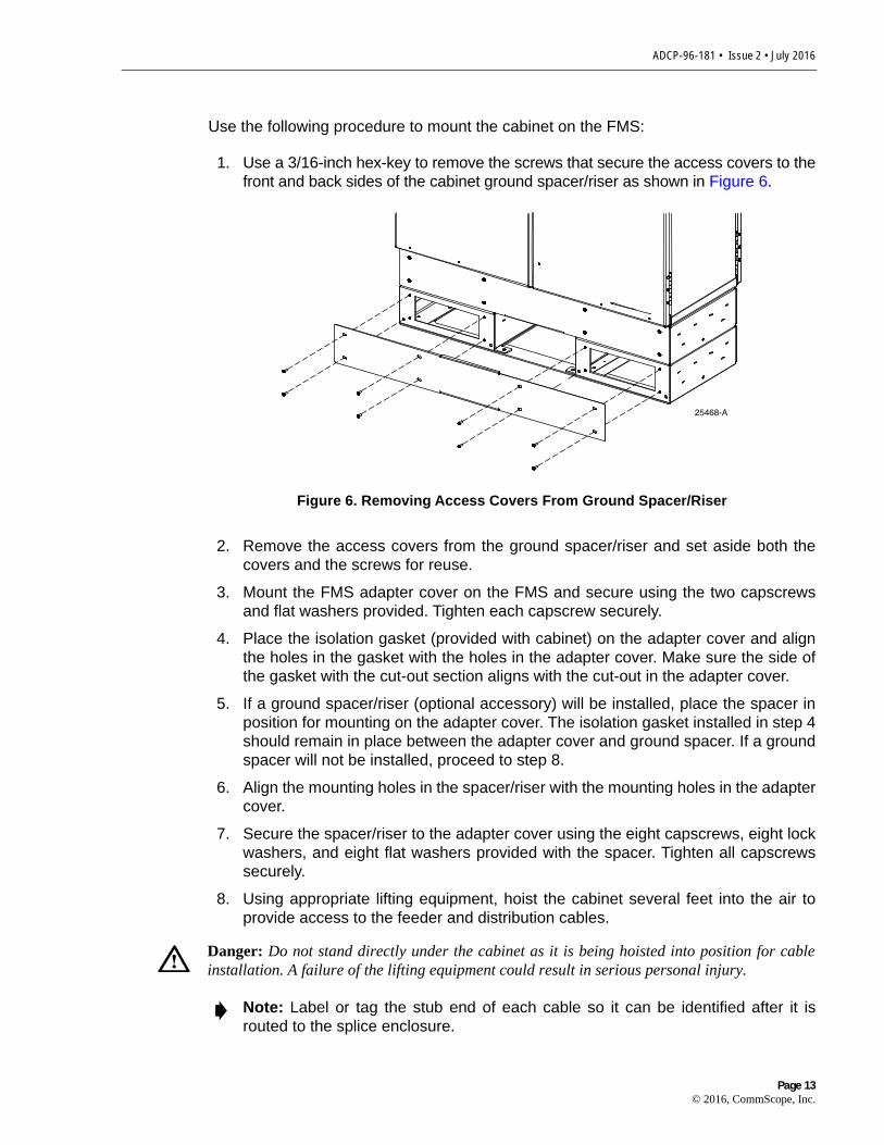
Use the following procedure to mount the cabinet on the FMS:
1. Use a 3/16-inch hex-key to remove the screws that secure the access covers to thefront and back sides of the cabinet ground spacer/riser as shown in Figure 6.
Figure 6. Removing Access Covers From Ground Spacer/Riser
2. Remove the access covers from the ground spacer/riser and set aside both thecovers and the screws for reuse.
3. Mount the FMS adapter cover on the FMS and secure using the two capscrewsand flat washers provided. Tighten each capscrew securely.
4. Place the isolation gasket (provided with cabinet) on the adapter cover and alignthe holes in the gasket with the holes in the adapter cover. Make sure the side ofthe gasket with the cut-out section aligns with the cut-out in the adapter cover.
5. If a ground spacer/riser (optional accessory) will be installed, place the spacer inposition for mounting on the adapter cover. The isolation gasket installed in step 4should remain in place between the adapter cover and ground spacer. If a groundspacer will not be installed, proceed to step 8.
6. Align the mounting holes in the spacer/riser with the mounting holes in the adaptercover.
7. Secure the spacer/riser to the adapter cover using the eight capscrews, eight lockwashers, and eight flat washers provided with the spacer. Tighten all capscrewssecurely.
8. Using appropriate lifting equipment, hoist the cabinet several feet into the air toprovide access to the feeder and distribution cables.
Danger: Do not stand directly under the cabinet as it is being hoisted into position for cableinstallation. A failure of the lifting equipment could result in serious personal injury.
Note: Label or tag the stub end of each cable so it can be identified after it isrouted to the splice enclosure.
25468-A
Page 13© 2016, CommScope, Inc.

ADCP-96-181 • Issue 2 • July 2016
9. Carefully route the stubbed feeder and distribution cables through the rectangularopening in the ground spacer/riser or adapter cover and into the FMS.
10. Feed the stubbed feeder and distribution cables into the appropriate conduitsections and route to the splice enclosure (not provided). Some excess cableslack may be stored in the bottom of the FMS.
11. Lower the cabinet onto the ground spacer/riser or adapter cover and align themounting holes in the cabinet base with the threaded holes in the spacer/riser orcover. If a spacer/riser was not installed, leave the isolation gasket (installed instep 4) in place on the adapter cover.
12. Secure the cabinet to the adapter cover or spacer using the eight capscrews, lockwashers, and flat washers provided with the cover. Tighten all eight capscrewssecurely.
13. Install the FMS cover onto the FMS and secure using the two capscrews andwashers provided. Tighten both capscrews securely.
14. The lifting eyes may be left in place or removed from the cabinet. To remove thelifting eyes, use a 7/32-inch hex-key to remove the lifting eye screws. Store thelifting eyes inside the cabinet and then re-install the lifting eye screws in thecabinet.
15. Reinstall the front and back access covers that were removed in step 1. Use a 3/16-inch hex-key to tighten the screws that secure the access covers to the cabinetground spacer/riser.
3.8 Grounding Wire Connection To Cabinet
Prior to mounting the cabinet, a grounding system and grounding wire should havebeen installed (see Section 3.5) in the space below the cabinet. Use the followingprocedure to connect the grounding wire to the cabinet:
1. Locate the grounding wire that was installed prior to mounting the cabinet on theFMS.
2. Working from the bottom side of the cabinet, insert the grounding wire through theflexible membrane at the point indicated in Figure 7.
3. Route the grounding wire to the cabinet grounding lug located on the right side(viewed from the back) of the cabinet.
4. Attach the grounding wire to the cabinet grounding lug. The grounding lug can beused for #6 – 14 AWG wire.
Note: A separate splice enclosure (not provided) is required for splicing thecabinet OSP cables to the network OSP cables. If required, the splice enclosuremay be mounted within the FMS.
Note: The FMS cover may be installed at a later time to allow the interior of theFMS sleeve to be accessed for cable installation, ground wire installation, orsplicing.
Page 14© 2016, CommScope, Inc.

ADCP-96-181 • Issue 2 • July 2016
5. Tighten the grounding lug set screw to 30 to 35 lbs force – inches (3.4 to 4.0 Nm oftorque).
6. Leave sufficient slack so the grounding wire can be routed and repositioned asneeded.
Figure 7. Grounding Wire Connection To Grounding Bus Bar
4 MOUNTING THE CABINET ON A CONCRETE PAD
The Pad Mount Frame (PMF), shown in Figure 8, is a stainless steel frame thatprovides a mounting base for the cabinet when embedded in a concrete foundation.
GROUNDING WIREENTRY POINT
21639-D
GROUNDING WIRE ROUTEDTO GROUNDING BUS BAR
CABINETGROUNDING LUG
(#6 - #14 AWG WIRE)
Page 15© 2016, CommScope, Inc.

ADCP-96-181 • Issue 2 • July 2016
Figure 8. Pad Mount Frame Dimensions
4.1 Installation Recommendations
The site chosen for the installation must conform to all local codes and any permitsrequired must be obtained prior to the start of installation. The location must beaccessible and provide adequate parking for worker and vehicle safety. Situate theconcrete pad close to the trench that was used for routing the OSP fiber cables for thenetwork distribution system.
The installed cabinet must not create a visual or physical obstruction to vehicular orpedestrian traffic. Ensure that there is sufficient space on all sides to facilitate cabinetinstallation. Depending on the landscaping requirements, the top surface of theconcrete pad may be located from 0 to 3 inches (7.6 cm) above the surrounding grade.
4.2 Base Construction and Conduit Installation
Prepare a base for the concrete pad that meets all local code requirements. The basemust have a footing of 4 to 6 inches (10.2 to 15.2 cm) of sand or gravel (per localpractice) on firmly compacted soil. Refer to the construction diagram in Figure 9 fordetails.
Install the cable conduit from below and position it so that the top of each upward bendwill be located within the PMF opening at the indicated point. When installed, the top ofthe conduit should be located 1 to 2 inches (2.54 to 5.08 cm) below the top of thefinished concrete pad. Install the conduit before pouring the pad.
Caution: Mounting the cabinet directly on a concrete pad may cause chemicalcorrosive action to the cabinet. Use only the Pad Mount Frame (PMF) as a mountingbase for the cabinet. Do not use caulking compounds as a sealer between the cabinetand the PMF.
21711-C
48.88 IN.(124.16 CM) 18.0 IN.
(45.72 CM)
5.5 IN.(14.0 CM)
Page 16© 2016, CommScope, Inc.

ADCP-96-181 • Issue 2 • July 2016
Figure 9. Constructing the Concrete Pad for the 864 Termination FDH 3000 Pedestal-Mount Cabinet
A template is provided with the PMF kit. The template may be used to determine thecable conduit locations. Place the template over the top of the PMF and align cornerholes in the template with the center holes in the PMF as shown in Figure 10. The 4-inch holes punched in the template show the locations for the conduit within the PMF.
64 IN(162.6 CM)
64 IN(162.6 CM)
6 IN. (15.2 CM)
4 IN. MIN.(10.2 CM)
COMPACTED SOIL21712-E
TOP OF PMF SHOULDBE FLUSH WITH TOP
OF CONCRETE
90 BEND IN DUCTS(LOCATE 1-2 INCHESBELOW TOP OF PAD) TOPSOIL OR
DECORATIVE ROCK
GRADE
7.6 IN(19.1 CM)
23 IN(58.4 CM)
3.2 IN(8.1 CM)
26.9 IN(68.4 CM)
REINFORCEDCONCRETE PAD
21.9 IN(55.7 CM)
DO NOT POUR CONCRETE INSIDETHE PAD MOUNT FRAME
PAD MOUNT FRAMECAST IN PLACE
GROUND ROD(LOCATE 1 - 2 INCHESBELOW TOP OF PAD)
SAND OR GRAVEL
CABINET FRONT
7.4 IN(18.9 CM)
BA
4 IN DUCTS FOR LEFT SIDEFEEDER/DISTRIBUTION CABLES
(USE DUCT A FOR LEFT SIDEFACTORY-INSTALLED FEEDER)
4 INCH DUCTS FOR RIGHT SIDEFEEDER/DISTRIBUTION CABLES(USE DUCT B FOR RIGHT SIDE
CUSTOMER-INSTALLED FEEDER)
Page 17© 2016, CommScope, Inc.

ADCP-96-181 • Issue 2 • July 2016
Figure 10. Using the Template To Determine Duct Location Within the PMF
4.3 Concrete Pad Construction
Use the following procedure to construct the concrete pad:
1. Build a wood form for the concrete pad using 2 x 6 framing lumber as shown inFigure 11.
2. Locate the PMF as shown in the construction diagram (see Figure 9). Wheninstalled, the top surface of the PMF must be flush and level with the top of theconcrete pad.
3. Place reinforcing material inside the form but outside of the PMF.
4. Verify that the PMF and form are level. Depending on the landscapingrequirements, the top surface of the concrete pad may be 0 to 3 inches (0 to 7.6cm) above the final grade. The weld nuts are covered with plugs which must be leftin place until the enclosure is mounted.
5. Pour the concrete to form the pad but do not pour concrete into the center area ofthe PMF.
Note: Use temporary top framing to keep the top surface of the PMF flush andlevel with the top of the concrete pad (see Figure 11).
Note: Allow some concrete to flow under the flanges on the bottom of the PMF sothe PMF will be locked in place when the concrete hardens. However, do not allowconcrete to fill the center of the PMF. If necessary, partially fill the center of thePMF with sand or gravel to prevent an inflow of concrete.
ALIGN HOLES INTEMPLATE WITHHOLES IN PMF
LOCATION OF 4-INCH DUCTS FORLEFT SIDE FEEDER AND DIST CABLES(USE DUCT A FOR LEFT SIDE FEEDER)
LOCATION OF 4-INCH DUCTS FORRIGHT SIDE FEEDER AND DIST CABLES(USE DUCT B FOR RIGHT SIDE FEEDER)
PLACE CARDBOARDTEMPLATE OVER
TOP OF PMF21713-E
FRONT OFCABINET
A B
Page 18© 2016, CommScope, Inc.

ADCP-96-181 • Issue 2 • July 2016
6. Remove the top framing and the temporary support wires when the concrete is ready tobe finished.
7. Allow concrete to cure before proceeding with the installation.
Figure 11. Concrete Pad Framing
4.4 Grounding System Installation
Install a grounding system (not provided) that meets all local electrical codes. Checklocal codes for grounding system installation, use of clamps, wire size, and any othergrounding requirements. Typically, #6 AWG copper wire is used for the ground wire. Ifthe grounding system includes a ground rod, install the rod (see Figure 9) within thePMF opening at the indicated point. When installed, the top of the rod should belocated 1 to 2 inches (2.54 to 5.08 cm) below the top of the finished concrete pad.Leave sufficient slack in the grounding wire to allow it to be routed into the cabinet afterthe cabinet is mounted on the pad.
4.5 Mounting the Cabinet on the Concrete Pad
Use the 216B key tool to un-latch and latch the cabinet doors as needed during themounting process. Refer to Figure 12 as necessary when mounting the cabinet.
Use the following procedures to mount the cabinet on the concrete pad.
1. Use a 3/16-inch hex-key to remove the screws that secure the front and backaccess covers to the cabinet ground spacer/riser as shown in Figure 13.
Warning: Use appropriate lifting equipment when moving or installing the cabinet. Do notstand under the cabinet as it is being hoisted into position for installation. A failure of the liftingequipment could result in serious personal injury.
64 IN.162.6 CM)
64 IN.(162.6 CM)
DIMENSIONS SHOW FINISHEDSIZE OF CONCRETE PAD
FRONT
LEVELINGSTAKES
(4 PLACES) TEMPORARYSUPPORT WIRES
(4 PLACES)
2 x 6 FRAMINGFOR FORM
PAD MOUNTFRAME (PMF)
21714-C
Page 19© 2016, CommScope, Inc.

ADCP-96-181 • Issue 2 • July 2016
2. Remove the plastic plugs that are installed in the threaded holes of the PMF andclean off any concrete that may have adhered to the top of the PMF.
Note: Make sure all remnants of concrete are removed from the PMF prior tomounting the cabinet. It is not necessary to use shims to level or align the cabinetas long as the top surface of the PMF is clean and free of any installation debris.
Page 20© 2016, CommScope, Inc.

ADCP-96-181 • Issue 2 • July 2016
Figure 12. Mounting the 864 Termination FDH 3000 Pedestal-Mount Cabinet on the Concrete Pad
CABLECONDUIT
25470-A
FRONT
REAR
MOUNTING BOLTS(EIGHT PLACES)
CONCRETEPAD
GROUNDROD
864 TERMINATIONFDH 3000 CABINET
(FRONT)
ISOLATIONGASKET
GROUND SPACER(OPTIONAL ACCESSORY)
PLACE NOTCH ONREAR SIDE OF CABINET
PAD MOUNTINGFRAME (PMF)
MOUNTING BOLTS(EIGHT PLACES)
Page 21© 2016, CommScope, Inc.

ADCP-96-181 • Issue 2 • July 2016
Figure 13. Removing Access Covers From Ground Spacer/Riser
3. Place the isolation gasket (provided with cabinet) on the PMF and align the holesin the gasket with the holes in the PMF. Make sure the side of the gasket with thecut-out section is on the side of the PMF that corresponds to the rear side of thecabinet.
4. If a ground spacer/riser (accessory) will be installed, place the spacer/riser inposition for mounting on the PMF. The isolation gasket installed in step 3 shouldremain in place between the PMF and spacer/riser. If a spacer/riser will not beinstalled, proceed to step 7.
5. Align the mounting holes in the spacer/riser with the mounting holes in the PMF.
6. Secure the spacer/riser to the PMF using the eight capscrews, eight lock washers,and eight flat washers provided. Tighten all capscrews securely.
7. Using appropriate lifting equipment, hoist the cabinet several feet into the air toprovide access to the feeder and distribution cables.
8. Feed the stubbed feeder and distribution cables into the appropriate conduitsections and route to the splice enclosure (not provided).
9. Lower the cabinet onto the ground spacer/riser or PMF and align the mountingholes in the cabinet base with the threaded holes in the spacer/riser or PMF. If aspacer/riser was not installed, leave the isolation gasket (installed in step 3) inplace on the PMF.
Danger: Do not stand directly under the cabinet as it is being hoisted into position for cableinstallation. A failure of the lifting equipment could result in serious personal injury.
Note: Label or tag the stub end of each cable so it can be identified after it isrouted to the splice enclosure.
Note: A separate splice enclosure (not provided) is required for splicing thecabinet OSP feeder and distribution cables to the network cables.
25468-A
Page 22© 2016, CommScope, Inc.

ADCP-96-181 • Issue 2 • July 2016
10. Secure the cabinet to the spacer/riser or PMF using the eight capscrews, eight lockwashers, and eight flat washers provided with the cabinet. Tighten all eightcapscrews securely.
11. The lifting eyes may be left in place or removed from the cabinet. To remove thelifting eyes, use a 7/32-inch hex-key to remove the lifting eye screws. Store thelifting eyes inside the cabinet and then re-install the lifting eye screws in thecabinet.
4.6 Grounding Wire Connection To Cabinet
Prior to mounting the cabinet, a grounding system and grounding wire should havebeen installed (see Section 4.4) in the space below the cabinet. Use the followingprocedure to connect the grounding wire to the cabinet:
1. Locate the grounding wire that was installed prior to mounting the cabinet on thepad.
2. Working through the back access opening, insert the grounding wire through theflexible membrane at the point indicated in Figure 14.
3. Route the grounding wire to the cabinet grounding lug located on the right side(viewed from the back) of the cabinet.
4. Attach the grounding wire to the cabinet grounding lug. The grounding lug can beused for #6 – 14 AWG wire.
5. Tighten the grounding lug set screw to 30 to 35 lbs force – inches (3.4 to 4.0 Nm oftorque).
6. Leave sufficient slack so the grounding wire can be routed and repositioned asneeded.
Page 23© 2016, CommScope, Inc.

ADCP-96-181 • Issue 2 • July 2016
Figure 14. Grounding Wire Connection To Cabinet
7. Reinstall the front and back access covers that were removed in step 1 ofSection 4.5. Use a 3/16-inch hex-key to tighten the screws that secure the accesscovers to the cabinet ground spacer/riser.
5 FEEDER AND DISTRIBUTION CABLE CONFIGURATION INFORMATION
The 864 termination FDH 3000 cabinet is equipped with pre-installed OSP feeder anddistribution cables. The cable stub ends must be spliced to the network feeder anddistribution cables at a separate splice enclosure (not provided). The feeder anddistribution stub cables are 100, 200, or 350 feet (30.5, 61, or 107 meters) in length.The following sections describe how the cables are configured for splicing.
5.1 OSP Feeder Cable Configuration
The feeder cable may have a fiber count of 12, 24, 48, or 72 fibers depending on theoption ordered (two feeder cables with 72 fibers each may also be ordered). Within thecabinet, the feeder cable is secured with a pair of clamps. Beyond the clamps, theouter sheath of the cable is removed to expose the optical fiber subunits. Depending onthe option ordered, the cable subunits are routed to the splitter compartment and/or the
GROUNDING WIREENTRY POINT
21639-D
GROUNDING WIRE ROUTEDTO GROUNDING BUS BAR
CABINETGROUNDING LUG
(#6 - #14 AWG WIRE)
Page 24© 2016, CommScope, Inc.

ADCP-96-181 • Issue 2 • July 2016
sliding adapter pack. The subunits are numbered and the individual fibers are color-coded for identification. Always perform a light test before splicing to determine the portlocation for each fiber. A diagram of the feeder cable routing is shown in Figure 15.
Figure 15. Feeder Cable Typical Configuration
The cabinet may be ordered with either one or two splitters pre-installed. Up to 48splitters with single input ports may be mounted in the cabinet. Designation labels areprovided on top of the splitter compartment and on the doors for recording feeder cableand splitter module information. The splitters specified for use with the FDH 3000cabinet are equipped with bend-optimized fibers.
5.2 OSP Distribution Cable Configuration
Each distribution cable has a fiber count that is a multiple of 72. From 1 to 12distribution cables may be present depending on the number of distribution panelsordered and the cable fiber count. Within the cabinet, each distribution cable is securedwith a pair of clamps. Beyond the clamps, the outer sheath of the cable is removed toexpose the optical fiber subunits. Each subunit is fanned out into 12 individual fibers,each of which is terminated with a connector.
The fiber subunits are routed to the back of the distribution panels. Each fiberconnector is connected to a specified bulkhead adapter at the rear of the panel.Depending on the option ordered, the distribution panels may be equipped with eitherUPC/SC or APC/SC adapters. A diagram of the distribution cable configuration is shown
FEEDER CABLE FIBERS
SPLITTERCOMPARTMENTS
REAR VIEW OFSWING FRAME(PANELS 1 - 6)
21631-A
SLIDINGADAPTER
PACKS
REAR VIEW OFSWING FRAME(PANELS 7 - 12)
Page 25© 2016, CommScope, Inc.

ADCP-96-181 • Issue 2 • July 2016
in Figure 16. Distribution cables with 72, 144, 216, 288, 360, or 432 fibers areavailable.
Figure 16. Distribution Cable Configuration
Designation labels are provided on the cabinet doors for recording subscriberinformation for each distribution panel port. The labels indicate the fiber number andcable number associated with each fiber port. The subunits are numbered and theindividual fibers are color-coded for identification. Always perform a light test beforesplicing to determine the port location for each fiber.
6 PLUG AND PLAY SPLITTER MODULE INSTALLATION
The 864 termination FDH 3000 cabinet can accommodate up to 48 single-input mini-splitter modules. Inserting the splitter into the splitter compartment connects the splitterinput connector(s) to the feeder cable connector.
Each plug and play splitter module is equipped with up to 32 connectorized outputfibers. The splitter output fibers may be stored for later use or routed to the distributionpanels for connection to the distribution ports. Use only splitters equipped with bend-optimized fibers.
Note: The maximum fiber count for stranded-type fiber optic cables is 288 fibersper cable. Ribbon-type cables may have a maximum fiber count of 432 fibers percable.
DISTRIBUTION CABLE FIBERS
REAR VIEW OFSWING FRAME(PANELS 1 - 6)
21632-A
REAR VIEW OFSWING FRAME(PANELS 7 - 12)
PANEL 1PORTS 1-72
PANEL 2PORTS 73-144
PANEL 3PORTS 145-216
PANEL 4PORTS 217-288
PANEL 5PORTS 289-360
PANEL 6PORTS 361-432
PANEL 7PORTS 432-504
PANEL 8PORTS 505-576
PANEL 9PORTS 577-648
PANEL 10PORTS 649-720
PANEL 11PORTS 721-792
PANEL 12PORTS 793-864
Page 26© 2016, CommScope, Inc.

ADCP-96-181 • Issue 2 • July 2016
Use the following procedure to install additional splitters in the cabinet:
1. Locate the splitter module compartments that are mounted on top of each swingframe as shown in Figure 17.
2. Identify the next available splitter mounting position.
Figure 17. Splitter Compartment Layout - Top View
Note: Install splitters in the order shown in Figure 18. When the splittercompartment on the left swing frame is filled, use the splitter compartment on theright swing frame.
131415161718192021222324
123456789
101112
373839404142434445464748
252627282930313233343536
LEFTSWING FRAME
SPLITTERMODULES
RIGHTSWING FRAME
SPLITTERMODULES
25471-A
SLOTS1 - 12
SLOTS13 - 24
SLOTS37 - 48
SLOTS25 - 36
Page 27© 2016, CommScope, Inc.

ADCP-96-181 • Issue 2 • July 2016
Figure 18. Splitter Compartment Mounting Slot Assignments
3. Remove the dust cap assembly from the selected splitter slot.
4. Remove the corresponding feeder cable connector from the rear of the splittercompartment as shown in Figure 19.
Warning: Infrared radiation is invisible and can seriously damage the retina of the eye. Do notlook into the ends of any optical fiber. Do not look directly into the optical adapters orconnectors. Exposure to invisible laser radiation may result. An optical power meter should beused to verify active fibers. A protective cap or hood MUST be immediately placed over anyradiating adapter or optical connector to avoid the potential of dangerous amounts of radiationexposure. This practice also prevents dirt particles from entering the adapter or connector.
121110987654321
25472-A
MINI PLUGIN PLAY/DUST
CAP
UNIVERSALSPLITTERCHASSIS
LEFT SWING FRAME SPLITTER COMPARTMENTS
RIGHT SWING FRAME SPLITTER COMPARTMENTS
SLOT NUMBERS SHOWNFOR REFERENCE ONLY
SLOT NUMBERS SHOWNFOR REFERENCE ONLY
SLOT NUMBERS SHOWNFOR REFERENCE ONLY
SLOT NUMBERS SHOWNFOR REFERENCE ONLY
SLOT NUMBERS SHOWNFOR REFERENCE ONLY
242322212019181716151413
373839404142434445464748 252627282930313233343536
Page 28© 2016, CommScope, Inc.

ADCP-96-181 • Issue 2 • July 2016
Figure 19. Feeder Cable Connector
5. Clean the feeder cable connector as specified in the Optical Fiber SystemsCleaning and Mating Instructions (ADCP-90-159).
6. Reinstall the feeder cable connector at the rear of the splitter compartment.
7. Insert the splitter into the mounting slot as shown in Figure 20.
8. Route the splitter output fibers to the connector storage panel or to the designatedsubscriber port. Refer to Section 8 for the routing procedure.
Figure 20. Splitter Installation
CONNECTORKEYWAY
24573-AREAR VIEW OFSPLITTER COMPARTMENT
SPLITTER
25474-A
Page 29© 2016, CommScope, Inc.

ADCP-96-181 • Issue 2 • July 2016
7 DISTRIBUTION PANEL INSTALLATION
The 864 termination FDH 3000 cabinet may be ordered with up to twelve 72-positiondistribution panels pre-installed in the cabinet. If the cabinet is equipped with less thantwelve panels, additional panels may be installed as needed. When ordered separately,distribution panels are pre-cabled for quick installation in unused mounting slots.
Use the following procedure to install a distribution panel in an unused mounting slot:
1. Use a 3/16-inch hex-key to remove the screws that secure the rear access cover tothe cabinet ground spacer/riser (on upper riser only) as shown in Figure 21.
Figure 21. Cable Entry/Exit Hole Cover
2. Locate the cable entry/exit hole cover that corresponds to the side of the cabinet(left or right) that will receive the distribution panel.
Note: Cabinets are equipped with both a left and right swing frame for mountingdistribution panels. Because of cable routing differences, two types of distributionpanels (left or right side installation) are available. Before installing a distributionpanel, make sure the panel type (left or right installation) is appropriate for theswing frame.
CABLEENTRY/EXIT
HOLE COVER
CABINETCENTER
PARTITION
25476-A
REAR ACCESSCOVER
Page 30© 2016, CommScope, Inc.

ADCP-96-181 • Issue 2 • July 2016
3. Remove the nuts that secure the cable entry/exit hole cover (see Figure 21) to thebottom of the cabinet. Save nuts for reuse.
4. Remove the cable entry/exit hole cover and attached flexible membrane from thebottom of the cabinet.
5. Locate the cable clamping position specified for the next distribution cable asshown in Figure 22.
Figure 22. Secure Distribution Cable to Cabinet Center Partition
Note: Figure 21 shows how to remove the entry/exit hole cover for distributioncables 1–6. The entry/exit hole cover for distribution cables 7–12 is mounted onthe opposite side of the cabinet center partition and may be removed using thesame basic procedure.
Note: If required, a different clamping position than shown in Figure 22 may beused.
PANEL 7CABLE POS 8
PANEL 8CABLE POS 9
PANEL 12CABLE POS 13
PANELS 7 - 12REAR LEFT SIDE
21635-D
PANEL 1CABLE POS 1
PANEL 3CABLE POS 3
PANEL 9CABLE POS 10
FEEDER 1CABLE POS 7
FEEDER 2CABLE POS 14
PANEL 4CABLE POS 4
PANEL 10CABLE POS 11
PANEL 6CABLE POS 6
PANEL 5CABLE POS 5
PANEL 11CABLE POS 12
PANEL 2CABLE POS 2
PANELS 1 - 6REAR RIGHT SIDE
1
2
3
4
5
6
7
8
9
10
11
12
13
14
Page 31© 2016, CommScope, Inc.

ADCP-96-181 • Issue 2 • July 2016
6. Remove the two cable clamp assemblies that correspond to the selected cableclamping position from the cabinet center partition.
7. Feed the distribution cable through the specified cable entry/exit hole and into thecable duct or mounting sleeve that is located beneath the cabinet. Pull all excessslack out of the cable.
8. Using the two screws provided, secure the cable clamp plate (attached to cable)to the cabinet center partition.
9. Assemble the two cable clamps (and grommets if required) on the cable as shownin Figure 23.
Figure 23. Cable Clamp Assembly
10. Using the two cable clamps, secure the cable to the cabinet center partition.
11. Reinstall the cable entry/exit hole cover removed in step 4.
12. If a grounding stud is provided on the cable, connect a #6 AWG jumper cable(provided with panel) between the cable grounding stud and the cabinetgrounding block (see Figure 7). Tighten grounding stud nuts to 30 to 35 inch-lbs.(3.4 to 4.0 Nm) of torque.
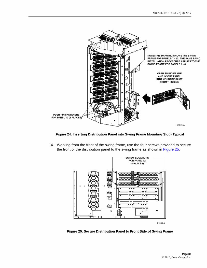
13. Open swing frame and insert the distribution panel into the selected mounting slotfrom the side as shown in Figure 24. Use the three plastic push pins provided tosecure the distribution panel to the rear side of the swing frame.
Warning: The grounding wires are connected to cabinet ground through a common coppergrounding block. Failure to properly tighten the nut on each individual cable grounding studcould result in improper grounding of the cable and result in performance or safety issues.
Note: The push pins install in the corners of the panel and are used to hold thepanel in place within the swing frame prior to installing the mounting screws. Eachpanel is V-shaped and one push pin is provided for each corner.
CABLE
USE GROMMETFOR SMALLER
DIAMETER CABLES
COVERPLATE
CLAMPS
SCREWS
21636-B
SPACER
Page 32© 2016, CommScope, Inc.
ADCP-96-181 • Issue 2 • July 2016
GASIC THE
Figure 24. Inserting Distribution Panel into Swing Frame Mounting Slot - Typical
14. Working from the front of the swing frame, use the four screws provided to securethe front of the distribution panel to the swing frame as shown in Figure 25.
Figure 25. Secure Distribution Panel to Front Side of Swing Frame
OPEN SWING FRAMEAND INSERT PANEL
INTO MOUNTING SLOTFROM THIS SIDE
24575-A
NOTE: THIS DRAWING SHOWS THE SWINFRAME FOR PANELS 7 - 12. THE SAME BINSTALLATION PROCEDURE APPLIES TOSWING FRAME FOR PANELS 1 - 6.
PUSH-PIN FASTENERS FOR PANEL 12 (3 PLACES)
21364-A
SCREW LOCATIONSFOR PANEL 12
(4 PLACES)
Page 33© 2016, CommScope, Inc.

ADCP-96-181 • Issue 2 • July 2016
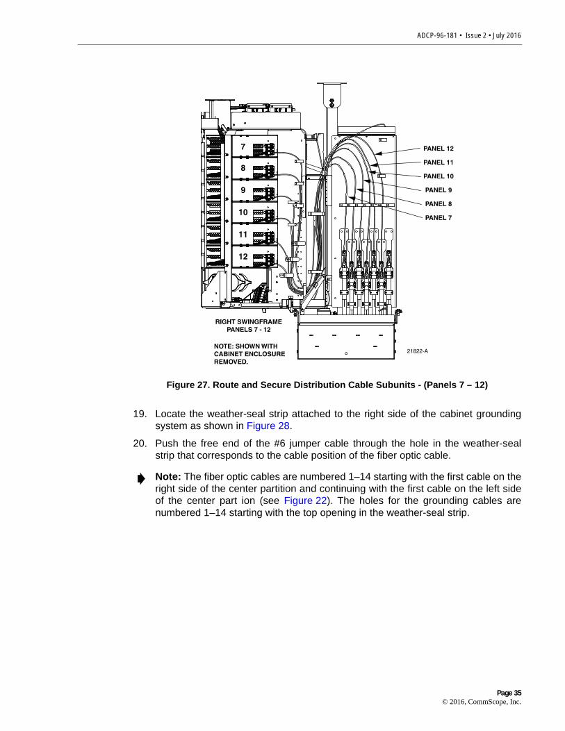
15. Route and secure the distribution cable subunit fibers within the cabinet as shownin Figure 26 and Figure 27.
Figure 26. Route and Secure Distribution Cable Subunits - (Panels 1 – 6)
16. Slowly rotate the swing frame to the closed position while verifying that the subunitfibers do not kink or bind. Re-adjust the subunit fibers if necessary to preventbinding.
17. Reinstall the back access cover that was removed in step 1. Use the 3/16-inchhex-key to tighten the screws that secure the access cover to the cabinet groundspacer/riser.
18. If a grounding stud is provided on the cable, connect a #6 AWG jumper cable(provided with panel) to the cable grounding stud.
1
2
3
4
5
6
FEEDER 1
PANEL 6
PANEL 5
PANEL 4
PANEL 3
PANEL 2
PANEL 1
21801-A
NOTE: SHOWN WITHCABINET ENCLOSUREREMOVED.
LEFT SWINGFRAMEPANELS 1 - 6
Page 34© 2016, CommScope, Inc.
ADCP-96-181 • Issue 2 • July 2016
Figure 27. Route and Secure Distribution Cable Subunits - (Panels 7 – 12)
19. Locate the weather-seal strip attached to the right side of the cabinet groundingsystem as shown in Figure 28.
20. Push the free end of the #6 jumper cable through the hole in the weather-sealstrip that corresponds to the cable position of the fiber optic cable.
Note: The fiber optic cables are numbered 1–14 starting with the first cable on theright side of the center partition and continuing with the first cable on the left sideof the center part ion (see Figure 22). The holes for the grounding cables arenumbered 1–14 starting with the top opening in the weather-seal strip.
7
8
9
10
11
12
PANEL 12
PANEL 11
PANEL 10
PANEL 9
PANEL 8
PANEL 7
21822-ANOTE: SHOWN WITHCABINET ENCLOSUREREMOVED.
RIGHT SWINGFRAMEPANELS 7 - 12
Page 35© 2016, CommScope, Inc.

ADCP-96-181 • Issue 2 • July 2016
Figure 28. Cable Grounding System - Interior View
21. Open the grounding system access cover located on the rear side of the cabinetas shown in Figure 29.
22. Identify the grounding stud that corresponds to the position of the fiber optic cable.
23. Connect the grounding jumper cable to the grounding stud identified in step 22.
24. Tighten the grounding stud nut to 30 to 35 lbs force-inches (3.4 to 4.0 Nm) oftorque.
25. Close the cable grounding system access door and secure using the 216B tool.
Note: A label is provided on the back of the access cover that indicates thegrounding stud numbers.
Note: Each grounding stud on the left bus bar is equipped with two nuts. Whenconnecting a jumper cable to the left bus bar, place the cable terminal betweenthe two nuts.
Warning: The grounding wires are connected to cabinet ground through a common coppergrounding block. Failure to properly tighten the nut on each individual cable grounding studcould result in improper grounding of the cable and result in performance or safety issues.
21820-A
WEATHER-SEAL STRIP
GROUNDINGSYSTEM
JUMPER CABLE ROUTINGFOR OPTICAL CABLE #8
Page 36© 2016, CommScope, Inc.

ADCP-96-181 • Issue 2 • July 2016
Figure 29. Cable Grounding System - Exterior View
8 ROUTING AND CONNECTING THE SPLITTER OUTPUT FIBERS
The splitter modules are mounted at the top of the 864 termination FDH 3000 cabinet.When a splitter module is initially installed, the output fibers are routed to the storagepanel located at the bottom of the cabinet. At the storage panel, the output fibers aretemporarily “parked” until they are needed. Service to a subscriber is enabled byremoving an unused output fiber from the storage panel, routing it to the appropriatedistribution panel, and then connecting it to the subscriber port.
8.1 Storing The Splitter Output Fibers
Use the following procedure to store the splitter output fibers.
1. Following installation of a splitter module, locate an open connector pack slot inthe storage panel at the bottom of the cabinet.
2. Insert the connector pack into the unused slot in the storage panel.
CABLE 1CABLE 2
CABLE 15CABLE 16
LEFT BUS BARCABLE ASSEMBLY
RIGHT BUS BARCABLE ASSEMBLY
21823-ATIGHTEN TO 30 TO 35LBS FORCE - INCHES
(3.4 TO 4.0 Nm) OF TORQUE
Page 37© 2016, CommScope, Inc.

ADCP-96-181 • Issue 2 • July 2016
3. Use the radius limiters to store any excess fiber slack. Refer to Figure 30 for therouting guidelines.
Figure 30. Routing Splitter Output Fibers for Storage
8.2 Enabling Service To a Subscriber
Use the following procedure to enable service to a subscriber (refer to Figure 31 andFigure 32):
1. Check the designation labels on the cabinet front doors to determine thedistribution panel and port number that corresponds to the address of thesubscriber.
2. Locate the subscriber port on the distribution panel and remove the adapter dustcap.
3. Select and remove an unused splitter output fiber from the storage panel andcarefully work it free of any other fibers.
Warning: Infrared radiation is invisible and can seriously damage the retina of the eye. Do notlook into the ends of any optical fiber. Do not look directly into the optical adapters orconnectors. Exposure to invisible laser radiation may result. An optical power meter should beused to verify active fibers. A protective cap or hood MUST be immediately placed over anyradiating adapter or optical connector to avoid the potential of dangerous amounts of radiationexposure. This practice also prevents dirt particles from entering the adapter or connector.
25477-A
Page 38© 2016, CommScope, Inc.

ADCP-96-181 • Issue 2 • July 2016
4. Remove the ferrule dust cap from the connector and then clean the connector asspecified in the Optical Fiber Systems Cleaning and Mating Instructions (ADCP-90-159).
5. Connect the splitter output fiber connector to the subscriber port.
Figure 31. Routing Splitter Output Fibers - Splitter and Distribution Port on Same Side of Cabinet
6. Use the radius limiters to store any excess fiber slack. When the splitter and thedistribution port are located on the same side of the cabinet (same swing frame),refer to Figure 32 for the routing guidelines. When the splitter and the distributionport on opposite sides of the cabinet (opposite swing frames), refer to Figure 33for the routing guidelines.
25478-A
Page 39© 2016, CommScope, Inc.

ADCP-96-181 • Issue 2 • July 2016
Figure 32. Routing Splitter Output Fibers - Splitter and Distribution Port on Same Side of Cabinet
9 PASS-THROUGH ROUTING PROCEDURE
Pass-through routing is used when it is necessary for a feeder cable optical signal to berouted directly to a distribution port. This involves connecting a patch cord between theterminated feeder cable connector and the appropriate distribution port. Open cabinetdoors and swing frames as needed to access the referenced components.
9.1 Splitter Compartment Pass-Through Routing Procedure
Use the following procedure to route a jumper patch cord between the splittercompartment and one of the distribution panels.
1. Locate an open splitter mounting position.
2. Remove the dust cap assembly from the selected splitter slot.
3. Remove the feeder cable connector from the rear of the splitter compartment (seeFigure 19).
25479-A
Page 40© 2016, CommScope, Inc.

ADCP-96-181 • Issue 2 • July 2016
4. Clean the feeder cable connector as specified in the Optical Fiber SystemsCleaning and Mating Instructions (ADCP-90-159).
5. Reinstall the feeder cable connector at the rear of the splitter compartment.
6. Obtain the optical patch cord (accessory) recommended for the pass-throughconnection.
7. Remove the ferrule dust cap from one of the patch cord connectors and thenclean the connector as specified in the Optical Fiber Connector Wet and DryCleaning Instructions (ADCP-90-159) or by locally approved procedures.
8. Install the patch cord connector in the dust cap assembly as shown in Figure 33.
9. Connect the patch cord connector to the feeder cable connector by inserting thedust cap assembly into the splitter slot as shown in Figure 34.
10. Locate the distribution panel and the optical port to which the pass-through patchcord is to be connected.
11. Refer to the procedures in Section 8.2 to route the pass-through patch cord to thedistribution panel and to connect the patch cord connector to the appropriateoptical port.
Warning: Infrared radiation is invisible and can seriously damage the retina of the eye. Do notlook into the ends of any optical fiber. Do not look directly into the optical adapters orconnectors. Exposure to invisible laser radiation may result. An optical power meter should beused to verify active fibers. A protective cap or hood MUST be immediately placed over anyradiating adapter or optical connector to avoid the potential of dangerous amounts of radiationexposure. This practice also prevents dirt particles from entering the adapter or connector.
Page 41© 2016, CommScope, Inc.

ADCP-96-181 • Issue 2 • July 2016
Figure 33. Installing Patch Cord Connector in Dust Cap Assembly
Figure 34. Inserting Dust Cap Assembly into Splitter Compartment
25481-A
ORIENT CONNECTORSO KEY IS ON BACK SIDE (NOT VISIBLE IN THIS VIEW)
DUST CAP ANDCONNECTOR ASSEMBLY
25480-A
Page 42© 2016, CommScope, Inc.

ADCP-96-181 • Issue 2 • July 2016
9.2 Sliding Adapter Pack Pass-Through Routing Procedure
Use the following procedure to route a jumper patch cord between the feeder cablesliding adapter pack and one of the distribution panels (refer to Figure 35).
1. Locate the appropriate feeder cable connector on the sliding adapter pack.
Figure 35. Adapter Pack Raised to Access Position
2. Pull upward on the small tab on top of the adapter pack and lift the adapter pack tothe position shown in Figure 35.
3. Remove the dust cap from the appropriate bulkhead adapter in the sliding adapterpack.
4. Obtain the optical patch cord (accessory) recommended for the pass-throughconnection.
5. Remove the ferrule dust cap from one of the patch cord connectors and thenclean the connector as specified in the Optical Fiber Connector Wet and DryCleaning Instructions (ADCP-90-159) or by locally approved procedures.
Warning: Infrared radiation is invisible and can seriously damage the retina of the eye. Do notlook into the ends of any optical fiber. Do not look directly into the optical adapters orconnectors. Exposure to invisible laser radiation may result. An optical power meter should beused to verify active fibers. A protective cap or hood MUST be immediately placed over anyradiating adapter or optical connector to avoid the potential of dangerous amounts of radiationexposure. This practice also prevents dirt particles from entering the adapter or connector.
Note: Use catalog# FPCFW-SPSC-P-3.1 for UPC. Use catalog# FPCFW-APSC-P-3.1for APC.
PULL UPWARD ON TAB
REMOVE DUST CAP
INSERT CONNECTOR
21827-A
Page 43© 2016, CommScope, Inc.

ADCP-96-181 • Issue 2 • July 2016
6. Insert the patch cord connector into the bulkhead adapter in the sliding adapterpack.
7. Slide the adapter pack down into the closed position.
8. Route the pass-through patch cord around the radius limiters and up the guidewayto the top of swing frame as shown in Figure 36 (right swing frame) or Figure 37left swing frame.
9. From the top of the swing frame, route the patch cord to the front guideway thatleads to the distribution panels.
10. Locate the distribution panel and the optical port to which the pass-through patchcord is to be connected.
11. Refer to the procedures in Section 8.2 to route the pass-through patch cord to thedistribution panel and to connect the patch cord connector to the appropriateoptical port.
Figure 36. Routing Patch Cord Through Right Swing Frame
25482-A
PASS-THROUGHROUTING FORPATCH CORDS
SLIDINGADAPTER
PACK
Page 44© 2016, CommScope, Inc.

ADCP-96-181 • Issue 2 • July 2016
Figure 37. Routing Patch Cord Through Left Swing Frame
10 MAINTENANCE AND REPAIR PROCEDURES
The 864 termination FDH 3000 cabinet requires no regular maintenance to insurecontinuous and satisfactory operation. Maintenance is limited to repairing or replacingany cabinet components that may be damaged or broken in the course of normaloperation. The following sections provide procedures for repairing or replacingcommon cabinet components. Open cabinet doors and swing frames as needed toaccess the referenced components.
10.1 Painting
Brush-in-cap type bottles of paint are available for touching-up nicks and scratches inthe factory coat of paint. Lightly sand the area to be painted and then clean itthoroughly to remove any dirt, dust, or foreign matter. Shake the paint bottle untilthoroughly mixed and then apply a light coat of paint to the damaged area using thesmall brush attached to the cap. Wait until the paint is dry and then apply a second coatif necessary. When finished painting, replace the paint bottle cap and tighten securely.
10.2 Distribution Panel Adapter Replacement
Replacement adapters are available for the distribution panels. Use the followingprocedure to remove and replace a damaged adapter:
1. Disconnect the splitter connector from the front side of the broken adapter asshown in Figure 38 and install a dust cap on the connector.
25484-A
PASS-THROUGHROUTING FORPATCH CORDS
SLIDINGADAPTER
PACK
Page 45© 2016, CommScope, Inc.

ADCP-96-181 • Issue 2 • July 2016
Figure 38. Adapter Removal and Replacement
2. Unlatch and fully open the cabinet swing frame to provide access to the rear sideof the distribution panel.
3. Disconnect the distribution connector from the rear side of the broken adapter andinstall a dust cap on the connector.
4. Working from the rear side of the distribution panel, use the SC adapter removaltool (catalog # FCC-ACC003) to depress the two metal tabs that retain the adapterin the panel. Then push forward on the adapter until it pops out of the panel.
5. Discard the damaged adapter.
6. Install the replacement adapter by inserting it into the distribution panel from thefront and then pushing it toward the back until it snaps into place.
Warning: Infrared radiation is invisible and can seriously damage the retina of the eye. Do notlook into the ends of any optical fiber. Do not look directly into the optical adapters orconnectors. Exposure to invisible laser radiation may result. An optical power meter should beused to verify active fibers. A protective cap or hood MUST be immediately placed over anyradiating adapter or optical connector to avoid the potential of dangerous amounts of radiationexposure. This practice also prevents dirt particles from entering the adapter or connector.
Caution: Use extreme care when removing a connector or an adapter from thedistribution panel to avoid macro bending the adjacent fibers.
Note: Make sure the keyway in the replacement adapter is facing in the samedirection as the keyways in the rest of the adapters installed in the distributionpanel.
DISTRIBUTIONCONNECTOR
SPLITTERCONNECTOR
METAL TAB(TOP AND BOTTOM)
ADAPTER21366-C
NOTE: AFTER REMOVING THE CONNECTORFROM THE ADAPTER, INSTALL A DUST CAPON THE CONNECTOR TO KEEP THE ENDFACECLEAN AND TO PREVENT DAMAGE
Page 46© 2016, CommScope, Inc.

ADCP-96-181 • Issue 2 • July 2016
7. Clean the distribution and splitter fiber connectors as specified in the Optical FiberSystems Cleaning and Mating Instructions (ADCP-90-159).
8. Connect the distribution connector to the rear side of the replacement adapter.
9. Close the cabinet swing frame.
10. Connect the splitter connector to the front side of the replacement adapter.
10.3 Splitter Compartment Adapter Replacement
Replacement adapter assemblies are available for the splitter compartment. Use thefollowing procedure to remove and replace a damaged adapter assembly:
1. Unlatch and fully open the cabinet swing frame to provide access to the both thefront and rear side of the splitter compartment.
2. Remove the splitter or the dust cap assembly from the front side of the brokenadapter assembly.
3. Remove the feeder cable connector from the rear side of the broken adapterassembly as shown in Figure 39 and install a dust cap on the connector.
Figure 39. Removing the Feeder Cable Connector
4. With a screw driver, remove the four upper screws and cover plate as shown inFigure 40. Do not discard.
Warning: Infrared radiation is invisible and can seriously damage the retina of the eye. Do notlook into the ends of any optical fiber. Do not look directly into the optical adapters orconnectors. Exposure to invisible laser radiation may result. An optical power meter should beused to verify active fibers. A protective cap or hood MUST be immediately placed over anyradiating adapter or optical connector to avoid the potential of dangerous amounts of radiationexposure. This practice also prevents dirt particles from entering the adapter or connector.
25483-A
FEEDER CABLECONNECTOR
DUST CAPOR SPLITTER
REAR VIEW OFSPLITTER COMPARTMENT
Page 47© 2016, CommScope, Inc.

ADCP-96-181 • Issue 2 • July 2016
Figure 40. Removing the Cover Plate
5. Disassemble, from upper clips, top slide with damaged adapter, and discard, asshown in Figure 41.
Figure 41. Removing Damaged Adapter
6. Install the replacement top side assembly in the splitter compartment. Remove thedust cap from the replacement adapter and install. Note key orientation(Figure 42).
25487-A
COVERPLATE
25488-A
DAMAGED ADAPTER
Page 48© 2016, CommScope, Inc.

ADCP-96-181 • Issue 2 • July 2016
Figure 42. Installing Replacement Adapter
7. Clean the feeder cable connector as specified in the Optical Fiber SystemsCleaning and Mating Instructions (ADCP-90-159).
8. Connect the feeder cable connector to the rear side of the replacement adapterassembly.
9. Connect the dust cap or splitter to the front side of the replacement adapterassembly.
10. Close the cabinet swing frame.
10.4 Replacing a Damaged Fiber or Connector
A damaged fiber or connector can usually be replaced. The following describes thevarious replacement options.
• Damaged Splitter Output Fiber: Replace the splitter output fiber from theconnector all the way back into the splitter. Splice a new pigtail (use only pigtailswith bend-optimized fiber) to the remaining section of the old fiber within thesplitter chassis. This procedure requires removing and disassembling the splitterto insert a splice chip and to perform the splice. A kit is available from ADC. Referto ADCP-96-034 for the procedure.
• Damaged Distribution or Feeder Connector: Replace the connector at the bulkheadadapter if just the connector alone is damaged. Use a field-installable connectorreplacement kit. Refer to Section 10.4.1 for the replacement procedures.
25501-A
REPLACEMENTADAPTER
Page 49© 2016, CommScope, Inc.

ADCP-96-181 • Issue 2 • July 2016
10.4.1 Splitter Output Fiber Connector Replacement
Use the following procedure to replace the connector:
1. Disconnect the damaged connector and the good connector from the adapter andinstall a dust cap on the good connector.
2. Replace the damaged connector as specified in the procedures provided with thefield-installable connector replacement kit.
3. Clean both connectors as specified in the Optical Fiber Connector Wet and DryCleaning Instructions (ADCP-90-159) or by locally approved procedures.
4. Reconnect the good connector and the replacement connector to the adapter.
10.5 Door Gasket Replacement
Damaged door gaskets may be replaced using the door gasket kit which includes a rollof gasket material. The ideal installation temperature for the adhesive used on thereplacement gaskets is between 60 and 100 ºF (16 and 38 ºC). Installation is notrecommended if the temperature is below 50 ºF (10 ºC). Remove any damagedsections of gasket material from the door. If necessary, use a citrus based adhesivecleaner to remove any adhesive that may stay attached to the door. Cut replacementlengths of gasket material from the roll as needed. Remove the paper backing toexpose the adhesive and then carefully apply the replacement gasket to the door. Takecare not to leave any gaps between the meeting sections of the gasket strips.
10.6 Door Replacement
Damaged cabinet doors may be replaced using the door replacement kit. Use thefollowing procedure to remove and replace the cabinet doors:
1. Open both cabinet doors and lock them in the open position as shown inFigure 43.
2. Use a 3/8-inch nut driver to remove the two locking nuts that secure the groundingstrap lug to the right door. Save nuts for reuse.
3. Use a 3/8-inch nut driver and wrench to remove the locking nut, brass bushing,and capscrew that secures the door linkage to the door bracket as shown inFigure 44. Save the nut, bushing, and capscrew for reuse.
4. Use a 3/8-inch nut driver to remove the three locking nuts that secure each hingeto the door. Save nuts for reuse.
Warning: Infrared radiation is invisible and can seriously damage the retina of the eye. Do notlook into the ends of any optical fiber. Do not look directly into the optical adapters orconnectors. Exposure to invisible laser radiation may result. An optical power meter should beused to verify active fibers. A protective cap or hood MUST be immediately placed over anyradiating adapter or optical connector to avoid the potential of dangerous amounts of radiationexposure. This practice also prevents dirt particles from entering the adapter or connector.
Page 50© 2016, CommScope, Inc.

ADCP-96-181 • Issue 2 • July 2016
Figure 43. Door Replacement
Note: Support the door as the last nuts are removed to prevent the door fromfalling.
25485-A
DOORHINGES
DOORHINGES
GROUNDINGSTRAP LUG
GROUNDINGSTRAP LUG
DOORLINKAGE
DOORLINKAGE
Page 51© 2016, CommScope, Inc.
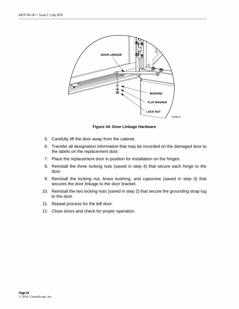
ADCP-96-181 • Issue 2 • July 2016
Figure 44. Door LInkage Hardware
5. Carefully lift the door away from the cabinet.
6. Transfer all designation information that may be recorded on the damaged door tothe labels on the replacement door.
7. Place the replacement door in position for installation on the hinges.
8. Reinstall the three locking nuts (saved in step 4) that secure each hinge to thedoor.
9. Reinstall the locking nut, brass bushing, and capscrew (saved in step 3) thatsecures the door linkage to the door bracket.
10. Reinstall the two locking nuts (saved in step 2) that secure the grounding strap lugto the door.
11. Repeat process for the left door.
12. Close doors and check for proper operation.
21683-A
LOCK NUT
DOOR LINKAGE
BUSHING
FLAT WASHER
Page 52© 2016, CommScope, Inc.

ADCP-96-181 • Issue 2 • July 2016
10.7 Grounding System Terminal Access Procedure
Fiber optic cables with metallic strength members or shields are grounded to acommon grounding system. The grounding system is designed to allow the metallicelements of each cable to be isolated for connection of cable locating equipment. Thegrounding system terminals may be accessed through a small cover located on theside of the cabinet. Use the following procedure to access and isolate the metallicelements of individual cables:
1. Locate the small hinged access cover on the side of the cabinet as shown inFigure 45.
Figure 45. Grounding Block Access Cover
2. Use the 216B tool to remove the screw that secures the access cover in theclosed position.
3. Open the cover and locate the grounding stud that corresponds to the cable to belocated.
Note: A designation label is provided on the access cover for identifying cables.
CABLE 1CABLE 2
CABLE 15CABLE 16
LEFT BUS BARCABLE ASSEMBLY
RIGHT BUS BARCABLE ASSEMBLY
21823-ATIGHTEN TO 30 TO 35LBS FORCE - INCHES
(3.4 TO 4.0 Nm) OF TORQUE
Page 53© 2016, CommScope, Inc.

ADCP-96-181 • Issue 2 • July 2016
4. Remove the stud nut and disconnect the cable so that it is not touching the copperbus bar assembly.
5. Attach cable detection equipment to the isolated grounding cable and completethe cable location procedure.
6. When finished locating cables, reconnect the cable terminal to the grounding stud.
7. Tighten the grounding stud nut to 30 to 35 lbs force-inches. (3.4 to 4.0 Nm) oftorque.
8. Close and secure grounding block access cover.
11 TECHNICAL ASSISTANCE
Contact the Technical Assistance Center (TAC) for technical question. Call800.830.5056 or send an email to [email protected].
Warning: The grounding cables are connected to cabinet ground through the copper groundingblocks. Failure to properly tighten the nut on each individual cable grounding stud could resultin improper grounding of the cable and result in performance or safety issues.
Page 54© 2016, CommScope, Inc.


![TSECET [FDH & B.S.C (MATHEMATICS)] - 2015€¦ · tsecet [fdh & b.s.c (mathematics)] - 2015 jawaharlal nehru technological university hyderabad tsecet [fdh & b.sc ( mathematics)]](https://img.pdfslide.net/doc/110x75/5ea34b6156d5fd4f373845d0/tsecet-fdh-bsc-mathematics-tsecet-fdh-bsc-mathematics.jpg)