Embed Size (px)
Citation preview
FINAL DRAFT UGANDA
STANDARD
FDUS 1746
First Edition 2017-mm-dd
This Final Draft Uganda Standard, FDUS 1746: 2017, Standard Test Method for Vapor Pressure of Petroleum Products (Mini Method), is based on ASTM D5191 − 15, Standard Test Method for Vapor Pressure of Petroleum Products (Mini Method), Copyright ASTM International, 100 Barr Harbor Drive, West Conshohocken, PA 19428, USA, pursuant to license with ASTM International
Reference number FDUS 1746: 2017
© UNBS 2017
Standard Test Method for Vapor Pressure of Petroleum Products (Mini Method)
DRAFT FO
R PUBLIC
REVIE
W
FDUS 1746: 2017
ii © UNBS 2017 - All rights reserved
Compliance with this standard does not, of itself confer immunity from legal obligations
A Uganda Standard does not purport to include all necessary provisions of a contract. Users are responsible for its correct application
© UNBS 2017
All rights reserved. Unless otherwise specified, no part of this publication may be reproduced or utilised in any form or by any means, electronic or mechanical, including photocopying and microfilm, without prior written permission from UNBS.
Requests for permission to reproduce this document should be addressed to
The Executive Director Uganda National Bureau of Standards P.O. Box 6329 Kampala Uganda Tel: +256 417 333 250/1/2/3 Fax:+ 256 414 286 123 E-mail: [email protected] Web: www.unbs.go.ug
This Final Draft Uganda Standard, FDUS 1746: 2017, Standard Test Method for Vapor Pressure of Petroleum Products (Mini Method), is based on ASTM D5191 − 15, Standard Test Method for Vapor Pressure of Petroleum Products (Mini Method), Copyright ASTM International, 100 Barr Harbor Drive, West Conshohocken, PA 19428, USA, pursuant to license with ASTM International
DRAFT FO
R PUBLIC
REVIE
W
FDUS 1746: 2017
© UNBS 2017 - All rights reserved iii
National foreword
Uganda National Bureau of Standards (UNBS) is a parastatal under the Ministry of Trade, Industry and Cooperatives established under Cap 327, of the Laws of Uganda, as amended. UNBS is mandated to co-ordinate the elaboration of standards and is
(a) a member of International Organisation for Standardisation (ISO) and
(b) a contact point for the WHO/FAO Codex Alimentarius Commission on Food Standards, and
(c) the National Enquiry Point on TBT Agreement of the World Trade Organisation (WTO).
The work of preparing Uganda Standards is carried out through Technical Committees. A Technical Committee is established to deliberate on standards in a given field or area and consists of representatives of consumers, traders, academicians, manufacturers, government and other stakeholders.
Draft Uganda Standards adopted by the Technical Committee are widely circulated to stakeholders and the general public for comments. The committee reviews the comments before recommending the draft standards for approval and declaration as Uganda Standards by the National Standards Council.
This Final Draft Uganda Standard, FDUS 1746: 2017, Standard Test Method for Vapor Pressure of Petroleum Products (Mini Method), is based on ASTM D5191 − 15, Standard Test Method for Vapor Pressure of Petroleum Products (Mini Method), Copyright ASTM International, 100 Barr Harbor Drive, West Conshohocken, PA 19428, USA, pursuant to license with ASTM International.
The committee responsible for this document is Technical Committee UNBS/TC 16, Petroleum, Subcommittee SC 1, Petroleum and petrochemical products.
Wherever the words, “ASTM Standard" appear, they should be replaced by "Uganda Standard."
DRAFT FO
R PUBLIC
REVIE
W
Designation: D5191 − 15
Standard Test Method forVapor Pressure of Petroleum Products (Mini Method)1
This standard is issued under the fixed designation D5191; the number immediately following the designation indicates the year oforiginal adoption or, in the case of revision, the year of last revision. A number in parentheses indicates the year of last reapproval. Asuperscript epsilon (´) indicates an editorial change since the last revision or reapproval.
This standard has been approved for use by agencies of the U.S. Department of Defense.
1. Scope*
1.1 This test method covers the use of automated vaporpressure instruments to determine the total vapor pressureexerted in vacuum by air-containing, volatile, liquid petroleumproducts, including automotive spark-ignition fuels with orwithout oxygenates (see Note 1). This test method is suitablefor testing samples with boiling points above 0 °C (32 °F) thatexert a vapor pressure between 7 kPa and 130 kPa (1.0 psi and18.6 psi) at 37.8 °C (100 °F) at a vapor-to-liquid ratio of 4:1.Measurements are made on liquid sample sizes in the rangefrom 1 mL to 10 mL. No account is made for dissolved waterin the sample.
NOTE 1—An interlaboratory study was conducted in 2008 involving 11different laboratories submitting 15 data sets and 15 different samples ofethanol-fuel blends containing 25 volume %, 50 volume %, and 75volume % ethanol. The results indicated that the repeatability limits ofthese samples are with in the published repeatability of this test method.on this basis, it can be concluded that D5191 is applicable to ethanol-fuelblends such as Ed75 and Ed85 (Specification D5798) and other ethanol-fuel blends with greater than 10 v% ethanol. See ASTM RR: D02–1694filed with ASTM for supporting data.2
NOTE 2—Samples can also be tested at other vapor-to-liquid ratios,temperatures, and pressures, but the precision and bias statements need notapply.
NOTE 3—The interlaboratory studies conducted in 1988, 1991, and2003 to determine the precision statements in Test Method D5191 did notinclude any crude oil in the sample sets. Test Method D6377, as well asIP 481, have been shown to be suitable for vapor pressure measurementsof crude oils.
1.1.1 Some gasoline-oxygenate blends may show a hazewhen cooled to 0 °C to 1 °C. If a haze is observed in 8.5, itshall be indicated in the reporting of results. The precision andbias statements for hazy samples have not been determined(see Note 15).
1.2 This test method is suitable for calculation of the dryvapor pressure equivalent (DVPE) of gasoline and gasoline-
oxygenate blends by means of a correlation equation (see Eq 1in 14.2). The calculated DVPE very closely approximates thedry vapor pressure that would be obtained on the same materialwhen tested by Test Method D4953.
1.3 The values stated in SI units are regarded as standard.The inch-pound units given in parentheses are provided forinformation only.
1.4 WARNING—Mercury has been designated by manyregulatory agencies as a hazardous material that can causecentral nervous system, kidney and liver damage. Mercury, orits vapor, may be hazardous to health and corrosive tomaterials. Caution should be taken when handling mercury andmercury containing products. See the applicable product Ma-terial Safety Data Sheet (MSDS) for details and EPA’s website– http://www.epa.gov/mercury/faq.htm - for additional infor-mation. Users should be aware that selling mercury and/ormercury containing products into your state or country may beprohibited by law.
1.5 This standard does not purport to address all of thesafety concerns, if any, associated with its use. It is theresponsibility of the user of this standard to establish appro-priate safety and health practices and determine the applica-bility of regulatory limitations prior to use. For specific safetywarning statements, see 7.2 through 7.8.
2. Referenced Documents
2.1 ASTM Standards:3
D2892 Test Method for Distillation of Crude Petroleum(15-Theoretical Plate Column)
D4057 Practice for Manual Sampling of Petroleum andPetroleum Products
D4953 Test Method for Vapor Pressure of Gasoline andGasoline-Oxygenate Blends (Dry Method)
D5798 Specification for Ethanol Fuel Blends for Flexible-Fuel Automotive Spark-Ignition Engines
D6299 Practice for Applying Statistical Quality Assuranceand Control Charting Techniques to Evaluate Analytical
1 This test method is under the jurisdiction of ASTM Committee D02 onPetroleum Products, Liquid Fuels, and Lubricants and is the direct responsibility ofSubcommittee D02.08 on Volatility.
Current edition approved Oct. 1, 2015. Published October 2015. Originallyapproved in 1991. Last previous edition approved in 2013 as D5191 – 13. DOI:10.1520/D5191-15.
2 Supporting data have been filed at ASTM International Headquarters and maybe obtained by requesting Research Report RR:D02-1694.
3 For referenced ASTM standards, visit the ASTM website, www.astm.org, orcontact ASTM Customer Service at [email protected]. For Annual Book of ASTMStandards volume information, refer to the standard’s Document Summary page onthe ASTM website.
*A Summary of Changes section appears at the end of this standard
Copyright © ASTM International, 100 Barr Harbor Drive, PO Box C700, West Conshohocken, PA 19428-2959. United States
This international standard was developed in accordance with internationally recognized principles on standardization established in the Decision on Principles for theDevelopment of International Standards, Guides and Recommendations issued by the World Trade Organization Technical Barriers to Trade (TBT) Committee.
1
Copyright by ASTM Int'l (all rights reserved); Wed Apr 19 06:11:48 EDT 2017Downloaded/printed byUganda MOU - Online Access (Uganda MOU - Online Access) pursuant to License Agreement. No further reproductions authorized.
DRAFT FO
R PUBLIC
REVIE
W
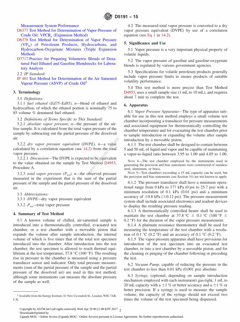
Measurement System PerformanceD6377 Test Method for Determination of Vapor Pressure of
Crude Oil: VPCRx (Expansion Method)D6378 Test Method for Determination of Vapor Pressure
(VPX) of Petroleum Products, Hydrocarbons, andHydrocarbon-Oxygenate Mixtures (Triple ExpansionMethod)
D7717 Practice for Preparing Volumetric Blends of Dena-tured Fuel Ethanol and Gasoline Blendstocks for Labora-tory Analysis
2.2 IP Standard:IP 481 Test Method for Determination of the Air Saturated
Vapour Pressure (ASVP) of Crude Oil4
3. Terminology
3.1 Definitions:3.1.1 fuel ethanol (Ed75–Ed85), n—blend of ethanol and
hydrocarbon, of which the ethanol portion is nominally 75 to85 volume % denatured fuel ethanol.
3.2 Definitions of Terms Specific to This Standard:3.2.1 absolute vapor pressure, n—the pressure of the air-
free sample. It is calculated from the total vapor pressure of thesample by subtracting out the partial pressure of the dissolvedair.
3.2.2 dry vapor pressure equivalent (DVPE), n—a valuecalculated by a correlation equation (see 14.2) from the totalvapor pressure.
3.2.2.1 Discussion—The DVPE is expected to be equivalentto the value obtained on the sample by Test Method D4953,Procedure A.
3.2.3 total vapor pressure (Ptot), n—the observed pressuremeasured in the experiment that is the sum of the partialpressure of the sample and the partial pressure of the dissolvedair.
3.3 Abbreviations:3.3.1 DVPE—dry vapor pressure equivalent
3.3.2 Ptot—total vapor pressure
4. Summary of Test Method
4.1 A known volume of chilled, air-saturated sample isintroduced into a thermostatically controlled, evacuated testchamber, or a test chamber with a moveable piston thatexpands the volume after sample introduction, the internalvolume of which is five times that of the total test specimenintroduced into the chamber. After introduction into the testchamber, the test specimen is allowed to reach thermal equi-librium at the test temperature, 37.8 °C (100 °F). The resultingrise in pressure in the chamber is measured using a pressuretransducer sensor and indicator. Only total pressure measure-ments (sum of the partial pressure of the sample and the partialpressure of the dissolved air) are used in this test method,although some instruments can measure the absolute pressureof the sample as well.
4.2 The measured total vapor pressure is converted to a dryvapor pressure equivalent (DVPE) by use of a correlationequation (see Eq 1 in 14.2).
5. Significance and Use
5.1 Vapor pressure is a very important physical property ofvolatile liquids.
5.2 The vapor pressure of gasoline and gasoline-oxygenateblends is regulated by various government agencies.
5.3 Specifications for volatile petroleum products generallyinclude vapor pressure limits to ensure products of suitablevolatility performance.
5.4 This test method is more precise than Test MethodD4953, uses a small sample size (1 mL to 10 mL), and requiresabout 7 min to complete the test.
6. Apparatus
6.1 Vapor Pressure Apparatus—The type of apparatus suit-able for use in this test method employs a small volume testchamber incorporating a transducer for pressure measurementsand associated equipment for thermostatically controlling thechamber temperature and for evacuating the test chamber priorto sample introduction or expanding the volume after sampleintroduction by a moveable piston.
6.1.1 The test chamber shall be designed to contain between5 and 50 mL of liquid and vapor and be capable of maintaininga vapor-to-liquid ratio between 3.95 to 1.00 and 4.05 to 1.00.
NOTE 4—The test chamber employed by the instruments used ingenerating the precision and bias statements were constructed of stainlesssteel, aluminum, or brass.
NOTE 5—Test chambers exceeding a 15 mL capacity can be used, butthe precision and bias statements (see Section 16) are not known to apply.
6.1.2 The pressure transducer shall have a minimum opera-tional range from 0 kPa to 177 kPa (0 psi to 25.7 psi) with aminimum resolution of 0.1 kPa (0.01 psi) and a minimumaccuracy of 60.8 kPa (60.12 psi). The pressure measurementsystem shall include associated electronics and readout devicesto display the resulting pressure reading.
6.1.3 A thermostatically controlled heater shall be used tomaintain the test chamber at 37.8 °C 6 0.1 °C (100 °F 6
0.2 °F) for the duration of the vapor pressure measurement.6.1.4 A platinum resistance thermometer shall be used for
measuring the temperature of the test chamber with a resolu-tion of 0.1 °C (0.2 °F) and an accuracy of 0.1 °C (0.2 °F).
6.1.5 The vapor pressure apparatus shall have provisions forintroduction of the test specimen into an evacuated testchamber, or into a test chamber by a moveable piston, and forthe cleaning or purging of the chamber following or precedingthe test.
6.2 Vacuum Pump, capable of reducing the pressure in thetest chamber to less than 0.01 kPa (0.001 psi) absolute.
6.3 Syringe, (optional, depending on sample introductionmechanism employed with each instrument) gas-tight, 1 mL to20 mL capacity with a 61 % or better accuracy and a 61 % orbetter precision. If a syringe is used to measure the samplevolume, the capacity of the syringe should not exceed twotimes the volume of the test specimen being dispensed.
4 Available from the Energy Institute, 61 New Cavendish St., London, WIG 7AR,U.K.
D5191 − 15
2
Copyright by ASTM Int'l (all rights reserved); Wed Apr 19 06:11:48 EDT 2017Downloaded/printed byUganda MOU - Online Access (Uganda MOU - Online Access) pursuant to License Agreement. No further reproductions authorized.
DRAFT FO
R PUBLIC
REVIE
W
6.4 Iced Water Bath, Refrigerator, or Air Bath, for chillingthe samples and syringe to temperatures between 0 °C to 1 °C(32°F to 34 °F).
6.5 Pressure Measuring Device, capable of measuring localstation pressure with an accuracy of 0.20 kPa (0.03 psi), orbetter, at the same elevation relative to sea level as theapparatus in the laboratory.
6.5.1 When a mercury barometer is not used as the pressuremeasuring device, the calibration of the pressure measuringdevice employed shall be periodically checked (with traceabil-ity to a nationally recognized standard) to ensure that thedevice remains within the required accuracy specified in 6.5.
6.6 McLeod Vacuum Gage or Calibrated Electronic VacuumMeasuring Device for Calibration, to cover at least the rangefrom 0.01 kPa to 0.67 kPa (0.1 mm Hg to 5 mm Hg). Thecalibration of the electronic vacuum measuring device shall beregularly verified in accordance with the annex section onVacuum Sensors (A6.3) of Test Method D2892.
7. Reagents and Materials
7.1 Purity of Reagents—Use chemicals of at least 99 %purity for verification of instrument performance (see Section11). Unless otherwise indicated, it is intended that all reagentsconform to the specifications of the Committee on AnalyticalReagents of the American Chemical Society where suchspecifications are available.5 Lower purities can be used,provided it is first ascertained that the reagent is of sufficientpurity to permit its use without lessening the accuracy of thedetermination.
7.1.1 The chemicals in sections 7.2, 7.3, 7.4, 7.7, and 7.8(blended by mass with pentane) are suggested for verificationof instrument performance (see Section 11), based on thereference fuels analyzed in the 2003 interlaboratory study(ILS)6 (see Table 1) and 2014 interlaboratory study (ILS)7(see
Table 2). Such reference fuels are not to be used for instrumentcalibration. Table 1 and Table 2 identify the accepted referencevalue (ARV) and uncertainty limits, as well as the acceptabletesting range for each of the reference fuels listed.
NOTE 6—Verification fluids reported by 28 of the 29 D5191 data setparticipants in the 2003 ILS6 included the following (with number of datasets identified in parenthesis): 2,2-dimethylbutane (18), cyclopentane (5),pentane (2), 2,3-dimethylbutane (1), 3-methylpentane (1), and methanol(1).
7.2 Cyclopentane, (Warning—Cyclopentane is flammableand a health hazard).
7.3 2,2-Dimethylbutane, (Warning—2,2-dimethylbutane isflammable and a health hazard).
7.4 2,3-Dimethylbutane, (Warning—2,3-dimethylbutane isflammable and a health hazard).
7.5 Methanol, (Warning—Methanol is flammable and ahealth hazard).
7.6 2-Methylpentane, (Warning—2-methylpentane is flam-mable and a health hazard).
7.7 Pentane, (Warning—Pentane is flammable and a healthhazard).
7.8 Toluene, (Warning—Toluene is flammable and a healthhazard).
8. Sampling
8.1 General Requirements:8.1.1 The extreme sensitivity of vapor pressure measure-
ments to losses through evaporation and the resulting changesin composition is such as to require the utmost precaution andthe most meticulous care in the drawing and handling ofsamples.
8.1.2 Obtain samples and test specimens in accordance withPractice D4057, except do not use the “Sampling by WaterDisplacement” section for fuels containing oxygenates. Useeither 250 mL or 1 L (1 qt) sized containers filled between70 % and 80 % with sample. For best testing precision(reproducibility), it is recommended that 1 L sized containersbe used.
NOTE 7—The current precision statements were derived from the 2003ILS6 using samples in 250 mL and 1 L (1 qt) clear glass containers.However, samples in containers of other sizes, as prescribed in PracticeD4057, may be used with the same ullage requirement if it is recognizedthat the precision can be affected. The differences in precision resultsobtained from 250 mL and 1 L containers were found to be statistically
5 Reagent Chemicals, American Chemical Society Specifications, AmericanChemical Society, Washington, DC. For Suggestions on the testing of reagents notlisted by the American Chemical Society, see Annual Standards for LaboratoryChemicals, BDH Ltd., Poole, Dorset, U.K., and the United States Pharmacopeiaand National Formulary, U.S. Pharmacopeial Convention, Inc. (USPC), Rockville,MD.
6 Supporting data have been filed at ASTM International Headquarters and maybe obtained by requesting Research Report RR:D02-1619. Contact ASTM CustomerService at [email protected].
7 Supporting data have been filed at ASTM International Headquarters and maybe obtained by requesting Research Report RR:D02-1805. Contact ASTM CustomerService at [email protected].
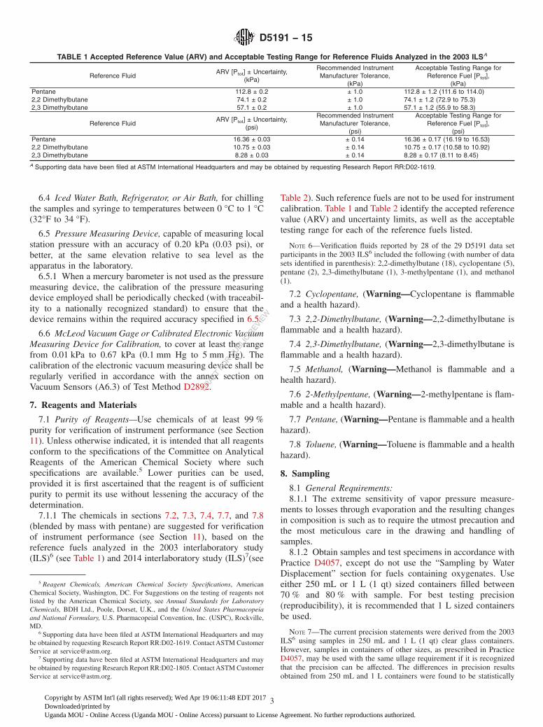
TABLE 1 Accepted Reference Value (ARV) and Acceptable Testing Range for Reference Fluids Analyzed in the 2003 ILSA
Reference FluidARV [Ptot] ± Uncertainty,
(kPa)
Recommended InstrumentManufacturer Tolerance,
(kPa)
Acceptable Testing Range forReference Fuel [Ptot],
(kPa)Pentane 112.8 ± 0.2 ± 1.0 112.8 ± 1.2 (111.6 to 114.0)2,2 Dimethylbutane 74.1 ± 0.2 ± 1.0 74.1 ± 1.2 (72.9 to 75.3)2,3 Dimethylbutane 57.1 ± 0.2 ± 1.0 57.1 ± 1.2 (55.9 to 58.3)
Reference FluidARV [Ptot] ± Uncertainty,
(psi)
Recommended InstrumentManufacturer Tolerance,
(psi)
Acceptable Testing Range forReference Fuel [Ptot],
(psi)Pentane 16.36 ± 0.03 ± 0.14 16.36 ± 0.17 (16.19 to 16.53)2,2 Dimethylbutane 10.75 ± 0.03 ± 0.14 10.75 ± 0.17 (10.58 to 10.92)2,3 Dimethylbutane 8.28 ± 0.03 ± 0.14 8.28 ± 0.17 (8.11 to 8.45)
A Supporting data have been filed at ASTM International Headquarters and may be obtained by requesting Research Report RR:D02-1619.
D5191 − 15
3
Copyright by ASTM Int'l (all rights reserved); Wed Apr 19 06:11:48 EDT 2017Downloaded/printed byUganda MOU - Online Access (Uganda MOU - Online Access) pursuant to License Agreement. No further reproductions authorized.
DRAFT FO
R PUBLIC
REVIE
W
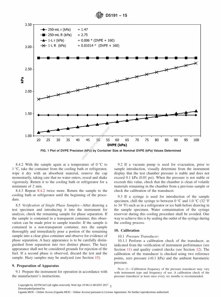
significant, whereas there was no statistically observable bias detectedbetween 250 mL and 1 L containers. See tables in Section 16, as well asFigs. 1 and 2 for more specific details on precision differences as afunction of DVPE value and container size. In general, numerically betterrepeatability values were determined at DVPE values < 85 kPa (12.3 psi)for samples in 1 L containers versus 250 mL containers. Secondly,numerically better reproducibility values were determined for samples in1 L containers versus 250 mL containers for the entire DVPE rangecovered in 16.1.2.
8.1.3 To determine conformance with specifications, orregulations, or both, it may be necessary to prepare laboratoryhand blends of gasoline blendstocks and denatured fuel ethanolfor testing purposes, including vapor pressure. If necessary,then, a hand blend sample, prepared carefully in accordancewith a procedure such as that described in Practice D7717,shall be considered suitable for the performance of this test.This hand blend, once prepared, shall then be consideredequivalent to the ‘sample or samples,’ referred to in 8.1.4through 8.5 of this Sampling section, as well as in subsequentsections of this test method.
8.1.4 Perform the vapor pressure determination on the firsttest specimen withdrawn from a sample container. Do not usethe remaining sample in the container for a second vaporpressure determination. If a second determination is necessary,obtain a new sample.
NOTE 8—The effect of taking more than one test specimen from thesame sample container was evaluated as part of the 2003 ILS.6 A precisioneffect was observed between the first and second replicates taken fromboth the 1 L and 250 mL containers evaluated. The current precisionstatements were derived from the 2003 ILS6 using the first test specimenwithdrawn from 250 mL and 1 L clear glass containers.
8.1.5 Protect samples from excessive temperatures prior totesting. This can be accomplished by storage in an appropriateice bath or refrigerator.
8.1.6 Do not test samples stored in leaky containers. Discardand obtain a new sample if leaks are detected.
8.2 Sampling Handling Temperature—Place the samplecontainer and contents in an ice bath or refrigerator to the 0 °Cto 1 °C (32 °F to 34 °F) range prior to opening the samplecontainer. Allow sufficient time to reach this temperature.
NOTE 9—One way to verify the sample temperature is by directmeasurement of the temperature of a similar liquid in a similar containerplaced in the cooling bath or refrigerator at the same time as the sample.Alternatively, temperature-monitoring studies conducted by laboratories
have determined the minimum amount of time necessary to achieve therequired temperature requirements stated in 8.2, based upon typicalsample receipt temperatures and cooling capacities of the instrumentationemployed by the laboratory on samples included in such studies. Theresults of such studies have subsequently been applied to additionalsamples submitted for analysis. Typical minimum time durations reportedby laboratories have ranged between approximately 30 min and 45 min,however, laboratories choosing this option need to determine the mini-mum cooling time required for their specific operation by conducting theirown temperature-monitoring study.
8.3 Verification of Sample Container Filling—With thesample at a temperature of 0 °C to 1 °C, take the containerfrom the cooling bath or refrigerator, and wipe dry withabsorbent material. If the container is not transparent, unseal itand using a suitable gage, confirm that the sample volumeequals 70 % to 80 % of the container capacity (see Note 10). Ifthe sample is contained in a transparent glass container, verifythat the container is 70 % to 80 % full by suitable means (seeNote 10).
8.3.1 Discard the sample if the container is filled to less than70 %, by volume, of the container capacity.
8.3.2 If the container is more than 80 % by volume full,pour out enough sample to bring the container contents withinthe 70 % to 80 % by volume range. Do not return any sampleto the container once it has been withdrawn.
8.3.3 Reseal the container if necessary, and return thesample container to the cooling bath or refrigerator.
NOTE 10—For non-transparent containers, one way to confirm that thesample volume equals 70 % to 80 % of the container capacity is to use adipstick that has been pre-marked to indicate the 70 % and 80 % containercapacities. The dipstick should be of such material that it shows wettingafter being immersed and withdrawn from the sample. To confirm thesample volume, insert the dipstick into the sample container so that ittouches the bottom of the container at a perpendicular angle, beforeremoving the dipstick. For transparent containers, using a marked ruler orby comparing the sample container to a like container which has the 70 %and 80 % levels clearly marked, has been found suitable.
8.4 Air Saturation of the Sample in the Sample Container:8.4.1 Transparent Containers Only—Since 8.3 does not
require that the sample container be opened to verify thesample capacity, it is necessary to unseal the cap momentarilybefore resealing it, so that samples in transparent containers aretreated the same as samples in non-transparent containers.
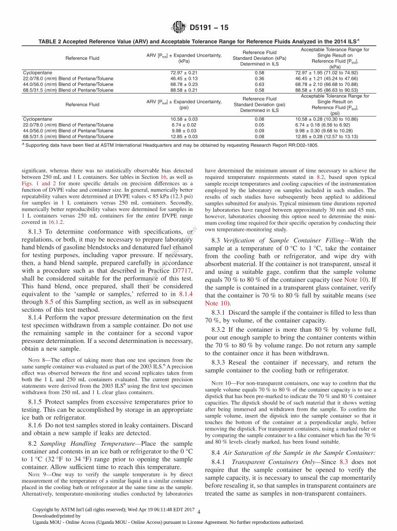
TABLE 2 Accepted Reference Value (ARV) and Acceptable Tolerance Range for Reference Fluids Analyzed in the 2014 ILSA
Reference FluidARV [Ptot] ± Expanded Uncertainty,
(kPa)
Reference FluidStandard Deviation (kPa)
Determined in ILS
Acceptable Tolerance Range forSingle Result on
Reference Fluid [Ptot],(kPa)
Cyclopentane 72.97 ± 0.21 0.58 72.97 ± 1.95 (71.02 to 74.92)22.0/78.0 (m/m) Blend of Pentane/Toluene 46.45 ± 0.13 0.36 46.45 ± 1.21 (45.24 to 47.66)44.0/56.0 (m/m) Blend of Pentane/Toluene 68.78 ± 0.23 0.63 68.78 ± 2.10 (66.68 to 70.88)68.5/31.5 (m/m) Blend of Pentane/Toluene 88.58 ± 0.21 0.58 88.58 ± 1.95 (86.63 to 90.53)
Reference FluidARV [Ptot] ± Expanded Uncertainty,
(psi)
Reference FluidStandard Deviation (psi)
Determined in ILS
Acceptable Tolerance Range forSingle Result on
Reference Fluid [Ptot],(psi)
Cyclopentane 10.58 ± 0.03 0.08 10.58 ± 0.28 (10.30 to 10.86)22.0/78.0 (m/m) Blend of Pentane/Toluene 6.74 ± 0.02 0.05 6.74 ± 0.18 (6.56 to 6.92)44.0/56.0 (m/m) Blend of Pentane/Toluene 9.98 ± 0.03 0.09 9.98 ± 0.30 (9.68 to 10.28)68.5/31.5 (m/m) Blend of Pentane/Toluene 12.85 ± 0.03 0.08 12.85 ± 0.28 (12.57 to 13.13)
A Supporting data have been filed at ASTM International Headquarters and may be obtained by requesting Research Report RR:D02-1805.
D5191 − 15
4
Copyright by ASTM Int'l (all rights reserved); Wed Apr 19 06:11:48 EDT 2017Downloaded/printed byUganda MOU - Online Access (Uganda MOU - Online Access) pursuant to License Agreement. No further reproductions authorized.
DRAFT FO
R PUBLIC
REVIE
W
8.4.2 With the sample again at a temperature of 0 °C to1 °C, take the container from the cooling bath or refrigerator,wipe it dry with an absorbent material, remove the capmomentarily, taking care that no water enters, reseal and shakevigorously. Return it to the cooling bath or refrigerator for aminimum of 2 min.
8.4.3 Repeat 8.4.2 twice more. Return the sample to thecooling bath or refrigerator until the beginning of the proce-dure.
8.5 Verification of Single Phase Samples—After drawing atest specimen and introducing it into the instrument foranalysis, check the remaining sample for phase separation. Ifthe sample is contained in a transparent container, this obser-vation can be made prior to sample transfer. If the sample iscontained in a non-transparent container, mix the samplethoroughly and immediately pour a portion of the remainingsample into a clear glass container and observe for evidence ofphase separation. A hazy appearance is to be carefully distin-guished from separation into two distinct phases. The hazyappearance shall not be considered grounds for rejection of thefuel. If a second phase is observed, discard the test and thesample. Hazy samples may be analyzed (see Section 15).
9. Preparation of Apparatus
9.1 Prepare the instrument for operation in accordance withthe manufacturer’s instructions.
9.2 If a vacuum pump is used for evacuation, prior tosample introduction, visually determine from the instrumentdisplay that the test chamber pressure is stable and does notexceed 0.1 kPa (0.01 psi). When the pressure is not stable orexceeds this value, check that the chamber is clean of volatilematerials remaining in the chamber from a previous sample orcheck the calibration of the transducer.
9.3 If a syringe is used for introduction of the samplespecimen, chill the syringe to between 0 °C and 1.0 °C (32 °Fto 34 °F) such as in a refrigerator or ice bath before drawing inthe sample specimen. Water contamination of the syringereservoir during this cooling procedure shall be avoided. Oneway to achieve this is by sealing the outlet of the syringe duringthe cooling process.
10. Calibration
10.1 Pressure Transducer:10.1.1 Perform a calibration check of the transducer, as
indicated from the verification of instrument performance (seeSection 11) and quality control checks (see Section 12). Thecalibration of the transducer is checked using two referencepoints, zero pressure (<0.1 kPa) and the ambient barometricpressure.
NOTE 11—Calibration frequency of the pressure transducer may varywith instrument type and frequency of use. A calibration check of thepressure transducer at least once every six months is recommended.
FIG. 1 Plot of DVPE Precision (kPa) by Container Size at Nominal DVPE (kPa) Values Determined
D5191 − 15
5
Copyright by ASTM Int'l (all rights reserved); Wed Apr 19 06:11:48 EDT 2017Downloaded/printed byUganda MOU - Online Access (Uganda MOU - Online Access) pursuant to License Agreement. No further reproductions authorized.
DRAFT FO
R PUBLIC
REVIE
W
10.1.2 Connect a McLeod gage or a calibrated electronicvacuum measuring device to the vacuum source in line with thetest chamber (Note 12). Apply vacuum to the test chamber.When the vacuum measuring device registers a pressure lessthan 0.1 kPa (0.8 mm Hg), adjust the indicator to zero or to theactual reading on the vacuum measuring device as dictated bythe instrument design or manufacturer’s instructions.
NOTE 12—Refer to the annex section on Vacuum Sensors (A6.3) of TestMethod D2892 for further details concerning the calibration of electronicvacuum measuring devices and proper maintenance of McLeod gages.
10.1.3 Open the test chamber of the apparatus to atmosphereand observe the corresponding pressure value of the transducer.Ensure that the apparatus is set to display the total pressure andnot a calculated or corrected value. Compare this pressurevalue against the value obtained from the pressure measuringdevice, as the pressure reference standard. If the pressure units(for example, kPa, mm Hg, mbar, etc.) differ between thepressure measuring device employed and the vapor pressureapparatus display, use the appropriate conversion factor toconvert pressure values to the same units, so that the pressurevalues can be compared directly. The pressure measuringdevice shall measure the local station pressure at the sameelevation as the apparatus in the laboratory, at the time ofpressure comparison. (Warning—Many aneroid barometers,such as those used at weather stations and airports, are
pre-corrected to give sea level readings; these must not be usedfor calibration of the apparatus.)
10.1.3.1 For mercury barometers used as the pressure mea-suring device, the barometric pressure reading shall be cor-rected for the change in the density of the mercury columnbetween 0 and the operating temperature and converted to thesame units of pressure as the vapor pressure apparatus display.
10.1.4 Repeat 10.1.2 and 10.1.3 until the zero and baromet-ric pressures read correctly without further adjustments.
10.2 Thermometer—Check the calibration of the platinumresistance thermometer used to monitor the temperature of thetest chamber at least every six months against a nationallytraceable thermometer, such as one that is traceable from theNational Institute of Standards and Technology (NIST).
11. Verification of Instrument Performance
11.1 After calibration, verify the instrument performance asan independent check against the instrument calibration eachday the instrument is in use. For pure compounds (see 7.1) andblends that are prepared from pure compounds, multiple testspecimens may be taken from the same container over time,provided the test specimen is air saturated according to theprocedure given in 8.4, and the spent test specimens are notre-used, in whole or in part. Table 1 and Table 2 provide theaccepted reference value (ARV) and uncertainty limits (at least
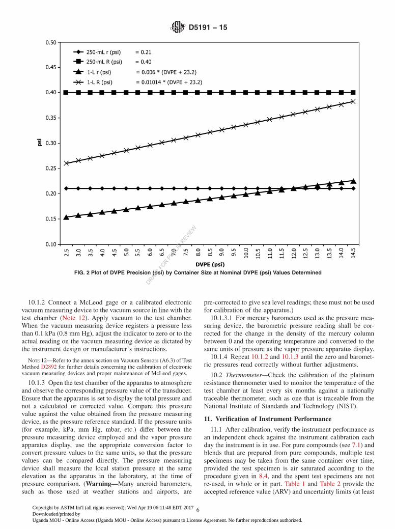
FIG. 2 Plot of DVPE Precision (psi) by Container Size at Nominal DVPE (psi) Values Determined
D5191 − 15
6
Copyright by ASTM Int'l (all rights reserved); Wed Apr 19 06:11:48 EDT 2017Downloaded/printed byUganda MOU - Online Access (Uganda MOU - Online Access) pursuant to License Agreement. No further reproductions authorized.
DRAFT FO
R PUBLIC
REVIE
W
95 % confidence interval) of reference fluids tested in the 2003ILS6 and 2014 ILS,7respectively, which are based on the totalvapor pressure (Ptot) measured. This information from the 2003and 2014 interlaboratory studies was used to establish theacceptable testing or tolerance range for the reference fuels toverify instrument performance.
NOTE 13—In the 2003 ILS, a study was conducted to determine theeffect that the % capacity of material in the 250 mL reference fluidcontainers supplied to the participants had on precision and bias throughreplicate testing from the same bottle. The data indicated that there was nostatistically observable effect on precision and bias for 3 of the 4 referencefluids. For materials with DVPE values >100 kPa, such as pentane, theprecision appears to worsen with diminishing liquid volume in the bottle.It is recommended that if pentane is used, that the % capacity in thecontainer be ≥50 %.
11.2 Values obtained within the acceptable testing or toler-ance range intervals in Table 1 and/or Table 2 indicate that theinstrument is performing at the level deemed acceptable by thisstandard. If values outside the acceptable testing or tolerancerange intervals are obtained, verify the quality of the purecompound(s) and re-check the calibration of the instrument(see Section 10).
12. Quality Control Checks
12.1 After having verified that the instrument is performingproperly, use a quality control (QC) sample that is representa-tive of the fuel(s) routinely tested by the laboratory to confirmthat the instrument is in statistical control following theguidelines given in Practice D6299.
12.2 Record the DVPE value and compare this to thedecision criteria for statistical control. If the result is found tobe outside the decision criteria for statistical control, initiate aninvestigation for root causes.
12.3 Store the QC sample in an environment suitable forlong term storage without sample degradation. See AppendixX2 for guidelines and suggestions for preparing, storing, andisolating QC samples for use in the test.
13. Procedure
13.1 Remove the sample from the cooling bath orrefrigerator, dry the exterior of the container with absorbentmaterial, uncap, and insert a transfer tube or chilled syringe(see 9.3). Draw a bubble-free aliquot of sample into a gas tightsyringe or transfer tube, and deliver this test specimen to thetest chamber as rapidly as possible. The total time betweenopening the chilled sample container and inserting/securing thesyringe into the sealed test chamber shall not exceed 1 min.
13.2 Follow the manufacturer’s instructions for introductionof the test specimen into the test chamber, and for operation ofthe instrument to obtain a total vapor pressure result for the testspecimen.
13.3 Set the instrument to read the result in terms of totalvapor pressure. If the instrument is capable of calculating a dryvapor pressure equivalent value, make sure that only theparameters in 14.2 are used.
14. Calculation
14.1 Record the total vapor pressure reading from theinstrument to the nearest 0.1 kPa (0.01 psi). For instruments
that do not automatically record a stable pressure value,manually record the pressure indicator reading every minute tothe nearest 0.1 kPa. When three successive readings agree towithin 0.1 kPa, record the result to the nearest 0.1 kPa(0.01 psi).
14.2 Calculate the DVPE using Eq 1. Ensure that theinstrument reading used in this equation corresponds to thetotal pressure and has not been corrected by an automaticallyprogrammed correction factor:
DVPE, kPa ~psi! 5 ~0.965 X! 2 A (1)
where:X = measured total vapor pressure in kPa (psi), andA = 3.78 kPa (or 0.548 psi).
NOTE 14—The correlation equation was derived from the results of the1988 cooperative program8 and confirmed in the 1991 interlaboratorystudy.9
14.3 The calculation described by Eq 1 can be accomplishedautomatically by the instrument, if so equipped, and in suchcases the user shall not apply any further corrections.
15. Report
15.1 Report the DVPE value to the nearest 0.1 kPa(0.01 psi) without reference to temperature, along with thevolume container size (250 mL or 1 L) in which the result wasobtained.
15.2 If the sample was observed to be hazy in 8.5, report thetest result as in 15.1, followed by the letter H.
NOTE 15—The precision and bias statements have not been determinedfor hazy samples since these types of samples have not been evaluated aspart of an interlaboratory study.
NOTE 16—The inclusion of the letter H in 15.2 is intended to alert thedata recipient that the sample analyzed was hazy. In the event that alaboratory has a computer system that is incapable of reporting alphanu-meric results in accordance with the requirements in 15.2, it is permissiblefor the laboratory to report the result obtained as in 15.1, along with astatement or annotation that clearly conveys to the data recipient that theanalyzed sample was hazy.
16. Precision and Bias6
16.1 Precision—The precision of this test method wasdeveloped in a 2003 interlaboratory cooperative test program.See X1.1 and X1.3 for additional information concerning thenumber and nature of the sample types and instrumentsevaluated.
16.1.1 Repeatability—The difference between duplicate testresults obtained by the same or potentially different operatorswith the same apparatus in the laboratory using identical testspecimens withdrawn from separate 250 mL or 1 L containersunder constant operating conditions would, in the long run, inthe normal and correct operation of the test method, exceed theconstant value associated with 250 mL containers or the valuecalculated for 1 L containers as follows only in one case in
8 Supporting data (the results of this program) have been filed at ASTMInternational Headquarters and may be obtained by requesting Research ReportRR:D02-1260.
9 Supporting data (the results of this test program) have been filed at ASTMInternational Headquarters and may be obtained by requesting Research ReportRR:D02-1286.
D5191 − 15
7
Copyright by ASTM Int'l (all rights reserved); Wed Apr 19 06:11:48 EDT 2017Downloaded/printed byUganda MOU - Online Access (Uganda MOU - Online Access) pursuant to License Agreement. No further reproductions authorized.
DRAFT FO
R PUBLIC
REVIE
W
twenty across the nominal DVPE range of 17.5 kPa to102.5 kPa (2.5 psi to 14.9 psi).
Container Size Repeatability (r)
250 mL 1.47 kPa (0.21 psi)1 L 0.006 sDVPE1Bd
where:DVPE = kPa (psi) value determined by Eq 1, andB = 160 kPa (23.2 psi).
16.1.2 Reproducibility—The difference between two singleand independent test results obtained by different operatorsworking in different laboratories on identical test materialwithdrawn from 250 mL or 1 L containers would, in the longrun, in the normal and correct operation of the test method,exceed the constant value associated with 250 mL containers orthe value calculated for 1 L containers as follows only in onecase in twenty across the nominal DVPE range of 17.5 kPa to102.5 kPa (2.5 psi to 14.9 psi).
Container Size Reproducibility (R)
250 mL 2.75 kPa (0.40 psi)1 L 0.01014 sDVPE1Bd
where:DVPE = kPa (psi) value determined by Eq 1, andB = 160 kPa (23.2 psi).
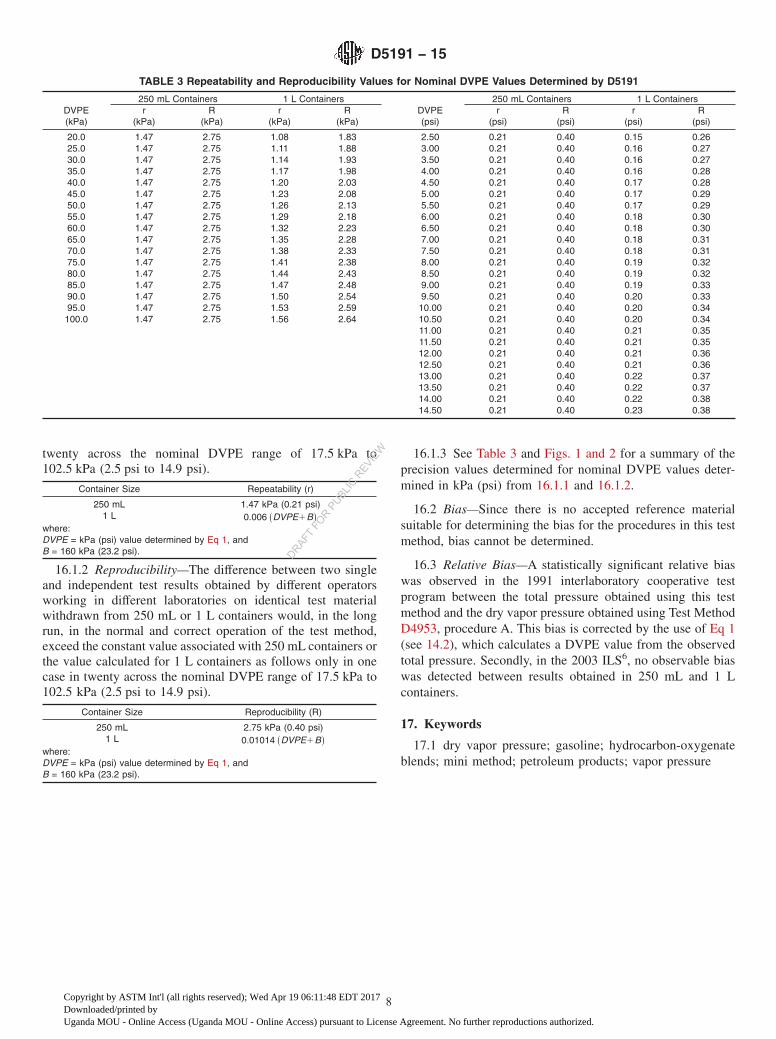
16.1.3 See Table 3 and Figs. 1 and 2 for a summary of theprecision values determined for nominal DVPE values deter-mined in kPa (psi) from 16.1.1 and 16.1.2.
16.2 Bias—Since there is no accepted reference materialsuitable for determining the bias for the procedures in this testmethod, bias cannot be determined.
16.3 Relative Bias—A statistically significant relative biaswas observed in the 1991 interlaboratory cooperative testprogram between the total pressure obtained using this testmethod and the dry vapor pressure obtained using Test MethodD4953, procedure A. This bias is corrected by the use of Eq 1(see 14.2), which calculates a DVPE value from the observedtotal pressure. Secondly, in the 2003 ILS6, no observable biaswas detected between results obtained in 250 mL and 1 Lcontainers.
17. Keywords
17.1 dry vapor pressure; gasoline; hydrocarbon-oxygenateblends; mini method; petroleum products; vapor pressure
TABLE 3 Repeatability and Reproducibility Values for Nominal DVPE Values Determined by D5191
250 mL Containers 1 L Containers 250 mL Containers 1 L ContainersDVPE(kPa)
r(kPa)
R(kPa)
r(kPa)
R(kPa)
DVPE(psi)
r(psi)
R(psi)
r(psi)
R(psi)
20.0 1.47 2.75 1.08 1.83 2.50 0.21 0.40 0.15 0.2625.0 1.47 2.75 1.11 1.88 3.00 0.21 0.40 0.16 0.2730.0 1.47 2.75 1.14 1.93 3.50 0.21 0.40 0.16 0.2735.0 1.47 2.75 1.17 1.98 4.00 0.21 0.40 0.16 0.2840.0 1.47 2.75 1.20 2.03 4.50 0.21 0.40 0.17 0.2845.0 1.47 2.75 1.23 2.08 5.00 0.21 0.40 0.17 0.2950.0 1.47 2.75 1.26 2.13 5.50 0.21 0.40 0.17 0.2955.0 1.47 2.75 1.29 2.18 6.00 0.21 0.40 0.18 0.3060.0 1.47 2.75 1.32 2.23 6.50 0.21 0.40 0.18 0.3065.0 1.47 2.75 1.35 2.28 7.00 0.21 0.40 0.18 0.3170.0 1.47 2.75 1.38 2.33 7.50 0.21 0.40 0.18 0.3175.0 1.47 2.75 1.41 2.38 8.00 0.21 0.40 0.19 0.3280.0 1.47 2.75 1.44 2.43 8.50 0.21 0.40 0.19 0.3285.0 1.47 2.75 1.47 2.48 9.00 0.21 0.40 0.19 0.3390.0 1.47 2.75 1.50 2.54 9.50 0.21 0.40 0.20 0.3395.0 1.47 2.75 1.53 2.59 10.00 0.21 0.40 0.20 0.34100.0 1.47 2.75 1.56 2.64 10.50 0.21 0.40 0.20 0.34
11.00 0.21 0.40 0.21 0.3511.50 0.21 0.40 0.21 0.3512.00 0.21 0.40 0.21 0.3612.50 0.21 0.40 0.21 0.3613.00 0.21 0.40 0.22 0.3713.50 0.21 0.40 0.22 0.3714.00 0.21 0.40 0.22 0.3814.50 0.21 0.40 0.23 0.38
D5191 − 15
8
Copyright by ASTM Int'l (all rights reserved); Wed Apr 19 06:11:48 EDT 2017Downloaded/printed byUganda MOU - Online Access (Uganda MOU - Online Access) pursuant to License Agreement. No further reproductions authorized.
DRAFT FO
R PUBLIC
REVIE
W
APPENDIXES
(Nonmandatory Information)
X1. INFORMATION RELATING TO THE 2003 INTERLABORATORY STUDY (ILS)6 INVOLVING ANALYSESBY D5191 AND D6378
X1.1 Samples
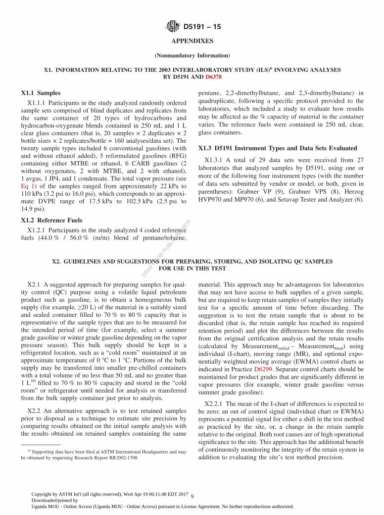
X1.1.1 Participants in the study analyzed randomly orderedsample sets comprised of blind duplicates and replicates fromthe same container of 20 types of hydrocarbons andhydrocarbon-oxygenate blends contained in 250 mL and 1 Lclear glass containers (that is, 20 samples × 2 duplicates × 2bottle sizes × 2 replicates/bottle = 160 analyses/data set). Thetwenty sample types included 6 conventional gasolines (withand without ethanol added), 5 reformulated gasolines (RFG)containing either MTBE or ethanol, 6 CARB gasolines (2without oxygenates, 2 with MTBE, and 2 with ethanol),1 avgas, 1 JP4, and 1 condensate. The total vapor pressure (seeEq 1) of the samples ranged from approximately 22 kPa to110 kPa (3.2 psi to 16.0 psi), which corresponds to an approxi-mate DVPE range of 17.5 kPa to 102.5 kPa (2.5 psi to14.9 psi).
X1.2 Reference Fuels
X1.2.1 Participants in the study analyzed 4 coded referencefuels (44.0 % / 56.0 % (m/m) blend of pentane/toluene,
pentane, 2,2-dimethylbutane, and 2,3-dimethylbutane) inquadruplicate, following a specific protocol provided to thelaboratories, which included a study to evaluate how resultsmay be affected as the % capacity of material in the containervaries. The reference fuels were contained in 250 mL clear,glass containers.
X1.3 D5191 Instrument Types and Data Sets Evaluated
X1.3.1 A total of 29 data sets were received from 27laboratories that analyzed samples by D5191, using one ormore of the following four instrument types (with the numberof data sets submitted by vendor or model, or both, given inparentheses): Grabner VP (9), Grabner VPS (8), HerzogHVP970 and MP970 (6), and Setavap Tester and Analyzer (6).
X2. GUIDELINES AND SUGGESTIONS FOR PREPARING, STORING, AND ISOLATING QC SAMPLESFOR USE IN THIS TEST
X2.1 A suggested approach for preparing samples for qual-ity control (QC) purpose using a volatile liquid petroleumproduct such as gasoline, is to obtain a homogeneous bulksupply (for example, ≥20 L) of the material in a suitably sizedand sealed container filled to 70 % to 80 % capacity that isrepresentative of the sample types that are to be measured forthe intended period of time (for example, select a summergrade gasoline or winter grade gasoline depending on the vaporpressure season). This bulk supply should be kept in arefrigerated location, such as a “cold room” maintained at anapproximate temperature of 0 °C to 1 °C. Portions of the bulksupply may be transferred into smaller pre-chilled containerswith a total volume of no less than 50 mL and no greater than1 L10 filled to 70 % to 80 % capacity and stored in the “coldroom” or refrigerator until needed for analysis or transferredfrom the bulk supply container just prior to analysis.
X2.2 An alternative approach is to test retained samplesprior to disposal as a technique to estimate site precision bycomparing results obtained on the initial sample analysis withthe results obtained on retained samples containing the same
material. This approach may be advantageous for laboratoriesthat may not have access to bulk supplies of a given sample,but are required to keep retain samples of samples they initiallytest for a specific amount of time before discarding. Thesuggestion is to test the retain sample that is about to bediscarded (that is, the retain sample has reached its requiredretention period) and plot the differences between the resultsfrom the original certification analysis and the retain results(calculated by Measurementinitial – Measurementfinal) usingindividual (I-chart), moving range (MR), and optional expo-nentially weighted moving average (EWMA) control charts asindicated in Practice D6299. Separate control charts should bemaintained for product grades that are significantly different invapor pressures (for example, winter grade gasoline versussummer grade gasoline).
X2.2.1 The mean of the I-chart of differences is expected tobe zero; an out of control signal (individual chart or EWMA)represents a potential signal for either a shift in the test methodas practiced by the site, or, a change in the retain samplerelative to the original. Both root causes are of high operationalsignificance to the site. This approach has the additional benefitof continuously monitoring the integrity of the retain system inaddition to evaluating the site’s test method precision.
10 Supporting data have been filed at ASTM International Headquarters and maybe obtained by requesting Research Report RR:D02-1708.
D5191 − 15
9
Copyright by ASTM Int'l (all rights reserved); Wed Apr 19 06:11:48 EDT 2017Downloaded/printed byUganda MOU - Online Access (Uganda MOU - Online Access) pursuant to License Agreement. No further reproductions authorized.
DRAFT FO
R PUBLIC
REVIE
W
SUMMARY OF CHANGES
Subcommittee D02.08 has identified the location of selected changes to this standard since the last issue(D5191 – 13) that may impact the use of this standard. (Approved Oct. 1, 2015.)
(1) Updated subsection 13.1.(2) Updated Table 1.(3) Updated subsections 7.1.1, 11.1, and 11.2.
(4) Added new Table 2 and new footnote 7 (also footnoted inTable 2).
ASTM International takes no position respecting the validity of any patent rights asserted in connection with any item mentionedin this standard. Users of this standard are expressly advised that determination of the validity of any such patent rights, and the riskof infringement of such rights, are entirely their own responsibility.
This standard is subject to revision at any time by the responsible technical committee and must be reviewed every five years andif not revised, either reapproved or withdrawn. Your comments are invited either for revision of this standard or for additional standardsand should be addressed to ASTM International Headquarters. Your comments will receive careful consideration at a meeting of theresponsible technical committee, which you may attend. If you feel that your comments have not received a fair hearing you shouldmake your views known to the ASTM Committee on Standards, at the address shown below.
This standard is copyrighted by ASTM International, 100 Barr Harbor Drive, PO Box C700, West Conshohocken, PA 19428-2959,United States. Individual reprints (single or multiple copies) of this standard may be obtained by contacting ASTM at the aboveaddress or at 610-832-9585 (phone), 610-832-9555 (fax), or [email protected] (e-mail); or through the ASTM website(www.astm.org). Permission rights to photocopy the standard may also be secured from the Copyright Clearance Center, 222Rosewood Drive, Danvers, MA 01923, Tel: (978) 646-2600; http://www.copyright.com/
D5191 − 15
10
Copyright by ASTM Int'l (all rights reserved); Wed Apr 19 06:11:48 EDT 2017Downloaded/printed byUganda MOU - Online Access (Uganda MOU - Online Access) pursuant to License Agreement. No further reproductions authorized.
DRAFT FO
R PUBLIC
REVIE
W