Embed Size (px)
Citation preview
8/3/2019 Fe Analysis of Bird Strikes on Composite and Glass Panels
http://slidepdf.com/reader/full/fe-analysis-of-bird-strikes-on-composite-and-glass-panels 1/89
FINITE ELEMENT ANALYSIS OF BIRD STRIKES ON COMPOSITE AND
GLASS PANELS
KOH CHEE CHUAN
DEPARTMENT OF MECHANICAL ENGINEERING
NATIONAL UNIVERSITY OF SINGAPORE
2005/2006
8/3/2019 Fe Analysis of Bird Strikes on Composite and Glass Panels
http://slidepdf.com/reader/full/fe-analysis-of-bird-strikes-on-composite-and-glass-panels 2/89
FINITE ELEMENT ANALYSIS OF BIRD STRIKES ON COMPOSITE AND
GLASS PANELS
SUBMITTED
BY
KOH CHEE CHUAN
DEPARTMENT OF MECHANICAL ENGINEERING
IN PARTIAL FULFILLMENT OF THE REQUIREMENTS FOR THE DEGREE OF
THE BACHELOR OF ENGINEERING
NATIONAL UNIVERSITY OF SINGAPORE
2005/2006
8/3/2019 Fe Analysis of Bird Strikes on Composite and Glass Panels
http://slidepdf.com/reader/full/fe-analysis-of-bird-strikes-on-composite-and-glass-panels 3/89
Final Year Project Report Abstract
.
ABSTRACT
In this final year project, a 1.82kg homogenous bird model with a simplified geometrical
shape is modeled using the Lagrangian formulation. The reliability of the bird model is
validated by comparing the numerical result with experimental results of a real bird of
similar mass impacting normally at an impact velocity of 116m/s onto a flat rigid panel.
Results are compared in terms of pressure profile, Hugoniot and stagnation pressure at
the centre of the impact and the bird trajectory after the impact. The obtained numerical
results are found to be comparable in terms of pressure profile and the bird trajectory.
Numerical Hugoniot and stagnation pressure are higher by 33% and 20% respectively.
This is attributed to the assumptions made in the formulation of the numerical model.
The modeling of bird strike using the Lagrangian Arbitrary Eulerian and Smooth Particle
Hydrodynamics formulation is then investigated by modeling impact on an elastic
aluminum panel. The verified Lagrangian model serves as a medium for comparison of
the numerical results. The numerical results obtained from the various formulation shows
close conformity implying their appropriateness as alternative in the simulation of bird
strike.
The effect of curvature, of an aircraft windscreen, on the impact response in terms of
effective stress at the center of the impact is also investigated. Analysis is made based on
the obtained numerical results. However experimental results are not available to
substantiate the conclusions made from the numerical results.
i
8/3/2019 Fe Analysis of Bird Strikes on Composite and Glass Panels
http://slidepdf.com/reader/full/fe-analysis-of-bird-strikes-on-composite-and-glass-panels 4/89
Final Year Project Report Acknowledgement
.
ACKNOWLEDGEMENT
The author would like to thank his supervisor, Professor Lee Heow Pueh, for his
guidance and advice rendered to him throughout the course of the final year project. The
author is also grateful for the patience and understandings Professor Lee had given to him.
The author will also like to express his gratitude to Mr Tham Ching Yang for his help in
the use of LS-DYNA and TruegridR, the two software required to execute the project.
The author is thankful for his patience and effort in answering the author’s numerous
queries.
The author would also like to extend his appreciation to all those who have helped him
during the course of the project in one way or another.
ii
8/3/2019 Fe Analysis of Bird Strikes on Composite and Glass Panels
http://slidepdf.com/reader/full/fe-analysis-of-bird-strikes-on-composite-and-glass-panels 5/89
Final Year Project Report Table of Contents
TABLE OF CONTENTS PAGES
ABSTRACT i
ACKNOWLEDGEMENT ii
LIST OF FIGURES v
LIST OF TABLES viii
LIST OF SYMBOLS ix
CHAPTER ONE – INTRODUCTION 1
1.1 Background 1
1.2 Objectives 2
1.3 Scope 2
CHAPTER TWO – LITERATURE REVIEW 4
2.1 Background 4
2.2 Hazard Prevention 5
2.3 Bird Impact Testing 8
CHAPTER THREE – MODELING METHODOLOGY 12
3.1 General Parameters 12
3.2 Bird Model Verification 15
3.3 Evaluation of the Various Finite Element Formulations 18
iii
8/3/2019 Fe Analysis of Bird Strikes on Composite and Glass Panels
http://slidepdf.com/reader/full/fe-analysis-of-bird-strikes-on-composite-and-glass-panels 6/89
Final Year Project Report Table of Contents
3.4 Lagrangian Bird Model 19
3.5 Arbitrary Lagrangian Eulerian Bird Model 21
3.6 Smooth Particles Hydrodynamics Bird Model 24
3.7 Investigation of the Effect of Curvature on Impact Response Due 26
to Bird Strike
CHAPTER FOUR – RESULTS AND DISCUSSIONS 30
4.1 Expected Results from Lagrangian Bird Model 30
4.2 Numerical Results from the Lagrangian Bird Model 32
4.3 Evaluation of the Various Finite Element Formulations 42
4.4 Effect of Curvature on Impact Response 50
CHAPTER FIVE – CONCLUSIONS AND RECOMMENDATIONS 54
5.1 Conclusions and Recommendations 54
REFERENCES
APPENDIX A
APPENDIX B
APPENDIX C
APPENDIX D
APPENDIX E
APPENDIX F
APPENDIX G
APPENDIX H
iv
8/3/2019 Fe Analysis of Bird Strikes on Composite and Glass Panels
http://slidepdf.com/reader/full/fe-analysis-of-bird-strikes-on-composite-and-glass-panels 7/89
Final Year Project Report List of Figures
LIST OF FIGURES PAGES
Figure 2.1: Glaucous Gull, Gull Species, 2.4 – 4lb 6
Figure 2.2: (Left) Mallard, Waterfowl Species, 1.2 – 3.8lb, (Right) 7
Gyrfalcon, Raptor Species, 2.2 – 4.4lb
Figure 2.3: Typical Pressure-Time Plot due to Impact on a Rigid 8
Target from [12]
Figure 2.4: Pressure to Relative Volume Plot for Bird Material with Different 11
Void Volumetric Fractions [11]
Figure 3.1: Geometry of Simplified Bird Model 12
Figure 3.2: Geometry of Rigid Plate 17
Figure 3.3: Lagrangian Bird Model and Rigid Plate after Reflection from the 19
Quarter Model
Figure 3.4: Quarter Model and Corresponding Boundary conditions (Front View) 20
Figure 3.5: ALE Bird Model and Target 22
Figure 3.6: SPH Bird Model and Target 24
Figure 3.7: Cockpit Window for a Transport Aircraft [22] 27
Figure 3.8: Side View of Plate and Introduced Curvature 29
Figure 4.1: Pressure-Time Plot for Bird Impact on Rigid Plate at 116m/s [12] 31
Figure 4.2: Bird Trajectory of a SPH Bird Model after Impact [10] 31
Figure 4.3: Bird Trajectory of a Lagrangian Bird Model after Impact [12] 31
Figure 4.4: Pressure-Time Plot Obtained from the Lagrangian Bird Model 32
Figure 4.5: Bird Trajectory of Lagrangian Bird Model (In Direction Normal 33to the Plate)
Figure 4.6: Energy Plot (Lagrangian Bird Model) 34
v
8/3/2019 Fe Analysis of Bird Strikes on Composite and Glass Panels
http://slidepdf.com/reader/full/fe-analysis-of-bird-strikes-on-composite-and-glass-panels 8/89
Final Year Project Report List of Figures
Figure 4.7: Pressure-Time Plot (Left) and Energy Plot (Right) (Lagrangian 35
Bird Model with Higher Mesh Density)
Figure 4.8: Pressure-Time Plot (Lagrangian Bird Model with Lower Time 36
Step Scale Factor)
Figure 4.9: Pressure-Time Plot (Lagrangian Bird Model with Different Material 38
Model) (Material of Porosity 0.1(Left), Material of Porosity 0.15 (Right)
Figure 4.10: Pressure-Time Plot (Lagrangian Bird Model with Different Material 38Model as Shown in Table 4.3)
Figure 4.11: Effective Stress Plot (A for Lagrangian, B for ALE, C for SPH) 43
Figure 4.12: Resultant Displacement Plot (A for Lagrangian, B for ALE, 43
C for SPH)
Figure 4.13: Pressure Plot (A for Lagrangian, B for ALE, C for SPH) 43
Figure 4.14: Internal Energy Plot (A for Lagrangian, B for ALE, C for SPH) 46
Figure 4.15: Kinetic Energy Plot (A for Lagrangian, B for ALE, C for SPH) 46
Figure 4.16: Total Energy Plot (A for Lagrangian, B for ALE, C for SPH) 47
Figure 4.17: Bird Trajectory of SPH Bird Model (In Direction Normal 47
to the Plate)
Figure 4.18: Bird Trajectory of ALE Bird Model (In Direction Normal 48
to the Plate)
Figure 4.19: Impact Response of Transparency with no Curvature 50
(A for Outer layer, B for Middle Layer, C for Inner Layer)
Figure 4.20: Impact Response of Outer Layer of Transparency (A for Flat 52Target, B for Target with 0.5m Radius of Curvature)
Figure 4.21: Impact Response of Middle Layer of Transparency (A for Flat 52Target, B for Target with 0.5m Radius of Curvature)
Figure 4.22: Impact Response of Inner Layer of Transparency (A for Flat 53Target, B for Target with 0.5m Radius of Curvature)
Figure G1: Effective Stress Plot (Lagrangian Model) G3(A for Coarser Mesh B for Denser Mesh)
vi
8/3/2019 Fe Analysis of Bird Strikes on Composite and Glass Panels
http://slidepdf.com/reader/full/fe-analysis-of-bird-strikes-on-composite-and-glass-panels 9/89
Final Year Project Report List of Figures
Figure G2: Resultant Displacement Plot (Lagrangian Model) G3(A for Coarser Mesh, B for Denser Mesh)
Figure G3: Pressure Plot (Lagrangian Model) G3(A for Coarser Mesh, B for Denser Mesh)
Figure G4: Effective Stress Plot (ALE Model) G4(A for Coarser Mesh B for Denser Mesh)
Figure G5: Resultant Displacement Plot (ALE Model) G4
(A for Coarser Mesh, B for Denser Mesh)
Figure G6: Pressure Plot (ALE Model) G4
(A for Coarser Mesh, B for Denser Mesh)
Figure G7: Effective Stress Plot (SPH Model) G5
(A for Lesser Particles B for More Particles)
Figure G8: Resultant Displacement Plot (SPH Model) G5
(A for Lesser Particles, B for More Particles)
Figure G9: Pressure Plot (SPH Model) G5
(A for Lesser Particles, B for More Particles)
Figure H1: Effect of Curvature on Effective Stress (Outer Layer) H2
(A for plate2, B for plate3, C for Plate4, D for Plate 1, E for Plate 5)
Figure H2: Effect of Curvature on Effective Stress (Middle Layer) H2
(A for plate2, B for plate3, C for Plate4, D for Plate 1, E for Plate 5)
Figure H3: Effect of Curvature on Effective Stress (Inner Layer) H2
(A for plate2, B for plate3, C for Plate4, D for Plate 1, E for Plate 5)
vii
8/3/2019 Fe Analysis of Bird Strikes on Composite and Glass Panels
http://slidepdf.com/reader/full/fe-analysis-of-bird-strikes-on-composite-and-glass-panels 10/89
Final Year Project Report List of Tables
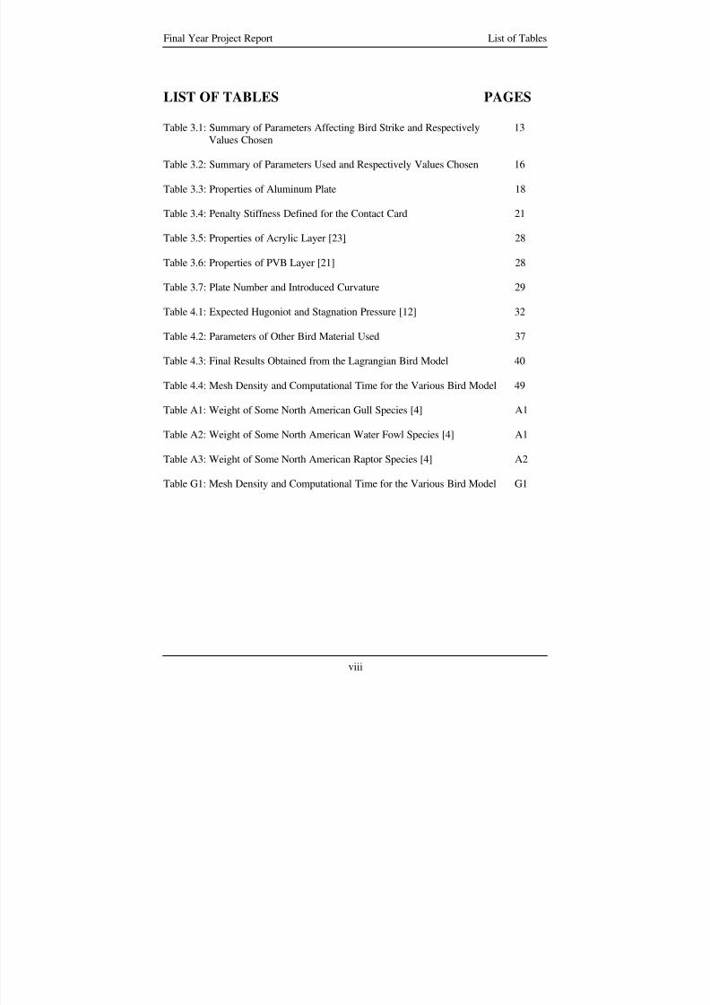
LIST OF TABLES PAGES
Table 3.1: Summary of Parameters Affecting Bird Strike and Respectively 13
Values Chosen
Table 3.2: Summary of Parameters Used and Respectively Values Chosen 16
Table 3.3: Properties of Aluminum Plate 18
Table 3.4: Penalty Stiffness Defined for the Contact Card 21
Table 3.5: Properties of Acrylic Layer [23] 28
Table 3.6: Properties of PVB Layer [21] 28
Table 3.7: Plate Number and Introduced Curvature 29
Table 4.1: Expected Hugoniot and Stagnation Pressure [12] 32
Table 4.2: Parameters of Other Bird Material Used 37
Table 4.3: Final Results Obtained from the Lagrangian Bird Model 40
Table 4.4: Mesh Density and Computational Time for the Various Bird Model 49
Table A1: Weight of Some North American Gull Species [4] A1
Table A2: Weight of Some North American Water Fowl Species [4] A1
Table A3: Weight of Some North American Raptor Species [4] A2
Table G1: Mesh Density and Computational Time for the Various Bird Model G1
viii
8/3/2019 Fe Analysis of Bird Strikes on Composite and Glass Panels
http://slidepdf.com/reader/full/fe-analysis-of-bird-strikes-on-composite-and-glass-panels 11/89
Final Year Project Report List of Symbols
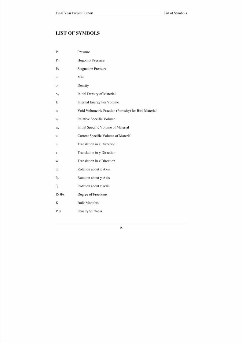
LIST OF SYMBOLS
P Pressure
PH Hugoniot Pressure
PS Stagnation Pressure
μ Miu
ρ Density
ρo Initial Density of Material
E Internal Energy Per Volume
α Void Volumetric Fraction (Porosity) for Bird Material
υr Relative Specific Volume
υo Initial Specific Volume of Material
υ Current Specific Volume of Material
u Translation in x Direction
v Translation in y Direction
w Translation in z Direction
θx Rotation about x Axis
θy Rotation about y Axis
θz Rotation about z Axis
DOFs Degree of Freedoms
K Bulk Modulus
P.S Penalty Stiffness
ix
8/3/2019 Fe Analysis of Bird Strikes on Composite and Glass Panels
http://slidepdf.com/reader/full/fe-analysis-of-bird-strikes-on-composite-and-glass-panels 12/89
Final Year Project Report List of Symbols
E Young’s Modulus
W Kernel Function
m Mass
x Position of SPH Particle
x
8/3/2019 Fe Analysis of Bird Strikes on Composite and Glass Panels
http://slidepdf.com/reader/full/fe-analysis-of-bird-strikes-on-composite-and-glass-panels 13/89
Final Year Project Report Chapter 1 - Introduction
CHAPTER ONE - INTRODUCTION
1.1 BACKGROUND
Bird strikes have been a concern to both civil and military aircrafts. Since 1988, such
incidents have claimed the life of over 195 people [1]. In United States alone, more than
50,000 incidents of bird strikes were reported between 1990 and 2003.
The front facing components of an aircraft which include the nacelles, windshield, wind
leading edge, compressor blade, etc are often most susceptible to such strikes. It is
therefore critical to ensure that the different structural parts are able to withstand such
high velocity impact or at least guarantee the safe landing of the aircraft after the strike.
Certification standards, which include verifying the structural integrity of airframes and
engines, are established by U.S. Federal Aviation administration (FAA) and European
Joint Aviation Authority (JAA) [2]. These empirical verifications, which result in the
damage of prototypes and the biological hazard of using real birds, can be costly and time
consuming. The use of computer simulation to simulate the bird impact on new structural
components serves as a powerful tool for the development of new components by
minimizing the number of empirical testings. It allows the impact response of different
structural and material parameters to be studied before the actual fabrication of the
prototypes, thus reducing time and cost incurred in empirical testing.
1
8/3/2019 Fe Analysis of Bird Strikes on Composite and Glass Panels
http://slidepdf.com/reader/full/fe-analysis-of-bird-strikes-on-composite-and-glass-panels 14/89
Final Year Project Report Chapter 1 - Introduction
1.2 OBJECTIVES
The objective of the final year project includes
1) Obtaining a realistic finite element bird model with the help of scattered reported
studies.
2) Investigating the modeling of bird strike using 3 different formulations namely,
Lagrangian, Arbitrary Lagrangian Eulerian (ALE) and Smooth Particle
Hydrodynamics (SPH) formulation.
3) Investigate what effect curvature, of an aircraft windscreen, has on the impact
response due to bird strike.
1.3 SCOPE
In this final year project, the finite element simulation was performed using LS-DYNA.
A 1.82 kg, homogenous bird model with a simplified geometrical shape was modeled.
The reliability of the bird parameters was validated by simulating collision of the
Lagrangian bird model at 90o onto a flat rigid panel at an impact velocity of 116m/s and
comparing with reported experimental data. Parameters used for the assessment of the
validity of the bird model include the pressure profile at the centre of the impact as well
as the bird trajectory after the impact.
2
8/3/2019 Fe Analysis of Bird Strikes on Composite and Glass Panels
http://slidepdf.com/reader/full/fe-analysis-of-bird-strikes-on-composite-and-glass-panels 15/89
Final Year Project Report Chapter 1 - Introduction
Evaluation of the 3 different finite element formulations, namely Lagrangian, ALE and
SPH in the analysis of bird strike was made by simulating impact of the bird models on
an elastic aluminum flat panel. The numerical results chosen for comparison include the
plot of effective stress, resultant displacement and pressure at the centre of the aluminum
plate. Other aspects that are compared include the bird trajectory after the impact, the
ease of modeling and the computational time required.
Finally the effect of curvature, of an aircraft transparency, on the impact response was
investigated. The study focuses on relative comparison of the effect of curvature instead
of the actual impact response due to bird strike.
.
3
8/3/2019 Fe Analysis of Bird Strikes on Composite and Glass Panels
http://slidepdf.com/reader/full/fe-analysis-of-bird-strikes-on-composite-and-glass-panels 16/89
Final Year Project Report Chapter 2 – Literature Review
CHAPTER TWO – LITERATURE REVIEW
2.1 BACKGROUND
The studies of bird strikes can generally be classified into 2 categories namely hazard
prevention and bird impact testing.
Hazard prevention involves collecting data from cases of bird strikes on aircraft and
implementing measures to prevent them through the better understanding of the nature of
strikes. This includes knowing the type of birds, the location, time of the day, season of
the year, etc whereby the strike occurs.
Although measures have been implemented to prevent bird strikes from occurring, it is
impossible to prevent them totally. It is therefore important to ensure that impact
response on the aircraft are fully understood so as to give assurance to the pilot,
passenger, etc in cases where strikes occur. This is done through bird impact testing.
Bird impact testing consists of empirical studies as well as numerical studies. Through
bird impact testing, new engines and airframes are subjected to simulated and actual bird
strikes. Certification of new aircraft parts are usually done empirically. These testing can
be expensive and time consuming hence preliminary studies are usually done by
numerical simulation before actual empirical testings.
4
8/3/2019 Fe Analysis of Bird Strikes on Composite and Glass Panels
http://slidepdf.com/reader/full/fe-analysis-of-bird-strikes-on-composite-and-glass-panels 17/89
Final Year Project Report Chapter 2 – Literature Review
2.2 HAZARD PREVENTION
Collision between aircraft and bird has been a concern because they threaten the safety of
the people on board the aircraft, results in costly repairs and in the case of commercial
aircraft, a loss in revenue. It is a hazard that threatens to weaken the public confidences
towards the aviation industries. International committees such as the International bird
strike committee, the U.S and Italian bird strike committee, etc [3], have been formed to
counter the threat posed by bird strikes, to better understand the nature of strikes and to
implement measures to prevent such strikes.
Since 1988, over 195 people have been killed world-wide as a result of bird strikes [3].
Bird strikes are not rare cases as most people professed. In the United States alone,
52,493 strikes have been reported from 1990 to 2003. Within this 14 years period,
244,510 hours of aircraft down time and $163.51 million were loss. Analysis of strike
reports has shown that the number of reported strikes constitutes only about 20% of the
total number that truly occur which means that the amount of monetary losses can be
much more than what is actually estimated [3 - 4]. Bird strike is therefore a much more
serious problem than what most people perceived especially when the numbers of aircraft
are increasing every year and becoming faster and quieter.
Generally, the number of reported strike decrease with altitude. Jetliners normally cruise
at about 35,000 feet (10000m) at speeds over 500 miles per hour (224 m/s). They usually
take off and land at a speed of up to 235 miles per hour (105 m/s) [6]. Reported studies [4
5
8/3/2019 Fe Analysis of Bird Strikes on Composite and Glass Panels
http://slidepdf.com/reader/full/fe-analysis-of-bird-strikes-on-composite-and-glass-panels 18/89
Final Year Project Report Chapter 2 – Literature Review
- 5] show that it is near the airport where aircraft are most vulnerable to bird strikes. Birds
are attracted to airport due to the presence of shelter, feeding, drinking and bathing areas.
In United States, 92% of the strikes occur at below 3000 feet (920m) and a total of 97%
of the reported strikes occur during the taking off and landing phase of the aircraft [4].
Due to the higher proportion of strikes at take off and landing, the impact response on
aircraft components, windshield, engine compressor, etc, at an impact speed of around
105m/s is therefore much studied experimentally and numerically.
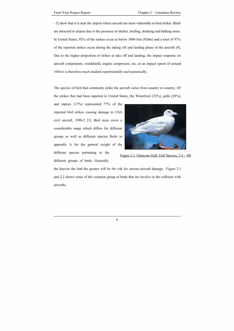
Figure 2.1: Glaucous Gull, Gull Species, 2.4 – 4lb
The species of bird that commonly strike the aircraft varies from country to country. Of
the strikes that had been reported in United States, the Waterfowl (32%), gulls (28%),
and raptors (17%) represented 77% of the
reported bird strikes causing damage to USA
civil aircraft, 1990-2 [3]. Bird sizes cover a
considerable range which differs for different
groups as well as different species Refer to
appendix A for the general weight of the
different species pertaining to the
different groups of birds. Generally,
the heavier the bird the greater will be the risk for serious aircraft damage. Figure 2.1
and 2.2 shows some of the common group of birds that are involve in the collision with
aircrafts.
6
8/3/2019 Fe Analysis of Bird Strikes on Composite and Glass Panels
http://slidepdf.com/reader/full/fe-analysis-of-bird-strikes-on-composite-and-glass-panels 19/89
Final Year Project Report Chapter 2 – Literature Review
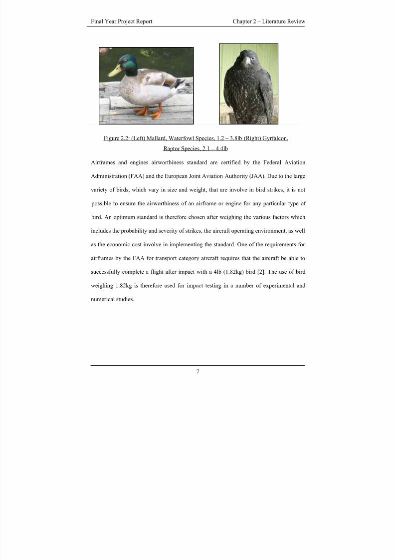
Figure 2.2: (Left) Mallard, Waterfowl Species, 1.2 – 3.8lb (Right) Gyrfalcon,
Raptor Species, 2.1 – 4.4lb
Airframes and engines airworthiness standard are certified by the Federal Aviation
Administration (FAA) and the European Joint Aviation Authority (JAA). Due to the large
variety of birds, which vary in size and weight, that are involve in bird strikes, it is not
possible to ensure the airworthiness of an airframe or engine for any particular type of
bird. An optimum standard is therefore chosen after weighing the various factors which
includes the probability and severity of strikes, the aircraft operating environment, as well
as the economic cost involve in implementing the standard. One of the requirements for
airframes by the FAA for transport category aircraft requires that the aircraft be able to
successfully complete a flight after impact with a 4lb (1.82kg) bird [2]. The use of bird
weighing 1.82kg is therefore used for impact testing in a number of experimental and
numerical studies.
7
8/3/2019 Fe Analysis of Bird Strikes on Composite and Glass Panels
http://slidepdf.com/reader/full/fe-analysis-of-bird-strikes-on-composite-and-glass-panels 20/89
Final Year Project Report Chapter 2 – Literature Review
2.3 BIRD IMPACT TESTING
Similar to bird strike certification process, experimental studies of bird strike are usually
conducted by firing euthanized birds, usually chicken carcass, from gas cannon onto a
target structure at designated speed. However unlike in certification test, experimental
studies tested with alternative material such as gelatin, as substitute for real bird. The
similarity in spatial and temporally pressure distribution on a rigid target from impact by
a real bird and artificial bird of gelatin material suggest that gelatin behaves in a similar
manner to real bird during impact [13 - 15]. High speed firms are used to monitor the
deformation of the target and the bird trajectory at different phase of the impact. Pressure
distribution and deformation on the target due to the impact are measured by mounting of
suitable pressure transducer and strain gauges on the target.
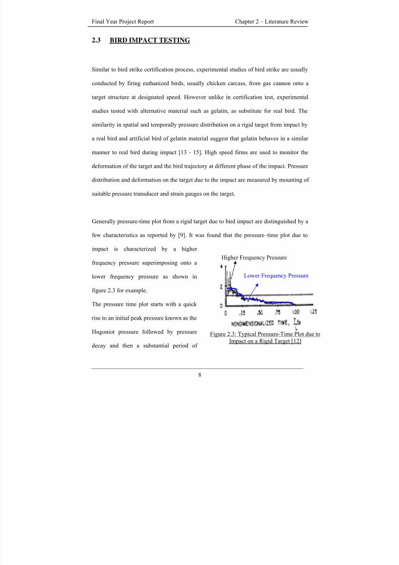
Generally pressure-time plot from a rigid target due to bird impact are distinguished by a
few characteristics as reported by [9]. It was found that the pressure–time plot due to
impact is characterized by a higher
frequency pressure superimposing onto a
lower frequency pressure as shown in
figure 2.3 for example.
The pressure time plot starts with a quick
rise to an initial peak pressure known as the
Hugoniot pressure followed by pressure
decay and then a substantial period of
8
Higher Frequency Pressure
Lower Frequency Pressure
Figure 2.3: Typical Pressure-Time Plot due toImpact on a Rigid Target [12]
8/3/2019 Fe Analysis of Bird Strikes on Composite and Glass Panels
http://slidepdf.com/reader/full/fe-analysis-of-bird-strikes-on-composite-and-glass-panels 21/89
Final Year Project Report Chapter 2 – Literature Review
steady state pressure known as the stagnation pressure. The amplitude of the pressure
falls with increasing radial distance from the centre of impact. Various reported
numerical studies of bird strike have documented the use of bird impact on rigid targets
to validate the parameters of their finite element bird model. They obtain pressure time
plot of comparable characteristics as discussed earlier [10 – 12].
Numerical simulation of bird strikes can be accomplished by a number of commerically
available finite element software which include, PAM-SHOCK [7], LS-DYNA [8], etc.
Before the Arbitrary Lagrange Eulerian (ALE), and the Smooth Particle Hydrodynamics
(SPH) algorthigm are available in commercial finite element software, Lagrangian bird
model had been an established method in the computational simulation of bird strike.
However stability problem associacted with the Lagrangian bird model had been reported
in a number of studies [11 - 12]. Large element distortions in the model of the bird
ultimately leads to numerical errors. To tackle the problem, Airoldi and Cacchione [11]
adopted a numerical strategy which removed the hydrodynamic material response in
zones where numerical errors occured. In recent years, alternative numerical methods
such as the ALE, and the SPH method had been explored to address the stability problem
posed by the Lagrangian method and to better model the bird trajectory after impact. So
far, no stability problem had been reported for numerical studies using ALE and SPH
formulation.
Lagrand et a.l [12] modelled bird impact onto rigid targets using both the Lagrangian and
ALE formulation in Radioss [17]. Results of the ALE model were found to be close to
9
8/3/2019 Fe Analysis of Bird Strikes on Composite and Glass Panels
http://slidepdf.com/reader/full/fe-analysis-of-bird-strikes-on-composite-and-glass-panels 22/89
Final Year Project Report Chapter 2 – Literature Review
Lagrangian ones in terms of local pressure and global load. The simulation time is also
found to be lower for the ALE formulation compared to the Lagrarangian model.
Hannsen [16] used the ALE formulation to simulate bird strike on foam-based sandwich
panels. The bird was modelled using ALE formulation while the sandwich panel
modelled using a Lagrangian approach. Simulated results were compared with
experimental ones in terms of strain and deformation behaviour of the sandwich panel.
The results were found to compare well for the first mili-seconds of the event.
Other authors [10][13 - 14] used SPH method to model the bird, in which the finite
element mesh is replaced by interacting particles. Alastair et al. [10] managed to show
for an impact on a rigid target, a good agreement in the pressure pulse data between
experimental and numerical result could be obtained. McCallum and Constantinou [13]
on the other hand showed a good general agreement between ALE and SPH formulation
for impact on an aluminum deformable plate. In [14], the SPH model was used in an
impact on an aircraft wing leading edge structure. The SPH bird model was able to
capture the breakup of the bird into debirs particle after its collision with the wing leading
edge structure, something that was difficult to accomplish using the Lagrangian method.
The shape of the bird is usually represented as a cylinder with two hemispherical ends as
in most instances; such simple geometry represents the torso of the bird [10 - 14]. Other
shapes that had been experimented before include cylindrical [11] and spherical shape.
Other than the simplified models, [13] modeled a multi-material bird taking the influence
of head and neck during impact for larger birds into consideration.
10
8/3/2019 Fe Analysis of Bird Strikes on Composite and Glass Panels
http://slidepdf.com/reader/full/fe-analysis-of-bird-strikes-on-composite-and-glass-panels 23/89
Final Year Project Report Chapter 2 – Literature Review
Due to the rapid deceleration at the point of impact, the material response of the bird
models can be treated as a fluid as the yield stress of the bird material is greatly exceeded
on impact. The bird material had been characterized as a viscous hydrodynamic fluid in
[12][16]. Considering that the structure of real birds usually consists of some internal
cavities such as lungs, some authors had taken the effect of porosity into consideration in
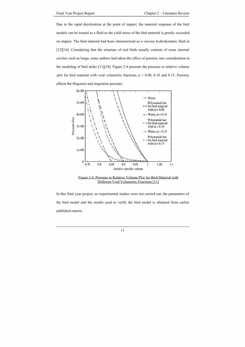
the modeling of bird strike [11][18]. Figure 2.4 presents the pressure to relative volume
plot for bird material with void volumetric fractions, α = 0.00, 0.10 and 0.15. Porosity
affects the Hugoniot and stagnation pressure.
Figure 2.4: Pressure to Relative Volume Plot for Bird Material withDifferent Void Volumetric Fractions [11]
In this final year project, as experimental studies were not carried out, the parameters of
the bird model and the results used to verify the bird model is obtained from earlier
published reports.
11
8/3/2019 Fe Analysis of Bird Strikes on Composite and Glass Panels
http://slidepdf.com/reader/full/fe-analysis-of-bird-strikes-on-composite-and-glass-panels 24/89
Final Year Project Report Chapter 3 – Modeling Methodology
CHAPTER THREE – MODELING METHODOLOGY
3.1 GENERAL PARAMETERS
The finite element analysis of the bird strike is performed using LS-DYNA whereby its
main solution methodology is based on explicit time integration. Explicit methods are
more efficient compared to implicit method for fast phenomenon such as impact [19].
The keyword format is used for the input deck. The finite element mesh of the bird and
the target is generated using TrueGridR
[20]. The parameters discussed in this section
apply to all 3 numerical formulations investigated, namely Lagrangian, ALE and SPH.
The extent of damage that results from bird impact is governed by several parameters.
Some of the more important parameters together with the respective assumptions made or
values chosen for this final year project are summarized in table 3.1. The reasons for
choosing the various parameters are discussed subsequently. It should be noted however
that the choice of the parameters is dependent on the availability of experimental results
with similar bird parameters to compare against.
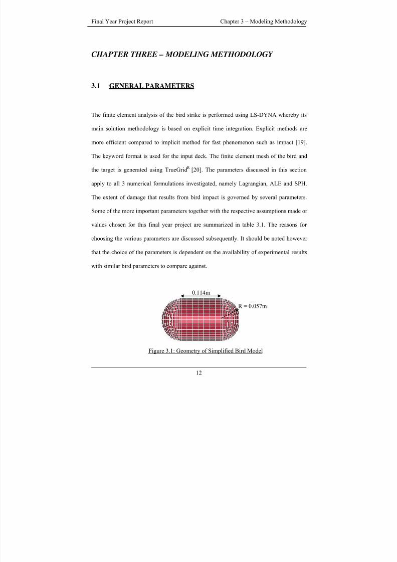
R = 0.057m
0.114m
Figure 3.1: Geometry of Simplified Bird Model
12
8/3/2019 Fe Analysis of Bird Strikes on Composite and Glass Panels
http://slidepdf.com/reader/full/fe-analysis-of-bird-strikes-on-composite-and-glass-panels 25/89
Final Year Project Report Chapter 3 – Modeling Methodology
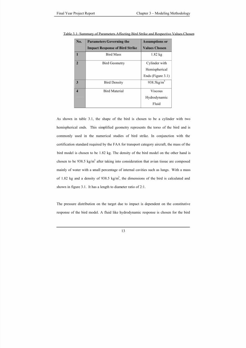
Table 3.1: Summary of Parameters Affecting Bird Strike and Respective Values Chosen
No. Parameters Governing the
Impact Response of Bird Strike
Assumptions or
Values Chosen
1 Bird Mass 1.82 kg
2 Bird Geometry Cylinder with
Hemispherical
Ends (Figure 3.1)
3 Bird Density 938.5kg/m3
4 Bird Material Viscous
Hydrodynamic
Fluid
As shown in table 3.1, the shape of the bird is chosen to be a cylinder with two
hemispherical ends. This simplified geometry represents the torso of the bird and is
commonly used in the numerical studies of bird strike. In conjunction with the
certification standard required by the FAA for transport category aircraft, the mass of the
bird model is chosen to be 1.82 kg. The density of the bird model on the other hand is
chosen to be 938.5 kg/m3
after taking into consideration that avian tissue are composed
mainly of water with a small percentage of internal cavities such as lungs. With a mass
of 1.82 kg and a density of 938.5 kg/m3, the dimensions of the bird is calculated and
shown in figure 3.1. It has a length to diameter ratio of 2:1.
The pressure distribution on the target due to impact is dependent on the constitutive
response of the bird model. A fluid like hydrodynamic response is chosen for the bird
13
8/3/2019 Fe Analysis of Bird Strikes on Composite and Glass Panels
http://slidepdf.com/reader/full/fe-analysis-of-bird-strikes-on-composite-and-glass-panels 26/89
Final Year Project Report Chapter 3 – Modeling Methodology
material as it best represents the impact regime due to bird strike. As seen from figure 2.4,
the constitutive response of the hydrodynamic bird model can be represented by a curve
relating the pressure to the relative volume at different stage of the impact. This curve can
be represented by a polynomial equation involving pressure and relative volume. The
fluid like hydrodynamic response of the bird material model is defined by card
*MAT_NULL and equation of state by card *EOS_LINEAR_POLYNOMIAL in LS-
DYNA. *MAT_NULL card can be used to represent fluid like material. In the
*MAT_NULL card, the material identification of the bird model is defined. The density
as well as the viscosity of the fluid representing the bird is also defined in this card. The
null material model must be used with an equation of state that is defined by a separate
card. The card *EOS_LINEAR_POLYNOMIAL is chosen. In this card, the relationship
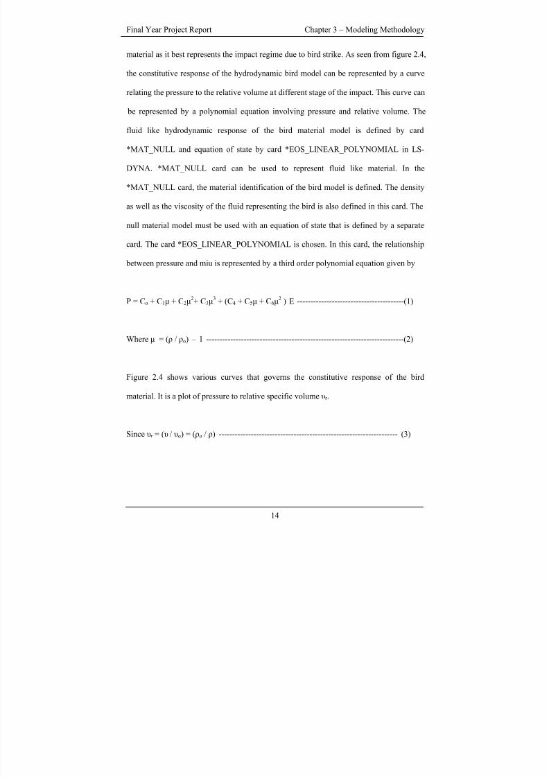
between pressure and miu is represented by a third order polynomial equation given by
P = Co + C1μ + C2μ2+ C3μ
3+ (C4 + C5μ + C6μ
2) E ----------------------------------------(1)
Where μ = (ρ / ρo) – 1 --------------------------------------------------------------------------(2)
Figure 2.4 shows various curves that governs the constitutive response of the bird
material. It is a plot of pressure to relative specific volume υr .
Since υr = ( υ / υo) = (ρo / ρ) ------------------------------------------------------------------- (3)
14
8/3/2019 Fe Analysis of Bird Strikes on Composite and Glass Panels
http://slidepdf.com/reader/full/fe-analysis-of-bird-strikes-on-composite-and-glass-panels 27/89
Final Year Project Report Chapter 3 – Modeling Methodology
It can be shown with some arithmetic that equation 1 and hence
*EOS_LINEAR_POLYNOMIAL can be used to define the curve in figure 2.4 and hence
the constitutive response of the bird model. In this final year project, the bird material is
assumed to be a viscous hydrodynamic fluid as adopted by [12][16] whereby the
coefficients of equation 1 is given by
Cn = 2250 MPa for n = 1 and 0 otherwise --------------------------------------- (4)
Results of the simulation are generated every 0.01ms. This to ensure that sufficient
resolution is given to capture the initial peak of the Hugoniot pressure which occurs
within a time frame of approximately 0.02 ms. A maximum scale factor of 0.9 is set for
the time step to minimize computational time but yet ensure stability.
3.2 BIRD MODEL VERIFICAITON
The reliability of the various parameters discussed earlier is first validated by simulating
bird impact at a velocity of 116m/s on a rigid, flat panel using a Lagrangian bird model.
The experimental results in terms of Hugoniot, stagnation pressure and the pressure
profile at the centre of the rigid targets are obtained from [12] for comparison (Refer to
section 4.1 for more details). A rigid target instead of a deformable one is chosen for the
validation so that the bird parameters can be determined independent of the constitutive
response of the target. A normal impact and a flat panel are chosen so as to simplify the
modeling procedure and to introduce less disparity between numerical and experimental
15
8/3/2019 Fe Analysis of Bird Strikes on Composite and Glass Panels
http://slidepdf.com/reader/full/fe-analysis-of-bird-strikes-on-composite-and-glass-panels 28/89
Final Year Project Report Chapter 3 – Modeling Methodology
conditions. The parameters are summarized in table 3.2. To a certain extent, any major
difference between the numerical and experimental result will then most likely be
attributed to the inaccuracy of the assumed bird parameters.
Table 3.2: Summary of Parameters Used and Respectively Values Chosen
No. Parameters Used Assumptions or
Values Chosen
1 Angle of Impact Normal to
Impacted Surface
2 Impact Velocity 116m/s
3 Shape of Impacted Surface Flat Surface
4 Rigidity of Impacted Surface Rigid /
Deformable
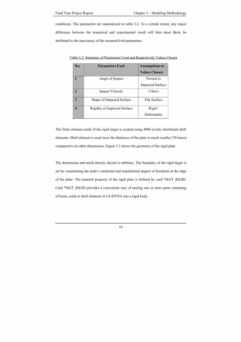
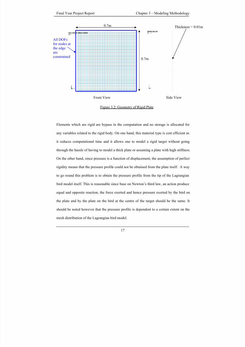
The finite element mesh of the rigid target is created using 4900 evenly distributed shell
elements. Shell element is used since the thickness of the plate is much smaller (70 times)
compared to its other dimensions. Figure 3.2 shows the geometry of the rigid plate.
The dimensions and mesh density chosen is arbitrary. The boundary of the rigid target is
set by constraining the node’s rotational and translational degree of freedoms at the edge
of the plate. The material property of the rigid plate is defined by card *MAT_RIGID.
Card *MAT_RIGID provides a convenient way of turning one or more parts consisting
of beam, solid or shell elements in LS-DYNA into a rigid body.
16
8/3/2019 Fe Analysis of Bird Strikes on Composite and Glass Panels
http://slidepdf.com/reader/full/fe-analysis-of-bird-strikes-on-composite-and-glass-panels 29/89
Final Year Project Report Chapter 3 – Modeling Methodology
0.7m
0.7m
All DOFs
for nodes at
the edgeare
constrained
Thickness = 0.01m
Front View Side View
Figure 3.2: Geometry of Rigid Plate
Elements which are rigid are bypass in the computation and no storage is allocated for
any variables related to the rigid body. On one hand, this material type is cost efficient as
it reduces computational time and it allows one to model a rigid target without going
through the hassle of having to model a thick plate or assuming a plate with high stiffness.
On the other hand, since pressure is a function of displacement, the assumption of perfect
rigidity means that the pressure profile could not be obtained from the plate itself. A way
to go round this problem is to obtain the pressure profile from the tip of the Lagrangian
bird model itself. This is reasonable since base on Newton’s third law, an action produce
equal and opposite reaction, the force exerted and hence pressure exerted by the bird on
the plate and by the plate on the bird at the centre of the target should be the same. It
should be noted however that the pressure profile is dependent to a certain extent on the
mesh distribution of the Lagrangian bird model.
17
8/3/2019 Fe Analysis of Bird Strikes on Composite and Glass Panels
http://slidepdf.com/reader/full/fe-analysis-of-bird-strikes-on-composite-and-glass-panels 30/89
Final Year Project Report Chapter 3 – Modeling Methodology
3.3 EVALUATION OF THE VARIOUS FINITE ELEMENT
FORMULATIONS
After validating the bird parameters as discussed in section 3.1; geometry, constitutive
response, etc, that defines the bird model with the Lagrangian formulation, the bird
parameters can be assumed to be valid and applied to the ALE and SPH bird model.
Table 3.2 summarizes the values of the other parameters adopted. The Lagrangian bird
model can serve as a medium for comparison with the ALE and SPH model. Since the 3
different bird models are created by different formulations, a more reasonable mean of
relating the 3 models would be to obtain the pressure profile from the target instead of the
bird so as to provide a common datum for comparison. For comparison sake, the target is
remodeled to assume the property of a deformable aluminum plate. The geometry and
mesh density remains unchanged. The card *MAT_ELASTIC defines the property of the
deformable aluminum target. The *MAT_ELASTIC card defines isotropic elastic
material and is defined for beam, solid and shell elements. Deformable aluminum plate is
used as information with regards to the property of aluminum is readily available. The
various values used to define property of aluminum are shown in table 3.3.
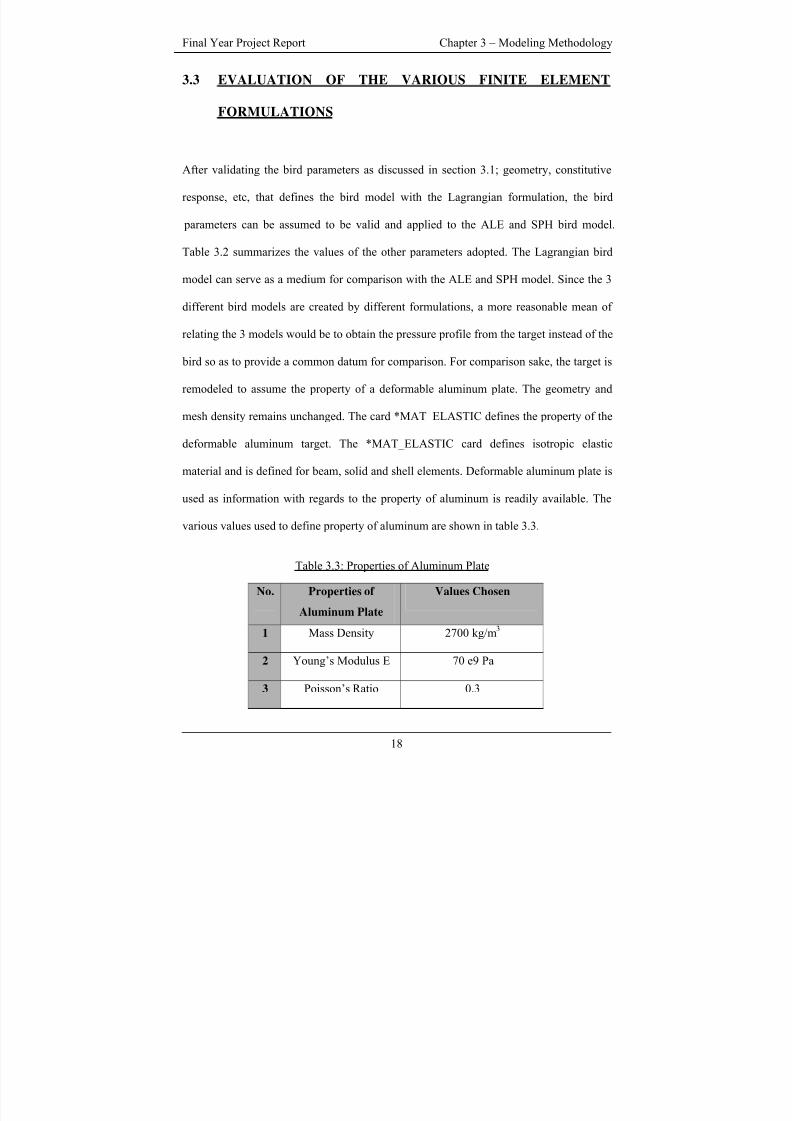
Table 3.3: Properties of Aluminum Plate
No. Properties of
Aluminum Plate
Values Chosen
1 Mass Density 2700 kg/m3
2 Young’s Modulus E 70 e9 Pa
3 Poisson’s Ratio 0.3
18
8/3/2019 Fe Analysis of Bird Strikes on Composite and Glass Panels
http://slidepdf.com/reader/full/fe-analysis-of-bird-strikes-on-composite-and-glass-panels 31/89
Final Year Project Report Chapter 3 – Modeling Methodology
Sections 3.4 to 3.6 discuss the modeling of the bird specific to each of the formulations.
3.4 LAGRANGIAN BIRD MODEL
In the Lagrangian formulation, the material is bounded to the mesh, the mesh followed
the distortion and movement of the material. Due to symmetry, the Lagrangian bird
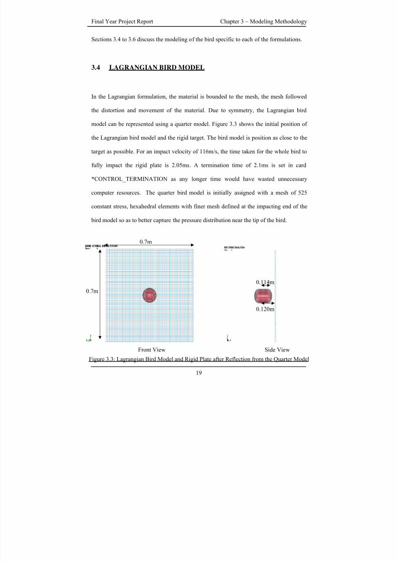
model can be represented using a quarter model. Figure 3.3 shows the initial position of
the Lagrangian bird model and the rigid target. The bird model is position as close to the
target as possible. For an impact velocity of 116m/s, the time taken for the whole bird to
fully impact the rigid plate is 2.05ms. A termination time of 2.1ms is set in card
*CONTROL_TERMINATION as any longer time would have wasted unnecessary
computer resources. The quarter bird model is initially assigned with a mesh of 525
constant stress, hexahedral elements with finer mesh defined at the impacting end of the
bird model so as to better capture the pressure distribution near the tip of the bird.
0.7m
0.114m
0.7m
0.120m
Front View Side View
Figure 3.3: Lagrangian Bird Model and Rigid Plate after Reflection from the Quarter Model
19
8/3/2019 Fe Analysis of Bird Strikes on Composite and Glass Panels
http://slidepdf.com/reader/full/fe-analysis-of-bird-strikes-on-composite-and-glass-panels 32/89
Final Year Project Report Chapter 3 – Modeling Methodology
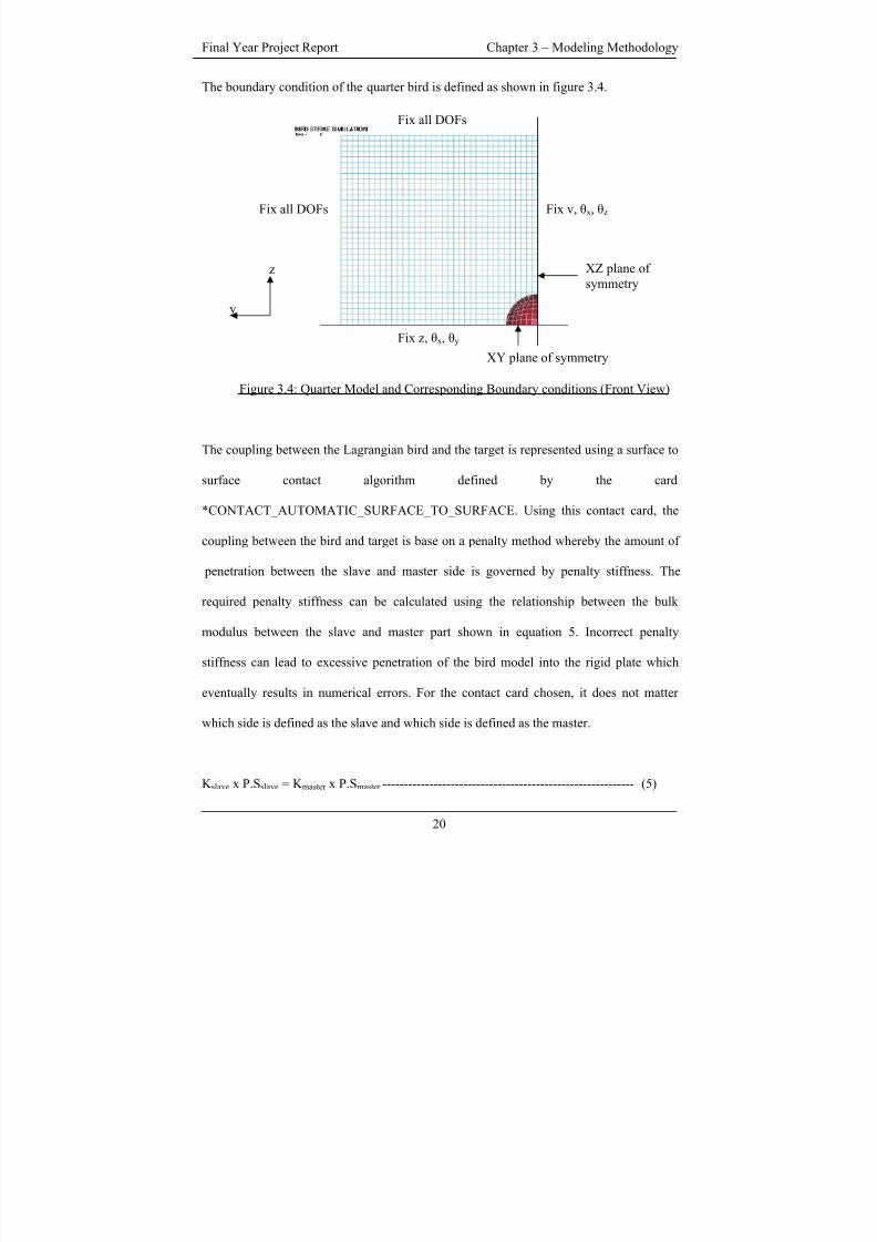
The boundary condition of the quarter bird is defined as shown in figure 3.4.
y
z
Fix v, θx, θz
Fix z, θx, θy
Fix all DOFs
Fix all DOFs
XZ plane of
symmetry
XY plane of symmetry
Figure 3.4: Quarter Model and Corresponding Boundary conditions (Front View)
The coupling between the Lagrangian bird and the target is represented using a surface to
surface contact algorithm defined by the card
*CONTACT_AUTOMATIC_SURFACE_TO_SURFACE. Using this contact card, the
coupling between the bird and target is base on a penalty method whereby the amount of
penetration between the slave and master side is governed by penalty stiffness. The
required penalty stiffness can be calculated using the relationship between the bulk
modulus between the slave and master part shown in equation 5. Incorrect penalty
stiffness can lead to excessive penetration of the bird model into the rigid plate which
eventually results in numerical errors. For the contact card chosen, it does not matter
which side is defined as the slave and which side is defined as the master.
K slave x P.Sslave = K master x P.Smaster ----------------------------------------------------------- (5)
20
8/3/2019 Fe Analysis of Bird Strikes on Composite and Glass Panels
http://slidepdf.com/reader/full/fe-analysis-of-bird-strikes-on-composite-and-glass-panels 33/89
Final Year Project Report Chapter 3 – Modeling Methodology
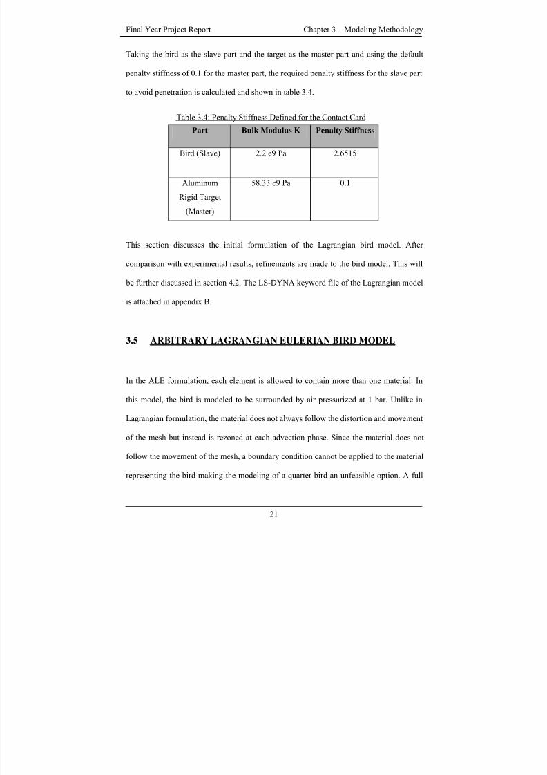
Taking the bird as the slave part and the target as the master part and using the default
penalty stiffness of 0.1 for the master part, the required penalty stiffness for the slave part
to avoid penetration is calculated and shown in table 3.4.
Table 3.4: Penalty Stiffness Defined for the Contact Card
Part Bulk Modulus K Penalty Stiffness
Bird (Slave) 2.2 e9 Pa 2.6515
Aluminum
Rigid Target
(Master)
58.33 e9 Pa 0.1
This section discusses the initial formulation of the Lagrangian bird model. After
comparison with experimental results, refinements are made to the bird model. This will
be further discussed in section 4.2. The LS-DYNA keyword file of the Lagrangian model
is attached in appendix B.
3.5 ARBITRARY LAGRANGIAN EULERIAN BIRD MODEL
In the ALE formulation, each element is allowed to contain more than one material. In
this model, the bird is modeled to be surrounded by air pressurized at 1 bar. Unlike in
Lagrangian formulation, the material does not always follow the distortion and movement
of the mesh but instead is rezoned at each advection phase. Since the material does not
follow the movement of the mesh, a boundary condition cannot be applied to the material
representing the bird making the modeling of a quarter bird an unfeasible option. A full
21
8/3/2019 Fe Analysis of Bird Strikes on Composite and Glass Panels
http://slidepdf.com/reader/full/fe-analysis-of-bird-strikes-on-composite-and-glass-panels 34/89
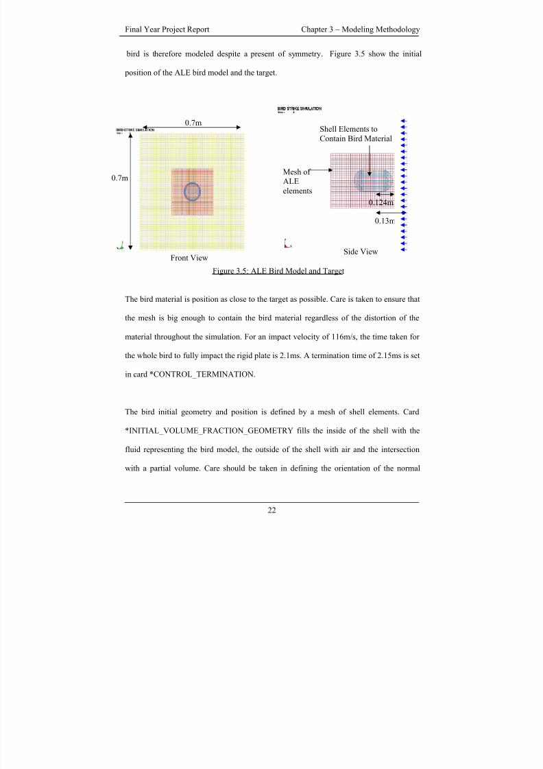
Final Year Project Report Chapter 3 – Modeling Methodology
bird is therefore modeled despite a present of symmetry. Figure 3.5 show the initial
position of the ALE bird model and the target.
Side View
Shell Elements to
Contain Bird Material
0.13m
Mesh of
ALE
elements
0.7m
0.7m
0.124m
Front View
Figure 3.5: ALE Bird Model and Target
The bird material is position as close to the target as possible. Care is taken to ensure that
the mesh is big enough to contain the bird material regardless of the distortion of the
material throughout the simulation. For an impact velocity of 116m/s, the time taken for
the whole bird to fully impact the rigid plate is 2.1ms. A termination time of 2.15ms is set
in card *CONTROL_TERMINATION.
The bird initial geometry and position is defined by a mesh of shell elements. Card
*INITIAL_VOLUME_FRACTION_GEOMETRY fills the inside of the shell with the
fluid representing the bird model, the outside of the shell with air and the intersection
with a partial volume. Care should be taken in defining the orientation of the normal
22
8/3/2019 Fe Analysis of Bird Strikes on Composite and Glass Panels
http://slidepdf.com/reader/full/fe-analysis-of-bird-strikes-on-composite-and-glass-panels 35/89
Final Year Project Report Chapter 3 – Modeling Methodology
vectors belonging to the shell elements as an inconsistent definition with those defined in
the card will result in the spillage of the material outside the intended volume. The
volume fraction card is supposed to be defined together with card
*ALE_MULTI_MATERIAL_GROUP. Card *ALE_MULTI_MATERIAL_GROUP
defines the different groups of material within the ALE elements. The same group of
material will coalesce when they flow into the same element. Two groups of material
namely air surrounding the bird and the fluid representing the bird is defined. The multi-
material card ensures that there is a boundary distinction between the two different
groups of materials throughout the simulation. The bird and the surrounding air is
modeled using an initial mesh of 3528 ALE elements In order to contain the bird material
within the mesh throughout the simulation and to avoid modeling an excessive large
mesh which will increase the computational time, the mesh is allowed to translate and
expand with the help of card *ALE_REFERENCE_SYSTEM_GROUP.
The coupling between the ALE formulated bird model and the Lagrangian formulated
rigid plate is activated by card *CONSTRAINT LANGRANGE IN SOLID. This card
provides the mechanism for coupling interaction between a (slave) Lagrangian geometric
entity to a (master) ALE entity. The normal vector of the Lagrangian formulated plate
should be pointed in the direction of the fluid to be coupled as shown by the blue arrows
in figure 3.5. The ALE elements and the Lagrangian shell elements will not interact
otherwise. Another thing to note about the card *CONSTRAINT LAGRANGE IN
SOLID is the number of coupling points assigned to the surface of each Lagrangian
element. NQUAD in the card defines the number of control points to detect penetration
23
8/3/2019 Fe Analysis of Bird Strikes on Composite and Glass Panels
http://slidepdf.com/reader/full/fe-analysis-of-bird-strikes-on-composite-and-glass-panels 36/89
Final Year Project Report Chapter 3 – Modeling Methodology
between the contact entities. Leakage will occur if there are insufficient control points.
NQUAD is generally 2 to 3 per ALE element. NQUAD is defined depending on the
number of Lagrangian elements spanning each ALE element. The LS-DYNA keyword
file of the ALE model is attached in appendix C.
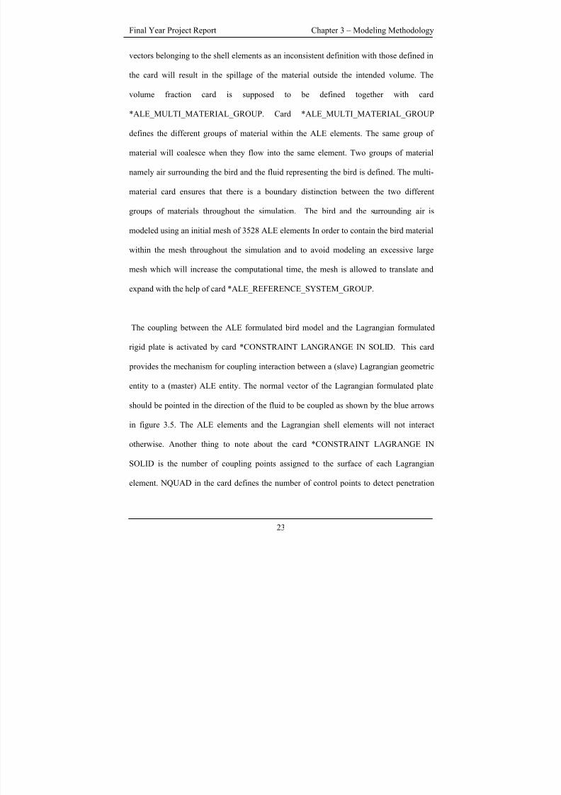
3.6 SMOOTH PARTICLE HYDRODYNAMICS BIRD MODEL
SPH is a mesh free numerical method unlike the Lagrangian and ALE formulation. The
material is represented by a set of discrete particles. TruegridR
cannot generate a gridless
model. To model the SPH bird, a finite element mesh is first generated in TruegridR
and
then manually converted to sets of discrete particles within the input deck. A full SPH
bird is modeled. Figure 3.6 shows the initial position of the SPH bird model and the
target captured from LS-PREPOST.
0.7m
Front View Side View
0.120m
0.114m0.7m
Figure 3.6: SPH Bird Model and Target
24
8/3/2019 Fe Analysis of Bird Strikes on Composite and Glass Panels
http://slidepdf.com/reader/full/fe-analysis-of-bird-strikes-on-composite-and-glass-panels 37/89
Final Year Project Report Chapter 3 – Modeling Methodology
The initial position of the SPH bird model is similar to the Lagrangian bird model except
that the elements are replaced by particles. A termination time of 2.1ms is set in card
*CONTROL_TERMINATION.
For SPH formulation, the property of a particle of interest could be obtained by the
property of its surrounding particles which is governed by the kernel function and the
smoothing length. The property of any particle can be obtained by summing the relevant
properties of other particles which lies within a radius of 2 smoothing length. The
quantity A of any particle i represented by Ai, can be represented by the equation
Ai (r) = ∑ m j (A j/ρ j) W(xi – x j, h) ------------------------------------------------------------(6)
Where xi and x j are the location of particles i and j respectively. m j and ρ j are the mass
and density associated with particle j. W is the kernel function which is a function of the
smoothing length and the position of the relevant particles. The contribution of each
particle to the particle of interest is weighted by the kernel function.
The SPH processor in LS-DYNA uses a variable smoothing length, keeping the same
number of particles in the neighborhood of the particle of interest. The maximum and
minimum value which this smoothing length varies can be defined in card
*SECTION_SPH. Using a variable smoothing length optimize the computation in the
region of interest whereby the smoothing length is decrease for denser region and vice
25
8/3/2019 Fe Analysis of Bird Strikes on Composite and Glass Panels
http://slidepdf.com/reader/full/fe-analysis-of-bird-strikes-on-composite-and-glass-panels 38/89
Final Year Project Report Chapter 3 – Modeling Methodology
versa. For the SPH bird model, the scale factor for the maximum and minimum
smoothing length is set at 0.2 and 2 respectively.
A box is defined in the card *CONTROL_SPH. Particle approximation is computed for
particles within the defined box. Particles that are outside the box are deactivated. This
saves computational time as particles that no longer interact with the structure are
eliminated.
The coupling between the SPH bird model and the target is represented using a node to
surface contact algorithm. Definition of the card is similar to that defined in the surface to
surface contact algorithm of the Lagrangian formulation which requires defining the
slave part, the master part and the penalty stiffness. The nodes should be defined as the
slave while the shell elements the master. The same penalty stiffness is used as in table
3.3. The LS-DYNA keyword file of the SPH model is attached in appendix D.
3.7 INVESTIGATION OF THE EFFECT OF CURVATURE ON
IMPACT RESPONSE DUE TO THE BIRD STRIKE
A simplified finite element model of an aircraft windshield shown in figure 3.7 is
modeled. The objective of modeling the windshield is to investigate what effect curvature,
of an aircraft windshield, has on the impact response due to bird strike.
26
8/3/2019 Fe Analysis of Bird Strikes on Composite and Glass Panels
http://slidepdf.com/reader/full/fe-analysis-of-bird-strikes-on-composite-and-glass-panels 39/89
Final Year Project Report Chapter 3 – Modeling Methodology
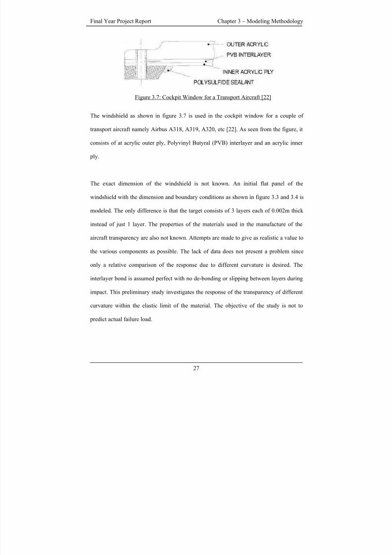
Figure 3.7: Cockpit Window for a Transport Aircraft [22]
The windshield as shown in figure 3.7 is used in the cockpit window for a couple of
transport aircraft namely Airbus A318, A319, A320, etc [22]. As seen from the figure, it
consists of at acrylic outer ply, Polyvinyl Butyral (PVB) interlayer and an acrylic inner
ply.
The exact dimension of the windshield is not known. An initial flat panel of the
windshield with the dimension and boundary conditions as shown in figure 3.3 and 3.4 is
modeled. The only difference is that the target consists of 3 layers each of 0.002m thick
instead of just 1 layer. The properties of the materials used in the manufacture of the
aircraft transparency are also not known. Attempts are made to give as realistic a value to
the various components as possible. The lack of data does not present a problem since
only a relative comparison of the response due to different curvature is desired. The
interlayer bond is assumed perfect with no de-bonding or slipping between layers during
impact. This preliminary study investigates the response of the transparency of different
curvature within the elastic limit of the material. The objective of the study is not to
predict actual failure load.
27
8/3/2019 Fe Analysis of Bird Strikes on Composite and Glass Panels
http://slidepdf.com/reader/full/fe-analysis-of-bird-strikes-on-composite-and-glass-panels 40/89
Final Year Project Report Chapter 3 – Modeling Methodology
The property of the acrylic layers are defined by card *MAT_PLASTIC_KINEMATIC.
Within the card, the parameters defined are summarized in table 3.5.
Table 3.5: Properties of Acrylic Layer [23]
No. Properties of Acrylic Layer Values Chosen
1 Mass Density 1180 kg/m3
2 Young’s Modulus 3.1 GPa
3 Poisson Ratio 0.4
4 Yield Stress 73.5 MPa
5 Tangent Modulus 0
6 Hardening Parameter 0.5
Properties of PVB interlayer is define by card *MAT_VISCOELASTIC. Within the card,
the parameters defined are summarized in table 3.6.
Table 3.6: Properties of PVB Layer [21]
No. Properties of PVB Layer Values Chosen
1 Mass Density 1100 kg/m3
2 Elastic Bulk Modulus 2 GPa
3 Short Time Shear Modulus 1 GPa
4 Long Time Shear Modulus 0.69MPa
5 Decay Constant 12.6 s-1
28
8/3/2019 Fe Analysis of Bird Strikes on Composite and Glass Panels
http://slidepdf.com/reader/full/fe-analysis-of-bird-strikes-on-composite-and-glass-panels 41/89
Final Year Project Report Chapter 3 – Modeling Methodology
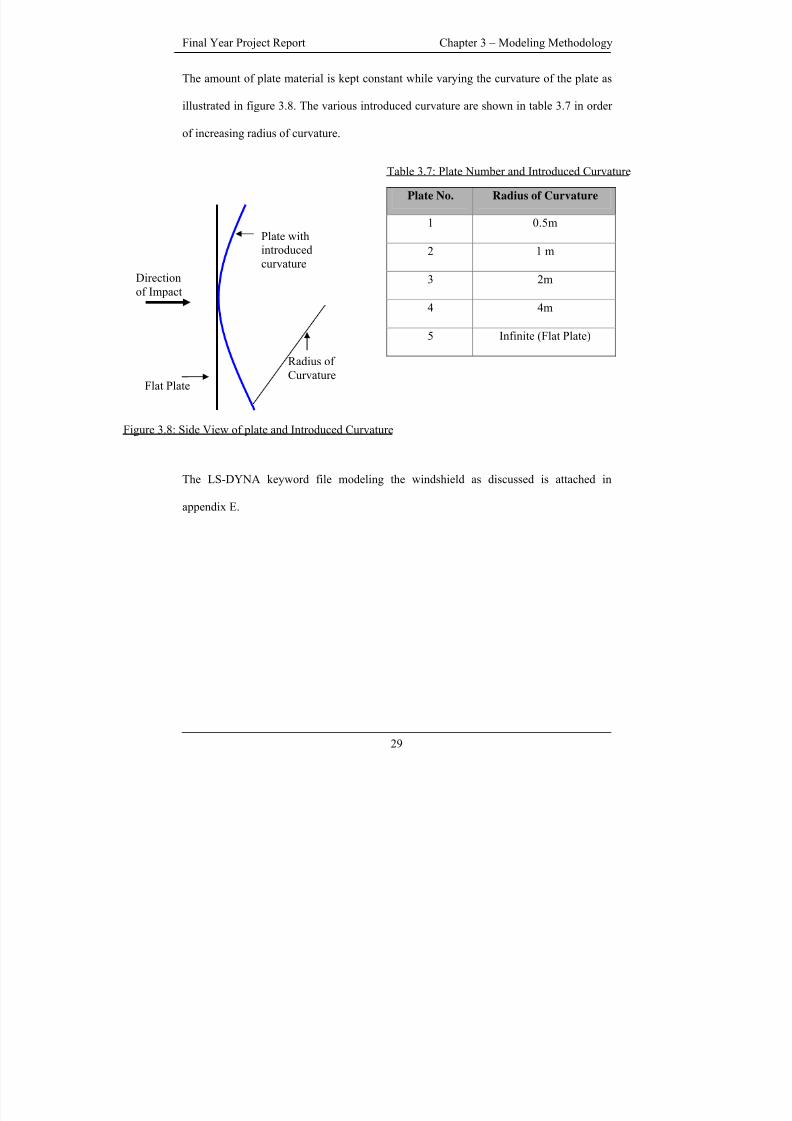
The amount of plate material is kept constant while varying the curvature of the plate as
illustrated in figure 3.8. The various introduced curvature are shown in table 3.7 in order
of increasing radius of curvature.
Plate No. Radius of Curvature
1 0.5m
2 1 m
3 2m
4 4m
5 Infinite (Flat Plate)
Radius of
Curvature
Plate withintroduced
curvature
Flat Plate
Table 3.7: Plate Number and Introduced Curvature
Direction
of Impact
Figure 3.8: Side View of plate and Introduced Curvature
The LS-DYNA keyword file modeling the windshield as discussed is attached in
appendix E.
29
8/3/2019 Fe Analysis of Bird Strikes on Composite and Glass Panels
http://slidepdf.com/reader/full/fe-analysis-of-bird-strikes-on-composite-and-glass-panels 42/89
Final Year Project Report Chapter 4 – Results and Discussions
CHAPTER FOUR – RESULTS AND DISCUSSIONS
4.1 EXPECTED RESULT FROMS THE LAGRANGIAN BIRD
MODEL
The verification of the bird parameters as well as the Lagrangian bird model focus on the
accurate
1) Modeling of pressure profile at the centre of the rigid target during the impact.
2) Representation of Hugoniot pressure at the centre of the rigid target.
3) Representation of Stagnation pressure at the centre of the rigid target.
4) Representation of bird trajectory after the impact.
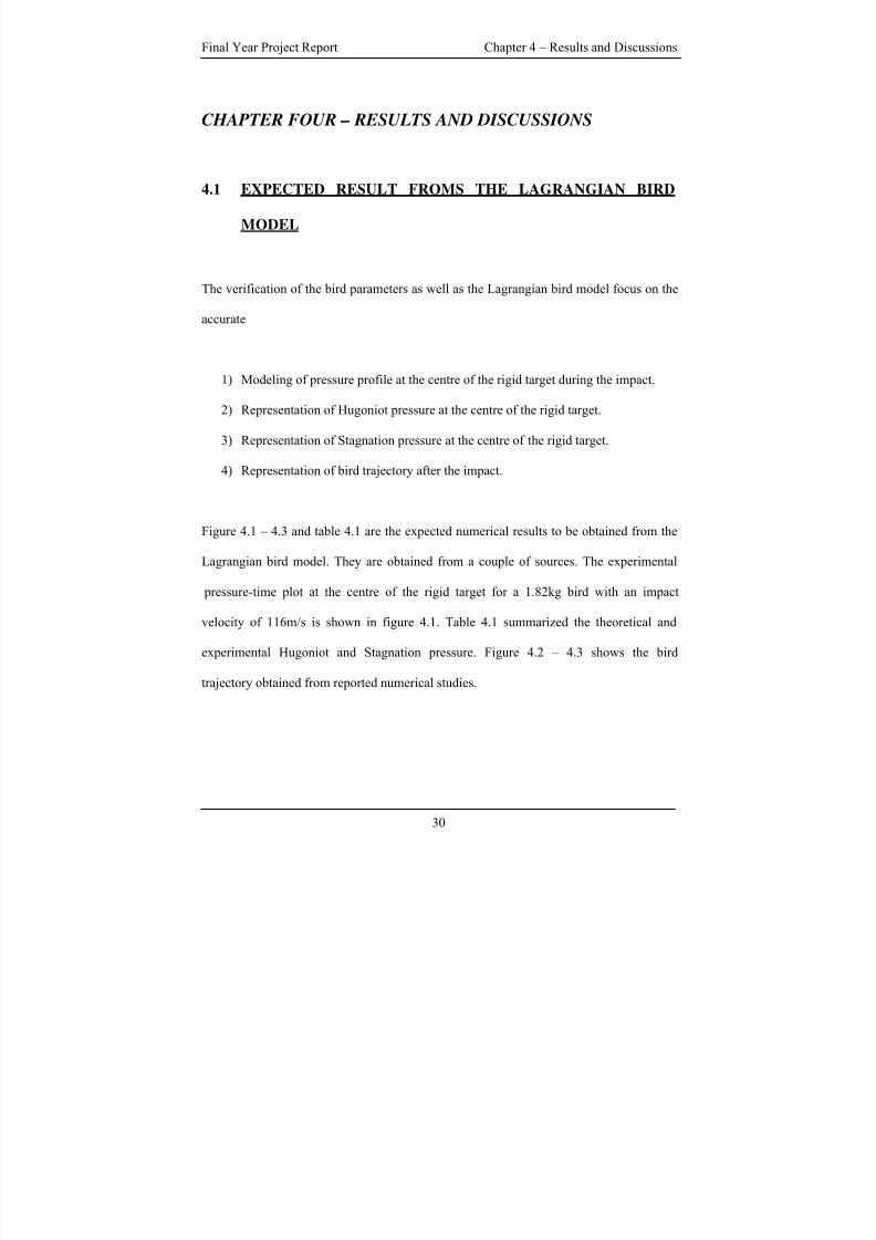
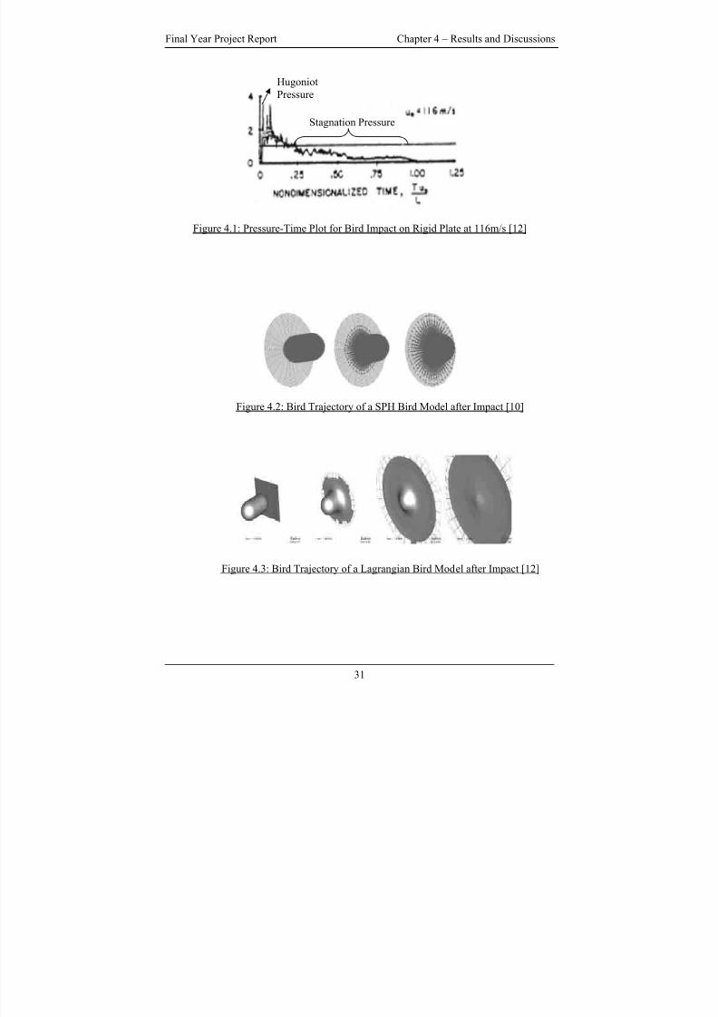
Figure 4.1 – 4.3 and table 4.1 are the expected numerical results to be obtained from the
Lagrangian bird model. They are obtained from a couple of sources. The experimental
pressure-time plot at the centre of the rigid target for a 1.82kg bird with an impact
velocity of 116m/s is shown in figure 4.1. Table 4.1 summarized the theoretical and
experimental Hugoniot and Stagnation pressure. Figure 4.2 – 4.3 shows the bird
trajectory obtained from reported numerical studies.
30
8/3/2019 Fe Analysis of Bird Strikes on Composite and Glass Panels
http://slidepdf.com/reader/full/fe-analysis-of-bird-strikes-on-composite-and-glass-panels 43/89
Final Year Project Report Chapter 4 – Results and Discussions
Hugoniot
Pressure
Stagnation Pressure
Figure 4.1: Pressure-Time Plot for Bird Impact on Rigid Plate at 116m/s [12]
Figure 4.2: Bird Trajectory of a SPH Bird Model after Impact [10]
Figure 4.3: Bird Trajectory of a Lagrangian Bird Model after Impact [12]
31
8/3/2019 Fe Analysis of Bird Strikes on Composite and Glass Panels
http://slidepdf.com/reader/full/fe-analysis-of-bird-strikes-on-composite-and-glass-panels 44/89
Final Year Project Report Chapter 4 – Results and Discussions
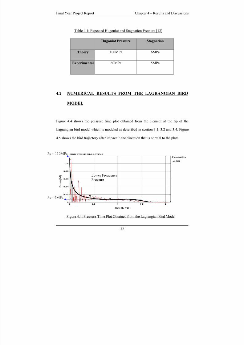
Table 4.1: Expected Hugoniot and Stagnation Pressure [12]
Hugoniot Pressure Stagnation
Theory 100MPa 6MPa
Experimental 60MPa 5MPa
4.2 NUMERICAL RESULTS FROM THE LAGRANGIAN BIRD
MODEL
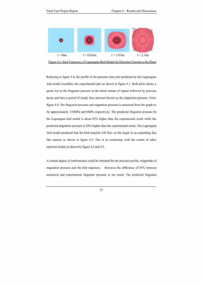
Figure 4.4 shows the pressure time plot obtained from the element at the tip of the
Lagrangian bird model which is modeled as described in section 3.1, 3.2 and 3.4. Figure
4.5 shows the bird trajectory after impact in the direction that is normal to the plate.
PH ≈ 110MPa
Lower Frequency
Pressure
PS ≈ 6MPa
Figure 4.4: Pressure-Time Plot Obtained from the Lagrangian Bird Model
32
8/3/2019 Fe Analysis of Bird Strikes on Composite and Glass Panels
http://slidepdf.com/reader/full/fe-analysis-of-bird-strikes-on-composite-and-glass-panels 45/89
Final Year Project Report Chapter 4 – Results and Discussions
t = 0ms t = 0.63ms t = 1.47ms t = 2.1ms
Figure 4.5: Bird Trajectory of Lagrangian Bird Model (In Direction Normal to the Plate)
Referring to figure 4.4, the profile of the pressure time plot predicted by the Lagrangian
bird model resembles the experimental plot as shown in figure 4.1. Both plots shows a
quick rise to the Hugoniot pressure at the initial instant of impact followed by pressure
decay and then a period of steady flow pressure known as the stagnation pressure. From
figure 4.4, The Hugoniot pressure and stagnation pressure is measured from the graph to
be approximately 110MPa and 6MPa respectively. The predicted Hugoniot pressure by
the Lagrangian bird model is about 85% higher than the experimental result while the
predicted stagnation pressure is 20% higher than the experimental result. The Lagrangian
bird model predicted that the bird material will flow on the target in an expanding disc
like manner as shown in figure 4.5. This is in conformity with the results of other
reported studies as shown by figure 4.2 and 4.3.
A certain degree of conformance could be obtained for the pressure profile, magnitude of
stagnation pressure and the bird trajectory. However the difference of 85% between
numerical and experimental Hugoniot pressure is too much. The predicted Hugoniot
33
8/3/2019 Fe Analysis of Bird Strikes on Composite and Glass Panels
http://slidepdf.com/reader/full/fe-analysis-of-bird-strikes-on-composite-and-glass-panels 46/89
Final Year Project Report Chapter 4 – Results and Discussions
pressure of 110 MPa is even higher than the theoretical Hugoniot pressure of 100 MPa.
Attempts were made to acquire a better conformance between the numerical and
experimental Hugoniot pressure.
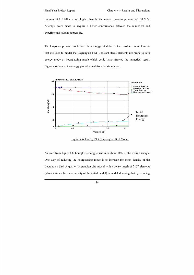
The Hugoniot pressure could have been exaggerated due to the constant stress elements
that are used to model the Lagrangian bird. Constant stress elements are prone to zero
energy mode or hourglassing mode which could have affected the numerical result.
Figure 4.6 showed the energy plot obtained from the simulation.
InitialHourglass
Energy
Figure 4.6: Energy Plot (Lagrangian Bird Model)
As seen from figure 4.6, hourglass energy constitutes about 16% of the overall energy.
One way of reducing the hourglassing mode is to increase the mesh density of the
Lagrangian bird. A quarter Lagrangian bird model with a denser mesh of 2107 elements
(about 4 times the mesh density of the initial model) is modeled hoping that by reducing
34
8/3/2019 Fe Analysis of Bird Strikes on Composite and Glass Panels
http://slidepdf.com/reader/full/fe-analysis-of-bird-strikes-on-composite-and-glass-panels 47/89
Final Year Project Report Chapter 4 – Results and Discussions
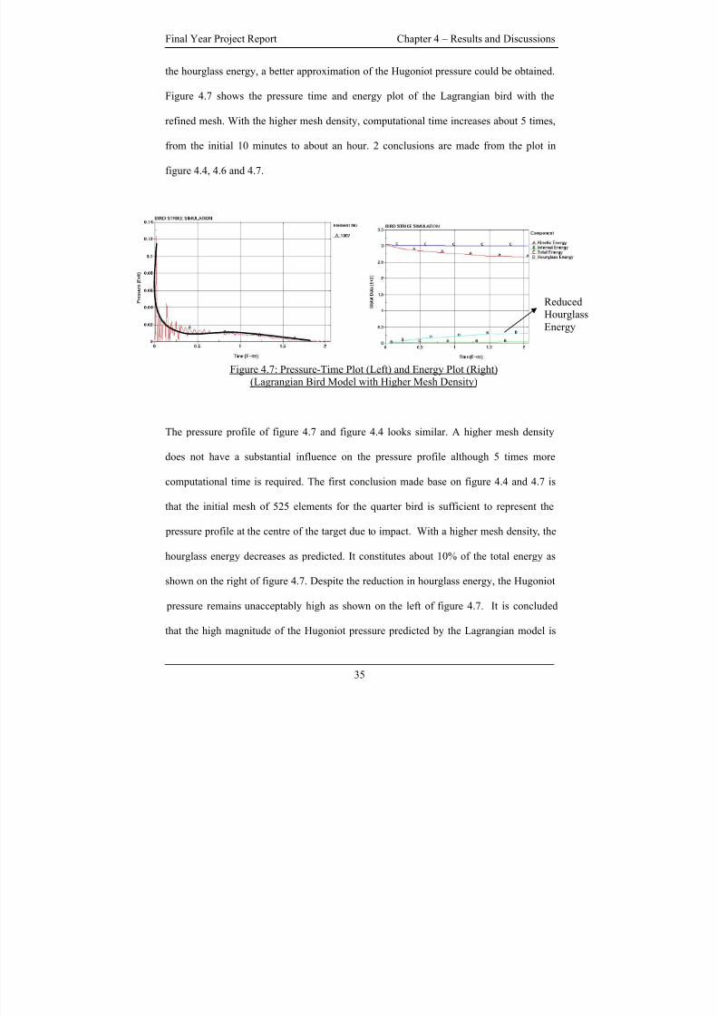
the hourglass energy, a better approximation of the Hugoniot pressure could be obtained.
Figure 4.7 shows the pressure time and energy plot of the Lagrangian bird with the
refined mesh. With the higher mesh density, computational time increases about 5 times,
from the initial 10 minutes to about an hour. 2 conclusions are made from the plot in
figure 4.4, 4.6 and 4.7.
Reduced
Hourglass
Energy
Figure 4.7: Pressure-Time Plot (Left) and Energy Plot (Right)(Lagrangian Bird Model with Higher Mesh Density)
The pressure profile of figure 4.7 and figure 4.4 looks similar. A higher mesh density
does not have a substantial influence on the pressure profile although 5 times more
computational time is required. The first conclusion made base on figure 4.4 and 4.7 is
that the initial mesh of 525 elements for the quarter bird is sufficient to represent the
pressure profile at the centre of the target due to impact. With a higher mesh density, the
hourglass energy decreases as predicted. It constitutes about 10% of the total energy as
shown on the right of figure 4.7. Despite the reduction in hourglass energy, the Hugoniot
pressure remains unacceptably high as shown on the left of figure 4.7. It is concluded
that the high magnitude of the Hugoniot pressure predicted by the Lagrangian model is
35
8/3/2019 Fe Analysis of Bird Strikes on Composite and Glass Panels
http://slidepdf.com/reader/full/fe-analysis-of-bird-strikes-on-composite-and-glass-panels 48/89
Final Year Project Report Chapter 4 – Results and Discussions
not due to the effect of the hourglass energy. In fact this can be inferred intuitively since
the Hugoniot pressure occurs at the beginning of the impact where hourglass energy had
not become significant yet.
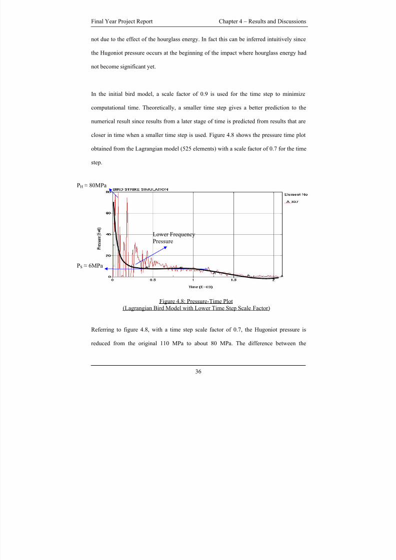
In the initial bird model, a scale factor of 0.9 is used for the time step to minimize
computational time. Theoretically, a smaller time step gives a better prediction to the
numerical result since results from a later stage of time is predicted from results that are
closer in time when a smaller time step is used. Figure 4.8 shows the pressure time plot
obtained from the Lagrangian model (525 elements) with a scale factor of 0.7 for the time
step.
PH ≈ 80MPa
Lower Frequency
Pressure
PS ≈ 6MPa
Figure 4.8: Pressure-Time Plot(Lagrangian Bird Model with Lower Time Step Scale Factor)
Referring to figure 4.8, with a time step scale factor of 0.7, the Hugoniot pressure is
reduced from the original 110 MPa to about 80 MPa. The difference between the
36
8/3/2019 Fe Analysis of Bird Strikes on Composite and Glass Panels
http://slidepdf.com/reader/full/fe-analysis-of-bird-strikes-on-composite-and-glass-panels 49/89
Final Year Project Report Chapter 4 – Results and Discussions
numerical and experimental Hugoniot pressure is approximately 33% compared to the
previous 85%. A better agreement between numerical and experimental results is
obtained with a lower scale factor. The bird trajectory and the energy plot obtained are
similar to figure 4.5 and 4.6.
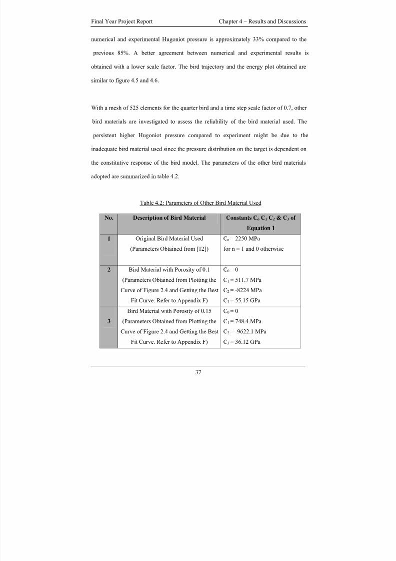
With a mesh of 525 elements for the quarter bird and a time step scale factor of 0.7, other
bird materials are investigated to assess the reliability of the bird material used. The
persistent higher Hugoniot pressure compared to experiment might be due to the
inadequate bird material used since the pressure distribution on the target is dependent on
the constitutive response of the bird model. The parameters of the other bird materials
adopted are summarized in table 4.2.
Table 4.2: Parameters of Other Bird Material Used
No. Description of Bird Material Constants Co C1 C2 & C3 of
Equation 1
1 Original Bird Material Used
(Parameters Obtained from [12])
Cn = 2250 MPa
for n = 1 and 0 otherwise
2 Bird Material with Porosity of 0.1
(Parameters Obtained from Plotting the
Curve of Figure 2.4 and Getting the Best
Fit Curve. Refer to Appendix F)
C0 = 0
C1 = 511.7 MPa
C2 = -8224 MPa
C3 = 55.15 GPa
3
Bird Material with Porosity of 0.15
(Parameters Obtained from Plotting the
Curve of Figure 2.4 and Getting the Best
Fit Curve. Refer to Appendix F)
C0 = 0
C1 = 748.4 MPa
C2 = -9622.1 MPa
C3 = 36.12 GPa
37
8/3/2019 Fe Analysis of Bird Strikes on Composite and Glass Panels
http://slidepdf.com/reader/full/fe-analysis-of-bird-strikes-on-composite-and-glass-panels 50/89
Final Year Project Report Chapter 4 – Results and Discussions
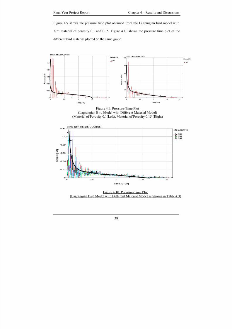
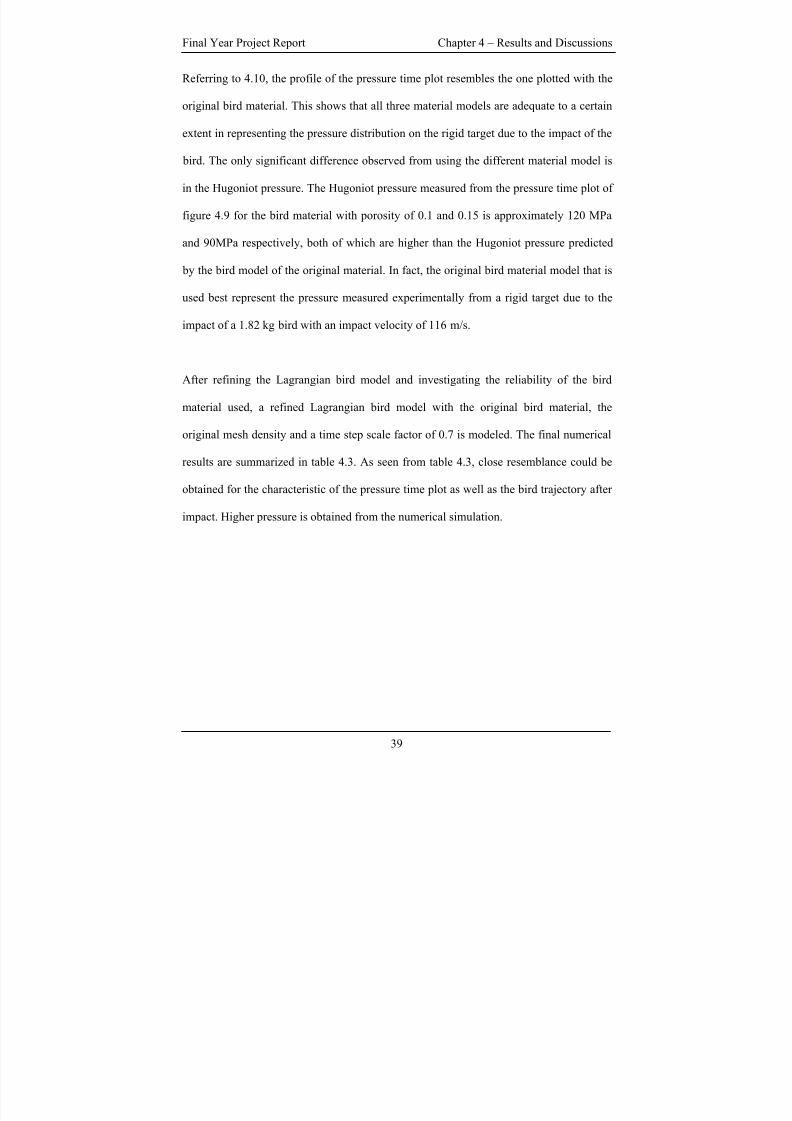
Figure 4.9 shows the pressure time plot obtained from the Lagrangian bird model with
bird material of porosity 0.1 and 0.15. Figure 4.10 shows the pressure time plot of the
different bird material plotted on the same graph.
Figure 4.9: Pressure-Time Plot
(Lagrangian Bird Model with Different Material Model)
(Material of Porosity 0.1(Left), Material of Porosity 0.15 (Right)
Figure 4.10: Pressure-Time Plot(Lagrangian Bird Model with Different Material Model as Shown in Table 4.3)
38
8/3/2019 Fe Analysis of Bird Strikes on Composite and Glass Panels
http://slidepdf.com/reader/full/fe-analysis-of-bird-strikes-on-composite-and-glass-panels 51/89
Final Year Project Report Chapter 4 – Results and Discussions
Referring to 4.10, the profile of the pressure time plot resembles the one plotted with the
original bird material. This shows that all three material models are adequate to a certain
extent in representing the pressure distribution on the rigid target due to the impact of the
bird. The only significant difference observed from using the different material model is
in the Hugoniot pressure. The Hugoniot pressure measured from the pressure time plot of
figure 4.9 for the bird material with porosity of 0.1 and 0.15 is approximately 120 MPa
and 90MPa respectively, both of which are higher than the Hugoniot pressure predicted
by the bird model of the original material. In fact, the original bird material model that is
used best represent the pressure measured experimentally from a rigid target due to the
impact of a 1.82 kg bird with an impact velocity of 116 m/s.
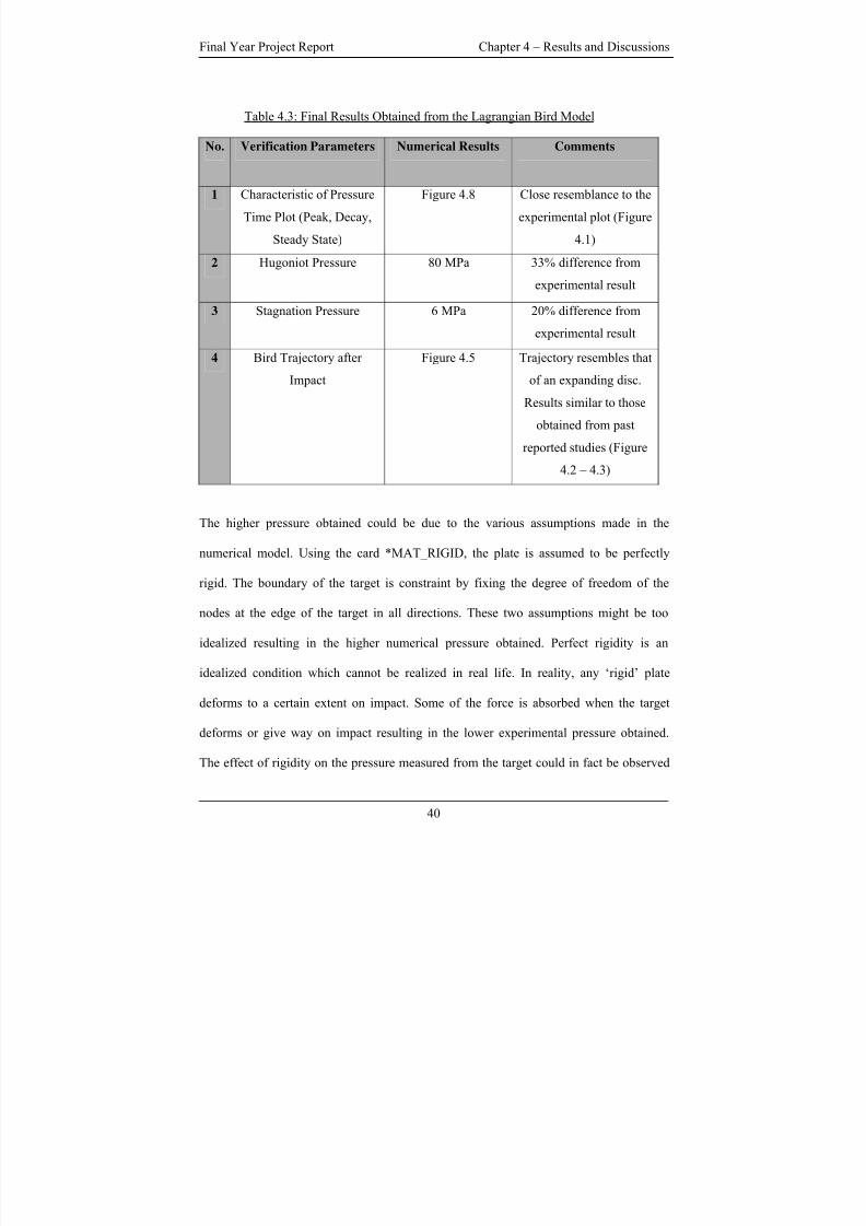
After refining the Lagrangian bird model and investigating the reliability of the bird
material used, a refined Lagrangian bird model with the original bird material, the
original mesh density and a time step scale factor of 0.7 is modeled. The final numerical
results are summarized in table 4.3. As seen from table 4.3, close resemblance could be
obtained for the characteristic of the pressure time plot as well as the bird trajectory after
impact. Higher pressure is obtained from the numerical simulation.
39
8/3/2019 Fe Analysis of Bird Strikes on Composite and Glass Panels
http://slidepdf.com/reader/full/fe-analysis-of-bird-strikes-on-composite-and-glass-panels 52/89
Final Year Project Report Chapter 4 – Results and Discussions
Table 4.3: Final Results Obtained from the Lagrangian Bird Model
No. Verification Parameters Numerical Results Comments
1 Characteristic of Pressure
Time Plot (Peak, Decay,
Steady State)
Figure 4.8 Close resemblance to the
experimental plot (Figure
4.1)
2 Hugoniot Pressure 80 MPa 33% difference from
experimental result
3 Stagnation Pressure 6 MPa 20% difference from
experimental result
4 Bird Trajectory after
Impact
Figure 4.5 Trajectory resembles that
of an expanding disc.
Results similar to those
obtained from past
reported studies (Figure
4.2 – 4.3)
The higher pressure obtained could be due to the various assumptions made in the
numerical model. Using the card *MAT_RIGID, the plate is assumed to be perfectly
rigid. The boundary of the target is constraint by fixing the degree of freedom of the
nodes at the edge of the target in all directions. These two assumptions might be too
idealized resulting in the higher numerical pressure obtained. Perfect rigidity is an
idealized condition which cannot be realized in real life. In reality, any ‘rigid’ plate
deforms to a certain extent on impact. Some of the force is absorbed when the target
deforms or give way on impact resulting in the lower experimental pressure obtained.
The effect of rigidity on the pressure measured from the target could in fact be observed
40
8/3/2019 Fe Analysis of Bird Strikes on Composite and Glass Panels
http://slidepdf.com/reader/full/fe-analysis-of-bird-strikes-on-composite-and-glass-panels 53/89
Final Year Project Report Chapter 4 – Results and Discussions
from figure 4.13 whereby a deformable target is used instead of a rigid one. As seen from
figure 4.13, a lower peak pressure is observed when the target is deformable. This further
proves that rigidity of the target does affect the impact response due to bird strike, at least
in terms of the pressure measured after the impact. In experimental impact test, the plate
would most likely be bolted or clamped. The bolt and clamp might give way due to the
high impact force experienced from the impact. By assuming a boundary condition
whereby the edges are perfectly constrained is not an accurate representation of the real
experiment condition.
The various discrepancies might also be due to the idealization made in the bird model.
The shape of the bird is assumed to be a cylindrical with two hemispherical ends. The
material property of the bird is assumed to be homogenous and isotropic. In reality, real
bird lack homogeneity, isotropy and symmetry. Furthermore, experimental studies are
usually accompanied with factors that are beyond control such as the orientation of the
bird on impact, the point where the initial impact is etc. Numerical model can never
totally predict the experimental result due to the above conditions. A better prediction of
the experimental results will usually be accompanied by a corresponding increase in
computational cost for the numerical model.
The numerical results obtained from the Lagrangian bird model are overall acceptable.
Predicting a higher pressure is more acceptable than predicting a lower pressure since an
aircraft that can take higher load is safer than one that can take lower load.
41
8/3/2019 Fe Analysis of Bird Strikes on Composite and Glass Panels
http://slidepdf.com/reader/full/fe-analysis-of-bird-strikes-on-composite-and-glass-panels 54/89
Final Year Project Report Chapter 4 – Results and Discussions
4.3 EVALUATION OF THE VARIOUS FINITE ELEMENT
FORMULATIONS
The ALE and SPH bird model are modeled as discussed in section 3.1, 3.3, 3.5 and 3.6.
The bird parameters as validated by the Lagrangian bird model are used. Results from the
Lagrangian bird serves as a baseline for comparison. The numerical results are obtained
from an element at the centre of a deformable aluminum plate modeled using the
parameters of table 3.3.
In the assessment on the suitability of the SPH and ALE formulation in modeling bird
strike based on the Lagrangian formulation, there are in fact many aspects of numerical
results that can be compared against. In this preliminary assessment of the various
formulations, the numerical results that are chosen for comparison includes the plot of
effective stress, resultant displacement and pressure at the centre of the aluminum plate as
well as the energy plot. Other aspects that are compared in this study include the bird
trajectory after the impact, the ease of modeling and the computational time required.
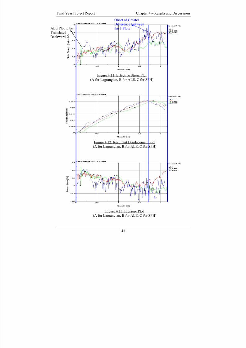
Figure 4.11 to 4.13 shows the numerical results obtained from the various formulations.
These results are taken for comparison after the respective formulations are compared
with a higher mesh density or higher density of particles of their own formulations
whereby no significant difference in the results are observed. Refer to Appendix G for the
plots of the various formulations.
42
8/3/2019 Fe Analysis of Bird Strikes on Composite and Glass Panels
http://slidepdf.com/reader/full/fe-analysis-of-bird-strikes-on-composite-and-glass-panels 55/89
Final Year Project Report Chapter 4 – Results and Discussions
Figure 4.11: Effective Stress Plot
(A for Lagrangian, B for ALE, C for SPH)
Figure 4.12: Resultant Displacement Plot(A for Lagrangian, B for ALE, C for SPH)
ALE Plot to be
Translated
Backward
Onset of Greater
Difference Between
the 3 Plots
Figure 4.13: Pressure Plot
(A for Lagrangian, B for ALE, C for SPH)
43
8/3/2019 Fe Analysis of Bird Strikes on Composite and Glass Panels
http://slidepdf.com/reader/full/fe-analysis-of-bird-strikes-on-composite-and-glass-panels 56/89
Final Year Project Report Chapter 4 – Results and Discussions
Referring to figures 4.11 to 4.13, the simulated results for the various formulations show
close agreement with one another, at least in terms of the trend showed by the curve of
the various formulations. It should be noted that the curve for the ALE formulation
should be translated a few milliseconds to the left as the initial time of contact occurs at a
later stage compared to the Lagrangian and SPH formulation. This is because the ALE
bird is initially position further away from the plate than the SPH and Lagrangian bird
model.
Referring to figure 4.12, the resultant displacement plot has the closest agreement among
the three plots compared. All three formulations show an increasing trend in the
magnitude of the resultant displacement up to about 1.75 milliseconds whereby it reaches
a maximum and then decrease thereafter. All three displacement curve shows
approximately similar gradient up till the maximum point. There is a slight difference in
gradient for the downward part of the displacement plot which resulted in a difference in
the final resultant displacement. The prediction of the 3 different bird model shows less
agreement when the elastic plate starts to deform back to its original shape.
Referring to figure 4.11 and 4.13, all 3 formulations predicted the same trend for the
effective stress plot and the pressure plot. Similar to the displacement plot, the plots of all
3 formulations showed close conformity up till about 1.75 milliseconds, the onset of
greater variation between the 3 plots. The effective stress and pressure plots predicted by
the 3 different formulations shows greater disagreement at termination time compared to
the resultant displacement plot. This is because effective stress and pressure are both
44
8/3/2019 Fe Analysis of Bird Strikes on Composite and Glass Panels
http://slidepdf.com/reader/full/fe-analysis-of-bird-strikes-on-composite-and-glass-panels 57/89
Final Year Project Report Chapter 4 – Results and Discussions
functions of displacement. Since there is a discrepancy in the prediction of displacement,
this discrepancy manifest itself in the calculation of effective stress and pressure thus
explaining the greater variation at termination time (1.75ms onwards) in the effective
stress and pressure plot.
Figure 4.14 to 4.16 shows the energy plot for the various formulations after the impact.
Figure 4.14 shows the internal energy plot, figure 4.15 shows the kinetic energy plot and
figure 4.16 shows the total energy plot. As observed from figure 4.16, the total energy
lost is lowest for the Lagrangian bird model compared to the ALE and SPH bird model.
Theoretically the SPH model should give a lower lost in total energy compared to the
Lagrangian model as problem such as hourglass energy are not present in SPH model.
However this is not the case as observed in figure 4.16. This is probably because a
quarter bird is modeled for the Lagrangian model while on the other hand, a full model is
modeled for the SPH and ALE bird model. Alternatively, a more proper meshing of the
SPH model using a SPH generator as oppose to the unconventional replacement of the
element nodes to SPH particles might perhaps results in a lower lost in the total energy.
As observed from figure 4.16, there is a sharp drop in the total energy for the ALE model
for the first 0.5 milliseconds after which the total energy remains relatively constant.
Referring to figure 4.14, the ALE model has a non-zero initial internal energy. This is
attributed to the internal energy of the air surrounding the ALE bird model. The initial
total energy lost is probably the internal energy of the air surrounding the ALE bird
model. All three models show a decrease in kinetic energy after the impact and a
corresponding increase in internal energy as observed from figure 4.14 and 4.15.
45
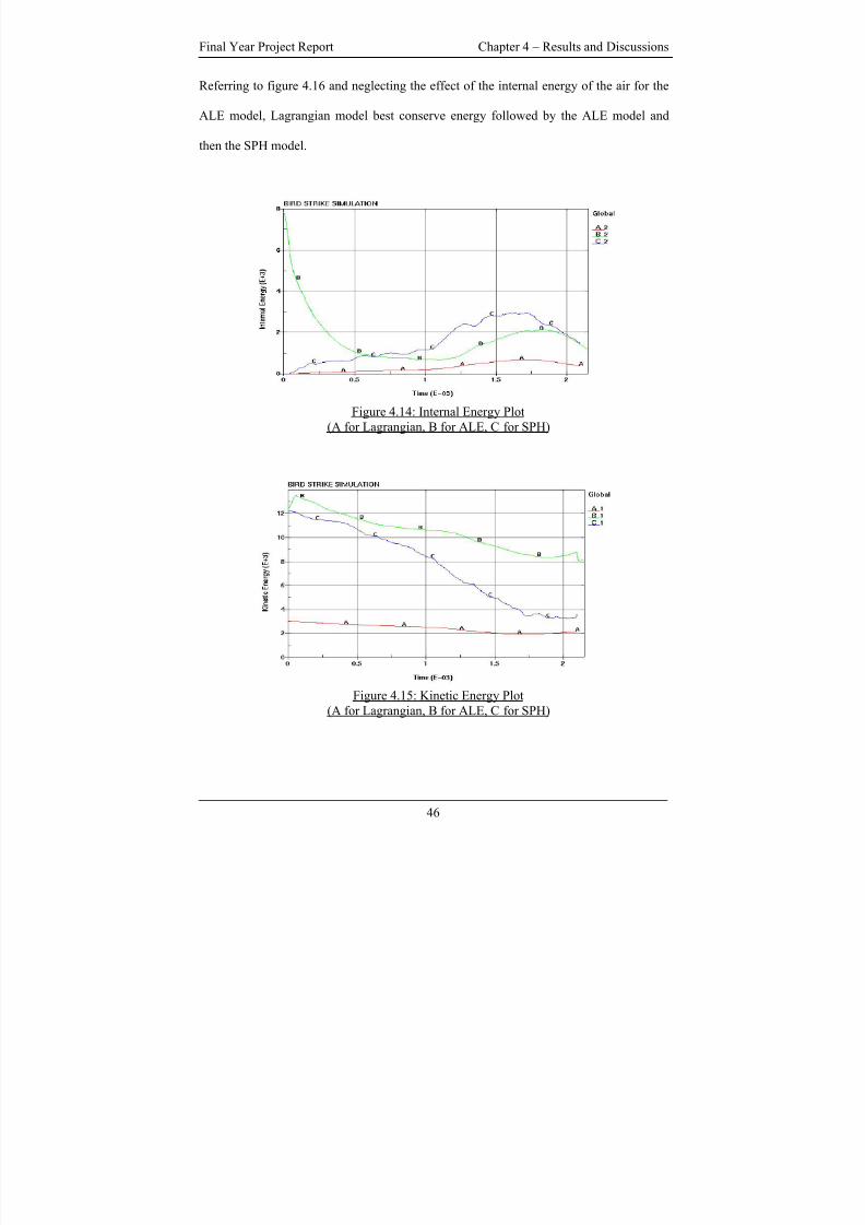
8/3/2019 Fe Analysis of Bird Strikes on Composite and Glass Panels
http://slidepdf.com/reader/full/fe-analysis-of-bird-strikes-on-composite-and-glass-panels 58/89
Final Year Project Report Chapter 4 – Results and Discussions
Referring to figure 4.16 and neglecting the effect of the internal energy of the air for the
ALE model, Lagrangian model best conserve energy followed by the ALE model and
then the SPH model.
Figure 4.14: Internal Energy Plot
(A for Lagrangian, B for ALE, C for SPH)
Figure 4.15: Kinetic Energy Plot
(A for Lagrangian, B for ALE, C for SPH)
46
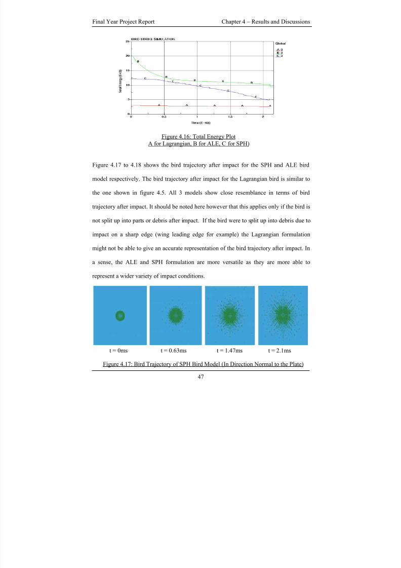
8/3/2019 Fe Analysis of Bird Strikes on Composite and Glass Panels
http://slidepdf.com/reader/full/fe-analysis-of-bird-strikes-on-composite-and-glass-panels 59/89
Final Year Project Report Chapter 4 – Results and Discussions
Figure 4.16: Total Energy Plot
A for Lagrangian, B for ALE, C for SPH)
Figure 4.17 to 4.18 shows the bird trajectory after impact for the SPH and ALE bird
model respectively. The bird trajectory after impact for the Lagrangian bird is similar to
the one shown in figure 4.5. All 3 models show close resemblance in terms of bird
trajectory after impact. It should be noted here however that this applies only if the bird is
not split up into parts or debris after impact. If the bird were to split up into debris due to
impact on a sharp edge (wing leading edge for example) the Lagrangian formulation
might not be able to give an accurate representation of the bird trajectory after impact. In
a sense, the ALE and SPH formulation are more versatile as they are more able to
represent a wider variety of impact conditions.
t = 0ms t = 0.63ms t = 1.47ms t = 2.1ms
Figure 4.17: Bird Trajectory of SPH Bird Model (In Direction Normal to the Plate)
47

8/3/2019 Fe Analysis of Bird Strikes on Composite and Glass Panels
http://slidepdf.com/reader/full/fe-analysis-of-bird-strikes-on-composite-and-glass-panels 60/89
Final Year Project Report Chapter 4 – Results and Discussions
t = 0ms t = 0.63ms t = 1.47ms t = 2.1ms t = 2.15ms
Figure 4.18: Bird Trajectory of ALE Bird Model (In Direction Normal to the Plate)
Comparing the ease of modeling the bird of the various formulations, it is relative easier
to model the SPH and the Lagrangian model compared to the ALE model. The SPH and
Lagrangian model requires only the definition of the particle’s or element’s position in
space. Modeling of the ALE model requires more effort on the other hand. This is
because the ALE model requires the bird material to be contained within the ALE mesh
at all time throughout the simulation. The meshing of the ALE model requires some trial
and error and it is only through simulation that one is able to know if the mesh had
adequately contain the bird material. This trial and error process to ensure the most
efficient mesh takes up valuable preprocessing time.
Finally table 4.4 shows the computational time required by the various formulations. This
includes formulation base on the higher mesh or particle density as well. To reinstate, the
various results compared earlier are based on the bird model with the lower mesh density
or particle density.
48
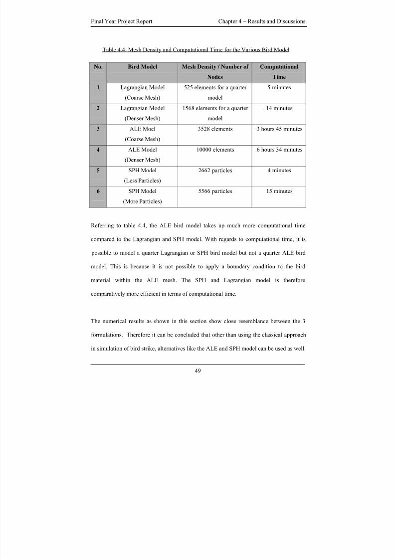
8/3/2019 Fe Analysis of Bird Strikes on Composite and Glass Panels
http://slidepdf.com/reader/full/fe-analysis-of-bird-strikes-on-composite-and-glass-panels 61/89
Final Year Project Report Chapter 4 – Results and Discussions
Table 4.4: Mesh Density and Computational Time for the Various Bird Model
No. Bird Model Mesh Density / Number of
Nodes
Computational
Time
1 Lagrangian Model
(Coarse Mesh)
525 elements for a quarter
model
5 minutes
2 Lagrangian Model
(Denser Mesh)
1568 elements for a quarter
model
14 minutes
3 ALE Moel
(Coarse Mesh)
3528 elements 3 hours 45 minutes
4 ALE Model(Denser Mesh)
10000 elements 6 hours 34 minutes
5 SPH Model
(Less Particles)
2662 particles 4 minutes
6 SPH Model
(More Particles)
5566 particles 15 minutes
Referring to table 4.4, the ALE bird model takes up much more computational time
compared to the Lagrangian and SPH model. With regards to computational time, it is
possible to model a quarter Lagrangian or SPH bird model but not a quarter ALE bird
model. This is because it is not possible to apply a boundary condition to the bird
material within the ALE mesh. The SPH and Lagrangian model is therefore
comparatively more efficient in terms of computational time.
The numerical results as shown in this section show close resemblance between the 3
formulations. Therefore it can be concluded that other than using the classical approach
in simulation of bird strike, alternatives like the ALE and SPH model can be used as well.
49
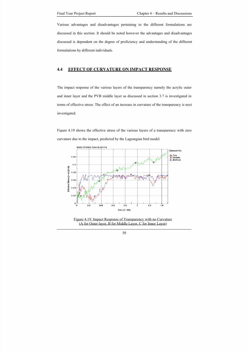
8/3/2019 Fe Analysis of Bird Strikes on Composite and Glass Panels
http://slidepdf.com/reader/full/fe-analysis-of-bird-strikes-on-composite-and-glass-panels 62/89
Final Year Project Report Chapter 4 – Results and Discussions
Various advantages and disadvantages pertaining to the different formulations are
discussed in this section. It should be noted however the advantages and disadvantages
discussed is dependent on the degree of proficiency and understanding of the different
formulations by different individuals.
4.4 EFFECT OF CURVATURE ON IMPACT RESPONSE
The impact response of the various layers of the transparency namely the acrylic outer
and inner layer and the PVB middle layer as discussed in section 3.7 is investigated in
terms of effective stress. The effect of an increase in curvature of the transparency is next
investigated.
Figure 4.19 shows the effective stress of the various layers of a transparency with zero
curvature due to the impact, predicted by the Lagrangian bird model.
Figure 4.19: Impact Response of Transparency with no Curvature
(A for Outer layer, B for Middle Layer, C for Inner Layer)
50
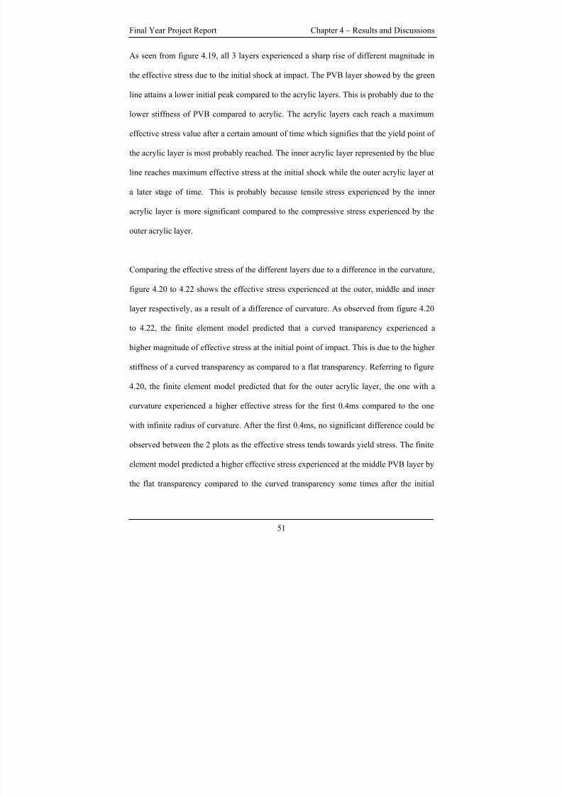
8/3/2019 Fe Analysis of Bird Strikes on Composite and Glass Panels
http://slidepdf.com/reader/full/fe-analysis-of-bird-strikes-on-composite-and-glass-panels 63/89
Final Year Project Report Chapter 4 – Results and Discussions
As seen from figure 4.19, all 3 layers experienced a sharp rise of different magnitude in
the effective stress due to the initial shock at impact. The PVB layer showed by the green
line attains a lower initial peak compared to the acrylic layers. This is probably due to the
lower stiffness of PVB compared to acrylic. The acrylic layers each reach a maximum
effective stress value after a certain amount of time which signifies that the yield point of
the acrylic layer is most probably reached. The inner acrylic layer represented by the blue
line reaches maximum effective stress at the initial shock while the outer acrylic layer at
a later stage of time. This is probably because tensile stress experienced by the inner
acrylic layer is more significant compared to the compressive stress experienced by the
outer acrylic layer.
Comparing the effective stress of the different layers due to a difference in the curvature,
figure 4.20 to 4.22 shows the effective stress experienced at the outer, middle and inner
layer respectively, as a result of a difference of curvature. As observed from figure 4.20
to 4.22, the finite element model predicted that a curved transparency experienced a
higher magnitude of effective stress at the initial point of impact. This is due to the higher
stiffness of a curved transparency as compared to a flat transparency. Referring to figure
4.20, the finite element model predicted that for the outer acrylic layer, the one with a
curvature experienced a higher effective stress for the first 0.4ms compared to the one
with infinite radius of curvature. After the first 0.4ms, no significant difference could be
observed between the 2 plots as the effective stress tends towards yield stress. The finite
element model predicted a higher effective stress experienced at the middle PVB layer by
the flat transparency compared to the curved transparency some times after the initial
51
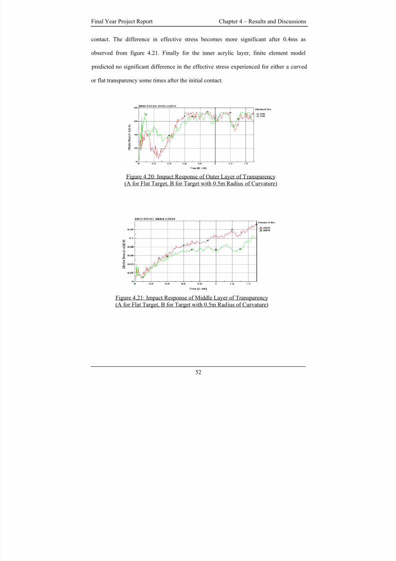
8/3/2019 Fe Analysis of Bird Strikes on Composite and Glass Panels
http://slidepdf.com/reader/full/fe-analysis-of-bird-strikes-on-composite-and-glass-panels 64/89
Final Year Project Report Chapter 4 – Results and Discussions
contact. The difference in effective stress becomes more significant after 0.4ms as
observed from figure 4.21. Finally for the inner acrylic layer, finite element model
predicted no significant difference in the effective stress experienced for either a curved
or flat transparency some times after the initial contact.
Figure 4.20: Impact Response of Outer Layer of Transparency
(A for Flat Target, B for Target with 0.5m Radius of Curvature)
Figure 4.21: Impact Response of Middle Layer of Transparency
(A for Flat Target, B for Target with 0.5m Radius of Curvature)
52
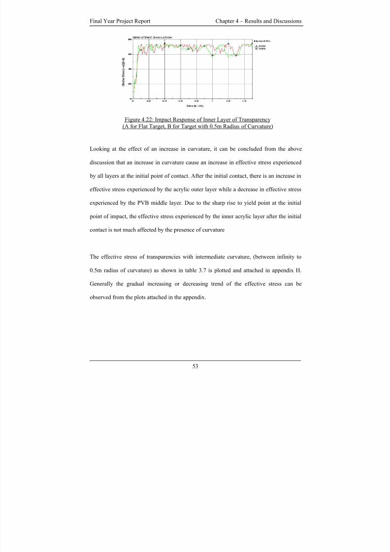
8/3/2019 Fe Analysis of Bird Strikes on Composite and Glass Panels
http://slidepdf.com/reader/full/fe-analysis-of-bird-strikes-on-composite-and-glass-panels 65/89
Final Year Project Report Chapter 4 – Results and Discussions
Figure 4.22: Impact Response of Inner Layer of Transparency
(A for Flat Target, B for Target with 0.5m Radius of Curvature)
Looking at the effect of an increase in curvature, it can be concluded from the above
discussion that an increase in curvature cause an increase in effective stress experienced
by all layers at the initial point of contact. After the initial contact, there is an increase in
effective stress experienced by the acrylic outer layer while a decrease in effective stress
experienced by the PVB middle layer. Due to the sharp rise to yield point at the initial
point of impact, the effective stress experienced by the inner acrylic layer after the initial
contact is not much affected by the presence of curvature
The effective stress of transparencies with intermediate curvature, (between infinity to
0.5m radius of curvature) as shown in table 3.7 is plotted and attached in appendix H.
Generally the gradual increasing or decreasing trend of the effective stress can be
observed from the plots attached in the appendix.
53
8/3/2019 Fe Analysis of Bird Strikes on Composite and Glass Panels
http://slidepdf.com/reader/full/fe-analysis-of-bird-strikes-on-composite-and-glass-panels 66/89
Final Year Project Report Chapter 5 – Conclusions and Recommendations
CHAPTER FIVE – CONCLUSIONS & RECOMMENDATIONS
5.1 CONCLUSIONS AND RECOMMENDATIONS
The results obtained from the simulation of the impact of the Lagrangian bird model on a
rigid target showed that results obtained from numerical simulation is comparable to
experimental one in terms of pressure profile, Hugoniot and stagnation pressure. Both
Hugoniot and stagnation pressure obtained are higher than the experimental results which
might be attributed to the various assumptions made in modeling the numerical model.
Simulation of bird impact on an elastic aluminum flat panel using different formulations
namely Lagrangian, ALE and SPH yields comparable numerical results. The ALE and
SPH method provides alternatives to the Lagrangian formulation for the simulation of
bird strike. The pros and cons of using the various formulations have been briefly
discussed in this report. Depending on the requirement, different formulations can be
used under different circumstances so as to achieve the most effective outcome. However
the effectiveness and efficiency of using the various formulations depends on the
proficiency of individual as discussed earlier.
The effect of curvature, of an aircraft transparency, on the impact response due to bird
strike has been investigated. However there is a lack of experimental result to validate the
numerical result.
54
8/3/2019 Fe Analysis of Bird Strikes on Composite and Glass Panels
http://slidepdf.com/reader/full/fe-analysis-of-bird-strikes-on-composite-and-glass-panels 67/89
Final Year Project Report Chapter 5 – Conclusions and Recommendations
The numerical study of bird strike has been a much studied topic. Large amount of
money can be saved in the validation of aircraft components with numerical simulations
before the actual testing. This final year project focus on simplified models as the exact
geometrical shape and material properties of the various aircraft components are usually
not readily available in literature. If more information is available, a more realistic model
of the aircraft component could be modeled. This includes a more realistic geometric
shape or material model that better represents the aircraft. With a more realistic model,
more areas of investigation regarding bird strike can be look into. For example, numerical
results can be used to determine the different composition of the aircraft material that
achieves the greatest strength with the least amount of material.
55
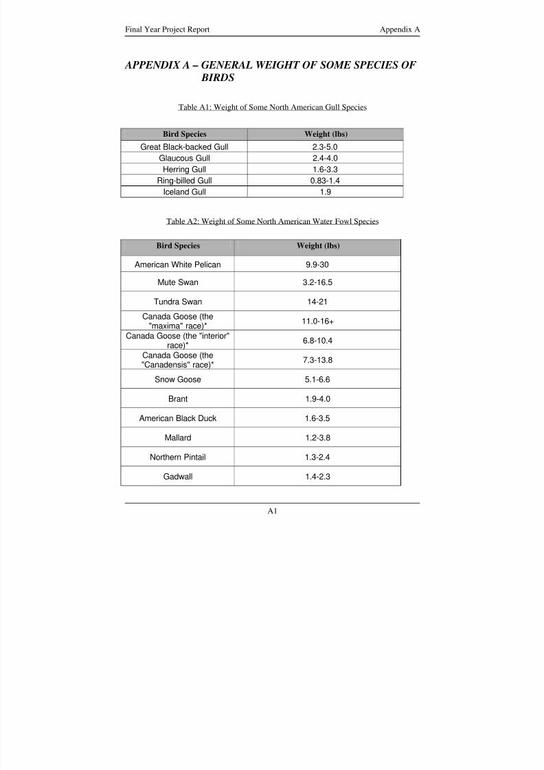
8/3/2019 Fe Analysis of Bird Strikes on Composite and Glass Panels
http://slidepdf.com/reader/full/fe-analysis-of-bird-strikes-on-composite-and-glass-panels 68/89
Final Year Project Report Appendix A
APPENDIX A – GENERAL WEIGHT OF SOME SPECIES OF
BIRDS
Table A1: Weight of Some North American Gull Species
Bird Species Weight (lbs)
Great Black-backed Gull 2.3-5.0
Glaucous Gull 2.4-4.0
Herring Gull 1.6-3.3
Ring-billed Gull 0.83-1.4
Iceland Gull 1.9
Table A2: Weight of Some North American Water Fowl Species
Bird Species Weight (lbs)
American White Pelican 9.9-30
Mute Swan 3.2-16.5
Tundra Swan 14-21
Canada Goose (the"maxima" race)*
11.0-16+
Canada Goose (the "interior"race)*
6.8-10.4
Canada Goose (the"Canadensis" race)*
7.3-13.8
Snow Goose 5.1-6.6
Brant 1.9-4.0
American Black Duck 1.6-3.5
Mallard 1.2-3.8
Northern Pintail 1.3-2.4
Gadwall 1.4-2.3
A1
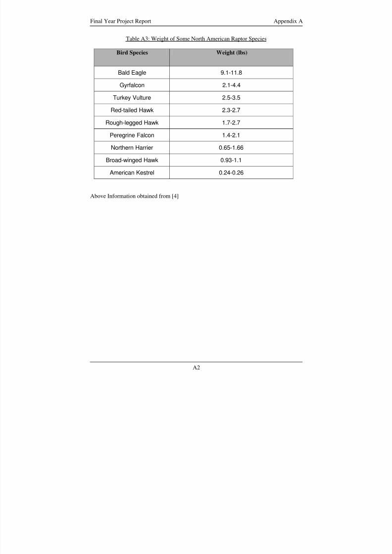
8/3/2019 Fe Analysis of Bird Strikes on Composite and Glass Panels
http://slidepdf.com/reader/full/fe-analysis-of-bird-strikes-on-composite-and-glass-panels 69/89
Final Year Project Report Appendix A
Table A3: Weight of Some North American Raptor Species
Bird Species Weight (lbs)
Bald Eagle 9.1-11.8
Gyrfalcon 2.1-4.4
Turkey Vulture 2.5-3.5
Red-tailed Hawk 2.3-2.7
Rough-legged Hawk 1.7-2.7
Peregrine Falcon 1.4-2.1
Northern Harrier 0.65-1.66
Broad-winged Hawk 0.93-1.1
American Kestrel 0.24-0.26
Above Information obtained from [4]
A2
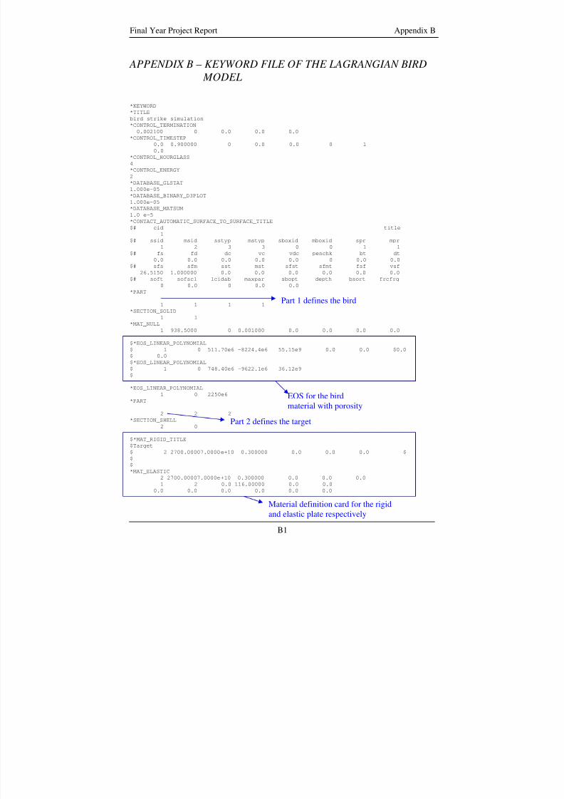
8/3/2019 Fe Analysis of Bird Strikes on Composite and Glass Panels
http://slidepdf.com/reader/full/fe-analysis-of-bird-strikes-on-composite-and-glass-panels 70/89
Final Year Project Report Appendix B
APPENDIX B – KEYWORD FILE OF THE LAGRANGIAN BIRD
MODEL
*KEYWORD*TITLE
bird strike simulation
*CONTROL_TERMINATION
0.002100 0 0.0 0.0 0.0
*CONTROL_TIMESTEP
0.0 0.900000 0 0.0 0.0 0 1
0.0
*CONTROL_HOURGLASS
4
*CONTROL_ENERGY
2
*DATABASE_GLSTAT
1.000e-05
*DATABASE_BINARY_D3PLOT
1.000e-05
*DATABASE_MATSUM
1.0 e-5*CONTACT_AUTOMATIC_SURFACE_TO_SURFACE_TITLE
$# cid title
1
$# ssid msid sstyp mstyp sboxid mboxid spr mpr
1 2 3 3 0 0 1 1
$# fs fd dc vc vdc penchk bt dt
0.0 0.0 0.0 0.0 0.0 0 0.0 0.0
$# sfs sfm sst mst sfst sfmt fsf vsf
26.5150 1.000000 0.0 0.0 0.0 0.0 0.0 0.0
$# soft sofscl lcidab maxpar sbopt depth bsort frcfrq
0 0.0 0 0.0 0.0
*PART
Part 1 defines the bird1 1 1 1
*SECTION_SOLID
1 1
*MAT_NULL1 938.5000 0 0.001000 0.0 0.0 0.0 0.0
$*EOS_LINEAR_POLYNOMIAL
$ 1 0 511.70e6 -8224.4e6 55.15e9 0.0 0.0 $0.0
$ 0.0
$*EOS_LINEAR_POLYNOMIAL
$ 1 0 748.40e6 -9622.1e6 36.12e9
$
*EOS_LINEAR_POLYNOMIAL
1 0 2250e6
*PARTEOS for the bird
material with porosity2 2 2
*SECTION_SHELL Part 2 defines the target2 0
$*MAT_RIGID_TITLE
$Target
$ 2 2700.00007.0000e+10 0.300000 0.0 0.0 0.0 $
$
$
*MAT_ELASTIC
2 2700.00007.0000e+10 0.300000 0.0 0.0 0.0
1 2 0.0 116.00000 0.0 0.0
0.0 0.0 0.0 0.0 0.0 0.0
Material definition card for the rigid
and elastic plate respectively
B1
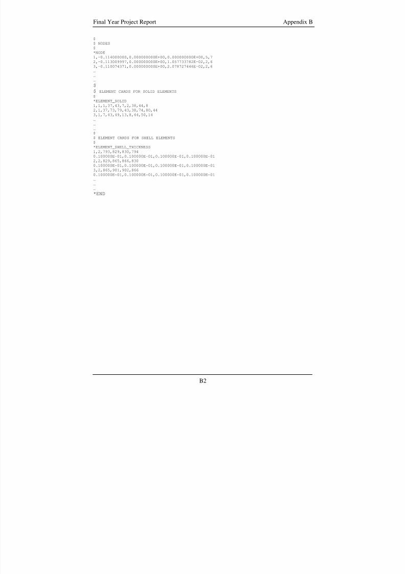
8/3/2019 Fe Analysis of Bird Strikes on Composite and Glass Panels
http://slidepdf.com/reader/full/fe-analysis-of-bird-strikes-on-composite-and-glass-panels 71/89
Final Year Project Report Appendix B
$
$ NODES
$
*NODE
1,-0.114000000,0.000000000E+00,0.000000000E+00,5,7
2,-0.113009997,0.000000000E+00,1.057733782E-02,2,6
3,-0.110074371,0.000000000E+00,2.078727446E-02,2,6
…
……
$
$ ELEMENT CARDS FOR SOLID ELEMENTS
$
*ELEMENT_SOLID
1,1,1,37,43,7,2,38,44,8
2,1,37,73,79,43,38,74,80,44
3,1,7,43,49,13,8,44,50,14
…
…
…
$
$ ELEMENT CARDS FOR SHELL ELEMENTS
$
*ELEMENT_SHELL_THICKNESS
1,2,793,829,830,794
0.100000E-01,0.100000E-01,0.100000E-01,0.100000E-012,2,829,865,866,830
0.100000E-01,0.100000E-01,0.100000E-01,0.100000E-01
3,2,865,901,902,866
0.100000E-01,0.100000E-01,0.100000E-01,0.100000E-01
…
…
…
*END
B2
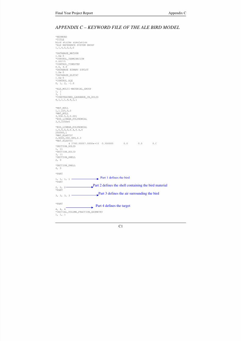
8/3/2019 Fe Analysis of Bird Strikes on Composite and Glass Panels
http://slidepdf.com/reader/full/fe-analysis-of-bird-strikes-on-composite-and-glass-panels 72/89
Final Year Project Report Appendix C
APPENDIX C – KEYWORD FILE OF THE ALE BIRD MODEL
*KEYWORD
*TITLE
bird strike simulation
*ALE_REFERENCE_SYSTEM_GROUP1,1,4,0,0,0,0
*DATABASE_MATSUM
1.0e-5
*CONTROL_TERMINATION
0.00215
*CONTROL_TIMESTEP
0.0, 0.9
*DATABASE_BINARY_D3PLOT
1.0e-5
*DATABASE_GLSTAT
1.0e-5
*CONTROL_ALE
0, 1, 2, -1.0
*ALE_MULTI-MATERIAL_GROUP
1, 13, 1
*CONSTRAINED_LAGRANGE_IN_SOLID
4,1,1,1,4,4,2,1
*MAT_NULL
1,1.225,0,0
*MAT_NULL
3,938.5,0,0.001
*EOS_LINEAR_POLYNOMIAL
3,0,2250e6
*EOS_LINEAR_POLYNOMIAL
1,0,0,0,0,0.4,0.4,0
250000,1
*MAT_ELASTIC
2,8000,200.0E9,0.3*MAT_ELASTIC
4 2700.00007.0000e+10 0.300000 0.0 0.0 0.0
*SECTION_SOLID
1, 11
*SECTION_SOLID
3, 11
*SECTION_SHELL
2, 0
*SECTION_SHELL
4, 0
*PART
Part 1 defines the bird1, 1, 1, 1
*PART
2, 2, 2Part 2 defines the shell containing the bird material
*PART
Part 3 defines the air surrounding the bird3, 3, 3, 3
*PARTPart 4 defines the target
4, 4, 4
*INITIAL_VOLUME_FRACTION_GEOMETRY
1, 1, 1
C1
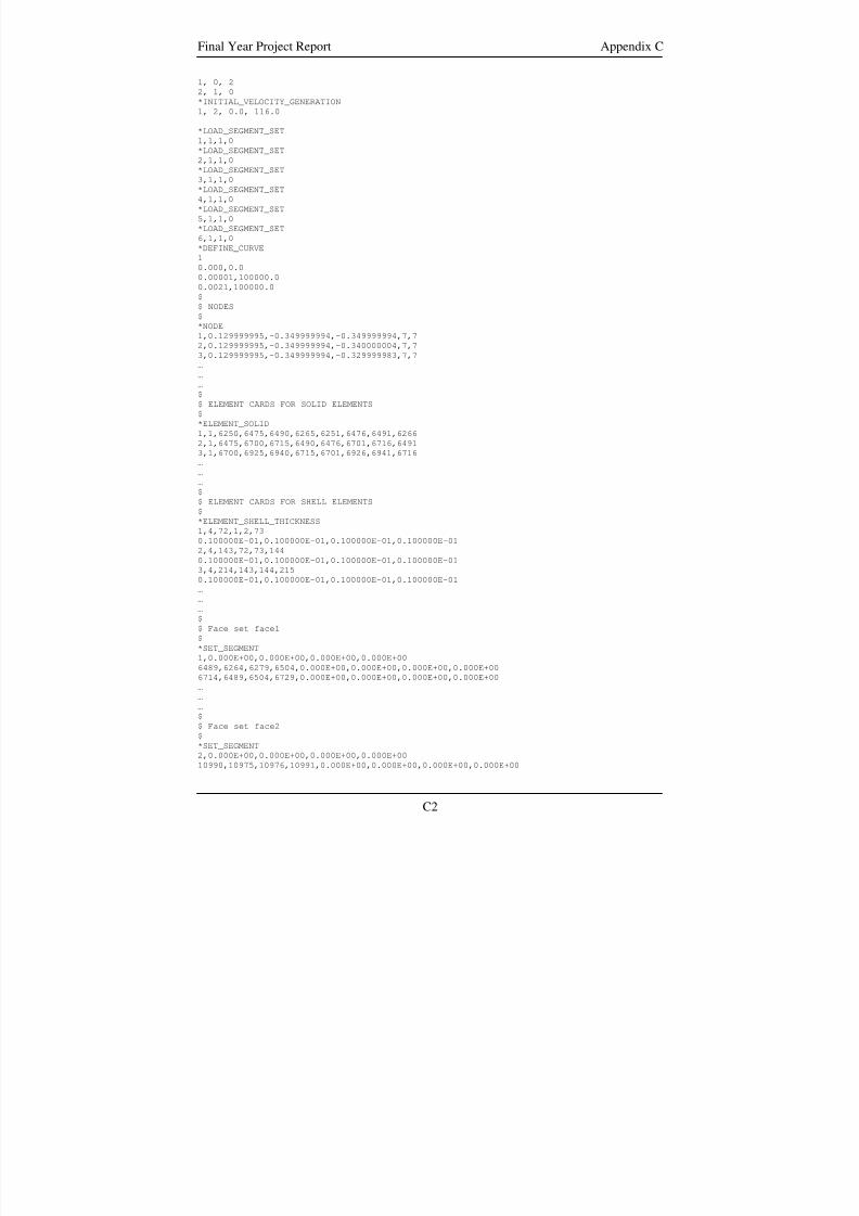
8/3/2019 Fe Analysis of Bird Strikes on Composite and Glass Panels
http://slidepdf.com/reader/full/fe-analysis-of-bird-strikes-on-composite-and-glass-panels 73/89
Final Year Project Report Appendix C
1, 0, 2
2, 1, 0
*INITIAL_VELOCITY_GENERATION
1, 2, 0.0, 116.0
*LOAD_SEGMENT_SET
1,1,1,0
*LOAD_SEGMENT_SET
2,1,1,0
*LOAD_SEGMENT_SET
3,1,1,0
*LOAD_SEGMENT_SET
4,1,1,0
*LOAD_SEGMENT_SET
5,1,1,0
*LOAD_SEGMENT_SET
6,1,1,0
*DEFINE_CURVE
1
0.000,0.0
0.00001,100000.0
0.0021,100000.0
$
$ NODES
$
*NODE1,0.129999995,-0.349999994,-0.349999994,7,7
2,0.129999995,-0.349999994,-0.340000004,7,7
3,0.129999995,-0.349999994,-0.329999983,7,7
…
…
…
$
$ ELEMENT CARDS FOR SOLID ELEMENTS
$
*ELEMENT_SOLID
1,1,6250,6475,6490,6265,6251,6476,6491,6266
2,1,6475,6700,6715,6490,6476,6701,6716,6491
3,1,6700,6925,6940,6715,6701,6926,6941,6716
…
…
…
$$ ELEMENT CARDS FOR SHELL ELEMENTS
$
*ELEMENT_SHELL_THICKNESS
1,4,72,1,2,73
0.100000E-01,0.100000E-01,0.100000E-01,0.100000E-01
2,4,143,72,73,144
0.100000E-01,0.100000E-01,0.100000E-01,0.100000E-01
3,4,214,143,144,215
0.100000E-01,0.100000E-01,0.100000E-01,0.100000E-01
…
…
…
$
$ Face set face1
$
*SET_SEGMENT
1,0.000E+00,0.000E+00,0.000E+00,0.000E+006489,6264,6279,6504,0.000E+00,0.000E+00,0.000E+00,0.000E+00
6714,6489,6504,6729,0.000E+00,0.000E+00,0.000E+00,0.000E+00
…
…
…
$
$ Face set face2
$
*SET_SEGMENT
2,0.000E+00,0.000E+00,0.000E+00,0.000E+00
10990,10975,10976,10991,0.000E+00,0.000E+00,0.000E+00,0.000E+00
C2
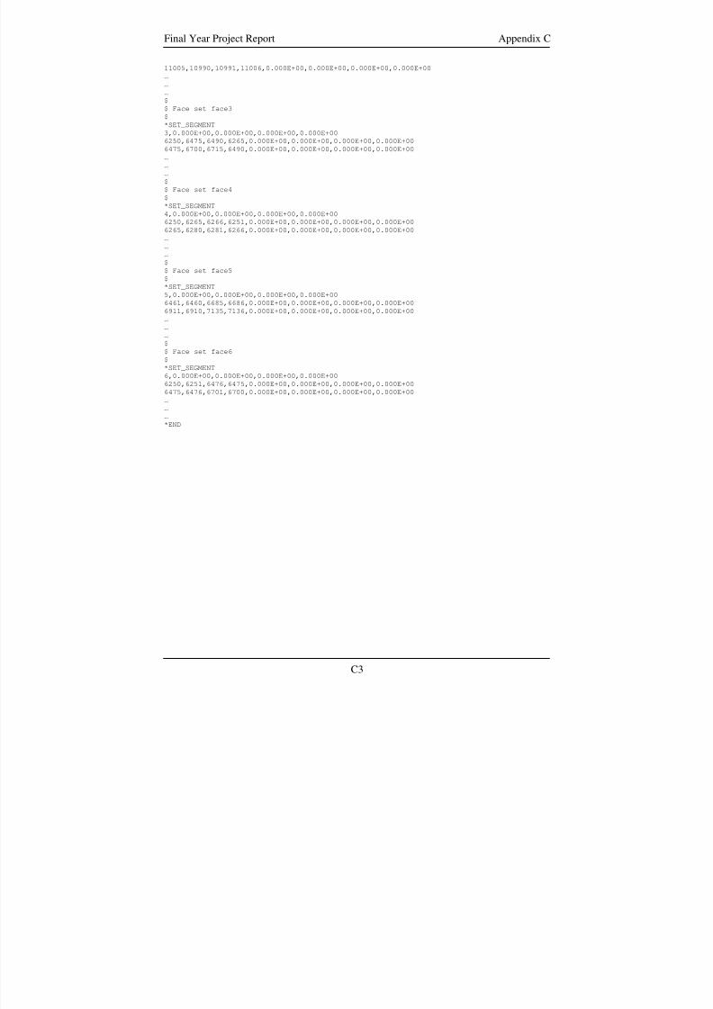
8/3/2019 Fe Analysis of Bird Strikes on Composite and Glass Panels
http://slidepdf.com/reader/full/fe-analysis-of-bird-strikes-on-composite-and-glass-panels 74/89
Final Year Project Report Appendix C
11005,10990,10991,11006,0.000E+00,0.000E+00,0.000E+00,0.000E+00
…
…
…
$
$ Face set face3
$
*SET_SEGMENT
3,0.000E+00,0.000E+00,0.000E+00,0.000E+00
6250,6475,6490,6265,0.000E+00,0.000E+00,0.000E+00,0.000E+00
6475,6700,6715,6490,0.000E+00,0.000E+00,0.000E+00,0.000E+00
…
…
…
$
$ Face set face4
$
*SET_SEGMENT
4,0.000E+00,0.000E+00,0.000E+00,0.000E+00
6250,6265,6266,6251,0.000E+00,0.000E+00,0.000E+00,0.000E+00
6265,6280,6281,6266,0.000E+00,0.000E+00,0.000E+00,0.000E+00
…
…
…
$
$ Face set face5$
*SET_SEGMENT
5,0.000E+00,0.000E+00,0.000E+00,0.000E+00
6461,6460,6685,6686,0.000E+00,0.000E+00,0.000E+00,0.000E+00
6911,6910,7135,7136,0.000E+00,0.000E+00,0.000E+00,0.000E+00
…
…
…
$
$ Face set face6
$
*SET_SEGMENT
6,0.000E+00,0.000E+00,0.000E+00,0.000E+00
6250,6251,6476,6475,0.000E+00,0.000E+00,0.000E+00,0.000E+00
6475,6476,6701,6700,0.000E+00,0.000E+00,0.000E+00,0.000E+00
…
……
*END
C3
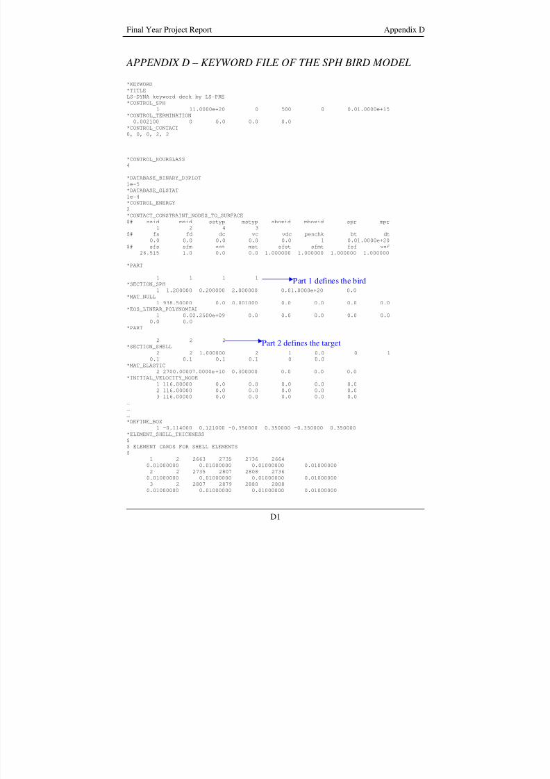
8/3/2019 Fe Analysis of Bird Strikes on Composite and Glass Panels
http://slidepdf.com/reader/full/fe-analysis-of-bird-strikes-on-composite-and-glass-panels 75/89
Final Year Project Report Appendix D
APPENDIX D – KEYWORD FILE OF THE SPH BIRD MODEL
*KEYWORD
*TITLE
LS-DYNA keyword deck by LS-PRE
*CONTROL_SPH1 11.0000e+20 0 500 0 0.01.0000e+15
*CONTROL_TERMINATION
0.002100 0 0.0 0.0 0.0
*CONTROL_CONTACT
0, 0, 0, 2, 2
*CONTROL_HOURGLASS
4
*DATABASE_BINARY_D3PLOT
1e-5
*DATABASE_GLSTAT
1e-4
*CONTROL_ENERGY
2*CONTACT_CONSTRAINT_NODES_TO_SURFACE
$# ssid msid sstyp mstyp sboxid mboxid spr mpr
1 2 4 3
$# fs fd dc vc vdc penchk bt dt
0.0 0.0 0.0 0.0 0.0 1 0.01.0000e+20
$# sfs sfm sst mst sfst sfmt fsf vsf
26.515 1.0 0.0 0.0 1.000000 1.000000 1.000000 1.000000
*PART
1 1 1 1Part 1 defines the bird*SECTION_SPH
1 1.200000 0.200000 2.000000 0.01.0000e+20 0.0
*MAT_NULL
1 938.50000 0.0 0.001000 0.0 0.0 0.0 0.0
*EOS_LINEAR_POLYNOMIAL
1 0.02.2500e+09 0.0 0.0 0.0 0.0 0.00.0 0.0
*PART
2 2 2Part 2 defines the target
*SECTION_SHELL
2 2 1.000000 2 1 0.0 0 1
0.1 0.1 0.1 0.1 0 0.0
*MAT_ELASTIC
2 2700.00007.0000e+10 0.300000 0.0 0.0 0.0
*INITIAL_VELOCITY_NODE
1 116.00000 0.0 0.0 0.0 0.0 0.0
2 116.00000 0.0 0.0 0.0 0.0 0.0
3 116.00000 0.0 0.0 0.0 0.0 0.0
…
…
…
*DEFINE_BOX1 -0.114000 0.121000 -0.350000 0.350000 -0.350000 0.350000
*ELEMENT_SHELL_THICKNESS
$
$ ELEMENT CARDS FOR SHELL ELEMENTS
$
1 2 2663 2735 2736 2664
0.01000000 0.01000000 0.01000000 0.01000000
2 2 2735 2807 2808 2736
0.01000000 0.01000000 0.01000000 0.01000000
3 2 2807 2879 2880 2808
0.01000000 0.01000000 0.01000000 0.01000000
D1
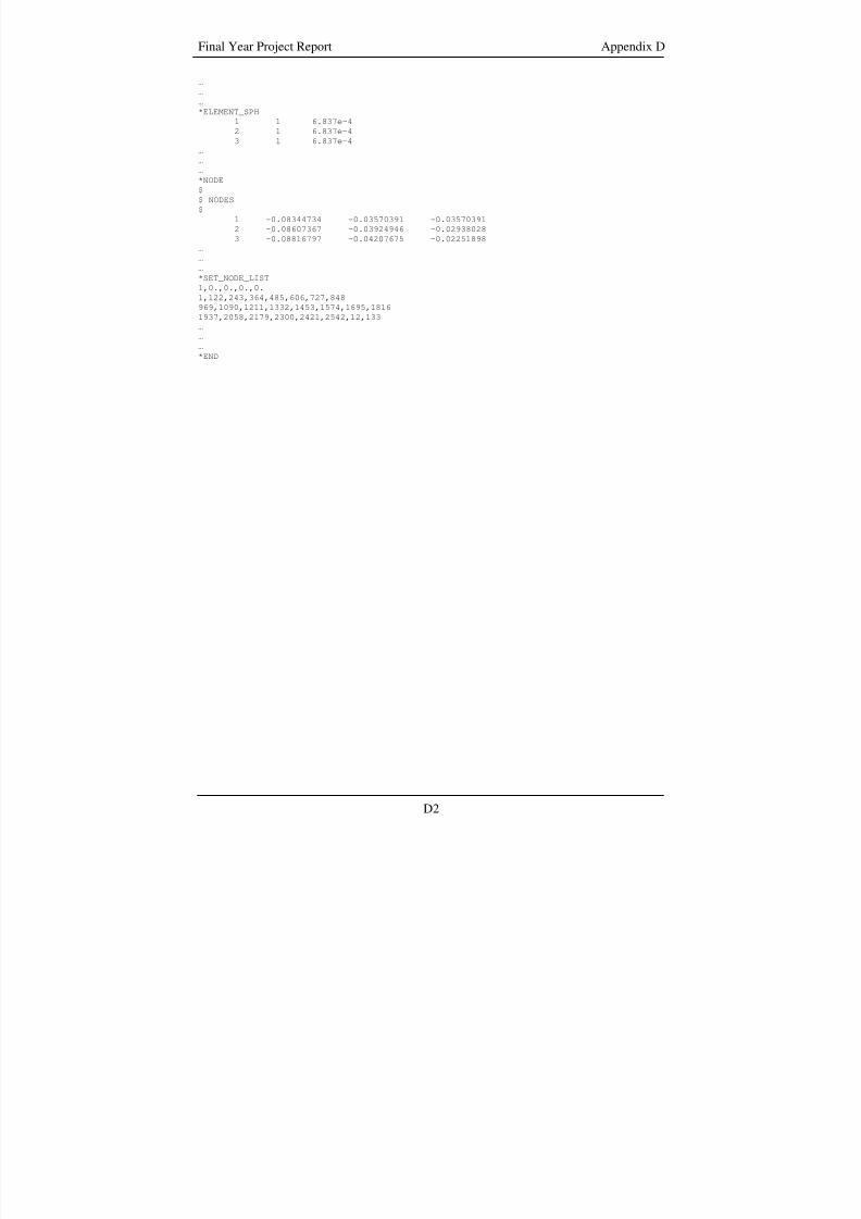
8/3/2019 Fe Analysis of Bird Strikes on Composite and Glass Panels
http://slidepdf.com/reader/full/fe-analysis-of-bird-strikes-on-composite-and-glass-panels 76/89
Final Year Project Report Appendix D
…
…
…
*ELEMENT_SPH
1 1 6.837e-4
2 1 6.837e-4
3 1 6.837e-4
…
……
*NODE
$
$ NODES
$
1 -0.08344734 -0.03570391 -0.03570391
2 -0.08607367 -0.03924946 -0.02938028
3 -0.08816797 -0.04207675 -0.02251898
…
…
…
*SET_NODE_LIST
1,0.,0.,0.,0.
1,122,243,364,485,606,727,848
969,1090,1211,1332,1453,1574,1695,1816
1937,2058,2179,2300,2421,2542,12,133
……
…
*END
D2
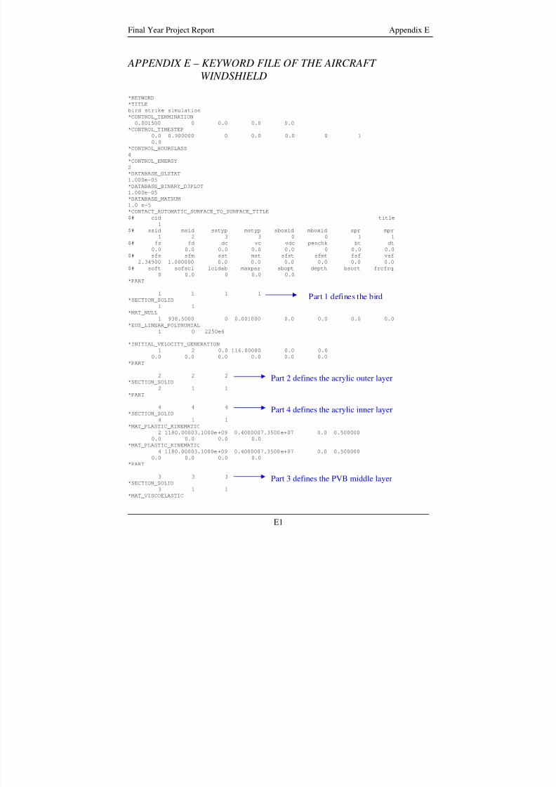
8/3/2019 Fe Analysis of Bird Strikes on Composite and Glass Panels
http://slidepdf.com/reader/full/fe-analysis-of-bird-strikes-on-composite-and-glass-panels 77/89
Final Year Project Report Appendix E
APPENDIX E – KEYWORD FILE OF THE AIRCRAFT
WINDSHIELD
*KEYWORD
*TITLEbird strike simulation
*CONTROL_TERMINATION
0.001500 0 0.0 0.0 0.0
*CONTROL_TIMESTEP
0.0 0.900000 0 0.0 0.0 0 1
0.0
*CONTROL_HOURGLASS
4
*CONTROL_ENERGY
2
*DATABASE_GLSTAT
1.000e-05
*DATABASE_BINARY_D3PLOT
1.000e-05
*DATABASE_MATSUM
1.0 e-5
*CONTACT_AUTOMATIC_SURFACE_TO_SURFACE_TITLE$# cid title
1
$# ssid msid sstyp mstyp sboxid mboxid spr mpr
1 2 3 3 0 0 1 1
$# fs fd dc vc vdc penchk bt dt
0.0 0.0 0.0 0.0 0.0 0 0.0 0.0
$# sfs sfm sst mst sfst sfmt fsf vsf
2.34900 1.000000 0.0 0.0 0.0 0.0 0.0 0.0
$# soft sofscl lcidab maxpar sbopt depth bsort frcfrq
0 0.0 0 0.0 0.0
*PART
1 1 1 1Part 1 defines the bird*SECTION_SOLID
1 1
*MAT_NULL
1 938.5000 0 0.001000 0.0 0.0 0.0 0.0*EOS_LINEAR_POLYNOMIAL
1 0 2250e6
*INITIAL_VELOCITY_GENERATION
1 2 0.0 116.00000 0.0 0.0
0.0 0.0 0.0 0.0 0.0 0.0
*PART
2 2 2 Part 2 defines the acrylic outer layer*SECTION_SOLID
2 1 1
*PART
4 4 4 Part 4 defines the acrylic inner layer*SECTION_SOLID
4 1 1
*MAT_PLASTIC_KINEMATIC2 1180.00003.1000e+09 0.4000007.3500e+07 0.0 0.500000
0.0 0.0 0.0 0.0
*MAT_PLASTIC_KINEMATIC
4 1180.00003.1000e+09 0.4000007.3500e+07 0.0 0.500000
0.0 0.0 0.0 0.0
*PART
3 3 3 Part 3 defines the PVB middle layer*SECTION_SOLID
3 1 1
*MAT_VISCOELASTIC
E1
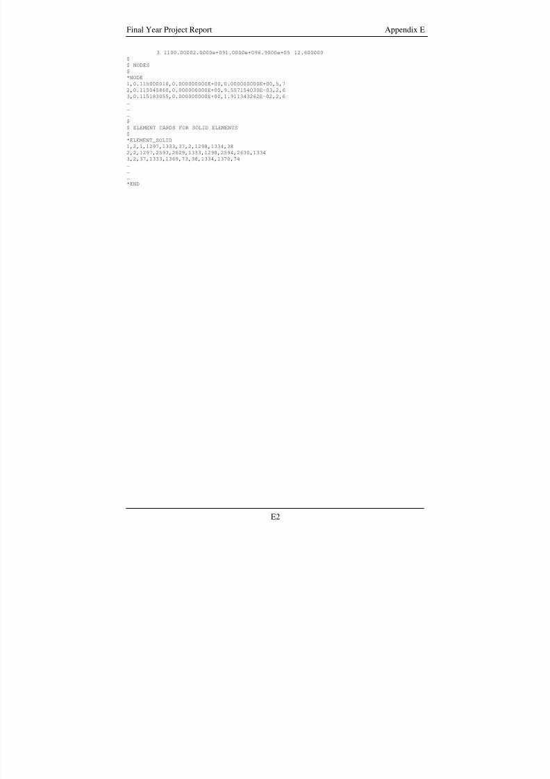
8/3/2019 Fe Analysis of Bird Strikes on Composite and Glass Panels
http://slidepdf.com/reader/full/fe-analysis-of-bird-strikes-on-composite-and-glass-panels 78/89
Final Year Project Report Appendix E
3 1100.00002.0000e+091.0000e+096.9000e+05 12.600000
$
$ NODES
$
*NODE
1,0.115000010,0.000000000E+00,0.000000000E+00,5,7
2,0.115045860,0.000000000E+00,9.557154030E-03,2,6
3,0.115183055,0.000000000E+00,1.911343262E-02,2,6
……
…
$
$ ELEMENT CARDS FOR SOLID ELEMENTS
$
*ELEMENT_SOLID
1,2,1,1297,1333,37,2,1298,1334,38
2,2,1297,2593,2629,1333,1298,2594,2630,1334
3,2,37,1333,1369,73,38,1334,1370,74
…
…
…
*END
E2
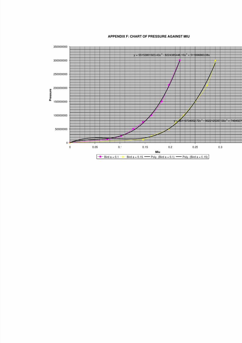
8/3/2019 Fe Analysis of Bird Strikes on Composite and Glass Panels
http://slidepdf.com/reader/full/fe-analysis-of-bird-strikes-on-composite-and-glass-panels 79/89
APPENDIX F: CHART OF PRESSURE AGAINST MIU
y = 55153801923.43x3
- 8224385446.10x2
+ 51169686
y = 36119734952.72x3
0
50000000
100000000
150000000
200000000
250000000
300000000
350000000
0 0.05 0.1 0.15 0.2 0.25
Miu
P r e s s u
r e
Bird a = 0.1 Bird a = 0.15 Poly. (Bird a = 0.1) Poly. (Bird a = 0
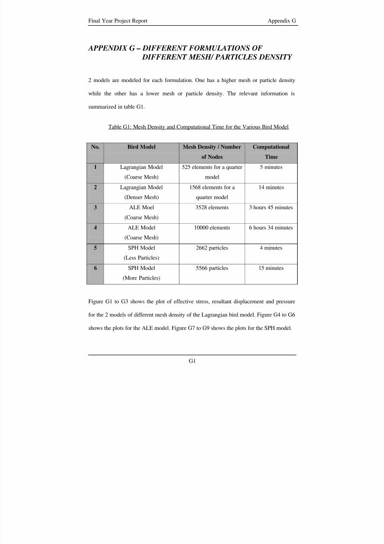
8/3/2019 Fe Analysis of Bird Strikes on Composite and Glass Panels
http://slidepdf.com/reader/full/fe-analysis-of-bird-strikes-on-composite-and-glass-panels 80/89
Final Year Project Report Appendix G
APPENDIX G – DIFFERENT FORMULATIONS OF
DIFFERENT MESH/ PARTICLES DENSITY
2 models are modeled for each formulation. One has a higher mesh or particle density
while the other has a lower mesh or particle density. The relevant information is
summarized in table G1.
Table G1: Mesh Density and Computational Time for the Various Bird Model
No. Bird Model Mesh Density / Number
of Nodes
Computational
Time
1 Lagrangian Model
(Coarse Mesh)
525 elements for a quarter
model
5 minutes
2 Lagrangian Model
(Denser Mesh)
1568 elements for a
quarter model
14 minutes
3 ALE Moel
(Coarse Mesh)
3528 elements 3 hours 45 minutes
4 ALE Model
(Coarse Mesh)
10000 elements 6 hours 34 minutes
5 SPH Model
(Less Particles)
2662 particles 4 minutes
6 SPH Model
(More Particles)
5566 particles 15 minutes
Figure G1 to G3 shows the plot of effective stress, resultant displacement and pressure
for the 2 models of different mesh density of the Lagrangian bird model. Figure G4 to G6
shows the plots for the ALE model. Figure G7 to G9 shows the plots for the SPH model.
G1
8/3/2019 Fe Analysis of Bird Strikes on Composite and Glass Panels
http://slidepdf.com/reader/full/fe-analysis-of-bird-strikes-on-composite-and-glass-panels 81/89
Final Year Project Report Appendix G
Basically the various plots pertaining to each formulation show great resemblance to one
another. The results of this mesh sensitivity study indicate that the relativity coarse
models are sufficient to give a comparable result to the other formulations. Generally, the
more nodes there are the longer the computational time.
G2
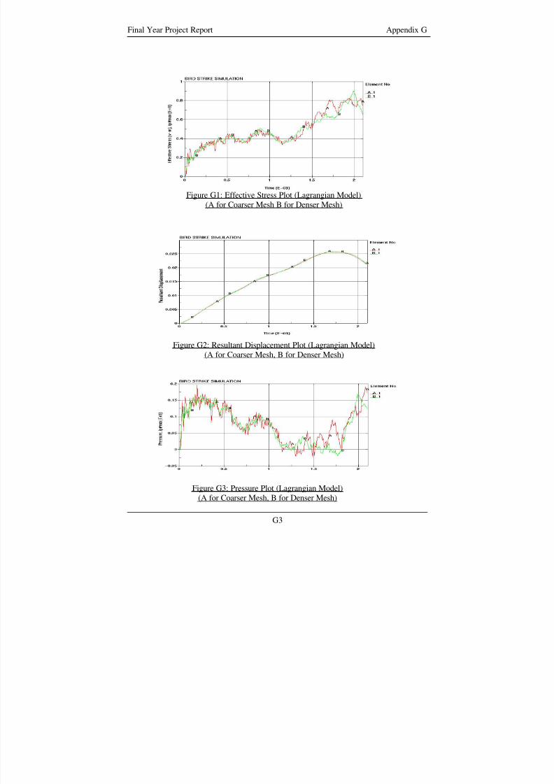
8/3/2019 Fe Analysis of Bird Strikes on Composite and Glass Panels
http://slidepdf.com/reader/full/fe-analysis-of-bird-strikes-on-composite-and-glass-panels 82/89
Final Year Project Report Appendix G
Figure G1: Effective Stress Plot (Lagrangian Model)
(A for Coarser Mesh B for Denser Mesh)
Figure G2: Resultant Displacement Plot (Lagrangian Model)
(A for Coarser Mesh, B for Denser Mesh)
Figure G3: Pressure Plot (Lagrangian Model)
(A for Coarser Mesh, B for Denser Mesh)
G3
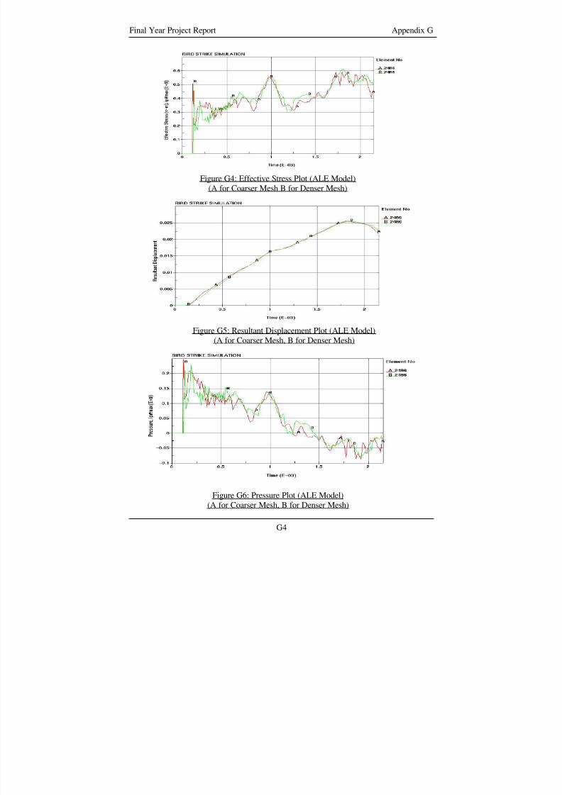
8/3/2019 Fe Analysis of Bird Strikes on Composite and Glass Panels
http://slidepdf.com/reader/full/fe-analysis-of-bird-strikes-on-composite-and-glass-panels 83/89
Final Year Project Report Appendix G
Figure G4: Effective Stress Plot (ALE Model)
(A for Coarser Mesh B for Denser Mesh)
Figure G5: Resultant Displacement Plot (ALE Model)
(A for Coarser Mesh, B for Denser Mesh)
Figure G6: Pressure Plot (ALE Model)
(A for Coarser Mesh, B for Denser Mesh)
G4
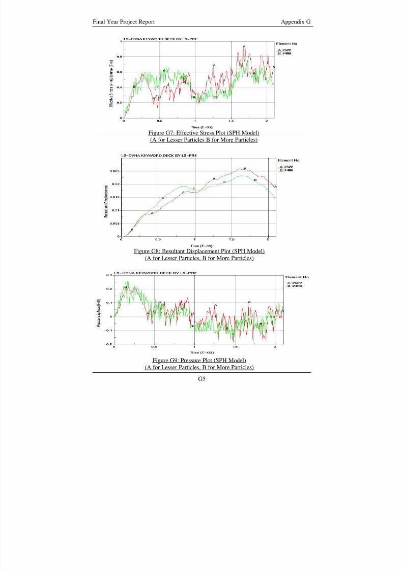
8/3/2019 Fe Analysis of Bird Strikes on Composite and Glass Panels
http://slidepdf.com/reader/full/fe-analysis-of-bird-strikes-on-composite-and-glass-panels 84/89
Final Year Project Report Appendix G
Figure G7: Effective Stress Plot (SPH Model)
(A for Lesser Particles B for More Particles)
Figure G8: Resultant Displacement Plot (SPH Model)
(A for Lesser Particles, B for More Particles)
G5
Figure G9: Pressure Plot (SPH Model)(A for Lesser Particles, B for More Particles)
8/3/2019 Fe Analysis of Bird Strikes on Composite and Glass Panels
http://slidepdf.com/reader/full/fe-analysis-of-bird-strikes-on-composite-and-glass-panels 85/89
Final Year Project Report Appendix H
APPENDIX H – EFFECTIVE STRESS OF
TRANSPARENCIES WITH DIFFERENT
CURVATURE
Effective stress for transparencies of intermediate curvature between radius of curvature
of 0.5m to infinity is plotted. The transparencies of the different curvature can be
identified by the plate number as shown in table 3.7. Figure H1 to H3 shows the effective
stress experienced by the outer, middle and inner layer of the transparencies with
different curvature. Generally the gradual increase or decrease of the effective stress due
to a change in the curvature can be observed.
H1
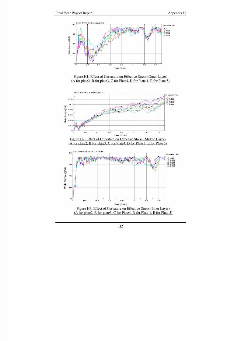
8/3/2019 Fe Analysis of Bird Strikes on Composite and Glass Panels
http://slidepdf.com/reader/full/fe-analysis-of-bird-strikes-on-composite-and-glass-panels 86/89
Final Year Project Report Appendix H
Figure H1: Effect of Curvature on Effective Stress (Outer Layer)
(A for plate2, B for plate3, C for Plate4, D for Plate 1, E for Plate 5)
Figure H2: Effect of Curvature on Effective Stress (Middle Layer)(A for plate2, B for plate3, C for Plate4, D for Plate 1, E for Plate 5)
Figure H3: Effect of Curvature on Effective Stress (Inner Layer)
(A for plate2, B for plate3, C for Plate4, D for Plate 1, E for Plate 5)
H2
8/3/2019 Fe Analysis of Bird Strikes on Composite and Glass Panels
http://slidepdf.com/reader/full/fe-analysis-of-bird-strikes-on-composite-and-glass-panels 87/89
Final Year Project Report References
REFERENCES
1) http://www.birdstrike.org/commlink/birdrisk.htm
2) Sharing the skies – An aviation industry guide to the management of wildlife
hazards. Ottawa, Ontario: Transport Canada, Aviation Publishing Division,
AARA, 2001.
3) http://wildlife.pr.erau.edu/index.html
4) Edward C. Cleary, Richard A. Dolbeer, Sandra E. Wright, Wildlife strike to civil
aircraft in the united states 1990 – 2003; Federal Aviation Administration
National WildLife Strike Database Serial Report Number 10, June 2004
5) Wendy Servoss, Richard M Engeman, Steven Fairaizl, John L Cummings,
N.Paige Groninger, Wildlife hazard assessment for phoenix sky harbor
international airport, International Biodeterioration and Biodegradation 45 (2000)
111 - 127
6) http://www.boeing.com/commercial/safety/whatmakes.html
7) PAM-SHOCKTM /PAM-CRASHTM FE Code, Engineering Systems International,
F-94578 Rungis Cedex, France.
8) LS-DYNA – Theoretical manual. : Livermore Software Technology Corporation,
1998
9) John P. Barber, et al, Characterization of bird impacts on a rigid plate (Part 1),
Dayton University, National Technical Information Service U.S Department of
Commerce, January 1975
R1
8/3/2019 Fe Analysis of Bird Strikes on Composite and Glass Panels
http://slidepdf.com/reader/full/fe-analysis-of-bird-strikes-on-composite-and-glass-panels 88/89
Final Year Project Report References
10) Alastair F. Johnson, Martin Holzapfel, Modeling soft body impact forces on
composite structures, Composite Structures 61 (2003) 103 - 113
11) A. Airoldi, B. Cacchione, Modeling of impact forces and pressures in Lagrangian
bird analysis, International Journal of Impact Engineering, Vol. 32, Issue 10,
1651-1677, Oct 2006
12) B Lagrand, A.s Bayard, Y Chauveau, E Deletombe, Assessment of multi-physics
FE methods for bird strike modeling – Application to a metallic riveted airframe,
International Journal of Crashworthiness 7(4), 2002, 415-428
13) S. C. McCallum, C. Constantinou, Influence of bird-shape in bird strike analysis,
5th European LS-DYNA Users Conference
14) M. A. McCarthy, J. R. Xiao, C. T. McCarthy, A. Kamoulakos, J. Ramos, J. P.
Gallard, V. Melito, Modeling of bird strike on an aircraft wing leading edge made
from fibre metal laminates – Part 2: Modeling of Impact with SPH bird model,
Applied Composite Materials 11: 317 – 340, 2004
15) A.F. Storace, R.P. Nimmer, R. Ravenhall, Analytical and Experimental
investigation of bird impact on fan and compressor blading, Journal of AirCraft,
Vol. 21: 520 – 527, 1998
16) A.G. Hannsen, Y. Girard, L. Olovsson, T. Berstad, M. Langseth, A numerical
model for bird strike of aluminum foam-based sandwich panels, International
Journal of Impact Engineering, Vol. 32, Issue 7, 1127-1144, Jul 2006
17) RADIOSS V4 USER MANUAL, Mecalog Holding, France
18) L. Iannucci, Foreign object impact and energy absorbing structure, CHE Seminar
Publication, 1998
R2
8/3/2019 Fe Analysis of Bird Strikes on Composite and Glass Panels
http://slidepdf.com/reader/full/fe-analysis-of-bird-strikes-on-composite-and-glass-panels 89/89
Final Year Project Report References
19) G.R.Liu, S.S. Quek, The Finite element method, a practical course, 2003
20) TruegridR Manual, Verson 2.0.0 Revision2, XYZ Scientific Applications, Inc,
March 30, 2000
21) F. W. Flocker, L. R. Dharani, Stresses in laminated glass subject to low velocity
impact, Engineering Structures, Vol19, No10, pp.851 – 856, 1997
22) Brent Wright, Benefit of acrylic and composite window for transport aircraft,
Sierracin/Sylmar Corporation
23) http://www.matweb.com/search/GetProperty.asp