Embed Size (px)
DESCRIPTION
HYUNDAI DUCTLESS SPLIT SYSTEMS
Citation preview
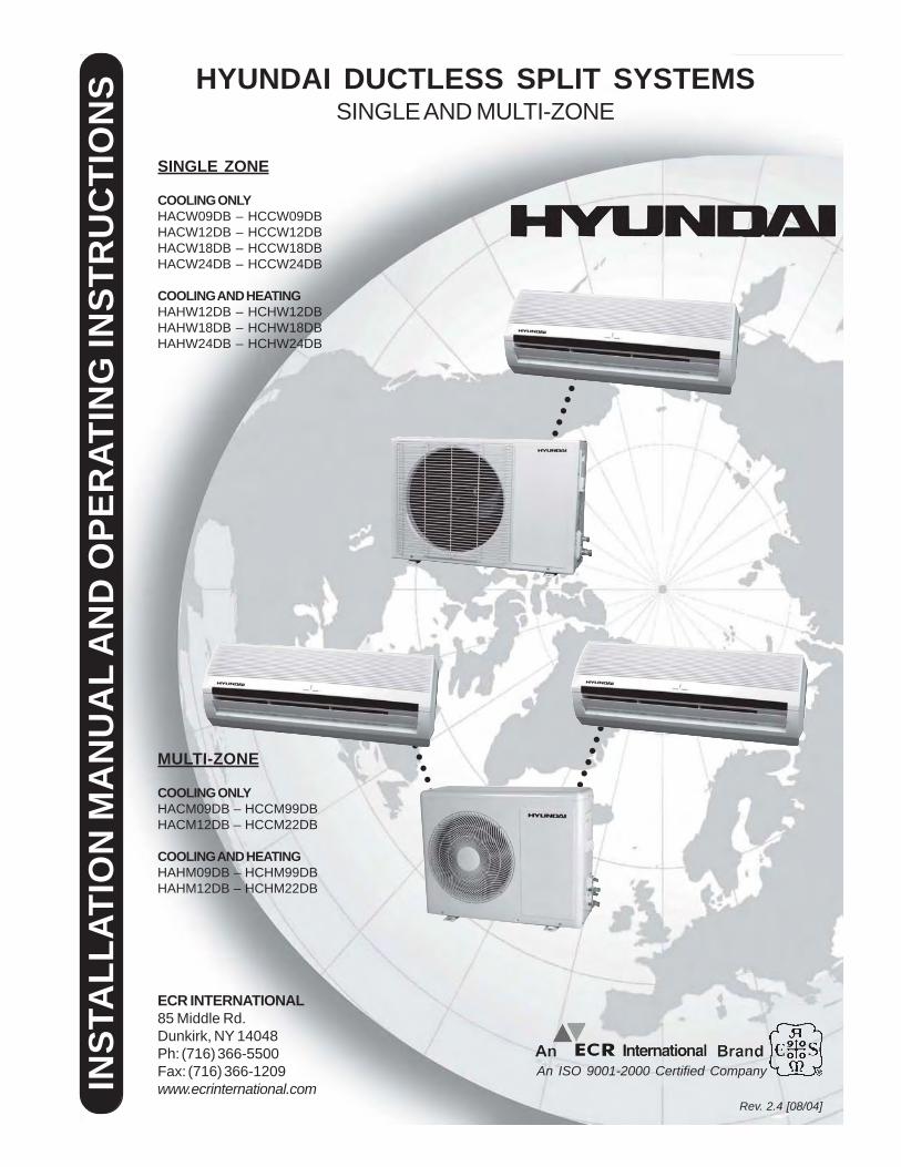
HYUNDAI DUCTLESS SPLIT SYSTEMSSINGLE AND MULTI-ZONE
Rev. 2.4 [08/04]
An ISO 9001-2000 Certified CompanyINST
ALL
ATIO
N M
AN
UA
L A
ND
OPE
RAT
ING
INST
RU
CTI
ON
SSINGLE ZONE
COOLING ONLYHACW09DB – HCCW09DBHACW12DB – HCCW12DBHACW18DB – HCCW18DBHACW24DB – HCCW24DB
COOLING AND HEATINGHAHW12DB – HCHW12DBHAHW18DB – HCHW18DBHAHW24DB – HCHW24DB
MULTI-ZONE
COOLING ONLYHACM09DB – HCCM99DBHACM12DB – HCCM22DB
COOLING AND HEATINGHAHM09DB – HCHM99DBHAHM12DB – HCHM22DB
ECR INTERNATIONAL85 Middle Rd.Dunkirk, NY 14048Ph: (716) 366-5500Fax: (716) 366-1209www.ecrinternational.com
○
○
○
○
○
○
○
○
○
○
○
○
○
○
○
○○
○
○
○
○
○
○
○
ECR International Hyundai Ductless Split System2
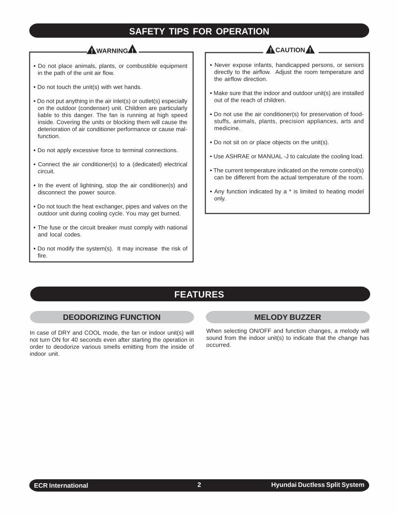
! WARNING !
• Do not place animals, plants, or combustible equipmentin the path of the unit air flow.
• Do not touch the unit(s) with wet hands.
• Do not put anything in the air inlet(s) or outlet(s) especiallyon the outdoor (condenser) unit. Children are particularlyliable to this danger. The fan is running at high speedinside. Covering the units or blocking them will cause thedeterioration of air conditioner performance or cause mal-function.
• Do not apply excessive force to terminal connections.
• Connect the air conditioner(s) to a (dedicated) electricalcircuit.
• In the event of lightning, stop the air conditioner(s) anddisconnect the power source.
• Do not touch the heat exchanger, pipes and valves on theoutdoor unit during cooling cycle. You may get burned.
• The fuse or the circuit breaker must comply with nationaland local codes.
• Do not modify the system(s). It may increase the risk offire.
SAFETY TIPS FOR OPERATION
! CAUTION !
MELODY BUZZERWhen selecting ON/OFF and function changes, a melody willsound from the indoor unit(s) to indicate that the change hasoccurred.
DEODORIZING FUNCTION
In case of DRY and COOL mode, the fan or indoor unit(s) willnot turn ON for 40 seconds even after starting the operation inorder to deodorize various smells emitting from the inside ofindoor unit.
• Never expose infants, handicapped persons, or seniorsdirectly to the airflow. Adjust the room temperature andthe airflow direction.
• Make sure that the indoor and outdoor unit(s) are installedout of the reach of children.
• Do not use the air conditioner(s) for preservation of food-stuffs, animals, plants, precision appliances, arts andmedicine.
• Do not sit on or place objects on the unit(s).
• Use ASHRAE or MANUAL -J to calculate the cooling load.
• The current temperature indicated on the remote control(s)can be different from the actual temperature of the room.
• Any function indicated by a * is limited to heating modelonly.
FEATURES
ECR International Hyundai Ductless Split System3
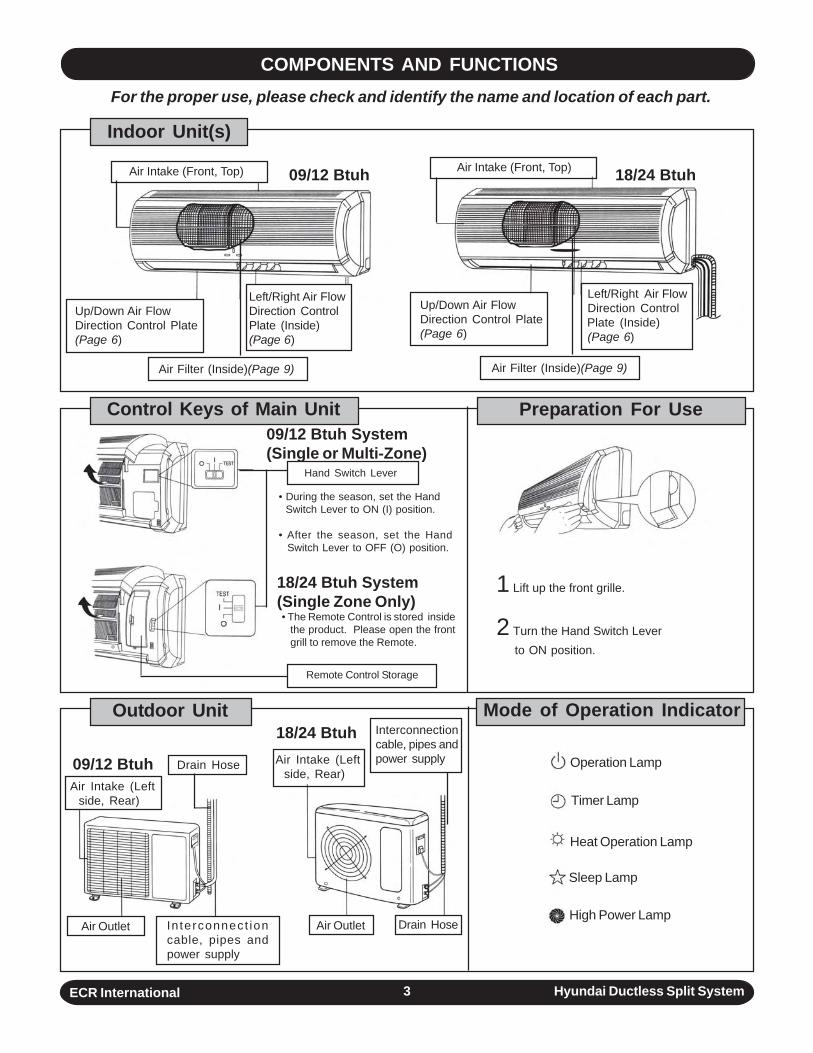
Indoor Unit(s)
Control Keys of Main Unit Preparation For Use
1 Lift up the front grille.
2 Turn the Hand Switch Leverto ON position.
Outdoor Unit Mode of Operation Indicator
Up/Down Air FlowDirection Control Plate(Page 6)
Air Intake (Front, Top)
Left/Right Air FlowDirection ControlPlate (Inside)(Page 6)
Up/Down Air FlowDirection Control Plate(Page 6)
Air Filter (Inside)(Page 9) Air Filter (Inside)(Page 9)
Left/Right Air FlowDirection ControlPlate (Inside)(Page 6)
Air Intake (Front, Top)
• During the season, set the Hand Switch Lever to ON (I) position.
• After the season, set the HandSwitch Lever to OFF (O) position.
Hand Switch Lever
• The Remote Control is stored insidethe product. Please open the frontgrill to remove the Remote.
Remote Control Storage
Air Intake (Leftside, Rear)
Drain Hose
Air Outlet In terconnect ioncable, pipes andpower supply
Air Outlet Drain Hose
Air Intake (Leftside, Rear)
Interconnectioncable, pipes andpower supply
COMPONENTS AND FUNCTIONS For the proper use, please check and identify the name and location of each part.
09/12 Btuh 18/24 Btuh
09/12 Btuh System(Single or Multi-Zone)
18/24 Btuh System(Single Zone Only)
09/12 Btuh
18/24 Btuh
Operation Lamp
Timer Lamp
Heat Operation Lamp
Sleep Lamp
High Power Lamp
ECR International Hyundai Ductless Split System4
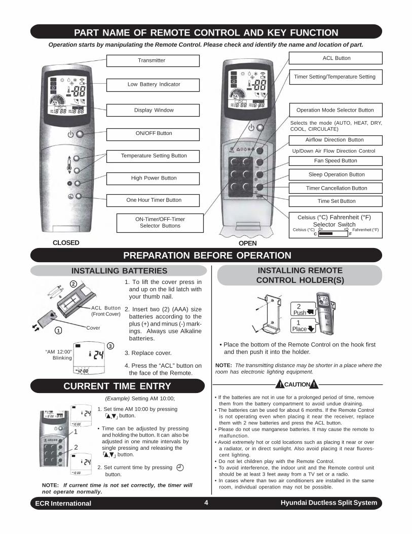
PART NAME OF REMOTE CONTROL AND KEY FUNCTION
1. To lift the cover press inand up on the lid latch withyour thumb nail.
2. Insert two (2) (AAA) sizebatteries according to theplus (+) and minus (-) mark-ings. Always use Alkalinebatteries.
3. Replace cover.
4. Press the “ACL” button onthe face of the Remote.
• When it is attached to the wall.
• Place the bottom of the Remote Control on the hook firstand then push it into the holder.
NOTE: The transmitting distance may be shorter in a place where theroom has electronic lighting equipment.
PREPARATION BEFORE OPERATION
CURRENT TIME ENTRY• If the batteries are not in use for a prolonged period of time, remove
them from the battery compartment to avoid undue draining.• The batteries can be used for about 6 months. If the Remote Control
is not operating even when placing it near the receiver, replacethem with 2 new batteries and press the ACL button.
• Please do not use manganese batteries. It may cause the remote tomalfunction.
• Avoid extremely hot or cold locations such as placing it near or overa radiator, or in direct sunlight. Also avoid placing it near fluores-cent lighting.
• Do not let children play with the Remote Control.• To avoid interference, the indoor unit and the Remote control unit
should be at least 3 feet away from a TV set or a radio.• In cases where than two air conditioners are installed in the same
room, individual operation may not be possible.
Transmitter
Low Battery Indicator
Display Window
ON/OFF Button
Temperature Setting Button
High Power Button
One Hour Timer Button
ON-Timer/OFF-TimerSelector Buttons
ACL Button
Timer Setting/Temperature Setting
Operation Mode Selector Button
Selects the mode (AUTO, HEAT, DRY,COOL, CIRCULATE)
Airflow Direction Button
Fan Speed Button
Sleep Operation Button
Timer Cancellation Button
Time Set Button
Celsius (°C) Fahrenheit (°F)Selector Switch
Celsius (°C) Fahrenheit (°F)C F
Up/Down Air Flow Direction Control
ACL Button(Front Cover)
Cover
“AM 12:00”Blinking
1
2
3
INSTALLING REMOTECONTROL HOLDER(S)
INSTALLING BATTERIES
! CAUTION !
2 Push
1 Place
(Example) Setting AM 10:00;
OPENCLOSED
1. Set time AM 10:00 by pressing button.
• Time can be adjusted by pressingand holding the button. It can also beadjusted in one minute intervals bysingle pressing and releasing the
button.
2. Set current time by pressing button.
1
2
NOTE: If current time is not set correctly, the timer willnot operate normally.
Operation starts by manipulating the Remote Control. Please check and identify the name and location of part.
ECR International Hyundai Ductless Split System5
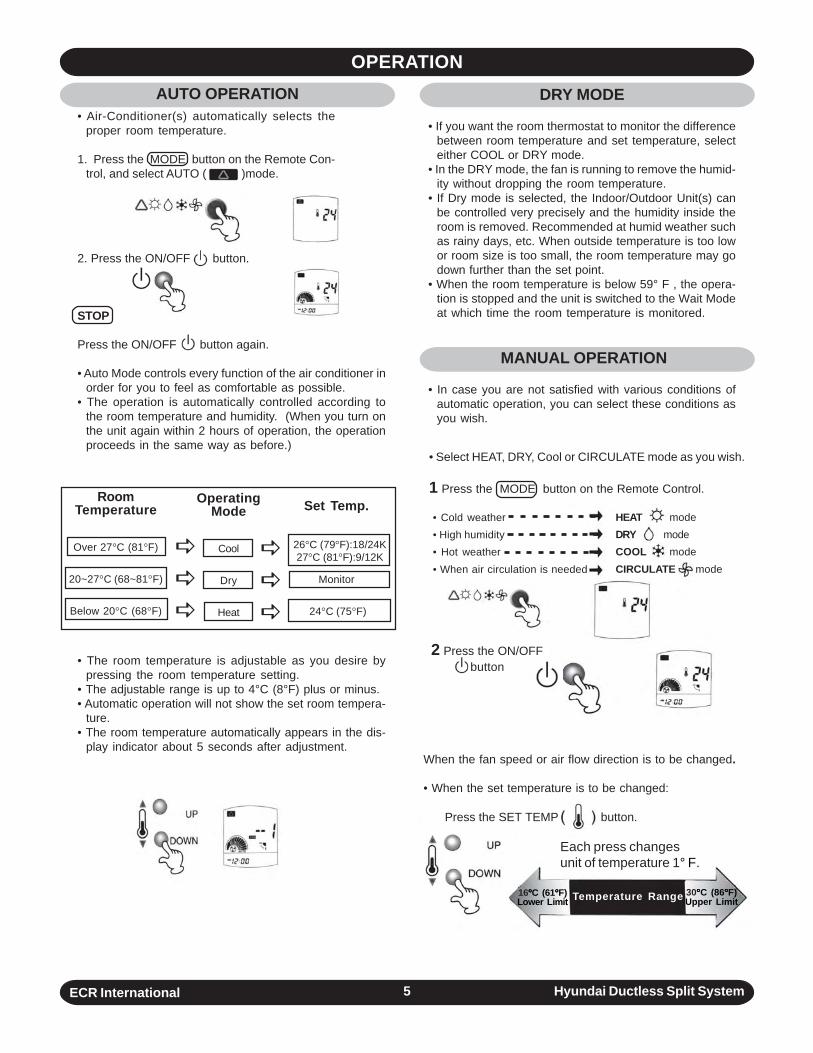
OPERATIONDRY MODE
• If you want the room thermostat to monitor the differencebetween room temperature and set temperature, selecteither COOL or DRY mode.
• In the DRY mode, the fan is running to remove the humid-ity without dropping the room temperature.
• If Dry mode is selected, the Indoor/Outdoor Unit(s) canbe controlled very precisely and the humidity inside theroom is removed. Recommended at humid weather suchas rainy days, etc. When outside temperature is too lowor room size is too small, the room temperature may godown further than the set point.
• When the room temperature is below 59° F , the opera-tion is stopped and the unit is switched to the Wait Modeat which time the room temperature is monitored.
MANUAL OPERATION
• In case you are not satisfied with various conditions ofautomatic operation, you can select these conditions asyou wish.
• Air-Conditioner(s) automatically selects theproper room temperature.
1. Press the MODE button on the Remote Con-trol, and select AUTO ( )mode.
• Select HEAT, DRY, Cool or CIRCULATE mode as you wish.
1 Press the MODE button on the Remote Control.
• Cold weather• High humidity• Hot weather• When air circulation is needed
HEAT modeDRY modeCOOL modeCIRCULATE mode
2 Press the ON/OFFbutton
When the fan speed or air flow direction is to be changed.
• When the set temperature is to be changed:
RoomTemperature
Over 27°C (81°F)
20~27°C (68~81°F)
Below 20°C (68°F)
OperatingMode
Cool
Dry
Heat
Set Temp.
Monitor
24°C (75°F)
26°C (79°F):18/24K 27°C (81°F):9/12K
2. Press the ON/OFF button.
STOP
Press the ON/OFF button again.
• Auto Mode controls every function of the air conditioner inorder for you to feel as comfortable as possible.
• The operation is automatically controlled according tothe room temperature and humidity. (When you turn onthe unit again within 2 hours of operation, the operationproceeds in the same way as before.)
• The room temperature is adjustable as you desire bypressing the room temperature setting.
• The adjustable range is up to 4°C (8°F) plus or minus.• Automatic operation will not show the set room tempera-
ture.• The room temperature automatically appears in the dis-
play indicator about 5 seconds after adjustment.
Temperature Range16°°°°°C (61°°°°°F)Lower Limit
30°°°°°C (86°°°°°F)Upper Limit
Each press changesunit of temperature 1° F.
Press the SET TEMP button.
AUTO OPERATION
ECR International Hyundai Ductless Split System6
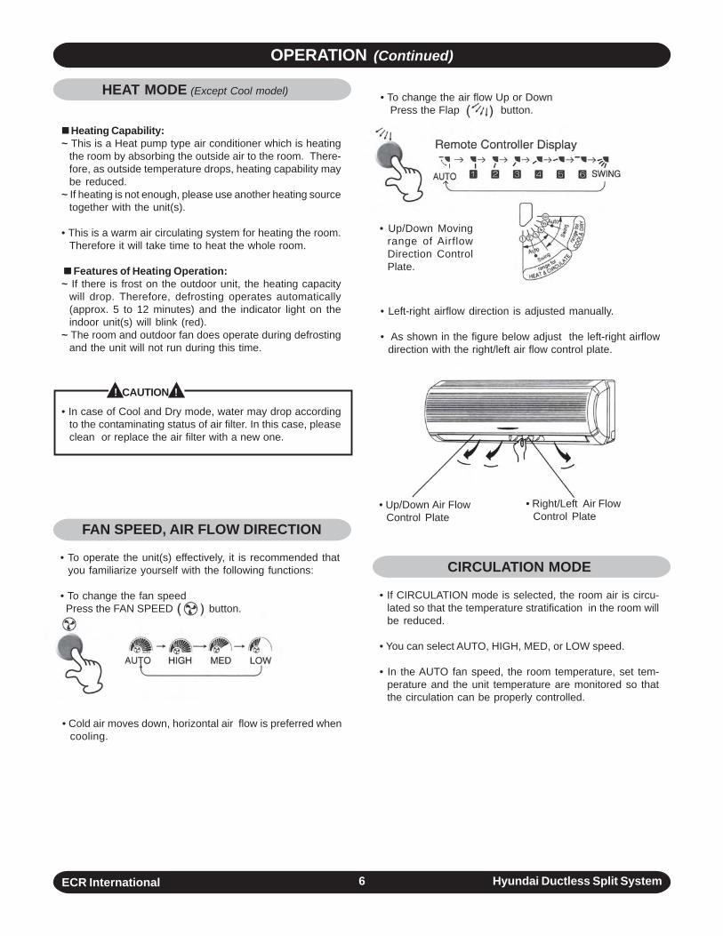
HEAT MODE (Except Cool model)
Heating Capability:~ This is a Heat pump type air conditioner which is heating
the room by absorbing the outside air to the room. There-fore, as outside temperature drops, heating capability maybe reduced.
~ If heating is not enough, please use another heating sourcetogether with the unit(s).
• This is a warm air circulating system for heating the room.Therefore it will take time to heat the whole room.
Features of Heating Operation:~ If there is frost on the outdoor unit, the heating capacity
will drop. Therefore, defrosting operates automatically(approx. 5 to 12 minutes) and the indicator light on theindoor unit(s) will blink (red).
~ The room and outdoor fan does operate during defrostingand the unit will not run during this time.
• In case of Cool and Dry mode, water may drop accordingto the contaminating status of air filter. In this case, pleaseclean or replace the air filter with a new one.
OPERATION (Continued)
FAN SPEED, AIR FLOW DIRECTION
• To operate the unit(s) effectively, it is recommended thatyou familiarize yourself with the following functions:
• To change the fan speed Press the FAN SPEED button.
• Cold air moves down, horizontal air flow is preferred whencooling.
• To change the air flow Up or Down Press the Flap button.
• Up/Down Movingrange of AirflowDirection ControlPlate.
• Left-right airflow direction is adjusted manually.
• As shown in the figure below adjust the left-right airflowdirection with the right/left air flow control plate.
CIRCULATION MODE
• If CIRCULATION mode is selected, the room air is circu-lated so that the temperature stratification in the room willbe reduced.
• You can select AUTO, HIGH, MED, or LOW speed.
• In the AUTO fan speed, the room temperature, set tem-perature and the unit temperature are monitored so thatthe circulation can be properly controlled.
• Up/Down Air FlowControl Plate
• Right/Left Air FlowControl Plate
! CAUTION !
ECR International Hyundai Ductless Split System7
mark will blink
mark will blink
OPERATION (Continued)
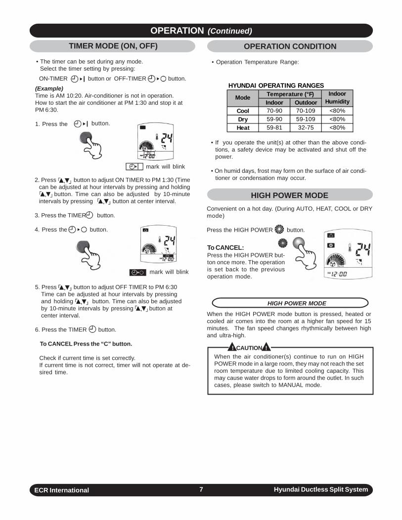
(Example)Time is AM 10:20. Air-conditioner is not in operation.How to start the air conditioner at PM 1:30 and stop it atPM 6:30.
1. Press the button.
ON-TIMER button or OFF-TIMER button.
2. Press button to adjust ON TIMER to PM 1:30 (Timecan be adjusted at hour intervals by pressing and holding
button. Time can also be adjusted by 10-minuteintervals by pressing button at center interval.
3. Press the TIMER button.
4. Press the button.
5. Press button to adjust OFF TIMER to PM 6:30Time can be adjusted at hour intervals by pressingand holding button. Time can also be adjustedby 10-minute intervals by pressing button atcenter interval.
6. Press the TIMER button.
To CANCEL Press the “C” button.
Check if current time is set correctly.If current time is not correct, timer will not operate at de-sired time.
HIGH POWER MODE
When the HIGH POWER mode button is pressed, heated orcooled air comes into the room at a higher fan speed for 15minutes. The fan speed changes rhythmically between highand ultra-high.
When the air conditioner(s) continue to run on HIGHPOWER mode in a large room, they may not reach the setroom temperature due to limited cooling capacity. Thismay cause water drops to form around the outlet. In suchcases, please switch to MANUAL mode.
To CANCEL:Press the HIGH POWER but-ton once more. The operationis set back to the previousoperation mode.
• If you operate the unit(s) at other than the above condi-tions, a safety device may be activated and shut off thepower.
• On humid days, frost may form on the surface of air condi-tioner or condensation may occur.
HIGH POWER MODEConvenient on a hot day. (During AUTO, HEAT, COOL or DRYmode)
Press the HIGH POWER button.
OPERATION CONDITION
• Operation Temperature Range:
TIMER MODE (ON, OFF)
• The timer can be set during any mode. Select the timer setting by pressing:
! CAUTION !
HYUNDAI OPERATING RANGES
Indoor OutdoorCool 70-90 70-109 <80%Dry 59-90 59-109 <80%Heat 59-81 32-75 <80%
Temperature (°F) Indoor HumidityMode
ECR International Hyundai Ductless Split System8
OPERATION (Continued)
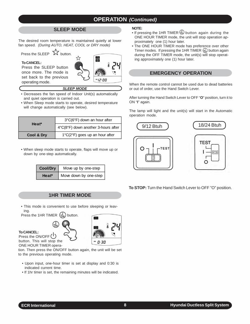
SLEEP MODE• Decreases the fan speed of Indoor Unit(s) automatically
and quiet operation is carried out.• When Sleep mode starts to operate, desired temperature
will change automatically (see below).
To CANCEL:Press the SLEEP buttononce more. The mode isset back to the previousoperating mode.
• When sleep mode starts to operate, flaps will move up ordown by one-step automatically.
3°C(6°F) down an hour after
4°C(8°F) down another 3-hours after
Cool & Dry 1°C(2°F) goes up an hour after
Heat*
Cool/Dry Move up by one-step
Heat* Move down by one-step
• Upon input, one-hour timer is set at display and 0:30 isindicated current time.
• If 1hr timer is set, the remaining minutes will be indicated.
To STOP: Turn the Hand Switch Lever to OFF ”O” position.
NOTE:• If pressing the 1HR TIMER button again during the
ONE HOUR TIMER mode, the unit will stop operation ap-proximately one (1) hour later.
• The ONE HOUR TIMER mode has preference over otherTimer modes. If pressing the 1HR TIMER button againduring the OFF TIMER mode, the unit(s) will stop operat-ing approximately one (1) hour later.
EMERGENCY OPERATION
When the remote control cannot be used due to dead batteriesor out of order, use the Hand Switch Lever.
After turning the Hand Switch Lever to OFF “O” position, turn it toON “I” again.
The lamp will light and the unit(s) will start in the Automaticoperation mode.
SLEEP MODE
The desired room temperature is maintained quietly at lowerfan speed. (During AUTO, HEAT, COOL or DRY mode)
Press the SLEEP button.
To CANCEL:Press the ON/OFFbutton. This will stop theONE HOUR TIMER opera-tion. Then press the ON/OFF button again, the unit will be setto the previous operating mode.
1HR TIMER MODE
• This mode is convenient to use before sleeping or leav-ing.
Press the 1HR TIMER button.
9/12 Btuh 18/24 Btuh
ECR International Hyundai Ductless Split System9
OPERATION MODE (Continued)
MAINTENANCE
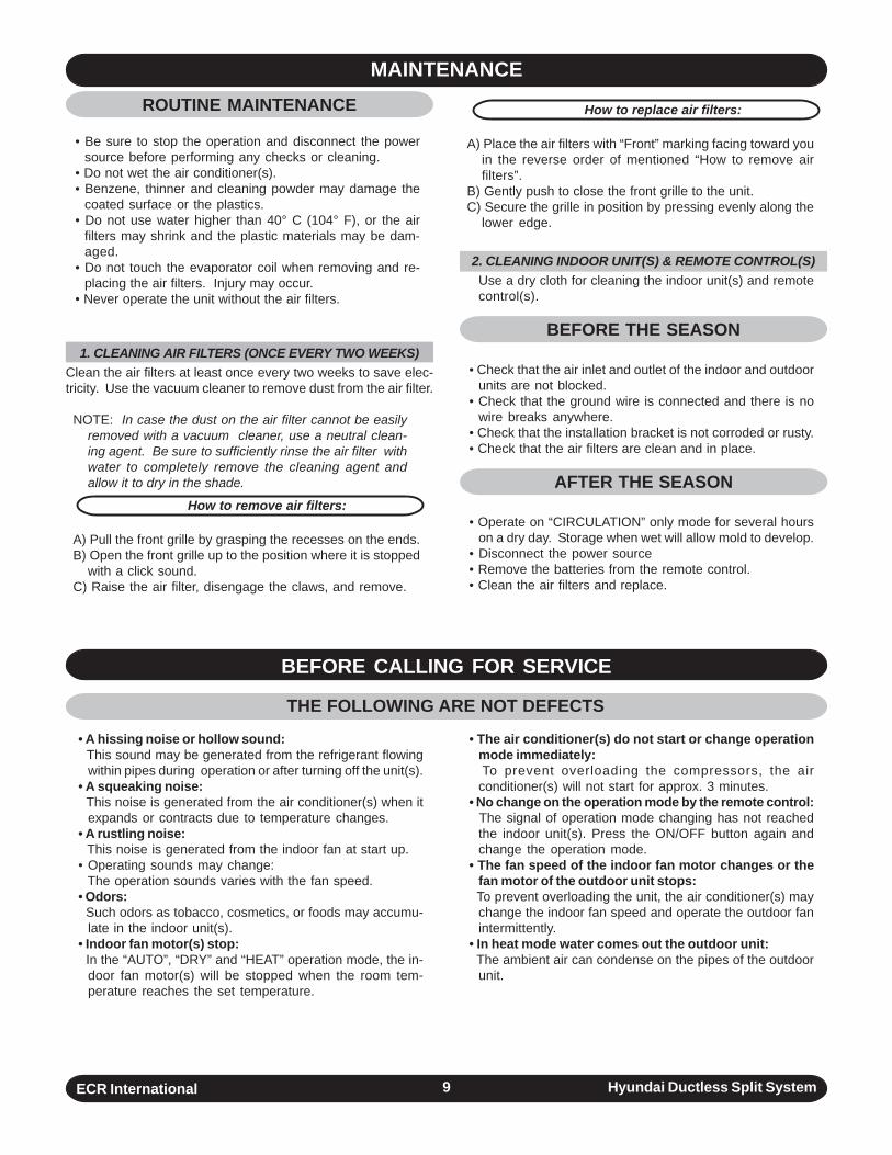
• A hissing noise or hollow sound: This sound may be generated from the refrigerant flowing
within pipes during operation or after turning off the unit(s).• A squeaking noise: This noise is generated from the air conditioner(s) when it
expands or contracts due to temperature changes.• A rustling noise: This noise is generated from the indoor fan at start up.• Operating sounds may change: The operation sounds varies with the fan speed.• Odors: Such odors as tobacco, cosmetics, or foods may accumu-
late in the indoor unit(s).• Indoor fan motor(s) stop: In the “AUTO”, “DRY” and “HEAT” operation mode, the in-
door fan motor(s) will be stopped when the room tem-perature reaches the set temperature.
BEFORE CALLING FOR SERVICE
• The air conditioner(s) do not start or change operationmode immediately:
To prevent overloading the compressors, the airconditioner(s) will not start for approx. 3 minutes.
• No change on the operation mode by the remote control: The signal of operation mode changing has not reached
the indoor unit(s). Press the ON/OFF button again andchange the operation mode.
• The fan speed of the indoor fan motor changes or thefan motor of the outdoor unit stops:
To prevent overloading the unit, the air conditioner(s) maychange the indoor fan speed and operate the outdoor fanintermittently.
• In heat mode water comes out the outdoor unit: The ambient air can condense on the pipes of the outdoor
unit.
THE FOLLOWING ARE NOT DEFECTS
ROUTINE MAINTENANCE
• Be sure to stop the operation and disconnect the powersource before performing any checks or cleaning.
• Do not wet the air conditioner(s).• Benzene, thinner and cleaning powder may damage the
coated surface or the plastics.• Do not use water higher than 40° C (104° F), or the air
filters may shrink and the plastic materials may be dam-aged.
• Do not touch the evaporator coil when removing and re-placing the air filters. Injury may occur.
• Never operate the unit without the air filters.
1. CLEANING AIR FILTERS (ONCE EVERY TWO WEEKS)Clean the air filters at least once every two weeks to save elec-tricity. Use the vacuum cleaner to remove dust from the air filter.
NOTE: In case the dust on the air filter cannot be easilyremoved with a vacuum cleaner, use a neutral clean-ing agent. Be sure to sufficiently rinse the air filter withwater to completely remove the cleaning agent andallow it to dry in the shade.
How to remove air filters:
A) Pull the front grille by grasping the recesses on the ends.B) Open the front grille up to the position where it is stopped
with a click sound.C) Raise the air filter, disengage the claws, and remove.
How to replace air filters:
A) Place the air filters with “Front” marking facing toward youin the reverse order of mentioned “How to remove airfilters”.
B) Gently push to close the front grille to the unit.C) Secure the grille in position by pressing evenly along the
lower edge.
2. CLEANING INDOOR UNIT(S) & REMOTE CONTROL(S)Use a dry cloth for cleaning the indoor unit(s) and remotecontrol(s).
BEFORE THE SEASON
• Check that the air inlet and outlet of the indoor and outdoorunits are not blocked.
• Check that the ground wire is connected and there is nowire breaks anywhere.
• Check that the installation bracket is not corroded or rusty.• Check that the air filters are clean and in place.
AFTER THE SEASON
• Operate on “CIRCULATION” only mode for several hourson a dry day. Storage when wet will allow mold to develop.
• Disconnect the power source• Remove the batteries from the remote control.• Clean the air filters and replace.
ECR International Hyundai Ductless Split System10
BEFORE CALLING FOR SERVICE (Continued)
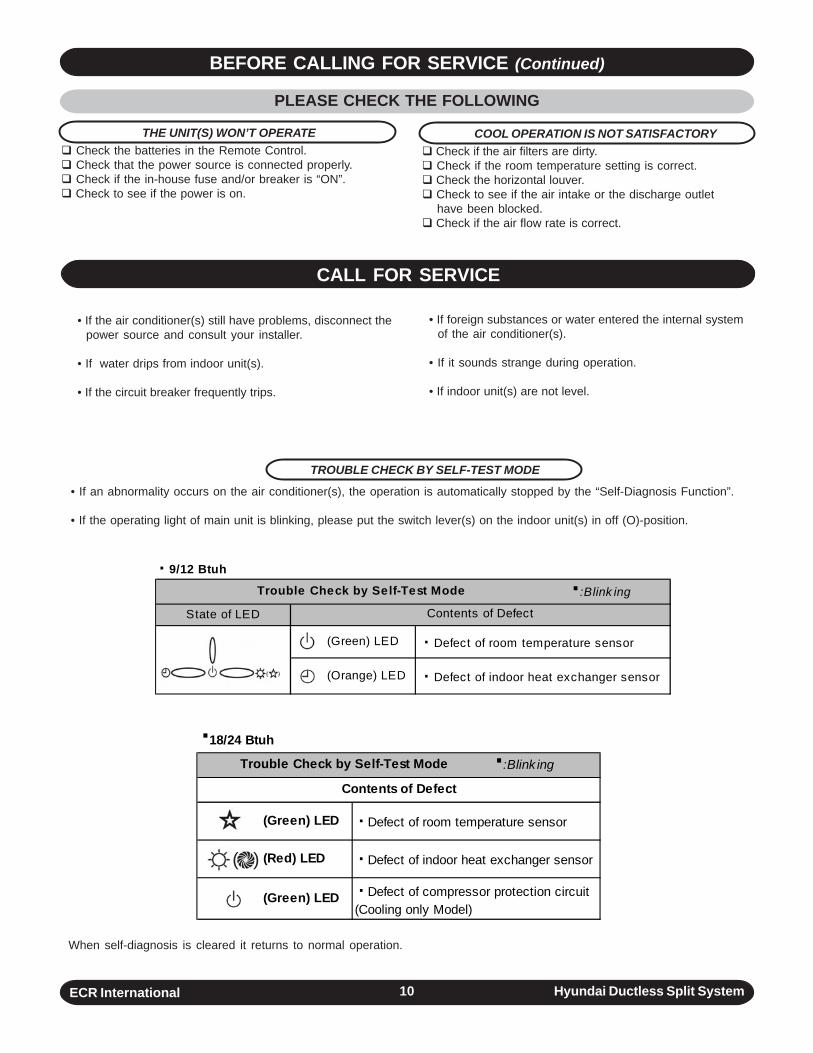
• If the air conditioner(s) still have problems, disconnect thepower source and consult your installer.
• If water drips from indoor unit(s).
• If the circuit breaker frequently trips.
When self-diagnosis is cleared it returns to normal operation.
CALL FOR SERVICE
· 9/12 Btuh
·:Blink ing
State of LED
(Green) LED
(Orange) LED
Trouble Check by Self-Test Mode
· Defect of indoor heat exchanger sensor
Contents of Defect
· Defect of room temperature sensor
TROUBLE CHECK BY SELF-TEST MODE
• If an abnormality occurs on the air conditioner(s), the operation is automatically stopped by the “Self-Diagnosis Function”.
• If the operating light of main unit is blinking, please put the switch lever(s) on the indoor unit(s) in off (O)-position.
·18/24 Btuh
·:Blink ing
(Green) LED
(Red) LED
(Green) LED
· Defect of indoor heat exchanger sensor
· Defect of compressor protection circuit (Cooling only Model)
Trouble Check by Self-Test Mode
Contents of Defect
· Defect of room temperature sensor
( )
PLEASE CHECK THE FOLLOWING
THE UNIT(S) WON’T OPERATE Check the batteries in the Remote Control. Check that the power source is connected properly. Check if the in-house fuse and/or breaker is “ON”. Check to see if the power is on.
COOL OPERATION IS NOT SATISFACTORY Check if the air filters are dirty. Check if the room temperature setting is correct. Check the horizontal louver. Check to see if the air intake or the discharge outlethave been blocked.
Check if the air flow rate is correct.
• If foreign substances or water entered the internal systemof the air conditioner(s).
• If it sounds strange during operation.
• If indoor unit(s) are not level.
ECR International Hyundai Ductless Split System11
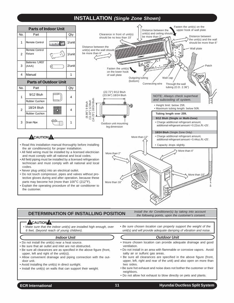
INSTALLATION (Single Zone Shown)
• Make sure that the indoor unit(s) are installed high enough, over6 feet, (beyond reach of young children).
Indoor Unit• Do not install the unit(s) near a heat source.• Be sure that air outlet and inlet are not obstructed.• Be sure all clearances are as specified in the above figure (front,
upper, left and right of the unit(s)).• Allow convenient drainage and piping connection with the out-
door unit.• Avoid installing the unit(s) in direct sunlight.• Install the unit(s) on walls that can support their weight.
! CAUTION !
• Read this installation manual thoroughly before installingthe air conditioner(s) for proper installation.
• All field wiring must be installed by a licensed electricianand must comply with all national and local codes.
• All field piping must be installed by a licensed refrigerationtechnician and must comply with all national and localcodes.
• Never plug unit(s) into an electrical outlet.• Do not touch compressor, pipes and valves without pro-
tective gloves during and after operation, because theseparts may become hot (more than 100°C (212°F).
• Explain the operating procedure of the air conditioner tothe customer.
! CAUTION !
DETERMINATION OF INSTALLING POSITION Install the Air Conditioner(s) by taking into accountthe following points, upon the customer’s consent.
No. Part Qty
1 Remote Control 1/unit
2Remote Control Fixture 1/unit
3Batteries 'LR03' (AAA) 2/unit
4 Manual 1
No. Part Qty
9/12 Btuh
Rubber Cushion
18/24 Btuh
Rubber Cushion
3 Drain Pipe 1
1
2
Parts of Indoor Unit
Parts of Outdoor Unit
4
4
• Be sure chosen location can properly support the weight of theunit(s) and will provide adequate damping of vibration and noise.
Outdoor Unit• Insure chosen location can provide adequate drainage and good
ventilation.• Do not install in an area with flammable or corrosive vapors. Avoid
salty air or sulfuric gas areas.• Be sure all clearances are specified in the above figure (front,
upper, left, right and rear of the unit) and also open on more thantwo sides.
• Be sure hot exhaust and noise does not bother the customer or theirneighbors.
• Do not allow hot exhaust to blow directly on pets and plants.
NOTE: Always check superheatand subcooling of system.
(22.72”) 9/12 Btuh(23.94”) 18/24 Btuh
(8.8
6”) 9
Btu
h(1
1.02
”) 1
2 B
tuh
(14.
25”)
18/
24 B
tuh
Outdoor unit mountingleg dimension
Distance between theunit(s) and ceiling shouldbe more than 2”
Clearance in front of unit(s)should be no less than 10’
Distance between theunit(s) and the wall shouldbe more than 6”
Fasten the unit(s)on the lower hookof wall plate
Fasten the unit(s) on the upper hook of wall plate
Distance betweenthe unit(s) and the wallshould be more than 6”
Wall plate
Patch
Outgoing tubing(bottom)
Wall cap
Connecting wire Through the walltubing (O.D. 2.36”)
• Height limit: below 25ft.• Maximum tubing length: below 50ft.
Tubing length over 25ft.9/12 Btuh (Single or Multi-Zone)• Charge additional refrigerant amount,
additional refrigerant amount =0.22oz./ft.>25’.
18/24 Btuh (Single Zone Only)• Charge additional refrigerant amount,
additional refrigerant amount =0.44oz./ft.>25’.
• Capacity drops slightly.
More than 12”
More than 2”
More than 16”
More than 4”
More than 10”
ECR International Hyundai Ductless Split System12
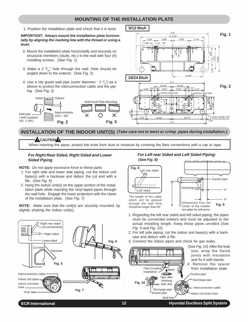
For Right Rear Sided, Right Sided and LowerSided Piping
NOTE: Do not apply excessive force to these parts.1. For right side and lower side piping, cut the indoor unit
base(s) with a hacksaw and deburr the cut end with afile. (See Fig. 5)
2. Hang the indoor unit(s) on the upper portion of the instal-lation plate while inserting the vinyl-taped pipes throughthe wall hole. Engage the lower projection with the clawsof the installation plate. (See Fig. 7)
NOTE: Make sure that the unit(s) are securely mounted, byslightly shaking the indoor unit(s).
The length of the cablewhich will be passedthrough the wall holeshould be longer than 40”.
1. Regarding the left rear sided and left sided piping, the pipesmust be connected indoors and must be adjusted to theactual installing length. Keep these pipes unrolled (SeeFig. 9 and Fig. 10)
2. For left side piping, cut the indoor unit base(s) with a hack-saw and deburr with a file.
3. Connect the indoor pipes and check for gas leaks.
MOUNTING OF THE INSTALLATION PLATE
INSTALLATION OF THE INDOOR UNIT(S)! CAUTION !
For Left rear Sided and Left Sided Piping: (See Fig. 8)
1. Position the installation plate and check that it is level.
IMPORTANT: Always mount the installation plate horizon-tally by aligning the marking line with the thread or using alevel.
2. Mount the installation plate horizontally and securely onstructural members (studs, etc.) in the wall with four (4)installing screws. (See Fig. 1)
3. Make a 2 9/16” hole through the wall. Hole should beangled down to the exterior. (See Fig. 2)
4. Use a city grade wall pipe (outer diameter : 2 3/8”) as asleeve to protect the interconnection cable and the pip-ing. (See Fig. 2)
When inserting the pipes, protect the ends from dust or moisture by covering the flare connections with a cap or tape.
(Take care not to twist or crimp pipes during installation.)
Fig. 1
Fig. 2
18/24 Btuh
9/12 Btuh
Pipe hole Ø 2.56”1.93”
Anchor plug holeAnchor plug hole
3’ 4”
18.74”5.04”
3’ 2”10.33” 10.33”
15.63”
8.52” 8.52” 6.63”6.63” 1.81” 1.81”1.81” 1.81”
1.40
”
3.93
”
2.92
”
4.31
”3.
72”
3.93
”7.
44”
9.84
”
3.43
”
4.21
”
1.18
”5.
53”
9.12
”10
.83”
2’ 6”2’ 2.25”
5.28” 6.89” 6.89” 5.79”1.38” .85”
12.60”
Fig. 8Left rear sided
Left sided
Fig. 9
Suction pipe
Discharge pipe
Dimensions from thecenter of the installa-tion plate for reference.
4”
6”
Fig. 2 Fig. 3
Wall pipe( field suppliedOD: 2 3/8”)
Wall-Hook Plate Mounting
Approximately3/16”– 3/8”
Indoor Outdoor
Flare Couplinginstallation
Band
Tape afterfinishingleak test
Discharge pipeSuction pipe
Suction pipe
Discharge pipe
Interconnection cable
Indoor unit drain hoseWall hole
Fig. 10
(See Fig. 10) After the leaktest, wrap the flaredjoints with insulationand fix it with bands.
4. Remove the spacerfrom installation plate.
Fig. 4
Fig. 5
Fig. 6
Fig. 7
Right rear sided (recommended)
Right sided
Lower sided
Cut hereHacksaw
Interconnection cable
Indoor unit pipesIndoor unit drainhose
Vinyl tape
ECR International Hyundai Ductless Split System13
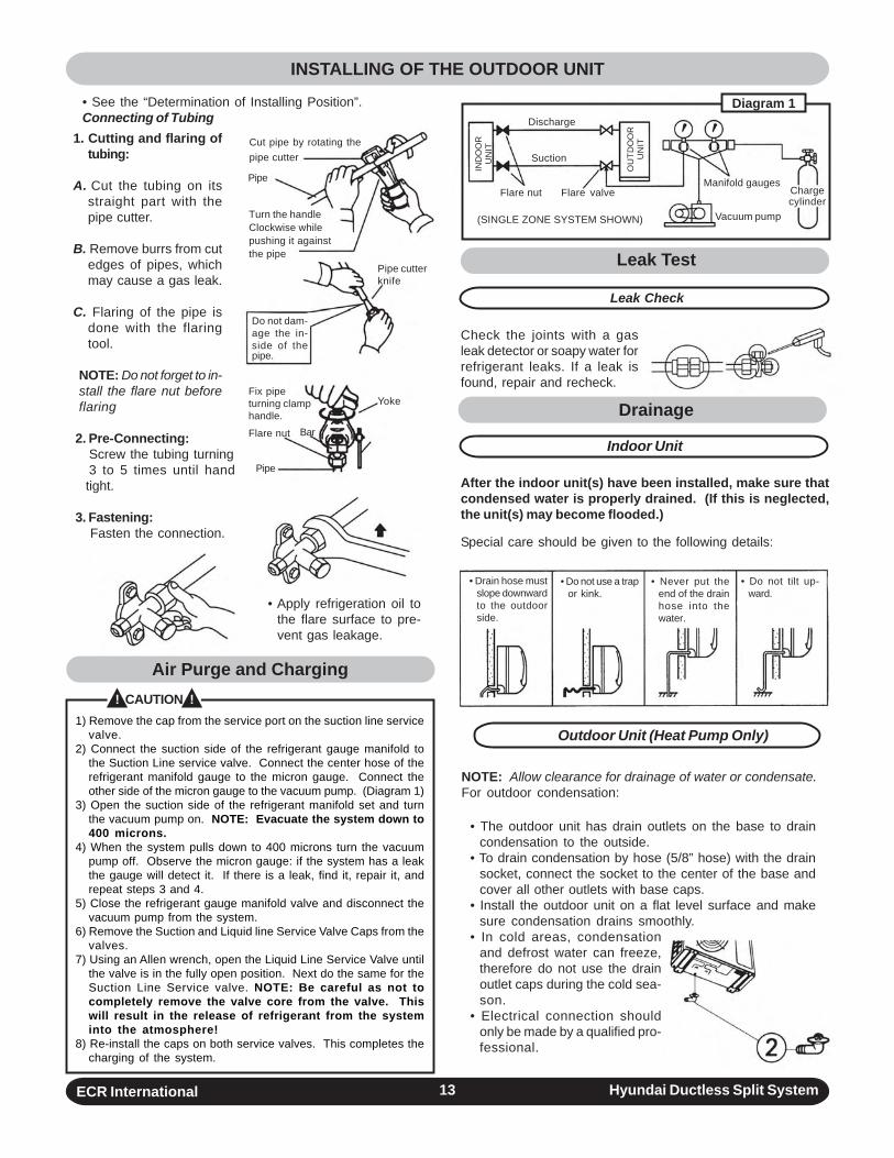
1. Cutting and flaring oftubing:
A. Cut the tubing on itsstraight part with thepipe cutter.
B. Remove burrs from cutedges of pipes, whichmay cause a gas leak.
C. Flaring of the pipe isdone with the flaringtool.
NOTE: Do not forget to in-stall the flare nut beforeflaring
2. Pre-Connecting:Screw the tubing turning3 to 5 times until handtight.
3. Fastening: Fasten the connection.
• Apply refrigeration oil tothe flare surface to pre-vent gas leakage.
Leak Test
Leak Check
Check the joints with a gasleak detector or soapy water forrefrigerant leaks. If a leak isfound, repair and recheck.
Drainage
Indoor Unit
After the indoor unit(s) have been installed, make sure thatcondensed water is properly drained. (If this is neglected,the unit(s) may become flooded.)
Special care should be given to the following details:
Outdoor Unit (Heat Pump Only)
NOTE: Allow clearance for drainage of water or condensate.For outdoor condensation:
• The outdoor unit has drain outlets on the base to draincondensation to the outside.
• To drain condensation by hose (5/8” hose) with the drainsocket, connect the socket to the center of the base andcover all other outlets with base caps.
• Install the outdoor unit on a flat level surface and makesure condensation drains smoothly.
• In cold areas, condensationand defrost water can freeze,therefore do not use the drainoutlet caps during the cold sea-son.
• Electrical connection shouldonly be made by a qualified pro-fessional.
• See the “Determination of Installing Position”.Connecting of Tubing
INSTALLING OF THE OUTDOOR UNIT
1) Remove the cap from the service port on the suction line servicevalve.
2) Connect the suction side of the refrigerant gauge manifold tothe Suction Line service valve. Connect the center hose of therefrigerant manifold gauge to the micron gauge. Connect theother side of the micron gauge to the vacuum pump. (Diagram 1)
3) Open the suction side of the refrigerant manifold set and turnthe vacuum pump on. NOTE: Evacuate the system down to400 microns.
4) When the system pulls down to 400 microns turn the vacuumpump off. Observe the micron gauge: if the system has a leakthe gauge will detect it. If there is a leak, find it, repair it, andrepeat steps 3 and 4.
5) Close the refrigerant gauge manifold valve and disconnect thevacuum pump from the system.
6) Remove the Suction and Liquid line Service Valve Caps from thevalves.
7) Using an Allen wrench, open the Liquid Line Service Valve untilthe valve is in the fully open position. Next do the same for theSuction Line Service valve. NOTE: Be careful as not tocompletely remove the valve core from the valve. Thiswill result in the release of refrigerant from the systeminto the atmosphere!
8) Re-install the caps on both service valves. This completes thecharging of the system.
! CAUTION !
Cut pipe by rotating thepipe cutter
Pipe
Turn the handleClockwise whilepushing it againstthe pipe
Pipe cutterknife
Yoke
Do not dam-age the in-side of thepipe.
BarFlare nut
Fix pipeturning clamphandle.
Pipe
• Drain hose mustslope downwardto the outdoorside.
• Do not use a trapor kink.
• Never put theend of the drainhose into thewater.
• Do not tilt up-ward.
Flare nut Flare valveManifold gauges
Chargecylinder
Discharge
Suction
Vacuum pump
IND
OO
RU
NIT
OU
TDO
OR
UN
IT
Diagram 1
Air Purge and Charging
(SINGLE ZONE SYSTEM SHOWN)
ECR International Hyundai Ductless Split System14
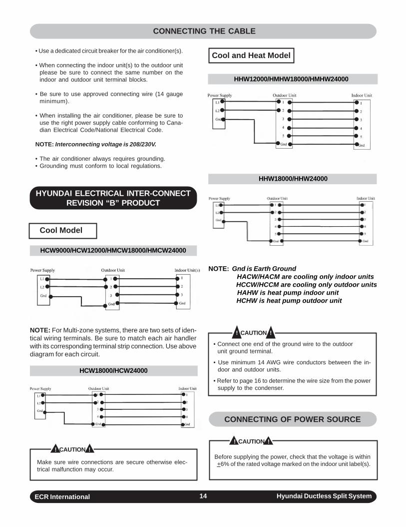
• Use a dedicated circuit breaker for the air conditioner(s).
• When connecting the indoor unit(s) to the outdoor unitplease be sure to connect the same number on theindoor and outdoor unit terminal blocks.
• Be sure to use approved connecting wire (14 gaugeminimum).
• When installing the air conditioner, please be sure touse the right power supply cable conforming to Cana-dian Electrical Code/National Electrical Code.
NOTE: Interconnecting voltage is 208/230V.
• The air conditioner always requires grounding.• Grounding must conform to local regulations.
CONNECTING THE CABLE
! CAUTION !
CONNECTING OF POWER SOURCE
Before supplying the power, check that the voltage is within+6% of the rated voltage marked on the indoor unit label(s).
• Connect one end of the ground wire to the outdoor unit ground terminal.
• Use minimum 14 AWG wire conductors between the in-door and outdoor units.
• Refer to page 16 to determine the wire size from the powersupply to the condenser.
! CAUTION !
Make sure wire connections are secure otherwise elec-trical malfunction may occur.
Cool and Heat Model
HYUNDAI ELECTRICAL INTER-CONNECTREVISION “B” PRODUCT
Cool Model
HHW18000/HHW24000
NOTE: Gnd is Earth Ground HACW/HACM are cooling only indoor units HCCW/HCCM are cooling only outdoor units HAHW is heat pump indoor unit HCHW is heat pump outdoor unit
! CAUTION !NOTE: For Multi-zone systems, there are two sets of iden-tical wiring terminals. Be sure to match each air handlerwith its corresponding terminal strip connection. Use abovediagram for each circuit.
HCW9000/HCW12000/HMCW18000/HMCW24000
HHW12000/HMHW18000/HMHW24000
HCW18000/HCW24000
ECR International Hyundai Ductless Split System15
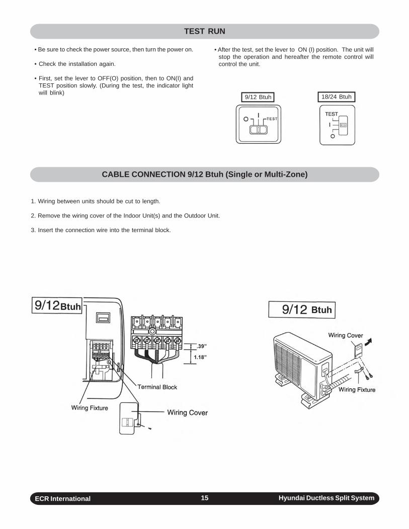
• After the test, set the lever to ON (I) position. The unit willstop the operation and hereafter the remote control willcontrol the unit.
TEST RUN
CABLE CONNECTION 9/12 Btuh (Single or Multi-Zone)
• Be sure to check the power source, then turn the power on.
• Check the installation again.
• First, set the lever to OFF(O) position, then to ON(I) andTEST position slowly. (During the test, the indicator lightwill blink)
18/24 Btuh9/12 Btuh
1. Wiring between units should be cut to length.
2. Remove the wiring cover of the Indoor Unit(s) and the Outdoor Unit.
3. Insert the connection wire into the terminal block.
ECR International Hyundai Ductless Split System16
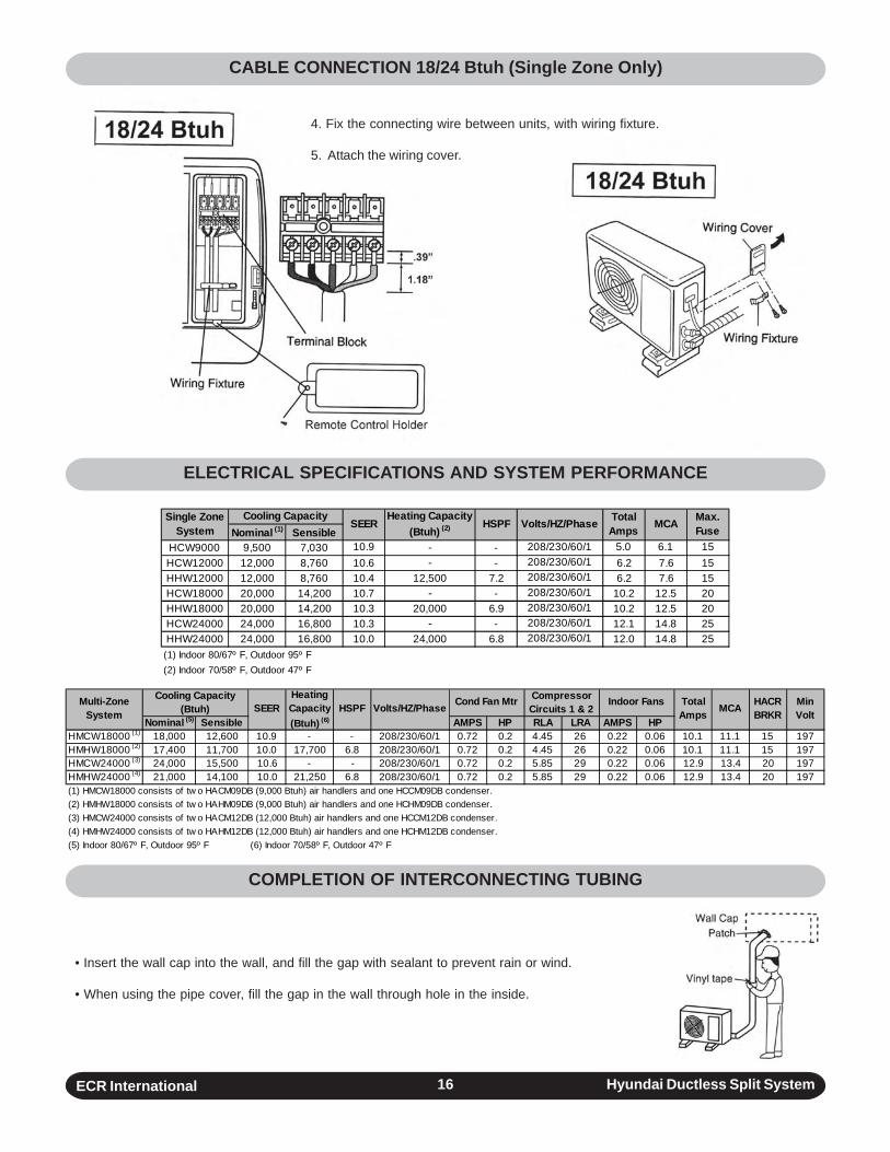
CABLE CONNECTION 18/24 Btuh (Single Zone Only)
ELECTRICAL SPECIFICATIONS AND SYSTEM PERFORMANCE
4. Fix the connecting wire between units, with wiring fixture.
5. Attach the wiring cover.
Nominal (1) SensibleHCW9000 9,500 7,030 10.9 - - 208/230/60/1 5.0 6.1 15HCW12000 12,000 8,760 10.6 - - 208/230/60/1 6.2 7.6 15HHW12000 12,000 8,760 10.4 12,500 7.2 208/230/60/1 6.2 7.6 15HCW18000 20,000 14,200 10.7 - - 208/230/60/1 10.2 12.5 20HHW18000 20,000 14,200 10.3 20,000 6.9 208/230/60/1 10.2 12.5 20HCW24000 24,000 16,800 10.3 - - 208/230/60/1 12.1 14.8 25HHW24000 24,000 16,800 10.0 24,000 6.8 208/230/60/1 12.0 14.8 25
(1) Indoor 80/67º F, Outdoor 95º F(2) Indoor 70/58º F, Outdoor 47º F
Max. FuseHSPF Volts/HZ/Phase Total
Amps MCASingle Zone System
Cooling Capacity SEER
Heating Capacity (Btuh) (2)
COMPLETION OF INTERCONNECTING TUBING
• Insert the wall cap into the wall, and fill the gap with sealant to prevent rain or wind.
• When using the pipe cover, fill the gap in the wall through hole in the inside.
Nominal (5) Sensible AMPS HP RLA LRA AMPS HPHMCW18000 (1) 18,000 12,600 10.9 - - 208/230/60/1 0.72 0.2 4.45 26 0.22 0.06 10.1 11.1 15 197HMHW18000 (2) 17,400 11,700 10.0 17,700 6.8 208/230/60/1 0.72 0.2 4.45 26 0.22 0.06 10.1 11.1 15 197HMCW24000 (3) 24,000 15,500 10.6 - - 208/230/60/1 0.72 0.2 5.85 29 0.22 0.06 12.9 13.4 20 197HMHW24000 (4) 21,000 14,100 10.0 21,250 6.8 208/230/60/1 0.72 0.2 5.85 29 0.22 0.06 12.9 13.4 20 197(1) HMCW18000 consists of tw o HACM09DB (9,000 Btuh) air handlers and one HCCM09DB condenser.(2) HMHW18000 consists of tw o HAHM09DB (9,000 Btuh) air handlers and one HCHM09DB condenser.(3) HMCW24000 consists of tw o HACM12DB (12,000 Btuh) air handlers and one HCCM12DB condenser.(4) HMHW24000 consists of tw o HAHM12DB (12,000 Btuh) air handlers and one HCHM12DB condenser.(5) Indoor 80/67º F, Outdoor 95º F (6) Indoor 70/58º F, Outdoor 47º F
Min Volt
Indoor Fans Total Amps MCA HACR
BRKRHSPF Volts/HZ/Phase Cond Fan Mtr Compressor Circuits 1 & 2
Multi-Zone System
Cooling Capacity (Btuh) SEER
Heating Capacity (Btuh) (6)
ECR International Hyundai Ductless Split System17
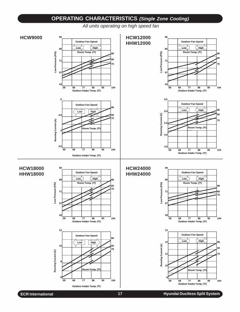
OPERATING CHARACTERISTICS (Single Zone Cooling)All units operating on high speed fan
99
85
86
71 80
75
57
4359 68 77 86 95 104
Outdoor Intake Temp. (°F)
5
86
4.5 8075
4Room Temp. (°F)
3.559 68 77 86 95 104
Outdoor Intake Temp. (°F)
Run
ning
Cur
rent
(A)
Outdoor Fan Speed
Low
Pre
ssur
e (P
SI)
Outdoor Fan Speed
Room Temp. (°F)
Low High
Low High
HCW9000 HCW12000HHW12000
99
85
86
7180
75
57
4359 68 77 86 95 104
Outdoor Intake Temp. (°F)
6.5
6.0 86
80
5.575
Room Temp. (°F)
5.0
4.559 68 77 86 95 104
Outdoor Intake Temp. (°F)
Run
ning
Cur
rent
(A)
Outdoor Fan Speed
Low
Pre
ssur
e (P
SI)
Outdoor Fan Speed
Room Temp. (°F)
Low High
Low High
99
85 86
80
7175
57
4359 68 77 86 95 104
Outdoor Intake Temp. (°F)
12
86
10 8075
8
Room Temp. (°F)
659 68 77 86 95 104
Outdoor Intake Temp. (°F)
Run
ning
Cur
rent
(A)
Outdoor Fan Speed
Low
Pre
ssur
e (P
SI)
Outdoor Fan Speed
Room Temp. (°F)
Low High
Low High
99
85
86
71 8075
57
4359 68 77 86 95 104
Outdoor Intake Temp. (°F)
13
12 86
80
11 75
10
Room Temp. (°F)
959 68 77 86 95 104
Outdoor Intake Temp. (°F)
Run
ning
Cur
rent
(A)
Outdoor Fan Speed
Low
Pre
ssur
e (P
SI)
Outdoor Fan Speed
Room Temp. (°F)
Low High
Low High
HCW18000HHW18000
HCW24000HHW24000
ECR International Hyundai Ductless Split System18
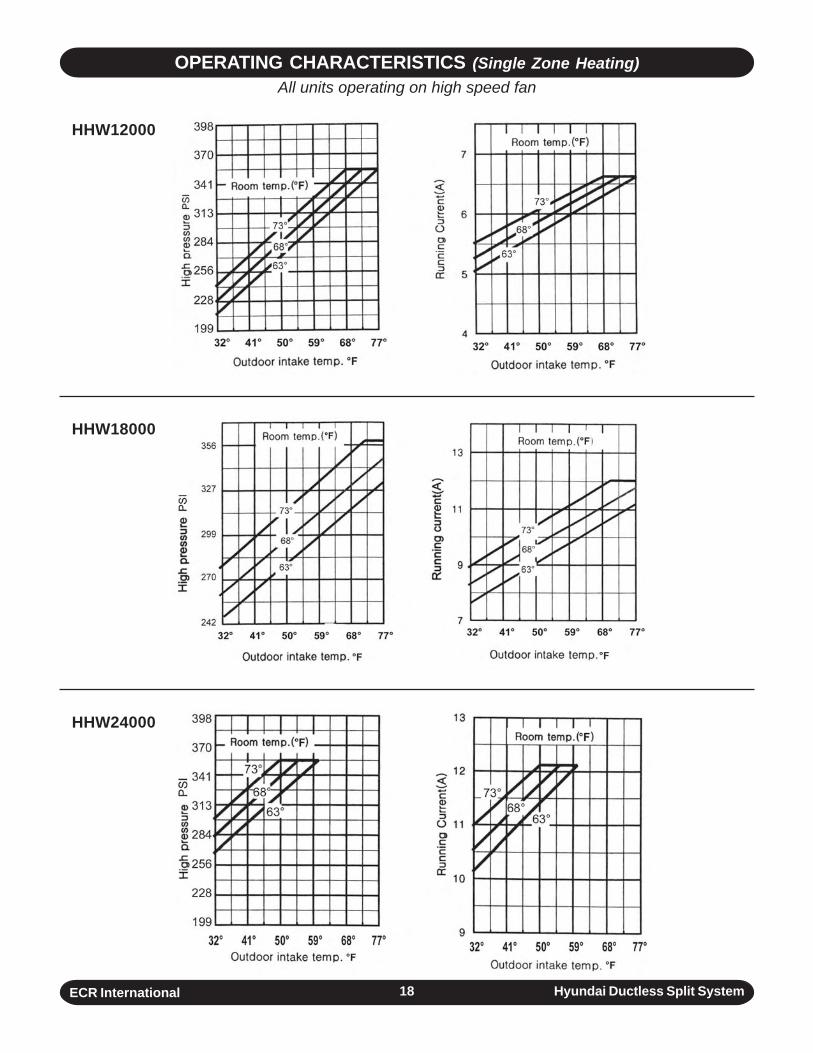
OPERATING CHARACTERISTICS (Single Zone Heating)All units operating on high speed fan
HHW12000
HHW18000
HHW24000
ECR International Hyundai Ductless Split System19
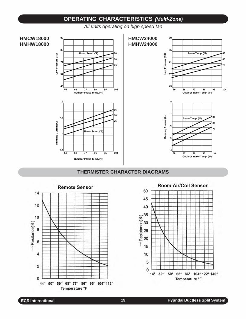
OPERATING CHARACTERISTICS (Multi-Zone)All units operating on high speed fan
HMCW18000HMHW18000
HMCW24000HMHW24000
99
8586
7180
75
57
4359 68 77 86 95 104
Outdoor Intake Temp. (°F)
5
86
4.580
75
4Room Temp. (°F)
3.559 68 77 86 95 104
Outdoor Intake Temp. (°F)
Run
ning
Cur
rent
(A)
Low
Pre
ssur
e (P
SI) Room Temp. (°F)
99
8586
7180
75
57
4359 68 77 86 95 104
Outdoor Intake Temp. (°F)
8
7
Room Temp. (°F) 86
680
75
5
468 77 86 95 104
Outdoor Intake Temp. (°F)
Run
ning
Cur
rent
(A)
Low
Pre
ssur
e (P
SI) Room Temp. (°F)
THERMISTER CHARACTER DIAGRAMS