Embed Size (px)
Citation preview

W W W . F E A I N F O R M A T I O N . C O M
C O V E R S T O R Y
J e t P r o p u l s i o n L a b o r a t o r y
P a c e Q u i c k e n s f o r N A S A S p a c e c r a f t
O r b i t i n g M a r s
P R O D U C T S P O T L I G H T
L S - D Y N A ® D e v e l o p m e n t
C O N F E R E N C E S P O T L I G H T
MSC.Software
V i r t u a l P r o d u c t D e v e l o p m e n t C o n f e r e n c e
J u l y 1 7 – 1 9 , 2 0 0 6
H u n t i n g t o n B e a c h , C A
J U N E2 0 0 6
F E A I N F O R M A T I O N R E S O U R C E M A G A Z I N E
I N F O R M AT I O N

FeaInformation.com 1
FEA Information Worldwide Participants
01 Index 02 FEA Announcements 03 LS-DYNA Development –excerpt from presentation 11 Pace Quickens for NASA Spacecraft Orbiting Mars 13 Yahoo Group Yammerings 17 MSC.Software VPD Conference Keynote Speakers 19 SGI – Illinois Researchers Bring a Dream to Life with SGI® Altix® 23 Top Crunch News 25 Courses – LSTC Training Classes 2006 27 EVENTS 28 LS-DYNA Resource Page 34 Hardware & Computing and Communication Products 35 Software Distributors 37 Consulting and Engineering Services 38 Educational & Contributing Participants 39 China Participants 41 Informational Websites 42 New Features in LS-OPT® Version3
Editor: Trent Eggleston
Managing Editor: Marsha Victory
Technical Editor: Art Shapiro
Graphic Designer: Wayne L. Mindle
Technical Writers: Dr. David Benson Uli Franz Dr. Ala Tabiei Suri Bala
Technical Consultants: Steve Pilz Reza Sadeghi
Contents

FeaInformation.com 2
FEA Information Announcements Revsied Resource Page
TABLE 2: MPP Interconnect and MPI PathScale Infinipath has been updated to Qlogic Infinipath. For website information the URL is www.qlogic.com
LSTC Announcement - Released 06/16/2006
LS-DYNA 971/7600 LS-OPT 3.1
LS-DYNA Released Versions Authorized for Benchmark Results
TopCrunch
SMP/MPP
06/15/06 Version ls970.6763.169
Sincerely, Trent Eggleston & Marsha Victory The content of this publication is deemed to be accurate and complete. However, FEA Information Inc. doesn’t guarantee or warranty accuracy or completeness of the material contained herein. All trade-marks are the property of their respective owners. This publication is published for FEA Information Inc., copyright 2003. All rights reserved. Not to be reproduced in hardcopy or electronic copy. Note: All reprinted full articles, excerpts, notations, and other matter are reprinted with permission and full copyright remains with the original author or company designated in the copyright notice

FeaInformation.com 3
LS-DYNA® Development, © Copyright 2006 LSTC 9th International LS-DYNA® Users Conference - INTRODUCTION LS-DYNA Development
• We recognize that no single method is superior in all applications • New developments and methodologies take time before gaining general accep-
tance and robustness • Requests for developments from users are given the highest development pri-
ority • Accuracy, speed, and scalability are the critical considerations for large scale
simulations • New releases must accept and run all input files from all previous releases
without translation DEVELOPMENT GOALS
• Combine multi-physics capabilities in a scalable code for solving highly nonlin-ear transient problems to enable the solution of coupled multi-physics and multi-stage problems in one run
•Full 2D & 3D capabilities •Explicit Solver •Implicit Solver •Heat Transfer •ALE, EFG, SPH, particle methods •Navier-Stokes Fluids (version 980) •Radiation transport (version 980) •Electromagnetics (version 980) •Interfaces for users, i.e., elements, materials, loads, etc. •Interfaces with other software, Madymo, USA, etc.
DEVELOPMENT GOALS - Implicit
• Springback for sheet metal stamping • Static initialization of crash models • Dynamic springback simulation after crash simulation
o Reliable measurements between numerical and physical results can be more easily obtained
• An embedded linear capability to automatically solve for normal modes, at-tachment modes, and constraint modes
o Include infinitesimal motions superimposed on rigid bodies for NVH and durability modeling
• Eigenvalue analysis to check the rigid body modes in the crash models o Identify inadvertent constraints

FeaInformation.com 4
DEVELOPMENT OF ONE CODE HAS ADVANTAGES
• Huge cost savings relative to developing an array of software applications. o Explicit elements only need added stiffness matrix o Features needed for implicit applications are available for explicit
Double precision 2nd order stress updates
• Implicit MPP utilizes all prior efforts for explicit solver • Pre and post-processing software development supports one interface and
common databases •• QA is performed on one code.
LSTC’s Vision
• In automotive, one model for crash, durability, NVH shared and maintained across analysis groups
• One scalable multi-physics code, LS-DYNA, to enable the complete modeling of crash including airbags, occupants, and fuel tank.
• Manufacturing simulation results from LS-DYNA used in crash, durability, and NVH modeling
• Explicit durability and NVH modeling go mainstream in MD Nastran • No optional added cost LSTC developed features in LS-DYNA • LS-DYNA specific pre-processing, post-processing, LS-PrePost, and optimiza-
tion, LS-OPT, with no added charges. • Unrestricted open databases • Focus on large distributed memory low-cost clusters running large simulations • As processor costs decrease and cluster sizes increase, LS-DYNA software
prices per processor will proportionally decrease to keep simulation costs af-fordable
• Optimization technology will automate engineering design calculations. LS-OPT is considered a critical enabling technology
Current State of Explicit
• Currently, typical large simulation models typically contain 1,000000 to 4,000,000 elements.
• FEA dummies are preferred over rigid body dummies in crash simulations • 12-32 processors are used in runs that complete within 12-24 hours • Calculations give digit-to-digit repeatability for a fixed domain decomposition. • MPP version is recommended if more than 4 processors are used per run • Model sizes continue to grow faster than Processor speed

FeaInformation.com 5
Near Future For Explicit
• Model sizes of 10,000,000 elements • 128-512 processors in overnight runs • Human dummy models, such as THUMS, will increase model sizes even further • Honeycomb barriers will be modeled by shell elements • Number of processors will increase 5-10 times • Optimization software use in crash analysis will become widespread
Final Goal For Explicit Simulations
• Simulation results accepted in place of prototype testing o What is required?
Strict modeling guidelines for analysts, and a single comprehen-sive model for crash, NVH, Durability, etc.
Continued software improvements • Constitutive models • Contact • FSI with SPH, ALE, Particle methods • Sensors and control systems • Complete compatibility with NASTRAN
Manufacturing simulations (in LS-DYNA, Moldflow, etc.) providing the initial conditions for crash simulations
Parallel Computing
• In less than one decade from 1998-2006 the use of explicit codes has under-gone a radical transformation
o From 100% serial and SMP licensed CPU’s for crash to 90% MPP with the remaining 10% of CPU’s typically running smaller models on 1-8 processors
o Today serial and SMP explicit codes are becoming obsolete and will eventually be phased out
• What about implicit?
o More difficult to create an MPP version o Requires more expensive hardware so there is less customer pressure to
create MPP versions o However, it is safe to predict that serial and SMP implicit solvers used in
large scale nonlinear simulations will also become obsolete within the next 5 years

FeaInformation.com 6
Scalability On Large Clusters
• IBM BlueGene/L computer is based on low cost PowerPC processors with mod-est clock speed, low power consumption, high speed network
• 2**16 (65000+) parallel processors • Scalability of LS-DYNA on 1,048,576 element customer model run to comple-
tion: o 128 -Elapsed time 5 hours 27min. 437564 cycles o 256 -Elapsed time 2 hours 44min. 437564 cycles o 512 -Elapsed time 1 hour 27min. 437564 cycles o 1024 -Elapsed time 50min. 437564 cycles o 2048 -Elapsed time 32min. 437564 cycles
• Cray XD1 with RapidArray interconnects AMD Dual Core Opteron 2.2 GHz • 3 Car crash simulation run to completion (750K nodes)
Dual Core (Nodes x CPUs/node x Cores/cpu)
CPU Time (sec)
Single Core (Nodes x CPUs/node x Cores/cpu)
CPU Time (sec)
64 x 2 x 2 = 256 32 x 2 x 2 = 128 24 x 2 x 2 = 96 16 x 2 x 2 = 64 12 x 2 x 2=48 8 x 2 x 2 = 32 4 x 2 x 2 = 16 2 x 2 x 2 = 8 1 x 2 x 2 = 4
1696 2416 2981 3846 5226 7591 14078 26230 49460
32 x 2 x 1 = 64 4 x 2 x 1 = 8 2 x 2 x 1 = 4
4619 24681 47611
Release Of Version 971_R2
• Version 971 was intended to be an update to version 970 to include parallel implicit
• Implementation of implicit parallel has taken years longer than planned • Version 971_R1 was released during the 4th quarter of 2005
o Multiple customers requested additional capabilities before switching from version 970
• Version 971_R2 now includes nearly all additional requested capabilities • Manual will be published by August 2006 and will include new features in the
R3 release. Version 971_R2 Developments *Database_extent_binary
• New flag to output nodal mass scaling information into the D3PLOT database o EQ.1: Output incremental nodal mass o EQ.2: Output percentage increase in nodal mass
FeaInformation.com 7
• In the past only the change in mass at the element level was available • New output options for metal forming applications • For each contact interface a new flag is available to output:
o peak pressure o surface energy density
• Allows segregating the energies generated on the upper and lower shell sur-faces
• Data is remapped after each H-adaptive remesh. • For metalforming applications with thermal effects, there is a new option to
output of thermal data to d3plot: o EQ.0: (default) output temperature o EQ.1: output temperature and flux o EQ.2: output temperature, flux, and shell lower and upper surface tem-
peratures for the 12-node thermal shells *Database_nodout
• The size for the nodal history file NODOUT can be huge due to the need for have a small set of nodal output at a very high frequency
• Two NODOUT files can now be created: o NODOUT at a large output time interval o NODOUTHF at a small output time interval
For accelerometer nodes • Nodes for high frequency output are flagged in *DATABASE_HISTORY_NODE input
*Database_matsum
• *CONTROL_OUTPUT flag to: o Output eroded internal and kinetic energy into the MATSUM file by part ID. o Output the kinetic energy from the added mass under part ID 0, which
includes mass defined under: *ELEMENT_MASS Nonstructural mass distributions defined in *SECTION_SHELL *ELEMENT_MASS_PART.
Labels and Numeric ID’s
• 8-character alphanumeric labels can now be used for: SECID, MID, EOSID, HGID, and TMID throughout the keyword input
Card 1 2 3 4 5 6 7 8 Variable PID SECID MID EOSID HGID GRAV ADPOPT TMID Type I I/A I/A I/A I/A I I I/A Default none none none 0 0 0 0 0

FeaInformation.com 8
*Element_mass_part
• Defines the total additional non-structural mass to be distributed by an area weighted distribution to all nodes of a given part ID.
• Applies to all part ID’s defined by shell elements. • Provides an alternative method to giving the non-structural mass per unit area
in the section definition. *Define_hex_spotweld_assembly
• Development motivated by spotweld studies at Honda USA which showed the superiority of using multiple solid elements for each weld.
• Define a list of hexahedral solid elements clusters that make up a single spot weld for computing the force and moment resultants that are written into the SWFORC output file and also used for failure predictions.
• A maximum of a 16 element cluster may be used to define single spot weld. • This table is generated automatically when beam elements are converted to
solid elements.
• Sample four, eight, and sixteen element spot weld clusters comprised of solid hexahedron elements. {Courtesy Honda, USA}
*CONTROL_SPOTWELD_BEAM
• New option to replace each spot weld beam element with a cluster of solid elements of 1, 4, or 8 solid elements.
• For 4 or 8 solid elements, a table is automatically generated to output the force and moment resultants into the SWFORC using the ID of the beam ele-ment which is replaced by the solid elements and for failure predictions
• The beam elements are automatically deleted from the calculation, and the section and material data is automatically changed to be used with solid ele-ment or solid element cluster

FeaInformation.com 9
Spot weld Failure
• The recent use of high strength steels has motivated new developments for predicting spot weld failure
o With mild steels the spot weld failure mode is tear out o With high strength steels the failure mode is either tear out or spot weld
fracture Depends on the ratio of shear versus axial loading
• Two failure models are now available: the first for beam elements, developed by Toyota; and the second for single solid elements, developed by Daimler-Chrysler
Spot weld New Development
• New constitutive model: *MAT_SPOTWELD_ DAIMLERCHRYSLER o The DAIMLERCHRYSLER failure model assumes that failure of the spot
weld depends on properties of the welded materials so this keyword al-lows shell material failure data to be input for the connection
o References connection ID which is defined via: *DEFINE_CONNECTION_PROPERTIES
o Implemented for single solid elements o Includes damage and rate effects o Much easier to use and more general than the previous option:
*DEFINE_SPOTWELD_FAILURE_RESULTANTS
• *DEFINE_CONNECTION_PROPERTIES o References material ID’s used in part definitions and defines a failure
criteria for the material ID’s. o One or more connection ID’s can be defined o A 3-parameter failure criteria is used
( ) ( ) ( )1
n bm m m
n bF F Fn b
fτ
σ σ τσ ε σ ε τ ε⎛ ⎞ ⎛ ⎞ ⎛ ⎞
= + + −⎜ ⎟ ⎜ ⎟ ⎜ ⎟⎜ ⎟ ⎜ ⎟ ⎜ ⎟⎝ ⎠ ⎝ ⎠ ⎝ ⎠
2 2 2 2
2
rs rt rs rtrr rrn b
M M N NN MA Z Z A
σ σ τ+ +
= = = +

FeaInformation.com 10
Sensors For Automotive Safety
• There are over 110 sensors in the average vehicle today, e.g., o pressure sensor for brake, tire o Force and torque sensor for suspension o Acceleration, velocity and displacement sensor for suspension, vehicle
and occupant o Occupant classification sensor for restraint system o Strain gauge for steel and seat
*SENSOR
• *SENSOR_DEFINE defines a physical sensor. The output signal is the numerical value of a physical sensor.
• *SENSOR_SWITCH compares the sensor signal with a given criterion. The out-put signal is the logical result, true or false.
• *SENSOR_CONTROL controls a function, airbag, contact,…, based on the logi-cal result of a set of SENSOR_SWITCH. Multiple status switch is possible.
*Contact_force_tranducer
• Scalability of LS-DYNA to hundred’s of processors is limited by contact o Scalability for 1-2 contact definitions covering the entire vehicle is excellent o Scalability for 300+ contact definitions diminishes significantly as the
number of processors increase 300 contact definitions are used to obtain detailed reaction force
information. • Force transducers measure contact forces within a vehicle by accumulating all
forces acting on a segment set during contact. o Problem is that these transducers cannot separate the forces in two-
sided contact • In version 971_R2 a master surface is also accepted such that the reaction
force is accumulated by the interactions of the slave and master surfaces o It is now possible to move to fewer contact interfaces and improve scalability.
FeaInformation.com 11
Jet Propulsion Laboratory – California Inst. of Technology © Copyright 2006 www.jpl.nasa.gov
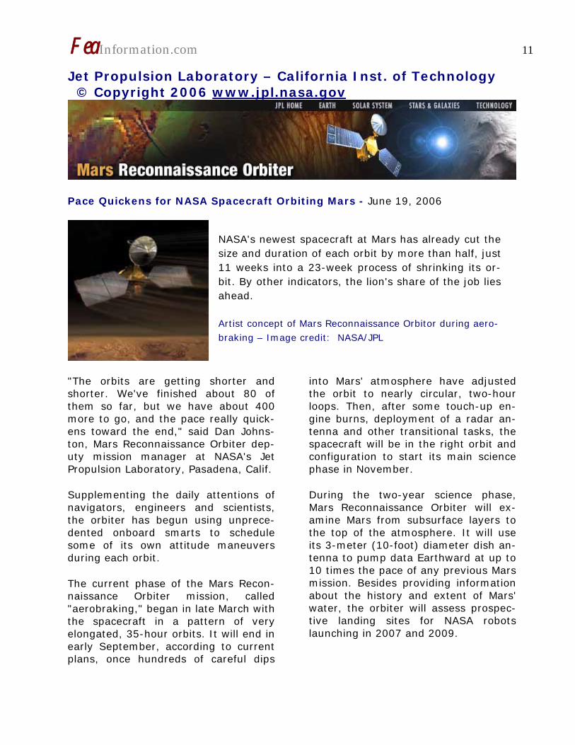
Pace Quickens for NASA Spacecraft Orbiting Mars - June 19, 2006
"The orbits are getting shorter and shorter. We've finished about 80 of them so far, but we have about 400 more to go, and the pace really quick-ens toward the end," said Dan Johns-ton, Mars Reconnaissance Orbiter dep-uty mission manager at NASA's Jet Propulsion Laboratory, Pasadena, Calif.
Supplementing the daily attentions of navigators, engineers and scientists, the orbiter has begun using unprece-dented onboard smarts to schedule some of its own attitude maneuvers during each orbit.
The current phase of the Mars Recon-naissance Orbiter mission, called "aerobraking," began in late March with the spacecraft in a pattern of very elongated, 35-hour orbits. It will end in early September, according to current plans, once hundreds of careful dips
into Mars' atmosphere have adjusted the orbit to nearly circular, two-hour loops. Then, after some touch-up en-gine burns, deployment of a radar an-tenna and other transitional tasks, the spacecraft will be in the right orbit and configuration to start its main science phase in November.
During the two-year science phase, Mars Reconnaissance Orbiter will ex-amine Mars from subsurface layers to the top of the atmosphere. It will use its 3-meter (10-foot) diameter dish an-tenna to pump data Earthward at up to 10 times the pace of any previous Mars mission. Besides providing information about the history and extent of Mars' water, the orbiter will assess prospec-tive landing sites for NASA robots launching in 2007 and 2009.
NASA's newest spacecraft at Mars has already cut the size and duration of each orbit by more than half, just 11 weeks into a 23-week process of shrinking its or-bit. By other indicators, the lion's share of the job lies ahead.
Artist concept of Mars Reconnaissance Orbitor during aero-braking – Image credit: NASA/JPL

FeaInformation.com 12
When the spacecraft first entered orbit around Mars, its farthest point from the planet was about 45,000 kilometers (28,000 miles). After 11 weeks of aerobraking operations, this distance has been reduced to about 20,000 kilometers (12,000 miles). On each or-bit since early April, the nearest-to-Mars portion of the orbit has passed through the upper atmosphere, usually at about 105 kilometers (65 miles) above the surface of the planet. The drag created by interaction of the at-mosphere with spacecraft surfaces slows the craft.
"Our biggest challenge is the variability of the atmosphere," Johnston said. "It's not uncommon to get a 35 percent change in how much drag the space-craft experiences from one pass to the next. We need to monitor each pass carefully and be prepared to change the altitude to a safe one for the next pass, if necessary."
While the orbiter is above the atmos-phere, it can orient its antenna toward Earth and its solar panels toward the sun. Before it enters the atmosphere for each pass, it pivots so that the back surfaces of the solar panels and an-tenna face the direction of travel. An innovative capability of Mars Recon-naissance Orbiter's onboard software enables it to calculate the time when it needs to reorient itself for the next pass. This feature, called "periapsis timing estimator," was activated in May.
JPL's Jim Graf, project manager for Mars Reconnaissance Orbiter, said, "In the past, the times for turning to aero-braking attitude had to be calculated on the ground and sent to the space-craft for each pass. Now, the space-
craft can do that itself. This will be es-pecially helpful when the spacecraft gets to the point when it is doing sev-eral drag passes per day."
Mars Reconnaissance Orbiter is the third NASA Mars mission -- after Mars Global Surveyor in 1997 and Mars Od-yssey in 2001 -- to use aerobraking to get into a desired, near-circular orbit. The strategy allows launching the spacecraft with much less fuel than would be required if using just rocket engines to decelerate into the desired orbit. Each drag pass this month is slowing Mars Reconnaissance Orbiter by an average of about 2 meters per second (4.5 miles per hour), which would otherwise require consuming about a kilogram (2.2 pounds) of fuel.
Transition activities during the two months between the end of aerobrak-ing and the beginning of the main sci-ence phase will include unfolding two 5-meter (16-foot) lengths of antenna for a ground-penetrating radar instru-ment, removing the lens cap from a mineral-identifying spectrometer in-strument and characterizing all instru-ments' performance in different modes of use. From early October to early No-vember, Mars will be nearly behind the sun as viewed from Earth. Communica-tion with all spacecraft at Mars will be unreliable during portions of that pe-riod, so commanding will be minimized.
Additional information about Mars Recon-naissance Orbiter is available online at http://www.nasa.gov/mro . The mission is managed by JPL, a division of the California Institute of Technology, Pasadena, for the NASA Science Mission Directorate, Wash-ington. Lockheed Martin Space Systems, Denver, is the prime contractor for the pro-ject and built the spacecraft.

FeaInformation.com 13
Yahoo Group Yammerings
Jim Kennedy KBS2 Inc. [email protected]
Len Schwer Schwer Engineering & Consulting Services [email protected]
Len Schwer will be conducting an LS-DYNA ‘Discussion Group Forum’ at the 77th Shock & Vibration Symposium, October 29 - November 3, 2006 at the Hyatt Regency Monterey in Monterey, CA. Visit www.saviac.org for more details.
This installment of “Yahoo Yammerings” features four questions, with responses, and two posting of general interest, from the past month of postings to the LS-DYNA Ya-hoo Group:
1. Geometric Nonlinearity? 2. Using MAT_RIGID versus RIGIDWALL_GEOMETRIC? 3. How to Model Local Material Softening Response Artificially 4. Bolt Failure Criteria? 5. Contact Algorithm - Calculation of Minimum Time Step. 6. Intel Core Duo CPU Comparison.
Question: Geometric Nonlinearity? Does LS DYNA takes geometric nonlin-earities into account by default? If not, how to include it in the analysis? Which element types can handle geometrical nonlinearity? Does it have something to do with material models? I am trying to model low velocity im-pact behavior on sandwich panels. The dimensions of sandwich plate is 300mm x 300mm x 25.7 mm, and I am getting maximum z-displacement of 5.1 mm. which means I have large displacements for my model and should consider geometrical nonlinear-ity. Response by Jim Kennedy It is my understanding that most of the widely used elements incorporated in the LS-DYNA use a large deformation
formulation. Please see the LS-DYNA Theory Manual. LS-DYNA outputs the Cauchy (true) stress and true strain. The nonlinear material behavior will depend on your constitutive model choice from the large material law li-brary. In addition, some linear material laws are available. Question : Using MAT_RIGID ver-sus RIGIDWALL_GEOMETRIC? I am doing a impact analysis of rigid sphere impacting a plate. For the rigid sphere I have taken MAT_RIGID (MAT_020) material model and I have specified the mass density according to its weight and volume; I do not know the material of the sphere. Is it neces-sary to specify Young’s modulus and Poisson’s ratio for the rigid sphere?

FeaInformation.com 14
What is the difference between MAT_RIGID and RIGIDWALL_GEOMETRIC_SPHERE? Will both provide the same results? Response by Jim Kennedy Reasonable values of Young's modulus and Poisson's should be used for the rigid material to minimize problems with the contact (please see pages 20.82 and 20.84 of the LS-DYNA Ver-sion 970 User's Manual). MAT_RIGID is used to provide the ma-terial model used for a meshed arbi-trary body. RIGIDWALL_GEOMETRIC_SPHERE de-fines a rigid wall via an analytical de-scription. If good modeling practices are used, they should give similar results. Question: How to Model Local Ma-terial Softening Response Artifi-cially I am working with an SPH model, i.e. cylindrical rotating rigid part plunging into SPH plate. In reality there is local-ized thermal softening of the material. However, from prior knowledge, I know SPH does not support a thermal solu-tion. (I do not know/think if the situa-tion has since changed). Anyway, an alternative would be to obtain a soften-ing response by inducing it artificially. My original model uses a Johnson Cook constitutive model. Currently, I am us-ing MAT_PLASTIC_KINEMATIC (MAT 3) for simplicity reasons. Some of the ideas, I have are:
1. Decreasing the ETAN value in Mat_3 to a smaller value (3 or +more orders less than E) or a negative value. (I have tried this, and see a decrease to the order of .about 10^8. Any comments on my approach? Can someone answer which direction should my approach go, and how to visually (or by observing stress/strain values) can a softening response be observed in LS-PrePostt? Response by Jim Kennedy I would suggest using the Johnson-Cook model (MAT_015) as a structural only problem. I also suggest reading the following paper to understand how the thermal softening is addressed in the Johnson-Cook model: Johnson, G.R. and W.H. Cook, "A Con-stitutive Model and Data for Metals Subjected to Large Strains, High Strain Rates, and High Temperatures," 7th International Symposium on Ballistics, pp. 541-547, The Hague, Netherlands, April 1983. In the structural only approach, the adiabatic heating is calculated if you enter a value for specific heat CP on the *MAT_JOHNSON_COOK keyword. Temperature change is calculated by dividing the plastic work by (rho)*(cp). This temperature change is used in cal-culating T* (please see page 20.64 of the LS-DYNA Version 970 User's Man-ual). The temperature is written to d3plot as HV#1 (NEIPH=0) or HV#5 (under the Fcomp/MISC menu of LS-PrePost, after setting NEIPH=6 on the LS-DYNA input *DATABASE_EXTENT_BINARY).

FeaInformation.com 15
Question Bolt Failure Criteria? How do I use the force failure criteria with beam elements. I have modeled a bolt with a beam element and I want to have it break during a quasi-static simulation if the beam experiences an axial force greater than a set axial force target value and resultant shear force greater than a set shear force target value. The ultimate would be to have a bolt force failure criteria set using the com-bination of tensile -shear force experi-mental curve. I am not sure if LS-DYNA has this feature? Response by Jim Kennedy Two things you might consider: 1. Write your own User Supplied mate-rial Model (UMAT). 2. This type of failure is specified in *CONSTRAINED_SPOTWELD and *CONTACT_TIEBREAK_Options, you might consider modifying your model to make use of these features, e.g., join beam nodes by welds. Follow-up by Conrad Izatt In addition to the two suggestions from James, you could try using a ‘discrete’ beam (beam type 6) instead and com-bine it with using *MAT_NONLINEAR_PLASTIC_DISCRETE_BEAM. This will allow you to define the yield, plastic and failure behavior for all 6 degrees of freedom with basic interactions.
Contact Algorithm - Calculation of Minimum Time Step Posting by Len Schwer Lee Bindeman of LSTC recently pro-vided some insight on the calculation of the minimum time step size for the contact algorithms in LS-DYNA. I thought this me be of interest to the Group: "For each contact interface in the model, we loop over the slave and master nodes and calculate the contact frequency of each by considering its contact stiffness (by soft=0 method) and its mass. From the Courant condi-tion, we calculate a stable time step as dt=2/w where w is the frequency. We store the smallest dt of all the nodes and report this as the surface time step. The current minimum is the smallest of all the contact interfaces that have been checked." Lee adds that for the SOFT=2 contact option, no minimum time step is com-puted. LS-DYNA Yahoo Groups There are over 1790 subscribers from all over the world, and this list seems to grow by a hundred new subscribers ever few months; no small testament to the rapidly growing popularity of LS-DYNA. The group currently aver-ages about 250 message per month, i.e. about 10 message per day. You can subscribe to the group by sending an email request to [email protected] or by vis-iting the Yahoo Groups web site http://groups.yahoo.com

FeaInformation.com 16
Generally, the quickest/best responses are to those questions posed with the most specifics. General questions such as “How do I use XXX feature?” either go unanswered, or are answered by Jim Kennedy with links to appropriate references in the growing LS-DYNA re-lated literature, e.g. see the archive of LS-DYNA Conference proceedings at www.dynalook.com .

FeaInformation.com 17
Virtual Product Development Conference July 17 – 19, 2006 – Huntington Beach, CA
The following are excerpts – full information can be found at: http://vpd.mscsoftware.com/americas/ Among The 2006 keynote speakers are:
William Weyand - Chairman of the Board and Chief Execu-tive Officer MSC.Software Mr. Weyand assumed the role of chairman and CEO of MSC Soft-ware in February 2005 Mr. Weyand was Chairman and CEO of Structural Dynamics Re-search Corporation (SDRC) from 1997 to 2001. During that time,he redefined SDRC's strategic direction to capitalize on newgrowth opportunities, establishing the company as a market leaderin Product Lifecycle Management (PLM) solutions. Under his direc-tion, SDRC acquired seven companies. In 2001, he successfully facilitated the sale of SDRC to Electronic Data Systems (NYSE:EDS) for $1 billion
Dave Fennell - Vice President of Information Technology - Boeing Commercial Airplanes
Dave Fennell is vice president of Information Technology for TheBoeing Company. He is responsible for the design and support ofcompany-wide engineering, manufacturing and quality assurancesystems, collectively known as Product Life Cycle Management(PLM) Systems. In addition, Mr. Fennell is responsible to the Boe-ing Commercial Airplane (BCA) Business Unit…

FeaInformation.com 18
Thomas C. Tecco - Global Director, Computer-Aided Engi-neering, Electrical and Test Systems -General Motors Cor-poration Mr. Tecco is the Director of Global CAE/Test Systems and Electrical for the Information Systems and Services (IS&S) organization at General Motors. He also has responsibility for Systems Engineering and the Designing Engineer initiative.
Reza Sadeghi, Ph.D. - VP, Product Development - MSC.Software Dr. Reza Sadeghi is currently Vice President of Product Develop-ment (Enterprise Computing) at MSC.Software with responsibilityfor strategy and development of MSC's MultiDscipline Products,(Nastran, Marc, Adams, Dytran and Patran). Prior to MSC he wasresponsible for the simulation methods group at Goodrich aero-space, where he led the development of a number of math basedtools for design and manufacturing of commercial and military jetengine nacelle structures. Over the past 10 years, he has beenasked to serve on a number of science and technology review boards, among them DOE and DOD.
Dick Rutan, Commander of the World's First Non-Stop, Unrefueled Flight As a Tactical Air Command fighter pilot during most of his two decades in the Air Force, Dick Rutan few 325 combat missions in Vietnam, 105 of them as a member of a high-risk classified op-eration commonly known as the MISTY's." While on his last strike reconnaissance mission over North Vietnam in September of 1968, he was hit by enemy ground fire, and forced to eject from his burning F-100. Dick evaded enemy capture and was later rescued by the Air Force's "Jolly Green Giant" helicopter team. Before retiring from the Air Force in 1978, Lt. Col. Rutan had been awarded the Silver Star, five Distinguished Flying Crosses, 16 Air Medals and the Purple Heart. '
FeaInformation.com 19
Imitation of Life – SGI www.sgi.com
http://www.sgi.com/features/2006/june/ncsa/
For the first time, researchers simulated a complete, functioning organism at the atomic level. How NCSA's SGI Altix system helped them make history.
Picture an object with a million moving parts. Now imagine building a model to simulate that object - one that reveals how each part interacts with the other, every one-millionth-of-a-billionth of a second.
No, it's not rocket science. But it just might be harder.
For nearly as long as biophysicists have relied on computers to study the dy-namics of molecules, they've hoped to replicate a functioning life form at the atomic level. Yet even the simplest of these organisms proved too complex to simulate in total. But now, thanks to the efforts of three Illinois researchers, a highly scalable molecular dynamics application, and one very powerful computer, all that is history.
At the University of Illinois at Urbana-Champaign, two graduate students and their professor have achieved what un-til now had been patently unachiev-able. They generated the world's first atomic-level simulation of a simple, but complete, functioning organism. And they did it on an SGI® Altix® system.
A research team led by Professor Klaus Schulten, head of the Theoretical and Computational Biophysics Group at Illi-nois, simulated a plant virus with as many as 1 million moving atoms. Dr. Schulten worked with grad students Peter Freddolino and Anton Arkhipov on the year-long project, which was reported in the March 2006 issue of the scientific journal Structure.
FeaInformation.com 20
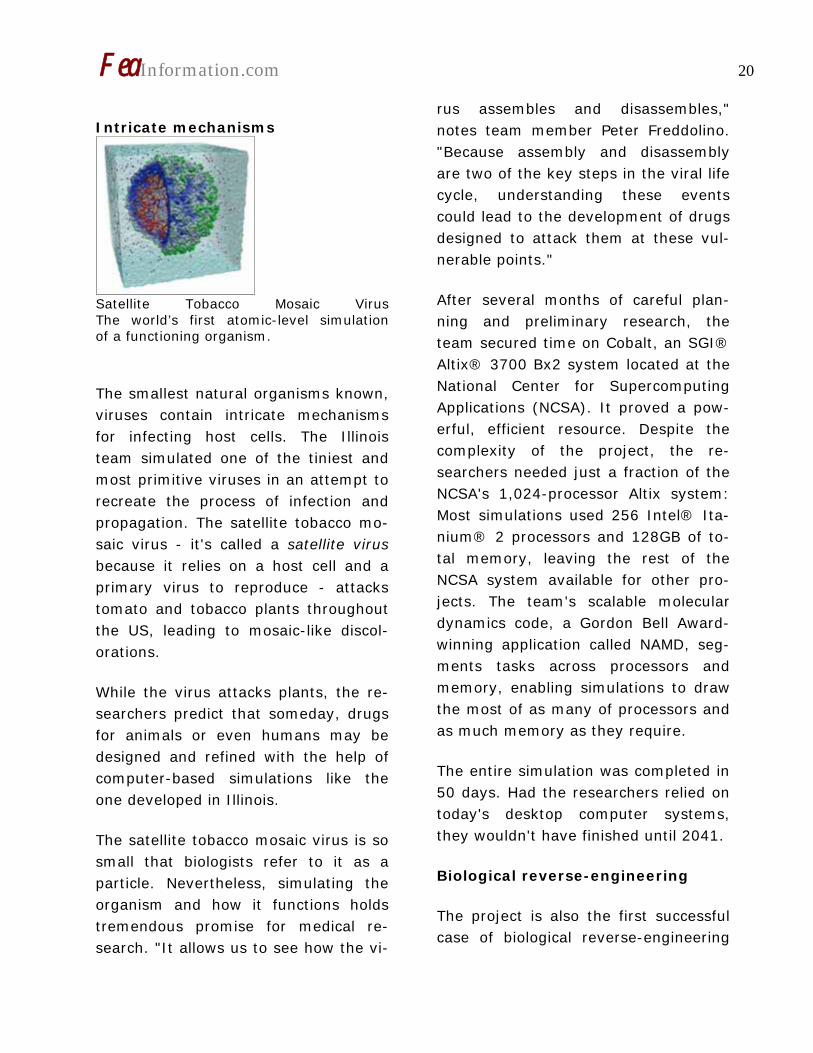
Intricate mechanisms
Satellite Tobacco Mosaic Virus The world’s first atomic-level simulation of a functioning organism.
The smallest natural organisms known, viruses contain intricate mechanisms for infecting host cells. The Illinois team simulated one of the tiniest and most primitive viruses in an attempt to recreate the process of infection and propagation. The satellite tobacco mo-saic virus - it's called a satellite virus because it relies on a host cell and a primary virus to reproduce - attacks tomato and tobacco plants throughout the US, leading to mosaic-like discol-orations.
While the virus attacks plants, the re-searchers predict that someday, drugs for animals or even humans may be designed and refined with the help of computer-based simulations like the one developed in Illinois.
The satellite tobacco mosaic virus is so small that biologists refer to it as a particle. Nevertheless, simulating the organism and how it functions holds tremendous promise for medical re-search. "It allows us to see how the vi-
rus assembles and disassembles," notes team member Peter Freddolino. "Because assembly and disassembly are two of the key steps in the viral life cycle, understanding these events could lead to the development of drugs designed to attack them at these vul-nerable points."
After several months of careful plan-ning and preliminary research, the team secured time on Cobalt, an SGI® Altix® 3700 Bx2 system located at the National Center for Supercomputing Applications (NCSA). It proved a pow-erful, efficient resource. Despite the complexity of the project, the re-searchers needed just a fraction of the NCSA's 1,024-processor Altix system: Most simulations used 256 Intel® Ita-nium® 2 processors and 128GB of to-tal memory, leaving the rest of the NCSA system available for other pro-jects. The team's scalable molecular dynamics code, a Gordon Bell Award-winning application called NAMD, seg-ments tasks across processors and memory, enabling simulations to draw the most of as many of processors and as much memory as they require.
The entire simulation was completed in 50 days. Had the researchers relied on today's desktop computer systems, they wouldn't have finished until 2041.
Biological reverse-engineering
The project is also the first successful case of biological reverse-engineering

FeaInformation.com 21
of a complete virus. "This is on the highest end of what is feasible today," says Schulten. "The approach is some-thing that we learned from engineers: Reverse engineer the subjects you're interested in and test fly them in the computer to see if they work in silico (or simulated on a computer) the way they do in vivo (in the body). Naturally, deeper understanding of the mechanis-tic properties of other, more compli-cated viruses will eventually contribute to public health and medicine."
The entire simulation covers just over 50 nanoseconds of time, or 50 bil-lionths of a second. Still, it was enough time for Schulten's team to make sev-eral conclusions about the virus. Among them: although the organism appears symmetrical, it actually pulses in and out in an asymmetrical pattern.
As it turns out, the Illinois team's simulated findings support observa-tions made by other researchers in tra-ditional "wet lab" work. Those earlier observations, however, left scientists wondering what caused the viral be-havior - something that remained a mystery until today.
They accomplished this by studying the virus not just as a whole, but as the sum of its separate components - its protein shell and nucleic acid core. "The going theory was that the protein shell pulled the entire thing together and was responsible for its assembly," explains Freddolino. "But the simula-
tion showed that the nucleic acid was even more important for keeping the virus together."
When simulated as a whole, the virus appeared stable and symmetrical. But after removing a component, the re-searchers saw how vital the nucleic acid was to the structure of the virus. "The protein shell just fell out without the nucleic acid," recalls Freddolino. "That told us a lot."
"The analysis of the results required originality," says Arkhipov, who lever-aged his physics training to analyze the diffusion of ions and other phenomena. "It's interesting to see how each part of the structure moves a little bit on its own, and how that affects its symme-try."
An invaluable resource
NCSA's large Altix system allowed the team to focus more on science than computing. "The ideal situation is to work with a powerful computing plat-form that provides output quickly and with minimal disturbance. In this way, the underlying science is the focus of the effort. NCSA provided exactly that," added Schulten, a long-time NCSA user.
"The Altix platform has excellent single node performance and a very efficient MPI implementation," said Freddolino, "and both of these factors made the

FeaInformation.com 22
system very useful in performing our work efficiently."
"It's incumbent upon centers like NCSA to make the most of the federal gov-ernment's technology investments by working closely with scientists like Pro-fessor Schulten as well as entire com-munities of scientists," said Thom Dun-ning, director, NCSA. "We have devel-
oped new ways to allocate supercom-puting resources, such as our large-scale SGI Altix deployment, to give sci-entists what they need in order to make incredible breakthroughs like the simulation of an entire living thing." Image courtesy of NCSA and University of Illinois at Urbana-Champaign
FeaInformation.com 23
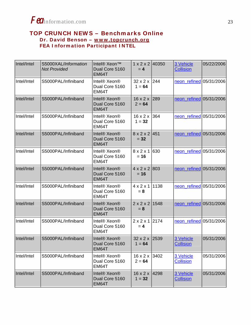
TOP CRUNCH NEWS – Benchmarks Online Dr. David Benson – www.topcrunch.org FEA Information Participant INTEL
Intel/Intel S5000XAL/Information Not Provided
Intel® Xeon™ Dual Core 5160 EM64T
1 x 2 x 2 = 4
40350 3 Vehicle Collision
05/22/2006
Intel/Intel S5000PAL/Infiniband Intel® Xeon® Dual Core 5160 EM64T
32 x 2 x 1 = 64
244 neon_refined 05/31/2006
Intel/Intel S5000PAL/Infiniband Intel® Xeon® Dual Core 5160 EM64T
16 x 2 x 2 = 64
289 neon_refined 05/31/2006
Intel/Intel S5000PAL/Infiniband Intel® Xeon® Dual Core 5160 EM64T
16 x 2 x 1 = 32
364 neon_refined 05/31/2006
Intel/Intel S5000PAL/Infiniband Intel® Xeon® Dual Core 5160 EM64T
8 x 2 x 2 = 32
451 neon_refined 05/31/2006
Intel/Intel S5000PAL/Infiniband Intel® Xeon® Dual Core 5160 EM64T
8 x 2 x 1 = 16
630 neon_refined 05/31/2006
Intel/Intel S5000PAL/Infiniband Intel® Xeon® Dual Core 5160 EM64T
4 x 2 x 2 = 16
803 neon_refined 05/31/2006
Intel/Intel S5000PAL/Infiniband Intel® Xeon® Dual Core 5160 EM64T
4 x 2 x 1 = 8
1138 neon_refined 05/31/2006
Intel/Intel S5000PAL/Infiniband Intel® Xeon® Dual Core 5160 EM64T
2 x 2 x 2 = 8
1548 neon_refined 05/31/2006
Intel/Intel S5000PAL/Infiniband Intel® Xeon® Dual Core 5160 EM64T
2 x 2 x 1 = 4
2174 neon_refined 05/31/2006
Intel/Intel S5000PAL/Infiniband Intel® Xeon® Dual Core 5160 EM64T
32 x 2 x 1 = 64
2539 3 Vehicle Collision
05/31/2006
Intel/Intel S5000PAL/Infiniband Intel® Xeon® Dual Core 5160 EM64T
16 x 2 x 2 = 64
3402 3 Vehicle Collision
05/31/2006
Intel/Intel S5000PAL/Infiniband Intel® Xeon® Dual Core 5160 EM64T
16 x 2 x 1 = 32
4298 3 Vehicle Collision
05/31/2006
FeaInformation.com 24
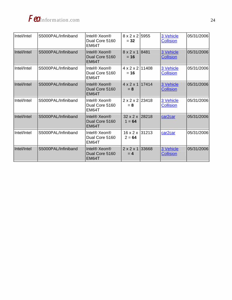
Intel/Intel S5000PAL/Infiniband Intel® Xeon®
Dual Core 5160 EM64T
8 x 2 x 2 = 32
5955 3 Vehicle Collision
05/31/2006
Intel/Intel S5000PAL/Infiniband Intel® Xeon® Dual Core 5160 EM64T
8 x 2 x 1 = 16
8481 3 Vehicle Collision
05/31/2006
Intel/Intel S5000PAL/Infiniband Intel® Xeon® Dual Core 5160 EM64T
4 x 2 x 2 = 16
11408 3 Vehicle Collision
05/31/2006
Intel/Intel S5000PAL/Infiniband Intel® Xeon® Dual Core 5160 EM64T
4 x 2 x 1 = 8
17414 3 Vehicle Collision
05/31/2006
Intel/Intel S5000PAL/Infiniband Intel® Xeon® Dual Core 5160 EM64T
2 x 2 x 2 = 8
23418 3 Vehicle Collision
05/31/2006
Intel/Intel S5000PAL/Infiniband Intel® Xeon® Dual Core 5160 EM64T
32 x 2 x 1 = 64
28218 car2car 05/31/2006
Intel/Intel S5000PAL/Infiniband Intel® Xeon® Dual Core 5160 EM64T
16 x 2 x 2 = 64
31213 car2car 05/31/2006
Intel/Intel S5000PAL/Infiniband Intel® Xeon® Dual Core 5160 EM64T
2 x 2 x 1 = 4
33668 3 Vehicle Collision
05/31/2006

FeaInformation.com 25
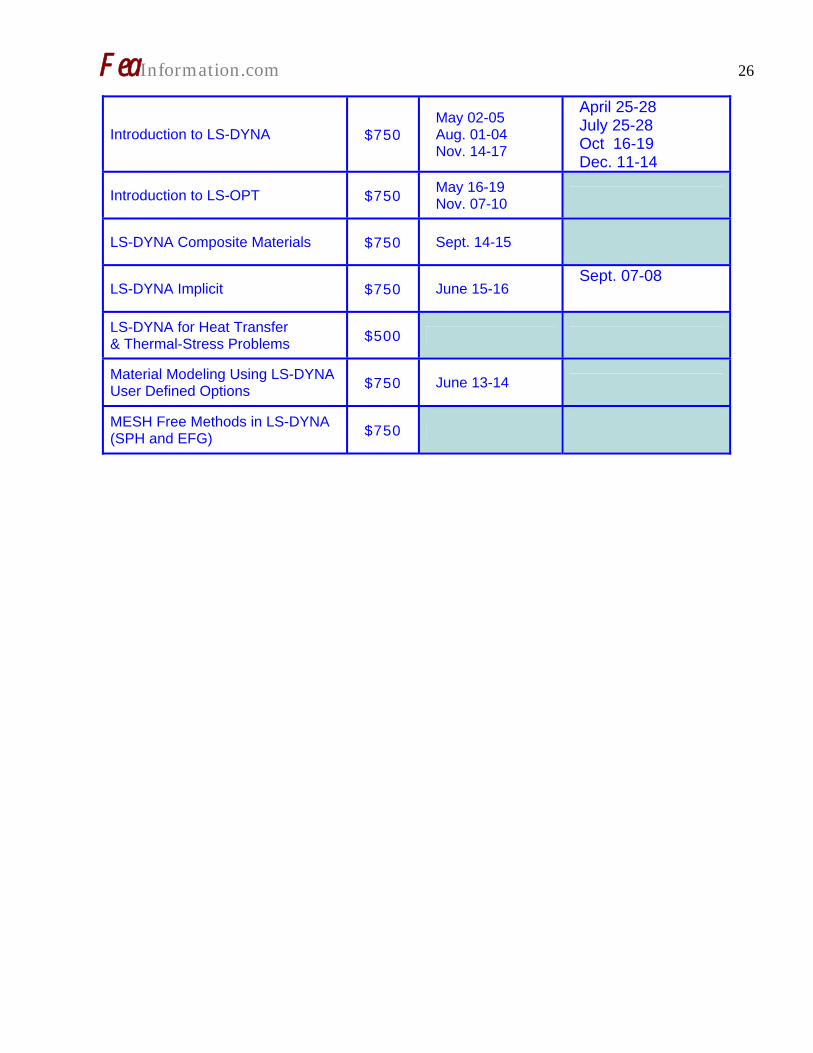
LSTC Training Classes – 2006
California Location
LSTC California 7374 Las Positas Road Livermore, CA 94551
Michigan Location
LSTC Michigan 1740 W. Big Beaver Rd Suite 100 Troy , MI 48084
LSTC Training Classes – 2006 - continued
Training Class US $ Livermore, CA Detroit, MI
Advanced LS-DYNA for Impact Analysis
$950 June 27-30 Sept 5-6
Advanced Options in LS-DYNA $750 August 15-16
ALE/Eulerian & Fluid/Structure Interaction in LS-DYNA $750 July 12-14
Concrete and Geomaterial Model-ing with LS-DYNA $750 Oct 24-25
Contact in LS-DYNA $750 Sept. 12-13 Aug 15-16
For Training Information: www.lstc.com [email protected] 925 449 2500
FeaInformation.com 26
Introduction to LS-DYNA $750 May 02-05 Aug. 01-04 Nov. 14-17
April 25-28 July 25-28 Oct 16-19 Dec. 11-14
Introduction to LS-OPT $750 May 16-19 Nov. 07-10
LS-DYNA Composite Materials $750 Sept. 14-15
LS-DYNA Implicit $750 June 15-16 Sept. 07-08
LS-DYNA for Heat Transfer & Thermal-Stress Problems $500
Material Modeling Using LS-DYNA User Defined Options $750 June 13-14
MESH Free Methods in LS-DYNA (SPH and EFG) $750
FeaInformation.com 27
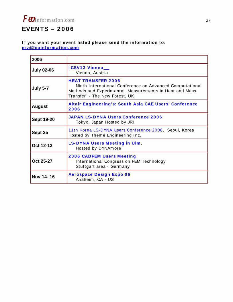
EVENTS – 2006 If you want your event listed please send the information to: [email protected]
2006
July 02-06 ICSV13 Vienna Vienna, Austria
July 5-7 HEAT TRANSFER 2006 Ninth International Conference on Advanced Computational Methods and Experimental Measurements in Heat and Mass Transfer - The New Forest, UK
August Altair Engineering’s: South Asia CAE Users’ Conference 2006
Sept 19-20 JAPAN LS-DYNA Users Conference 2006 Tokyo, Japan Hosted by JRI
Sept 25 11th Korea LS-DYNA Users Conference 2006, Seoul, Korea Hosted by Theme Engineering Inc.
Oct 12-13 LS-DYNA Users Meeting in Ulm. Hosted by DYNAmore
Oct 25-27 2006 CADFEM Users Meeting International Congress on FEM Technology Stuttgart area - Germany
Nov 14- 16 Aerospace Design Expo 06 Anaheim, CA - US

FeaInformation.com 28
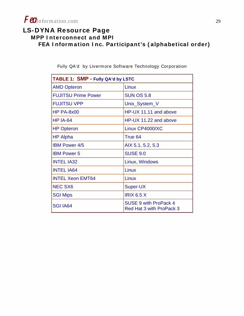
LS-DYNA Resource Page Interface - Hardware - OS And General Information Participant Hardware/OS that run LS-DYNA (alphabetical order). LS-DYNA has been fully QA’d by Livermore Software Technology Corporation for All Hardware and OS listed below.
TABLE 1: SMP TABLE 2: MPP Interconnect and MPI
TABLE 1: SMP - Fully QA’d by LSTC AMD Opteron Linux FUJITSU Prime Power SUN OS 5.8 FUJITSU VPP Unix_System_V HP PA-8x00 HP-UX 11.11 and above HP IA-64 HP-UX 11.22 and above HP Opteron Linux CP4000/XC HP Alpha True 64 IBM Power 4/5 AIX 5.1, 5.2, 5.3 IBM Power 5 SUSE 9.0 INTEL IA32 Linux, Windows INTEL IA64 Linux INTEL Xeon EMT64 Linux NEC SX6 Super-UX SGI Mips IRIX 6.5 X
SGI IA64 SUSE 9 with ProPack 4 Red Hat 3 with ProPack 3
FeaInformation.com 29
LS-DYNA Resource Page MPP Interconnect and MPI FEA Information Inc. Participant’s (alphabetical order)
Fully QA’d by Livermore Software Technology Corporation
TABLE 1: SMP - Fully QA’d by LSTC AMD Opteron Linux FUJITSU Prime Power SUN OS 5.8 FUJITSU VPP Unix_System_V HP PA-8x00 HP-UX 11.11 and above HP IA-64 HP-UX 11.22 and above HP Opteron Linux CP4000/XC HP Alpha True 64 IBM Power 4/5 AIX 5.1, 5.2, 5.3 IBM Power 5 SUSE 9.0 INTEL IA32 Linux, Windows INTEL IA64 Linux INTEL Xeon EMT64 Linux NEC SX6 Super-UX SGI Mips IRIX 6.5 X
SGI IA64 SUSE 9 with ProPack 4 Red Hat 3 with ProPack 3

FeaInformation.com 30
TABLE 2: MPP Interconnect and MPI Vendor O/S HPC Intereconnect MPI Software
AMD Opteron Linux InfiniBand (SilverStorm), MyriCom, QLogic InfiniPath
LAM/MPI, MPICH, HP MPI, SCALI
FUJITSU Prime Power SUN OS 5.8
FUJITSU VPP Unix_System_V
HP PA8000 HPUX
HPIA64 HPUX
HP Alpha True 64
IBM Power 4/5 AIX 5.1, 5.2, 5.3
IBM Power 5 SUSE 9.0 LAM/MPI
INTEL IA32 Linux, Windows InfiniBand (Voltaire), MyriCom
LAM/MPI, MPICH, HP MPI, SCALI
INTEL IA64 Linux LAM/MPI, MPICH, HP MPI
INTEL Xeon EMT64 Linux
InfiniBand (Topspin, Voltaire), MyriCom, QLogic InfiniPath
LAM/MPI, MPICH, HP MPI, INTEL MPI, SCALI
NEC SX6 Super-UX
SGI Mips IRIX 6.5 NUMAlink MPT
SGI IA64 SUSE 9 w/ProPack 4RedHat 3 w/ProPack 3
NUMAlink, InfiniBand, (Vol-taire)
MPT, Intel MPI, MPICH

FeaInformation.com 31
LS-DYNA Resource Page Participant Software Interfacing or Embedding LS-DYNA Each software program can interface to all, or a very specific and limited seg-ment of the other software program. The following list are software programs interfacing to or having the LS-DYNA solver embedded within their product. For complete information on the software products visit the corporate website. ANSYS - ANSYS/LS-DYNA www.ansys.com/products/environment.asp
ANSYS/LS-DYNA - Built upon the suc-cessful ANSYS interface, ANSYS/LS-DYNA is an integrated pre and postpro-cessor for the worlds most respected ex-plicit dynamics solver, LS-DYNA. The combination makes it possible to solve combined explicit/implicit simulations in a very efficient manner, as well as per-form extensive coupled simulations in Robust Design by using mature struc-tural, thermal, electromagnetic and CFD technologies.
AI*Environment: A high end pre and post processor for LS-DYNA, AI*Environment is a powerful tool for advanced modeling of complex struc-tures found in automotive, aerospace, electronic and medical fields. Solid, Shell, Beam, Fluid and Electromagnetic meshing and mesh editing tools are in-cluded under a single interface, making AI*Environement highly capable, yet easy to use for advanced modeling needs.
ETA – DYNAFORM www.eta.com Includes a complete CAD interface capa-ble of importing, modeling and analyz-ing, any die design. Available for PC, LINUX and UNIX, DYNAFORM couples af-fordable software with today's high-end, low-cost hardware for a complete and affordable metal forming solution.
ETA – VPG www.eta.com
Streamlined CAE software package pro-vides an event-based simulation solution of nonlinear, dynamic problems. eta/VPG's single software package over-comes the limitations of existing CAE analysis methods. It is designed to ana-lyze the behavior of mechanical and structural systems as simple as linkages, and as complex as full vehicles
MSC.Software “MSC.Dytran LS-DYNA” www.msc.software.com
Tightly-integrated solution that combines MSC.Dytran's advanced fluid-structure interaction capabilities with LS-DYNA's high-performance structural DMP within a common simulation environment. In-novative explicit nonlinear technology enables extreme, short-duration dynamic events to be simulated for a variety of industrial and commercial applications on UNIX, Linux, and Windows platforms. Joint solution can also be used in con-junction with a full suite of Virtual Prod-uct Development tools via a flexible, cost-effective MSC.MasterKey License System.

FeaInformation.com 32 Side Impact With Fuel Oil Inside MSC.Software - MSC.Nastran/SOL 700 The MSC.NastranTM Explicit Nonlinear product module (SOL 700) provides MSC.Nastran users the ability access the explicit nonlinear structural simulation capabilities of the MSC.Dytran LS-DYNA solver using the MSC.Nastran Bulk Data input format. This product module offers unprecedented capabilities to analyze a variety of problems involving short dura-tion, highly dynamic events with severe geometric and material nonlinearities. MSC.Nastran Explicit Nonlinear will allow users to work within one common mod-eling environment using the same Bulk Data interface. NVH, linear, and nonlin-ear models can be used for explicit appli-cations such as crash, crush, and drop test simulations. This reduces the time required to build additional models for another analysis programs, lowers risk due to information transfer or translation issues, and eliminates the need for addi-tional software training. MSC.Software – Gateway for LS-DYNA Gateway for LS-DYNA provides you with the ability to access basic LS-DYNA simulation capabilities in a fully inte-grated and generative way. Accessed via a specific Crash workbench on the GPS workspace, the application enhances
CATIA V5 to allow finite element analysis models to be output to LS-DYNA and then results to be displayed back in CATIA. Gateway for LS-DYNA supports explicit nonlinear analysis such as crash, drop test, and rigid wall analysis.
Gateway products provide CATIA V5 us-ers with the ability to directly interface with their existing corporate simulation resources, and exchange and archive as-sociated simulation data.

FeaInformation.com 33 Oasys software for LS-DYNA www.arup.com/dyna Oasys software is custom-written for 100% compatibility with LS-DYNA. Oasys PRIMER offers model creation, editing and error removal, together with many specialist functions for rapid generation of error-free models. Oasys also offer post-processing software for in-depth analysis of results and automatic report generation.
EASi-CRASH DYNA http://www.esi-group.com/SimulationSoftware/EASi_CRASH-DYNA/ EASi-CRASH DYNA is the first fully inte-grated environment for crashworthiness and occupant safety simulations with LS-DYNA, and covers the complete CAE-process from model building and dataset preparation to result evaluation and design comparisons. EASi-CRASH DYNA can be used for con-cept crash, FE crash and coupled rigid body/FE crash simulations in conjunction with MADYMO. EASi-CRASH DYNA’s main features in-clude:
• Support of all keywords of LS-DYNA 970/971
• Powerful mesh editing features, such as automesh and remesh
• LS-DYNA/MADYMO coupling capa-bilities for pre- and post processing (support of MADYMO format till ver-sion 6.2.2)
• Model Assembler for organizing the model through sub assembly/sub models and included files
• Enhanced Weld tools for manipula-tion of connections and Weld com-parison
• Simple dummy positing and seat belt routing
• Pre and Post processing in same environment
• Superpose and merge multiple models
• Animation and plotting • Process compatible • Full capability to handle IGES,
CATIA V4, CATIA V5, UG and NASTRAN files

FeaInformation.com 34
Hardware - Computing - Communication Products
www.amd.com
www.fujitsu.com
www.hp.com
www.ibm.com/servers/deepcomputing
www.intel.com
www.nec.com
www.sgi.com
www.pathscale.com
www.microsoft.com
FeaInformation.com 35
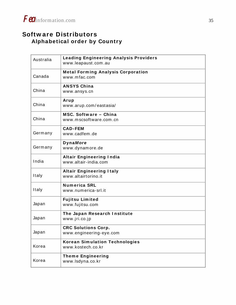
Software Distributors Alphabetical order by Country
Australia
Leading Engineering Analysis Providers www.leapaust.com.au
Canada Metal Forming Analysis Corporation www.mfac.com
China ANSYS China www.ansys.cn
China Arup www.arup.com/eastasia/
China MSC. Software – China www.mscsoftware.com.cn
Germany CAD-FEM www.cadfem.de
Germany DynaMore www.dynamore.de
India Altair Engineering India www.altair-india.com
Italy Altair Engineering Italy www.altairtorino.it
Italy Numerica SRL www.numerica-srl.it
Japan Fujitsu Limited www.fujitsu.com
Japan The Japan Research Institute www.jri.co.jp
Japan CRC Solutions Corp. www.engineering-eye.com
Korea Korean Simulation Technologies www.kostech.co.kr
Korea Theme Engineering www.lsdyna.co.kr

FeaInformation.com 36
Software Distributors (cont.) Alphabetical order by Country
Netherlands
Infinite Simulation Systems B.V www.infinite.nl
Russia
Strela, LLC www.ls-dynarussia.com
Sweden
Engineering Research AB www.erab.se
Taiwan
Flotrend www.flotrend.com.tw
USA
Engineering Technology Associates www.eta.com
USA
Dynamax www.dynamax-inc.com
USA
Livermore Software Technology Corp. www.lstc.com
UK
Oasys, LTD www.arup.com/dyna/

FeaInformation.com 37
Consulting and Engineering Services Alphabetical Order By Country Australia Manly, NSW www.leapaust.com.au
Leading Engineering Analysis Providers Greg Horner [email protected] 02 8966 7888
Canada Kingston, Ontario www.mfac.com
Metal Forming Analysis Corporation Chris Galbraith [email protected] (613) 547-5395
India Bangalore www.altair-india.com
Altair Engineering India Nelson Dias [email protected] 91 (0)80 2658-8540
Italy Torino www.altairtorino.it
Altair Engineering Italy [email protected]
Italy Firenze www.numerica-srl.it
Numerica SRL [email protected] 39 055 432010
UK Solihull, West Midlands www.arup.com
ARUP Brian Walker [email protected] 44 (0) 121 213 3317
USA Austin, TX
KBEC L.C Khanh Bui [email protected] (512) 363-2739
USA Windsor, CA www.schwer.net/SECS
SE&CS Len Schwer [email protected] (707) 837-0559
USA Corvallis, OR www.predictiveengineering.com
Predictive Engineering George Laird (1-800) 345-4671 [email protected]
USA Neenah, WI www.structuretechnology.com
Structure Incorporated Todd L. Peters (920) 722 7060 [email protected]

FeaInformation.com 38
Educational & Contributing Participants Alphabetical Order By Country China
Dr. Quing Zhou Tsinghua University
India
Dr. Anindya Deb Indian Institute of Science
Italy
Professor Gennaro Monacelli
Prode – Elasis & Univ. of Napoli, Frederico II
Russia Dr. Alexey I. Borovkov St. Petersburg State Tech. University
USA Dr. Ted Belytschko Northwestern University
USA Dr. David Benson University of California – San Diego
USA Dr. Bhavin V. Mehta Ohio University
USA Dr. Taylan Altan The Ohio State U – ERC/NSM
USA Dr. Ala Tabiei University of Cincinnati

FeaInformation.com 39
FEA Information China Participants Software, Hardware, Training, Consulting, Services
Altair Engineering Software (Shanghai) Co., Ltd.
Herbert Qi Tel: +86 (0)21 5393 0011 Website: www.altair.com.cn Contact: [email protected] Contact: [email protected])
Ansys-China, Inc.
Tel: 86-10-84085558 Website: www.ansys.com.cn Contact: [email protected]
Oasys Software for LS-DYNA
Kimbal Virdi Tel: +86 21 5396 6633 Contact: [email protected] Website: www.arup.com/dyna
Beijing Yuntong Forever CPC. Co. Ltd.
Tel: +86-10-82561200/01/03 Website: http://cpc.ytforever.com Sole Distributor of LINUX NETWORX, INC. (USA) in China Contact: [email protected]
Engineering Technology Asso-ciates (China) Inc.
Martin Ma Tel: + 86-21-64385725 Contact: [email protected]
Hewlett-Packard Asia Pacific Ltd.
Jerry Huang Tel: +86-10-65645261 Contact: [email protected]
IBM China
Ms. Ling WANG - Tel: +86-10-6539-1188 x4463 (T/L:901-4463) Website: http://www.ibm.com/cn/ Contact: [email protected]
MSC. Software Corp.
Tel: +86-10-6849-2777 Website: www.mscsoftware.com.cn Contact: [email protected]

FeaInformation.com 40
FEA Information China Participants Software, Hardware, Training, Consulting, Services
SGI China
Carl Zhang Tel: +86 -10 - 65228868 Ext. 3362 Contact: [email protected]
Tsinghua University
Qing Zhou, PhD. - Professor Department of Automotive Engineering Beijing, 100084, China
Zhongfang Information Technology Ltd
Larry Liang Tel: +86-21-54973162 Website: http://www.cntech.com.cn Contact: [email protected]
Zhong Guo ESI Co., Ltd
Yang Xiaojum Phone: +86 (020) 8235 6272 Contact : Yang Xiaojun

FeaInformation.com 41
Informational Websites The LSTC LS-DYNA Support site: www.dynasupport.com
LSTC LS-DYNA Support Site
www.dynasupport.com
FEA Informationwebsites
www.feainformation.com
TopCrunch – Benchmarks
www.topcrunch.org
LS-DYNA Examples (more than 100 Examples)
www.dynaexamples.com
LS-DYNA Conference Site
www.ls-dynaconferences.com
LS-DYNA Publications to Download On Line
www.dynalook.com
LS-DYNA Publications
www.feapublications.com
LS-DYNA CADFEM Portal
www.lsdyna-portal.com.

FeaInformation.com 42 The following publication in it’s entirety is on line at: www.crashoptimization.com
New Features in LS-OPT® Version 3
Nielen Stander and Willem Roux Livermore Software Technology Corporation
Abstract An overview of LS-OPT features is given with special emphasis on new features available in LS-OPT Version 3.1. The main features added to Version 3 include discrete optimization, 3-D metamodel plotting, additional statistics features, and a simplification of parameter identi-fication. LS-OPT is now available for MS Windows®. Introduction and Overview In today’s CAE environment it is unusual to make engineering decisions based on a single physics simulation. A typical user conducts multiple analyses by vary-ing the design and uses the combined results for design improvement. LS-OPT [1] provides an environment for design and is tightly interfaced to LS-DYNA and LS-PREPOST with the goal of allowing the user to organize input for multiple simulations and gather and display the results and statistics. More specifically, LS-OPT has capabilities for improving de-sign performance in an uncertain envi-ronment and conducting system and ma-terial identification. These objectives can be achieved through the use of statistical tools and optimization. The individual tasks that can thus be accomplished are:
• Identify important design variables • Optimize the design • Explore the design space using
surrogate design models
• Identify sources of uncertainty in FE models
• Visualize statistics of multiple runs The typical applications are: Multidisci-plinary Design Optimization (crashwor-thiness, modal analysis, durability analy-sis, etc.), system and material identifica-tion (biomaterials, metal alloys, con-crete, airbag properties, etc.) and proc-ess design (metal forming). The main technologies available in LS-OPT are:
• Experimental Design (DOE). D-Optimal design, Latin Hypercube sampling, Space Filling and others. DOE allows the user to automati-cally select a set of different de-signs to be analyzed. The main types mentioned here are each suited to a different type of analy-sis: D-Optimal for polynomials and sequential optimization, Latin Hy-percube for stochastic analysis and Space Filling for Neural Networks.
• Metamodels (approximations). Re-sponse Surface Methodology and Neural Networks are the most im-portant. With these tools, the user can explore the design space and quantify the predictability of a re-sponse, i.e. identify sources of noisy response.
FeaInformation.com 43 • Variable screening [4] provides in-
formation on the relative impor-tance of design variables.
• Probabilistic analysis includes Reli-ability and Outlier Analysis [3]. The former allows the user to evaluate the probability of failure while the latter allows the identifi-cation of parts of a model that contribute to noisy response and therefore affect the predictability of the results. The outlier analysis uses integrated LS-PREPOST fea-tures.
• Optimization. Used for automated design improvement. The Succes-sive Response Surface Method (SRSM) [5] is the principal itera-tive tool for finding a converged optimum. A similar methodology is used for finding a converged result using neural net updating.
Features are available to distribute simu-lation jobs across a network, using a queuing system.