Embed Size (px)
Citation preview
As in International Journal of Impact Engineering, 25 (2008) 1087- 1101 1087
Finite-element analysis of bicycle helmet oblique impacts
N.J. Mills* and A. Gilchrist Metallurgy and Materials, University of Birmingham, Birmingham B15 2TT, UK Received 25 November 2005, received in revised form 5 February 2007, accepted 24 may 2007 * corresponding author [email protected]
_________________________________________________________________________________________
Abstract
Finite Element Analysis (FEA) was performed for bicycle helmets making oblique impacts with a road surface, to evaluate the linear and rotational accelerations of the headform. Helmet rotation on the head was considered, modelling the helmet and retention strap interactions with the headform. The effects of frictional parameters on the response were explored, and parameters selected to reproduce experimental results. Predictions were made for two helmets, for a range of impact locations and tangential velocities. The design method for the peak headform linear acceleration was confirmed; it was hardly affected by the tangential component of the impact velocity. The peak headform rotational acceleration was investigated as a function of the helmet geometry, impact sites and velocities and the contributing mechanisms established. Keywords: bicycle, helmet, impact, foam, FEA __________________________________________________________________________________________
1. Introduction
This paper uses finite-element analysis (FEA) to investigate three scientific issues related to bicycle helmet oblique impacts. These issues also apply to impacts on other protective foam products, such as hip protectors for the elderly, and sport protective garments.
(a) How, in a system having two concentric sliding
interfaces, are the impact forces related to the interface frictional parameters?
There can be slip or stick (hence rolling) at the helmet shell/ road and headform/ helmet interfaces. As no prior research could be found on headform/helmet interface conditions, they were empirically modified to replicate experimental data [1] of road forces and head accelerations vs. time. In general the protector has a much smaller mass and angular inertia than the protected body part; a typical helmet has 4% of the mass and 7% of the angular inertia of a head. Consequently, the forces required to accelerate the
helmet are much smaller than those to accelerate the head. b) What geometric factors affect the rotation of a foam
protective product on part of a human body? The skull acts as a nearly-rigid body, with the scalp and
hair acting as thin, deformable layers on its nearly-spherical surface. Consequently, helmets differ from hip protectors, where the head of the femur is buried in the soft tissue of the thigh. Helmet fit affects helmet rotation on the head in an impact. Many bicycle helmets have a single liner size, with a headband circumference that adjusts to the wearer’s head [1]. Due to the wide range of human head length-to-width ratios [2], for many cyclists their head shape does not match their helmet interior shape. The tightness of the chin strap under the chin affects motorcycle helmet retention [3], so may affect bicycle helmet retention. That research showed that nape straps resist forward helmet rotation, while straps running towards the front of the helmet resist rearward helmet rotation on the head. If helmet rotations at the end of the experimental oblique impacts [1] can be reproduced, the approaches of this and the prior section are confirmed.

As in International Journal of Impact Engineering, 25 (2008) 1087- 1101 1088
(c) Do ventilation holes in a complex-shaped product
invalidate the design calculation method for headform linear acceleration, especially for oblique impacts?
An analysis for the headform linear acceleration, when a bicycle helmet without ventilation holes [4] makes an impact normal to a road surface, simplified the head geometry as being locally spherical, and treated the head and road surfaces as being rigid. It ignored the helmet shell, and assumed the cross-sectional area of the crushed foam region is the same as the contact area between the helmet and the road. As 1990 era helmets had few, small ventilation holes, it was reasonable to ignore their existence. The impact force vs. foam deflection relationship was predicted to be linear, with a ‘loading slope’ proportional to the initial foam yield stress and to the mean helmet radius of curvature at the impact site. Given the vertical (normal) impact velocity, the required loading slope can be calculated, hence the foam yield stress and thickness determined. Experiments showed a linear response, but the predicted slope was in error by 30 to 50%. FEA is performed here for helmets with ventilation holes making oblique impacts. If the headform linear acceleration is still a linear function of the liner compressive deformation, the basic design method is confirmed. No previous publications on FEA of bicycle helmet oblique impacts could be found.
If the first two questions can be answered, FEA of
bicycle helmet oblique impacts can be validated by comparison with experimental results. It should be possible to explain details of experimental oblique impact tests, and why relatively high headform rotational accelerations occur during some direct impacts. The effects of higher tangential velocities on the headform response can then be explored.
The helmet and headform geometries are considered ahead of FEA material models. The reasons for modelling a free headform a free headform, rather than a whole body, were explained in [1].
2 Geometry of helmet, headform and straps 2.1 Helmets
Dr Brühwiler of EMPA, St Gallen, Switzerland,
provided the scanned shapes of a Specialised S1 bicycle helmet (Figure 1), used for ventilation research [5], and a headform. The helmet had 24 ventilation holes of variable size and shape. The .stp file used 148000 triangular facets to describe the helmet surface. The CAD programme Rhino was used to reduce the number of facets to 2500, and their aspect ratio to < 2:1, to allow reasonably fast FEA. An exported ACIS .sat file was imported to ABAQUS as a 3D solid part, representing the helmet liner. A copy of this part was converted to a shell, and internal sections removed, leaving an approximation of the real helmet shell. A
simpler helmet geometry was constructed by approximating in Rhino the inner and outer surfaces of the S1 helmet with sections of ellipsoids, then adding 27 elliptical holes. When its surface geometry was reduced to 2500 triangles, the initially smooth surfaces became facetted (Figure 2). Its geometry is an approximation to the some of the cheaper helmets tested [1].
Table 1 lists geometrical parameters of two helmets. Typical bicycle helmets have a length, at the lower edge, of 220 to 230 mm, and a width of 175 to 180 mm. The model 27-hole and Specialised helmets have respectively 220 mm and 230 mm internal lengths, the latter being the length of the real S1 helmet. There is usually a 3 or 4 mm gap between the headform and the liner interior surface at the start of the simulations; the real helmet has pads of soft polyurethane open-cell (comfort) foam in this space. Figure 3, the equivalent of a shadow X-ray, shows the near-uniform gap between the head and helmet in a vertical section. The helmet locations (or impact sites) in Table 1 are defined by rotations from the crown-on-road position shown in figure 4. The ‘front 90°’ position is reached by a 90° rotation of the helmet and head about the 1 axis, while the right 70° position is reached by a 70° rotation about the 3 axis.
2.2 Headforms
Hollow aluminium headforms, having a higher bending
stiffness than the human skull, are used for EN 1078 [6] helmet testing. Their mass increases, from 4.1 kg for a 540 mm circumference to 5.6 kg for a 600 mm circumference. The Ogle headform used for helmet testing [1] had an approximately 10 mm thick plasticized PVC scalp stimulant outside the aluminium casting. The response of a 100 mm long scalp section was measured under plane strain compression conditions, with a 10 mm wide, long flat steel anvil pressing on the upper surface, and a flat steel table underneath. In the Specialized helmet circa 10 mm wide EPS bands press on the head, explaining the conditions of the compression test. The compressive stress vs. deflection graph up to a stress of 11 MPa was approximated by linear segments (Table 2) and used as the normal contact stiffness function of the head/helmet interface. This obviated the need to create and mesh the scalp geometry. The scalp layer shear stiffness was measured in a slow shear test as 2.3 x 10⁸ Pa m-1, the value being used in the FEA as the interface ‘elastic slip stiffness’.
The scanned headform was scaled to have a length (Table 3 of [1]) similar to that of the Ogle headform. The headform was treated as a rigid shell, with an internal strip extending to the location of the centre of gravity (CG) of the Ogle headform. A 4.26 kg point mass, and moments of inertia equal to those of the Ogle headform, were allocated to a reference point at the CG. The scalp on the headform provides its biofidelity (see later), while the rigid nature of the headform prevents internal vibrations. The headform axes are: x nose to occiput, y ear to ear, z neck to crown (Figure 4).
As in International Journal of Impact Engineering, 25 (2008) 1087- 1101 1089
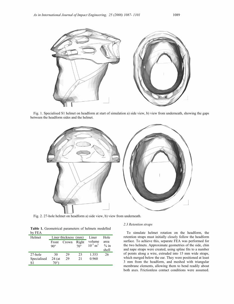
Fig. 1. Specialised S1 helmet on headform at start of simulation a) side view, b) view from underneath, showing the gaps
between the headform sides and the helmet.
Fig. 2. 27-hole helmet on headform a) side view, b) view from underneath.
Table 1. Geometrical parameters of helmets modelled by FEA
Liner thickness (mm) Helmet Front 90°
Crown Right 70°
Liner volume 10-3 m3
Hole area % in shell
27-hole 30 29 23 1.353 26 Specialised S1
24 (at 70°)
29 21 0.960
2.3 Retention straps
To simulate helmet rotation on the headform, the retention straps must initially closely follow the headform surface. To achieve this, separate FEA was performed for the two helmets. Approximate geometries of the side, chin and nape straps were created, using spline fits to a number of points along a wire, extruded into 15 mm wide straps, which merged below the ear. They were positioned at least 3 mm from the headform, and meshed with triangular membrane elements, allowing them to bend readily about both axes. Frictionless contact conditions were assumed.

As in International Journal of Impact Engineering, 25 (2008) 1087- 1101 1090
Fig. 3. Wireframe side view of the near-uniform gap between the meshed S1 helmet and headform, at the start of a simulation.
Fig. 4. Schematic of the headform and rig axes, and headform velocity vector.
Table 2. Normal contact response of the PVC scalp simulant
pressure MPa
Over-closure mm
0 0 0.63 1 2.22 2 4.6 3 7.8 4
11.2 4.8 The tops of the two side-straps were attached to one
‘skyhook’ plate and the top of the nape strap to another. These plates, of mass 100 g, were given an initial upwards motion of 5 to 7 ms-1. Inspection of the output file revealed when the straps contacted the chin and headform sides, and the maximum tensile stress ≅ 10 MPa. This deformed strap shape was used as an orphan mesh in the main FEA. As the side straps typically pass through helmet liners 50 mm above its lower edge [1],
for the 27-hole helmet nodes on the straps, close to that position, were tied to liner inner surface.
The retention strap geometry was typical, rather than being optimised to reduce helmet rotation. The position of the chin, side and nape strap junction, well below the axis of helmet-on-head rotation, is known [3] to be effective in limiting helmet rotation about an ear-to-ear axis.
3. Contact conditions The penalty friction formulation used allows elastic slip
(shear of the interface before slip occurs) to simulate the shear of the scalp layer. The stiffness function normal to the headform/liner interface (Table 2) simulated the compressive response of the scalp. When the headform was dropped by 200 mm onto a rigid flat surface, FEA predicted a peak linear headform acceleration of 145 g at the right 70° site and 170 g at the crown site. The peak over-closures of the head and road (representing the scalp compression) were 3.8 mm and 4.1 mm respectively at the two sites. In headform development [7], such a drop at a right 35° site should cause a peak acceleration between 100 and 150 g. Hence the FEA model just meets this condition.
If ‘hard’ contact was used at the road/shell interface, force oscillations of up to 1 kN amplitude tended to hide the underlying response. At this interface, the normal pressure was set at 10 MPa at a 1 mm over-closure and 100 MPa at 2 mm over-closure. This reduced force oscillations to an acceptable level, while the <1 mm peak over-closure was insignificant. The tangential frictional parameters were selected later to reproduce experimental data.
The helmet shell inner surface was tied to the liner outer surface, simulating in-mould bonding, as used in the S1 and other helmets. However, if a kinematic contact algorithm was used between the shell and the road, the tie was ignored after contact occurred, allowing the liner to cross the road surface (by a zero amount at the edge of the contact area, but up to 5 mm at its centre for the 27 hole helmet). Consequently, a

As in International Journal of Impact Engineering, 25 (2008) 1087- 1101 1091
penalty contact algorithm was used for this interface, but a kinematic contact algorithm for the other interfaces. 3.1. Impact sites and velocities
The test rig coordinate system (figure 4) has a 2 axis
normal to the road surface, and 3 axis parallel to the headform tangential velocity component. The headform positions and velocities replicated the testing conditions [1]. A crown impact site, although uncommon in accidents, was also chosen. For this, the helmet was assumed to be moving sideways relative to the road, induces a third axis of helmet rotation on the head.
3.2 Meshing
The part meshes were seeded at 8 to 10 mm spacing.
The S1 (27-hole) helmet liner had 7943 (7976) modified 10-node quadratic tetrahedral elements C3D10M, the shell 2274 (1065) linear triangular shell elements S3R, the strap system 401 linear triangular membrane elements M3D3, while the headform had 8992 linear rigid triangular elements R3D3. The region around critical elements, that require the smallest stable time intervals was re-meshed, after faces were merged using virtual topology, to ensure the time interval exceeded 50 ns. This allows a reasonable CPU time of about 10 hours for the S1 helmet. Distortion control was used with the liner elements; this option aims to prevent crushable foams elements inverting. The length ratio parameter was given the default value of 0.1.
4. Material models
3.1 Expanded polystyrene (EPS) foam Previous FEA [8] considered extruded polystyrene
(XPS) foam of density 35 kg m-3, using the Crushable Foam model in ABAQUS for isotropic materials. The yield surface, which describes the stress states that cause yielding, has equation
( ) 222
21 a
bappp e
tc =
+
−−
σ (1)
where σe is the von Mises equivalent stress, and p is
the hydrostatic pressure component of the stress tensor. The section of the yield surface in the p σe plane is an ellipse, with half axes a and b in the p and σe directions respectively. The ellipse intercepts the p axis at - pt and pC0, respectively the initial yield pressures in hydrostatic tension and compression. When the foam volume reduces, it hardens, and the ellipse increases in size while maintaining the same axial ratio; the p axis intercept at -pt remains fixed, while that at the right moves to pC.
The parameters used are σC0 / pC0 and pt / pC0 followed by tabular hardening data for σC versus the true compressive inelastic strain εTi. σC0 is the initial yield stress in uniaxial compression. The hydrostatic compression yield stress pC0 of EPS, measured at moderate strain rates by Masso-Moreu and Mills [9], supported the previously used σC0 / pC0 = 1.933. The same ratio was assumed to apply to higher density EPS. It is impossible to measure pt, since the sudden application of a vacuum, equivalent to applying a hydrostatic tensile stress of 0.1 MPa, does not cause yield. The uniaxial tensile failure stress of EPS is related to the bead boundary tensile strength; in general it exceeds σC0 [10]. Therefore, although the ABAQUS manual suggests using pt / pC0 = 0.05, the previously used value of 1.0 [8] was adopted.
Bicycle helmets contain EPS mouldings [1] of density in the range 71 to 101 kg m-3. Their uniaxial compressive response on loading can be fitted with
RP
CC −−+=
εεσσ
10
0 (2)
where σC is the compressive stress, ε the strain, P0 the effective gas pressure in the cells, and R the foam relative density (calculated by dividing the EPS density by the 1050 kg m-3 density of solid polystyrene). EPS of 83 kg m-3 density was used for the majority of simulations. A table of σC values was computed from equation (2), using the parameters in Table 3 [11] at intervals of compressive true strain of 0.06. The compressive true strain is defined by λε ln−=T (3) where λ is the extension ratio in the compression direction. As only 15 mm tall samples could be cut from the S1 helmet liner, their compressive yield stress was measured at a low strain rate with an Instron machine; however the yield stress of EPS is insensitive to strain rate.
The default material damping parameter of 0.05 in ABAQUS was used for the EPS and the shell material.
Table 3. EPS properties used in the FEA
Density kg m-3
Young’s modulus E MPa
initial yield stress σC0
MPa
effective gas pressure P0 MPa
35 10 0.29 0.15 55 20 0.6 0.20 83 40 1.10 0.27 101/98 59* 1.30 0.27
*taken from [12] 4.2 Retention straps
A 25 cm length of polyethyleneterephthalate (PET) chin
strap webbing from a bicycle helmet was tested in tension with an Instron machine. After the initial curved response for forces < 100 N, the loading response was linear with tensile stiffness 82 kN m-1. To achieve the same tensile stiffness for webbing of thickness of 1.3 mm and width 15 mm, a material model Young’s modulus of 1.0 GPa was used. In compression or bending the webbing has negligible stiffness. Although two webbing straps run below the chin, from the
As in International Journal of Impact Engineering, 25 (2008) 1087- 1101 1092
junctions below the ears, these were treated as a single strap for modelling.
4.3 Shell
The thermoplastic shell was assigned a Young’s
modulus of 3 GPa, a Poisson’s ratio of 0.4 and an initial tensile yield stress of 60 MPa, which increases to 70 MPa at a strain of 1.0, data typical for polycarbonate [13]. The shell was 0.4 mm thick, typical for bicycle helmets [1], and integration was used at 5 points through the element thickness.
5. Preliminary FEA and validation
5.1 Effect of friction parameters on the response of the 27 hole helmet
Interfacial parameters were kept simple, so they could
be related to physical deformation mechanisms. Three types of data comparison were made for selecting interface parameters: (a) Evaluating road interface friction by matching road forces
Normal FN and tangential FT forces act at the road/shell interface. In experiments [1] FT / FN remained nearly constant at 0.21 ±0.03. An elastic slip stiffness was not used, as this interface lacks an easily-sheared elastic layer. Predictions were made of the variation of FT vs. FN , then a straight line fitted to the data.
(b) Evaluating head/helmet interface friction by matching headform accelerations
The road frictional force FT is largely transmitted, via the head/liner interface, to contribute to the headform rotational acceleration component 1θ&& . Offsets of the headform CG from the line of action of FN add to this, and cause other rotational acceleration components. The magnitude of the head rotational acceleration was plotted against the magnitude of its linear acceleration a , as in figure 5a. (c) Correlating the road frictional force to the headform rotational acceleration
Since the helmet inertia is small compared with that of the headform, the road frictional force FT is likely to correlate with the headform rotational acceleration component 1θ&& . Table 4 shows that the correlation coefficient r ranges from 0.84 to 0.99.
An investigation was made for the 27 hole helmet, with its
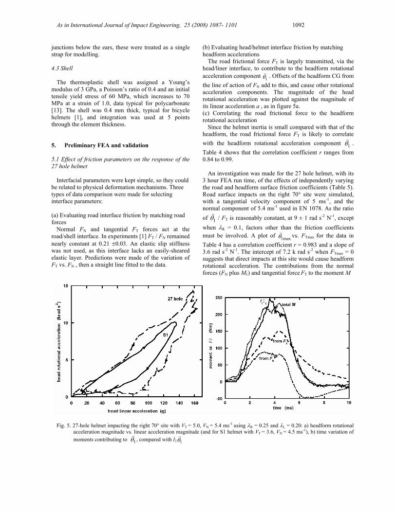
3 hour FEA run time, of the effects of independently varying the road and headform surface friction coefficients (Table 5). Road surface impacts on the right 70° site were simulated, with a tangential velocity component of 5 ms-1, and the normal component of 5.4 ms-1 used in EN 1078. As the ratio of 1θ&& / FT is reasonably constant, at 9 ± 1 rad s-2 N-1, except when λR = 0.1, factors other than the friction coefficients must be involved. A plot of max1θ&& vs. FTmax for the data in Table 4 has a correlation coefficient r = 0.983 and a slope of 3.6 rad s-2 N-1. The intercept of 7.2 k rad s-2 when FTmax = 0 suggests that direct impacts at this site would cause headform rotational acceleration. The contributions from the normal forces (FN plus M1) and tangential force FT to the moment M
Fig. 5. 27-hole helmet impacting the right 70° site with VT = 5.0, VN = 5.4 ms-1 using λR = 0.25 and λL = 0.20: a) headform rotational acceleration magnitude vs. linear acceleration magnitude (and for S1 helmet with VT = 3.6, VN = 4.5 ms-1), b) time variation of moments contributing to 1θ&& , compared with I1 1θ&&

As in International Journal of Impact Engineering, 25 (2008) 1087- 1101 1093
Table 4. Effects of friction coefficients on response parameters, for oblique impacts of 27 hole helmet on the right 70° site with VN = 5.4, VT = 5.0 ms-1
λR λH FT / FN (r) 1θ&& / FT (r)
rad s-2 N-1 1θ&& /a (r)
rad s-2 g-1 FTmax kN
1θ&&
max krad s-2
0.1 0.1 0.092 (0.997) 13.0 (0.915) 51 (0.914) 0.69 9.8 0.1 0.2 0.093 (0.997) 13.5 (0.919) 53 (0.909) 0.72 9.6 0.1 0.3 0.093 (0.997) 13.9 (0.920) 54 (0.904) 0.75 9.9 0.2 0.1 0.182 (0.998) 9.1 (0.911) 69 (0.908) 1.30 11.5 0.2 0.2 0.184 (0.995) 9.5 (0.931) 70 (0.887) 1.39 12.5 0.2 0.3 0.183 (0.993) 9.5 (0.941) 70 (0.899) 1.46 12.4 0.25 0.2 0.232 (0.991) 8.5 (0.931) 78 (0.887) 1.68 13.7 0.3 0.1* 0.155 (0.922) 9.7 0.905) 71 (0.993) >1.5 0.3 0.2 0.261 (0.985) 7.9 (0.922) 81 (0.884) 1.92 13.6 0.3 0.3 0.285 (0.959) 8.1 (0.961) 79 (0.865) 2.07 15.5 0.4 0.1* 0.143 (0.924) 10.2 (0.904) 69 (0.990) 0.4 0.2* 0.201 (0.959) 9.3 (0.945) 80 (0.996) 0.4 0.3 0.289 (0.919) 7.9 (0.962) 87 (0.834) 2.35 15.3 0.4 0.4 0.294 (0.822) 7.9 (0.984) 90 (0.754) 2.50 17.9
*stops just before peak load
Table 5. Parameter optimization for S1 helmet containing EPS of density 101 kg m-3 Right 70° impact at VN = 4.5, VT = 3.6 m s-1 λR λH Scalp
τmax kPa
Scalp elastic slip stiff MPa m-1
FNmax kN
FTmax kN
- max1θ&& krad s-2
max2θ&& krad
FT (r) FN 1θ&& /a (r)
rad s-2 g-1
1.2* 0.6* 500* 5.0* 6.05 0.59 6.1 -0.5 0.02 (0.29) 42 (0.99) 0.25 0.20 50 230 5.93 0.72 9.2 -0.4 0.08 (0.70) 45 (0.99) 0.25 0.20 ∞ 230 6.0 1.07 9.2 -0.9 0.18 (0.98) 65 (0.94) Experimental data 5.9 0.7 6.1 3.7 0.18 (0.95) 38(0.90)
* used in [14] about the 1 axis through the head CG were
calculated from the position of the headform CG relative to the road reference point (figure 4), and the reaction moment M1 and forces at this reference point. In figure 5b their time variation and total are compared with the product I1 1θ&& (for the initial headform position I1 was computed as 179.8 kg cm2). The moment from FT only caused about 60% of peak rotational head acceleration 1θ&& , but the total
moment is a good approximation to I1 1θ&& . The
imperfect correlation (Table 4) between FT and 1θ&& is due to their different time variation. The longer positive duration of the ‘moment from FT’ peak, compared with the ‘moment from FN’ peak, mirrors the longer duration of the experimental linear acceleration peaks, compared with the angular acceleration peaks (figure 8a of [1]).
Geometry influences the head rotational acceleration; the helmet exterior is convex, while for the right 70° site, the shape of the helmet interior, perpendicular to its axis of rotation, is oval. When the helmet rotates relative to the headform, a region further back than the helmet/road contact patch, comes into contact with the headform. This causes an uneven distribution of pressure on the headform surface (described later), increasing 1θ&& while the road reaction force FN is rising.
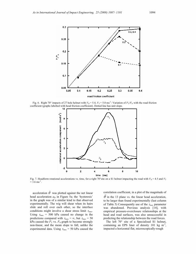
Figure 6 shows FT /FN is initially 93% of road friction coefficient λR, but becomes lower when λR -λH > 0.1. When λH << λR, it falls towards λH. When the helmet shell stops slipping on the road, FT falls slightly below the value of λR FN. The correlation coefficient between FT and FN falls when λH << λR , as the response becomes less linear and more hysteresis occurs on unloading. To match the experimental FT /FN data, the road surface friction coefficient λR ≅ 0.25. Reducing the head surface friction coefficient λH below 0.2 has little effect on the peak headform rotational acceleration. Consequently λH = 0.2 was used in the main set of simulations. The correlation coefficient between 1θ&& and a is high but not perfect, and the ratio of these variables remains almost constant when the friction coefficients change. When a similar impact was performed at a site with a smaller helmet radius of curvature (sideways at the front 70° site) the value of 1θ&& /a was nearly the same. Hence the helmet radius of curvature at the impact site appears to have little effect on the ratio.
5.2 Validation by comparison with S1 oblique impact data
For the S1 helmet, a comparison was made of FEA using friction coefficients λR = 0.25 and λH = 0.2 (Table 5), with experimental data in figure 10 of [1]. The magnitude of the total head rotational
As in International Journal of Impact Engineering, 25 (2008) 1087- 1101 1094
Fig. 6. Right 70° impacts of 27 hole helmet with VN = 5.4, VT = 5.0 ms-1: Variation of FT/FN with the road friction
coefficient (graphs labelled with head friction coefficient). Dotted line has unit slope.
Fig. 7. Headform rotational accelerations vs. time, for a right 70°site on a S1 helmet impacting the road with VN = 4.5 and VT = 3.6 ms-1.
acceleration θ&& was plotted against the net linear
head acceleration aH in Figure 5a; the ‘hysteresis’ in the graph was of a similar kind to that observed experimentally. The wig will shear when its hairs slide and roll over each other, so the interface conditions might involve a shear stress limit τmax. Using τmax = 500 kPa caused no change in the predictions compared with τmax = ∞, but τmax = 50 kPa caused the FT vs. FN graph to become strongly non-linear, and the mean slope to fall, unlike the experimental data. Using τmax = 50 kPa caused the
correlation coefficient, in a plot of the magnitude of θ&& in the 13 plane vs. the linear head acceleration, to be larger than found experimentally (last column of Table 5) Consequently use of the τmax parameter was abandoned. Previous analysis [14], with empirical pressure-overclosure relationships at the head and road surfaces, was also unsuccessful in predicting the relationship between the road forces.
The left 70° site of a Specialised S1 helmet, containing an EPS liner of density 101 kg m-3, impacted a horizontal flat, microscopically-rough
As in International Journal of Impact Engineering, 25 (2008) 1087- 1101 1095
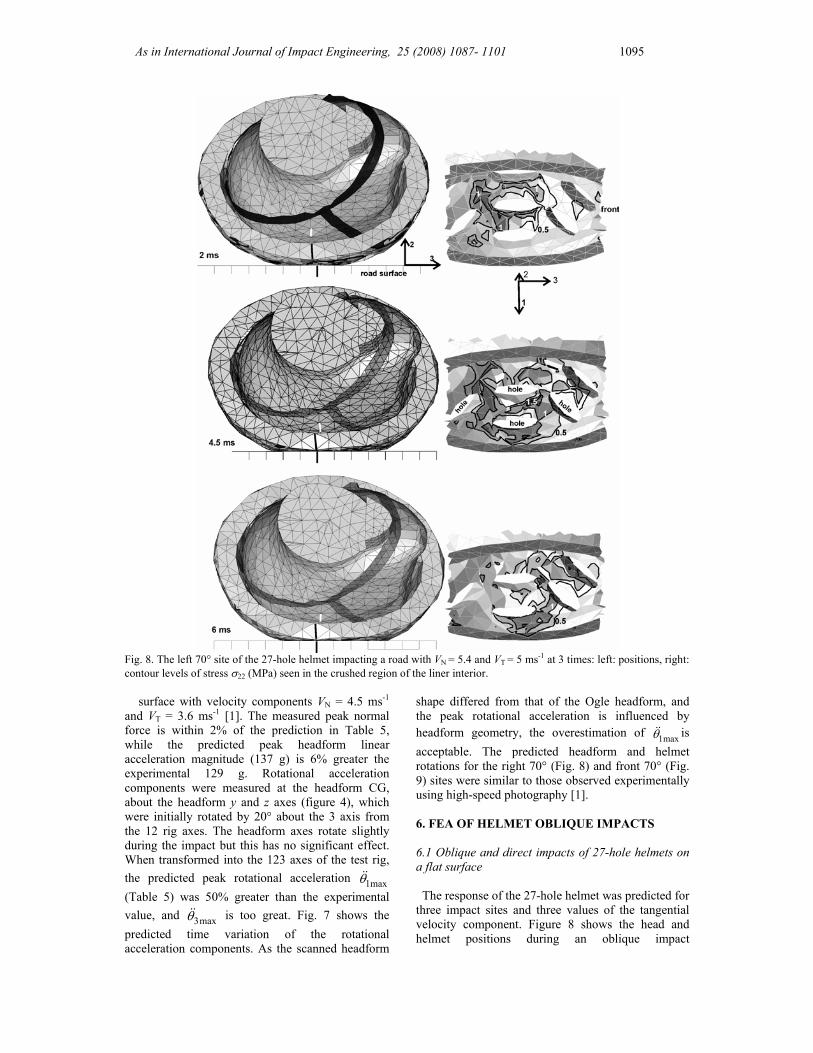
Fig. 8. The left 70° site of the 27-hole helmet impacting a road with VN = 5.4 and VT = 5 ms-1 at 3 times: left: positions, right: contour levels of stress σ22 (MPa) seen in the crushed region of the liner interior.
surface with velocity components VN = 4.5 ms-1 and VT = 3.6 ms-1 [1]. The measured peak normal force is within 2% of the prediction in Table 5, while the predicted peak headform linear acceleration magnitude (137 g) is 6% greater the experimental 129 g. Rotational acceleration components were measured at the headform CG, about the headform y and z axes (figure 4), which were initially rotated by 20° about the 3 axis from the 12 rig axes. The headform axes rotate slightly during the impact but this has no significant effect. When transformed into the 123 axes of the test rig, the predicted peak rotational acceleration max1θ&& (Table 5) was 50% greater than the experimental value, and max3θ&& is too great. Fig. 7 shows the predicted time variation of the rotational acceleration components. As the scanned headform
shape differed from that of the Ogle headform, and the peak rotational acceleration is influenced by headform geometry, the overestimation of max1θ&& is acceptable. The predicted headform and helmet rotations for the right 70° (Fig. 8) and front 70° (Fig. 9) sites were similar to those observed experimentally using high-speed photography [1].
6. FEA OF HELMET OBLIQUE IMPACTS 6.1 Oblique and direct impacts of 27-hole helmets on a flat surface
The response of the 27-hole helmet was predicted for three impact sites and three values of the tangential velocity component. Figure 8 shows the head and helmet positions during an oblique impact
As in International Journal of Impact Engineering, 25 (2008) 1087- 1101 1096
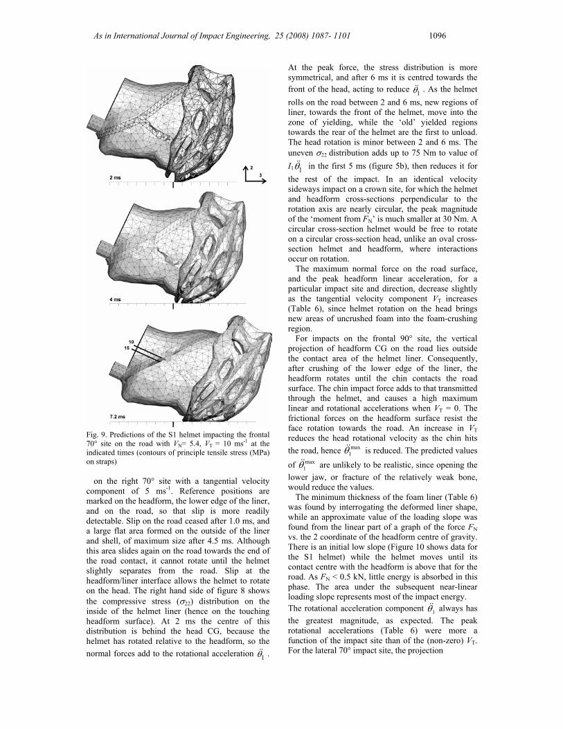
Fig. 9. Predictions of the S1 helmet impacting the frontal 70° site on the road with VN= 5.4, VT = 10 ms-1 at the indicated times (contours of principle tensile stress (MPa) on straps)
on the right 70° site with a tangential velocity
component of 5 ms-1. Reference positions are marked on the headform, the lower edge of the liner, and on the road, so that slip is more readily detectable. Slip on the road ceased after 1.0 ms, and a large flat area formed on the outside of the liner and shell, of maximum size after 4.5 ms. Although this area slides again on the road towards the end of the road contact, it cannot rotate until the helmet slightly separates from the road. Slip at the headform/liner interface allows the helmet to rotate on the head. The right hand side of figure 8 shows the compressive stress (σ22) distribution on the inside of the helmet liner (hence on the touching headform surface). At 2 ms the centre of this distribution is behind the head CG, because the helmet has rotated relative to the headform, so the normal forces add to the rotational acceleration 1θ&& .
At the peak force, the stress distribution is more symmetrical, and after 6 ms it is centred towards the front of the head, acting to reduce 1θ&& . As the helmet rolls on the road between 2 and 6 ms, new regions of liner, towards the front of the helmet, move into the zone of yielding, while the ‘old’ yielded regions towards the rear of the helmet are the first to unload. The head rotation is minor between 2 and 6 ms. The uneven σ22 distribution adds up to 75 Nm to value of I1 1θ&& in the first 5 ms (figure 5b), then reduces it for the rest of the impact. In an identical velocity sideways impact on a crown site, for which the helmet and headform cross-sections perpendicular to the rotation axis are nearly circular, the peak magnitude of the ‘moment from FN’ is much smaller at 30 Nm. A circular cross-section helmet would be free to rotate on a circular cross-section head, unlike an oval cross-section helmet and headform, where interactions occur on rotation.
The maximum normal force on the road surface, and the peak headform linear acceleration, for a particular impact site and direction, decrease slightly as the tangential velocity component VT increases (Table 6), since helmet rotation on the head brings new areas of uncrushed foam into the foam-crushing region.
For impacts on the frontal 90° site, the vertical projection of headform CG on the road lies outside the contact area of the helmet liner. Consequently, after crushing of the lower edge of the liner, the headform rotates until the chin contacts the road surface. The chin impact force adds to that transmitted through the helmet, and causes a high maximum linear and rotational accelerations when VT = 0. The frictional forces on the headform surface resist the face rotation towards the road. An increase in VT reduces the head rotational velocity as the chin hits the road, hence max
1θ&& is reduced. The predicted values
of max1θ&& are unlikely to be realistic, since opening the
lower jaw, or fracture of the relatively weak bone, would reduce the values.
The minimum thickness of the foam liner (Table 6) was found by interrogating the deformed liner shape, while an approximate value of the loading slope was found from the linear part of a graph of the force FN vs. the 2 coordinate of the headform centre of gravity. There is an initial low slope (Figure 10 shows data for the S1 helmet) while the helmet moves until its contact centre with the headform is above that for the road. As FN < 0.5 kN, little energy is absorbed in this phase. The area under the subsequent near-linear loading slope represents most of the impact energy. The rotational acceleration component 1θ&& always has the greatest magnitude, as expected. The peak rotational accelerations (Table 6) were more a function of the impact site than of the (non-zero) VT. For the lateral 70° impact site, the projection

As in International Journal of Impact Engineering, 25 (2008) 1087- 1101 1097
Table 6. Oblique impacts of 27-hole helmet with EPS 83 foam on a road, with VN = 5.4 m s-1 Impact site and direction
VT m s-1
FN max kN
FT max kN
Loading slope N mm-1
min. liner thickness mm
Head amax g
Head max
1θ&& krad s-2
Head max2θ&&
krad s-2
Head max
3θ&& krad s-2
0 9.26 0.72 270 9.5 211# -18 -0.5 -0.7 5 6.61 1.80 270 9.1 162# -8.74 0.7 -1.2
Front 90° down
10 6.15 1.63 270 9.1 149# -7.0 -0.8 -0.7 0 7.67 1.29 510 10.7 179 -5.7 0.7 3.9 5 6.98 1.69 510 8.0 164 -13.7 -0.6 5.1
Right 70° back
10 6.76 1.68 510 9.4 158 -13.0 -0.7 5.5 0 7.55 -0.30 570 17.3 190 ±1.5 1.2 3.5 5 7.32 1.39 570 15.7 180 9.1 2.1 4.0
Crown side
10 6.49 1.47 570 14.4 180 8.6 2.1 4.6 # chin hits road
Fig. 10. Normal force vs. U2 for impacts on S1 helmet at three sites, with VN = 5.4 ms-1, VT = 5 ms-1 (10 ms-1 for the frontal site)
of the headform CG on the road is offset in the 1
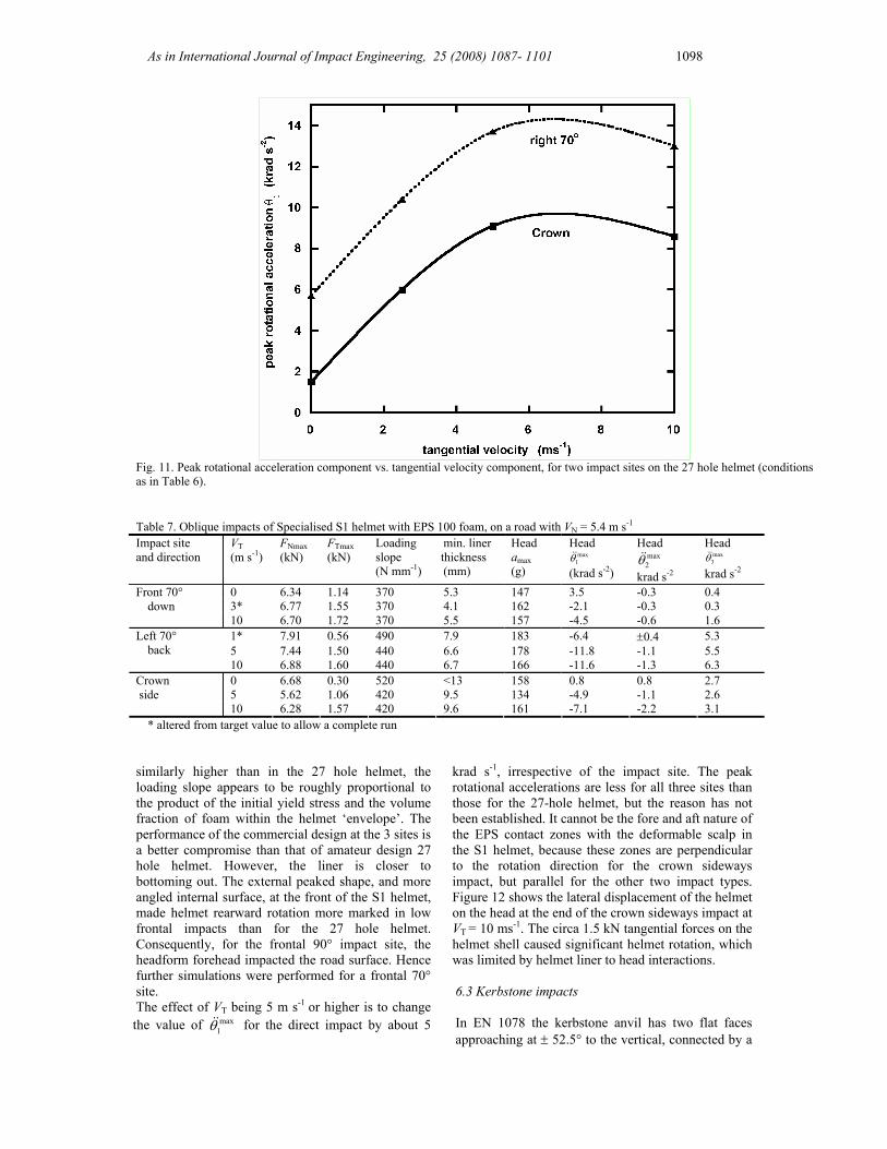
direction from the centre of the foam liner crush area, so rotational acceleration is induced about the 3 axis. The peak 1θ&& values increase with the tangential velocity component VT but become almost constant for VT ≥ 5 ms-1 (Fig. 11), for two impact sites.
6.2 Oblique and direct impacts of the Specialised S1 helmet on a flat surface
Liner element distortion control was necessary, with length ratio = 0.2 to achieve stable FEA for the complete impact. In cases marked * in Table 7, the values of VT were moved away from target values to allow the simulation to reach the peak liner crush. EPS of density 101 kg m-3 was used, as
in the real helmet. Figure 9 shows a sequence of predicted helmet positions on the head, and deformed helmet shapes, in a frontal 70° test with VN = 5.4 and VT = 10 m s-1. The front of the helmet crushed and moved down the forehead.
The loading slopes (Table 7) for the S1 helmet are lower at the crown site than for the 27-hole helmet. As a result, since neither helmet has bottomed out (minimum thickness → zero), the peak headform linear accelerations are less at the crown site than for the 27 hole helmet. A comparison at the left/right 70° site is inconclusive; the S1 helmet has a slightly lower loading slope, but it also has less coverage at the side, while the peak linear accelerations are similar. Given that the foam initial yield stress in the S1 helmet is 18% higher, while the volume fraction of air holes is also
As in International Journal of Impact Engineering, 25 (2008) 1087- 1101 1098
Fig. 11. Peak rotational acceleration component vs. tangential velocity component, for two impact sites on the 27 hole helmet (conditions as in Table 6).
Table 7. Oblique impacts of Specialised S1 helmet with EPS 100 foam, on a road with VN = 5.4 m s-1
Impact site and direction
VT (m s-1)
FNmax (kN)
FTmax (kN)
Loading slope (N mm-1)
min. liner thickness (mm)
Head amax (g)
Head max
1θ&& (krad s-2)
Head max2θ&&
krad s-2
Head max
3θ&& krad s-2
0 6.34 1.14 370 5.3 147 3.5 -0.3 0.4 3* 6.77 1.55 370 4.1 162 -2.1 -0.3 0.3
Front 70° down
10 6.70 1.72 370 5.5 157 -4.5 -0.6 1.6 1* 7.91 0.56 490 7.9 183 -6.4 ±0.4 5.3 5 7.44 1.50 440 6.6 178 -11.8 -1.1 5.5
Left 70° back
10 6.88 1.60 440 6.7 166 -11.6 -1.3 6.3 0 6.68 0.30 520 <13 158 0.8 0.8 2.7 5 5.62 1.06 420 9.5 134 -4.9 -1.1 2.6
Crown side
10 6.28 1.57 420 9.6 161 -7.1 -2.2 3.1 * altered from target value to allow a complete run
similarly higher than in the 27 hole helmet, the loading slope appears to be roughly proportional to the product of the initial yield stress and the volume fraction of foam within the helmet ‘envelope’. The performance of the commercial design at the 3 sites is a better compromise than that of amateur design 27 hole helmet. However, the liner is closer to bottoming out. The external peaked shape, and more angled internal surface, at the front of the S1 helmet, made helmet rearward rotation more marked in low frontal impacts than for the 27 hole helmet. Consequently, for the frontal 90° impact site, the headform forehead impacted the road surface. Hence further simulations were performed for a frontal 70° site. The effect of VT being 5 m s-1 or higher is to change the value of max
1θ&& for the direct impact by about 5
krad s-1, irrespective of the impact site. The peak rotational accelerations are less for all three sites than those for the 27-hole helmet, but the reason has not been established. It cannot be the fore and aft nature of the EPS contact zones with the deformable scalp in the S1 helmet, because these zones are perpendicular to the rotation direction for the crown sideways impact, but parallel for the other two impact types. Figure 12 shows the lateral displacement of the helmet on the head at the end of the crown sideways impact at VT = 10 ms-1. The circa 1.5 kN tangential forces on the helmet shell caused significant helmet rotation, which was limited by helmet liner to head interactions.
6.3 Kerbstone impacts
In EN 1078 the kerbstone anvil has two flat faces approaching at ± 52.5° to the vertical, connected by a

As in International Journal of Impact Engineering, 25 (2008) 1087- 1101 1099
cylindrical surface having a 15 mm radius of curvature. Although the impact velocity of 4.57 ms-1 is lower than for the flat anvil, the test may be more difficult to pass. For oblique impacts, both the
Fig. 12. Lateral tilt of S1 helmet on the headform after 10 ms of a crown sideways impact with VN = 5.4 and VT = 10 ms-1.
kerbstone angular alignment, and offset of its midline from the headform CG can be varied.
Figure 13 shows predicted compressive stress fields on the liner exterior at the peak impact force, for two kerbstone positions. As the kerbstone is large compared with the ventilation holes, there are only minor differences between the predictions (Table 8). Consequently the kerbstone midline alignment, relative to rows of ventilation holes, does not greatly influence the results. The minimum liner thickness in the impact is less than for the road impacts in Table 5, but the impact velocity is higher than that specified in EN 1078. The peak rotational head accelerations are low. In general, the loading slope for kerbstone impacts is about 50% of that for a flat road impact. 7. Discussion
To match the road force data for oblique impact
tests [1], the road/shell friction coefficient must be close to 0.25. Experimentally [15] λR ≅ 0.3 for a bicycle helmet shell impacting a very rough surface, so the slightly lower value for a roughened metal surface is reasonable. It is difficult to deduce exact parameters for the head/helmet interface; the modelling is insensitive to the value of λH when it is less than λR, so a value of λH = 0.2 was used. There is no experimental data for frictional response of the wig material under compressive stresses of several MPa, to confirm the value.
Fig. 13. Impacts of 45° frontal sites on a 27-hole helmet on a kerbstone with VN = 5.4 and VT = 5 ms-1: (a) central site after 6 ms, (b)
site rotated 10° after 6.5 ms. Contours of stress σ22 (MPa) are shown on the liner, when the impact force is highest.
Table 8. 27-hole helmet with EPS 83 foam, impacting a kerbstone with VT = 5 m s-1 and VN = 5.4 m s-1 Impact site and kerbstone orientation
FN max kN
FT max kN
Loading slope N mm-1
min. liner thickness mm
Head amax g
Head max
1θ&& krad s-2
Head max
2θ&& krad s-2
Head max
3θ&& krad s-2
Front 45° (fig 13a) 5.10 1.99 260 7.5 149 3.5 -0.6 0.8 Front 45° r10 (fig 13b) 5.11 1.70 240 6.2 140 3.2 1.0 1.4 Right 70° (along3 axis) 5.06 1.24 210 3.1 125 -7.0 0.4 2.8

As in International Journal of Impact Engineering, 25 (2008) 1087- 1101 1100
The hairs of the acrylic wig may slide over each
other, but it seems unlikely that this occurs at shear stress much less than 500 kPa. Further measurements, of the type described in [1], are needed over a wider range of impact velocities, with different types of road surface, to better establish the individual interface friction conditions. At this early stage in FEA of oblique bicycle helmet impacts, it is preferable to keep the model simple with a minimum number of disposable parameters. The modelling in [14] used a greater number of arbitrary parameters, but this only affected the predictions of head rotational acceleration and not those of head linear acceleration.
In answer to the first question posed in the introduction, the impact force normal to the road is hardly affected by the interface friction coefficients, being determined by the crushing of the EPS liner. The impact force tangential to the road can be well approximated as the product of an effective friction coefficient and the normal force. The effective coefficient falls between the values for the road surface and the head surface, as shown in figure 6.
The second issue was the geometric features that determine the protector rotation. The predicted helmet rotations at the end of the simulations (figures 8c and 9c) are similar to those in photographs after oblique impact tests [1]. They are limited by geometrical interactions of the relatively hard helmet liner and skull, so long as the retention strap system limits the helmet lifting from the head. Forward helmet rotation is eventually limited by its brim contacting the nose, while rotation about a neck to nape axis is limited by the oval shape of the head. However, as the liner interior is somewhat larger than the headform, some rotation will occur. In protective products mounted on deep soft tissue, similar rotation limits do not occur. Hence, the geometric features that affect protector rotation are specific to the body area protected. One headform rotational acceleration was overestimated by 50%, probably because the model headform shape differed from that used in the experiments. The peak rotational acceleration was mainly caused by the tangential force FT on the helmet shell surface, with a significant contribution from the normal forces if the helmet/head section perpendicular to the axis of rotation is oval. Headform rotational accelerations are significant even in normal (vertical) impacts, and are probably a function of head shape, which varies considerably in the human population.
The presence of ventilation holes in helmets do not change the basic design method for headform linear acceleration (nor does the oblique nature of the impact), as the area of crushed foam includes several holes. Consequently, the relationship between normal force and liner compressive deflection is still linear during loading. For a road impact with 75 J energy, as in EN 1078, the loading slope must be > 300 N mm-1, as the 25 mm maximum deflection would be close to causing the liner to bottom out. It also needs to be <
660 N mm-1 as the peak normal force would be 10 kN at 15 mm deflection, causing a 200 g peak linear acceleration close to the limit. Both measured loading slopes [1] and those predicted by FEA fall between these limits. Allowance for kerbstone impacts with 50 J energy suggests that relatively high loading slopes should be used for road impacts. The predicted loading slope (440 N mm-1) for the right 70° site on the S1 helmet in Table 6 is similar to measured value of 490 N mm-1 [1]. The foam density must be increased to compensate for the reduction in the head surface area covered by foam. The 27-hole helmet, with a 25% area fraction of ventilation holes, requires an EPS foam density of about 83 kg m-3 to pass the direct impact tests of EN 1078. The S1 helmet shape, with a larger volume fraction of holes, uses EPS of density 101 kg m-3. The location and size of some holes may be determined more by impact test requirements, than by their effectiveness in ventilating the head [15]; large holes at the front of helmets create air flow past the forehead, while holes at the top and sides of helmets may have little effect. If holes are omitted from the helmet sides, the local loading stiffness increases, so an impact test might be failed.
FEA allows what if simulations to be performed, prior to the expense of liner and shell mould tooling. The effects of thicker liners and changes to the coverage of the head are considered elsewhere [14]. The analysis here (Table 4) shows that small reductions in the friction coefficient λR at the shell/road interface, if λR > λH , may produce little benefit in reducing the peak head rotational acceleration, but large reductions could be beneficial.
8. Conclusions
Dynamic FEA predictions, of the peak linear and
rotational headform accelerations in bicycle helmet oblique impact tests, were validated by comparison with experimental impacts. Consequently, the interface friction coefficients could be evaluated. The design method for the peak headform linear acceleration was confirmed. The loading slope appears to be proportional both to the foam initial yield stress and the volume fraction of foam inside the helmet envelope, in the impact region.
The predicted peak headform rotational accelerations depended on the impact site and direction, and became nearly constant for a tangential velocity component > 5 ms-1. The values, ranging up to 12 krad s-2 for a simulated commercial helmet, were strongly influenced by the low coefficient of friction of the helmet on the head, with the higher friction coefficient of the helmet on the road being less important. Rotational head acceleration was also caused by the centre of the pressure distribution on the head not passing through its centre of gravity, a factor that also operated in direct impact tests.

As in International Journal of Impact Engineering, 25 (2008) 1087- 1101 1101
Acknowledgments
The authors thank EPSRC for support under grant
R89790, and Dr P. Brühwiler of EMPA, St Gallen, Switzerland for providing scanned headform and helmet data. One referee is thanked for suggesting the use of constant friction coefficients, rather than shear stress limits, at the interfaces
References [1] Gilchrist A & Mills NJ, Oblique impact testing of
bicycle helmets, Int. J. Impact Engng. 2008; 35: 1075-1086.
[2] Gilchrist A, Mills NJ & Khan T, Survey of head, helmet and headform sizes related to motorcycle helmet design, Ergonomics 1988; 31:1395-1412.
[3] Mills NJ & Ward R, The biomechanics of motorcycle helmet retention, IRCOBI (International Research Committee on Biokinetics of Impacts) conference, Goteborg 1985: 117-27.
[4] Mills NJ & Gilchrist A, The effectiveness of foams in bicycle and motorcycle helmets. Accid. Anal. Prev. 1991; 23: 153-163.
[5] Brühwiler PA, Dumas C et al., Bicycle helmet ventilation and comfort angle dependence, Euro. J. Appl. Physio. 2004; 92: 698-701.
[6] BSEN 1078 Helmets for pedal cyclists and for users of skateboards and roller skates, British Standards Institution, London.
[7] van der Bosch E, Leensen MWBM et al., Development of an improved dummy head for use in helmet certification tests, Proc. ASME Symp. On Crashworthiness, (2000) Orlando.
[8] Masso-Moreu Y & Mills NJ, Impact compression of polystyrene foam pyramids, Int. J. Impact Engng. 2003; 28: 653-676.
[9] Masso-Moreu Y & Mills NJ, Rapid hydrostatic testing of rigid polymer foams, Polymer Testing 2004; 23: 313-322.
[10] Moosa A & Mills NJ, Analysis of bend tests on polymer foams, Polymer Testing 1998; 17: 357-378.
[11] Author’s unpublished data. [12] Doroudiani S & Kortshot MT, Polystyrene foams III.
Structure-tensile property relationships, J. Appl. Polym. Sci. 2003; 90: 1427-34.
[13] Govaert IE & Tervoort TA, Strain hardening of polycarbonate in the glassy state. J. Polym. Sci. B. Polymer Physics 2004; 42: 2041-9.
[14] Mills NJ & Gilchrist A, Bicycle helmet design, Proc. I. Mech. E., Part L, J. Materials Design and Applications 2006; 220: 167-180.
[15] Brühwiler PA, Buyan M. et al., Heat transfer variations of bicycle helmets, J. Sports Sci. 2006: 24, 999-1011.