Embed Size (px)
Citation preview

FEASIBILITY OF AND OPTIONS
FOR A PUBLIC BIOENERGY HEATING SYSTEMS RETROFIT
FOR
ENERGY SOLUTIONS CENTRE
GOVERNMENT OF YUKON
March 31, 2009

Energy Solutions Centre March 31, 2009 Government of Yukon Feasibility Study _________________________________________________________________________________________________________________________
Page 2 of 72
INDEX
1.0. PREFACE page 4
2.0. EXECUTIVE SUMMARY page 5
3.0 DEFINITIONS page 7
4.0. BIOMASS HEATING SYSTEMS page 9
4.1. BIOMASS FUELED HEATING EQUIPMENT SELECTION CRITERIA page 9 4.2. BIOMASS BOILER SIZING AND SYSTEM DESIGN page 13 4.3. BIOMASS BOILER AND COMPONENTS page 15 4.4. SYSTEM CONTROLS page 20 4.5. BACKUP BOILER AND SYSTEM CONTROLS page 21 4.6. BOILER HOUSE page 22 4.7. FUEL STORAGE page 24
5.0. BIOMASS FUELS page 25
5.1. WOOD FUELS GENERAL page 25
5.2. PELLETS page 26 5.3. CHIPS page 31
5.4. PELLETS VS. CHIPS page 34 5.5. LIST OF FUEL SUPPLIERS page 40
6.0. SYSTEM OPERATIONS AND MAINTENANCE page 42
6.1. BOILER page 42
6.2. STORAGE SYSTEM page 42
6.3. FEED SYSTEM page 42
6.4. FIRE SAFETY page 42
6.5. ASH HANDLING page 42
6.6. MAINTENANCE PERSONNEL page 43
Energy Solutions Centre March 31, 2009 Government of Yukon Feasibility Study _________________________________________________________________________________________________________________________
Page 3 of 72
7.0. SOCIO – ECONOMICS OF IMPLEMENTING A YUKON BASED
BIOMASS HEATING STRATEGY page 44 7.1. ECONOMICS page 44
7.2. SOCIAL page 54
8.0. THREE PUBLIC BUILDINGS page 57
8.1. ELIJAH SMITH SCHOOL page 57 8.2. HIDDEN VALLEY SCHOOL page 58 8.3. PROPERTY MANAGEMENT FACILITIES BUILDING page 59
9.0. CONCLUSIONS page 60
10.0. LIST OF REFERENCES/LINKS page 61 11.0. DISCLAIMER page 62 12.0. APPENDIX page 63
Energy Solutions Centre March 31, 2009 Government of Yukon Feasibility Study _________________________________________________________________________________________________________________________
Page 4 of 72
904 Glenora Ave., North Vancouver, B.C., Canada V7R 1M3 Tel: 604-984-4057 Fax: 604-984-4087
North Vancouver March 31, 2009 1.0 PREFACE The objective of this study was to undertake an assessment of the economic and environmental feasibility of converting three public buildings, owned and operated by the Yukon Government, from their existing hydrocarbon-based heating systems to new low-pressure biomass-fuelled space heating systems. The study also includes the conceptual design for, and economic feasibility of systems that are suitable for use in the Yukon’s unique northern setting.
The report is intended to provide information required for decisions about how the government could implement a cost-effective, replicable pilot project that would establish an effective model for future conversions of government building heating systems in Yukon. The study was conducted between December 2008 and March 2009 by Rod Graham and Markku Riionheimo of Ventek Energy Systems Inc. Financial analysis was provided by David Hudson CA. Local assistance was provided by Shane Andre of the Energy Solutions Centre. We trust that this report fully meets your present requirements in seeking information to establish Yukon based bioenergy policies, undertake bioenergy retrofits and to help in deciding the direction and magnitude of bioenergy use in Yukon in the coming years. Sincerely,
VENTEK ENERGY SYSTEMS INC.
Markku Riionheimo
Energy Solutions Centre March 31, 2009 Government of Yukon Feasibility Study _________________________________________________________________________________________________________________________
Page 5 of 72
2.0 EXECUTIVE SUMMARY 2.0.1. SUMMARY
This report was prepared for the Yukon Government’s Energy Solutions Centre and Property Management Division. The emphasis of the report is to assess the economic and environmental feasibility of converting three public buildings, owned and operated by the Yukon Government, from fossil fueled heating systems to biofuel based equipment. Specific and unique requirements for selection, sizing, controls, and fuel storage for a biomass boiler heating system are discussed. Typical biomass boiler operations, installations and maintenance requirements are detailed. Since the European manufacturers use more advanced combustion technology and have significantly more experience in producing high end mid-range boiler systems, the products from the European boiler manufacturers are selected for evaluation purposes. Wood based biofuels and the effects of moisture content and fuel quality on net energy values are analyzed. Examples of current European fuel standards are presented for both wood chips and wood pellets. The socio-economic implications of bioenergy conversions are outlined, including evaluation of flue gas emissions. Historical energy cost comparisons are made and future energy prices are projected for comparison. The focus of this report is to give guidance and recommendations for Yukon to create a bioenergy industry that takes into account all aspects of supply including both fuel and equipment selection. The recommendations in this report are made to both identify and leverage the unique opportunity Yukon has to create a viable and sustainable bioenergy industry. 2.0.2. CONCLUSIONS AND RECOMMENDATIONS Biomass boiler systems are subject to unique design criteria. The capital costs of these systems are often relatively high and design and installation of these systems requires more attention to sizing and other selection details. The weighting of the size versus total load, turn down ratio, and peak load need all be taken into consideration. Yukon possesses unique and often difficult obstacles during the long heating season. The use of replicated biomass boiler systems will reduce maintenance costs and increase operational security with locally trained personnel. Replication of boilers, controls, fuel storage, conveying systems and fuel source will help to reduce costs and ensure reliable systems. Special consideration for insulated boiler houses and the use of backup generators should be addressed. The standardization of all aspects of the biomass boiler systems should be considered throughout the Yukon in order to ensure a successful Bio Energy Industry. The selection of a reputable, established bioenergy equipment supplier with a proven track record, Canadian distribution network for parts, service, and training should be given top priority. The controls interface with existing facilities is important in selection and design. Remote monitoring of systems should be mandatory on all installations.

Energy Solutions Centre March 31, 2009 Government of Yukon Feasibility Study _________________________________________________________________________________________________________________________
Page 6 of 72
High quality biomass boilers should produce flue gas emission levels as low as 30 mg/Nm3 and with the addition of flue gas screens down to 20 mg/Nm3.
Wood based biofuels require stringent standardization for proper combustion and low flue gas emissions. A rigid fuel standard must be implemented for biofuels for Yukon. This will ensure that the end user experiences the least number of operational difficulties and receives full energy value for the fuel. Testing of fuels needs to be done on an on-going basis with a dispute mechanism in place to settle any discrepancies in fuel deliveries. Boilers from most reputable biomass boiler manufacturers are capable of burning both wood chips and wood pellets. However, it must be recognized that standardization of the fuel will result in the most cost-effective and reliable operation. The production of wood chips requires adherence to strict criteria with respect to size (length and width), moisture content, and percentage of bark and fines. Monitoring of these performance criteria is mandatory for all aspects of each application. Pellets on the other hand, because of their inherently standardized properties produced during manufacture are easier to standardize and monitor. A number of European fuel standards exist and it is recommended that Yukon adopt the new EU biofuel standard CEN 14962 when it is introduced later this year. Although the cost of producing wood chips may initially appear to be lower, the bulk density differences between wood chips and wood pellets are significant. Wood chips require significantly greater transportation logistics, storage foot print, size and design; conveying system, and equipment design costs. Purchasers of wood bioenergy fuels need to pay for net energy - and as such all calculations should be based on standardized formulas that are based on net calorific value at constant pressure, including moisture, at received bases. When looking at the long term potential of future bioenergy conversions; not only in the domestic and institutional sector, but also in the industrial sector; along with the properties of chips versus pellets, it is recommended that Yukon adopt a long term strategy to utilize and design bioenergy systems for use with wood pellets. Fossil fuel and pellet prices are analyzed and are projected into the future for use in the life cycle cost analysis. Elijah Smith School has the most potential as a pilot project for a biomass boiler system. Existing infrastructure lends itself to a very compatible installation. The Hidden Valley school, though more capital intensive, would be a good second choice. The conversion of the existing gymnasium make-up air unit to a water heating coil, would add to the capital cost of this project. The public works building would require substantial re-piping and because of the contemplated expansion should be considered the third option.
Energy Solutions Centre March 31, 2009 Government of Yukon Feasibility Study _________________________________________________________________________________________________________________________
Page 7 of 72
3.0. DEFINITIONS
APC Air Pollution Collection Equipment, term of reference including equipment such as cyclones, electrostatic precipitators, etc. ASHRAE American Society of Heating, Refrigeration and Air-Conditioning Engineers Inc. Industry standards for heating, refrigeration and air-conditioning systems. ASME American Society of Mechanical Engineers, administrator of the International Boiler and Pressure Vessel Code among other regulations. B.D.T. Bone Dry Ton – Traditional unit of measure used by industries (pulp/paper, biomass power) that utilize biomass as a primary raw material. One bone dry ton (BDT) is 2,000 pounds of biomass (usually in chip form) at zero percent moisture. Typically biomass collected and processed in the forest is delivered “green” to the end use facility at 50% moisture. One BDT at 50% moisture content is two green tons (4,000 pounds at 50% moisture content). Biofuel/Biomass Fuel derived from organic matter in trees, agricultural crops and other living plant material = renewable energy. Carbohydrates are the organic compounds that make up biomass. These compounds are formed in growing plant life through photosynthesis, a natural process by which energy from the sun converts carbon dioxide and water into carbohydrates, including sugars, starches and cellulose. For the purpose of this report, biofuel/biomass will refer to wood pellets and wood chips. BMB Biomass Boiler
Carbon Neutral or having a zero carbon footprint, refers to achieving net zero carbon emissions by balancing a measured amount of carbon released during combustion with an equivalent amount of carbon sequestered. Biofuels are classified to be carbon neutral because the amount of CO2 released during the combustion equals the CO2 the tree absorbs from the atmosphere during its life. CEN European Committee for Standardization, (Comité Européen de Normalisation). A business facilitator in Europe, removing trade barriers for European industry and consumers. Its mission is to foster European economy in global trading, the welfare of European citizens and government. Through its services it provides a platform for the development of European Standardization and other technical specifications. Cogeneration The combined generation of both heat and power at one facility using the same fuel source. Typically the heat is used to generate steam that is utilized on site (process steam). Power generated is in the form of electricity that is utilized on site or sold to a local utility. The heat can also be distributed into a district heating system, used for drying the fuel, or discharged to the atmosphere. Typically the facility will produce 35 % electricity 55 % heat with 10 % allowed for losses.
Energy Solutions Centre March 31, 2009 Government of Yukon Feasibility Study _________________________________________________________________________________________________________________________
Page 8 of 72
CSA Canadian Standard Association, not-for-profit membership-based association serving business, industry and government Higher Heating Value Also called gross heating value. The total heat obtained from combustion of a specified amount of fuel and its stoichiometrically correct amount of air, both being at 60°F when combustion starts, and the combustion products being cooled to 60°F before the heat release is measured. Lower Heating Value Also called net heating value. The gross heating value minus the latent heat of vaporization of the water content of the fuel and water formed by the combustion of the hydrogen in the fuel. Hog Fuel A crushed mixture of biofuel normally consisting of bark, wood fibre, chips etc.
PM Particulate matter PM10 Airborne particles that are 10 microns (0.010 mm) or less in size PM2.5 Airborne particles that are 2.5 microns (0.002,5 mm) or less in size PM10-2.5 Airborne particles in the size range of 2.5 to 10 microns in size, known as Coarse Fraction of PM10 Tonne Metric ton = 1,000 kg ~ 2200 lbs

Energy Solutions Centre March 31, 2009 Government of Yukon Feasibility Study _________________________________________________________________________________________________________________________
Page 9 of 72
4.0. BIOMASS HEATING SYSTEMS 4.1 BIOMASS FUELED HEATING EQUIPMENT SELECTION CRITERIA
4.1.1. Replicability The ability to replicate boiler system design in several different applications is important when dealing with sparsely populated areas such as Yukon. This will create a quick learning curve for the maintenance personnel without the need of having to deal with many different manufacturers with many different problems. All aspects of the system should be replicated including not only the boiler but the feed systems, controls, pumps, ash removal system and control sensors. By replicating a designed system the biofuel can also be standardized. Inventory of the spare parts becomes less expensive and complicated.
4.1.2. Remote Applications When dealing with boiler systems in remote communities, a manufacturer with a proven track record, low maintenance system, minimum number of models containing interchangeable parts, and a good service network must be given a high priority in the selection process.
4.1.3. Public Safety Branch Requirements The Public Safety Branch sets rules for safe installation, operation and inspection of boiler systems. These rules must be strictly adhered to for a continued safe operation of the systems.
4.1.4. ASME Certification An ASME certification of a boiler is normally a pre-requisite requirement for anyone to operate a boiler system as a closed system in North America. While some boilers that do not bear ASME certification have been installed to run as open systems, it is not reasonable to assume that it could be done in the buildings covered by this study.
4.1.5 CSA Approval All electrical devices included in the boiler system must bear the label of CSA. BMB boiler systems that carry a blanket CSA approval for the entire operating system should be given high priority.
4.1.6. Range of Sizes and models Some manufacturers have only one model which restricts the size range of applications while others have a multitude of models to cover a wide range of applications. A good balance is important to make it easier to store spare parts and have maintenance know-how when dealing with repairs in remote communities. The higher number of different models the more expensive it is to maintain them. In some of the largest installations it is often better to have two biomass boilers of the same size to cover the extreme lows of the system operation. This enables one BMB to have longer run times and enables the design to match the lower heat demand with the single boiler turn down ratio. 4.1.7. Control system and remote monitoring capabilities Having a remote monitoring and control option is a must when dealing with a multitude of boiler operations in areas where distances are vast and where trained trades people are not readily available to attend malfunctioning equipment on site. The boiler control system should be able to interface with the existing control system when doing retrofits.
Energy Solutions Centre March 31, 2009 Government of Yukon Feasibility Study _________________________________________________________________________________________________________________________
Page 10 of 72
4.1.8. Reliability of parts supply Certain parts must be readily available in case of emergencies. A manufacturer who has a sales and service network in Canada has a definite advantage when assuring a trouble free boiler system operation. A list of recommended spare parts for each model should be included with each system.
4.1.9. Training availability Training facilities to train personnel responsible in maintaining biomass boiler systems is a requirement for any reputable boiler manufacturer. Today’s high-tech boiler systems can-not be operated without properly trained personnel.
4.1.10. Yukon Requirements
Boiler Inspection Branch
Contact: Daniel Price Chief Mechanical Inspector
A Canadian Registration Number (CRN) is required for all pressure vessels over 15 psi entering Canada. The CRN is a number issued by each province or territory of Canada. The CRN identifies that the design of a boiler, pressure vessel, or fitting has been accepted and registered for use in that province or territory. In addition to the CRN number all boilers must meet and be approved to the CSA Standard B51, “Boiler, Pressure Vessel and Pressure Piping Code.” The CSA B51 standard provides a more inclusive definition of a pressure vessel.
A Canadian Registration Number (CRN) for a boiler or pressure vessel is defined by CSA B51 Clause 4.3 as:
• consisting of a letter, four digits, and a decimal point followed by up to ten digits and/or two letters
• the first letter and four digits are part of a sequential numbering system used by the issuing province or territory
• the first digit or letter to the right of the decimal point indicates the province that issued the particular number
• the following identifications are used in accordance with the code: 1 - British Columbia 2 - Alberta 3 - Saskatchewan 4 - Manitoba 5 - Ontario 6 - Quebec 7 - New Brunswick 8 - Nova Scotia 0 (zero) - Newfoundland T - Northwest Territories Y - Yukon Territory N - Nunavut
Energy Solutions Centre March 31, 2009 Government of Yukon Feasibility Study _________________________________________________________________________________________________________________________
Page 11 of 72
• the letter C may follow the designation of first registration if a design is registered in all jurisdictions. No jurisdiction issues the letter C; it is a convenience for stamping once the manufacturer has received all the registrations.
• to be eligible for use in Alberta, the CRN must have the digit 2 somewhere after the decimal point.
Also from B51-97 4.12
“Manufacturers in countries other than Canada and the USA who do not have the appropriate ASME Certificate of Authorization shall, when submitting designs of boilers and pressure vessels for registration, submit evidence acceptable to the regulatory authority that the quality control system for the manufacturing facilities and procedure is equivalent to that of the applicable ASME Code."
The various codes and regulations for boiler certification differ across Canada and are subject to varying interpretation. ACI Central Inc. a nonprofit organization located on Prince Edward Island was contacted for clarification of this subject. ACI’s voluntary membership is limited to the Chief Inspectors of Canada’s Provinces and Territories. It was founded on the principals of uniformity through the promotion of standardization procedures for design, registration and issuing of Canadian Registration Numbers (CRN Numbers). Through ACI a company can register a boiler design and obtain a CRN number in Prince Edward Island, Nova Scotia, New Brunswick, Newfoundland, Yukon, Northwest Territories, and Nunavut. The criteria required by ACI to issue a CRN number are: • ASME approval of the pressure vessel • Compliance to CSA B51 • Prior registry with the National Board of Boiler and Pressure Vessel Inspectors The CSA B51 is a Canadian Code that facilitates interprovincial trade of pressure vessels, pipe and fittings. The code sets out details of design, registration criteria, and quality control issues. There are no formulas or calculations offered in the text but simply acts as a guide for design criteria. CSA B51 references all of the ASME sections for compliance to design and registration. Each Chief Boiler Inspector for all Provinces and Territories have the ability, under their individual legislation, to approve a non ASME approved pressure vessel or fitting. This approval is subject to a lengthy review process and is used for site specific approvals. These approvals are normally on a one time basis.
Building Inspections
Contact: Nick Marnick, Building Inspections Branch
Proper foundations are required for the silo bases. Engineered drawings for site specific applications are necessary. Due to the changes in ground and soils types each application should be investigated for appropriate size and depth of footings. Fire Marshal Contact: Marty Dobbin,Yukon Fire Marshall Yukon requirements are handled through Marty Dobbin of the Yukon Fire Marshals Office. An information package outlining a typical BMB and feed system were forwarded to him for his
Energy Solutions Centre March 31, 2009 Government of Yukon Feasibility Study _________________________________________________________________________________________________________________________
Page 12 of 72
review. Since the normal set back from the silo to the building is 5 meters, there will be no requirements from their department. Section 32.2 of Division B, Limiting Distances, of the national building code was sited for reference purposes.
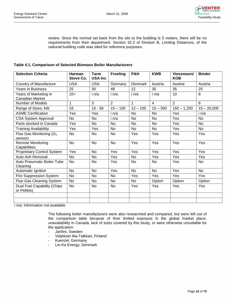
Table 4.1, Comparison of Selected Biomass Boiler Manufacturers
Selection Criteria Harman Stove Co.
Tarm USA Inc
Froeling P&H KWB Viessmann/ KOB
Binder
Country of Manufacture USA USA Germany Denmark Austria Austria Austria Years in Business 25 30 48 12 35 35 25 Years of Marketing in Canadian Market
10+ i n/a i n/a i n/a i n/a 10 8
Number of Models 1 3 2 1 4 2 6 Range of Sizes, kW 33 15 - 58 15 – 100 12 – 100 10 – 300 150 – 1,250 15 – 20,000 ASME Certification Yes Yes i n/a No No Yes i n/a CSA System Approval No No i n/a No No Yes No Parts stocked in Canada Yes No No No No Yes No Training Availability Yes Yes No No No Yes No Flue Gas Monitoring (O2 sensor)
No No No Yes Yes Yes Yes
Remote Monitoring Capabilities
No No No Yes Yes Yes Yes
Proprietary Control System Yes No Yes Yes Yes Yes Yes Auto Ash Removal No No Yes No Yes Yes Yes Auto Pneumatic Boiler Tube Cleaning
No No Yes No No Yes No
Automatic Ignition No No Yes No No Yes No Fire Suppression System No No No Yes Yes Yes Yes Flue Gas Cleaning System No No No No Option Option Option Dual Fuel Capability (Chips or Pellets)
No No No Yes Yes Yes Yes
i n/a: Information not available
The following boiler manufacturers were also researched and compared, but were left out of the comparison table because of their limited exposure in the global market place, unavailability in Canada, lack of sizes covered by this study, or were otherwise unsuitable for the application: - Janfire, Sweden - Veljekset Ala-Talkkari, Finland - Kuenzel, Germany - Lin-Ka Energy, Denmark
Energy Solutions Centre March 31, 2009 Government of Yukon Feasibility Study _________________________________________________________________________________________________________________________
Page 13 of 72
4.2. BIOMASS BOILER SIZING AND SYSTEM DESIGN 4.2.1. Boiler Sizing and Selection To take advantage of the lower price and more environmentally friendly green energy, and to assure continuance and development of Yukon based biofuel industry, the BMB systems should be designed to be the principal supplier of heat in all applications and should be designed to cover 100% of the heating load and the maximum heating period possible. BMB system sizing is very dependent on individual applications. Variables such as domestic hot water usage, ventilation requirements and loads, occupancy, etc. all play an important role in BMB selection. Due to the relatively high cost of the BMB systems, boiler sizing should be studied carefully to provide the target heating capacity without oversizing the system. To provide added safety, a propane or oil fired backup boiler system should also be installed. The backup system should be used to cover the extreme peak loads and to provide the extra heating capacity required to satisfy the engineering safety factor requirements. The backup system should be sized for 50% of the calculated heating load. Since the backup boiler run times will be minimal, there is no requirement for installation of high efficiency condensing boilers. Less expensive sectional cast iron or fin tube boilers are adequate for this intended purpose. The decision to use oil or propane as the backup fuel source will be dependent on the individual application. Retrofit installations should maintain the existing system and fuel source for back up. For new installations, propane systems should be considered for back up as the capital cost and cost of maintenance is normally lower. In summary, to obtain the maximum benefits the economic versus extreme peak design requirements will have to be taken in to account when sizing the BMB system. 4.2.2. Turn-down Ratio The accepted industry standard for a BMB turn-down ratio is 1:5 meaning that the boiler can operate from 100% down to 20% of its rated output before shutting down. It should be noted, that the closer to the maximum rated output the boiler runs, the higher the system efficiency gets. A steady load will also put less strain on the boiler than a constantly changing load. 4.2.3. Backup Generators To assure continued service, a backup generator should be installed as standard equipment to provide backup power during extended power outages. The relatively modest electrical power requirements of the BMB requires only small generators. 4.2.4. Integration of Existing Systems and Replicability When a BMB is installed to service an existing building, the new system should be designed to handle 100% of the heating load and the existing heating system should be left intact and used as a backup. The piping connections would be made in such a manner that the BMB will act as the primary heat source and the existing boilers would start up as a backup to maintain the system set point. The BMB control system would be integrated with the existing control system to ensure the entire system is compatible with all aspects of the building automation system. When using a boiler manufacturer that has the minimum number of models that cover the maximum size of applications, the replicability of the boiler system is increased. By using the same layout, size and/or model of the boiler, and control logic, maintenance and operation of a multitude of boilers is simplified and made easier to administer. The replicability, reliability, and remote visualization and maintenance option of the boiler system should be given top
Energy Solutions Centre March 31, 2009 Government of Yukon Feasibility Study _________________________________________________________________________________________________________________________
Page 14 of 72
priority in Yukon, where the operators and service personnel can-not be present on a continuous bases. 4.2.5. Open Versus Closed Loop Boiler Systems There are two types of boiler systems that can be installed, a closed loop system and an open system. In a closed loop system the boiler and all piping are under pressure and the boiler fluid is not exposed to the atmosphere. The system pressure is normally below 30 psig and is usually set at a few psi higher than what is required to push the fluid through the piping system. In an open system the boiler fluid is open to the atmosphere through a vertical open ended pipe that extends up to a high point of the building and the system is not under significant pressure. The closed system has several advantages: • No need to keep adding water to replace amount lost to evaporation • No oxygen in the water eliminates problems with rust in the water jacket. • No problems with mineral build-up clogging pipes. • Can be hooked directly into other hot water heating systems without the use of heat
exchangers. • Keeping air out of the system adds to pump and boiler life. • Can be used with cross-linked polybutylene pipe (pex) with in floor heating systems. Pex
pipe manufactures do not recommend using an open system because of problems with water chemistry.
• Water exposed to air is what causes many problems in a heating system; circulation, corrosion, heat transfer, chemical maintenance, bacteria build-up, etc.
• Safety. Closed systems are protected by redundant ASME approved relief systems Open systems are often chosen to avoid boiler certification issues such as CRN numbers, ASME certification and CSA approvals. Open systems are still fairly common in smaller residential applications but practically all new commercial and industrial systems designed in Canada today are closed systems. Due to the obvious freeze issues with the vertical pipe, safety, liabilities, increased maintenance costs and potential premature boiler failure, it is recommended that installations in Yukon be closed loop systems.
4.2.6. Special Yukon Design Considerations Apart from the above mentioned design principles, the fact that Yukon winters can be extremely cold must be taken into account when designing a heating system. As explained above, an oversized system may not be able to adjust to fluctuating demand unless it has built-in flexibility such as double units. It is a customary practice in the field of engineering to apply safety factors to all designs, but the overdesign and applying of the safety factors must be done for a reason. Caution must be exercised in designing an over-sized (and over-priced) system that can only handle part of the heating load at the top end of the range. This is especially true for a BMB system If the boiler is located outside the main building in a separate boiler house (see 4.6 Boiler House), the design must take into account the protection of piping to prevent any chance of freezing by either using glycol solution or by heat tracing. In either case appropriate and proper insulating practices must be adhered to. Since glycol reduces the heat transfer efficiency of the boiler, some installations may require the boiler loop to be free of glycol and a water to glycol heat exchanger to be installed with
Energy Solutions Centre March 31, 2009 Government of Yukon Feasibility Study _________________________________________________________________________________________________________________________
Page 15 of 72
the glycol side servicing the areas that are prone to freezing. If the entire system needs to be protected with glycol, then special attention should be paid when selecting the boiler size due to the lower specific heat of the glycol solution. The industry standard for antifreeze applications today is to use propylene glycol which is less toxic than ethylene glycol. Although propylene glycol is approved for use in human food by Food and Drug Administration (FDA), all spills from pressure relief valves, drain valves etc. should be contained and returned to the system.
4.3. BIOMASS BOILER AND COMPONENTS
4.3.1. General The biomass boiler system has a number of components required for safe and efficient operation of the system that are very different from a conventional propane or oil boiler systems. The main components will be discussed separately in the sections below. In general the BMB is a low pressure boiler for operation in a closed loop system and is equipped with the standard operating controls such as low water cut off, flow switch, and a pressure relief valve. BMB are approved for operations in 30 PSIG and 60 PSIG class pending on application. Commonly commercial/light industrial boiler systems in Canada are designed to operate at a working pressure close to15 PSIG. The BMB consists of a fuel intake module equipped with fire safety controls. The fuel is transferred by an above floor screw auger into the firebox and on to the cast iron moving grates. The fuel is automatically ignited by an ignition blower, with the ash being deposited off the end of the grate and dropping into the ash collection trough. With the addition of the ash extraction system the ash is then carried out to the collection bin. The main combustion chamber is lined with refractory. Primary air is introduced under the grate system while secondary air enters from the front of the boiler into the main combustion chamber. The secondary air is introduced in a rotary fashion ensuring complete mixing of the flue gases. The flue gases then pass through the boiler tubing and heat exchanger. The entire system works under negative pressure provided by the induced draft fan (ID Fan). A portion of the flue gas is re-circulated into the primary air circuit for combustion temperature control. All the fans are equipped with variable frequency drives (VFD) and are controlled automatically by the control system for maximum efficiency and burn rate.

Energy Solutions Centre March 31, 2009 Government of Yukon Feasibility Study _________________________________________________________________________________________________________________________
Page 16 of 72
Figure 4.3.1. Cut-away view of BMB
A) Metering bin with slide gate and fire suppression B) Primary air intake to primary air blower C) Automatic ignition D) Automatic ash removal E) Secondary air turbulator F) ID fan G) Flue to stack H) Flue gas recirculation J) Safety heat exchanger
4.3.2 Fuel Feed System A number of different fuel conveyor systems are possible depending on the type of fuel storage system and fuel type. Bunker storage systems for pellets are normally designed with sloped sides that empty into an inclined screw auger while bunkers for chips can use a moving floor system or hydraulic push arms, both of which in turn feed a fuel screw auger. Fuel conveyor systems are designed specifically for each project as the variables can be extensive. For the purpose of this report and the proposed Yukon projects, the above ground feed auger will be described in detail because of its advantages in low cost, reliability and ease of maintenance.

Energy Solutions Centre March 31, 2009 Government of Yukon Feasibility Study _________________________________________________________________________________________________________________________
Page 17 of 72
The above ground silo fuel conveyor consists of screw auger enclosed in a pipe. Three sizes are available, 220mm, 260mm, and 352mm, and are matched to the boiler system output. Maximum length is 5 meters. The intake of the auger has a U-shaped channel opening on the top, where the fuel drops in from the silo. The outlet of the auger has a similar channel located on the bottom, which discharges into the boiler intake module. The auger is powered by variable speed drive motor with a gear and chain assembly. This assembly comes with a dustproof chain guard. The level of fuel in the auger is regulated by a photo eye and the speed is regulated by the main control system for accurate boiler output. Two drive packages are available and are matched to the specified boiler control package. The assembly comes with a maintenance access panel and is equipped with a safety end switch.
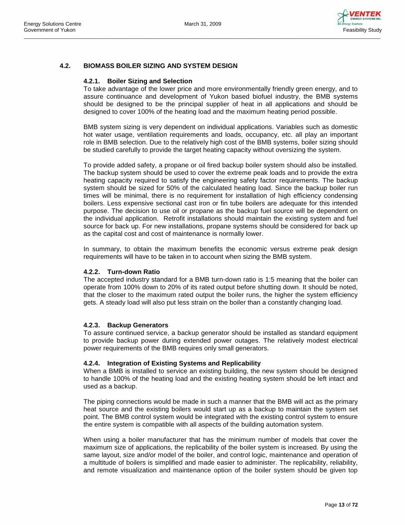
4.3.3. Fire Suppression System Protection against back-burn into the fuel source is accomplished with the boiler fuel feed system. In some models, overfilling of the firebox is prevented by a photo-eye sensor which monitors the level of the embers and adjusts the feed rate accordingly. A second sensor is located in the feed auger pipe. If any burn-back is detected the fuel feed rate increases automatically advancing the fuel faster into the fire box. Some boilers run on a constant negative pressure which is considered to be a back flash safeguard. Both types of models have a final fail-safe mechanism which in the case of malfunction or power failure will introduce water into the intake module. For safety reasons and to prevent flooding, this system is not connected to the domestic water system. It consists of an approximately 25L tank, with a float-switch and an adjustable extinguisher valve. The tank is manually filled but in case the tank dries out or is not filled, the float switch will break the control circuit and switch off the boiler automatically. 4.3.4. Safety heat-exchanger In case all other safety measures fail to keep the boiler from over-heating the safety heat-exchanger is activated. This system includes a spring loaded heat activated valve that opens when the boiler water reaches the high limit set-point and floods the finned tube heat exchanger with cold domestic water, cooling the boiler water. This system does not need electrical power to operate and would typically be activated during power outage or pump failure to evacuate the excess heat from the boiler. 4.3.5. Accumulator Tank The accumulator tank is installed in the piping system to control or buffer the swings in system temperatures when the BMB starts and stops. Unlike conventional boiler systems where the system shuts down and starts-up almost immediately, the BMB needs a buffer to store the heat from the boiler because of the delayed action of the start and shut down procedure. The tank size is based on the system size and is usually sized for 10 litres per 1 kW of boiler output. The tanks are equipped with three or five sensors, depending on the size of the system, which monitor the tank temperature at different levels. The temperatures are averaged and sent as a signal to the main control system which in turn analyzes the temperatures and predetermines the start and stop times, and the fuel feed rate, much the same way as an outdoor controller anticipates changes in outdoor air temperatures.
Energy Solutions Centre March 31, 2009 Government of Yukon Feasibility Study _________________________________________________________________________________________________________________________
Page 18 of 72
Figure 4.3.5. Accumulator Tank Installation in a Shipping Container
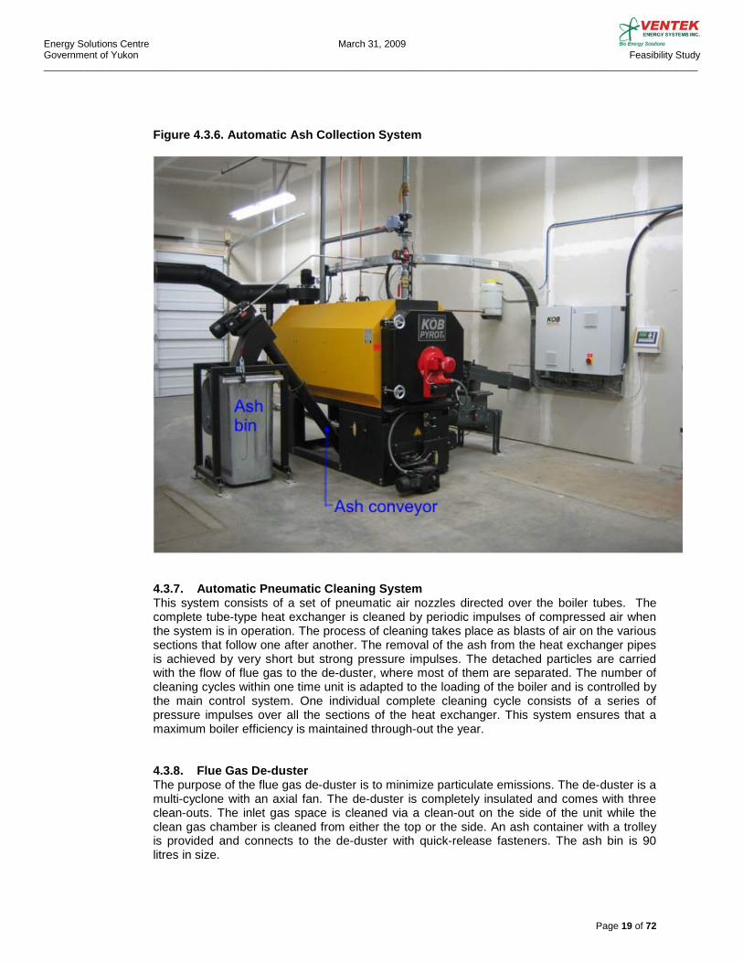
4.3.6. Automatic Ash Collection System The Automatic ash collection system is a very necessary component that allows for reduced maintenance and nuisance shut-downs. The component consists of an ash extraction auger that feeds into a sealed external metal container. They are available in sizes from 240 litres to 800 litres. A photo eye barrier-control system keeps the level of the ash constant over the auger. As a result, the ash in the ash pan can burn out and in normal operation allows for only cool ash that has burned out to be conveyed into the container. The container has an easy disconnect mechanism from the auger and is equipped with wheels, so the entire sealed container can be wheeled out and emptied in to a larger ash disposal bin exterior of the building. The size of the exterior bin, ease of transfer and final dumping to the landfill should be considered in the system design.
Energy Solutions Centre March 31, 2009 Government of Yukon Feasibility Study _________________________________________________________________________________________________________________________
Page 19 of 72
Figure 4.3.6. Automatic Ash Collection System
4.3.7. Automatic Pneumatic Cleaning System This system consists of a set of pneumatic air nozzles directed over the boiler tubes. The complete tube-type heat exchanger is cleaned by periodic impulses of compressed air when the system is in operation. The process of cleaning takes place as blasts of air on the various sections that follow one after another. The removal of the ash from the heat exchanger pipes is achieved by very short but strong pressure impulses. The detached particles are carried with the flow of flue gas to the de-duster, where most of them are separated. The number of cleaning cycles within one time unit is adapted to the loading of the boiler and is controlled by the main control system. One individual complete cleaning cycle consists of a series of pressure impulses over all the sections of the heat exchanger. This system ensures that a maximum boiler efficiency is maintained through-out the year.
4.3.8. Flue Gas De-duster The purpose of the flue gas de-duster is to minimize particulate emissions. The de-duster is a multi-cyclone with an axial fan. The de-duster is completely insulated and comes with three clean-outs. The inlet gas space is cleaned via a clean-out on the side of the unit while the clean gas chamber is cleaned from either the top or the side. An ash container with a trolley is provided and connects to the de-duster with quick-release fasteners. The ash bin is 90 litres in size.
Energy Solutions Centre March 31, 2009 Government of Yukon Feasibility Study _________________________________________________________________________________________________________________________
Page 20 of 72
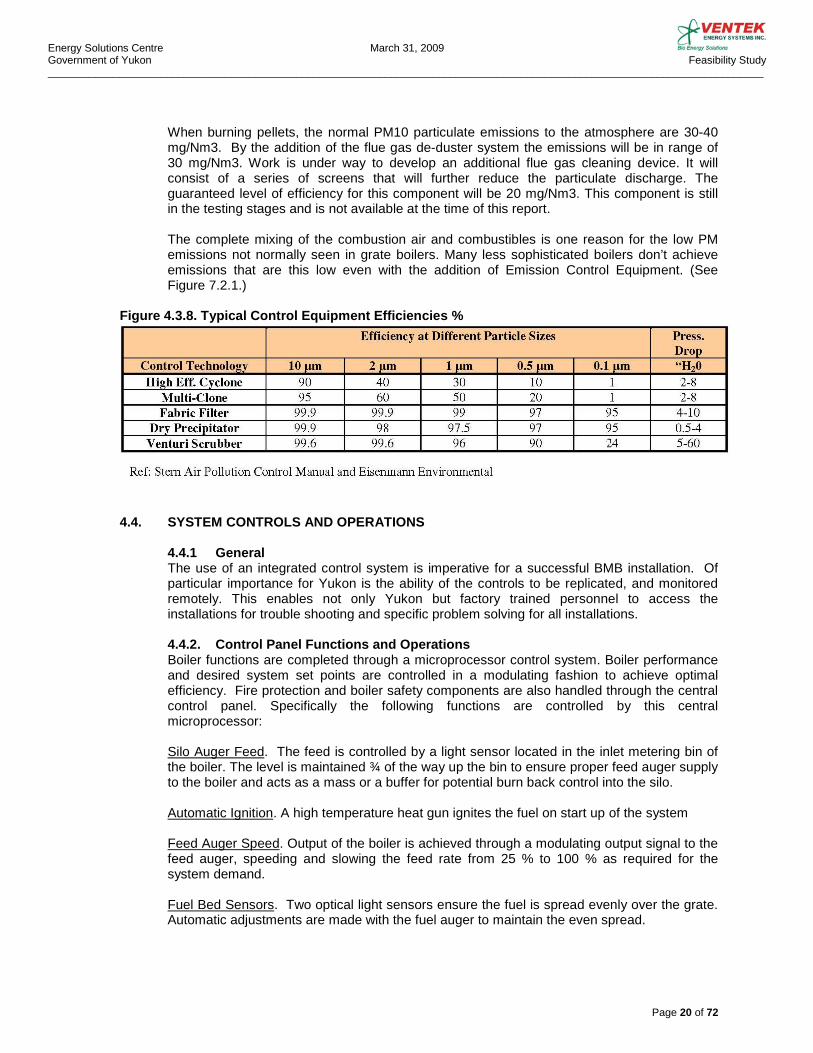
When burning pellets, the normal PM10 particulate emissions to the atmosphere are 30-40 mg/Nm3. By the addition of the flue gas de-duster system the emissions will be in range of 30 mg/Nm3. Work is under way to develop an additional flue gas cleaning device. It will consist of a series of screens that will further reduce the particulate discharge. The guaranteed level of efficiency for this component will be 20 mg/Nm3. This component is still in the testing stages and is not available at the time of this report. The complete mixing of the combustion air and combustibles is one reason for the low PM emissions not normally seen in grate boilers. Many less sophisticated boilers don’t achieve emissions that are this low even with the addition of Emission Control Equipment. (See Figure 7.2.1.)
Figure 4.3.8. Typical Control Equipment Efficiencies %
4.4. SYSTEM CONTROLS AND OPERATIONS 4.4.1 General The use of an integrated control system is imperative for a successful BMB installation. Of particular importance for Yukon is the ability of the controls to be replicated, and monitored remotely. This enables not only Yukon but factory trained personnel to access the installations for trouble shooting and specific problem solving for all installations. 4.4.2. Control Panel Functions and Operations Boiler functions are completed through a microprocessor control system. Boiler performance and desired system set points are controlled in a modulating fashion to achieve optimal efficiency. Fire protection and boiler safety components are also handled through the central control panel. Specifically the following functions are controlled by this central microprocessor: Silo Auger Feed. The feed is controlled by a light sensor located in the inlet metering bin of the boiler. The level is maintained ¾ of the way up the bin to ensure proper feed auger supply to the boiler and acts as a mass or a buffer for potential burn back control into the silo. Automatic Ignition. A high temperature heat gun ignites the fuel on start up of the system Feed Auger Speed. Output of the boiler is achieved through a modulating output signal to the feed auger, speeding and slowing the feed rate from 25 % to 100 % as required for the system demand. Fuel Bed Sensors. Two optical light sensors ensure the fuel is spread evenly over the grate. Automatic adjustments are made with the fuel auger to maintain the even spread.
Energy Solutions Centre March 31, 2009 Government of Yukon Feasibility Study _________________________________________________________________________________________________________________________
Page 21 of 72
Exhaust ID Fan. The exhaust ID fan, located down-stream of the boiler in the main stack, modulates as required to maintain the boiler output. The control panel processes input signals from a temperature and oxygen sensor in the stack. Optimal levels are 160 °C and 6 % O2. Constant adjustments in exhaust fan speed are required to meet boiler output and optimal efficiency. The primary air damper and the damper in the air turbulator fan located at the front of the boiler are adjusted at the same time, ensuring the best possible mix of air at any given fuel delivery speed. This controls component is known as the emissions optimized control circuit. Fuel Grate. The fuel bed combustion grates operate in a back and forth motion, keeping the fuel moving and mixed to ensure complete combustion before dropping to the ash collection area below. The grates are powered by a single servo drive motor and controlled by the central control panel. Boiler Mixing Valve. The return water temperature is controlled by an electronic mixing valve. The minimum return temperature to the boiler is controlled by mixing the supply and return water and is set to 65 °C. Normal operations are supply 90 °C and return 70 °C. Excess Temperature. The central control panel monitors the boiler temperature, and in the case of excess temperature a series of control functions are put into play. First course of action is to stop the fuel feed, followed by an increase in the exhaust ID fan speed, thus evacuating the boiler of excess heat. As a last result the safety heat exchanger is flooded with water to drop the boiler temperature.
Burn Back Protection. A temperature sensor is located in the auger feed tube. If an increase in temperature is detected the feed auger speeds up to carry the potential burn-back material into the combustion chamber. A second sensor is located in the metering bin. If excess temperature is detected in this area a controlled amount of water is dumped into the bin, thus dousing the potential burn-back. The dousing system is not reliant on electricity but rather a component similar to a sprinkler head. The container holding the water is equipped with a float system. If the system is triggered and the float drops, the boiler control circuit is interrupted and an error message is processed by the control panel. If the water in the container runs out, the boiler shuts down.
4.4.3. Error Messages Malfunctions on any of the functions, and appropriate components listed above, will result in an error message. These error messages can be sent or forwarded by a number of different methods including, fax, text messages, or by modem.
4.5. BACKUP BOILER AND SYSTEM CONTROLS
The backup boiler system should be designed to provide 50% of the calculated total building heating capacity including the domestic hot water heating, and should be either a propane or oil fired system. Depending on the sizing of the main boiler system, the backup boiler may not only be required as a backup, but may also be required to fire at the low end of the heating load if the low load is below the main boiler’s turn down capability. This will have to be analyzed case by case. The backup boiler is normally set to a lower operating temperature than the BMB system. In the case of a failure of the BMB system the temperature of the system would fall to the operating set point of the backup boiler and in turn start the backup boilers automatically.
Energy Solutions Centre March 31, 2009 Government of Yukon Feasibility Study _________________________________________________________________________________________________________________________
Page 22 of 72
4.6. BOILER HOUSE 4.6.1 Site Requirements The boiler house is a building or room that houses not only the boiler but the accumulator tank, pumps, mixing valves, ash collection system, flue gas cleaning system, and controls terminal. There are several different possibilities for housing the boiler and boiler components. These are discussed below in sections 4.6.2 through 4.6.5
Site requirements are dependent on if the installation is new or an addition to an existing system. The following sections will detail requirements for the individual applications. Key items to address are: - Access for maintenance, fuel trucks and snow clearing equipment - Fire Code requirements for clearance to existing buildings, fuel storage tanks etc. - Prevailing wind direction and adjacent occupancies for emissions - Esthetics - Ground and soil conditions
4.6.2. Retrofit Installations, Internal In most cases there is not enough room in existing boiler rooms to house a new BMB. Each application needs to be evaluated for clearances, adequate room for proper maintenance, ash removal, chimney or vent installation, combustion/ventilation air, and potential conflicts with existing structures.
4.6.3. Retrofit Installations, External If the existing boiler room is not suitable for the addition of the BMB, an external boiler house needs to be constructed exterior to the building taking into account the above mentioned site requirements. Two options exist, the construction of a new boiler house from the ground up or the use of 20 or 40 foot shipping containers. In either situation proper footings and foundations are required as per local codes to support not only the building or container but the storage silo and chimney as well. The container option is suitable for installations up to the 540kW in size. The benefit of this option is that the entire boiler house with all components as listed above can be installed prior to site delivery. This may provide a significant advantage in the Yukon with the many remote sites and possible shortage of personnel and materials. Foundations and pre piping of the systems can be done prior to the delivery of the boiler house to fit into shorter windows of available construction times and schedules. Piping can be routed overhead or underground depending on the specific application. Strict insulating practices need to be adhered to. Extreme weather conditions in the Yukon mean that the containers need to be insulated by an exterior shell, by construction of an outer shell or the use of pre-fabricated insulated panels.
Energy Solutions Centre March 31, 2009 Government of Yukon Feasibility Study _________________________________________________________________________________________________________________________
Page 23 of 72
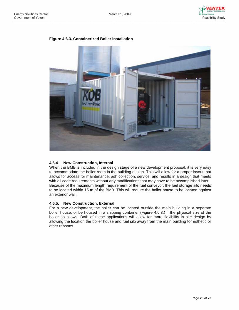
Figure 4.6.3. Containerized Boiler Installation
4.6.4 New Construction, Internal When the BMB is included in the design stage of a new development proposal, it is very easy to accommodate the boiler room in the building design. This will allow for a proper layout that allows for access for maintenance, ash collection, service; and results in a design that meets with all code requirements without any modifications that may have to be accomplished later. Because of the maximum length requirement of the fuel conveyor, the fuel storage silo needs to be located within 15 m of the BMB. This will require the boiler house to be located against an exterior wall.
4.6.5. New Construction, External For a new development, the boiler can be located outside the main building in a separate boiler house, or be housed in a shipping container (Figure 4.6.3.) if the physical size of the boiler so allows. Both of these applications will allow for more flexibility in site design by allowing the location the boiler house and fuel silo away from the main building for esthetic or other reasons.
Energy Solutions Centre March 31, 2009 Government of Yukon Feasibility Study _________________________________________________________________________________________________________________________
Page 24 of 72
4.7. FUEL STORAGE
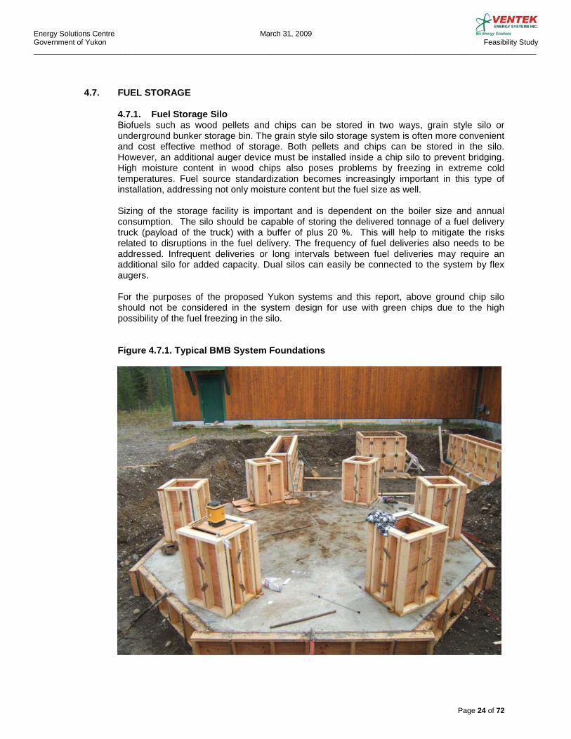
4.7.1. Fuel Storage Silo Biofuels such as wood pellets and chips can be stored in two ways, grain style silo or underground bunker storage bin. The grain style silo storage system is often more convenient and cost effective method of storage. Both pellets and chips can be stored in the silo. However, an additional auger device must be installed inside a chip silo to prevent bridging. High moisture content in wood chips also poses problems by freezing in extreme cold temperatures. Fuel source standardization becomes increasingly important in this type of installation, addressing not only moisture content but the fuel size as well. Sizing of the storage facility is important and is dependent on the boiler size and annual consumption. The silo should be capable of storing the delivered tonnage of a fuel delivery truck (payload of the truck) with a buffer of plus 20 %. This will help to mitigate the risks related to disruptions in the fuel delivery. The frequency of fuel deliveries also needs to be addressed. Infrequent deliveries or long intervals between fuel deliveries may require an additional silo for added capacity. Dual silos can easily be connected to the system by flex augers. For the purposes of the proposed Yukon systems and this report, above ground chip silo should not be considered in the system design for use with green chips due to the high possibility of the fuel freezing in the silo. Figure 4.7.1. Typical BMB System Foundations
Energy Solutions Centre March 31, 2009 Government of Yukon Feasibility Study _________________________________________________________________________________________________________________________
Page 25 of 72
5.0. BIOMASS FUELS
5.1. BIOMASS FUELS GENERAL
Biomass fuel can be derived from practically any organic matter. However, it is normally produced from various plants such as different types of grass and trees. This study concentrates on fuels derived from trees since it is the only practical source of biofuel in the Yukon. Biofuels can be combusted in various forms such as logs, hog fuel, chips, pellets etc. Pellets can be produced from the plant material itself or from more refined products such as paper, cardboard etc. Since paper does not contain lignin, the essential binder required to keep the pellets intact, the process to produce paper pellets is somewhat different from the process where wood pellets are produced. Paper may also contain traces of harmful substances created in the process of bleaching, coating, printing etc. For the purpose of this study, only two wood based biofuels are evaluated, wood pellets (Pellets) and wood chips (Chips). Unlike hydrocarbon based fossil fuels such as natural gas (CH4) or propane (C3H8), wood based fuels contain on an average (bone dry weight bases) 50% carbon, 41% oxygen, 6% hydrogen, 1% nitrogen and 2% ash. Wood fuels also contain water (roughly 5% by weight in pellets, 50% by weight in green chips and 20% by weight in dried chips) which has to be evaporated during combustion and which adds to the combustion losses.
When burning wood fuels in a boiler, apart from the combustion losses caused by the moisture contained in the fuel, additional losses occur due to radiation (through the boiler); as flue gas losses (hot gases released to the atmosphere); as unburned fuel losses (unburned carbon released with grate ash or fly ash), and as losses due to evaporation of the water formed by the combustion of hydrogen. While the losses caused by evaporation of the moisture in the fuel and evaporation of the water formed by combustion of hydrogen make up the difference in higher and lower heating values; the losses caused by radiation, flue gas and un-burned carbon form part of the boiler efficiency. Boiler efficiency is also influenced by (excess) air that is introduced in to the boiler as combustion air. The moisture content of the fuel plays an important role in the wood fuel’s heating value. Because of this, it is very important that different fuels or fuels from different suppliers be all compared on the same basis. For example, if pellets and chips are produced from the same Lodgepole Pine tree, they both have the same theoretical gross heating value when expressed on bone dry basis HHV = 19.9 GJ/Tonne or 8,590 Btu/lb. When expressed as pellets with 5% moisture HHV is 18.9 GJ/Tonne or 8,160 Btu/lb; or as green chips with 50% moisture HHV is 9.9 GJ/Tonne or 4,295 Btu/lb. As seen, the gross heating value per Tonne of fuel is very different. The lower or net heating value, the heat that is actually available for heating from the fuel in question, would be 17.4 GJ/Tonne or 7,530 Btu/lb for pellets containing 5% moisture and 8.0 GJ/Tonne or 3,440 Btu/lb for chips with 50% moisture content.
Energy Solutions Centre March 31, 2009 Government of Yukon Feasibility Study _________________________________________________________________________________________________________________________
Page 26 of 72
5.2. PELLETS
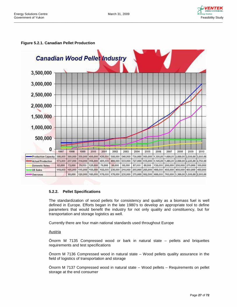
5,2,1, Security of Pellet supply To fully understand the future and security of pellets as a fuel source, it is important to note the present supply chain and growth potential in Canada and throughout the world. Although the pellet industry is relatively new in Canada it has been well established in Europe for decades. The addition of the carbon credits available for conversions from fossil fuels to biofuels has increased the demand globally. The growth of the pellet industry in Canada and throughout the world has been growing exponentially. Currently there are 29 pellet plants in Canada with projected production volumes to exceed 2 million tonnes in 2008. In 1991 300,000 tonnes were produced in Canada.
In BC there are 9 pellet plants producing roughly 935,000 tonnes of pellets or almost 1/2 of the Canadian Production of which 85 % is currently sold overseas to large industrial and electricity producers.
It is estimated that the Pine Beetle infestation in B.C. has affected approximately 130,000 km2 of forest land and at least 600,000,000 m3 of timber. A conversion by the Canadian Wood Pellet Industry states that this volume is equal to 150,000,000 tonnes of wood pellets or 2,700,000,000 GJ of energy. This would translate to roughly 73 GL of #2 fuel oil (73m x 1km x 1km). This information changes constantly as the beetle epidemic advances. It should also be noted that not all available fibre is economically viable to utilize due to the distance to the mills, state of decay, etc. In Yukon, where fire is the main forest disturbance agent, several operable areas exist for possible forest harvest for biofuel. According to the Yukon Energy, Mines and Resources, Forest Management Branch estimates, the harvestable volume in Dawson region is estimated to be 110,000 m3/yr to 275,000 m3/yr, in Whitehorse region 25,000 m3/yr to 65,000 m3/yr, and in Watson Lake region 425,000 m3/yr to 1,062,000 m3/yr. Without knowing the exact moisture content of the harvestable timber but assuming it is “seasoned”, this volume if utilized would translate to roughly 96 million to 241 million litres of fuel oil per year.
With the increasing cost of ship transportation Canadian pellet producers are looking to increase their domestic and Canadian sales. Pellets are a global commodity and as such subject to swings in pricing due to rising shipping cost, and supply and demand. To date the pellet prices globally have been very stable with no extreme spikes or dips. Considering the high cost and the high carbon footprint of transportation if pellets were to be imported from B.C. or Alberta, the projected future demand of pellets, and the availability of large volumes of fibre in Yukon, a Yukon based pellet industry - even subsidized - should be seriously considered.
Energy Solutions Centre March 31, 2009 Government of Yukon Feasibility Study _________________________________________________________________________________________________________________________
Page 27 of 72
Figure 5.2.1. Canadian Pellet Production
5.2.2. Pellet Specifications
The standardization of wood pellets for consistency and quality as a biomass fuel is well defined in Europe. Efforts began in the late 1980’s to develop an appropriate tool to define parameters that would benefit the industry for not only quality and constituency, but for transportation and storage logistics as well.
Currently there are four main national standards used throughout Europe
Austria
Önorm M 7135 Compressed wood or bark in natural state – pellets and briquettes requirements and test specifications
Önorm M 7136 Compressed wood in natural state – Wood pellets quality assurance in the field of logistics of transportation and storage
Önorm M 7137 Compressed wood in natural state – Wood pellets – Requirements on pellet storage at the end consumer
Energy Solutions Centre March 31, 2009 Government of Yukon Feasibility Study _________________________________________________________________________________________________________________________
Page 28 of 72
Sweden
SS 18 71 20 This standard defines quality parameters for fuel pellets. Three different classes of pellets are references for size and ash content.
Eight sub sections of this standard are in place. They cover moisture content, ash content, mineral fuels, sulphur content, bulk densities, mechanical strengths, calorific values, and chlorine content.
Germany
DIN 51731 Certification of pellets in Germany is based on Standard DIN 51731 and covers initial assessment, conformity and periodic surveillance.
Italy
CTI – R 04/5 This standard was developed in 2004 for solid biofuels and gives quality parameters for bio pellets for energy purposes and relates to technical standard CEN/TCC335. ( see below )
European Union
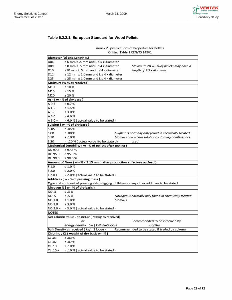
In the spring of 2006 the European Committee for Standardization, CEN, began the process of developing 30 separate technical specifications for solid biofuels such as wood pellets and wood chips, CEN/TC 335. The two most important specifications are CEN 14961, classification and specifications and CEN 15234, quality assurance. The technical papers are still in draft form and are not ready for implementation by all the European members at the time of this report, but it expected this will be the standard adopted by many non EU countries as well.
Energy Solutions Centre March 31, 2009 Government of Yukon Feasibility Study _________________________________________________________________________________________________________________________
Page 29 of 72
Table 5.2.2.1. European Standard for Wood Pellets
Energy Solutions Centre March 31, 2009 Government of Yukon Feasibility Study _________________________________________________________________________________________________________________________
Page 30 of 72
Canadian Pellet Standards
At this time a pellet standard does not exist in Canada. However, pellet producers do use the ISO standard 1928-95, “Solid Mineral Fuels – Determination of Gross Calorific Value by the Bomb Calorimetric Method and Calculation of Net Calorific Value.” With the majority of the Canadian production going overseas, Canadian producers are bound by the standards set in Europe. Wood Pellets are sold by the calorific value and the final independent tests are completed for net calorific values once the shipment reaches its port of call.
General Characteristics for Biofuel Quality
There are two basic criteria for judging biofuel quality: chemical - compositional characteristics and physical characteristics.
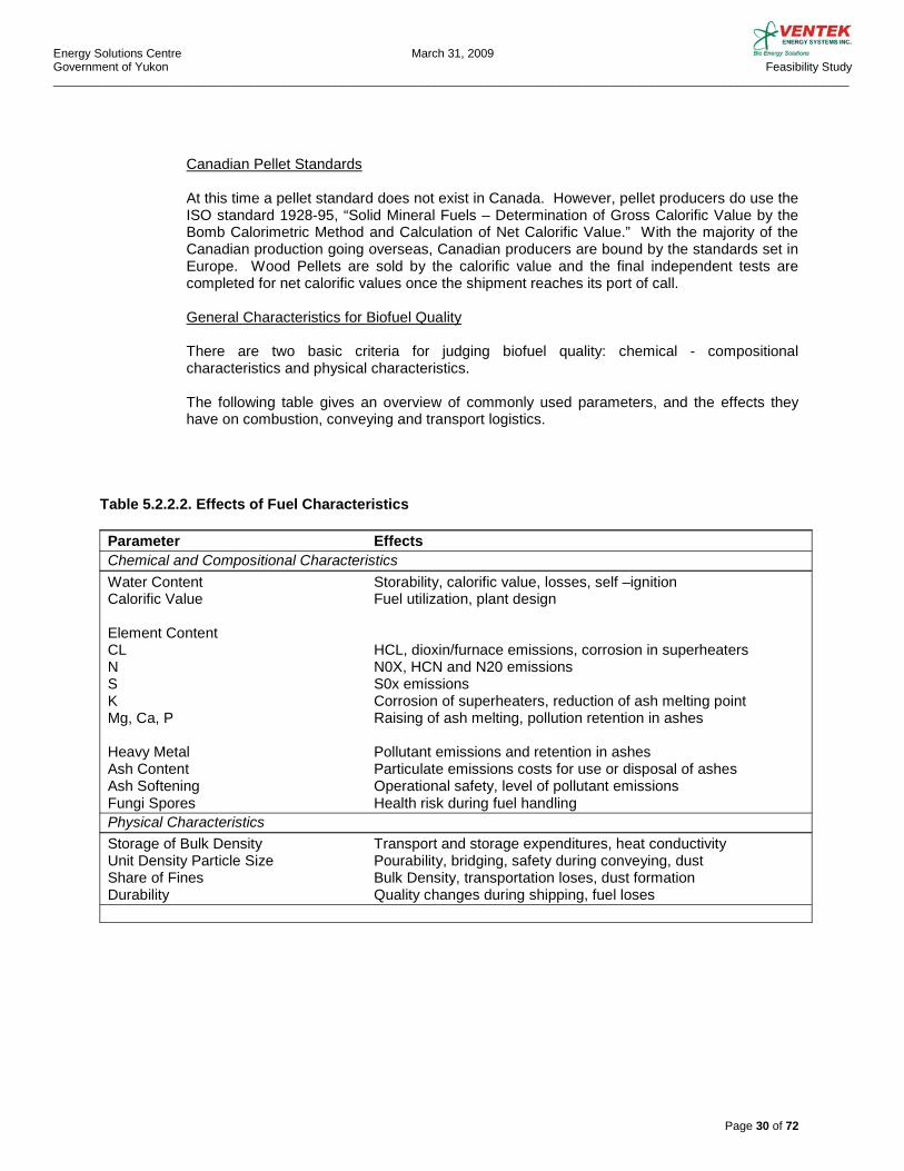
The following table gives an overview of commonly used parameters, and the effects they have on combustion, conveying and transport logistics.
Table 5.2.2.2. Effects of Fuel Characteristics
Parameter Effects Chemical and Compositional Characteristics Water Content Storability, calorific value, losses, self –ignition Calorific Value Fuel utilization, plant design Element Content CL HCL, dioxin/furnace emissions, corrosion in superheaters N N0X, HCN and N20 emissions S S0x emissions K Corrosion of superheaters, reduction of ash melting point Mg, Ca, P Raising of ash melting, pollution retention in ashes Heavy Metal Pollutant emissions and retention in ashes Ash Content Particulate emissions costs for use or disposal of ashes Ash Softening Operational safety, level of pollutant emissions Fungi Spores Health risk during fuel handling Physical Characteristics Storage of Bulk Density Transport and storage expenditures, heat conductivity Unit Density Particle Size Pourability, bridging, safety during conveying, dust Share of Fines Bulk Density, transportation loses, dust formation Durability Quality changes during shipping, fuel loses

Energy Solutions Centre March 31, 2009 Government of Yukon Feasibility Study _________________________________________________________________________________________________________________________
Page 31 of 72
Figure 5.2.2.Comparison of European Fuel Oil and Pellet Prices
5.3. CHIPS
5.3.1. Security of Chip Supply Unlike wood pellets, wood chips are not a commonly globally traded commodity. This lack of supply or organized supply chain results in a very unstable and insecure supply of wood chips at the present time. Currently there are no large scale facilities in British Columbia or Yukon that produce wood chips for fuel only. It is important to note that strict adherence to wood chip fuel specifications is critical in the process of producing chips that will result in proper operation of a BMB system. The success of a chip industry in Yukon is dependent on a number of factors. An adequate supply of high quality raw material and steady demand for chips is required to offset the relatively high capital cost of quality equipment needed to produce high quality chips required for proper combustion in a BMB. Factors such as bulk density and moisture content and their inherent effects on transportation of net energy need to be analyzed for each installation. Each of these is discussed in detail in the sections following.
Energy Solutions Centre March 31, 2009 Government of Yukon Feasibility Study _________________________________________________________________________________________________________________________
Page 32 of 72
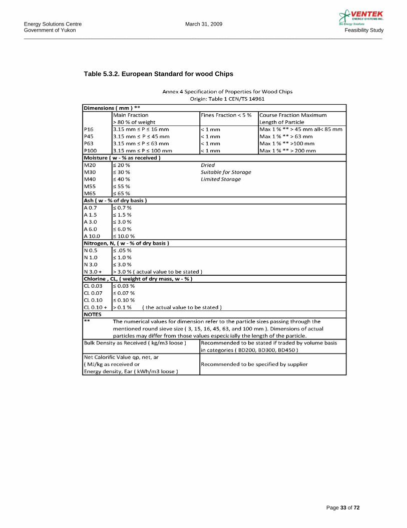
5.3.2. Chip Specifications As with wood pellets there are a number of standards developed in Europe for standardization of wood chips for use as biofuels. With the development of modern BMB systems, it has become increasingly important to develop a product that is suitable for the BMB system applications. Variations in moisture content, size of chips, consistency (white wood versus bark), percent of fines, etc. can drastically effect the operation and efficiency of a BMB system. Poor and inconsistent quality of chip supply can result in premature boiler failures, failures in the conveyor augers and drives, increased maintenance costs, increased ash disposal, and nuisance system failures. The most recognized and comprehensive standard for wood chip fuel is CEN 14961, Annex 4. shown below.
Energy Solutions Centre March 31, 2009 Government of Yukon Feasibility Study _________________________________________________________________________________________________________________________
Page 33 of 72
Table 5.3.2. European Standard for wood Chips
Energy Solutions Centre March 31, 2009 Government of Yukon Feasibility Study _________________________________________________________________________________________________________________________
Page 34 of 72
5.4. PELLETS VERSUS CHIPS
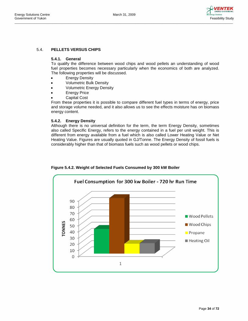
5.4.1. General To qualify the difference between wood chips and wood pellets an understanding of wood fuel properties becomes necessary particularly when the economics of both are analyzed. The following properties will be discussed. • Energy Density • Volumetric Bulk Density • Volumetric Energy Density • Energy Price • Capital Cost From these properties it is possible to compare different fuel types in terms of energy, price and storage volume needed, and it also allows us to see the effects moisture has on biomass energy content. 5.4.2. Energy Density Although there is no universal definition for the term, the term Energy Density, sometimes also called Specific Energy, refers to the energy contained in a fuel per unit weight. This is different from energy available from a fuel which is also called Lower Heating Value or Net Heating Value. Figures are usually quoted in GJ/Tonne. The Energy Density of fossil fuels is considerably higher than that of biomass fuels such as wood pellets or wood chips. Figure 5.4.2. Weight of Selected Fuels Consumed by 300 kW Boiler
Energy Solutions Centre March 31, 2009 Government of Yukon Feasibility Study _________________________________________________________________________________________________________________________
Page 35 of 72
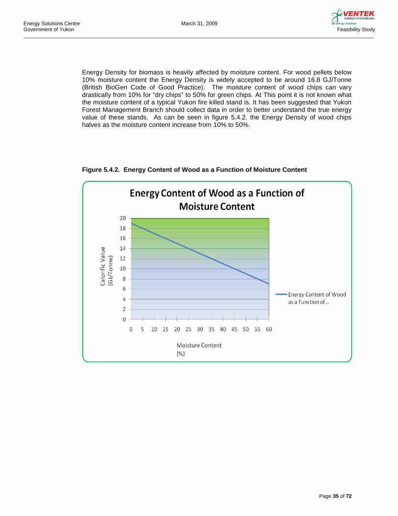
Energy Density for biomass is heavily affected by moisture content. For wood pellets below 10% moisture content the Energy Density is widely accepted to be around 16.8 GJ/Tonne (British BioGen Code of Good Practice). The moisture content of wood chips can vary drastically from 10% for “dry chips” to 50% for green chips. At This point it is not known what the moisture content of a typical Yukon fire killed stand is. It has been suggested that Yukon Forest Management Branch should collect data in order to better understand the true energy value of these stands. As can be seen in figure 5.4.2. the Energy Density of wood chips halves as the moisture content increase from 10% to 50%.
Figure 5.4.2. Energy Content of Wood as a Function of Moisture Content
Energy Solutions Centre March 31, 2009 Government of Yukon Feasibility Study _________________________________________________________________________________________________________________________
Page 36 of 72
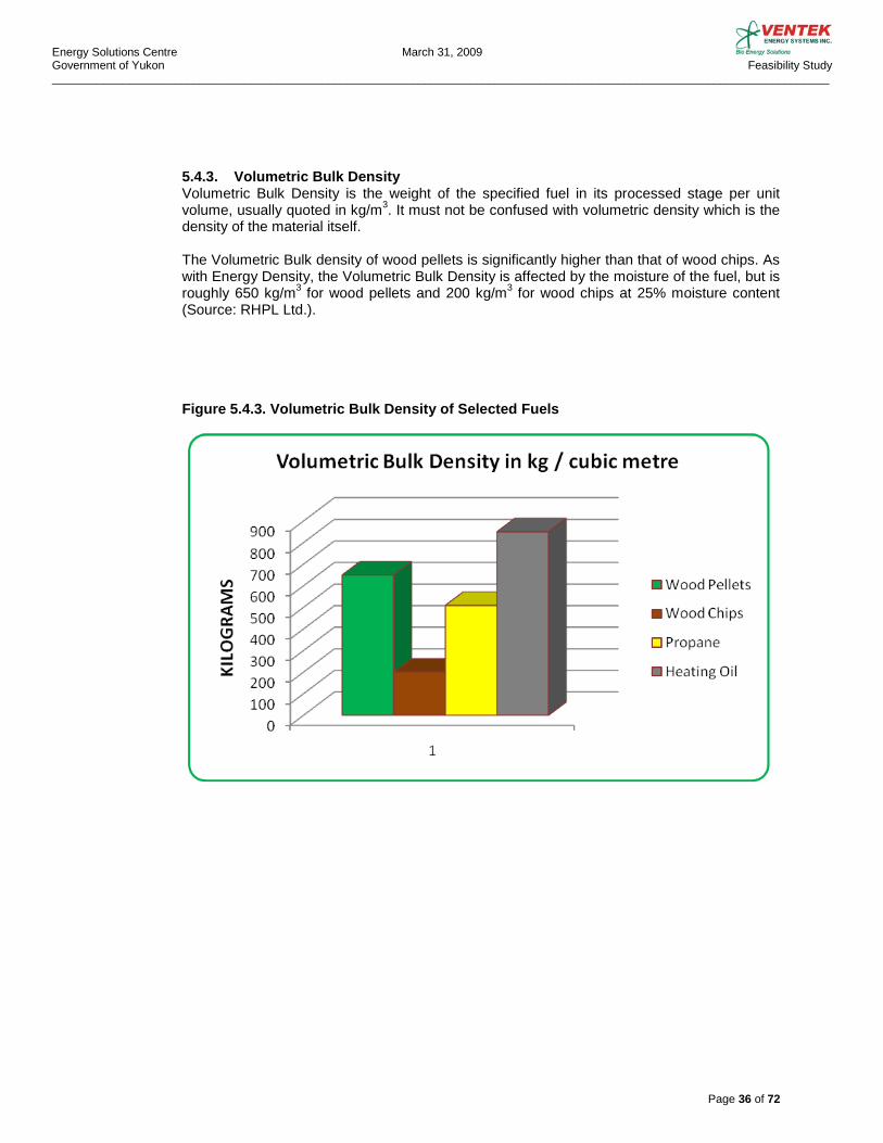
5.4.3. Volumetric Bulk Density Volumetric Bulk Density is the weight of the specified fuel in its processed stage per unit volume, usually quoted in kg/m3. It must not be confused with volumetric density which is the density of the material itself. The Volumetric Bulk density of wood pellets is significantly higher than that of wood chips. As with Energy Density, the Volumetric Bulk Density is affected by the moisture of the fuel, but is roughly 650 kg/m3 for wood pellets and 200 kg/m3 for wood chips at 25% moisture content (Source: RHPL Ltd.). Figure 5.4.3. Volumetric Bulk Density of Selected Fuels
Energy Solutions Centre March 31, 2009 Government of Yukon Feasibility Study _________________________________________________________________________________________________________________________
Page 37 of 72
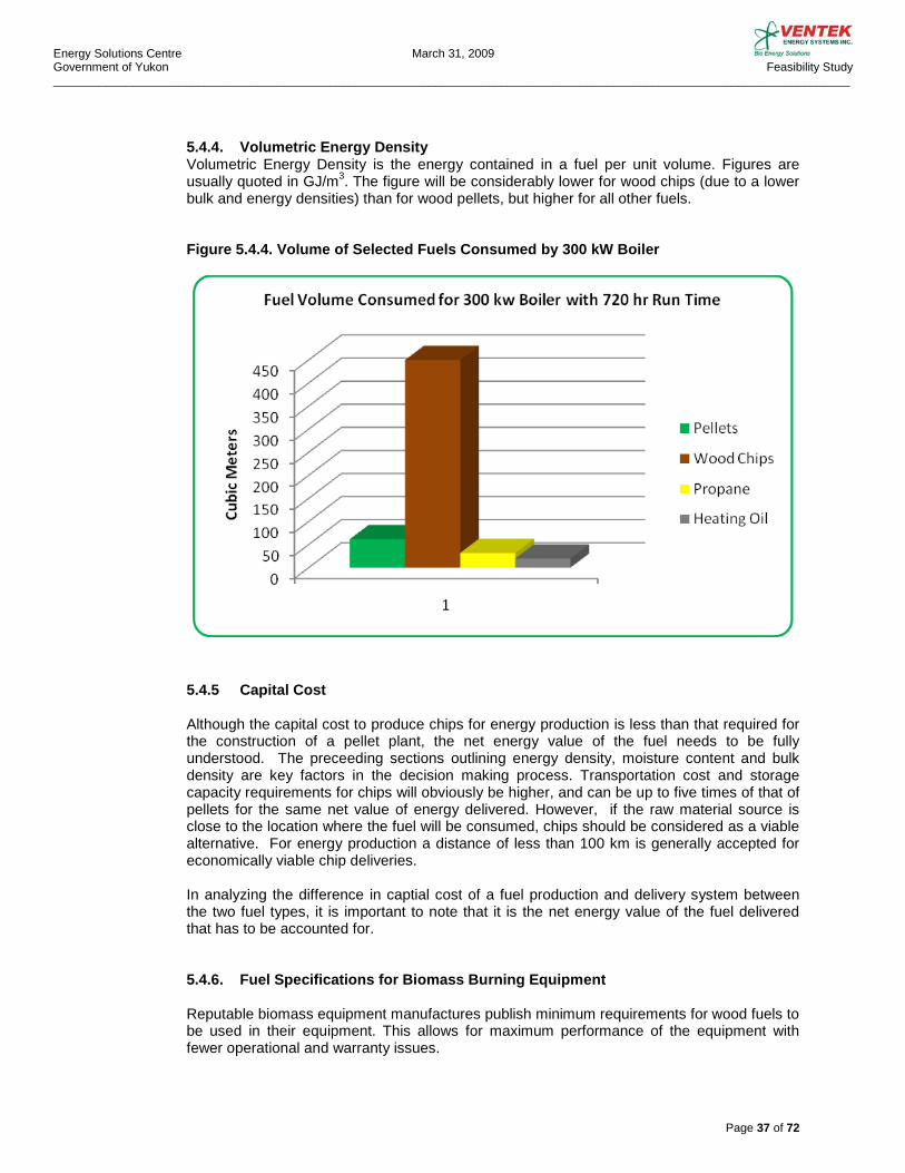
5.4.4. Volumetric Energy Density Volumetric Energy Density is the energy contained in a fuel per unit volume. Figures are usually quoted in GJ/m3. The figure will be considerably lower for wood chips (due to a lower bulk and energy densities) than for wood pellets, but higher for all other fuels. Figure 5.4.4. Volume of Selected Fuels Consumed by 300 kW Boiler
5.4.5 Capital Cost Although the capital cost to produce chips for energy production is less than that required for the construction of a pellet plant, the net energy value of the fuel needs to be fully understood. The preceeding sections outlining energy density, moisture content and bulk density are key factors in the decision making process. Transportation cost and storage capacity requirements for chips will obviously be higher, and can be up to five times of that of pellets for the same net value of energy delivered. However, if the raw material source is close to the location where the fuel will be consumed, chips should be considered as a viable alternative. For energy production a distance of less than 100 km is generally accepted for economically viable chip deliveries. In analyzing the difference in captial cost of a fuel production and delivery system between the two fuel types, it is important to note that it is the net energy value of the fuel delivered that has to be accounted for. 5.4.6. Fuel Specifications for Biomass Burning Equipment
Reputable biomass equipment manufactures publish minimum requirements for wood fuels to be used in their equipment. This allows for maximum performance of the equipment with fewer operational and warranty issues.
Energy Solutions Centre March 31, 2009 Government of Yukon Feasibility Study _________________________________________________________________________________________________________________________
Page 38 of 72
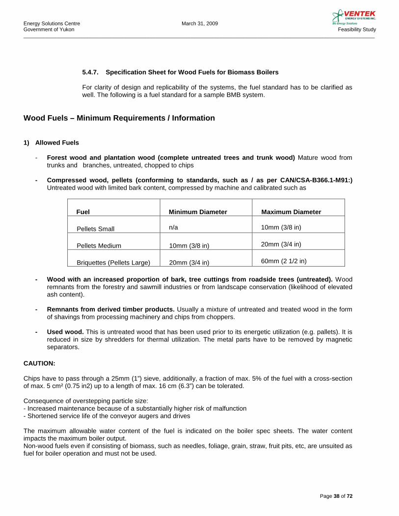
5.4.7. Specification Sheet for Wood Fuels for Biomass Boilers For clarity of design and replicability of the systems, the fuel standard has to be clarified as well. The following is a fuel standard for a sample BMB system.
Wood Fuels – Minimum Requirements / Information
1) Allowed Fuels
- Forest wood and plantation wood (complete untreated trees and trunk wood) Mature wood from
trunks and branches, untreated, chopped to chips - Compressed wood, pellets (conforming to standards, such as / as per CAN/CSA-B366.1-M91:)
Untreated wood with limited bark content, compressed by machine and calibrated such as
Fuel
Minimum Diameter
Maximum Diameter
Pellets Small
n/a
10mm (3/8 in)
Pellets Medium
10mm (3/8 in)
20mm (3/4 in)
Briquettes (Pellets Large)
20mm (3/4 in)
60mm (2 1/2 in)
- Wood with an increased proportion of bark, tree cuttings from roadside trees (untreated). Wood
remnants from the forestry and sawmill industries or from landscape conservation (likelihood of elevated ash content).
- Remnants from derived timber products. Usually a mixture of untreated and treated wood in the form
of shavings from processing machinery and chips from choppers. - Used wood. This is untreated wood that has been used prior to its energetic utilization (e.g. pallets). It is
reduced in size by shredders for thermal utilization. The metal parts have to be removed by magnetic separators.
CAUTION: Chips have to pass through a 25mm (1”) sieve, additionally, a fraction of max. 5% of the fuel with a cross-section of max. 5 cm² (0.75 in2) up to a length of max. 16 cm (6.3”) can be tolerated. Consequence of overstepping particle size: - Increased maintenance because of a substantially higher risk of malfunction - Shortened service life of the conveyor augers and drives The maximum allowable water content of the fuel is indicated on the boiler spec sheets. The water content impacts the maximum boiler output. Non-wood fuels even if consisting of biomass, such as needles, foliage, grain, straw, fruit pits, etc, are unsuited as fuel for boiler operation and must not be used.
Energy Solutions Centre March 31, 2009 Government of Yukon Feasibility Study _________________________________________________________________________________________________________________________
Page 39 of 72
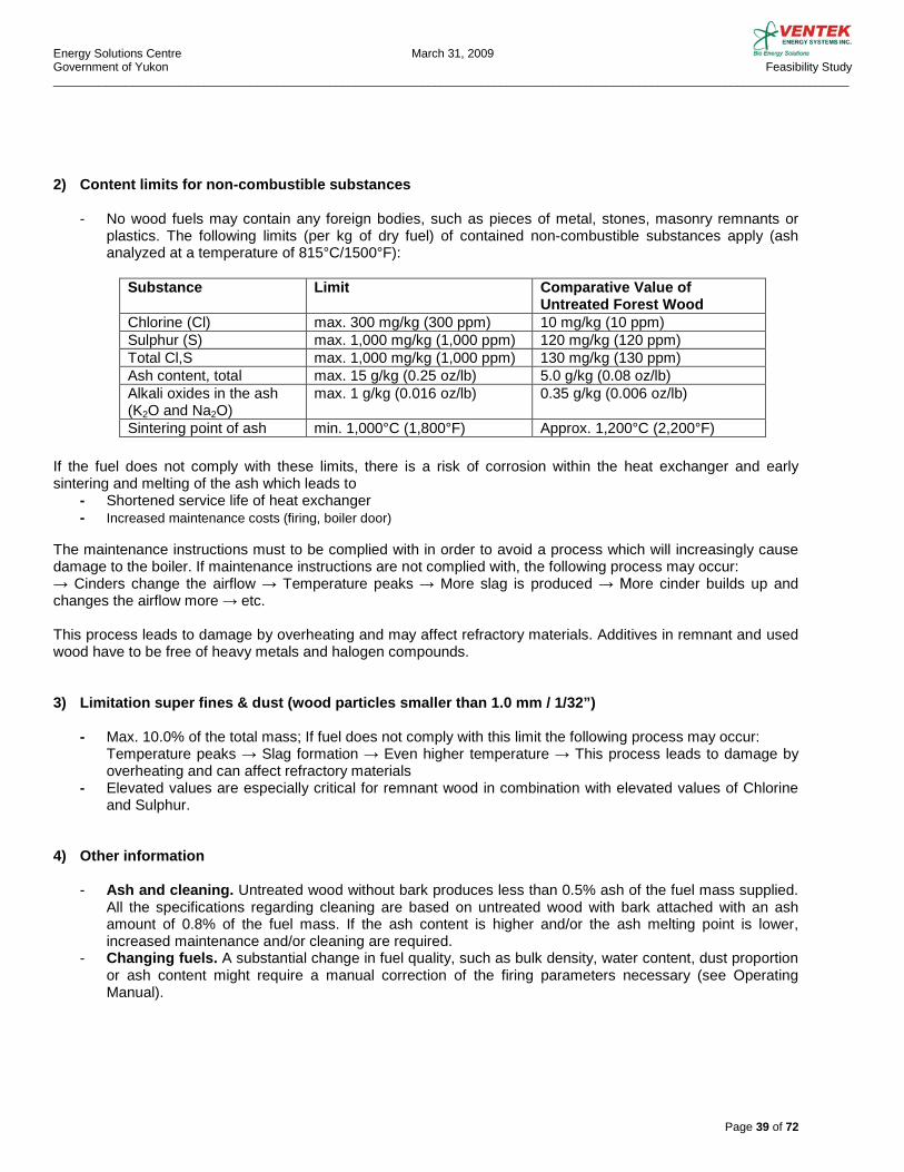
2) Content limits for non-combustible substances - No wood fuels may contain any foreign bodies, such as pieces of metal, stones, masonry remnants or
plastics. The following limits (per kg of dry fuel) of contained non-combustible substances apply (ash analyzed at a temperature of 815°C/1500°F):
Substance Limit Comparative Value of
Untreated Forest Wood Chlorine (Cl) max. 300 mg/kg (300 ppm) 10 mg/kg (10 ppm) Sulphur (S) max. 1,000 mg/kg (1,000 ppm) 120 mg/kg (120 ppm) Total Cl,S max. 1,000 mg/kg (1,000 ppm) 130 mg/kg (130 ppm) Ash content, total max. 15 g/kg (0.25 oz/lb) 5.0 g/kg (0.08 oz/lb) Alkali oxides in the ash (K2O and Na2O)
max. 1 g/kg (0.016 oz/lb) 0.35 g/kg (0.006 oz/lb)
Sintering point of ash min. 1,000°C (1,800°F) Approx. 1,200°C (2,200°F)
If the fuel does not comply with these limits, there is a risk of corrosion within the heat exchanger and early sintering and melting of the ash which leads to
- Shortened service life of heat exchanger - Increased maintenance costs (firing, boiler door)
The maintenance instructions must to be complied with in order to avoid a process which will increasingly cause damage to the boiler. If maintenance instructions are not complied with, the following process may occur: → Cinders change the airflow → Temperature peaks → More slag is produced → More cinder builds up and changes the airflow more → etc. This process leads to damage by overheating and may affect refractory materials. Additives in remnant and used wood have to be free of heavy metals and halogen compounds. 3) Limitation super fines & dust (wood particles smaller than 1.0 mm / 1/32”)
- Max. 10.0% of the total mass; If fuel does not comply with this limit the following process may occur: Temperature peaks → Slag formation → Even higher temperature → This process leads to damage by overheating and can affect refractory materials
- Elevated values are especially critical for remnant wood in combination with elevated values of Chlorine and Sulphur.
4) Other information
- Ash and cleaning. Untreated wood without bark produces less than 0.5% ash of the fuel mass supplied. All the specifications regarding cleaning are based on untreated wood with bark attached with an ash amount of 0.8% of the fuel mass. If the ash content is higher and/or the ash melting point is lower, increased maintenance and/or cleaning are required.
- Changing fuels. A substantial change in fuel quality, such as bulk density, water content, dust proportion or ash content might require a manual correction of the firing parameters necessary (see Operating Manual).
Energy Solutions Centre March 31, 2009 Government of Yukon Feasibility Study _________________________________________________________________________________________________________________________
Page 40 of 72
5.5. LIST OF FUEL SUPPLIERS The estimated global production of wood pellets in 2008 was approximately 10 million Tonnes. Of this, Canadian producers produced approximately 2 million Tonnes or 20% of the total global production. Of the Canadian production, British Columbia producers produced approximately 935,000 Tonnes or just under 50% of the Canadian production.
5.5.1. BC Pellet Producers Armstrong Pellets www.armstrongpellets.com
Box 280 Armstrong, BC V0B 1B0
Contact: Leroy Reitsma [email protected] Plant located in Armstrong, BC
Pacific Bioenergy Corporation www.pacificbioenergy.ca
Suite 1508-999 W. Hastings St. Vancouver, BC V6C 2W2 Contact: Wayne Young [email protected] Plant located in Prince George, BC
Pinnacle Pellet www.pinnaclepellet.com
4252 Dog Prairie Rd. Quesnel, BC V2J 6K9
Contact: Leroy Reitsma [email protected] Plants located in Quesnel, Williams Lake, Meadowbank near Dunkley Lumber, and joint venture with Canfor Forest Products in Houston, BC
Premium Pellet www.premiumpellet.com
Box 125 Vanderhoof, BC VOJ 3A0 Contact: Len Fox [email protected] Plant located in Vanderhoof, BC
Princeton Co-Generation www.eaglevalleypellets.com
Box 2440 Princeton, BC V0X 1W0 Contact: Richard Smith [email protected] Plant located in Princeton, BC
WestWood Fibre Products Inc. www.westwoodfibre.com
2667 Kyle Road Westbank, BC V1Z 2M9 Contact: Cliff Ramsay [email protected]

Energy Solutions Centre March 31, 2009 Government of Yukon Feasibility Study _________________________________________________________________________________________________________________________
Page 41 of 72
5.5.2. Alberta Pellet Producers Dansons Group Inc. www.dansons.com 26319 Township Road 531 Acheson, Alberta T7X 5A3 Contact: Jeff Theissen [email protected] Broker for Vanderwell Contractors (1971) Ltd. Pellet mill in Slave Lake. Foothills Forest Products Inc. www.foothillsforestproducts.com PO Box 180 Grande Cache, AB T0E-0Y0 Contact: [email protected] La Crete Sawmills Ltd. www.lacretesawmills.com Box 1090 Hwy 697 South La Crete, Alberta T0H 2H0 Contact: John Unger [email protected]
Energy Solutions Centre March 31, 2009 Government of Yukon Feasibility Study _________________________________________________________________________________________________________________________
Page 42 of 72
6.0. SYSTEMS’ MAINTENANCE
6.1. BOILER
A BMB system has a number of components that need periodic maintenance and checking to maintain continuous and trouble free operation. All maintenance functions have to be carried out by qualified personnel familiar with the system and using appropriate safety precautions and equipment. The following are typical BMB maintenance functions: - Clean photo sensor lenses and sight glasses - Clean grate - Empty ash containers and exhaust gas collector where applicable - Clean flue gas re-circulation line - Unplug ID Fan and clean impeller and fan housing - Clean heat exchanger tubes - Remove ash from the bottom of combustion chamber - Drain condensation from the automatic tube cleaning header The frequency with which these functions need to be performed depends on the type and quality of biofuel used. These maintenance items should all be listed in the boiler maintenance manual with recommended intervals.
6.2. STORAGE SYSTEM
The fuel storage system requires the minimum of maintenance. Silos should be checked periodically to detect any mechanical damage caused by vehicle collision, rusting etc. Any leaks should be investigated and sealed and the access hatch has to be kept closed to prevent water from entering the silo. The bottom slide gate needs to be inspected annually and the gear assembly lubricated.
6.3. FEED SYSTEM The feed system augers, chain drives and gear cases need regular inspection. Augers and chains should be checked for wear and tear and replaced or repaired as necessary. Chains and flange bearings should be lubricated and gear case oils changed according to maintenance schedule. Drive shaft U-joints should be lubricated where applicable.
6.4. FIRE SAFETY Metering bin fire water reservoir level has to be checked regularly and be filled if the level is too low due to evaporation or due to the safety valve having been activated. If the water level is too low and the float valve activates the alarm, the boiler will shut down.
6.5. ASH HANDLING As indicated previously, an automatic ash extraction system is recommended for the over-all ease and safety of the BMB operation. This device delivers the ash to an enclosed fireproof container that must be manually emptied periodically. A regular written maintenance schedule should address not only the frequency but the safe disposal. The ash is considered non toxic and can be used for various gardening uses or disposed of in a landfill. The ash content for white wood pellets is 0.5%.
Energy Solutions Centre March 31, 2009 Government of Yukon Feasibility Study _________________________________________________________________________________________________________________________
Page 43 of 72
6.6. MAINTENANCE PERSONNEL
One qualified person can easily take care of the periodic maintenance required by a BMB system. Some maintenance functions are required after 300 hours of boiler running time when wood chips are used as fuel, but when wood pellets are used, regular maintenance needs to be carried out every 500 to 1,000 hours of boiler running time depending of the function. Again, all these functions and maintenance intervals should be listed in the BMB maintenance manual. Yukon Public Safety Branch currently requires supervision by person holding 4th class power engineer’s certificate for systems over 750 kW in size. Regular maintenance such as cleaning and lubrication can be carried out by existing personnel currently used for servicing conventional heating equipment.
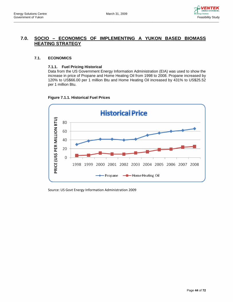
Energy Solutions Centre March 31, 2009 Government of Yukon Feasibility Study _________________________________________________________________________________________________________________________
Page 44 of 72
7.0. SOCIO – ECONOMICS OF IMPLEMENTING A YUKON BASED BIOMASS HEATING STRATEGY 7.1. ECONOMICS
7.1.1. Fuel Pricing Historical Data from the US Government Energy Information Administration (EIA) was used to show the increase in price of Propane and Home Heating Oil from 1998 to 2008. Propane increased by 120% to US$66.00 per 1 million Btu and Home Heating Oil increased by 431% to US$25.52 per 1 million Btu. Figure 7.1.1. Historical Fuel Prices Source: US Govt Energy Information Administration 2009

Energy Solutions Centre March 31, 2009 Government of Yukon Feasibility Study _________________________________________________________________________________________________________________________
Page 45 of 72
7.1.2. Fuel Pricing Future The EIA prepared an Energy Outlook in December 2008 and their projections were used to compare price projections from 2009 to 2030. All fuel prices are projected to decline in 2009 followed by steady increases as the World economy recovers. Propane is projected to increase by 54% to US$34.58 per 1 million Btu, Home Heating Oil to increase by 53.8% to US$24.70 per 1 million Btu and Pellets by 44.44% to US$9.10 per 1 million Btu by 2030. Figure 7.1.2. Future Fuel Prices Source: US Govt Energy Information Administration (biomass % increase applied to 2009 price for pellet)
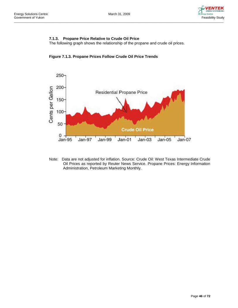
Energy Solutions Centre March 31, 2009 Government of Yukon Feasibility Study _________________________________________________________________________________________________________________________
Page 46 of 72
7.1.3. Propane Price Relative to Crude Oil Price The following graph shows the relationship of the propane and crude oil prices.
Figure 7.1.3. Propane Prices Follow Crude Oil Price Trends
Note: Data are not adjusted for inflation. Source: Crude Oil: West Texas Intermediate Crude Oil Prices as reported by Reuter News Service. Propane Prices: Energy Information Administration, Petroleum Marketing Monthly.
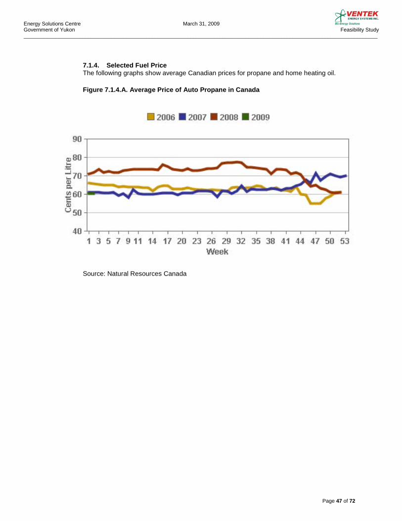
Energy Solutions Centre March 31, 2009 Government of Yukon Feasibility Study _________________________________________________________________________________________________________________________
Page 47 of 72
7.1.4. Selected Fuel Price The following graphs show average Canadian prices for propane and home heating oil.
Figure 7.1.4.A. Average Price of Auto Propane in Canada
Source: Natural Resources Canada
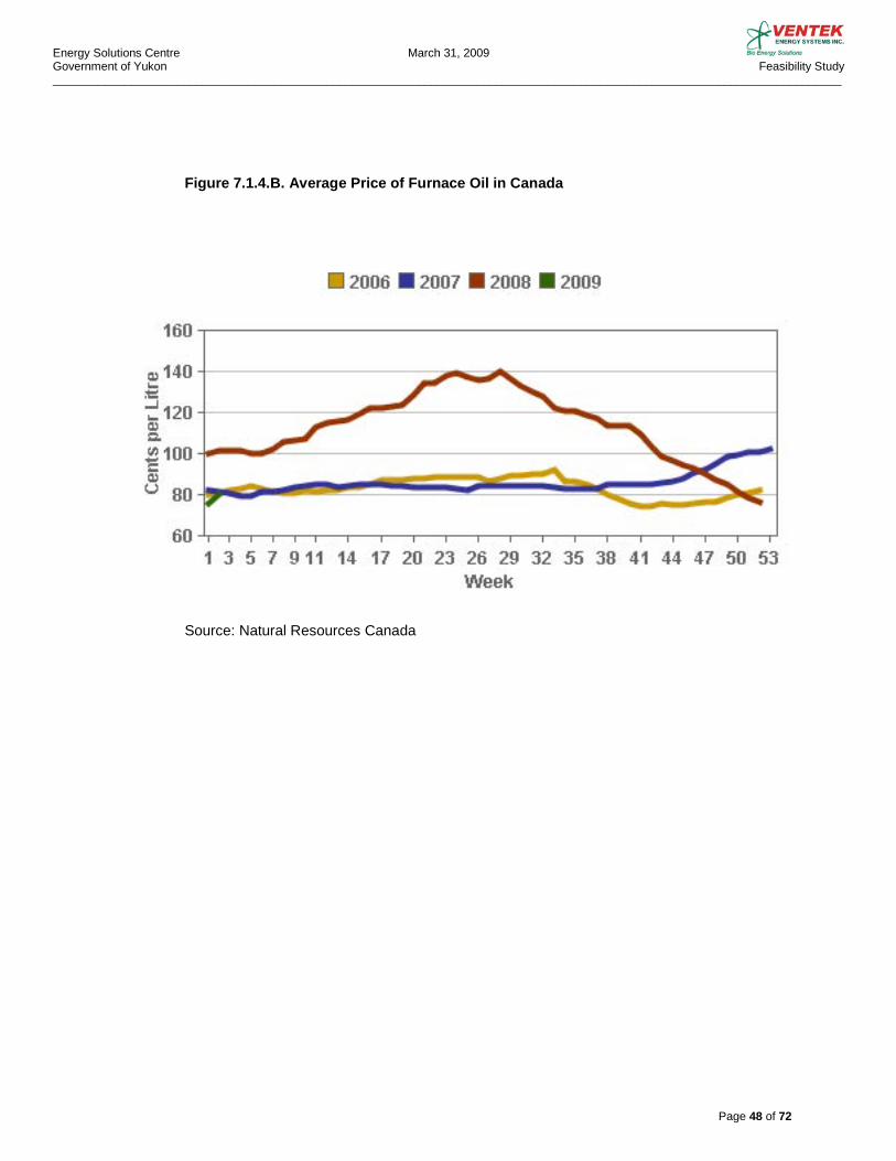
Energy Solutions Centre March 31, 2009 Government of Yukon Feasibility Study _________________________________________________________________________________________________________________________
Page 48 of 72
Figure 7.1.4.B. Average Price of Furnace Oil in Canada
Source: Natural Resources Canada
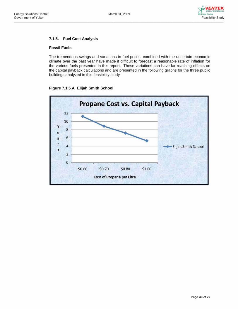
Energy Solutions Centre March 31, 2009 Government of Yukon Feasibility Study _________________________________________________________________________________________________________________________
Page 49 of 72
7.1.5. Fuel Cost Analysis Fossil Fuels The tremendous swings and variations in fuel prices, combined with the uncertain economic climate over the past year have made it difficult to forecast a reasonable rate of inflation for the various fuels presented in this report. These variations can have far-reaching effects on the capital payback calculations and are presented in the following graphs for the three public buildings analyzed in this feasibility study Figure 7.1.5.A Elijah Smith School

Energy Solutions Centre March 31, 2009 Government of Yukon Feasibility Study _________________________________________________________________________________________________________________________
Page 50 of 72
Figure 7.1.5.B Hidden Valley School
Figure 7.1.5.C Property Management Facilities Building
As can be seen, the increase in fossil fuel cost by very small percentage can result in a substantial increase in time for capital cost recovery.
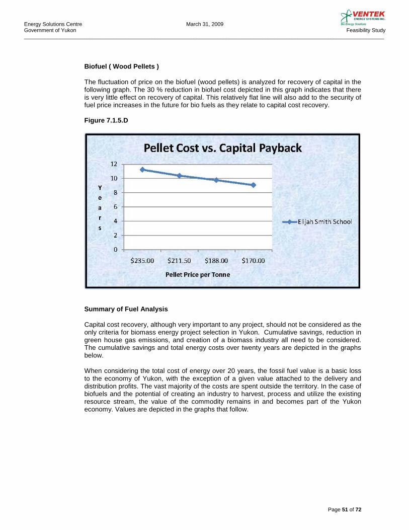
Energy Solutions Centre March 31, 2009 Government of Yukon Feasibility Study _________________________________________________________________________________________________________________________
Page 51 of 72
Biofuel ( Wood Pellets ) The fluctuation of price on the biofuel (wood pellets) is analyzed for recovery of capital in the following graph. The 30 % reduction in biofuel cost depicted in this graph indicates that there is very little effect on recovery of capital. This relatively flat line will also add to the security of fuel price increases in the future for bio fuels as they relate to capital cost recovery. Figure 7.1.5.D
Summary of Fuel Analysis Capital cost recovery, although very important to any project, should not be considered as the only criteria for biomass energy project selection in Yukon. Cumulative savings, reduction in green house gas emissions, and creation of a biomass industry all need to be considered. The cumulative savings and total energy costs over twenty years are depicted in the graphs below. When considering the total cost of energy over 20 years, the fossil fuel value is a basic loss to the economy of Yukon, with the exception of a given value attached to the delivery and distribution profits. The vast majority of the costs are spent outside the territory. In the case of biofuels and the potential of creating an industry to harvest, process and utilize the existing resource stream, the value of the commodity remains in and becomes part of the Yukon economy. Values are depicted in the graphs that follow.
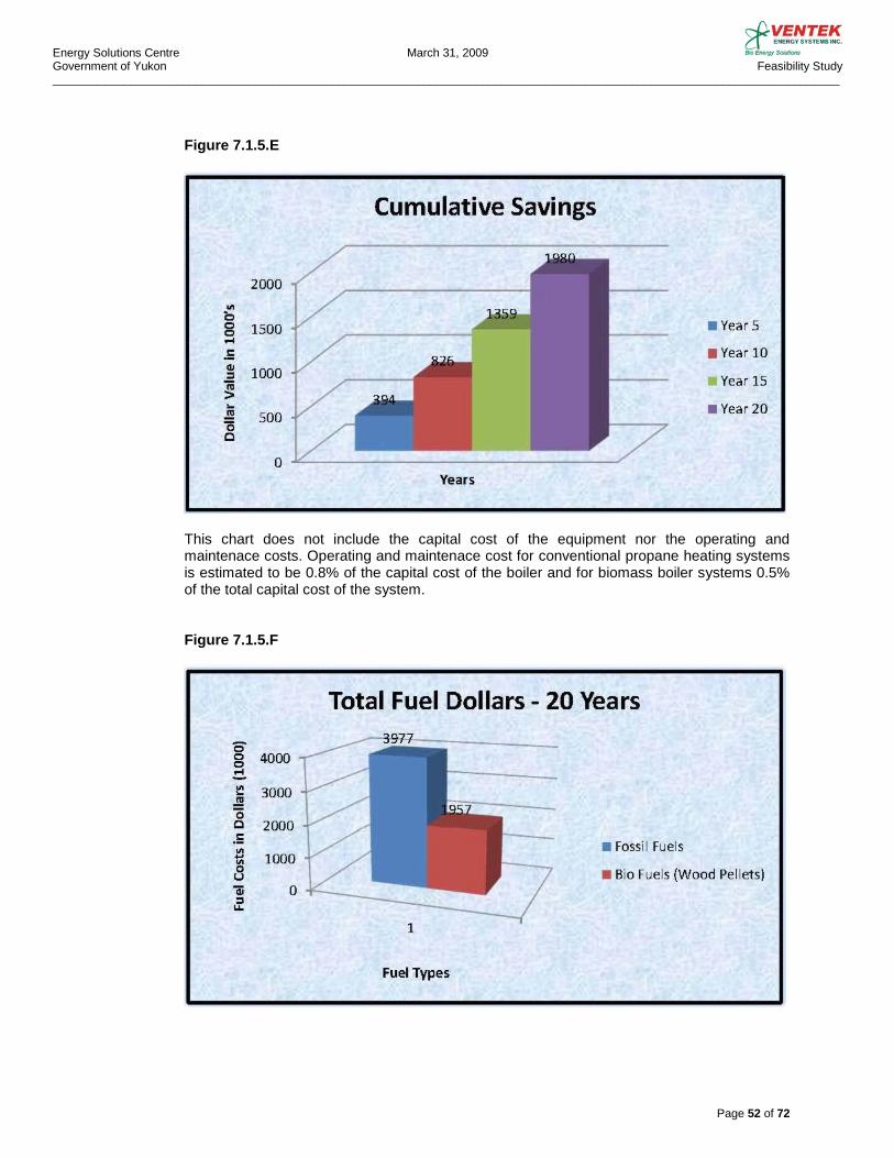
Energy Solutions Centre March 31, 2009 Government of Yukon Feasibility Study _________________________________________________________________________________________________________________________
Page 52 of 72
Figure 7.1.5.E
This chart does not include the capital cost of the equipment nor the operating and maintenace costs. Operating and maintenace cost for conventional propane heating systems is estimated to be 0.8% of the capital cost of the boiler and for biomass boiler systems 0.5% of the total capital cost of the system. Figure 7.1.5.F

Energy Solutions Centre March 31, 2009 Government of Yukon Feasibility Study _________________________________________________________________________________________________________________________
Page 53 of 72
Green House Gases The following graph illustrates the total CO2 savings for the three public buildings analyzed in this report. The total tonnage of C02 emissions saved in a twenty year period is 8,150 Tonnes. This is the equivalent of removing 150 mid size vehicles from the road for the same time period. Figure 7.1.5.G
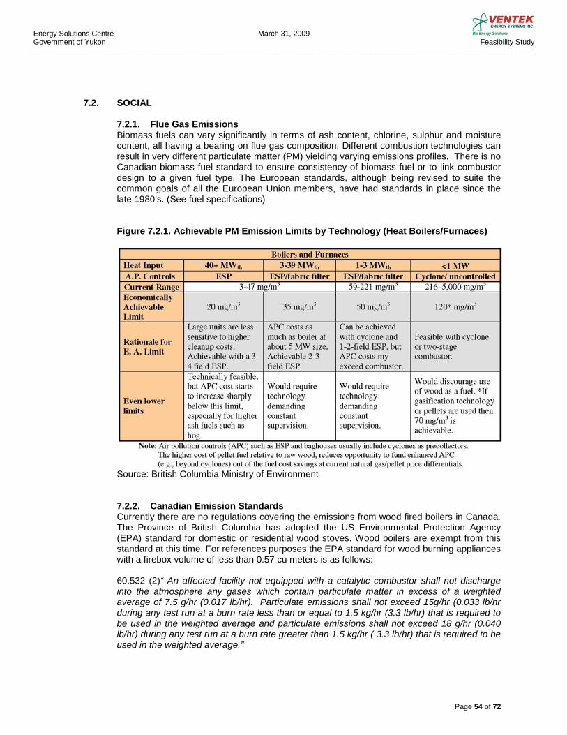
Energy Solutions Centre March 31, 2009 Government of Yukon Feasibility Study _________________________________________________________________________________________________________________________
Page 54 of 72
7.2. SOCIAL
7.2.1. Flue Gas Emissions Biomass fuels can vary significantly in terms of ash content, chlorine, sulphur and moisture content, all having a bearing on flue gas composition. Different combustion technologies can result in very different particulate matter (PM) yielding varying emissions profiles. There is no Canadian biomass fuel standard to ensure consistency of biomass fuel or to link combustor design to a given fuel type. The European standards, although being revised to suite the common goals of all the European Union members, have had standards in place since the late 1980’s. (See fuel specifications)
Figure 7.2.1. Achievable PM Emission Limits by Technology (Heat Boilers/Furnaces)
Source: British Columbia Ministry of Environment 7.2.2. Canadian Emission Standards Currently there are no regulations covering the emissions from wood fired boilers in Canada. The Province of British Columbia has adopted the US Environmental Protection Agency (EPA) standard for domestic or residential wood stoves. Wood boilers are exempt from this standard at this time. For references purposes the EPA standard for wood burning appliances with a firebox volume of less than 0.57 cu meters is as follows:
60.532 (2)“ An affected facility not equipped with a catalytic combustor shall not discharge into the atmosphere any gases which contain particulate matter in excess of a weighted average of 7.5 g/hr (0.017 lb/hr). Particulate emissions shall not exceed 15g/hr (0.033 lb/hr during any test run at a burn rate less than or equal to 1.5 kg/hr (3.3 lb/hr) that is required to be used in the weighted average and particulate emissions shall not exceed 18 g/hr (0.040 lb/hr) during any test run at a burn rate greater than 1.5 kg/hr ( 3.3 lb/hr) that is required to be used in the weighted average.”
Energy Solutions Centre March 31, 2009 Government of Yukon Feasibility Study _________________________________________________________________________________________________________________________
Page 55 of 72
Additional sources of emissions standards or regulations can be found in the Canada-Wide Standards for Particulate Matter (PM) and Ozone. This standard was endorsed by the Canadian Council of Ministers of the Environment (CCME) in June, 2000. The standard recognizes that particulate matter as a health hazard and covers targets and timeframes, implementation, reporting, monitoring, and frequency of reporting. The standard is set as follows:
“A CWS for PM2.5 of 30 µg/m3, over a 24 hour averaged time by the year 2010” This standard the way it is written is very vague and leaves lots of room for interpretation.
7.2.3. Yukon Emission Regulations The allowable emissions in the Yukon are covered under “Air Emission Regulations” adopted by the Yukon government in August 1998. From the regulations the scope of this report covers, “solid waste,” is defined as: “ Waste which originates from residential, commercial, industrial or institutional sources, from demolition or construction of buildings or other structures or is specified in a solid waste management plan to be solid waste and for greater certainty includes litter, defined in the act ; but does not include untreated brush or wood products that are not mixed with other materials.” The following excerpts from the Yukon “Air Emission Regulations” are relevant to this report: 1) Sulphur Content of the fuel cannot exceed 1.1% 2) Monitoring equipment is not mandatory
As per Schedule 1 of the regulations a BMB will not require a permit. The Act references only fuel burning appliances used for domestic heating, equipment capable of generating heat energy in excess of 5 million BTH, and incinerators. Biomass boilers are not captured under the Act unless the equipment installed is capable of generating heat energy in excess of 5 million BTH. Even if the mid-range biomass boilers covered by this study are not governed by the Act, it should be noted that when the modern biomass boilers are operated according to the manufacturers recommendations, their emissions meet the relatively stringent European regulations and the Canada Wide Standard without any emission control equipment.
To work towards common emission standards in all parts of the country, it is recommended that Yukon adapt the Canada Wide Standard as the emission standard for Yukon.
Energy Solutions Centre March 31, 2009 Government of Yukon Feasibility Study _________________________________________________________________________________________________________________________
Page 56 of 72
7.2.4. BC Government Emissions from Wood Fired Combustion Equipment
In June of 2008, in an effort to address the recent RFP by BC Hydro for biomass fueled energy systems, the BC Government released a report that was intended to provide guidance on acceptable emissions limits for larger biomass burners. The emphasis of the report is on industrial applications; residential and institutional applications are mentioned where data was available, but were not further emphasized. The focus of this report is to provide guidance on current economically achievable emission limits for new wood-fired boilers. A number of different technologies are examined for effectiveness and economics. “ Pellet systems represent a special case: as long as costs remain close to that of natural gas advanced air pollution collection (APC) equipment (e.g., beyond cyclones) is not economical for small units.”
7.2.5. Environmental Testing Companies Lanfranco A & Associates 101-9488 189 Street Surrey, BC V4N 4W7 Tel: 604-881-2582 McCall Environmental www.mccallenvironmental.net 5100 Nightingale Road Prince George , BC V2K 5V9 Tel: 250-962-6921
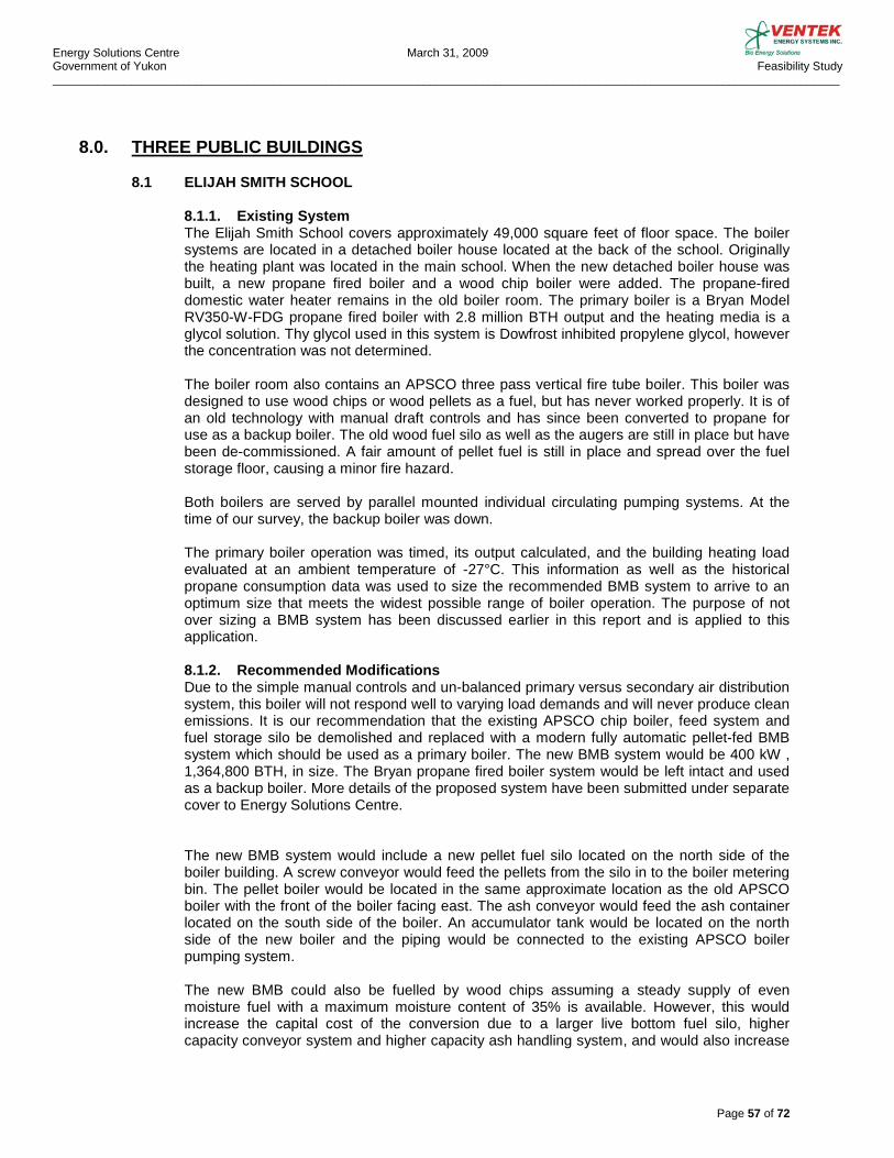
Energy Solutions Centre March 31, 2009 Government of Yukon Feasibility Study _________________________________________________________________________________________________________________________
Page 57 of 72
8.0. THREE PUBLIC BUILDINGS
8.1 ELIJAH SMITH SCHOOL
8.1.1. Existing System The Elijah Smith School covers approximately 49,000 square feet of floor space. The boiler systems are located in a detached boiler house located at the back of the school. Originally the heating plant was located in the main school. When the new detached boiler house was built, a new propane fired boiler and a wood chip boiler were added. The propane-fired domestic water heater remains in the old boiler room. The primary boiler is a Bryan Model RV350-W-FDG propane fired boiler with 2.8 million BTH output and the heating media is a glycol solution. Thy glycol used in this system is Dowfrost inhibited propylene glycol, however the concentration was not determined. The boiler room also contains an APSCO three pass vertical fire tube boiler. This boiler was designed to use wood chips or wood pellets as a fuel, but has never worked properly. It is of an old technology with manual draft controls and has since been converted to propane for use as a backup boiler. The old wood fuel silo as well as the augers are still in place but have been de-commissioned. A fair amount of pellet fuel is still in place and spread over the fuel storage floor, causing a minor fire hazard. Both boilers are served by parallel mounted individual circulating pumping systems. At the time of our survey, the backup boiler was down. The primary boiler operation was timed, its output calculated, and the building heating load evaluated at an ambient temperature of -27°C. This information as well as the historical propane consumption data was used to size the recommended BMB system to arrive to an optimum size that meets the widest possible range of boiler operation. The purpose of not over sizing a BMB system has been discussed earlier in this report and is applied to this application. 8.1.2. Recommended Modifications Due to the simple manual controls and un-balanced primary versus secondary air distribution system, this boiler will not respond well to varying load demands and will never produce clean emissions. It is our recommendation that the existing APSCO chip boiler, feed system and fuel storage silo be demolished and replaced with a modern fully automatic pellet-fed BMB system which should be used as a primary boiler. The new BMB system would be 400 kW , 1,364,800 BTH, in size. The Bryan propane fired boiler system would be left intact and used as a backup boiler. More details of the proposed system have been submitted under separate cover to Energy Solutions Centre. The new BMB system would include a new pellet fuel silo located on the north side of the boiler building. A screw conveyor would feed the pellets from the silo in to the boiler metering bin. The pellet boiler would be located in the same approximate location as the old APSCO boiler with the front of the boiler facing east. The ash conveyor would feed the ash container located on the south side of the boiler. An accumulator tank would be located on the north side of the new boiler and the piping would be connected to the existing APSCO boiler pumping system. The new BMB could also be fuelled by wood chips assuming a steady supply of even moisture fuel with a maximum moisture content of 35% is available. However, this would increase the capital cost of the conversion due to a larger live bottom fuel silo, higher capacity conveyor system and higher capacity ash handling system, and would also increase

Energy Solutions Centre March 31, 2009 Government of Yukon Feasibility Study _________________________________________________________________________________________________________________________
Page 58 of 72
the boiler operating cost due to more frequent maintenance requirements. Also, assuming the same volumetric delivery truck for both pellets and chips, the truck traffic would increase from an estimated 4 trucks per year for pellets to 17 trucks per year for chips, thus increasing the overall carbon footprint. The building heating control system would be interfaced with the new BMB system controls. For further details see conceptual drawing ESW-109-SK1 Rev.0.
8.2 HIDDEN VALLEY SCHOOL 8.2.1. Existing System The Hidden Valley School is approximately 28,600 square feet in size. It is served by three propane-fired Burnham Model 808B-WPH gas boilers that provide heat to the in-floor heating system and the building Make-Up Air Unit heating coil. Each boiler has an output of 332,640 BTH for the total of 997,920 BTH. The heating media is a glycol solution. An Engineered Air in-direct propane-fired Make-up Air Unit provides heating and ventilation to the gymnasium. The unit delivers 9,000 cfm with a maximum output of 304,000 BTH. The domestic hot water is provided from an independent 250,000 BTH propane-fired domestic hot water heater. The boiler system operation was timed, its output calculated, and the building heating load evaluated at an ambient temperature of -30°C. This load calculation, the gymnasium Make-up Air Unit information as well as the historical propane consumption data was used to size the recommended BMB system to arrive to an optimum size that meets the widest possible range of boiler operating conditions. The purpose of not over sizing a BMB system has been discussed earlier in this report and is applied to this application as well. The domestic hot water demand is not included in our load calculations and is considered a minor load in the system. It is un-economical at this time to consider the domestic water be converted for use with the BMB system 8.2.2. Recommended Modifications A new 300 kW, 1,023,600 BTH, BMB boiler system should be installed and used as a primary heat source to this building. The gymnasium Make-up Air Unit should be converted from propane-fired to hot water and tied-in to the new system. This would allow for maximum use, fuel savings and benefit from the BMB system. The existing Burnham propane fired boilers would be left as backups and the control system programmed to allow staging of the three boilers as demanded by the heating load. More details of the proposed system have been submitted under separate cover to Energy Solutions Centre. The new pellet fired BMB system would be installed in a new boiler house located on the north side of the school building. A new pellet fuel silo would be placed adjacent to the new boiler house and a screw conveyor would feed the pellets from the silo in to the boiler metering bin. The ash conveyor, ash container, accumulator tank and other boiler accessories would all be mounted inside the new boiler room. Underground piping would connect the new BMB system to the existing heating system. The tie-in would be located inside the existing boiler room on the second floor of the school building. The building heating control system would be interfaced with the new BMB system controls. For further details see conceptual drawing HVW-109-SK1 Rev.0.
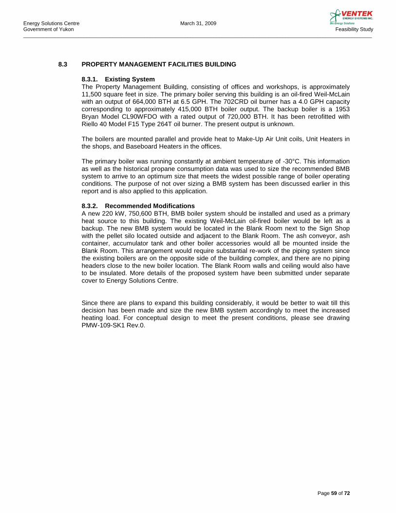
Energy Solutions Centre March 31, 2009 Government of Yukon Feasibility Study _________________________________________________________________________________________________________________________
Page 59 of 72
8.3 PROPERTY MANAGEMENT FACILITIES BUILDING 8.3.1. Existing System The Property Management Building, consisting of offices and workshops, is approximately 11,500 square feet in size. The primary boiler serving this building is an oil-fired Weil-McLain with an output of 664,000 BTH at 6.5 GPH. The 702CRD oil burner has a 4.0 GPH capacity corresponding to approximately 415,000 BTH boiler output. The backup boiler is a 1953 Bryan Model CL90WFDO with a rated output of 720,000 BTH. It has been retrofitted with Riello 40 Model F15 Type 264T oil burner. The present output is unknown. The boilers are mounted parallel and provide heat to Make-Up Air Unit coils, Unit Heaters in the shops, and Baseboard Heaters in the offices. The primary boiler was running constantly at ambient temperature of -30°C. This information as well as the historical propane consumption data was used to size the recommended BMB system to arrive to an optimum size that meets the widest possible range of boiler operating conditions. The purpose of not over sizing a BMB system has been discussed earlier in this report and is also applied to this application. 8.3.2. Recommended Modifications A new 220 kW, 750,600 BTH, BMB boiler system should be installed and used as a primary heat source to this building. The existing Weil-McLain oil-fired boiler would be left as a backup. The new BMB system would be located in the Blank Room next to the Sign Shop with the pellet silo located outside and adjacent to the Blank Room. The ash conveyor, ash container, accumulator tank and other boiler accessories would all be mounted inside the Blank Room. This arrangement would require substantial re-work of the piping system since the existing boilers are on the opposite side of the building complex, and there are no piping headers close to the new boiler location. The Blank Room walls and ceiling would also have to be insulated. More details of the proposed system have been submitted under separate cover to Energy Solutions Centre. Since there are plans to expand this building considerably, it would be better to wait till this decision has been made and size the new BMB system accordingly to meet the increased heating load. For conceptual design to meet the present conditions, please see drawing PMW-109-SK1 Rev.0.

Energy Solutions Centre March 31, 2009 Government of Yukon Feasibility Study _________________________________________________________________________________________________________________________
Page 60 of 72
9.0. CONCLUSIONS
The three buildings covered by our study all lend themselves to a BMB system conversion. However, since there are plans to expand the Property Management building, it may not be an appropriate time to do the conversion of this building before the final plans are in place. We have sized the Property Management building BMB system to meet with the present heating requirements and this design will obviously have to be revised if the building is expanded. Of the three buildings, the Elijah Smith School is a prime example of an ideal conversion project. All required infrastructure is in place and the installation and tie-in to the existing heating system can be done without disturbing the school operations. This conversion would be the first pilot project to be recommended. The Hidden Valley School, while requiring more infrastructure spending such as the new boiler house, is a good candidate for a BMB conversion. The original school drawings show a future expansion and this should be taken into account when sizing the BMB system supposing that there is a real possibility of the expansion project to proceed. This conversion would be the second pilot project to be recommended. We have attached conceptual drawings for all three buildings showing the recommended systems, system sizes, equipment, piping etc. Please refer to drawings ESW-109-SK1 Rev.0, HVW-109-SK1 Rev.0 and PMW-109-SK1 Rev.0 for more details. Also, as stated earlier in this report, detailed budget pricing for all three projects have been submitted to Energy Solutions Centre in separate submittals.
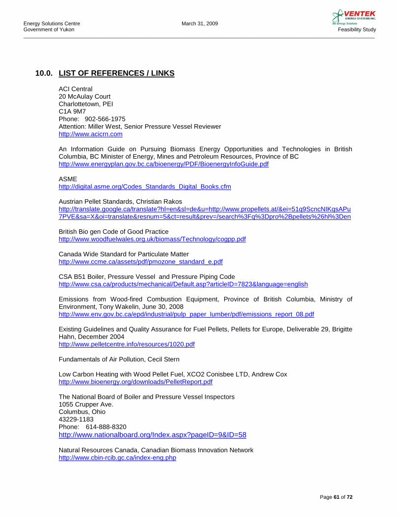
Energy Solutions Centre March 31, 2009 Government of Yukon Feasibility Study _________________________________________________________________________________________________________________________
Page 61 of 72
10.0. LIST OF REFERENCES / LINKS
ACI Central 20 McAulay Court Charlottetown, PEI C1A 9M7 Phone: 902-566-1975 Attention: Miller West, Senior Pressure Vessel Reviewer http://www.acicrn.com An Information Guide on Pursuing Biomass Energy Opportunities and Technologies in British Columbia, BC Minister of Energy, Mines and Petroleum Resources, Province of BC http://www.energyplan.gov.bc.ca/bioenergy/PDF/BioenergyInfoGuide.pdf ASME http://digital.asme.org/Codes_Standards_Digital_Books.cfm Austrian Pellet Standards, Christian Rakos http://translate.google.ca/translate?hl=en&sl=de&u=http://www.propellets.at/&ei=51q9ScncNIKqsAPu7PVE&sa=X&oi=translate&resnum=5&ct=result&prev=/search%3Fq%3Dpro%2Bpellets%26hl%3Den British Bio gen Code of Good Practice http://www.woodfuelwales.org.uk/biomass/Technology/cogpp.pdf Canada Wide Standard for Particulate Matter http://www.ccme.ca/assets/pdf/pmozone_standard_e.pdf CSA B51 Boiler, Pressure Vessel and Pressure Piping Code http://www.csa.ca/products/mechanical/Default.asp?articleID=7823&language=english Emissions from Wood-fired Combustion Equipment, Province of British Columbia, Ministry of Environment, Tony Wakelin, June 30, 2008 http://www.env.gov.bc.ca/epd/industrial/pulp_paper_lumber/pdf/emissions_report_08.pdf Existing Guidelines and Quality Assurance for Fuel Pellets, Pellets for Europe, Deliverable 29, Brigitte Hahn, December 2004 http://www.pelletcentre.info/resources/1020.pdf
Fundamentals of Air Pollution, Cecil Stern Low Carbon Heating with Wood Pellet Fuel, XCO2 Conisbee LTD, Andrew Cox http://www.bioenergy.org/downloads/PelletReport.pdf The National Board of Boiler and Pressure Vessel Inspectors 1055 Crupper Ave. Columbus, Ohio 43229-1183 Phone: 614-888-8320 http://www.nationalboard.org/Index.aspx?pageID=9&ID=58 Natural Resources Canada, Canadian Biomass Innovation Network http://www.cbin-rcib.gc.ca/index-eng.php
Energy Solutions Centre March 31, 2009 Government of Yukon Feasibility Study _________________________________________________________________________________________________________________________
Page 62 of 72
Ordering and Receiving Wood Chips, Pieter D. Kofman, http://www.woodenergy.ie/iopen24/pub/ccnorderingchips.pdf Petroleum Marketing Monthly http://www.eia.doe.gov/oil_gas/petroleum/data_publications/petroleum_marketing_monthly/pmm.html
Wood Fuels, Characteristics, standards, Production Technology, Kasimir P. Nemestothy, Austrian Energy Agency http://www.bioheat.info/pdf/kpn_wood_fuels_at.pdf Wood Pellet Association of Canada http://www.pellet.org/Site/Forms/ViewPage.aspx?PageID=216 Upgraded Biofuels Effects of Quality on Processing, Handling, characteristics, Combustion and Ash Melting, Susanne Paulrud, unit of Biomass Technology and Chemistry, Swedish University of Agricultural Sciences, 2004 http://diss-epsilon.slu.se/archive/00000533/01/Agraria449.pdf US Government Energy Information Administration http://www.eia.doe.gov/oiaf/forecasting.html
11.0. DISCLAIMER This report has been prepared for use by the Government of Yukon. All data used for this report is as up-to-date as was available at the time of the writing of this report. The authors take no responsibility of any errors or interpretations when such data is used by a third party. Any use that a third party makes of this Report or reliance thereon, or any decisions to be made based on it, is the responsibility of such third party. Ventek Energy Systems Inc. and the authors accept no responsibility for damages, if any, suffered by any third party as a result of decisions made or action taken based on this Report.
Energy Solutions Centre March 31, 2009 Government of Yukon Feasibility Study _________________________________________________________________________________________________________________________
Page 63 of 72
12.0. APPENDIX
APPENDIX A Notes and Calculations for Section 7.1.5 Fuel Cost Analysis Graphs and LCA Spread Sheet Fossil Fuels: Figure 7.1.5.A Elijah Smith Figure 7.1.5.B Hidden Valley School Figure 7.1.5.C Property Management Facilities Building These graphs summarize the information from the Energy Life Cycle Analysis Chart relating to the number of years required to pay back the initial investment based on varying fossil fuel costs. Given Values: Delivered Cost of pellets quoted as per report @ $ 235.00 per Tonne Delivered Cost of Propane per Litre $0.60 Delivered Cos of Fuel Oil per Litre $0.864 Propane net heating value 22,310 Btu/L Propane liquid density 0.509 kg/L Weight of CO2 in combustion products, propane 3.01 kg/kg #2 Heating oil net heating value 129,000 Btu/gal #2 Heating oil density 0.865 kg/L Weight of CO2 in combustion products, #2 Heating Oil 3.2 kg/kg Assumed Values: Pellets @ 5 % moisture content and 18 GJ/T Fuel Escalation rates in % based on US Gov’t Energy Information Administration No values for amortization or maintenance cost are presented Inflation included in fuel escalation rates Calculations: EPC = Equivalent Pellet Consumption per litre of a given fossil fuel, expressed in Tonnes of pellets. EPC for Propane: 1 L x 22310 Btu/L x 1.055 kJ --------------------------------------- = 0.0013 Tonnes 18 x 106 kJ/Tonne EPC for Oil: 1 L x 129000 Btu/gal x 1.055 kJ ------------------------------------------- = 0.0020 Tonnes 3.78 L x 18 x 106 kJ/Tonne
Energy Solutions Centre March 31, 2009 Government of Yukon Feasibility Study _________________________________________________________________________________________________________________________
Page 64 of 72
Figure 7.1.5.E Cumulative Savings and 7.1.5.F Total Fuel Dollars – 20 Years These graphs depict the totals form the Energy Life Cycle Analysis sheet. Savings and fuel dollars spent. No allowance or interpretation is presented for maintenance costs, amortization or inflation. Figure 7.1.5.G Tonnes of C02 – 20 Year Period The following calculations were used in the presentation of this graph: Total average annual propane fuel consumption for Elijah Smith School 132,575 L CO2 release: 0.509 kg/L x 3.01 kg/kg x 132575 L x 20 yrs = 4,062,300 kg = 4,060 Tonnes Total average annual propane fuel consumption Hidden Value School 73,760 L CO2 release: 0.509 kg/L x 3.01 kg/kg x 73,760 L x 20 yrs = 2,260,100 kg = 2,260 Tonnes Total average annual fuel oil consumption for Property Management Bldg. 35,790 L CO2 release: 0.865 kg/L x 3.2 kg/kg x 35790 L x 20 yrs = 1,981,300 kg = 1,980 Tonnes Calculations regarding removal of 150 mid size vehicles for a 20 year period: Average annual kilometers driven 20,000 km Average fuel consumption 6 L/100 km Gasoline density 0.733 kg/L Weight of CO2 in combustion products, gasoline 3.14 kg/kg Total CO2 released from the three building’s heating system during a 20 year period = 4,060 + 2,260 + 1,980 Tonnes = 8,300 Tonnes Total CO2 released from a mid size car during a 20 year period = 20,000 km/yr x 6 L x 0.733 kg/L x 3.14 kg/kg x 20 yr ---------------------------------------------------------------------- = 55,240 kg = 55.24 Tonnes 100 km
8,300 Tonnes ------------------------ = 150 cars 55.24 Tonnes/car References: North American Combustion Handbook, Second Edition 1978
Energy Solutions Centre March 31, 2009 Government of Yukon Feasibility Study _________________________________________________________________________________________________________________________
Page 65 of 72
APPENDIX B Notes for the Net Present Value (NPV) calculations The annual fuel cost is based on the actual average annual energy consumption for each school. The cost of fuel is based on the actual fuel cost per unit for year 2008. For project evaluation purposes it is assumed that Elijah Smith School would require an installation of a new back-up propane boiler immediately, and that Hidden Valley School propane boilers would be replaced after another ten years of operation. The below mentioned 2% interest rate is used to escalate the price of Hidden Valley School propane boiler replacement cost over 10 years. Time value of money: Present average bank rate was researched to be 1.946%. A rate of 2.0% is used in our evaluation (shown as “Disc.%) The following annual escalation rates were used in our evaluation: - Wood Pellets 2.23% - Propane 2.7% (Chart 3 and Chart 6 calculations use 5.0% escalation for propane) - Maintenance Cost 3.0%
Our program does not allow insertion of negative numbers to indicate cash outflow. The values in column “Total NPV” are all cash outflow numbers and, as such, should be viewed as negative values. In other words, the smaller the number as shown is, the more attractive the NPV value is, and the less value the investment would subtract from the operation. The charts show cash outflows up to 25 years to the future. Yukon Government requested 20 year evaluation which corresponds to the numbers shown below. In summary, the following are the 20 year NPV (cash outflow) values for the subject projects: Elijah Smith School, Bioboiler System Chart 1 = ($980,924.00) Elijah Smith School, Propane Boiler System Chart 2 = ($1,864,449.00) Elijah Smith School, Propane Boiler System Chart 3 = ($2,284,435.00) Hidden Valley School, Bioboiler System Chart 4 = ($852,416.00) Hidden Valley School, Propane Boiler System Chart 5 = ($1,106,758.00) Hidden Valley School, Propane Boiler System Chart 6 = ($1,339,430.00)

Energy Solutions Centre March 31, 2009 Government of Yukon Feasibility Study _________________________________________________________________________________________________________________________
Page 66 of 72
Project Payback The Bioboiler payback was manually interpolated as follows: Elijah Smith School: Total Bioboiler project budget cost of $515,000.00 was compared against annual escalated cost of the Propane Boiler system, shown in column “Total NPV” of Charts 2 and 3. Interpolating from Chart 2 “Total NPV” column Elijah Smith payback is 4.4 years with propane price increase of 2.7%/yr and from Chart 3 “Total NPV” column 4.2 years with propane price increase of 5.0%/yr. Hidden Valley School: Total Bioboiler project budget cost of $565,000.00 was compared against annual escalated cost of the Propane Boiler system, shown in column “Total NPV” of Charts 5 and 6. Interpolating from Chart 5 “Total NPV” column Hidden Valley payback is 9.8 years with propane price increase of 2.7%/yr and from Chart 6 “Total NPV” column 9.5 years with propane price increase of 5.0%/yr.
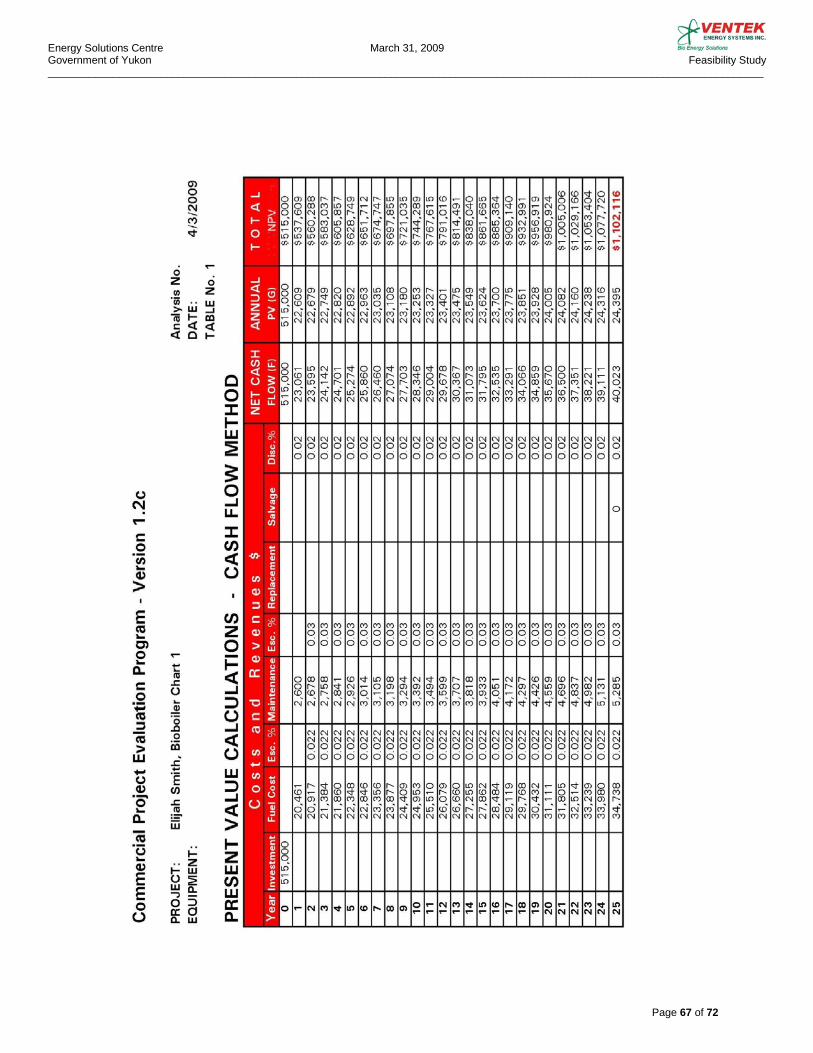
Energy Solutions Centre March 31, 2009 Government of Yukon Feasibility Study _________________________________________________________________________________________________________________________
Page 67 of 72

Energy Solutions Centre March 31, 2009 Government of Yukon Feasibility Study _________________________________________________________________________________________________________________________
Page 68 of 72
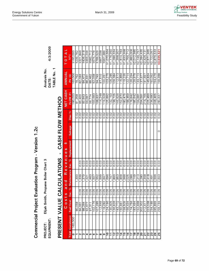
Energy Solutions Centre March 31, 2009 Government of Yukon Feasibility Study _________________________________________________________________________________________________________________________
Page 69 of 72
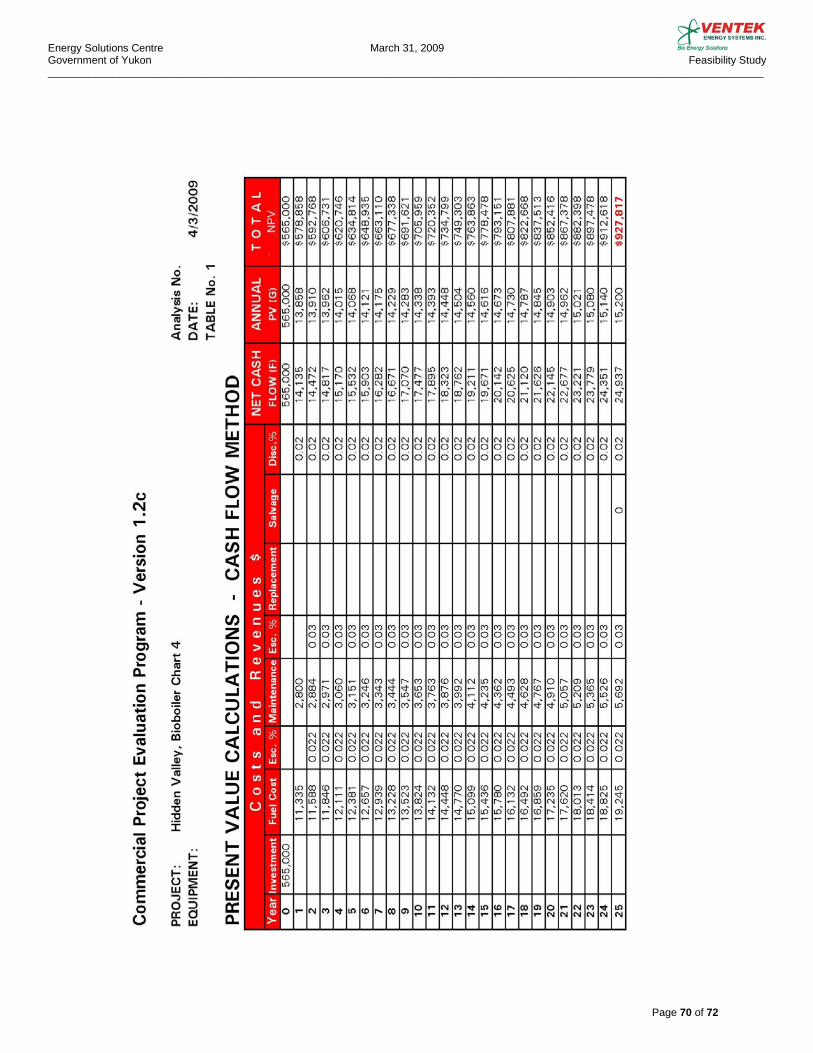
Energy Solutions Centre March 31, 2009 Government of Yukon Feasibility Study _________________________________________________________________________________________________________________________
Page 70 of 72

Energy Solutions Centre March 31, 2009 Government of Yukon Feasibility Study _________________________________________________________________________________________________________________________
Page 71 of 72

Energy Solutions Centre March 31, 2009 Government of Yukon Feasibility Study _________________________________________________________________________________________________________________________
Page 72 of 72