Embed Size (px)
Citation preview
1
FEASIBILITY REPORT
ON
ESTABLISHMENT OF LOCAL MANUFACTURE FACILITY AND TRANSFER OF TECHNOLOGY
FOR SMALL HYDRO POWER TURBINES IN
WEST AFRICA
By
UNIDO REGIONAL CENTRE FOR SMALL HYDRO POWER in AFRICA ABUJA, NIGERIA.
2
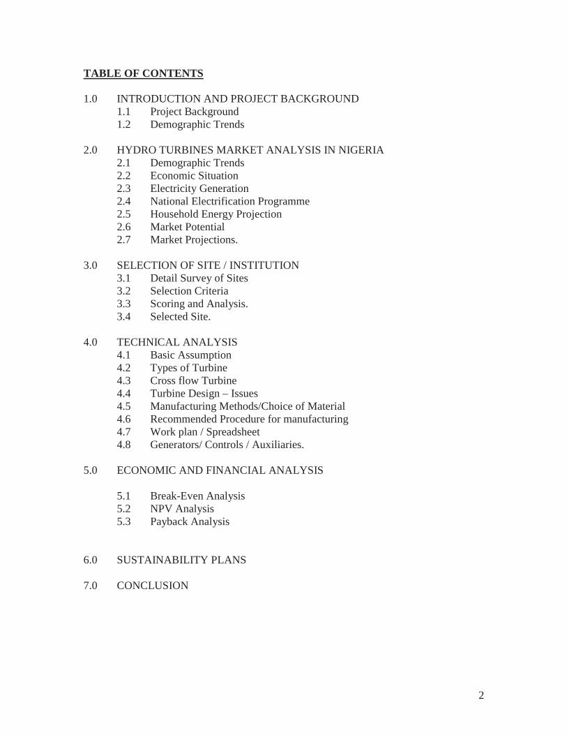
TABLE OF CONTENTS
1.0 INTRODUCTION AND PROJECT BACKGROUND 1.1 Project Background 1.2 Demographic Trends
2.0 HYDRO TURBINES MARKET ANALYSIS IN NIGERIA 2.1 Demographic Trends 2.2 Economic Situation 2.3 Electricity Generation 2.4 National Electrification Programme 2.5 Household Energy Projection 2.6 Market Potential 2.7 Market Projections.
3.0 SELECTION OF SITE / INSTITUTION 3.1 Detail Survey of Sites 3.2 Selection Criteria 3.3 Scoring and Analysis. 3.4 Selected Site.
4.0 TECHNICAL ANALYSIS 4.1 Basic Assumption 4.2 Types of Turbine 4.3 Cross flow Turbine 4.4 Turbine Design – Issues 4.5 Manufacturing Methods/Choice of Material 4.6 Recommended Procedure for manufacturing 4.7 Work plan / Spreadsheet 4.8 Generators/ Controls / Auxiliaries.
5.0 ECONOMIC AND FINANCIAL ANALYSIS
5.1 Break-Even Analysis 5.2 NPV Analysis
5.3 Payback Analysis
6.0 SUSTAINABILITY PLANS
7.0 CONCLUSION
3
LIST OF FIGURES Figure 1 - Map of Africa.
Figure 2. - Map of Nigeria
Figure 3. - Map of Enugu and Ondo States
Figure 4. - Nigeria River System and Basins
4
LIST OF TABLES
Table 1 - Electricity Installation Generation Capacity in Africa (1997)
Table 2.0 – Percentage of Households by Type of Electricity Supply.
Table 2.1 – Small Hydro Electricity Projection in Nigeria.
Table 2.2 - Investigated Potential Sites in Nigeria
Table 2.3 - Estimated Nigeria Small Hydro Power Demand
Table 3.1 – Scoring of Surveyed Institutes
Table 4.1 - Small Turbine Classification
Table 4.2 - Projected Manufacturing Cost Estimate and Duration.
Table 5.1 - Break-Even Analysis
Table 5.2 - NPV Analysis Table 5.3 - Payback Analysis

5
LIST OF ABBREVIATIONS
S/N Abbreviations Meanings
1. ECN Energy Commission of Nigeria
2. NDA Niger Dams Authority
3. NEPA National Electricity Power Authority
4. PHCN Power Holding Company of Nigeria
5. FGN Federal Government of Nigeria
6. UNIDO United Nation Industrial Development Organization
7. R & D Research and Development
8. SHP Small Hydro Power
9. ECOWAS Economic Commission of West African States
10. DOE Department of Energy
11. FEMA Forum of Energy Minister’s in Africa
12. NEPAD New Partnership for African Development.
13. REA Rural Electrification Agency
14. MDG Millennium Development Goal
15. UNDP United Nations Development Programme
16. GEF Global Environmental Fund
17. GHG Green House Gases
18. RETs Renewable Energy Technologies
19. W.A West Africa
20. PRODA Project Development Agency
21. NASENI National Agency for Science and Engineering Infrastructure.

6
1.0 INTRODUCTION / BACKGROUND.
7-Point Agenda of the Federal Government of Nigeria high points are wealth creation, improved lifestyles of the populace and improved national economy. Human Capacity Development and provision of Critical Infrastructure have been identified as the linchpins for actualizing these goals. For sustainable wealth creation to be achieved and for Nigeria to be among the top 20 economies in the world by 2020, the nation must cease to be a “dumping ground” for manufactured goods from all-over the world and join the rest of the advancing economies in the manufacture of goods for local consumption and export.
The development of cottage, small and medium industries and the manufacture of quality products at competitive prices depend on constant supply of reliable electricity and the utilization of Advanced Manufacturing Technology.
More than 60% of communities in Nigeria are still not connected to the National Grid. The cost of extending the grid is currently high, compared with the cost of installing off-grid electricity generation plants. Absence of electricity in rural areas is an indication of poverty and lack of developed infrastructure. This has promoted urban migration in search of employment and improved standard of living due to the presence of large, medium, and small scale industries that are heavily dependent on electricity.
Nigeria is blessed with a vast amount of water resources from which electricity could be generated. With Small Hydro Power (SHP) plants, electricity can be generated even from small streams and rivers. SHP plants are easy to install and manage. When used for stand-alone, decentralized electricity supply, it does not require very high investments in transmission lines since the end-users are close to the source of generation of the electricity.
1.1 PROJECT BACKGROUND Nigeria is a coastline country in West Africa that got its independence in October 1960. The British Government built the first generating plant in Nigeria in Lagos in 1898. The generation, transmission Ordinance No 15 of 1959 vested distribution and marketing of electricity on the defunct Electricity Corporation of Nigeria (ECN). Later, the Niger Dams Authority was set up in 1962; in 1972 the Niger Dams Authority (NDA) and the ECN became merged by Decree No 24 of 27th June 1972 to give birth to the National Electricity Power Authority (NEPA). The Electricity Reforms Act of 2005 further gave birth to the Power Holding Company of Nigeria (PHCN), which is currently undergoing restructuring into business units as well as the National Electricity Regulating Commission (NERC).
More than 18 State Governments are already working towards the deployment of SHP for electricity generation in their states. In some states, the plan is to establish SHP plants in each of their Senatorial Districts and later to all their Local Government Areas. The Federal Government through its Rural Electricity Agency (REA) and Non-Governmental organisations are also working towards the deployment of SHP in selected sites all over the country.
7
Electricity generation in rural communities would increase and the need for productive use of the power generated (apart from lighting and domestic uses only) would also increase. The demand for the locally fabricated SHP turbine would increase. All these would result to an increase in the demand for skilled personnel in these areas.
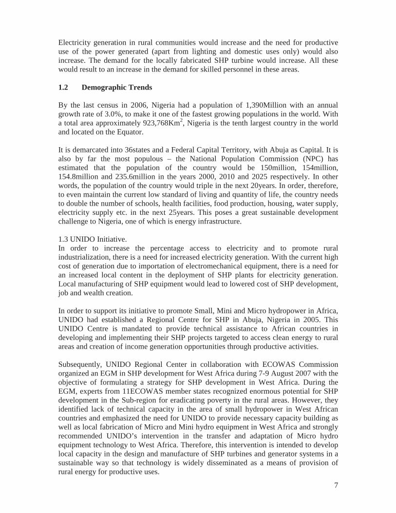
1.2 Demographic Trends
By the last census in 2006, Nigeria had a population of 1,390Million with an annual growth rate of 3.0%, to make it one of the fastest growing populations in the world. With a total area approximately 923,768Km2, Nigeria is the tenth largest country in the world and located on the Equator.
It is demarcated into 36states and a Federal Capital Territory, with Abuja as Capital. It is also by far the most populous – the National Population Commission (NPC) has estimated that the population of the country would be 150million, 154million, 154.8million and 235.6million in the years 2000, 2010 and 2025 respectively. In other words, the population of the country would triple in the next 20years. In order, therefore, to even maintain the current low standard of living and quantity of life, the country needs to double the number of schools, health facilities, food production, housing, water supply, electricity supply etc. in the next 25years. This poses a great sustainable development challenge to Nigeria, one of which is energy infrastructure.
1.3 UNIDO Initiative. In order to increase the percentage access to electricity and to promote rural industrialization, there is a need for increased electricity generation. With the current high cost of generation due to importation of electromechanical equipment, there is a need for an increased local content in the deployment of SHP plants for electricity generation. Local manufacturing of SHP equipment would lead to lowered cost of SHP development, job and wealth creation.
In order to support its initiative to promote Small, Mini and Micro hydropower in Africa, UNIDO had established a Regional Centre for SHP in Abuja, Nigeria in 2005. This UNIDO Centre is mandated to provide technical assistance to African countries in developing and implementing their SHP projects targeted to access clean energy to rural areas and creation of income generation opportunities through productive activities.
Subsequently, UNIDO Regional Center in collaboration with ECOWAS Commission organized an EGM in SHP development for West Africa during 7-9 August 2007 with the objective of formulating a strategy for SHP development in West Africa. During the EGM, experts from 11ECOWAS member states recognized enormous potential for SHP development in the Sub-region for eradicating poverty in the rural areas. However, they identified lack of technical capacity in the area of small hydropower in West African countries and emphasized the need for UNIDO to provide necessary capacity building as well as local fabrication of Micro and Mini hydro equipment in West Africa and strongly recommended UNIDO’s intervention in the transfer and adaptation of Micro hydro equipment technology to West Africa. Therefore, this intervention is intended to develop local capacity in the design and manufacture of SHP turbines and generator systems in a sustainable way so that technology is widely disseminated as a means of provision of rural energy for productive uses.
8
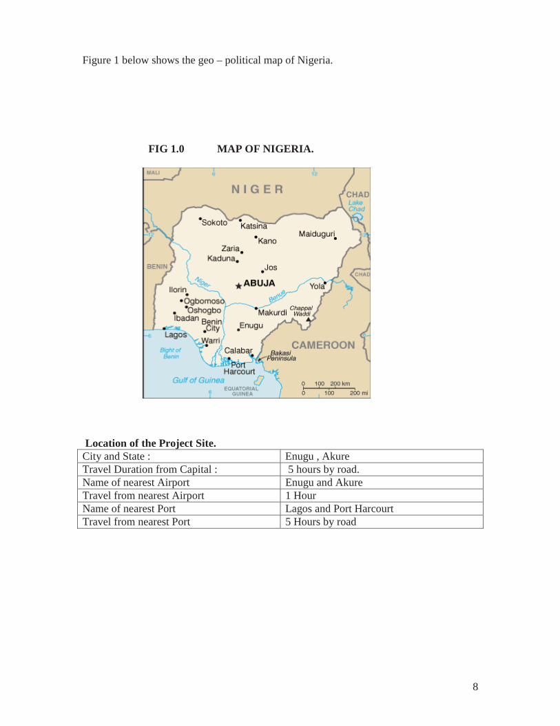
Figure 1 below shows the geo – political map of Nigeria.
FIG 1.0 MAP OF NIGERIA.
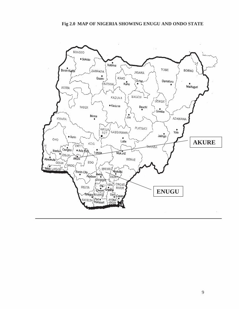
Location of the Project Site. City and State : Enugu , Akure Travel Duration from Capital : 5 hours by road. Name of nearest Airport Enugu and Akure Travel from nearest Airport 1 Hour Name of nearest Port Lagos and Port Harcourt Travel from nearest Port 5 Hours by road
9
Fig 2.0 MAP OF NIGERIA SHOWING ENUGU AND ONDO STATE
ENUGU
AKURE
10
2.0 HYDRO TURBINES MARKET ANALYSIS IN NIGERIA
2.1 Economic Situation.
Nigeria is richly endowed with both human and natural resources. The economy depended for a long time, to a large extent on oil revenue, which accounted for 90% of foreign exchange earnings in 2002. However, agriculture remains the main stay of the economy as it accounts for 40% of GDP, employs over 70% of the workforce and provides 90% of the non – oil export earning (2)
Recent CBN reports show that economic growth in Nigeria, which averagely is below 3% per annum from 1996 to 1999, took an upward turn between 2000 and 2001. Growth increased from 2.8% in 1999 to 4.2% in 2001 and declined to 3.3% in 2002. However, since population growth averaged 3% per annum over the period, this improvement in GDP growth made little impact on the standard of living in the country.
Poverty in Nigeria is associated with high unemployment, poor governance, corruption, lack of accountability, gross violation of human rights, nepotism and a skewed income distribution; additional factors include poor infrastructure and impaired access to productive and financial assets by women and vulnerable groups. Poverty has a gender dimension as women are overrepresented among the poor due to subordinate status of women, traditional and socio-cultural practices, discrimination and lack of access to assets and financial services. The incidence of poverty has increased over time. Available data from the Federal office of statistics indicate that although the incidence of poverty declined between 1985 and 1992 but since then, it has been on the rise. By 1996 it was estimated that approximately 65.6% Nigerians (67.1million people) lived below the poverty line. Poverty was more pronounced in rural than urban areas with poverty rates of 69.8% and 55.2% respectively.
Poverty incidence in the country for 1980, 1985, 1992, were 28.1, 42.1, 46.3 and 65.5 percent respectively. A common feature of poverty in Nigeria is that it is largely Rural based. However, there is an increasing evidence of pauperization of the urban areas, for instance, while the number of the poor in rural areas fell sharply from 26.3million between 1985 and 1992, those in urban areas rose from 9.7million to 11.9million in the same interval.
2.2 Electricity Generation.
It is estimated that, on the average, consumers are cut off from grid electricity for 10hours everyday. This has compelled many consumers (mostly industrial) to procure electricity generating sets for private use. The high cost of spare parts and fuel for running these generators make it uneconomical and inconvenient for use. The distribution of households in the country by types of electricity supply is presented in Table 2.2, which shows that about 80% of the rural populations have no electricity, which partly explains why the standard of living in the rural areas has remained low with poor economic growth.

11
Table 2.0: Percentage of Households by Type of Electricity Supply.
Type of Electricity Urban Semi - Urban Rural No Electricity 24.37 55.21 83.65PHCN Only 73.32 38.80 13.24Rural Electricity Only 1.85 5.99 2.81 Private Generator Only 0.23 0.00 0.29 PHCN/Rural Electricity 0.23 0.00 0.00
Rural Electricity generated by other organisation apart from PHCN
Electricity is an essential instrument for industrial, social, and economic development. With a very expansive landmass, the Power Holding Company of Nigeria has enormous task of extending the grid electricity to all the areas. At present, the country has only about 11,000 kilometers of Transmission lines. In view of the cost of equipment procurement, rehabilitation and repairs and the high running cost of diesel generators, there is need to consider other electricity generation resources as an alternative option, particularly for the rural areas.
2.3 Rural Electrification
The nationwide rural electrification programme aimed at connecting all Local Government Headquarters (LGHQ) and some other strategic and important towns and villages to the national grid is very crucial to the overall development of the country in general and particularly that of the rural areas. It is pertinent to note that of all the vital infrastructures necessary for the upliftment of our rural areas, the provision of electricity supply is undoubtedly the most important. Rural Electrification is, therefore, the key to the transformation of our rural areas from mere producers of farm products and fetchers of wood to an agro-based community with a standard of living rising above subsistence level. It is, therefore, obvious that the success of the nationwide rural electrification is crucial to the realization of the objectives of the nation’s development programmes. This is particularly true with the poverty Alleviation/Poverty Reduction Programme of the Federal Government. This statement underscores the reason why the present Administration has made nationwide rural electrification one of its cardinal objective programmes for implementation.
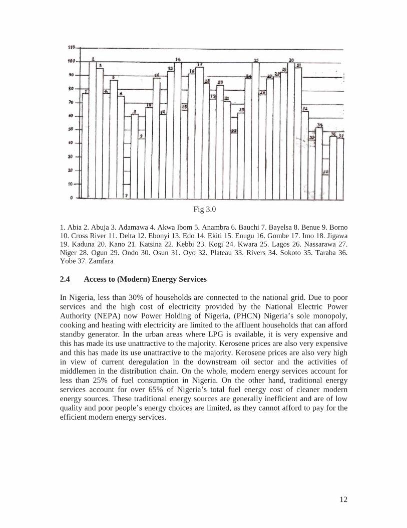
The National Electrification Programme implemented during the period 1989 – 1999 was able to complete 340 projects, while additional 110 projects were carried out from 1999 – 2006. Fig. 3.0 below shows the level of electrification in Nigeria.
12
Fig 3.0
1. Abia 2. Abuja 3. Adamawa 4. Akwa Ibom 5. Anambra 6. Bauchi 7. Bayelsa 8. Benue 9. Borno 10. Cross River 11. Delta 12. Ebonyi 13. Edo 14. Ekiti 15. Enugu 16. Gombe 17. Imo 18. Jigawa 19. Kaduna 20. Kano 21. Katsina 22. Kebbi 23. Kogi 24. Kwara 25. Lagos 26. Nassarawa 27. Niger 28. Ogun 29. Ondo 30. Osun 31. Oyo 32. Plateau 33. Rivers 34. Sokoto 35. Taraba 36. Yobe 37. Zamfara
2.4 Access to (Modern) Energy Services
In Nigeria, less than 30% of households are connected to the national grid. Due to poor services and the high cost of electricity provided by the National Electric Power Authority (NEPA) now Power Holding of Nigeria, (PHCN) Nigeria’s sole monopoly, cooking and heating with electricity are limited to the affluent households that can afford standby generator. In the urban areas where LPG is available, it is very expensive and this has made its use unattractive to the majority. Kerosene prices are also very expensive and this has made its use unattractive to the majority. Kerosene prices are also very high in view of current deregulation in the downstream oil sector and the activities of middlemen in the distribution chain. On the whole, modern energy services account for less than 25% of fuel consumption in Nigeria. On the other hand, traditional energy services account for over 65% of Nigeria’s total fuel energy cost of cleaner modern energy sources. These traditional energy sources are generally inefficient and are of low quality and poor people’s energy choices are limited, as they cannot afford to pay for the efficient modern energy services.
13
2.5 Market Potential
The major / key drivers for the Turbine market in Nigeria are population growth; government – sponsored programs such as NEEDS; MDG’s; Rural electrification; access to rural energy; high cost of fuel; O & M related expenses associated with diesel based generator sets together with the unreliability of fuel supply. These factors are currently prevalent in the Nigerian economy and are the basis for fuel interchange / alternative fuels such as the Small Hydropower that operates on hydro turbines.
2.5.1 Renewable Energy Programme
The energy policy for Nigeria launched in 2005 has further been followed with an Energy master plan. The Federal Govt of Nigeria has a 10yr target for the contribution of RETs to the economy – (2007 - 2017).
The target in MW based on peak demand from SHP are 40(2007); 100(2008) and 400(2016). Planned Small hydro electricity project are shown in Table 2.6 below.
14
Table 2.1: Small hydro Electricity Projection in Nigeria
No of System 2007 2008 2009 2010 2011 2012 2013 2014 2015 2016Cumulative No. of Systems. (Ave.nominal power =10MW) ,
Cum. power, MW
0 0 0 0
1 1 10 10
2 3 20 30
4 7 40 70
5 12 50 120
5 17 50 170
5 22 50 220
5 27 50 270
5 32 50 320
5 37 50 370
Sys cost A @ US$1500/Kw, $m Sys cost B @ US$2000/Kw, $m Sys cost C @ US$2500/Kw, $M
0
0
0
15
20
25
30
40
50
60
80
100
75
100
125
75
100
125
75
100
125
75
100
125
75
100
125
75
100
125
Sys cost A @N130/US$,bN Sys cost B @N130/US$,bN Sys cost C @N130/US$,bN
0
0
0
1.95
2.6
3.25
3.9
5.2
6.5
7.8
10.4
13
9.75
13
16.25
9.75
13
16.25
9.75
13
16.25
9.75
13
16.25
9.75
13
16.25
9.75
13
16.25
1000 Tons CO2 saved (If natural gas used)
0 13.14
26.28
52.56
65.7 65.7 65.7 65.7 65.7 65.7
1000 Tons CO2 saved (If fuel oil used)
0 19.053
38.106
76.212
95.265
95.265
95.265
95.265
95.265
95.265
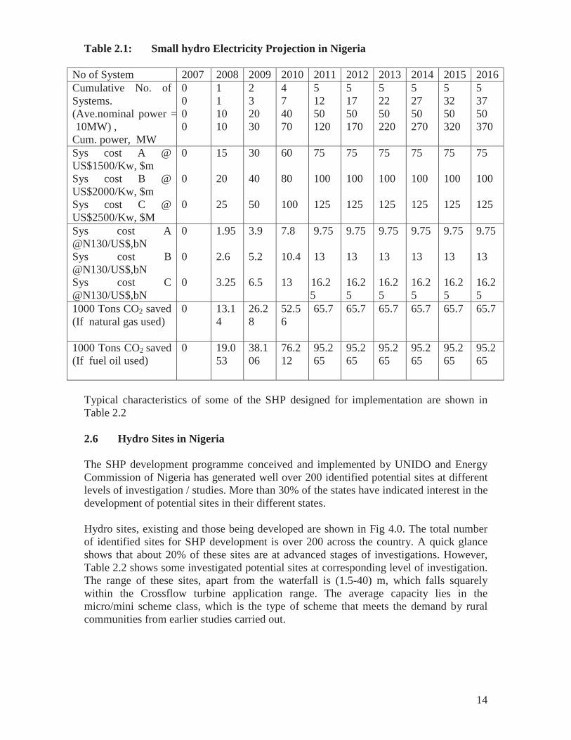
Typical characteristics of some of the SHP designed for implementation are shown in Table 2.2
2.6 Hydro Sites in Nigeria
The SHP development programme conceived and implemented by UNIDO and Energy Commission of Nigeria has generated well over 200 identified potential sites at different levels of investigation / studies. More than 30% of the states have indicated interest in the development of potential sites in their different states.
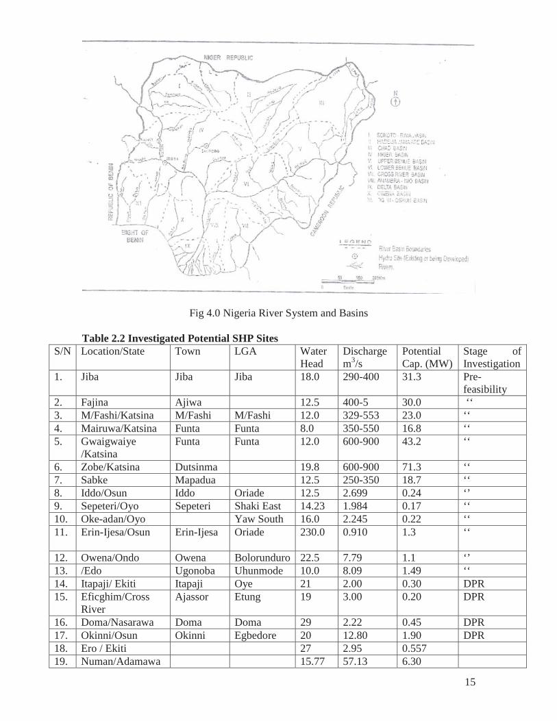
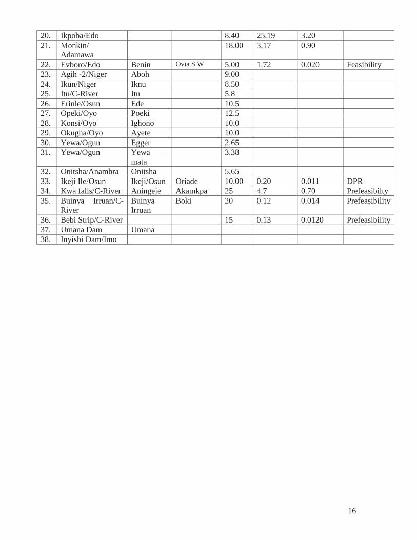
Hydro sites, existing and those being developed are shown in Fig 4.0. The total number of identified sites for SHP development is over 200 across the country. A quick glance shows that about 20% of these sites are at advanced stages of investigations. However, Table 2.2 shows some investigated potential sites at corresponding level of investigation. The range of these sites, apart from the waterfall is (1.5-40) m, which falls squarely within the Crossflow turbine application range. The average capacity lies in the micro/mini scheme class, which is the type of scheme that meets the demand by rural communities from earlier studies carried out.
15
Fig 4.0 Nigeria River System and Basins
Table 2.2 Investigated Potential SHP Sites S/N Location/State Town LGA Water
Head Discharge m3/s
Potential Cap. (MW)
Stage of Investigation
1. Jiba Jiba Jiba 18.0 290-400 31.3 Pre-feasibility
2. Fajina Ajiwa 12.5 400-5 30.0 ‘‘ 3. M/Fashi/Katsina M/Fashi M/Fashi 12.0 329-553 23.0 ‘‘ 4. Mairuwa/Katsina Funta Funta 8.0 350-550 16.8 ‘‘5. Gwaigwaiye
/Katsina Funta Funta 12.0 600-900 43.2 ‘‘
6. Zobe/Katsina Dutsinma 19.8 600-900 71.3 ‘‘ 7. Sabke Mapadua 12.5 250-350 18.7 ‘‘ 8. Iddo/Osun Iddo Oriade 12.5 2.699 0.24 ‘’ 9. Sepeteri/Oyo Sepeteri Shaki East 14.23 1.984 0.17 ‘‘ 10. Oke-adan/Oyo Yaw South 16.0 2.245 0.22 ‘‘ 11. Erin-Ijesa/Osun Erin-Ijesa Oriade 230.0 0.910 1.3 ‘‘
12. Owena/Ondo Owena Bolorunduro 22.5 7.79 1.1 ‘’ 13. /Edo Ugonoba Uhunmode 10.0 8.09 1.49 ‘‘ 14. Itapaji/ Ekiti Itapaji Oye 21 2.00 0.30 DPR 15. Eficghim/Cross
River Ajassor Etung 19 3.00 0.20 DPR
16. Doma/Nasarawa Doma Doma 29 2.22 0.45 DPR 17. Okinni/Osun Okinni Egbedore 20 12.80 1.90 DPR 18. Ero / Ekiti 27 2.95 0.557 19. Numan/Adamawa 15.77 57.13 6.30
16
20. Ikpoba/Edo 8.40 25.19 3.20 21. Monkin/
Adamawa 18.00 3.17 0.90
22. Evboro/Edo Benin Ovia S.W 5.00 1.72 0.020 Feasibility 23. Agih -2/Niger Aboh 9.00 24. Ikun/Niger Iknu 8.50 25. Itu/C-River Itu 5.8 26. Erinle/Osun Ede 10.5 27. Opeki/Oyo Poeki 12.5 28. Konsi/Oyo Ighono 10.0 29. Okugha/Oyo Ayete 10.0 30. Yewa/Ogun Egger 2.65 31. Yewa/Ogun Yewa –
mata 3.38
32. Onitsha/Anambra Onitsha 5.65 33. Ikeji Ile/Osun Ikeji/Osun Oriade 10.00 0.20 0.011 DPR 34. Kwa falls/C-River Aningeje Akamkpa 25 4.7 0.70 Prefeasibilty 35. Buinya Irruan/C-
River Buinya Irruan
Boki 20 0.12 0.014 Prefeasibility
36. Bebi Strip/C-River 15 0.13 0.0120 Prefeasibility37. Umana Dam Umana 38. Inyishi Dam/Imo
17
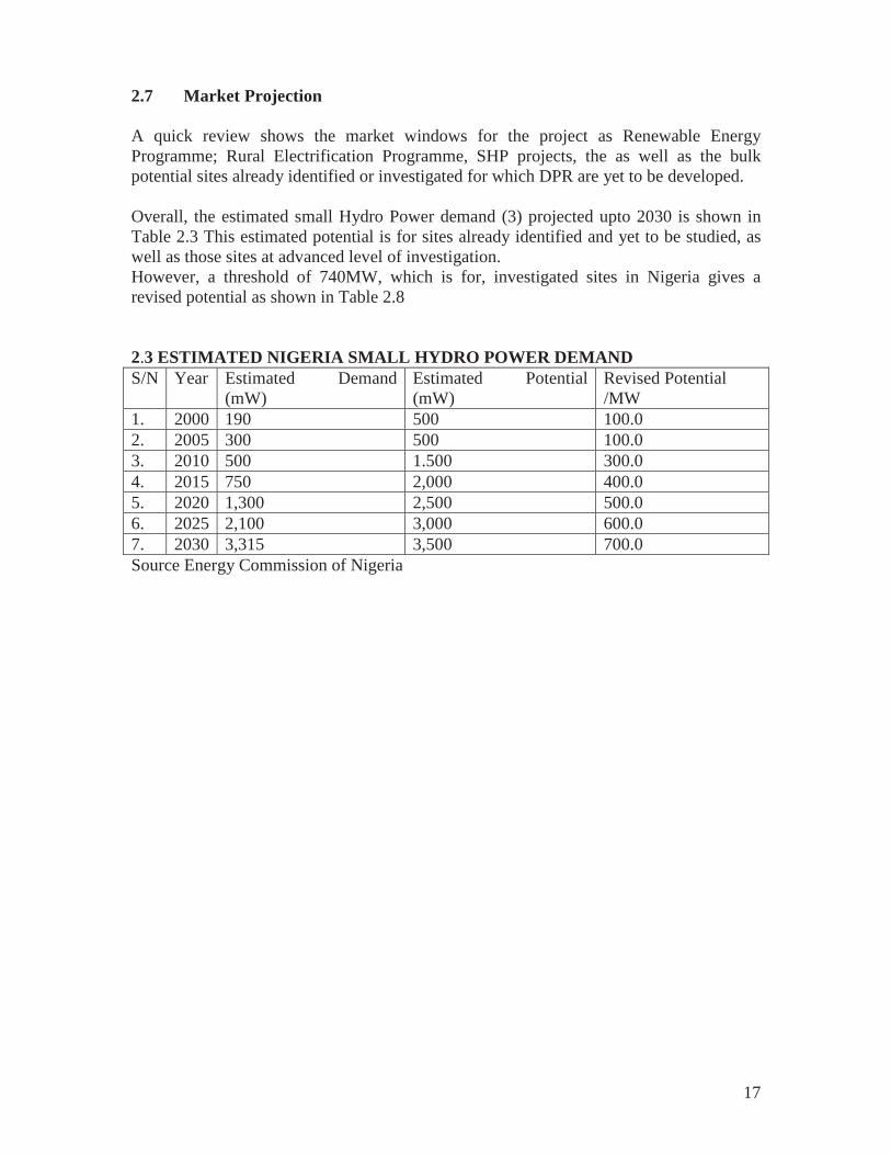
2.7 Market Projection
A quick review shows the market windows for the project as Renewable Energy Programme; Rural Electrification Programme, SHP projects, the as well as the bulk potential sites already identified or investigated for which DPR are yet to be developed.
Overall, the estimated small Hydro Power demand (3) projected upto 2030 is shown in Table 2.3 This estimated potential is for sites already identified and yet to be studied, as well as those sites at advanced level of investigation. However, a threshold of 740MW, which is for, investigated sites in Nigeria gives a revised potential as shown in Table 2.8
2.3 ESTIMATED NIGERIA SMALL HYDRO POWER DEMAND S/N Year Estimated Demand
(mW) Estimated Potential (mW)
Revised Potential /MW
1. 2000 190 500 100.0 2. 2005 300 500 100.0 3. 2010 500 1.500 300.0 4. 2015 750 2,000 400.0 5. 2020 1,300 2,500 500.0 6. 2025 2,100 3,000 600.0 7. 2030 3,315 3,500 700.0 Source Energy Commission of Nigeria

18
3.0 SELECTION OF SITE / INSTITUTION
The general features of an average Turbine consists essentially of four main components: the casing, the gate apparatus, the runner and the draft tube.
The production of these components simply involves the following mechanical activities: machining/assembly; working of spiral case, draft tube etc; Forging, Moulding and Casting. These activities require workshop facilities indicated in A-3.1
The equipment required for manufacturing these components, as well as the relevant tools are is shown in A- 3.2
It is obvious that in addition to the mechanical, the human resource (skills) as well its management is necessary in the manufacturing process. All these inputs contribute to, amongst others, the basic requirement for local manufacturing of the cross flow turbine.
It is equally important to state that the mechanical activities mentioned above are common to other useful items of the production and manufacturing sector of an economy. In the choice/selection of a site, it is necessary to carry out a survey of some identified R & D institution / organizations in the country.
3.1 Detailed Survey of Sites.
The following identified R&D institution or organization were visited one after the other, with a view of physically inspecting the facilities on ground; interact with the management and appraise the level of human skills within its operational capacities and activities.
1. Project Development Agency, Enugu (PRODA)
2. Hydraulic Equipment Development Institute NASENI (HEDI), Kano.
3. National Agency for Science and Engineering Infrastructure (NASENI) Idu- Karimo, Abuja
4. Engineering Material Development Institute NASENI (EMDI), Akure
5. Science Equipment Development Institute NASENI (SEDI), Enugu.
The detailed survey for each R&D institution / organization is shown in A – 3.3
3.2 SELECTION CRITERIA
In the choice of an R&D institution/organization a scoring methodology was used. The technical requirements as well as human skills have been emphasized in the scoring points and shown in Table 3.0 below.
19
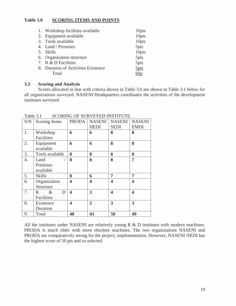
Table 3.0 SCORING ITEMS AND POINTS
1. Workshop facilities available 10pts 2. Equipment available 10pts 3. Tools available 10pts 4. Land / Premises 5pts 5. Skills 10pts 6. Organization structure 5pts 7. R & D Facilities 5pts 8. Duration of Activities Existence 5pts
Total 60p
3.3 Scoring and Analysis Scores allocated in line with criteria shown in Table 3.0 are shown in Table 3.1 below for all organizations surveyed. NASENI Headquarters coordinates the activities of the development institutes surveyed.
Table 3.1 SCORING OF SURVEYED INSTITUTE. S/N Scoring Items PRODA NASENI
HEDI NASENI SEDI
NASENI EMDI
1. Workshop Facilities
6 6 8 8
2. Equipment available
6 6 8 8
3. Tools available 8 8 8 8 4. Land /
Premises available
8 8 8 7
5. Skills 8 6 7 7 6. Organization
Structure 4 4 4 4
7. R & D Facilities
4 3 4 4
8. Existence Duration
4 2 3 3
9. Total 48 43 50 49
All the institutes under NASENI are relatively young R & D institutes with modern machines. PRODA is much older with more obsolete machines. The two organizations NASENI and PRODA are comparatively strong for the project, implementation. However, NASENI /SEDI has the highest score of 50 pts and so selected.
20
4.0 TECHNICAL ANALYSIS
4.1 Basic Concept and Selection of Turbine.
Hydro – turbines are usually designed for specific applications and outputs, and services depending upon how much water is available every year. A good understanding of energy requirements and characteristics of water resources is essential for proper selection of hydro – turbine Scheme. The selection of turbine is based on the head, the flow rate and output rating. The three categories of hydro schemes are:
• High head – 150m above • Medium head – 20m to 150m • Low head – 2m to 20m
Low head schemes are generally Run - of – River Schemes with a low high barrage or weir across a river or canal. An analysis of Table 2.2 shows the bulk of the sites to be exploited are in a head range of 2.65m – 29m with the exception of the waterfall (230m)
4.2 Types of Turbines There are two common classifications of turbine. The reaction turbine and impulse turbine and they are dictated by the water flow action and structural features. It is further differentiated by the flow direction in the passage of the runner. The turbine may further be classified by its arrangement of shaft as vertical and horizontal, and by its feature as fixed blade and adjustable blade etc.
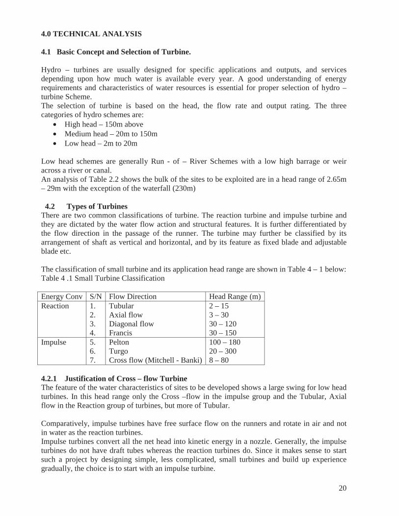
The classification of small turbine and its application head range are shown in Table 4 – 1 below: Table 4 .1 Small Turbine Classification
Energy Conv S/N Flow Direction Head Range (m)Reaction 1.
2. 3. 4.
Tubular Axial flow Diagonal flow Francis
2 – 15 3 – 30 30 – 120 30 – 150
Impulse 5. 6. 7.
Pelton Turgo Cross flow (Mitchell - Banki)
100 – 180 20 – 300 8 – 80
4.2.1 Justification of Cross – flow Turbine The feature of the water characteristics of sites to be developed shows a large swing for low head turbines. In this head range only the Cross –flow in the impulse group and the Tubular, Axial flow in the Reaction group of turbines, but more of Tubular.
Comparatively, impulse turbines have free surface flow on the runners and rotate in air and not in water as the reaction turbines. Impulse turbines convert all the net head into kinetic energy in a nozzle. Generally, the impulse turbines do not have draft tubes whereas the reaction turbines do. Since it makes sense to start such a project by designing simple, less complicated, small turbines and build up experience gradually, the choice is to start with an impulse turbine.
21
The energy generated is equally important in the choice of turbines. Most of the sites to be developed are below 500KW capacity. In the case of power output below 500KW, the Cross – flow competes well with Francis and Pelton turbines. Similarly, turbines with relatively low power outputs are likely to be horizontally mounted and has a wide range of relative discharge 0.4 > Q/Q1 < 1.0 Hence, the Cross – flow turbine is recommended for ease of manufacture and ‘leap – frogging’ the technology for domestication in the Country.
4.3 Crossflow (Banki) Turbine.
The Banki turbine (also known as the Michell, Crossflow or Ossberger turbine) is a hydropower system similar in appearance to an over-shot water wheel. Unlike the water wheel, however, it uses a nozzle and blades instead of buckets. The "middle" of the Banki turbine is left open and the blades that would normally form the walls of the buckets are angled. It is, in effect, a "leaky" water wheel.
Water flowing into the top of the turbine not only spins the wheel by its weight, but as it flows past the blades and into the middle of the turbine, its direction is changed. This extracts additional power via Newton's Third Law. A venturi enhances this effect by funneling the water at a high speed onto the blades.
The Banki turbine uses concepts from both impulse and reaction turbine design. This allows it to perform well in a wide range of heads. The system is somewhat similar to the Pelton wheel in concept, but requires less engineering in the wheel itself.
The Banki turbine has lower efficiency than other turbine designs but enjoys a niche market for low cost and home made installations. A reasonably efficient turbine runner can be constructed from pipe sections that are slit to form the blades (70% - 80% efficiency at 10 feet of head). The venturi and associated plumbing may be fabricated with sheet metal tools. It is somewhat more complex than in an over-shot wheel, but by no means difficult. A locally made Crossflow (Banki) turbine that has same power as a large Diesel engine is within the means of most small and amateur workshops.
22
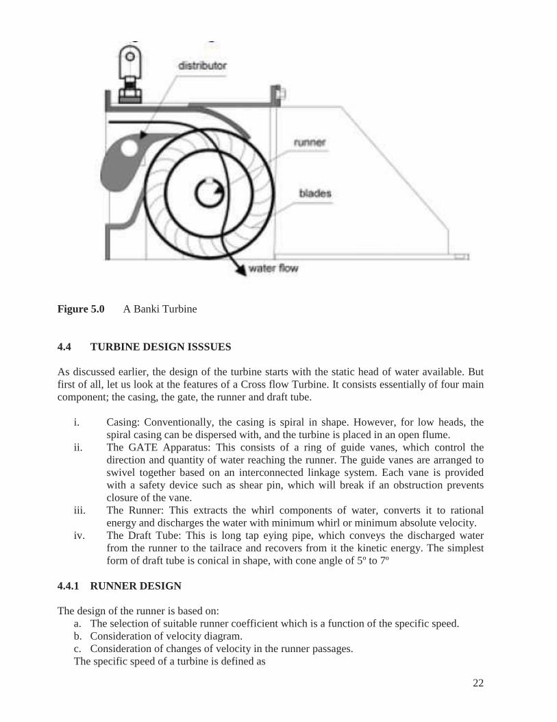
Figure 5.0 A Banki Turbine
4.4 TURBINE DESIGN ISSSUES
As discussed earlier, the design of the turbine starts with the static head of water available. But first of all, let us look at the features of a Cross flow Turbine. It consists essentially of four main component; the casing, the gate, the runner and draft tube.
i. Casing: Conventionally, the casing is spiral in shape. However, for low heads, the spiral casing can be dispersed with, and the turbine is placed in an open flume.
ii. The GATE Apparatus: This consists of a ring of guide vanes, which control the direction and quantity of water reaching the runner. The guide vanes are arranged to swivel together based on an interconnected linkage system. Each vane is provided with a safety device such as shear pin, which will break if an obstruction prevents closure of the vane.
iii. The Runner: This extracts the whirl components of water, converts it to rational energy and discharges the water with minimum whirl or minimum absolute velocity.
iv. The Draft Tube: This is long tap eying pipe, which conveys the discharged water from the runner to the tailrace and recovers from it the kinetic energy. The simplest form of draft tube is conical in shape, with cone angle of 5º to 7º
4.4.1 RUNNER DESIGN
The design of the runner is based on: a. The selection of suitable runner coefficient which is a function of the specific speed. b. Consideration of velocity diagram. c. Consideration of changes of velocity in the runner passages. The specific speed of a turbine is defined as
23
ns =N Where ns = specific speed N = rotational speed of turbine rev/mm W = Power output of turbine H = effective static head of water The runner coefficient defined as
= u = is the runner coefficient at a given point.
u = is peripheral velocity at that point Charts are available to determine at various points on the runner as a function of ns, the specific speed at the inner and outer profiles and the water entry and water exit edges.
The actual runner dimensions are obtained by using the equation
D = 60u ----------------------------------------------------------------- 1.0 LlN Where D is the diameter at the point considered.
Graphs also enable us to determine the height of the guide vane B
Consideration of the velocity diagram enables us to calculate the guide vane exit angle and the runner blade inlet angle.
The number of vanes can be determined based on the speed.
Having determined the dimension of the turbine runner, we must now look at the other critical areas of the designs. The runner must be supported by a shaft. To design the shaft, we must decide on the nature of bearing supports we need. It will be safe to assume that power out – take from the shaft is by means of a pulley to the gearbox and alternator.
For the bearing supports, we have a choice of one thrust bearing with two guide bearings or one tapered roller bearing with one guide bearing. If the turbine runner is not too heavy, the 2nd alternative will suffice. But if it is too heavy, then it is best to use a thrust bearing with two guide bearings. With this decision, we can design the shaft, which is a straightforward calculation.
4.5 CHOICE OF MATERIALS AND MANUFACTURE METHODS
4.5.1 Turbine Runner: The turbine runner can be cast integrally in plain carbon or stainless steel. One best practice is to cast the hub, and form the blades from steel plates. If it is desired, the surfaces could be protected by chrome plating. The blades are then bolted to the hub.
4.5.2 Shaft: The shaft is machined from carbon steel bar stock – plan carbon steel. At this stage one machine shop and one foundry are sufficient.

24
4.5.3 Bearing Housing: Sometimes, it may be difficult to obtain standard bearing locally. In that case, they can be made by casting and machining, or machining from bar stock. One area that needs special attention in the bearing and housing is the sealing and lubrication arrangement.
4.5.4 The Gate Apparatus: The top and bottom discs can be made from mild steel plates. The same with the guide vanes. The top pins of the guide vanes rotate in either brass or Teflon bushes.
4.5.5 Pulley: This will be machined from bar stock or may be produced by casting and machining.
4.5.6 Gear Box: Where it is not possible to purchase a gear system with the right speed ratio, the gear system can be produced by machining.
4.6 Recommended Manufacturing Procedure The following procedure is suggested for the actualization of the project:
1. Select site 2. Carry out hydrological and load surveys. – Site capacity determination 3. Constitute turbine sub-team, and provide with data on head, power requirement and
maximum water out – take. 4. The team carries out the design up to the stage of working drawings and detailed methods
of production. The team will also identify where each component will be made. At this stage one machine shop and one foundry are sufficient. The design could be completed within one month.
5. The components are manufactured with adequate supervision by the team – two months 6. The components are subjected to necessary quality control and are assembled and tested
in-house. 7. At the design stage, the basic requirement for flume, the turbine support structure and the
draft tube will be determined, and given t o the site design team. The data should include foundation and bolting down requirements.
8. When the site structures are ready, the turbine will be installed on site, and basic test – runs will commence.
9. On successful commission of the power plant, seminars and workshops on the process and lessons learnt will be organized to train more potential small turbine manufactures.
4.7 Work plan Spreadsheet A work plan on spreadsheet is attached – A- 4 and made up of the following major activities:
Identification and Preliminary Assessment of facilities. Team of Experts Visit Bidding, Selection and Award of contacts Additional facilities Procurement Real and Model SHP Components Production of Selected SHP components Capacity building: Training the Trainers Fabrication of SHP components parts
25
Assembly and Testing Commercialization.
4.7.1 Assessment of Facilities A basic requirement of workshop facilities and equipment/tools for designated workshops as shown in 3.0 was used by RC in carrying out a detailed survey of facilities for the R & D institutions listed below:
NASENI (HEDI), Kano NASENI (SEDI), Enugu PRODA Enugu NASENI (EMDI), Akure
4.7.2 Team of Experts Verification A brief report on surveyed sites shows inadequacy in specifications of some equipment as well as the functional capacity. This prompted a revisit to the following institution’s location:
NASENI (HEDI), Kano NASENI (SEDI), Enugu PRODA, Enugu NASENI (EMDI), Akure
The recommendation by the team of experts for additional facilities is shown in A – 4.2 The estimated cost of this activity is 5,000USD for 14days work duration.
4.7.3 Bidding, Selection and Contract Award In line with the Due Process Regulations in Nigeria, it is necessary to prepare a bidding document; publicly advertise the intention of procurement; open and assess submitted bids, select winners and award the contract for supply of the items bides. The duration for the activity is 30days with an estimated cost of 5,000.00USD
4.7.4 Procurement of Additional Facilities The procurement, shipment, delivery to project site, installation and testing of these additional facilities is projected for 6 weeks at an estimated cost of 1,000,000.00 USD.
4.7.5 Real Model SHP Component Procurement. In order to facilitate smooth production and training, the need to procure real and model SHP equipment becomes important and crucial. It is projected that identification; procurement and shipment should take 35days at an estimated cost of 60,000:00 USD.
4.7.6 SHP Component Production. In establishing and specifying standards to be adopted, existing documents such as IEC/TC-44, AHEC and IN-SHP should be of immense value. These specified standards will conform to international standards and ease the preparation of relevant engineering drawings, as well as the preparation of the manufacturing layout. These activities are projected for 60days at an estimated cost of 10,000: 00 USD.
4.7.7 Training the Trainers It is planned in the transfer of this technology; to train identified experts outside Nigeria and on return commission them on the local fabrication of hydro turbines.

26
In this respect UNIDO has put in place plans for the above and to be implemented as soon as firm commitment is made by all parties involved in the project. This activity primarily involves capacity Building in SHP Equipment Manufacturing. It is projected to cover a period of 65days at an estimated cost of 54,000:00USD
4.7.8 Fabrication of SHP Components The model SHP (sample) component parts, the manufacturing layout, and test equipments once in place at the designated workshop, signals commencement of fabrication. Once the components are fabricated, testing follows and then certification. The requirement and tolerance for each component part of SHP is given in detail in (6). The projected duration for this activity is 42days with an estimated cost of 69,000:00USD
4.7.9 Assembly and Testing The certified components parts are then moved to the designated workshop for assemble into integrated SHP equipment. The SHP equipment performance is then established as functioning equipment on a potential site earlier developed for same capacity of equipment. The duration for this activity is projected as 29days at an estimated cost of 10,000:00USD.
4.7.10 Commercialization A business plan is drawn up once the performance test is okay for the SHP equipment manufactured. An investor’s forum is then planned and implemented to commence the process of commercializing the product. The commercialization activity is projected for 24 days with an estimated cost of 25,000:00USD
4.7.11 Project Implementation Meetings As it is common, with all profits, it is necessary to hold regular, monthly meetings once the project commences. This provides the unique opportunity of nipping in the bud, some exigencies/issues/matters that have not been considered in the overall planning and design of the project. 11no meetings are planned for the whole project implementation duration at an estimated cost of 550:00 USD per meeting totaling 5,500:00USD.
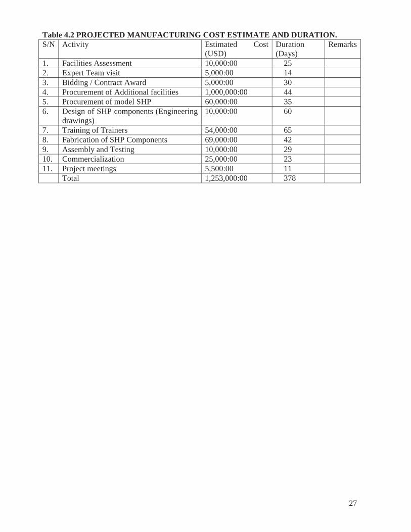
4.7.12 Project Implementation Cost. The Technical Analysis discussed above gives a project implementation cost estimate of 1,253,000:00 USD for an implementation period of 378days – Table 4.2
27
Table 4.2 PROJECTED MANUFACTURING COST ESTIMATE AND DURATION. S/N Activity Estimated Cost
(USD) Duration (Days)
Remarks
1. Facilities Assessment 10,000:00 25 2. Expert Team visit 5,000:00 14 3. Bidding / Contract Award 5,000:00 30 4. Procurement of Additional facilities 1,000,000:00 44 5. Procurement of model SHP 60,000:00 35 6. Design of SHP components (Engineering
drawings) 10,000:00 60
7. Training of Trainers 54,000:00 65 8. Fabrication of SHP Components 69,000:00 42 9. Assembly and Testing 10,000:00 29 10. Commercialization 25,000:00 23 11. Project meetings 5,500:00 11 Total 1,253,000:00 378
28
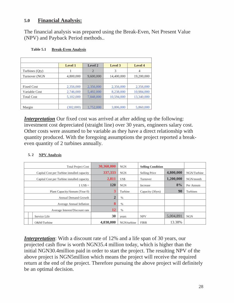
5.0 Financial Analysis: The financial analysis was prepared using the Break-Even, Net Present Value (NPV) and Payback Period methods..
Table 5.1 Break-Even Analysis
Level 1 Level 2 Level 3 Level 4 Turbines (Qty) 1 2 3 4 Turnover (NGN 4,800,000 9,600,000 14,400,000 19,200,000 Fixed Cost 2,356,000 2,356,000 2,356,000 2,356,000 Variable Cost 2,746,000 5,492,000 8,238,000 10,984,000 Total Cost 5,102,000 7,848,000 10,594,000 13,340,000
Margin (302,000) 1,752,000 3,806,000 5,860,000
Interpretation Our fixed cost was arrived at after adding up the following: investment cost depreciated (straight line) over 30 years, engineers salary cost. Other costs were assumed to be variable as they have a direct relationship with quantity produced. With the foregoing assumptions the project reported a break-even quantity of 2 turbines annually.
5. 2 NPV Analysis
Total Project Cost 30,360,000 NGN Selling Condition
Capital Cost per Turbine installed capacity 337,333 NGN Selling Price 4,800,000 NGN/Turbine
Capital Cost per Turbine installed capacity 2,811 US$ Turnover 1,200,000 NGN/month
1 US$ = 120 NGN Increase 8% Per Annum
Plant Capacity/Annum (Year 0) 3 Turbine Capacity (30yrs) 90 Turbines
Annual Demand Growth 2 %
Average Annual Inflation 8 %
Average Interest/Discount rate 12 %
Service Life 30 years NPV 5,004,891 NGN
O&M/Turbine 4,030,000 NGN/turbine FIRR 13.38%
Interpretation: With a discount rate of 12% and a life span of 30 years, our projected cash flow is worth NGN35.4 million today, which is higher than the initial NGN30.4million paid in order to start the project. The resulting NPV of the above project is NGN5million which means the project will receive the required return at the end of the project. Therefore pursuing the above project will definitely be an optimal decision.
29
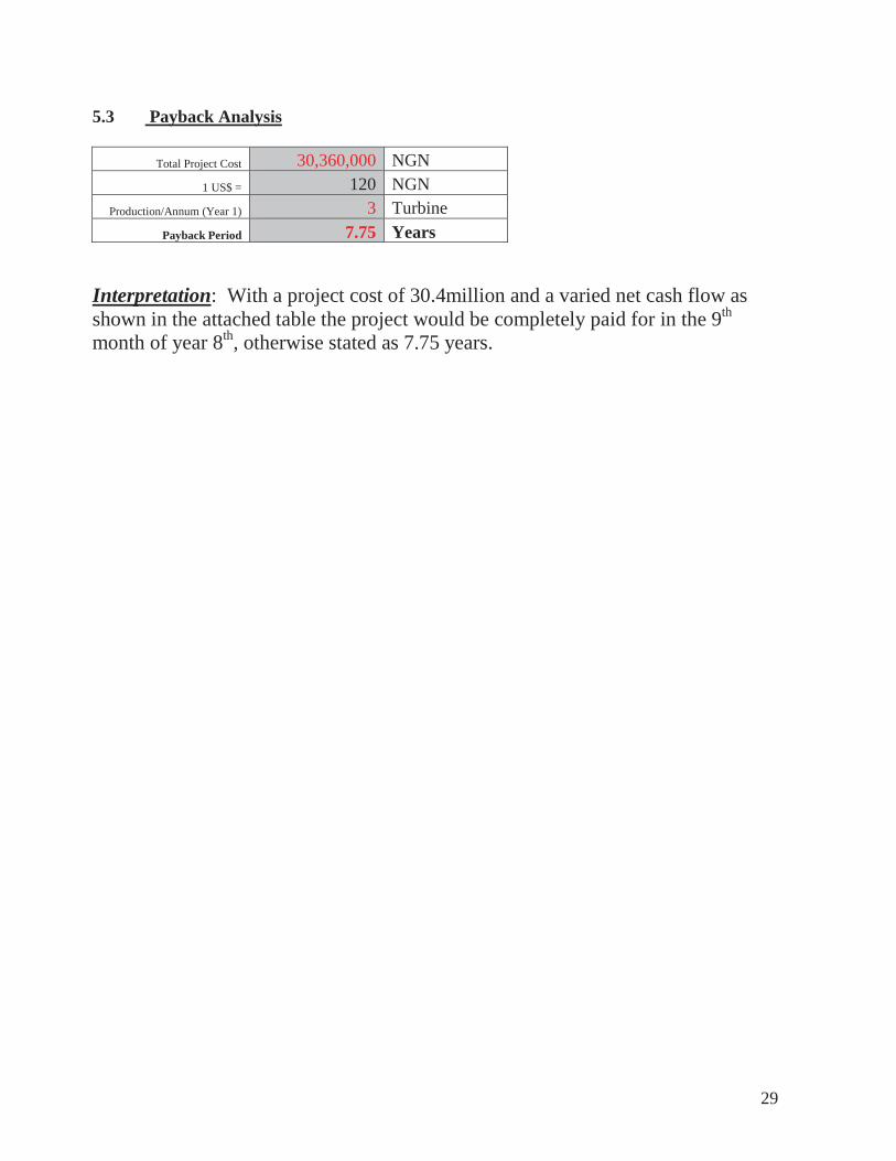
5.3 Payback Analysis
Total Project Cost 30,360,000 NGN 1 US$ = 120 NGN
Production/Annum (Year 1) 3 Turbine Payback Period 7.75 Years
Interpretation: With a project cost of 30.4million and a varied net cash flow as shown in the attached table the project would be completely paid for in the 9th
month of year 8th, otherwise stated as 7.75 years.
30
6.0 SUSTAINABILITY PLANS
When the local people in the communities are involved in the development of Small Hydro projects and the local content of the projects increases, installation costs are reduced. Security of equipment and investment are also guaranteed, as such are viewed as community investment. Examples from Kenya and other developing countries like Peru and Sri Lanka have shown that Small Hydro projects can be self sustaining and profitable.
Measures already in place, policy – wise, institutional framework, regulatory mechanisms e.t.c. are summarized as:
• Policy and Targets for SHP contribution to the Power Vision of Nigeria by FGN • Establishment and nurturing of appropriate and dynamic Science and Engineering
Infrastructure base for achieving home initiated and home sustained industrialization through the development of relevant processes, capital goods and equipment necessary for job creation, national economic well being and progress by NASENI.
• UNIDO – RC – SHP in Africa, Abuja established with the mandate of providing technical assistance required for the deployment of SHP for electricity generation in the African sub region.
• Training of trainers by UNIDO’s technical partners who will train private entrepreneurs for quick results and commercialization of product (Turbine) - SME
• Producing under license of EU Company for competitiveness in the international and regional markets.
• Low production cost for competitive pricing • Continuous Sensitization and awareness creation of the communities on benefits of SHP
towards barriers removal • Mechanism for Productive energy uses of SHP plants as demonstrated by UNIDO Pilot
SHP projects in Enugu and Bauchi. • Education Information dissemination of benefits of SHP to communities on regular basis. • Electricity Act 2005 encouraging Public Private Participation (PPP) as well as
Independent Power Production (IPP) • Scaling – up, replicating and mainstreaming as tools for linking micro level energy
activities to macro – level national priorities e.g. NEEDs II, NAPEP, MGD etc • Markets creation for SHP through new financing options – Local funds, aids and grants,
foreign direct investment (DFID,WB,AFDB) and Carbon financing. • NATIONAL Energy Policy (NEP), Energy Master plan (EMP) and regulatory framework
(NERC) • Appropriate financial mechanism for scaling up SHP projects under consideration by FGN • South – South Cooperation encouraged by UNIDO.
7.0 Conclusion African countries have significant hydropower and specifically SHP sources which if exploited can contribute greatly to the overall energy needs of the continent. Exploiting these resources will require overcoming the major technical, institutional and financial barriers. However, the significant lesson for countries in Africa is to scale-up the SHP in the continent. Presently, the continent has the highest rate of return on investment and this feature should be fully exploited for the development of small hydropower.

31
Sustainability plans for the project must recognize and put in place the following:
Regulatory framework – Predictable Stable investment framework Long – term strategic policy commitments – Govts Identifying indicators that drive sustainability of clean energy investments Stabilizing these indicators to allow sustainability returns Engaging stakeholders – statutory, non – stability and public consultation.
Energy is central to sustainable development and poverty reduction efforts. It affects all aspects of development – social, economic and environmental – including livelihood access to water, agricultural productivity, health, population levels, education and gender – related issues.
World leaders have pledged to achieve the millennium Development Goals, including the overarching goal of cutting poverty in half by 2015. Meeting the M.D.G will require concerted international efforts to bring about major increases in people’s access to modern energy services in D.C.
32
REFERENCES.
1. Ogunlade R; Davidson and Michal Conteh, Energy and the M.D.Gs in Africa, Technical Paper for M.D.Gs
2. Esan Ayodele. Afolabi; Nigeria country Paper “Access to Energy Services for Rural and Peri Rural Population for the Achievement of M.D.Gs, 2006.”
3. FGN/FMPS – Renewable ENERGY Master plan for Nigeria4. Tong. Jiandong and Petr. Fleischer, Small Hydraulic Turbine, IN-SHP,2000 5. UNDP, Expanding Access to modern Energy Services – Replicating, Scaling up and
Mainstreaming at the local level. 6. Esan. Ayodele Afolabi, UNIDO Regional Centre and Small Hydro Power Development
in Africa, International conference on Renewable Energy in Africa, Dakar, Senegal, 16th
– 18th April, 2008. 7. Ogunlade. R Davidson, Scaling up markets for Renewable Energy in Africa,
“International Conference on Renewable Energy in Africa, Dakar, Senegal, 16th – 18th
April, 2008.

33
A – 3.1
WORKSHOP REQUIREMENT
1. Machine shop 2. Working shop 3. Forging shop 4. Foundry shop 5. Repair shop 6. Substation 7. Electrical shop 8. Quality Control shop

34
A – 3.2
REQUIRED MANUFACTURING EQUIPMENT
1. Circular saw 2. Hand saw 3. Centre Lathe – Width 900mm min Height 250mm min 4. Milling machine 5. Planning/ shaping machine 6. Arc welding equipment 7. Boring machine 8. Drilling machine 9. Grinding machine 10. Bending machine / Press 11. Gas cutting equipment 12. Shearing machine
REQUIRED TOOLS.
13. Hammers 14. Screw drivers 15. Allen key set 16. Open spanner set 17. Ring spanner set 18. Socket spanner set 19. Files, chisels 20. Centre punch 21. Vernier calipers 22. Puller 23. Vice etc.
35
A - 3.3
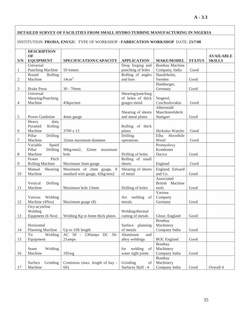
DETAILED SURVEY OF FACILITIES FROM SMALL HYDRO TURBINE MANUFACTURING IN NIGERIA
INSTITUTION: PRODA, ENUGU. TYPE OF WORKSHOP : FABRICATION WORKSHOP DATE: 23/7/08
S/N
DESCRIPTION OF EQUIPMENT SPECIFICATION/CAPACITY APPLICATION MAKE/MODEL STATUS
AVAILABLE SKILLS
1 Universal Punching Machine 50 tonnes
Drop forging and punching of holes
Bombay Machine Company, India Good
2 Round Rolling Machine 14cm3
Rolling of angles and bars
Hassleholm, Sweden Good
3 Brake Press 30 - 70mm Hamburger, Germany Good
4
Universal Shearing/Punching Machine 45kpa/mm
Shearing/punching of holes of thick guages metal
Stogerel, Czechoslovakia Good
5 Power Guidotine 4mm guage Shearing of sheets and metal plates
Albertstahl Maschinenfabrik Stuttgart Good
6
Heavy duty Pyramid Rolling Machine 3700 x 13
Rolling of thick plates Herkulus Watzler Good
7 Pillar Drilling Machine 32mm maximum diameter
Drilling operations
Elha Hovelhife Westf Good
8
Variable Speed Pillar Drilling Machine
90kg/mm2; 32mm maximum hole Drilling of holes
Promyslovy Kombimet Dacice Good
9 Power Pitch Rolling Machine Maximum 3mm guage
Rolling of small sheets England Good
10 Manual Shearing Machine
Maximum of 2mm guage, 8 standard wire guage, 42kg/mm2
Shearing of sheets of metal
England, Edward and Co. Good
11 Vertical Drilling Machine Maximum hole 13mm Drilling of holes
Associated British Machine tools Good
12 Various Welding Machine (4Nos) Maximum guage (8)
Arc welding of metals
Various Company Germany Good
13
Oxy-acyteline Welding Equpment (6 Nos) Welding Kp to 6mm thick plates
Welding/thermal cutting of metals Gloor, England Good
14 Horizontal Planning Machine Up to 10ft length
Surface planning of metals
Bombay Machinery Company India Good
15 Tic Welding Equipment
AC 50 - 230amps DC 56- 21amps
Aluminum and alloy weldings BOC England Good
16 Seam Welding Machine 185wg
for welding of water tight joints
Bombay Machinery Company India Good
17 Surface Grinding Machine
Continous (max. length of bay - 6ft)
Grinding of Surfaces Skill - 4
Bombay Machinery Company India Good Overall 4
36
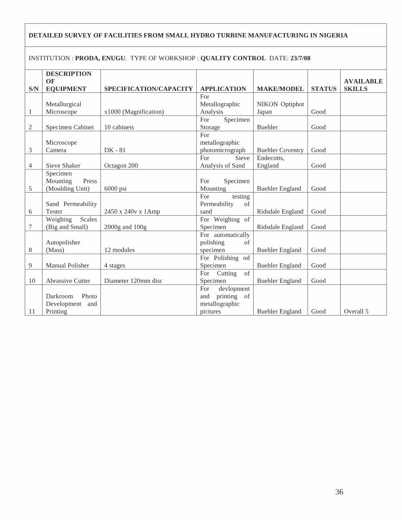
DETAILED SURVEY OF FACILITIES FROM SMALL HYDRO TURBINE MANUFACTURING IN NIGERIA
INSTITUTION : PRODA, ENUGU. TYPE OF WORKSHOP : QUALITY CONTROL DATE: 23/7/08
S/N
DESCRIPTION OF EQUIPMENT SPECIFICATION/CAPACITY APPLICATION MAKE/MODEL STATUS
AVAILABLE SKILLS
1 Metallurgical Microscope x1000 (Magnification)
For Metallographic Analysis
NIKON Optiphot Japan Good
2 Specimen Cabinet 10 cabinets For Specimen Storage Buehler Good
3 Microscope Camera DK - 81
For metallographic photomicrograph Buehler Coventry Good
4 Sieve Shaker Octagon 200 For Sieve Analysis of Sand
Endecotts, England Good
5
Specimen Mounting Press (Moulding Unit) 6000 psi
For Specimen Mounting Buehler England Good
6 Sand Permeability Tester 2450 x 240v x 1Amp
For testing Permeability of sand Ridsdale England Good
7 Weighing Scales (Big and Small) 2000g and 100g
For Weighing of Specimen Ridsdale England Good
8 Autopolisher (Mass) 12 modules
For automatically polishing of specimen Buehler England Good
9 Manual Polisher 4 stages For Polishing od Specimen Buehler England Good
10 Abrassive Cutter Diameter 120mm disc For Cutting of Specimen Buehler England Good
11
Darkroom Photo Development and Printing
For devlopment and printing of metallographic pictures Buehler England Good Overall 5

37
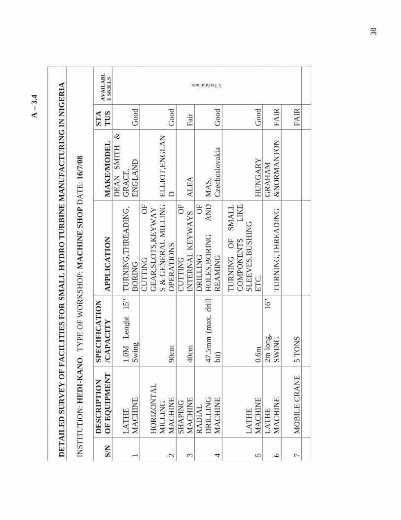
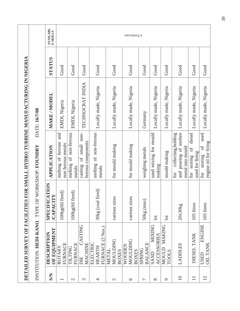
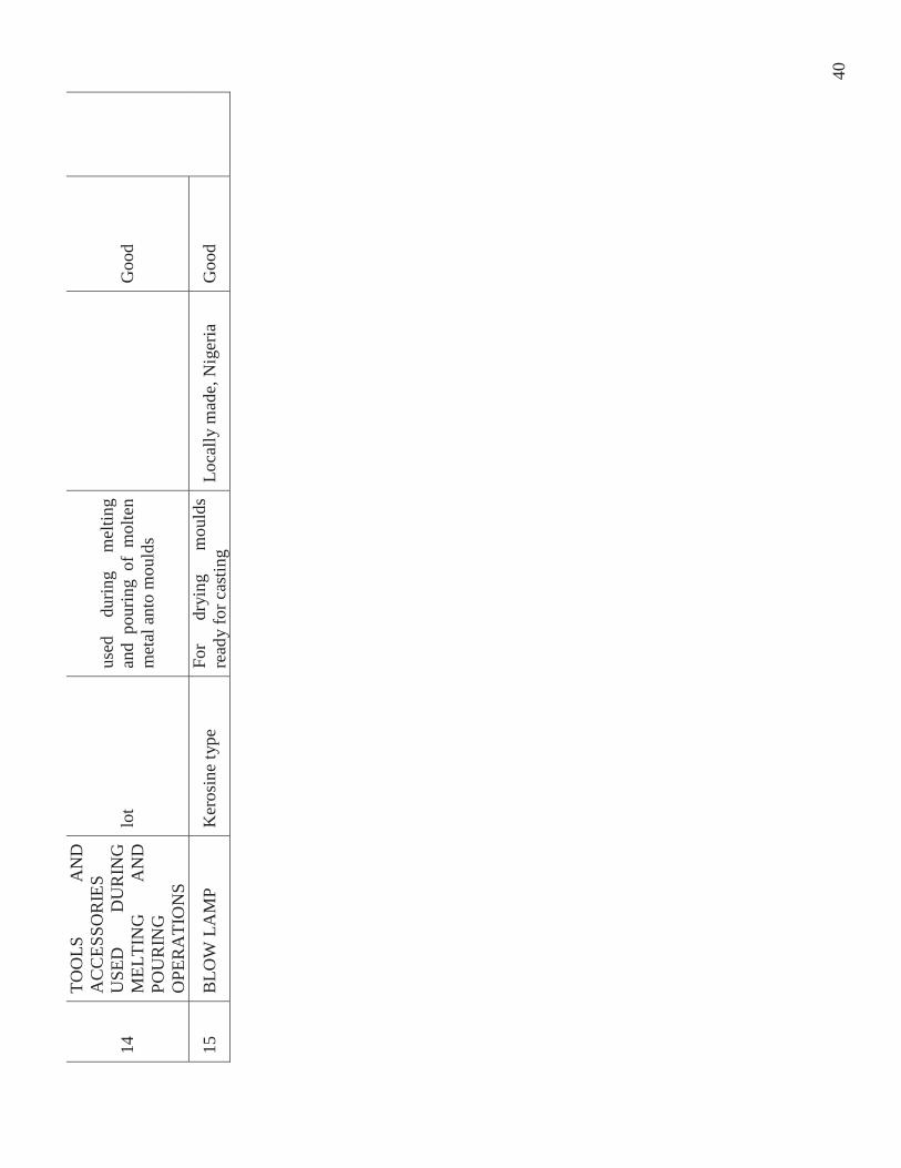
DETAILED SURVEY OF FACILITIES FROM SMALL HYDRO TURBINE MANUFACTURING IN NIGERIA
INSTITUTION: PRODA, ENUGU. TYPE OF WORKSHOP : PATTERN SHOP. DATE: 23/7/08
S/N
DESCRIPTION OF EQUIPMENT SPECIFICATION/CAPACITY APPLICATION MAKE/MODEL STATUS
AVAILABLE SKILLS
1 Wood Circular Saw - Heavy duty 18mm thickness Cutting of Woods
T. Robinson & sons England Good
2 Wood Surface Plaining Machine 18mm thickness
Smoothing of Wood Surfaces Guillet England Good
3 Universal Wood Plaining 12mm thickness
Continous Plaining of wood surfaces Guillet England Good
4 Band-Saw Wood Cutting Machine 30 inches
General wood cutting
T. Robinson & sons England Good
5 Moticing Machine 25mm - 100mm Punching of holes for wood joints
T. Robinson & sons England Good
6 Radial Arm-Saw 24 inches travel length Circular wood cutting De Walt England Good
7 Wood - Cutting M/c 6500 upm Plaining of wood
HOBENLLE ZUSATZGERAT Good
8 Black-Smith Forge 1440rpm Forge work
ALLOSA Willian AlldayEngland Good
9 Air Compressor 300kgkm2 (115 psi) Compresses air supply
BROOMWADE England Good Overall 4
38
A –
3.4
DE
TA
ILE
D S
UR
VE
Y O
F FA
CIL
ITIE
S FO
R S
MA
LL
HY
DR
O T
UR
BIN
E M
AN
UFA
CT
UR
ING
IN N
IGE
RIA
INST
ITU
TIO
N: H
ED
I-K
AN
O.
TYPE
OF
WO
RK
SHO
P: M
AC
HIN
E S
HO
P D
ATE
: 16/
7/08
S/N
D
ESC
RIP
TIO
N
OF
EQ
UIP
ME
NT
SP
EC
IFIC
AT
ION
/CA
PAC
ITY
A
PPL
ICA
TIO
N
MA
KE
/MO
DE
L
STA
TU
S A
VA
ILA
BL
E S
KIL
LS
1 LA
THE
MA
CH
INE
1.0M
Le
nght
15
" Sw
ing
TU
RN
ING
,TH
REA
DIN
G,
BO
RIN
G
DEA
N
SMIT
H
&
GR
AC
E,
ENG
LAN
D
Goo
d
5 Technicians
2
HO
RIZ
ON
TAL
MIL
LIN
G
MA
CH
INE
90cm
CU
TTIN
G
OF
GEA
R,S
LOTS
,KEY
WA
YS
& G
ENER
AL
MIL
LIN
G
OPE
RA
TIO
NS
ELLI
OT,
ENG
LAN
D
Goo
d
3 SH
API
NG
M
AC
HIN
E 40
cm
CU
TTIN
G
OF
INTE
RN
AL
KEY
WA
YS
ALF
A
Fair
4
RA
DIA
L D
RIL
LIN
G
MA
CH
INE
47.5
mm
(m
ax.
drill
bi
t)
DR
ILLI
NG
O
F H
OLE
S,B
OR
ING
A
ND
R
EAM
ING
M
AS,
C
zech
oslo
vaki
a G
ood
5 LA
THE
MA
CH
INE
0.6m
TUR
NIN
G
OF
SMA
LL
CO
MPO
NEN
TS
LIK
E SL
EEV
ES,B
USH
ING
ET
C.
HU
NG
AR
Y
Goo
d
6 LA
THE
MA
CH
INE
2m lo
ng,
16"
SW
ING
TU
RN
ING
,TH
REA
DIN
G
GR
AH
AM
&
NO
RM
AN
TON
FA
IR
7 M
OB
ILE
CR
AN
E 5
TON
S
FA
IR
39
DE
TA
ILE
D S
UR
VE
Y O
F FA
CIL
ITIE
S FO
R S
MA
LL
HY
DR
O T
UR
BIN
E M
AN
UFA
CT
UR
ING
IN N
IGE
RIA
INST
ITU
TIO
N: H
ED
I-K
AN
O.
TYPE
OF
WO
RK
SHO
P: F
OU
ND
RY
DA
TE: 1
6/7/
08
S/N
D
ESC
RIP
TIO
N
OF
EQ
UIP
ME
NT
SP
EC
IFIC
AT
ION
/CA
PAC
ITY
A
PPL
ICA
TIO
N
MA
KE
/ M
OD
EL
ST
AT
US
AV
AIL
AB
LE
SK
ILL
S
1 R
OTA
RY
FU
RN
AC
E 10
0kg(
0il f
ired)
m
eltin
g of
fer
rous
and
no
n fe
rrou
s met
als
EMD
I, N
iger
ia
Goo
d
4 Technicians
2 TI
LTIN
G
FUR
NA
CE
100k
g(0i
l fire
d)
mel
ting
of n
on-f
erro
us
met
als
EMD
I, N
iger
ia
Goo
d
3 D
IE
CA
STIN
G
MA
CH
INE
ca
stin
g of
sm
all
non-
ferr
ous c
ompo
nent
s TE
CH
NO
CR
AT
IND
IA
Goo
d
4 EL
ECTR
IC
HEA
RTH
FU
RN
AC
E (2
Nos
.) 30
kg (c
oal f
ired)
m
eltin
g of
non
-fer
rous
m
etal
s Lo
cally
mad
e, N
iger
ia
Goo
d
5 M
ETA
L M
OU
LDIN
G
BO
XES
va
rious
size
s fo
r mou
ld m
akin
g Lo
cally
mad
e, N
iger
ia
Goo
d
6 W
OO
DEN
M
OU
LDIN
G
BO
XES
va
rious
size
s fo
r mou
ld m
akin
g Lo
cally
mad
e, N
iger
ia
Goo
d
7 SP
RIN
G
BA
LAN
CE
50kg
(max
) w
eigh
ing
met
als
Ger
man
y G
ood
8 SA
ND
M
IXIN
G
AC
CES
SOR
IES
lot
sand
mix
ing
for
mou
ld
mak
ing
Loca
lly m
ade,
Nig
eria
G
ood
9 M
OU
LD
MA
KIN
G
TOO
LS
lot
mou
ld m
akin
g Lo
cally
mad
e, N
iger
ia
Goo
d
10
LAD
DLE
S 20
x30k
g fo
r co
llect
ing,
hold
ing
and
pour
ing
of m
olte
n m
etal
into
mou
ld
Loca
lly m
ade,
Nig
eria
G
ood
11
DIE
SEL
TAN
K
105
litre
s fo
r st
orin
g of
di
esel
us
ed fo
r firi
ng
Loca
lly m
ade,
Nig
eria
G
ood
12
USE
D
ENG
INE
OIL
TA
NK
10
5 lit
res
for
stor
ing
of
used
en
gine
oil
for f
iring
Lo
cally
mad
e, N
iger
ia
Goo
d
40
14
TOO
LS
AN
D
AC
CES
SOR
IES
USE
D
DU
RIN
G
MEL
TIN
G
AN
D
POU
RIN
G
OPE
RA
TIO
NS
lot
used
du
ring
mel
ting
and
pour
ing
of m
olte
n m
etal
ant
o m
ould
s
Goo
d
15
BLO
W L
AM
P K
eros
ine
type
Fo
r dr
ying
m
ould
s re
ady
for c
astin
g Lo
cally
mad
e, N
iger
ia
Goo
d
41
DE
TA
ILE
D S
UR
VE
Y O
F FA
CIL
ITIE
S FO
R S
MA
LL
HY
DR
O T
UR
BIN
E M
AN
UFA
CT
UR
ING
IN N
IGE
RIA
INST
ITU
TIO
N: H
ED
I-K
AN
O.
TYPE
OF
WO
RK
SHO
P : P
AT
TE
RN
SH
OP.
DA
TE: 1
6/7/
08
S/N
D
ESC
RIP
TIO
N
OF
EQ
UIP
ME
NT
SP
EC
IFIC
AT
ION
/ C
APA
CIT
Y
APP
LIC
AT
ION
M
AK
E/M
OD
EL
ST
AT
US
AV
AIL
AB
LE
SK
ILL
S
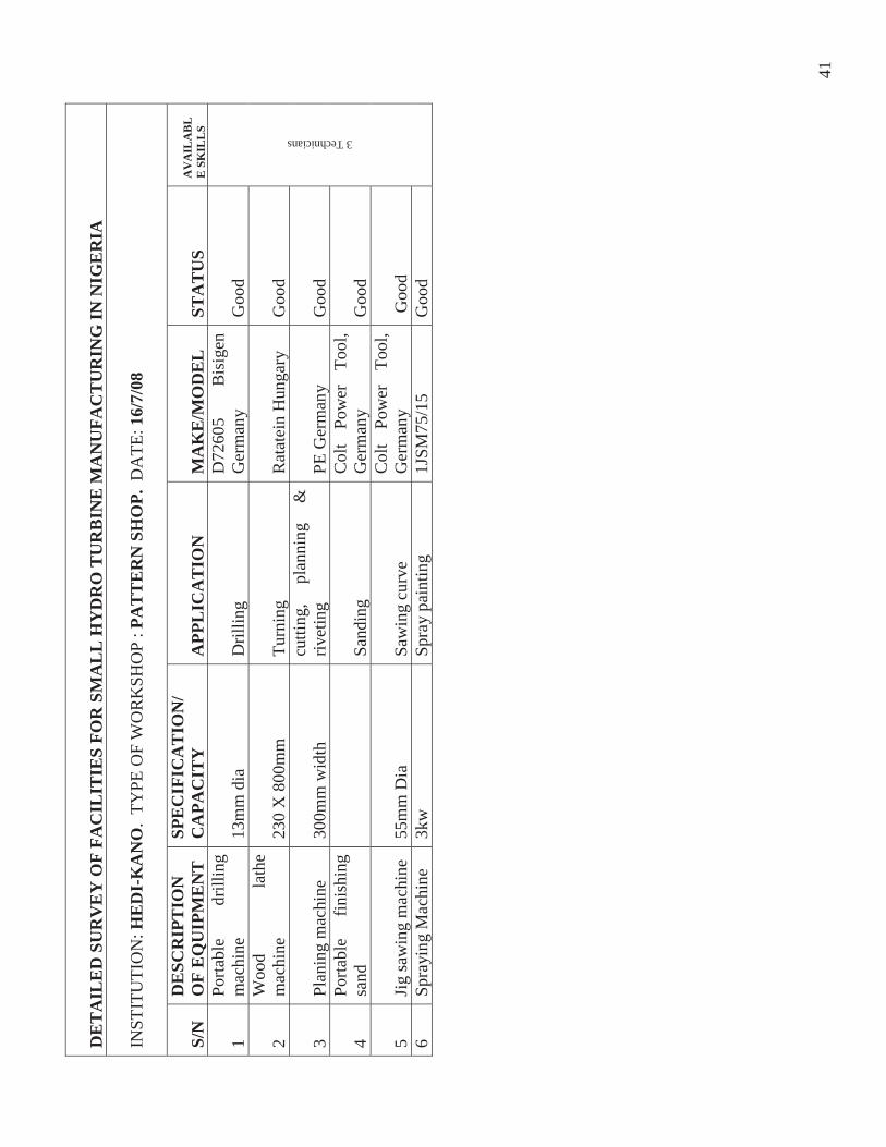
1 Po
rtabl
e dr
illin
g m
achi
ne
13m
m d
ia
Dril
ling
D72
605
Bis
igen
G
erm
any
Goo
d
3 Technicians
2 W
ood
lath
e m
achi
ne
230
X 8
00m
m
Turn
ing
Rat
atei
n H
unga
ry
Goo
d
3 Pl
anin
g m
achi
ne
300m
m w
idth
cu
tting
, pl
anni
ng
&
rivet
ing
PE G
erm
any
Goo
d
4 Po
rtabl
e fin
ishi
ng
sand
Sand
ing
Col
t Po
wer
To
ol,
Ger
man
y G
ood
5 Ji
g sa
win
g m
achi
ne
55m
m D
ia
Saw
ing
curv
e C
olt
Pow
er
Tool
, G
erm
any
Goo
d 6
Spra
ying
Mac
hine
3k
w
Spra
y pa
intin
g 1J
SM75
/15
Goo
d
42
DE
TA
ILE
D S
UR
VE
Y O
F FA
CIL
ITIE
S FO
R S
MA
LL
HY
DR
O T
UR
BIN
E M
AN
UFA
CT
UR
ING
IN N
IGE
RIA
INST
ITU
TIO
N: H
ED
I-K
AN
O
TYPE
OF
WO
RK
SHO
P:
FAB
RIC
AT
ION
SH
OP
DA
TE:
16/0
7/08
S/N
D
ESC
RIP
TIO
N
OF
EQ
UIP
ME
NT
SP
EC
IFIC
AT
ION
/ C
APA
CIT
Y
APP
LIC
AT
ION
M
AK
E/
MO
DE
L
STA
TU
S A
VA
LA
IBL
E S
KIL
LS
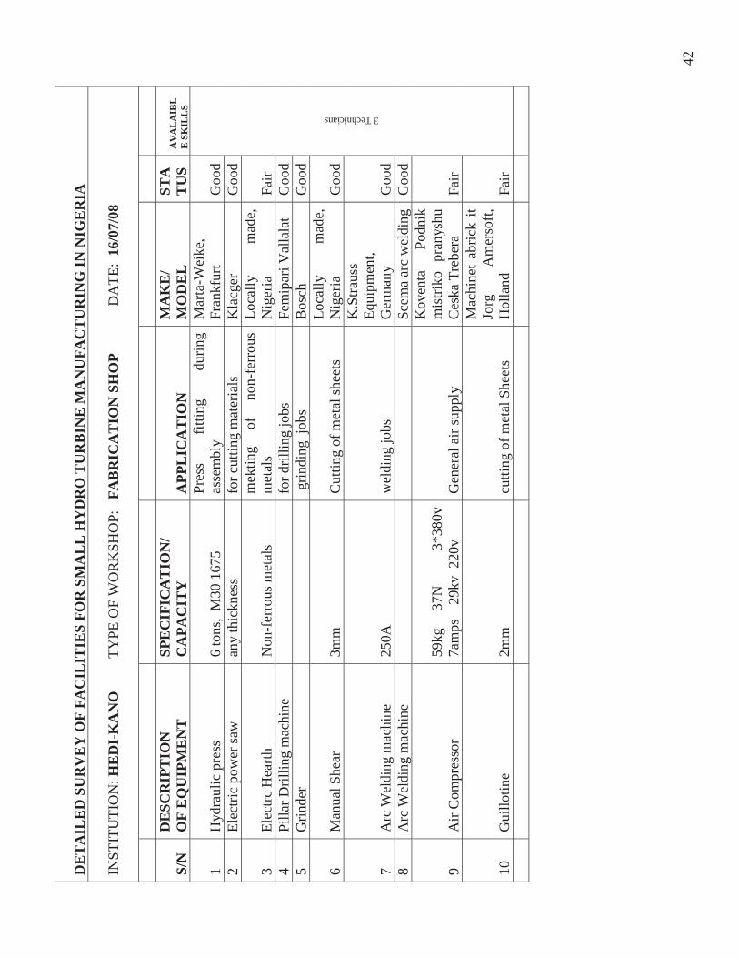
1 H
ydra
ulic
pre
ss
6 to
ns,
M30
167
5
Pres
s fit
ting
durin
g as
sem
bly
Mar
ta-W
eike
, Fr
ankf
urt
Goo
d
3 Technicians
2 El
ectri
c po
wer
saw
an
y th
ickn
ess
for c
uttin
g m
ater
ials
K
lacg
er
Goo
d
3 El
ectrc
Hea
rth
Non
-fer
rous
met
als
mek
ting
of
non-
ferr
ous
met
als
Loca
lly
mad
e,
Nig
eria
Fa
ir 4
Pilla
r Dril
ling
mac
hine
for d
rillin
g jo
bs
Fem
ipar
i Val
lala
t G
ood
5 G
rinde
r
grin
ding
job
s B
osch
G
ood
6 M
anua
l She
ar
3mm
C
uttin
g of
met
al sh
eets
Lo
cally
m
ade,
N
iger
ia
Goo
d
7 A
rc W
eldi
ng m
achi
ne
250A
w
eldi
ng jo
bs
K.S
traus
s Eq
uipm
ent,
Ger
man
y G
ood
8 A
rc W
eldi
ng m
achi
ne
Scem
a ar
c w
eldi
ngG
ood
9 A
ir C
ompr
esso
r 59
kg
37N
3*38
0v
7am
ps
29k
v 2
20v
G
ener
al a
ir su
pply
Kov
enta
Po
dnik
m
istri
ko p
rany
shu
Ces
ka T
rebe
ra
Fair
10
Gui
llotin
e 2m
m
cutti
ng o
f met
al S
heet
s
Mac
hine
t ab
rick
it Jo
rg
Am
erso
ft,
Hol
land
Fa
ir
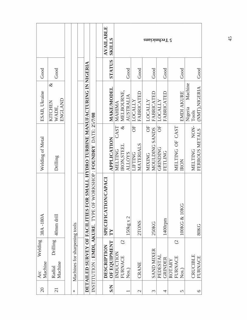
43
A
– 3
.5
DE
TA
ILE
D S
UR
VE
Y O
F FA
CIL
ITIE
S FO
R S
MA
LL
HY
DR
O T
UR
BIN
E M
AN
UFA
CT
UR
ING
IN N
IGE
RIA
IN
STIT
UTI
ON
: EM
DI,
AK
UR
E.
TYPE
OF
WO
RK
SHO
P : M
AC
HIN
E/F
AB
RIC
AT
ION
WO
RK
SHO
P D
ATE
: 25/
7/08
S/N
D
ESC
RIP
TIO
N
OF
EQ
UIP
ME
NT
SP
EC
IFIC
AT
ION
/ C
APA
CIT
Y
APP
LIC
AT
ION
M
AK
E/M
OD
EL
ST
AT
US
AV
AIL
AB
LE
SK
ILL
S
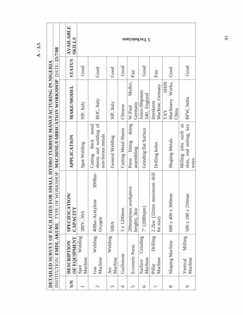
1 Sp
ot
Wel
ding
M
achi
ne
380V
, 50A
Sp
ot W
eldi
ng
SIP,
Ital
y G
ood
5 Technicians
2 G
as
Wel
ding
M
achi
ne
40B
ar-A
cety
lene
30
0Bar
-O
xyge
n
Cut
ting
thic
k m
etal
sh
eets
and
wel
ding
of
non-
fero
us m
etal
s B
OC
, Ita
ly
Goo
d
3 A
rc
Wel
ding
M
achi
ne
500A
G
ener
al W
eldi
ng
SI
P, It
aly
Goo
d
4 G
uillo
tone
3
x 12
00m
m
Cut
ting
Met
al S
heet
s C
hine
se
Goo
d
5 Ec
cent
ric P
ress
28
0mm
(max
.wor
kpie
ce
heig
ht),
3kw
Pr
ess
fittin
g du
ing
asse
mbl
ing
W.P
aul
Mul
ler,
Ger
man
y Fa
ir
6 Su
rfac
e G
rindi
ng
Mac
hine
7"
(288
0rpm
) G
rindi
ng fl
at S
urfa
ce
Jone
s-Sh
ipm
an
540,
Eng
land
G
ood
7 Pi
llar
Dril
ling
Mac
hine
2.
2kw
(32
mm
max
imum
dril
l bi
t siz
e)
Dril
ling
hole
s In
terk
rem
M
achi
ne, G
eman
y Fa
ir
8 Sh
apin
g M
achi
ne
600
x 40
0 x
300m
m
Shap
ing
Met
als
TAY
SH
IN
Mac
hine
ry
Wor
ks,
Chi
na
Goo
d
9 V
ertic
al
Mill
ing
Mac
hine
50
0 x
100
x 25
0mm
M
illin
g jo
bs s
uch
as
slot
s, en
d m
iling
, ke
y w
ays.
BFW
, Ind
ia
Goo
d
44
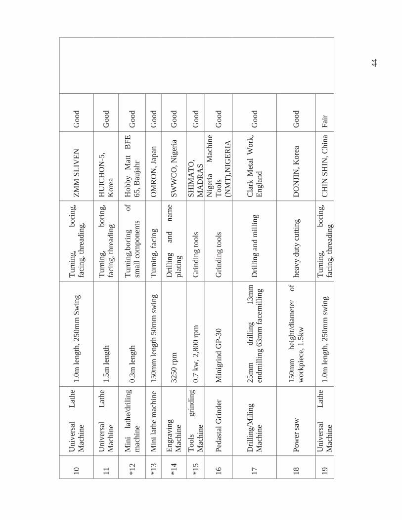
10
Uni
vers
al
Lath
e M
achi
ne
1.0m
leng
th, 2
50m
m S
win
g Tu
rnin
g,
borin
g,
faci
ng, t
hrea
ding
. ZM
M S
LIV
EN
Goo
d
11
Uni
vers
al
Lath
e M
achi
ne
1.5m
leng
th
Turn
ing,
bo
ring,
fa
cing
, thr
eadi
ng
HU
ICH
ON
-5,
Kor
ea
Goo
d
*12
Min
i la
the/
drili
ng
mac
hine
0.
3m le
ngth
Tu
rnin
g,bo
ring
of
smal
l com
pone
nts
Hob
by
Mat
t B
FE
65, B
auja
hr
Goo
d
*13
Min
i lat
he m
achi
ne
150m
m le
ngth
50m
m sw
ing
Turn
ing,
faci
ng
OM
RO
N, J
apan
G
ood
*14
Engr
avin
g M
achi
ne
3250
rpm
D
rillin
g an
d na
me
plat
ing
SWW
CO
, Nig
eria
G
ood
*15
Tool
s gr
indi
ng
Mac
hine
0.
7 kw
, 2,8
00 rp
m
Grin
ding
tool
s SH
IMA
TO,
MA
DR
AS
Goo
d
16
Peda
stal
Grin
der
Min
igrin
d G
P-30
G
rindi
ng to
ols
Nig
eria
M
achi
ne
Tool
s (N
MT)
,NIG
ERIA
G
ood
17
Dril
ling/
Mili
ng
Mac
hine
25
mm
dr
illin
g 13
mm
en
dmill
ing
63m
m fa
cem
illin
g D
rillin
g an
d m
illin
g
Cla
rk M
etal
Wor
k,
Engl
and
Goo
d
18
Pow
er sa
w
150m
m
heig
ht/d
iam
eter
of
w
orkp
iece
, 1.5
kw
heav
y du
ty c
uttin
g D
ON
JIN
, Kor
ea
Goo
d
19
Uni
vers
al
Lath
e M
achi
ne
1.0m
leng
th, 2
50m
m sw
ing
Turn
ing,
bo
ring,
fa
cing
, thr
eadi
ng
CH
IN S
HIN
, Chi
naFa
ir
45
20
Arc
W
eldi
ng
Mac
hine
38
A -1
80A
W
eldi
ng o
f Met
al
ESA
B, U
krai
ne
Goo
d
21
Rad
ial
Dril
ling
Mac
hine
40
mm
dril
l D
rillin
g K
ITC
HEN
&
W
AD
E,
ENG
LAN
D
Goo
d
*
M
achi
nes f
or sh
arpe
ning
tool
s
D
ET
AIL
ED
SU
RV
EY
OF
FAC
ILIT
IES
FOR
SM
AL
L H
YD
RO
TU
RB
INE
MA
NU
FAC
TU
RIN
G IN
NIG
ER
IA
INST
ITU
TIO
N :
EM
DI,
AK
UR
E.
TYPE
OF
WO
RK
SHO
P : F
OU
ND
RY
DA
TE: 2
5/7/
08
S/N
D
ESC
RIP
TIO
N
OF
EQ
UIP
ME
NT
SP
EC
IFIC
AT
ION
/CA
PAC
IT
Y
APP
LIC
AT
ION
M
AK
E/M
OD
EL
ST
AT
US
AV
AIL
AB
LE
SK
ILL
S
1
IND
UC
TIO
N
FUR
NA
CE
(2
Nos
.) 15
0kg
x 2
MEL
TIN
G
CA
ST
IRO
N,S
TEEL
&
A
LLO
YS
MA
HIM
A
MEL
BO
UR
NE,
A
UST
RA
LIA
G
ood
5 Technicians
2 C
RA
NE
2TO
NS
LIFT
ING
O
F M
ATE
RIA
LS
LOC
ALL
Y
FAB
RIC
ATE
D
Goo
d
3 SA
ND
MIX
ER
250K
G
MIX
ING
O
F M
OU
LDIN
G S
AN
DS
LOC
ALL
Y
FAB
RIC
ATE
D
Goo
d
4 PE
DES
TAL
GR
IND
ER
1400
rpm
G
RIN
DIN
G
OF
FETL
ING
LO
CA
LLY
FA
BR
ICA
TED
G
ood
5
RO
TAR
Y
FUR
NA
CE
(2
Nos
.) 10
0KG
& 1
0KG
M
ELTI
NG
OF
CA
ST
IRO
N
EMD
I AK
UR
E G
ood
6 C
RU
CIB
LE
FUR
NA
CE
80K
G
MEL
TIN
G
NO
N-
FER
RO
US
MET
ALS
Nig
eria
M
achi
ne
Tool
s (N
MT)
,NIG
ERIA
G
ood
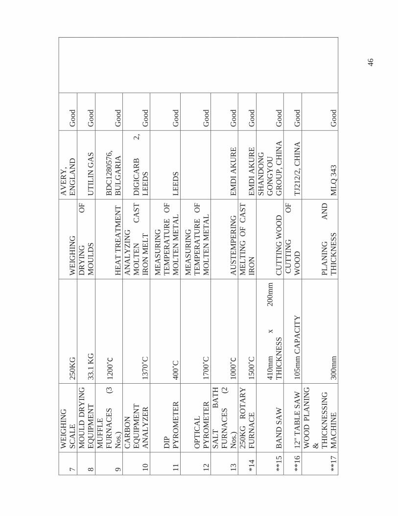
46
7 W
EIG
HIN
G
SCA
LE
250K
G
WEI
GH
ING
A
VER
Y,
ENG
LAN
D
Goo
d
8 M
OU
LD D
RY
ING
EQ
UIP
MEN
T 33
.1 K
G
DR
YIN
G
O
F M
OU
LDS
UTI
LIN
GA
S G
ood
9
MU
FFLE
FU
RN
AC
ES
(3
Nos
.) 12
00H
EAT
TREA
TMEN
T B
DC
1280
576,
B
ULG
AR
IA
Goo
d
10
CA
RB
ON
EQ
UIP
MEN
T A
NA
LYZE
R
1370
C
AN
ALY
ZIN
G
MO
LTEN
C
AST
IR
ON
MEL
T
DIG
ICA
RB
2,
LE
EDS
Goo
d
11
DIP
PY
RO
MET
ER
400
C
MEA
SUR
ING
TE
MPE
RA
TUR
E O
F M
OLT
EN M
ETA
L LE
EDS
Goo
d
12
OPT
ICA
L PY
RO
MET
ER
1700
C
MEA
SUR
ING
TE
MPE
RA
TUR
E O
F M
OLT
EN M
ETA
L
Goo
d
13
SALT
B
ATH
FU
RN
AC
ES
(2
Nos
.) 10
00A
UST
EMPE
RIN
G
EMD
I AK
UR
E G
ood
*14
250K
G
RO
TAR
Y
FUR
NA
CE
1500
C
MEL
TIN
G O
F C
AST
IR
ON
EM
DI A
KU
RE
Goo
d
**15
BA
ND
SA
W
410m
m
x 20
0mm
TH
ICK
NES
S C
UTT
ING
WO
OD
SHA
ND
ON
G
GO
NG
YO
U
GR
OU
P, C
HIN
A
Goo
d
**16
12" T
AB
LE S
AW
10
5mm
CA
PAC
ITY
C
UTT
ING
O
F W
OO
D
TJ21
2/2,
CH
INA
G
ood
**17
WO
OD
PLA
NIN
G
&
THIC
KN
ESSI
NG
M
AC
HIN
E 30
0mm
PL
AN
ING
A
ND
TH
ICK
NES
S M
LQ 3
43
Goo
d
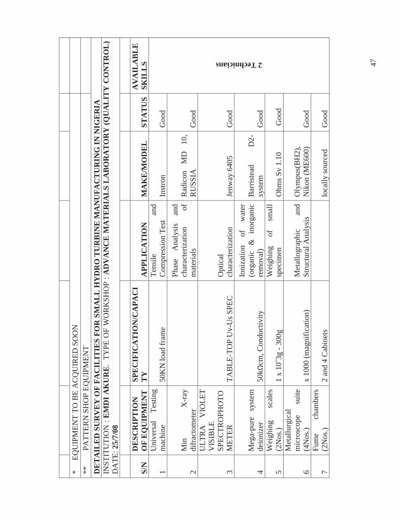
47
*
E
QU
IPM
ENT
TO B
E A
CQ
UIR
ED S
OO
N
**
P
ATT
ERN
SH
OP
EQU
IPM
ENT
DE
TA
ILE
D S
UR
VE
Y O
F FA
CIL
ITIE
S FO
R S
MA
LL
HY
DR
O T
UR
BIN
E M
AN
UFA
CT
UR
ING
IN N
IGE
RIA
IN
STIT
UTI
ON
:E
MD
I A
KU
RE
. TY
PE O
F W
OR
KSH
OP
: AD
VA
NC
E M
AT
ER
IAL
S L
AB
OR
AT
OR
Y (Q
UA
LIT
Y C
ON
TR
OL
) D
ATE
: 25/
7/08
S/N
D
ESC
RIP
TIO
N
OF
EQ
UIP
ME
NT
SP
EC
IFIC
AT
ION
/CA
PAC
IT
Y
APP
LIC
AT
ION
M
AK
E/M
OD
EL
ST
AT
US
AV
AIL
AB
LE
SK
ILL
S
1 U
nive
rsal
Te
stin
g m
achi
ne
50K
N lo
ad fr
ame
Tens
ile
and
Com
pres
sion
Tes
t In
stro
n G
ood
2 Technicians
2 M
in
X-r
ay
difr
acto
met
er
Phas
e A
naly
sis
and
char
acte
rizat
ion
of
mat
eria
ls
Rad
icon
M
D
10,
RU
SSIA
G
ood
3
ULT
RA
V
IOLE
T V
ISIB
LE
SPEC
TRO
PHO
TOM
ETER
TA
BLE
-TO
P U
v-U
s SPE
C
Opt
ical
ch
arac
teriz
atio
n Je
nway
640
5 G
ood
4 M
ega-
pure
sy
stem
de
ioni
zer
50k
cm, C
ondu
ctiv
ity
Ioni
zatio
n of
w
ater
(o
rgan
ic
&
inor
gani
c re
mov
al)
Bar
riste
ad
D2-
syst
em
Goo
d
5 W
eigh
ing
scal
es
(2N
os.)
1 x
103g
- 30
0g
Wei
ghin
g of
sm
all
spec
imen
O
hms S
v 1.
10
Goo
d
6
Met
allu
rgic
al
mic
rosc
ope
suite
(4
Nos
.) x
1000
(mag
nific
atio
n)
Met
allo
grap
hic
and
Stru
ctur
al A
naly
sis
Oly
mpu
s(B
H2)
, N
ikon
(ME6
00)
Goo
d
7 Fu
me
cham
bers
(2
Nos
.) 2
and
4 C
abin
ets
lo
cally
sour
ced
Goo
d
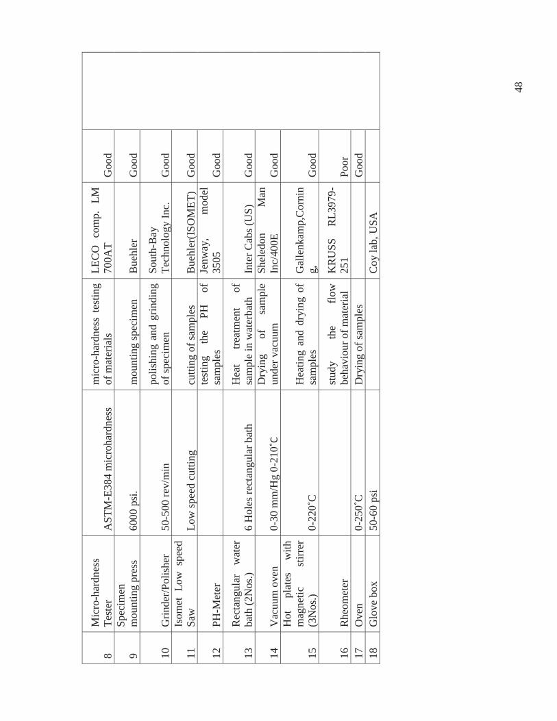
48
8 M
icro
-har
dnes
s Te
ster
A
STM
-E38
4 m
icro
hard
ness
m
icro
-har
dnes
s te
stin
g of
mat
eria
ls
LEC
O
com
p.
LM
700A
T G
ood
9 Sp
ecim
en
mou
ntin
g pr
ess
6000
psi
. m
ount
ing
spec
imen
B
uehl
er
Goo
d
10
Grin
der/P
olis
her
50-5
00 re
v/m
in
polis
hing
and
grin
ding
of
spec
imen
So
uth-
Bay
Te
chno
logy
Inc.
G
ood
11
Isom
et L
ow s
peed
Sa
w
Low
spee
d cu
tting
cu
tting
of s
ampl
es
Bue
hler
(ISO
MET
) G
ood
12
PH-M
eter
test
ing
the
PH
of
sam
ples
Je
nway
, m
odel
35
05
Goo
d
13
Rec
tang
ular
w
ater
ba
th (2
Nos
.) 6
Hol
es re
ctan
gula
r bat
h H
eat
treat
men
t of
sa
mpl
e in
wat
erba
th
Inte
r Cab
s (U
S)
Goo
d
14
Vac
uum
ove
n 0-
30 m
m/H
g 0-
210
Dry
ing
of
sam
ple
unde
r vac
uum
Sh
eled
on
Man
In
c/40
0E
Goo
d
15
Hot
pl
ates
w
ith
mag
netic
st
irrer
(3
Nos
.) 0-
220
C
Hea
ting
and
dryi
ng o
f sa
mpl
es
Gal
lenk
amp,
Cor
nin
g,
Goo
d
16
Rhe
omet
er
st
udy
the
flow
be
havi
our o
f mat
eria
l K
RU
SS
RL3
979-
251
Poor
17
O
ven
0-25
0C
D
ryin
g of
sam
ples
Goo
d 18
G
love
box
50
-60
psi
C
oy la
b, U
SA
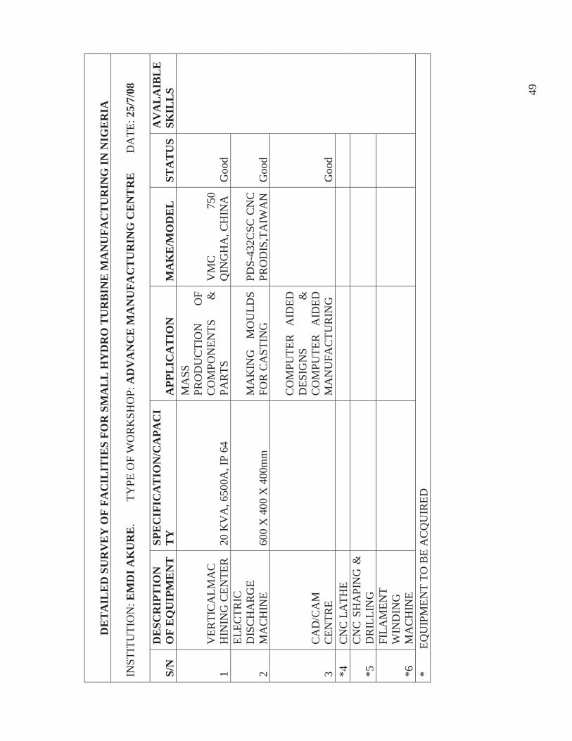
49
DE
TA
ILE
D S
UR
VE
Y O
F FA
CIL
ITIE
S FO
R S
MA
LL
HY
DR
O T
UR
BIN
E M
AN
UFA
CT
UR
ING
IN N
IGE
RIA
INST
ITU
TIO
N: E
MD
I AK
UR
E.
TYPE
OF
WO
RK
SHO
P: A
DV
AN
CE
MA
NU
FAC
TU
RIN
G C
EN
TR
E
D
ATE
: 25/
7/08
S/N
D
ESC
RIP
TIO
N
OF
EQ
UIP
ME
NT
SP
EC
IFIC
AT
ION
/CA
PAC
IT
Y
APP
LIC
AT
ION
M
AK
E/M
OD
EL
ST
AT
US
AV
AL
AIB
LE
SK
ILL
S
1 V
ERTI
CA
LMA
CH
ININ
G C
ENTE
R
20 K
VA
, 650
0A, I
P 64
MA
SS
PRO
DU
CTI
ON
O
F C
OM
PON
ENTS
&
PA
RTS
V
MC
75
0 Q
ING
HA
, CH
INA
G
ood
2
ELEC
TRIC
D
ISC
HA
RG
E M
AC
HIN
E 60
0 X
400
X 4
00m
m
MA
KIN
G
MO
ULD
S FO
R C
AST
ING
PD
S-43
2CSC
CN
C
PRO
DIS
,TA
IWA
NG
ood
3 C
AD
/CA
M
CEN
TRE
CO
MPU
TER
A
IDED
D
ESIG
NS
&
CO
MPU
TER
A
IDED
M
AN
UFA
CTU
RIN
G
G
ood
*4
CN
C L
ATH
E
*5
CN
C S
HA
PIN
G &
D
RIL
LIN
G
*6
FILA
MEN
T W
IND
ING
M
AC
HIN
E
*
EQ
UIP
MEN
T TO
BE
AC
QU
IRED
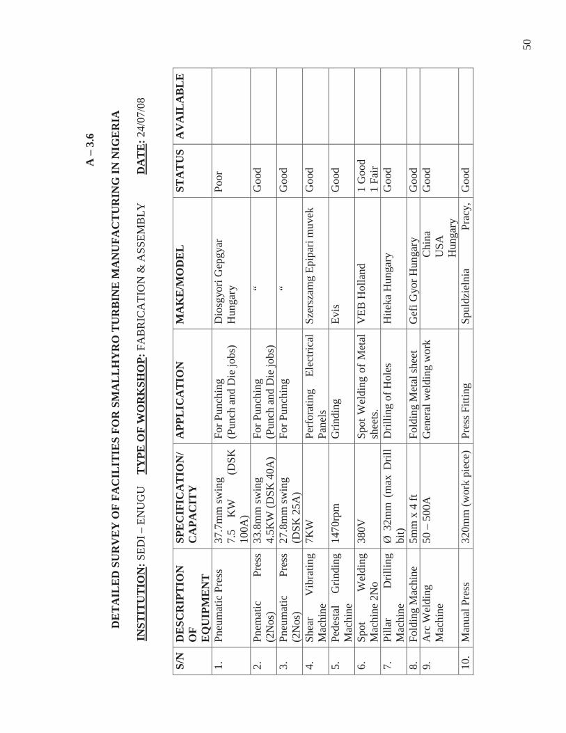
50
A –
3.6
DE
TA
ILE
D S
UR
VE
Y O
F FA
CIL
ITIE
S FO
R S
MA
LL
HY
RO
TU
RB
INE
MA
NU
FAC
TU
RIN
G IN
NIG
ER
IA
INST
ITU
TIO
N: S
EDI –
EN
UG
U
TY
PE O
F W
OR
KSH
OP:
FA
BR
ICA
TIO
N &
ASS
EMB
LY
DA
TE
: 24/
07/0
8
S/N
DE
SCR
IPT
ION
O
F
EQ
UIP
ME
NT
SPE
CIF
ICA
TIO
N/
CA
PAC
ITY
A
PPL
ICA
TIO
N
MA
KE
/MO
DE
L
STA
TU
SA
VA
ILA
BL
E
1.
Pneu
mat
ic P
ress
37
.7m
m sw
ing
7.5
KW
(DSK
10
0A)
For P
unch
ing
(Pun
ch a
nd D
ie jo
bs)
Dio
sgyo
ri G
epgy
ar
Hun
gary
Po
or
2.
Pnem
atic
Pr
ess
(2N
os)
33.8
mm
swin
g
4.5K
W (D
SK 4
0A)
For P
unch
ing
(P
unch
and
Die
jobs
)
“
Goo
d
3.
Pneu
mat
ic
Pres
s (2
Nos
) 27
.8m
m sw
ing
(DSK
25A
) Fo
r Pun
chin
g
“
Goo
d
4.
Shea
r V
ibra
ting
Mac
hine
7K
W
Perf
orat
ing
Elec
trica
l Pa
nels
Sz
ersz
amg
Epip
ari m
uvek
G
ood
5.
Pede
stal
G
rindi
ng
Mac
hine
14
70rp
m
Grin
ding
Ev
is
Goo
d
6.
Spot
W
eldi
ng
Mac
hine
2N
o 38
0V
Spot
Wel
ding
of
Met
al
shee
ts.
VEB
Hol
land
1
Goo
d 1
Fair
7.
Pilla
r D
rillin
g M
achi
ne
Ø 3
2mm
(m
ax D
rill
bit)
Dril
ling
of H
oles
H
iteka
Hun
gary
G
ood
8.
Fold
ing
Mac
hine
5m
m x
4 ft
Fo
ldin
g M
etal
shee
t G
efi G
yor H
unga
ry
Goo
d
9.
Arc
Wel
ding
M
achi
ne
50 –
500
A
Gen
eral
wel
ding
wor
k C
hina
U
SA
Hun
gary
Goo
d
10.
Man
ual P
ress
32
0mm
(wor
k pi
ece)
Pr
ess F
ittin
g Sp
uldz
ieln
ia
Prac
y,
Goo
d
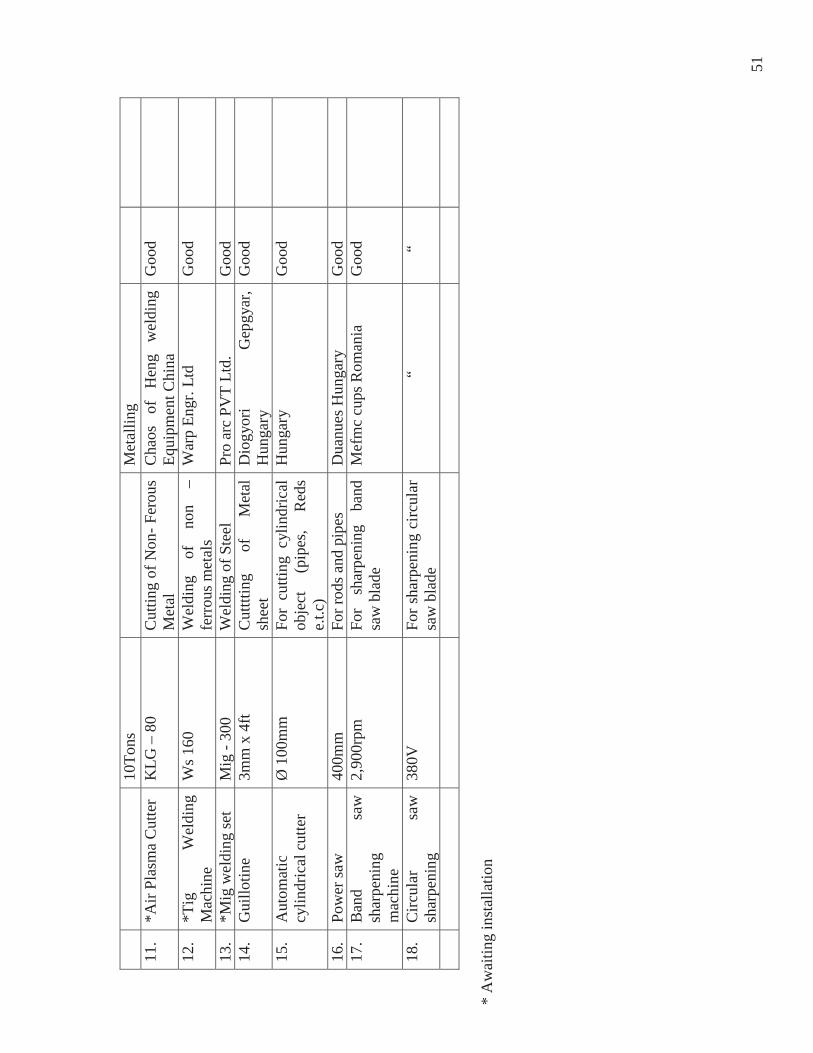
51
10To
ns
Met
allin
g 11
. *A
ir Pl
asm
a C
utte
r K
LG –
80
Cut
ting
of N
on- F
erou
s M
etal
C
haos
of
H
eng
wel
ding
Eq
uipm
ent C
hina
G
ood
12.
*Tig
W
eldi
ng
Mac
hine
W
s 160
W
eldi
ng
of
non
– fe
rrou
s met
als
War
p En
gr. L
td
Goo
d
13.
*Mig
wel
ding
set
Mig
- 30
0 W
eldi
ng o
f Ste
el
Pro
arc
PVT
Ltd.
G
ood
14
. G
uillo
tine
3mm
x 4
ft C
utttt
ing
of
Met
al
shee
t D
iogy
ori
Gep
gyar
, H
unga
ry
Goo
d
15.
Aut
omat
ic
cylin
dric
al c
utte
r Ø
100
mm
Fo
r cu
tting
cyl
indr
ical
ob
ject
(p
ipes
, R
eds
e.t.c
)
Hun
gary
G
ood
16.
Pow
er sa
w
400m
m
For r
ods a
nd p
ipes
D
uanu
es H
unga
ry
Goo
d
17.
Ban
d sa
w
shar
peni
ng
mac
hine
2,90
0rpm
Fo
r sh
arpe
ning
ba
nd
saw
bla
de
Mef
mc
cups
Rom
ania
G
ood
18.
Circ
ular
sa
w
shar
peni
ng
380V
Fo
r sha
rpen
ing
circ
ular
sa
w b
lade
“
“
* A
wai
ting
inst
alla
tion
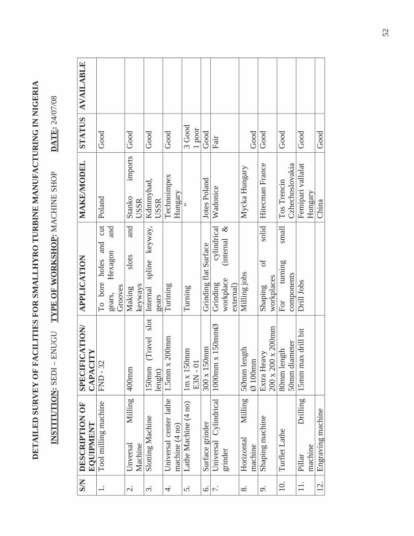
52
DE
TA
ILE
D S
UR
VE
Y O
F FA
CIL
ITIE
S FO
R S
MA
LL
HY
RO
TU
RB
INE
MA
NU
FAC
TU
RIN
G IN
NIG
ER
IA
INST
ITU
TIO
N: S
EDI –
EN
UG
U
TY
PE O
F W
OR
KSH
OP:
MA
CH
INE
SHO
P D
AT
E: 2
4/07
/08
S/N
DE
SCR
IPT
ION
OF
E
QU
IPM
EN
T
SPE
CIF
ICA
TIO
N/
CA
PAC
ITY
A
PPL
ICA
TIO
N
MA
KE
/MO
DE
L
STA
TU
SA
VA
ILA
BL
E
1.
Tool
mill
ing
mac
hine
FN
D -
32
To
bore
ho
les
and
cut
gear
s, H
exag
on
and
Gro
oves
Pola
nd
Goo
d
2.
Unv
ersa
l M
illin
g M
achi
ne
400m
m
Mak
ing
slot
s an
d ke
yway
s St
anko
im
ports
U
SSR
G
ood
3.
Slot
ting
Mac
hine
15
0mm
(T
rave
l sl
ot
leng
ht)
Inte
rnal
sp
line
keyw
ay,
gear
s K
dmm
yhad
, U
SSR
G
ood
4.
Uni
vers
al c
ente
r la
the
mac
hine
(4 n
o)
1.5m
m x
200
mm
Tu
rinin
g Te
chno
impe
x H
unga
ry
Goo
d
5.
Lath
e M
achi
ne (4
no)
1m
x 1
50m
m
E3N
- 01
Tu
rnin
g
“ 3
Goo
d 1
poor
6.
Su
rfac
e gr
inde
r 30
0 x
150m
m
Grin
ding
flat
Sur
face
Jo
tes P
olan
d G
ood
7.
U
nive
rsal
Cyl
indr
ical
gr
inde
r 10
00m
m x
150
mm
Ø
Grin
ding
cy
lindr
ical
w
orkp
lace
(inte
rnal
&
ex
tern
al)
Wad
onic
e Fa
ir
8.
Hor
izon
tal
Mill
ing
mac
hine
5Ø
mm
leng
th
Ø 1
00m
m
Mill
ing
jobs
M
ycka
Hun
gary
G
ood
9.
Shap
ing
mac
hine
Ex
tra H
eavy
20
0 x
200
x 20
0mm
Sh
apin
g of
so
lid
wor
kpla
ces
Hite
cman
Fra
nce
Goo
d
10.
Turf
let L
athe
80
mm
leng
th
50m
m d
iam
eter
Fo
r tu
rnin
g sm
all
com
pone
nts
Tos T
renc
in
Czh
echo
slov
akia
G
ood
11.
Pilla
r D
rillin
g m
achi
ne
15m
m m
ax d
rill b
it D
rill J
obs
Fem
ipar
i val
lala
t H
unga
ry
Goo
d
12.
Engr
avin
g m
achi
ne
Chi
na
Goo
d
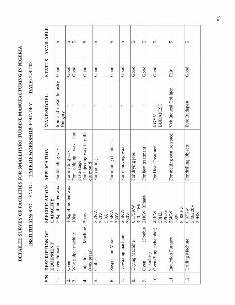
53
DE
TA
ILE
D S
UR
VE
Y O
F FA
CIL
ITIE
S FO
R S
MA
LL
HY
RO
TU
RB
INE
MA
NU
FAC
TU
RIN
G IN
NIG
ER
IA
INST
ITU
TIO
N: S
EDI –
EN
UG
U
TY
PE O
F W
OR
KSH
OP:
FO
UN
DR
Y
DA
TE
: 24/
07/0
8
S/N
DE
SCR
IPT
ION
OF
E
QU
IPM
EN
T
SPE
CIF
ICA
TIO
N/
CA
PAC
ITY
A
PPL
ICA
TIO
N
MA
KE
/MO
DE
L
STA
TU
SA
VA
ILA
BL
E
1.
Ove
n Fu
rnac
e 50
kg o
f mol
ten
wax
Fo
r ble
ndin
g w
ax
Iron
and
met
al I
ndus
try
Hun
gary
G
ood
5
2.
Ove
n 10
kg o
f mol
ten
wax
Fo
r mel
ting
wax
“
Goo
d
5
3.
Wax
pul
per m
achi
ne
10kg
Fo
r pu
lpin
g w
ax
into
pa
ste
stag
e
“
Goo
d
5
4.
Inje
ctio
n M
achi
ne
(wax
pre
ss)
5bar
s Fo
r inj
ectin
g w
ax in
to th
e di
e m
ould
“
Goo
d
5
5.
Chi
ller
3.7K
W
380V
5.
9A
For c
oolin
g
“
Goo
d
5
6.
Susp
ensi
on M
ixer
1.
5KW
38
0V
For m
inin
g ch
emic
als
“ G
ood
5
7.
Dew
axin
g m
achi
ne
2.5K
W
380V
Fo
r rem
ovin
g w
ax
“ G
ood
5
8.
Dry
ing
Mac
hine
0.
175K
W
440
– 1M
in
For d
ryin
g jo
bs
“ G
ood
5
9.
Ove
n (D
oubl
e C
ham
ber)
21
KW
, 3Ph
ase
For h
eat t
reat
men
t
“
Goo
d
5
10.
Ove
n (S
ingl
e ch
ambe
r)
42K
W
50H
Z 3P
hase
For H
eat T
reat
men
t K
GY
V
BU
DA
PEST
G
ood
5
11.
Indu
ctio
n Fu
rnac
e 56
KW
70
0v
8,00
0HZ
For m
eltin
g ca
st ir
on st
eel
Veb
Indu
cal G
ollig
en
Fair
5
12.
Dril
ling
Mac
hine
0.
37K
w
380/
220V
50
HZ
For d
rillin
g O
bjec
ts
Evic
Bud
apes
t G
ood
5
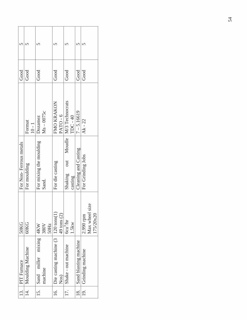
54
13.
PIT
Furn
ace
50K
G
For N
on- F
erro
us m
etal
s
Goo
d
5
14.
Mou
ldin
g M
achi
ne
60K
G
For m
ould
ing
Form
at
10 -
1 G
ood
5
15.
Sand
m
iller
m
ixin
g m
achi
ne
4KW
38
0V
50H
z
For m
ixin
g th
e m
ould
ing
Sa
nd.
Doz
amez
M
s – 0
075c
G
ood
5
16.
Die
cas
ting
mac
hine
(3
Nos
) 12
0 to
ns(1
) 49
tons
(2)
For d
ie c
astin
g FM
O K
RA
KO
N
PATO
- 6
Goo
d
5
17.
Shak
e - o
ut m
achi
ne
6cu3 /h
r 1.
5kw
Sh
akin
g ou
t M
oudl
e ca
stin
g
M/3
Tec
hnoc
rats
TD
C -
40
Goo
d
5
18.
Sand
bla
stin
g m
achi
ne
C
lean
ing
and
Cas
ting
7 –
5.16
619
Goo
d
5
19.
Grin
ding
mac
hine
2.
990
rpm
M
ax w
heel
size
17
5/20
x20
For G
rindi
ng Jo
bs
Ak
- 22
Goo
d
5
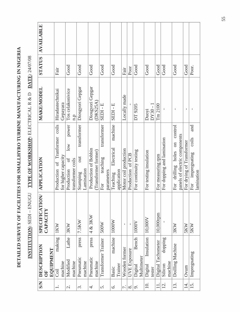
55
DE
TA
ILE
D S
UR
VE
Y O
F FA
CIL
ITIE
S FO
R S
MA
LL
HY
RO
TU
RB
INE
MA
NU
FAC
TU
RIN
G IN
NIG
ER
IA
INST
ITU
TIO
N: S
EDI –
EN
UG
U
TY
PE O
F W
OR
KSH
OP:
ELE
CTR
ICA
L R
& D
D
AT
E: 2
4/07
/08
S/N
DE
SCR
IPT
ION
O
F
EQ
UIP
ME
NT
SPE
CIF
ICA
TIO
N/
CA
PAC
ITY
A
PPL
ICA
TIO
N
MA
KE
/MO
DE
L
STA
TU
SA
VA
ILA
BL
E
1.
Coi
l m
akin
g m
achi
ne
1KW
Pr
oduc
tion
of
Tran
form
er
coils
fo
r hig
her c
apac
ity
Hira
dast
echn
ikai
G
epay
ara
Fair
2.
Mod
ified
La
the
mac
hine
3K
W
Prod
uctio
n of
lo
w
pow
er
trans
form
er c
oils
To
s cel
akon
ivic
e n.
p G
ood
3.
Pneu
mat
ic
pres
s m
achi
ne
7.5K
W
Stam
ping
ou
t tra
nsfo
rmer
La
min
atio
n D
iosg
yori
Gep
gar
Goo
d
4.
Pneu
mat
ic
pres
s m
achi
ne
4 &
3K
W
Pro
duct
ion
of B
obbi
n (T
rans
form
er fo
rmer
) D
iosg
yori
Gep
gar
(DK
S25A
) G
ood
5.
Tran
sfor
mer
Tra
iner
50
0W
For
teac
hing
tra
nsfo
rmer
pa
ram
eter
s SE
DI -
E
Goo
d
6.
Bas
ic
mac
hine
Tr
aine
r 10
00W
Te
achi
ng
Elec
trica
l m
achi
ne
appl
icat
ion
SED
I - E
G
ood
7.
Woo
den
form
er
- M
otor
coi
l pro
duct
ion
Lo
cally
mad
e
Fair
8.
U
VE
Expo
sure
-
Prod
uctio
n o
f PC
B
- Po
or
9.
D
igita
l B
ench
M
ultim
eter
10
00V
Fo
r con
tinui
ty te
stin
g D
T 92
05
Goo
d
10.
Dig
ital
Insu
latio
n te
ster
10
,000
V
For t
estin
g in
sula
tion
Duo
yi
DY
30 -
1 G
ood
11.
Dig
ital T
acho
met
er
10,0
00rp
m
For m
easu
ring
rpm
Tm
210
0 G
ood
12
. Si
licon
do
ppin
g m
achi
ne
-
For d
oppi
ng a
nd la
min
atio
n
- G
ood
13.
Doi
lling
Mac
hine
3K
W
For
drill
ing
hole
s on
co
ntro
l pa
nels
of e
lect
ric c
ompo
nent
s
- G
ood
14.
Ovu
m
5KW
Fo
r dry
ing
of T
rans
form
er
-
Goo
d
15.
Impr
egna
ting
5KW
Fo
r im
preg
natin
g co
ils
and
lam
inat
ion
-
Poor
.

56
A – 3.7
NATIONAL AGENCY FOR SCIENCE AND ENGINEERING INFRASTRUCTURE (NASENI)
Location: Idu, Industrial Area, Abuja
Postal Address: NASENI Federal Ministry of Science & Technology Idu, Industrial Area P.M.B. 391 Garki, Abuja.
Overseeing Ministry: Federal Ministry of Science and Technology, Abuja
Mandate/Activities: Specifically in the area of capital goods, research, production, and reverse engineering with respect to broad areas:
Engineering materials Engineering Equipment; Mechanical, Hydraulic, Pneumatic etc. Engineering Designs and Standardization. Power Equipment: Generation, Transmission, Distribution, Prime movers; Mechanical.
4.1 Mission: To establish and nurture an appropriate, dynamic and Engineering Infrastructure base for achieving home – initiated and home sustaining industrialization through the development of relevant process, capital goods and equipment, necessary for job creation, national economic well being and progress.
4.2 Vision: To create an enabling knowledge – driven environment for local mass – production of standard parts, goods and services, required for the Nation’s Technological advancement.
4.3 Target: Small and Medium Scale industries, through the impartation of technologies, engineering principles and practices for the production of equipment that will meet international standards as well as flourish local capital goods industry.
Management Structure: In pursuant of its mandate, the Agency operates through 7 development institutes: -
Science Equipment Development Institute – SEDI, Enugu. SEDI, Minna
Electronics Development Institute – ELDI, Awka

57
Hydraulic Equipment Development Institute HEDI, Kano
Engineering Materials Development Institute EMDI, Akure.
National Engineering Design Development Institute NEDDI, Nnewi
Power Equipment and Electrical Machines Development Institute- PEEMADI, Okene.
7.0 Human capacity: NASENI Head Quarters has engineers trained in the field of Small Hydro POWER Technology. One was trained in China in 2006; two others will conclude their training in June 2008. Also available is a pool of engineers trained in the use of CAD software such as: Autodesk, Solid Works, Pro-Engineer; Modeling and Simulation software such as Mat lab, COM sol, Hysys, Granary Design, Ansys.
NASENI is adopting the process of Reverse Engineering for the Turbine project in collaboration with identified stakeholders and some Nigerian Higher Institutions with relevant competences.
NASENI has the human and material capacity to implement the Turbine Fabrication project as follows:
Over 70 graduate engineers Over 5 PhD engineers Over 30 M Sc. Over 50 Scientist Over 100 technologist, technicians Over 100 craftsmen and artisan Over 100 Research fellows A mandate to source for and utilize experts in any discipline and from anywhere Work with a lot of universities in the implementation of some projects. Sponsor some research and development projects in tertiary institutions and R & D Institute.
8.0 Workshop Facilities: All the Development Institute are equipped with the typical AMC as the following:
Mini – foundries Mechanical workshops Advanced Manufacturing centre (AMC)
9.0 Equipment List: A list of newly acquired equipment and machinery for the development institutes are
shown in A.3 -2 i. Vertical Milling Machine
ii. CNC Lathe iii. Surface Grinder iv. Electric Discharge Machine (EDM) v. Rotary furnace
58
vi. Induction furnace vii. Pattern shop.
10.0 NASENI INITIATIVE IN SMALL HYDRO POWER EQUIPMENT MANUFACTURING
10.1 Scope In the long term, the Agency is working towards the establishment of a Small Hydro Power Machinery and Equipment Development Institute and a Manufacturing Industry to go along with it. However, in the short term, the Agency is adopting a model which will lead to quick harvest of “low-hanging fruits” to show that it is do-able. Knowing that the “heart” of a Small Hydro Power project is the turbine, a domestically made Small Hydro turbine will therefore “leap-frog” the process of rural electrification and ultimately bring down the per kilowatt installation cost of Small Hydro Power plants. Hence, NASENI’s current focus on the local fabrication of small hydro turbine with capacity ranging between 70 and 100KW.
10.2 Methodology The Agency is adopting the process of Reverse Engineering for this project in collaboration with identified stakeholders and some Nigerian Higher Institution with relevant competencies.
10.3 Capacity to run the Proposed Project
10.3.1 Experience (Skills) Garnered from Past and On-going Projects
NASENI has successfully used the reverse engineering method to develop the local fabrication of the Seed Oil Expeller. Also, the Agency’s Collaborative efforts in R & D with some universities have yielded result on the design and production of cassava flour processing plant project.
1.0 The Seed Oil Expeller This is one of our flagship products in the concept of Reverse Engineering. The Agency acquired a seed oil expeller with the aim of replicating it and developing the requisite skills for its mass production. Currently, the Agency has successfully replicated it; the prototype seed oil expeller is available. The working drawings in 2D and 3D AutoCAD designs are also available.
The machine was fabricated, assembled and in perfect working condition. Oil from groundnut and palm kernel have been produced. Work is also on-going on the production of the manufacturing layout which will be published and made available to Small and Medium Enterprises (SMEs) who will be involved in proliferation of the machine. NASENI has shown that this is do-able.
2.0 Integrated Cassava Flour Processing
The project is still on-going and was aimed at designing and manufacturing a prototype cassava/yam processing plant with a capacity up to 2.5tons per day, and providing the technological environment for the private sector to produce high quality cassava and yam flour and the local manufacturing of the processing plant. The Project is run in

59
collaboration with five Universities with core competences in various equipment that make up the production line. These are:
Abubakar Tafawa Balewa University, Bauchi (ATBU) Federal University of Technology, Minna (FUTM) Federal University of Technology, Owerri (FUTO) Federal University of Technology, Akure (FUTA); andObafemi Awolowo University, Ile Ife, (OAU).
All the component machines of the processing plant have been produced and tested. The remaining phases of the project include the integration and instrumentation of the component machines and then commissioning. Thereafter, an investors’ forum will be organized in order to cede it to a private firm interested in mass producing the processing plant.
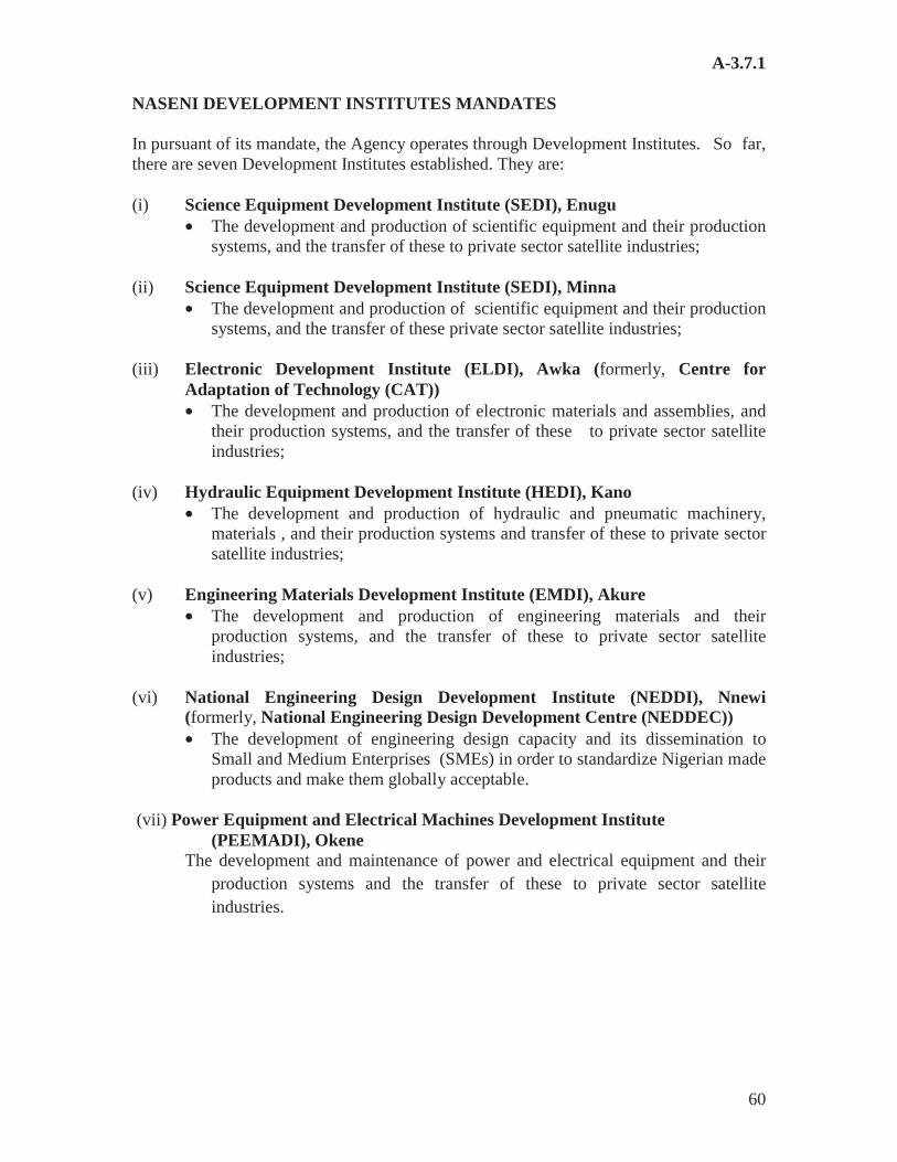
60
A-3.7.1
NASENI DEVELOPMENT INSTITUTES MANDATES
In pursuant of its mandate, the Agency operates through Development Institutes. So far, there are seven Development Institutes established. They are:
(i) Science Equipment Development Institute (SEDI), Enugu • The development and production of scientific equipment and their production
systems, and the transfer of these to private sector satellite industries;
(ii) Science Equipment Development Institute (SEDI), Minna • The development and production of scientific equipment and their production
systems, and the transfer of these private sector satellite industries;
(iii) Electronic Development Institute (ELDI), Awka (formerly, Centre for Adaptation of Technology (CAT)) • The development and production of electronic materials and assemblies, and
their production systems, and the transfer of these to private sector satellite industries;
(iv) Hydraulic Equipment Development Institute (HEDI), Kano • The development and production of hydraulic and pneumatic machinery,
materials , and their production systems and transfer of these to private sector satellite industries;
(v) Engineering Materials Development Institute (EMDI), Akure • The development and production of engineering materials and their
production systems, and the transfer of these to private sector satellite industries;
(vi) National Engineering Design Development Institute (NEDDI), Nnewi (formerly, National Engineering Design Development Centre (NEDDEC)) • The development of engineering design capacity and its dissemination to
Small and Medium Enterprises (SMEs) in order to standardize Nigerian made products and make them globally acceptable.
(vii) Power Equipment and Electrical Machines Development Institute (PEEMADI), Okene
The development and maintenance of power and electrical equipment and their production systems and the transfer of these to private sector satellite industries.
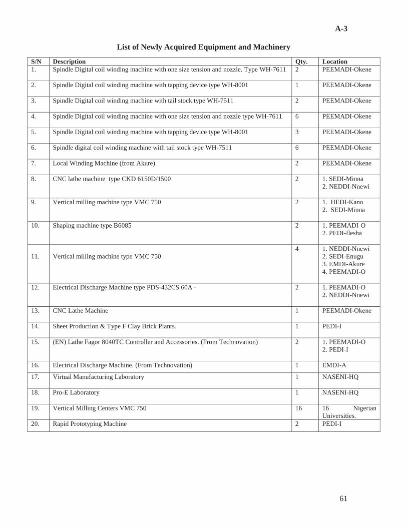
61
A-3
List of Newly Acquired Equipment and Machinery
S/N Description Qty. Location 1. Spindle Digital coil winding machine with one size tension and nozzle. Type WH-7611 2 PEEMADI-Okene
2. Spindle Digital coil winding machine with tapping device type WH-8001 1 PEEMADI-Okene
3. Spindle Digital coil winding machine with tail stock type WH-7511 2 PEEMADI-Okene
4. Spindle Digital coil winding machine with one size tension and nozzle type WH-7611 6 PEEMADI-Okene
5. Spindle Digital coil winding machine with tapping device type WH-8001 3 PEEMADI-Okene
6. Spindle digital coil winding machine with tail stock type WH-7511 6 PEEMADI-Okene
7. Local Winding Machine (from Akure) 2 PEEMADI-Okene
8. CNC lathe machine type CKD 6150D/1500 2 1. SEDI-Minna 2. NEDDI-Nnewi
9. Vertical milling machine type VMC 750 2 1. HEDI-Kano 2. SEDI-Minna
10. Shaping machine type B6085 2 1. PEEMADI-O 2. PEDI-Ilesha
11. Vertical milling machine type VMC 750
4 1. NEDDI-Nnewi 2. SEDI-Enugu 3. EMDI-Akure 4. PEEMADI-O
12. Electrical Discharge Machine type PDS-432CS 60A - 2 1. PEEMADI-O 2. NEDDI-Nnewi
13. CNC Lathe Machine 1 PEEMADI-Okene
14. Sheet Production & Type F Clay Brick Plants. 1 PEDI-I
15. (EN) Lathe Fagor 8040TC Controller and Accessories. (From Technovation) 2 1. PEEMADI-O 2. PEDI-I
16. Electrical Discharge Machine. (From Technovation) 1 EMDI-A
17. Virtual Manufacturing Laboratory 1 NASENI-HQ
18. Pro-E Laboratory 1 NASENI-HQ
19. Vertical Milling Centers VMC 750 16 16 Nigerian Universities.
20. Rapid Prototyping Machine 2 PEDI-I
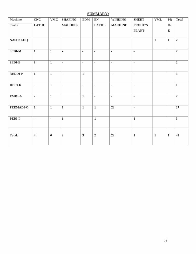
62
SUMMARY: Machine CNC
LATHE
VMC SHAPING
MACHINE
EDM EN
LATHE
WINDING
MACHINE
SHEET
PRODT’N
PLANT
VML PR
O-
E
Total
Centre
NASENI-HQ 1 1 2
SEDI-M 1 1 - - - - - 2
SEDI-E 1 1 - - - - - 2
NEDDI-N 1 1 - 1 - - - 3
HEDI-K - 1 - - - - - 1
EMDI-A - 1 1 - - - 2
PEEMADI-O 1 1 1 1 1 22 - 27
PEDI-I - - 1 1 1 3
Total: 4 6 2 3 2 22 1 1 1 42

63
Note to the Accounts
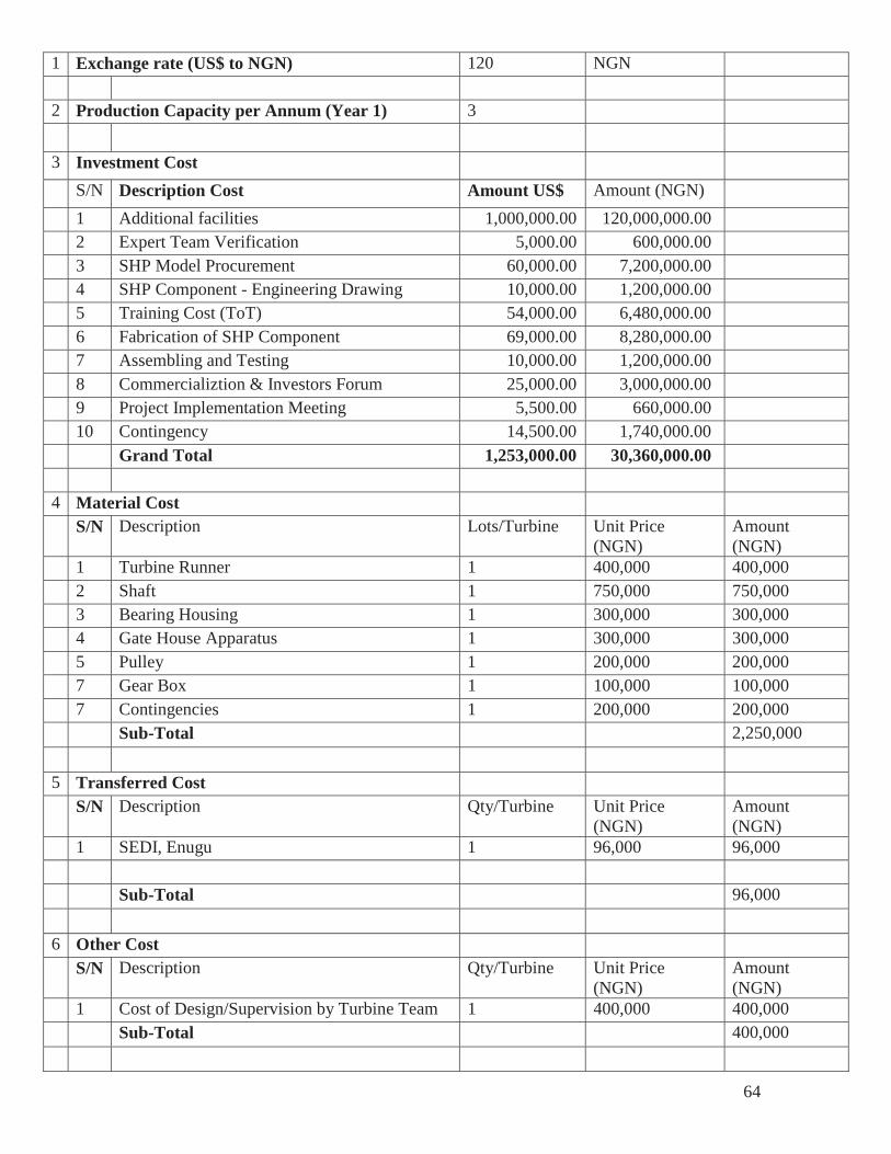
64
1 Exchange rate (US$ to NGN) 120 NGN
2 Production Capacity per Annum (Year 1) 3 3 Investment Cost S/N Description Cost Amount US$ Amount (NGN) 1 Additional facilities 1,000,000.00 120,000,000.00 2 Expert Team Verification 5,000.00 600,000.00 3 SHP Model Procurement 60,000.00 7,200,000.00 4 SHP Component - Engineering Drawing 10,000.00 1,200,000.00 5 Training Cost (ToT) 54,000.00 6,480,000.00 6 Fabrication of SHP Component 69,000.00 8,280,000.00 7 Assembling and Testing 10,000.00 1,200,000.00 8 Commercializtion & Investors Forum 25,000.00 3,000,000.00 9 Project Implementation Meeting 5,500.00 660,000.00 10 Contingency 14,500.00 1,740,000.00 Grand Total 1,253,000.00 30,360,000.00 4 Material Cost
S/N Description Lots/Turbine Unit Price (NGN)
Amount (NGN)
1 Turbine Runner 1 400,000 400,000 2 Shaft 1 750,000 750,000 3 Bearing Housing 1 300,000 300,000 4 Gate House Apparatus 1 300,000 300,000 5 Pulley 1 200,000 200,000 7 Gear Box 1 100,000 100,000 7 Contingencies 1 200,000 200,000 Sub-Total 2,250,000 5 Transferred Cost
S/N Description Qty/Turbine Unit Price (NGN)
Amount (NGN)
1 SEDI, Enugu 1 96,000 96,000 Sub-Total 96,000 6 Other Cost
S/N Description Qty/Turbine Unit Price (NGN)
Amount (NGN)
1 Cost of Design/Supervision by Turbine Team 1 400,000 400,000 Sub-Total 400,000
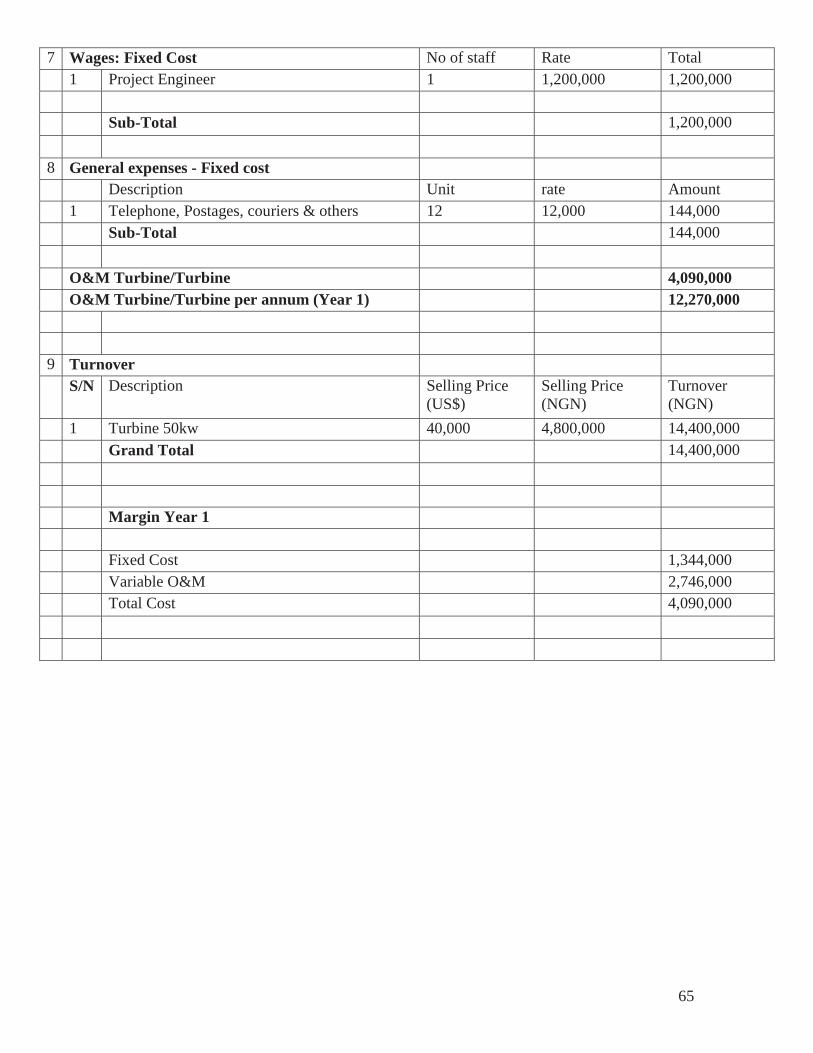
65
7 Wages: Fixed Cost No of staff Rate Total 1 Project Engineer 1 1,200,000 1,200,000 Sub-Total 1,200,000 8 General expenses - Fixed cost Description Unit rate Amount 1 Telephone, Postages, couriers & others 12 12,000 144,000 Sub-Total 144,000
O&M Turbine/Turbine 4,090,000 O&M Turbine/Turbine per annum (Year 1) 12,270,000
9 Turnover S/N Description Selling Price
(US$) Selling Price (NGN)
Turnover (NGN)
1 Turbine 50kw 40,000 4,800,000 14,400,000 Grand Total 14,400,000 Margin Year 1 Fixed Cost 1,344,000 Variable O&M 2,746,000 Total Cost 4,090,000