Embed Size (px)
Citation preview
INOM EXAMENSARBETE ELEKTROTEKNIK,AVANCERAD NIVÅ, 30 HP
, STOCKHOLM SVERIGE 2018
Feasibility Study for Substation Communication using Parallel Redundant Wireless Technology
NEHA KUMARI
KTHSKOLAN FÖR ELEKTROTEKNIK OCH DATAVETENSKAP

Abstract
Substations are an integral part of electric energy transmission and distributionsystem. With the evolution of conventional substations as digital substations,and in parallel, with the revolutionized emergence of communication systems,new communication schemes are being designed and retrofitted to incorporatethe data from relays, circuit breakers and Intelligent Electronic Devices (IEDs)to integrate with the new digital substations.
The thesis thus aims in evaluating a few wireless technologies to address theavailability and reliability at the process level of Digital Substation System. Itis achieved by introducing a redundant wireless network in parallel to existingwired solutions. For the purpose three wireless technologies IEEE 802.11g andStandalone 4G LTE network Base Station (BS) have been evaluated experi-mentally in a laboratory environment and 5G has been evaluated in a softwaresimulated environment.
The experimental results corresponding to IEEE 802.11g and 4G had theirown limitations and faced a few challenges in meeting the process level SampledValue data requirements. Whereas 5G showed a positive result in most of thescenarios, meeting the process bus requirement in terms of latency and packetloss.
iii

v
SammanfattningSubstationer r en integrerad del av elenergiverfrings- och distributionssystemet.Med utvecklingen av konventionella transformatorer som digitala substationeroch parallellt med den revolutionerade framkomsten av kommunikationssystem,r nya kommunikationssystem utformade och eftermonterade fr att integrera datafrn reler, strmbrytare och intelligenta elektroniska enheter (IED) fr att integreramed nya digitala transformatorer.
Avhandlingen syftar sledes till att utvrdera ngra trdlsa tekniker fr att till-godose tillgngligheten och tillfrlitligheten p processniv fr digitala substationer.Det uppns genom att infra ett redundant trdlst ntverk parallellt med befintligakablade lsningar. Fr det ndamlet har tre trdlsa tekniker IEEE 802.11g och Stan-dalone 4G LTE-ntverksbasen (BS) utvrderats experimentellt i en laboratoriemiljoch 5G har utvrderats i en mjukvarusimulerad milj.
De experimentella resultaten som motsvarade IEEE 802.11g och 4G hadesina egna begrnsningar och mtte ngra utmaningar fr att uppfylla processnivernafr samplingsvrde fr samplingsvrde. Medan 5G visade ett positivt resultat i deflesta scenarierna, uppfyllde processbusskravet avseende latens och paketfrlust.

Acknowledgements
It is with great pleasure that I would like to express my gratitude to each andeveryone who has been part of my journey towards completion of my Thesis.
Starting, I would like to express my sincere gratitude towards Dr SubratKumar Sahoo for giving me an opportunity to work under him at ABB and su-pervising me at each and every step and helping me out at so many road-blockersthat we faced during the project. I would like to thank Robert Saers for support-ing the project in all possible ways that he could. A sincere thanks to NilangaAbeywickrama for following my progress and for providing relevant guidance.Thanks to all the members of the service desk at ABB who helped with the labequipments, software installations and helping with my computer issues most ofthe time. Thanks to Jonas Neander, Krister Landernas, Luka Lednicki, Morgan,Johan Salj for being there to help and guide in the project whenever approached.Thanks to a group of people at Ericsson, Fedor Chernogorov, Gustav Wikstrm,Ikram Ashraf, Johan Torsner, Johan Kronander and Osama Al-Saadeh for fre-quent skype meeting and updates and guiding us at our doubts. A huge thanksto thanks to Ben Slimane and Ki Won Sung for accepting me as a Thesis studentunder them and cooperating all along with the updates, meetings, seminars andproviding with the academic support at KTH.
Last but not the least thanks to my god like parents and my lovable siblingsfor providing me with the emotional support even from far.
vii

Contents
1 Introduction 11.1 Background . . . . . . . . . . . . . . . . . . . . . . . . . . . . . . 31.2 Motivation . . . . . . . . . . . . . . . . . . . . . . . . . . . . . . 41.3 Outline . . . . . . . . . . . . . . . . . . . . . . . . . . . . . . . . 5
2 Problem Formulation 72.1 Purpose . . . . . . . . . . . . . . . . . . . . . . . . . . . . . . . . 72.2 Problem Statement . . . . . . . . . . . . . . . . . . . . . . . . . . 72.3 Research Question . . . . . . . . . . . . . . . . . . . . . . . . . . 82.4 Goal and Objective . . . . . . . . . . . . . . . . . . . . . . . . . . 92.5 Important aspects of adopting wireless technology in Power system 9
2.5.1 Ethics . . . . . . . . . . . . . . . . . . . . . . . . . . . . . 92.5.2 Sustainability . . . . . . . . . . . . . . . . . . . . . . . . . 92.5.3 Benefits . . . . . . . . . . . . . . . . . . . . . . . . . . . . 10
2.6 Related work and Methodology . . . . . . . . . . . . . . . . . . . 102.7 Delimitations . . . . . . . . . . . . . . . . . . . . . . . . . . . . . 11
3 IEC 61850 Enabled Digital Substation 133.1 Constituents of Digital substation . . . . . . . . . . . . . . . . . . 133.2 Advantages . . . . . . . . . . . . . . . . . . . . . . . . . . . . . . 153.3 Key features . . . . . . . . . . . . . . . . . . . . . . . . . . . . . . 173.4 Substation requirements . . . . . . . . . . . . . . . . . . . . . . . 17
3.4.1 General requirements . . . . . . . . . . . . . . . . . . . . 173.4.2 Operational requirements . . . . . . . . . . . . . . . . . . 183.4.3 Communication model and services . . . . . . . . . . . . . 183.4.4 Communication requirements . . . . . . . . . . . . . . . . 20
4 Overview of Wireless communication 234.1 A technical evolution . . . . . . . . . . . . . . . . . . . . . . . . . 234.2 Wifi technology . . . . . . . . . . . . . . . . . . . . . . . . . . . . 26
4.2.1 WLAN Standards . . . . . . . . . . . . . . . . . . . . . . 274.2.2 IEEE 802.11 Network Components and Architecture . . . 284.2.3 Layer description and framing . . . . . . . . . . . . . . . . 29
4.3 Technical overview of Long Term Evolution . . . . . . . . . . . . 304.3.1 Network components and architecture . . . . . . . . . . . 304.3.2 Protocol stack layers and framing . . . . . . . . . . . . . . 31
4.4 The fifth generation of mobile networks . . . . . . . . . . . . . . 334.4.1 Architecture . . . . . . . . . . . . . . . . . . . . . . . . . 34
ix
x Contents
4.4.2 Protocol Layer stacks . . . . . . . . . . . . . . . . . . . . 34
5 Methodology- Protocol stack communication model 375.1 Wired digital substation . . . . . . . . . . . . . . . . . . . . . . . 38
5.1.1 Physical layer . . . . . . . . . . . . . . . . . . . . . . . . . 385.1.2 Link layer . . . . . . . . . . . . . . . . . . . . . . . . . . . 385.1.3 Application layer . . . . . . . . . . . . . . . . . . . . . . . 38
5.2 IEC 61850 and IEEE.802.11 Integration scenario . . . . . . . . . 405.2.1 Protocol stack layers . . . . . . . . . . . . . . . . . . . . . 405.2.2 Experimental set-up . . . . . . . . . . . . . . . . . . . . . 40
5.3 IEC 61850 and 4G LTE integration scenario . . . . . . . . . . . . 415.3.1 Protocol stack layers . . . . . . . . . . . . . . . . . . . . . 425.3.2 Experimental set-up . . . . . . . . . . . . . . . . . . . . . 42
5.4 IEC 61850 and 5G integration scenario . . . . . . . . . . . . . . . 445.4.1 Protocol layers communication . . . . . . . . . . . . . . . 445.4.2 Simulation scenario inputs and data pre-requisites . . . . 445.4.3 Simulation assumptions . . . . . . . . . . . . . . . . . . . 46
6 Results and Discussion 516.1 IEEE 802.11 Performance evaluation on process bus . . . . . . . 516.2 4G LTE Network performance evaluation . . . . . . . . . . . . . 54
6.2.1 Scenario with 379 packets per second sent together . . . . 556.2.2 When the packets per second sent is 900 pps . . . . . . . 566.2.3 Scenario with varying packets per second sent over network 56
6.3 5G Network results . . . . . . . . . . . . . . . . . . . . . . . . . . 576.3.1 Digital substation in Interference Isolated scenario . . . . 576.3.2 Digital substation in Co-existence with eMBB traffic . . . 58
6.4 Discussion . . . . . . . . . . . . . . . . . . . . . . . . . . . . . . . 61
7 Conclusion and Future Scope 637.1 Conclusion . . . . . . . . . . . . . . . . . . . . . . . . . . . . . . 637.2 Future scope . . . . . . . . . . . . . . . . . . . . . . . . . . . . . 64
REFERENCES 67
List of Tables
3.1 Structure of the standard IEC 61850 . . . . . . . . . . . . . . . . 133.2 Interfaces involved and their functions [7] . . . . . . . . . . . . . 143.3 Classification of various types of messages based on performance
class and transfer time requirements [7] . . . . . . . . . . . . . . 20
4.1 Technical evolution in generations of wireless technology [18] . . 254.2 Technical comparison among various amendments of IEEE 802.11
standard [18] . . . . . . . . . . . . . . . . . . . . . . . . . . . . . 27
5.1 Simulation scenario description . . . . . . . . . . . . . . . . . . . 465.2 Data Traffic description . . . . . . . . . . . . . . . . . . . . . . . 465.3 Application characteristics . . . . . . . . . . . . . . . . . . . . . 475.4 Generic Configuration of different parameters used in simulation 475.5 URLCC Network antenna settings . . . . . . . . . . . . . . . . . 485.6 eMBB Interference characteristics . . . . . . . . . . . . . . . . . 48
6.1 Data statistics when less packets per second (379 pps) are sent . 556.2 Latency parameters when 379 pps are sent . . . . . . . . . . . . . 556.3 Data statistics when 900 packets per second are sent . . . . . . . 566.4 Latency details for 900 packets per second are sent . . . . . . . . 56
xi

List of Figures
1.1 The four industrial revolutions [1] . . . . . . . . . . . . . . . . . . 11.2 Spider diagram for 5G [3] . . . . . . . . . . . . . . . . . . . . . . 2
3.1 Digital substation architecture [5] . . . . . . . . . . . . . . . . . . 163.2 Digital substation architecture and interfaces [7] . . . . . . . . . 163.3 Two-Party Application Association [19] . . . . . . . . . . . . . . 193.4 Multi-Cast Application Association [19] . . . . . . . . . . . . . . 193.5 Functionality and their mappings to communication profiles . . . 20
4.1 Evolution in wireless technology [18] . . . . . . . . . . . . . . . . 244.2 Basic Service Set . . . . . . . . . . . . . . . . . . . . . . . . . . . 284.3 Extended Service Set . . . . . . . . . . . . . . . . . . . . . . . . . 294.4 OSI layer stack for Wifi . . . . . . . . . . . . . . . . . . . . . . . 294.5 IEEE 802.11 frame format . . . . . . . . . . . . . . . . . . . . . . 304.6 Flat 4G architecture block diagram . . . . . . . . . . . . . . . . 304.7 4G Network architecture[21] . . . . . . . . . . . . . . . . . . . . . 314.8 4G User plane protocol stack [22] . . . . . . . . . . . . . . . . . . 324.9 Decomposition of 4G packet from PHY to IP layers . . . . . . . 324.10 5G challenges, facilitators and design fundamentals [18] . . . . . 334.11 5G implementation architecture [3] . . . . . . . . . . . . . . . . . 344.12 The possible protocol stacks for tight integration of 4G and 5G [3] 35
5.1 7-layer stack based communication model [?] . . . . . . . . . . . 375.2 Functionality and their mappings to communication profiles [25] 395.3 Substation traffic generation scheme from one transformer . . . . 395.4 OSI protocol stack layers used when Wifi as communication link 405.5 Experimental setup for WiFi in the process level . . . . . . . . . 415.6 OSI protocol stack layers used when 4G as communication links . 425.7 Experimental setup for 4G in the process level . . . . . . . . . . 435.8 Proposed 5G protocol conversation used in simulation . . . . . . 455.9 The substation scenario layout . . . . . . . . . . . . . . . . . . . 455.10 Substation layout for least eMBB interference . . . . . . . . . . . 475.11 Substation layout for network co-existence with eMBB users . . . 49
6.1 Implemented protocol stack layers in wifi (highlighted in yellow) 526.2 SV data at the sending end router . . . . . . . . . . . . . . . . . 526.3 SV data at the receiving end router . . . . . . . . . . . . . . . . . 536.4 The channels involved in sending the SV data . . . . . . . . . . . 536.5 The wireless enabled nodes in the network . . . . . . . . . . . . . 54
xiii
xiv List of Figures
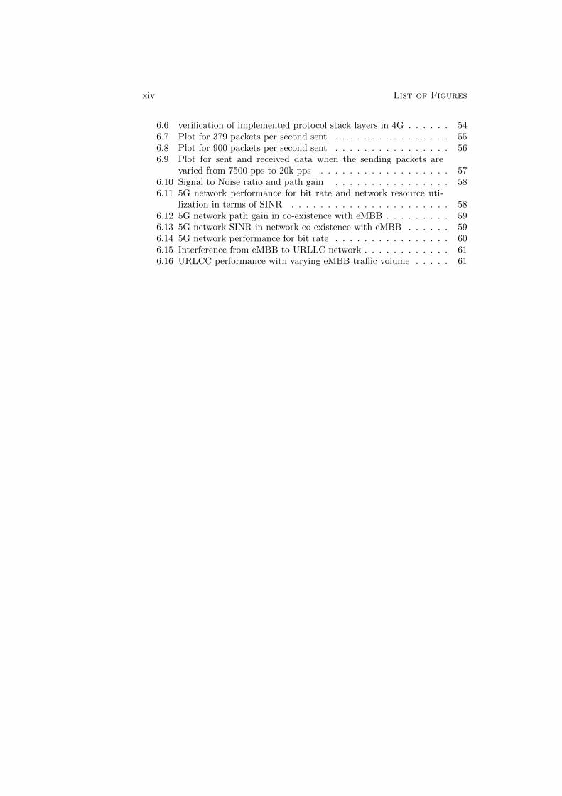
6.6 verification of implemented protocol stack layers in 4G . . . . . . 546.7 Plot for 379 packets per second sent . . . . . . . . . . . . . . . . 556.8 Plot for 900 packets per second sent . . . . . . . . . . . . . . . . 566.9 Plot for sent and received data when the sending packets are
varied from 7500 pps to 20k pps . . . . . . . . . . . . . . . . . . 576.10 Signal to Noise ratio and path gain . . . . . . . . . . . . . . . . 586.11 5G network performance for bit rate and network resource uti-
lization in terms of SINR . . . . . . . . . . . . . . . . . . . . . . 586.12 5G network path gain in co-existence with eMBB . . . . . . . . . 596.13 5G network SINR in network co-existence with eMBB . . . . . . 596.14 5G network performance for bit rate . . . . . . . . . . . . . . . . 606.15 Interference from eMBB to URLLC network . . . . . . . . . . . . 616.16 URLCC performance with varying eMBB traffic volume . . . . . 61
List of Figures xv
List of Acronyms
• 3GPP Third Generation Partnership Project
• ACSI Abstract Communication Service Interface
• AIS Air Insulation Substation
• AMPS Advanced Mobile Phone System
• API Application Programming Interface
• BPSK Binary Phase Shift Keying
• BSS Basic Service Set
• CCK Complementary Code Keying
• CDC Common Data Classes
• CDF Cumulative Distribution Frequency
• CDMA Code Division Multiple Access
• CSMA Carrier Sense Multiple Access
• CT Current Transformer
• DER Distributed Energy Resource
• DSSS Direct Sequence Spread Spectrum
• E-UTRAN Evolved - Universal Terrestrial Access Network
• EDGE Enhanced Data-rate for GSM Evolution
• EMI Electromagnetic Interference
• EPC Evolved Packet Core
• ESS Extended Service Set
• ETSI European Telecommunication Standardization Institute
• EVDO Evolution-Data Optimized
• FDD Frequency Division Duplexing
• FHSS Frequency Hopped Spread Spectrum
• GIS Gas Insulated Switch
• GOOSE Generic Object Oriented Substation Event
• GPRS General Packet Radio Services
• GSM Global System for Mobile communication
• GSSE Generic Substation State Event
xvi List of Figures
• GTP GPS Tunneling Protocol
• GW Gateway
• Gbps Gigabits per second
• HSDPA High Speed Downlink Packet Access
• HSR High Seamless Reliability
• HSUPA High Speed Uplink Packet Access
• IEC International Electro-technical Commission
• IED Intelligent Electronic Devices
• IEEE Institute of Electrical and Electronics Engineers
• IF Interface
• IMT International Mobile Telecommunication
• IP Internet Protocol
• ISO International Standard Organization
• ITU International Telecommunications Union
• IoT Internet of Things
• LAN Local Area Network
• LTE Long Term Evolution
• MAC Medium Access Control
• MAC Media Access Control
• MBB Massive Broadband
• MMS Manufacturing Message Specification
• MTC Machine Type Communication
• Mbps Megabits per second
• NMT Nordic Mobile Telephone
• OFDMA Orthogonal Frequency Division Multiple Access
• OSI Open Systems Interconnection
• PDCP Packet Data Convergence Protocol
• PDCP Packet Data Convergence Protocol
• PDN Packet Data Network
• PLC Programmable Line Communications
List of Figures xvii
• PRP Parallel Redundancy Protocol
• QPSK Quadrature Phase Shift Keying
• QoS Quality of Service
• RAT Radio Access Technology
• RLC Radio Link Control
• RLC Radio Link Control
• RRC Radio Resource Control
• SC-FDMA Single Carrier Frequency Division Multiple Access
• SCADA Supervisory Control and Data Acquisition
• SCSM Specific communication Service mapping
• SDN Software Defined network
• SINR Signal to Interference Noise Ratio
• SOFDMA Scalable Orthogonal Frequency Division Multiple Access
• SON Self Operating Network
• SV Sampled Value
• TDD Time Division Duplexing
• TDMA Time Division Multiple Access
• UDP User Datagram Protocol
• UE User Equipment
• UMTS Universal Mobile Telecommunication Service
• URLLC Ultra Reliable Low Latency Communication
• VT Voltage Transformer
• WIA-PA Wireless Industrial Automation - Process Automation
• WIMAX Worldwide Interoperability for Microwave Access X
• WLAN Wireless Local Area Network
• mm-Wave Millimeter wave
• pps Packets per second

Chapter 1
Introduction
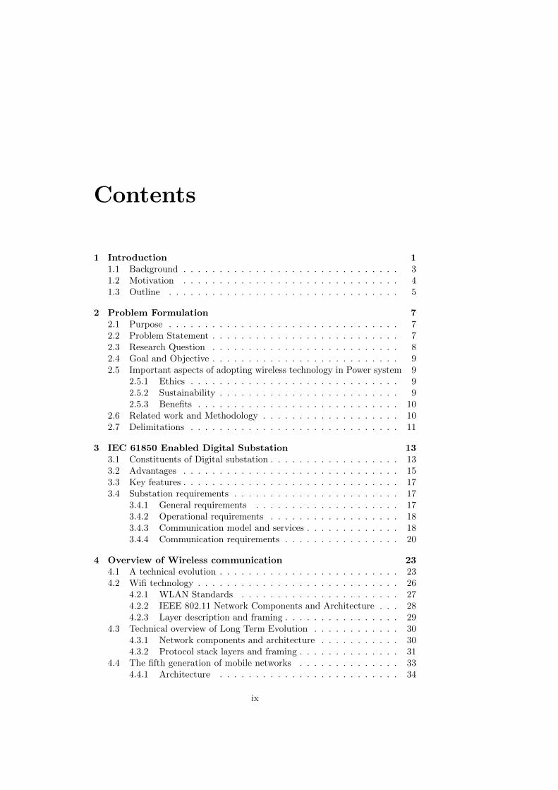
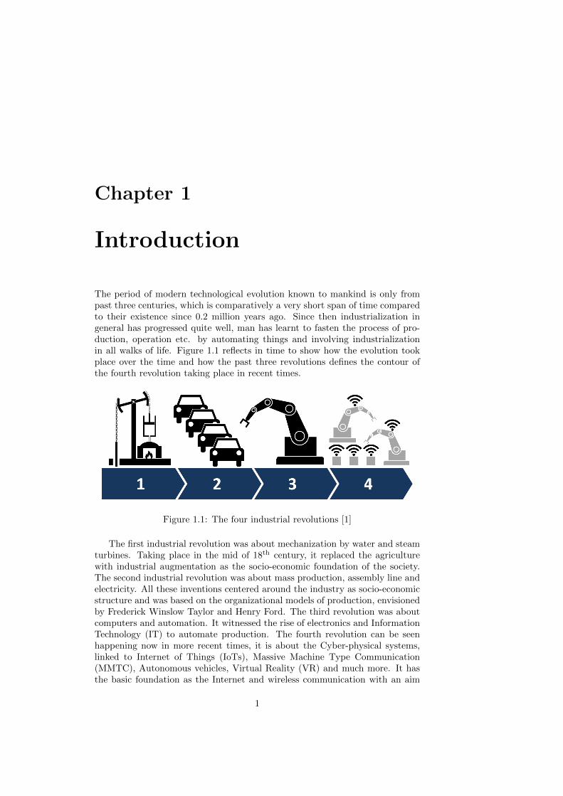
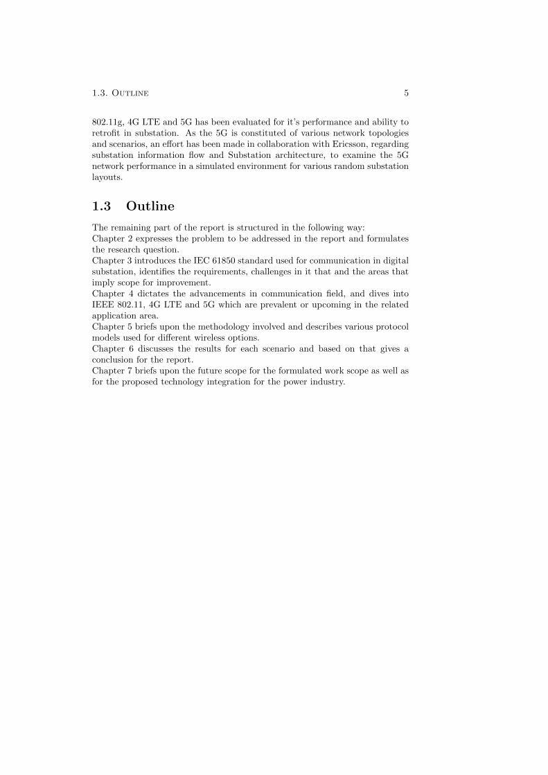
The period of modern technological evolution known to mankind is only frompast three centuries, which is comparatively a very short span of time comparedto their existence since 0.2 million years ago. Since then industrialization ingeneral has progressed quite well, man has learnt to fasten the process of pro-duction, operation etc. by automating things and involving industrializationin all walks of life. Figure 1.1 reflects in time to show how the evolution tookplace over the time and how the past three revolutions defines the contour ofthe fourth revolution taking place in recent times.
Figure 1.1: The four industrial revolutions [1]
The first industrial revolution was about mechanization by water and steamturbines. Taking place in the mid of 18th century, it replaced the agriculturewith industrial augmentation as the socio-economic foundation of the society.The second industrial revolution was about mass production, assembly line andelectricity. All these inventions centered around the industry as socio-economicstructure and was based on the organizational models of production, envisionedby Frederick Winslow Taylor and Henry Ford. The third revolution was aboutcomputers and automation. It witnessed the rise of electronics and InformationTechnology (IT) to automate production. The fourth revolution can be seenhappening now in more recent times, it is about the Cyber-physical systems,linked to Internet of Things (IoTs), Massive Machine Type Communication(MMTC), Autonomous vehicles, Virtual Reality (VR) and much more. It hasthe basic foundation as the Internet and wireless communication with an aim
1
2 Chapter 1. Introduction
to connect every physical system with the cyber world.
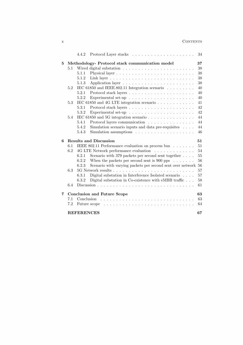
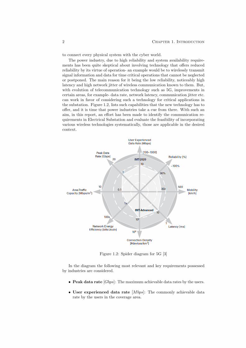
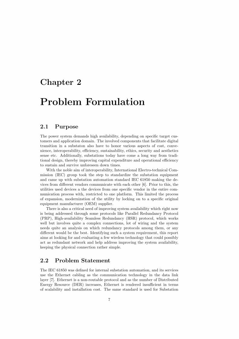
The power industry, due to high reliability and system availability require-ments has been quite skeptical about involving technology that offers reducedreliability by its virtue of operation- an example would be to wirelessly transmitsignal information and data for time critical operations that cannot be neglectedor postponed. The main reason for it being the low reliability, noticeably highlatency and high network jitter of wireless communication known to them. But,with evolution of telecommunication technology such as 5G, improvements incertain areas, for example- data rate, network latency, communication jitter etc.can work in favor of considering such a technology for critical applications inthe substation. Figure 1.2, lists such capabilities that the new technology has tooffer, and it is time that power industries take a cue from there. With such anaim, in this report, an effort has been made to identify the communication re-quirements in Electrical Substation and evaluate the feasibility of incorporatingvarious wireless technologies systematically, those are applicable in the desiredcontext.
Figure 1.2: Spider diagram for 5G [3]
In the diagram the following most relevant and key requirements possessedby industries are considered.
• Peak data rate [Gbps]: The maximum achievable data rates by the users.
• User experienced data rate [Mbps]: The commonly achievable datarate by the users in the coverage area.
1.1. Background 3
• Reliability [%]: The percentage of successful data transmission in a cer-tain amount of time.
• Mobility [km/h]: The maximum achievable vehicular speed at whicha nominal Quality of Service (QoS) can be achieved. (This terminologywould not be that relevant to substation scenario as the substation wouldbe immobile).
• Radio latency [ms]: The one way time required for the data on MediaAccess Control (MAC) layer of the radio interface to travel from sourceto destination.
• Connection density [#devices/km2]: The total number of connecteddevice per area.
• Network energy efficiency [bits/Joule]: Bits per unit of energy con-sumed by the Radio Access Network (RAN) /Communication Module.
• Area traffic capacity [Mbps/m2]: The total traffic throughput servedper unit geographical area.
The security parameter for providing authentication for accessing data, re-garding the privacy of the industries and consumers for a secure network isthough not mentioned in the above diagram is one of the key concerns and a re-search field in itself. This, however does not fall under the scope of investigationfor the present report.
1.1 Background
An electric substation is present in various stages of electricity generation, trans-mission and distribution system. Accordingly, it can be classified such as Gener-ation switch-yard substation, Transmission Substation, Distribution Substationand Customer Substation etc. Also, depending on the level of voltage handledby the substation, it can be classified as High Voltage (HV), Medium Voltage(MV) or Low Voltage (LV) substation. Whatever the category and type of sub-station is, the basic purpose of the substation is to change the voltage level ofthe energy system, it transforms the voltage, drives the power flow, isolates andreroutes the power path as needed and deals with power outages and recovery.
The main constituent of a substation is a transformer, with other importantsub - constituents like switch-gears, circuit breakers and relays. The number oftransformers in a substation can vary from one to many, depending on the sizeand network it caters to, the amount of power/voltage to transform, architec-ture of the transmission/distribution system etc. Time has seen the evolution insubstations. The circuit breakers in the traditional substations would be bulkyand complicated, but the introduction of Gas Insulated Switch-gears (GIS),simplified the procedure a lot and helped reduce the footprint of conventionalAir Insulated Substation (AIS) by 90%. The reliability of small relays and thecriticality of bulk system only welcomed small changes. But gradually, the mi-croprocessor relays replaced the electro-mechanical relays, and introduced thecomputer based digitalization [4]. With growing electric demands, the elec-tric power system becomes more complex, and therefore efficient and reliable
4 Chapter 1. Introduction
operation is much critically needed. This led to the introduction of advancedcommunication technologies, which would help collect the digital data faster andaccurate than before, allowing the Supervisory Control and Data Acquisition(SCADA) system to monitor more nodes with less wiring. The relays that areinvolved in protecting equipment are capable to monitor their health and helpin their timely replacements, if needed. The technology in substation continuesto increase the capabilities, reliability and reduce the maintenance and capitalcost. Automation being one of the driving technology, a standard for digitalautomation substation system has evolved and termed as IEC 61850. Detailsabout the standard and it’s relevance is presented in Chapter 3.
1.2 Motivation
Generally, power industries are quite cautious about adopting new technologies,and sometimes it takes a catastrophic event to force a change. On August 14,2003, a massive blackout throughout parts of the Northeastern and MidwesternUnited States and the Canadian province of Ontario was widespread. Theprimary cause for the same was found to be a software bug in the alarm system atthe control room of First-Energy Corporation, an Akron, Ohio-based company,causing operators to remain unaware of the need to re-distribute load afteroverloaded transmission lines drooped into foliage. It impacted as many as 50million people and prompted governing agencies to enact measures to improvethe electric infrastructure in an effort to reduce outages and prevent blackoutsof this severity. These mandatory measures have driven utilities to invest ingrid technologies to improve system reliability at a faster rate than before theblackout [4]. The IEC 61850 standardization protocol has been quite favorablefor offering a homogenized communication structure at process, bay and stationlevel and remaining vendor agnostic in recent times. But, the implementationis not as fast paced- the reason being, the infrastructure cost and effort of suchreplacement would be too high, which leaves the industries in the dilemma ofchoosing cost over technology and vice versa.
The introduction of various new communication technologies like the opti-cal communications, Ethernet, Programmable Line Communications (PLC) andnow the fourth industrial revolution, the base being the fast growing communica-tion is a motivation to consider the ways of incorporating and getting benefitedby them. The introduction of digitalized relays pave a way for making it moreadaptive to wireless technology, as it minimizes installation costs, dependencyon physical attacks, malfunction of devices and laying of cables for a brownor green field installations. The expected outcomes from 5G communicationtechnology as shown in Figure 1.2 and the fact that their incorporation wouldminimize installation cost for laying of cables for a green or brown field installa-tion and faster installation, commissioning and troubleshooting time makes it afavorable alternative. The wide adoption of the technology that is used in otherparallel fields such as mobile voice/data communication, urban transportation,smart city infrastructure handling, etc. makes it fiercely competitive, thus en-abling more players to act and operate in the space thereby helping operatorsto choose from more technological options and challenges.
The scope of the report involves evaluating the option of wireless technologyas a communication network in substation. Wireless technologies like IEEE
1.3. Outline 5
802.11g, 4G LTE and 5G has been evaluated for it’s performance and ability toretrofit in substation. As the 5G is constituted of various network topologiesand scenarios, an effort has been made in collaboration with Ericsson, regardingsubstation information flow and Substation architecture, to examine the 5Gnetwork performance in a simulated environment for various random substationlayouts.
1.3 Outline
The remaining part of the report is structured in the following way:Chapter 2 expresses the problem to be addressed in the report and formulatesthe research question.Chapter 3 introduces the IEC 61850 standard used for communication in digitalsubstation, identifies the requirements, challenges in it that and the areas thatimply scope for improvement.Chapter 4 dictates the advancements in communication field, and dives intoIEEE 802.11, 4G LTE and 5G which are prevalent or upcoming in the relatedapplication area.Chapter 5 briefs upon the methodology involved and describes various protocolmodels used for different wireless options.Chapter 6 discusses the results for each scenario and based on that gives aconclusion for the report.Chapter 7 briefs upon the future scope for the formulated work scope as well asfor the proposed technology integration for the power industry.

Chapter 2
Problem Formulation
2.1 Purpose
The power system demands high availability, depending on specific target cus-tomers and application domain. The involved components that facilitate digitaltransition in a substaton also have to honor various aspects of cost, conve-nience, interoperability, efficiency, sustainability, ethics, security and aestheticssense etc. Additionally, substations today have come a long way from tradi-tional design, thereby improving capital expenditure and operational efficiencyto sustain and survive unforeseen down times.
With the noble aim of interoperability, International Electro-technical Com-mission (IEC) group took the step to standardize the substation equipmentand came up with substation automation standard IEC 61850 making the de-vices from different vendors communicate with each other [6]. Prior to this, theutilities used devices a the devices from one specific vendor in the entire com-munication process with, restricted to one platform. This limited the processof expansion, modernization of the utility by locking on to a specific originalequipment manufacturer (OEM) supplier.
There is also a critical need of improving system availability which right nowis being addressed through some protocols like Parallel Redundancy Protocol(PRP), High-availability Seamless Redundancy (HSR) protocol, which workswell but involves quite a complex connections, lot of wiring and the systemneeds quite an analysis on which redundancy protocols among them, or anydifferent would be the best. Identifying such a system requirement, this reportaims at looking for and evaluating a few wireless technology that could possiblyact as redundant network and help address improving the system availability,keeping the physical connection rather simple.
2.2 Problem Statement
The IEC 61850 was defined for internal substation automation, and its servicesuse the Ethernet cabling as the communication technology in the data linklayer [7]. Ethernet is a non-routable protocol and as the number of DistributedEnergy Resource (DER) increases, Ethernet is rendered insufficient in termsof scalability and installation cost. The same standard is used for Substation
7
8 Chapter 2. Problem Formulation
Automation System (SAS) and for the information exchange in smart grids.As the amount of message on the communication network increases with thegrowing number of Intelligent Electronic Devices (IEDs) in one collision domain,the risk of violation of transmission time requirement increases. This requires aneed of optimization of IEC 61850 based communication network.
Also the time when IEC 61850 for process and station bus within substationwas defined, it was meant to be communicated in real time and preferablyon Ethernet links as a suggested standard as there was unavailability of fastwireless communication standards. The growing popular wireless technologiesthese days pave ways for alternate path of substation messages and optimizethe communication network, provided they offer same/similar reliability as thewired solution.
The new update in the documentation IEC 61850-90-5 mentions about theoption of incorporating wireless technology in the standard and routing theprocess bus and station bus critical messages on wireless media with the condi-tion that it meets the concerned communication message latency requirement.Though existence of such substation in practice is not very common yet. There-fore, implementation challenges in exploring these challenges to Ethernet be-comes imperative and hence forms subject matter of this report.
2.3 Research Question
In the complete digital substation, the components (Merging Units, Switches,IEDs, time synchronization sources) at various levels (Process, Bay and Stationlevel) may affect the availability of the system. In order to achieve the higheravailability of the communication network with the aim of achieving faster andreliable performance, this report aims at bringing a transition phase to the sub-station from all wired to complete wireless. For that matter the communicationrequirements would be identified in the report, and an attempt has been madeto evaluate the wireless network performance by calculating the latency andpacket loss of the process bus that connects from the Merging unit at the pro-cess level to the IEDs at the bay level. In the context of the report, severalresearch questions can be posed with the aim to see how wireless technologycomplements the IEC 61850 Ethernet communication network as a redundantsolution in this transition and possibly could be seriously evaluated for a com-plete wireless substation in the far future. Thus the following research questionshas been addressed in the report.
• Given the merits of the WLAN in recent times, are the WLANs based onIEEE 802.11g, suitable for transmitting the process level information?
• 4G LTE is gaining popularity in many of smart grid applications, are theycapable of solving the said problem?
• 5G is one of the emerging topics and promises many capabilities that areten times higher than 4G LTE [3] in terms of latency, speed, reliability,connection density and network capacity. Does it stand a chance to enterthe power industry and participate in real time communication of substa-tion process level data?
2.4. Goal and Objective 9
2.4 Goal and Objective
The goal of this report is to experimentally investigate the performance of IEEE802.11g and 4G LTE release 14 for the transmission of process bus data inthe IEC 61850 environment and also to evaluate 5G network in a simulationenvironment for the same traffic.
The deliverable of the project will be of two different kinds.
1. For the experimental scenario to evaluate the performance of IEEE 802.11gand 4G LTE towards:
• The latency of SV on the Physical layer
• The packet loss
2. For the simulation scenario in 5G environment to quantify:
• Bitrate vs Cumulative Distribution Frequency (CDF)
• Signal to Interference Noise Ratio (SINR) vs CDF.
Based on the results, if the aim of achieving a redundant network is possibleby wireless then it would be quite beneficial for the power industry.
2.5 Important aspects of adopting wireless tech-nology in Power system
Ethics, sustainability and benefits form an important aspect of this primitivestage work. They are discussed in the sub-sections below.
2.5.1 Ethics
The wireless communication always concerns the data privacy and data securityissues. The ethical issues may arise since the power industry would have thedata of energy utilization of the system, but taking the legal standards intoconsiderations they can be solved. This issue can be studied in legal aspectsand right now is out of scope of the report.
2.5.2 Sustainability
The sustainable electricity infrastructure requires a flexible and smarter powernetwork that allows a greater scope for demand participation, storage facilitiesand many other flexible options [9]. The optimized communication networkand high available power system aim for the same. According to EuropeanRegulators Group for Electricity and Gas, a fully-functioning smart grid wouldexploit communication networks to ”cost-efficiently integrate the actions of allusers connected to it - producers, consumers and prosumers - to ensure aneconomically efficient, sustainable power system with low losses and high levelsof quality and security of supply and safety” [9].
10 Chapter 2. Problem Formulation
2.5.3 Benefits
It not only simplifies the design and reduce the cable and area of substation butalso capable of promoting the development of digital substation and providestrong support to the construction of smart grid. Wireless digital technology isa future technology carrying an enormous amount of benefits for the SubstationAutomation System (SAS) major benefits being.
• Protection and measurements systems in the electrical substations wouldhave high availability. [8]
• Communication network optimization for fast monitoring and control ap-plication.
• Technology being compliant with IEC 61850 standard would be inter-operable with the standard devices.
2.6 Related work and Methodology
According to [10], the use of redundant systems has been considered in severalsituations. To optimize the communication network and/or to build a redundantnetwork, the approach would start from identifying the type of information thatflow in the network and their communication requirements. [7] specifies fivedifferent kind of information flow and the types they are classified in as per thelatency requirements.
[11] identifies the Manufacturing Message Specification (MMS) for the smartmetering communications and to answer the research questions identified, itused the literature study and waterfall research method, and the evaluation ofIEC 61850 MMS smart metering traffic over LTE network was performed inNS3 LENA simulation environment. [12] investigates the performance of LongTerm Evolution (LTE) communications technology with QoS enabled features,for wide area measurement acquisition and control, using IEC 61850 standardcommunication services. The methodology involved real time testing in lab ofintegrating an LTE infrastructure with IED and SCADA system. The real powersystem was emulated and the information sent over the network was MMS pro-tocol messages. The paper concluded that LTE could meet the communicationrequirements of MMS messages that belonged to performance class P4, P5 andP6 described in IEC 61850 standards.
[13] was involved in enabling a for control system applications in a smart gridcontext, not specifically involved in within substation communication scenariobut with inter-substation communication for smart Grid. The methodologyinvolved four stages: mapping over LTE protocol stack layers, QoS provisioning,analytical modeling and scheduler design. It was tried on a simulation platform.The research focused on control system applications in smart grid and thus onlythe GOOSE and MMS were involved in being transmitted over the LTE network.
Among the five different kind of information that flow in IEC 61850 basedsubstations (SV, Generic Object Oriented Substation Event (GOOSE), GenericSubstation Event (GSSE), Time sync and Client-Server MMS), the SV, GOOSEand GSSE are the time critical ones. Therefore efforts made to transmit thesesignals over wireless medium are rather scanty in literature. Among the fewthose attempted to transmit the time critical signals, [13] tried sending the
2.7. Delimitations 11
GOOSE message over LTE, but only in simulated environment. There has beenan effort also to send the SV data over the wireless media and vision the processlevel as wireless which is discussed in following paragraphs.
[14] implemented WLAN peer-to-peer feeder protection in smart grid substa-tion system. IEEE802.11 having enabled cost-effective remote control systemswith a capability of monitoring, control and protection in the real-time oper-ating conditions of substations is used in OPNET simulation scenario. In thissimulation scenario the transmission latency and throughput of SV and GOOSEare evaluated. [15] presents a wireless data acquisition system. The work of de-veloping the acquisition system is laboratory based and is experimental. For theWireless Industrial Automation - Process Automation (WIA-PA), the wirelessadapter and the intelligent gateway was designed. The system here had beenapplied in pilot substation, which verifies its excellent communication perfor-mance, and there is a good prospect for the substation application. However,not much about the performance of data over the network is discussed andaccording to the authors there are still many issues, including integrated op-timization and communication stability that could be a future scope for thatparticular project.
As per the literature survey done, SV is not yet sent on a 4G or 5G networkand as part of the present report ”Feasibility study for substation communica-tion using parallel redundant wireless technology” is carried out. The attemptmade here is rather systematic to send the SV traffic over three different wire-less networks, e.g. IEEE 802.11g, 4G LTE release 14 routers and 5G. Themethodology for scenarios of implementation would be be based on laboratoryexperimental methods in case of IEEE 802.11g and 4G. The experiments woulduse the infrastructure available from a Merging Unit (MU) system of a digitalsubstation framework. The SV data is then transmitted over optical cable to aremote location where the wireless techniques of different kind are tested. Sucha setup (explained in enough detail in 5 chapter), helps facilitation and vali-dation of the SV traffic flow from the switch yard- transformer location to thecontrol room, where the IEDs are physically located. The approach towards theexperimental setup closely mimics the on communication model of 7-layer stackof protocols and appropriate modifications to incorporate the wireless transmis-sion in the network layer. The 5G scenario is implemented for the same SVtraffic, in a simulation environment, with a typical substation dimensions andlayout by appropriately accounting for the physical barriers and other networktraffic that could be potentially present.These are discussed in enough detail inthe subsequent chapters.
2.7 Delimitations
In the electric system with high voltage around, there are high probability ofElectromagnetic interferences (EMI) present, but the experiment was carriedout by is in the two different labs which are physically apart the EMI does notdisturb the wireless communication here and is not taken into consideration.The background traffic and noise disturbances for wireless network is not takeninto account and is assumed that the network only carries the substation SVdata, as the initial aim is to see if the WiFi/4G networks meet the latency andthroughput without disturbance and if the result is positive then the scenario
12 Chapter 2. Problem Formulation
in case of background disturbances can be considered as next step and if notthen it could be concluded accordingly that it might not meet communicationrequirements.
Chapter 3
IEC 61850 Enabled DigitalSubstation
Communication system plays a vital role in real-time operation of power system.In earlier times when the traditional substations had just come into picture, itwas not automated to communicate information but the telephones were usedby the operators to communicate with the control centers to perform switchingoperations at the control center. This switching technique was used back in1930s and were able to provide status and control of only few points. As digitalcommunication became a viable option in 1960’s, Data Acquisition System wereinstalled to automate data measurement from the substations.
The objective of Substation Automation standardization is to develop a com-munication standard that meets all functional and performance-based require-ments and meanwhile, supporting future technological developments too. Thepossibility to build a successful and efficient SAS largely depends on technolog-ical developments that builds large integrated circuits as IEDs and can includevarious protection and control in it. The reliability depends on communicationsystems involved. The major features, structure and functionality of IEC 61850is described in this chapter.
3.1 Constituents of Digital substation
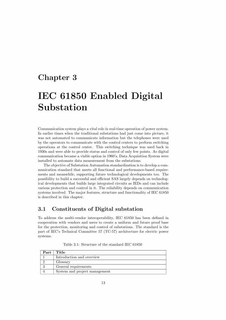
To address the multi-vendor interoperability, IEC 61850 has been defined incooperation with vendors and users to create a uniform and future proof basefor the protection, monitoring and control of substations. The standard is thepart of IEC’s Technical Committee 57 (TC-57) architecture for electric powersystems.
Table 3.1: Structure of the standard IEC 61850
Part Title
1 Introduction and overview
2 Glossary
3 General requirements
4 System and project management
13
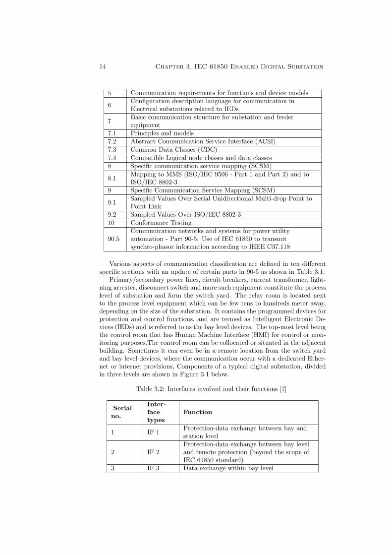
14 Chapter 3. IEC 61850 Enabled Digital Substation
5 Communication requirements for functions and device models
6Configuration description language for communication inElectrical substations related to IEDs
7Basic communication structure for substation and feederequipment
7.1 Principles and models
7.2 Abstract Communication Service Interface (ACSI)
7.3 Common Data Classes (CDC)
7.4 Compatible Logical node classes and data classes
8 Specific communication service mapping (SCSM)
8.1Mapping to MMS (ISO/IEC 9506 - Part 1 and Part 2) and toISO/IEC 8802-3
9 Specific Communication Service Mapping (SCSM)
9.1Sampled Values Over Serial Unidirectional Multi-drop Point toPoint Link
9.2 Sampled Values Over ISO/IEC 8802-3
10 Conformance Testing
90.5Communication networks and systems for power utilityautomation - Part 90-5: Use of IEC 61850 to transmitsynchro-phasor information according to IEEE C37.118
Various aspects of communication classification are defined in ten differentspecific sections with an update of certain parts in 90-5 as shown in Table 3.1.
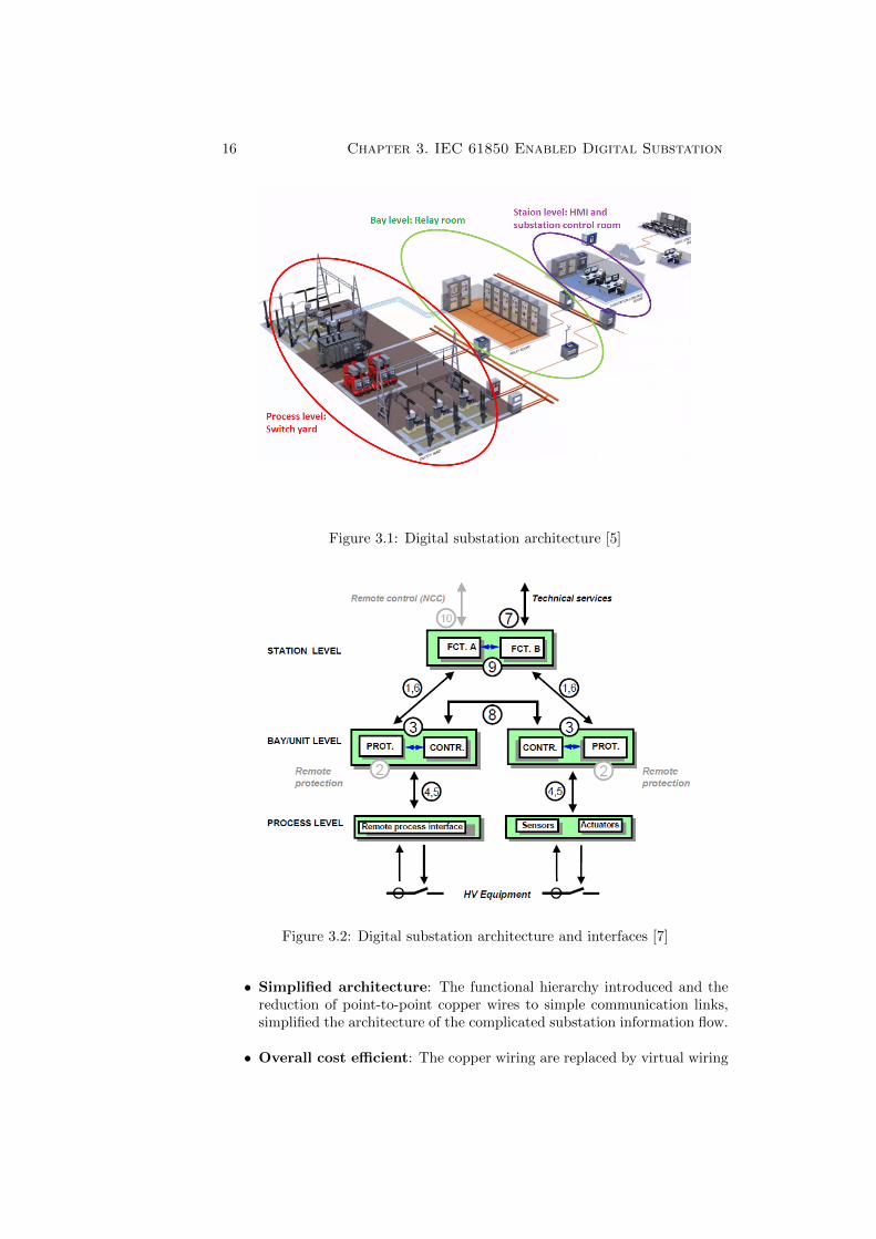
Primary/secondary power lines, circuit breakers, current transformer, light-ning arrester, disconnect switch and more such equipment constitute the processlevel of substation and form the switch yard. The relay room is located nextto the process level equipment which can be few tens to hundreds meter away,depending on the size of the substation. It contains the programmed devices forprotection and control functions, and are termed as Intelligent Electronic De-vices (IEDs) and is referred to as the bay level devices. The top-most level beingthe control room that has Human Machine Interface (HMI) for control or mon-itoring purposes.The control room can be collocated or situated in the adjacentbuilding. Sometimes it can even be in a remote location from the switch yardand bay level devices, where the communication occur with a dedicated Ether-net or internet provisions, Components of a typical digital substation, dividedin three levels are shown in Figure 3.1 below.
Table 3.2: Interfaces involved and their functions [7]
Serialno.
Inter-facetypes
Function
1 IF 1Protection-data exchange between bay andstation level
2 IF 2Protection-data exchange between bay leveland remote protection (beyond the scope ofIEC 61850 standard)
3 IF 3 Data exchange within bay level
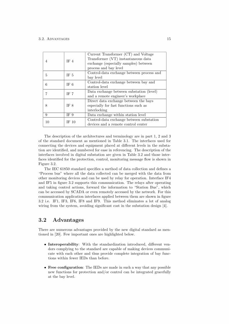
3.2. Advantages 15
4 IF 4
Current Transformer (CT) and VoltageTransformer (VT) instantaneous dataexchange (especially samples) betweenprocess and bay level
5 IF 5Control-data exchange between process andbay level
6 IF 6Control-data exchange between bay andstation level
7 IF 7Data exchange between substation (level)and a remote engineer’s workplace
8 IF 8Direct data exchange between the baysespecially for fast functions such asinterlocking
9 IF 9 Data exchange within station level
10 IF 10Control-data exchange between substationdevices and a remote control center
The description of the architectures and terminology are in part 1, 2 and 3of the standard document as mentioned in Table 3.1. The interfaces used forconnecting the devices and equipment placed at different levels in the substa-tion are identified, and numbered for ease in referencing. The description of theinterfaces involved in digital substation are given in Table 3.2 and those inter-faces identified for the protection, control, monitoring message flow is shown inFigure 3.2.
The IEC 61850 standard specifies a method of data collection and defines a“Process bus” where all the data collected can be merged with the data fromother monitoring devices and can be used by relay for operation. Interface IF4and IF5 in figure 3.2 supports this communication. The relays after operatingand taking control actions, forward the information to “Station Bus”, whichcan be accessed by SCADA or even remotely accessed by the network. For thiscommunication application interfaces applied between them are shown in figure3.2 i.e. IF1, IF3, IF6, IF8 and IF9. This method eliminates a lot of analogwiring from the system, avoiding significant cost in the substation design [4].
3.2 Advantages
There are numerous advantages provided by the new digital standard as men-tioned in [20]. Few important ones are highlighted below.
• Interoperability: With the standardization introduced, different ven-dors complying to the standard are capable of making devices communi-cate with each other and thus provide complete integration of bay func-tions within fewer IEDs than before.
• Free configuration: The IEDs are made in such a way that any possiblenew functions for protection and/or control can be integrated gracefullyat the bay level.
16 Chapter 3. IEC 61850 Enabled Digital Substation
Figure 3.1: Digital substation architecture [5]
Figure 3.2: Digital substation architecture and interfaces [7]
• Simplified architecture: The functional hierarchy introduced and thereduction of point-to-point copper wires to simple communication links,simplified the architecture of the complicated substation information flow.
• Overall cost efficient: The copper wiring are replaced by virtual wiring
3.3. Key features 17
within the IEDs as functions and optical wiring between substation equip-ment that saves a lot of time and cost in substation automation.
3.3 Key features
IEC 61850 provides an object oriented approach, its key features can be sum-marized as below [16].
• Virtualized models: The definition of data, services, and behavior ofdevices to be defined in addition to the protocols that are used to definedata transmission over the network, are enabled by the virtualized modelsof logical devices, logical nodes, ACSI and CDCs.
• New communication services: Multiple information exchange meth-ods are introduced by new communication devices, which cover reportingand logging of events, control switches and functions, poll data model in-formation, real time peer-to-peer communication, sampled value exchangeand file transfer for disturbance recording.
• Independence from communication technologies: The data modeland communication services are decoupled from specific communicationtechnologies. This technology independence guarantees long term stabilityof data model and opens up the possibility of switching between differentcommunication technologies.
• The Common formal description code: The standard IEC 61850possess the Substation Configuration Language (SCL), which allows thestandardized representation of all data model and covers all the com-munication aspects providing an ideal electronic interchange format forconfiguration data.
3.4 Substation requirements
In order to implement the digital substation there are certain requirements thatneeds to be fulfilled and they are mentioned in the subsections below:
3.4.1 General requirements
A substation should remain operable and in no condition, the failure of onedevice should stop the functionality of rest of the substation. If an SAS is re-dundant in connection, then it should be ensured that there should not be anymode of failure that would make both the connection disabled. The manufac-turer of the equipment should provide Mean Time to Failure (MTTF) clearly.To avoid any failure to stop critical functions it should be ensured that: protec-tive functions operate autonomously, SAS may be used to execute control logicactions that are not time-critical, and Human Machine Interface (HMI) shouldoperate independent of tele control interface to control center [6]. Automaticrecovery shall be considered and instead of sudden failure, there should be grad-ual graceful degradation. Maintainability, security and data integrity shall betaken into consideration. The communication network in substation should be
18 Chapter 3. IEC 61850 Enabled Digital Substation
capable to communicate up to 2 km. The equipment and IEDs used in substa-tions shall be able to operate in temperature, pressure, humidity requirementsas mentioned in document IEC 60870-2. The communication equipment is en-tirely subjected to electromagnetic fields. IEC 61000-4-16, IEC 61000-4-8 andIEC 61000-4-10 gives a good reference for the same [6].
3.4.2 Operational requirements
The operational requirement in a substation is characterized by following keypoints.
• Interoperability: The interoperability refers to ability of devices to com-municate with each other even if they are from different manufactures. Fortwo devices to be able, to inter-operate they should, have same syntax i.e.they should be using same protocol to connect to a common bus, thedevices should understand the semantics from other devices and the de-vices shall be able to contribute in performing some function that may bedistributed.
• Redundancy: Though the existing communication networks are majorlyhardwired, they cannot completely rely upon taking into considerationthe glitches in network due to breakage of communication links. So, theback-up option of sending messages are dealt by introducing redundancyby means of Parallel Redundancy Protocol (PRP) or Highly SeamlessReliable Ring (HSR) Protocol, as adopted by different industries.
• Response behavior: The reaction of the nodes should not be delayedand should meet the overall requirements of the transfer time. The be-havior of function in any degraded case must be specified.
• Static design: The function in the equipment design should describe theinformation exchange. the devices are free to be allocated the functionsor parts of it, and together they are required perform a specific function.
• Dynamic requirements: The information of the transfer data, shallbe defined with all it’s attributes and the transfer time of it shall beguaranteed.
3.4.3 Communication model and services
The ASCI models of IEC 61850 define a set of services that enable common be-havior of power system automation from network behavior perspective and arecritical in achieving the interoperability. These models operate over a real setof protocols that are practical to implement and operate in computing environ-ments that can be easily found in the industry [19]. The application associationmodel in the standard, consists of provisions on how the communication betweenthe various model are achieved. It defines the services provided for managingassociations between client server (example MMS) and for multi-cast messaging(example SV and GOOSE). They provide mechanism for access control to adevice. There are two kind of application associations: Two Party ApplicationAssociation (TPAA) and Multi-cast Application Association (MCAA). In par-ticular TPAA is bi-directional flow of information and is connection oriented,
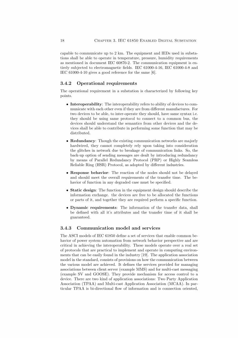
3.4. Substation requirements 19
the information exchanged is performed by an end-to-end flow control as shownin figure 3.3.
Figure 3.3: Two-Party Application Association [19]
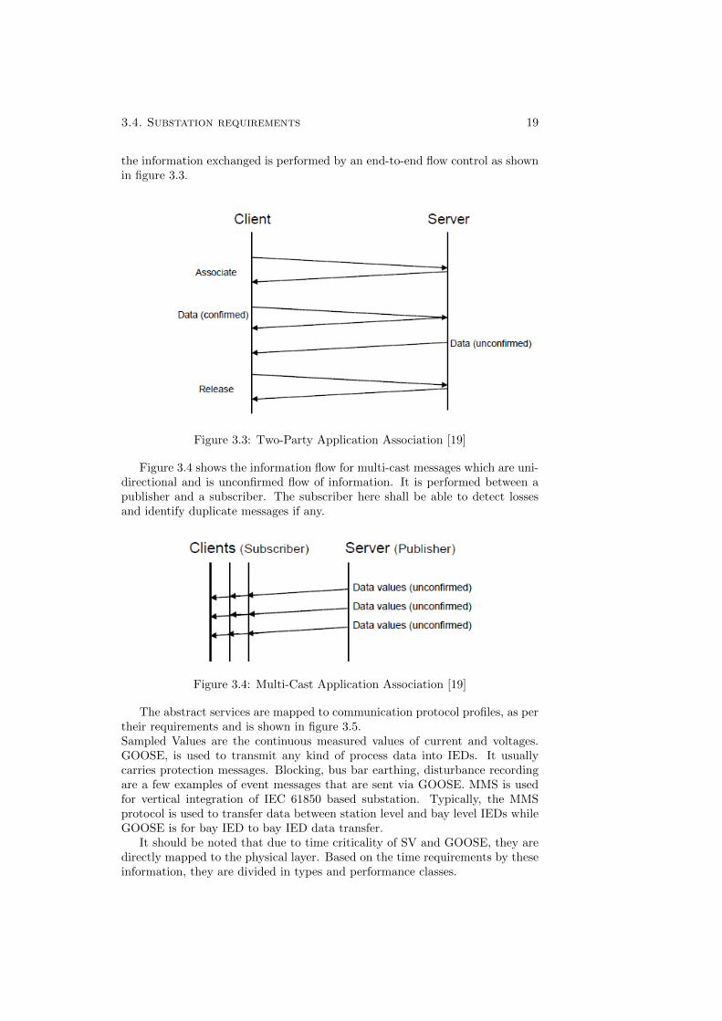
Figure 3.4 shows the information flow for multi-cast messages which are uni-directional and is unconfirmed flow of information. It is performed between apublisher and a subscriber. The subscriber here shall be able to detect lossesand identify duplicate messages if any.
Figure 3.4: Multi-Cast Application Association [19]
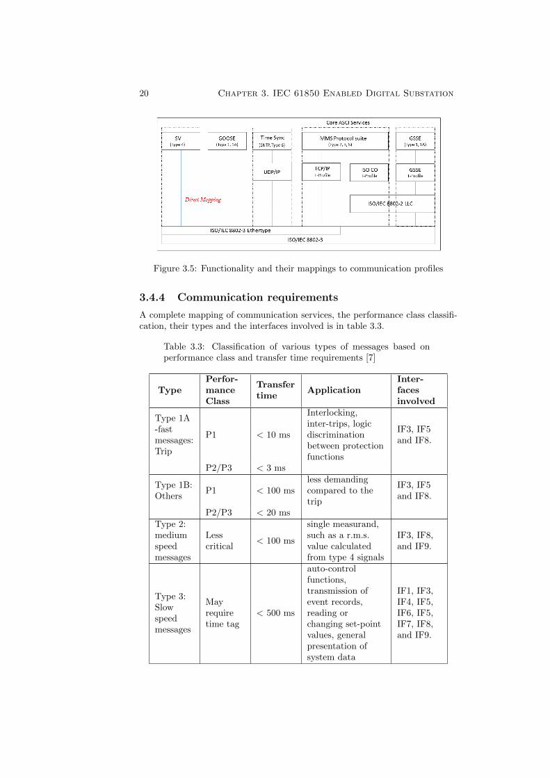
The abstract services are mapped to communication protocol profiles, as pertheir requirements and is shown in figure 3.5.Sampled Values are the continuous measured values of current and voltages.GOOSE, is used to transmit any kind of process data into IEDs. It usuallycarries protection messages. Blocking, bus bar earthing, disturbance recordingare a few examples of event messages that are sent via GOOSE. MMS is usedfor vertical integration of IEC 61850 based substation. Typically, the MMSprotocol is used to transfer data between station level and bay level IEDs whileGOOSE is for bay IED to bay IED data transfer.
It should be noted that due to time criticality of SV and GOOSE, they aredirectly mapped to the physical layer. Based on the time requirements by theseinformation, they are divided in types and performance classes.
20 Chapter 3. IEC 61850 Enabled Digital Substation
Figure 3.5: Functionality and their mappings to communication profiles
3.4.4 Communication requirements
A complete mapping of communication services, the performance class classifi-cation, their types and the interfaces involved is in table 3.3.
Table 3.3: Classification of various types of messages based onperformance class and transfer time requirements [7]
TypePerfor-manceClass
Transfertime
ApplicationInter-facesinvolved
Type 1A-fastmessages:Trip
P1 < 10 ms
Interlocking,inter-trips, logicdiscriminationbetween protectionfunctions
IF3, IF5and IF8.
P2/P3 < 3 ms
Type 1B:Others
P1 < 100 msless demandingcompared to thetrip
IF3, IF5and IF8.
P2/P3 < 20 ms
Type 2:mediumspeedmessages
Lesscritical
< 100 ms
single measurand,such as a r.m.s.value calculatedfrom type 4 signals
IF3, IF8,and IF9.
Type 3:Slowspeedmessages
Mayrequiretime tag
< 500 ms
auto-controlfunctions,transmission ofevent records,reading orchanging set-pointvalues, generalpresentation ofsystem data
IF1, IF3,IF4, IF5,IF6, IF5,IF7, IF8,and IF9.
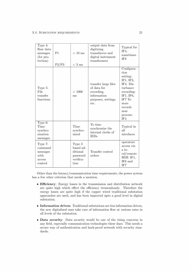
3.4. Substation requirements 21
Type 4:Raw datamessages(for pro-tection)
P1 < 10 ms
output data fromdigitizingtransducers anddigital instrumenttransformers
Typical forIF4,sometimesIF8
P2/P3 < 3 ms
Type 5:Filetransferfunctions
< 1000ms
transfer large filesof data forrecording,informationpurposes, settings,etc.
Configura-tionsetting:IF1, IF3,IF4. Dis-turbancerecording:IF1, IF6,IF7 Tostorerecordsnearprocess:IF4
Type 6:Timesynchro-nizationmessages
Timesynchro-nized
To timesynchronize theinternal clocks ofIEDs
Typical inallinterfaces
Type 7:commandmessageswithaccesscontrol
Type 3based ad-ditionalpasswordverifica-tion
Transfer controlorders
operatorsaccess viaa lo-cal/remoteHMI: IF1,IF6 andIF7
Other than the latency/communication time requirements, the power systemhas a few other criterion that needs a mention.
• Efficiency: Energy losses in the transmission and distribution networkare quite high which effect the efficiency tremendously. Therefore theenergy losses are quite high if the copper wired traditional substationapproaches are used, and has been improved upto a good level in digitalsubstation.
• Information driven: Traditional substations are less information driven,the new digitalized ones take care of information flow at various rates inall levels of the substation.
• Data security: Data security would be one of the rising concerns inany field, especially communication technologies these days. This needs asecure way of authentication and hack-proof network with security stan-dards.
22 Chapter 3. IEC 61850 Enabled Digital Substation
• Availability and reliability: The critical protection functions for thehigh availability of the power system requires high reliability and avail-ability of communication network. This is achieved by introducing redun-dancy in network.
In this thesis, the focus is on SV messages, which is Type 4 raw data measuredvalues, based on MCAA, flows in interface IF4 and belongs to performance classP3 based on the time requirement of < 3 ms.
Chapter 4
Overview of Wirelesscommunication
The main standardization bodies for wireless communication in Europe havebeen: (International Telecommunications Union (ITU), European Telecommu-nication Standardization Institute (ETSI) and Third Generation Partnershipproject (3GPP/3GPP2). The IMT-2000 is a set of standards created for mo-bile communications to meet the specifications of ITU, created after the year2000. The 3GPP is the partnership of various standardization organizationsfrom multiple countries and is the standardization group within IMT-2000 forthe evolution of Global System for Mobile (GSM) Communication, and 3GPP2is for the evolution of CDMA2000.
4.1 A technical evolution
The evolution of wireless technology has come a long way from first generationof analog communications to a heterogeneous fifth generation network. As thewireless technology is in the process of evolution they grow in terms of increasingdata rate, mobility, coverage and spectral efficiency. Figure 4.1 shows how earliertechnologies like 1G and 2G were circuit switched, 2.5G and 3G were both circuitand packet switched and 3.5G onwards all are packet switched. These changesare in the licensed spectrum. While the wifi, bluetooth and WiMax are inunlicensed spectrum.
The First generation 1G, introduced in the market in 1980’s had its ma-jor subscribers as Advanced Mobile Phone System (AMPS), Nordic MobileTelephone (NMT) and Telephone Access Communication System (TACS). Theachievable data rate was 2.4 kbps. The voice calls here were stored and playedin radio towers, which were quite unsecure in terms of data privacy as it wasmore vulnerable to third party evesdropping.
With the introduction of 2nd generation of mobile telecommunication theGlobal System for Mobile(GSM) communication, the digital technology wasused in it and it was chiefly meant for voice communications with short messageservice (SMS) and emails. The eminent technologies involved in this generationwas GSM, CDMA and IS-95. 2G was followed by a new release which used the2G framework merged with the General Packet Radio Services (GPRS), and
23
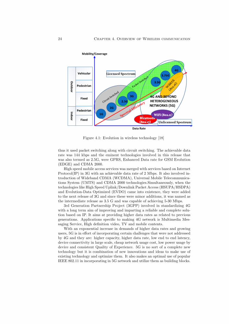
24 Chapter 4. Overview of Wireless communication
Figure 4.1: Evolution in wireless technology [18]
thus it used packet switching along with circuit switching. The achievable datarate was 144 kbps and the eminent technologies involved in this release thatwas also termed as 2.5G, were GPRS, Enhanced Data rate for GSM Evolution(EDGE) and CDMA 2000.
High speed mobile access services was merged with services based on InternetProtocol(IP) in 3G with an achievable data rate of 2 Mbps. It also involved in-troduction of Wideband CDMA (WCDMA), Universal Mobile Telecommunica-tions System (UMTS) and CDMA 2000 technologies.Simultaneously, when thetechnologies like High Speed Uplink/Downlink Packet Access (HSUPA/HSDPA)and Evolution-Data Optimized (EVDO) came into existence, they were addedto the next release of 3G and since these were minor additions, it was named asthe intermediate release as 3.5 G and was capable of achieving 5-30 Mbps.
3rd Generation Partnership Project (3GPP) involved in standardizing 4Gwith a long term aim of improving and imparting a reliable and complete solu-tion based on IP. It aims at providing higher data rates as related to previousgenerations. Applications specific to making 4G network is Multimedia Mes-saging Service, High definition video, TV and mobile contents.
With an exponential increase in demands of higher data rates and growingusers, 5G is in effort of incorporating certain challenges that were not addressedby 4G and they are: higher capacity, higher data rate, low end to end latency,device connectivity in large scale, cheap network usage cost, low power usage bydevice and consistent Quality of Experience. 5G is no sort of a complete newtechnology but it is combination of new innovations and ideas to make use ofexisting technology and optimize them. It also makes an optimal use of popularIEEE 802.11 in incorporating in 5G network and utilize them as building blocks.
4.1. A technical evolution 25
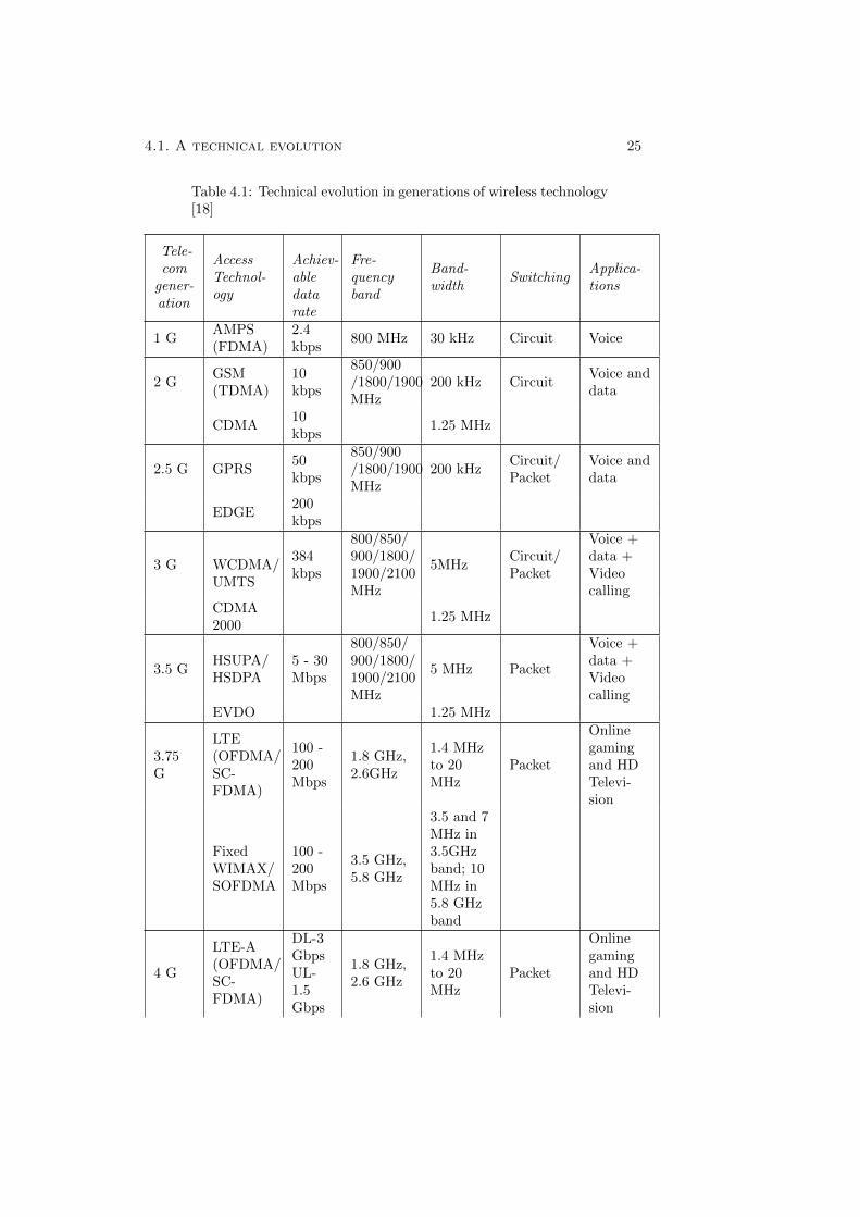
Table 4.1: Technical evolution in generations of wireless technology[18]
Tele-com
gener-ation
AccessTechnol-ogy
Achiev-abledatarate
Fre-quencyband
Band-width
SwitchingApplica-tions
1 GAMPS(FDMA)
2.4kbps
800 MHz 30 kHz Circuit Voice
2 GGSM(TDMA)
10kbps
850/900/1800/1900MHz
200 kHz CircuitVoice anddata
CDMA10kbps
1.25 MHz
2.5 G GPRS50kbps
850/900/1800/1900MHz
200 kHzCircuit/Packet
Voice anddata
EDGE200kbps
3 G WCDMA/UMTS
384kbps
800/850/900/1800/1900/2100MHz
5MHzCircuit/Packet
Voice +data +Videocalling
CDMA2000
1.25 MHz
3.5 GHSUPA/HSDPA
5 - 30Mbps
800/850/900/1800/1900/2100MHz
5 MHz Packet
Voice +data +Videocalling
EVDO 1.25 MHz
3.75G
LTE(OFDMA/SC-FDMA)
100 -200Mbps
1.8 GHz,2.6GHz
1.4 MHzto 20MHz
Packet
Onlinegamingand HDTelevi-sion
FixedWIMAX/SOFDMA
100 -200Mbps
3.5 GHz,5.8 GHz
3.5 and 7MHz in3.5GHzband; 10MHz in5.8 GHzband
4 G
LTE-A(OFDMA/SC-FDMA)
DL-3GbpsUL-1.5Gbps
1.8 GHz,2.6 GHz
1.4 MHzto 20MHz
Packet
Onlinegamingand HDTelevi-sion
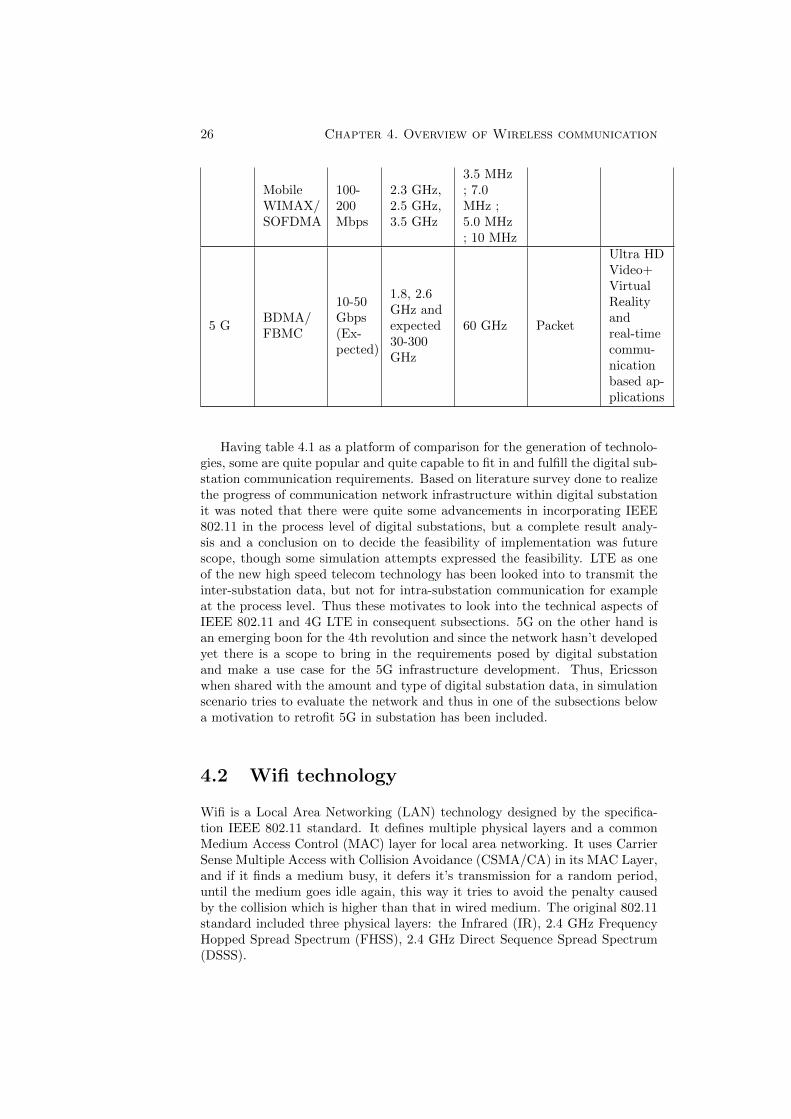
26 Chapter 4. Overview of Wireless communication
MobileWIMAX/SOFDMA
100-200Mbps
2.3 GHz,2.5 GHz,3.5 GHz
3.5 MHz; 7.0MHz ;5.0 MHz; 10 MHz
5 GBDMA/FBMC
10-50Gbps(Ex-pected)
1.8, 2.6GHz andexpected30-300GHz
60 GHz Packet
Ultra HDVideo+VirtualRealityandreal-timecommu-nicationbased ap-plications
Having table 4.1 as a platform of comparison for the generation of technolo-gies, some are quite popular and quite capable to fit in and fulfill the digital sub-station communication requirements. Based on literature survey done to realizethe progress of communication network infrastructure within digital substationit was noted that there were quite some advancements in incorporating IEEE802.11 in the process level of digital substations, but a complete result analy-sis and a conclusion on to decide the feasibility of implementation was futurescope, though some simulation attempts expressed the feasibility. LTE as oneof the new high speed telecom technology has been looked into to transmit theinter-substation data, but not for intra-substation communication for exampleat the process level. Thus these motivates to look into the technical aspects ofIEEE 802.11 and 4G LTE in consequent subsections. 5G on the other hand isan emerging boon for the 4th revolution and since the network hasn’t developedyet there is a scope to bring in the requirements posed by digital substationand make a use case for the 5G infrastructure development. Thus, Ericssonwhen shared with the amount and type of digital substation data, in simulationscenario tries to evaluate the network and thus in one of the subsections belowa motivation to retrofit 5G in substation has been included.
4.2 Wifi technology
Wifi is a Local Area Networking (LAN) technology designed by the specifica-tion IEEE 802.11 standard. It defines multiple physical layers and a commonMedium Access Control (MAC) layer for local area networking. It uses CarrierSense Multiple Access with Collision Avoidance (CSMA/CA) in its MAC Layer,and if it finds a medium busy, it defers it’s transmission for a random period,until the medium goes idle again, this way it tries to avoid the penalty causedby the collision which is higher than that in wired medium. The original 802.11standard included three physical layers: the Infrared (IR), 2.4 GHz FrequencyHopped Spread Spectrum (FHSS), 2.4 GHz Direct Sequence Spread Spectrum(DSSS).
4.2. Wifi technology 27
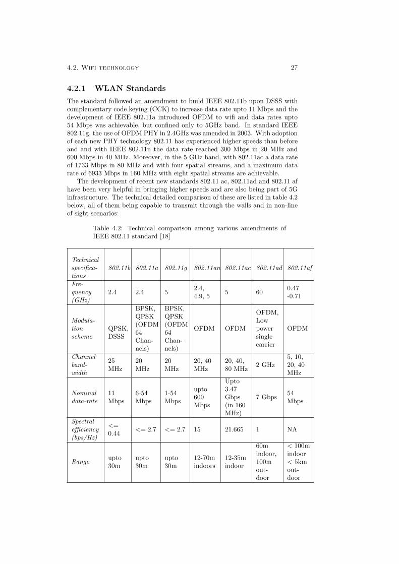
4.2.1 WLAN Standards
The standard followed an amendment to build IEEE 802.11b upon DSSS withcomplementary code keying (CCK) to increase data rate upto 11 Mbps and thedevelopment of IEEE 802.11a introduced OFDM to wifi and data rates upto54 Mbps was achievable, but confined only to 5GHz band. In standard IEEE802.11g, the use of OFDM PHY in 2.4GHz was amended in 2003. With adoptionof each new PHY technology 802.11 has experienced higher speeds than beforeand and with IEEE 802.11n the data rate reached 300 Mbps in 20 MHz and600 Mbps in 40 MHz. Moreover, in the 5 GHz band, with 802.11ac a data rateof 1733 Mbps in 80 MHz and with four spatial streams, and a maximum datarate of 6933 Mbps in 160 MHz with eight spatial streams are achievable.
The development of recent new standards 802.11 ac, 802.11ad and 802.11 afhave been very helpful in bringing higher speeds and are also being part of 5Ginfrastructure. The technical detailed comparison of these are listed in table 4.2below, all of them being capable to transmit through the walls and in non-lineof sight scenarios:
Table 4.2: Technical comparison among various amendments ofIEEE 802.11 standard [18]
Technicalspecifica-tions
802.11b 802.11a 802.11g 802.11an 802.11ac 802.11ad 802.11af
Fre-quency(GHz)
2.4 2.4 52.4,4.9, 5
5 600.47-0.71
Modula-tionscheme
QPSK,DSSS
BPSK,QPSK(OFDM64Chan-nels)
BPSK,QPSK(OFDM64Chan-nels)
OFDM OFDM
OFDM,Lowpowersinglecarrier
OFDM
Channelband-width
25MHz
20MHz
20MHz
20, 40MHz
20, 40,80 MHz
2 GHz5, 10,20, 40MHz
Nominaldata-rate
11Mbps
6-54Mbps
1-54Mbps
upto600Mbps
Upto3.47Gbps(in 160MHz)
7 Gbps54Mbps
Spectralefficiency(bps/Hz)
<=0.44
<= 2.7 <= 2.7 15 21.665 1 NA
Rangeupto30m
upto30m
upto30m
12-70mindoors
12-35mindoor
60mindoor,100mout-door
< 100mindoor< 5kmout-door
28 Chapter 4. Overview of Wireless communication
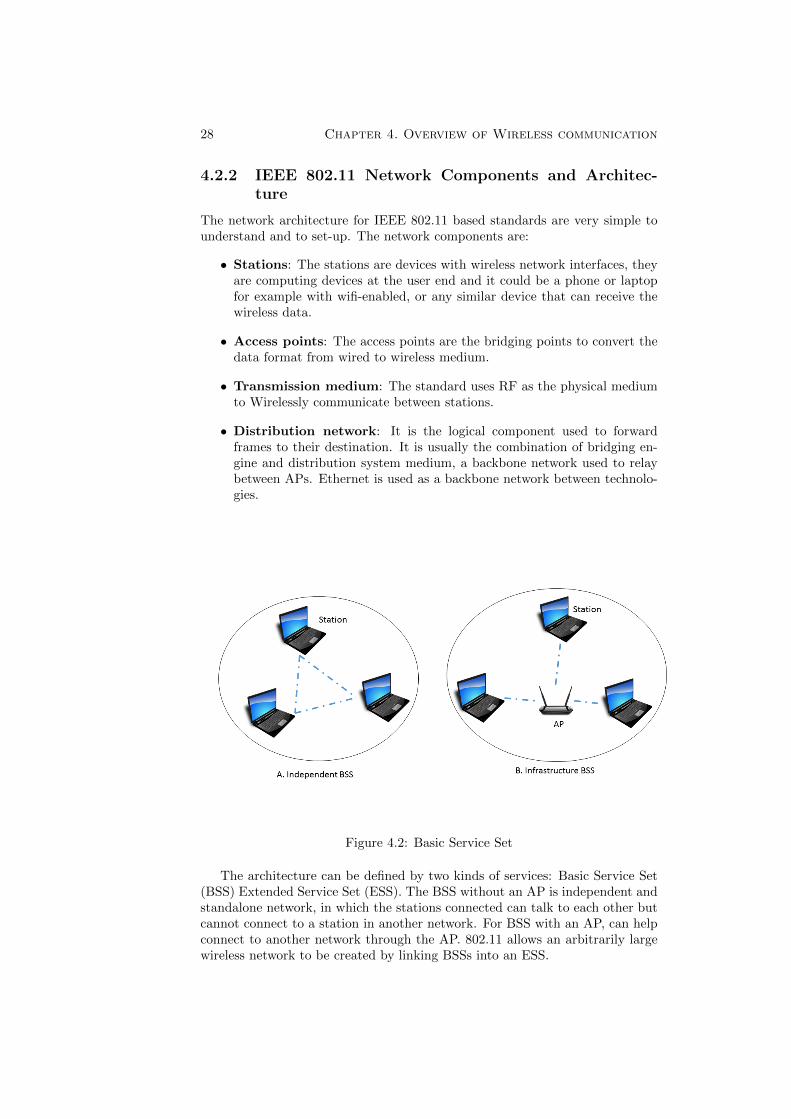
4.2.2 IEEE 802.11 Network Components and Architec-ture
The network architecture for IEEE 802.11 based standards are very simple tounderstand and to set-up. The network components are:
• Stations: The stations are devices with wireless network interfaces, theyare computing devices at the user end and it could be a phone or laptopfor example with wifi-enabled, or any similar device that can receive thewireless data.
• Access points: The access points are the bridging points to convert thedata format from wired to wireless medium.
• Transmission medium: The standard uses RF as the physical mediumto Wirelessly communicate between stations.
• Distribution network: It is the logical component used to forwardframes to their destination. It is usually the combination of bridging en-gine and distribution system medium, a backbone network used to relaybetween APs. Ethernet is used as a backbone network between technolo-gies.
Figure 4.2: Basic Service Set
The architecture can be defined by two kinds of services: Basic Service Set(BSS) Extended Service Set (ESS). The BSS without an AP is independent andstandalone network, in which the stations connected can talk to each other butcannot connect to a station in another network. For BSS with an AP, can helpconnect to another network through the AP. 802.11 allows an arbitrarily largewireless network to be created by linking BSSs into an ESS.
4.2. Wifi technology 29
Figure 4.3: Extended Service Set
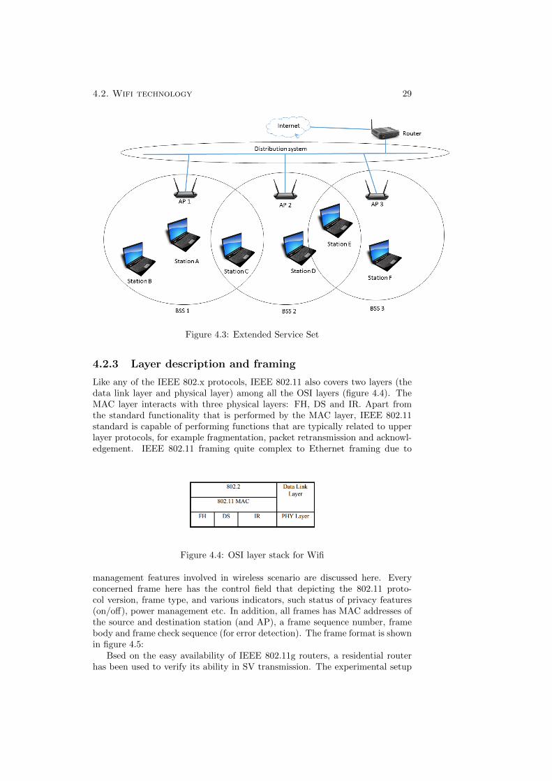
4.2.3 Layer description and framing
Like any of the IEEE 802.x protocols, IEEE 802.11 also covers two layers (thedata link layer and physical layer) among all the OSI layers (figure 4.4). TheMAC layer interacts with three physical layers: FH, DS and IR. Apart fromthe standard functionality that is performed by the MAC layer, IEEE 802.11standard is capable of performing functions that are typically related to upperlayer protocols, for example fragmentation, packet retransmission and acknowl-edgement. IEEE 802.11 framing quite complex to Ethernet framing due to
Figure 4.4: OSI layer stack for Wifi
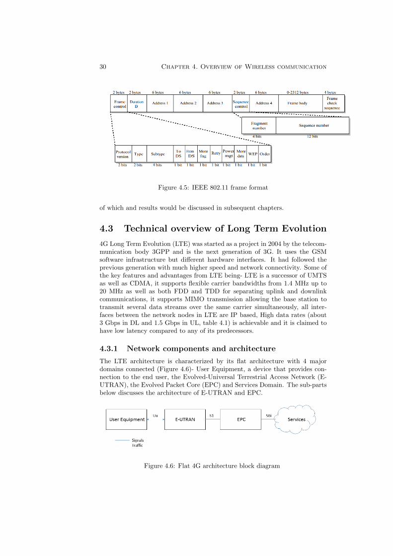
management features involved in wireless scenario are discussed here. Everyconcerned frame here has the control field that depicting the 802.11 proto-col version, frame type, and various indicators, such status of privacy features(on/off), power management etc. In addition, all frames has MAC addresses ofthe source and destination station (and AP), a frame sequence number, framebody and frame check sequence (for error detection). The frame format is shownin figure 4.5:
Bsed on the easy availability of IEEE 802.11g routers, a residential routerhas been used to verify its ability in SV transmission. The experimental setup
30 Chapter 4. Overview of Wireless communication
Figure 4.5: IEEE 802.11 frame format
of which and results would be discussed in subsequent chapters.
4.3 Technical overview of Long Term Evolution
4G Long Term Evolution (LTE) was started as a project in 2004 by the telecom-munication body 3GPP and is the next generation of 3G. It uses the GSMsoftware infrastructure but different hardware interfaces. It had followed theprevious generation with much higher speed and network connectivity. Some ofthe key features and advantages from LTE being- LTE is a successor of UMTSas well as CDMA, it supports flexible carrier bandwidths from 1.4 MHz up to20 MHz as well as both FDD and TDD for separating uplink and downlinkcommunications, it supports MIMO transmission allowing the base station totransmit several data streams over the same carrier simultaneously, all inter-faces between the network nodes in LTE are IP based, High data rates (about3 Gbps in DL and 1.5 Gbps in UL, table 4.1) is achievable and it is claimed tohave low latency compared to any of its predecessors.
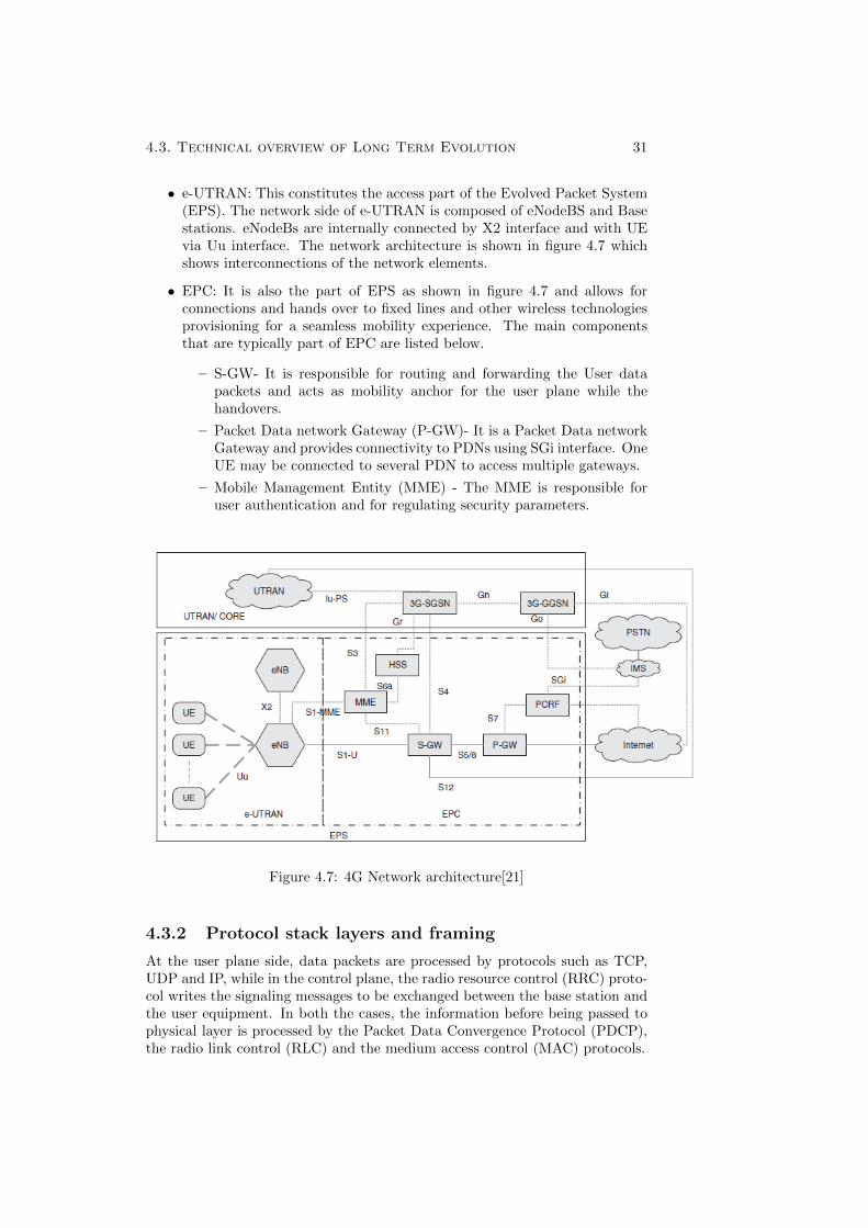
4.3.1 Network components and architecture
The LTE architecture is characterized by its flat architecture with 4 majordomains connected (Figure 4.6)- User Equipment, a device that provides con-nection to the end user, the Evolved-Universal Terrestrial Access Network (E-UTRAN), the Evolved Packet Core (EPC) and Services Domain. The sub-partsbelow discusses the architecture of E-UTRAN and EPC.
Figure 4.6: Flat 4G architecture block diagram
4.3. Technical overview of Long Term Evolution 31
• e-UTRAN: This constitutes the access part of the Evolved Packet System(EPS). The network side of e-UTRAN is composed of eNodeBS and Basestations. eNodeBs are internally connected by X2 interface and with UEvia Uu interface. The network architecture is shown in figure 4.7 whichshows interconnections of the network elements.
• EPC: It is also the part of EPS as shown in figure 4.7 and allows forconnections and hands over to fixed lines and other wireless technologiesprovisioning for a seamless mobility experience. The main componentsthat are typically part of EPC are listed below.
– S-GW- It is responsible for routing and forwarding the User datapackets and acts as mobility anchor for the user plane while thehandovers.
– Packet Data network Gateway (P-GW)- It is a Packet Data networkGateway and provides connectivity to PDNs using SGi interface. OneUE may be connected to several PDN to access multiple gateways.
– Mobile Management Entity (MME) - The MME is responsible foruser authentication and for regulating security parameters.
Figure 4.7: 4G Network architecture[21]
4.3.2 Protocol stack layers and framing
At the user plane side, data packets are processed by protocols such as TCP,UDP and IP, while in the control plane, the radio resource control (RRC) proto-col writes the signaling messages to be exchanged between the base station andthe user equipment. In both the cases, the information before being passed tophysical layer is processed by the Packet Data Convergence Protocol (PDCP),the radio link control (RLC) and the medium access control (MAC) protocols.
32 Chapter 4. Overview of Wireless communication
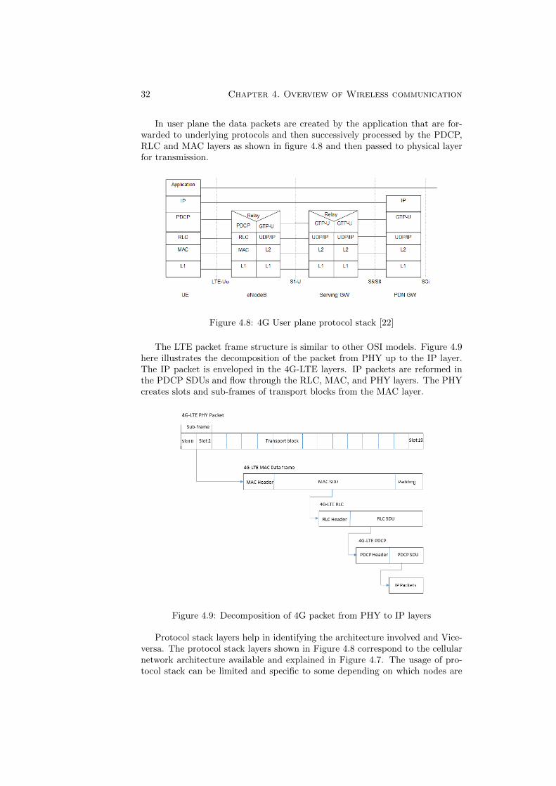
In user plane the data packets are created by the application that are for-warded to underlying protocols and then successively processed by the PDCP,RLC and MAC layers as shown in figure 4.8 and then passed to physical layerfor transmission.
Figure 4.8: 4G User plane protocol stack [22]
The LTE packet frame structure is similar to other OSI models. Figure 4.9here illustrates the decomposition of the packet from PHY up to the IP layer.The IP packet is enveloped in the 4G-LTE layers. IP packets are reformed inthe PDCP SDUs and flow through the RLC, MAC, and PHY layers. The PHYcreates slots and sub-frames of transport blocks from the MAC layer.
Figure 4.9: Decomposition of 4G packet from PHY to IP layers
Protocol stack layers help in identifying the architecture involved and Vice-versa. The protocol stack layers shown in Figure 4.8 correspond to the cellularnetwork architecture available and explained in Figure 4.7. The usage of pro-tocol stack can be limited and specific to some depending on which nodes are
4.4. The fifth generation of mobile networks 33
being used and is involved in the data transfer and communication. As later inSection 5.3 it could be seen that the experimental set-up involved in this Thesisis only the UE and eNodeB and thus, the protocol stack corresponding to thesetwo nodes are involved in communication.
4.4 The fifth generation of mobile networks
The very foundation of 5G lies on ten technologies- Machine Type Communi-cation (MTC), RAN Virtualization, millimeter (mm) wave, backhaul, evolvingRadio Access Technologies (RATs), energy efficiency, new spectrum, spectrumsharing, small cell and Self Operating Networks (SON). The 5G is being builtwith the aim of natively fulfilling the requirements of following use cases [21].
1. Massive Broadband (xMBB) with gigabytes of bandwidth on demand.
2. Massive Machine Type Communication (mMTC) connecting various sen-sors and machine.
3. Critical Machine Type Communication (uMTC) that allows immediatefeedback with high reliability.
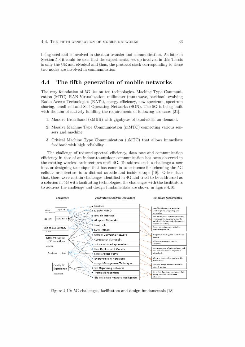
The challenge of reduced spectral efficiency, data rate and communicationefficiency in case of an indoor-to-outdoor communication has been observed inthe existing wireless architectures until 4G. To address such a challenge a newidea or designing technique that has come in to existence for scheming the 5Gcellular architecture is to distinct outside and inside setups [18]. Other thanthat, there were certain challenges identified in 4G and tried to be addressed asa solution in 5G with facilitating technologies, the challenges with the facilitatorsto address the challenge and design fundamentals are shown in figure 4.10.
Figure 4.10: 5G challenges, facilitators and design fundamentals [18]
34 Chapter 4. Overview of Wireless communication
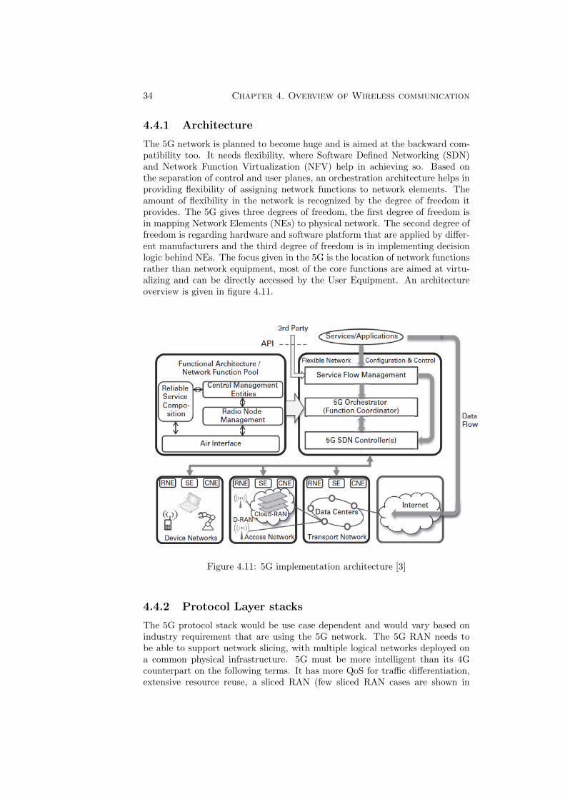
4.4.1 Architecture
The 5G network is planned to become huge and is aimed at the backward com-patibility too. It needs flexibility, where Software Defined Networking (SDN)and Network Function Virtualization (NFV) help in achieving so. Based onthe separation of control and user planes, an orchestration architecture helps inproviding flexibility of assigning network functions to network elements. Theamount of flexibility in the network is recognized by the degree of freedom itprovides. The 5G gives three degrees of freedom, the first degree of freedom isin mapping Network Elements (NEs) to physical network. The second degree offreedom is regarding hardware and software platform that are applied by differ-ent manufacturers and the third degree of freedom is in implementing decisionlogic behind NEs. The focus given in the 5G is the location of network functionsrather than network equipment, most of the core functions are aimed at virtu-alizing and can be directly accessed by the User Equipment. An architectureoverview is given in figure 4.11.
Figure 4.11: 5G implementation architecture [3]
4.4.2 Protocol Layer stacks
The 5G protocol stack would be use case dependent and would vary based onindustry requirement that are using the 5G network. The 5G RAN needs tobe able to support network slicing, with multiple logical networks deployed ona common physical infrastructure. 5G must be more intelligent than its 4Gcounterpart on the following terms. It has more QoS for traffic differentiation,extensive resource reuse, a sliced RAN (few sliced RAN cases are shown in
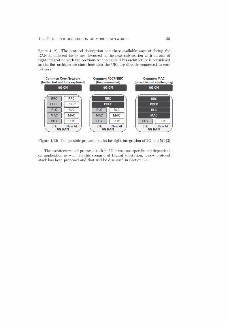
4.4. The fifth generation of mobile networks 35
figure 4.12). The protocol description and three available ways of slicing theRAN at different layers are discussed in the next sub section with an aim oftight integration with the previous technologies. This architecture is consideredas the flat architecture since here also the UEs are directly connected to corenetwork.
Figure 4.12: The possible protocol stacks for tight integration of 4G and 5G [3]
The architecture and protocol stack in 5G is use case specific and dependenton application as well. In this scenario of Digital substation, a new protocolstack has been proposed and that will be discussed in Section 5.4.

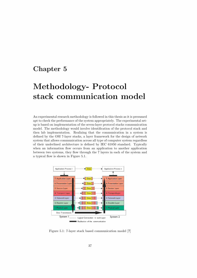
Chapter 5
Methodology- Protocolstack communication model
An experimental research methodology is followed in this thesis as it is presumedapt to check the performance of the system appropriately. The experimental set-up is based on implementation of the seven-layer protocol stacks communicationmodel. The methodology would involve identification of the protocol stack andthen lab implementation. Realizing that the communication in a system isdefined by the OSI 7-layer stacks, a layer framework for the design of networksystem that allows communication across all type of computer system regardlessof their underlined architecture is defined by IEC 61850 standard. Typicallywhen an information flow occurs from an application to another applicationbetween two systems, they flow through the 7 layers in each of the system anda typical flow is shown in Figure 5.1.
Figure 5.1: 7-layer stack based communication model [?]
37
38 Chapter 5. Methodology- Protocol stack communication model
5.1 Wired digital substation
The number of layers involved in communication may vary depending upon thetype and criticality of messages. In the standard IEC 61850 for the SubstationAutomation System, it identifies five communication protocols (as shown inFigure 3.5) at the application layer: SV, GOOSE and GSSE being the timecritical ones. The communication profiles of IEC 61850-9-2 standardizes forprocess bus SV. The communication services for it are mapped to protocolsstack layers of OSI and can be represented as in Figure 5.2.
5.1.1 Physical layer
The connection of merging unit to the secondary equipment can be an opticalfibre transmission system. Figure 5.2 mentions the suggested options on whatmedia to use.
5.1.2 Link layer
This layer being the second layer of the OSI model is responsible for data transferbetween adjacent node in Wide Area Network (WAN) and between the nodesof the same Local Area Network (LAN) segment.
• Ethernet addresses- The Ethernet broadcast addresses are used a defaultdestination address and thus no address configuration is needed at theconfiguration side.
• Priority tagging- The priority tagging is done according to the standardIEEE 802.1Q which is responsible for separating high priority protectionrelevant applications from the low priority busload.
• Ethertype: helps in identifying protocol encapsulated in the payload ofthe Ethernet frame.
5.1.3 Application layer
The Sampled Values for measuring Current and voltages from transformer areavailable in the raw data form, from the Merging Unit.
Rest of the layers are skipped as the Figure 5.2 shows the protocol stacklayers in existing digital substations based on IEC 61850.
The methodology for the integration of the IEEE 802.11g and 4G LTE release14 integration scenario with the process level of IEC 61850 based substation isexperimental and based on Communication model using protocol stacks. A set-up is implemented in a laboratory environment for the same. For 5G in digitalsubstation scenario an experimental simulation environment is set-up as the 5Gis in evolving stage and due to unavailability of an infrastructure for substation,simulation is the best suited environment to start with. The details of whichwould be discussed in subsequent sections. The details of the contents of SVdata and it’s packet frame can be referred from [25], which is the IEC 61850standard document defining SV.
The type and amount of data to be sent over the wireless network in theprocess level is identified, calculated and schematically represented in Figure5.3.
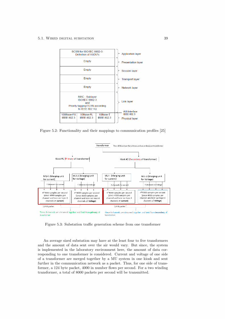
5.1. Wired digital substation 39
Figure 5.2: Functionality and their mappings to communication profiles [25]
Figure 5.3: Substation traffic generation scheme from one transformer
An average sized substation may have at the least four to five transformersand the amount of data sent over the air would vary. But since, the systemis implemented in the laboratory environment here, the amount of data cor-responding to one transformer is considered. Current and voltage of one sideof a transformer are merged together by a MU system in one kiosk and sentfurther in the communication network as a packet. Thus, for one side of trans-former, a 124 byte packet, 4000 in number flows per second. For a two windingtransformer, a total of 8000 packets per second will be transmitted.
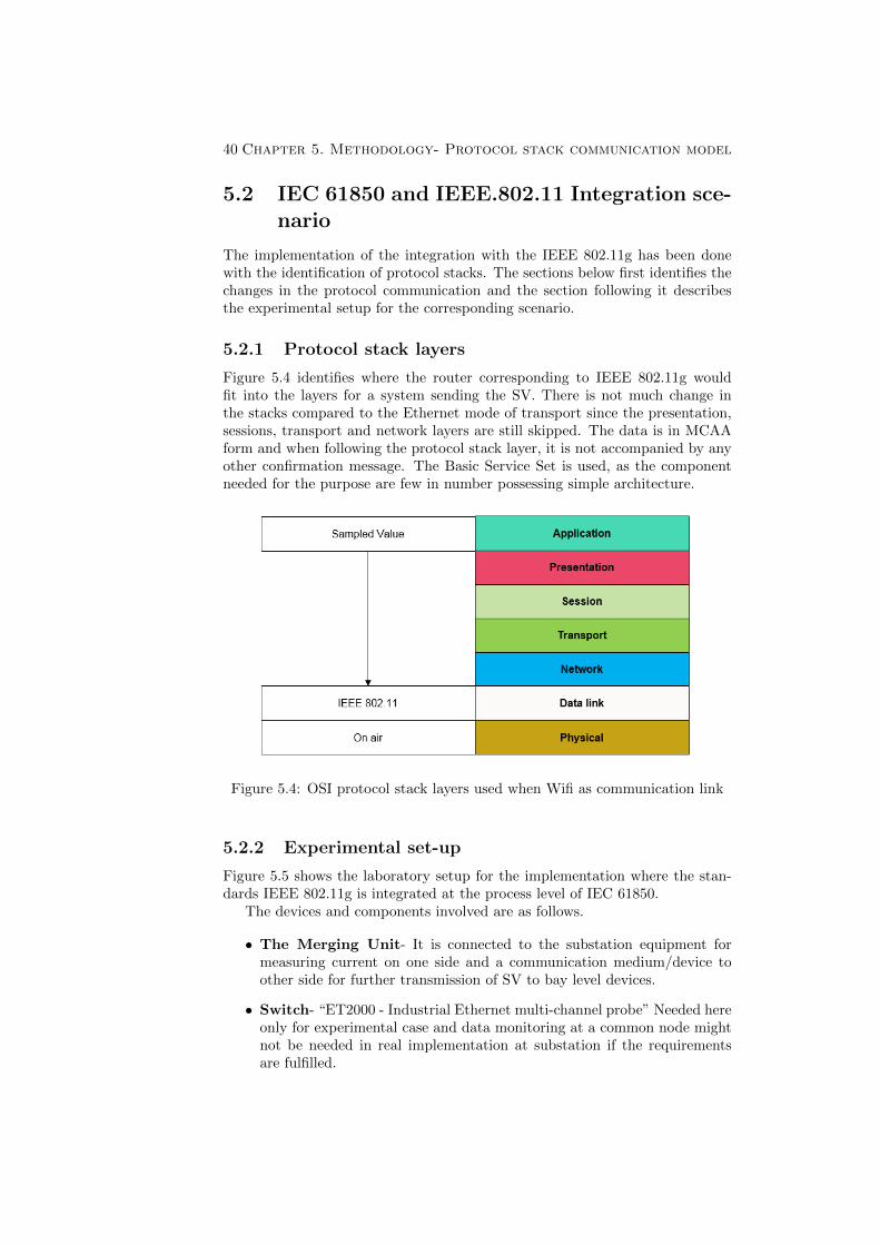
40 Chapter 5. Methodology- Protocol stack communication model
5.2 IEC 61850 and IEEE.802.11 Integration sce-nario
The implementation of the integration with the IEEE 802.11g has been donewith the identification of protocol stacks. The sections below first identifies thechanges in the protocol communication and the section following it describesthe experimental setup for the corresponding scenario.
5.2.1 Protocol stack layers
Figure 5.4 identifies where the router corresponding to IEEE 802.11g wouldfit into the layers for a system sending the SV. There is not much change inthe stacks compared to the Ethernet mode of transport since the presentation,sessions, transport and network layers are still skipped. The data is in MCAAform and when following the protocol stack layer, it is not accompanied by anyother confirmation message. The Basic Service Set is used, as the componentneeded for the purpose are few in number possessing simple architecture.
Figure 5.4: OSI protocol stack layers used when Wifi as communication link
5.2.2 Experimental set-up
Figure 5.5 shows the laboratory setup for the implementation where the stan-dards IEEE 802.11g is integrated at the process level of IEC 61850.
The devices and components involved are as follows.
• The Merging Unit- It is connected to the substation equipment formeasuring current on one side and a communication medium/device toother side for further transmission of SV to bay level devices.
• Switch- “ET2000 - Industrial Ethernet multi-channel probe” Needed hereonly for experimental case and data monitoring at a common node mightnot be needed in real implementation at substation if the requirementsare fulfilled.
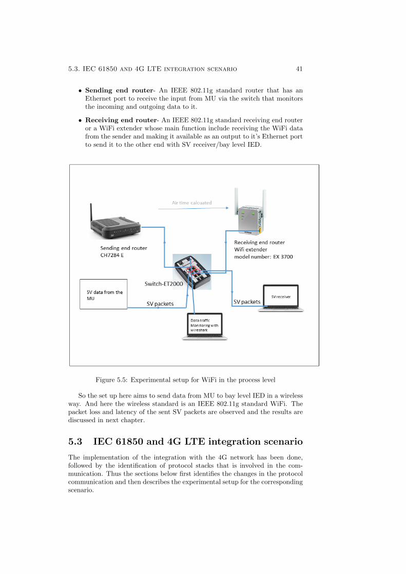
5.3. IEC 61850 and 4G LTE integration scenario 41
• Sending end router- An IEEE 802.11g standard router that has anEthernet port to receive the input from MU via the switch that monitorsthe incoming and outgoing data to it.
• Receiving end router- An IEEE 802.11g standard receiving end routeror a WiFi extender whose main function include receiving the WiFi datafrom the sender and making it available as an output to it’s Ethernet portto send it to the other end with SV receiver/bay level IED.
Figure 5.5: Experimental setup for WiFi in the process level
So the set up here aims to send data from MU to bay level IED in a wirelessway. And here the wireless standard is an IEEE 802.11g standard WiFi. Thepacket loss and latency of the sent SV packets are observed and the results arediscussed in next chapter.
5.3 IEC 61850 and 4G LTE integration scenario
The implementation of the integration with the 4G network has been done,followed by the identification of protocol stacks that is involved in the com-munication. Thus the sections below first identifies the changes in the protocolcommunication and then describes the experimental setup for the correspondingscenario.
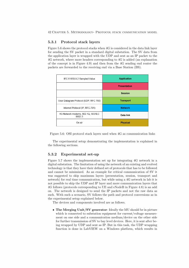
42 Chapter 5. Methodology- Protocol stack communication model
5.3.1 Protocol stack layers
Figure 5.6 shows the protocol stacks when 4G is considered in the data link layerfor sending the SV packet in a standard digital substation. The SV data fromthe application layer is wrapped with the UDP and sent as an IP packet to the4G network, where more headers corresponding to 4G is added (an explanationof the concept is in Figure 4.9) and then from the 4G sending end router thepackets are forwarded to the receiving end via a Base Station (BS).
Figure 5.6: OSI protocol stack layers used when 4G as communication links
The experimental setup demonstrating the implementation is explained inthe following sections.
5.3.2 Experimental set-up
Figure 5.7 shows the implementation set up for integrating 4G network in adigital substation. The limitation of using the network of an existing and evolvedtechnology is that they have their defined set of protocols that has to be followedand cannot be minimized. As an example for critical communication of SV itwas suggested to skip maximum layers (presentation, session, transport andnetwork) for real time communication, but while using a 4G network in lab it isnot possible to skip the UDP and IP layer and more communication layers that4G follows (protocols corresponding to UE and eNodeB in Figure 4.8) is an addon. The network is designed to send the IP packets and not the raw data assuch. With such a scenario, SV follows the path and protocol conversions as inthe experimental setup explained below.
The devices and components involved are as follows.
• The Merging Unit/SV generator- Ideally the MU should be in picturewhich is connected to substation equipment for current/voltage measure-ment on one side and a communication medium/device on the other sidefor further transmission of SV to bay level devices. Here, it is sent after be-ing wrapped by UDP and sent as IP. But in this task, the UDP wrappingfunction is done in LabVIEW on a Windows platform, which results in
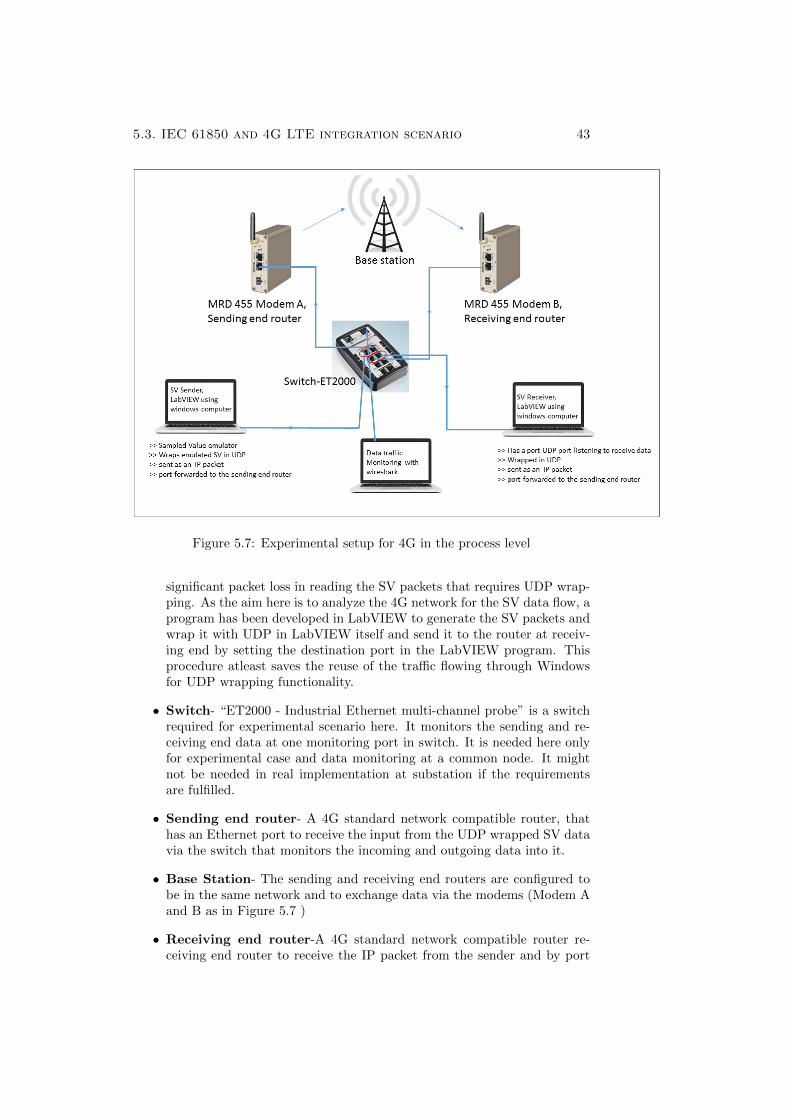
5.3. IEC 61850 and 4G LTE integration scenario 43
Figure 5.7: Experimental setup for 4G in the process level
significant packet loss in reading the SV packets that requires UDP wrap-ping. As the aim here is to analyze the 4G network for the SV data flow, aprogram has been developed in LabVIEW to generate the SV packets andwrap it with UDP in LabVIEW itself and send it to the router at receiv-ing end by setting the destination port in the LabVIEW program. Thisprocedure atleast saves the reuse of the traffic flowing through Windowsfor UDP wrapping functionality.
• Switch- “ET2000 - Industrial Ethernet multi-channel probe” is a switchrequired for experimental scenario here. It monitors the sending and re-ceiving end data at one monitoring port in switch. It is needed here onlyfor experimental case and data monitoring at a common node. It mightnot be needed in real implementation at substation if the requirementsare fulfilled.
• Sending end router- A 4G standard network compatible router, thathas an Ethernet port to receive the input from the UDP wrapped SV datavia the switch that monitors the incoming and outgoing data into it.
• Base Station- The sending and receiving end routers are configured tobe in the same network and to exchange data via the modems (Modem Aand B as in Figure 5.7 )
• Receiving end router-A 4G standard network compatible router re-ceiving end router to receive the IP packet from the sender and by port
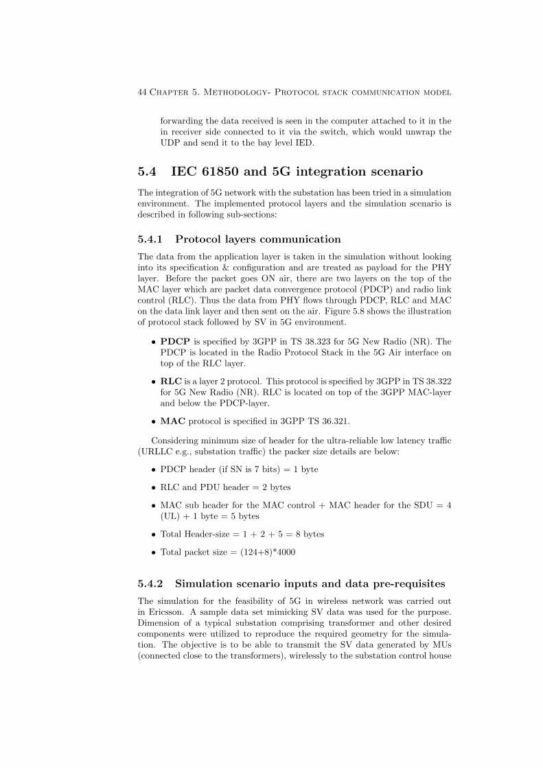
44 Chapter 5. Methodology- Protocol stack communication model
forwarding the data received is seen in the computer attached to it in thein receiver side connected to it via the switch, which would unwrap theUDP and send it to the bay level IED.
5.4 IEC 61850 and 5G integration scenario
The integration of 5G network with the substation has been tried in a simulationenvironment. The implemented protocol layers and the simulation scenario isdescribed in following sub-sections:
5.4.1 Protocol layers communication
The data from the application layer is taken in the simulation without lookinginto its specification & configuration and are treated as payload for the PHYlayer. Before the packet goes ON air, there are two layers on the top of theMAC layer which are packet data convergence protocol (PDCP) and radio linkcontrol (RLC). Thus the data from PHY flows through PDCP, RLC and MACon the data link layer and then sent on the air. Figure 5.8 shows the illustrationof protocol stack followed by SV in 5G environment.
• PDCP is specified by 3GPP in TS 38.323 for 5G New Radio (NR). ThePDCP is located in the Radio Protocol Stack in the 5G Air interface ontop of the RLC layer.
• RLC is a layer 2 protocol. This protocol is specified by 3GPP in TS 38.322for 5G New Radio (NR). RLC is located on top of the 3GPP MAC-layerand below the PDCP-layer.
• MAC protocol is specified in 3GPP TS 36.321.
Considering minimum size of header for the ultra-reliable low latency traffic(URLLC e.g., substation traffic) the packer size details are below:
• PDCP header (if SN is 7 bits) = 1 byte
• RLC and PDU header = 2 bytes
• MAC sub header for the MAC control + MAC header for the SDU = 4(UL) + 1 byte = 5 bytes
• Total Header-size = 1 + 2 + 5 = 8 bytes
• Total packet size = (124+8)*4000
5.4.2 Simulation scenario inputs and data pre-requisites
The simulation for the feasibility of 5G in wireless network was carried outin Ericsson. A sample data set mimicking SV data was used for the purpose.Dimension of a typical substation comprising transformer and other desiredcomponents were utilized to reproduce the required geometry for the simula-tion. The objective is to be able to transmit the SV data generated by MUs(connected close to the transformers), wirelessly to the substation control house
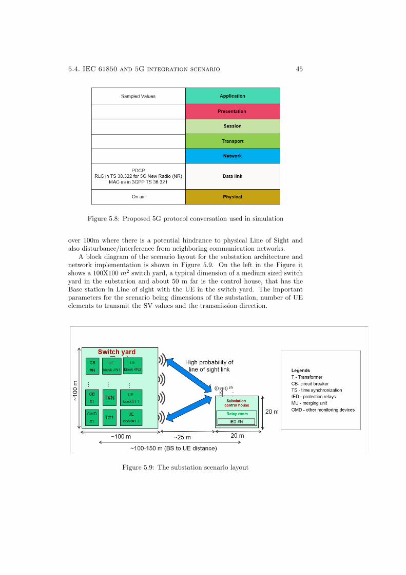
5.4. IEC 61850 and 5G integration scenario 45
Figure 5.8: Proposed 5G protocol conversation used in simulation
over 100m where there is a potential hindrance to physical Line of Sight andalso disturbance/interference from neighboring communication networks.
A block diagram of the scenario layout for the substation architecture andnetwork implementation is shown in Figure 5.9. On the left in the Figure itshows a 100X100 m2 switch yard, a typical dimension of a medium sized switchyard in the substation and about 50 m far is the control house, that has theBase station in Line of sight with the UE in the switch yard. The importantparameters for the scenario being dimensions of the substation, number of UEelements to transmit the SV values and the transmission direction.
Figure 5.9: The substation scenario layout
46 Chapter 5. Methodology- Protocol stack communication model
Table 5.1: Simulation scenario description
ScenarioDimension
100 m x 100 mSwitch yard: 100x100mDistance between switch yard and substationcontrol room: 50-100mSubstation control house: 50 m
TransmissionDirection
Up-link (UL) - Sampling value (SV)
Number ofnetworkelements
5 UE kiosks with up-link traffic 1 BS atsubstation control house
Table 5.1 gives an overview of substation dimension and layout. Table 5.2gives the details on the type of data that needs to be sent over the process busin 5G network. Thus, packet size described, latency and reliability requirementsposed by the network are also mentioned in Table 5.2.
Table 5.2: Data Traffic description
Parameter Value description/comment
SV Packet size 124 bytesContains 8 SVs perprimary or secondarytransformer
SV packetinter-arrival time
0.25 ms 4000 packets per second
SV interval time4 Mbps per UEkiosk
End to end latencydelay requirement
7 msFor radio access networklatency boundary = 3 ms
Reliabilityrequirement
Loss of no morethan 1 packet ina row
upto every second packetcan be lost
5.4.3 Simulation assumptions
The simulation done here is not the most realistic scenario but an idealisticone, with consideration of certain assumptions. The first assumption is that thesubstation is in an isolated environment where interference from local users ofmobile and telecom traffic is negligible. Also a layout has been proposed with theassumption of minimized interference from enhanced Mobile Broadband users(eMBB) user and simulated in the presence of random blockers and placementsof Kiosks in random locations.
Figure 5.10 shows the simulated view of such a substation Layout.in In-terference isolated scenario. The 100m x 100m substation is surrounded by aprohibited area which is 50 m wide. It also shows a simulated example of therandom distributed blockers and the SV data that from now on would be calledUltra Reliable Low Latency Communication (URLLC) data.
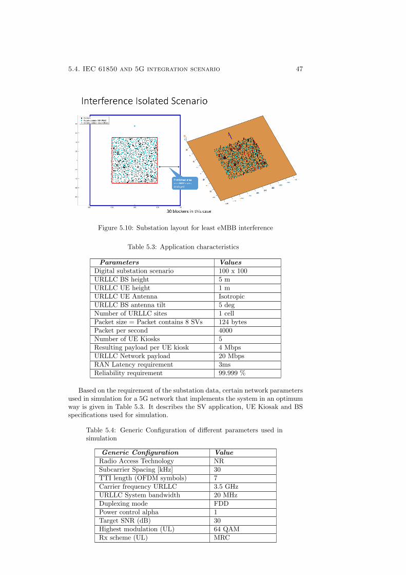
5.4. IEC 61850 and 5G integration scenario 47
Figure 5.10: Substation layout for least eMBB interference
Table 5.3: Application characteristics
Parameters ValuesDigital substation scenario 100 x 100
URLLC BS height 5 m
URLLC UE height 1 mURLLC UE Antenna Isotropic
URLLC BS antenna tilt 5 deg
Number of URLLC sites 1 cell
Packet size = Packet contains 8 SVs 124 bytes
Packet per second 4000Number of UE Kiosks 5
Resulting payload per UE kiosk 4 Mbps
URLLC Network payload 20 Mbps
RAN Latency requirement 3ms
Reliability requirement 99.999 %
Based on the requirement of the substation data, certain network parametersused in simulation for a 5G network that implements the system in an optimumway is given in Table 5.3. It describes the SV application, UE Kiosak and BSspecifications used for simulation.
Table 5.4: Generic Configuration of different parameters used insimulation
Generic Configuration ValueRadio Access Technology NR
Subcarrier Spacing [kHz] 30
TTI length (OFDM symbols) 7
Carrier frequency URLLC 3.5 GHz
URLLC System bandwidth 20 MHz
Duplexing mode FDDPower control alpha 1
Target SNR (dB) 30
Highest modulation (UL) 64 QAM
Rx scheme (UL) MRC
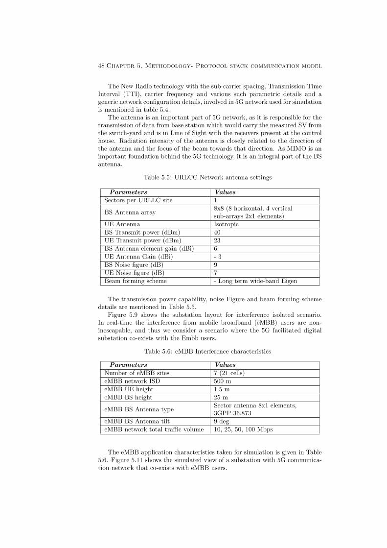
48 Chapter 5. Methodology- Protocol stack communication model
The New Radio technology with the sub-carrier spacing, Transmission TimeInterval (TTI), carrier frequency and various such parametric details and ageneric network configuration details, involved in 5G network used for simulationis mentioned in table 5.4.
The antenna is an important part of 5G network, as it is responsible for thetransmission of data from base station which would carry the measured SV fromthe switch-yard and is in Line of Sight with the receivers present at the controlhouse. Radiation intensity of the antenna is closely related to the direction ofthe antenna and the focus of the beam towards that direction. As MIMO is animportant foundation behind the 5G technology, it is an integral part of the BSantenna.
Table 5.5: URLCC Network antenna settings
Parameters ValuesSectors per URLLC site 1
BS Antenna array8x8 (8 horizontal, 4 verticalsub-arrays 2x1 elements)
UE Antenna Isotropic
BS Transmit power (dBm) 40
UE Transmit power (dBm) 23
BS Antenna element gain (dBi) 6UE Antenna Gain (dBi) - 3
BS Noise figure (dB) 9
UE Noise figure (dB) 7
Beam forming scheme - Long term wide-band Eigen
The transmission power capability, noise Figure and beam forming schemedetails are mentioned in Table 5.5.
Figure 5.9 shows the substation layout for interference isolated scenario.In real-time the interference from mobile broadband (eMBB) users are non-inescapable, and thus we consider a scenario where the 5G facilitated digitalsubstation co-exists with the Embb users.
Table 5.6: eMBB Interference characteristics
Parameters ValuesNumber of eMBB sites 7 (21 cells)
eMBB network ISD 500 m
eMBB UE height 1.5 m
eMBB BS height 25 m
eMBB BS Antenna typeSector antenna 8x1 elements,3GPP 36.873
eMBB BS Antenna tilt 9 deg
eMBB network total traffic volume 10, 25, 50, 100 Mbps
The eMBB application characteristics taken for simulation is given in Table5.6. Figure 5.11 shows the simulated view of a substation with 5G communica-tion network that co-exists with eMBB users.
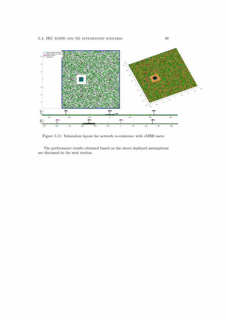
5.4. IEC 61850 and 5G integration scenario 49
Figure 5.11: Substation layout for network co-existence with eMBB users
The performance results obtained based on the above deployed assumptionsare discussed in the next section.

Chapter 6
Results and Discussion
This section discusses the network performance results of three different wirelessnetwork configuration based on lab experiments and/or simulations in terms ofpacket loss and latency calculation under specific conditions that are mentionedaccordingly.
6.1 IEEE 802.11 Performance evaluation on pro-cess bus
The EPC2425 Cisco router is a residential gateway router complying with IEEE802.11g standard. The experiment was conducted in an isolated environmentwhere the communication interference from other networks were not present.When the setup as explained in Figure 5.5 is established, the sampled valuescorresponding to one transformer data is sent from the merging unit whichcontained 8000 packets per second. The implementation of the protocol stackis verified by observing the protocol layers of the data on air and is given inthe snapshot below in Figure 6.1, obtained via Wireshark application in thecomputer.
Figure 6.1 shows the protocol stack layers captured for the data on air bya network analyzer. It verifies the successful implementation of the set-up thatwas aimed to achieve based on the communication protocol stack layers. Thedata on air consists of 142 bytes for each packet amongst which 124 bytes isdedicated for the SV data as payload for the WiFi link. The rest 18 bytescorresponds to Logical Link wrapping on IEEE 802.11. The protocol stacklayers highlighted in yellow in Figure 6.1 is thus similar to protocol stack aimedfor in Figure 5.4.
The sent data was verified at the sending end Ethernet port with a tappingto computer with Wireshark and is plotted as packets per second against timein Figure 6.2.
The plot in Figure 6.2 shows the data from two sides of transformer and thusthe value corresponds to 8000 packets per second. The data is received at thereceiving end device complying with IEEE 802.11g WiFi standard is producedin the plot in Figure 6.3.
From the two plots in Figures 6.2 and 6.3, a significant amount of loss couldbe observed. One in every 40 packets is received in such a protocol, primarily
51
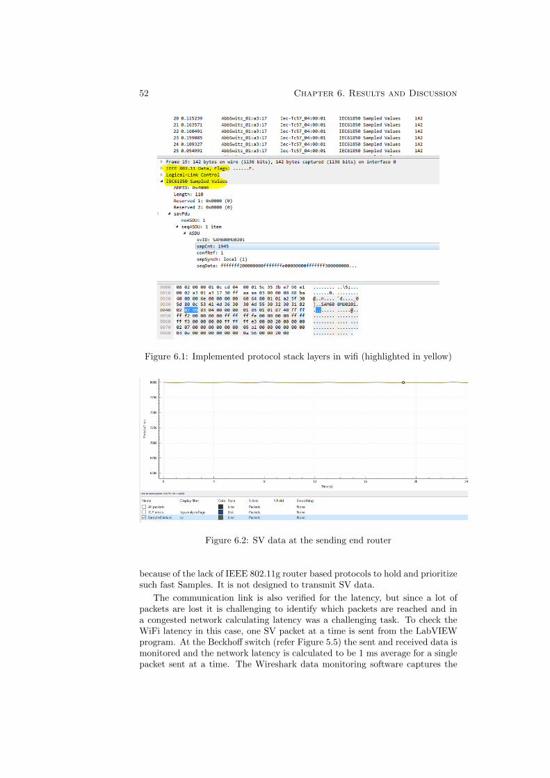
52 Chapter 6. Results and Discussion
Figure 6.1: Implemented protocol stack layers in wifi (highlighted in yellow)
Figure 6.2: SV data at the sending end router
because of the lack of IEEE 802.11g router based protocols to hold and prioritizesuch fast Samples. It is not designed to transmit SV data.
The communication link is also verified for the latency, but since a lot ofpackets are lost it is challenging to identify which packets are reached and ina congested network calculating latency was a challenging task. To check theWiFi latency in this case, one SV packet at a time is sent from the LabVIEWprogram. At the Beckhoff switch (refer Figure 5.5) the sent and received data ismonitored and the network latency is calculated to be 1 ms average for a singlepacket sent at a time. The Wireshark data monitoring software captures the
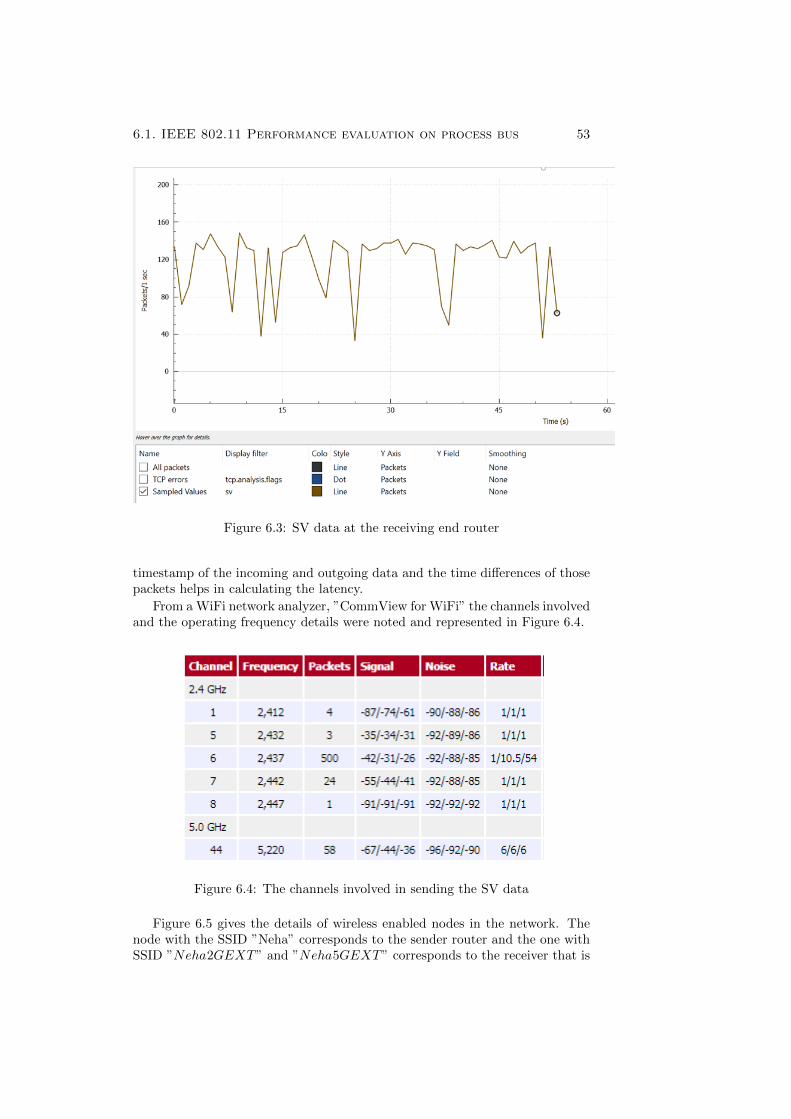
6.1. IEEE 802.11 Performance evaluation on process bus 53
Figure 6.3: SV data at the receiving end router
timestamp of the incoming and outgoing data and the time differences of thosepackets helps in calculating the latency.
From a WiFi network analyzer, ”CommView for WiFi” the channels involvedand the operating frequency details were noted and represented in Figure 6.4.
Figure 6.4: The channels involved in sending the SV data
Figure 6.5 gives the details of wireless enabled nodes in the network. Thenode with the SSID ”Neha” corresponds to the sender router and the one withSSID ”Neha2GEXT” and ”Neha5GEXT” corresponds to the receiver that is
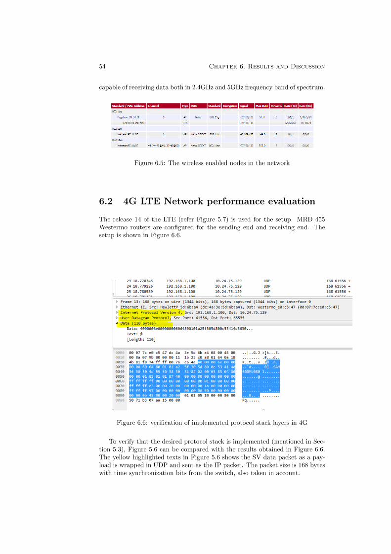
54 Chapter 6. Results and Discussion
capable of receiving data both in 2.4GHz and 5GHz frequency band of spectrum.
Figure 6.5: The wireless enabled nodes in the network
6.2 4G LTE Network performance evaluation
The release 14 of the LTE (refer Figure 5.7) is used for the setup. MRD 455Westermo routers are configured for the sending end and receiving end. Thesetup is shown in Figure 6.6.
Figure 6.6: verification of implemented protocol stack layers in 4G
To verify that the desired protocol stack is implemented (mentioned in Sec-tion 5.3), Figure 5.6 can be compared with the results obtained in Figure 6.6.The yellow highlighted texts in Figure 5.6 shows the SV data packet as a pay-load is wrapped in UDP and sent as the IP packet. The packet size is 168 byteswith time synchronization bits from the switch, also taken in account.
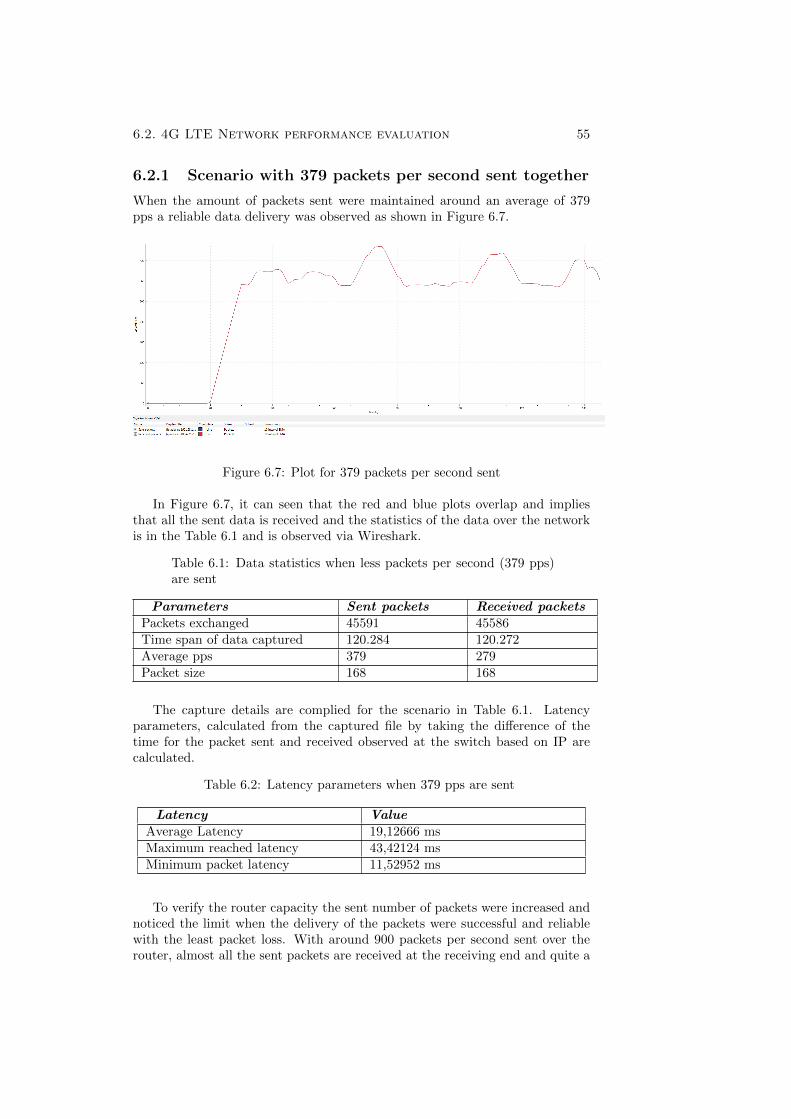
6.2. 4G LTE Network performance evaluation 55
6.2.1 Scenario with 379 packets per second sent together
When the amount of packets sent were maintained around an average of 379pps a reliable data delivery was observed as shown in Figure 6.7.
Figure 6.7: Plot for 379 packets per second sent
In Figure 6.7, it can seen that the red and blue plots overlap and impliesthat all the sent data is received and the statistics of the data over the networkis in the Table 6.1 and is observed via Wireshark.
Table 6.1: Data statistics when less packets per second (379 pps)are sent
Parameters Sent packets Received packetsPackets exchanged 45591 45586
Time span of data captured 120.284 120.272
Average pps 379 279
Packet size 168 168
The capture details are complied for the scenario in Table 6.1. Latencyparameters, calculated from the captured file by taking the difference of thetime for the packet sent and received observed at the switch based on IP arecalculated.
Table 6.2: Latency parameters when 379 pps are sent
Latency ValueAverage Latency 19,12666 ms
Maximum reached latency 43,42124 ms
Minimum packet latency 11,52952 ms
To verify the router capacity the sent number of packets were increased andnoticed the limit when the delivery of the packets were successful and reliablewith the least packet loss. With around 900 packets per second sent over therouter, almost all the sent packets are received at the receiving end and quite a
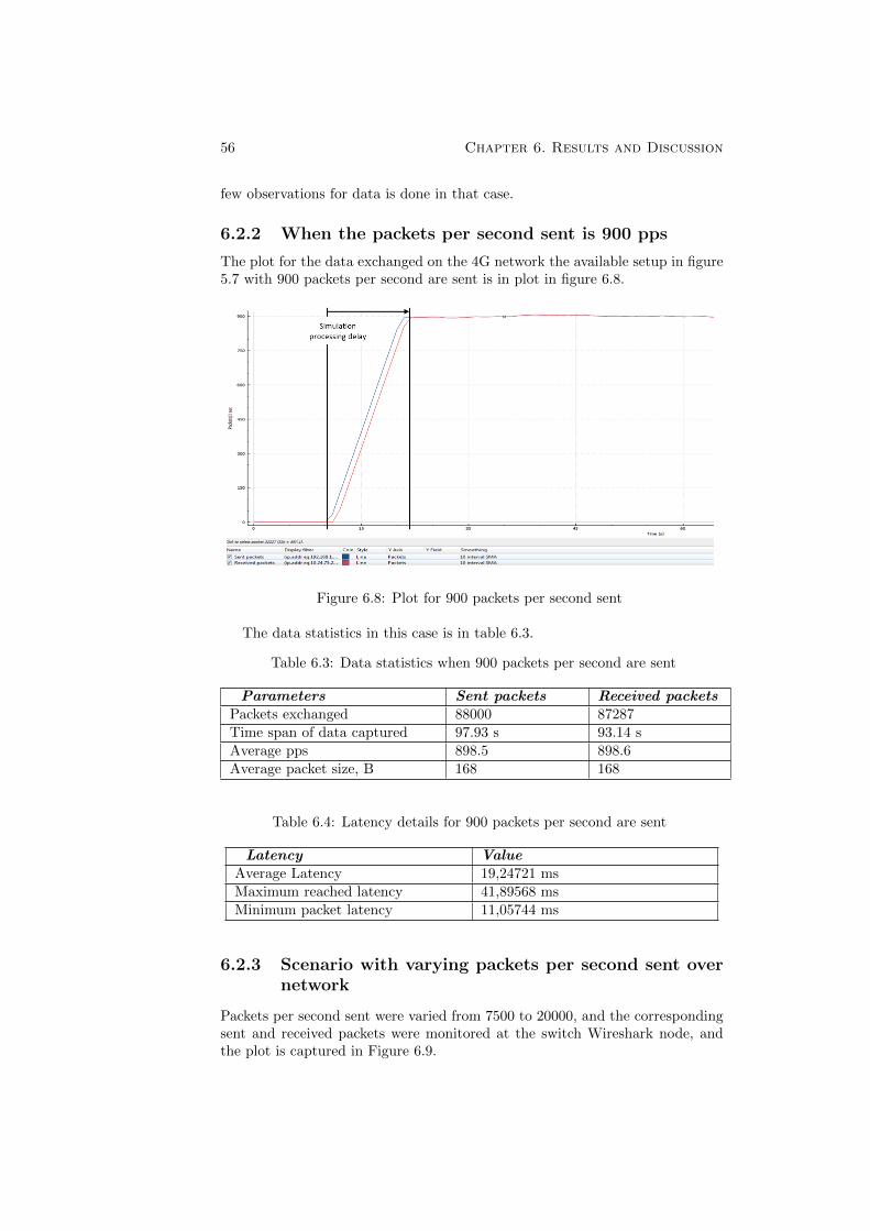
56 Chapter 6. Results and Discussion
few observations for data is done in that case.
6.2.2 When the packets per second sent is 900 pps
The plot for the data exchanged on the 4G network the available setup in figure5.7 with 900 packets per second are sent is in plot in figure 6.8.
Figure 6.8: Plot for 900 packets per second sent
The data statistics in this case is in table 6.3.
Table 6.3: Data statistics when 900 packets per second are sent
Parameters Sent packets Received packetsPackets exchanged 88000 87287
Time span of data captured 97.93 s 93.14 s
Average pps 898.5 898.6
Average packet size, B 168 168
Table 6.4: Latency details for 900 packets per second are sent
Latency ValueAverage Latency 19,24721 ms
Maximum reached latency 41,89568 ms
Minimum packet latency 11,05744 ms
6.2.3 Scenario with varying packets per second sent overnetwork
Packets per second sent were varied from 7500 to 20000, and the correspondingsent and received packets were monitored at the switch Wireshark node, andthe plot is captured in Figure 6.9.
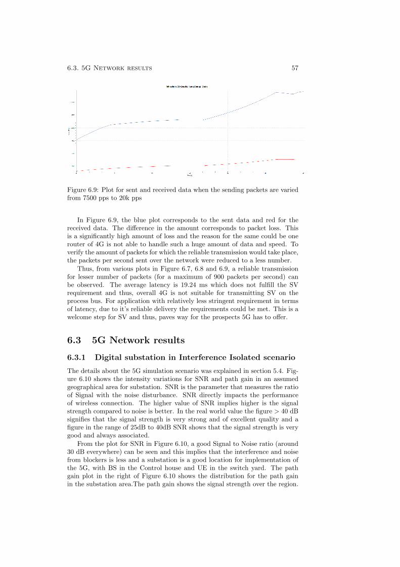
6.3. 5G Network results 57
Figure 6.9: Plot for sent and received data when the sending packets are variedfrom 7500 pps to 20k pps
In Figure 6.9, the blue plot corresponds to the sent data and red for thereceived data. The difference in the amount corresponds to packet loss. Thisis a significantly high amount of loss and the reason for the same could be onerouter of 4G is not able to handle such a huge amount of data and speed. Toverify the amount of packets for which the reliable transmission would take place,the packets per second sent over the network were reduced to a less number.
Thus, from various plots in Figure 6.7, 6.8 and 6.9, a reliable transmissionfor lesser number of packets (for a maximum of 900 packets per second) canbe observed. The average latency is 19.24 ms which does not fulfill the SVrequirement and thus, overall 4G is not suitable for transmitting SV on theprocess bus. For application with relatively less stringent requirement in termsof latency, due to it’s reliable delivery the requirements could be met. This is awelcome step for SV and thus, paves way for the prospects 5G has to offer.
6.3 5G Network results
6.3.1 Digital substation in Interference Isolated scenario
The details about the 5G simulation scenario was explained in section 5.4. Fig-ure 6.10 shows the intensity variations for SNR and path gain in an assumedgeographical area for substation. SNR is the parameter that measures the ratioof Signal with the noise disturbance. SNR directly impacts the performanceof wireless connection. The higher value of SNR implies higher is the signalstrength compared to noise is better. In the real world value the figure > 40 dBsignifies that the signal strength is very strong and of excellent quality and afigure in the range of 25dB to 40dB SNR shows that the signal strength is verygood and always associated.
From the plot for SNR in Figure 6.10, a good Signal to Noise ratio (around30 dB everywhere) can be seen and this implies that the interference and noisefrom blockers is less and a substation is a good location for implementation ofthe 5G, with BS in the Control house and UE in the switch yard. The pathgain plot in the right of Figure 6.10 shows the distribution for the path gainin the substation area.The path gain shows the signal strength over the region.
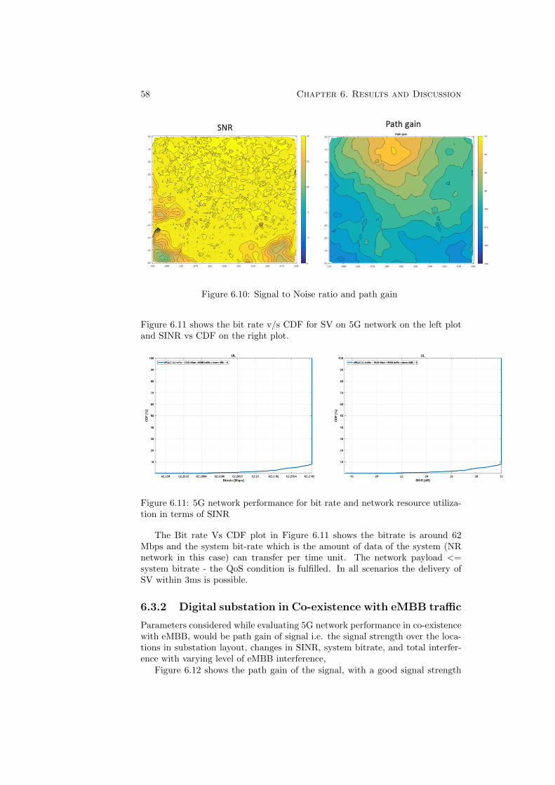
58 Chapter 6. Results and Discussion
Figure 6.10: Signal to Noise ratio and path gain
Figure 6.11 shows the bit rate v/s CDF for SV on 5G network on the left plotand SINR vs CDF on the right plot.
Figure 6.11: 5G network performance for bit rate and network resource utiliza-tion in terms of SINR
The Bit rate Vs CDF plot in Figure 6.11 shows the bitrate is around 62Mbps and the system bit-rate which is the amount of data of the system (NRnetwork in this case) can transfer per time unit. The network payload <=system bitrate - the QoS condition is fulfilled. In all scenarios the delivery ofSV within 3ms is possible.
6.3.2 Digital substation in Co-existence with eMBB traffic
Parameters considered while evaluating 5G network performance in co-existencewith eMBB, would be path gain of signal i.e. the signal strength over the loca-tions in substation layout, changes in SINR, system bitrate, and total interfer-ence with varying level of eMBB interference,
Figure 6.12 shows the path gain of the signal, with a good signal strength
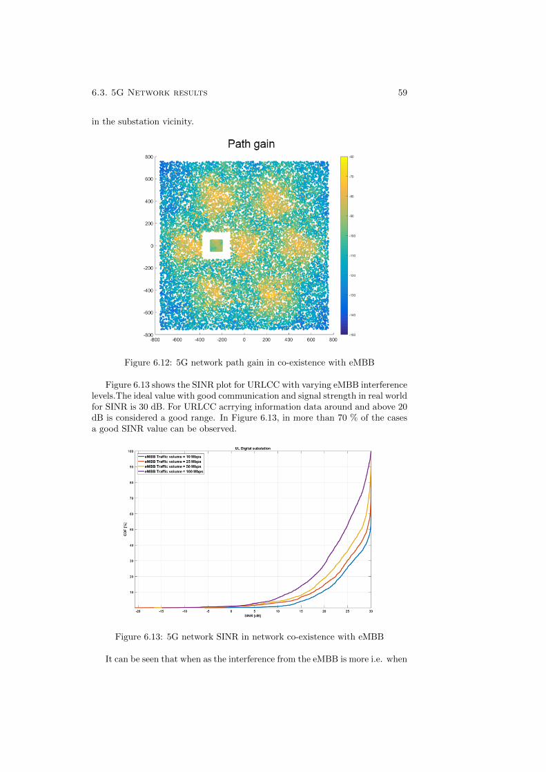
6.3. 5G Network results 59
in the substation vicinity.
Figure 6.12: 5G network path gain in co-existence with eMBB
Figure 6.13 shows the SINR plot for URLCC with varying eMBB interferencelevels.The ideal value with good communication and signal strength in real worldfor SINR is 30 dB. For URLCC acrrying information data around and above 20dB is considered a good range. In Figure 6.13, in more than 70 % of the casesa good SINR value can be observed.
Figure 6.13: 5G network SINR in network co-existence with eMBB
It can be seen that when as the interference from the eMBB is more i.e. when
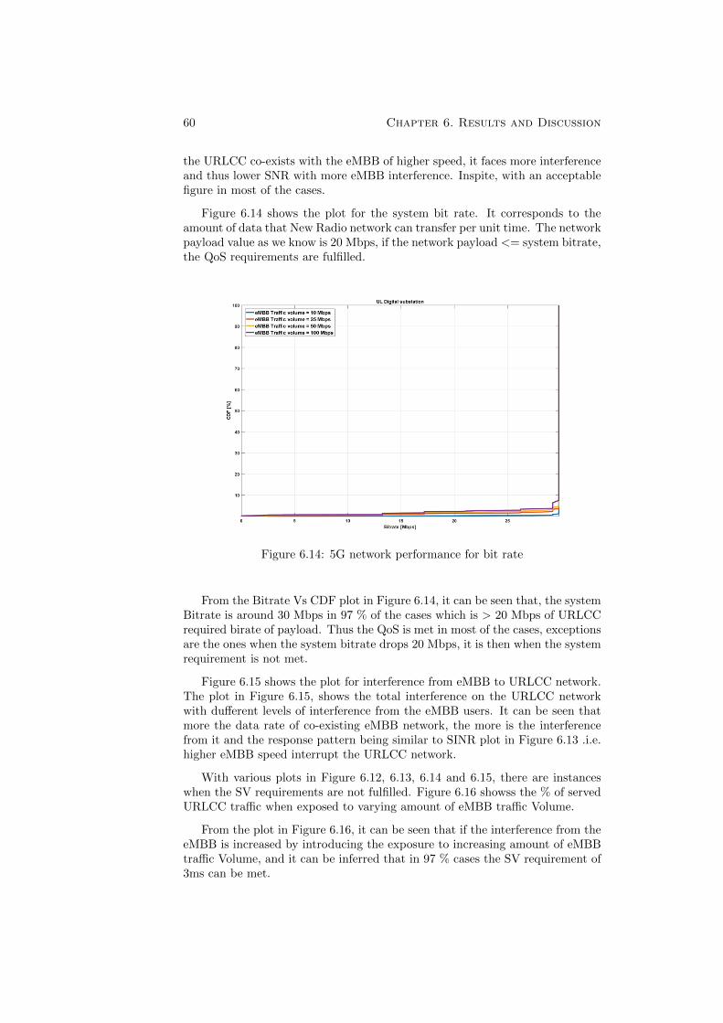
60 Chapter 6. Results and Discussion
the URLCC co-exists with the eMBB of higher speed, it faces more interferenceand thus lower SNR with more eMBB interference. Inspite, with an acceptablefigure in most of the cases.
Figure 6.14 shows the plot for the system bit rate. It corresponds to theamount of data that New Radio network can transfer per unit time. The networkpayload value as we know is 20 Mbps, if the network payload <= system bitrate,the QoS requirements are fulfilled.
Figure 6.14: 5G network performance for bit rate
From the Bitrate Vs CDF plot in Figure 6.14, it can be seen that, the systemBitrate is around 30 Mbps in 97 % of the cases which is > 20 Mbps of URLCCrequired birate of payload. Thus the QoS is met in most of the cases, exceptionsare the ones when the system bitrate drops 20 Mbps, it is then when the systemrequirement is not met.
Figure 6.15 shows the plot for interference from eMBB to URLCC network.The plot in Figure 6.15, shows the total interference on the URLCC networkwith dufferent levels of interference from the eMBB users. It can be seen thatmore the data rate of co-existing eMBB network, the more is the interferencefrom it and the response pattern being similar to SINR plot in Figure 6.13 .i.e.higher eMBB speed interrupt the URLCC network.
With various plots in Figure 6.12, 6.13, 6.14 and 6.15, there are instanceswhen the SV requirements are not fulfilled. Figure 6.16 showss the % of servedURLCC traffic when exposed to varying amount of eMBB traffic Volume.
From the plot in Figure 6.16, it can be seen that if the interference from theeMBB is increased by introducing the exposure to increasing amount of eMBBtraffic Volume, and it can be inferred that in 97 % cases the SV requirement of3ms can be met.
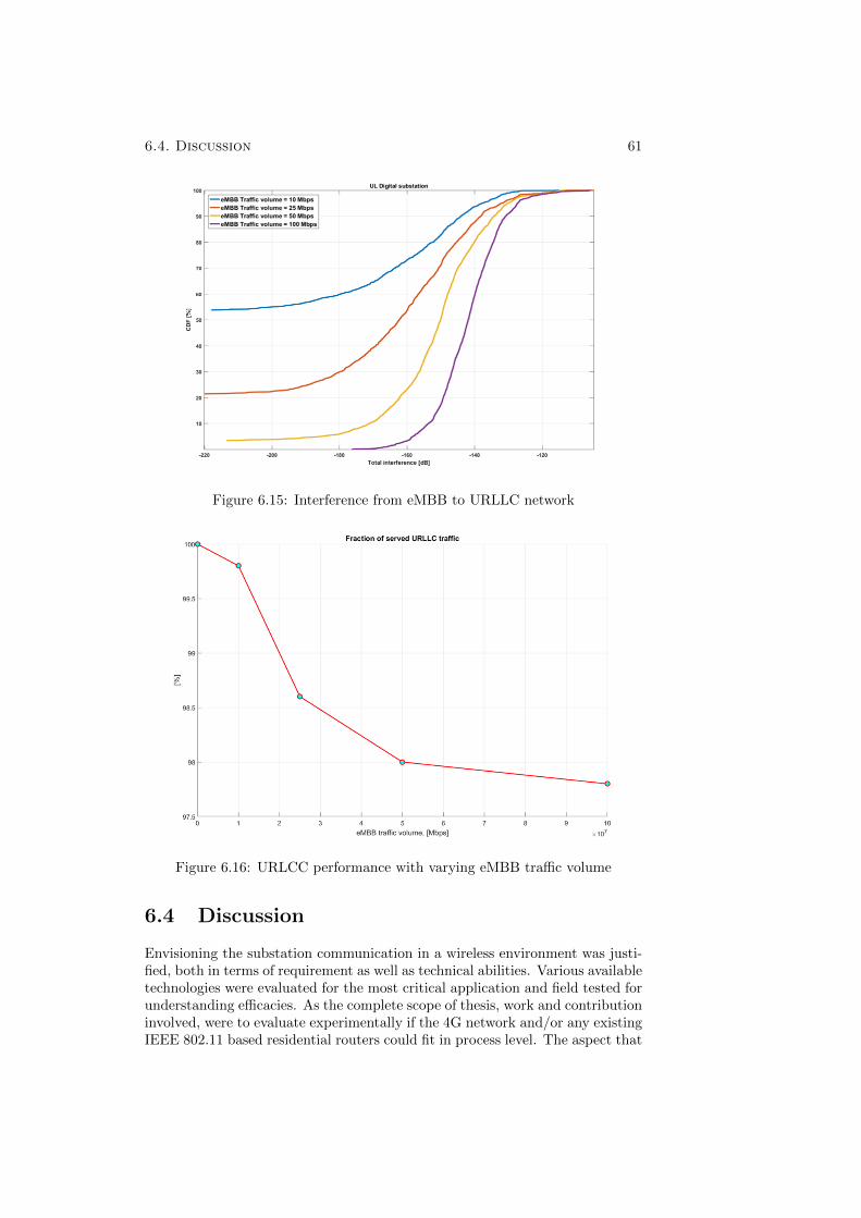
6.4. Discussion 61
Figure 6.15: Interference from eMBB to URLLC network
Figure 6.16: URLCC performance with varying eMBB traffic volume
6.4 Discussion
Envisioning the substation communication in a wireless environment was justi-fied, both in terms of requirement as well as technical abilities. Various availabletechnologies were evaluated for the most critical application and field tested forunderstanding efficacies. As the complete scope of thesis, work and contributioninvolved, were to evaluate experimentally if the 4G network and/or any existingIEEE 802.11 based residential routers could fit in process level. The aspect that
62 Chapter 6. Results and Discussion
help in evaluating the network for the same is the network latency and packetloss for the SV value over the communication networks. As per the literaturesurvey, sending SV on cellular network had not been tried and evaluated priorto this thesis. The report also tried to make use of the available industrial in-frastructure and thus, the available IEEE 802.11g residential router was usedfor verifying if it could satisfy the SV requirements on process level. Thoughthe results from the these available technologies were not entirely satisfying andthe results can be rightly useful. This also supported to look for the upcoming5G technology and the outcomes of 5G certainly show some promise. Hencethe deliverable of the thesis is believed to be a baby step towards adoptingintra-substation communication and is also believed to be a valuable contribu-tion in terms of engaging 5G for the non-obvious field, where it’s merits can betechnically more satisfying.
Chapter 7
Conclusion and FutureScope
This chapter discusses the conclusion of the thesis work and its future scope.The future scope is in terms of future tasks for the work done and in broad-wayfor the technology in specific.
7.1 Conclusion
Wireless technology are evolving and are finding applications in many emergingareas where stern communication feedback are desired. The compilation of mmwave, ultra-network speed, low latency amongst other features puts technologylike 5G on the forefront of communication advancement. However, 5G stillbeing on an evolving stage, it was worthwhile to investigate the parallel andpredecessor technology that are popular in this domain and could potentiallyoffer a competitive advantage over wired Ethernet framework.
With the above view, three major wireless technology were evaluated to un-derstand their suitability and applicability for addressing the SV traffic in adigital substation environment. This was considered to be an essential step,since SV traffic is the most critical and demanding application, requiring a re-sponse time of 3 ms for the protection functions, handled in a digital substation.Similarly, quality of service is another important parameter to reckon with. SVdata are multicast signals and expect a timely delivery, therefore attach a pri-ority tagging. This sampled signals, when sent over Ethernet- a multiple ofthem can be combined into a single frame and sent together. Understandingthe criticality of the involved signals, the wireless techniques are proposed as aredundant alterative to the IEC 618510 framework which is currently handledby another HSR or PRP mechanism. IEEE 802.11g wireless as well as 4G LTEwere tested in the laboratory condition to transmit the SV data from the MUstreams into the remote location, where the IEDs are expected to receive thesignal. The RAN latency was calculated for the time taken by the sending andreceiving end router to Trans-receive the available streams.
IEEE 802.11g resulted in an unassumingly huge packet loss compared to thesending cycle, thus obviating the possibility of using this technology for SV datatransmission. This is because WiFi keeps the data in queue until the network
63
64 Chapter 7. Conclusion and Future Scope
is available and re-transmits the data upon availability. 4G LTE achieved lim-ited success with noticeable acceptable round-trip latency of 19.25 ms for theSV data transmission. Up to 900 packets were gracefully transmitted withoutsignificant loss at the receiving end, exceeding which the lost packets were ex-ponentially outnumbered compared to sent packets. Even though this wirelesstechnology shows limitation of continuous streaming of SV data in a large scale,it simultaneously shows that if the number of packets are less, involving lessernumber of channels or windings or voltage/current parameter, it is still possibleto use this technology for a faithful transmission, if the transmission delay of19.25 ms is an acceptable range.
On the contrary, significant lead was achieved during simulations, for trans-mitting the SV streams in a 5G environment where the substation dimensions,blockers, physical object locations, line of sight etc. were mimicked, based on anear accurate geometrical representation of a substation. A very high degree ofSNR and path gain was obtained despite the presence of mobile network in thevicinity. The latency was within the desired range of 3 ms.
7.2 Future scope
The task done in the thesis is at a very primitive stage and thus carries a lot offuture task, In case of WLAN, it was verified that, the IEEE 802.11g standardbased residential routers were un-suitable for sending SV streams. But lookingat the communication protocol stack for IEEE 802.11 standard as a whole, itshows an efficient way to send the data by minimizing the latency over air, whichis true for lesser packets for SV over the air. Future task for this would includea research and investigation on what is lacking in IEEE 802.11g in making it asa reliable connection. Probably such a technology can be modified specific toSV nature, and prioritizing such streams.
4G LTE release 14, a stand alone Base station, not commercially availablebut developed by Ericsson has been used. The limitation of the specific taskis that an existing set-up of base station is used that involves two hops overthe air and thus an increased network latency. To seriously evaluate the bestof 4G LTE, a simulation of 4G LTE network can be done, where the BS at theMU send the data to wireless IED devices and that could probably be the bestutilization of 4G offerings.
5G simulations done in the thesis on the other hand is a positive result forsubstation communication and encourages further to confirm the implementa-tion. The approach can vary and the next steps possibly can involve implement-ing such communication in an existing substation. It would require developingthe hardware that can read from MU and with the functions enabled to prior-itize SV value, could send to wireless enabled IEDs. The further scope to lookinto would be the security, the electromagnetic interference and further dataanalysis.
”5G is more about providing the services people need at the appropriatequality of service,” are the word from Marcus Weldon, CTO Alcatel-Lucent’swireline-networks product division. With the rise of machines, it is importantto match the right speed with right application. 5G addresses the networkconvergence by the network slicing and sticking the various access technologiestogether. The flexible and open network architecture of 5G provides indepen-
7.2. Future scope 65
dent operation capabilities and make it application/ usecase specific. Unlikethe previous generation of telecom technologies 5G does not focus on the net-work abilities, but rather on offering right abilities to right service. It is anopportunity for the telecom operators like AT&T, Telia, Swiss Telecom, KoreanTelephone company, Reliance Jio etc. to move beyond connectivity and collab-orate across sectors such as finance, transport, retail and health to deliver richservices. It is an opportunity for industries to advance their digital ambitions,with 5G acting as a catalyst to their innovation.
With the increasing dynamic requirements in the power industry equipment,it posses a need to have an information flow with a certain critical latency andspeed requirement. 5G with successful simulation results and with customizednetwork availability paves a way to see itself in substations in power industrycompeting with the existing network solution.

REFERENCES
[1] HP and Deloitte Join Forces for the Fourth Industrial Revolution,https://www.engineering.com/AdvancedManufacturing/ArticleID/15530/HP-and-Deloitte-Join-Forces-for-the-Fourth-Industrial-Revolution.aspx, Imagecourtesy: Christoph Roser/AllAboutLean.com.
[2] Shigeru23 - Own work, CC BY-SA 3.0,https://commons.wikimedia.org/w/index.php?curid=14896493
[3] A Osseiran, J F. Monserrat, P Marsch (eds.). 5G Mobile and Wireless Com-munications Technology. Cambridge University Press (2016).
[4] J Schafer, Evolution of digital substation,http://primeraeng.com/posts/modern-substation/
[5] T. Buhagiar, Jean-Paul Cayuela, A. Procopiou, S. Richards, R. RamlachanSmart Substation For The French Power Grid, RTE France and GE Gridsolutions.
[6] IEC. IEC 61850 Part 1: Introduction and overview. 2002.
[7] IEC. IEC 61850 Part 5: Communication requirements for functions anddevice models. 2002.
[8] P. Castello, P. Ferrari, A. Flammini, C. Muscas, P. A. Pegoraro and S. Ri-naldi. A Distributed PMU for Electrical Substations With Wireless Redun-dant Process Bus. IEEE transactions on instrumentation and measurement,Vol. 64, no. 5, May 2015.
[9] R. Bucher, Smart grid functionality for the high-voltage transmission grid:On the market readiness of Digital Substation 2.0 technology. Lahmeyer In-ternational GmbH, Germany.
[10] C A Dutra, S L Zimath, J G Rolim Process Bus Reliability Analysis
[11] G. T. Pham, Dr. Georgios Karagiannis, Dr. G. Heijenk Prof. B. CampfensIntegration of IEC 61850 MMS and LTE to support smart metering com-munications, Masters thesis, University of Twente, 2013.
[12] D. Patel, M. I. N. Mohamed, S. Mehdi, F. Williams, A. Sadu, F. Ponci andA. Monti. Investigating the performance of QoS enabled LTE networks forIEC 61850 based smart grid applications. IEEE, 2016.
67
68 REFERENCES
[13] C. Kalalas, L. Gkatzikis, C. Fischione, P. Ljungberg, and J. A. Zarate. En-abling IEC 61850 Communication Services over Public LTE Infrastructure.IEEE ICC 2016 SAC Communications for the Smart Grid, 2016.
[14] N. H. Ali, B. Mohd Ali, O. Basir, M. L Othman, F. Hashim IEC 61850-based WLAN peer-to-peer feeder protection improvement in smart grid Sub-station Automation System, Journal of Theoretical and Applied InformationTechnology, 31st October 2015. Vol.80. No.3
[15] C. Shijie, S. Zhijun, and Z. Peng. Design and Implementation of the Wire-less Data Acquisition System for Substation Based on IEC 61850 and WIA-PA. Seventh International Conference on Measuring Technology and Mecha-tronics Automation, 2015.
[16] R.E. Mackiewicz Overview of IEC 61850 and benefits. Cambridge, U.K.:Cambridge Univ. Press, 2008.
[17] E. Perahia and R. Stacey Next Generation Wireless LANs: Throughput,Robustness, and Reliability in 802.11n, IEEE Transaction on Industrial In-formatics, 2012.
[18] A. Gupta, R. K. Jha A Survey of 5G Network: Architecture and EmergingTechnologies, 2169-3536 copyrights 2015 IEEE.
[19] IEC, IEC 61850 part 7-2 Ed. 2: Basic information and communicationstructure- Abstract Communication Service Interface (ACSI), 2008.
[20] P. Parikh, T S. Sidhu, A. Shami, J. Jiang, R. Sobot, M. Ray and K. Bhat-tacharya Investigation of Wireless LAN for IEC 61850 based Smart Distri-bution Substations, IEEE Transaction on Industrial Informatics, 2012.
[21] L. Korowajczuk-LTEWiMAX and WLAN Network Design, Optimizationand Performance Analysis, John Wiley and Sons (2011).
[22] S. Sesia, I. Toufik and M. Baker LTE: The The UMTS Long Term Evolutionfrom theory to practice, John Wiley and Sons (2009).
[23] ABB Digital substation brochure, ”Digital substations Enabling a stronger,smarter and greener grid”, Copyright 2016 ABB.
[24] IEC. IEC 61850 Part 8-1: Specific Communication Service Mapping(SCSM) - Mappings to MMS (ISO 9506-1 and ISO 9506-2) and to ISO/IEC8802-3. 2004.
[25] IEC. IEC 61850 Part 9-2 Ed.2: Part 9-2: Specific Communication ServiceMapping (SCSM) - Sampled values over ISO/IEC 8802-3. 2009.
[26] IEC. IEC 61850-90-5 TR Ed.1: Communication networks and systems forpower utility automation - Part 90-5: Use of IEC 61850 to transmit syn-chrophasor information according to IEEE C37.118. 2011.
[27] P. Parikh, M. G. Kanabar, and T. S. Sidhu. Opportunities and Challenges ofWireless Communication Technologies for Smart Grid Applications. IEEE,2010.
REFERENCES 69
[28] 5G partnership projects listed https://5g-ppp.eu/5g-ppp-phase-1-projects/
[29] C A Dutra, S L Zimath, J G Rolim Process Bus Reliability Analysis.

TRITA -EECS-EX-2018:566
www.kth.se


![MlV]H - IRC · 'Governance' - Nanda Abeywickrama 2c. ... problems of global water scarcity. ... Sanitation Non-revenue water](https://img.pdfslide.net/doc/110x75/5b53fff37f8b9a45298c6fe8/mlvh-irc-governance-nanda-abeywickrama-2c-problems-of-global-water.jpg)


![Sincere Salad Dressing[4]](https://img.pdfslide.net/doc/110x75/55d5232dbb61eb74118b4588/sincere-salad-dressing4.jpg)