Embed Size (px)
Citation preview
April 3, 2019
FEASIBILITY STUDY REPORT Northrop Grumman Bethpage Facility (Operable Units 2 and 3)
& Naval Weapons Industrial Reserve Plant (Operable Unit 2)
(NYSDEC Site # 130003A and 130003B)
NYSDEC STANDBY ENGINEERING CONTRACT Work Assignment # D007625-32
PREPARED FOR
NEW YORK STATE DEPARTMENT OF ENVIRONMENTAL CONSERVATION 625 BROADWAY
ALBANY, NEW YORK 12233
Prepared by
16 Corporate Woods Blvd.
Albany, NY 12211
Department of Environmental Conservation

Northrop Grumman – Bethpage Facility/Naval Weapons Industrial Reserve Plant i Feasibility Study Report April 3, 2019
Table of Contents
EXECUTIVE SUMMARY
1 INTRODUCTION ................................................................................................................ 1
2 SITE DESCRIPTION AND HISTORY ................................................................................. 2
2.1 General Site Description ........................................................................................... 2
2.2 Operable Units ........................................................................................................... 2
2.2.1 Operable Unit 1 ..................................................................................................... 3
2.2.1.1 Northrop Grumman Bethpage Facility ............................................................ 3
2.2.1.2 Naval Weapons Industrial Reserve Plant ....................................................... 3
2.2.2 Operable Unit 2 ..................................................................................................... 4
2.2.3 Operable Unit 3 ..................................................................................................... 5
2.3 Site-Related Contaminants of Concern .................................................................... 6
2.4 Applicable Standards, Criteria, and Guidance ......................................................... 8
2.4.1 Chemical-Specific SCGs ....................................................................................... 9
2.4.2 Location-Specific SCGs ........................................................................................ 9
2.4.3 Action-Specific SCGs ...........................................................................................10
2.4.4 Summary of Standards, Criteria, and Guidance ...................................................10
2.5 Physical Setting ........................................................................................................10
2.5.1 Topography .........................................................................................................10
2.5.2 Surface Water ......................................................................................................11
2.5.3 Geology ...............................................................................................................12
2.5.4 Hydrogeology.......................................................................................................13
3 REMEDIAL INVESTIGATION SUMMARY ........................................................................15
3.1 Previous Remedial Investigation Summary ............................................................15
3.2 2017-18 Supplemental Remedial Investigation Summary ......................................15
3.3 Database Compilation ..............................................................................................17
3.4 Groundwater Visualization .......................................................................................19
3.5 Groundwater Flow Modeling ....................................................................................20
3.5.1 Focus Area Model ................................................................................................20
3.5.2 Simulating the Potential Affects to the Environment .............................................22
3.5.2.1 Surface Water ...............................................................................................23
3.5.2.2 Wetlands .......................................................................................................23
3.5.2.3 Public Water Supply Wells ............................................................................24
3.5.2.4 Saltwater Intrusion ........................................................................................24
Northrop Grumman – Bethpage Facility/Naval Weapons Industrial Reserve Plant ii Feasibility Study Report April 3, 2019
3.6 Nature and Extent of Groundwater Contamination ................................................25
4 REMEDIAL GOALS AND REMEDIAL ACTION OBJECTIVES.........................................29
4.1 Remedial Goals .........................................................................................................29
4.2 Remedial Action Objectives .....................................................................................29
5 GENERAL RESPONSE ACTIONS ....................................................................................30
5.1 No Further Action .....................................................................................................30
5.2 Institutional Controls with Long-Term Monitoring .................................................31
5.3 MNA with Long-Term Monitoring .............................................................................31
5.4 Containment ..............................................................................................................31
5.5 In-situ Treatment .......................................................................................................32
5.6 Ex-situ Treatment ......................................................................................................32
5.7 Groundwater Disposal/Discharge ............................................................................32
6 IDENTIFICATION AND SCREENING OF TECHNOLOGIES ............................................34
6.1 No Further Action .....................................................................................................35
6.2 Institutional Controls and Long-Term Monitoring ..................................................35
6.3 Monitored Natural Attenuation and Long-Term Monitoring ...................................36
6.4 Containment ..............................................................................................................36
6.4.1 Hydraulic Control .................................................................................................36
6.4.2 Vertical Barrier .....................................................................................................37
6.4.3 Surface Capping ..................................................................................................39
6.5 In-Situ Treatment ......................................................................................................39
6.5.1 In-Situ Thermal Treatment ...................................................................................39
6.5.2 In-Situ Biological Treatment .................................................................................41
6.5.3 In-Situ Chemical Oxidation ...................................................................................42
6.5.4 Permeable Reactive Barriers ...............................................................................43
6.5.5 In-Situ Air Sparging with Soil Vapor Extraction .....................................................43
6.6 Ex-situ Treatment ......................................................................................................44
6.7 Groundwater Discharge ...........................................................................................45
6.7.1 Discharge of Water to Publicly Owned Treatment Works .....................................45
6.7.2 Discharge Untreated Water to RCRA Treatment/Storage/Disposal Facility ..........45
6.7.3 Discharge to Surface Water .................................................................................46
6.7.4 Discharge to Recharge Basin/Infiltration Galleries ...............................................46
6.7.5 Well Injection .......................................................................................................46
6.7.6 Irrigation ...............................................................................................................46
6.8 Evaluation of Technologies and Selection of Representative Technologies .......47
Northrop Grumman – Bethpage Facility/Naval Weapons Industrial Reserve Plant iii Feasibility Study Report April 3, 2019
7 DEVELOPMENT AND ANALYSIS OF ALTERNATIVES ..................................................48
7.1 Common Components ..............................................................................................49
7.1.1 Groundwater Extraction .......................................................................................50
7.1.2 Ex-situ Treatment: ...............................................................................................50
7.1.3 Treated Water Management ................................................................................53
7.1.4 Conveyance System ............................................................................................55
7.1.5 Performance Monitoring .......................................................................................56
7.1.6 Long Term Monitoring ..........................................................................................56
7.1.7 Period of Performance .........................................................................................57
7.1.8 Alternative Water Supply Proposed by Bethpage Water District ..........................57
7.2 Alternative 1 – No Further Action ............................................................................58
7.3 Alternatives 2A & 2B .................................................................................................59
7.3.1 Alternative 2A – Hydraulic Containment of Site Contaminants above SCGs - Decentralized Plants with Various Discharge Methods ......................................................59
7.3.2 Alternative 2B – Hydraulic Containment of Site Contaminants above SCGs - Centralized Treatment Plants with a Centralized Recharge Basin ......................................61
7.4 Alternatives 3A & 3B .................................................................................................63
7.4.1 Alternative 3A – Plume Mass Flux Remediation - Decentralized Treatment Plants with Various Discharge Methods ........................................................................................63
7.4.2 Alternative 3B – Plume Mass Flux Remediation - Centralized Treatment Plant with a Centralized Recharge Basin ...........................................................................................65
7.5 Alternative 4 – Aquifer Flushing ..............................................................................66
7.6 Alternatives 5A & 5B .................................................................................................68
7.6.1 Alternative 5A – Hydraulic Containment of Site Contaminants above SCGs Combined with Mass Flux Remediation - Decentralized Treatment Plants with Various Discharge Methods ............................................................................................................68
7.6.2 Alternative 5B – Hydraulic Containment of Site Contaminants above SCGs Combined with Mass Flux Remediation - Centralized Treatment Plants with a Centralized Recharge Basin .................................................................................................................70
8 DETAILED EVALUATION OF ALTERNATIVES ...............................................................73
8.1 Evaluation Criteria ....................................................................................................73
8.2 Alternative 1 – No Further Action ............................................................................75
8.2.1 Overall protection of human health and the environment .....................................76
8.2.2 Compliance with SCGs ........................................................................................76
8.2.3 Long-term effectiveness and permanence ...........................................................76
8.2.4 Reduction of toxicity, mobility, or volume of contamination through treatment ......76
8.2.5 Short-term impacts and effectiveness ..................................................................77
Northrop Grumman – Bethpage Facility/Naval Weapons Industrial Reserve Plant iv Feasibility Study Report April 3, 2019
8.2.6 Implementability ...................................................................................................77
8.2.7 Cost Effectiveness ...............................................................................................77
8.2.8 Land Use .............................................................................................................77
8.3 Alternative 2A – Hydraulic Containment of Site Contaminants above SCGs - Decentralized Plants with Various Discharge Methods ....................................................77
8.3.1 Overall protection of human health and the environment .....................................78
8.3.2 Compliance with SCGs ........................................................................................79
8.3.3 Long-term effectiveness and permanence ...........................................................80
8.3.4 Reduction of toxicity, mobility, or volume of contamination through treatment ......80
8.3.5 Short-term impacts and effectiveness ..................................................................81
8.3.6 Implementability ...................................................................................................81
8.3.7 Cost Effectiveness ...............................................................................................82
8.3.8 Land Use .............................................................................................................83
8.4 Alternative 2B – Hydraulic Containment of Site Contaminants above SCGs - Centralized Treatment Plant with a Centralized Recharge Basin .....................................83
8.4.1 Overall protection of human health and the environment .....................................83
8.4.2 Compliance with SCGs ........................................................................................85
8.4.3 Long-term effectiveness and permanence ...........................................................85
8.4.4 Reduction of toxicity, mobility, or volume of contamination through treatment ......86
8.4.5 Short-term impacts and effectiveness ..................................................................86
8.4.6 Implementability ...................................................................................................87
8.4.7 Cost Effectiveness ...............................................................................................88
8.4.8 Land Use .............................................................................................................88
8.5 Alternative 3A - Plume Mass Flux Remediation - Decentralized Plants with Various Discharge Methods .............................................................................................................88
8.5.1 Overall protection of human health and the environment .....................................89
8.5.2 Compliance with SCGs ........................................................................................90
8.5.3 Long-term effectiveness and permanence ...........................................................91
8.5.4 Reduction of toxicity, mobility, or volume of contamination through treatment ......91
8.5.5 Short-term impacts and effectiveness ..................................................................92
8.5.6 Implementability ...................................................................................................93
8.5.7 Cost Effectiveness ...............................................................................................93
8.5.8 Land Use .............................................................................................................94
8.6 Alternative 3B - Plume Mass Flux Remediation - Centralized Treatment Plant with a Centralized Recharge Basin ............................................................................................94
8.6.1 Overall protection of human health and the environment .....................................94
Northrop Grumman – Bethpage Facility/Naval Weapons Industrial Reserve Plant v Feasibility Study Report April 3, 2019
8.6.2 Compliance with SCGs ........................................................................................96
8.6.3 Long-term effectiveness and permanence ...........................................................97
8.6.4 Reduction of toxicity, mobility, or volume of contamination through treatment ......97
8.6.5 Short-term impacts and effectiveness ..................................................................98
8.6.6 Implementability ...................................................................................................98
8.6.7 Cost Effectiveness ...............................................................................................99
8.6.8 Land Use ........................................................................................................... 100
8.7 Alternative 4 - Aquifer Flushing ............................................................................. 100
8.7.1 Overall protection of human health and the environment ................................... 100
8.7.2 Compliance with SCGs ...................................................................................... 102
8.7.3 Long-term effectiveness and permanence ......................................................... 102
8.7.4 Reduction of toxicity, mobility, or volume of contamination through treatment .... 103
8.7.5 Short-term impacts and effectiveness ................................................................ 103
8.7.6 Implementability ................................................................................................. 104
8.7.7 Cost Effectiveness ............................................................................................. 105
8.7.8 Land Use ........................................................................................................... 105
8.8 Alternative 5A – Hydraulic Containment of Site Contaminants above SCGs Combined with Mass Flux Remediation - Decentralized Plants with Various Discharge Methods ............................................................................................................................. 105
8.8.1 Overall protection of human health and the environment ................................... 106
8.8.2 Compliance with SCGs ...................................................................................... 108
8.8.3 Long-term effectiveness and permanence ......................................................... 108
8.8.4 Reduction of toxicity, mobility, or volume of contamination through treatment .... 109
8.8.5 Short-term impacts and effectiveness ................................................................ 109
8.8.6 Implementability ................................................................................................. 110
8.8.7 Cost Effectiveness ............................................................................................. 111
8.8.8 Land Use ........................................................................................................... 111
8.9 Alternative 5B – Hydraulic Containment of Site Contaminants above SCGs Combined with Mass Flux Remediation - Centralized Treatment Plant with a Centralized Recharge Basin ................................................................................................................. 111
8.9.1 Overall protection of human health and the environment ................................... 112
8.9.2 Compliance with SCGs ...................................................................................... 114
8.9.3 Long-term effectiveness and permanence ......................................................... 114
8.9.4 Reduction of toxicity, mobility, or volume of contamination through treatment .... 114
8.9.5 Short-term impacts and effectiveness ................................................................ 115
8.9.6 Implementability ................................................................................................. 116
Northrop Grumman – Bethpage Facility/Naval Weapons Industrial Reserve Plant vi Feasibility Study Report April 3, 2019
8.9.7 Cost Effectiveness ............................................................................................. 116
8.9.8 Land Use ........................................................................................................... 117
9 COMPARATIVE ANALYSIS OF ALTERNATIVES.......................................................... 118
9.1 Overall Protectiveness of Public Health and the Environment ............................ 120
9.2 Compliance with SCGs ........................................................................................... 121
9.3 Long-Term Effectiveness and Permanence .......................................................... 122
9.4 Reduction of Toxicity, Mobility, or Volume with Treatment ................................. 123
9.5 Short-Term Impacts and Effectiveness ................................................................. 124
9.6 Implementability ...................................................................................................... 126
9.7 Cost.......................................................................................................................... 127
9.8 Land Use ................................................................................................................. 128
10 CERTIFICATION .......................................................................................................... 129
11 REFERENCES ............................................................................................................. 130
Northrop Grumman – Bethpage Facility/Naval Weapons Industrial Reserve Plant vii Feasibility Study Report April 3, 2019
Table of Contents (Continued)
List of Tables
Table 2-1 Contaminants of Concern and Chemical Specific SCGs Table 2-2A Chemical-Specific SCGs Table 2-2B Location-Specific SCGs Table 2-2C Action-Specific SCGs Table 3-1 Analytical Data Summary – Vertical Profile Borings Table 3-2 Analytical Data Summary – Monitoring Well Sampling Table 3-3 Data Sources for Analytical Concentrations Used in Plume Modeling Table 3-4 Database Statistics Table 3-5 Analytes Incorporated in Total Volatile Chlorinated Organic Compounds Table 3-6 Estimated Volume of Contaminated Groundwater Table 3-7 Estimated Mass of Contaminants in Groundwater Table 3-8 Summary of Existing Analytical Data – SCG Plume Table 3-9 Summary of Existing Analytical Data – Database Table 5-1 General Response Actions Table 6-1 Identification and Screening of Technologies – Groundwater Table 7-1 Alternatives Summary Table 8-1 Detailed Evaluation of Groundwater Alternatives Table 8-2 Summary of Cost Estimates Table 8-3 Potential Environmental Impacts
List of Figures (Following Tables)
Figure 1-1 General Site Location Figure 2-1 Northrop Grumman Bethpage Facility/NWIRP Figure 2-2 Remediation Treatment Systems – Operating & Pending Figure 2-3 Stream Flow in Massapequa and Bellmore Creeks Figure 2-4 Stratigraphic Column of Geologic and Hydrogeologic Units of Long Island, NY Figure 2-5 Generalized Hydrogreologic Cross-Section Figure 2-6 Surficial Geology Figure 2-7 Potentiometric Surface of the Magothy Aquifer Figure 3-1 NYSDEC VPB and Monitoring Well Locations Figure 3-2 Groundwater Exceeding SCGs – Oblique 3D View Figure 3-3 50 µg/l TCVOC Plume – Oblique 3D View Figure 3-4 100 µg/l TCVOC Plume – Oblique 3D View Figure 3-5 USGS Groundwater Model Grid Figure 3-6 Simulated Stream Gage Locations Figure 3-7 Simulated Wetland Monitoring Locations Figure 3-8 Groundwater Plumes Figure 3-9 TCVOC Groundwater Plume Cross-Sections Figure 7-1 Typical Treatment System Process Schematics Figure 7-2 Alternative 1 – No Further Action (existing & planned remedial systems) Figure 7-3 Alternative 2A – Hydraulic Containment of Site Contaminants above SCGs -
Decentralized Treatment Plants with Various Discharge Methods Figure 7-4 Alternative 2B – Hydraulic Containment of Site Contaminants above SCGs -
Centralized Treatment Plants with a Centralized Recharge Basin
Northrop Grumman – Bethpage Facility/Naval Weapons Industrial Reserve Plant viii Feasibility Study Report April 3, 2019
Figure 7-5 Alternative 3A – Plume Mass Flux Remediation - Decentralized Treatment Plants with Various Discharge Methods
Figure 7-6 Alternative 3B – Plume Mass Flux Remediation - Centralized Treatment Plant with a Centralized Recharge Basin
Figure 7-7 Alternative 4 – Aquifer Flushing Figure 7-8 Alternative 5A – Hydraulic Containment of Site Contaminants above SCGs
Combined with Mass Flux Remediation - Decentralized Treatment Plants with Various Discharge Methods
Figure 7-9 Alternative 5B – Hydraulic Containment of Site Contaminants Above SCGs Combined with Mass Flux Remediation - Centralized Treatment Plants with a Centralized Recharge Basin
Appendices
Appendix A Breakdown of Costs for Groundwater Remedial Alternatives
Northrop Grumman – Bethpage Facility/Naval Weapons Industrial Reserve Plant ix Feasibility Study Report April 3, 2019
List of Abbreviations
°C Degrees Celsius 1,2-DCE cis-1,2-Dichloroethene 2D Two-Dimensional/Two Dimensions 3D Three-Dimensional/Three Dimensions AOP Advanced Oxidation Processes ARAR Applicable or Relevant and Appropriate Requirement BCP Bethpage Community Park bgs Below Ground Surface BPGWCS Bethpage Park Groundwater Containment System BWD Bethpage Water District CCWPCP Cedar Creek Water Pollution Control Plant CERCLA Superfund or Comprehensive Environmental Response, Compensation, and Liability Act of
1980 cfs Cubic Feet Per Second CHP Catalyzed Hydrogen Peroxide COC Contaminant of Concern CVOC Chlorinated Volatile Organic Compound DER Division of Environmental Remediation DNAPL Dense Non-Aqueous Phase Liquids ERH Electrical Resistance Heating ESTCP Environmental Security Technology Certification Program
foc Organic Carbon Content of Soil FRTR Federal Remediation Technology Roundtable FS Feasibility Study ft/d Feet Per Day GABF Grumman Aerospace-Bethpage Facility GAC Granular Activated Carbon GHB General Head Boundary gpm Gallons Per Minute GRAs General Response Actions GWQS Groundwater Quality Standards HDPE High Density Polyethylene HDR Henningson, Durham & Richardson Architecture and Engineering, P.C. ICs Institutional Controls IRM Interim Remedial Measure ISCO In-Situ Chemical Oxidation ISTD In-Situ Thermal Desorption ITRC Interstate Technology & Regulatory Council Koc Soil Organic Carbon-Water Partitioning Coefficient LTM Long-Term Monitoring MCL Maximum Contaminant Level MCLG Maximum Contaminant Level Goal mg/kg Milligrams Per Kilogram
Northrop Grumman – Bethpage Facility/Naval Weapons Industrial Reserve Plant x Feasibility Study Report April 3, 2019
MGD Million Gallons Per Day MNA Monitored Natural Attenuation msl Mean Sea Level NaOH Sodium Hydroxide NAPL Non-Aqueous Phase Liquid Navy U.S. Navy NGBF Northrop Grumman Bethpage Facility NWIRP Naval Weapons Industrial Reserve Plant NYS New York State NYSDEC New York State Department of Environmental Conservation NYSDOH New York State Department of Health O&M Operation and Maintenance ONCT On-site Containment System OU Operable Unit PAH Polycyclic Aromatic Hydrocarbon PCB Polychlorinated Biphenyl PCE Tetrachloroethene PDF Portable Document File PDI Pre-Design Investigation pH Potential of Hydrogen POTW Publicly Owned Treatment Works PRB Permeable Reactive Barrier PVC Polyvinyl Chloride RAO Remedial Action Objective RCRA Resource Conservation and Recovery Act RI Remedial Investigation ROW Right-of-Way SCG Standards, Criteria, and Guidance SEE Steam-Enhanced Extraction SO4
- Sulfate Free Radical SPDES State Pollutant Discharge Elimination System SSF State Superfund Program SVE Soil Vapor Extraction TBC To Be Considered TCE Trichloroethylene TCH Thermal Conductive Heating TCVOC Total Chlorinated Volatile Organic Compounds TDS Total Dissolved Solids TOGS Technical and Operational Guidance Series TSDF Treatment, Storage, and Disposal Facility TVOC Total Volatile Organic Compound µg/l Micrograms Per Liter USEPA United States Environmental Protection Agency USGS United States Geological Survey

Northrop Grumman – Bethpage Facility/Naval Weapons Industrial Reserve Plant xi Feasibility Study Report April 3, 2019
UV Ultraviolet VOC Volatile Organic Compound VPB Vertical Profile Borings WA Work Assignment ZVI Zero-Valent Iron
Northrop Grumman – Bethpage Facility/Naval Weapons Industrial Reserve Plant I Feasibility Study Report April 3, 2019
EXECUTIVE SUMMARY
The Northrop Grumman Bethpage Facility (NGBF) and Naval Weapons Industrial Reserve Plant
(NWIRP) located in the Town of Oyster Bay, New York have been associated with the aerospace
industry since the 1930s. Past handling, storage, and disposal practices resulted in volatile
organic compound (VOC) contamination in on-site and off-site groundwater. As a result, the sites
were placed on the New York State Registry of Inactive Hazardous Waste Disposal Sites as a
Class 2 site in 1983.
Analytical results of groundwater samples collected from public water supply wells and
groundwater monitoring wells as part of on-going sampling programs show that six public water
supply well fields are impacted or threatened (likely to become impacted) by contaminated
groundwater originating at the NGBF and NWIRP sites. Bethpage Water District (BWD) operates
three public water supply well fields within the central portion and along the perimeter of the
groundwater impacted by the former NGBF and NWIRP operations. Analytical results of
groundwater samples collected from BWD public water supply well 6-2 prior to treatment show
trichloroethylene (TCE) was detected as high as 1,650 micrograms per liter (µg/l) in April 2017.
The analytical results of groundwater samples collected from public water supply wells and
groundwater monitoring wells also show contaminated groundwater originating from NGBF and
NWIRP extends off-site approximately four miles to the Southern State Parkway. The responsible
parties have implemented on-going remedial measures intended to eliminate or control the on-
site sources of groundwater contamination. The responsible parties have either implemented or
are planning to implement groundwater remedial measures capable of eliminating or controlling
portions of the groundwater plume that contain high (greater than 1,000 µg/l) concentrations of
TCE. Despite these efforts, groundwater contamination continues to migrate to the south toward
public water supply wells, Great South Bay, and the Atlantic Ocean. After a review of the historical
data, the New York State Department of Environmental Conservation (NYSDEC) determined
further action is warranted to protect public health and the environment.
Remedial actions that could be completed to protect public health and the environment were
evaluated during the completion of the Feasibility Study (FS). This FS report addresses off-site
groundwater contamination within what is administratively known as Operable Unit 2 (OU2) and
Operable Unit 3 (OU3), identifies technologies, and evaluates remedial alternatives that could be
Northrop Grumman – Bethpage Facility/Naval Weapons Industrial Reserve Plant II Feasibility Study Report April 3, 2019
implemented to remediate the groundwater contamination and achieve the Remedial Action
Objectives (RAOs).
The RAOs are goals designed to be protective of human health and the environment, and include:
Prevent ingestion of groundwater with contaminant levels exceeding State and Federal
drinking water standards;
Prevent contact with contaminated groundwater;
Restore the groundwater to pre-disposal/pre-release conditions, to the extent practicable;
Prevent the discharge of contaminants to surface water; and
Prevent adverse impacts to the quantity or quality of the Nassau-Suffolk Sole Source
Aquifer.
The primary objective of the FS is to ensure that appropriate remedial alternatives are identified
and evaluated such that relevant information concerning potential remedial actions can be
considered and an appropriate remedy selected. The FS relied on a comprehensive groundwater
flow model constructed by the United States Geologic Survey (USGS) to compare groundwater
extraction alternatives and quantify the daily volume of groundwater that must be extracted,
treated, and discharged to achieve the RAOs.
Based on the USGS groundwater flow modeling, a total of eight remedial alternatives were
evaluated in this FS, inclusive of the “No Further Action” alternative as a means of comparison.
This evaluation included remedial alternatives designed to hydraulically contain and treat
groundwater containing contaminants at concentrations exceeding State and Federal standards.
These eight alternatives were divided to include options for a centralized treatment plant with
centralized aquifer recharge or decentralized treatment with recharge occurring on a local scale.
A common element considered for each alternative was the development of an alternate water
supply for the BWD. The following alternatives were evaluated based on the results of the USGS
groundwater flow modeling:
Alternative 1 – No Further Action (existing & planned remedial systems);
Alternative 2A – Hydraulic Containment of Site Contaminants above SCGs - Decentralized
Treatment Plants with Various Discharge Methods;
Alternative 2B – Hydraulic Containment of Site Contaminants above SCGs - Centralized
Treatment Plants with a Centralized Recharge Basin;
Northrop Grumman – Bethpage Facility/Naval Weapons Industrial Reserve Plant III Feasibility Study Report April 3, 2019
Alternative 3A – Plume Mass Flux Remediation - Decentralized Treatment Plants with
Various Discharge Methods;
Alternative 3B – Plume Mass Flux Remediation - Centralized Treatment Plant with a
Centralized Recharge Basin;
Alternative 4 – Aquifer Flushing;
Alternative 5A – Hydraulic Containment of Site Contaminants above SCGs Combined with
Mass Flux Remediation - Decentralized Treatment Plants with Various Discharge
Methods; and
Alternative 5B – Hydraulic Containment of Site Contaminants Above SCGs Combined with
Mass Flux Remediation - Centralized Treatment Plants with a Centralized Recharge
Basin.
The results of the evaluation indicate that Alternative 5B is the most protective of human health
and would achieve the RAO of restoring the groundwater quality to pre-disposal/pre-release
conditions to the extent practicable in the shortest timeframe. This alternative would hydraulically
contain the groundwater plume and include additional extraction wells in the most concentrated
areas of the plume to reduce risk to human health and the environment and accelerate the
timeframe to reach the RAOs. Alternative 5B would also include the construction of a centralized
treatment plant and return the treated water to the aquifer through a newly constructed recharge
basin in the vicinity of the treatment plant. A portion of the treated water would also be used for
irrigation at Bethpage State Park and to augment stream flow in Massapequa Creek. Alternative
5B can be completed in a manner that would not negatively affect the environment (surface water,
wetlands, and the saltwater interface) or the safe yield of the aquifer. Alternative 5B could reduce
the concentration of VOCs in impacted water supply wells and could prevent threatened public
supply wells from becoming impacted.
Northrop Grumman – Bethpage Facility/Naval Weapons Industrial Reserve Plant 1 Feasibility Study Report April 3, 2019
1 INTRODUCTION
Henningson, Durham & Richardson Architecture and Engineering, P.C. (HDR) was retained by
the NYSDEC to conduct an FS for intercepting and remediating groundwater containing VOCs
and 1,4-dioxane originating from the former NWIRP and the NGBF located in the Town of Oyster
Bay, Nassau County, New York (Figure 1-1). HDR prepared this FS in general conformance with
Section 4 of the Technical Guidance for Site Investigation and Remediation (DER-10) (NYSDEC
Division of Environmental Remediation [DER], May 3, 2010). This FS report identifies
technologies and evaluates remedial alternatives that are capable of achieving cleanup to pre-
disposal or unrestricted land use conditions, or alternatives that may achieve a cleanup
appropriate for the identified land use of the area. The primary objective of the FS is to ensure
that appropriate remedial alternatives are identified and evaluated such that relevant information
concerning potential remedial actions can be considered and an appropriate remedy selected.
Northrop Grumman – Bethpage Facility/Naval Weapons Industrial Reserve Plant 2 Feasibility Study Report April 3, 2019
2 SITE DESCRIPTION AND HISTORY
2.1 General Site Description
The NGBF and NWIRP sites are located in the Hamlet of Bethpage, Town of Oyster Bay, New
York (Figure 1-1) and have been associated with the aerospace industry since the 1930s.
Activities conducted at these facilities included administration, engineering, research and
development, and manufacturing and testing for the U.S. Navy (Navy) and the National
Aeronautics and Space Administration. The facility also had an active airfield to support the
testing of aircraft. The manufacturing portions of the NGBF and NWIRP are now closed. The
facility is surrounded by properties utilized for industrial, commercial, and residential purposes.
Site No.130003, formerly known as the Grumman Aerospace-Bethpage Facility (GABF) Site,
consisted of approximately 600 acres and was listed in the Registry of Inactive Hazardous Waste
Disposal Sites in New York State in 1983. On March 10, 1993, the GABF Site (130003) was
divided into the NGBF Site (130003A) and the NWIRP Site (130003B). The NGBF Site was
further divided on March 13, 2000, with 26 acres becoming the Northrop Grumman-Steel Los
Plant 2 Site (130003C).
During the early 1990s many portions of the NGBF Site (130003A) were delisted, reducing the
originally listed site to nine acres. Based on the investigations that were conducted it was
discovered that the Grumman Corporation (a predecessor of Northrop Grumman) had also
disposed of wastes in settling ponds on another 18 acre parcel prior to donating this property to
the Town of Oyster Bay in 1962 for use as the Bethpage Community Park (BCP). In June 1996
operations at NWIRP ended, at that time the facility occupied 109.5 acres. In 2002, 4.5 acres of
the property were transferred to Nassau County followed by another 96 acres in 2008. At this
time the remaining 9 acre NWIRP parcel is retained by the Navy for investigation and remediation.
Figure 2-1 shows the historical 1997 boundaries for the NGBF and NWIRP sites making up the
original approximately 600-acre site along with the additional 18 acre area occupied by the BCP.
2.2 Operable Units
An operable unit (OU) represents a portion of a remedial program that for technical or
administrative reasons can be addressed separately to investigate, eliminate, or mitigate a
release, threat of release or exposure pathway resulting from contamination. The NGBF and
NWIRP sites are divided into three OUs. Soil remediation at the former NGBF and NWIRP
manufacturing plants are designated as OU1. Groundwater contamination at and down-gradient
Northrop Grumman – Bethpage Facility/Naval Weapons Industrial Reserve Plant 3 Feasibility Study Report April 3, 2019
of NGBF and NWIRP are designated as OU2. Soil and groundwater at and down-gradient of the
Former Grumman Settling Ponds, adjacent areas of the BCP, and the Northrop Grumman Access
Road are designated as OU3. Disposal at OU3 also impacted adjacent off-site properties. The
following Records of Decision (RODs) have been issued for the NGBF and the NWIRP sites:
Operable Unit 1 NGBF On-Site Soils Source Area, 1995 (130003A);
Operable Unit 1 NWIRP On-Site Soils Source Areas, 1995 (130003B);
Operable Unit 2 Groundwater, 2001 and 2003 (130003A and 130003B); and
Operable Unit 3 Former Grumman Settling Ponds and Adjacent Areas; On-Site Soils
and On-Site and Off-Site Groundwater, 2013 (130003A).
2.2.1 Operable Unit 1
2.2.1.1 Northrop Grumman Bethpage Facility
Established in the 1930s, the NGBF is located on Hicksville Road in an urbanized area of
Bethpage, New York. The main activities that occurred at this facility included the
research/development, engineering, manufacturing, assembly, and testing of a variety of military
and aerospace craft. A remedial investigation (RI) was conducted by Northrop Grumman
between 1991 and 1994. The RI included the investigation of chemical and waste storage and
disposal areas. Historically, the main source of wastes was the metal finishing process lines,
including degreasing, conversion coating, anodizing, and painting. A ROD for source areas (i.e.,
soil) was issued in March 1995 and required soil remediation, via soil vapor extraction (SVE), at
the Plant 15 area and the former TCE tank area at Plant 2. Remediation of the Plant 2 and 15
areas has been completed.
2.2.1.2 Naval Weapons Industrial Reserve Plant
The NWIRP was established within the Northrop Grumman property during the early 1940s.
Historically, this facility was a government-owned, contractor-operated facility with the mission of
design engineering, research prototyping, testing, fabrication, and assembly of various naval
aircraft. The waste source areas that were studied during the Remedial Investigation/Feasibility
Study (RI/FS) (Halliburton NUS, 1994) included:
Site 1 - Former Drum Marshaling Area;
Site 2 - Recharge Basin Area;
Site 3 - Salvage Storage Area; and
Northrop Grumman – Bethpage Facility/Naval Weapons Industrial Reserve Plant 4 Feasibility Study Report April 3, 2019
HN-24 Area.
The RI for the NWIRP was completed in May 1992 and a ROD for source areas (i.e., soil) was
issued in May 1995. The 1995 ROD required excavation of inorganic-contaminated soils, the
excavation of polychlorinated biphenyl (PCB) contaminated soil above 10 milligrams per kilogram
(mg/kg), the remediation of VOC-contaminated soils via air sparging, and the implementation of
deed restrictions for certain areas of the NWIRP (Arcadis Geraghty & Miller, 2000).
2.2.2 Operable Unit 2
The Navy and Northrop Grumman have been implementing a remedy identified in the NYSDEC
2001 ROD and the Navy 2003 ROD for OU2. The RODs call for on-site containment of impacted
groundwater from source areas; groundwater extraction and treatment of hotspots (VOCs at
concentrations greater than 1,000 µg/l); a public water supply contingency plan for monitoring and
potentially providing treatment at down-gradient public water supply wells; and off-site monitoring
of groundwater impacted by NGBF and NWIRP. Since the success of these remedies is critical
to the overall strategy to contain and remediate the existing groundwater plume, specific details
on these efforts are outlined below:
Northrop Grumman has been operating the OU2 on-site containment system (ONCT) to
contain and remediate VOC-impacted groundwater at the southern (down-gradient) edge
of the OU2 source areas since 1998. The ONCT consists of five extraction wells (Well 3R
[replaced Well 3 in 2013], Well 1, Well 17, Well 18, and Well 19). The water is treated at
two on-site treatment systems and discharged to the on-site recharge basins. The location
of the ONCT is shown on Figure 2-2. Approximately 6.7 million gallons per day (MGD) of
contaminated water is withdrawn from five extraction wells, treated, and returned to the
aquifer through recharge basins. Since operation of these systems began in 1998, nearly
200,000 pounds of VOC contamination have been removed from the aquifer.
Under an agreement with the NYSDEC, the Navy designed, installed, and has been
operating a groundwater extraction and treatment system (GM-38 Area) for remediating
high (greater than 1,000 µg/l) concentrations of off-site VOC-contaminated groundwater
since 2009. Following treatment, the water is returned to the aquifer system via a Town
of Oyster Bay recharge basin adjacent to Arthur Avenue. The location of the GM-38 Area
groundwater remediation system is shown on Figure 2-2. On average, approximately 1.4
MGD of contaminated water is withdrawn from a single recovery well in the GM-38 Area,
Northrop Grumman – Bethpage Facility/Naval Weapons Industrial Reserve Plant 5 Feasibility Study Report April 3, 2019
treated, and returned to the aquifer through a recharge basin. Since operation of this
system began in 2008, approximately 10,000 pounds of VOC contamination has been
removed from the aquifer.
Under an agreement with the NYSDEC, the Navy is currently designing a groundwater
extraction and treatment system based on the detection of high (greater than 1,000 µg/l)
concentrations of contaminants in groundwater in an area identified as the RE-108 Area.
The Navy has divided the RE-108 Area work into two phases that will include three to five
groundwater extraction wells. It is anticipated that groundwater will be extracted from the
aquifer, treated, and returned to the aquifer through recharge basins. The location of the
RE-108 Area is shown in Figure 2-2.
2.2.3 Operable Unit 3
OU3 includes on-site source areas within the BCP-Former Grumman Settling Ponds and adjacent
areas of the NGBF. OU3 also includes off-site groundwater. The RI was completed in 2011 and
the ROD signed in 2013. Details of the OU3 ROD specific to the groundwater include:
The existing on-site groundwater extraction and treatment system identified as the
Bethpage Park Groundwater Containment System (BPGWCS) will continue to be
operated and upgraded as necessary, based on a review of its effectiveness, to assure
the capture/containment of the full depth and area of contaminated groundwater leaving
the on-site area. The BPGWCS consists of four groundwater extraction wells as shown
on Figure 2-2. On average, approximately 0.3 MGD of contaminated water is withdrawn
from these four recovery wells, treated, and returned the aquifer through a recharge basin
located on the NWIRP property. Since operation of this system began in 2009,
approximately 2,200 pounds of VOC contamination has been removed from the aquifer.
Under an agreement with the NYSDEC, Northrop Grumman has installed three extraction
wells and is designing the piping and treatment system to extract high (greater than 1,000
µg/l) concentrations of contaminants in groundwater in an area identified as the RW-21
Area located down-gradient of BCP. It is anticipated that groundwater will be extracted
from the aquifer, treated, and returned to the aquifer through recharge basins or injection
wells. The location of the RW-21 Area is shown on Figure 2-2.
Northrop Grumman – Bethpage Facility/Naval Weapons Industrial Reserve Plant 6 Feasibility Study Report April 3, 2019
2.3 Site-Related Contaminants of Concern
The contaminants of concern (COCs) for this FS were identified based on a review of the following
four documents:
2001 NYSDEC OU2 ROD;
2003 Navy OU2 ROD;
2013 NYSDEC OU3 ROD; and
2003 Public Water Supply Contingency Plan
A list of COCs included in each document is provided below:
OU2 Off-Site Groundwater: The 2001 NYSDEC ROD lists seven VOCs as COCs including
(Table 2-1):
1. Tetrachloroethene (PCE)
2. Trichloroethylene (TCE)
3. 1,2-dichloroethene
4. 1,1-Dichloroethene
5. Vinyl Chloride
6. 1,1,1-Trichloroethane
7. 1,1-Dichloroethane
The 2003 Navy OU2 ROD lists five VOCs as COCs including (Table 2-1):
1. PCE
2. TCE
3. 1,2-dichloroethene
4. Vinyl Chloride
5. 1,1,1-Trichloroethane
OU3 Off-Site Groundwater: The 2013 NYSDEC OU3 ROD lists 16 VOCs and three metals
(Table 2-1) as COCs listed below:
1. PCE
2. TCE
3. cis-1,2-dichloroethene (1,2-DCE)
4. trans-1,2-dichloroethene
Northrop Grumman – Bethpage Facility/Naval Weapons Industrial Reserve Plant 7 Feasibility Study Report April 3, 2019
5. 1,1-Dichloroethene
6. Vinyl Chloride
7. 1,1,1-Trichloroethane
8. 1,1,2-Trichloroethane
9. 1,1-Dichloroethane
10. 1,2-Dichloroethane
11. 1,2-Dichloropropane
12. Chloroform
13. Toluene
14. Chlorodifluoromethane (Freon 22)
15. Dichlorodifluoromethane (Freon 12)
16. Trichlorotrifluoroethane (Freon 113)
17. Chromium
18. Nickel
19. Iron
Northrop Grumman and the Navy agreed to develop and implement a Public Water Supply
Contingency Plan1 as stipulated in the 2001 NYSDEC OU2 ROD and the 2003 Navy OU2 ROD.
The Public Water Supply Contingency Plan was incorporated into the April 2015 Order on
Consent and Administrative Settlement (Index #W1-118-14-2). Sixteen VOCs listed below have
been and continue to be monitored as part of the Public Water Supply Contingency Plan:
1. PCE
2. TCE
3. 1,2-DCE
4. trans-1,2-dichloroethene
1 Note that the compound name for Freon 113 (CAS #76-13-1) that is used in the Water Supply Contingency
Plan is “1,1,2-Trichloro-1,2,2,-trifluoroethane,” but should be “Trichlorotrifluoroethane.”
Northrop Grumman – Bethpage Facility/Naval Weapons Industrial Reserve Plant 8 Feasibility Study Report April 3, 2019
5. 1,1-dichloroethene
6. 1,1,2,2-tetrachloroethane
7. 1,1,1-trichloroethane
8. 1,1,2-trichloroethane
9. 1,2-dichloroethene
10. 1,2-dichloroethane
11. 1,1-dichloroethane
12. Carbon disulfide
13. Carbon tetrachloride
14. Chlorobenzene
15. Chloroform
16. Trichlorotrifluoroethane (Freon 113)
One additional compound, 1,4-dioxane, has been included on the list of COCs for this FS.
Although this emerging contaminant is not included in the four documents outlined above, recent
sampling shows it is present in groundwater at concentrations above United States Environmental
Protection Agency (USEPA) health based guidance, the 2018 New York State Drinking Water
Quality Council MCL recommendation (1 µg/l), and it may be associated with historic solvent
usage at the NGBF and NWIRP.
2.4 Applicable Standards, Criteria, and Guidance
SCGs are generally applicable, consistently applied, and officially promulgated standards and
criteria that are either directly applicable, or that are not directly applicable but are relevant and
appropriate, unless good cause exists why conformity should be dispensed with, and with
consideration being given to guidance determined, after the exercise of scientific and engineering
judgment, to be applicable. SCGs incorporate both the Superfund or Comprehensive
Environmental Response, Compensation, and Liability Act of 1980 (CERCLA) concept of
“applicable or relevant and appropriate requirements” (ARARs) and the USEPAs “to be
considered” (TBC) category of non-enforceable criteria or guidance.
There are three types of SCGs:
Chemical-Specific SCGs: numerical standards or guidance for the concentration of COCs
in the environment.
Northrop Grumman – Bethpage Facility/Naval Weapons Industrial Reserve Plant 9 Feasibility Study Report April 3, 2019
Location-Specific SCGs: restrictions of certain activities based solely because of
geographical or land use concerns. Requirements addressing wetlands, historic places,
floodplains, or sensitive ecosystems and habitats are potential location-specific SCGs.
Action-Specific SCGs: restrictions on the conduct of certain activities or operation of
certain technologies at a particular site, and are primarily used to assess the feasibility of
remedial technologies and alternatives. Regulations that dictate the design, construction,
and operating characteristics are examples of action-specific SCGs.
2.4.1 Chemical-Specific SCGs
Chemical-Specific SCGs are either health- or risk-based numerical values or methodologies that
establish the acceptable amount or concentration of a chemical that may remain in or be
discharged to the ambient environment. Where more than one requirement addressing a
contaminant is determined to be an SCG, the most stringent requirement was applied.
Chemical-Specific SCGs include relevant standards derived from NYSDEC Water State Quality
Standards (Title 6 of the New York Code of Rules and Regulations), NYSDEC Division of Water
Technical and Operational Guidance Series (TOGS 1.1.1), and the New York State Department
of Health (NYSDOH) MCLs (NYSDOH Part 5, Subpart 5-1), and the Safe Drinking Water Act
Maximum Contaminant Level (MCL), and above zero Maximum Contaminant Level Goals
(MCLGs) (40 CFR 141). Currently one COC, 1,4-dioxane, does not have an established
standard, so a proposed health-based criterion has been used as a conservative measure within
this FS. The criterion for 1,4-dioxane is a USEPA calculated screening level identified as 0.35
µg/l based on a 10-6 lifetime excess cancer risk screening level in tap water (EPA, 2013C). This
value will be updated when the NYSDOH establishes guidance for (or adopts) a drinking water
standard for this compound. In December 2018, the New York State Drinking Water Quality
Council recommended that the NYSDOH adopt an MCL of 1 µg/l for 1,4-dioxane, the
recommendation is under consideration by the Commissioner of Health. The chemical-specific
SCGs for the COCs identified in Section 2.3 are summarized in Table 2-2A.
2.4.2 Location-Specific SCGs
Location-Specific SCGs can be associated with the location of the remedy and include identifying
and complying with floodplain and wetlands requirements; historical and cultural resources
requirements; or rare, threatened, or endangered species requirements. Floodplains and
wetlands may be encountered near Massapequa Creek during the construction of a potential

Northrop Grumman – Bethpage Facility/Naval Weapons Industrial Reserve Plant 10 Feasibility Study Report April 3, 2019
groundwater remedy. State and Federal SCGs associated with protecting floodplains and
wetlands during remedial activities are listed in Table 2-2B. Cultural resource surveys may be
conducted before remedial activities to ensure that no historic resources will be affected by the
activity in accordance with the SCGs listed in Table 2-2B. No State or Federal threatened or
endangered species have been identified to date in the vicinity of Massapequa Creek. Additional
threatened or endangered species studies may be conducted before remedial activities to ensure
that no threatened or endangered species will be affected by the activity in accordance with the
SCGs listed in Table 2-2B.
2.4.3 Action-Specific SCGs
Most action-specific SCGs address treatment, transportation, and disposal of hazardous waste
that may occur during a remedial action. Table 2-2C includes descriptions of action-specific
SCGs that may be associated with potential remedial actions.
2.4.4 Summary of Standards, Criteria, and Guidance
Groundwater SCGs were developed based on the criteria outlined above. The most stringent of
the federal MCLs, NYSDEC Part 703.5 Class GA water quality standards, NYSDEC TOGS 1.1.1
water quality standards, and NYSDOH Part 5; Subpart 5-1 MCLs, were selected as the SCGs for
the COCs in groundwater (see Table 2-2A). The SCGs for 16 of the 24 COCs shown on Table
2-1 are established by the NYSDOH Part 5 MCLs, while the other eight are based on water quality
standards associated with NYSDEC Part 703.5 and TOGS 1.1.1.
2.5 Physical Setting
2.5.1 Topography
The topography in the vicinity of the site is relatively flat, resulting mainly from the advance and
retreat of continental ice sheets of the Wisconsin aged glacier during the Pleistocene Epoch,
which last retreated approximately 15,000 years ago. The roughly east-west trending ridge that
forms the spine of Long Island, located to the north of the site, is an accumulation of glacial
deposits that represents the southernmost terminus of the glacier and represents the highest
elevations in this area (Buxton and Shernoff, 1999). South of the moraine, in the vicinity of the
site, the ground surface dips gently southward from the moraine to the Atlantic Ocean.
Northrop Grumman – Bethpage Facility/Naval Weapons Industrial Reserve Plant 11 Feasibility Study Report April 3, 2019
2.5.2 Surface Water
Massapequa Creek, and its associated ponds, the Massapequa Park and Massapequa Preserve,
and other areas that surround it comprise a mix of woodland, freshwater wetland, tidal wetland,
and aquatic environments (Cashin Associates Inc., 2009). The Massapequa Creek drainage
basin covers 38.6 square miles and is a major surface water contributor to South Oyster Bay
(Figure 2-3) and includes portions of the Incorporated Villages of Farmingdale and Massapequa
Park and the neighborhoods and communities of Bethpage, South Farmingdale, North
Massapequa, Massapequa, and Biltmore Shores before ending at South Oyster Bay.
Massapequa Creek and surrounding riparian area contain a variety of habitats consisting of
coastal streams, ponds, lakes/reservoirs, freshwater and tidal wetlands, and upland wooded
areas that support diverse vegetation and wildlife. The majority of Massapequa Creek and the
surrounding riparian area are located within the Massapequa Preserve and the boundaries of the
South Shore Estuary Reserve. The Creek and its tributaries eventually drain into South Oyster
Bay. Figure 2-3 also shows the stream flow for Massapequa Creek from 2006 to 2018. Below
are historic stream flow statistics for Massapequa Creek based on a 68-year period of record
(http://waterdata.usgs.gov/usa/nwis/uv?01309500).
Minimum Stream Flow (1995) 0.83 cubic feet per second (cfs)
25th Percentile Stream Flow 2.6 cfs
Median Stream Flow 6.2 cfs
Mean Stream Flow 8.4 cfs
75th Percentile Stream Flow 9.5 cfs
Maximum Stream Flow (1959) 57 cfs
Bellmore Creek extends from the Southern State Parkway to South Oyster Bay. The channel
traverses through highly urban/suburban areas, in some places disappearing as a surface feature.
It is also artificially ponded in some areas. The drainage area of Bellmore Creek is over 14.2
square miles. There is a USGS gauge station located on the right bank 40 feet east of the
intersection of Valentine Place and Mill Road, in Bellmore, 0.5 miles north of Sunrise Highway,
and 0.5 miles northwest of Wantagh.
Two other smaller creeks are also located south of the site including: Seaford and Seamans Creek
(Figure 2-3). The creeks occupy much smaller drainage basins than Massapequa and Bellmore
Creek and have fewer USGS stream flow measurements. For Seaford Creek, flow
measurements ranged from 0.29 to 2.00 cfs while at Seamans Creek the flow ranged from zero
Northrop Grumman – Bethpage Facility/Naval Weapons Industrial Reserve Plant 12 Feasibility Study Report April 3, 2019
(no-flow) to 4.00 cfs. In both cases, the very few field measurements available suggest these two
creeks exhibit very low flows and may become seasonally dry. The flow record for Bellmore
Creek includes more measurements over a longer time period, and the range of reported flows
for Bellmore Creek ranges from 1.54 to 19.7 cfs (http://waterdata.usgs.gov/).
2.5.3 Geology
The NGBF and NWIRP are located in the Atlantic Coastal Plain physiographic province. This
region is bordered to the south and east by the Atlantic Ocean and to the north and west by the
Piedmont and New England physiographic provinces (Fenneman, 1938). Four distinct geologic
units lie beneath the NGBF and NWIRP including deposits associated with the Ronkonkoma
and/or Harbor Hill glaciation (upper glacial), the Magothy Formation and Matawan Group
(Magothy), a clay member of the Raritan Formation (Raritan clay), and the Lloyd Sand of the
Raritan Formation (Lloyd). A stratigraphic column of the geology of Nassau County is shown on
Figure 2-4. A generalized hydrogeological cross-section is shown on Figure 2-5 (Isbister, 1966).
The Ronkonkoma ice sheet deposited a mantle of glacial drift on the Cretaceous, Pliocene, and
early Pleistocene deposits. The drift ranges from unstratified till to stratified outwash and mainly
occurs in three forms; basal drift, terminal moraine, and an outwash plain. South of the
Ronkonkoma moraine is a relatively flat outwash plain that generally extends from the center of
Long Island to the south shore. This outwash plain is composed of well-rounded coarse-grained
sand and gravel (Isbister, 1966).
The Harbor Hill drift covers most of northern Nassau County and consists of outwash and till.
Outwash deposits of the Harbor Hill ice sheet often thinly cover and are generally
indistinguishable from the Ronkonkoma outwash (from the Ronkonkoma moraine) to the south
shore of Long Island. Its surface is generally irregular and it includes numerous kettles,
depressions, and small hills (Isbister, 1966).
The NGBF and NWIRP are located on the outwash plain south of the terminal moraines. The
material is predominantly brown, medium to coarse-grained sand with minor amounts of fine sand
and silt. The glacial outwash extends from ground surface to an unknown depth as the transition
between the upper glacial and Magothy is not always distinct but is estimated to be 75 feet below
ground surface (bgs) based on published literature (Isbister, 1966). A surficial geologic map of
the area showing the geologic units at land surface is presented as Figure 2-6
Northrop Grumman – Bethpage Facility/Naval Weapons Industrial Reserve Plant 13 Feasibility Study Report April 3, 2019
The Magothy deposits are undifferentiated and lie unconformably on the Raritan clay. The
Magothy, like the Lloyd Sand and Raritan clay, are early Cretaceous deposits of continental origin
and are mostly deltaic quartzose very fine to coarse-grained sand and silty sand with interbedded
silt and clay. The Magothy ranges in thickness from zero at its northern limit to more than 900
feet in southeastern Nassau County. The Magothy’s upper surface slopes to the southeast and
ranges from 200 feet above mean sea level (msl) to more than 450 feet below msl. The Magothy
commonly has a 25 to 50-foot thick coarse sand and gravel layer near its base (Isbister, 1966).
2.5.4 Hydrogeology
Regional groundwater recharge occurs most prominently along the moraine north of the site which
serves as not only a deep recharge zone but also as a groundwater divide. Although the moraine
area is the most important regional recharge feature, groundwater recharge takes place across
most of the land surface of Long Island. In general, groundwater moves away from the recharge
area along the central spine of the island toward the coastal areas. The regional groundwater
flow direction in the Magothy aquifer can be inferred from the 2016 potentiometric surface map
provided by the United States Geological Survey (USGS) (Monti et al., 2017) and is presented as
Figure 2-7. Based on the potentiometric surface of the Magothy aquifer, the groundwater flow
direction at and down-gradient of the NGBF and NWIRP is to the south to southeast.
Groundwater in the shallow portions of the Magothy aquifer in the vicinity of the NGBF and NWIRP
sites occurs as an unconfined aquifer. However, lenses of silt and clay, whose overlapping
arrangement produces anisotropy ranging from approximately 36:1 to 120:1, cause a confining
effect with depth (Isbister, 1966 and Reilly et al., 1983). The storativity of the Magothy ranges
from water table conditions (0.25) to confined conditions (0.0006) depending on the location and
depth (Reilly et al., 1983). Hydraulic conductivity estimates for the regional Magothy Formation
based on aquifer tests of permeable portions of the aquifer range from approximately 27 feet per
day (ft/d) to 150 ft/d with an average of approximately 67 ft/d (Isbister, 1966). Variations in the
horizontal and vertical hydraulic conductivity can occur locally due to the presence of lower or
higher permeability materials such as silts, clays, or gravels. More recent studies contain average
values of hydraulic conductivity for the Magothy Formation to be in the range of 35 to 90 ft/d
(Cartwright, 2002; Misut and Feldman, 1996; Smolensky and Feldman, 1995). The horizontal
hydraulic gradient in shallow portions of the Magothy can range from 0.0001 to 0.001 feet per
foot; however, the hydraulic gradient can be affected by hydraulic stresses such as local pumping,
recharge basins, and remediation systems (Busciolano et al, 1998).
Northrop Grumman – Bethpage Facility/Naval Weapons Industrial Reserve Plant 14 Feasibility Study Report April 3, 2019
The Nassau/Suffolk Aquifer, that includes the upper glacial, Magothy, and Lloyd aquifers, was
designated as a Sole Source Aquifer by the USEPA in 1978. The Nassau/Suffolk Aquifer is
considered the sole source of drinking water in Nassau County. In the vicinity of the NGBF and
NWIRP sites, 27 public drinking water wells operated by five regional water suppliers are either
directly affected or have the potential to be affected by the groundwater from NGBF and NWIRP.
These drinking water supply wells are screened in the Magothy aquifer and a majority of the wells
are between 400 to 600 feet deep.
As an example, one of the five regional water suppliers is the BWD. Three BWD plants (well
fields and treatment systems) are immediately down-gradient of NGBF and NWIRP. The BWD
provides treatment at the three plants prior to distribution of water to customers. BWD relies on
two public water supply wells (Well 4-1 and Well 4-2) at Plant 4. Both wells withdraw water from
the Magothy aquifer. Well 4-1 is not in service and Well 4-2 produced 445 million gallons (mg) at
an average pumping rate of 850 gallons per minute (gpm) in 2016. There is one public water
supply well (Well 5-1) at Plant 5 that withdraws water from the Magothy aquifer. This well
produced 180 mg with an average pumping rate of 340 gpm in 2016. There are two public water
supply wells at Plant 6 (Well 6-1 and Well 6-2) that withdraw water from the Magothy aquifer.
Well 6-1 produced 140 mg with an average annual pumping rate of 275 gpm in 2016, during the
same year Well 6-2 produced 215 mg at an average annual pumping rate of 410 gpm.
Based on water demand and operator experience, the water supply wells are typically operated
on a routine schedule that has the pumps switching on at a certain time and then off once the
operational need is met. As groundwater is extracted from the aquifer during the pumping cycle,
the water levels in the aquifer are drawn down (lowered) in response to the pumping. On the
contrary, when the pumping stops, the water levels recover (increase) back to the original level.
Northrop Grumman – Bethpage Facility/Naval Weapons Industrial Reserve Plant 15 Feasibility Study Report April 3, 2019
3 REMEDIAL INVESTIGATION SUMMARY
3.1 Previous Remedial Investigation Summary
The nature and extent of groundwater contamination has been characterized through the drilling,
testing, and sampling of monitoring wells and vertical profile borings (VPBs). Groundwater
samples are collected from a network of wells on a routine basis to measure the concentration of
VOCs over time while groundwater samples collected from VPBs provide a one-time
measurement of the concentration of VOCs at multiple depths within the aquifer.
Data collected during the previous RIs shows that groundwater is contaminated with VOCs,
primarily TCE, at concentrations that exceed SCGs. At the time of the Navy ROD in 2003 (Navy,
2003), the plume of groundwater (associated with OU2) containing VOCs at concentrations
greater than the NYSDOH MCLs was reported to be more than 2,000 acres and extend to a depth
of approximately 700 feet. At the time of the NYSDEC 2013 ROD in 2013 (NYSDEC, 2013), the
plume of groundwater containing VOCs at concentrations greater than the NYSDOH MCLs was
reported to be 5,400 feet in length and at least 550 feet deep with a notable area of high
concentrations of VOCs. These investigations also showed groundwater containing VOCs
greater than the NYSDOH MCLs comingled down-gradient of NGBF and NWIRP. A detailed
discussion on the nature and extent of groundwater contamination can be found in the RI reports
and in the OU2 and OU3 RODs.
3.2 2017-18 Supplemental Remedial Investigation Summary
The Conceptual Site Model (CSM) representing the hydrogeology and groundwater
contamination that was developed during the previous remedial options work assignment (HDR
2016) was updated to integrate the most recently collected site information and data. The CSM
was then used to identify data gaps and assist in the selection of possible VPB locations to confirm
the down-gradient extent of COCs above the SCGs. Two data gaps were identified; one on the
east side and one on the west side of the down-gradient extent of groundwater containing VOCs
greater than the SCGs. Two VPBs were drilled during the summer and fall of 2017 (DEC-VPB-1
and DEC-VPB-2 on Figure 3-1) (HDR 2019). The two locations are approximately 4 miles south
of NGBF and NWIRP, and were intended to characterize the down-gradient extent of the COCs
above the SCGs. Groundwater samples were collected from the VPBs using a hydro punch
sampler and submitted for laboratory analysis (EPA Method 8260C). At the conclusion of the
VPB drilling, the USGS completed down-hole geophysical logging including gamma, single-point
Northrop Grumman – Bethpage Facility/Naval Weapons Industrial Reserve Plant 16 Feasibility Study Report April 3, 2019
resistance, short and long normal resistivity, and electromagnetic (EM) conductivity logging. Split
spoon soil samples and drill cutting samples were collected during the VPB drilling to characterize
subsurface geology.
Groundwater samples were collected from DEC-VPB-1 from 60 to 945 feet bgs. Groundwater
samples were collected every 50 feet between 60 and 210 feet bgs and every 20 feet thereafter.
Some variation in the spacing of the intervals occurred due to lack of sample recovery at certain
sample depths. Only two COCs were detected in the groundwater samples collected during DEC-
VPB-1 (Table 3-1). Toluene was detected in groundwater samples collected from roughly 700 to
800 feet bgs with the highest concentration (14 µg/l) detected in the 698 feet bgs sample.
Groundwater samples collected from 738 feet and 783 feet bgs also contained toluene at
concentrations that slightly exceeded the SCGs. All groundwater samples collected above and
below the 700 to 800 foot interval did not contain toluene. Other VOCs were detected in
groundwater samples collected from DEC-VPB-1 including carbon disulfide which was distributed
sporadically throughout the boring at concentrations much lower than the SCG. TCE or any other
chlorinated volatile organic compound (CVOC) were not detected in any groundwater sample
collected from DEC-VPB-1.
Groundwater samples were collected from DEC-VPB-2 at 20 foot intervals between 200 and 983
feet bgs. Two COCs were detected in groundwater samples collected from DEC-VPB-2 (Table
3-1). TCE was detected at concentrations below the SCG in samples collected from 148 and 198
feet bgs (maximum concentration = 1.4 µg/l). TCE or other CVOCs were not detected in other
groundwater samples collected from VPB-2. Carbon disulfide was detected in groundwater
samples at very low concentrations that are below the SCG. No other COCs were detected in
groundwater samples collected from DEC-VPB-2.
Based on the results of the two VPBs, three new monitoring wells were installed. Two monitoring
wells (DEC1D1 and DEC1D2) were installed adjacent to DEC-VPB-1 while the third well
(DEC2D1) was installed near DEC-VPB-2 (Figure 3-1). The screened interval for each well was
based on a review of groundwater sampling results, subsurface geology, and down-hole
geophysical logging. Well DEC1D1 was screened from 695-715 feet bgs, corresponding with the
698 feet bgs DEC-VPB-1 sample that contained the highest concentration of toluene. Well
DEC1D2 was screened between 760 to 780 feet bgs based on the results from the 763 and 783
feet bgs groundwater sampling intervals in DEC-VPB-1 that also contained toluene. Monitoring
Northrop Grumman – Bethpage Facility/Naval Weapons Industrial Reserve Plant 17 Feasibility Study Report April 3, 2019
well DEC2D1 was screened at 180-200 feet bgs and corresponded with the 198 feet bgs sampling
interval in DEC-VPB-2 that contained TCE.
Toluene was detected in groundwater samples collected from monitoring well DEC1D1 and from
the 698 feet bgs interval in DEC-VPB-1. The concentration of toluene (2.2 µg/l) in the groundwater
sample collected from the monitoring well was below the SCG, whereas the concentration of
toluene (14 µg/l) in the groundwater sample collected from the corresponding DEC-VPB-1 interval
exceeded the SCG. TCE or CVOCs were not detected in groundwater samples collected from
DEC1D1 or DEC-VPB-1 (698 feet bgs). Toluene was also detected at low concentrations in the
groundwater sample collected from monitoring well DEC1D2 and the groundwater sample
collected from DEC-VPB-1 at 763 feet bgs. The concentration of toluene in both groundwater
samples (0.37 µg/l from DEC1D2 and 2.4 µg/l from DEC-VPB-1) were below the SCG (Table 3-
2).
TCE was the only COC detected in groundwater samples collected from monitoring well DEC2D1
and at 198 feet bgs from DEC-VPB-2. The TCE concentration (1.2 µg/l) in groundwater collected
from DEC2D1 was similar with the TCE concentration (1.4 µg/l) in groundwater collected from
198 feet bgs in DEC-VPB-2. Both TCE concentrations are below the SCG.
3.3 Database Compilation
Groundwater quality data associated with the previous investigations, routine long-term
monitoring (LTM), and the NYSDEC VPB drilling program were compiled and incorporated into a
single comprehensive database. The database was then used as a tool to analyze and evaluate
the nature and extent of the groundwater contamination. The database was also used as the
source of data for the preparation of three-dimensional (3D) visualizations of the groundwater
plumes.
The 3D visualizations are based on groundwater quality data from VPBs, monitoring wells, public
supply wells, and groundwater extraction wells associated with the existing remedial systems.
Data were provided to HDR from the NYSDEC, Navy, Northrop Grumman, and NCDOH (Table
3-3). Additional information, including well screen intervals, pumping rates, ownership, boring
and well construction information, and county identifiers, were obtained from the data providers
listed above through reports or direct communication. The data were provided in multiple
electronic format types, including electronic data deliverable (EDDs), spreadsheets, or tabular
Northrop Grumman – Bethpage Facility/Naval Weapons Industrial Reserve Plant 18 Feasibility Study Report April 3, 2019
data in portable document format (PDF) files. The data provided in PDF format were manually
transcribed into spreadsheets for later assimilation into the database.
The design of the data management system needed to accommodate the wide variety of formats
and quantity of data fields contained in the data files (Table 3-4). For this reason, a relatively
simple relational database management system was designed using Microsoft Access™
(www.microsoft.com).
The data files varied in the types of information and number of data fields they contained. For
example, some EDD formatted files consisted of approximately 145 fields while the data provided
in spreadsheet and PDF formats contained as few as six fields. Given these differences, the
database was designed to manage at least the minimum amount of data fields necessary to
support the plume visualization effort. These data fields were divided into four general categories:
1) locational information; 2) sample properties; 3) sample time; and 4) analytical results. Each
data type was stored on its own table with a “one-to-many” relationship defined between each.
After the database’s core structure was designed, the compiled data were added to the
corresponding fields and tables. Then the data were checked to identify possible duplicate
information that entered the database due to slight variations of spelling or nomenclature among
the data sources. It was possible for data with more than one name to be duplicated in the
database (e.g., “MW-01” and “MW01” could refer to the same well, but the data entered twice
because of the inconsistent sample nomenclature). The database was checked to assure that
duplication did not occur and in the few instances where duplication was found, it was corrected
and a note added to the database.
Standardization of the compiled dataset was necessary for the data from disparate sources to be
used together to generate 3D visualizations. Examples of data standardization actions include
converting all sample location coordinates to NAD 1927 State Plane New York Long Island FIPS
3104, and unifying analyte names to the same synonym and/or spelling (e.g., trichloroethene
instead of trichloroethylene). Prior to exporting the data for use in developing the 3D
visualizations, sample information such as depths and coordinates were reviewed and
discrepancies and conflicts corrected. If additional discrepancies were discovered during pre-
processing or during initial plume visualization development, then those discrepancies were also
corrected in the database.
Northrop Grumman – Bethpage Facility/Naval Weapons Industrial Reserve Plant 19 Feasibility Study Report April 3, 2019
Database queries were designed to extract groundwater concentration data at VPBs, monitoring
wells, public water supply wells, and remediation wells in the input format required by the 3D
visualization software (Leapfrog Hydro™; ARANZ Geo™; www.aranzgeo.com). These queries
were designed to extract groundwater sample data associated with VPBs, and the most recent
available groundwater sample data from monitoring wells (January 2013 to March 2017), public
water supply wells (June 2013 to June 2017), and extraction wells (June 2013 to June 2017).
Data for wells and VPBs without XY coordinates and for intervals without sufficient depth
information, were excluded from the queries.
3.4 Groundwater Visualization
Leapfrog Hydro™ software was used to generate 3D visualizations of contaminants in
groundwater via the Fast RBF™ algorithm within Leapfrog Hydro™, a mathematical algorithm
developed from radial basis functions. Plume 3D visualizations were created using one of two
approaches: 1.) “Binary” where the input dataset is assigned into two classes indicating whether
each sampling interval concentration is within the plume, or outside of the plume; and 2.) Numeric
“interpolant” that uses the concentrations from sampling interval data and performs an
interpolation between them. The binary 3D visualizations approach defines classes based on
particular concentration thresholds (i.e., above, and equal or below, the concentration of interest
or SCG). The interpolant approach can produce plume visualizations at various concentrations
without re-classifying the underlying dataset or re-running the interpolation algorithm. Sample
concentrations below the detection limit (ND) were assigned a value of “0.” The 3D visualizations
were constrained where there was a lack of data to define the edges based on upgradient
concentrations and particle tracking.
Interpolant visualizations were created for TCE, toluene, 1,1-DCA, Freon, and Total Chlorinated
Volatile Organic Compounds (TCVOCs) listed on Table 3-5. Data limitations precluded
development of interpolant plumes for a majority of the COCs that were not frequently detected.
Once this was completed, the individual plumes were superimposed over each other to form the
3D visualization of COCs that exceed SCGs (including 1,4-dioxane to 0.35 µg/l) (Figure 3-2).
Three-dimensional visualizations were also created for a 50 μg/l (Figure 3-3) and 100 μg/l (Figure
3-4) TCVOC plumes.
The volume and mass of groundwater contamination (Tables 3-6 and 3-7) was also determined
using Leapfrog Hydro™ and calculations via Microsoft Excel™. The volumes calculated
represent the total volume within the 3D space. To identify the volume of affected groundwater,
Northrop Grumman – Bethpage Facility/Naval Weapons Industrial Reserve Plant 20 Feasibility Study Report April 3, 2019
the calculated volumes within 3D visualizations (Table 3-6) were multiplied by the total porosity
of the aquifer materials. A total porosity of 0.43 was used as a representative of fine sand (Todd,
1980). The 3D visualization volumes were used to calculate contaminant mass by multiplying the
groundwater volumes by the associated concentrations, assuming the middle value of
concentration (for each plume volume) was representative of the overall concentration for each
interval. For example, the middle value of 75 μg/l was used to represent the 50 to 100 μg/l interval.
3.5 Groundwater Flow Modeling
Groundwater flow modeling has been used successfully in the past at this site to evaluate the
migration of VOCs in groundwater (Misut 2011 & 2014, Arcadis 2003). In support of this FS, the
NYSDEC tasked the USGS with the lead role in completing the groundwater modeling as a
quantitative method of evaluating and comparing alternatives that could be used to remediate
groundwater to the SCGs or other criteria (50 and 100 µg/l TCVOC). USGS reports documenting
the modeling are in preparation and planned for publication in the near future.
The USGS used MODFLOW and MODPATH to conduct the modeling. Both of these models are
considered industry standard for use in simulating complex groundwater flow systems.
MODFLOW is a modular hydrologic model that simulates 3D groundwater flow in aquifers while
MODPATH is a particle tracking post processing model that calculates the path lines along which
a groundwater particle would travel based on the MODFLOW results.
The basis for the groundwater flow model used during the FS is the USGS 2018 Long Island
regional groundwater flow model, which is currently under development. This island-wide model
is being developed as part of the on-going USGS study on the groundwater sustainability of the
Long Island aquifer system. The USGS regional model includes an update to the geologic
framework of the island.
The Long Island regional groundwater flow model was completed as a 25-layer model. Since the
Long Island regional groundwater flow model is an island-wide model, USGS developed a more
defined focus area within the overall model domain for this investigation (Figure 3-5).
3.5.1 Focus Area Model
The 25-layer island-wide regional groundwater flow model was used as the initial framework for
the focus area model. Within this smaller focus area, the model grid was re-discretized from the
regional model containing 25 layers, 1,309 columns, 348 rows of 500-foot square cells to a focus
Northrop Grumman – Bethpage Facility/Naval Weapons Industrial Reserve Plant 21 Feasibility Study Report April 3, 2019
area model containing 25 layers, 250 columns, and 346 rows of 100-foot square cells. Beyond
the focus area of 100-ft square cells, there are square- and rectangular-shaped cells resulting
from variable cell spacing (total of 25 layers, 617 columns, and 614 rows). There are five times
more cells in the focus area model than the regional model; within the volume of a single regional
model cell, there are 25 focus area cells. Vertically, the regional and focus area model grids are
coincident and cover the entire depth of unconsolidated material with bedrock used as the lower
boundary.
Model layer 1 represents the water table aquifer, mainly an upper glacial aquifer. Model layers 2
through 5 are used to regionally represent the Gardiner’s Clay and other local confining units.
Layer thickness was defaulted to unit thickness and hydraulic properties set to the underlying
layer if a model layer in the regional model was not present in the local area model. Model layers
5 to 23 represent the Magothy aquifer. Model layer 24 represents the Raritan confining unit.
Model layer 25 represents the Lloyd aquifer. The size and shape of the Raritan confining unit,
Lloyd aquifer, Gardiner’s Clay, and moraine/ice contact deposit zones were carried over from the
regional to the focus area model. Within the upper glacial and Magothy aquifers, a texture model
was used in the regional model to represent heterogeneity based on borehole logs. Within the
focus area, additional parameter zones were constructed and used as multipliers of associated
regional model values. The additional multiplier parameters included 1.) an upper-Magothy valley
fill zone set within the top 5 layers of the Magothy aquifer or regional model layers 5 through 9;
2.) a lower-Magothy gravel zone set in regional model layer 19; and 3.) for model cells not classed
as upper-Magothy valley fill or lower-Magothy gravel, subdivisions of regional texture model Kx
values into greater than 100 ft/d and less than 100 ft/d categories. The focus area model was
calibrated using parameter estimation techniques to solve for groundwater level and stream flow
targets.
The 3D visualizations were provided to the USGS for use in the groundwater flow modeling.
MODPATH was used to assign particles at the centroid of each model cell within the shell to form
a representation of the groundwater plume within the model domain. MODPATH then calculates
the forward path along which each particle travels from its origin to its ultimate discharge location.
The modeling was used to refine each remedial alternative to better understand zones of
contribution, possible movement of existing hotspots, potential influence on or by the public water
supply wells and existing groundwater recovery systems, and the return of the treated water to
the aquifer system (i.e., recharge basins and injection wells).
Northrop Grumman – Bethpage Facility/Naval Weapons Industrial Reserve Plant 22 Feasibility Study Report April 3, 2019
A total of eight remedial alternatives were simulated with the model using an iterative process to
conceptualize and refine each alternative. No Further Action is intended to simulate the steady-
state condition resulting from the existing and currently planned remedial systems (Alternative 1).
The existing and planned remedial systems target only the most highly contaminated
groundwater, generally those areas exhibiting concentrations in excess of 1,000 µg/l. At the other
end of the possible range, Alternative 2 provides hydraulic containment of groundwater containing
COCs above the SCGs (full plume hydraulic containment). This is accomplished with a network
of extraction wells capable of intercepting groundwater containing COCs above the SCGs. This
alternative was completed using de-centralized (Alternative 2A) and centralized treatment and
recharge (Alternative 2B).
The mass flux alternative (Alternative 3) seeks to maximize the removal of contaminant mass by
targeting high mass flux zones occurring within the plume area exhibiting a TCVOC concentration
greater than 50 µg/l within high permeability aquifer zones. This alternative was completed using
de-centralized (Alternative 3A) and centralized treatment and recharge (Alternative 3B).
The aquifer flushing alternative (Alternative 4) seeks to accelerate groundwater movement
through strategically placed extraction and injection wells. Alternative 5 is a hybrid approach of
Alternative 2 and 3 and includes hydraulic containment of COCs to SCGS and focused extraction
of groundwater containing high TCVOC concentration (generally greater than 50 µg/l) within high
permeability aquifer zones to accelerate the remedial timeframe. This alternative was completed
using de-centralized (Alternative 5A) and centralized treatment and recharge (Alternative 5B).
Once the MODFLOW simulations for each remedial alternative were set up and run, MODPATH
was used to show particle tracking of groundwater from within the plume to the extraction wells
or other discharge locations. The other discharge locations were commonly one of the existing
remedial wells, public supply wells, surface water, or subsea discharge. The number of wells and
pumping rates needed to meet the goals for each remedial alternative was determined through a
series of modeling iterations.
3.5.2 Simulating the Potential Affects to the Environment
The groundwater flow model was also used to evaluate the potential effects each remedial
alternative could have on the environment. These include:
Evaluating the potential impact to surface water using modeled changes in stream flow;
Northrop Grumman – Bethpage Facility/Naval Weapons Industrial Reserve Plant 23 Feasibility Study Report April 3, 2019
Evaluating the potential impact to wetlands using modeled changes to the water table in
wetlands;
Evaluating the potential impact to 13 public water supply wells using modeled changes in
water level at each well; and
Evaluating the potential impact to the freshwater-saltwater interface using modeled
changes in subsea discharge.
The parameters outlined above are described in additional detail in the next four sections.
3.5.2.1 Surface Water
Each remedial alternative evaluated using the model has the potential to change stream flow, as
changes in groundwater elevation near streams could decrease the amount of groundwater
discharging to surface water. Groundwater can naturally seep through the bottom sediments of
a lake, pond, or river and represent a portion of the overall water contribution to surface water.
Depending on the characteristics of the surface water body and watershed, the portion of overall
inflow that is groundwater can vary. Some water bodies are completely disconnected from a
groundwater aquifer and receive only water from runoff. The local area groundwater model was
used to analyze potential changes in stream flow for each remedial alternative by comparing the
stream flow in cfs during each alternative to the stream flow during baseline conditions (Alternative
1). Potential changes in stream flow were assessed for the following streams/creeks:
Massapequa Creek: USGS Stream Gage 01309500
Bellmore Creek: USGS Stream Gage 01310000
Seaford Creek
Seamans Creek
Any increases or decreases in stream flow were assessed at existing USGS stream gages on
Massapequa Creek and Bellmore Creek to allow for future direct comparisons to empirical data.
Increases or decreases in stream flow were also assessed at Seaford and Seaman Creeks at
mid-point stream locations similar to Massapequa Creek and Bellmore Creek. The stream flow
assessment locations are shown on Figure 3-6.
3.5.2.2 Wetlands
Each remedial alternative has the potential to affect wetlands since increased groundwater
extraction could raise or lower exiting water levels in and around local wetlands. The potential
Northrop Grumman – Bethpage Facility/Naval Weapons Industrial Reserve Plant 24 Feasibility Study Report April 3, 2019
effect to wetlands was evaluated using the USGS groundwater flow model. The potential effect
each alternative could have on wetlands was evaluated by assessing the potential change of the
water table elevation at three Preserves (Massapequa Creek, Seaford Creek, and Bellmore
Creek) along the south shore of Nassau County identified by the National Wetlands Inventory by
the US Fish and Wildlife Service. The water table elevation was simulated at the seven locations
identified on Figure 3-7 and compared to the baseline water table elevations as assessed by the
simulation of Alternative 1. The difference in water table elevation between each alternative and
the baseline alternative was identified as the potential water table elevation change at each
location.
3.5.2.3 Public Water Supply Wells
Each alternative has the potential to affect public water supply wells since increased groundwater
extraction or return of treated water can increase or decrease the existing water level in the
aquifer. The potential effect each alternative could have on existing public water supply wells was
evaluated using the USGS groundwater flow model. The groundwater flow model was used to
evaluate potential water level changes in the public water supply wells by comparing the simulated
water level in the well for each alternative to the simulated water level in the baseline alternative
(Alternative 1). The difference between the water levels was used to understand the potential
changes in water levels in the public supply wells.
3.5.2.4 Saltwater Intrusion
The flow of water exiting, or discharging from the groundwater system of Long Island occurs
naturally through streams, along the coast, and as subsea discharge. Potential changes in
subsea discharge have the potential to affect the saltwater interface. The potential effect each
alternative could have on the saltwater interface in the Magothy aquifer was evaluated with the
USGS groundwater flow model. The groundwater flow model was used to quantify the subsea
discharge for the upper glacial, Magothy, and Lloyd aquifers under each alternative.
Groundwater flow from the freshwater aquifers into the marine surface water and from marine
surface water into freshwater aquifers were assessed by comparing the flow from the active model
cells into or out of the general-head model cells. Groundwater flow from active model cells in the
aquifer into general-head cells simulates groundwater flow from the aquifers into saline
groundwater or marine surface waters. Groundwater flow from general-head cells into active
model cells simulates marine surface water or saline groundwater flowing into the freshwater
Northrop Grumman – Bethpage Facility/Naval Weapons Industrial Reserve Plant 25 Feasibility Study Report April 3, 2019
aquifer. The potential for saltwater intrusion was assessed by comparing groundwater through
the General Head Boundary (GHB) into and out of the Magothy for each alternative to the
groundwater through the GHB into and out of the Magothy for the baseline alternative (Alternative
1).
3.6 Nature and Extent of Groundwater Contamination
A review of the groundwater quality data collected from 2007 to 2018 that was used to create the
3D visualizations shows TCE is the primary contaminant in groundwater. TCE has the highest
number of detections that exceed SCGs in groundwater samples used to create the 3D
visualizations (Table 3-8). TCE was detected in 1,239 of the roughly 3,000 samples used to
create the 3D visualizations, 735 of which exceeded the SCGs, with the highest concentration
(11,200 µg/l) in a monitoring well located south of the LIRR near Stewart Avenue near RW-21
(RW-21_MW-3-1). TCE was detected at concentrations ranging from 0.23 µg/l to 11,200 µg/l and
was found to exceed the SCGs to a depth of 820 feet bgs.
Cis-1,2-DCE and PCE were also frequently detected in groundwater samples. Cis-1,2-DCE was
detected the second most frequently in groundwater samples used to create the 3D visualizations.
PCE was detected the third most frequently in groundwater samples used to create the 3D
visualizations. Cis-1,2-DCE was detected in 593 of the roughly 3,000 groundwater samples, with
181 samples exceeding the SCG (5 µg/l). The highest cis-1,2-DCE concentration was 3,400 µg/l
and was detected in a groundwater sample collected in 2007 from VP-109, which is located near
the BCP-Former Grumman Settling Ponds. PCE was detected in 558 of the roughly 3,000
groundwater samples with 186 samples exceeding the SCG (5 µg/l). The highest PCE
concentration (620 µg/l) was detected in a groundwater sample collected in 2008 from VPB-116
in the RW-21 area.
Additional chlorinated VOCs, Freon compounds, toluene, and 1,4-dioxane were also detected at
concentrations exceeding the SCGs, generally co-mingling with the TCE, PCE, and cis-1,2-DCE.
Based on the dataset used to construct the 3D visualizations, 1,4-dioxane was detected in 159 of
the 393 samples analyzed for 1,4-dioxane with 145 of the samples exceeding the EPA health-
based guidance value 0.35 µg/l used to create the 3D visualizations. One hundred twenty-seven
of the 145 samples (88%) contained 1,4-dioxane above the 1 µg/l New York State Drinking Water
Quality Council recommended MCL. The detected concentrations for 1,4-dioxane ranged from
0.11 µg/l to 190 µg/l and the highest 1,4-dioxane concentration (190 µg/l) was detected in a
Northrop Grumman – Bethpage Facility/Naval Weapons Industrial Reserve Plant 26 Feasibility Study Report April 3, 2019
groundwater sample collected from RW-21_MW-3-1, the same monitoring well near RW-21 that
exhibits the highest measured TCE concentration.
Four of the parameters found on Table 3-8 were detected in only a limited number of samples
and did not exceed the SCGs, including 1,1,2,2-terachloroethane (no detections), carbon disulfide
(162 detections), chlorobenzene (9 detections), and nickel (one detection).
Data used to create the 3D visualizations were collected from 2007 to 2018. This data range was
selected to create the 3D visualizations based on the spatial distribution and the age of the data
to create accurate and current visualizations of the data. The comprehensive database includes
data from wider date range (2000 to 2018) than the data used to create the 3D visualizations.
Groundwater statistics that include all samples in the database are presented on Table 3-9.
The groundwater plume is a 3D volume of contaminated groundwater in the subsurface that varies
by location and depth within its overall limits. In order to determine the maximum length and width
of the groundwater plume in plan view, the 3D image was projected to two-dimensional (2D) view
(Figure 3-8). This projection was completed for the following:
Areas where COC concentration exceeds its respective SCGs (SCG plume). The COCs
included are those listed on Table 2-1 excluding chromium, nickel, and iron because they
have different solute transport properties than VOCs and excluding chloroform and carbon
disulfide as they are often laboratory contaminants.
Areas where TCVOC (including only those chlorinated VOCs listed on Table 3-5)
concentrations exceed 100 µg/l (100 µg/l plume). The TCVOC list of compounds includes
COCs and does not include metals (chromium, nickel, and iron), carbon disulfide,
chloroform, carbon tetrachloride, chlorobenzene, 1,2-dichloropropane, toluene, 1,4-
dioxane, and Freon listed as COC; and
Areas where TCVOC (including only those chlorinated VOCs listed on Table 3-5)
concentrations exceed 50 µg/l (50 µg/l plume). The TCVOC list of compounds includes
COCs and does not include metals (chromium, nickel, and iron), carbon disulfide,
chloroform, carbon tetrachloride, chlorobenzene, 1,2-dichloropropane, toluene, 1,4-
dioxane, and Freon listed as COC.
The characteristics for each of these three plume representations are summarized below:
Northrop Grumman – Bethpage Facility/Naval Weapons Industrial Reserve Plant 27 Feasibility Study Report April 3, 2019
SCG Plume: The SCG plume includes groundwater that contains COCs greater than the SCGs.
The SCG plume can be divided into the eastern (OU3) and western plumes (OU2). The western
plume is approximately 4.3 miles long, extending from the NWIRP property to the Southern State
Parkway. The main portion of the eastern plume is approximately 2 miles long, extending from
the BCP-Former Grumman Settling Ponds to Hempstead Turnpike. Further to the south, beyond
Hempstead Turnpike, a shallower portion of the eastern plume extends to the Southern State
Parkway (Figure 3-2). The eastern and western plumes are comingled. The overall SCG plume
is approximately 2.3 miles wide at Hempstead Turnpike.
50 µg/l Plume: The concentration of COCs that are CVOCs (Table 3-5) were summed to calculate
TCVOCs in each groundwater sample collected from VPBs, monitoring wells, and public water
supply wells. These data were used to create a 50 µg/l TCVOC plume. The western plume
(Figure 3-3) is approximately 3.7 miles long, extending from the NWIRP property to an area north
of the Southern State Parkway. The eastern plume is approximately 2.2 miles long from the BCP-
Former Grumman Settling Ponds to Hempstead Turnpike. The two plumes have comingled and
the TCVOC plume is approximately 1.6 miles wide (measured in the vicinity of Hempstead
Turnpike).
100 µg/l Plume: The concentration of COCs that are CVOCs (Table 3-5) were summed to
calculate TCVOCs in each groundwater sample collected from VPBs, monitoring wells, and public
water supply wells. These data were used to create a 100 µg/l TCVOC plume. The western
portion of the plume is approximately 3.5 miles long and the eastern portion of the plume is
approximately 2.15 miles long (Figure 3-4). The two portions of the plume have comingled and
the TCVOC plume is approximately 1.5 miles wide.
Cross-sectional views of the eastern and western plumes are shown together on Figure 3-9 (the
western plume is the upper section and the eastern plume the lower section). The two cross
sections represent slices through the 3D visualizations along the two section lines shown on the
figure. The two section lines were selected to illustrate the configuration and concentration
gradient of the plume with depth.
The cross-section of the eastern plume shows that the plume is migrating in a southerly direction
and is getting progressively deeper to the south. As shown with the orange and red shading on
the lower cross-section on Figure 3-9, there is an area where site contaminants are present in off-
Northrop Grumman – Bethpage Facility/Naval Weapons Industrial Reserve Plant 28 Feasibility Study Report April 3, 2019
site groundwater at concentrations exceeding 10,000 µg/l (RW-21 Area). The eastern plume
includes a shallower portion of contamination that is located near the GM-38 area.
Similar to the eastern plume, the western plume is migrating in a southerly direction and becomes
progressively deeper but does not appear to have a separate portion of shallow contamination.
The orange and red shading shown on the upper section of Figure 3-9 shows an area where the
western portion of the plume exceeds 1,000 µg/l. This area is referred to as the RE-108 area.
The source of the western plume has been contained by the OU2 on-site groundwater remedy.
As described in Section 2.2.2, the five remedial wells in the ONCT prevent further off-site
migration of elevated concentrations of site related contaminants by extracting, treating, and
recharging approximately 6.75 MGD. Since this system has been in operation since 1998, the
on-going groundwater monitoring program data show that the groundwater quality is improving
immediately down-gradient of the ONCT. The area where the groundwater quality is improving
is best illustrated on Figures 3-3 and 3-9 where the western portion of the plume appears to be
split into a northern (on-site) and southern (off-site) plume area.
Northrop Grumman – Bethpage Facility/Naval Weapons Industrial Reserve Plant 29 Feasibility Study Report April 3, 2019
4 REMEDIAL GOALS AND REMEDIAL ACTION OBJECTIVES
4.1 Remedial Goals
The remedial goals for remedial actions undertaken pursuant to the New York State Inactive
Hazardous Waste Disposal Remedial Program (State Superfund Program or SSF), are defined
by Environmental Conservation Law, Article 27, Title 13. The stated goal of the SSF is to restore
a site to pre-disposal conditions, to the extent feasible. At a minimum, the remedy selection
process must result in a remedial action that shall eliminate or mitigate all significant threats to
public health and the environment posed by the disposal of hazardous wastes at the site.
4.2 Remedial Action Objectives
RAOs are goals set for environmental media (e.g. soil and groundwater) that are intended to
provide protection for human health and the environment. RAOs form the basis for the FS by
providing overall goals for site remediation. RAOs are developed to define site-specific concerns
that must be addressed and to what levels to protect human health and the environment. The
RAOs for this FS are presented below.
Groundwater RAOs for Public Health Protection
• Prevent ingestion of groundwater with contaminant levels exceeding drinking water
standards; and
• Prevent contact with contaminated groundwater.
Groundwater RAOs for Environmental Protection
• Restore groundwater aquifer to pre-disposal/pre-release conditions, to the extent
practicable;
• Hydraulically contain the Navy Grumman groundwater plume, reduce its volume and
contaminant concentrations, and prevent its further expansion and migration;
• Prevent the discharge of contaminants to surface water; and
• Prevent adverse impacts to the quantity or quality of the groundwater resources
associated with the Nassau-Suffolk Sole Source Aquifer.
Northrop Grumman – Bethpage Facility/Naval Weapons Industrial Reserve Plant 30 Feasibility Study Report April 3, 2019
5 GENERAL RESPONSE ACTIONS
General Response Actions (GRAs) are broad classes of responses or remedies developed to
meet the RAOs for the groundwater contamination associated with NGBF and NWIRP. The
GRAs consider the nature of the contamination, the COCs, the physical and hydrogeological
characteristics, and existing infrastructure. As described in Section 3, groundwater has been
impacted by VOCs and 1,4-dioxane at concentrations exceeding SCGs. The primary VOC, TCE,
has been detected at concentrations ranging from less than the 5 µg/l to more than 10,000 µg/l
over an area that is approximately four miles long, two miles wide, and 900 feet deep.
GRAs that could be applied to address groundwater contamination down-gradient of NGBF and
NWIRP include physical and chemical in-situ treatments, ex-situ treatments, disposal/discharge,
or various combinations thereof. Seven GRAs have been identified for groundwater and are listed
in Table 5-1.
No Further Action
Institutional Controls (ICs) with LTM
Monitored Natural Attenuation (MNA) with LTM
Containment
In-Situ Treatment
Ex-situ Treatment
Groundwater Disposal/Discharge
5.1 No Further Action
Consideration of a ‘No Further Action’ response action is required under NYSDEC DER 10. The
No Further Action response serves as a baseline against which the performance of other GRAs
may be compared. Under the No Further Action response, no remedial actions will be performed
to reduce the toxicity, mobility, or volume of contaminated groundwater beyond what is currently
being implemented to contain the on-site contamination and associated hot spots. No ICs for the
contaminated groundwater will be implemented as part of the No Further Action GRA. At this
particular site, the No Further Action alternative assumes that no additional remedial actions will
be taken beyond what has already been implemented or planned in regard to the on-site and off-
site groundwater contamination. On-going remedial efforts being conducted by the Navy and
Northrop Grumman are described in Section 3, but generally include:
1. Operation of the On-Site Groundwater Containment System (five remediation wells);
Northrop Grumman – Bethpage Facility/Naval Weapons Industrial Reserve Plant 31 Feasibility Study Report April 3, 2019
2. Operation of the BCP Groundwater Containment System (four remediation wells);
3. Operation of the GM-38 Groundwater Extraction and Treatment System (one remediation
well);
4. Future operation of the RW-21 Area Groundwater Extraction and Treatment System (three
remediation wells);
5. Future operation of the RE-108 Groundwater Extraction and Treatment System (three or
more remediation wells);
6. Continued use of wellhead treatment at six public water supplies; and
7. Continued implementation of the Public Water Supply (PWS) Contingency Plan.
5.2 Institutional Controls with Long-Term Monitoring
ICs are legal or administrative measures designed to prevent or reduce human exposure to
hazardous substances when active remedial measures do not achieve cleanup limits. Such
measures may include groundwater use restrictions. ICs are often implemented in conjunction
with other remedy components. Long-term groundwater monitoring is typically completed to
demonstrate compliance with the ICs.
5.3 MNA with Long-Term Monitoring
This GRA relies on natural mechanisms including dispersion, dilution, adsorption, diffusion,
volatilization, biodegradation, and chemical reactions with subsurface materials to reduce
contaminant concentrations in groundwater. There is no intervention to manipulate the physical,
geochemical, or hydrological regime to improve attenuation. Comprehensive long-term
groundwater quality monitoring is a required component of this GRA to evaluate and verify the
progress of MNA, as is a contingency plan that defines the appropriate response action(s) should
MNA not achieve the RAOs as expected.
5.4 Containment
Groundwater containment is typically achieved using physical vertical barriers, surface caps to
limit precipitation infiltration, or hydraulic controls (e.g., interceptor trenches and extraction wells).
Containment actions are taken to inhibit further migration of contaminated groundwater by
minimizing recharge to the groundwater table through surface caps and/or altering the
groundwater flow direction through hydraulic controls (i.e., minimizing mobility of contaminants).
Containment options typically are not aimed at reducing the volume or toxicity of contaminants;

Northrop Grumman – Bethpage Facility/Naval Weapons Industrial Reserve Plant 32 Feasibility Study Report April 3, 2019
however, containment that involves groundwater extraction and ex-situ treatment will also result
in reducing the mass of contaminants in the aquifer. This class of GRAs has been implemented
on-site and immediately down-gradient of the site as a means of source hydraulic containment
(including the OU2 ONCT and OU3 BPGWCS), as well as at the GM-38 Area located
approximately one mile down-gradient of the BCP.
5.5 In-situ Treatment
In-situ treatment technologies may be used to reduce contaminant concentrations in-place without
removal or containment of groundwater. Many in-situ treatment options (e.g., thermal treatment
and in-situ chemical oxidation [ISCO]) are typically applied for source areas or areas where
contaminant concentrations are found to be very high. However, other in-situ treatment options
(e.g., enhanced biological treatment, in-well air stripping, or in-situ flushing) can also be applied
at areas of lower contaminant concentrations.
5.6 Ex-situ Treatment
Ex-situ treatment GRAs are typically paired with GRAs involving collection of contaminated
groundwater. The goal of ex-situ treatment is to reduce concentrations of contaminants in
groundwater to levels required for the selected discharge process option(s). Ex-situ treatment
technologies commonly include biological and physical/chemical processes, as well as transport
for off-site treatment.
5.7 Groundwater Disposal/Discharge
Groundwater disposal/discharge GRAs are typically paired with GRAs involving the collection of
contaminated groundwater. Extracted groundwater could be transported to a permitted Resource
Conservation and Recovery Act (RCRA) treatment, storage, and disposal facility (TSDF) or
discharged to a publicly owned treatment works (POTW) for treatment. Alternatively, the
groundwater could be treated on-site using ex-situ treatment and then discharged either to a
POTW, to a nearby surface water body, or into the subsurface via recharge basins or injection
wells. There may also be opportunities to beneficially re-use the treated water.
Table 5-1 lists each of the GRAs that apply to groundwater. Information for each type of GRA
includes an estimate of the areas and volumes of groundwater media to be addressed and
remediated, and the identified use of that area of the site, and whether or not the GRA category
includes a presumptive remedy. A presumptive remedy is a technology or approach that is
Northrop Grumman – Bethpage Facility/Naval Weapons Industrial Reserve Plant 33 Feasibility Study Report April 3, 2019
appropriate for the remediation of specific types of contamination which, based on historical
patterns of remedy selection and NYSDEC scientific and engineering evaluation of performance
data, can be used to accelerate the remedy selection process.
Northrop Grumman – Bethpage Facility/Naval Weapons Industrial Reserve Plant 34 Feasibility Study Report April 3, 2019
6 IDENTIFICATION AND SCREENING OF TECHNOLOGIES
The following sub-sections describe technology classes associated with GRAs that are capable
of achieving the RAOs. For example, in-situ treatment is a GRA that may achieve RAOs using
thermal treatment, ISCO, or biological remediation technologies. Specific process options were
identified within each technology class. For instance, ISCO, which is a technology class, includes
process options related to the type of oxidant selected, such as permanganate, hydrogen
peroxide, or sodium persulfate. Applicable process options were selected based on an
understanding of the characteristics of the contaminated media and the technologies that are
available to address the media.
The universe of potentially applicable technology types and process options were reviewed by
screening the technologies and process options with respect to technical feasibility. This was
accomplished by using site information regarding site geology and contaminant concentrations
and distribution. The major factors that influence the technical feasibility of remedial technologies
are the hydrogeologic complexity, aquifer heterogeneity, depth of contamination and the
residential and commercial density of the area. Table 6-1 lists the identified technologies and
process options and summarizes the outcome of the technical implementability screening.
Results of the preliminary screening of technologies and process options identified for each GRA
are discussed below. Based on this screening, remedial technologies are retained or not retained
for further consideration. The retained technologies and process options are subsequently
evaluated based on the NYSDEC DER-10 remedy selection evaluation criteria.
Several databases, guidance documents, and journal articles addressing groundwater
remediation were used to identify potentially applicable remedial technologies. The following
sources are of particular note:
Federal Remediation Technologies Roundtable website
(http://www.frtr.gov/matrix2/top_page.html)
USEPA Hazardous Waste Clean-up Information web site (http://www.clu-in.org/)
A Decision Flowchart for the Use of MNA and Enhanced Attenuation at Sites with
Chlorinated Organic Plumes - The Interstate Technology & Regulatory Council (ITRC),
Enhanced Attenuation: Chlorinated Organics Team (ITRC, 2007)
Critical Review of State-of-the-Art In-situ Thermal Technologies for DNAPL Source Zone
Treatment (Environmental Security Technology Certification Program [ESTCP], 2010)
Northrop Grumman – Bethpage Facility/Naval Weapons Industrial Reserve Plant 35 Feasibility Study Report April 3, 2019
Presumptive Response Strategy and Ex-Situ Treatment Technologies for Contaminated
Ground Water at CERCLA Sites (USEPA, 1996)
As discussed in Section 3, CVOCs and 1,4-dioxane have been detected in groundwater at
concentrations greater than the SCGs. The estimated off-site groundwater treatment area is
approximately four miles long, two miles wide, and 900 feet thick. This proposed treatment area
is heavily urbanized and is fully developed with a few open spaces, such as the Bethpage State
Park, existing Nassau County recharge basins, and Right-of-Way (ROW) corridors along major
roads, such as Hempstead Turnpike and Southern State Parkway. Technologies requiring
extensive area for staging or implementation will not be suitable for this site.
6.1 No Further Action
The No Further Action option is included as a basis for comparison with active groundwater
remediation technologies in accordance with Section 4.2 of NYSDEC DER-10. If no further
remedial action is taken, contaminants already present in the groundwater down-gradient from
the NGBF and NWIRP will remain in place and/or move down-gradient in the direction of
groundwater flow. Contaminants of concern, particularly CVOCs, will possibly degrade via natural
processes and transform to other compounds over a long time period. At this particular site, the
No Further Action alternative assumes that no additional remedial actions will be taken beyond
what has already been implemented or planned in regard to the on-site and off-site groundwater
contamination. The on-going remedial efforts that include groundwater extraction and treatment
in several locations are described in detail in Section 2. Groundwater monitoring shows that No
Further Action will fail to achieve the RAO’s as groundwater containing COCs above the SCGs
will continue to migrate down-gradient, potentially impacting receptors. However, as previously
mentioned, this GRA is retained as a basis for comparison.
6.2 Institutional Controls and Long-Term Monitoring
ICs consist of administrative restrictions focused on minimizing potential contact with
contaminated groundwater. LTM includes groundwater sampling to demonstrate the
effectiveness of groundwater remediation and compliance with the ICs. These process options
could be combined with other GRAs to achieve the RAOs; therefore, ICs and LTM have been
retained for further evaluation.
Northrop Grumman – Bethpage Facility/Naval Weapons Industrial Reserve Plant 36 Feasibility Study Report April 3, 2019
6.3 Monitored Natural Attenuation and Long-Term Monitoring
MNA relies on natural mechanisms occurring in the aquifer, including dispersion, dilution,
adsorption, diffusion, volatilization, biodegradation, and naturally-occurring chemical reactions
with subsurface materials, to reduce contaminant concentrations in groundwater. There is no
intervention to manipulate the physical, geochemical, or hydrological regime in the aquifer to
promote the natural attenuation of the site contaminants. MNA is always used in combination
with LTM to assess the progress, effectiveness, and protectiveness of natural attenuation.
Regulatory approval of this option usually requires modeling and evaluation of contaminant
degradation rates and pathways, as well as predicting contaminant concentrations at potential
down-gradient receptor points over time (ITRC, 2007).
Site modeling is performed to evaluate whether natural processes of contaminant degradation
could reduce contaminant concentrations below SCGs before potential exposure pathways are
completed or to identify where additional measures (e.g., ICs) may be necessary to protect public
health. In addition, LTM must be conducted throughout the process to confirm that degradation
is proceeding at rates consistent with meeting cleanup objectives and the longer remedial
timeframe associated with its use. MNA/LTM has been retained for further evaluation with other
remedial technologies, as site conditions (e.g., location in a Sole Source Aquifer and groundwater
geochemical conditions) make its use independent of other remedial technologies unlikely.
6.4 Containment
Containment technologies are designed to prevent migration of contaminants to existing or
potential down-gradient receptors. Containment technologies include hydraulic control, vertical
barriers, and surface caps. These technologies provide containment by preventing the migration
of groundwater from a source area. Hydraulic control is accomplished by installing extraction
wells for pumping and treating the groundwater to stop contaminated groundwater from migrating
past a certain point in the subsurface. Once treated, the water can be recharged to the
subsurface, sent to a public sewer, or discharged to surface water. The technology classes and
associated process options screened under containment are described below.
6.4.1 Hydraulic Control
Extraction Wells: Hydraulic control may be achieved by controlling the direction of groundwater
flow with well capture zones created by pumping wells. These extraction or groundwater pumping
wells create points of low hydraulic head to which nearby groundwater flows. When groundwater
Northrop Grumman – Bethpage Facility/Naval Weapons Industrial Reserve Plant 37 Feasibility Study Report April 3, 2019
is pumped from extraction wells, the groundwater potentiometric surface (or generally the
groundwater level) is modified and results in changes to the groundwater flow directions near the
well. By optimizing the locations of the extraction wells and adjusting the groundwater pumping
rates, a potentiometric surface can be manipulated to capture the contaminated groundwater.
This capture zone prevents contaminated groundwater from migrating toward down-gradient
receptors. This technology has been used at many sites and is technically feasible. The water
that is extracted typically requires treatment and management. Hydraulic control using
groundwater extraction wells will be retained for further evaluation.
Interceptor Trenches: Interceptor trenches refer to a wide range of lateral groundwater collection
systems from tile-drain systems to deep horizontal well installations. Recent technology
advances in trench construction methods, such as continuous trenching equipment, use of
biodegradable slurries, geotextiles, or plastic shoring materials, and other innovations have led to
the more frequent use of interceptor trenches. All of these construction methods involve the
installation of a horizontal collection system which intersects a large cross-section of the
groundwater system. Groundwater is directed to the interceptor trench as a result of a hydraulic
head drop maintained across the length of the trench.
The hydraulic head drop can be a result of gravity drainage (as in a traditional French or tile drain)
or can be induced by pumping from a collection sump attached to the trench system. Interceptor
trenches are typically used in shallow groundwater collection applications in unconsolidated
media. This technology is not feasible for the NGBF and NWIRP sites because the groundwater
contamination is more than 800 feet deep, well below the practical limit of trenching. Therefore,
interceptor trenches will not be retained for further evaluation.
6.4.2 Vertical Barrier
Vertical barriers (e.g., slurry walls, grout curtains, and sheet pile walls) are used to slow
groundwater flow, minimize migration of contaminated groundwater, divert contaminated
groundwater from a drinking water intake, and/or provide a hydrodynamic barrier to enhance the
efficacy of a hydraulic barrier (i.e., a groundwater pump & treat system). The following are
commonly used vertical barriers:
Slurry Wall: Slurry walls consist of a vertically excavated trench that is filled with a low-
permeability material to contain the contaminated groundwater. Most slurry walls are constructed
of a soil, bentonite, and water mixture. The bentonite slurry is used primarily for wall stabilization
Northrop Grumman – Bethpage Facility/Naval Weapons Industrial Reserve Plant 38 Feasibility Study Report April 3, 2019
during trench excavation. A soil-bentonite backfill material is then placed into the trench
(displacing the slurry) to create a cutoff or containment wall. Walls of this composition provide a
barrier with low permeability and chemical resistance. Other wall compositions, such as
cement/bentonite, pozzolan/bentonite, attapulgite, organically modified bentonite, or
slurry/geomembrane composite, may be used if greater structural strength is required or if
chemical incompatibilities between bentonite and site contaminants exist. Slurry walls are
typically placed at depths up to 100 feet in unconsolidated media and are generally 2 to 4 feet in
thickness. This technology is not feasible for the Grumman Site because the groundwater
contamination is more than 800 feet deep, well below the practical limit to which a vertical barrier
can be installed. The density of buildings, roads, and subsurface utilities within the footprint of
the groundwater plume would also make the installation of a slurry wall impractical. Therefore,
slurry walls will not be retained for further evaluation.
Grout Curtain: Another method used to create a vertical barrier to groundwater flow is the
installation of a grout curtain. Grouting consists of the injection of one of a variety of special fluids
(e.g., epoxy or sodium silicate) or particulate grouts (e.g., Portland cement), into the soil matrix
under high pressure. Grouting reduces permeability and increases mechanical strength of the
grouted zone. When carried out in a linear pattern, grouting can result in a curtain or wall that
can be an effective barrier to groundwater flow. The rate of grout injection and the spacing
between the injection wells are critical. If the rate of injection is too slow, premature solidification
occurs and if the injection rate is too fast, the formation may be fractured. The advantage of grout
curtain emplacement is the ability to inject grout through relatively small diameter drill holes at
unlimited depths. The main disadvantage of using grout curtains is the uncertainty that complete
cutoff is attained.
This technology is not feasible for the Grumman Site because the groundwater contamination is
more than 800 feet deep, well below the practical limit to which a vertical barrier can be installed.
The density of buildings, roads, and subsurface utilities within the footprint of the groundwater
plume would also make the installation of a grout curtain impractical. Grout curtains will not,
therefore, be retained for further evaluation.
Sheet Piling: Sheet pile cutoff walls are constructed by driving sheet materials, typically steel,
through unconsolidated materials with a pile driver or vibratory drivers. The depth of groundwater
contamination greatly exceeds the practical limits for driving sheeting into the aquifer. Sheet piling
will not, therefore, be retained for further evaluation.
Northrop Grumman – Bethpage Facility/Naval Weapons Industrial Reserve Plant 39 Feasibility Study Report April 3, 2019
6.4.3 Surface Capping
Surface capping prevents or reduces infiltration of rainwater to the aquifer. Caps (or covers),
which involve installing low-permeability material at the ground surface, are typically constructed
of soil and synthetic material, asphalt, or bituminous concrete.
Multimedia Cap: A multimedia cap is typically constructed from low-permeability clay and a
synthetic membrane covered by soil to minimize groundwater recharge. A multimedia cap will
not achieve the RAOs and is not implementable over the extensive off-site groundwater
contamination. Therefore, installation of a multimedia cap will not be retained for further
evaluation.
Asphalt or Concrete Cap: This process option involves the installation of a layer of asphalt or a
concrete slab to minimize groundwater recharge. An asphalt or concrete cap will not achieve the
RAOs and is not implementable over the extensive off-site groundwater contamination.
Therefore, installation of an asphalt or concrete cap will not be retained for further evaluation.
6.5 In-Situ Treatment
The remedial technologies identified under in-situ treatment consist of measures to treat
contaminated groundwater in-situ (i.e., without removal). The remedial technologies and
associated process options screened under this GRA are described below.
6.5.1 In-Situ Thermal Treatment
Several thermal treatment technologies are identified that may be applicable. In simplest terms,
in-situ thermal treatment uses heat to mobilize and recover the contaminants. The only significant
difference between the various methods is the way the heat is generated and transferred into the
subsurface. The following are three thermal treatment technologies evaluated for the site.
Steam-Enhanced Extraction: Steam-enhanced extraction (SEE) uses an alternating steam
injection and vacuum extraction approach to remove volatile and semi-volatile compounds from
the subsurface. The steam injection displaces mobile liquids (groundwater and mobile non-
aqueous phase liquids [NAPL]) ahead of the advancing steam zone. Liquids displaced by the
injected steam are pumped from extraction wells. The vapors containing the volatilized
contaminants are captured by vacuum extraction wells installed within the unsaturated zone
above the thermal wells. Once above ground, extracted groundwater and vapors are cooled and
Northrop Grumman – Bethpage Facility/Naval Weapons Industrial Reserve Plant 40 Feasibility Study Report April 3, 2019
condensed. The concentrated contaminants are separated from the aqueous steam for recycling
or disposal, and process vapors and water are treated before discharge.
Several SEE applications have been completed at large sites and RAOs (below MCL level
groundwater concentrations) have been achieved at a few sites. Relatively new thermal treatment
schemes involving combinations of SEE with thermal conduction heating (which is discussed
below) seek to optimize the use of the lower-energy method (i.e., by enhancing electrical heating
projects using steam injection). The close spacing of injection and extraction points necessary to
recover contamination are not implementable for this project given the large treatment area and
depth (greater than 800 feet) and the highly developed nature of the area. Therefore, SEE will
not be retained for further evaluation.
Electrical Resistance Heating: Electrical resistance heating (ERH) involves installation of
electrodes in the subsurface for thermal treatment of VOCs. Soil and groundwater are heated by
the passage of electrical current between the electrodes. It is the resistance to the flow of
electrical current that results in increased subsurface temperatures. The maximum achievable
temperature with ERH is the boiling point of water. As the subsurface is heated, contaminants
are volatilized and soil moisture and groundwater are converted to steam. Vapors generated by
ERH, along with contaminated condensate and entrained water, are captured using vacuum
extraction wells installed in the unsaturated zone above the heater wells and then treated using
activated carbon or other methods at the surface.
Unlike SEE, ERH does not rely on fluid movement to deliver heat. ERH electrodes are
constructed using readily available materials (e.g., steel pipe and sheet piling) and have been
used to treat contamination to depths of 100 feet bgs (ESTCP, 2010). Similar to each of the
thermal technologies, given the large area and depth of contamination, the high density
commercial/residential area, and the fact that most of the VOCs are in the permeable fractions of
the aquifer, this technology is not effective or implementable under these hydrogeologic
conditions. Therefore, ERH will not be retained for further evaluation.
Thermal Conduction Heating: Thermal conduction heating (TCH), also known as in-situ thermal
desorption (ISTD), is the simultaneous application of heat and vacuum to the subsurface to
remove organic contaminants. Heat is applied by installing electrically powered heaters
throughout the zone to be treated. The heat moves out into the inter-well regions primarily via
thermal conduction. The boiling of fluids in the aquifer matrix leads to steam formation. The
Northrop Grumman – Bethpage Facility/Naval Weapons Industrial Reserve Plant 41 Feasibility Study Report April 3, 2019
steam is captured by the vacuum applied at each heater boring. TCH may be applicable for
higher boiling point organics such as PCBs, polycyclic aromatic hydrocarbons (PAHs), and
pesticides because it can heat the subsurface to temperatures exceeding 300 degrees Celsius
(°C) assuming that the amount of water in the treatment area can be controlled, because water
has a cooling effect on the treatment area. For the same reasons as SEE and ERH, this
technology is not effective or implementable under these hydrogeologic conditions. Therefore,
ISTD will not be retained for further evaluation.
6.5.2 In-Situ Biological Treatment
Bioremediation is a technology in which the physical, chemical, and biological conditions of a
contaminated medium are manipulated to accelerate contaminant removal through the natural
biodegradation and mineralization processes. Biodegradation is the process whereby
microorganisms alter the structure of a chemical, while mineralization is the complete
biodegradation of a chemical to carbon dioxide, water, and simple inorganic compounds. In
nature, both partial biodegradation and complete mineralization take place; the processes,
however, are frequently slow. Biodegradation and mineralization are potentially applicable to
VOCs and 1,4-dioxane. Heavier, more chemically complex organic compounds (e.g., pesticides
and dioxins/furans) tend to be recalcitrant (resistant) to biodegradation and mineralization.
Biostimulation, bioaugmentation, and in-situ adsorption and biodegradation (i.e., Regenesis
PlumeStop®) are processes used to enhance the rates of biodegradation and mineralization.
Biostimulation involves the addition of amendments such as food-grade carbon substrates and
nutrients to stimulate biodegradation. Bioaugmentation involves the addition of selectively
cultured naturally occurring microbes that are known to degrade the contaminants of concern. In-
situ adsorption and biodegradation is composed of very fine particles of activated carbon (1-2 µm
diameter) suspended in water through the use of unique organic polymer dispersion chemistry.
Once in the subsurface, the material behaves as a colloidal biomatrix binding to the aquifer matrix.
Once contaminants are sorbed onto the regenerative matrix, biodegradation processes reportedly
achieve complete remediation at an accelerated rate.
The in-situ biological treatments listed above are potentially effective and do not require the
extraction of the contaminants (and subsequent treatment/disposal) since they will be naturally
broken down. However, the large area and depth of contamination would require a highly
concentrated grid of multi-depth injection points within the plume footprint to achieve RAOs. Even
with a high density of injection points, there is the potential for incomplete degradation of the site
Northrop Grumman – Bethpage Facility/Naval Weapons Industrial Reserve Plant 42 Feasibility Study Report April 3, 2019
contaminants. The highly-developed commercial/residential nature of the area would make it
difficult to achieve the necessary injection density and result in significant costs for this alternative;
therefore, this technology will not be retained for further evaluation.
6.5.3 In-Situ Chemical Oxidation
ISCO involves the delivery and distribution of oxidants and other amendments into the subsurface
to transform VOCs into innocuous end products such as carbon dioxide, water, and inorganic
compounds. The appropriateness of ISCO technology at a site depends on matching the oxidant
and delivery system to the site contaminants and site conditions.
The most common oxidants used for ISCO are permanganate, catalyzed hydrogen peroxide
(CHP), and activated persulfate. Each of these oxidants was evaluated as a potentially feasible
process option. Permanganate is an oxidizing agent with a unique affinity for oxidizing organic
compounds with carbon-carbon double bonds (e.g., TCE and 1,2-DCE). Compared to the other
commonly used oxidants, permanganate is more stable in the subsurface. Unlike CHP,
permanganate does not degrade naturally and can persist in the subsurface indefinitely (i.e., it is
only consumed by interaction with contaminants or natural organic material). CHP involves the
injection of hydrogen peroxide under acidic conditions in the presence of a ferrous iron catalyst
to form hydroxyl free radicals. Hydroxyl radicals are very effective and nonspecific oxidizing
agents. However, they are unstable and have a fairly short active life (i.e., on the order of hours
or a few days). Sodium persulfate dissociates in water to form the persulfate anion which,
although a strong oxidant, is kinetically slow in oxidizing many organic contaminants. When
catalyzed or ‘activated’ in the presence of high potential of hydrogen (pH) (e.g., via addition of
sodium hydroxide [NaOH]), heat (thermal catalyzation), a ferrous salt, or hydrogen peroxide, the
persulfate ion is converted to the sulfate free radical (SO4•-). The SO4• is a very potent oxidizing
agent that has a greater oxidation potential and can degrade a wider range of environmental
contaminants at faster rates than the persulfate anion.
For ISCO to be effective, the oxidant must come into direct contact with VOCs. Accordingly, this
remedial approach generally includes several injections over time to ensure contact with the site
contaminants accompanied by groundwater sampling and analysis. ISCO typically becomes
prohibitively expensive for large areas requiring treatment to low concentration endpoints. ISCO
is potentially effective; however, the large area and depth of contamination would require a highly
concentrated grid of multi-depth injection points within the plume footprint to achieve RAOs. The
highly-developed commercial/residential nature of the area would make it difficult to achieve the
Northrop Grumman – Bethpage Facility/Naval Weapons Industrial Reserve Plant 43 Feasibility Study Report April 3, 2019
necessary injection density and result in significant costs for this alternative. Therefore, this
technology will not be retained for further evaluation.
6.5.4 Permeable Reactive Barriers
Permeable reactive barriers (PRBs) are installed across the flow path of a contaminant plume,
allowing the water portion of the plume to passively move through the barrier. These barriers
allow the passage of water while inhibiting the movement of contaminants by employing such
reactive agents as zero-valent metals, chelators (ligands selected for their specificity for a given
metal), sorbents, microbes, and other reactive media. The majority of installed PRBs use zero-
valent iron (ZVI) as the reactive medium for the treatment of chlorinated ethenes. As the iron is
oxidized, a chlorine atom is removed from the chlorinated ethene by one or more reductive
dechlorination mechanisms, using electrons supplied by the oxidation of iron. The iron granules
are dissolved by the process, but the metal disappears so slowly that the remediation barriers can
be expected to remain effective for many years, possibly even decades. PRBs are generally
intended for long-term operation to control migration of contaminants in groundwater.
Even though PRBs are potentially effective in removing site contaminants, it is not implementable
due to the depth of contamination and the high density commercial/residential nature of the area.
Therefore, the use of PRBs will not be retained for further evaluation.
6.5.5 In-Situ Air Sparging with Soil Vapor Extraction
In-situ air sparging involves injection of a gas (typically air) under pressure into the saturated zone
to volatilize groundwater contaminants, and SVE wells are used to capture the contaminants.
Volatilized vapors migrate into the vadose zone where they are extracted under vacuum,
generally by an SVE system. Air sparging has been used at many sites to treat chlorinated VOCs
but not 1,4-dioxane. Successful use of air sparging technology depends on the ability of the
system to effectively deliver air to the treatment area and the ability of the subsurface media to
transmit the air. Heterogeneous conditions and possible semi-confined groundwater conditions,
limit the effectiveness of this technology because of the preferential flow paths for the air. This
technology also has a depth limitation since at great depths below the groundwater surface very
large pressures are required to force the air into the aquifer. This technology is not feasible
because the groundwater contamination is well below the practical limit of sparging. Therefore,
in-situ air sparging with SVE will not be retained for further evaluation.
Northrop Grumman – Bethpage Facility/Naval Weapons Industrial Reserve Plant 44 Feasibility Study Report April 3, 2019
6.6 Ex-situ Treatment
Ex-situ treatment is required when the selected remedy involves groundwater extraction, and
when the groundwater requires treatment prior to recharge, reuse, or disposal. Although the
technologies used for treating extracted groundwater are important aspects of a remedy, they
have little influence on reducing contaminant levels in the aquifer or minimizing contaminant
migration because these factors are more dependent on the associated containment
technologies. Therefore, the technologies presented in USEPA’s Presumptive Response
Strategy and Ex-Situ Treatment Technologies for Contaminated Ground Water at CERCLA Sites
(USEPA, 1996) were evaluated.
These presumptive ex-situ treatment technologies are well-understood methods that have been
used for many years in the treatment of drinking water and/or municipal or industrial wastewater.
The presumptive technologies presented below are the technologies retained for the development
of remedial alternatives. The presumptive response guidance document serves as the technology
screening step (USEPA, 1996) for the ex-situ treatment component of a remedy.
The presumptive technologies for treatment of extracted groundwater containing site
contaminants, including VOCs and 1,4-dioxane, include the following:
Air stripping: Ex-situ air stripping has been used in conjunction with extraction and
treatment systems to enhance performance; it separates VOCs from groundwater by
increasing the surface area of the contaminated water exposed to air. Methods include
packed towers and diffused aeration.
Adsorption/Granular Activated Carbon (GAC): The adsorption process consists of passing
contaminated groundwater through a sorbent media. Contaminants are adsorbed onto
the media, reducing their concentration in the bulk liquid phase. Adsorption mechanisms
are generally categorized as physical, chemical, or electrostatic adsorption. Adsorption is
a viable technology for treatment of organic constituents in extracted groundwater.
Advanced Oxidation Processes (AOPs): AOPs including the use of Ultraviolet (UV)
radiation, catalytic oxidation, ozone, and/or hydrogen peroxide can destroy organic
contaminants in groundwater. AOPs are a viable technology for 1,4-dioxane in water.
AOPs use hydroxyl radicals, which are powerful oxidizers, to sequentially oxidize organic
contaminants to carbon dioxide, water, and residual chloride. While its high energy
requirements limit its cost-effectiveness, it is one of only a few technologies with
Northrop Grumman – Bethpage Facility/Naval Weapons Industrial Reserve Plant 45 Feasibility Study Report April 3, 2019
commercial viability to treat 1,4-dioxane. AOPs may also be useful as an enhancement
to other technologies, if the need to treat other recalcitrant residual contamination arises.
The ex-situ treatment technologies outlined above have been retained for further evaluation.
6.7 Groundwater Discharge
Groundwater discharge will be required if the remedy involves groundwater extraction. The
primary options for the management of groundwater include treatment followed by discharge to
surface water, aquifer recharge/well injection, irrigation, or transport to an off-site location (e.g.,
POTW; or RCRA TSDF) for treatment and disposal. These options are described and evaluated
below.
6.7.1 Discharge of Water to Publicly Owned Treatment Works
This process option involves the direct discharge of untreated extracted groundwater or treated
effluent to a local POTW for treatment and subsequent discharge. In this part of Nassau County,
the extracted water/treated effluent would be directed to a wastewater treatment facility operated
by the Cedar Creek Water Pollution Control Plant (CCWPCP). A discharge approval would need
to be obtained from CCWPCP, and the ex-situ treatment system would need to be designed to
meet existing discharge limitations. Once treated, the wastewater would be piped to an ocean
outfall that is located in the Atlantic Ocean approximately six miles from the plant. Based on
discussions with representatives of Nassau County, CCWPCP does not have the future
infrastructure capacity to receive the volume of water likely to be discharged as part of a remedy
to address the off-site groundwater contamination. The discharge of untreated groundwater or
treated effluent to a POTW will not, therefore, be retained as a process option due to the volume
of discharge anticipated.
6.7.2 Discharge Untreated Water to RCRA Treatment/Storage/Disposal Facility
This process option involves the transport of extracted groundwater to a licensed RCRA facility
for treatment and/or disposal. This process option is not feasible based on the large volumes of
water anticipated to be extracted. As part of the technology screening, it was determined that a
suitable facility for this process option was not present in the vicinity of the site, the necessary
infrastructure (e.g., suitable roadway or rail) are not present, and the overall environmental impact
associated with implementing this option would be high. Therefore, this process option will not
be retained for further evaluation.
Northrop Grumman – Bethpage Facility/Naval Weapons Industrial Reserve Plant 46 Feasibility Study Report April 3, 2019
6.7.3 Discharge to Surface Water
This process option involves the discharge of treated groundwater to Massapequa Creek and/or
other nearby creeks such as Bellmore, Seaford, and Seamans Creek. Due to the locations of
other creeks with respect to the proposed extraction wells and the relatively limited capacity of
Bellmore, Seaford, and Seamans Creek to receive significant additional flow, the discharge of
treated groundwater to Massapequa Creek only was retained for further evaluation within the FS.
The discharge of treated groundwater to Massapequa Creek will be retained for further evaluation.
6.7.4 Discharge to Recharge Basin/Infiltration Galleries
A recharge basin allows treated water to seep through the ground surface in a controlled area.
An infiltration gallery includes a subsurface network of perforated pipes in trenches that return the
treated water to the subsurface, but above the water table. Numerous recharge basins are
present within Nassau County, and many may be able to receive a portion of the treated water
discharge. Additional recharge basins and/or galleries may be constructed to assist in handling
the potential large volume of discharge water generated as a result of groundwater extraction and
ex-situ treatment. Recharge basins and infiltration galleries have therefore been retained for
further evaluation.
6.7.5 Well Injection
This process option involves the use of injection wells to pump treated water under pressure into
the subsurface. The use of injection wells, alone or in combination with recharge basins or
infiltration galleries for managing treated water could be a component of overall discharge design.
Injection wells may be able to receive a portion of the treated water discharge as one component
of the overall discharge design. The use of injection wells will therefore be retained for further
evaluation.
6.7.6 Irrigation
Irrigation allows treated water to be discharged through land application or irrigation of vegetation.
The use of irrigation could seasonally receive a portion of the discharge flow as one component
of the overall discharge design. This process option will be retained for further evaluation.
Northrop Grumman – Bethpage Facility/Naval Weapons Industrial Reserve Plant 47 Feasibility Study Report April 3, 2019
6.8 Evaluation of Technologies and Selection of Representative Technologies
As listed in Table 6-1, groundwater remedial technologies under each type of GRA were screened for potential applicability, effectiveness, and implementation. In addition to No Further Action, the following technologies pass the screening process and will be further evaluated:
ICs with LTM
MNA with LTM
Containment
o Hydraulic Control
Extraction Wells
Ex-Situ Treatment
o Ex-situ Physical/Chemical Treatment
Air Stripping
Adsorption
Advanced Oxidation Potential
Groundwater Discharge
o Discharge to Surface Water
o Discharge to Recharge Basin
o Well Injection
o Irrigation
Northrop Grumman – Bethpage Facility/Naval Weapons Industrial Reserve Plant 48 Feasibility Study Report April 3, 2019
7 DEVELOPMENT AND ANALYSIS OF ALTERNATIVES
In accordance with NYSDEC’s DER-10: Technical Guidance for Site Investigation and
Remediation, May 3, 2010, remedial alternatives are developed by combining the remedial
technologies that have successfully passed the screening stage into a range of alternatives.
NYSDEC’s DER-10 requires a No Further Action alternative and an alternative that will restore
the site to “pre-disposal conditions.” Other alternatives are to be included based on:
Current, intended, and reasonably anticipated future use of the site;
Removal of source areas of contamination; and
Containment of contamination.
In addition to No Further Action, and as described above, the groundwater remedial technologies
retained for further analysis include:
ICs with LTM
MNA/LTM
Containment
o Hydraulic Containment
Extraction Wells
Ex-Situ Treatment
o Ex-situ Physical/Chemical Treatment
Air Stripping
Adsorption
AOP
Groundwater Discharge
o Discharge to Surface Water
o Discharge to Recharge Basin
o Well Injection
o Irrigation
LTM is incorporated into each alternative in conjunction with the primary remedial technologies.
The LTM network will be used to assess the progress of remediation within the groundwater
plume, as well as at the leading edge of contaminated groundwater.
Northrop Grumman – Bethpage Facility/Naval Weapons Industrial Reserve Plant 49 Feasibility Study Report April 3, 2019
Based on the three plumes defined in Section 3.7, data evaluation, and site-specific conditions, 8
alternatives were developed for analysis with the USGS groundwater flow model. The
groundwater flow modeling allowed for a quantitative evaluation of the extraction and discharge
options for each alternative. The USGS in consultation with HDR completed the groundwater
flow modeling with particle tracking analysis iteratively by adjusting the location and flow rate of
each extraction well and recharge basin until the remedial goal of the alternative was met.
Based on the retained remedial technologies, eight groundwater remedial alternatives were
developed and summarized in Table 7-1. These eight alternatives are listed below, and described
in the following sections:
Alternative 1 – No Further Action
Alternative 2A – Hydraulic Containment of Site Contaminants above SCGs - Decentralized
Treatment Plants with Various Discharge Methods
Alternative 2B – Hydraulic Containment of Site Contaminants above SCGs - Centralized
Treatment Plants with a Centralized Recharge Basin
Alternative 3A – Plume Mass Flux Remediation - Decentralized Treatment Plants with
Various Discharge Methods
Alternative 3B – Plume Mass Flux Remediation - Centralized Treatment Plants with a
Centralized Recharge Basin
Alternative 4 – Aquifer Flushing
Alternative 5A – Hydraulic Containment of Site Contaminants above SCGs Combined with
Mass Flux Remediation - Decentralized Treatment Plants with Various Discharge Methods
Alternative 5B – Hydraulic Containment of Site Contaminants Above SCGs Combined with
Mass Flux Remediation - Centralized Treatment Plants with a Centralized Recharge Basin
7.1 Common Components
The common components across all the groundwater alternatives are the extraction of
contaminated groundwater from the aquifer, ex-situ treatment, a conveyance system, treated
water management, and performance monitoring. The alternatives differ in the options used to
achieve each of these components, as well as the target remediation area. The basic
assumptions and options evaluated for the common groundwater components are described in
detail below:
Northrop Grumman – Bethpage Facility/Naval Weapons Industrial Reserve Plant 50 Feasibility Study Report April 3, 2019
7.1.1 Groundwater Extraction
Groundwater extraction would be achieved through high capacity extraction wells. The pumping
rates, locations, and quantities of extraction wells proposed for each alternative were determined
using groundwater flow modeling conducted by the USGS. The location, depth, and flow rate for
each of the extraction wells would be further refined during the remedial design. For the purpose
of this FS, the proposed extraction wells for each alternative are divided into three depth zones;
Zone 1 – Extraction wells with completion depths down to 300 feet bgs;
Zone 2 – Extraction wells with completion depths more than 300 but less than 600 feet
bgs; and
Zone 3 – Extraction wells with completion depths greater than 600 feet bgs.
7.1.2 Ex-situ Treatment:
Depending on the alternative, the contaminated groundwater from each extraction well would be
treated using one of the following two options:
Decentralized Treatment Plants: Decentralized groundwater treatment plants are
proposed in the vicinity of each extraction well (either individually or in a group) under
Alternatives 2A, 3A, 4, and 5A, based on the location and flow rate of each associated
extraction well. The real estate area required for constructing the decentralized treatment
plants is included within the cost estimates for Alternatives 2A, 3A, 4, and 5A. For the
purpose of this FS, it is assumed that an approximately 2,000 to 4,000-square foot
groundwater treatment plant building is required in the vicinity of each extraction well. The
actual size of the groundwater treatment building is dependent on the groundwater
extraction rate and the corresponding volume of water requiring treatment, along with the
overall groundwater chemistry. The actual location of each treatment plant would be
refined during the remedial design. To the maximum extent practicable, public ROWs,
existing state/county-owned recharge basins, and publicly-available real estate would be
used when evaluating possible locations for the decentralized treatment plants.
Centralized Treatment Plants: Centralized treatment plants are proposed for Alternatives
2B, 3B, and 5B. One treatment plant (under Alternatives 2B, 3B, and 5B) would be located
within the NGBF and NWIRP boundaries (herein referred to as the north centralized
treatment plant); and a second treatment plant (under Alternatives 2B and 5B only) would
be in the vicinity of the Southern State Parkway near Massapequa Creek (herein referred
Northrop Grumman – Bethpage Facility/Naval Weapons Industrial Reserve Plant 51 Feasibility Study Report April 3, 2019
to as the south centralized treatment plant). Costs associated with the land required for
constructing the north centralized treatment plant have been included in the cost estimates
for Alternatives 2B, 3B, and 5B. It may also be necessary to acquire real estate for the
construction of well houses and pump stations under these alternatives. The south
centralized treatment plant is assumed to be constructed on the existing state/county-
owned parcel near Massapequa Creek; therefore, land acquisition for the south
centralized treatment plant is not included in the estimated cost. To the maximum extent
practicable, public ROWs, existing state/county-owned recharge basins, and publicly-
available real estate would be used when evaluating possible locations for the extraction
well houses and pump stations.
Although the ex-situ treatment options are similar, treatment units would be sized depending on
the total influent flow rate and water chemistry at each treatment plant. The typical treatment
process would include equalization, filtration, iron removal, removal of VOCs by air strippers,
vapor-phase GAC, liquid-phase GAC, and AOP for 1,4-dioxane. A typical schematic of the
proposed process treatment of the system is shown on Figure 7-1. The treatment process
anticipated for purposes of costing in the FS is described below; however, treatment requirements
would be more fully determined during the remedial design.
Water from an individual extraction well would be pumped to a treatment plant. For the
decentralized treatment plant alternatives, groundwater from one or more extraction
well(s) would be pumped directly to a decentralized treatment plant located in the vicinity
of the well(s). For the centralized treatment plant alternatives, groundwater from the
extraction well(s) would be combined together and conveyed to a centralized treatment
plant via multiple piping networks or a single larger diameter manifold pipe. Pump stations
with appropriately sized pumps would also be used within the piping networks to transfer
groundwater to the centralized treatment plant.
After the pumped groundwater has been metered at the treatment plant(s), it would enter
a media filter to remove iron/manganese precipitants. A bag filter unit with an approximate
design flow of 1,000 gpm is included for the purpose of the FS. Based on the total flow
rate for each alternative, a single bag filter unit or multiple units operated in parallel would
be used to remove iron/manganese precipitants from the influent groundwater.
Groundwater from the bag filter would be transferred into an air stripper for VOC treatment.
The vapor phase emitted from the air stripper would be treated by a vapor-phase GAC
network. An air stripping unit with a design flow ranging from 500 to 1,000 gpm is included
Northrop Grumman – Bethpage Facility/Naval Weapons Industrial Reserve Plant 52 Feasibility Study Report April 3, 2019
for the purpose of the FS. Based on the total flow rate for each alternative, a single air
stripper unit or multiple units operated in parallel would be used for the removal of VOCs
in groundwater. Numerous smaller units in parallel, rather than a single larger unit, are
anticipated to accommodate variations in flow rate over time. Process air heaters and
blowers, along with the vapor-phase GAC (with carbon capacity of 10,000 pounds), are
assumed as part of the air stripping system.
Liquid effluent from the air stripper would then pass through a liquid-phase GAC network.
For the purpose of the FS, liquid-phase GAC units with capacities of approximately 300 to
500 gpm are included. Based on the total flow rate for each alternative, two parallel trains
of two 10-foot diameter liquid GAC vessels in series or multi-series of units would be used
for the removal of groundwater contaminants. A lead-lag system would be used to allow
continuous operation during GAC change-out periods.
Liquid effluent from the GAC would then pass through AOP treatment for reducing 1,4-
dioxane concentrations. For the purpose of this FS, AOP utilizing ozone with hydrogen
peroxide is assumed for the removal of 1,4-dioxane in groundwater. Ozone with peroxide
is known to accelerate the production of hydroxyl radicals, resulting in faster reactions.
Based on the total flow rate for each alternative, a single AOP unit or a series of units in
parallel would be used to treat 1,4-dioxane in groundwater. Ozone generator(s) and/or
hydrogen peroxide material/storage are also assumed as part of the AOP system.
After treatment, groundwater would be managed based on the assumptions listed for each
alternative.
Pilot testing, bench testing, and field measurements in the pre-design phase of the work would
be required to determine if any type of pre-treatment of the groundwater is required prior to
passing through the treatment plant. Pre-treatment for iron removal via manganese green sand
is also included in the cost estimate based on a review of existing groundwater iron
concentrations. Iron concentrations in groundwater within the off-site area have frequently
exceeded the Class GA Groundwater Quality Standards (GWQS) for iron of 300 µg/l, ranging
from 120 µg/l to more than 1,700 µg/l.
Operation and maintenance (O&M) costs associated with each treatment system would include
the following:
Annual Operational Labor: Includes annual labor costs for operating the treatment plant.
Northrop Grumman – Bethpage Facility/Naval Weapons Industrial Reserve Plant 53 Feasibility Study Report April 3, 2019
Annual Power (Extraction and Treatment): Includes annual power usage for the extraction
pumps, any booster pumps, air stripper blower(s), transfer pumps, duct heater, AOP
unit(s), and operating the treatment plant building.
Annual Material/Chemicals Usage: Includes annual costs for replacing/regenerating spent
GAC, filter bags, pre-treatment agent, and chemicals for the AOP.
Annual System Maintenance: Includes annual material and labor costs for system
maintenance.
Treatment Plant Monitoring: Includes annual material and labor costs for the collection of
monthly process samples to verify the system is operating within the permissible limits.
Water samples would be collected from the influent and effluent of the treatment system
and analyzed for VOCs, pH, Total Dissolved Solids (TDS), total iron, total manganese,
and total zinc. The effluent limits for these parameters are likely to be approved as a State
Pollutant Discharge Elimination System (SPDES) permit equivalent. Air samples would
be collected at the influent and effluent of the vapor phase GAC, and between the GAC
vessels, or (adsorbent media). Laboratory analysis for air samples would only include
VOCs.
7.1.3 Treated Water Management
Depending on the discharge evaluated for each alternative, the treated groundwater would be
managed utilizing one or more of the following options:
Existing Recharge Basins: Treatment plants in an area where existing recharge basins
can accommodate additional flow would discharge the treated water to available existing
recharge basins. Based on an initial evaluation of the existing recharge basins within the
study area, it is anticipated that existing recharge basins can accommodate the bulk of the
total volume of treated water for each of the alternatives. Discharge to existing recharge
basins would be used, where possible, for decentralized treatment plant alternatives (“A”
alternatives) based on the number of extraction wells and the total effluent flow rate. A
detailed evaluation using existing recharge basins for treated water discharge would be
conducted during the remedial design.
The recharge basin discharge system(s) would be equipped with a level sensor installed
in the basin that would temporarily shut down the extraction wells during major storm
events when the basins are needed to collect surface water runoff to prevent local
flooding.
Northrop Grumman – Bethpage Facility/Naval Weapons Industrial Reserve Plant 54 Feasibility Study Report April 3, 2019
Constructed Recharge Basins: In areas where existing recharge basins cannot fully
accommodate the additional flow, the treated water would be returned to the aquifer using
constructed recharge basins, as well as existing recharge basins, wherever possible. To
that end, costs for the construction of several new recharge basins, or the expansion of
existing basins, have been included as a contingency within the estimated costs for each
of the decentralized treatment plant alternatives. A single 10-acre constructed recharge
basin has also been assumed for each of the centralized treatment plant alternatives (the
“B” alternatives). The anticipated location for this 10-acre basin is within Bethpage State
Park; however, the location would be finalized during the remedial design.
Surface Water: A portion of treated water from extraction wells located near the Southern
State Parkway ROW would be discharged to Massapequa Creek. The mean and
maximum stream flows of Massapequa Creek are approximately 8.4 cfs and 57 cfs,
respectively. For the purpose of this FS, it has been assumed that between 3.3 cfs (1,500
gpm) and 5.0 cfs (2,250) gpm would be discharged to Massapequa Creek under
Alternatives 2A, 2B, 5A and 5B. Discussions with representatives of NYSDEC Division of
Fish and Wildlife have indicated that this discharge volume would not be detrimental to
the creek and may be a habitat enhancement.
The surface water discharge system would be equipped with a level sensor installed in
the Creek and tied to a rain gauge that would temporarily shut down the associated
extraction wells during major storm events to prevent the flooding of downstream areas.
A more detailed evaluation of potential impacts to Massapequa Creek and the
Massapequa Creek Preserve would need to be completed during the remedial design.
Measurable differences from the increased stream flow may include variations in creek
water temperature due to discharge of colder groundwater, reductions in salinity as the
creek reaches brackish areas, lowered capacity to convey storm water, and possible
alterations to wetland areas and biota associated with the creek. The discharged effluent
would be subject to the NYS Class A surface water effluent limitations which would be
provided by the NYSDEC.
Irrigation: Treated water from extraction wells located close to the Bethpage State Park
would be collected and discharged for beneficial re-use (i.e., irrigation purposes) at the
golf course to the extent possible. Irrigation would allow treated water to be discharged
through land application or an irrigation system. Given the high effluent flow rates and the
Northrop Grumman – Bethpage Facility/Naval Weapons Industrial Reserve Plant 55 Feasibility Study Report April 3, 2019
average growing season of approximately eight months per year, this discharge option
would be used as needed. For the purpose of this FS, a small portion of flow,
approximately 925 gpm or 1.3 MGD, is assumed to be discharged through land application
or irrigation of vegetation. This discharge option would be used under all alternatives
involving treatment via a central treatment plant (“B” alternatives), as well as “A”
alternatives that include extraction wells near Bethpage State Park.
7.1.4 Conveyance System
Extracted groundwater would be conveyed from the extraction wells to the
decentralized/centralized treatment plant(s) using High Density Polyethylene (HDPE) pipe and
from the treatment plant(s) to one or more of the following: existing recharge basin(s), constructed
recharge basin(s), injection wells, an irrigation storage tank, or to Massapequa Creek. The pipe
conveyance system is assumed to be installed within the street ROW; however, the specific
location and routing of piping would be refined during the remedial design. For the purpose of this
FS, costs are estimated for the following tasks associated with the installation of the pipe
conveyance system: implementation of soil erosion and sediment control; trenching for pipe
installation, vaults, and junctions; road crossings and repairs; road closure permits; police
presence/traffic control; and asphalt/concrete disposal. Where possible, directional drilling would
be used to install conveyance pipes to minimize disruption of public streets and residential areas.
Applicability of directional drilling would be determined during the remedial design phase.
Therefore, costs for directional drilling are not included in the cost estimates.
Under “B” alternatives, based on the extraction well flow rate, location, and combined flow
rate from two or more extraction wells, double-walled HDPE pipe is sized to convey
groundwater from mass flux extraction wells to the two centralized treatment plants;
single-walled HDPE pipe is sized to convey groundwater from hydraulic control extraction
wells to the treatment plants, as well as treated water to the new recharge basin, existing
recharge basins (Alternative 2B and 5B only), a beneficial reuse storage tank in Bethpage
State Park and/or Massapequa Creek. Booster pump stations are added to the
conveyance network as necessary, based on the conceptual piping design for each of the
“B” alternatives.
Under “A” alternatives, based on the extraction well flow rate, location, and combined flow
rate from two or more extraction wells, double-walled HDPE pipe is sized to convey
groundwater from each mass flux extraction well to its decentralized treatment plant;
single-walled HDPE pipe is sized to convey groundwater from each hydraulic control
Northrop Grumman – Bethpage Facility/Naval Weapons Industrial Reserve Plant 56 Feasibility Study Report April 3, 2019
extraction well to its treatment plant, as well as treated water to existing recharge basin(s),
new recharge basin(s), storage tank(s), and/or Massapequa Creek. For the “A”
alternatives, a booster pump station is included only for discharge piping to Massapequa
Creek.
Alternative 4 includes a series of extraction and injection wells, based on the extraction
well flow rate and location, single-walled HDPE pipe is sized to convey the groundwater
the short distance to its treatment plant; single-walled HDPE pipe is also sized to convey
the treated water from the treatment plant to the injection wells.
7.1.5 Performance Monitoring
A performance monitoring program would be implemented to confirm that the groundwater
extraction and treatment system is achieving remedial objectives. For the purpose of this FS, the
performance monitoring plan would include:
Monthly evaluation of influent, treatment, and effluent process parameters, such as
temperature, flow rate, pH, temperature;
Laboratory analysis of influent, mid-treatment, and effluent liquid and vapor samples for
compliance with applicable permits (or permit equivalence); and
Preparation of an annual report.
7.1.6 Long Term Monitoring
A LTM program would be implemented to assess the contaminated area outside the active
treatment area for each alternative as well as asses the performance of the remediation progress
within the groundwater plume throughout the period of performance. A monitoring frequency of
once per every year for LTM is included under each of the alternatives. For the purposes of
estimating present worth costs, an LTM period of 30 years is assumed for all of the alternatives.
The LTM would include:
Installation of eight 4-inch diameter Schedule 120 polyvinyl chloride (PVC) monitoring
wells (four 400 feet deep & four 700 feet deep);
Collection of synoptic water level measurements and groundwater samples from these
monitoring wells (annually through year 30);
Analysis of groundwater samples for COCs—the results of these analyses would be used
to establish baseline conditions and final attainment of SCGs; and
Preparation of an annual LTM report.
Northrop Grumman – Bethpage Facility/Naval Weapons Industrial Reserve Plant 57 Feasibility Study Report April 3, 2019
The final number and location of wells associated with LTM would be determined during the
remedial design phase of this project to optimize monitoring locations.
7.1.7 Period of Performance
The period of performance of all alternatives was estimated based on the following
hydrogeological assumptions:
It is assumed that on-site source areas have been hydraulically contained by on-site
groundwater extraction and treatment systems installed at NGBF and BCP-Former
Grumman Settling Ponds;
It is assumed that remediation systems installed (GM-38 system) or proposed by the Navy
and Northrop Grumman (RE-108 and RW-21 systems respectively) are hydraulically
containing and treating groundwater as designed;
A calculation of the pore volume of the SCG, 50-µg/l, and 100-µg/l TCVOC plumes is
estimated based on the volume of each plume as shown on Table 3-6, 0.43 total porosity,
the number of pore flushes necessary to reduce the concentration of VOCs to the SCGs
(5 µg/l), a soil organic carbon-water partitioning coefficient (Koc) of 60.7 (TCE), organic
carbon content of soil (foc) of 0.0001, bulk density of 1.80, and the extraction rate estimated
for each alternatives; and
Based on the above, it is estimated that the period of performance for Alternative 2A, 2B,
5A, and 5B would be greater than 30 years. It is estimated that the period of performance
for Alternatives 3A, 3B, and 4 would be less than 30 years; however, these alternatives
would not meet the RAOs. For the purpose of estimating net present worth costs for each
alternative, a period of 30 years was used for Alternatives 2A, 2B, 5A and 5B. The period
of performance was used for Alternatives 3A (22 years), 3B (25 years) and 4 (17 years);
however, LTM was anticipated to continue for 30 years under each of these alternatives.
7.1.8 Alternative Water Supply Proposed by Bethpage Water District Each remedial alternative assumes that the currently operating water district pumping wells (e.g.,
BWD Plants 4, 5, and 6; South Farmingdale Water District Plants 1 and 3; and American Water
New York – Seamans Neck Road Plant, etc.) would continue to withdraw water during remedy
operation. Of these water districts, the three Bethpage water plants have been most impacted by
the contaminated groundwater originating from the NGBF and NWIRP sites. Specifically, they
are immediately down-gradient of the NWIRP and NGBF sites, are within the central portion of
the groundwater plume, were the first to require wellhead treatment, and are the wells from which
Northrop Grumman – Bethpage Facility/Naval Weapons Industrial Reserve Plant 58 Feasibility Study Report April 3, 2019
groundwater has exhibited increases in contaminant concentrations over time. While these three
BWD plants are operated to meet customer demands, they indirectly remove significant amounts
of site-related contaminants from the aquifer system. Although this removal provides an added
remedial benefit, this dual use of public water supply wells is not a preferred option over the long
term. Therefore, it is the intent of the NYSDEC and NYSDOH to transition the BWD Plants 4, 5,
and 6 pumping wells over time from water supply wells to remedial wells. To allow BWD to
continue to meet demands without these wells, a provision for development of an alternate water
supply in the future is required and included as a common component of each remedial
alternative. Costs for development of an alternative water supply have also been included within
each of the alternatives other than the No Further Action alternative.
7.2 Alternative 1 – No Further Action
The No Further Action alternative is included as a basis for comparison with active groundwater
remediation technologies in accordance with Section 4.2 of NYSDEC DER-10 (Figure 7-2). At
this particular site, the No Further Action alternative assumes that no additional remedial actions
would be taken beyond what has already been implemented or planned in regard to the on-site
and off-site groundwater contamination (Figure 7-2). On-going remedial efforts being conducted
by the Navy and Northrop Grumman are described in Section 3, but generally include:
Operation of the ONCT (five extraction wells);
Operation of the BCP Groundwater Containment System (four extraction wells);
Operation of the GM-38 Groundwater Extraction and Treatment System (currently one
extraction well);
Future operation of the RW-21 Area Groundwater Extraction and Treatment System (three
or more extraction wells);
Future operation of the RE-108 Groundwater Extraction and Treatment System (three or
more extraction wells);
Implementation of the PWS Contingency Plan and Continued wellhead treatment at six
public water supplies.
If no further active remedial action is taken, contaminants already present in the groundwater
would persist and RAOs for the site would not be met. Groundwater containing COCs above the
SCGs would continue to migrate with the groundwater flow and threaten public water supply wells.
The No Further Action alternative is retained for further evaluation, as required under NYSDEC
DER-10, as a point of comparison to other remedial alternatives.
Northrop Grumman – Bethpage Facility/Naval Weapons Industrial Reserve Plant 59 Feasibility Study Report April 3, 2019
7.3 Alternatives 2A & 2B
Alternatives 2A and 2B include the extraction of the SCG plume as described in Section 3.6.
Under these two alternatives, extraction wells would be installed along the western edge of the
SCG plume and along the Southern State Parkway based on the USGS groundwater flow
modeling and particle tracking analysis. Extraction from these proposed wells would establish
hydraulic control of the SCG plume to prevent further contaminant migration to the south.
Based on groundwater flow modeling, extraction well pumping rates ranging from 150 gpm to 900
gpm are proposed for hydraulic containment wells under Alternatives 2A and 2B to create a
capture zone that would provide containment of the SCG plume.
7.3.1 Alternative 2A – Hydraulic Containment of Site Contaminants above SCGs - Decentralized Plants with Various Discharge Methods
Alternative 2A includes the following components:
Groundwater Extraction: Alternative 2A includes the installation of 16 extraction wells,
which are shown on Figure 7-3. In total, these 16 extraction wells would remove
approximately 10,350 gpm (14.9 MGD) from the aquifer to provide capture of the SCG
plume. Under Alternative 2A, extraction wells would be installed to depths ranging from
approximately 300 feet bgs to 950 feet bgs within the Magothy aquifer, with an estimated
screen length of 100 to 200 feet per extraction well. The wells are designed to
hydraulically contain contaminant mass in shallow, intermediate, and deep zones in the
aquifer. For the purpose of this FS, the proposed number of extraction wells for each of
the three depth zones are as follows:
o 7 Extraction wells in depth Zone 1 (down to 300 feet bgs);
o 4 Extraction wells in depth Zone 2 (from 300 feet bgs to 600 feet bgs); and
o 5 Extraction wells in depth Zone 3 (deeper than 600 feet bgs).
Ex-Situ Treatment: Under Alternative 2A, the contaminated groundwater from each
extraction well would be pumped to decentralized groundwater treatment plants. Where
possible, the flow from multiple wells would be combined for treatment in a single plant.
In total, this alternative includes the construction of six 500-gpm (0.7 MGD) treatment
plants, six 1,000-gpm (1.4 MGD) treatment plants, and one 2,250-gpm (3.2 MGD)
treatment plant (along the Southern State Parkway near Massapequa Creek). Additional
treatment capacity has been included in the size of the treatment plants (i.e., total
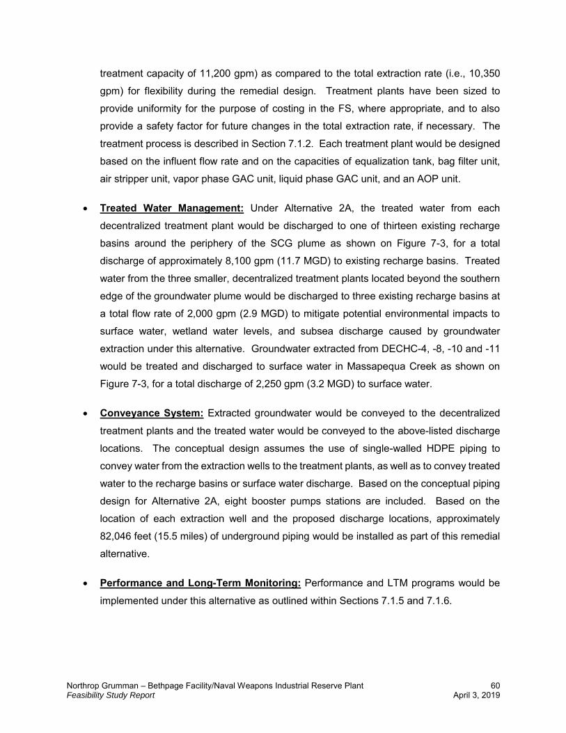
Northrop Grumman – Bethpage Facility/Naval Weapons Industrial Reserve Plant 60 Feasibility Study Report April 3, 2019
treatment capacity of 11,200 gpm) as compared to the total extraction rate (i.e., 10,350
gpm) for flexibility during the remedial design. Treatment plants have been sized to
provide uniformity for the purpose of costing in the FS, where appropriate, and to also
provide a safety factor for future changes in the total extraction rate, if necessary. The
treatment process is described in Section 7.1.2. Each treatment plant would be designed
based on the influent flow rate and on the capacities of equalization tank, bag filter unit,
air stripper unit, vapor phase GAC unit, liquid phase GAC unit, and an AOP unit.
Treated Water Management: Under Alternative 2A, the treated water from each
decentralized treatment plant would be discharged to one of thirteen existing recharge
basins around the periphery of the SCG plume as shown on Figure 7-3, for a total
discharge of approximately 8,100 gpm (11.7 MGD) to existing recharge basins. Treated
water from the three smaller, decentralized treatment plants located beyond the southern
edge of the groundwater plume would be discharged to three existing recharge basins at
a total flow rate of 2,000 gpm (2.9 MGD) to mitigate potential environmental impacts to
surface water, wetland water levels, and subsea discharge caused by groundwater
extraction under this alternative. Groundwater extracted from DECHC-4, -8, -10 and -11
would be treated and discharged to surface water in Massapequa Creek as shown on
Figure 7-3, for a total discharge of 2,250 gpm (3.2 MGD) to surface water.
Conveyance System: Extracted groundwater would be conveyed to the decentralized
treatment plants and the treated water would be conveyed to the above-listed discharge
locations. The conceptual design assumes the use of single-walled HDPE piping to
convey water from the extraction wells to the treatment plants, as well as to convey treated
water to the recharge basins or surface water discharge. Based on the conceptual piping
design for Alternative 2A, eight booster pumps stations are included. Based on the
location of each extraction well and the proposed discharge locations, approximately
82,046 feet (15.5 miles) of underground piping would be installed as part of this remedial
alternative.
Performance and Long-Term Monitoring: Performance and LTM programs would be
implemented under this alternative as outlined within Sections 7.1.5 and 7.1.6.

Northrop Grumman – Bethpage Facility/Naval Weapons Industrial Reserve Plant 61 Feasibility Study Report April 3, 2019
7.3.2 Alternative 2B – Hydraulic Containment of Site Contaminants above SCGs - Centralized Treatment Plants with a Centralized Recharge Basin
Alternative 2B includes the following components:
Groundwater Extraction: Alternative 2B includes the installation of 16 extraction wells,
which are shown on Figure 7-4. In total, these 16 extraction wells would remove
approximately 9,150 gpm (13.2 MGD) from the aquifer to provide capture of the SCG
plume. Extraction wells would be installed to depths ranging from approximately 300 feet
bgs to 950 feet bgs within the Magothy aquifer, with an estimated screen length of 100 to
200 feet per extraction well. The wells are designed to hydraulically contain contaminant
mass in shallow, intermediate, and deep zones. For the purpose of this FS, the proposed
number of extraction wells for each of the three depth zones are as follows:
o 7 Extraction wells in depth Zone 1 (down to 300 feet bgs);
o 4 Extraction wells in depth Zone 2 (from 300 feet bgs to 600 feet bgs); and
o 5 Extraction wells in depth Zone 3 (deeper than 600 feet bgs).
Ex-situ Treatment: Under Alternative 2B, contaminated groundwater from each
extraction well would be pumped, in general, to two centralized treatment plants as
described within Section 7.1.2. The north centralized treatment plant is proposed for
placement near the NGBF and NWIRP, and the south centralized treatment plant is
proposed for placement within state-owned property within the vicinity of Massapequa
Creek. Since the proposed location of the north treatment plant is in an area where land
would likely have to be acquired, an approximate cost for acquiring land for the north
treatment plant is included in the estimated costs for this alternative. Since the south
centralized treatment plant would be constructed within state-owned property under this
alternative, land acquisition for this plant is not included in the estimated cost.
Under this alternative, three decentralized treatment plants have also been proposed
within the southern-most reaches of the groundwater plume to facilitate return of water to
the aquifer system with existing recharge basins beyond the down-gradient edge of the
groundwater plume. Land for the construction of these treatment plants would likely have
to be acquired, and the cost for land acquisition of these treatment plants has been
included within the cost for this alternative. The approximate locations for the proposed
groundwater treatment plants are shown on Figure 7-4.
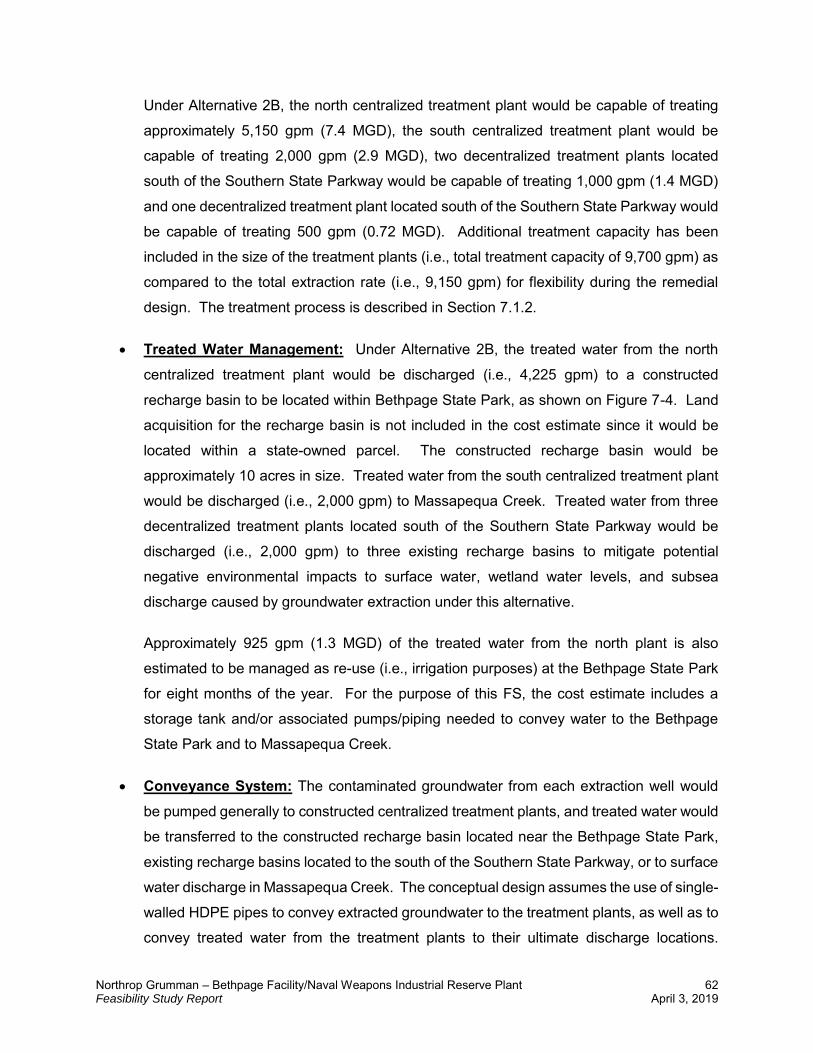
Northrop Grumman – Bethpage Facility/Naval Weapons Industrial Reserve Plant 62 Feasibility Study Report April 3, 2019
Under Alternative 2B, the north centralized treatment plant would be capable of treating
approximately 5,150 gpm (7.4 MGD), the south centralized treatment plant would be
capable of treating 2,000 gpm (2.9 MGD), two decentralized treatment plants located
south of the Southern State Parkway would be capable of treating 1,000 gpm (1.4 MGD)
and one decentralized treatment plant located south of the Southern State Parkway would
be capable of treating 500 gpm (0.72 MGD). Additional treatment capacity has been
included in the size of the treatment plants (i.e., total treatment capacity of 9,700 gpm) as
compared to the total extraction rate (i.e., 9,150 gpm) for flexibility during the remedial
design. The treatment process is described in Section 7.1.2.
Treated Water Management: Under Alternative 2B, the treated water from the north
centralized treatment plant would be discharged (i.e., 4,225 gpm) to a constructed
recharge basin to be located within Bethpage State Park, as shown on Figure 7-4. Land
acquisition for the recharge basin is not included in the cost estimate since it would be
located within a state-owned parcel. The constructed recharge basin would be
approximately 10 acres in size. Treated water from the south centralized treatment plant
would be discharged (i.e., 2,000 gpm) to Massapequa Creek. Treated water from three
decentralized treatment plants located south of the Southern State Parkway would be
discharged (i.e., 2,000 gpm) to three existing recharge basins to mitigate potential
negative environmental impacts to surface water, wetland water levels, and subsea
discharge caused by groundwater extraction under this alternative.
Approximately 925 gpm (1.3 MGD) of the treated water from the north plant is also
estimated to be managed as re-use (i.e., irrigation purposes) at the Bethpage State Park
for eight months of the year. For the purpose of this FS, the cost estimate includes a
storage tank and/or associated pumps/piping needed to convey water to the Bethpage
State Park and to Massapequa Creek.
Conveyance System: The contaminated groundwater from each extraction well would
be pumped generally to constructed centralized treatment plants, and treated water would
be transferred to the constructed recharge basin located near the Bethpage State Park,
existing recharge basins located to the south of the Southern State Parkway, or to surface
water discharge in Massapequa Creek. The conceptual design assumes the use of single-
walled HDPE pipes to convey extracted groundwater to the treatment plants, as well as to
convey treated water from the treatment plants to their ultimate discharge locations.
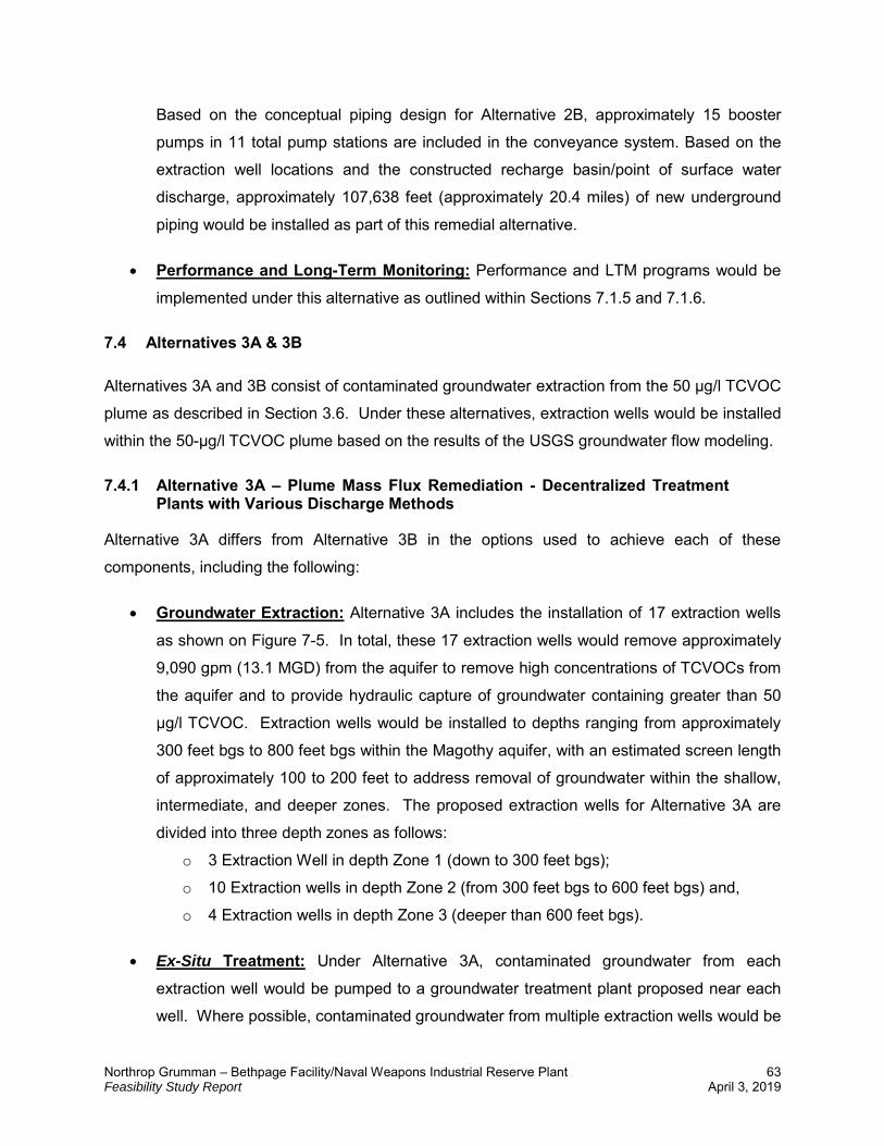
Northrop Grumman – Bethpage Facility/Naval Weapons Industrial Reserve Plant 63 Feasibility Study Report April 3, 2019
Based on the conceptual piping design for Alternative 2B, approximately 15 booster
pumps in 11 total pump stations are included in the conveyance system. Based on the
extraction well locations and the constructed recharge basin/point of surface water
discharge, approximately 107,638 feet (approximately 20.4 miles) of new underground
piping would be installed as part of this remedial alternative.
Performance and Long-Term Monitoring: Performance and LTM programs would be
implemented under this alternative as outlined within Sections 7.1.5 and 7.1.6.
7.4 Alternatives 3A & 3B
Alternatives 3A and 3B consist of contaminated groundwater extraction from the 50 µg/l TCVOC
plume as described in Section 3.6. Under these alternatives, extraction wells would be installed
within the 50-µg/l TCVOC plume based on the results of the USGS groundwater flow modeling.
7.4.1 Alternative 3A – Plume Mass Flux Remediation - Decentralized Treatment Plants with Various Discharge Methods
Alternative 3A differs from Alternative 3B in the options used to achieve each of these
components, including the following:
Groundwater Extraction: Alternative 3A includes the installation of 17 extraction wells
as shown on Figure 7-5. In total, these 17 extraction wells would remove approximately
9,090 gpm (13.1 MGD) from the aquifer to remove high concentrations of TCVOCs from
the aquifer and to provide hydraulic capture of groundwater containing greater than 50
µg/l TCVOC. Extraction wells would be installed to depths ranging from approximately
300 feet bgs to 800 feet bgs within the Magothy aquifer, with an estimated screen length
of approximately 100 to 200 feet to address removal of groundwater within the shallow,
intermediate, and deeper zones. The proposed extraction wells for Alternative 3A are
divided into three depth zones as follows:
o 3 Extraction Well in depth Zone 1 (down to 300 feet bgs);
o 10 Extraction wells in depth Zone 2 (from 300 feet bgs to 600 feet bgs) and,
o 4 Extraction wells in depth Zone 3 (deeper than 600 feet bgs).
Ex-Situ Treatment: Under Alternative 3A, contaminated groundwater from each
extraction well would be pumped to a groundwater treatment plant proposed near each
well. Where possible, contaminated groundwater from multiple extraction wells would be
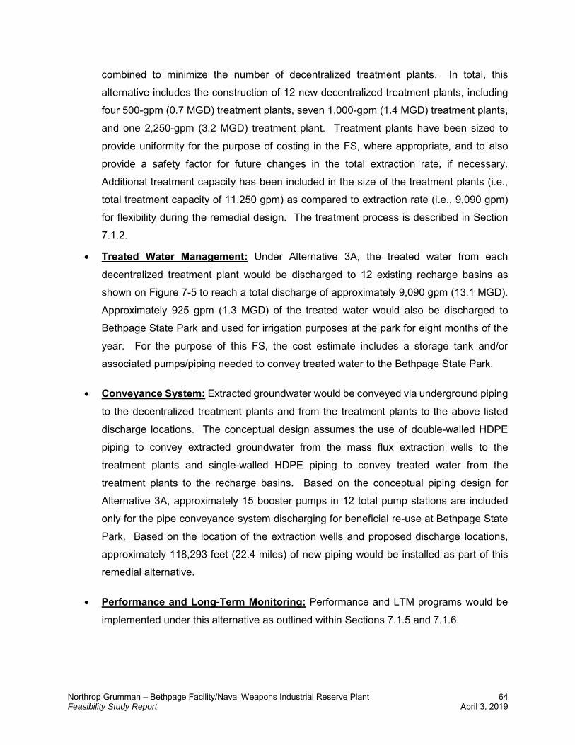
Northrop Grumman – Bethpage Facility/Naval Weapons Industrial Reserve Plant 64 Feasibility Study Report April 3, 2019
combined to minimize the number of decentralized treatment plants. In total, this
alternative includes the construction of 12 new decentralized treatment plants, including
four 500-gpm (0.7 MGD) treatment plants, seven 1,000-gpm (1.4 MGD) treatment plants,
and one 2,250-gpm (3.2 MGD) treatment plant. Treatment plants have been sized to
provide uniformity for the purpose of costing in the FS, where appropriate, and to also
provide a safety factor for future changes in the total extraction rate, if necessary.
Additional treatment capacity has been included in the size of the treatment plants (i.e.,
total treatment capacity of 11,250 gpm) as compared to extraction rate (i.e., 9,090 gpm)
for flexibility during the remedial design. The treatment process is described in Section
7.1.2.
Treated Water Management: Under Alternative 3A, the treated water from each
decentralized treatment plant would be discharged to 12 existing recharge basins as
shown on Figure 7-5 to reach a total discharge of approximately 9,090 gpm (13.1 MGD).
Approximately 925 gpm (1.3 MGD) of the treated water would also be discharged to
Bethpage State Park and used for irrigation purposes at the park for eight months of the
year. For the purpose of this FS, the cost estimate includes a storage tank and/or
associated pumps/piping needed to convey treated water to the Bethpage State Park.
Conveyance System: Extracted groundwater would be conveyed via underground piping
to the decentralized treatment plants and from the treatment plants to the above listed
discharge locations. The conceptual design assumes the use of double-walled HDPE
piping to convey extracted groundwater from the mass flux extraction wells to the
treatment plants and single-walled HDPE piping to convey treated water from the
treatment plants to the recharge basins. Based on the conceptual piping design for
Alternative 3A, approximately 15 booster pumps in 12 total pump stations are included
only for the pipe conveyance system discharging for beneficial re-use at Bethpage State
Park. Based on the location of the extraction wells and proposed discharge locations,
approximately 118,293 feet (22.4 miles) of new piping would be installed as part of this
remedial alternative.
Performance and Long-Term Monitoring: Performance and LTM programs would be
implemented under this alternative as outlined within Sections 7.1.5 and 7.1.6.
Northrop Grumman – Bethpage Facility/Naval Weapons Industrial Reserve Plant 65 Feasibility Study Report April 3, 2019
7.4.2 Alternative 3B – Plume Mass Flux Remediation - Centralized Treatment Plant with a Centralized Recharge Basin
Alternative 3B, differs from Alternative 3A in the options used to achieve each of these
components, including the following:
Groundwater Extraction: Alternative 3B includes the installation of 16 extraction wells
as shown on Figure 7-6. In total, these 16 extraction wells would remove approximately
7,140 gpm (10.3 MGD) from the aquifer to remove high concentrations of TCVOCs from
the aquifer and to provide hydraulic capture of groundwater containing greater than 50
µg/l TCVOCs. Extraction wells would be installed to depths ranging from approximately
300 feet bgs to 800 feet bgs within the Magothy aquifer, with an estimated screen length
of 100 to 200 feet. The proposed extraction wells for Alternative 3B are divided into three
depth zones as follows:
o 1 Extraction wells in depth Zone 1 (down to 300 feet bgs);
o 11 Extraction wells in depth Zone 2 (from 300 feet bgs to 600 feet bgs) and,
o 4 Extraction wells in depth Zone 3 (deeper than 600 feet bgs).
Ex-situ Treatment: Under Alternative 3B, the contaminated groundwater from each
extraction well would be pumped north to a centralized treatment plant with a capacity of
7,140 gpm (10.3 MGD) proposed within the vicinity of the NGBF and NWIRP. This
treatment plant is proposed for placement in an area where land would likely have to be
acquired. An approximate cost for acquiring land for the treatment plant is included in the
estimated costs for this alternative. The location of the proposed centralized treatment
plant under Alternative 3B is shown on Figure 7-6. The treatment process is described in
Section 7.1.2.
Treated Water Management: Under Alternative 3B, treated water from the centralized
treatment plant would be discharged (i.e., 6,215 gpm) to a constructed recharge basin to
be located within Bethpage State Park, as shown on Figure 7-6. Land acquisition for the
constructed recharge basin is not included in the cost estimate since it would be located
on state-owned property. The constructed recharge basin would be approximately 10
acres in size.
Approximately 925 gpm of the treated water is also assumed to be discharged for re-use
(i.e., irrigation purposes) at Bethpage State Park for eight months of the year. For the
Northrop Grumman – Bethpage Facility/Naval Weapons Industrial Reserve Plant 66 Feasibility Study Report April 3, 2019
purpose of this FS, the cost estimate includes a storage tank and the associated
pumps/piping needed to provide treated water to the Bethpage State Park.
Conveyance System: The contaminated groundwater from each extraction well would
be pumped to a centralized treatment plant, and treated water would be pumped to the
constructed recharge basin located within Bethpage State Park. The conceptual design
assumes the use of double-walled HDPE piping to convey groundwater from the mass
flux extraction well to the centralized treatment plant and single-walled HDPE piping to
convey treated water from treatment plant to the recharge basin. Based on the conceptual
piping design for Alternative 3B, approximately 13 booster pumps in 10 pump stations are
included in the conveyance system. Based on the proposed location of the extraction
wells and new recharge basin, approximately 82,457 feet (15.6 miles) of new piping would
be installed under this remedial alternative.
Performance and Long-Term Monitoring: Performance and LTM programs would be
implemented under this alternative as outlined within Sections 7.1.5 and 7.1.6.
7.5 Alternative 4 – Aquifer Flushing
Alternative 4, identified as Aquifer Flushing, involves the extraction of contaminated groundwater
from the 100 µg/l TCVOC plume as described in Section 3.6, ex-situ treatment using multiple
decentralized treatment plants, conveyance via piping, injection of treated water into the
subsurface, and performance monitoring. Under this alternative, extraction wells would be
installed within the 100-µg/l plume at locations based on the results of the groundwater flow
modeling. Once treated, the water would be injected into the aquifer to increase the movement
of groundwater toward the extraction wells, enhance hydraulic control of the aquifer, and prevent
further contaminant migration. This aquifer flushing approach is included to expedite remediation
of impacted groundwater. The timeframe for remediation of the 100 µg/l plume under this
alternative has been estimated to be 17 years; however, this alternative would not achieve the
RAOs since this alternative only addresses portions of the plume with COCs greater than 100
µg/l.
Major components of Alternative 4 include the following:
Groundwater Extraction: Alternative 4 includes the installation of 23 extraction wells,
with an estimated extraction rate ranging from 50 gpm to 1,000 gpm per well totaling 8,670
Northrop Grumman – Bethpage Facility/Naval Weapons Industrial Reserve Plant 67 Feasibility Study Report April 3, 2019
gpm (12.5 MGD). The extraction well locations are shown on Figure 7-7. Extraction wells
would be installed to depths ranging from approximately 300 feet bgs to 1,000 feet bgs
within the Magothy aquifer, with an estimated screen length of 100 to 300 feet for removal
of contaminated groundwater within the shallow, intermediate, and deep zones. The
proposed extraction wells for Alternative 4 are divided into three depth zones as follows:
o 5 Extraction wells in depth Zone 1 (down to 300 feet bgs);
o 11 Extraction wells in depth Zone 2 (from 300 feet bgs to 600 feet bgs) and,
o 7 Extraction wells in depth Zone 3 (deeper than 600 feet bgs).
Ex-Situ Treatment: Under Alternative 4, the contaminated groundwater from each
extraction well would be pumped to a decentralized groundwater treatment plant
constructed within the vicinity of each extraction well. In total, this alternative includes
construction and operation of three 100-gpm (0.1 MGD) treatment plants, five 200-gpm
(0.3 MGD) treatment plants, five 300-gpm (0.4 MGD) treatment plants, seven 500-gpm
(0.7 MGD), and three 1,000-gpm (1.4 MGD) treatment plants. Additional treatment
capacity has been included in the size of the treatment plants (i.e., total treatment capacity
of 9,300 gpm) as compared to the total extraction rate (i.e., 8,670 gpm) for flexibility during
the remedial design.
The treatment process is described in Section 7.1.2 in detail.
Treated Water Management: Under Alternative 4, the treated water from each
decentralized treatment plant would be returned to the Magothy aquifer via 43 injection
wells (Figure 7-7). Groundwater recharge (i.e., 8,670 gpm) by injection is used under this
alternative to enhance hydraulic control and flushing of contamination zones. The
injection rate for each of the injection wells ranges from 25 gpm (0.04 MGD) to 700 gpm
(1 MGD). Well locations are based on the USGS groundwater flow modeling and particle
tracking analysis.
Injection wells would be installed to depths ranging from approximately 160 feet bgs to
900 bgs. The proposed injection wells for Alternative 4 are divided into three depth zones
as follows:
o 8 Injection wells in depth Zone 1 (depth to 300 feet bgs);
o 20 Injection wells in depth Zone 2 (from 300 feet bgs to 600 feet bgs) and,
o 15 Injection wells in depth Zone 3 (deeper than 600 feet bgs).
Northrop Grumman – Bethpage Facility/Naval Weapons Industrial Reserve Plant 68 Feasibility Study Report April 3, 2019
Conveyance System: Under this alternative, underground piping would be used to
convey extracted groundwater to the decentralized treatment plant and then from the
treatment plant to the injection wells. The conceptual design assumes the use of single-
walled HDPE piping to convey extracted groundwater the short distance from the
extraction well to the treatment plant, single-walled HDPE piping is also used to convey
treated water to the injection wells. Based on the anticipated requirement of 23 extraction
wells and 43 injection wells, two booster pumps in one pump station and approximately
93,282 feet (17.7 miles) of underground piping would be installed under this alternative.
Performance and Long-Term Monitoring: Performance and LTM programs would be
implemented under this alternative as outlined within Sections 7.1.5 and 7.1.6.
7.6 Alternatives 5A & 5B
Alternatives 5A and 5B represent, in general, a combination of Alternative 2 (Hydraulic
Containment of Site Contaminants above SCGs) and Alternative 3 (Plume Mass Flux
Remediation). Under these alternatives, extraction wells would be installed within the 50-µg/l
plume as described in Section 3.6, as well as along the western edge and southern edge of the
SCG plume. The extraction well locations are based on USGS groundwater flow modeling and
particle tracking analysis. The extraction wells installed within the 50-µg/l plume are designed to
expedite cleanup of areas where high concentrations of site contaminants exist while extraction
wells installed along the margins of the SCG plume are designed to prevent continued expansion
of the groundwater plume. The pumping rates for the extraction wells under these alternatives are
estimated to range from 150 gpm to 1,000 gpm depending upon their location within the
groundwater plume.
7.6.1 Alternative 5A – Hydraulic Containment of Site Contaminants above SCGs Combined with Mass Flux Remediation - Decentralized Treatment Plants with Various Discharge Methods
Alternative 5A differs from Alternative 5B in the options used to achieve each of these components
as described below:
Groundwater Extraction: Alternative 5A includes the installation of 8 extraction wells for
the purpose of mass flux remediation within the 50-µg/l plume and 16 wells for hydraulic
containment of the SCG plume as shown on Figure 7-8. The total rate of groundwater
extraction under this alternative is estimated to be 13,340 gpm (19.2 MGD). The location
Northrop Grumman – Bethpage Facility/Naval Weapons Industrial Reserve Plant 69 Feasibility Study Report April 3, 2019
and estimated extraction rate for each of the extraction wells were determined based on
the groundwater modeling performed by the USGS. Extraction wells would be installed to
depths ranging from approximately 300 feet bgs to 950 feet bgs, with an average screen
length of 100 to 200 feet to remove contaminant mass from shallow, intermediate, and
deep zones in the Magothy aquifer. Specifically, the proposed extraction wells for
Alternative 5A are divided into three depth zones as follows:
o 8 Extraction Wells in depth Zone 1 (down to 300 feet bgs);
o 10 Extraction Wells in depth Zone 2 (from 300 feet bgs to 600 feet bgs) and;
o 6 Extraction Wells in depth Zone 3 (deeper than 600 feet bgs).
Ex-Situ Treatment: Under Alternative 5A, contaminated groundwater from each
extraction well would be pumped to decentralized groundwater treatment plants to be
constructed within the vicinity of each of the wells. Where possible, the flow from multiple
wells would be combined for treatment in a single plant. In total, this alternative includes
the construction of 17 decentralized treatment plants. One treatment plant is designed for
an influent flow rate of approximately 1,250 gpm (1.8 MGD), four treatment plants are
designed for an influent flow rate of approximately 500 gpm (0.72 MGD), 11 treatment
plants are designed for an influent flow rate of approximately 1,000 gpm (1.4 MGD), and
one plant (along the Southern State Parkway near Massapequa Creek) is designed for a
treatment rate of approximately 1,500 gpm (2.2 MGD). Additional treatment capacity has
been included in the size of the treatment plants (i.e., total treatment capacity of 15,750
gpm) as compared to extraction rate (i.e., 13,340 gpm) for flexibility during the remedial
design. The treatment process is described in more detail within Section 7.1.2.
Treated Water Management: Under Alternative 5A, the treated water from each
decentralized treatment plant would be discharged to one of sixteen existing recharge
basins around the periphery of the plume as shown on Figure 7-8, for a total discharge of
approximately 10,915 gpm (15.7 MGD) to existing recharge basins. Approximately 2,000
gpm would be discharged to three recharge basins south of the Southern State Parkway
to mitigate potential environmental impacts to surface water, wetland water levels, and
subsea discharge caused by groundwater extraction under this alternative. Groundwater
extracted from DECHC -8, -10 and -11 would be treated and discharged to surface water
in Massapequa Creek as shown on Figure 7-8, for a total discharge of 1,500 gpm (2.2
MGD) to surface water.
Northrop Grumman – Bethpage Facility/Naval Weapons Industrial Reserve Plant 70 Feasibility Study Report April 3, 2019
Approximately 925 gpm of the treated water is also assumed to be discharged for re-use
(i.e., irrigation purposes) at Bethpage State Park for eight months of the year. For the
purpose of this FS, the cost estimate includes a storage tank and the associated
pumps/piping needed to provide treated water to the Bethpage State Park.
Conveyance System: Extracted groundwater would be conveyed via underground pipe
to the decentralized treatment plant, and from the treatment plant to the above-listed
discharge locations. The conceptual design assumes the use of double-walled HDPE
piping to convey groundwater from each mass flux extraction well to the treatment plant;
single-walled HDPE piping is used to convey groundwater from hydraulic control
extraction wells to the treatment plant, as well as treated water from the treatment plant to
the recharge basins, surface water, and/or irrigation system. Based on the conceptual
piping design for Alternative 5A, 13 booster pumps in 12 pump stations are necessary for
conveying water to Bethpage State Park and to Massapequa Creek. Based on the
extraction well and discharge locations, approximately 131,063 feet (24.8 miles) of
underground conveyance piping would be installed as part of Alternative 5A.
Performance and Long-Term Monitoring: Performance and LTM programs would be
implemented under this alternative as outlined within Sections 7.1.5 and 7.1.6.
7.6.2 Alternative 5B – Hydraulic Containment of Site Contaminants above SCGs Combined with Mass Flux Remediation - Centralized Treatment Plants with a Centralized Recharge Basin
Alternative 5B, differs from Alternative 5A in the options used to achieve each of these
components, as described below:
Groundwater Extraction: Alternative 5B also includes the installation of 8 extraction wells
for the purpose of mass flux remediation within the 50-µg/l plume, and the installation of
16 wells for hydraulic containment of the SCG plume as shown on Figure 7-9. The total
rate of groundwater extraction under this alternative is estimated to be 12,140 gpm (17.5
MGD). The location and estimated extraction rate for each of the extraction wells were
determined based on USGS groundwater modeling. Extraction wells would be installed
to depths ranging from 300 feet bgs to 950 feet bgs within the Magothy aquifer, with an
estimated screen length of 100 to 200 feet to address removal of contaminant mass in
shallow, intermediate, and deep zones and to capture COCs above SCGs. The proposed
extraction wells for Alternative 5B are divided into three depth zones as follows:
Northrop Grumman – Bethpage Facility/Naval Weapons Industrial Reserve Plant 71 Feasibility Study Report April 3, 2019
o 8 Extraction Wells in depth Zone 1 (down to 300 feet bgs);
o 10 Extraction Wells in depth Zone 2 (from 300 feet bgs to 600 feet bgs) and;
o 6 Extraction Wells in depth Zone 3 (deeper than 600 feet bgs).
Ex-situ Treatment: Under Alternative 5B, contaminated groundwater from each
extraction well would be pumped to one of two centralized treatment plants as described
within Section 7.1.2. The north centralized treatment plant is proposed for placement in
the vicinity of the former Northrop Grumman property, and the south centralized treatment
plant is proposed for placement within state-owned property near Massapequa Creek.
The north treatment plant is proposed for placement in an area where land would likely
have to be acquired. An approximate cost for acquiring land for the north treatment plant
is therefore included in the estimated costs for this alternative. Since the south centralized
treatment plant is assumed to be constructed within state owned property, land acquisition
for this plant is not included in the estimated cost.
Under this alternative, three decentralized treatment plants have been proposed within the
southern-most reaches of the groundwater plume to facilitate the return of water to the
aquifer system with existing recharge basins beyond the down-gradient edge of the
groundwater plume. Land for the construction of these treatment plants would likely have
to be acquired, and the cost for land acquisition of these treatment plants has been
included within the cost for this alternative. The approximate locations for the proposed
groundwater treatment plants are shown on Figure 7-9.
Under Alternative 5B, the north centralized treatment plant would be capable of treating
approximately 8,140 gpm (11.7 MGD), the south treatment plant for discharge to
Massapequa Creek would be capable of treating 2,000 gpm (2.8 MGD), two decentralized
treatment plants located south of the Southern State Parkway would be capable of treating
1,000 gpm (1.4 MGD) each and one decentralized treatment plant located south of the
Southern State Parkway would be capable of treating 500 gpm (0.72 MGD). Additional
treatment capacity has been included in the size of the treatment plants (i.e., total
treatment capacity of 12,640 gpm) as compared to extraction rate (i.e., 12,140 gpm) for
flexibility during the remedial design. The treatment process is described in Section 7.1.2.
Treated Water Management: Under Alternative 5B, the treated water from the north
centralized treatment plant would be discharged to a constructed recharge basin located
Northrop Grumman – Bethpage Facility/Naval Weapons Industrial Reserve Plant 72 Feasibility Study Report April 3, 2019
within Bethpage State Park (Figure 7-9). Land acquisition costs for the constructed
recharge basin are not included in the cost estimate since it would be located within state-
owned property. The footprint of the constructed recharge basin would be approximately
10 acres based on an anticipated flow rate of 7,215 gpm (10.4 MGD). Approximately 10%
(925 MGD) of the treated water is also assumed to be discharged for re-use (i.e., irrigation
purposes) at Bethpage State Park for eight months a year. For the purpose of this FS, a
storage tank and required pumps/piping needed to convey water to Bethpage State Park
is included in cost estimates.
Treated water from the south centralized treatment plant would be discharged to
Massapequa Creek at a flow rate of approximately 2,000 gpm (2.9 MGD). Treated water
from the three smaller, decentralized treatment plants located beyond the southern edge
of the groundwater plume would be discharged to three existing recharge basins at a total
flow rate of 2,000 gpm (2.9 MGD) to mitigate potential environmental impacts to surface
water, wetland water levels, and subsea discharge caused by groundwater extraction
under this alternative.
Conveyance System: Impacted groundwater from each extraction well would be pumped
via underground piping to one of several constructed treatment plants, and treated water
would be pumped to a constructed recharge basin located within Bethpage State Park, an
irrigation storage tank for the park, to surface water within Massapequa Creek, or three
existing recharge basins located to the south of the groundwater plume. The conceptual
design assumes the use of double-walled HDPE underground piping to convey
groundwater from each mass flux extraction well to the treatment plants; single-walled
HDPE piping is used to convey groundwater from hydraulic control extraction wells to the
treatment plants, as well as treated water from the treatment plants to the recharge basins
and Massapequa Creek. Based on the conceptual piping design for Alternative 5B,
approximately 17 booster pumps in 13 stations are included in the conveyance system
based on a pump station for every 5,000 linear feet of piping. Based on the location of
the extraction wells and discharge locations, approximately 124,411 feet (23.6 miles) of
new piping would be constructed as part of this remedial alternative.
Performance and Long-Term Monitoring: Performance and LTM programs would be
implemented under this alternative as outlined within Sections 7.1.5 and 7.1.6.
Northrop Grumman – Bethpage Facility/Naval Weapons Industrial Reserve Plant 73 Feasibility Study Report April 3, 2019
8 DETAILED EVALUATION OF ALTERNATIVES
This section presents a detailed evaluation of the remedial alternatives described in Section 7.2
relative to the eight evaluation criteria summarized below. The purpose of the evaluation is to
identify the advantages and disadvantages of each alternative.
8.1 Evaluation Criteria
The evaluation was based on criteria established under NYSDEC DER-10: Technical Guidance
for Site Investigation and Remediation, Section 4.2. The evaluation criteria are as follows:
Overall protection of human health and the environment: This criterion is an
evaluation of the alternative’s ability to protect public health and the environment,
assessing how risks posed through each existing or potential pathway of exposure are
eliminated, reduced, or controlled through removal, treatment, engineering controls, or
ICs. The alternative’s ability to achieve each of the RAOs is evaluated.
Compliance with Standards, Criteria, and Guidance: This criterion evaluates the
compliance of the alternative with all identified SCGs and evaluates whether or not the
remedy will achieve compliance.
Long-term effectiveness and permanence: Each alternative is evaluated for its long-
term effectiveness after implementation. If wastes or treated residuals remain after the
selected remedy has been implemented, the following items are evaluated:
o The magnitude of the remaining risks (i.e., whether there will be any significant
threats, exposure pathways, or risks to the community and environment from the
remaining wastes or treated residuals);
o The adequacy of the engineering and ICs intended to limit the risk;
o The reliability of these controls; and
o The ability of the remedy to continue to meet RAOs in the future.
Reduction of toxicity, mobility, or volume of contamination through treatment: Each
alternative’s ability to reduce the toxicity, mobility, or volume of COCs is evaluated.
Preference is given to remedies that permanently and significantly reduce the toxicity,
mobility, or volume of the wastes at the site.
Short-term impacts and effectiveness: The potential short-term adverse impacts and
risks of the remedy upon the community, the workers, and the environment during
construction, and/or implementation are evaluated. A discussion is presented as to how
Northrop Grumman – Bethpage Facility/Naval Weapons Industrial Reserve Plant 74 Feasibility Study Report April 3, 2019
the identified potential adverse impacts to the community or workers at the site will be
controlled, as well as the effectiveness of those controls. A discussion of engineering
controls that will be used to mitigate short-term impacts (e.g., dust control measures) is
provided. The length of time needed to achieve the remedial objectives is also estimated.
Implementability: The technical and administrative feasibility of implementing each
alternative is evaluated for this criterion. Technical feasibility includes the difficulties
associated with construction and the ability to monitor the effectiveness of the remedy.
For administrative feasibility, the availability of the necessary personnel and material is
evaluated along with potential difficulties in obtaining specific operating approvals, access
for construction, etc.
Cost Effectiveness: This criterion is an evaluation of the overall cost effectiveness of an
alternative or remedy. This criterion evaluates the estimated capital, operations,
maintenance, and monitoring costs. Costs are estimated and presented on a present-
worth basis. The present worth costs were estimated with expected accuracies of -30 to
+50 percent in accordance with NYSDEC and USEPA guidance. Because detailed
remedial design activities have not been performed, a contingency has been included
within the cost for each alternative to account for potential changes in scope (and costs)
that may be identified during the design and implementation activities. In accordance with
USEPA and NYSDEC guidance, a 3 percent discount rate (before taxes and after inflation)
was used to calculate present worth.
Land Use: This criterion evaluates the current, intended, and reasonably anticipated
future use of the site and its surroundings, as it relates to an alternative or remedy when
unrestricted levels are not achieved.
The eight groundwater alternatives that were identified and pre-screened for detailed evaluation
include:
Alternative 1 – No Further Action (existing & planned remedial systems);
Alternative 2A – Hydraulic Containment of Site Contaminants above SCGs - Decentralized
Treatment Plants with Various Discharge Methods;
Alternative 2B – Hydraulic Containment of Site Contaminants above SCGs - Centralized
Treatment Plants with a Centralized Recharge Basin;
Alternative 3A – Plume Mass Flux Remediation - Decentralized Treatment Plants with
Various Discharge Methods;
Northrop Grumman – Bethpage Facility/Naval Weapons Industrial Reserve Plant 75 Feasibility Study Report April 3, 2019
Alternative 3B – Plume Mass Flux Remediation - Centralized Treatment Plant with a
Centralized Recharge Basin;
Alternative 4 – Aquifer Flushing;
Alternative 5A – Hydraulic Containment of Site Contaminants above SCGs Combined with
Mass Flux Remediation - Decentralized Treatment Plants with Various Discharge
Methods; and
Alternative 5B – Hydraulic Containment of Site Contaminants Above SCGs Combined with
Mass Flux Remediation - Centralized Treatment Plants with a Centralized Recharge
Basin.
An individual analysis of the groundwater alternatives against the criteria was conducted and is
presented below. A summary of the evaluation is provided in Table 8-1. Cost breakdowns for
each alternative are presented within Appendix A and summarized in Table 8-2.
8.2 Alternative 1 – No Further Action
The No Further Action option is included as a basis for comparison with active groundwater
remediation technologies in accordance with Section 4.2 of DER-10. At this site, the no further
action alternative assumes that no additional remedial actions would be taken beyond what has
already been implemented or planned in regard to the on-site and off-site groundwater
contamination. On-going remedial efforts being conducted by the Navy and Northrop Grumman
are described in Section 3, but generally include:
Operation of the On-Site Groundwater Containment System (5 remediation wells);
Operation of the Bethpage Community Park Groundwater Containment System (4
remediation wells);
Operation of the GM-38 Groundwater Extraction and Treatment System (1-2 remediation
wells;
Future operation of the RW-21 Area Groundwater Extraction and Treatment System (3 or
more remediation wells);
Future operation of the RE-108 Groundwater Extraction and Treatment System (3 or more
remediation wells);
Implementation of the PWS Contingency Plan and continued wellhead treatment at six
public water supplies.
Northrop Grumman – Bethpage Facility/Naval Weapons Industrial Reserve Plant 76 Feasibility Study Report April 3, 2019
If no further active remedial action is taken, contaminants already present in the groundwater
would persist and RAOs for the site would not be met. While there would be reductions in
contaminant concentrations near the future groundwater extraction and treatment systems (RW-
21 Area and RE-108 Area), there would not be a significant reduction in contaminant
concentrations outside of the influence of these two systems. This would allow contaminants to
continue to move in a southward direction towards public water supply wells and environmental
receptors.
8.2.1 Overall protection of human health and the environment
Alternative 1 provides no further control of exposure to contaminated groundwater and no further
reduction in risk to the environment posed by contaminated groundwater. The No Further Action
alternative does not attain the groundwater RAOs (e.g., restoration of the resource) and does not
enhance the protection of human health. The alternative allows for the continued, uncontrolled
migration of the groundwater contamination that has already impacted public water supplies. This
alternative could result in impacts to wetlands, stream flow, and subsea discharge and to
additional public water supply wells.
8.2.2 Compliance with SCGs
Alternative 1 does not comply with SCGs. Contaminated groundwater would continue to exhibit
concentrations above the SCGs and it would continue to migrate in the down-gradient direction
towards receptors. This continued migration would result in a larger volume of the aquifer
containing groundwater with COCs present at concentrations exceeding SCGs.
8.2.3 Long-term effectiveness and permanence
Alternative 1 does not provide long-term effectiveness or permanence. Groundwater containing
COCs from a concentration less than approximately 1,000 µg/l to the SCGs would continue to
migrate. If no further active remedial action is taken, contaminants in the groundwater would
continue to migrate towards receptors and RAOs for the site would not be met in the long term.
8.2.4 Reduction of toxicity, mobility, or volume of contamination through treatment
Alternative 1 would not provide a reduction in toxicity, mobility, or volume for COCs that occur at
a concentration less than approximately 1,000 µg/l to the SCGs and these COCs would continue
to migrate toward public water supplies, wetlands, stream flow, and subsea discharge.
Northrop Grumman – Bethpage Facility/Naval Weapons Industrial Reserve Plant 77 Feasibility Study Report April 3, 2019
8.2.5 Short-term impacts and effectiveness
This alternative does not result in disruption of properties overlying the plume, and therefore no
additional short-term risks are posed to the community, workers, or the environment, as no
additional remedial action would occur (beyond those activities associated with the existing and
proposed groundwater extraction and treatment systems).
8.2.6 Implementability
There are no implementability concerns posed by this remedy, as no additional remedial actions
are being implemented.
8.2.7 Cost Effectiveness
Because this is a No Further Action alternative, the capital, O&M, and net present worth costs are
estimated to be $0.
8.2.8 Land Use
The No Further Action alternative would result in groundwater contaminants in excess of SCGs
remaining in the aquifer beneath the off-site properties. No environmental easements would be
put in place. This alternative would not affect the current, intended, or reasonably anticipated
future use of the area, which is a mix of residential, commercial/industrial, and recreational use.
8.3 Alternative 2A – Hydraulic Containment of Site Contaminants above SCGs - Decentralized Plants with Various Discharge Methods
Alternative 2A includes extraction of contaminated groundwater from the aquifer within the area
where COC concentrations exceed the SCGs through the installation of 16 groundwater
extraction wells installed to depths ranging from 300 to 950 feet within the Magothy aquifer, ex-
situ treatment using multiple decentralized treatment plants, conveyance via underground piping,
treated water management, and performance monitoring. This alternative also includes LTM for
protection of human health and the environment. Under this alternative, it is assumed that a Pre-
Design Investigation (PDI), treatability/bench studies, and an engineering evaluation would be
completed.
The period of performance of this alternative could be as long as 130 years based on the
assumptions listed in Section 7.1.7 and the extraction rate of 14.9 MGD. For the purpose of
Northrop Grumman – Bethpage Facility/Naval Weapons Industrial Reserve Plant 78 Feasibility Study Report April 3, 2019
calculating the present worth cost for this FS, it is assumed that this alternative would be active
for 30 years.
8.3.1 Overall protection of human health and the environment
Alternative 2A would protect human health and the environment by hydraulically containing
groundwater with COCs above the SCGs with a series of wells along the western and southern
edges of the SCG plume. The groundwater would be treated in 13 decentralized treatment plants
to the NYS groundwater effluent limitations before it is returned to the aquifer through 13 recharge
basins. It is expected that the hydraulic containment of groundwater containing COCs exceeding
the SCGs and the treatment and recharge of groundwater meeting NYS groundwater effluent
limitations would allow unrestricted use of the groundwater resources. With the withdrawal of
contaminated groundwater from 16 extraction wells, it is expected that Alternative 2A would
reduce impacts to public water supply wells that currently contain site contaminants in raw
groundwater and this alternative would prevent impacts to currently un-impacted water supply
wells. LTM would be used to monitor remediation progress throughout the operational years of
the extraction and treatment system.
The groundwater flow model constructed by the USGS was used to evaluate the potential
environmental effects (e.g., on surface water flow, water levels in wetlands, water levels in public
water supply wells, and subsea discharge) associated with the implementation of Alternative 2A.
Through an iterative modeling process, the numbers, locations, and pumping rates of extraction
wells and the locations of recharge basins were adjusted to achieve hydraulic capture of the SCG
plume while at the same time minimizing the potential effects to the environment. Based on this
evaluation and compared to the No Further Action Alternative, it is expected that Alternative 2A
would not have an effect on the environment. The specific potential changes to surface water
flow, water levels in wetlands, water levels in public water supply wells, and subsea discharge for
Alternative 2A are summarized in Table 8-3.
The groundwater flow model predicts (Table 8-3) that in nine of 13 public water supply wells, the
water level will decrease from 0.3 to 2.0 feet; and in the remaining four public water supply wells,
groundwater levels will decrease from 4.0 to 4.6 feet. These potential changes to the water level
are not expected to affect the yield of the wells, given the well depths, specific capacity, and well
efficiency of these public water supply wells.
Northrop Grumman – Bethpage Facility/Naval Weapons Industrial Reserve Plant 79 Feasibility Study Report April 3, 2019
The groundwater flow modeling for Alternative 2A predicts the stream flow in Massapequa Creek
will increase 3.4 cfs. This increase in stream flow is likely to be a benefit to the local aquatic
habitat. The stream flow in Seaford Creek, Seamans Creek, and Bellmore Creek will decrease
from zero to 0.4 cfs. This small decrease in stream flow is not expected to adversely affect the
aquatic habitat.
The groundwater flow modeling predicts the water table elevation in wetlands south of the site
will increase from zero to 1.6 feet, while others will decrease from zero to 0.5 feet during
implementation of Alternative 2A. According to the National Wetlands Inventory, the wetlands
have been classified as Freshwater Forested/Shrub Wetlands. These wetlands are flooded or
ponded for 14 or more consecutive days during the growing season from precipitation runoff. The
depth to the water table typically lies well below the ground surface for most of the year. The
saturated conditions during the growing season is from heavy precipitation/runoff and not
controlled by the depth to the water table (National Research Council 1995). Therefore, no
adverse impacts to the wetland environments are anticipated as a result of a small change in the
water table.
The potential effect to the position of the saltwater-freshwater interface was evaluated by
modeling the potential changes in subsea discharge. Groundwater flow modeling predicts
groundwater flow through the GHB into the Magothy aquifer will not change, while the
groundwater flow through the GHB out of the Magothy aquifer will increase by 0.4% (2 gpm).
Groundwater flow modeling also predicts groundwater flow through the GHB into the Lloyd will
increase by 5.6% (6 gpm), while the groundwater flow through the GHB out of the Lloyd will remain
at zero. These small changes in boundary conditions are not expected to affect the position of
the saltwater interface under Alternative 2A.
It is not expected that the overall safe yield of the aquifer would be affected by implementation of
Alternative 2A since a large fraction of the groundwater extracted from the aquifer would be
returned to the aquifer through recharge basins.
8.3.2 Compliance with SCGs
Alternative 2A will reduce the concentration of COCs in groundwater to below the SCGs since
groundwater with COCs above SCGs will be hydraulically contained and treated. Treated water
would meet the New York State groundwater effluent limitations prior to being discharged to
Northrop Grumman – Bethpage Facility/Naval Weapons Industrial Reserve Plant 80 Feasibility Study Report April 3, 2019
existing recharge basins and/or to surface water at Massapequa Creek. Alternative 2A would
continue until COCs are below the SCGs.
8.3.3 Long-term effectiveness and permanence
Groundwater extraction and treatment systems have been demonstrated to be effective and
reliable at numerous sites for groundwater treatment for VOCs. Alternative 2A would provide
long-term effectiveness by hydraulically containing (extracting) groundwater containing COCs at
concentrations above the SCGs. VOCs would be permanently removed from groundwater with
air stripping and GAC processes. 1,4-Dioxane would be permanently removed from groundwater
with AOP. A LTM program would be implemented to verify the long-term effectiveness of the
extraction and treatment system and to assess the remedy’s ability to protect human health and
the environment.
Alternative 2A would allow unrestricted use of groundwater resources outside of the SCG plume.
The concentration of site-related COCs in groundwater extracted by public water supply wells is
expected to decrease during operation of the remedy. With hydraulic control of the SCG plume,
Alternative 2A is expected to prevent currently un-impacted public water supply wells from
requiring treatment to address the COCs.
8.3.4 Reduction of toxicity, mobility, or volume of contamination through treatment
Alternative 2A would reduce the toxicity, mobility, and volume of COCs in the aquifer through
groundwater extraction and treatment at the down-gradient edge of the SCG plume. Alternative
2A would reduce the toxicity and mobility of COCs by hydraulically containing groundwater with
COCs at concentrations exceeding the SCGs. Once the contaminated groundwater is withdrawn
from the aquifer, the water is treated at the surface via an air stripping and carbon treatment
process to address VOCs, as well as AOP to specifically address 1,4-dioxane. Contaminants
trapped on the GAC adsorption media would be destroyed during regeneration or disposed in
accordance with applicable waste regulations. AOP provides complete destruction and
mineralization of many chlorinated solvents, including 1,4-dioxane. The volume of contaminated
groundwater within the SCG plume used in Alternative 2A has been estimated to be
approximately 150 billion gallons. The volume of the SCG plume would be reduced in Alternative
2A by extracting 14.9 MGD over an estimated 130 years.
Northrop Grumman – Bethpage Facility/Naval Weapons Industrial Reserve Plant 81 Feasibility Study Report April 3, 2019
8.3.5 Short-term impacts and effectiveness
Groundwater extraction systems are effective at controlling the migration of groundwater
containing COCs above the SCGs and removing contaminant mass from an aquifer over the
short-term. Groundwater extraction systems would induce a hydraulic gradient, capturing COCs
within days or weeks of system startup. Extraction of contaminated groundwater to the surface
for treatment increases the risks of contaminant exposure to workers, the community, and the
environment. However, safety techniques, including community air monitoring, traffic control
plans, and street closure permits would be implemented during construction. In addition, alarmed
monitoring equipment would be used to minimize risks from failures of treatment system
components. A fence and other potential security measures would be installed around the
treatment system facilities to restrict access, discourage trespassers, and limit potential exposure.
Short-term impacts would be incurred during the construction of:
16 extraction wells for hydraulic containment;
13 treatment plants;
13 existing recharge basins to be reworked; and
82,046 feet (15.5 miles) of conveyance piping.
The most significant disruption to traffic would be caused during construction of 82,046 feet (15.5
miles) of conveyance piping under Alternative 2A. Pipe crossings at the Southern State Parkway
and the Seaford-Oyster Bay Expressway may also represent difficult challenges. Increased traffic
and noise during well installation, underground piping installation, and treatment system
construction is expected; however, noise and traffic control plans outlining standard work
practices and engineering controls would be implemented to reduce impacts to the community to
the extent possible. The construction of this alternative has been estimated to take up to five
years. Contaminated water produced during well construction, operations, and LTM would be
appropriately managed according to Federal, State, and local regulations.
8.3.6 Implementability
Groundwater extraction and treatment is implementable as the technique uses well-established
technologies and the equipment and services needed to install and operate the treatment system
and to sample groundwater monitoring wells are commercially available. PDI, pilot testing, and
property evaluation would be necessary to determine optimal well placement, flow rates, and any
Northrop Grumman – Bethpage Facility/Naval Weapons Industrial Reserve Plant 82 Feasibility Study Report April 3, 2019
required pre-treatment. The treatment components can be expanded to improve treatment
effectiveness or handle increased flow rates, if required.
Acquiring the land and the construction of the extraction wells, treatment facilities, and recharge
basins, as listed in Section 8.3.5, would present a challenge to the implementation of Alternative
2A. Land acquisition would likely be required for the construction of decentralized treatment
plants. Multiple locations would be required to install the extraction wells and pump stations;
however, to the maximum extent practicable, public ROWs, and publicly available
parcel/properties would be used when evaluating possible locations for the wells and pump
stations.
Construction of 82,046 feet of conveyance piping would cause disruption to traffic and would be
challenging in densely populated areas. Pipe crossings at the Southern State Parkway and the
Seaford-Oyster Bay Expressway may also represent difficult challenges. A SPDES permit (or
equivalent) would be required for the discharge to surface water/groundwater.
8.3.7 Cost Effectiveness
The total cost for Alternative 2A is approximately $553M. This alternative includes capital costs
associated with constructing extraction wells, decentralized treatment plants, an outfall structure
for surface water discharge, irrigation services to Bethpage State Park, and conveyance piping;
rehabilitation of existing recharge basins; O&M costs for the operation of the extraction and
treatment system; and costs to implement a LTM program. The estimated cost for Alternative 2A
is summarized in Table 8-2, and a breakdown of costs for this alternative is provided within
Appendix A. For the purpose of developing a cost estimate for comparison purposes, the following
assumptions were made:
Major components include construction of 16 new extraction wells, 13 decentralized
treatment plants, pipe conveyance system, and surface water outfall, as well as the
rehabilitation of 13 existing recharge basins;
Present worth calculations are based on 30 years; and
LTM would be conducted annually through year 30.
Northrop Grumman – Bethpage Facility/Naval Weapons Industrial Reserve Plant 83 Feasibility Study Report April 3, 2019
8.3.8 Land Use
Alternative 2A would achieve compliance with SCGs, which is sufficient for the current, intended,
and reasonably anticipated future use of the impacted area (i.e., residential, commercial,
industrial).
8.4 Alternative 2B – Hydraulic Containment of Site Contaminants above SCGs - Centralized Treatment Plant with a Centralized Recharge Basin
Alternative 2B includes extraction of contaminated groundwater from the aquifer where COCs
exceed SCGs through the installation of 16 extraction wells to depths of approximately 300 to 950
feet bgs within the Magothy aquifer, ex-situ treatment utilizing north and south centralized
treatment plants, three decentralized treatment plants, conveyance via underground piping,
construction of a centrally located recharge basin, use of three existing recharge basins, and LTM
for protection of human health and the environment. The period of performance of this alternative
could be as long as 140 years based on the assumptions listed in Section 7.1.7 and the extraction
rate of 13.2 MGD. For the purpose of calculating the present worth cost for this FS, it is assumed
that this alternative would be active for 30 years.
8.4.1 Overall protection of human health and the environment
Alternative 2B would protect human health and the environment by hydraulically containing
groundwater with COCs above the SCGs with a series of wells along the western and southern
edges of the SCG plume. The groundwater would be treated in two centralized and three
decentralized treatment plants to the NYS groundwater effluent limitations before it is returned to
the aquifer using four recharge basins, discharged to Massapequa Creek, or beneficially re-used
for irrigation purposes. It is expected that the hydraulic containment of COCs exceeding the
SCGs and the treatment and recharge of groundwater meeting NYS groundwater effluent
limitations would allow unrestricted use of the groundwater resources. With the withdrawal of
contaminated groundwater from 16 extraction wells, it is expected that Alternative 2B would
reduce impacts to public water supply wells that currently contain site contaminants in raw
groundwater and this alternative would prevent impacts to currently un-impacted water supply
wells. LTM would be used to monitor remediation progress throughout the operational years of
the extraction and treatment system.
The groundwater flow model constructed by the USGS was used to evaluate the potential
environmental effects (e.g., on surface water flow, water levels in wetlands, water levels in public
Northrop Grumman – Bethpage Facility/Naval Weapons Industrial Reserve Plant 84 Feasibility Study Report April 3, 2019
water supply wells, and subsea discharge) associated with the implementation of Alternative 2B.
Through an iterative modeling process, the numbers, locations, and pumping rates of extraction
wells and the locations of recharge basins were adjusted to achieve hydraulic capture of the SCG
plume while at the same time minimizing the potential effects to the environment. Based on this
evaluation and compared to the No Further Action Alternative, it is expected that Alternative 2B
would have little effect on the environment. The specific potential changes to surface water flow,
water levels in wetlands, water levels in public water supply wells, and subsea discharge for
Alternative 2B are summarized in Table 8-3.
The groundwater flow model predicts (Table 8-3) that in eight of the 13 public water supply wells
the groundwater level will decrease from 1.2 to 3.0 feet, while groundwater levels will decrease
by from 6.3 to 6.8 feet in five public water supply wells. These potential changes to the
groundwater levels are not expected to affect the yield of the wells given the well depths, specific
capacity, and well efficiency of these public water supply wells.
The groundwater flow modeling for Alternative 2B predicts the stream flow in Massapequa Creek
will increase 0.9 cfs. The increase in stream flow is likely to be a benefit to the local aquatic
habitat. The stream flow in Seaford Creek and Seamans Creek will decrease 0.2. The stream
flow will decrease 1.0 cfs in Bellmore Creek. These small decreases in stream flow are very low
compared to the range of stream flow in these creeks and are not expected to adversely affect
the aquatic habitat.
The groundwater flow modeling predicts the water table elevation in wetlands south of the site
will decrease from 0.2 to 2.0 feet during implementation of Alternative 2B. According to the
National Wetlands Inventory, the wetlands have been classified as Freshwater Forested/Shrub
Wetlands. These wetlands are flooded or ponded for 14 or more consecutive days during the
growing season from precipitation runoff during periods of high water. The depth to the water
table typically lies well below ground surface for most of the year. The saturated conditions during
the growing season is from heavy precipitation/runoff and not controlled by the depth to the water
table (National Research Council, 1995). Therefore, no adverse impact to the wetland
environments are anticipated as a result of a small change in the water table.
The potential effect to the position of the saltwater-freshwater interface was evaluated by
modeling the potential changes in subsea discharge. Groundwater flow modeling predicts
groundwater flow through the GHB into the Magothy aquifer will increase by 2.8% (4 gpm) while
Northrop Grumman – Bethpage Facility/Naval Weapons Industrial Reserve Plant 85 Feasibility Study Report April 3, 2019
groundwater flow through the GHB out of the Magothy aquifer will decrease by 3.7% (19 gpm).
Groundwater flow modeling also predicts groundwater flow through the GHB into the Lloyd will
increase by 13.9% (15 gpm) while the groundwater flow through the GHB out of the Lloyd will
remain at zero. These small changes in boundary conditions are not expected to affect the
position of the saltwater-freshwater interface under Alternative 2B.
It is not expected that the overall safe yield of the aquifer would be affected by implementation of
Alternative 2B, since a large fraction of the groundwater extracted from the aquifer would be
returned to the aquifer through recharge basins.
8.4.2 Compliance with SCGs
Alternative 2B would reduce the concentration of COCs in groundwater to below the SCGs since
groundwater with COCs above SCGs would be hydraulically contained and treated. Treated
water would meet the New York State groundwater effluent limitations prior to being discharged
to existing recharge basins, the newly constructed recharge basin, surface water at Massapequa
Creek, and beneficial re-use by Bethpage State Park.
8.4.3 Long-term effectiveness and permanence
Groundwater extraction and treatment systems have been demonstrated to be effective and
reliable at numerous sites for groundwater treatment for VOCs. Alternative 2B would provide
long-term effectiveness by extracting (hydraulic containment) groundwater containing COCs
exceeding the SCGs. VOCs would be permanently removed from groundwater with air stripping
and GAC processes. 1,4-Dioxane would be permanently removed from groundwater with AOP.
A LTM program would be implemented to verify the long-term effectiveness of the extraction and
treatment system and to assess the remedy’s ability to protect human health and the environment.
Alternative 2B would allow unrestricted use of groundwater resources. The concentration of site-
related COCs in groundwater extracted by public water supply wells is expected to decrease
during operation of the remedy. With hydraulic control of the SCG plume, Alternative 2B is
expected to prevent currently un-impacted public water supply wells from requiring treatment to
address COCs.
Northrop Grumman – Bethpage Facility/Naval Weapons Industrial Reserve Plant 86 Feasibility Study Report April 3, 2019
8.4.4 Reduction of toxicity, mobility, or volume of contamination through treatment
Alternative 2B would reduce the toxicity, mobility, and volume of COCs in the aquifer through
groundwater extraction and treatment at the down-gradient edge of SCG plume. Alternative 2B
would reduce the toxicity and mobility of COCs by hydraulically containing groundwater with
COCs exceeding the SCGs. Once the contaminated groundwater is withdrawn from the aquifer,
the water would be treated at the surface via an air stripping and carbon treatment process to
address VOCs and AOP to specifically address 1,4-dioxane. Contaminants trapped on the GAC
adsorption media would be destroyed during regeneration or disposed in accordance with
applicable waste regulations. AOP provides complete destruction and mineralization of many
chlorinated solvents, including 1,4-dioxane. The volume of contaminated groundwater within the
SCG plume used in Alternative 2B has been estimated to be approximately 150 billion gallons.
The volume of the SCG plume would be reduced in Alternative 2B by extracting 13.2 MGD over
an estimated 140 years.
8.4.5 Short-term impacts and effectiveness
Groundwater extraction systems are effective at controlling the migration of groundwater
containing COCs above the SCGs and removing contaminant mass from an aquifer over the
short-term. Groundwater extraction systems would induce a hydraulic gradient, capturing
groundwater containing COCs within days or weeks of system startup. Extraction of
contaminated groundwater to the surface for treatment increases the risks of contaminant
exposure to workers, the community, and the environment. However, safety techniques, including
community air monitoring, traffic control plans, and street closure permits would be implemented
during construction. In addition, alarmed monitoring equipment would be used to minimize risks
from failures of treatment system components. A fence and other potential security measures
would be installed around the treatment system facilities to restrict access, discourage
trespassers, and limit potential exposure.
Short-term impacts would be incurred during the construction of:
16 extraction wells for hydraulic containment;
5 treatment plants;
1 new recharge basin;
3 existing basins to be reworked; and
Northrop Grumman – Bethpage Facility/Naval Weapons Industrial Reserve Plant 87 Feasibility Study Report April 3, 2019
107,638 feet (20.4 miles) of conveyance piping.
The most significant disruption to traffic would be caused during construction of 107,638 feet (20.4
miles) of conveyance piping under Alternative 2B. Pipe crossings at Hempstead Turnpike, the
Southern State Parkway and the Seaford-Oyster Bay Expressway may also represent difficult
challenges. Increased traffic and noise during well installation, underground piping installation,
and treatment system construction is expected; however, noise and traffic control plans outlining
standard work practices and engineering controls would be implemented to reduce impacts to the
community to the extent possible. The construction of this Alternative has been estimated to take
up to five years. Contaminated water produced during well construction, operations, and LTM
would be appropriately managed according to Federal, State, and local regulations.
8.4.6 Implementability
Groundwater extraction and treatment is implementable, as the technique uses well-established
technologies and the equipment and services needed to install and operate the treatment system
and to sample groundwater monitoring wells are commercially available. PDI, pilot testing, and
property evaluation would be necessary to determine optimal well placement, flow rates, and any
required pre-treatment. The treatment components can be expanded to improve treatment
effectiveness or handle increased flow rates, if required.
Acquiring the land and constructing the extraction wells, treatment facilities, and recharge basins
as listed in Section 8.4.5 would present a challenge to the implementation of Alternative 2B. Land
acquisition would likely be required for the construction of a north centralized treatment plant and
several small decentralized treatment plants under this alternative. Land acquisition is not
anticipated for the construction of a centralized recharge basin in the vicinity of Bethpage State
Park. Multiple locations would be required to install the extraction wells and pump stations;
however, to the maximum extent practicable, public ROWs, and publicly available
parcel/properties would be used when evaluating possible locations for the wells and pump
stations.
Construction of 107,638 feet of conveyance piping would cause disruption to traffic and would be
challenging in densely populated areas. Pipe crossings at Hempstead Turnpike, the Southern
State Parkway and the Seaford-Oyster Bay Expressway may also represent difficult challenges.
A SPDES permit (or equivalent) would be required for the discharge to surface
water/groundwater.
Northrop Grumman – Bethpage Facility/Naval Weapons Industrial Reserve Plant 88 Feasibility Study Report April 3, 2019
8.4.7 Cost Effectiveness
The total cost for Alternative 2B is approximately $485M. This alternative includes capital costs
associated with constructing extraction wells, north and south centralized treatment plants, three
small decentralized treatment plants, the new recharge basin in the vicinity of Bethpage State
Park, irrigation services to Bethpage State Park, an outfall structure for surface water discharge,
and conveyance piping; rehabilitation of existing recharge basins; O&M costs for operation of the
extraction and treatment systems; and costs to implement the LTM program. The estimated cost
for Alternative 2B is summarized in Table 8-2, and a breakdown of costs for this alternative is
provided within Appendix A. The following costing assumptions have been made for the purpose
of this FS:
Major components include construction of 16 new extraction wells, two centralized
treatment plants, three decentralized treatment plants, one new recharge basin, services
for irrigation water, and a pipe conveyance system, as well as rehabilitation of 3 existing
recharge basins;
Present worth calculations are based on 30 years; and
LTM would be conducted annually through year 30.
8.4.8 Land Use
Alternative 2B would achieve compliance with SCGs, which is sufficient for the current, intended,
and reasonably anticipated future use of the impacted area (i.e., residential, commercial, and
industrial).
8.5 Alternative 3A - Plume Mass Flux Remediation - Decentralized Plants with Various Discharge Methods
The remedial approach under Alternative 3A includes extraction of contaminated groundwater
from the aquifer within the area where TCVOC concentrations exceed 50 µg/l through the
installation of 17 extraction wells installed to depths of approximately 300 to 800 feet bgs within
the Magothy aquifer, ex-situ treatment utilizing multiple decentralized treatment plants,
conveyance via underground piping, treated water management, and performance monitoring.
This alternative also includes LTM to monitor remediation progress throughout the operational
years of the extraction and treatment system. Under this alternative, it is assumed that a PDI,
treatability/bench studies, and engineering evaluation would be completed.
Northrop Grumman – Bethpage Facility/Naval Weapons Industrial Reserve Plant 89 Feasibility Study Report April 3, 2019
The period of performance of this alternative is expected to be approximately 22 years for active
remediation, based on the assumptions listed in Section 7.1.7 and the extraction rate of 13.1
MGD; however, this alternative would not achieve the RAOs. For the purpose of calculating the
present worth cost for this FS, it is assumed that this alternative would be active for 22 years,
while LTM would be conducted for 30 years.
8.5.1 Overall protection of human health and the environment
Alternative 3A would remove groundwater with TCVOCs above the 50 µg/l with a series of
extraction wells. The groundwater would be treated in 12 decentralized treatment plants to the
NYS groundwater effluent limitations before it is discharged into the aquifer through 12 existing
recharge basins. This alternative would remove contaminant mass from the center of the
groundwater plume and establish hydraulic control of the most impacted portions of the aquifer;
however, it would not be successful at achieving the RAO and it would not provide hydraulic
control of impacted groundwater with concentrations between SCGs and 50 µg/l. Groundwater
containing TCVOCs less than 50 µg/l and greater than the SCGs would continue to migrate,
potentially impacting receptors. LTM would be used to monitor remediation progress throughout
the operational years of the extraction and treatment system. This alternative would rely on the
existing public water supply contingency plan for the design, construction, operation, and
maintenance of wellhead treatment systems, if necessary, for areas outside of the 50 µg/l TCVOC
plume.
The groundwater flow model constructed by the USGS was used to evaluate the potential
environmental effects (e.g., on surface water flow, water levels in wetlands, water levels in public
water supply wells, and subsea discharge) associated with the implementation of Alternative 3A.
Through an iterative modeling process, the numbers, locations, and pumping rates of extraction
wells and the locations of recharge basins were adjusted to achieve hydraulic capture of the 50
µg/l plume, while at the same time minimizing the potential effects to the environment. Based on
this evaluation and compared to the No Further Action Alternative, it is expected that Alternative
3A would have little effect on the environment. The specific potential changes to surface water
flow, water levels in wetlands, water levels in public water supply wells, and subsea discharge for
Alternative 3A are summarized in Table 8-3.
The groundwater flow model predicts (Table 8-3) that in 10 of the 13 public water supply wells,
the groundwater levels will decrease from zero to 2.1 feet; and in the remaining three public water
supply well, groundwater levels will decrease from 2.9 to 4.7 feet. These potential changes to the
Northrop Grumman – Bethpage Facility/Naval Weapons Industrial Reserve Plant 90 Feasibility Study Report April 3, 2019
groundwater levels are not expected to affect the yield of the wells given the depths, specific
capacity, and well efficiency of these public water supply wells.
The groundwater flow modeling for Alternative 3A predicts the stream flow in Massapequa Creek
will increase 0.2 cfs. The increase in stream flow is likely to be a benefit to the local aquatic
habitat. The stream flow will decrease from zero to 0.1 cfs in Seamons Creek, Seaford Creek,
and Bellmore Creek. These small decreases in stream flow are very low compared to the range
of stream flow in these creeks and is not expected to negatively affect the aquatic habitat.
The groundwater flow modeling predicts the water table elevation in wetlands south of the site
will decrease from zero to 0.2 feet during implementation of Alternative 3A. According to the
National Wetlands Inventory, the wetlands have been classified as Freshwater Forested/Shrub
Wetlands. These wetlands are flooded or ponded for 14 or more consecutive days during the
growing season from precipitation runoff. The depth to the water table typically lies well below
ground surface for most of the year. The saturated conditions during the growing season is from
heavy precipitation/runoff and not controlled by the depth to the water table (National Research
Council 1995). Therefore, no adverse impacts to wetlands are anticipated as a result of a small
change in the water table.
The potential effect to the position of the saltwater-freshwater interface was evaluated by
modeling the potential changes in subsea discharge. Groundwater flow modeling predicts
groundwater flow through the GHB into the Magothy aquifer will increase by 0.7% (1 gpm), while
groundwater flow through the GHB out of the Magothy aquifer will decrease by 0.4% (2 gpm).
Groundwater flow modeling also predicts groundwater flow through the GHB into the Lloyd will
increase by 0.9% (1 gpm) while the groundwater flow through the GHB out of the Lloyd will remain
at zero. These small changes in boundary conditions are not expected to affect the position of
the saltwater-freshwater interface under Alternative 3A.
It is not expected that the overall safe yield of the aquifer would be affected by implementation of
Alternative 3A since a large fraction of the groundwater extracted from the aquifer would be
returned to the aquifer through recharge basins.
8.5.2 Compliance with SCGs
Alternative 3A would reduce the concentration of TCVOCs to less than 50 µg/l. Active remedial
activities for Alternative 3A would be continued until 50 µg/l has been achieved. There would be
Northrop Grumman – Bethpage Facility/Naval Weapons Industrial Reserve Plant 91 Feasibility Study Report April 3, 2019
no immediate reductions in contaminant concentrations in areas of the plume where contaminant
concentrations are less than 50 µg/l other than from natural processes. As such, groundwater
containing TCVOCs less than 50 µg/l would continue to migrate, potentially impacting
downgradient receptors. Treated water from the decentralized groundwater treatment systems
would meet the New York State groundwater effluent limitations prior to being discharged to
recharge basins or beneficially re-used for irrigation purposes at Bethpage State Park.
8.5.3 Long-term effectiveness and permanence
Groundwater extraction and treatment systems have been demonstrated to be effective and
reliable at numerous sites for groundwater treatment for VOCs. Alternative 3A would provide
long-term effectiveness and permanence at extracting groundwater containing TCVOCs greater
than 50 µg/l. VOCs would be permanently removed from groundwater with air stripping and GAC
processes. 1,4-Dioxane would be permanently removed from groundwater with AOP. A LTM
program would be implemented to verify the long-term effectiveness of the extraction and
treatment system.
Alternative 3A would not achieve the RAOs. Alternative 3A would not be effective in managing
areas of the plume where TCVOC concentrations are less than 50 µg/l, as these areas of the
plume are outside the area of active remediation and are not hydraulically contained by the
groundwater extraction system. Groundwater containing TCVOCs less than 50 µg/l would
continue to migrate, potentially impacting downgradient receptors. Alternative 3A would not allow
unrestricted use of the area’s groundwater resources. The concentration of COCs in groundwater
withdrawn by public water supply wells may increase during the operation of the remedy.
Alternative 3A would not prevent currently un-impacted public water supply wells from requiring
treatment to address the COCs.
8.5.4 Reduction of toxicity, mobility, or volume of contamination through treatment
Alternative 3A would reduce the toxicity, mobility, and volume of COCs in the portion of the aquifer
containing groundwater with concentrations of TCVOCs greater than 50 µg/l. The toxicity,
mobility, and volume of contamination would not be reduced in the portion of groundwater
containing less than 50 µg/l TCVOCs. Alternative 3A would reduce the toxicity and mobility of
COCS by hydraulically containing groundwater containing greater than 50 µg/l TCVOCs. Once
the contaminated groundwater is withdrawn from the aquifer, the water would be treated at the
surface via an air stripping and carbon treatment process to address VOCs and AOP to

Northrop Grumman – Bethpage Facility/Naval Weapons Industrial Reserve Plant 92 Feasibility Study Report April 3, 2019
specifically address 1,4-dioxane. Contaminants trapped on the GAC adsorption media would be
destroyed during regeneration or disposed in accordance with applicable waste regulations. AOP
provides complete destruction and mineralization of many chlorinated solvents, including 1,4-
dioxane. The volume of groundwater within the 50 µg/l TCVOC plume used in Alternative 3A has
been estimated to be roughly 42 billion gallons of groundwater. The volume of the 50 µg/l TCVOC
plume would be reduced under Alternative 3A by extracting 13.1 MGD over an estimated 22
years.
8.5.5 Short-term impacts and effectiveness
Groundwater extraction systems are effective at controlling the migration of groundwater
containing TCVOCs and removing contaminant mass from an aquifer over the short-term.
Groundwater extraction systems would induce a hydraulic gradient capturing TCVOC
contaminated groundwater within days or weeks of system startup. Extraction of contaminated
groundwater to the surface for treatment increases the risks of contaminant exposure to workers,
the community, and the environment. However, safety techniques, including community air
monitoring, traffic control plans, and street closure permits would be implemented during
construction. In addition, double-walled underground piping and alarmed monitoring equipment
would be used to minimize risks from failures of treatment system components. A fence and other
potential security measures would be installed around the treatment system facilities to restrict
access, discourage trespassers, and limit potential exposure.
Short-term impacts would be incurred during the construction of:
17 extraction wells for mass flux;
12 treatment plants;
12 existing recharge basins to be reworked; and
118,293 feet (22.4 miles) of conveyance piping.
The most significant disruption to traffic would be caused during construction of 118,293 feet (22.4
miles) of conveyance piping under Alternative 3A. Pipe crossings at Hempstead Turnpike, the
Southern State Parkway and the Seaford-Oyster Bay Expressway may also represent difficult
challenges. Increased traffic and noise during well installation, underground piping installation,
and treatment system construction is expected; however, noise and traffic control plans outlining
standard work practices and engineering controls would be implemented to reduce impacts to the
community to the extent possible. The construction of this alternative has been estimated to take
Northrop Grumman – Bethpage Facility/Naval Weapons Industrial Reserve Plant 93 Feasibility Study Report April 3, 2019
up to five years. Contaminated water produced during well construction, operation, and LTM
would be appropriately managed according to Federal, State, and local regulations.
8.5.6 Implementability
Groundwater extraction and treatment is implementable as the technique uses well-established
technologies and the equipment and services needed to install and operate the treatment system
and to sample groundwater monitoring wells are commercially available. PDI, pilot testing, and
property evaluation would be necessary to determine optimal well placement, flow rates, and any
required pre-treatment. The treatment components can be expanded to improve treatment
effectiveness or handle increased flow rates, if required.
Acquiring the land and constructing the extraction wells and treatment facilities, as listed in
Section 8.5.5, would present a challenge to the implementation of Alternative 3A. Land
acquisition would likely be required for the construction of decentralized treatment plants. Multiple
locations would be required to install the extraction wells and pump stations. However, to the
maximum extent practicable, public ROWs, and publicly available parcel/properties would be
used when evaluating possible locations for the wells and pump stations.
Construction of 118,293 feet of conveyance piping would cause disruption to traffic and would be
challenging in densely populated areas. Pipe crossings at Hempstead Turnpike, Southern State
Parkway and the Seaford-Oyster Bay Expressway may also represent difficult challenges. A
SPDES permit (or equivalent) would be required for the discharge to groundwater.
8.5.7 Cost Effectiveness
The total cost for Alternative 3A is approximately $522M. This alternative includes the capital
costs associated with constructing extraction wells, decentralized treatment plants, and
conveyance piping; rehabilitation of existing recharge basins; O&M costs for the operation of the
extraction and treatment system; and costs to implement the LTM program. The estimated cost
for Alternative 3A is summarized in Table 8-2, and a breakdown of costs for this alternative is
provided within Appendix A. For the purpose of developing a cost estimate for comparison
purposes, the following assumptions were made:
Major components include construction of 17 new extraction wells, 12 decentralized
treatment plants, services for irrigation water, a pipe conveyance system, as well as
rehabilitation of 12 existing recharge basins;
Northrop Grumman – Bethpage Facility/Naval Weapons Industrial Reserve Plant 94 Feasibility Study Report April 3, 2019
Present worth calculations are based on 22 years; and
LTM would be conducted annually through year 30.
8.5.8 Land Use
Alternative 3A focuses on remediating groundwater containing TCVOC greater than 50 µg/l and
thus allows contaminants outside of these areas to continue to migrate, potentially to
downgradient receptors. Therefore, it is not anticipated that this alternative would achieve the
SCGs in the foreseeable future. However, this alternative would not affect the current, intended,
or reasonably anticipated future use of the area, which is a mix of residential,
commercial/industrial, and recreational use.
8.6 Alternative 3B - Plume Mass Flux Remediation - Centralized Treatment Plant with a Centralized Recharge Basin
The remedial approach under Alternative 3B includes extraction of contaminated groundwater
from the aquifer within the area where TCVOC concentrations exceed 50 µg/l through the
installation of 16 extraction wells installed to depths of 300 to 800 feet bgs, ex-situ treatment using
a centrally-located treatment plant, conveyance via underground piping, and construction of a
centrally-located recharge basin. This alternative also includes LTM to evaluate remediation
progress throughout the operational years of the extraction and treatment system. Groundwater
containing TCVOCs less than 50 µg/l and greater than the SCGs would continue to migrate,
potentially impacting downgradient receptors. Under this alternative, it is assumed that a PDI,
treatability/bench studies, and engineering evaluation would be completed. The period of
performance of this alternative is expected to be 25 years, based on the assumptions listed in
Section 7.1.7 and the extraction rate of 10.3 MGD. However, Alternative 3B would not achieve
the RAOs. For the purpose of calculating the present worth cost, it is assumed that this alternative
would be active for 25 years, while LTM would be conducted for 30 years.
8.6.1 Overall protection of human health and the environment
Alternative 3B would remove groundwater with TCVOCs at concentrations greater than 50 µg/l
with a series of extraction wells. The groundwater would be treated in one centralized treatment
plant to the NYS groundwater effluent limitations before it is discharged into the aquifer through
a single recharge basin or beneficially re-used for irrigation purposes at Bethpage State Park.
This alternative would remove contaminant mass from the center of the groundwater plume and
establish hydraulic control of the most impacted portions of the aquifer; however, it would not be
Northrop Grumman – Bethpage Facility/Naval Weapons Industrial Reserve Plant 95 Feasibility Study Report April 3, 2019
successful at achieving the RAOs and it would not provide hydraulic control of impacted
groundwater with concentrations between the SCGs and 50 µg/l. Groundwater containing
TCVOCs less than 50 µg/l would continue to migrate, potentially impacting downgradient
receptors. LTM would be used to monitor remediation progress throughout the operational years
of the extraction and treatment system. This alternative would rely on the existing public water
supply contingency plan for the design, construction, operation, and maintenance of wellhead
treatment systems, if necessary, for areas outside of the 50 µg/l plume.
The groundwater flow model constructed by the USGS was used to evaluate the potential
environmental effects (e.g., on surface water flow, water levels in wetlands, water levels in public
water supply wells, and subsea discharge) associated with the implementation of Alternative 3B.
Through an iterative modeling process, the numbers, locations, and pumping rates of extraction
wells were adjusted to achieve hydraulic capture of the 50 µg/l plume while at the same time
minimizing the potential effects to the environment. Based on this evaluation and compared to
the No Further Action Alternative, it is expected that Alternative 3B would have little effect on the
environment. The specific potential changes to surface water flow, water levels in wetlands, water
levels in public water supply wells, and subsea discharge for Alternative 3B are summarized in
Table 8-3.
The groundwater flow model predicts (Table 8-3) that in seven of the 13 public water supply wells,
the groundwater levels will decrease from 1.3 to 2.8 feet; and in the remaining six public water
supply wells, groundwater levels will decrease from 3.4 to 4.8 feet. These potential changes to
the groundwater levels are not expected to affect the yield of the wells given the well depths,
specific capacity, and well efficiency of these public water supply wells.
The groundwater flow modeling for Alternative 3B predicts the stream flow in Massapequa Creek
and Bellmore Creek will decrease 0.9 and 0.8 cfs, respectively. The stream flow in Seaford Creek
and Seamans Creek will decrease 0.2 cfs. These small decrease in stream flow are very low
compared to the range of stream flow in these creeks and are not expected to negatively affect
the aquatic habitat.
Groundwater flow modeling predicts the water table elevation in wetlands south of the site will
decrease from 0.3 to 1.5 feet. According to the National Wetlands Inventory, the wetlands have
been classified as Freshwater Forested/Shrub Wetlands. These wetlands are flooded or ponded
for 14 or more consecutive days during the growing season from precipitation runoff. The depth

Northrop Grumman – Bethpage Facility/Naval Weapons Industrial Reserve Plant 96 Feasibility Study Report April 3, 2019
to the water table typically lies well below the ground surface for most of the year. The saturated
conditions during the growing season is from heavy precipitation/runoff and not controlled by the
depth to the water table (National Research Council 1995). Therefore, no adverse impact to
wetlands are anticipated as a result of a small change in the water table.
The potential effect to the position of the saltwater-freshwater interface was evaluated by
modeling the potential changes in subsea discharge. Groundwater flow modeling predicts
groundwater flow through the GHB into the Magothy aquifer will increase by 2.8% (4 gpm), while
groundwater flow through the GHB out of the Magothy aquifer will decrease by 3.1% (6 gpm).
Groundwater flow modeling also predicts groundwater flow through the GHB into the Lloyd will
increase by 11.1% (12 gpm) while the groundwater flow through the GHB out of the Lloyd will
remain at zero. These small changes in boundary conditions are not expected to affect the
position of the saltwater-freshwater interface under Alternative 3B.
It is not expected that the overall safe yield of the aquifer would be affected by implementation of
Alternative 3B since a large fraction of the groundwater extracted from the aquifer would be
returned to the aquifer through a central recharge basin.
8.6.2 Compliance with SCGs
Similar to Alternative 3A, Alternative 3B is expected to reduce the concentration of TCVOCs to
less than 50 µg/l in the area where TCVOCs are presently greater than 50 µg/l. Remedial
activities under Alternative 3B would be continued until 50 µg/l have been achieved within the
active remediation area. This would prevent or minimize contaminant migration from the areas
where contaminant concentrations are the highest. There would be no immediate reductions in
contaminant concentrations in areas of the plume where contaminant concentrations are less
than 50 µg/l other than from natural processes. As such, groundwater containing TCVOCs less
than 50 µg/l would continue to migrate potentially impacting downgradient receptors. A LTM
program would be implemented to evaluate remediation progress throughout the operational
years of the extraction and treatment system. Treated water from the centralized groundwater
treatment system would meet the New York State groundwater effluent limitations prior to being
provided to Bethpage State Park for beneficial re-use as irrigation water or discharged to the
aquifer system via a central recharge basin.
Northrop Grumman – Bethpage Facility/Naval Weapons Industrial Reserve Plant 97 Feasibility Study Report April 3, 2019
8.6.3 Long-term effectiveness and permanence
Groundwater extraction and treatment systems have been demonstrated to be effective and
reliable at numerous sites for groundwater treatment for VOCs. Alternative 3B would provide
long-term effectiveness and permanence at extracting groundwater containing TCVOCs greater
than 50 µg/l. VOCs would be permanently removed from groundwater with air stripping and GAC
processes. 1,4-Dioxane would be permanently removed from groundwater with AOP. A LTM
program would be implemented to verify the long-term effectiveness of the extraction and
treatment system.
Alternative 3B would not achieve the RAOs. Alternative 3B would not be effective in managing
areas of the plume where TCVOC concentrations are less than 50 µg/l, as these areas of the
plume are outside the area of active remediation and are not hydraulically contained by the
groundwater extraction system. Groundwater containing TCVOCs less than 50 µg/l would
continue to migrate, potentially impacting downgradient receptors. Alternative 3B would not allow
unrestricted use of the region’s groundwater resources. The concentration of COCs in
groundwater extracted by public water supply wells may increase during the operation of the
remedy. Alternative 3B would not prevent currently un-impacted public water supply wells from
requiring treatment to address the COCs.
8.6.4 Reduction of toxicity, mobility, or volume of contamination through treatment
Alternative 3B would reduce the toxicity, mobility, and volume of COCs in the portion of the aquifer
containing greater than 50 µg/l of TCVOCs. The toxicity, mobility, and volume of contamination
would not be reduced in the portion of groundwater containing less than 50 µg/l TCVOCs.
Alternative 3B would reduce the toxicity and mobility of COCS by hydraulically containing
groundwater containing greater than 50 µg/l of TCVOCs. Once the contaminated groundwater is
withdrawn from the aquifer, the water is treated at the surface via an air stripping and carbon
treatment process to address VOCs and AOP to specifically address 1,4-dioxane. Contaminants
trapped on the GAC adsorption media would be destroyed during regeneration or disposed in
accordance with applicable waste regulations. AOP provides complete destruction and
mineralization of many chlorinated solvents, including 1,4-dioxane. The volume of groundwater
within the 50 µg/l TCVOC plume used in Alternative 3B has been estimated to be approximately
42 billion gallons. The volume of the 50 µg/l TCVOC plume would be reduced under Alternative
3B by extracting 10.3 MGD over an estimated 25 years.
Northrop Grumman – Bethpage Facility/Naval Weapons Industrial Reserve Plant 98 Feasibility Study Report April 3, 2019
8.6.5 Short-term impacts and effectiveness
Groundwater extraction systems are effective at controlling the migration of groundwater
containing TCVOCs and removing contaminant mass from an aquifer over the short-term.
Groundwater extraction systems would induce a hydraulic gradient, capturing TCVOC
contaminated groundwater within days or weeks of system startup. Extraction of contaminated
groundwater to the surface for treatment increases the risks of contaminant exposure to workers,
the community, and the environment. However, safety techniques, including community air
monitoring, traffic control plans, and street closure permits would be implemented during
construction. In addition, double-walled underground piping and alarmed monitoring equipment
would be used to minimize risks from failures of treatment system components. A fence and other
potential security measures would be installed around the treatment system facilities to restrict
access, discourage trespassers, and limit potential exposure.
Short-term impacts would be incurred during the construction of:
16 extraction wells for mass flux;
1 treatment plant;
1 new recharge basin; and
82,457 feet (15.6 miles) of conveyance piping.
The most significant disruption to traffic would be caused during construction of 82,457 feet (15.6
miles) of conveyance piping under Alternative 3B. Pipe crossings at Hempstead Turnpike and
the Seaford-Oyster Bay Expressway may also represent difficult challenges. Increased traffic
and noise during well installation, underground piping installation, and treatment system
construction is expected. However, noise and traffic control plans outlining standard work
practices and engineering controls would be implemented to reduce impacts to the community to
the extent possible. The construction of this alternative has been estimated to take up to five
years. Contaminated water produced during well construction, operations, and LTM would be
appropriately managed according to Federal, State, and local regulations.
8.6.6 Implementability
Groundwater extraction and treatment is implementable as the technique uses well-established
technologies and the equipment and services needed to install and operate the treatment system
and to sample groundwater monitoring wells are commercially available. PDI, pilot testing, and
Northrop Grumman – Bethpage Facility/Naval Weapons Industrial Reserve Plant 99 Feasibility Study Report April 3, 2019
property evaluation would be necessary to determine optimal well placement, flow rates, and any
required pre-treatment. The treatment components can be expanded to improve treatment
effectiveness or increased flow rate, if required.
Acquiring the land and constructing the extraction wells, treatment facility, and recharge basin as
listed in Section 8.6.5 would present a challenge to the implementation of Alternative 3B. Land
acquisition would likely be required for the construction of a north centralized treatment plant in
the vicinity of the former NGBF and NWIRP property. Land acquisition is not anticipated for the
construction of a centralized recharge basin in the vicinity of Bethpage State Park. Multiple
locations would be required to install the extraction wells and pump stations. However, to the
maximum extent practicable, public ROWs, and publicly available parcel/properties would be
used when evaluating possible locations for the wells and pump stations.
Construction of 82,457 feet of conveyance piping would cause disruption to traffic and would be
challenging in densely populated areas. Pipe crossings at Hempstead Turnpike and the Seaford-
Oyster Bay Expressway may also represent difficult challenges. A SPDES permit (or equivalent)
would be required for the discharge to groundwater.
8.6.7 Cost Effectiveness
The total cost for Alternative 3B is approximately $332M. This alternative includes the capital
costs associated with constructing 16 extraction wells, a centralized treatment plant, a centralized
recharge basin, and conveyance piping; O&M costs associated with the operation of the
extraction and treatment system; and costs to implement the LTM program. The estimated cost
for Alternative 3B is summarized in Table 8-2, and a breakdown of costs for this alternative is
provided within Appendix A. The following assumptions have been made for the purpose of
developing a cost estimate for comparison purposes within this FS:
Major components include construction of 16 new extraction wells, one centralized
treatment plant, one 10-acre recharge basin, services for irrigation water, and a pipe
conveyance system;
Present worth calculations are based on 25 years; and
LTM would be conducted annually through year 30.
Northrop Grumman – Bethpage Facility/Naval Weapons Industrial Reserve Plant 100 Feasibility Study Report April 3, 2019
8.6.8 Land Use
Alternative 3B focuses on remediating groundwater containing TCVOC greater than 50 µg/l and
thus allows contaminants outside of these areas to continue to migrate, potentially toward
downgradient receptors. Therefore, it is not anticipated that this alternative would achieve the
SCGs in the foreseeable future. However, this alternative would not affect the current, intended,
or reasonably anticipated future use of the area, which is a mix of residential,
commercial/industrial, and recreational use.
8.7 Alternative 4 - Aquifer Flushing
The remedial approach under Alternative 4 includes extraction of contaminated groundwater from
the aquifer through the installation of 23 extraction wells installed to depths of 300 to 1,000 feet
bgs within the area where TCVOC groundwater concentrations are greater than 100 µg/l for, ex-
situ treatment using 23 decentralized treatment plants, conveyance of water via underground
piping, and return of the treated water to the aquifer via the installation of 43 injection wells. This
alternative also includes LTM to evaluate remediation progress throughout the operational years
of the extraction and treatment system. Assumptions used in evaluating this alternative include
a PDI, treatability/bench studies, and engineering evaluation. The period of performance for this
alternative is expected to be 17 years for active remediation, which is less than that for the other
alternatives, based on the assumptions listed in Section 7.1.7 and the extraction rate of 12.5
MGD. However, Alternative 4 would not achieve the RAOs. For the purpose of calculating the
present worth cost, it is assumed that this alternative would be active for 17 years, while long-
term monitoring would be conducted for 30 years.
8.7.1 Overall protection of human health and the environment
Alternative 4 would remove groundwater with TCVOCs above 100 µg/l with a series of extraction
wells. The groundwater would be treated in 23 decentralized treatment plants to the NYS
groundwater effluent limitations before it is returned to the aquifer through a network of 43 injection
wells. This alternative would remove contaminant mass from the center of the groundwater plume
and establish hydraulic control of the most impacted portions of the aquifer. However, Alternative
4 would not be successful at achieving the RAOs and it would not provide hydraulic control of
impacted groundwater with concentrations less than 100 µg/l TCVOCs. Groundwater containing
TCVOCs less than 100 µg/l would continue to migrate, potentially impacting downgradient
receptors. LTM would be used to monitor remediation progress throughout the operational years
of the extraction and treatment system. This alternative would rely on the existing public water
Northrop Grumman – Bethpage Facility/Naval Weapons Industrial Reserve Plant 101 Feasibility Study Report April 3, 2019
supply contingency plan for the design, construction, operation, and maintenance of wellhead
treatment systems, if necessary, for areas outside of the 100 µg/l plume.
The groundwater flow model constructed by the USGS was used to evaluate the potential
environmental effects (e.g., on surface water flow, water levels in wetlands, water levels in public
water supply wells, and subsea discharge) associated with the implementation of Alternative 4.
Through an iterative modeling process, the numbers, locations, and pumping rates of extraction
wells and injection wells were adjusted to achieve hydraulic capture of the 100 µg/l plume while
at the same time minimizing the potential effects to the environment. Based on this evaluation
and compared to the No Further Action Alternative, it is expected that Alternative 4 would have
little effect on the environment. The specific potential changes to surface water flow, water levels
in wetlands, water levels in public water supply wells, and subsea discharge for Alternative 4 are
summarized in Table 8-3.
The groundwater flow modeling predicts (Table 8-3) the groundwater level in five of the 13 public
water supply wells will increase from zero to 2.8 feet, while groundwater levels in eight nearby
public water supply wells will decrease from 0.4 to 1.0 feet. These potential changes to the
groundwater levels are not expected to affect the yield of the wells given the well depths, specific
capacity, and well efficiency of these public water supply wells.
The groundwater flow modeling for Alternative 4 predicts the stream flow in Massapequa Creek
and Bellmore Creek will decrease 0.6 and 0.2 cfs respectively. The stream flow in Seaford Creek
and Seamans Creek will also decrease 0.1 cfs. These small decreases in stream flow are very
low compared to the range of stream flow in these creeks and are not expected to adversely affect
the aquatic habitat.
The groundwater flow modeling predicts the water table elevation in wetlands south of the site
will decrease as much as 0.4 feet during implementation of Alternative 4. According to the
National Wetlands Inventory, the wetlands have been classified as Freshwater Forested/Shrub
Wetlands. These wetlands are flooded or ponded for 14 or more consecutive days during the
growing season from precipitation runoff. The depth to the water table typically lies well below
the ground surface for most of the year. The saturated conditions during the growing season is
from heavy precipitation/runoff and not controlled by the depth to the water table (National
Research Council 1995). Therefore, no adverse impacts to wetlands are anticipated as a result
of a small change in the water table.
Northrop Grumman – Bethpage Facility/Naval Weapons Industrial Reserve Plant 102 Feasibility Study Report April 3, 2019
The potential effect to the position of the saltwater-freshwater interface was evaluated by
modeling the potential changes in subsea discharge. The groundwater flow modeling predicts
groundwater flow through the GHB into the Magothy aquifer will increase by 5.0% (7 gpm), while
groundwater flow through the GHB out of the Magothy aquifer will decrease by 2.9% (15 gpm).
These small changes in boundary conditions are not expected to affect the position of the
saltwater-freshwater interface under Alternative 4. Groundwater flow modeling also predicts
groundwater flow through the GHB into the Lloyd will increase by 32.4% (35 gpm) while the
groundwater flow through the GHB out of the Lloyd will remain at zero.
It is not expected that the overall safe yield of the aquifer would be affected by implementation of
Alternative 4 since all of the groundwater extracted from the aquifer would be directly returned to
the aquifer through a network of injection wells.
8.7.2 Compliance with SCGs
Alternative 4 is expected to reduce the concentration of TCVOCs to 100 µg/l. The remedial
activities under Alternative 4 would be continued until the TCVOCs concentration reaches 100
µg/l within the active remediation area. While this would prevent or minimize contaminant
migration to the south from areas where contaminant concentrations are the highest, there would
be no immediate reductions in contaminant concentrations in areas of the plume where
contaminant concentrations are less than 100 µg/l, other than from natural processes. Treated
water from the decentralized groundwater treatment systems would meet New York State
groundwater effluent limitations prior to being discharged to the injection wells.
8.7.3 Long-term effectiveness and permanence
Groundwater extraction and treatment systems have been demonstrated to be effective and
reliable at numerous sites for groundwater treatment for VOCs. Alternative 4 would provide long-
term effectiveness and permanence at extracting groundwater containing TCVOCs greater than
100 µg/l. VOCs would be permanently removed from groundwater with air stripping and GAC
processes. 1,4-Dioxane would be permanently removed from groundwater with AOP. A LTM
program would be implemented to verify the long-term effectiveness of the extraction and
treatment system.
Alternative 4 would not achieve the RAOs. Alternative 4 would not be effective in managing areas
of the plume where TCVOC concentrations are less than 100 µg/l as these areas of the plume
are outside the area of active remediation and are not hydraulically contained by the groundwater
Northrop Grumman – Bethpage Facility/Naval Weapons Industrial Reserve Plant 103 Feasibility Study Report April 3, 2019
extraction system. Groundwater containing TCVOCs less than 100 µg/l and greater than the
SCGs would continue to migrate, potentially impacting downgradient receptors. Alternative 4
would not allow unrestricted use of groundwater resources. The concentration of COCs in
groundwater extracted by public water supply wells may increase during the operation of the
remedy. Alternative 4 would not prevent currently un-impacted public water supply wells from
requiring treatment to address the COCs.
8.7.4 Reduction of toxicity, mobility, or volume of contamination through treatment
Alternative 4 would reduce the toxicity, mobility, and volume of COCs in the portion of the aquifer
containing greater than 100 µg/l of TCVOCs. The toxicity, mobility, and volume of contamination
would not be reduced in the portion of groundwater containing less than 100 µg/l TCVOCs.
Alternative 4 would reduce the toxicity and mobility of COCs by hydraulically containing
groundwater containing greater than 100 µg/l TCVOCs. Once the contaminated groundwater is
withdrawn from the aquifer, the water is treated at the surface via an air stripping and carbon
treatment process to address VOCs and AOP to specifically address 1,4-dioxane. Contaminants
trapped on the GAC adsorption media would be destroyed during regeneration or disposed in
accordance with applicable waste regulations. AOP provides complete destruction and
mineralization of many chlorinated solvents, including 1,4-dioxane. The volume of groundwater
within the 100 µg/l TCVOC plume used in Alternative 4 has been estimated to be approximately
24 billion gallons. The volume of 100 µg/l TCVOC plume would be reduced under Alternative 4
by extracting 12.5 MGD over an estimated 17 years.
8.7.5 Short-term impacts and effectiveness
Groundwater extraction systems are effective at controlling the migration of groundwater
containing TCVOCs and removing contaminant mass from an aquifer over the short-term.
Groundwater extraction systems would induce a hydraulic gradient capturing TCVOC
contaminated groundwater within days or weeks of system startup. Extraction of contaminated
groundwater to the surface for treatment increases the risks of contaminant exposure to workers,
the community, and the environment. However, safety techniques, including community air
monitoring, traffic control plans, and street closure permits would be implemented during
construction. In addition, alarmed monitoring equipment would be used to minimize risks from
failures of treatment system components. A fence and other potential security measures would
Northrop Grumman – Bethpage Facility/Naval Weapons Industrial Reserve Plant 104 Feasibility Study Report April 3, 2019
be installed around the treatment system facilities to restrict access, discourage trespassers, and
limit potential exposure.
Short-term impacts would be incurred during the construction of:
23 extraction wells;
43 injection wells;
23 treatment plants; and
93,282 (17.7 miles) feet of conveyance piping.
The most significant disruption to traffic would occur during construction of 93,282 feet (17.7
miles) of conveyance piping under Alternative 4. Pipe crossings at Hempstead Turnpike and the
Seaford-Oyster Bay Expressway may also represent difficult challenges. Increased traffic and
noise during well installation, underground piping installation, and treatment system construction
is expected. However, noise and traffic control plans outlining standard work practices and
engineering controls would be implemented to reduce impacts to the community to the extent
possible. The construction of this alternative has been estimated to take up to five years.
Contaminated water produced during well construction, operations, and LTM would be
appropriately managed according to Federal, State, and local regulations.
8.7.6 Implementability
Groundwater extraction and treatment is implementable, as the technique uses well-established
technologies and the equipment and services needed to install and operate the treatment system
and to sample groundwater monitoring wells are commercially available. PDI, pilot testing, and
property evaluation would be necessary to determine optimal well placement, flow rates, and any
required pre-treatment. The treatment components can be expanded to improve treatment
effectiveness or handle increased flow rates, if required.
The use of injection wells as a means of managing treated water is also a well-established
technology. However, natural processes are expected to diminish the effectiveness of the wells
over time due to fouling and sedimentation. This would require significant ongoing maintenance
due to the number of injection wells (43) required for this alternative.
Acquiring the land and constructing the extraction wells, treatment facilities, and injection wells
as listed in Section 8.7.5 would present a challenge to the implementation of Alternative 4. Land
acquisition would likely be required for the construction of decentralized treatment plants. Multiple
Northrop Grumman – Bethpage Facility/Naval Weapons Industrial Reserve Plant 105 Feasibility Study Report April 3, 2019
locations would be required to install the extraction wells, injection wells, and pump stations.
However, to the maximum extent practicable, public ROWs, and publicly available
parcel/properties would be used when evaluating possible locations for the wells and pump
stations.
Construction of 93,282 feet (17.7 miles) of conveyance piping would cause disruption to traffic
and would be challenging in densely populated areas. Pipe crossings at Hempstead Turnpike
and the Seaford-Oyster Bay Expressway may also represent difficult challenges. A SPDES
permit (or equivalent) would be required for the discharge to groundwater.
8.7.7 Cost Effectiveness
The total cost for Alternative 4 is approximately $608M. This alternative includes the capital costs
associated with constructing extraction and injection wells, conveyance piping, and decentralized
treatment plants; O&M costs for the operation of the extraction and treatment system; and costs
to implement the LTM program. The estimated cost for Alternative 4 is summarized in Table 8-2,
and a breakdown of costs for this alternative is provided within Appendix A. The following
assumptions were made for the purpose of developing a cost estimate for comparison purposes:
Major components include construction of 23 new extraction wells, 23 decentralized
treatment plants, 43 injection wells, and a pipe conveyance system;
Present worth calculations are based on 17 years; and
LTM would be conducted annually through year 30.
8.7.8 Land Use
Alternative 4 focuses on remediating groundwater containing TCVOCs greater than 100 µg/l and
thus allows contaminants outside of these areas to continue to migrate, potentially to
downgradient receptors. Therefore, it is not anticipated that this alternative would achieve the
SCGs in the foreseeable future. However, this alternative would not affect the current, intended,
or reasonably anticipated future use of the area, which is a mix of residential,
commercial/industrial, and recreational use.
8.8 Alternative 5A – Hydraulic Containment of Site Contaminants above SCGs Combined with Mass Flux Remediation - Decentralized Plants with Various Discharge Methods
The remedial approach under Alternative 5A includes removal of contaminated groundwater from
the aquifer through the installation of 24 extraction wells to depths of 300 to 950 feet bgs within
Northrop Grumman – Bethpage Facility/Naval Weapons Industrial Reserve Plant 106 Feasibility Study Report April 3, 2019
the area where COC concentrations exceed SCGs, as well as the area where TCVOCs exceed
50 µg/l; ex-situ treatment utilizing multiple decentralized treatment plants; conveyance via
underground piping; treated water management, and long-term groundwater monitoring. This
alternative includes LTM to evaluate the effectiveness of the remedy and evaluate protection to
human health and the environment. Under this alternative, it is assumed that a PDI,
treatability/bench studies, and engineering evaluation would be completed. The period of
performance of this alternative is anticipated to be 110 years based on the assumptions listed in
Section 7.1.7 and the extraction rate of 19.2 MGD. For the purpose of calculating the present
worth costs in this FS, it is assumed that this alternative would be active for 30 years.
8.8.1 Overall protection of human health and the environment
Alternative 5A would protect human health and the environment by hydraulically containing
groundwater with COCs above the SCGs with a series of wells along the western and southern
edges of the SCG plume. The groundwater would be treated in 17 decentralized treatment plants
to the NYS groundwater effluent limitations before it is returned to the aquifer through 16 recharge
basins, discharged to Massapequa Creek, or beneficially re-used for irrigation purposes. It is
expected that the hydraulic containment of COCs to the SCGs and the treatment and recharge of
groundwater meeting NYS groundwater effluent limitations would allow unrestricted use of the
groundwater resources. With the withdrawal of contaminated groundwater from 24 extraction
wells, it is expected that Alternative 5A would reduce impacts to public water supply wells that
currently contain site contaminants in raw groundwater and this alternative would prevent impacts
to currently un-impacted public water supply wells. LTM would be used to monitor remediation
progress throughout the operational years of the extraction and treatment system.
The groundwater flow model constructed by the USGS was used to evaluate the potential
environmental effects (e.g., on surface water flow, water levels in wetlands, water levels in public
water supply wells, and subsea discharge) associated with the implementation of Alternative 5A.
Through an iterative modeling process, the numbers, locations, and pumping rates of extraction
wells and the locations of recharge basins were adjusted to achieve hydraulic capture of both the
50 µg/l plume and the SCG plume while at the same time minimizing the potential effects to the
environment. Specifically, the return of water to the aquifer beyond the southern extent of the
groundwater plume was included to mitigate potential negative environmental impacts to surface
water and wetland water levels resulting from groundwater extraction under this alternative.
Based on this evaluation and compared to the No Further Action Alternative, it is expected that
Northrop Grumman – Bethpage Facility/Naval Weapons Industrial Reserve Plant 107 Feasibility Study Report April 3, 2019
Alternative 5A would have little effect on the environment. The specific potential changes to
surface water flow, water levels in wetlands, water levels in public water supply wells, and subsea
discharge for Alternative 5A are summarized in Table 8-3.
The groundwater flow modeling predicts (Table 8-3) that in seven of the 13 public water supply
wells, the groundwater level will decrease from 0.8 to 3.9 feet; and in the remaining six public
water supply wells, groundwater levels will decrease from 4.8 to 5.3 feet. These potential changes
to the water levels are not expected to affect the yield of the wells given the well depths, specific
capacity, and well efficiency of these public water supply wells.
The groundwater flow modeling for Alternative 5A predicts the stream flow in Massapequa Creek
will increase as much as 1.3 cfs. The increase in stream flow is likely to be a benefit to the local
aquatic habitat. The stream flow in Seaford Creek and Seamans Creek will decrease up to 0.1
cfs. The stream flow will decrease up to 0.6 cfs in Bellmore Creek. These small decreases in
stream flow are very low compared to the range of stream flow in these creeks and are not
expected to adversely affect the aquatic habitat.
The groundwater flow modeling predicts the water table elevation in wetlands south of the site
will increase 0.1 to 0.8 feet at two of the locations but decrease from 0.3 to 1.1 feet at the other 5
locations during implementation of Alternative 5A. According to the National Wetlands Inventory,
the wetlands have been classified as Freshwater Forested/Shrub Wetlands. These wetlands are
flooded or ponded for 14 or more consecutive days during the growing season from precipitation
runoff. The depth to the water table typically lies well below ground surface for most of the year.
The saturated conditions during the growing season is from heavy precipitation/runoff and not
controlled by the depth to the water table (National Research Council 1995). Therefore, no
adverse impacts to wetlands are anticipated as a result of a small change in the water table.
The potential effect to the position of the saltwater-freshwater interface was evaluated by
modeling the potential changes in subsea discharge. Groundwater flow modeling predicts
groundwater flow through the GHB into the Magothy aquifer will increase by 7.1% (10 gpm), while
groundwater flow through the GHB out of the Magothy aquifer will decrease by 4.1% (11 gpm).
Groundwater flow modeling also shows groundwater flow through the GHB into the Lloyd will
increase by 37.0% (30 gpm) while the groundwater flow through the GHB out of the Lloyd will
remain at zero. These small changes in boundary conditions are not expected to affect the
position of the saltwater-freshwater interface under Alternative 5A.
Northrop Grumman – Bethpage Facility/Naval Weapons Industrial Reserve Plant 108 Feasibility Study Report April 3, 2019
It is not expected that the overall safe yield of the aquifer would be affected by implementation of
Alternative 5A since most of the groundwater extracted from the aquifer would be returned to the
aquifer through recharge basins.
8.8.2 Compliance with SCGs
Alternative 5A would reduce the concentration of COCs in groundwater below the SCGs, since
groundwater with COCs above SCGs would be hydraulically contained and treated. Treated
water would meet the New York State groundwater effluent limitations prior to being discharged
to existing recharge basins, surface water at Massapequa Creek, or reuse as irrigation in
Bethpage State Park. Alternative 5A would continue until COCs in the SCG plume are below the
SCGs.
8.8.3 Long-term effectiveness and permanence
Groundwater extraction and treatment systems have been demonstrated to be effective and
reliable at numerous sites for groundwater treatment for VOCs. Alternative 5A would provide
long-term effectiveness by extracting (hydraulic containment) groundwater containing COCs to
the SCGs. VOCs would be permanently removed from groundwater with air stripping and GAC
processes. 1,4-Dioxane would be permanently removed from groundwater with AOP. A LTM
program would be implemented to verify the long-term effectiveness of the extraction and
treatment system and to assess the remedy’s ability to protect human health and the environment.
The long-term effectiveness of Alternative 5A would be enhanced with the inclusion of eight mass
flux extraction wells extracting groundwater containing TCVOCs greater than 50 µg/l. With these
eight mass flux wells, it is expected that Alternative 5A would enhance the long-term effectiveness
of hydraulic containment and provide added protection to the down-gradient public water supply
wells from the areas of the plume where the highest concentrations of TCVOCs occur.
Alternative 5A would allow unrestricted use of groundwater resources. The concentration of site-
related COCs in groundwater extracted by public water supply wells is expected to decrease
during operation of the remedy. With hydraulic control of the SCG plume, Alternative 5A is
expected to prevent currently un-impacted public water supply wells from requiring treatment to
address the COCs.
Northrop Grumman – Bethpage Facility/Naval Weapons Industrial Reserve Plant 109 Feasibility Study Report April 3, 2019
8.8.4 Reduction of toxicity, mobility, or volume of contamination through treatment
Alternative 5A would reduce the toxicity, mobility, and volume of COCs in the aquifer through
groundwater extraction and treatment at the down-gradient edge of SCG plume, as well as from
the central portion of the plume where TCVOC concentrations exceed 50 µg/l. The toxicity and
mobility of COCs would be reduced under Alternative 5A by hydraulically containing groundwater
with COCs that exceed the SCGs. Alternative 5A would also reduce the contaminant mass in
areas containing high (greater than 50 µg/l) concentrations of TCVOCs. Once the contaminated
groundwater is withdrawn from the aquifer, the water would be treated at the surface via an air
stripping and carbon treatment process to address COCs and AOP to specifically address 1,4-
dioxane. Contaminants trapped on the GAC adsorption media would be destroyed during
regeneration or disposed in accordance with applicable waste regulations. AOP provides
complete destruction and mineralization of many chlorinated solvents, including 1,4-dioxane. The
volume of groundwater within the SCG plume used in Alternative 5A has been estimated to be
roughly 150 billion gallons. The volume of the SCG plume would be reduced in Alternative 5A by
extracting 19.2 MGD over an estimated 110 years.
8.8.5 Short-term impacts and effectiveness
Groundwater extraction systems are effective at controlling the migration of groundwater
containing COCs above the SCGs and removing contaminant mass from an aquifer over the
short-term. Groundwater extraction systems would induce a hydraulic gradient, capturing COCs
within days or weeks of system startup. The inclusion of eight mass flux wells would allow
Alternative 5A to extract groundwater containing high concentrations of TCVOCs within days or
weeks of system startup. Extraction of contaminated groundwater to the surface for treatment
increases the risks of contaminant exposure to workers, the community, and the environment.
However, safety techniques, including community air monitoring, traffic control plans, and street
closure permits would be implemented during construction. In addition, double-walled
underground piping and alarmed monitoring equipment would be used to minimize risks from
failures of treatment system components. A fence and other potential security measures would
be installed around the treatment system facilities to restrict access, discourage trespassers and
limit potential exposure.
Short-term impacts would be incurred during the construction of:
24 extraction wells (16 for hydraulic containment and 8 for mass flux);
Northrop Grumman – Bethpage Facility/Naval Weapons Industrial Reserve Plant 110 Feasibility Study Report April 3, 2019
17 treatment plants;
16 reworks of existing recharge basins; and
131,063 feet (24.8 miles) of conveyance piping.
The most significant disruption to traffic would be caused during construction of 131,063 feet (24.8
miles) of conveyance piping under Alternative 5A. Pipe crossings at the Southern State Parkway
and the Seaford-Oyster Bay Expressway may also present difficult challenges. Increased traffic
and noise during well installation, underground piping installation, and treatment system
construction is expected. However, noise and traffic control plans outlining standard work
practices and engineering controls would be implemented to reduce impacts to the community to
the extent possible. The construction of this alternative has been estimated to take up to five
years. Contaminated water produced during well construction, operations, and LTM would be
appropriately managed according to Federal, State, and local regulations.
8.8.6 Implementability
Groundwater extraction and treatment is implementable as the technique uses well-established
technologies and the equipment and services needed to install and operate the treatment system
and to sample groundwater monitoring wells are commercially available. PDI, pilot testing, and
property evaluation would be necessary to determine optimal well placement, flow rates, and any
required pre-treatment. The treatment components can be expanded to improve treatment
effectiveness or handle increase flow rate, if required.
Acquiring the land and constructing the extraction wells and treatment facilities, as listed in
Section 8.8.5 would present a challenge to the implementation of Alternative 5A. Land acquisition
would likely be required for the construction of decentralized treatment plants. Multiple locations
would be required to install the extraction wells and pump stations. However, to the maximum
extent practicable, public ROWs, and publicly available parcel/properties would be used when
evaluating possible locations for the wells and pump stations.
Construction of 131,063 feet (24.8 miles) of conveyance piping would cause disruption to traffic
and would be challenging in densely populated areas. Pipe crossings at the Southern State
Parkway and the Seaford-Oyster Bay Expressway may also represent difficult challenges. A
SPDES permit (or equivalent) would be required for the discharge to surface water/groundwater.
Northrop Grumman – Bethpage Facility/Naval Weapons Industrial Reserve Plant 111 Feasibility Study Report April 3, 2019
8.8.7 Cost Effectiveness
The estimated cost for Alternative 5A is approximately $748M. This alternative includes the capital
costs associated with constructing extraction wells, decentralized treatment plants, an outfall
structure for surface water discharge, irrigation services to Bethpage State Park, conveyance
piping, and rehabilitation of existing recharge basins; O&M costs for operation of the extraction
and treatment system; and costs to implement the LTM program. The estimated cost for
Alternative 5A is summarized in Table 8-2, and a breakdown of costs for this alternative is
provided within Appendix A. The following assumptions were made to develop a cost estimate for
comparison purposes:
Major components include construction of 24 new extraction wells, 17 decentralized
treatment plants, services for irrigation water, a pipe conveyance system, a surface water
outfall system, as well as rehabilitation of 16 existing recharge basins;
Present worth calculations are based on 30 years; and
LTM would be conducted annually through year 30.
8.8.8 Land Use
Alternative 5A would achieve compliance with SCGs which is sufficient for the current, intended,
and reasonably anticipated future use of the impacted area (i.e., residential, commercial, and
industrial).
8.9 Alternative 5B – Hydraulic Containment of Site Contaminants above SCGs Combined with Mass Flux Remediation - Centralized Treatment Plant with a Centralized Recharge Basin
The remedial approach under Alternative 5B includes extraction of contaminated groundwater
from the aquifer within the area where COC concentrations exceed the SCGs and from the area
where TCVOCs exceed 50 µg/l through the installation of 24 wells to depths of 300 to 950 feet
bgs, ex-situ treatment using a north centralized treatment plant, south centralized treatment plant
and three smaller decentralized treatment plants, conveyance piping, a 10-acre constructed
recharge basin, discharge to Massapequa Creek and three existing recharge basins, beneficial
reuse as irrigation at Bethpage State Park, and LTM. This alternative includes LTM to monitor
the effectiveness of the remedy and to evaluate protection of human health and the environment.
Under this alternative, it is assumed that a PDI, treatability/bench studies, and engineering
evaluation would be completed. The period of performance of active remediation for this
Northrop Grumman – Bethpage Facility/Naval Weapons Industrial Reserve Plant 112 Feasibility Study Report April 3, 2019
alternative is anticipated to be 110 years based on the assumptions listed in Section 7.1.7 and
the extraction rate of 17.5 MGD. For the purpose of calculating the present worth costs in this
FS, it is assumed that this alternative would last 30 years.
8.9.1 Overall protection of human health and the environment
Alternative 5B would protect human health and the environment by hydraulically containing
groundwater with COCs above the SCGs with a series of wells along the western and southern
edges of the SCG plume. The groundwater would be treated in two centralized treatment plants
and three decentralized treatment plants to the NYS groundwater effluent limitations before it is
returned to the aquifer through four recharge basins, discharged to Massapequa Creek, or re-
used for irrigation purposes at Bethpage State Park. It is expected that the hydraulic containment
of COCs to the SCGs and the treatment and recharge of groundwater meeting NYS groundwater
effluent limitations would allow unrestricted use of the groundwater resources. With the
withdrawal of contaminated groundwater from 24 extraction wells, it is expected that Alternative
5B would reduce impacts to public water supply wells that currently contain site contaminants in
raw groundwater and this alternative would prevent impacts to currently un-impacted water supply
wells. A LTM program would be used to monitor remediation progress throughout the operational
years of the extraction and treatment system.
The groundwater flow model constructed by the USGS was used to evaluate the potential
environmental effects (e.g., on surface water flow, water levels in wetlands, water levels in public
water supply wells, and subsea discharge) associated with the implementation of Alternative 5B.
Through an iterative modeling process, the numbers, locations, and pumping rates of extraction
wells and the locations of recharge basins were adjusted to achieve hydraulic capture of both the
50 µg/l plume and the SCG plume while at the same time minimizing the potential effects to the
environment. Specifically, the return of water to the aquifer beyond the southern extent of the
groundwater plume was included to mitigate potential negative environmental impacts to surface
water and wetland water levels resulting from groundwater extraction under this alternative.
Based on this evaluation and compared to the No Further Action Alternative, it is expected that
Alternative 5B would have little effect on the environment. The specific potential changes to
surface water flow, water levels in wetlands, water levels in public water supply wells, and subsea
discharge for Alternative 5B are summarized in Table 8-3.
The groundwater model predicts (Table 8-3) that in six of the 13 public water supply wells, the
water level will decrease from 1.8 to 4.0 feet; in the remaining seven public water supply wells,
Northrop Grumman – Bethpage Facility/Naval Weapons Industrial Reserve Plant 113 Feasibility Study Report April 3, 2019
groundwater levels will decrease from 5.2 to 7.3 feet. These potential changes to the water levels
are not expected to affect the yield of the wells given the well depths, specific capacity, and well
efficiency of these public water supply wells.
The groundwater flow mode for Alternative 5B predicts that the stream flow in Massapequa Creek
will increase 1.2 cfs. This increase in stream flow is likely to be a benefit to the local aquatic
habitat. The stream flow in Seaford Creek and Seamans Creek will decrease 0.2 and 0.3 cfs,
respectively. The stream flow will decrease 1.2 cfs in Bellmore Creek. These small decreases in
stream flow are very low compared to the range of stream flow in these creeks and are not
expected to adversely affect the aquatic habitat.
The groundwater flow modeling predicts the water table elevation in wetlands south of the site
will decrease from 0.1 to 2.2 feet during implementation of Alternative 5B. According to the
National Wetlands Inventory, the wetlands have been classified as Freshwater Forested/Shrub
Wetlands. These wetlands are flooded or ponded for 14 or more consecutive days during the
growing season from precipitation runoff. The depth to the water table typically lies well below
ground surface for most of the year. The saturated conditions during the growing season is from
heavy precipitation/runoff and not controlled by the depth to the water table (National Research
Council, 1995). Therefore, no adverse impacts to wetlands are anticipated as a result of a small
change in the water table.
The potential effect to the position of the saltwater-freshwater interface was evaluated by
modeling the potential changes in subsea discharge. Groundwater flow modeling predicts
groundwater flow through the GHB into the Magothy aquifer will increase by 2.1% (3 gpm), while
groundwater flow through the GHB out of the Magothy aquifer will decrease by 3.7% (19 gpm).
Groundwater flow modeling also predicts groundwater flow through the GHB into the Lloyd will
increase by 14.8% (16 gpm) while the groundwater flow through the GHB out of the Lloyd will
remain at zero. These small changes in boundary conditions are not expected to affect the
position of the saltwater-freshwater interface.
It is not expected that the overall safe yield of the aquifer would be affected by implementation of
Alternative 5B, since most of the groundwater extracted from the aquifer would be returned to the
aquifer through recharge basins.
Northrop Grumman – Bethpage Facility/Naval Weapons Industrial Reserve Plant 114 Feasibility Study Report April 3, 2019
8.9.2 Compliance with SCGs
Alternative 5B would reduce the concentration of COCs in groundwater to below the SCGs, since
groundwater with COCs above SCGs would be hydraulically contained and treated. Treated
water would meet the New York State water effluent limitations prior to being discharged to the
constructed recharge basin, the existing recharge basins, Massapequa Creek, and prior to
beneficial re-use for irrigation purposes by Bethpage State Park.
8.9.3 Long-term effectiveness and permanence
Groundwater extraction and treatment systems have been demonstrated to be effective and
reliable at numerous sites for groundwater treatment for VOCs. Alternative 5B would provide
long-term effectiveness by extracting (hydraulic containment) groundwater containing COCs to
the SCGs. VOCs would be permanently removed from groundwater with air stripping and GAC
processes. 1,4-Dioxane would be permanently removed from groundwater with AOP. A LTM
program would be implemented to verify the long-term effectiveness of the extraction and
treatment system and to assess the remedy’s ability to protect human health and the environment.
The long-term effectiveness of Alternative 5B would be enhanced with the inclusion of eight mass
flux extraction wells extracting groundwater containing TCVOCs greater than 50 µg/l. With these
eight mass flux wells, it is expected that Alternative 5B would enhance the long-term effectiveness
of hydraulic containment and provide added protection to the down-gradient public water supply
wells from the areas of the plume where the highest concentrations of TCVOCs occur.
Alternative 5B would allow unrestricted use of groundwater resources. The concentration of site-
related COCs in groundwater extracted by public water supply wells is expected to decrease
during operation of the remedy. With hydraulic control of the SCG plume, Alternative 5B is
expected to prevent currently un-impacted public water supply wells from requiring treatment to
address the COCs.
8.9.4 Reduction of toxicity, mobility, or volume of contamination through treatment
Alternative 5B would reduce the toxicity, mobility, and volume of COCs in the aquifer through
groundwater extraction and treatment at the down-gradient edge of SCG plume as well as from
the central portion of the plume where TCVOC concentrations exceed 50 µg/l. The toxicity and
mobility of COCs is reduced under Alternative 5B by hydraulically containing groundwater with
COCs that exceed the SCGs. Alternative 5B would also reduce the contaminant mass in areas
Northrop Grumman – Bethpage Facility/Naval Weapons Industrial Reserve Plant 115 Feasibility Study Report April 3, 2019
containing high (greater than 50 µg/l) concentrations of TCVOCs. Once the contaminated
groundwater is withdrawn from the aquifer, the water would be treated at the surface via an air
stripping and carbon treatment process to address most COCs and AOP to specifically address
1,4-dioxane. Contaminants trapped on the GAC adsorption media would be destroyed during
regeneration or disposed in accordance with applicable waste regulations. AOP provides
complete destruction and mineralization of many chlorinated solvents, including 1,4-dioxane. The
volume of groundwater within the SCG plume used in Alternative 5B has been estimated to be
roughly 150 billion gallons. The volume of the SCG plume would be reduced in Alternative 5B by
extracting 17.5 MGD over an estimated 110 years.
8.9.5 Short-term impacts and effectiveness
Groundwater extraction systems are effective at controlling the migration of groundwater
containing COCs above the SCGs and removing contaminant mass from an aquifer over the
short-term. Groundwater extraction systems would induce a hydraulic gradient capturing COCs
within days or weeks of system startup. The inclusion of eight mass flux wells would allow
Alternative 5B to extract groundwater containing high concentrations of TCVOCs within days or
weeks of system startup. Extraction of contaminated groundwater to the surface for treatment
increases the risks of contaminant exposure to workers, the community, and the environment.
However, safety techniques, including community air monitoring, traffic control plans, and street
closure permits would be needed during construction. In addition, double-walled underground
piping and alarmed monitoring equipment would be used to minimize risks from failures of
treatment system components. A fence and other potential security measures would be installed
around the treatment system facilities to restrict access, discourage trespassers, and limit
potential exposure.
Short-term impacts would be incurred during the construction of:
24 extraction wells (16 for hydraulic containment and 8 for mass flux);
5 treatment plants;
1 new recharge basin;
3 reworks of existing recharge basins; and
124,411 feet (23.6 miles) of conveyance piping.
The most significant disruption to traffic would be caused during construction of 124,411 feet (23.6
miles) of conveyance piping under Alternative 5B. Pipe crossings at Hempstead Turnpike, the
Northrop Grumman – Bethpage Facility/Naval Weapons Industrial Reserve Plant 116 Feasibility Study Report April 3, 2019
Southern State Parkway and the Seaford-Oyster Bay Expressway may also present difficult
challenges. Increased traffic and noise during well installation, underground piping installation,
and treatment system construction is expected. However, noise and traffic control plans outlining
standard work practices and engineering controls would be implemented to reduce impacts to the
community to the extent possible. The construction of this alternative has been estimated to take
up to five years. Contaminated water produced during well construction, operations, and LTM
would be appropriately managed according to Federal, State, and local regulations.
8.9.6 Implementability
Groundwater extraction and treatment is implementable, as the technique uses well-established
technologies and the equipment and services needed to install and operate the treatment systems
and to sample groundwater monitoring wells are commercially available. PDI, pilot testing, and
property evaluation would be necessary to determine optimal well placement, flow rates, and any
required pre-treatment. The treatment components can be expanded to improve treatment
effectiveness or handle increase flow rate, if required.
Acquiring the land and constructing the extraction wells, treatment facilities, and recharge basins
as listed in Section 8.9.5 would present a challenge to the implementation of Alternative 5B. Land
acquisition would likely be required for the construction of a north centralized treatment plant and
the four smaller treatment plants under this alternative. Land acquisition is not anticipated for the
construction of a centralized recharge basin in the vicinity of Bethpage State Park. Multiple
locations would be required to install the extraction wells and pump stations. However, to the
maximum extent practicable, public ROWs, and publicly available parcel/properties would be
used when evaluating possible locations for the wells and pump stations.
Construction of 124,411 feet (23.6 miles) of conveyance piping would cause disruption to traffic
and would be challenging in densely populated areas. Pipe crossings at Hempstead Turnpike,
the Southern State Parkway and the Seaford-Oyster Bay Expressway may also represent difficult
challenges. A SPDES permit (or equivalent) would be required for the discharge to surface
water/groundwater.
8.9.7 Cost Effectiveness
The total cost for Alternative 5B is approximately $585M. This alternative includes capital costs
associated with constructing extraction wells, two central treatment plants and three smaller
decentralized treatment plants, a central recharge basin, irrigation services to Bethpage State
Northrop Grumman – Bethpage Facility/Naval Weapons Industrial Reserve Plant 117 Feasibility Study Report April 3, 2019
Park, an outfall structure for surface water discharge, conveyance piping, and rehabilitation of
existing recharge basins; O&M costs for operation of the extraction and treatment system; and
costs to implement the LTM program. The estimated cost for Alternative 5B is summarized in
Table 8-2, and a breakdown of costs for this alternative is provided within Appendix A. The
following assumptions were made to develop a cost estimate for comparison purposes:
Major components include the construction of 24 new extraction wells, two centralized
treatment plants, three decentralized treatment plants, one centralized recharge basin,
services for irrigation water, a pipe conveyance system, as well as rehabilitation of three
existing recharge basins;
Present worth calculations are based on 30 years; and
LTM would be conducted annually through year 30.
8.9.8 Land Use
Alternative 5B would achieve compliance with SCGs, which is sufficient for the current, intended,
and reasonably anticipated future use of the impacted area (i.e., residential, commercial, and
industrial).
Northrop Grumman – Bethpage Facility/Naval Weapons Industrial Reserve Plant 118 Feasibility Study Report April 3, 2019
9 COMPARATIVE ANALYSIS OF ALTERNATIVES
In Section 8, each of the remedial alternatives for groundwater was individually evaluated with
respect to the eight evaluation criteria. In this section, a comparative analysis was completed
between the alternatives for each of the evaluation criteria. The purpose of this analysis is to
identify the relative advantages and disadvantages of each alternative.
These eight groundwater alternatives that were individually evaluated in Section 8 include:
Alternative 1 – No Further Action
Alternative 2A – Hydraulic Containment of Site Contaminants above SCGs - Decentralized
Treatment Plants with Various Discharge Methods
Alternative 2B – Hydraulic Containment of Site Contaminants above SCGs - Centralized
Treatment Plants with a Centralized Recharge Basin
Alternative 3A – Plume Mass Flux Remediation - Decentralized Plants with Various
Discharge Methods
Alternative 3B – Plume Mass Flux Remediation - Centralized Treatment Plant with a
Centralized Recharge Basin
Alternative 4 – Aquifer Flushing
Alternative 5A – Hydraulic Containment of Site Contaminants above SCGs Combined with
Mass Flux Remediation - Decentralized Treatment Plants with Various Discharge Methods
Alternative 5B – Hydraulic Containment of Site Contaminants Above SCGs Combined with
Mass Flux Remediation - Centralized Treatment Plants with a Centralized Recharge Basin
Each of the remedial alternatives summarized above consists of groundwater extraction, ex-situ
groundwater treatment, and various approaches for managing and/or reusing the treated water.
The overall effectiveness of the selected remedy would be evaluated through implementation of
an LTM program.
The primary differences between the groundwater remedial alternatives are:
Remediation Area:
a. SCG plume = 150 billion gallons of groundwater;
b. 50 µg/l TCVOC plume = 42 billion gallons of groundwater; and
c. 100 µg/l TCVOC plume = 24 billion gallons of groundwater.
Centralized and Decentralized Treatment Plants:
Northrop Grumman – Bethpage Facility/Naval Weapons Industrial Reserve Plant 119 Feasibility Study Report April 3, 2019
a. The number of treatment plants ranges from one to 23.
Centralized or Decentralized Recharge Basins or Injection Wells:
a. Number of constructed centralized recharge basins is one for all “B” Alternatives;
b. Number of existing recharge basins to be rehabilitated ranges from 0 to 16; and
c. Number of injection wells is 43 for Alternative 4 only.
Conveyance Piping:
a. Conveyance piping ranges from 82,046 feet (15.5 miles) to 131,063 feet (24.8
miles).
Beneficial Reuse:
a. Discharge to Massapequa Creek; and
b. Discharge as irrigation at Bethpage Golf Course.
Alternatives vary in the portion of the plume targeted for groundwater remediation. Alternatives
2A, 2B, 5A, and 5B target hydraulic containment of the SCG plume. Alternatives 3A and 3B target
the high mass flux portions of the aquifer defined by the 50 µg/l TCVOC plume. Alternative 4
targets higher concentration mass flux portions of the SCG plume defined by the 100 µg/l TCVOC
plume. Alternative 5A and 5B combine the goals of Alternative 2A and 2B (hydraulic containment
of the SCG plume) and Alternative 3A and 3B (the high mass flux portions of the SCG plume
defined by the TCVOCs in groundwater that exceed 50 µg/l).
Each of the remedial alternatives relies on the same ex-situ treatment technologies to achieve
the NYSDEC discharge effluent limitations. Alternatives vary significantly on whether they use
decentralized treatment and recharge (“A” alternatives) or centralized treatment and discharge
(“B” Alternatives). The number of treatment plants vary from one to 23. The number of recharge
basins vary from one to 16. The number of injection wells used in one of the alternatives
(Alternative 4) is 43.
The locations of ex-situ treatment plants and treated water discharge locations vary between the
“A” and “B” alternatives. The locations have a significant impact on the length of water
conveyance piping necessary to extract, treat, and discharge the water. The length of
conveyance piping ranges from 82,046 to 131,063 feet. Finally, some alternatives use beneficial
reuse approaches for treated water management, including discharge to Massapequa Creek
and/or irrigation at Bethpage Golf Course.
Northrop Grumman – Bethpage Facility/Naval Weapons Industrial Reserve Plant 120 Feasibility Study Report April 3, 2019
The alternatives vary in their ability to satisfy the eight evaluation criteria, and the following
sections provide a comparative analysis completed between the alternatives for each of the
evaluation criteria. A summary of the results of this evaluation is provided within Table 8.1.
9.1 Overall Protectiveness of Public Health and the Environment
Alternatives 5A and 5B are considered to be the most protective of human health and the
environment, as each of these alternatives provides hydraulic containment of the SCG plume to
minimize continued migration of the groundwater plume, while aggressively removing significant
contaminant mass from the groundwater using mass flux wells. These alternatives are anticipated
to achieve RAOs for the SCG plume within the shortest timeframe (as much as 110 years).
Discharge of a portion of the treated water beyond the southern extent of the groundwater plume
would mitigate potential environmental impacts to surface water, wetlands, and subsea discharge.
Alternatives 2A and 2B are the next most protective as both of these alternatives provide hydraulic
containment the aquifer to minimize continued migration of the SCG plume. These alternatives
(2A and 2B) are anticipated to achieve RAOs in a longer timeframe than Alternatives 5A and 5B
(as much as 30 years longer), because they do not target the removal of contaminant mass from
the most impacted portions of the SCG plume. Similar to Alternatives 5A and 5B the discharge
of a portion of the treated water beyond the southern extent of the groundwater plume would also
mitigate potential environmental impacts to surface water, wetlands, and subsea discharge under
Alternatives 2A and 2B.
Alternatives 3A, 3B, and 4 are mass flux alternatives that remove contaminant mass from the
most heavily impacted portions of the SCG plume; but they do not provide hydraulic control of the
entire SCG plume. These alternatives are not protective of human health and the environment,
as they rely upon existing wellhead treatment and natural processes to remove COCs to the
SCGs. They are considered less protective than the other alternatives (2A, 2B, 5A, and 5B)
because they do not achieve hydraulic control of the SCG plume. Furthermore, these alternatives
are expected to require the longest timeframes to achieve the RAOs.
The potential for additional human exposure would occur as a result of implementing Alternatives
1, 3A, 3B, and 4 because additional water supplies may become impacted as contaminated
groundwater with COCs above the SCGs continues to migrate in the down-gradient direction.
The implementation of the existing Public Water Supply Contingency Plan by the Navy and
Northrop Grumman involves routine groundwater sampling at early detection monitoring wells.
Northrop Grumman – Bethpage Facility/Naval Weapons Industrial Reserve Plant 121 Feasibility Study Report April 3, 2019
These wells have been located and designed to allow necessary time for treatment to be provided
at down-gradient public water supplies if needed. The potential for human exposure to
contaminants resulting from remedy implementation also exists to a lesser extent for all
alternatives, because contaminated groundwater is extracted from the aquifer and aboveground
treatment is required. Also, direct contact with contaminants could occur during the short periods
of time when GAC change-out is occurring. However, these exposures would be mitigated
through standard work practices.
Alternatives 2A, 2B, 3A, 3B, 4, 5A, and 5B have been developed with numerous iterations using
the USGS groundwater flow model to achieve their individual objectives, while causing very minor
impacts to the environment. These potential impacts include changes in stream flow, water levels
in wetlands, yield of public water supply wells, and saltwater intrusion (i.e., subsea discharge).
Each of the alternatives would transfer VOC concentrations from groundwater to vapor, which is
mitigated with the use of GAC adsorption. The VOCs are then destroyed when the GAC is
recycled and regenerated. The AOP technology included in each of the alternatives provides
complete destruction and mineralization of many chlorinated solvents, including 1,4-dioxane.
9.2 Compliance with SCGs
Alternatives 2A, 2B, 5A, and 5B, which involve groundwater extraction and treatment of the entire
area where groundwater COC concentrations exceed the SCGs, would be the most effective
alternatives in achieving compliance with SCGs. By preventing the continued migration of the
SCG plume, these alternatives would eliminate the need for additional public water supplies to
require wellhead treatment for the COCs and allow unrestricted use of the area’s groundwater
resources. Of these alternatives, Alternatives 5A and 5B include a mass flux approach to address
areas of the plume with high contaminant concentrations, while also capturing remaining portions
of impacted groundwater with contaminant concentrations above the SCGs. Alternatives 5A and
5B would therefore be the most effective at achieving SCGs in the least amount of time, followed
by Alternatives 2A and 2B.
Alternatives 3A, 3B, and 4 are anticipated to effectively achieve SCGs through the extraction of
COCs from only the most highly impacted areas (concentrations greater than 50 µg/l TCVOCs
[Alternatives 3A and 3B] and 100 µg/l TCVOCs [Alternatives 4]) and rely on natural processes
Northrop Grumman – Bethpage Facility/Naval Weapons Industrial Reserve Plant 122 Feasibility Study Report April 3, 2019
and wellhead treatment of public water supplies to achieve SCGs for the remainder of the SCG
plume. With large portions of the SCG plume not being addressed under Alternatives 3A, 3B,
and 4, these alternatives are anticipated to require a much longer timeframe to achieve the SCGs
than Alternatives 2A, 2B, 5A, and 5B.
The No Further Action Alternative (Alternative 1) is also expected to achieve SCGs through the
extraction of COCs from only the most highly impacted areas (concentrations greater than 1,000
µg/l). However, similar to Alternatives 3A, 3B, and 4, this alternative relies on natural processes
and ongoing wellhead treatment of public water supplies to achieve SCGs within the remainder
of the plume. This alternative is therefore the least effective at achieving SCGs.
Under each of the alternatives (including Alternative 1), extracted water would be treated to meet
NYSDEC discharge effluent limitations prior to groundwater recharge, discharge to surface water,
or beneficial reuse. Each of the alternatives therefore meets SCGs for treated water.
9.3 Long-Term Effectiveness and Permanence
Groundwater extraction and ex-situ treatment under each of the alternatives are considered
effective technologies for addressing groundwater contaminated with COCs. Alternatives 5A and
5B are anticipated to achieve RAOs in the shortest remedial timeframe by removing a significant
contaminant mass from within the most impacted portions of the plume, combined with capture
of groundwater with contaminant concentrations above SCGs along the margins of the plume and
the discharge of treated water outside the margins of the plume. These alternatives provide the
greatest long-term effectiveness at achieving the RAOs.
Alternatives 2A and 2B provide hydraulic containment of groundwater containing COCs at
concentrations exceeding the SCGs. While these alternatives would be effective in the long-term
in preventing further plume migration, these alternatives (2A and 2B) would require a greater
timeframe to achieve RAOs than Alternative 5A and 5B. Furthermore, these alternatives would
allow the movement of groundwater with high concentrations of COCs in the down-gradient
direction to the south. These alternatives are less effective in the long-term than Alternatives 5A
and 5B at achieving the RAOs.
Alternatives 3A, 3B, and 4 would provide significant mass removal of contaminants within the
portions of the plume containing TCVOC concentrations above 50 µg/l and 100 µg/l, respectively.
However, these alternatives rely on wellhead treatment and natural processes to reduce COCs
Northrop Grumman – Bethpage Facility/Naval Weapons Industrial Reserve Plant 123 Feasibility Study Report April 3, 2019
to achieve SCGs. These alternatives (3A, 3B, and 4) are therefore less effective long-term than
Alternatives 2A and 2B at achieving the RAOs. These alternatives also do not address large
portions of the SCG plume and allow for the continued, uncontrolled migration of contaminants to
the south toward currently un-impacted public water supplies.
While the No Further Action (Alternative 1) controls the sources at NGBF, NWIRP and the BCP-
Former Grumman Settling Ponds with the existing or planned remediation systems and addresses
areas of the plume with the highest CVOC groundwater concentrations, it relies on natural
processes and wellhead treatment to prevent exposure to contaminants at concentrations above
SCGs in all other areas of the plume. As Alternative 1 does not address large portions of the
SCG plume, it allows for the continued, uncontrolled migration of contaminants to the south
toward currently un-impacted public water supplies. Alternative 1 is therefore the least effective
in the long-term at achieving the RAOs.
9.4 Reduction of Toxicity, Mobility, or Volume with Treatment
Alternatives 2A, 2B, 3A, 3B, 4, 5A, and 5B would reduce the toxicity, mobility, and volume of
contaminants in the aquifer by using extraction wells to remove contaminated groundwater and
by providing surface treatment through air stripping, granulated active carbon, and AOP
technologies. With extraction wells placed in areas of the plume with high TCVOC concentrations,
along with extraction wells placed along the plume margins, Alternatives 5A and 5B would be the
most effective in reducing the toxicity, mobility, and volume of contaminants in the shortest
amount of time.
Alternatives 2A and 2B would be effective in reducing toxicity, mobility, and volume of site
contaminants by operating wells along the margins of the plume. However, it would take a longer
timeframe for high TCVOC concentrations to reach the wells along the perimeter of the plume.
Withdrawing contaminated groundwater from only the margins of the plume may allow more
contaminant mass to diffuse into fine-grained silts and clays. Therefore, Alternatives 2A and 2B
would provide less reduction of toxicity and mobility of the COCs in groundwater than Alternatives
5A and 5B.
Alternatives 3A, 3B, and 4 would be effective in reducing the toxicity, mobility, and volume of
contaminants in areas of the TCVOC plume above 50 µg/l and 100 µg/l, respectively. However,
these alternatives would not actively reduce the toxicity, mobility, and volume in portions of the
TCVOC plume less than 50 µg/l and 100 µg/l, respectively. These alternatives would rely on
Northrop Grumman – Bethpage Facility/Naval Weapons Industrial Reserve Plant 124 Feasibility Study Report April 3, 2019
wellhead treatment and natural processes to reduce COCs to the SCGs within these areas of the
plume. Therefore, these alternatives would provide less reduction of toxicity, mobility, and volume
of the COCs in groundwater than Alternatives 2A, 2B, 5A, or 5B.
The No Further Action Alternative (Alternative 1) would reduce toxicity, mobility, and the volume
of groundwater contamination from only the most highly impacted areas (i.e., concentrations
greater than 1,000 µg/l with existing or planned treatment systems) of the TCVOC plume.
However, similar to Alternatives 3A, 3B, and 4, this alternative relies on natural processes and
ongoing wellhead treatment of public water supplies to achieve SCGs within the remainder of the
plume. This alternative is therefore the least effective at reducing the toxicity, mobility, and volume
of COCs.
Each of the alternatives relies on commonly used treatment technologies to permanently destroy
the contaminants once withdrawn from the aquifer. Following air stripping, any remaining
contaminants trapped on the GAC adsorption media would be destroyed during regeneration or
disposed of in accordance with applicable waste regulations. The AOP technology provides
complete destruction and mineralization of many chlorinated solvents, including 1,4-dioxane.
9.5 Short-Term Impacts and Effectiveness
Each of the alternatives would be effective in the short-term at controlling the migration of
groundwater containing COCs above the SCGs and removing contaminant mass from the aquifer.
Groundwater extraction systems would induce a hydraulic gradient capturing COCs within days
or weeks of system startup. With the drilling of extraction wells, installation of underground
conveyance piping, construction of treatment plants, and development of discharge locations,
each of the alternatives would have short-term impacts on the community. While each of the
alternative would have short-term impacts on the local communities, these disruptions would be
minimized through noise and traffic control plans, as well as community air monitoring programs
during construction to minimize and address any potential impacts to the community, remediation
workers, and the environment.
Since Alternative 1 includes remedial actions that are already under various stages of completion,
this alternative would result in the least amount of short-term impacts compared to the other
alternatives. Specifically, the two on-site containment systems and the GM-38 groundwater
extraction and treatment system are already fully constructed and operating. Additionally, three
of the extraction wells (RW-21 wells) have already been installed and there are approximately
Northrop Grumman – Bethpage Facility/Naval Weapons Industrial Reserve Plant 125 Feasibility Study Report April 3, 2019
three to five additional extraction wells requiring installation under Alternative 1. Furthermore,
these remedial systems are addressing contaminant concentrations that are greater than 1,000
µg/l and therefore disrupt a smaller geographic area than Alternatives 2 through 5. Outside of
these existing or planned remedial systems, Alternative 1 does not include additional extraction
wells, treatment plants, or underground piping. Therefore, this alternative would cause the least
amount of short-term impacts associated with the construction of wells, treatment plants, recharge
basins, and conveyance piping.
Alternatives 2A, 3A, and 5A would have large short-term impacts to workers, the public, and the
environment during construction of the 12 to 17 decentralized treatment plants and 82,046 to
131,063 feet of piping and the rehabilitation of 12 to 16 existing recharge basins. Alternative 5A
with the construction of 24 extraction wells and 17 treatment plants, the reworking of 16 existing
recharge basins, and the installation of approximately 131,063 feet of underground piping, would
have the most short-term impacts to the local communities relative to Alternatives 2A, 2B, 3A, 3B,
and 5B.
Alternatives involving the use of centralized treatment plants and central recharge basins
(Alternatives 2B, 3B, and 5B) would also have short-term impacts to the community. Alternatives
2B, 3B, and 5B would have large short-term impacts to workers, the public, and the environment
during construction of a single centralized treatment plant, up to four decentralized treatment
plants, 82,457 to 124,411 feet of underground piping, and the rehabilitation of up to three existing
recharge basins. Alternative 3B, with the installation of 16 extraction wells, construction of a
single treatment plant, and a ten-acre recharge basin, and the installation of approximately 82,457
feet of underground piping, would have the least amount of short-term impacts to the local
communities. However, this alternative would not achieve the RAOs without natural processes
and wellhead treatment. Alternative 5B would have the highest short-term effectiveness (due to
mass flux and hydraulic containment extraction wells) and less short-term impacts to the local
communities compared to Alternative 5A while achieving the RAOs, with the construction of 24
extraction wells, five treatment plants, and one constructed recharge basin, the rehabilitation of
three existing recharge basins, and the installation of approximately 124,411 feet of underground
piping.
Alternative 4 (Aquifer Flushing) includes the largest amount of subsurface drilling (23 extraction
wells and 43 injection wells), the largest number of treatment plants (23), and 93,282 feet of
Northrop Grumman – Bethpage Facility/Naval Weapons Industrial Reserve Plant 126 Feasibility Study Report April 3, 2019
underground piping and would produce the greatest amount of short-term impacts to the local
communities.
9.6 Implementability
While each of the remedial alternatives are technically feasible and implementable, the degree of
difficulty is determined by specific construction activities that will need to occur in heavily
developed areas. Each alternative involves drilling of extraction wells, installation of underground
piping, and construction of treatment plants and would therefore be difficult to implement in the
heavily developed areas near the site.
Alternative 1 (No Further Action), would be the easiest alternative to implement as it requires the
least potential land acquisition, least amount of construction, and would be the least disruptive to
traffic.
Alternatives 2B, 3B, and 5B would be the next easiest to implement. They require the potential
acquisition of land in the vicinity of the existing Northrop Grumman and Navy property and, with
the exception of Alternative 3B, within the Massapequa Preserve for the construction of
centralized treatment plants. These alternatives also require potential land acquisition for the
installation of extraction wells and would cause significant disruption to traffic along several major
roadways to install underground conveyance piping. The construction of a centralized recharge
basin within Bethpage State Park is anticipated to reduce disruptions associated with the possible
construction of additional recharge basins to manage treated water. The acquisition of land and
permits are not expected to be necessary for construction of the centralized recharge basin.
Alternatives 2A, 3A, and 5A with decentralized treatment plants and various disposal/discharge
options would be more difficult to implement as the acquisition of land and permits to build each
decentralized treatment plant in highly developed areas would be necessary. These alternatives
would also cause disruptions to traffic within several areas to install underground conveyance
piping between the extraction wells and the decentralized treatment plants, and from the
treatment plants to the individual recharge basins or surface water discharge location.
Alternative 4 would be the most difficult to implement due to the number of extraction/injection
wells (23/43), number of treatment plants (23) and 93,282 feet of underground conveyance
needed to transfer groundwater to the treatment plants and injection wells.
Northrop Grumman – Bethpage Facility/Naval Weapons Industrial Reserve Plant 127 Feasibility Study Report April 3, 2019
While each of the alternatives would be difficult to implement in the heavily developed areas, the
extraction/injection wells proposed under each alternative are constructed with well-established
technologies, equipment, and services. The equipment and services needed to sample
groundwater monitoring wells are also commercially available. The ex-situ treatment
technologies proposed under all the alternatives are commercially available technologies and are
typically easy to install and operate. Additional PDI, pilot testing, and property evaluation would
be necessary to determine optimal well placement, flow rates, and any required pre-treatment.
9.7 Cost
The evaluation of costs for each alternative includes an estimation of construction/capital costs,
O&M costs and periodic costs. Table 8-2 provides a summary of estimated costs for all
groundwater alternatives, while Tables A-1, A-2A, A-2B, A-3A, A-3B, A-4, A-5A, and A-5B within
Appendix A include conceptual cost analyses (and assumptions) for these alternatives. The
costing was based on conceptual remedy assumptions and the information developed for this FS
(e.g., site geology; contaminant concentrations, etc.). The costs are presented in present worth
basis for comparison purposes. The cost for each alternative, presented in order of increasing
cost is:
Alternative 1 – No Further Action ($0)
Alternative 3B – Plume Mass Flux Remediation - Centralized Treatment Plant with a
Centralized Recharge Basin ($332 M)
Alternative 2B – Hydraulic Containment of Site Contaminants above SCGs - Centralized
Treatment Plants with a Centralized Recharge Basin ($485 M)
Alternative 3A – Plume Mass Flux Remediation - Decentralized Plants with Various
Discharge Methods ($522 M)
Alternative 2A – Hydraulic Containment of Site Contaminants above SCGs - Decentralized
Treatment Plants with Various Discharge Methods ($553 M)
Alternative 5B – Hydraulic Containment of Site Contaminants Above SCGs Combined with
Mass Flux Remediation - Centralized Treatments Plant with a Centralized Recharge Basin
($585 M)
Alternative 4 – Aquifer Flushing ($608 M)
Alternative 5A – Hydraulic Containment of Site Contaminants above SCGs Combined with
Mass Flux Remediation - Decentralized Treatment Plants with Various Discharge Methods
($748 M)
Northrop Grumman – Bethpage Facility/Naval Weapons Industrial Reserve Plant 128 Feasibility Study Report April 3, 2019
9.8 Land Use
Alternatives 5A/5B are anticipated to achieve compliance with SCGs more quickly than the other
alternatives, which is sufficient for the current, intended and reasonably anticipated future use of
the areas south of the site (i.e., residential, commercial, and industrial). Alternatives 3A, 3B, and
4 would achieve COC concentrations less than 50 and 100 µg/l, respectively, within the area of
active remediation in a shorter timeframe; however, reducing contaminant concentrations outside
the area of active remediation would require a longer timeframe to achieve compliance with
SCGs. Alternatives 2A and 2B are anticipated to achieve compliance with SCGs within a longer
timeframe than the other alternatives.
10 CERTIFICATION
I Erich Zimmerman certify that I am currently a NYS registered professional engineer and that this
Feasibility Study Report was prepared in accordance with all applicable statutes and regulations
and in substantial conformance with the DER Technical Guidance for Site Investigation and
Remediation (DER-10) and that all activities were performed in full accordance with the DER
approved work plan and any DER-approved modifications.
Erich Zimmerman, P.E.
Northrop Grumman - Bethpage Facility/Naval Weapons Industrial Reserve Plant Feasibility Study Reporl
129 April 3, 2019
Northrop Grumman – Bethpage Facility/Naval Weapons Industrial Reserve Plant 130 Feasibility Study Report April 3, 2019
11 REFERENCES
Arcadis Geraghty & Miller, 2000, Groundwater Feasibility Study, Grumman Aerospace-Bethpage,
NY Site #130003A and Naval Weapons Industrial Reserve Plant Bethpage, NY Site
#130003B, October.
Busciolano, R., Monti, J. Jr., and Chu, A., 1998, Water-table and Potentiometric-surface Altitudes
of the Upper Glacial, Magothy, and Lloyd Aquifers on Long Island, New York, in March-
April 1997, with a Summary of Hydrogeologic Conditions: U.S. Geological Survey Water-
Resources Investigations Report 98-4019, 17 p.
Buxton, H, T., Shernoff, P. K., 1999, Ground-water Resources of Kings and Queens Counties,
Long Island, New York: U.S. Geological Survey- Water supply Paper 2498, 113 p.
Cartwright, R. A., 2002, History and Hydrologic Effects of Ground-water Use in Kings, Queens
and Western Nassau Counties, Long Island, New York, 1800’s through 1997: U.S.
Geological Survey Water-Resources Investigations Report 01-4096, 79 p.
Cashin Associates Inc., 2009, Massapequa Creek Watershed Management and Corridor
Restoration Plan, Town of Oyster Bay, December.
Environmental Security Technology Certification Program (ESTCP), 2010, Critical Evaluation of
State-of-the-Art In-Situ Thermal Treatment Technologies for DNAPL Source Zone
Fenneman, N. M., 1938, Physiography of Eastern United States, Journal of Geology, Vol. 47, No.
1, 105 – 107 p.
Fuller, M. L., 1914, The Geology of Long Island, New York: U.S. Geological Survey Professional
Paper 82, 231 p.
Henningson, Durham & Richardson Architecture and Engineering, P.C. (HDR), 2019, DEC-VPB-
1 and DEC-VPB-2 Data Summary Report. Prepared for NYSDEC.
Halliburton NUS Corporation, 1994, Feasibility Study Report for Naval Weapons Industrial
Reserve Plant, Bethpage, NY, March.
Interstate Technology and Regulatory Council (ITRC), 2002, DNAPL Source Reduction: Facing
the Challenge.
Northrop Grumman – Bethpage Facility/Naval Weapons Industrial Reserve Plant 131 Feasibility Study Report April 3, 2019
Interstate Technology and Regulatory Council (ITRC), 2007.
Isbister, J., 1966, Geology and Hydrology of Northeastern Nassau County, Long Island, New
York: U.S. Geological Survey Water-Supply Paper 1825, 89 p.
Misut, P. E.; Feldman, S. M., 1996, Delineation of areas contributing recharge to wells in central
Long Island, New York, by particle tracking: U.S. Geological Survey, Open-File Report 95-
703, vi, 47 p.
Monti, J Jr., Como, M., Busciolano, R., 2013, Water-table and Potentiometric-surface Altitudes in
the Upper Glacial, Magothy, and Lloyd Aquifers Beneath Long Island, New York, April-
May 2010: U.S. Geological Survey, Scientific Investigations Map 3270, 4 sheets, scale
1:125,000, http://dx.doi.org/10.3133/sim3270 New York State Assembly, B. 9492, Chapter
543, Navy Grumman Plume Review (2014)
New York State Department of Environmental Conservation (NYSDEC), 1998, Technical and
Operational Guidance Series Memorandum 1.1.1
New York State Department of Environmental Conservation (NYSDEC), 1999, Part 703 Surface
Water and Groundwater Quality Standards and Groundwater Effluent Limitations
New York State Department of Environmental Conservation (NYSDEC), 2013, Record of Decision
(ROD) for OU3.
New York State Department of Health (NYSDOH), 2011, Part 5, Subpart 5-1 Public Water
Systems, Revised November 2011.
Perlmutter, N. M., Geraghty, J. J., 1963, Geology and Ground-water Conditions in Southern
Nassau and Southeastern Queens Counties, Long Island, NY: U.S. Geological Survey
Water-Supply Paper 1613-A, 205 p.
Reilly, T. E., Buxton, H. T., Franke, O. L., Wait, R. L., 1983, Effects of Sanitary Sewers on Ground-
water Levels and Streams in Nassau and Suffolk Counties, New York, Part 1,
Geohydrology, Modeling Strategy, and Regional Evaluation: U.S. Geological Survey
Water-Resources Investigations Report 82-4045, 45 p.
Smolenksy, D.A., and Feldman, S.M., 1995, Three-dimensional advection transport of volatile
organic compounds in ground water beneath an industrial/residential area of Nassau
Northrop Grumman – Bethpage Facility/Naval Weapons Industrial Reserve Plant 132 Feasibility Study Report April 3, 2019
County, New York: U.S. Geological Survey Water-Resources Investigations Report 92–
4148, 53 p.
United States Environmental Protection Agency (USEPA), 2011, 40 CFR Part 141 – National
Primary Drinking Water Regulations, 40 FR 59570
United States Environmental Protection Agency (USEPA), 1996, Presumptive Response Strategy
and Ex-Situ Treatment Technologies for Contaminated Ground Water at CERCLA Sites,
Final Guidance; EPA Document No. 540-R-96-023.
United States Environmental Protection Agency (USEPA), 2013C
United States Environmental Protection Agency (USEPA), USEPA Hazardous Waste Clean-up
Information, http://www.clu-in.org/, Accessed 4/2018.
Navy (2003), Record of Decision (ROD)
Federal Remediation Technologies Roundtable (FRTR) Website
(http://www.frtr.gov/matrix2/top_page.html)
United States Environmental Protection Agency (USEPA), Hazardous Waste Clean-up
Information web site (http://www.clu-in.org/)
A Decision Flowchart for the Use of Monitored Natural Attenuation and Enhanced Attenuation at
Sites with Chlorinated Organic Plumes - The Interstate Technology & Regulatory Council,
Enhanced Attenuation: Chlorinated Organics Team (ITRC, 2007)
Critical Review of State-of-the-Art In-Situ Thermal Technologies for DNAPL Source Zone
Treatment (ESTCP, 2010)
Presumptive Response Strategy and Ex-Situ Treatment Technologies for Contaminated Ground
Water at CERCLA Sites (USEPA, 1996)
Website: http://waterdata.usgs.gov/usa/nwis/uv?01309500

Northrop Grumman – Bethpage Facility/Naval Weapons Industrial Reserve Plant Feasibility Study Report April 2019
TABLES
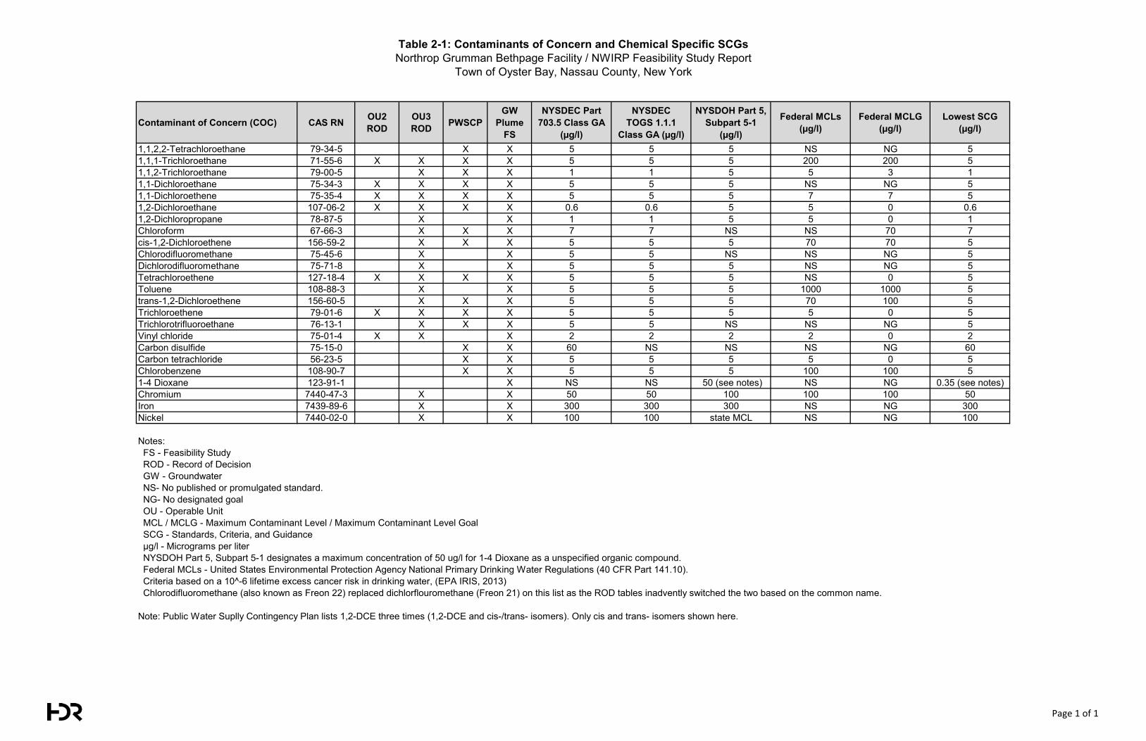
Table 2-1: Contaminants of Concern and Chemical Specific SCGsNorthrop Grumman Bethpage Facility / NWIRP Feasibility Study Report
Town of Oyster Bay, Nassau County, New York
Contaminant of Concern (COC) CAS RN OU2 ROD
OU3 ROD PWSCP
GW Plume
FS
NYSDEC Part 703.5 Class GA
(µg/l)
NYSDEC TOGS 1.1.1
Class GA (µg/l)
NYSDOH Part 5, Subpart 5-1
(µg/l)
Federal MCLs(µg/l)
Federal MCLG (µg/l)
Lowest SCG (µg/l)
1,1,2,2-Tetrachloroethane 79-34-5 X X 5 5 5 NS NG 51,1,1-Trichloroethane 71-55-6 X X X X 5 5 5 200 200 51,1,2-Trichloroethane 79-00-5 X X X 1 1 5 5 3 11,1-Dichloroethane 75-34-3 X X X X 5 5 5 NS NG 51,1-Dichloroethene 75-35-4 X X X X 5 5 5 7 7 51,2-Dichloroethane 107-06-2 X X X X 0.6 0.6 5 5 0 0.61,2-Dichloropropane 78-87-5 X X 1 1 5 5 0 1Chloroform 67-66-3 X X X 7 7 NS NS 70 7cis-1,2-Dichloroethene 156-59-2 X X X 5 5 5 70 70 5Chlorodifluoromethane 75-45-6 X X 5 5 NS NS NG 5Dichlorodifluoromethane 75-71-8 X X 5 5 5 NS NG 5Tetrachloroethene 127-18-4 X X X X 5 5 5 NS 0 5Toluene 108-88-3 X X 5 5 5 1000 1000 5trans-1,2-Dichloroethene 156-60-5 X X X 5 5 5 70 100 5Trichloroethene 79-01-6 X X X X 5 5 5 5 0 5Trichlorotrifluoroethane 76-13-1 X X X 5 5 NS NS NG 5Vinyl chloride 75-01-4 X X X 2 2 2 2 0 2Carbon disulfide 75-15-0 X X 60 NS NS NS NG 60Carbon tetrachloride 56-23-5 X X 5 5 5 5 0 5Chlorobenzene 108-90-7 X X 5 5 5 100 100 51-4 Dioxane 123-91-1 X NS NS 50 (see notes) NS NG 0.35 (see notes)Chromium 7440-47-3 X X 50 50 100 100 100 50Iron 7439-89-6 X X 300 300 300 NS NG 300Nickel 7440-02-0 X X 100 100 state MCL NS NG 100
Notes: FS - Feasibility Study ROD - Record of Decision GW - Groundwater NS- No published or promulgated standard. NG- No designated goal OU - Operable Unit MCL / MCLG - Maximum Contaminant Level / Maximum Contaminant Level Goal SCG - Standards, Criteria, and Guidance µg/l - Micrograms per liter NYSDOH Part 5, Subpart 5-1 designates a maximum concentration of 50 ug/l for 1-4 Dioxane as a unspecified organic compound. Federal MCLs - United States Environmental Protection Agency National Primary Drinking Water Regulations (40 CFR Part 141.10). Criteria based on a 10^-6 lifetime excess cancer risk in drinking water, (EPA IRIS, 2013) Chlorodifluoromethane (also known as Freon 22) replaced dichlorflouromethane (Freon 21) on this list as the ROD tables inadvently switched the two based on the common name.
Note: Public Water Suplly Contingency Plan lists 1,2-DCE three times (1,2-DCE and cis-/trans- isomers). Only cis and trans- isomers shown here.
Page 1 of 1
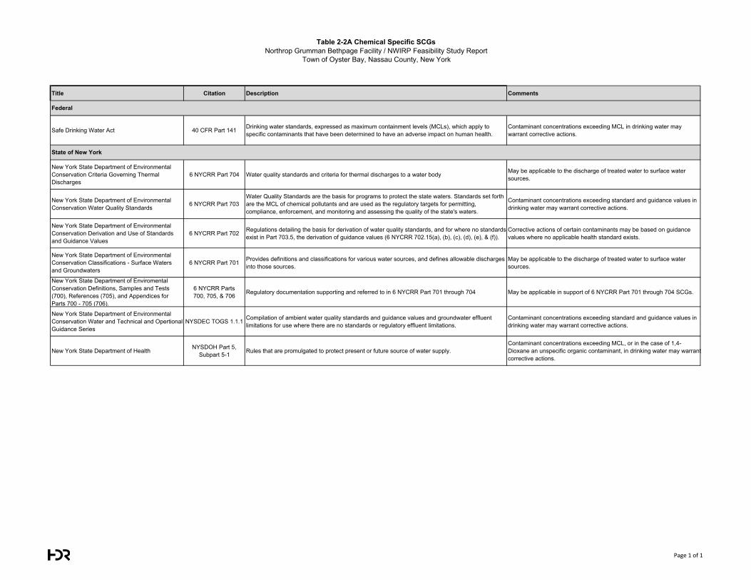
Table 2-2A Chemical Specific SCGsNorthrop Grumman Bethpage Facility / NWIRP Feasibility Study Report
Town of Oyster Bay, Nassau County, New York
Title Citation Description Comments
Safe Drinking Water Act 40 CFR Part 141 Drinking water standards, expressed as maximum containment levels (MCLs), which apply to specific contaminants that have been determined to have an adverse impact on human health.
Contaminant concentrations exceeding MCL in drinking water may warrant corrective actions.
New York State Department of Environmental Conservation Criteria Governing Thermal Discharges
6 NYCRR Part 704 Water quality standards and criteria for thermal discharges to a water body May be applicable to the discharge of treated water to surface water sources.
New York State Department of Environmental Conservation Water Quality Standards 6 NYCRR Part 703
Water Quality Standards are the basis for programs to protect the state waters. Standards set forth are the MCL of chemical pollutants and are used as the regulatory targets for permitting, compliance, enforcement, and monitoring and assessing the quality of the state's waters.
Contaminant concentrations exceeding standard and guidance values in drinking water may warrant corrective actions.
New York State Department of Environmental Conservation Derivation and Use of Standards and Guidance Values
6 NYCRR Part 702 Regulations detailing the basis for derivation of water quality standards, and for where no standards exist in Part 703.5, the derivation of guidance values (6 NYCRR 702.15(a), (b), (c), (d), (e), & (f)).
Corrective actions of certain contaminants may be based on guidance values where no applicable health standard exists.
New York State Department of Environmental Conservation Classifications - Surface Waters and Groundwaters
6 NYCRR Part 701 Provides definitions and classifications for various water sources, and defines allowable discharges into those sources.
May be applicable to the discharge of treated water to surface water sources.
New York State Department of Enviromental Conservation Definitions, Samples and Tests (700), References (705), and Appendices for Parts 700 - 705 (706).
6 NYCRR Parts 700, 705, & 706 Regulatory documentation supporting and referred to in 6 NYCRR Part 701 through 704 May be applicable in support of 6 NYCRR Part 701 through 704 SCGs.
New York State Department of Environmental Conservation Water and Technical and Opertional Guidance Series
NYSDEC TOGS 1.1.1 Compilation of ambient water quality standards and guidance values and groundwater effluent limitations for use where there are no standards or regulatory effluent limitations.
Contaminant concentrations exceeding standard and guidance values in drinking water may warrant corrective actions.
New York State Department of Health NYSDOH Part 5, Subpart 5-1 Rules that are promulgated to protect present or future source of water supply.
Contaminant concentrations exceeding MCL, or in the case of 1,4-Dioxane an unspecific organic contaminant, in drinking water may warrant corrective actions.
Federal
State of New York
Page 1 of 1
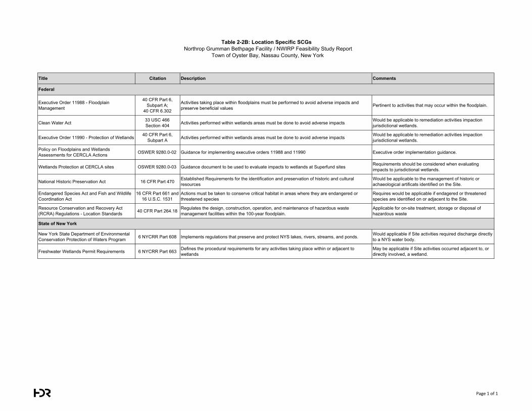
Table 2-2B: Location Specific SCGsNorthrop Grumman Bethpage Facility / NWIRP Feasibility Study Report
Town of Oyster Bay, Nassau County, New York
Title Citation Description Comments
Executive Order 11988 - Floodplain Management
40 CFR Part 6, Subpart A;
40 CFR 6.302
Activities taking place within floodplains must be performed to avoid adverse impacts and preserve beneficial values Pertinent to activities that may occur within the floodplain.
Clean Water Act 33 USC 466 Section 404 Activities performed within wetlands areas must be done to avoid adverse impacts Would be applicable to remediation activities impaction
jurisdictional wetlands.
Executive Order 11990 - Protection of Wetlands 40 CFR Part 6, Subpart A Activities performed within wetlands areas must be done to avoid adverse impacts Would be applicable to remediation activities impaction
jurisdictional wetlands.
Policy on Floodplains and Wetlands Assessments for CERCLA Actions OSWER 9280.0-02 Guidance for implementing executive orders 11988 and 11990 Executive order implementation guidance.
Wetlands Protection at CERCLA sites OSWER 9280.0-03 Guidance document to be used to evaluate impacts to wetlands at Superfund sites Requirements should be considered when evaluating impacts to jurisdictional wetlands.
National Historic Preservation Act 16 CFR Part 470 Established Requirements for the identification and preservation of historic and cultural resources
Would be applicable to the management of historic or achaeological artificats identified on the Site.
Endangered Species Act and Fish and Wildlife Coordination Act
16 CFR Part 661 and 16 U.S.C. 1531
Actions must be taken to conserve critical habitat in areas where they are endangered or threatened species
Requires would be applicable if endagered or threatened species are identified on or adjacent to the Site.
Resource Conservation and Recovery Act (RCRA) Regulations - Location Standards 40 CFR Part 264.18 Regulates the design, construction, operation, and maintenance of hazardous waste
management facilities within the 100-year floodplain.Applicable for on-site treatment, storage or disposal of hazardous waste
New York State Department of Environmental Conservation Protection of Waters Program 6 NYCRR Part 608 Implements regulations that preserve and protect NYS lakes, rivers, streams, and ponds. Would applicable if Site activities required discharge directly
to a NYS water body.
Freshwater Wetlands Permit Requirements 6 NYCRR Part 663 Defines the procedural requirements for any activities taking place within or adjacent to wetlands
May be applicable if Site activities occurred adjacent to, or directly involved, a wetland.
Federal
State of New York
Page 1 of 1
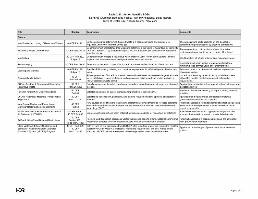
Table 2-2C: Action Specific SCGsNorthrop Grumman Bethpage Facility / NWIRP Feasibility Study Report
Town of Oyster Bay, Nassau County, New York
Title Citation Description Comments
Identification and Listing of Hazardous Wastes 40 CFR Part 261 Outlines criteria for determining if a solid waste is a hazardous waste and is subject to regulation under 40 CFR Parts 260 to 266
These regulations could apply for off-site disposal of contaminated groundwater or by-products of treatment
Hazardous Waste Determination 40 CFR Part 262.11Generators must characterize their wastes to determine if the waste is hazardous by listing (40 CFR 261, Subpart D) by characteristic (40 CFR 261, Subpart C) or excluded from regulation (40 CFR 261.4)
These regulations could apply for off-site disposal of contaminated groundwater or by-products of treatment
Manifesting 40 CFR Part 262, Subpart B
Generators must prepare a Hazardous waste Manifest (EPA FORM 8700-22) for all off-site shipments of hazardous waste to disposal and/or treatment facilities. Would apply to all off-site shipments of hazardous waste .
Recordkeeping 40 CFR Part 262.40 Generators must retain copies of an hazardous waste manifests used for off-site disposal Generator must retain copies of waste manifests for a minimum period of three years after shipment date.
Labeling and Marking 40 CFR Part 262 Subpart C
Specifies EPA naming, labeling and container requirements for off-site disposal of hazardous waste.
Pre-transportation requirements for off-site shipments of hazardous wastes.
Accumulation limitations 40 CFR Part 262.34
Allows generators of hazardous waste to store and treat hazardous wasteat the generation site for up to 90 days in tanks,containers, and containment buildings without having to obtain a RCRA hazardous waste permit.
Hazardous waste may be stored for up to 90 days on-site without the need to meet storage permit substantive requirements.
RCRA - Treatment, Storage and Disposal of Hazardous Waste
40 CFR Parts 264/265
Specifies requirements forthe operation of hazardous waste treatment, storage, and disposal facilities.
Applicablefor on-site hazardous waste treatment,storage, and disposal activities.
National Ambient Air Quality Standards 40 CFR Part 50 Establishes ambient air quality standards for protection of public health. May be applicable in evaluating air impacts during remedial
activities.USDOT Hazardous Materials Transportation Regulations
49 CFR Parts 171-180
Established classification, packaging, and labeling requirements for shipments of hazardous materials.
Applicable for the preparation of hazardous materials generated on-site for off-site shipment.
New Source Review and Prevention of Significant Deterioration Requirements
40 CFR Part 52
New sources or modifications whcich emit greater than defined thresholds for listed pollutants must perform ambient impact analyses and install controls w ich meet best availabe control technology (BACT)
Potentially applicable for certain remediation technologies and would require a comparison of potential emissions to theemission thresholds.
National Emissions Standards for Hazardous Air Pollutants (NESHAP)
40 CFR Part 61; 40 CFR Part 63 Source-specific regulations which establIsh emissions standards for hazardous air pollutants NSPS could be relevant and appropriate if regulated new
sources of air emissIons were to be established on site.
RCRA Subtitle C land Disposal Restrictions40 CFR
Section 6901; 40 CFR Part 268
Restricts land disposal of hazardous wastes that exceed specific criteria. Establishes Universal Treatment Standards to which hazardous waste must be treated prior to disposal.
Potentially applicable if hazardous residuals are generated from groundwater treatment.
Clean Water Act Effluent Guidelines and Standards; National Pollutant Discharge Elimination System (NPDES) Program
40 CFR Part 401; 40 CFR
Parts 122-125
Both on- and off-site dishcarges from CERCLA sites to surface waters are required to meet the substantive Clean Water Act limitations, monitorIng requirements, and best management practices. NPDES permits are required to discharge treated water to a surface water.
Applicable for discharges of groundwater to surface water bodies.
Federal
Page 1 of 2
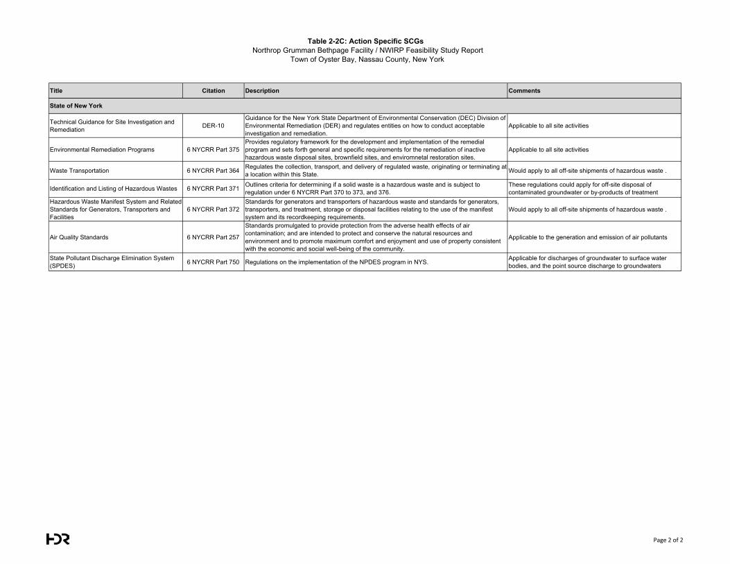
Table 2-2C: Action Specific SCGsNorthrop Grumman Bethpage Facility / NWIRP Feasibility Study Report
Town of Oyster Bay, Nassau County, New York
Title Citation Description Comments
Technical Guidance for Site Investigation and Remediation DER-10
Guidance for the New York State Department of Environmental Conservation (DEC) Division of Environmental Remediation (DER) and regulates entities on how to conduct acceptable investigation and remediation.
Applicable to all site activities
Environmental Remediation Programs 6 NYCRR Part 375Provides regulatory framework for the development and implementation of the remedial program and sets forth general and specific requirements for the remediation of inactive hazardous waste disposal sites, brownfield sites, and enviromnetal restoration sites.
Applicable to all site activities
Waste Transportation 6 NYCRR Part 364 Regulates the collection, transport, and delivery of regulated waste, originating or terminating at a location within this State. Would apply to all off-site shipments of hazardous waste .
Identification and Listing of Hazardous Wastes 6 NYCRR Part 371 Outlines criteria for determining if a solid waste is a hazardous waste and is subject to regulation under 6 NYCRR Part 370 to 373, and 376.
These regulations could apply for off-site disposal of contaminated groundwater or by-products of treatment
Hazardous Waste Manifest System and Related Standards for Generators, Transporters and Facilities
6 NYCRR Part 372Standards for generators and transporters of hazardous waste and standards for generators, transporters, and treatment, storage or disposal facilities relating to the use of the manifest system and its recordkeeping requirements.
Would apply to all off-site shipments of hazardous waste .
Air Quality Standards 6 NYCRR Part 257
Standards promulgated to provide protection from the adverse health effects of air contamination; and are intended to protect and conserve the natural resources and environment and to promote maximum comfort and enjoyment and use of property consistent with the economic and social well-being of the community.
Applicable to the generation and emission of air pollutants
State Pollutant Discharge Elimination System (SPDES) 6 NYCRR Part 750 Regulations on the implementation of the NPDES program in NYS. Applicable for discharges of groundwater to surface water
bodies, and the point source discharge to groundwaters
State of New York
Page 2 of 2
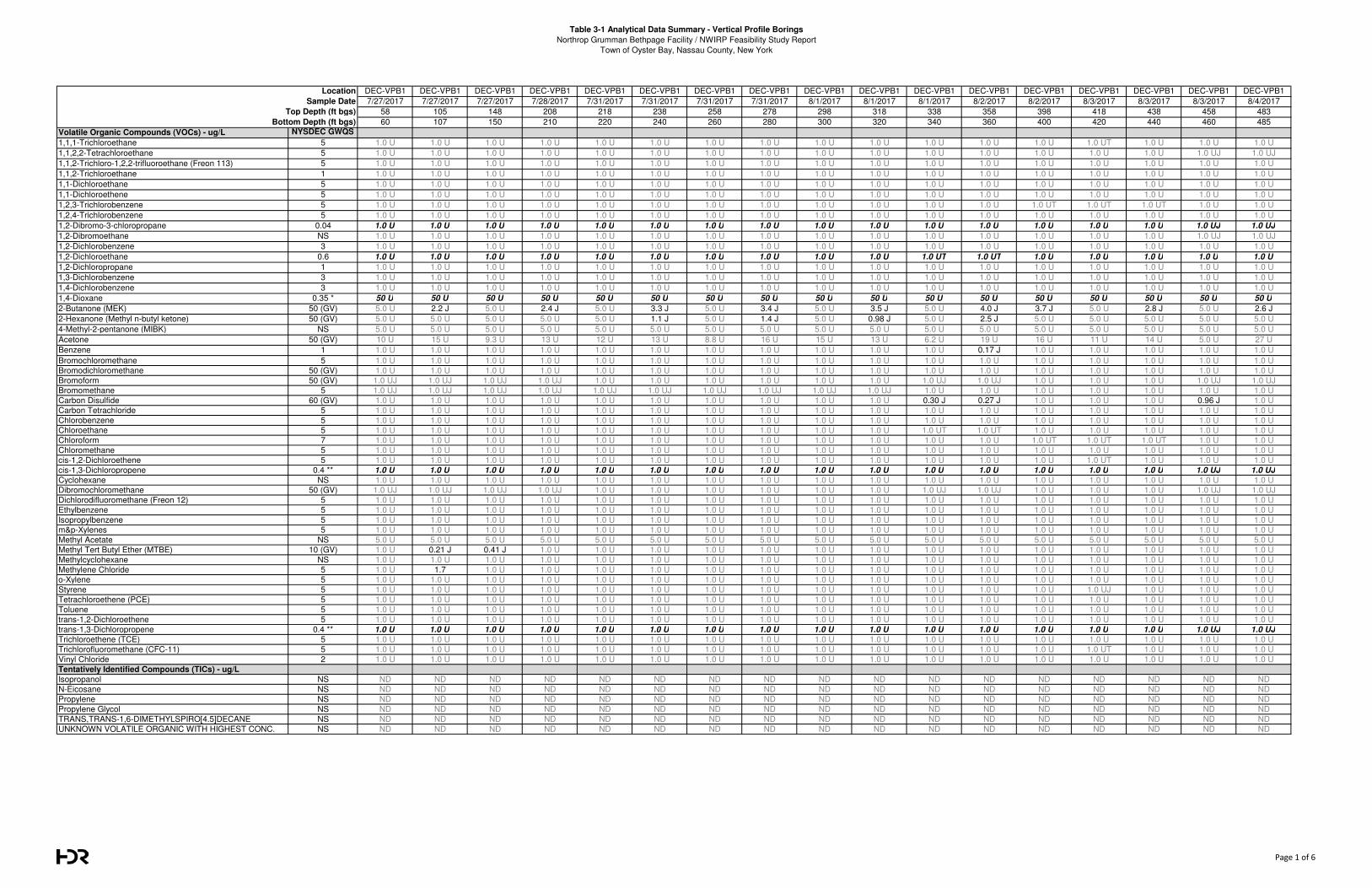
Table 3-1 Analytical Data Summary - Vertical Profile Borings
Northrop Grumman Bethpage Facility / NWIRP Feasibility Study Report
Town of Oyster Bay, Nassau County, New York
DEC-VPB1 DEC-VPB1 DEC-VPB1 DEC-VPB1 DEC-VPB1 DEC-VPB1 DEC-VPB1 DEC-VPB1 DEC-VPB1 DEC-VPB1 DEC-VPB1 DEC-VPB1 DEC-VPB1 DEC-VPB1 DEC-VPB1 DEC-VPB1 DEC-VPB1
7/27/2017 7/27/2017 7/27/2017 7/28/2017 7/31/2017 7/31/2017 7/31/2017 7/31/2017 8/1/2017 8/1/2017 8/1/2017 8/2/2017 8/2/2017 8/3/2017 8/3/2017 8/3/2017 8/4/2017
58 105 148 208 218 238 258 278 298 318 338 358 398 418 438 458 483
60 107 150 210 220 240 260 280 300 320 340 360 400 420 440 460 485
Volatile Organic Compounds (VOCs) - ug/L NYSDEC GWQS
1,1,1-Trichloroethane 5 1.0 U 1.0 U 1.0 U 1.0 U 1.0 U 1.0 U 1.0 U 1.0 U 1.0 U 1.0 U 1.0 U 1.0 U 1.0 U 1.0 UT 1.0 U 1.0 U 1.0 U
1,1,2,2-Tetrachloroethane 5 1.0 U 1.0 U 1.0 U 1.0 U 1.0 U 1.0 U 1.0 U 1.0 U 1.0 U 1.0 U 1.0 U 1.0 U 1.0 U 1.0 U 1.0 U 1.0 UJ 1.0 UJ
1,1,2-Trichloro-1,2,2-trifluoroethane (Freon 113) 5 1.0 U 1.0 U 1.0 U 1.0 U 1.0 U 1.0 U 1.0 U 1.0 U 1.0 U 1.0 U 1.0 U 1.0 U 1.0 U 1.0 U 1.0 U 1.0 U 1.0 U
1,1,2-Trichloroethane 1 1.0 U 1.0 U 1.0 U 1.0 U 1.0 U 1.0 U 1.0 U 1.0 U 1.0 U 1.0 U 1.0 U 1.0 U 1.0 U 1.0 U 1.0 U 1.0 U 1.0 U
1,1-Dichloroethane 5 1.0 U 1.0 U 1.0 U 1.0 U 1.0 U 1.0 U 1.0 U 1.0 U 1.0 U 1.0 U 1.0 U 1.0 U 1.0 U 1.0 U 1.0 U 1.0 U 1.0 U
1,1-Dichloroethene 5 1.0 U 1.0 U 1.0 U 1.0 U 1.0 U 1.0 U 1.0 U 1.0 U 1.0 U 1.0 U 1.0 U 1.0 U 1.0 U 1.0 U 1.0 U 1.0 U 1.0 U
1,2,3-Trichlorobenzene 5 1.0 U 1.0 U 1.0 U 1.0 U 1.0 U 1.0 U 1.0 U 1.0 U 1.0 U 1.0 U 1.0 U 1.0 U 1.0 UT 1.0 UT 1.0 UT 1.0 U 1.0 U
1,2,4-Trichlorobenzene 5 1.0 U 1.0 U 1.0 U 1.0 U 1.0 U 1.0 U 1.0 U 1.0 U 1.0 U 1.0 U 1.0 U 1.0 U 1.0 U 1.0 U 1.0 U 1.0 U 1.0 U
1,2-Dibromo-3-chloropropane 0.04 1.0 U 1.0 U 1.0 U 1.0 U 1.0 U 1.0 U 1.0 U 1.0 U 1.0 U 1.0 U 1.0 U 1.0 U 1.0 U 1.0 U 1.0 U 1.0 UJ 1.0 UJ
1,2-Dibromoethane NS 1.0 U 1.0 U 1.0 U 1.0 U 1.0 U 1.0 U 1.0 U 1.0 U 1.0 U 1.0 U 1.0 U 1.0 U 1.0 U 1.0 U 1.0 U 1.0 UJ 1.0 UJ
1,2-Dichlorobenzene 3 1.0 U 1.0 U 1.0 U 1.0 U 1.0 U 1.0 U 1.0 U 1.0 U 1.0 U 1.0 U 1.0 U 1.0 U 1.0 U 1.0 U 1.0 U 1.0 U 1.0 U
1,2-Dichloroethane 0.6 1.0 U 1.0 U 1.0 U 1.0 U 1.0 U 1.0 U 1.0 U 1.0 U 1.0 U 1.0 U 1.0 UT 1.0 UT 1.0 U 1.0 U 1.0 U 1.0 U 1.0 U
1,2-Dichloropropane 1 1.0 U 1.0 U 1.0 U 1.0 U 1.0 U 1.0 U 1.0 U 1.0 U 1.0 U 1.0 U 1.0 U 1.0 U 1.0 U 1.0 U 1.0 U 1.0 U 1.0 U
1,3-Dichlorobenzene 3 1.0 U 1.0 U 1.0 U 1.0 U 1.0 U 1.0 U 1.0 U 1.0 U 1.0 U 1.0 U 1.0 U 1.0 U 1.0 U 1.0 U 1.0 U 1.0 U 1.0 U
1,4-Dichlorobenzene 3 1.0 U 1.0 U 1.0 U 1.0 U 1.0 U 1.0 U 1.0 U 1.0 U 1.0 U 1.0 U 1.0 U 1.0 U 1.0 U 1.0 U 1.0 U 1.0 U 1.0 U
1,4-Dioxane 0.35 * 50 U 50 U 50 U 50 U 50 U 50 U 50 U 50 U 50 U 50 U 50 U 50 U 50 U 50 U 50 U 50 U 50 U
2-Butanone (MEK) 50 (GV) 5.0 U 2.2 J 5.0 U 2.4 J 5.0 U 3.3 J 5.0 U 3.4 J 5.0 U 3.5 J 5.0 U 4.0 J 3.7 J 5.0 U 2.8 J 5.0 U 2.6 J
2-Hexanone (Methyl n-butyl ketone) 50 (GV) 5.0 U 5.0 U 5.0 U 5.0 U 5.0 U 1.1 J 5.0 U 1.4 J 5.0 U 0.98 J 5.0 U 2.5 J 5.0 U 5.0 U 5.0 U 5.0 U 5.0 U
4-Methyl-2-pentanone (MIBK) NS 5.0 U 5.0 U 5.0 U 5.0 U 5.0 U 5.0 U 5.0 U 5.0 U 5.0 U 5.0 U 5.0 U 5.0 U 5.0 U 5.0 U 5.0 U 5.0 U 5.0 U
Acetone 50 (GV) 10 U 15 U 9.3 U 13 U 12 U 13 U 8.8 U 16 U 15 U 13 U 6.2 U 19 U 16 U 11 U 14 U 5.0 U 27 U
Benzene 1 1.0 U 1.0 U 1.0 U 1.0 U 1.0 U 1.0 U 1.0 U 1.0 U 1.0 U 1.0 U 1.0 U 0.17 J 1.0 U 1.0 U 1.0 U 1.0 U 1.0 U
Bromochloromethane 5 1.0 U 1.0 U 1.0 U 1.0 U 1.0 U 1.0 U 1.0 U 1.0 U 1.0 U 1.0 U 1.0 U 1.0 U 1.0 U 1.0 U 1.0 U 1.0 U 1.0 U
Bromodichloromethane 50 (GV) 1.0 U 1.0 U 1.0 U 1.0 U 1.0 U 1.0 U 1.0 U 1.0 U 1.0 U 1.0 U 1.0 U 1.0 U 1.0 U 1.0 U 1.0 U 1.0 U 1.0 U
Bromoform 50 (GV) 1.0 UJ 1.0 UJ 1.0 UJ 1.0 UJ 1.0 U 1.0 U 1.0 U 1.0 U 1.0 U 1.0 U 1.0 UJ 1.0 UJ 1.0 U 1.0 U 1.0 U 1.0 UJ 1.0 UJ
Bromomethane 5 1.0 UJ 1.0 UJ 1.0 UJ 1.0 UJ 1.0 UJ 1.0 UJ 1.0 UJ 1.0 UJ 1.0 UJ 1.0 UJ 1.0 U 1.0 U 1.0 U 1.0 U 1.0 U 1.0 U 1.0 U
Carbon Disulfide 60 (GV) 1.0 U 1.0 U 1.0 U 1.0 U 1.0 U 1.0 U 1.0 U 1.0 U 1.0 U 1.0 U 0.30 J 0.27 J 1.0 U 1.0 U 1.0 U 0.96 J 1.0 U
Carbon Tetrachloride 5 1.0 U 1.0 U 1.0 U 1.0 U 1.0 U 1.0 U 1.0 U 1.0 U 1.0 U 1.0 U 1.0 U 1.0 U 1.0 U 1.0 U 1.0 U 1.0 U 1.0 U
Chlorobenzene 5 1.0 U 1.0 U 1.0 U 1.0 U 1.0 U 1.0 U 1.0 U 1.0 U 1.0 U 1.0 U 1.0 U 1.0 U 1.0 U 1.0 U 1.0 U 1.0 U 1.0 U
Chloroethane 5 1.0 U 1.0 U 1.0 U 1.0 U 1.0 U 1.0 U 1.0 U 1.0 U 1.0 U 1.0 U 1.0 UT 1.0 UT 1.0 U 1.0 U 1.0 U 1.0 U 1.0 U
Chloroform 7 1.0 U 1.0 U 1.0 U 1.0 U 1.0 U 1.0 U 1.0 U 1.0 U 1.0 U 1.0 U 1.0 U 1.0 U 1.0 UT 1.0 UT 1.0 UT 1.0 U 1.0 U
Chloromethane 5 1.0 U 1.0 U 1.0 U 1.0 U 1.0 U 1.0 U 1.0 U 1.0 U 1.0 U 1.0 U 1.0 U 1.0 U 1.0 U 1.0 U 1.0 U 1.0 U 1.0 U
cis-1,2-Dichloroethene 5 1.0 U 1.0 U 1.0 U 1.0 U 1.0 U 1.0 U 1.0 U 1.0 U 1.0 U 1.0 U 1.0 U 1.0 U 1.0 U 1.0 UT 1.0 U 1.0 U 1.0 U
cis-1,3-Dichloropropene 0.4 ** 1.0 U 1.0 U 1.0 U 1.0 U 1.0 U 1.0 U 1.0 U 1.0 U 1.0 U 1.0 U 1.0 U 1.0 U 1.0 U 1.0 U 1.0 U 1.0 UJ 1.0 UJ
Cyclohexane NS 1.0 U 1.0 U 1.0 U 1.0 U 1.0 U 1.0 U 1.0 U 1.0 U 1.0 U 1.0 U 1.0 U 1.0 U 1.0 U 1.0 U 1.0 U 1.0 U 1.0 U
Dibromochloromethane 50 (GV) 1.0 UJ 1.0 UJ 1.0 UJ 1.0 UJ 1.0 U 1.0 U 1.0 U 1.0 U 1.0 U 1.0 U 1.0 UJ 1.0 UJ 1.0 U 1.0 U 1.0 U 1.0 UJ 1.0 UJ
Dichlorodifluoromethane (Freon 12) 5 1.0 U 1.0 U 1.0 U 1.0 U 1.0 U 1.0 U 1.0 U 1.0 U 1.0 U 1.0 U 1.0 U 1.0 U 1.0 U 1.0 U 1.0 U 1.0 U 1.0 U
Ethylbenzene 5 1.0 U 1.0 U 1.0 U 1.0 U 1.0 U 1.0 U 1.0 U 1.0 U 1.0 U 1.0 U 1.0 U 1.0 U 1.0 U 1.0 U 1.0 U 1.0 U 1.0 U
Isopropylbenzene 5 1.0 U 1.0 U 1.0 U 1.0 U 1.0 U 1.0 U 1.0 U 1.0 U 1.0 U 1.0 U 1.0 U 1.0 U 1.0 U 1.0 U 1.0 U 1.0 U 1.0 U
m&p-Xylenes 5 1.0 U 1.0 U 1.0 U 1.0 U 1.0 U 1.0 U 1.0 U 1.0 U 1.0 U 1.0 U 1.0 U 1.0 U 1.0 U 1.0 U 1.0 U 1.0 U 1.0 U
Methyl Acetate NS 5.0 U 5.0 U 5.0 U 5.0 U 5.0 U 5.0 U 5.0 U 5.0 U 5.0 U 5.0 U 5.0 U 5.0 U 5.0 U 5.0 U 5.0 U 5.0 U 5.0 U
Methyl Tert Butyl Ether (MTBE) 10 (GV) 1.0 U 0.21 J 0.41 J 1.0 U 1.0 U 1.0 U 1.0 U 1.0 U 1.0 U 1.0 U 1.0 U 1.0 U 1.0 U 1.0 U 1.0 U 1.0 U 1.0 U
Methylcyclohexane NS 1.0 U 1.0 U 1.0 U 1.0 U 1.0 U 1.0 U 1.0 U 1.0 U 1.0 U 1.0 U 1.0 U 1.0 U 1.0 U 1.0 U 1.0 U 1.0 U 1.0 U
Methylene Chloride 5 1.0 U 1.7 1.0 U 1.0 U 1.0 U 1.0 U 1.0 U 1.0 U 1.0 U 1.0 U 1.0 U 1.0 U 1.0 U 1.0 U 1.0 U 1.0 U 1.0 U
o-Xylene 5 1.0 U 1.0 U 1.0 U 1.0 U 1.0 U 1.0 U 1.0 U 1.0 U 1.0 U 1.0 U 1.0 U 1.0 U 1.0 U 1.0 U 1.0 U 1.0 U 1.0 U
Styrene 5 1.0 U 1.0 U 1.0 U 1.0 U 1.0 U 1.0 U 1.0 U 1.0 U 1.0 U 1.0 U 1.0 U 1.0 U 1.0 U 1.0 UJ 1.0 U 1.0 U 1.0 U
Tetrachloroethene (PCE) 5 1.0 U 1.0 U 1.0 U 1.0 U 1.0 U 1.0 U 1.0 U 1.0 U 1.0 U 1.0 U 1.0 U 1.0 U 1.0 U 1.0 U 1.0 U 1.0 U 1.0 U
Toluene 5 1.0 U 1.0 U 1.0 U 1.0 U 1.0 U 1.0 U 1.0 U 1.0 U 1.0 U 1.0 U 1.0 U 1.0 U 1.0 U 1.0 U 1.0 U 1.0 U 1.0 U
trans-1,2-Dichloroethene 5 1.0 U 1.0 U 1.0 U 1.0 U 1.0 U 1.0 U 1.0 U 1.0 U 1.0 U 1.0 U 1.0 U 1.0 U 1.0 U 1.0 U 1.0 U 1.0 U 1.0 U
trans-1,3-Dichloropropene 0.4 ** 1.0 U 1.0 U 1.0 U 1.0 U 1.0 U 1.0 U 1.0 U 1.0 U 1.0 U 1.0 U 1.0 U 1.0 U 1.0 U 1.0 U 1.0 U 1.0 UJ 1.0 UJ
Trichloroethene (TCE) 5 1.0 U 1.0 U 1.0 U 1.0 U 1.0 U 1.0 U 1.0 U 1.0 U 1.0 U 1.0 U 1.0 U 1.0 U 1.0 U 1.0 U 1.0 U 1.0 U 1.0 U
Trichlorofluoromethane (CFC-11) 5 1.0 U 1.0 U 1.0 U 1.0 U 1.0 U 1.0 U 1.0 U 1.0 U 1.0 U 1.0 U 1.0 U 1.0 U 1.0 U 1.0 UT 1.0 U 1.0 U 1.0 U
Vinyl Chloride 2 1.0 U 1.0 U 1.0 U 1.0 U 1.0 U 1.0 U 1.0 U 1.0 U 1.0 U 1.0 U 1.0 U 1.0 U 1.0 U 1.0 U 1.0 U 1.0 U 1.0 U
Tentatively Identified Compounds (TICs) - ug/L
Isopropanol NS ND ND ND ND ND ND ND ND ND ND ND ND ND ND ND ND ND
N-Eicosane NS ND ND ND ND ND ND ND ND ND ND ND ND ND ND ND ND ND
Propylene NS ND ND ND ND ND ND ND ND ND ND ND ND ND ND ND ND ND
Propylene Glycol NS ND ND ND ND ND ND ND ND ND ND ND ND ND ND ND ND ND
TRANS,TRANS-1,6-DIMETHYLSPIRO[4.5]DECANE NS ND ND ND ND ND ND ND ND ND ND ND ND ND ND ND ND ND
UNKNOWN VOLATILE ORGANIC WITH HIGHEST CONC. NS ND ND ND ND ND ND ND ND ND ND ND ND ND ND ND ND ND
Location
Sample Date
Top Depth (ft bgs)
Bottom Depth (ft bgs)
Page 1 of 6
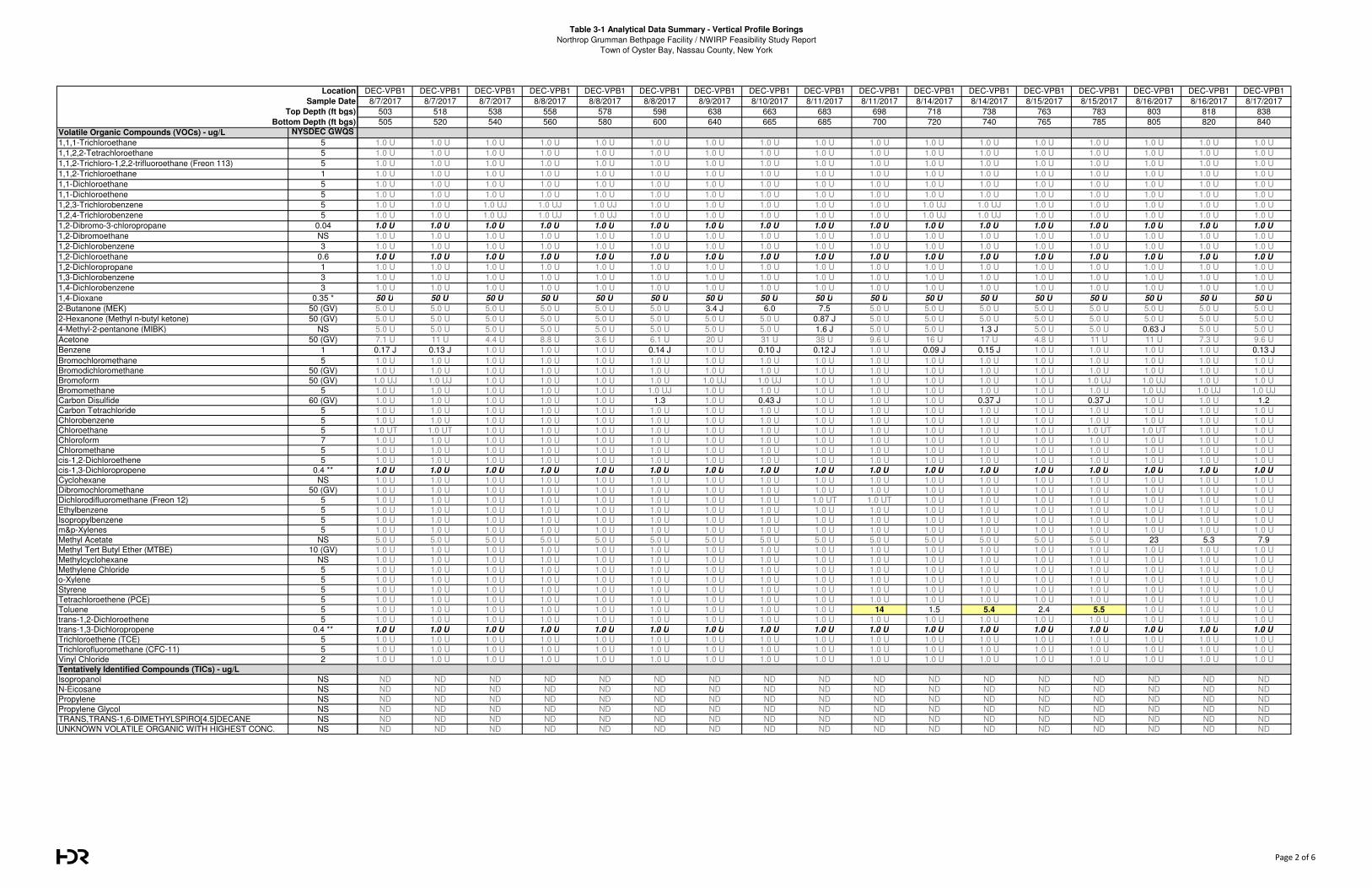
Table 3-1 Analytical Data Summary - Vertical Profile Borings
Northrop Grumman Bethpage Facility / NWIRP Feasibility Study Report
Town of Oyster Bay, Nassau County, New York
Volatile Organic Compounds (VOCs) - ug/L NYSDEC GWQS
1,1,1-Trichloroethane 5
1,1,2,2-Tetrachloroethane 5
1,1,2-Trichloro-1,2,2-trifluoroethane (Freon 113) 5
1,1,2-Trichloroethane 1
1,1-Dichloroethane 5
1,1-Dichloroethene 5
1,2,3-Trichlorobenzene 5
1,2,4-Trichlorobenzene 5
1,2-Dibromo-3-chloropropane 0.04
1,2-Dibromoethane NS
1,2-Dichlorobenzene 3
1,2-Dichloroethane 0.6
1,2-Dichloropropane 1
1,3-Dichlorobenzene 3
1,4-Dichlorobenzene 3
1,4-Dioxane 0.35 *
2-Butanone (MEK) 50 (GV)
2-Hexanone (Methyl n-butyl ketone) 50 (GV)
4-Methyl-2-pentanone (MIBK) NS
Acetone 50 (GV)
Benzene 1
Bromochloromethane 5
Bromodichloromethane 50 (GV)
Bromoform 50 (GV)
Bromomethane 5
Carbon Disulfide 60 (GV)
Carbon Tetrachloride 5
Chlorobenzene 5
Chloroethane 5
Chloroform 7
Chloromethane 5
cis-1,2-Dichloroethene 5
cis-1,3-Dichloropropene 0.4 **
Cyclohexane NS
Dibromochloromethane 50 (GV)
Dichlorodifluoromethane (Freon 12) 5
Ethylbenzene 5
Isopropylbenzene 5
m&p-Xylenes 5
Methyl Acetate NS
Methyl Tert Butyl Ether (MTBE) 10 (GV)
Methylcyclohexane NS
Methylene Chloride 5
o-Xylene 5
Styrene 5
Tetrachloroethene (PCE) 5
Toluene 5
trans-1,2-Dichloroethene 5
trans-1,3-Dichloropropene 0.4 **
Trichloroethene (TCE) 5
Trichlorofluoromethane (CFC-11) 5
Vinyl Chloride 2
Tentatively Identified Compounds (TICs) - ug/L
Isopropanol NS
N-Eicosane NS
Propylene NS
Propylene Glycol NS
TRANS,TRANS-1,6-DIMETHYLSPIRO[4.5]DECANE NS
UNKNOWN VOLATILE ORGANIC WITH HIGHEST CONC. NS
Location
Sample Date
Top Depth (ft bgs)
Bottom Depth (ft bgs)
DEC-VPB1 DEC-VPB1 DEC-VPB1 DEC-VPB1 DEC-VPB1 DEC-VPB1 DEC-VPB1 DEC-VPB1 DEC-VPB1 DEC-VPB1 DEC-VPB1 DEC-VPB1 DEC-VPB1 DEC-VPB1 DEC-VPB1 DEC-VPB1 DEC-VPB1
8/7/2017 8/7/2017 8/7/2017 8/8/2017 8/8/2017 8/8/2017 8/9/2017 8/10/2017 8/11/2017 8/11/2017 8/14/2017 8/14/2017 8/15/2017 8/15/2017 8/16/2017 8/16/2017 8/17/2017
503 518 538 558 578 598 638 663 683 698 718 738 763 783 803 818 838
505 520 540 560 580 600 640 665 685 700 720 740 765 785 805 820 840
1.0 U 1.0 U 1.0 U 1.0 U 1.0 U 1.0 U 1.0 U 1.0 U 1.0 U 1.0 U 1.0 U 1.0 U 1.0 U 1.0 U 1.0 U 1.0 U 1.0 U
1.0 U 1.0 U 1.0 U 1.0 U 1.0 U 1.0 U 1.0 U 1.0 U 1.0 U 1.0 U 1.0 U 1.0 U 1.0 U 1.0 U 1.0 U 1.0 U 1.0 U
1.0 U 1.0 U 1.0 U 1.0 U 1.0 U 1.0 U 1.0 U 1.0 U 1.0 U 1.0 U 1.0 U 1.0 U 1.0 U 1.0 U 1.0 U 1.0 U 1.0 U
1.0 U 1.0 U 1.0 U 1.0 U 1.0 U 1.0 U 1.0 U 1.0 U 1.0 U 1.0 U 1.0 U 1.0 U 1.0 U 1.0 U 1.0 U 1.0 U 1.0 U
1.0 U 1.0 U 1.0 U 1.0 U 1.0 U 1.0 U 1.0 U 1.0 U 1.0 U 1.0 U 1.0 U 1.0 U 1.0 U 1.0 U 1.0 U 1.0 U 1.0 U
1.0 U 1.0 U 1.0 U 1.0 U 1.0 U 1.0 U 1.0 U 1.0 U 1.0 U 1.0 U 1.0 U 1.0 U 1.0 U 1.0 U 1.0 U 1.0 U 1.0 U
1.0 U 1.0 U 1.0 UJ 1.0 UJ 1.0 UJ 1.0 U 1.0 U 1.0 U 1.0 U 1.0 U 1.0 UJ 1.0 UJ 1.0 U 1.0 U 1.0 U 1.0 U 1.0 U
1.0 U 1.0 U 1.0 UJ 1.0 UJ 1.0 UJ 1.0 U 1.0 U 1.0 U 1.0 U 1.0 U 1.0 UJ 1.0 UJ 1.0 U 1.0 U 1.0 U 1.0 U 1.0 U
1.0 U 1.0 U 1.0 U 1.0 U 1.0 U 1.0 U 1.0 U 1.0 U 1.0 U 1.0 U 1.0 U 1.0 U 1.0 U 1.0 U 1.0 U 1.0 U 1.0 U
1.0 U 1.0 U 1.0 U 1.0 U 1.0 U 1.0 U 1.0 U 1.0 U 1.0 U 1.0 U 1.0 U 1.0 U 1.0 U 1.0 U 1.0 U 1.0 U 1.0 U
1.0 U 1.0 U 1.0 U 1.0 U 1.0 U 1.0 U 1.0 U 1.0 U 1.0 U 1.0 U 1.0 U 1.0 U 1.0 U 1.0 U 1.0 U 1.0 U 1.0 U
1.0 U 1.0 U 1.0 U 1.0 U 1.0 U 1.0 U 1.0 U 1.0 U 1.0 U 1.0 U 1.0 U 1.0 U 1.0 U 1.0 U 1.0 U 1.0 U 1.0 U
1.0 U 1.0 U 1.0 U 1.0 U 1.0 U 1.0 U 1.0 U 1.0 U 1.0 U 1.0 U 1.0 U 1.0 U 1.0 U 1.0 U 1.0 U 1.0 U 1.0 U
1.0 U 1.0 U 1.0 U 1.0 U 1.0 U 1.0 U 1.0 U 1.0 U 1.0 U 1.0 U 1.0 U 1.0 U 1.0 U 1.0 U 1.0 U 1.0 U 1.0 U
1.0 U 1.0 U 1.0 U 1.0 U 1.0 U 1.0 U 1.0 U 1.0 U 1.0 U 1.0 U 1.0 U 1.0 U 1.0 U 1.0 U 1.0 U 1.0 U 1.0 U
50 U 50 U 50 U 50 U 50 U 50 U 50 U 50 U 50 U 50 U 50 U 50 U 50 U 50 U 50 U 50 U 50 U
5.0 U 5.0 U 5.0 U 5.0 U 5.0 U 5.0 U 3.4 J 6.0 7.5 5.0 U 5.0 U 5.0 U 5.0 U 5.0 U 5.0 U 5.0 U 5.0 U
5.0 U 5.0 U 5.0 U 5.0 U 5.0 U 5.0 U 5.0 U 5.0 U 0.87 J 5.0 U 5.0 U 5.0 U 5.0 U 5.0 U 5.0 U 5.0 U 5.0 U
5.0 U 5.0 U 5.0 U 5.0 U 5.0 U 5.0 U 5.0 U 5.0 U 1.6 J 5.0 U 5.0 U 1.3 J 5.0 U 5.0 U 0.63 J 5.0 U 5.0 U
7.1 U 11 U 4.4 U 8.8 U 3.6 U 6.1 U 20 U 31 U 38 U 9.6 U 16 U 17 U 4.8 U 11 U 11 U 7.3 U 9.6 U
0.17 J 0.13 J 1.0 U 1.0 U 1.0 U 0.14 J 1.0 U 0.10 J 0.12 J 1.0 U 0.09 J 0.15 J 1.0 U 1.0 U 1.0 U 1.0 U 0.13 J
1.0 U 1.0 U 1.0 U 1.0 U 1.0 U 1.0 U 1.0 U 1.0 U 1.0 U 1.0 U 1.0 U 1.0 U 1.0 U 1.0 U 1.0 U 1.0 U 1.0 U
1.0 U 1.0 U 1.0 U 1.0 U 1.0 U 1.0 U 1.0 U 1.0 U 1.0 U 1.0 U 1.0 U 1.0 U 1.0 U 1.0 U 1.0 U 1.0 U 1.0 U
1.0 UJ 1.0 UJ 1.0 U 1.0 U 1.0 U 1.0 U 1.0 UJ 1.0 UJ 1.0 U 1.0 U 1.0 U 1.0 U 1.0 U 1.0 UJ 1.0 UJ 1.0 U 1.0 U
1.0 U 1.0 U 1.0 U 1.0 U 1.0 U 1.0 UJ 1.0 U 1.0 U 1.0 U 1.0 U 1.0 U 1.0 U 1.0 U 1.0 U 1.0 UJ 1.0 UJ 1.0 UJ
1.0 U 1.0 U 1.0 U 1.0 U 1.0 U 1.3 1.0 U 0.43 J 1.0 U 1.0 U 1.0 U 0.37 J 1.0 U 0.37 J 1.0 U 1.0 U 1.2
1.0 U 1.0 U 1.0 U 1.0 U 1.0 U 1.0 U 1.0 U 1.0 U 1.0 U 1.0 U 1.0 U 1.0 U 1.0 U 1.0 U 1.0 U 1.0 U 1.0 U
1.0 U 1.0 U 1.0 U 1.0 U 1.0 U 1.0 U 1.0 U 1.0 U 1.0 U 1.0 U 1.0 U 1.0 U 1.0 U 1.0 U 1.0 U 1.0 U 1.0 U
1.0 UT 1.0 UT 1.0 U 1.0 U 1.0 U 1.0 U 1.0 U 1.0 U 1.0 U 1.0 U 1.0 U 1.0 U 1.0 U 1.0 UT 1.0 UT 1.0 U 1.0 U
1.0 U 1.0 U 1.0 U 1.0 U 1.0 U 1.0 U 1.0 U 1.0 U 1.0 U 1.0 U 1.0 U 1.0 U 1.0 U 1.0 U 1.0 U 1.0 U 1.0 U
1.0 U 1.0 U 1.0 U 1.0 U 1.0 U 1.0 U 1.0 U 1.0 U 1.0 U 1.0 U 1.0 U 1.0 U 1.0 U 1.0 U 1.0 U 1.0 U 1.0 U
1.0 U 1.0 U 1.0 U 1.0 U 1.0 U 1.0 U 1.0 U 1.0 U 1.0 U 1.0 U 1.0 U 1.0 U 1.0 U 1.0 U 1.0 U 1.0 U 1.0 U
1.0 U 1.0 U 1.0 U 1.0 U 1.0 U 1.0 U 1.0 U 1.0 U 1.0 U 1.0 U 1.0 U 1.0 U 1.0 U 1.0 U 1.0 U 1.0 U 1.0 U
1.0 U 1.0 U 1.0 U 1.0 U 1.0 U 1.0 U 1.0 U 1.0 U 1.0 U 1.0 U 1.0 U 1.0 U 1.0 U 1.0 U 1.0 U 1.0 U 1.0 U
1.0 U 1.0 U 1.0 U 1.0 U 1.0 U 1.0 U 1.0 U 1.0 U 1.0 U 1.0 U 1.0 U 1.0 U 1.0 U 1.0 U 1.0 U 1.0 U 1.0 U
1.0 U 1.0 U 1.0 U 1.0 U 1.0 U 1.0 U 1.0 U 1.0 U 1.0 UT 1.0 UT 1.0 U 1.0 U 1.0 U 1.0 U 1.0 U 1.0 U 1.0 U
1.0 U 1.0 U 1.0 U 1.0 U 1.0 U 1.0 U 1.0 U 1.0 U 1.0 U 1.0 U 1.0 U 1.0 U 1.0 U 1.0 U 1.0 U 1.0 U 1.0 U
1.0 U 1.0 U 1.0 U 1.0 U 1.0 U 1.0 U 1.0 U 1.0 U 1.0 U 1.0 U 1.0 U 1.0 U 1.0 U 1.0 U 1.0 U 1.0 U 1.0 U
1.0 U 1.0 U 1.0 U 1.0 U 1.0 U 1.0 U 1.0 U 1.0 U 1.0 U 1.0 U 1.0 U 1.0 U 1.0 U 1.0 U 1.0 U 1.0 U 1.0 U
5.0 U 5.0 U 5.0 U 5.0 U 5.0 U 5.0 U 5.0 U 5.0 U 5.0 U 5.0 U 5.0 U 5.0 U 5.0 U 5.0 U 23 5.3 7.9
1.0 U 1.0 U 1.0 U 1.0 U 1.0 U 1.0 U 1.0 U 1.0 U 1.0 U 1.0 U 1.0 U 1.0 U 1.0 U 1.0 U 1.0 U 1.0 U 1.0 U
1.0 U 1.0 U 1.0 U 1.0 U 1.0 U 1.0 U 1.0 U 1.0 U 1.0 U 1.0 U 1.0 U 1.0 U 1.0 U 1.0 U 1.0 U 1.0 U 1.0 U
1.0 U 1.0 U 1.0 U 1.0 U 1.0 U 1.0 U 1.0 U 1.0 U 1.0 U 1.0 U 1.0 U 1.0 U 1.0 U 1.0 U 1.0 U 1.0 U 1.0 U
1.0 U 1.0 U 1.0 U 1.0 U 1.0 U 1.0 U 1.0 U 1.0 U 1.0 U 1.0 U 1.0 U 1.0 U 1.0 U 1.0 U 1.0 U 1.0 U 1.0 U
1.0 U 1.0 U 1.0 U 1.0 U 1.0 U 1.0 U 1.0 U 1.0 U 1.0 U 1.0 U 1.0 U 1.0 U 1.0 U 1.0 U 1.0 U 1.0 U 1.0 U
1.0 U 1.0 U 1.0 U 1.0 U 1.0 U 1.0 U 1.0 U 1.0 U 1.0 U 1.0 U 1.0 U 1.0 U 1.0 U 1.0 U 1.0 U 1.0 U 1.0 U
1.0 U 1.0 U 1.0 U 1.0 U 1.0 U 1.0 U 1.0 U 1.0 U 1.0 U 14 1.5 5.4 2.4 5.5 1.0 U 1.0 U 1.0 U
1.0 U 1.0 U 1.0 U 1.0 U 1.0 U 1.0 U 1.0 U 1.0 U 1.0 U 1.0 U 1.0 U 1.0 U 1.0 U 1.0 U 1.0 U 1.0 U 1.0 U
1.0 U 1.0 U 1.0 U 1.0 U 1.0 U 1.0 U 1.0 U 1.0 U 1.0 U 1.0 U 1.0 U 1.0 U 1.0 U 1.0 U 1.0 U 1.0 U 1.0 U
1.0 U 1.0 U 1.0 U 1.0 U 1.0 U 1.0 U 1.0 U 1.0 U 1.0 U 1.0 U 1.0 U 1.0 U 1.0 U 1.0 U 1.0 U 1.0 U 1.0 U
1.0 U 1.0 U 1.0 U 1.0 U 1.0 U 1.0 U 1.0 U 1.0 U 1.0 U 1.0 U 1.0 U 1.0 U 1.0 U 1.0 U 1.0 U 1.0 U 1.0 U
1.0 U 1.0 U 1.0 U 1.0 U 1.0 U 1.0 U 1.0 U 1.0 U 1.0 U 1.0 U 1.0 U 1.0 U 1.0 U 1.0 U 1.0 U 1.0 U 1.0 U
ND ND ND ND ND ND ND ND ND ND ND ND ND ND ND ND ND
ND ND ND ND ND ND ND ND ND ND ND ND ND ND ND ND ND
ND ND ND ND ND ND ND ND ND ND ND ND ND ND ND ND ND
ND ND ND ND ND ND ND ND ND ND ND ND ND ND ND ND ND
ND ND ND ND ND ND ND ND ND ND ND ND ND ND ND ND ND
ND ND ND ND ND ND ND ND ND ND ND ND ND ND ND ND ND
Page 2 of 6
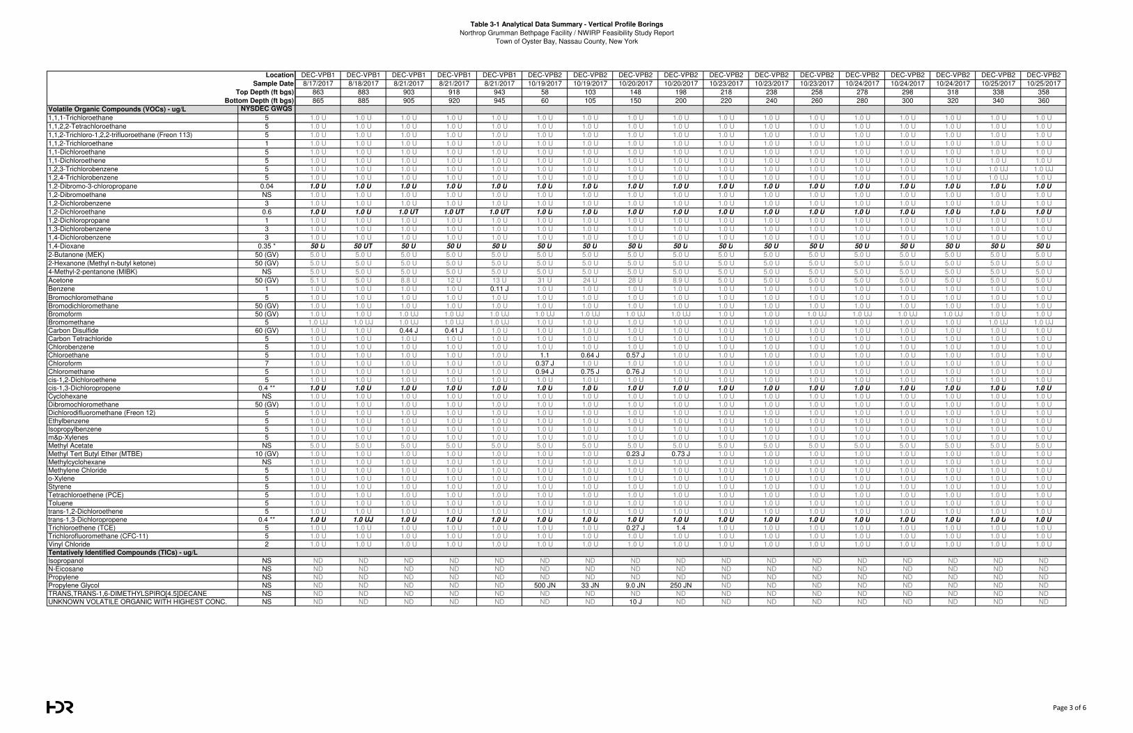
Table 3-1 Analytical Data Summary - Vertical Profile Borings
Northrop Grumman Bethpage Facility / NWIRP Feasibility Study Report
Town of Oyster Bay, Nassau County, New York
Volatile Organic Compounds (VOCs) - ug/L NYSDEC GWQS
1,1,1-Trichloroethane 5
1,1,2,2-Tetrachloroethane 5
1,1,2-Trichloro-1,2,2-trifluoroethane (Freon 113) 5
1,1,2-Trichloroethane 1
1,1-Dichloroethane 5
1,1-Dichloroethene 5
1,2,3-Trichlorobenzene 5
1,2,4-Trichlorobenzene 5
1,2-Dibromo-3-chloropropane 0.04
1,2-Dibromoethane NS
1,2-Dichlorobenzene 3
1,2-Dichloroethane 0.6
1,2-Dichloropropane 1
1,3-Dichlorobenzene 3
1,4-Dichlorobenzene 3
1,4-Dioxane 0.35 *
2-Butanone (MEK) 50 (GV)
2-Hexanone (Methyl n-butyl ketone) 50 (GV)
4-Methyl-2-pentanone (MIBK) NS
Acetone 50 (GV)
Benzene 1
Bromochloromethane 5
Bromodichloromethane 50 (GV)
Bromoform 50 (GV)
Bromomethane 5
Carbon Disulfide 60 (GV)
Carbon Tetrachloride 5
Chlorobenzene 5
Chloroethane 5
Chloroform 7
Chloromethane 5
cis-1,2-Dichloroethene 5
cis-1,3-Dichloropropene 0.4 **
Cyclohexane NS
Dibromochloromethane 50 (GV)
Dichlorodifluoromethane (Freon 12) 5
Ethylbenzene 5
Isopropylbenzene 5
m&p-Xylenes 5
Methyl Acetate NS
Methyl Tert Butyl Ether (MTBE) 10 (GV)
Methylcyclohexane NS
Methylene Chloride 5
o-Xylene 5
Styrene 5
Tetrachloroethene (PCE) 5
Toluene 5
trans-1,2-Dichloroethene 5
trans-1,3-Dichloropropene 0.4 **
Trichloroethene (TCE) 5
Trichlorofluoromethane (CFC-11) 5
Vinyl Chloride 2
Tentatively Identified Compounds (TICs) - ug/L
Isopropanol NS
N-Eicosane NS
Propylene NS
Propylene Glycol NS
TRANS,TRANS-1,6-DIMETHYLSPIRO[4.5]DECANE NS
UNKNOWN VOLATILE ORGANIC WITH HIGHEST CONC. NS
Location
Sample Date
Top Depth (ft bgs)
Bottom Depth (ft bgs)
DEC-VPB1 DEC-VPB1 DEC-VPB1 DEC-VPB1 DEC-VPB1 DEC-VPB2 DEC-VPB2 DEC-VPB2 DEC-VPB2 DEC-VPB2 DEC-VPB2 DEC-VPB2 DEC-VPB2 DEC-VPB2 DEC-VPB2 DEC-VPB2 DEC-VPB2
8/17/2017 8/18/2017 8/21/2017 8/21/2017 8/21/2017 10/19/2017 10/19/2017 10/20/2017 10/20/2017 10/23/2017 10/23/2017 10/23/2017 10/24/2017 10/24/2017 10/24/2017 10/25/2017 10/25/2017
863 883 903 918 943 58 103 148 198 218 238 258 278 298 318 338 358
865 885 905 920 945 60 105 150 200 220 240 260 280 300 320 340 360
1.0 U 1.0 U 1.0 U 1.0 U 1.0 U 1.0 U 1.0 U 1.0 U 1.0 U 1.0 U 1.0 U 1.0 U 1.0 U 1.0 U 1.0 U 1.0 U 1.0 U
1.0 U 1.0 U 1.0 U 1.0 U 1.0 U 1.0 U 1.0 U 1.0 U 1.0 U 1.0 U 1.0 U 1.0 U 1.0 U 1.0 U 1.0 U 1.0 U 1.0 U
1.0 U 1.0 U 1.0 U 1.0 U 1.0 U 1.0 U 1.0 U 1.0 U 1.0 U 1.0 U 1.0 U 1.0 U 1.0 U 1.0 U 1.0 U 1.0 U 1.0 U
1.0 U 1.0 U 1.0 U 1.0 U 1.0 U 1.0 U 1.0 U 1.0 U 1.0 U 1.0 U 1.0 U 1.0 U 1.0 U 1.0 U 1.0 U 1.0 U 1.0 U
1.0 U 1.0 U 1.0 U 1.0 U 1.0 U 1.0 U 1.0 U 1.0 U 1.0 U 1.0 U 1.0 U 1.0 U 1.0 U 1.0 U 1.0 U 1.0 U 1.0 U
1.0 U 1.0 U 1.0 U 1.0 U 1.0 U 1.0 U 1.0 U 1.0 U 1.0 U 1.0 U 1.0 U 1.0 U 1.0 U 1.0 U 1.0 U 1.0 U 1.0 U
1.0 U 1.0 U 1.0 U 1.0 U 1.0 U 1.0 U 1.0 U 1.0 U 1.0 U 1.0 U 1.0 U 1.0 U 1.0 U 1.0 U 1.0 U 1.0 UJ 1.0 UJ
1.0 U 1.0 U 1.0 U 1.0 U 1.0 U 1.0 U 1.0 U 1.0 U 1.0 U 1.0 U 1.0 U 1.0 U 1.0 U 1.0 U 1.0 U 1.0 UJ 1.0 U
1.0 U 1.0 U 1.0 U 1.0 U 1.0 U 1.0 U 1.0 U 1.0 U 1.0 U 1.0 U 1.0 U 1.0 U 1.0 U 1.0 U 1.0 U 1.0 U 1.0 U
1.0 U 1.0 U 1.0 U 1.0 U 1.0 U 1.0 U 1.0 U 1.0 U 1.0 U 1.0 U 1.0 U 1.0 U 1.0 U 1.0 U 1.0 U 1.0 U 1.0 U
1.0 U 1.0 U 1.0 U 1.0 U 1.0 U 1.0 U 1.0 U 1.0 U 1.0 U 1.0 U 1.0 U 1.0 U 1.0 U 1.0 U 1.0 U 1.0 U 1.0 U
1.0 U 1.0 U 1.0 UT 1.0 UT 1.0 UT 1.0 U 1.0 U 1.0 U 1.0 U 1.0 U 1.0 U 1.0 U 1.0 U 1.0 U 1.0 U 1.0 U 1.0 U
1.0 U 1.0 U 1.0 U 1.0 U 1.0 U 1.0 U 1.0 U 1.0 U 1.0 U 1.0 U 1.0 U 1.0 U 1.0 U 1.0 U 1.0 U 1.0 U 1.0 U
1.0 U 1.0 U 1.0 U 1.0 U 1.0 U 1.0 U 1.0 U 1.0 U 1.0 U 1.0 U 1.0 U 1.0 U 1.0 U 1.0 U 1.0 U 1.0 U 1.0 U
1.0 U 1.0 U 1.0 U 1.0 U 1.0 U 1.0 U 1.0 U 1.0 U 1.0 U 1.0 U 1.0 U 1.0 U 1.0 U 1.0 U 1.0 U 1.0 U 1.0 U
50 U 50 UT 50 U 50 U 50 U 50 U 50 U 50 U 50 U 50 U 50 U 50 U 50 U 50 U 50 U 50 U 50 U
5.0 U 5.0 U 5.0 U 5.0 U 5.0 U 5.0 U 5.0 U 5.0 U 5.0 U 5.0 U 5.0 U 5.0 U 5.0 U 5.0 U 5.0 U 5.0 U 5.0 U
5.0 U 5.0 U 5.0 U 5.0 U 5.0 U 5.0 U 5.0 U 5.0 U 5.0 U 5.0 U 5.0 U 5.0 U 5.0 U 5.0 U 5.0 U 5.0 U 5.0 U
5.0 U 5.0 U 5.0 U 5.0 U 5.0 U 5.0 U 5.0 U 5.0 U 5.0 U 5.0 U 5.0 U 5.0 U 5.0 U 5.0 U 5.0 U 5.0 U 5.0 U
5.1 U 5.0 U 8.8 U 12 U 13 U 31 U 24 U 28 U 8.9 U 5.0 U 5.0 U 5.0 U 5.0 U 5.0 U 5.0 U 5.0 U 5.0 U
1.0 U 1.0 U 1.0 U 1.0 U 0.11 J 1.0 U 1.0 U 1.0 U 1.0 U 1.0 U 1.0 U 1.0 U 1.0 U 1.0 U 1.0 U 1.0 U 1.0 U
1.0 U 1.0 U 1.0 U 1.0 U 1.0 U 1.0 U 1.0 U 1.0 U 1.0 U 1.0 U 1.0 U 1.0 U 1.0 U 1.0 U 1.0 U 1.0 U 1.0 U
1.0 U 1.0 U 1.0 U 1.0 U 1.0 U 1.0 U 1.0 U 1.0 U 1.0 U 1.0 U 1.0 U 1.0 U 1.0 U 1.0 U 1.0 U 1.0 U 1.0 U
1.0 U 1.0 U 1.0 UJ 1.0 UJ 1.0 UJ 1.0 UJ 1.0 UJ 1.0 UJ 1.0 UJ 1.0 U 1.0 U 1.0 UJ 1.0 UJ 1.0 UJ 1.0 UJ 1.0 U 1.0 U
1.0 UJ 1.0 UJ 1.0 UJ 1.0 UJ 1.0 UJ 1.0 U 1.0 U 1.0 U 1.0 U 1.0 U 1.0 U 1.0 U 1.0 U 1.0 U 1.0 U 1.0 UJ 1.0 UJ
1.0 U 1.0 U 0.44 J 0.41 J 1.0 U 1.0 U 1.0 U 1.0 U 1.0 U 1.0 U 1.0 U 1.0 U 1.0 U 1.0 U 1.0 U 1.0 U 1.0 U
1.0 U 1.0 U 1.0 U 1.0 U 1.0 U 1.0 U 1.0 U 1.0 U 1.0 U 1.0 U 1.0 U 1.0 U 1.0 U 1.0 U 1.0 U 1.0 U 1.0 U
1.0 U 1.0 U 1.0 U 1.0 U 1.0 U 1.0 U 1.0 U 1.0 U 1.0 U 1.0 U 1.0 U 1.0 U 1.0 U 1.0 U 1.0 U 1.0 U 1.0 U
1.0 U 1.0 U 1.0 U 1.0 U 1.0 U 1.1 0.64 J 0.57 J 1.0 U 1.0 U 1.0 U 1.0 U 1.0 U 1.0 U 1.0 U 1.0 U 1.0 U
1.0 U 1.0 U 1.0 U 1.0 U 1.0 U 0.37 J 1.0 U 1.0 U 1.0 U 1.0 U 1.0 U 1.0 U 1.0 U 1.0 U 1.0 U 1.0 U 1.0 U
1.0 U 1.0 U 1.0 U 1.0 U 1.0 U 0.94 J 0.75 J 0.76 J 1.0 U 1.0 U 1.0 U 1.0 U 1.0 U 1.0 U 1.0 U 1.0 U 1.0 U
1.0 U 1.0 U 1.0 U 1.0 U 1.0 U 1.0 U 1.0 U 1.0 U 1.0 U 1.0 U 1.0 U 1.0 U 1.0 U 1.0 U 1.0 U 1.0 U 1.0 U
1.0 U 1.0 U 1.0 U 1.0 U 1.0 U 1.0 U 1.0 U 1.0 U 1.0 U 1.0 U 1.0 U 1.0 U 1.0 U 1.0 U 1.0 U 1.0 U 1.0 U
1.0 U 1.0 U 1.0 U 1.0 U 1.0 U 1.0 U 1.0 U 1.0 U 1.0 U 1.0 U 1.0 U 1.0 U 1.0 U 1.0 U 1.0 U 1.0 U 1.0 U
1.0 U 1.0 U 1.0 U 1.0 U 1.0 U 1.0 U 1.0 U 1.0 U 1.0 U 1.0 U 1.0 U 1.0 U 1.0 U 1.0 U 1.0 U 1.0 U 1.0 U
1.0 U 1.0 U 1.0 U 1.0 U 1.0 U 1.0 U 1.0 U 1.0 U 1.0 U 1.0 U 1.0 U 1.0 U 1.0 U 1.0 U 1.0 U 1.0 U 1.0 U
1.0 U 1.0 U 1.0 U 1.0 U 1.0 U 1.0 U 1.0 U 1.0 U 1.0 U 1.0 U 1.0 U 1.0 U 1.0 U 1.0 U 1.0 U 1.0 U 1.0 U
1.0 U 1.0 U 1.0 U 1.0 U 1.0 U 1.0 U 1.0 U 1.0 U 1.0 U 1.0 U 1.0 U 1.0 U 1.0 U 1.0 U 1.0 U 1.0 U 1.0 U
1.0 U 1.0 U 1.0 U 1.0 U 1.0 U 1.0 U 1.0 U 1.0 U 1.0 U 1.0 U 1.0 U 1.0 U 1.0 U 1.0 U 1.0 U 1.0 U 1.0 U
5.0 U 5.0 U 5.0 U 5.0 U 5.0 U 5.0 U 5.0 U 5.0 U 5.0 U 5.0 U 5.0 U 5.0 U 5.0 U 5.0 U 5.0 U 5.0 U 5.0 U
1.0 U 1.0 U 1.0 U 1.0 U 1.0 U 1.0 U 1.0 U 0.23 J 0.73 J 1.0 U 1.0 U 1.0 U 1.0 U 1.0 U 1.0 U 1.0 U 1.0 U
1.0 U 1.0 U 1.0 U 1.0 U 1.0 U 1.0 U 1.0 U 1.0 U 1.0 U 1.0 U 1.0 U 1.0 U 1.0 U 1.0 U 1.0 U 1.0 U 1.0 U
1.0 U 1.0 U 1.0 U 1.0 U 1.0 U 1.0 U 1.0 U 1.0 U 1.0 U 1.0 U 1.0 U 1.0 U 1.0 U 1.0 U 1.0 U 1.0 U 1.0 U
1.0 U 1.0 U 1.0 U 1.0 U 1.0 U 1.0 U 1.0 U 1.0 U 1.0 U 1.0 U 1.0 U 1.0 U 1.0 U 1.0 U 1.0 U 1.0 U 1.0 U
1.0 U 1.0 U 1.0 U 1.0 U 1.0 U 1.0 U 1.0 U 1.0 U 1.0 U 1.0 U 1.0 U 1.0 U 1.0 U 1.0 U 1.0 U 1.0 U 1.0 U
1.0 U 1.0 U 1.0 U 1.0 U 1.0 U 1.0 U 1.0 U 1.0 U 1.0 U 1.0 U 1.0 U 1.0 U 1.0 U 1.0 U 1.0 U 1.0 U 1.0 U
1.0 U 1.0 U 1.0 U 1.0 U 1.0 U 1.0 U 1.0 U 1.0 U 1.0 U 1.0 U 1.0 U 1.0 U 1.0 U 1.0 U 1.0 U 1.0 U 1.0 U
1.0 U 1.0 U 1.0 U 1.0 U 1.0 U 1.0 U 1.0 U 1.0 U 1.0 U 1.0 U 1.0 U 1.0 U 1.0 U 1.0 U 1.0 U 1.0 U 1.0 U
1.0 U 1.0 UJ 1.0 U 1.0 U 1.0 U 1.0 U 1.0 U 1.0 U 1.0 U 1.0 U 1.0 U 1.0 U 1.0 U 1.0 U 1.0 U 1.0 U 1.0 U
1.0 U 1.0 U 1.0 U 1.0 U 1.0 U 1.0 U 1.0 U 0.27 J 1.4 1.0 U 1.0 U 1.0 U 1.0 U 1.0 U 1.0 U 1.0 U 1.0 U
1.0 U 1.0 U 1.0 U 1.0 U 1.0 U 1.0 U 1.0 U 1.0 U 1.0 U 1.0 U 1.0 U 1.0 U 1.0 U 1.0 U 1.0 U 1.0 U 1.0 U
1.0 U 1.0 U 1.0 U 1.0 U 1.0 U 1.0 U 1.0 U 1.0 U 1.0 U 1.0 U 1.0 U 1.0 U 1.0 U 1.0 U 1.0 U 1.0 U 1.0 U
ND ND ND ND ND ND ND ND ND ND ND ND ND ND ND ND ND
ND ND ND ND ND ND ND ND ND ND ND ND ND ND ND ND ND
ND ND ND ND ND ND ND ND ND ND ND ND ND ND ND ND ND
ND ND ND ND ND 500 JN 33 JN 9.0 JN 250 JN ND ND ND ND ND ND ND ND
ND ND ND ND ND ND ND ND ND ND ND ND ND ND ND ND ND
ND ND ND ND ND ND ND 10 J ND ND ND ND ND ND ND ND ND
Page 3 of 6

Table 3-1 Analytical Data Summary - Vertical Profile Borings
Northrop Grumman Bethpage Facility / NWIRP Feasibility Study Report
Town of Oyster Bay, Nassau County, New York
Volatile Organic Compounds (VOCs) - ug/L NYSDEC GWQS
1,1,1-Trichloroethane 5
1,1,2,2-Tetrachloroethane 5
1,1,2-Trichloro-1,2,2-trifluoroethane (Freon 113) 5
1,1,2-Trichloroethane 1
1,1-Dichloroethane 5
1,1-Dichloroethene 5
1,2,3-Trichlorobenzene 5
1,2,4-Trichlorobenzene 5
1,2-Dibromo-3-chloropropane 0.04
1,2-Dibromoethane NS
1,2-Dichlorobenzene 3
1,2-Dichloroethane 0.6
1,2-Dichloropropane 1
1,3-Dichlorobenzene 3
1,4-Dichlorobenzene 3
1,4-Dioxane 0.35 *
2-Butanone (MEK) 50 (GV)
2-Hexanone (Methyl n-butyl ketone) 50 (GV)
4-Methyl-2-pentanone (MIBK) NS
Acetone 50 (GV)
Benzene 1
Bromochloromethane 5
Bromodichloromethane 50 (GV)
Bromoform 50 (GV)
Bromomethane 5
Carbon Disulfide 60 (GV)
Carbon Tetrachloride 5
Chlorobenzene 5
Chloroethane 5
Chloroform 7
Chloromethane 5
cis-1,2-Dichloroethene 5
cis-1,3-Dichloropropene 0.4 **
Cyclohexane NS
Dibromochloromethane 50 (GV)
Dichlorodifluoromethane (Freon 12) 5
Ethylbenzene 5
Isopropylbenzene 5
m&p-Xylenes 5
Methyl Acetate NS
Methyl Tert Butyl Ether (MTBE) 10 (GV)
Methylcyclohexane NS
Methylene Chloride 5
o-Xylene 5
Styrene 5
Tetrachloroethene (PCE) 5
Toluene 5
trans-1,2-Dichloroethene 5
trans-1,3-Dichloropropene 0.4 **
Trichloroethene (TCE) 5
Trichlorofluoromethane (CFC-11) 5
Vinyl Chloride 2
Tentatively Identified Compounds (TICs) - ug/L
Isopropanol NS
N-Eicosane NS
Propylene NS
Propylene Glycol NS
TRANS,TRANS-1,6-DIMETHYLSPIRO[4.5]DECANE NS
UNKNOWN VOLATILE ORGANIC WITH HIGHEST CONC. NS
Location
Sample Date
Top Depth (ft bgs)
Bottom Depth (ft bgs)
DEC-VPB2 DEC-VPB2 DEC-VPB2 DEC-VPB2 DEC-VPB2 DEC-VPB2 DEC-VPB2 DEC-VPB2 DEC-VPB2 DEC-VPB2 DEC-VPB2 DEC-VPB2 DEC-VPB2 DEC-VPB2 DEC-VPB2 DEC-VPB2 DEC-VPB2
10/25/2017 10/26/2017 10/26/2017 10/26/2017 10/27/2017 10/27/2017 10/30/2017 10/30/2017 10/31/2017 10/31/2017 10/31/2017 11/1/2017 11/1/2017 11/1/2017 11/2/2017 11/3/2017 11/3/2017
378 403 418 438 458 478 503 518 538 558 578 598 618 638 658 678 703
380 405 420 440 460 480 505 520 540 560 580 600 620 640 660 680 705
1.0 U 1.0 U 1.0 U 1.0 U 1.0 U 1.0 U 1.0 U 1.0 U 1.0 U 1.0 U 1.0 U 1.0 U 1.0 U 1.0 U 1.0 U 1.0 U 1.0 U
1.0 U 1.0 U 1.0 U 1.0 U 1.0 U 1.0 U 1.0 U 1.0 U 1.0 U 1.0 U 1.0 U 1.0 U 1.0 U 1.0 U 1.0 U 1.0 U 1.0 U
1.0 U 1.0 U 1.0 U 1.0 U 1.0 U 1.0 U 1.0 U 1.0 U 1.0 U 1.0 U 1.0 U 1.0 U 1.0 U 1.0 U 1.0 U 1.0 U 1.0 U
1.0 U 1.0 U 1.0 U 1.0 U 1.0 U 1.0 U 1.0 U 1.0 U 1.0 U 1.0 U 1.0 U 1.0 U 1.0 U 1.0 U 1.0 U 1.0 U 1.0 U
1.0 U 1.0 U 1.0 U 1.0 U 1.0 U 1.0 U 1.0 U 1.0 U 1.0 U 1.0 U 1.0 U 1.0 U 1.0 U 1.0 U 1.0 U 1.0 U 1.0 U
1.0 U 1.0 U 1.0 U 1.0 U 1.0 U 1.0 U 1.0 U 1.0 U 1.0 U 1.0 U 1.0 U 1.0 U 1.0 U 1.0 U 1.0 U 1.0 U 1.0 U
1.0 UJ 1.0 UJ 1.0 UJ 1.0 UJ 1.0 UJ 1.0 UJ 1.0 U 1.0 U 1.0 U 1.0 U 1.0 U 1.0 U 1.0 U 1.0 U 1.0 U 1.0 U 1.0 U
1.0 U 1.0 U 1.0 U 1.0 U 1.0 U 1.0 UJ 1.0 U 1.0 U 1.0 U 1.0 U 1.0 U 1.0 U 1.0 U 1.0 U 1.0 U 1.0 U 1.0 U
1.0 U 1.0 U 1.0 U 1.0 U 1.0 U 1.0 U 1.0 U 1.0 U 1.0 U 1.0 U 1.0 U 1.0 U 1.0 U 1.0 U 1.0 U 1.0 U 1.0 U
1.0 U 1.0 U 1.0 U 1.0 U 1.0 U 1.0 U 1.0 U 1.0 U 1.0 U 1.0 U 1.0 U 1.0 U 1.0 U 1.0 U 1.0 U 1.0 U 1.0 U
1.0 U 1.0 U 1.0 U 1.0 U 1.0 U 1.0 U 1.0 U 1.0 U 1.0 U 1.0 U 1.0 U 1.0 U 1.0 U 1.0 U 1.0 U 1.0 U 1.0 U
1.0 U 1.0 U 1.0 U 1.0 U 1.0 U 1.0 U 1.0 U 1.0 U 1.0 U 1.0 U 1.0 U 1.0 U 1.0 U 1.0 U 1.0 U 1.0 U 1.0 U
1.0 U 1.0 U 1.0 U 1.0 U 1.0 U 1.0 U 1.0 U 1.0 U 1.0 U 1.0 U 1.0 U 1.0 U 1.0 U 1.0 U 1.0 U 1.0 U 1.0 U
1.0 U 1.0 U 1.0 U 1.0 U 1.0 U 1.0 U 1.0 U 1.0 U 1.0 U 1.0 U 1.0 U 1.0 U 1.0 U 1.0 U 1.0 U 1.0 U 1.0 U
1.0 U 1.0 U 1.0 U 1.0 U 1.0 U 1.0 U 1.0 U 1.0 U 1.0 U 1.0 U 1.0 U 1.0 U 1.0 U 1.0 U 1.0 U 1.0 U 1.0 U
50 U 50 U 50 U 50 U 50 U 50 U 50 U 50 U 50 U 50 U 50 U 50 U 50 U 50 U 50 U 50 U 50 U
5.0 U 5.0 U 5.0 U 5.0 U 5.0 U 5.0 U 5.0 U 5.0 U 5.0 U 5.0 U 5.0 U 5.0 U 5.0 U 5.0 U 5.0 U 5.0 U 5.0 U
5.0 U 5.0 U 5.0 U 5.0 U 5.0 U 5.0 U 5.0 U 5.0 U 5.0 U 5.0 U 5.0 U 5.0 U 5.0 U 5.0 U 5.0 U 5.0 U 5.0 U
5.0 U 5.0 U 5.0 U 5.0 U 5.0 U 5.0 U 5.0 U 5.0 U 5.0 U 5.0 U 5.0 U 5.0 U 5.0 U 5.0 U 5.0 U 5.0 U 5.0 U
7.4 U 5.0 U 5.0 U 5.0 U 5.0 U 5.3 U 5.0 U 5.0 U 9.6 U 5.0 U 12 U 12 U 13 U 5.0 U 5.0 U 5.0 U 8.6 U
1.0 U 1.0 U 1.0 U 1.0 U 1.0 U 1.0 U 1.0 U 1.0 U 1.0 U 1.0 U 1.0 U 1.0 U 0.096 J 1.0 U 1.0 U 1.0 U 0.11 J
1.0 U 1.0 U 1.0 U 1.0 U 1.0 U 1.0 U 1.0 U 1.0 U 1.0 U 1.0 U 1.0 U 1.0 U 1.0 U 1.0 U 1.0 U 1.0 U 1.0 U
1.0 U 1.0 U 1.0 U 1.0 U 1.0 U 1.0 U 1.0 U 1.0 U 1.0 U 1.0 U 1.0 U 1.0 U 1.0 U 1.0 U 1.0 U 1.0 U 1.0 U
1.0 U 1.0 U 1.0 U 1.0 U 1.0 U 1.0 U 1.0 UJ 1.0 UJ 1.0 UJ 1.0 UJ 1.0 U 1.0 U 1.0 U 1.0 U 1.0 U 1.0 U 1.0 U
1.0 UJ 1.0 UJ 1.0 UJ 1.0 UJ 1.0 UJ 1.0 UJ 1.0 U 1.0 U 1.0 U 1.0 U 1.0 UT 1.0 UT 1.0 UT 1.0 UT 1.0 UT 1.0 U 1.0 UT
0.39 J 1.0 U 1.0 U 1.0 U 1.0 U 1.0 U 1.0 U 1.0 U 1.0 U 1.0 U 1.0 U 1.0 U 1.0 U 1.0 U 1.0 U 0.23 J 1.0 U
1.0 U 1.0 U 1.0 U 1.0 U 1.0 U 1.0 U 1.0 U 1.0 U 1.0 U 1.0 U 1.0 U 1.0 U 1.0 U 1.0 U 1.0 U 1.0 U 1.0 U
1.0 U 1.0 U 1.0 U 1.0 U 1.0 U 1.0 U 1.0 U 1.0 U 1.0 U 1.0 U 1.0 U 1.0 U 1.0 U 1.0 U 1.0 U 1.0 U 1.0 U
1.0 U 1.0 U 1.0 U 1.0 U 1.0 U 1.0 U 1.0 U 1.0 U 1.0 U 1.0 U 1.0 UT 1.0 UT 1.0 UT 1.0 U 1.0 U 1.0 U 1.0 U
1.0 U 1.0 U 1.0 U 1.0 U 1.0 U 1.0 U 1.0 U 1.0 U 1.0 U 1.0 U 1.0 U 1.0 U 1.0 U 1.0 U 1.0 U 1.0 U 1.0 U
0.55 J 1.0 U 1.0 U 1.0 U 1.0 U 0.33 J 1.0 U 1.0 U 1.0 U 1.0 U 1.0 U 1.0 U 1.0 U 1.0 U 1.0 U 1.0 U 1.0 U
1.0 U 1.0 U 1.0 U 1.0 U 1.0 U 1.0 U 1.0 U 1.0 U 1.0 U 1.0 U 1.0 U 1.0 U 1.0 U 1.0 U 1.0 U 1.0 U 1.0 U
1.0 U 1.0 U 1.0 U 1.0 U 1.0 U 1.0 U 1.0 U 1.0 U 1.0 U 1.0 U 1.0 U 1.0 U 1.0 U 1.0 U 1.0 U 1.0 U 1.0 U
1.0 U 1.0 U 1.0 U 1.0 U 1.0 U 1.0 U 1.0 U 1.0 U 1.0 U 1.0 U 1.0 U 1.0 U 1.0 U 1.0 U 1.0 U 1.0 U 1.0 U
1.0 U 1.0 U 1.0 U 1.0 U 1.0 U 1.0 U 1.0 U 1.0 U 1.0 U 1.0 U 1.0 U 1.0 U 1.0 U 1.0 U 1.0 U 1.0 U 1.0 U
1.0 U 1.0 U 1.0 U 1.0 U 1.0 U 1.0 U 1.0 U 1.0 U 1.0 U 1.0 U 1.0 U 1.0 U 1.0 U 1.0 U 1.0 U 1.0 U 1.0 U
1.0 U 1.0 U 1.0 U 1.0 U 1.0 U 1.0 U 1.0 U 1.0 U 1.0 U 1.0 U 1.0 U 1.0 U 1.0 U 1.0 U 1.0 U 1.0 U 1.0 U
1.0 U 1.0 U 1.0 U 1.0 U 1.0 U 1.0 U 1.0 U 1.0 U 1.0 U 1.0 U 1.0 U 1.0 U 1.0 U 1.0 U 1.0 U 1.0 U 1.0 U
1.0 U 1.0 U 1.0 U 1.0 U 1.0 U 1.0 U 1.0 U 1.0 U 1.0 U 1.0 U 1.0 U 1.0 U 1.0 U 1.0 U 1.0 U 1.0 U 1.0 U
5.0 U 5.0 U 5.0 U 5.0 U 5.0 U 5.0 U 5.0 U 5.0 U 5.0 U 5.0 U 5.0 U 5.0 U 0.58 J 5.0 U 5.0 U 5.0 U 5.0 U
1.0 U 1.0 U 1.0 U 1.0 U 1.0 U 1.0 U 1.0 U 1.0 U 1.0 U 1.0 U 1.0 U 1.0 U 1.0 U 1.0 U 1.0 U 1.0 U 1.0 U
1.0 U 1.0 U 1.0 U 1.0 U 1.0 U 1.0 U 1.0 U 1.0 U 1.0 U 1.0 U 1.0 U 1.0 U 1.0 U 1.0 U 1.0 U 1.0 U 1.0 U
1.0 U 1.0 U 1.0 U 1.0 U 1.0 U 1.0 U 1.0 U 1.0 U 1.0 U 1.0 U 1.0 U 1.0 U 1.0 U 1.0 U 1.0 U 1.0 U 1.0 U
1.0 U 1.0 U 1.0 U 1.0 U 1.0 U 1.0 U 1.0 U 1.0 U 1.0 U 1.0 U 1.0 U 1.0 U 1.0 U 1.0 U 1.0 U 1.0 U 1.0 U
1.0 U 1.0 U 1.0 U 1.0 U 1.0 U 1.0 U 1.0 U 1.0 U 1.0 U 1.0 U 1.0 U 1.0 U 1.0 U 1.0 U 1.0 U 1.0 U 1.0 U
1.0 U 1.0 U 1.0 U 1.0 U 1.0 U 1.0 U 1.0 U 1.0 U 1.0 U 1.0 U 1.0 U 1.0 U 1.0 U 1.0 U 1.0 U 1.0 U 1.0 U
1.0 U 1.0 U 1.0 U 1.0 U 1.0 U 1.0 U 1.0 U 1.0 U 1.0 U 1.0 U 1.0 U 1.0 U 1.0 U 1.0 U 1.0 U 1.0 U 1.0 U
1.0 U 1.0 U 1.0 U 1.0 U 1.0 U 1.0 U 1.0 U 1.0 U 1.0 U 1.0 U 1.0 U 1.0 U 1.0 U 1.0 U 1.0 U 1.0 U 1.0 U
1.0 U 1.0 U 1.0 U 1.0 U 1.0 U 1.0 U 1.0 U 1.0 U 1.0 U 1.0 U 1.0 U 1.0 U 1.0 U 1.0 U 1.0 U 1.0 U 1.0 U
1.0 U 1.0 U 1.0 U 1.0 U 1.0 U 1.0 U 1.0 U 1.0 U 1.0 U 1.0 U 1.0 U 1.0 U 1.0 U 1.0 U 1.0 U 1.0 U 1.0 U
1.0 U 1.0 U 1.0 U 1.0 U 1.0 U 1.0 U 1.0 U 1.0 U 1.0 U 1.0 U 1.0 U 1.0 U 1.0 U 1.0 U 1.0 U 1.0 U 1.0 U
1.0 U 1.0 U 1.0 U 1.0 U 1.0 U 1.0 U 1.0 U 1.0 U 1.0 U 1.0 U 1.0 U 1.0 U 1.0 U 1.0 U 1.0 U 1.0 U 1.0 U
ND ND ND ND ND ND ND ND ND ND ND ND ND 61 ND ND ND
5.2 JN ND ND ND ND ND ND ND ND ND ND ND ND ND ND ND ND
ND ND ND ND ND ND ND ND ND ND ND ND ND ND ND ND ND
ND ND ND ND ND ND ND ND ND ND ND ND ND ND ND ND ND
6.1 JN ND ND ND ND ND ND ND ND ND ND ND ND ND ND ND ND
5.4 J ND ND ND ND ND ND ND ND ND ND ND ND ND ND ND ND
Page 4 of 6
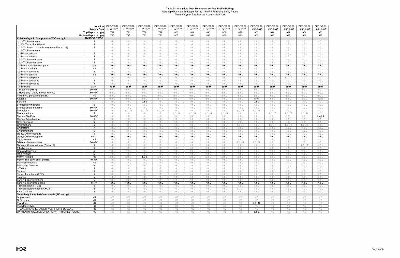
Table 3-1 Analytical Data Summary - Vertical Profile Borings
Northrop Grumman Bethpage Facility / NWIRP Feasibility Study Report
Town of Oyster Bay, Nassau County, New York
Volatile Organic Compounds (VOCs) - ug/L NYSDEC GWQS
1,1,1-Trichloroethane 5
1,1,2,2-Tetrachloroethane 5
1,1,2-Trichloro-1,2,2-trifluoroethane (Freon 113) 5
1,1,2-Trichloroethane 1
1,1-Dichloroethane 5
1,1-Dichloroethene 5
1,2,3-Trichlorobenzene 5
1,2,4-Trichlorobenzene 5
1,2-Dibromo-3-chloropropane 0.04
1,2-Dibromoethane NS
1,2-Dichlorobenzene 3
1,2-Dichloroethane 0.6
1,2-Dichloropropane 1
1,3-Dichlorobenzene 3
1,4-Dichlorobenzene 3
1,4-Dioxane 0.35 *
2-Butanone (MEK) 50 (GV)
2-Hexanone (Methyl n-butyl ketone) 50 (GV)
4-Methyl-2-pentanone (MIBK) NS
Acetone 50 (GV)
Benzene 1
Bromochloromethane 5
Bromodichloromethane 50 (GV)
Bromoform 50 (GV)
Bromomethane 5
Carbon Disulfide 60 (GV)
Carbon Tetrachloride 5
Chlorobenzene 5
Chloroethane 5
Chloroform 7
Chloromethane 5
cis-1,2-Dichloroethene 5
cis-1,3-Dichloropropene 0.4 **
Cyclohexane NS
Dibromochloromethane 50 (GV)
Dichlorodifluoromethane (Freon 12) 5
Ethylbenzene 5
Isopropylbenzene 5
m&p-Xylenes 5
Methyl Acetate NS
Methyl Tert Butyl Ether (MTBE) 10 (GV)
Methylcyclohexane NS
Methylene Chloride 5
o-Xylene 5
Styrene 5
Tetrachloroethene (PCE) 5
Toluene 5
trans-1,2-Dichloroethene 5
trans-1,3-Dichloropropene 0.4 **
Trichloroethene (TCE) 5
Trichlorofluoromethane (CFC-11) 5
Vinyl Chloride 2
Tentatively Identified Compounds (TICs) - ug/L
Isopropanol NS
N-Eicosane NS
Propylene NS
Propylene Glycol NS
TRANS,TRANS-1,6-DIMETHYLSPIRO[4.5]DECANE NS
UNKNOWN VOLATILE ORGANIC WITH HIGHEST CONC. NS
Location
Sample Date
Top Depth (ft bgs)
Bottom Depth (ft bgs)
DEC-VPB2 DEC-VPB2 DEC-VPB2 DEC-VPB2 DEC-VPB2 DEC-VPB2 DEC-VPB2 DEC-VPB2 DEC-VPB2 DEC-VPB2 DEC-VPB2 DEC-VPB2 DEC-VPB2 DEC-VPB2
11/6/2017 11/7/2017 11/7/2017 11/7/2017 11/8/2017 11/8/2017 11/9/2017 11/9/2017 11/9/2017 11/10/2017 11/13/2017 11/13/2017 11/13/2017 11/21/2017
718 743 758 778 803 818 843 858 878 903 918 938 958 983
720 745 760 780 805 820 845 860 880 905 920 940 960 985
1.0 U 1.0 U 1.0 U 1.0 U 1.0 U 1.0 U 1.0 U 1.0 U 1.0 U 1.0 U 1.0 U 1.0 U 1.0 U 1.0 U
1.0 U 1.0 U 1.0 U 1.0 U 1.0 U 1.0 U 1.0 U 1.0 U 1.0 U 1.0 U 1.0 U 1.0 U 1.0 U 1.0 U
1.0 U 1.0 U 1.0 U 1.0 U 1.0 U 1.0 U 1.0 U 1.0 U 1.0 U 1.0 U 1.0 U 1.0 U 1.0 U 1.0 U
1.0 U 1.0 U 1.0 U 1.0 U 1.0 U 1.0 U 1.0 U 1.0 U 1.0 U 1.0 U 1.0 U 1.0 U 1.0 U 1.0 U
1.0 U 1.0 U 1.0 U 1.0 U 1.0 U 1.0 U 1.0 U 1.0 U 1.0 U 1.0 U 1.0 U 1.0 U 1.0 U 1.0 U
1.0 U 1.0 U 1.0 U 1.0 U 1.0 U 1.0 U 1.0 U 1.0 U 1.0 U 1.0 U 1.0 U 1.0 U 1.0 U 1.0 U
1.0 U 1.0 U 1.0 U 1.0 U 1.0 U 1.0 U 1.0 U 1.0 U 1.0 U 1.0 U 1.0 U 1.0 U 1.0 U 1.0 U
1.0 U 1.0 U 1.0 U 1.0 U 1.0 U 1.0 U 1.0 U 1.0 U 1.0 U 1.0 U 1.0 U 1.0 U 1.0 U 1.0 U
1.0 U 1.0 U 1.0 U 1.0 U 1.0 U 1.0 U 1.0 U 1.0 U 1.0 U 1.0 U 1.0 U 1.0 U 1.0 U 1.0 U
1.0 U 1.0 U 1.0 U 1.0 U 1.0 U 1.0 U 1.0 U 1.0 U 1.0 U 1.0 U 1.0 U 1.0 U 1.0 U 1.0 U
1.0 U 1.0 U 1.0 U 1.0 U 1.0 U 1.0 U 1.0 U 1.0 U 1.0 U 1.0 U 1.0 U 1.0 U 1.0 U 1.0 U
1.0 U 1.0 U 1.0 U 1.0 U 1.0 U 1.0 U 1.0 U 1.0 U 1.0 U 1.0 U 1.0 U 1.0 U 1.0 U 1.0 U
1.0 U 1.0 U 1.0 U 1.0 U 1.0 U 1.0 U 1.0 U 1.0 U 1.0 U 1.0 U 1.0 UT 1.0 UT 1.0 U 1.0 U
1.0 U 1.0 U 1.0 U 1.0 U 1.0 U 1.0 U 1.0 U 1.0 U 1.0 U 1.0 U 1.0 U 1.0 U 1.0 U 1.0 U
1.0 U 1.0 U 1.0 U 1.0 U 1.0 U 1.0 U 1.0 U 1.0 U 1.0 U 1.0 U 1.0 U 1.0 U 1.0 U 1.0 U
50 U 50 U 50 U 50 U 50 U 50 U 50 U 50 U 50 U 50 U 50 U 50 U 50 U 50 U
5.0 U 5.0 U 5.0 U 5.0 U 5.0 U 5.0 U 5.0 U 5.0 U 5.0 U 5.0 U 5.0 U 5.0 U 5.0 U 5.0 U
5.0 U 5.0 U 5.0 U 5.0 U 5.0 U 5.0 U 5.0 U 5.0 U 5.0 U 5.0 U 5.0 U 5.0 U 5.0 U 5.0 U
5.0 U 5.0 U 5.0 U 5.0 U 5.0 U 5.0 U 5.0 U 5.0 U 5.0 U 5.0 U 5.0 U 5.0 U 5.0 U 5.0 U
6.5 U 5.0 U 9.4 U 5.1 U 5.0 U 5.0 U 8.0 U 7.5 U 5.0 U 10 U 9.2 U 5.3 U 5.0 U 12 U
1.0 U 1.0 U 0.1 J 1.0 U 1.0 U 1.0 U 1.0 U 1.0 U 1.0 U 0.1 J 1.0 U 1.0 U 1.0 U 1.0 U
1.0 U 1.0 U 1.0 U 1.0 U 1.0 U 1.0 U 1.0 U 1.0 U 1.0 U 1.0 U 1.0 U 1.0 U 1.0 U 1.0 U
1.0 U 1.0 U 1.0 U 1.0 U 1.0 U 1.0 U 1.0 U 1.0 U 1.0 U 1.0 U 1.0 U 1.0 U 1.0 U 1.0 U
1.0 U 1.0 UJ 1.0 UJ 1.0 UJ 1.0 U 1.0 U 1.0 U 1.0 U 1.0 UJ 1.0 UJ 1.0 U 1.0 U 1.0 U 1.0 U
1.0 U 1.0 U 1.0 U 1.0 U 1.0 UJ 1.0 UJ 1.0 UJ 1.0 UJ 1.0 U 1.0 U 1.0 UT 1.0 UT 1.0 UJ 1.0 U
1.0 U 1.0 U 1.0 U 1.0 U 1.0 U 1.0 U 1.0 U 1.0 U 1.0 U 1.0 U 1.0 U 1.0 U 1.0 U 0.46 J
1.0 U 1.0 U 1.0 U 1.0 U 1.0 U 1.0 U 1.0 U 1.0 U 1.0 U 1.0 U 1.0 U 1.0 U 1.0 U 1.0 U
1.0 U 1.0 U 1.0 U 1.0 U 1.0 U 1.0 U 1.0 U 1.0 U 1.0 U 1.0 U 1.0 U 1.0 U 1.0 U 1.0 U
1.0 U 1.0 U 1.0 U 1.0 U 1.0 U 1.0 U 1.0 U 1.0 U 1.0 UT 1.0 U 1.0 UT 1.0 UT 1.0 UT 1.0 U
1.0 U 1.0 U 1.0 U 1.0 U 1.0 U 1.0 U 1.0 U 1.0 U 1.0 U 1.0 U 1.0 U 1.0 U 1.0 U 1.0 U
1.0 U 1.0 U 1.0 U 1.0 U 1.0 U 1.0 U 1.0 U 1.0 U 1.0 U 1.0 U 1.0 U 1.0 U 1.0 U 1.0 U
1.0 U 1.0 U 1.0 U 1.0 U 1.0 U 1.0 U 1.0 U 1.0 U 1.0 U 1.0 U 1.0 U 1.0 U 1.0 U 1.0 U
1.0 U 1.0 U 1.0 U 1.0 U 1.0 U 1.0 U 1.0 U 1.0 U 1.0 U 1.0 U 1.0 U 1.0 U 1.0 U 1.0 U
1.0 U 1.0 U 1.0 U 1.0 U 1.0 U 1.0 U 1.0 U 1.0 U 1.0 U 1.0 U 1.0 U 1.0 U 1.0 U 1.0 U
1.0 U 1.0 U 1.0 U 1.0 U 1.0 U 1.0 U 1.0 U 1.0 U 1.0 UJ 1.0 UJ 1.0 U 1.0 U 1.0 U 1.0 U
1.0 U 1.0 U 1.0 U 1.0 U 1.0 U 1.0 U 1.0 U 1.0 U 1.0 U 1.0 U 1.0 U 1.0 U 1.0 UT 1.0 U
1.0 U 1.0 U 1.0 U 1.0 U 1.0 U 1.0 U 1.0 U 1.0 U 1.0 U 1.0 U 1.0 U 1.0 U 1.0 U 1.0 U
1.0 U 1.0 U 1.0 U 1.0 U 1.0 U 1.0 U 1.0 U 1.0 U 1.0 U 1.0 U 1.0 U 1.0 U 1.0 U 1.0 U
1.0 U 1.0 U 1.0 U 1.0 U 1.0 U 1.0 U 1.0 U 1.0 U 1.0 U 1.0 U 1.0 U 1.0 U 1.0 U 1.0 U
5.0 U 5.0 U 1.6 J 5.0 U 5.0 U 5.0 U 5.0 U 5.0 U 5.0 U 5.0 U 5.0 U 5.0 U 5.0 U 5.0 U
1.0 U 1.0 U 1.0 U 1.0 U 1.0 U 1.0 U 1.0 U 1.0 U 1.0 U 1.0 U 1.0 U 1.0 U 1.0 U 1.0 U
1.0 U 1.0 U 1.0 U 1.0 U 1.0 U 1.0 U 1.0 U 1.0 U 1.0 U 1.0 U 1.0 U 1.0 U 1.0 U 1.0 U
1.0 U 1.0 U 1.0 U 1.0 U 1.0 U 1.0 U 1.0 U 1.0 U 1.0 U 1.0 U 1.0 U 1.0 U 1.0 U 1.0 U
1.0 U 1.0 U 1.0 U 1.0 U 1.0 U 1.0 U 1.0 U 1.0 U 1.0 U 1.0 U 1.0 U 1.0 U 1.0 U 1.0 U
1.0 U 1.0 U 1.0 U 1.0 U 1.0 U 1.0 U 1.0 U 1.0 U 1.0 U 1.0 U 1.0 U 1.0 U 1.0 U 1.0 U
1.0 U 1.0 U 1.0 U 1.0 U 1.0 U 1.0 U 1.0 U 1.0 U 1.0 U 1.0 U 1.0 U 1.0 U 1.0 U 1.0 U
1.0 U 1.0 U 1.0 U 1.0 U 1.0 U 1.0 U 1.0 U 1.0 U 1.0 U 1.0 U 1.0 U 1.0 U 1.0 U 1.0 U
1.0 U 1.0 U 1.0 U 1.0 U 1.0 U 1.0 U 1.0 U 1.0 U 1.0 U 1.0 U 1.0 U 1.0 U 1.0 U 1.0 U
1.0 U 1.0 U 1.0 U 1.0 U 1.0 U 1.0 U 1.0 U 1.0 U 1.0 U 1.0 U 1.0 U 1.0 U 1.0 U 1.0 U
1.0 U 1.0 U 1.0 U 1.0 U 1.0 U 1.0 U 1.0 U 1.0 U 1.0 U 1.0 U 1.0 U 1.0 U 1.0 U 1.0 U
1.0 U 1.0 U 1.0 U 1.0 U 1.0 U 1.0 U 1.0 U 1.0 U 1.0 UT 1.0 U 1.0 U 1.0 U 1.0 U 1.0 U
1.0 U 1.0 U 1.0 U 1.0 U 1.0 U 1.0 U 1.0 U 1.0 U 1.0 U 1.0 U 1.0 U 1.0 U 1.0 U 1.0 U
ND ND ND ND ND ND ND ND ND ND ND ND ND ND
ND ND ND ND ND ND ND ND ND ND ND ND ND ND
ND ND ND ND ND ND ND ND ND 7.2 JN ND ND ND ND
ND ND ND ND ND ND ND ND ND ND ND ND ND ND
ND ND ND ND ND ND ND ND ND ND ND ND ND ND
ND ND ND ND ND ND ND ND ND 5.1 J ND ND ND ND
Page 5 of 6
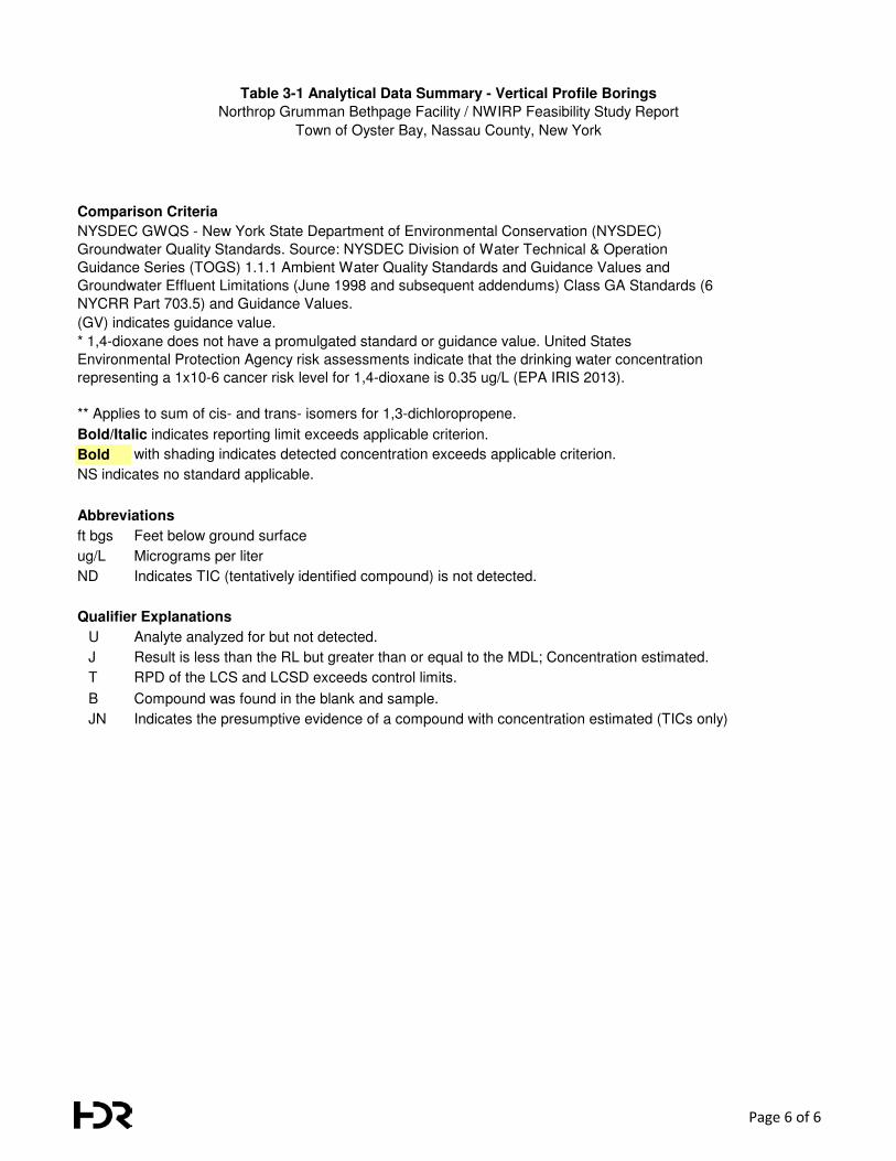
Table 3-1 Analytical Data Summary - Vertical Profile Borings
Northrop Grumman Bethpage Facility / NWIRP Feasibility Study Report
Town of Oyster Bay, Nassau County, New York
Comparison Criteria
Bold with shading indicates detected concentration exceeds applicable criterion.
Abbreviations
ft bgs Feet below ground surface
ug/L Micrograms per liter
ND Indicates TIC (tentatively identified compound) is not detected.
Qualifier Explanations
U Analyte analyzed for but not detected.
J Result is less than the RL but greater than or equal to the MDL; Concentration estimated.
T RPD of the LCS and LCSD exceeds control limits.
B Compound was found in the blank and sample.
JN Indicates the presumptive evidence of a compound with concentration estimated (TICs only)
NS indicates no standard applicable.
NYSDEC GWQS - New York State Department of Environmental Conservation (NYSDEC)
Groundwater Quality Standards. Source: NYSDEC Division of Water Technical & Operation
Guidance Series (TOGS) 1.1.1 Ambient Water Quality Standards and Guidance Values and
Groundwater Effluent Limitations (June 1998 and subsequent addendums) Class GA Standards (6
NYCRR Part 703.5) and Guidance Values.
(GV) indicates guidance value.
* 1,4-dioxane does not have a promulgated standard or guidance value. United States
Environmental Protection Agency risk assessments indicate that the drinking water concentration
representing a 1x10⁻⁶ cancer risk level for 1,4-dioxane is 0.35 ug/L (EPA IRIS 2013).
** Applies to sum of cis- and trans- isomers for 1,3-dichloropropene.
Bold/Italic indicates reporting limit exceeds applicable criterion.
Page 6 of 6
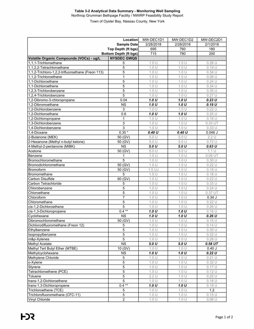
Table 3-2 Analytical Data Summary - Monitoring Well SamplingNorthrop Grumman Bethpage Facility / NWIRP Feasibility Study Report
Town of Oyster Bay, Nassau County, New York
MW-DEC1D1 MW-DEC1D2 MW-DEC2D12/28/2018 2/28/2018 2/1/2018
695 760 180715 780 200
Volatile Organic Compounds (VOCs) - ug/L NYSDEC GWQS1,1,1-Trichloroethane 5 1.0 U 1.0 U 0.28 U1,1,2,2-Tetrachloroethane 5 1.0 U 1.0 U 0.19 U1,1,2-Trichloro-1,2,2-trifluoroethane (Freon 113) 5 1.0 U 1.0 U 0.34 U1,1,2-Trichloroethane 1 1.0 U 1.0 U 0.08 U1,1-Dichloroethane 5 1.0 U 1.0 U 0.24 U1,1-Dichloroethene 5 1.0 U 1.0 U 0.34 U1,2,3-Trichlorobenzene 5 1.0 U 1.0 U 0.35 U1,2,4-Trichlorobenzene 5 1.0 U 1.0 U 0.27 U1,2-Dibromo-3-chloropropane 0.04 1.0 U 1.0 U 0.23 U
1,2-Dibromoethane NS 1.0 U 1.0 U 0.19 U
1,2-Dichlorobenzene 3 1.0 U 1.0 U 0.22 U1,2-Dichloroethane 0.6 1.0 U 1.0 U 0.25 U1,2-Dichloropropane 1 1.0 U 1.0 U 0.18 U1,3-Dichlorobenzene 3 1.0 U 1.0 U 0.33 UT1,4-Dichlorobenzene 3 1.0 U 1.0 U 0.33 U1,4-Dioxane 0.35 * 0.40 U 0.40 U 0.046 J2-Butanone (MEK) 50 (GV) 5.0 U 5.0 U 2.2 U2-Hexanone (Methyl n-butyl ketone) 50 (GV) 5.0 U 5.0 U 0.72 U4-Methyl-2-pentanone (MIBK) NS 5.0 U 5.0 U 0.63 U
Acetone 50 (GV) 5.0 U 5.0 U 1.1 UBenzene 1 1.0 U 1.0 U 0.09 UTBromochloromethane 5 1.0 U 1.0 U 0.30 UBromodichloromethane 50 (GV) 1.0 U 1.0 U 0.22 UBromoform 50 (GV) 1.0 UJ 1.0 U 0.18 UBromomethane 5 1.0 U 1.0 U 0.18 UCarbon Disulfide 60 (GV) 1.0 U 1.0 U 0.22 UCarbon Tetrachloride 5 1.0 U 1.0 U 0.33 UChlorobenzene 5 1.0 U 1.0 U 0.24 UChloroethane 5 1.0 U 1.0 U 0.37 UTChloroform 7 1.0 U 1.0 U 0.34 JChloromethane 5 1.0 U 1.0 U 0.22 Ucis-1,2-Dichloroethene 5 1.0 U 1.0 U 0.26 Ucis-1,3-Dichloropropene 0.4 ** 1.0 U 1.0 U 0.16 UCyclohexane NS 1.0 U 1.0 U 0.26 U
Dibromochloromethane 50 (GV) 1.0 U 1.0 U 0.15 UDichlorodifluoromethane (Freon 12) 5 1.0 U 1.0 U 0.14 UEthylbenzene 5 1.0 U 1.0 U 0.30 UIsopropylbenzene 5 1.0 U 1.0 U 0.32 Um&p-Xylenes 5 1.0 U 1.0 U 0.28 UMethyl Acetate NS 5.0 U 5.0 U 0.58 UT
Methyl Tert Butyl Ether (MTBE) 10 (GV) 1.0 U 1.0 U 0.40 JMethylcyclohexane NS 1.0 U 1.0 U 0.22 U
Methylene Chloride 5 1.0 U 1.0 U 0.21 Uo-Xylene 5 1.0 U 1.0 U 0.32 UStyrene 5 1.0 U 1.0 U 0.17 UTetrachloroethene (PCE) 5 1.0 U 1.0 U 0.12 UToluene 5 2.2 U 1.0 U 0.25 Utrans-1,2-Dichloroethene 5 1.0 U 1.0 U 0.18 Utrans-1,3-Dichloropropene 0.4 ** 1.0 U 1.0 U 0.19 UTrichloroethene (TCE) 5 1.0 U 1.0 U 1.2Trichlorofluoromethane (CFC-11) 5 1.0 U 1.0 U 0.15 UVinyl Chloride 2 1.0 U 1.0 U 0.06 U
LocationSample Date
Top Depth (ft bgs)Bottom Depth (ft bgs)
Page 1 of 2
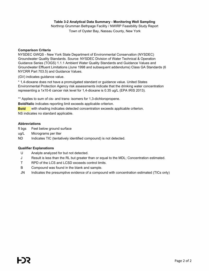
Table 3-2 Analytical Data Summary - Monitoring Well SamplingNorthrop Grumman Bethpage Facility / NWIRP Feasibility Study Report
Town of Oyster Bay, Nassau County, New York
Comparison Criteria
Bold with shading indicates detected concentration exceeds applicable criterion.
Abbreviationsft bgs Feet below ground surfaceug/L Micrograms per literND Indicates TIC (tentatively identified compound) is not detected.
Qualifier ExplanationsU Analyte analyzed for but not detected.J Result is less than the RL but greater than or equal to the MDL; Concentration estimated.T RPD of the LCS and LCSD exceeds control limits.B Compound was found in the blank and sample.JN Indicates the presumptive evidence of a compound with concentration estimated (TICs only)
NYSDEC GWQS - New York State Department of Environmental Conservation (NYSDEC) Groundwater Quality Standards. Source: NYSDEC Division of Water Technical & Operation Guidance Series (TOGS) 1.1.1 Ambient Water Quality Standards and Guidance Values and Groundwater Effluent Limitations (June 1998 and subsequent addendums) Class GA Standards (6 NYCRR Part 703.5) and Guidance Values.
* 1,4-dioxane does not have a promulgated standard or guidance value. United States Environmental Protection Agency risk assessments indicate that the drinking water concentration representing a 1x10⁻⁶ cancer risk level for 1,4-dioxane is 0.35 ug/L (EPA IRIS 2013).
** Applies to sum of cis- and trans- isomers for 1,3-dichloropropene.Bold/Italic indicates reporting limit exceeds applicable criterion.
NS indicates no standard applicable.
(GV) indicates guidance value.
Page 2 of 2
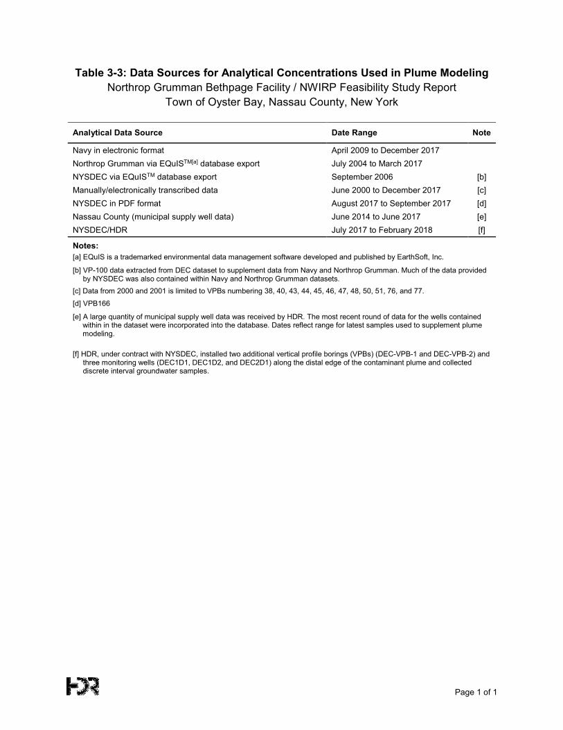
Page 1 of 1
Table 3-3: Data Sources for Analytical Concentrations Used in Plume Modeling Northrop Grumman Bethpage Facility / NWIRP Feasibility Study Report
Town of Oyster Bay, Nassau County, New York
Analytical Data Source Date Range Note
Navy in electronic format April 2009 to December 2017 Northrop Grumman via EQuISTM[a] database export July 2004 to March 2017 NYSDEC via EQuISTM database export September 2006 [b] Manually/electronically transcribed data June 2000 to December 2017 [c] NYSDEC in PDF format August 2017 to September 2017 [d] Nassau County (municipal supply well data) June 2014 to June 2017 [e] NYSDEC/HDR July 2017 to February 2018 [f]
Notes: [a] EQuIS is a trademarked environmental data management software developed and published by EarthSoft, Inc.
[b] VP-100 data extracted from DEC dataset to supplement data from Navy and Northrop Grumman. Much of the data provided by NYSDEC was also contained within Navy and Northrop Grumman datasets.
[c] Data from 2000 and 2001 is limited to VPBs numbering 38, 40, 43, 44, 45, 46, 47, 48, 50, 51, 76, and 77.
[d] VPB166
[e] A large quantity of municipal supply well data was received by HDR. The most recent round of data for the wells contained within in the dataset were incorporated into the database. Dates reflect range for latest samples used to supplement plume modeling.
[f] HDR, under contract with NYSDEC, installed two additional vertical profile borings (VPBs) (DEC-VPB-1 and DEC-VPB-2) and three monitoring wells (DEC1D1, DEC1D2, and DEC2D1) along the distal edge of the contaminant plume and collected discrete interval groundwater samples.
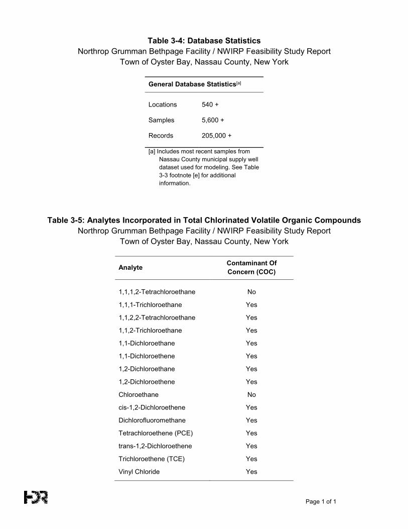
Page 1 of 1
Table 3-4: Database Statistics Northrop Grumman Bethpage Facility / NWIRP Feasibility Study Report
Town of Oyster Bay, Nassau County, New York
General Database Statistics[a]
Locations 540 +
Samples 5,600 +
Records 205,000 +
[a] Includes most recent samples from Nassau County municipal supply well dataset used for modeling. See Table 3-3 footnote [e] for additional information.
Table 3-5: Analytes Incorporated in Total Chlorinated Volatile Organic Compounds Northrop Grumman Bethpage Facility / NWIRP Feasibility Study Report
Town of Oyster Bay, Nassau County, New York
Analyte Contaminant Of Concern (COC)
1,1,1,2-Tetrachloroethane No
1,1,1-Trichloroethane Yes
1,1,2,2-Tetrachloroethane Yes
1,1,2-Trichloroethane Yes
1,1-Dichloroethane Yes
1,1-Dichloroethene Yes
1,2-Dichloroethane Yes
1,2-Dichloroethene Yes
Chloroethane No
cis-1,2-Dichloroethene Yes
Dichlorofluoromethane Yes
Tetrachloroethene (PCE) Yes
trans-1,2-Dichloroethene Yes
Trichloroethene (TCE) Yes
Vinyl Chloride Yes
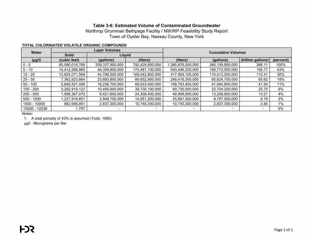
Table 3-6: Estimated Volume of Contaminated GroundwaterNorthrop Grumman Bethpage Facility / NWIRP Feasibility Study Report
Town of Oyster Bay, Nassau County, New York
TOTAL CHLORINATED VOLATILE ORGANIC COMPOUNDS
Solid(µg/l) (cubic feet) (gallons) (liters) (liters) (gallons) (billion gallons) (percent)
0 - 5 65,080,016,769 209,337,900,000 792,429,800,000 1,385,876,000,000 366,109,900,000 366.11 100% 5 - 10 14,412,268,960 46,358,800,000 175,487,100,000 593,446,200,000 156,772,000,000 156.77 43% 10 - 25 13,924,071,569 44,788,500,000 169,542,800,000 417,959,100,000 110,413,200,000 110.41 30% 25 - 50 7,362,923,864 23,683,800,000 89,652,900,000 248,416,300,000 65,624,700,000 65.62 18% 50 - 100 5,669,501,456 18,236,700,000 69,033,400,000 158,763,400,000 41,940,900,000 41.94 11% 100 - 200 3,262,919,123 10,495,600,000 39,730,100,000 89,730,000,000 23,704,200,000 23.70 6% 200 - 500 1,996,367,070 6,421,600,000 24,308,400,000 49,999,900,000 13,208,600,000 13.21 4% 500 - 1000 1,227,916,601 3,949,700,000 14,951,200,000 25,691,500,000 6,787,000,000 6.79 2% 1000 - 10000 882,066,951 2,837,300,000 10,740,300,000 10,740,300,000 2,837,300,000 2.84 1% 10000 - 12238 1,797 - - - - - 0%Notes: 1. A total porosity of 43% is assumed (Todd, 1980) µg/l - Micrograms per liter
Water Cumulative VolumesLayer VolumesLiquid
Page 1 of 1
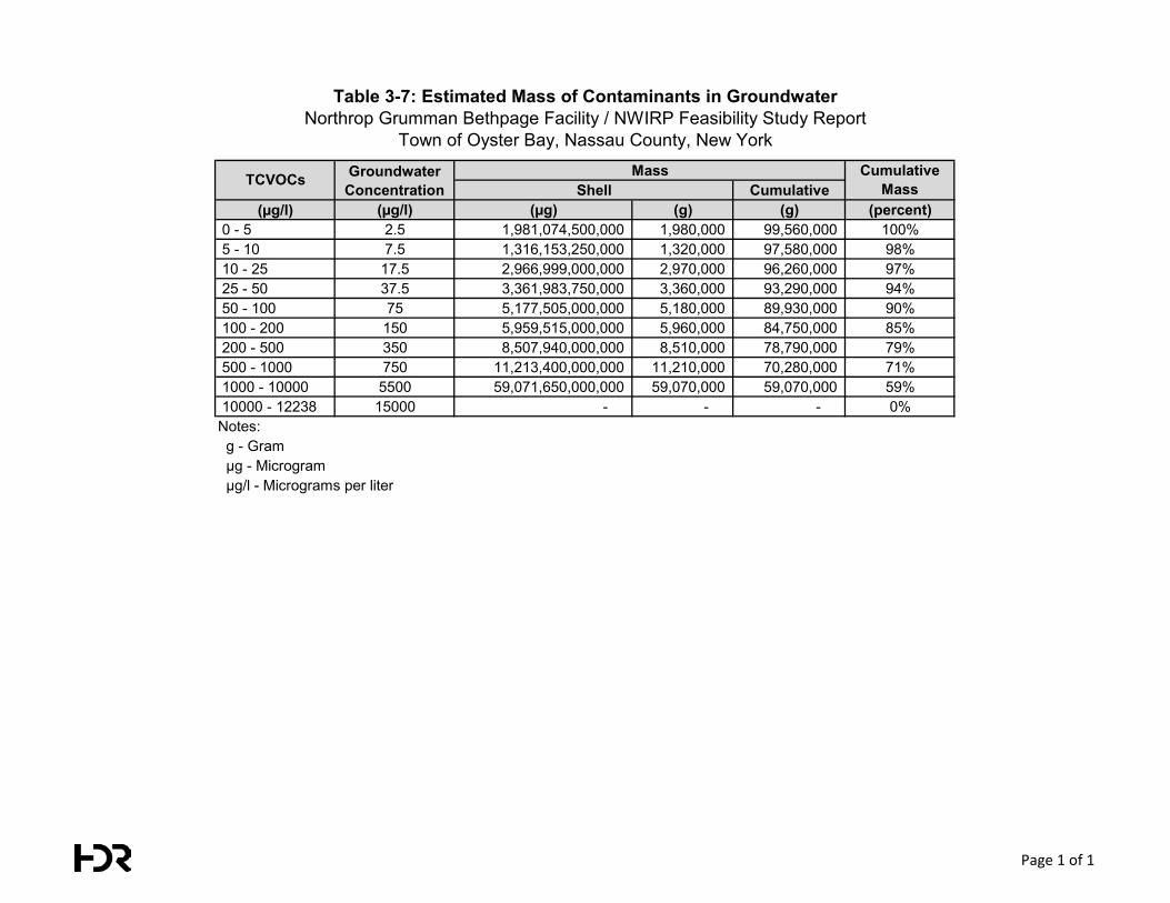
Table 3-7: Estimated Mass of Contaminants in GroundwaterNorthrop Grumman Bethpage Facility / NWIRP Feasibility Study Report
Town of Oyster Bay, Nassau County, New York
Cumulative(µg/l) (µg/l) (µg) (g) (g) (percent)
0 - 5 2.5 1,981,074,500,000 1,980,000 99,560,000 100% 5 - 10 7.5 1,316,153,250,000 1,320,000 97,580,000 98% 10 - 25 17.5 2,966,999,000,000 2,970,000 96,260,000 97% 25 - 50 37.5 3,361,983,750,000 3,360,000 93,290,000 94% 50 - 100 75 5,177,505,000,000 5,180,000 89,930,000 90% 100 - 200 150 5,959,515,000,000 5,960,000 84,750,000 85% 200 - 500 350 8,507,940,000,000 8,510,000 78,790,000 79% 500 - 1000 750 11,213,400,000,000 11,210,000 70,280,000 71% 1000 - 10000 5500 59,071,650,000,000 59,070,000 59,070,000 59% 10000 - 12238 15000 - - - 0%Notes: g - Gram µg - Microgram µg/l - Micrograms per liter
ShellTCVOCs Cumulative
MassGroundwater Concentration
Mass
Page 1 of 1
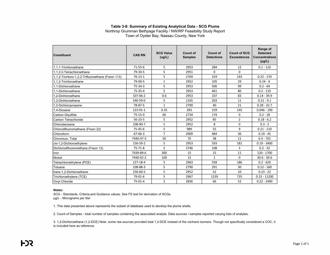
Table 3-8: Summary of Existing Analytical Data - SCG PlumeNorthrop Grumman Bethpage Facility / NWIRP Feasibility Study Report
Town of Oyster Bay, Nassau County, New York
Constituent CAS RN SCG Value(ug/L)
Count of Samples
Count of Detections
Count of SCG Exceedances
Range of Detected
Concentrations(μg/L)
1,1,1-Trichloroethane 71-55-6 5 2953 284 12 0.1 - 110
1,1,2,2-Tetrachloroethane 79-34-5 5 2951 0 0 -
1,1,2-Trichloro-1,2,2-Trifluoroethane (Freon 113) 76-13-1 5 2704 319 143 0.22 - 170
1,1,2-Trichloroethane 79-00-5 1 2952 105 29 0.24 - 4
1,1-Dichloroethane 75-34-3 5 2953 506 99 0.2 - 64
1,1-Dichloroethene 75-35-4 5 2953 461 80 0.2 - 110
1,2-Dichloroethane 107-06-2 0.6 2953 107 83 0.14 - 39.9
1,2-Dichloroethene 540-59-0 5 1165 203 11 0.21 - 9.1
1,2-Dichloropropane 78-87-5 1 2790 40 21 0.28 - 32.7
1,4-Dioxane 123-91-1 0.35 393 159 145 0.046 - 190
Carbon Disulfide 75-15-0 60 2734 174 0 0.2 - 18
Carbon Tetrachloride 56-23-5 5 2952 85 2 0.18 - 6.2
Chlorobenzene 108-90-7 5 2952 8 0 0.3 - 2
Chlorodifluoromethane (Freon 22) 75-45-6 5 989 55 9 0.21 - 110
Chloroform 67-66-3 7 2909 484 36 0.19 - 45
Chromium, Total 7440-47-3 50 70 38 11 0.4 - 701
cis-1,2-Dichloroethylene 156-59-2 5 2953 593 181 0.19 - 3400
Dichlorodifluoromethane (Freon 12) 75-71-8 5 2746 108 3 0.2 - 32
Iron 7439-89-6 300 15 15 11 120 - 1700
Nickel 7440-02-2 100 15 1 0 30.6 - 30.6
Tetrachloroethylene (PCE) 127-18-4 5 2963 558 186 0.2 - 620
Toluene 108-88-3 5 2790 291 30 0.12 - 160
trans-1,2-Dichloroethene 156-60-5 5 2952 52 10 0.23 - 22
Trichloroethylene (TCE) 79-01-6 5 2967 1239 735 0.23 - 11200
Vinyl Chloride 75-01-4 2 2836 66 52 0.22 - 2400
Notes:SCG - Standards, Criteria,and Guidance values. See FS text for derivation of SCGs.μg/L - Micrograms per liter
1. This data presented above represents the subset of database used to develop the plume shells.
2. Count of Samples - total number of samples containing the associated analyte. Data sources / samples reported varying lists of analytes.
3. 1,2-Dichloroethane (1,2-DCE) Note: some raw sources provided total 1,2-DCE instead of the cis/trans isomers. Though not specifically considered a COC, it is included here as reference.
Page 1 of 1
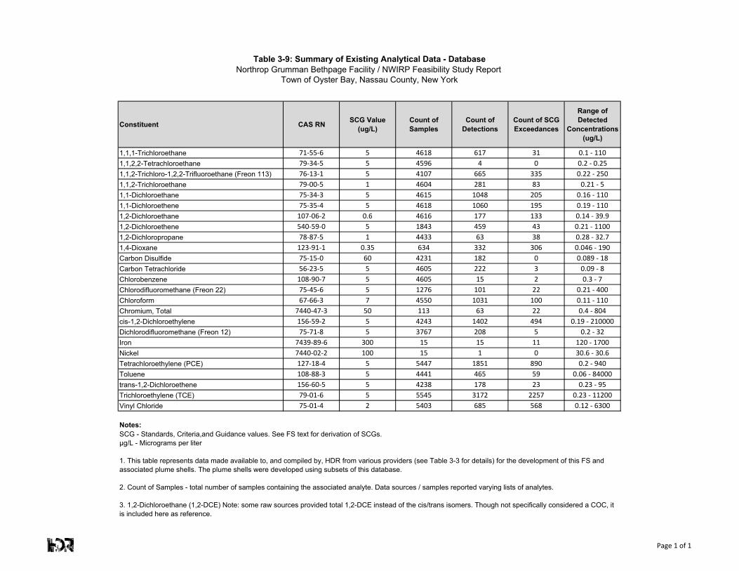
Table 3-9: Summary of Existing Analytical Data - DatabaseNorthrop Grumman Bethpage Facility / NWIRP Feasibility Study Report
Town of Oyster Bay, Nassau County, New York
Constituent CAS RN SCG Value(ug/L)
Count of Samples
Count of Detections
Count of SCG Exceedances
Range of Detected
Concentrations(ug/L)
1,1,1-Trichloroethane 71-55-6 5 4618 617 31 0.1 - 110
1,1,2,2-Tetrachloroethane 79-34-5 5 4596 4 0 0.2 - 0.25
1,1,2-Trichloro-1,2,2-Trifluoroethane (Freon 113) 76-13-1 5 4107 665 335 0.22 - 250
1,1,2-Trichloroethane 79-00-5 1 4604 281 83 0.21 - 5
1,1-Dichloroethane 75-34-3 5 4615 1048 205 0.16 - 110
1,1-Dichloroethene 75-35-4 5 4618 1060 195 0.19 - 110
1,2-Dichloroethane 107-06-2 0.6 4616 177 133 0.14 - 39.9
1,2-Dichloroethene 540-59-0 5 1843 459 43 0.21 - 1100
1,2-Dichloropropane 78-87-5 1 4433 63 38 0.28 - 32.7
1,4-Dioxane 123-91-1 0.35 634 332 306 0.046 - 190
Carbon Disulfide 75-15-0 60 4231 182 0 0.089 - 18
Carbon Tetrachloride 56-23-5 5 4605 222 3 0.09 - 8
Chlorobenzene 108-90-7 5 4605 15 2 0.3 - 7
Chlorodifluoromethane (Freon 22) 75-45-6 5 1276 101 22 0.21 - 400
Chloroform 67-66-3 7 4550 1031 100 0.11 - 110
Chromium, Total 7440-47-3 50 113 63 22 0.4 - 804
cis-1,2-Dichloroethylene 156-59-2 5 4243 1402 494 0.19 - 210000
Dichlorodifluoromethane (Freon 12) 75-71-8 5 3767 208 5 0.2 - 32
Iron 7439-89-6 300 15 15 11 120 - 1700
Nickel 7440-02-2 100 15 1 0 30.6 - 30.6
Tetrachloroethylene (PCE) 127-18-4 5 5447 1851 890 0.2 - 940
Toluene 108-88-3 5 4441 465 59 0.06 - 84000
trans-1,2-Dichloroethene 156-60-5 5 4238 178 23 0.23 - 95
Trichloroethylene (TCE) 79-01-6 5 5545 3172 2257 0.23 - 11200
Vinyl Chloride 75-01-4 2 5403 685 568 0.12 - 6300
Notes:SCG - Standards, Criteria,and Guidance values. See FS text for derivation of SCGs.μg/L - Micrograms per liter
1. This table represents data made available to, and compiled by, HDR from various providers (see Table 3-3 for details) for the development of this FS and associated plume shells. The plume shells were developed using subsets of this database.
2. Count of Samples - total number of samples containing the associated analyte. Data sources / samples reported varying lists of analytes.
3. 1,2-Dichloroethane (1,2-DCE) Note: some raw sources provided total 1,2-DCE instead of the cis/trans isomers. Though not specifically considered a COC, it is included here as reference.
Page 1 of 1
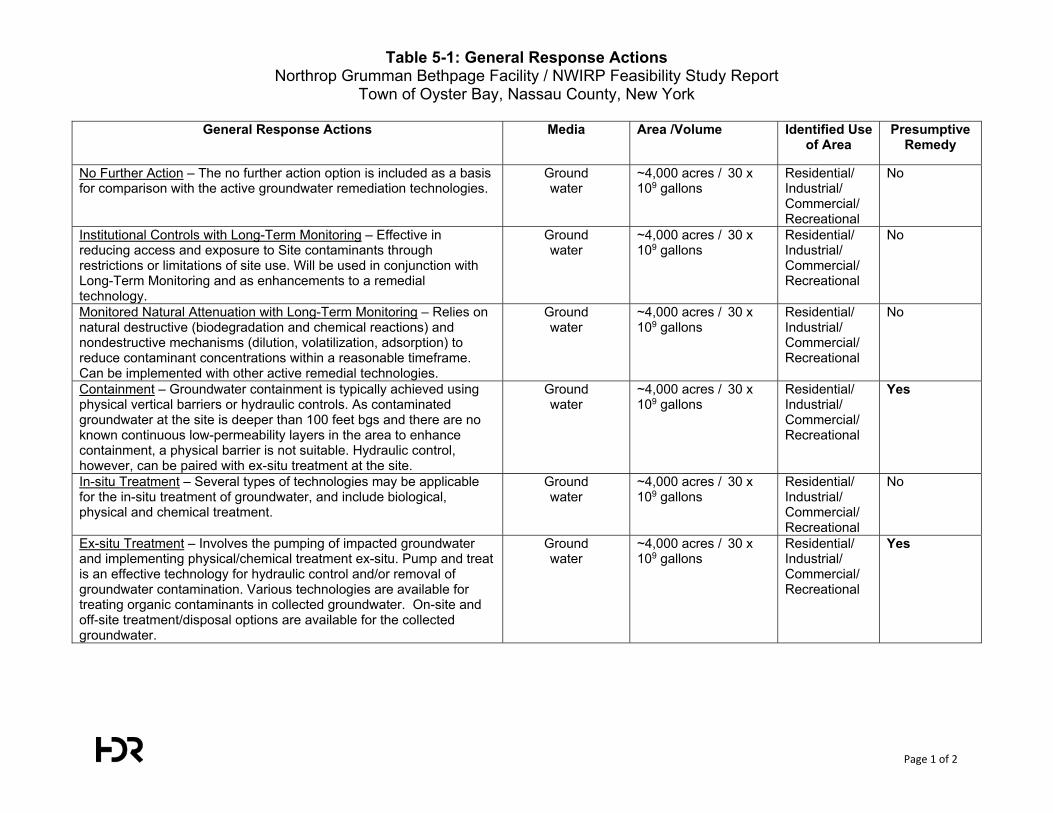
Table 5-1: General Response Actions Northrop Grumman Bethpage Facility / NWIRP Feasibility Study Report
Town of Oyster Bay, Nassau County, New York
Page 1 of 2
General Response Actions Media Area /Volume Identified Use of Area
Presumptive Remedy
No Further Action – The no further action option is included as a basis for comparison with the active groundwater remediation technologies.
Ground water
~4,000 acres / 30 x 109 gallons
Residential/ Industrial/ Commercial/ Recreational
No
Institutional Controls with Long-Term Monitoring – Effective in reducing access and exposure to Site contaminants through restrictions or limitations of site use. Will be used in conjunction with Long-Term Monitoring and as enhancements to a remedial technology.
Ground water
~4,000 acres / 30 x 109 gallons
Residential/ Industrial/ Commercial/ Recreational
No
Monitored Natural Attenuation with Long-Term Monitoring – Relies on natural destructive (biodegradation and chemical reactions) and nondestructive mechanisms (dilution, volatilization, adsorption) to reduce contaminant concentrations within a reasonable timeframe. Can be implemented with other active remedial technologies.
Ground water
~4,000 acres / 30 x 109 gallons
Residential/ Industrial/ Commercial/ Recreational
No
Containment – Groundwater containment is typically achieved using physical vertical barriers or hydraulic controls. As contaminated groundwater at the site is deeper than 100 feet bgs and there are no known continuous low-permeability layers in the area to enhance containment, a physical barrier is not suitable. Hydraulic control, however, can be paired with ex-situ treatment at the site.
Ground water
~4,000 acres / 30 x 109 gallons
Residential/ Industrial/ Commercial/ Recreational
Yes
In-situ Treatment – Several types of technologies may be applicable for the in-situ treatment of groundwater, and include biological, physical and chemical treatment.
Ground water
~4,000 acres / 30 x 109 gallons
Residential/ Industrial/ Commercial/ Recreational
No
Ex-situ Treatment – Involves the pumping of impacted groundwater and implementing physical/chemical treatment ex-situ. Pump and treat is an effective technology for hydraulic control and/or removal of groundwater contamination. Various technologies are available for treating organic contaminants in collected groundwater. On-site and off-site treatment/disposal options are available for the collected groundwater.
Ground water
~4,000 acres / 30 x 109 gallons
Residential/ Industrial/ Commercial/ Recreational
Yes
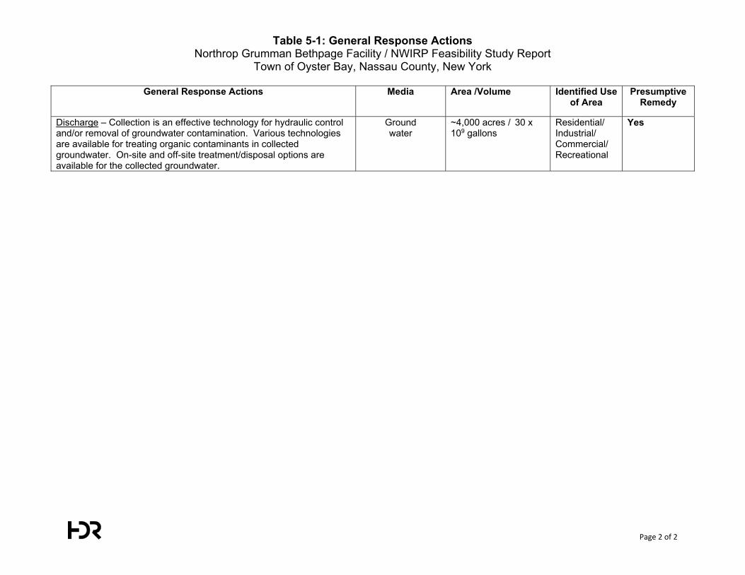
Table 5-1: General Response Actions Northrop Grumman Bethpage Facility / NWIRP Feasibility Study Report
Town of Oyster Bay, Nassau County, New York
Page 2 of 2
General Response Actions Media Area /Volume Identified Use of Area
Presumptive Remedy
Discharge – Collection is an effective technology for hydraulic control and/or removal of groundwater contamination. Various technologies are available for treating organic contaminants in collected groundwater. On-site and off-site treatment/disposal options are available for the collected groundwater.
Ground water
~4,000 acres / 30 x 109 gallons
Residential/ Industrial/ Commercial/ Recreational
Yes
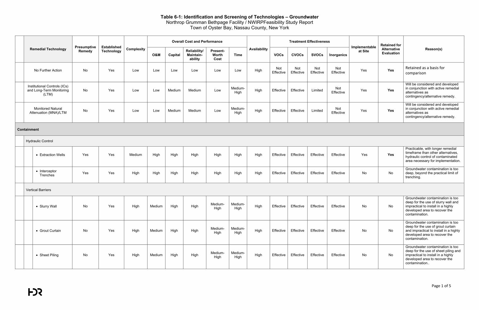
Table 6-1: Identification and Screening of Technologies – Groundwater Northrop Grumman Bethpage Facility / NWIRPFeasibility Study Report
Town of Oyster Bay, Nassau County, New York
Page 1 of 5
Remedial Technology Presumptive Remedy
Established Technology Complexity
Overall Cost and Performance
Availability
Treatment Effectiveness Implementable
at Site Retained for Alternative Evaluation
Reason(s) O&M Capital
Reliability/ Maintain-
ability
Present-Worth Cost
Time VOCs CVOCs SVOCs Inorganics
No Further Action No Yes Low Low Low Low Low Low High Not
Effective Not
Effective Not
Effective Not
Effective Yes Yes Retained as a basis for comparison
Institutional Controls (ICs) and Long-Term Monitoring
(LTM) No Yes Low Low Medium Medium Low Medium-
High High Effective Effective Limited Not Effective Yes Yes
Will be considered and developed in conjunction with active remedial alternatives as contingency/alternative remedy.
Monitored Natural
Attenuation (MNA)/LTM No Yes Low Low Medium Medium Low Medium-High High Effective Effective Limited Not
Effective Yes Yes
Will be considered and developed in conjunction with active remedial alternatives as contingency/alternative remedy.
Containment
Hydraulic Control
Extraction Wells Yes Yes Medium High High High High High High Effective Effective Effective Effective Yes Yes Practicable, with longer remedial timeframe than other alternatives, hydraulic control of contaminated area necessary for implementation.
Interceptor Trenches Yes Yes High High High High High High High Effective Effective Effective Effective No No
Groundwater contamination is too deep, beyond the practical limit of trenching.
Vertical Barriers
Slurry Wall No Yes High Medium High High Medium-High
Medium-High High Effective Effective Effective Effective No No
Groundwater contamination is too deep for the use of slurry wall and impractical to install in a highly developed area to recover the contamination.
Grout Curtain No Yes High Medium High High Medium-High
Medium-High High Effective Effective Effective Effective No No
Groundwater contamination is too deep for the use of grout curtain and impractical to install in a highly developed area to recover the contamination.
Sheet Piling No Yes High Medium High High Medium-High
Medium-High High Effective Effective Effective Effective No No
Groundwater contamination is too deep for the use of sheet piling and impractical to install in a highly developed area to recover the contamination..
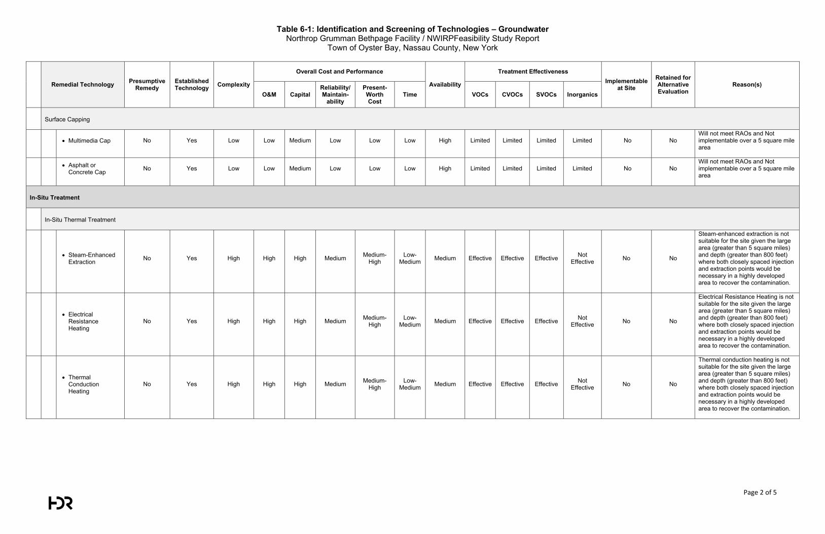
Table 6-1: Identification and Screening of Technologies – Groundwater Northrop Grumman Bethpage Facility / NWIRPFeasibility Study Report
Town of Oyster Bay, Nassau County, New York
Page 2 of 5
Remedial Technology Presumptive Remedy
Established Technology Complexity
Overall Cost and Performance
Availability
Treatment Effectiveness Implementable
at Site Retained for Alternative Evaluation
Reason(s) O&M Capital
Reliability/ Maintain-
ability
Present-Worth Cost
Time VOCs CVOCs SVOCs Inorganics
Surface Capping
Multimedia Cap No Yes Low Low Medium Low Low Low High Limited Limited Limited Limited No No Will not meet RAOs and Not implementable over a 5 square mile area
Asphalt or Concrete Cap No Yes Low Low Medium Low Low Low High Limited Limited Limited Limited No No
Will not meet RAOs and Not implementable over a 5 square mile area
In-Situ Treatment
In-Situ Thermal Treatment
Steam-Enhanced Extraction No Yes High High High Medium Medium-
High Low-
Medium Medium Effective Effective Effective Not Effective No No
Steam-enhanced extraction is not suitable for the site given the large area (greater than 5 square miles) and depth (greater than 800 feet) where both closely spaced injection and extraction points would be necessary in a highly developed area to recover the contamination.
Electrical
Resistance Heating
No Yes High High High Medium Medium-High
Low- Medium Medium Effective Effective Effective Not
Effective No No
Electrical Resistance Heating is not suitable for the site given the large area (greater than 5 square miles) and depth (greater than 800 feet) where both closely spaced injection and extraction points would be necessary in a highly developed area to recover the contamination.
Thermal
Conduction Heating
No Yes High High High Medium Medium-High
Low- Medium Medium Effective Effective Effective Not
Effective No No
Thermal conduction heating is not suitable for the site given the large area (greater than 5 square miles) and depth (greater than 800 feet) where both closely spaced injection and extraction points would be necessary in a highly developed area to recover the contamination.
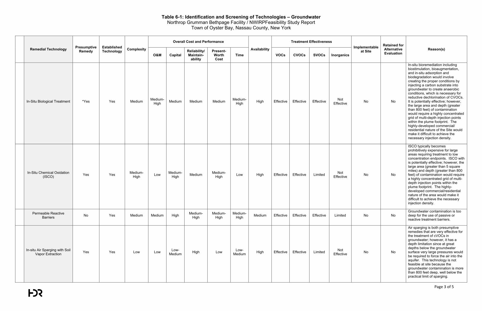
Table 6-1: Identification and Screening of Technologies – Groundwater Northrop Grumman Bethpage Facility / NWIRPFeasibility Study Report
Town of Oyster Bay, Nassau County, New York
Page 3 of 5
Remedial Technology Presumptive Remedy
Established Technology Complexity
Overall Cost and Performance
Availability
Treatment Effectiveness Implementable
at Site Retained for Alternative Evaluation
Reason(s) O&M Capital
Reliability/ Maintain-
ability
Present-Worth Cost
Time VOCs CVOCs SVOCs Inorganics
In-Situ Biological Treatment *Yes Yes Medium Medium-High Medium Medium Medium Medium-
High High Effective Effective Effective Not Effective No No
In-situ bioremediation including biostimulation, bioaugmentation, and in-situ adsorption and biodegradation would involve creating the proper conditions by injecting a carbon substrate into groundwater to create anaerobic conditions, which is necessary for reductive dechlorination of CVOCs. It is potentially effective; however, the large area and depth (greater than 800 feet) of contamination would require a highly concentrated grid of multi-depth injection points within the plume footprint. The highly-developed commercial/ residential nature of the Site would make it difficult to achieve the necessary injection density.
In-Situ Chemical Oxidation (ISCO) Yes Yes Medium-
High Low Medium-High Medium Medium-
High Low High Effective Effective Limited Not Effective No No
ISCO typically becomes prohibitively expensive for large areas requiring treatment to low concentration endpoints. ISCO with is potentially effective; however, the large area (greater than 5 square miles) and depth (greater than 800 feet) of contamination would require a highly concentrated grid of multi-depth injection points within the plume footprint. The highly-developed commercial/residential nature of the area would make it difficult to achieve the necessary injection density.
Permeable Reactive Barriers No Yes Medium Medium High Medium-
High Medium-
High Medium-
High Medium Effective Effective Effective Limited No No Groundwater contamination is too deep for the use of passive or reactive treatment barriers.
In-situ Air Sparging with Soil Vapor Extraction Yes Yes Low Low Low-
Medium High Low Low- Medium High Effective Effective Limited Not
Effective No No
Air sparging is both presumptive remedies that are very effective for the treatment of cVOCs in groundwater; however, it has a depth limitation since at great depths below the groundwater surface very large pressures would be required to force the air into the aquifer. This technology is not feasible at site because the groundwater contamination is more than 800 feet deep, well below the practical limit of sparging.
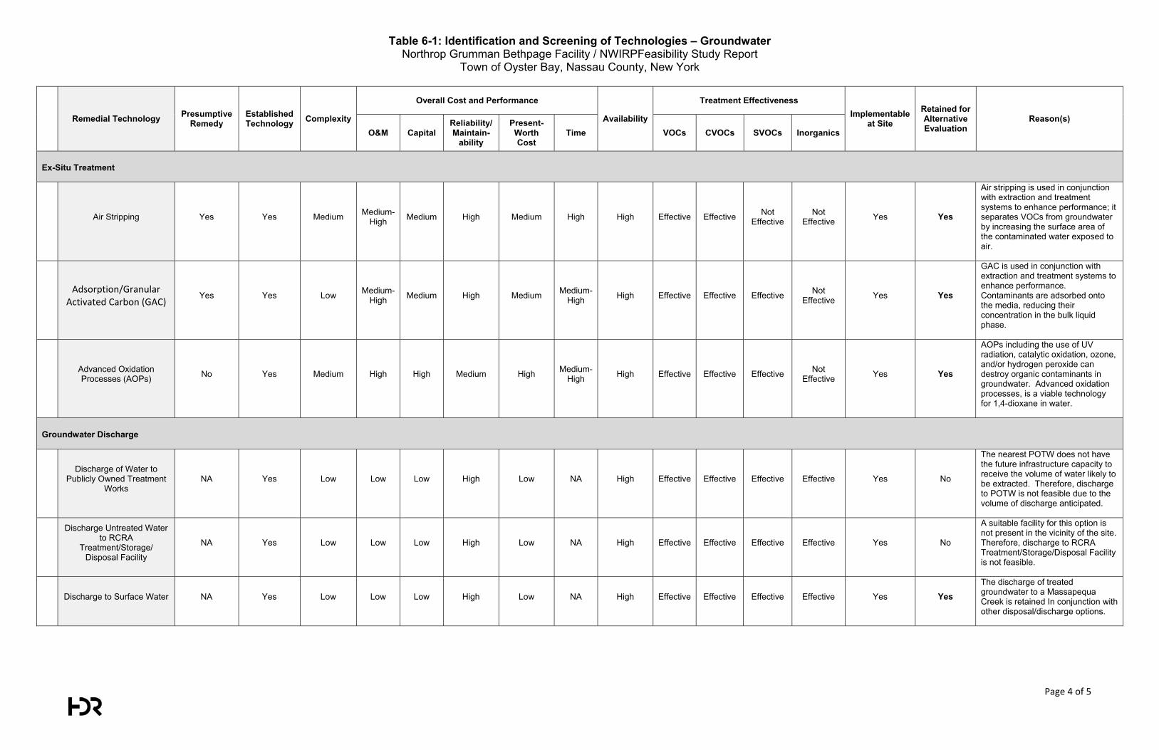
Table 6-1: Identification and Screening of Technologies – Groundwater Northrop Grumman Bethpage Facility / NWIRPFeasibility Study Report
Town of Oyster Bay, Nassau County, New York
Page 4 of 5
Remedial Technology Presumptive Remedy
Established Technology Complexity
Overall Cost and Performance
Availability
Treatment Effectiveness Implementable
at Site Retained for Alternative Evaluation
Reason(s) O&M Capital
Reliability/ Maintain-
ability
Present-Worth Cost
Time VOCs CVOCs SVOCs Inorganics
Ex-Situ Treatment
Air Stripping Yes Yes Medium Medium-High Medium High Medium High High Effective Effective Not
Effective Not
Effective Yes Yes
Air stripping is used in conjunction with extraction and treatment systems to enhance performance; it separates VOCs from groundwater by increasing the surface area of the contaminated water exposed to air.
Adsorption/Granular Activated Carbon (GAC)
Yes Yes Low Medium-High Medium High Medium Medium-
High High Effective Effective Effective Not Effective Yes Yes
GAC is used in conjunction with extraction and treatment systems to enhance performance. Contaminants are adsorbed onto the media, reducing their concentration in the bulk liquid phase.
Advanced Oxidation Processes (AOPs) No Yes Medium High High Medium High Medium-
High High Effective Effective Effective Not Effective Yes Yes
AOPs including the use of UV radiation, catalytic oxidation, ozone, and/or hydrogen peroxide can destroy organic contaminants in groundwater. Advanced oxidation processes, is a viable technology for 1,4-dioxane in water.
Groundwater Discharge
Discharge of Water to Publicly Owned Treatment
Works NA Yes Low Low Low High Low NA High Effective Effective Effective Effective Yes No
The nearest POTW does not have the future infrastructure capacity to receive the volume of water likely to be extracted. Therefore, discharge to POTW is not feasible due to the volume of discharge anticipated.
Discharge Untreated Water to RCRA
Treatment/Storage/ Disposal Facility
NA Yes Low Low Low High Low NA High Effective Effective Effective Effective Yes No
A suitable facility for this option is not present in the vicinity of the site. Therefore, discharge to RCRA Treatment/Storage/Disposal Facility is not feasible.
Discharge to Surface Water NA Yes Low Low Low High Low NA High Effective Effective Effective Effective Yes Yes The discharge of treated groundwater to a Massapequa Creek is retained In conjunction with other disposal/discharge options.
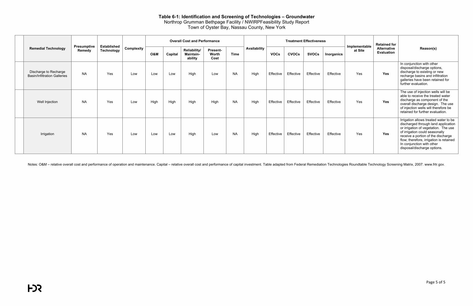
Table 6-1: Identification and Screening of Technologies – Groundwater Northrop Grumman Bethpage Facility / NWIRPFeasibility Study Report
Town of Oyster Bay, Nassau County, New York
Page 5 of 5
Remedial Technology Presumptive Remedy
Established Technology Complexity
Overall Cost and Performance
Availability
Treatment Effectiveness Implementable
at Site Retained for Alternative Evaluation
Reason(s) O&M Capital
Reliability/ Maintain-
ability
Present-Worth Cost
Time VOCs CVOCs SVOCs Inorganics
Discharge to Recharge Basin/Infiltration Galleries NA Yes Low Low Low High Low NA High Effective Effective Effective Effective Yes Yes
In conjunction with other disposal/discharge options, discharge to existing or new recharge basins and infiltration galleries have been retained for further evaluation.
Well Injection NA Yes Low High High High High NA High Effective Effective Effective Effective Yes Yes
The use of injection wells will be able to receive the treated water discharge as component of the overall discharge design. The use of injection wells will therefore be retained for further evaluation.
Irrigation NA Yes Low Low Low High Low NA High Effective Effective Effective Effective Yes Yes
Irrigation allows treated water to be discharged through land application or irrigation of vegetation. The use of irrigation could seasonally receive a portion of the discharge flow; therefore, irrigation is retained In conjunction with other disposal/discharge options.
Notes: O&M – relative overall cost and performance of operation and maintenance. Capital – relative overall cost and performance of capital investment. Table adapted from Federal Remediation Technologies Roundtable Technology Screening Matrix, 2007. www.frtr.gov.
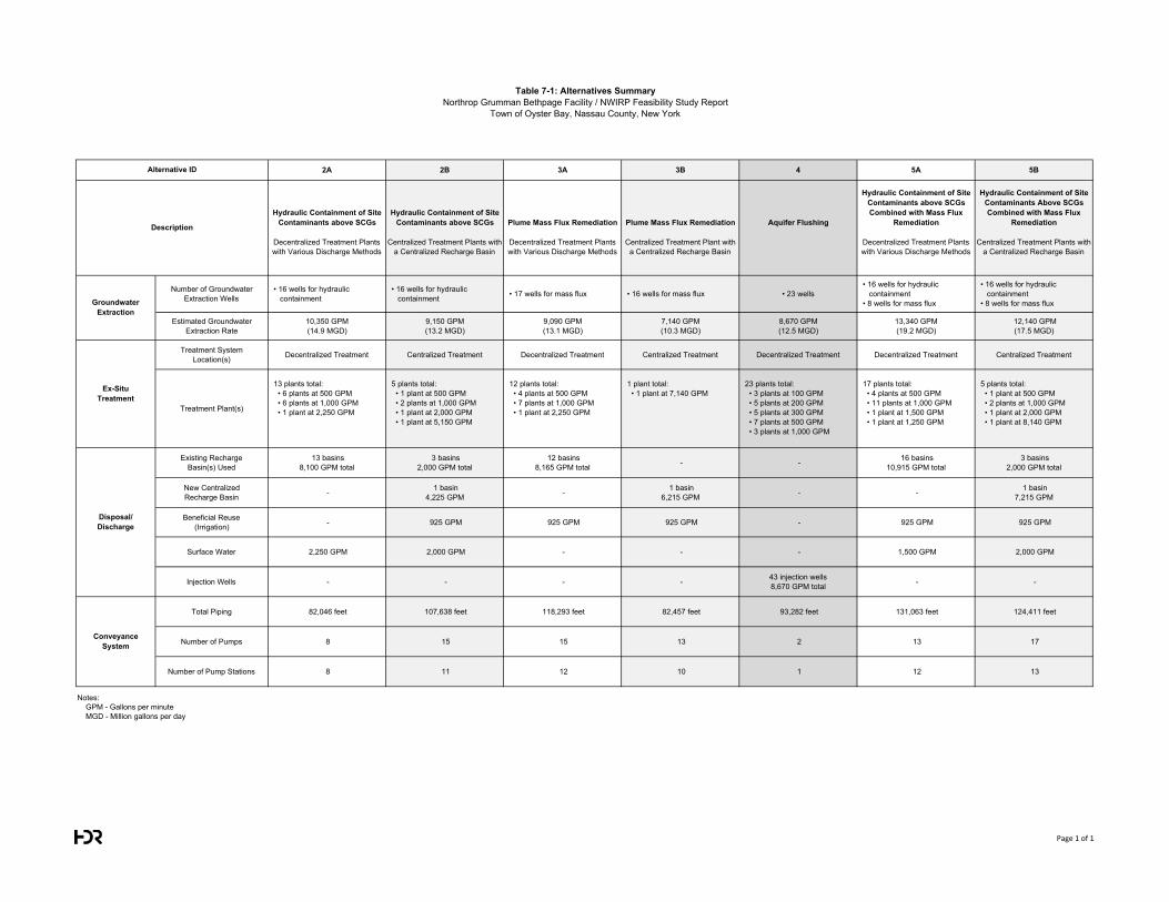
Table 7-1: Alternatives SummaryNorthrop Grumman Bethpage Facility / NWIRP Feasibility Study Report
Town of Oyster Bay, Nassau County, New York
2A 2B 3A 3B 4 5A 5B
Hydraulic Containment of Site Contaminants above SCGs
Hydraulic Containment of Site Contaminants above SCGs Plume Mass Flux Remediation Plume Mass Flux Remediation Aquifer Flushing
Hydraulic Containment of Site Contaminants above SCGs Combined with Mass Flux
Remediation
Hydraulic Containment of Site Contaminants Above SCGs Combined with Mass Flux
Remediation
Decentralized Treatment Plants with Various Discharge Methods
Centralized Treatment Plants with a Centralized Recharge Basin
Decentralized Treatment Plants with Various Discharge Methods
Centralized Treatment Plant with a Centralized Recharge Basin
Decentralized Treatment Plants with Various Discharge Methods
Centralized Treatment Plants with a Centralized Recharge Basin
Number of Groundwater Extraction Wells
• 16 wells for hydraulic containment
• 16 wells for hydraulic containment • 17 wells for mass flux • 16 wells for mass flux • 23 wells
• 16 wells for hydraulic containment • 8 wells for mass flux
• 16 wells for hydraulic containment • 8 wells for mass flux
Estimated Groundwater Extraction Rate
10,350 GPM(14.9 MGD)
9,150 GPM(13.2 MGD)
9,090 GPM(13.1 MGD)
7,140 GPM(10.3 MGD)
8,670 GPM(12.5 MGD)
13,340 GPM(19.2 MGD)
12,140 GPM(17.5 MGD)
Treatment System Location(s) Decentralized Treatment Centralized Treatment Decentralized Treatment Centralized Treatment Decentralized Treatment Decentralized Treatment Centralized Treatment
Treatment Plant(s)
13 plants total: • 6 plants at 500 GPM • 6 plants at 1,000 GPM • 1 plant at 2,250 GPM
5 plants total: • 1 plant at 500 GPM • 2 plants at 1,000 GPM • 1 plant at 2,000 GPM • 1 plant at 5,150 GPM
12 plants total: • 4 plants at 500 GPM • 7 plants at 1,000 GPM • 1 plant at 2,250 GPM
1 plant total: • 1 plant at 7,140 GPM
23 plants total: • 3 plants at 100 GPM • 5 plants at 200 GPM • 5 plants at 300 GPM • 7 plants at 500 GPM • 3 plants at 1,000 GPM
17 plants total: • 4 plants at 500 GPM • 11 plants at 1,000 GPM • 1 plant at 1,500 GPM • 1 plant at 1,250 GPM
5 plants total: • 1 plant at 500 GPM • 2 plants at 1,000 GPM • 1 plant at 2,000 GPM • 1 plant at 8,140 GPM
Existing RechargeBasin(s) Used
13 basins8,100 GPM total
3 basins2,000 GPM total
12 basins8,165 GPM total - - 16 basins
10,915 GPM total 3 basins
2,000 GPM total
New Centralized Recharge Basin - 1 basin
4,225 GPM - 1 basin6,215 GPM - - 1 basin
7,215 GPM
Beneficial Reuse(Irrigation) - 925 GPM 925 GPM 925 GPM - 925 GPM 925 GPM
Surface Water 2,250 GPM 2,000 GPM - - - 1,500 GPM 2,000 GPM
Injection Wells - - - - 43 injection wells8,670 GPM total - -
Total Piping 82,046 feet 107,638 feet 118,293 feet 82,457 feet 93,282 feet 131,063 feet 124,411 feet
Number of Pumps 8 15 15 13 2 13 17
Number of Pump Stations 8 11 12 10 1 12 13
Notes: GPM - Gallons per minute MGD - Million gallons per day
ConveyanceSystem
Description
Alternative ID
Groundwater Extraction
Ex-Situ Treatment
Disposal/ Discharge
Page 1 of 1
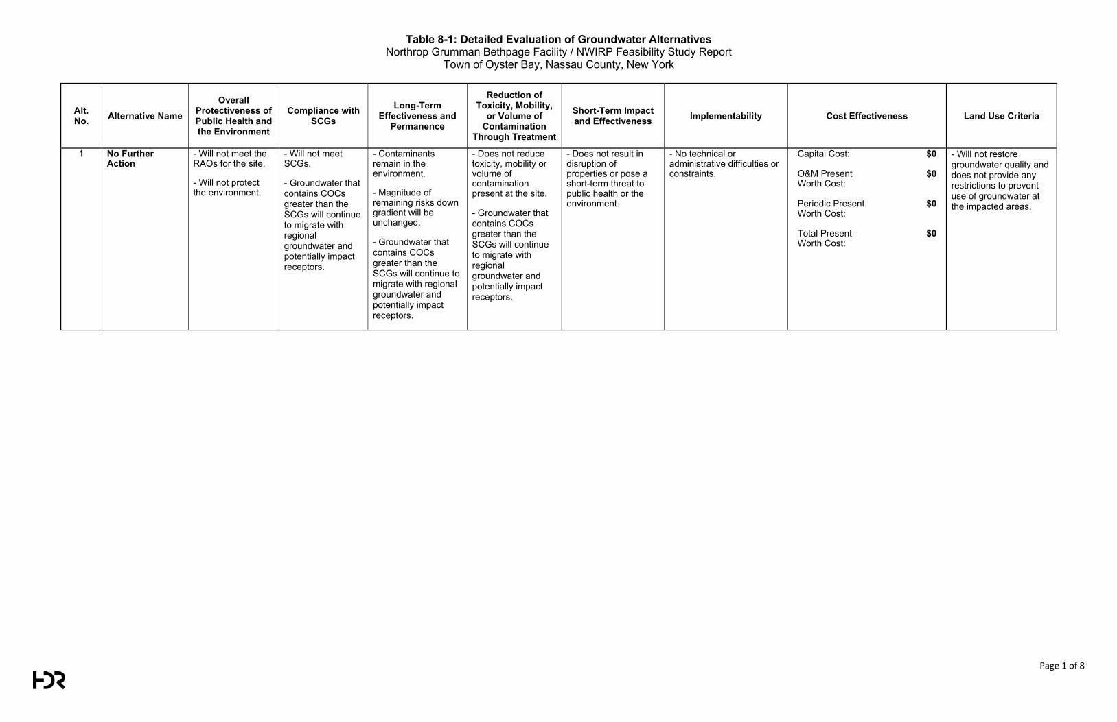
Table 8-1: Detailed Evaluation of Groundwater Alternatives Northrop Grumman Bethpage Facility / NWIRP Feasibility Study Report
Town of Oyster Bay, Nassau County, New York
Page 1 of 8
Alt. No. Alternative Name
Overall Protectiveness of Public Health and the Environment
Compliance with SCGs
Long-Term Effectiveness and
Permanence
Reduction of Toxicity, Mobility,
or Volume of Contamination
Through Treatment
Short-Term Impact and Effectiveness Implementability Cost Effectiveness Land Use Criteria
1 No Further Action
- Will not meet the RAOs for the site.
- Will not protect the environment.
- Will not meet SCGs.
- Groundwater that contains COCs greater than the SCGs will continue to migrate with regional groundwater and potentially impact receptors.
- Contaminants remain in the environment.
- Magnitude of remaining risks down gradient will be unchanged.
- Groundwater that contains COCs greater than the SCGs will continue to migrate with regional groundwater and potentially impact receptors.
- Does not reduce toxicity, mobility or volume of contamination present at the site.
- Groundwater that contains COCs greater than the SCGs will continue to migrate with regional groundwater and potentially impact receptors.
- Does not result in disruption of properties or pose a short-term threat to public health or the environment.
- No technical or administrative difficulties or constraints.
Capital Cost:
$0
O&M Present Worth Cost:
$0
Periodic Present Worth Cost:
$0
Total Present Worth Cost:
$0
- Will not restore groundwater quality and does not provide any restrictions to prevent use of groundwater at the impacted areas.
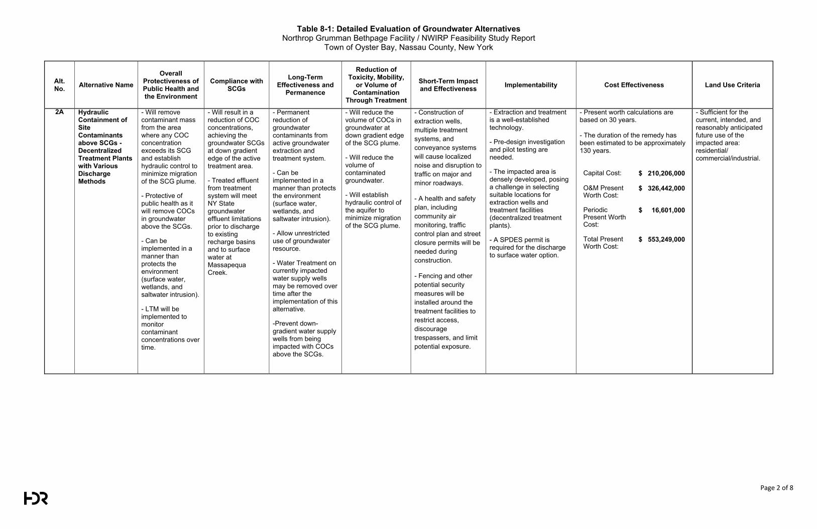
Table 8-1: Detailed Evaluation of Groundwater Alternatives Northrop Grumman Bethpage Facility / NWIRP Feasibility Study Report
Town of Oyster Bay, Nassau County, New York
Page 2 of 8
Alt. No. Alternative Name
Overall Protectiveness of Public Health and the Environment
Compliance with SCGs
Long-Term Effectiveness and
Permanence
Reduction of Toxicity, Mobility,
or Volume of Contamination
Through Treatment
Short-Term Impact and Effectiveness Implementability Cost Effectiveness Land Use Criteria
2A Hydraulic Containment of Site Contaminants above SCGs - Decentralized Treatment Plants with Various Discharge Methods
- Will remove contaminant mass from the area where any COC concentration exceeds its SCG and establish hydraulic control to minimize migration of the SCG plume.
- Protective of public health as it will remove COCs in groundwater above the SCGs.
- Can be implemented in a manner than protects the environment (surface water, wetlands, and saltwater intrusion).
- LTM will be implemented to monitor contaminant concentrations over time.
- Will result in a reduction of COC concentrations, achieving the groundwater SCGs at down gradient edge of the active treatment area.
- Treated effluent from treatment system will meet NY State groundwater effluent limitations prior to discharge to existing recharge basins and to surface water at Massapequa Creek.
- Permanent reduction of groundwater contaminants from active groundwater extraction and treatment system.
- Can be implemented in a manner than protects the environment (surface water, wetlands, and saltwater intrusion).
- Allow unrestricted use of groundwater resource.
- Water Treatment on currently impacted water supply wells may be removed over time after the implementation of this alternative.
-Prevent down-gradient water supply wells from being impacted with COCs above the SCGs.
- Will reduce the volume of COCs in groundwater at down gradient edge of the SCG plume.
- Will reduce the volume of contaminated groundwater.
- Will establish hydraulic control of the aquifer to minimize migration of the SCG plume.
- Construction of extraction wells, multiple treatment systems, and conveyance systems will cause localized noise and disruption to traffic on major and minor roadways.
- A health and safety plan, including community air monitoring, traffic control plan and street closure permits will be needed during construction.
- Fencing and other potential security measures will be installed around the treatment facilities to restrict access, discourage trespassers, and limit potential exposure.
- Extraction and treatment is a well-established technology.
- Pre-design investigation and pilot testing are needed.
- The impacted area is densely developed, posing a challenge in selecting suitable locations for extraction wells and treatment facilities (decentralized treatment plants).
- A SPDES permit is required for the discharge to surface water option.
- Present worth calculations are based on 30 years. - The duration of the remedy has been estimated to be approximately 130 years.
Capital Cost:
$ 210,206,000
O&M Present Worth Cost:
$ 326,442,000
Periodic Present Worth Cost:
$ 16,601,000
Total Present Worth Cost:
$ 553,249,000
- Sufficient for the current, intended, and reasonably anticipated future use of the impacted area: residential/ commercial/industrial.
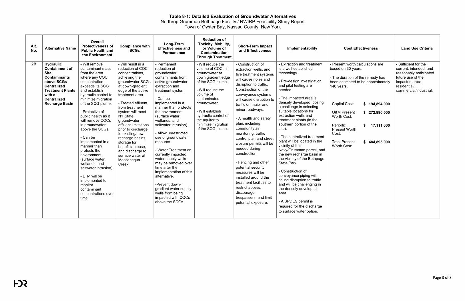
Table 8-1: Detailed Evaluation of Groundwater Alternatives Northrop Grumman Bethpage Facility / NWIRP Feasibility Study Report
Town of Oyster Bay, Nassau County, New York
Page 3 of 8
Alt. No. Alternative Name
Overall Protectiveness of Public Health and the Environment
Compliance with SCGs
Long-Term Effectiveness and
Permanence
Reduction of Toxicity, Mobility,
or Volume of Contamination
Through Treatment
Short-Term Impact and Effectiveness Implementability Cost Effectiveness Land Use Criteria
2B Hydraulic Containment of Site Contaminants above SCGs - Centralized Treatment Plants with a Centralized Recharge Basin
- Will remove contaminant mass from the area where any COC concentration exceeds its SCG and establish hydraulic control to minimize migration of the SCG plume.
- Protective of public health as it will remove COCs in groundwater above the SCGs.
- Can be implemented in a manner than protects the environment (surface water, wetlands, and saltwater intrusion).
- LTM will be implemented to monitor contaminant concentrations over time.
- Will result in a reduction of COC concentrations, achieving the groundwater SCGs at down-gradient edge of the active treatment area.
- Treated effluent from treatment system will meet NY State groundwater effluent limitations prior to discharge to existing/new recharge basins, storage for beneficial reuse, and discharge to surface water at Massapequa Creek.
- Permanent reduction of groundwater contaminants from active groundwater extraction and treatment system.
- Can be implemented in a manner than protects the environment (surface water, wetlands, and saltwater intrusion).
- Allow unrestricted use of groundwater resource.
- Water Treatment on currently impacted water supply wells may be removed over time after the implementation of this alternative.
-Prevent down-gradient water supply wells from being impacted with COCs above the SCGs.
- Will reduce the volume of COCs in groundwater at down gradient edge of the SCG plume.
- Will reduce the volume of contaminated groundwater.
- Will establish hydraulic control of the aquifer to minimize migration of the SCG plume.
- Construction of extraction wells, and five treatment systems will cause noise and disruption to traffic. Construction of the conveyance systems will cause disruption to traffic on major and minor roadways.
- A health and safety plan, including community air monitoring, traffic control plan and street closure permits will be needed during construction.
- Fencing and other potential security measures will be installed around the treatment facilities to restrict access, discourage trespassers, and limit potential exposure.
- Extraction and treatment is a well-established technology.
- Pre-design investigation and pilot testing are needed.
- The impacted area is densely developed, posing a challenge in selecting suitable locations for extraction wells and treatment plants (in the southern portion of the site).
- The centralized treatment plant will be located in the vicinity of the Navy/Grumman parcel, and the new recharge basin in the vicinity of the Bethpage State Park.
- Construction of conveyance piping will cause disruption to traffic and will be challenging in the densely developed area.
- A SPDES permit is required for the discharge to surface water option.
- Present worth calculations are based on 30 years.
- The duration of the remedy has been estimated to be approximately 140 years.
Capital Cost:
$ 194,894,000
O&M Present Worth Cost:
$ 272,890,000
Periodic Present Worth Cost:
$ 17,111,000
Total Present Worth Cost:
$ 484,895,000
- Sufficient for the current, intended, and reasonably anticipated future use of the impacted area: residential/ commercial/industrial.
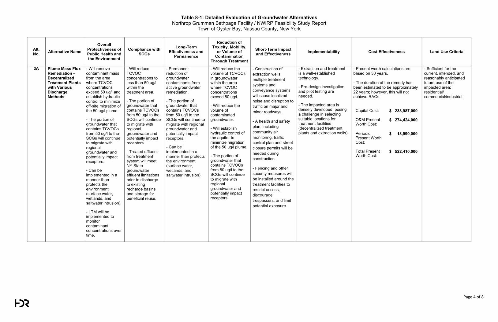
Table 8-1: Detailed Evaluation of Groundwater Alternatives Northrop Grumman Bethpage Facility / NWIRP Feasibility Study Report
Town of Oyster Bay, Nassau County, New York
Page 4 of 8
Alt. No. Alternative Name
Overall Protectiveness of Public Health and the Environment
Compliance with SCGs
Long-Term Effectiveness and
Permanence
Reduction of Toxicity, Mobility,
or Volume of Contamination
Through Treatment
Short-Term Impact and Effectiveness Implementability Cost Effectiveness Land Use Criteria
3A Plume Mass Flux Remediation - Decentralized Treatment Plants with Various Discharge Methods
- Will remove contaminant mass from the area where TCVOC concentrations exceed 50 ug/l and establish hydraulic control to minimize off-site migration of the 50 ug/l plume.
- The portion of groundwater that contains TCVOCs from 50 ug/l to the SCGs will continue to migrate with regional groundwater and potentially impact receptors.
- Can be implemented in a manner than protects the environment (surface water, wetlands, and saltwater intrusion).
- LTM will be implemented to monitor contaminant concentrations over time.
- Will reduce TCVOC concentrations to less than 50 ug/l within the treatment area.
- The portion of groundwater that contains TCVOCs from 50 ug/l to the SCGs will continue to migrate with regional groundwater and potentially impact receptors.
- Treated effluent from treatment system will meet NY State groundwater effluent limitations prior to discharge to existing recharge basins and storage for beneficial reuse.
- Permanent reduction of groundwater contaminants from active groundwater remediation.
- The portion of groundwater that contains TCVOCs from 50 ug/l to the SCGs will continue to migrate with regional groundwater and potentially impact receptors.
- Can be implemented in a manner than protects the environment (surface water, wetlands, and saltwater intrusion).
- Will reduce the volume of TCVOCs in groundwater within the area where TCVOC concentrations exceed 50 ug/l.
- Will reduce the volume of contaminated groundwater.
- Will establish hydraulic control of the aquifer to minimize migration of the 50 ug/l plume.
- The portion of groundwater that contains TCVOCs from 50 ug/l to the SCGs will continue to migrate with regional groundwater and potentially impact receptors.
- Construction of extraction wells, multiple treatment systems and conveyance systems will cause localized noise and disruption to traffic on major and minor roadways.
- A health and safety plan, including community air monitoring, traffic control plan and street closure permits will be needed during construction.
- Fencing and other security measures will be installed around the treatment facilities to restrict access, discourage trespassers, and limit potential exposure.
- Extraction and treatment is a well-established technology.
- Pre-design investigation and pilot testing are needed.
- The impacted area is densely developed, posing a challenge in selecting suitable locations for treatment facilities (decentralized treatment plants and extraction wells).
- Present worth calculations are based on 30 years.
- The duration of the remedy has been estimated to be approximately 22 years; however, this will not achieve RAOs.
Capital Cost:
$ 233,987,000
O&M Present Worth Cost:
$ 274,424,000
Periodic Present Worth Cost:
$ 13,990,000
Total Present Worth Cost:
$ 522,410,000
- Sufficient for the current, intended, and reasonably anticipated future use of the impacted area: residential/ commercial/industrial.
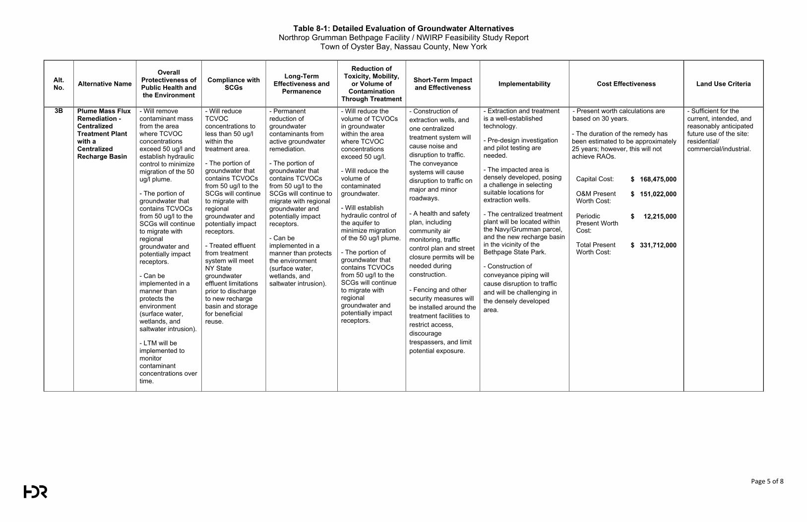
Table 8-1: Detailed Evaluation of Groundwater Alternatives Northrop Grumman Bethpage Facility / NWIRP Feasibility Study Report
Town of Oyster Bay, Nassau County, New York
Page 5 of 8
Alt. No. Alternative Name
Overall Protectiveness of Public Health and the Environment
Compliance with SCGs
Long-Term Effectiveness and
Permanence
Reduction of Toxicity, Mobility,
or Volume of Contamination
Through Treatment
Short-Term Impact and Effectiveness Implementability Cost Effectiveness Land Use Criteria
3B Plume Mass Flux Remediation - Centralized Treatment Plant with a Centralized Recharge Basin
- Will remove contaminant mass from the area where TCVOC concentrations exceed 50 ug/l and establish hydraulic control to minimize migration of the 50 ug/l plume.
- The portion of groundwater that contains TCVOCs from 50 ug/l to the SCGs will continue to migrate with regional groundwater and potentially impact receptors.
- Can be implemented in a manner than protects the environment (surface water, wetlands, and saltwater intrusion).
- LTM will be implemented to monitor contaminant concentrations over time.
- Will reduce TCVOC concentrations to less than 50 ug/l within the treatment area.
- The portion of groundwater that contains TCVOCs from 50 ug/l to the SCGs will continue to migrate with regional groundwater and potentially impact receptors.
- Treated effluent from treatment system will meet NY State groundwater effluent limitations prior to discharge to new recharge basin and storage for beneficial reuse.
- Permanent reduction of groundwater contaminants from active groundwater remediation.
- The portion of groundwater that contains TCVOCs from 50 ug/l to the SCGs will continue to migrate with regional groundwater and potentially impact receptors.
- Can be implemented in a manner than protects the environment (surface water, wetlands, and saltwater intrusion).
- Will reduce the volume of TCVOCs in groundwater within the area where TCVOC concentrations exceed 50 ug/l.
- Will reduce the volume of contaminated groundwater.
- Will establish hydraulic control of the aquifer to minimize migration of the 50 ug/l plume.
- The portion of groundwater that contains TCVOCs from 50 ug/l to the SCGs will continue to migrate with regional groundwater and potentially impact receptors.
- Construction of extraction wells, and one centralized treatment system will cause noise and disruption to traffic. The conveyance systems will cause disruption to traffic on major and minor roadways.
- A health and safety plan, including community air monitoring, traffic control plan and street closure permits will be needed during construction.
- Fencing and other security measures will be installed around the treatment facilities to restrict access, discourage trespassers, and limit potential exposure.
- Extraction and treatment is a well-established technology.
- Pre-design investigation and pilot testing are needed.
- The impacted area is densely developed, posing a challenge in selecting suitable locations for extraction wells.
- The centralized treatment plant will be located within the Navy/Grumman parcel, and the new recharge basin in the vicinity of the Bethpage State Park.
- Construction of conveyance piping will cause disruption to traffic and will be challenging in the densely developed area.
- Present worth calculations are based on 30 years. - The duration of the remedy has been estimated to be approximately 25 years; however, this will not achieve RAOs.
Capital Cost:
$ 168,475,000
O&M Present Worth Cost:
$ 151,022,000
Periodic Present Worth Cost:
$ 12,215,000
Total Present Worth Cost:
$ 331,712,000
- Sufficient for the current, intended, and reasonably anticipated future use of the site: residential/ commercial/industrial.
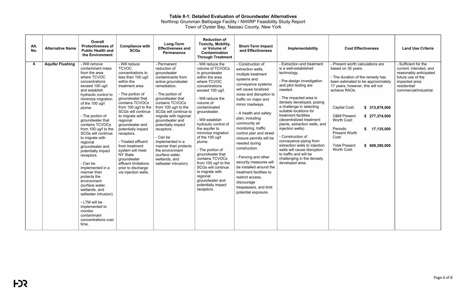
Table 8-1: Detailed Evaluation of Groundwater Alternatives Northrop Grumman Bethpage Facility / NWIRP Feasibility Study Report
Town of Oyster Bay, Nassau County, New York
Page 6 of 8
Alt. No. Alternative Name
Overall Protectiveness of Public Health and the Environment
Compliance with SCGs
Long-Term Effectiveness and
Permanence
Reduction of Toxicity, Mobility,
or Volume of Contamination
Through Treatment
Short-Term Impact and Effectiveness Implementability Cost Effectiveness Land Use Criteria
4 Aquifer Flushing - Will remove contaminant mass from the area where TCVOC concentrations exceed 100 ug/l and establish hydraulic control to minimize migration of the 100 ug/l plume.
- The portion of groundwater that contains TCVOCs from 100 ug/l to the SCGs will continue to migrate with regional groundwater and potentially impact receptors.
- Can be implemented in a manner than protects the environment (surface water, wetlands, and saltwater intrusion).
- LTM will be implemented to monitor contaminant concentrations over time.
- Will reduce TCVOC concentrations to less than 100 ug/l within the treatment area.
- The portion of groundwater that contains TCVOCs from 100 ug/l to the SCGs will continue to migrate with regional groundwater and potentially impact receptors.
- Treated effluent from treatment system will meet NY State groundwater effluent limitations prior to discharge via injection wells.
- Permanent reduction of groundwater contaminants from active groundwater remediation.
- The portion of groundwater that contains TCVOCs from 100 ug/l to the SCGs will continue to migrate with regional groundwater and potentially impact receptors.
- Can be implemented in a manner than protects the environment (surface water, wetlands, and saltwater intrusion).
- Will reduce the volume of TCVOCs in groundwater within the area where TCVOC concentrations exceed 100 ug/l.
- Will reduce the volume of contaminated groundwater.
- Will establish hydraulic control of the aquifer to minimize migration of the 100 ug/l plume.
- The portion of groundwater that contains TCVOCs from 100 ug/l to the SCGs will continue to migrate with regional groundwater and potentially impact receptors.
- Construction of extraction wells, multiple treatment systems and conveyance systems will cause localized noise and disruption to traffic on major and minor roadways.
- A health and safety plan, including community air monitoring, traffic control plan and street closure permits will be needed during construction.
- Fencing and other security measures will be installed around the treatment facilities to restrict access, discourage trespassers, and limit potential exposure.
- Extraction and treatment is a well-established technology.
- Pre-design investigation and pilot testing are needed.
- The impacted area is densely developed, posing a challenge in selecting suitable locations for treatment facilities (decentralized treatment plants, extraction wells, and injection wells).
- Construction of conveyance piping from extraction wells to injection wells will cause disruption to traffic and will be challenging in the densely developed area.
- Present worth calculations are based on 30 years. - The duration of the remedy has been estimated to be approximately 17 years; however, this will not achieve RAOs.
Capital Cost:
$ 313,879,000
O&M Present Worth Cost:
$ 277,374,000
Periodic Present Worth Cost:
$ 17,135,000
Total Present Worth Cost:
$ 608,390,000
- Sufficient for the current, intended, and reasonably anticipated future use of the impacted area: residential/ commercial/industrial.
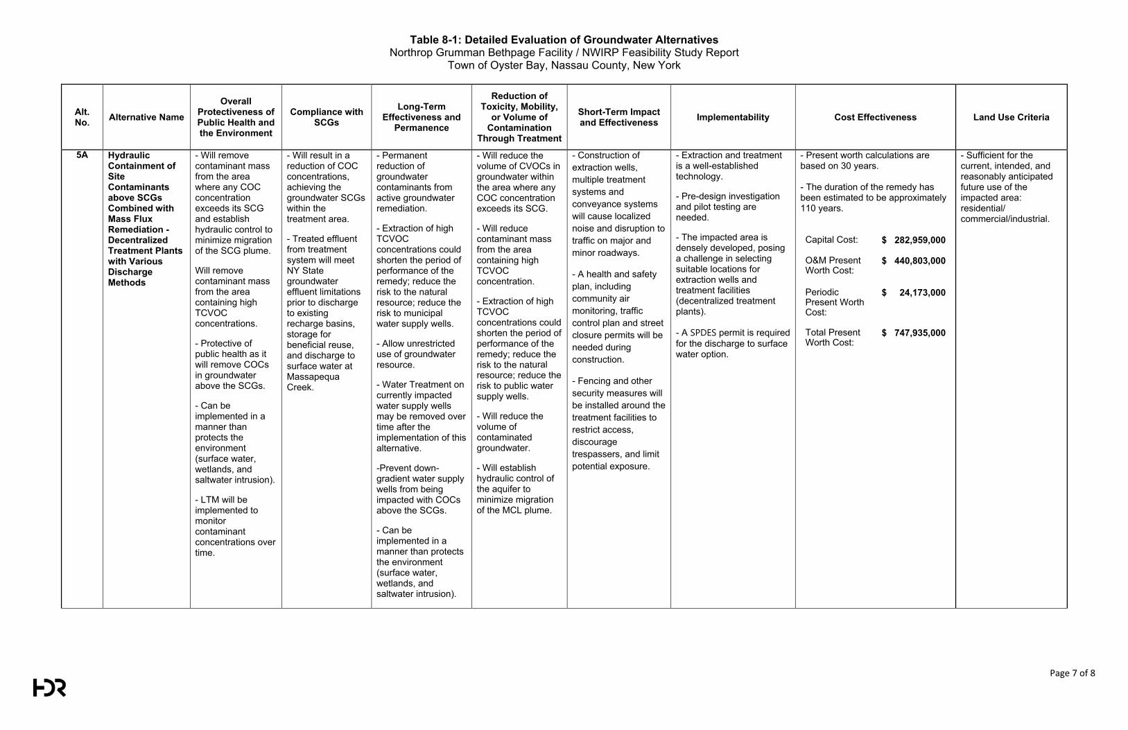
Table 8-1: Detailed Evaluation of Groundwater Alternatives Northrop Grumman Bethpage Facility / NWIRP Feasibility Study Report
Town of Oyster Bay, Nassau County, New York
Page 7 of 8
Alt. No. Alternative Name
Overall Protectiveness of Public Health and the Environment
Compliance with SCGs
Long-Term Effectiveness and
Permanence
Reduction of Toxicity, Mobility,
or Volume of Contamination
Through Treatment
Short-Term Impact and Effectiveness Implementability Cost Effectiveness Land Use Criteria
5A Hydraulic Containment of Site Contaminants above SCGs Combined with Mass Flux Remediation - Decentralized Treatment Plants with Various Discharge Methods
- Will remove contaminant mass from the area where any COC concentration exceeds its SCG and establish hydraulic control to minimize migration of the SCG plume.
Will remove contaminant mass from the area containing high TCVOC concentrations.
- Protective of public health as it will remove COCs in groundwater above the SCGs.
- Can be implemented in a manner than protects the environment (surface water, wetlands, and saltwater intrusion).
- LTM will be implemented to monitor contaminant concentrations over time.
- Will result in a reduction of COC concentrations, achieving the groundwater SCGs within the treatment area.
- Treated effluent from treatment system will meet NY State groundwater effluent limitations prior to discharge to existing recharge basins, storage for beneficial reuse, and discharge to surface water at Massapequa Creek.
- Permanent reduction of groundwater contaminants from active groundwater remediation.
- Extraction of high TCVOC concentrations could shorten the period of performance of the remedy; reduce the risk to the natural resource; reduce the risk to municipal water supply wells.
- Allow unrestricted use of groundwater resource.
- Water Treatment on currently impacted water supply wells may be removed over time after the implementation of this alternative.
-Prevent down-gradient water supply wells from being impacted with COCs above the SCGs.
- Can be implemented in a manner than protects the environment (surface water, wetlands, and saltwater intrusion).
- Will reduce the volume of CVOCs in groundwater within the area where any COC concentration exceeds its SCG.
- Will reduce contaminant mass from the area containing high TCVOC concentration.
- Extraction of high TCVOC concentrations could shorten the period of performance of the remedy; reduce the risk to the natural resource; reduce the risk to public water supply wells.
- Will reduce the volume of contaminated groundwater.
- Will establish hydraulic control of the aquifer to minimize migration of the MCL plume.
- Construction of extraction wells, multiple treatment systems and conveyance systems will cause localized noise and disruption to traffic on major and minor roadways.
- A health and safety plan, including community air monitoring, traffic control plan and street closure permits will be needed during construction.
- Fencing and other security measures will be installed around the treatment facilities to restrict access, discourage trespassers, and limit potential exposure.
- Extraction and treatment is a well-established technology.
- Pre-design investigation and pilot testing are needed.
- The impacted area is densely developed, posing a challenge in selecting suitable locations for extraction wells and treatment facilities (decentralized treatment plants).
- A SPDES permit is required for the discharge to surface water option.
- Present worth calculations are based on 30 years. - The duration of the remedy has been estimated to be approximately 110 years.
Capital Cost:
$ 282,959,000
O&M Present Worth Cost:
$ 440,803,000
Periodic Present Worth Cost:
$ 24,173,000
Total Present Worth Cost:
$ 747,935,000
- Sufficient for the current, intended, and reasonably anticipated future use of the impacted area: residential/ commercial/industrial.
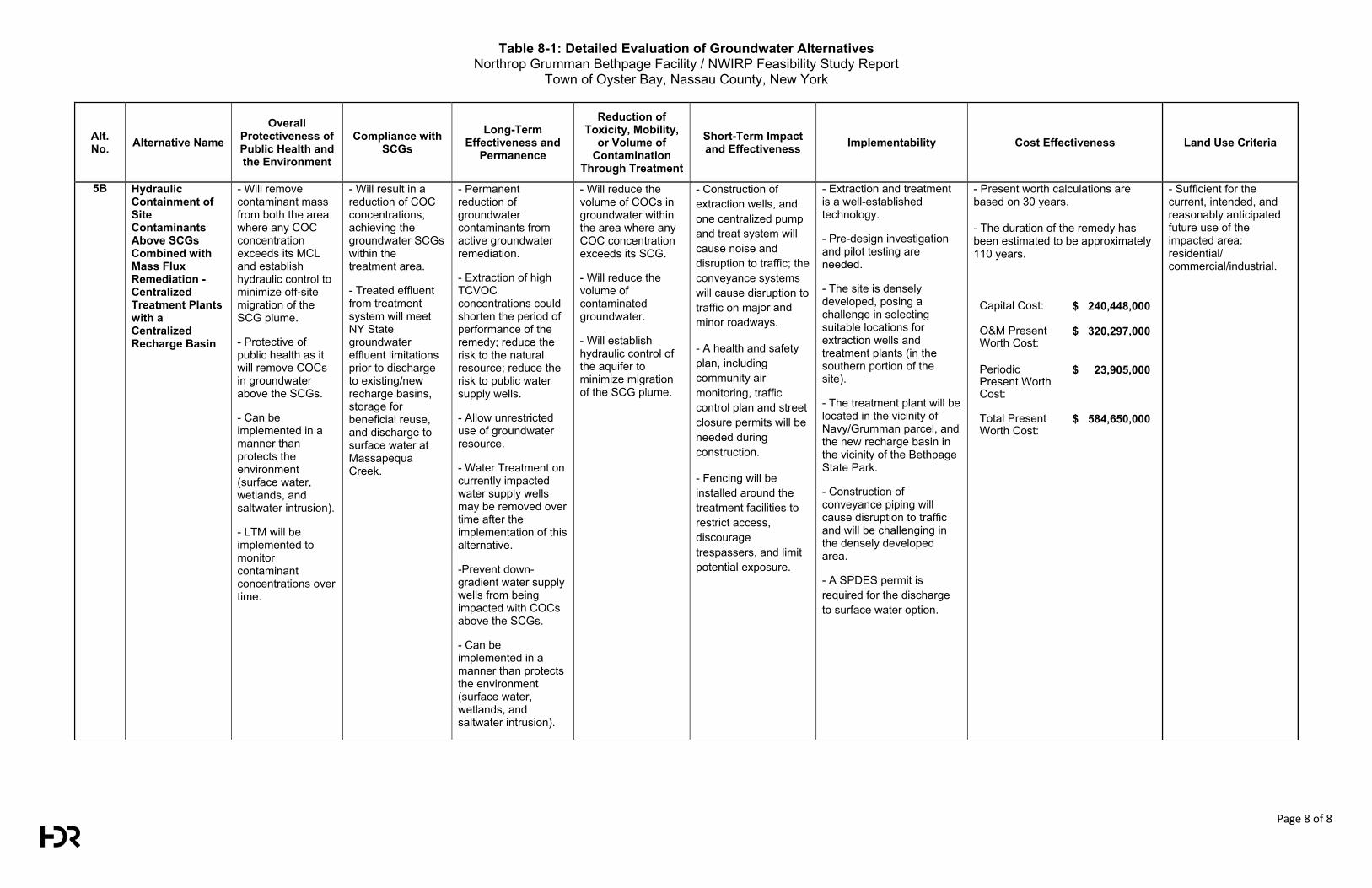
Table 8-1: Detailed Evaluation of Groundwater Alternatives Northrop Grumman Bethpage Facility / NWIRP Feasibility Study Report
Town of Oyster Bay, Nassau County, New York
Page 8 of 8
Alt. No. Alternative Name
Overall Protectiveness of Public Health and the Environment
Compliance with SCGs
Long-Term Effectiveness and
Permanence
Reduction of Toxicity, Mobility,
or Volume of Contamination
Through Treatment
Short-Term Impact and Effectiveness Implementability Cost Effectiveness Land Use Criteria
5B Hydraulic Containment of Site Contaminants Above SCGs Combined with Mass Flux Remediation - Centralized Treatment Plants with a Centralized Recharge Basin
- Will remove contaminant mass from both the area where any COC concentration exceeds its MCL and establish hydraulic control to minimize off-site migration of the SCG plume.
- Protective of public health as it will remove COCs in groundwater above the SCGs.
- Can be implemented in a manner than protects the environment (surface water, wetlands, and saltwater intrusion).
- LTM will be implemented to monitor contaminant concentrations over time.
- Will result in a reduction of COC concentrations, achieving the groundwater SCGs within the treatment area.
- Treated effluent from treatment system will meet NY State groundwater effluent limitations prior to discharge to existing/new recharge basins, storage for beneficial reuse, and discharge to surface water at Massapequa Creek.
- Permanent reduction of groundwater contaminants from active groundwater remediation.
- Extraction of high TCVOC concentrations could shorten the period of performance of the remedy; reduce the risk to the natural resource; reduce the risk to public water supply wells.
- Allow unrestricted use of groundwater resource.
- Water Treatment on currently impacted water supply wells may be removed over time after the implementation of this alternative.
-Prevent down-gradient water supply wells from being impacted with COCs above the SCGs.
- Can be implemented in a manner than protects the environment (surface water, wetlands, and saltwater intrusion).
- Will reduce the volume of COCs in groundwater within the area where any COC concentration exceeds its SCG.
- Will reduce the volume of contaminated groundwater.
- Will establish hydraulic control of the aquifer to minimize migration of the SCG plume.
- Construction of extraction wells, and one centralized pump and treat system will cause noise and disruption to traffic; the conveyance systems will cause disruption to traffic on major and minor roadways.
- A health and safety plan, including community air monitoring, traffic control plan and street closure permits will be needed during construction.
- Fencing will be installed around the treatment facilities to restrict access, discourage trespassers, and limit potential exposure.
- Extraction and treatment is a well-established technology.
- Pre-design investigation and pilot testing are needed.
- The site is densely developed, posing a challenge in selecting suitable locations for extraction wells and treatment plants (in the southern portion of the site).
- The treatment plant will be located in the vicinity of Navy/Grumman parcel, and the new recharge basin in the vicinity of the Bethpage State Park.
- Construction of conveyance piping will cause disruption to traffic and will be challenging in the densely developed area.
- A SPDES permit is required for the discharge to surface water option.
- Present worth calculations are based on 30 years.
- The duration of the remedy has been estimated to be approximately 110 years.
Capital Cost:
$ 240,448,000
O&M Present Worth Cost:
$ 320,297,000
Periodic Present Worth Cost:
$ 23,905,000
Total Present Worth Cost:
$ 584,650,000
- Sufficient for the current, intended, and reasonably anticipated future use of the impacted area: residential/ commercial/industrial.
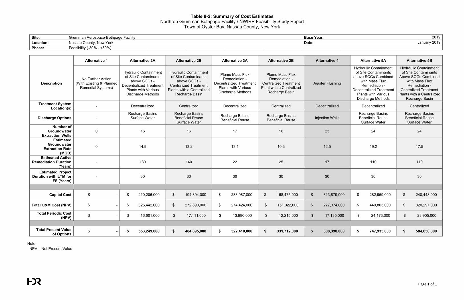
Table 8-2: Summary of Cost Estimates Northrop Grumman Bethpage Facility / NWIRP Feasibility Study Report
Town of Oyster Bay, Nassau County, New York
Page 1 of 1
Site: Grumman Aerospace-Bethpage Facility Base Year: 2019Location: Nassau County, New York Date: January 2019Phase: Feasibility (-30% - +50%)
Alternative 1 Alternative 2A Alternative 2B Alternative 3A Alternative 3B Alternative 4 Alternative 5A Alternative 5B
Description No Further Action
(With Existing & Planned Remedial Systems)
Hydraulic Containment of Site Contaminants
above SCGs - Decentralized Treatment
Plants with Various Discharge Methods
Hydraulic Containment of Site Contaminants
above SCGs - Centralized Treatment
Plants with a Centralized Recharge Basin
Plume Mass Flux Remediation -
Decentralized Treatment Plants with Various Discharge Methods
Plume Mass Flux Remediation -
Centralized Treatment Plant with a Centralized
Recharge Basin
Aquifer Flushing
Hydraulic Containment of Site Contaminants
above SCGs Combined with Mass Flux Remediation -
Decentralized Treatment Plants with Various Discharge Methods
Hydraulic Containment of Site Contaminants
Above SCGs Combined with Mass Flux Remediation -
Centralized Treatment Plants with a Centralized
Recharge Basin Treatment System
Location(s) - Decentralized Centralized Decentralized Centralized Decentralized Decentralized Centralized
Discharge Options - Recharge Basins
Surface Water
Recharge Basins Beneficial Reuse
Surface Water
Recharge Basins Beneficial Reuse
Recharge Basins Beneficial Reuse Injection Wells
Recharge Basins Beneficial Reuse
Surface Water
Recharge Basins Beneficial Reuse
Surface Water Number of
Groundwater Extraction Wells
0 16 16 17 16 23 24 24
Estimated Groundwater
Extraction Rate (MGD)
0 14.9 13.2 13.1 10.3 12.5 19.2 17.5
Estimated Active Remediation Duration
(Years) - 130 140 22 25 17 110 110
Estimated Project Duration with LTM for
FS (Years) - 30 30 30 30 30 30 30
Capital Cost $ - $ 210,206,000 $ 194,894,000 $ 233,987,000 $ 168,475,000 $ 313,879,000 $ 282,959,000 $ 240,448,000
Total O&M Cost (NPV) $ - $ 326,442,000 $ 272,890,000 $ 274,424,000 $ 151,022,000 $ 277,374,000 $ 440,803,000 $ 320,297,000
Total Periodic Cost (NPV) $ - $ 16,601,000 $ 17,111,000 $ 13,990,000 $ 12,215,000 $ 17,135,000 $ 24,173,000 $ 23,905,000
Total Present Value of Options
$ - $ 553,249,000 $ 484,895,000 $ 522,410,000 $ 331,712,000 $ 608,390,000 $ 747,935,000 $ 584,650,000
Note: NPV – Net Present Value
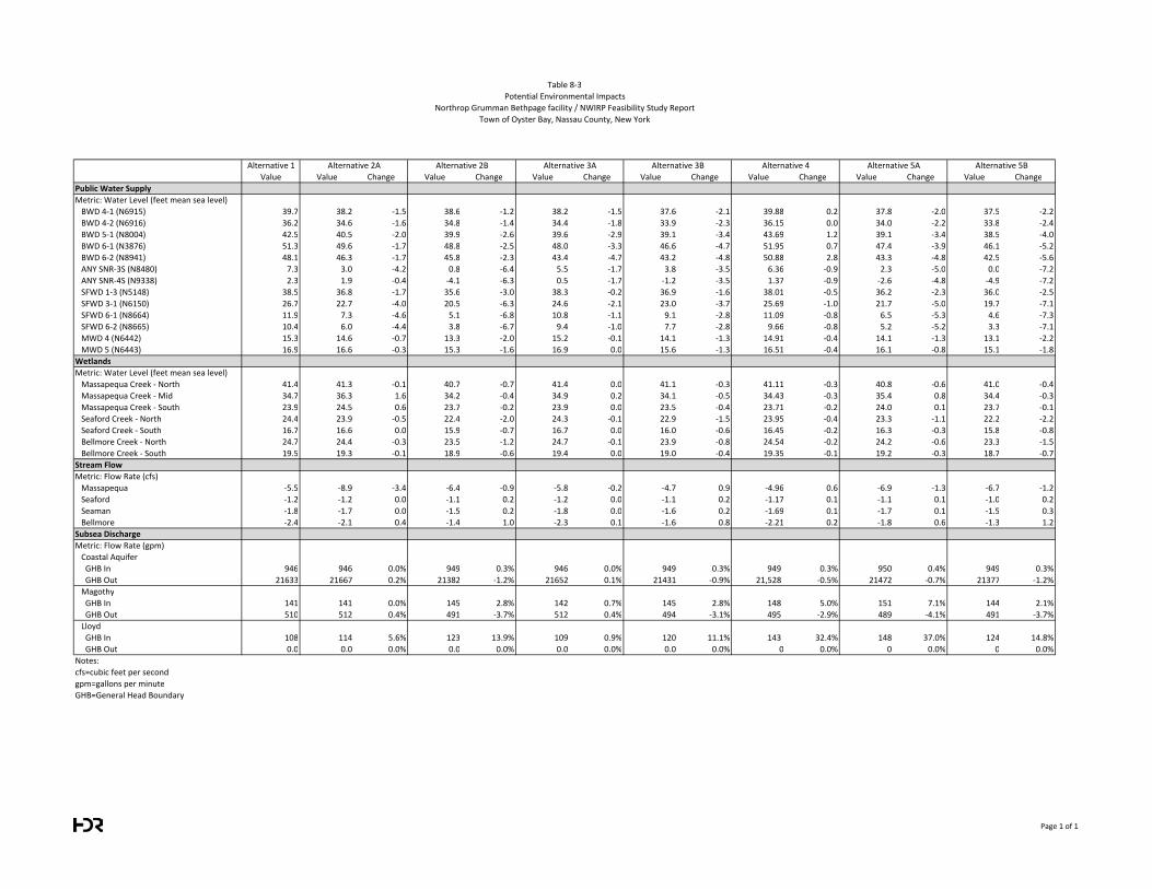
18312 17112 17052 15102 16072 21302 20102
7962 14.9 13.2 13.1 10.3 11.7 19.2 17.5
sc1bFinal Scen2aV11 10350 Scen2bV22a 9150 Scen3aV8 9090 Scen3bV25 7140 Scen4V8 8110 Scen5aV5 13340 Scen5bV10 12140
Alternative 1
Value Value Change Value Change Value Change Value Change Value Change Value Change Value Change
Public Water Supply
Metric: Water Level (feet mean sea level)
BWD 4-1 (N6915) 39.7 38.2 -1.5 38.6 -1.2 38.2 -1.5 37.6 -2.1 39.88 0.2 37.8 -2.0 37.5 -2.2
BWD 4-2 (N6916) 36.2 34.6 -1.6 34.8 -1.4 34.4 -1.8 33.9 -2.3 36.15 0.0 34.0 -2.2 33.8 -2.4
BWD 5-1 (N8004) 42.5 40.5 -2.0 39.9 -2.6 39.6 -2.9 39.1 -3.4 43.69 1.2 39.1 -3.4 38.5 -4.0
BWD 6-1 (N3876) 51.3 49.6 -1.7 48.8 -2.5 48.0 -3.3 46.6 -4.7 51.95 0.7 47.4 -3.9 46.1 -5.2
BWD 6-2 (N8941) 48.1 46.3 -1.7 45.8 -2.3 43.4 -4.7 43.2 -4.8 50.88 2.8 43.3 -4.8 42.5 -5.6
ANY SNR-3S (N8480) 7.3 3.0 -4.2 0.8 -6.4 5.5 -1.7 3.8 -3.5 6.36 -0.9 2.3 -5.0 0.0 -7.2
ANY SNR-4S (N9338) 2.3 1.9 -0.4 -4.1 -6.3 0.5 -1.7 -1.2 -3.5 1.37 -0.9 -2.6 -4.8 -4.9 -7.2
SFWD 1-3 (N5148) 38.5 36.8 -1.7 35.6 -3.0 38.3 -0.2 36.9 -1.6 38.01 -0.5 36.2 -2.3 36.0 -2.5
SFWD 3-1 (N6150) 26.7 22.7 -4.0 20.5 -6.3 24.6 -2.1 23.0 -3.7 25.69 -1.0 21.7 -5.0 19.7 -7.1
SFWD 6-1 (N8664) 11.9 7.3 -4.6 5.1 -6.8 10.8 -1.1 9.1 -2.8 11.09 -0.8 6.5 -5.3 4.6 -7.3
SFWD 6-2 (N8665) 10.4 6.0 -4.4 3.8 -6.7 9.4 -1.0 7.7 -2.8 9.66 -0.8 5.2 -5.2 3.3 -7.1
MWD 4 (N6442) 15.3 14.6 -0.7 13.3 -2.0 15.2 -0.1 14.1 -1.3 14.91 -0.4 14.1 -1.3 13.1 -2.2
MWD 5 (N6443) 16.9 16.6 -0.3 15.3 -1.6 16.9 0.0 15.6 -1.3 16.51 -0.4 16.1 -0.8 15.1 -1.8
Wetlands
Metric: Water Level (feet mean sea level)
Massapequa Creek - North 41.4 41.3 -0.1 40.7 -0.7 41.4 0.0 41.1 -0.3 41.11 -0.3 40.8 -0.6 41.0 -0.4
Massapequa Creek - Mid 34.7 36.3 1.6 34.2 -0.4 34.9 0.2 34.1 -0.5 34.43 -0.3 35.4 0.8 34.4 -0.3
Massapequa Creek - South 23.9 24.5 0.6 23.7 -0.2 23.9 0.0 23.5 -0.4 23.71 -0.2 24.0 0.1 23.7 -0.1
Seaford Creek - North 24.4 23.9 -0.5 22.4 -2.0 24.3 -0.1 22.9 -1.5 23.95 -0.4 23.3 -1.1 22.2 -2.2
Seaford Creek - South 16.7 16.6 0.0 15.9 -0.7 16.7 0.0 16.0 -0.6 16.45 -0.2 16.3 -0.3 15.8 -0.8
Bellmore Creek - North 24.7 24.4 -0.3 23.5 -1.2 24.7 -0.1 23.9 -0.8 24.54 -0.2 24.2 -0.6 23.3 -1.5
Bellmore Creek - South 19.5 19.3 -0.1 18.9 -0.6 19.4 0.0 19.0 -0.4 19.35 -0.1 19.2 -0.3 18.7 -0.7
Stream Flow
Metric: Flow Rate (cfs)
Massapequa -5.5 -8.9 -3.4 -6.4 -0.9 -5.8 -0.2 -4.7 0.9 -4.96 0.6 -6.9 -1.3 -6.7 -1.2
Seaford -1.2 -1.2 0.0 -1.1 0.2 -1.2 0.0 -1.1 0.2 -1.17 0.1 -1.1 0.1 -1.0 0.2
Seaman -1.8 -1.7 0.0 -1.5 0.2 -1.8 0.0 -1.6 0.2 -1.69 0.1 -1.7 0.1 -1.5 0.3
Bellmore -2.4 -2.1 0.4 -1.4 1.0 -2.3 0.1 -1.6 0.8 -2.21 0.2 -1.8 0.6 -1.3 1.2
Subsea Discharge
Metric: Flow Rate (gpm)
Coastal Aquifer
GHB In 946 946 0.0% 949 0.3% 946 0.0% 949 0.3% 949 0.3% 950 0.4% 949 0.3%
GHB Out 21633 21667 0.2% 21382 -1.2% 21652 0.1% 21431 -0.9% 21,528 -0.5% 21472 -0.7% 21377 -1.2%
Magothy
GHB In 141 141 0.0% 145 2.8% 142 0.7% 145 2.8% 148 5.0% 151 7.1% 144 2.1%
GHB Out 510 512 0.4% 491 -3.7% 512 0.4% 494 -3.1% 495 -2.9% 489 -4.1% 491 -3.7%
Lloyd
GHB In 108 114 5.6% 123 13.9% 109 0.9% 120 11.1% 143 32.4% 148 37.0% 124 14.8%
GHB Out 0.0 0.0 0.0% 0.0 0.0% 0.0 0.0% 0.0 0.0% 0 0.0% 0 0.0% 0 0.0%
Notes:
cfs=cubic feet per second
gpm=gallons per minute
GHB=General Head Boundary
Alternative 5B
Table 8-3
Potential Environmental Impacts
Northrop Grumman Bethpage facility / NWIRP Feasibility Study Report
Town of Oyster Bay, Nassau County, New York
Alternative 2A Alternative 2B Alternative 3A Alternative 3B Alternative 4 Alternative 5A
Page 1 of 1

Northrop Grumman – Bethpage Facility/Naval Weapons Industrial Reserve Plant Feasibility Study Report April 2019
FIGURES
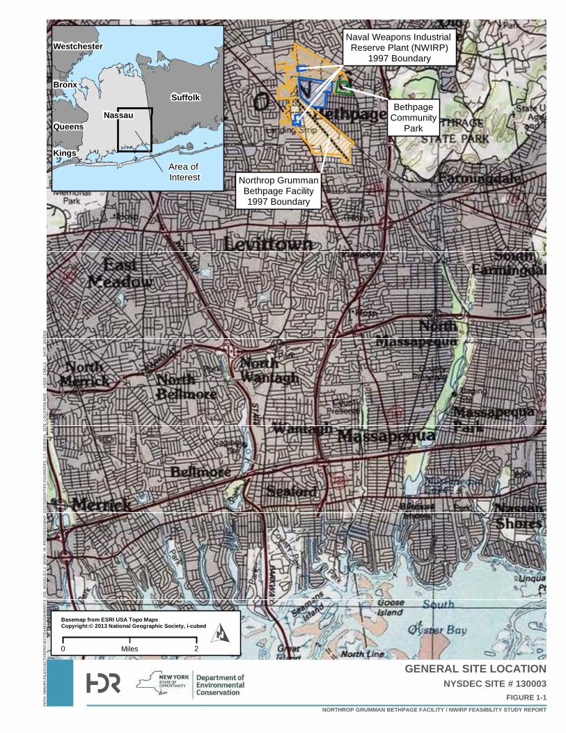
Northrop GrummanBethpage Facility1997 Boundary
Naval Weapons Industrial Reserve Plant (NWIRP)
1997 Boundary
BethpageCommunity
Park
PATH
: \\MA
HPI-F
ILE01
\ACT
IVEPR
OJEC
TS\44
92\10
0548
40\7.
0_GI
S_MO
DELS
\7.2_
WORK
_IN_P
ROGR
ESS\M
AP_D
OCS\D
RAFT
\FS FI
GURE
S\FS_
1-1_G
ENER
AL_S
ITE_L
OCAT
ION.
MXD
- US
ER: C
MILL
S - D
ATE:
2/5/2
019
GENERAL SITE LOCATION
FIGURE 1-1NYSDEC SITE # 130003
NORTHROP GRUMMAN BETHPAGE FACILITY / NWIRP FEASIBILITY STUDY REPORT
0 2MilesO
Basemap from ESRI USA Topo MapsCopyright:© 2013 National Geographic Society, i-cubed
SuffolkNassau
Queens
Westchester
Bronx
KingsArea of Interest
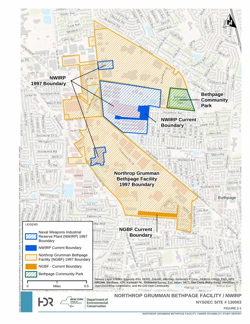
Northrop GrummanBethpage Facility
1997 Boundary
BethpageCommunityPark
NWIRP1997 Boundary
NWIRP CurrentBoundary
NGBF CurrentBoundary
PATH
: \\MA
HPI-F
ILE01
\ACT
IVEPR
OJEC
TS\44
92\10
0548
40\7.
0_GI
S_MO
DELS
\7.2_
WORK
_IN_P
ROGR
ESS\M
AP_D
OCS\D
RAFT
\FS FI
GURE
S\FS_
2-1_S
PECI
FIC_S
ITE_L
OCAT
ION.
MXD
- US
ER: C
MILL
S - D
ATE:
2/5/2
019
NORTHROP GRUMMAN BETHPAGE FACILITY / NWIRP
FIGURE 2-1NYSDEC SITE # 130003
NORTHROP GRUMMAN BETHPAGE FACILITY / NWIRP FEASIBILITY STUDY REPORT
0 0.5Miles
O
LEGEND
Naval Weapons IndustrialReserve Plant (NWIRP) 1997Boundary
NWIRP Current Boundary
Northrop Grumman BethpageFacility (NGBF) 1997 Boundary
NGBF - Current Boundary
Bethpage Community ParkService Layer Credits: Sources: Esri, HERE, Garmin, Intermap, increment P Corp., GEBCO, USGS, FAO, NPS,NRCAN, GeoBase, IGN, Kadaster NL, Ordnance Survey, Esri Japan, METI, Esri China (Hong Kong), swisstopo, ©OpenStreetMap contributors, and the GIS User Community
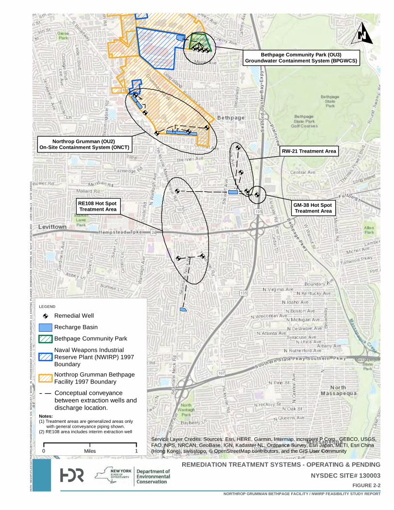
@A
@A
@A@A
@A@A
@A
@A
@A
@A @A@A
@A@A@A@A
@A
@A
@A
@A @A@A
@A@A@A@A
PATH
: \\MA
HPI-F
ILE01
\ACT
IVEPR
OJEC
TS\44
92\10
0548
40\7.
0_GI
S_MO
DELS
\7.2_
WOR
K_IN
_PRO
GRES
S\MA
P_DO
CS\D
RAFT
\FS FI
GURE
S\FS_
2-2_E
XISTIN
G_PL
ANNE
D_RE
MEDI
ATIO
N_SY
STEM
S_NG
_NAV
Y_20
1812
31.M
XD -
USE
R: C
MILL
S - D
ATE:
2/5/2
019
REMEDIATION TREATMENT SYSTEMS - OPERATING & PENDING
FIGURE 2-2NYSDEC SITE# 130003
0 1Miles
LEGEND
@A Remedial Well
Recharge Basin
Bethpage Community Park
Naval Weapons IndustrialReserve Plant (NWIRP) 1997Boundary
Northrop Grumman BethpageFacility 1997 Boundary
Bethpage Community Park (OU3)Groundwater Containment System (BPGWCS)
RW-21 Treatment Area
GM-38 Hot Spot Treatment Area
Northrop Grumman (OU2) On-Site Containment System (ONCT)
RE108 Hot Spot Treatment Area
Notes:(1) Treatment areas are generalized areas only with general conveyance piping shown. (2) RE108 area includes interim extraction well
O
NORTHROP GRUMMAN BETHPAGE FACILITY / NWIRP FEASIBILITY STUDY REPORT
Service Layer Credits: Sources: Esri, HERE, Garmin, Intermap, increment P Corp., GEBCO, USGS,FAO, NPS, NRCAN, GeoBase, IGN, Kadaster NL, Ordnance Survey, Esri Japan, METI, Esri China(Hong Kong), swisstopo, © OpenStreetMap contributors, and the GIS User Community
Conceptual conveyancebetween extraction wells and discharge location.
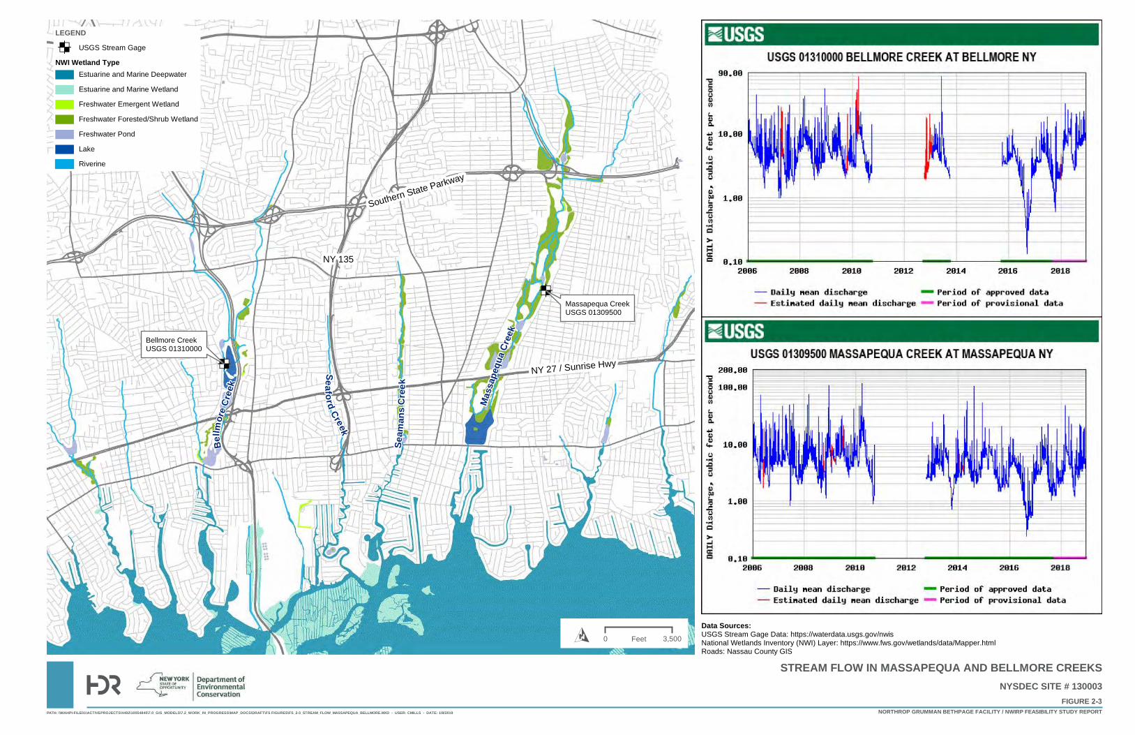
ED
ED
Mass
apeq
uaCr
eek
Seam
ansC
re ek
Seaford Creek
Bellm
oreCr
eek
Massapequa CreekUSGS 01309500
Bellmore CreekUSGS 01310000
Southern State Parkway
NY 135
NY 27 / Sunrise Hwy
PATH: \\MAHPI-FILE01\ACTIVEPROJECTS\4492\10054840\7.0_GIS_MODELS\7.2_WORK_IN_PROGRESS\MAP_DOCS\DRAFT\FS FIGURES\FS_2-3_STREAM_FLOW_MASSAPEQUA_BELLMORE.MXD - USER: CMILLS - DATE: 1/8/2019
FIGURE 2-3NYSDEC SITE # 130003
NORTHROP GRUMMAN BETHPAGE FACILITY / NWIRP FEASIBILITY STUDY REPORT
STREAM FLOW IN MASSAPEQUA AND BELLMORE CREEKS
Data Sources:USGS Stream Gage Data: https://waterdata.usgs.gov/nwisNational Wetlands Inventory (NWI) Layer: https://www.fws.gov/wetlands/data/Mapper.htmlRoads: Nassau County GIS
LEGEND
ED USGS Stream Gage
NWI Wetland TypeEstuarine and Marine Deepwater
Estuarine and Marine Wetland
Freshwater Emergent Wetland
Freshwater Forested/Shrub Wetland
Freshwater Pond
Lake
Riverine
0 3,500FeetO
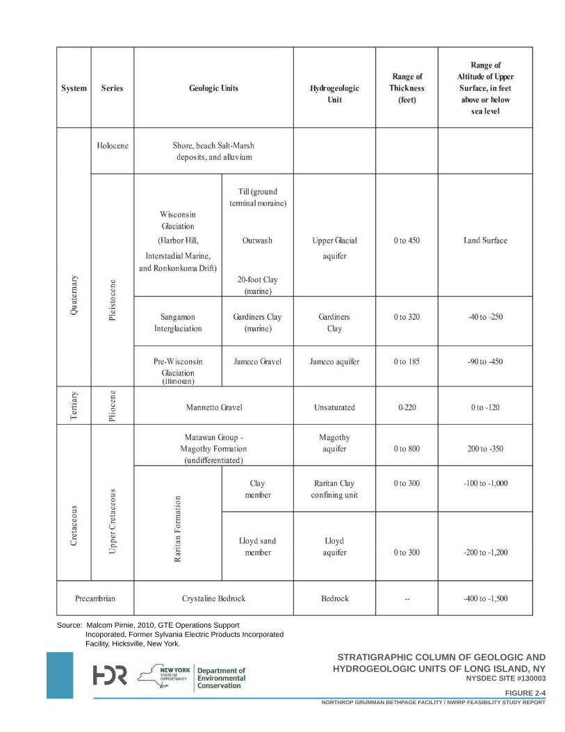
Source: Malcom Pirnie, 2010, GTE Operations Support Incoporated, Former Sylvania Electric Products Incorporated Facility, Hicksville, New York.
NYSDEC SITE #130003
NORTHROP GRUMMAN BETHPAGE FACILITY / NWIRP FEASIBILITY STUDY REPORT
FIGURE 2-4
STRATIGRAPHIC COLUMN OF GEOLOGIC AND HYDROGEOLOGIC UNITS OF LONG ISLAND, NY
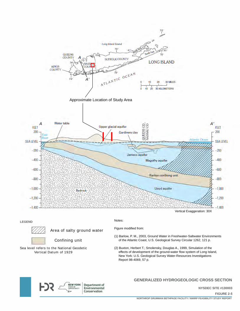
Notes:
Figure modified from:
(1) Barlow, P. M., 2003, Ground Water in Freshwater-Saltwater Environmentsof the Atlantic Coast, U.S. Geological Survey Circular 1262, 121 p.
(2) Buxton, Herbert T.; Smolensky, Douglas A., 1999, Simulation of theeffects of development of the ground-water flow system of Long Island,New York: U.S. Geological Survey Water-Resources InvestigationsReport 98-4069, 57 p.
Vertical Exaggeration: 30X
Area of salty ground water
Confining unit
Sea level refers to the National Geodetic Vertical Datum of 1929
LEGEND
Approximate Location of Study Area
GENERALIZED HYDROGEOLOGIC CROSS SECTION
NORTHROP GRUMMAN BETHPAGE FACILITY / NWIRP FEASIBILITY STUDY REPORT
NYSDEC SITE #130003
FIGURE 2-5
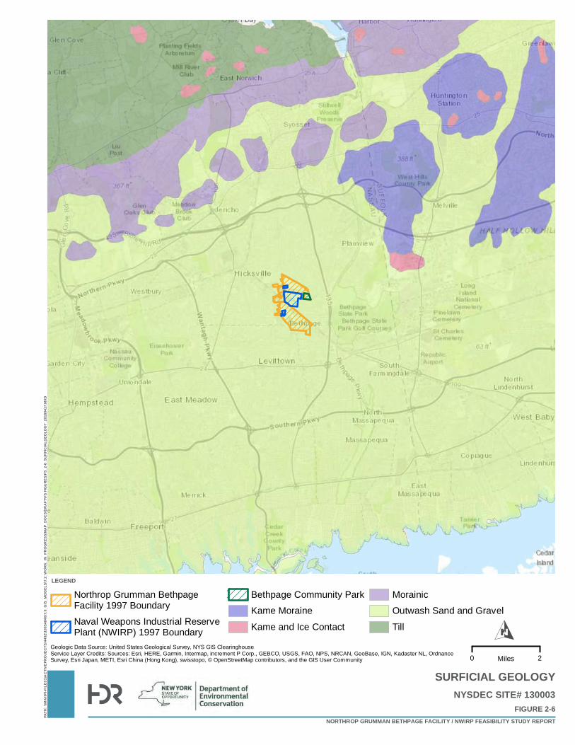
PATH
: \\MA
HPI-F
ILE01
\ACT
IVEPR
OJEC
TS\44
92\10
0548
40\7.
0_GI
S_MO
DELS
\7.2_
WOR
K_IN
_PRO
GRES
S\MAP
_DOC
S\DRA
FT\FS
FIGU
RES\F
S_2-6
_SUR
FICIA
LGEO
LOGY
_201
8041
7.MXD
SURFICIAL GEOLOGY
FIGURE 2-6NYSDEC SITE# 130003
NORTHROP GRUMMAN BETHPAGE FACILITY / NWIRP FEASIBILITY STUDY REPORT
0 2Miles
O
LEGEND
Northrop Grumman BethpageFacility 1997 BoundaryNaval Weapons Industrial ReservePlant (NWIRP) 1997 Boundary
Bethpage Community ParkKame Moraine
Kame and Ice Contact
MorainicOutwash Sand and Gravel
Till
Geologic Data Source: United States Geological Survey, NYS GIS ClearinghouseService Layer Credits: Sources: Esri, HERE, Garmin, Intermap, increment P Corp., GEBCO, USGS, FAO, NPS, NRCAN, GeoBase, IGN, Kadaster NL, OrdnanceSurvey, Esri Japan, METI, Esri China (Hong Kong), swisstopo, © OpenStreetMap contributors, and the GIS User Community
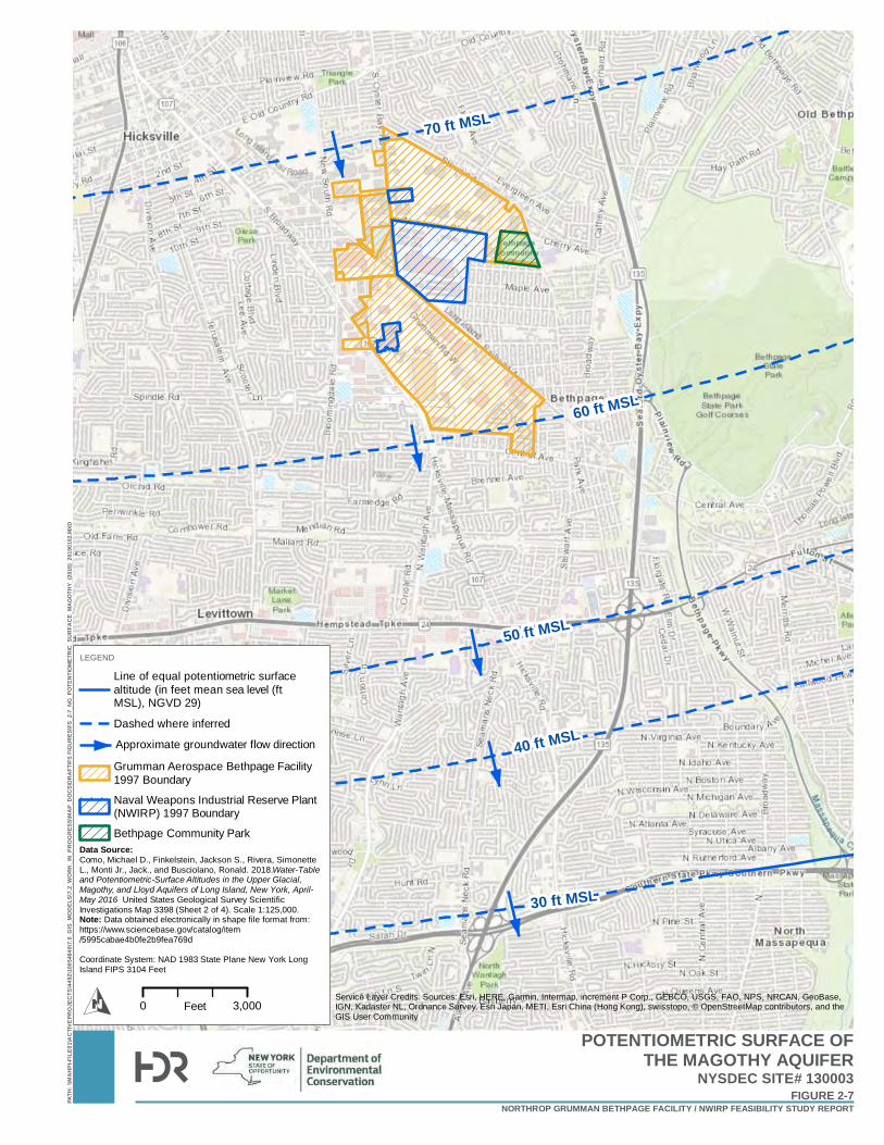
70 ft MSL
60 ft MSL
50 ft MSL
40 ft MSL
30 ft MSL
PATH
: \\MA
HPI-F
ILE01
\ACT
IVEPR
OJEC
TS\44
92\10
0548
40\7.
0_GI
S_MO
DELS
\7.2_
WOR
K_IN
_PRO
GRES
S\MA
P_DO
CS\D
RAFT
\FS FI
GURE
S\FS_
2-7_N
G_PO
TENT
IOME
TRIC
_SUR
FACE
_MAG
OTHY
_(201
6)_20
1901
02.M
XD
POTENTIOMETRIC SURFACE OFTHE MAGOTHY AQUIFER
FIGURE 2-7NYSDEC SITE# 130003
NORTHROP GRUMMAN BETHPAGE FACILITY / NWIRP FEASIBILITY STUDY REPORT
O
LEGEND
Line of equal potentiometric surfacealtitude (in feet mean sea level (ftMSL), NGVD 29)
Dashed where inferred
0 3,000FeetService Layer Credits: Sources: Esri, HERE, Garmin, Intermap, increment P Corp., GEBCO, USGS, FAO, NPS, NRCAN, GeoBase,IGN, Kadaster NL, Ordnance Survey, Esri Japan, METI, Esri China (Hong Kong), swisstopo, © OpenStreetMap contributors, and theGIS User Community
Data Source:Como, Michael D., Finkelstein, Jackson S., Rivera, SimonetteL., Monti Jr., Jack., and Busciolano, Ronald. 2018.Water-Tableand Potentiometric-Surface Altitudes in the Upper Glacial,Magothy, and Lloyd Aquifers of Long Island, New York, April-May 2016 United States Geological Survey ScientificInvestigations Map 3398 (Sheet 2 of 4). Scale 1:125,000.Note: Data obtained electronically in shape file format from:https://www.sciencebase.gov/catalog/item/5995cabae4b0fe2b9fea769d
Coordinate System: NAD 1983 State Plane New York LongIsland FIPS 3104 Feet
Grumman Aerospace Bethpage Facility1997 Boundary
Naval Weapons Industrial Reserve Plant(NWIRP) 1997 Boundary
Bethpage Community Park
Approximate groundwater flow direction
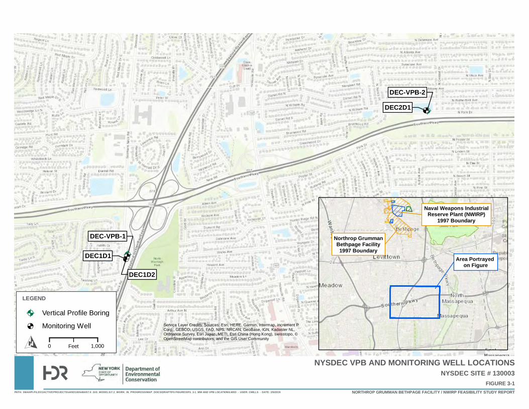
@A
@A
&<&<
&<
DEC1D1
DEC1D2
DEC2D1
DEC-VPB-1
DEC-VPB-2
PATH: \\MAHPI-FILE01\ACTIVEPROJECTS\4492\10054840\7.0_GIS_MODELS\7.2_WORK_IN_PROGRESS\MAP_DOCS\DRAFT\FS FIGURES\FS_3-1_MW AND VPB LOCATIONS.MXD - USER: CMILLS - DATE: 2/5/2019
NYSDEC VPB AND MONITORING WELL LOCATIONS
FIGURE 3-1NYSDEC SITE # 130003
NORTHROP GRUMMAN BETHPAGE FACILITY / NWIRP FEASIBILITY STUDY REPORT
LEGEND
@A Vertical Profile Boring
&< Monitoring Well
BethpageState Park
Service Layer Credits: Sources: Esri, HERE, Garmin, Intermap, increment PCorp., GEBCO, USGS, FAO, NPS, NRCAN, GeoBase, IGN, Kadaster NL,Ordnance Survey, Esri Japan, METI, Esri China (Hong Kong), swisstopo, ©OpenStreetMap contributors, and the GIS User Community
0 1,000FeetO
Area Portrayed on Figure
Northrop GrummanBethpage Facility1997 Boundary
Naval Weapons IndustrialReserve Plant (NWIRP)
1997 Boundary
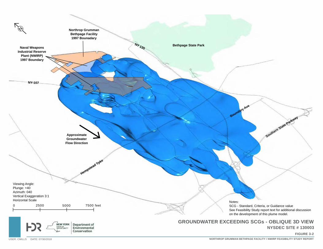
(MAP TITLE I)
(FIGURE #)
NYSDEC SITE #130003
(REPORT NAME)
GROUNDWATER EXCEEDING SCGs - OBLIQUE 3D VIEW
FIGURE 3-2
NYSDEC SITE # 130003
NORTHROP GRUMMAN BETHPAGE FACILITY / NWIRP FEASIBILITY STUDY REPORTUSER: CMILLS DATE: 07/30/2018
Northrop GrummanBethpage Facility1997 Bounadary
Bethpage State Park
Hempstead Tpke
SouthernState Parkway
NY 135
NY-107
Naval Weapons Industrial Reserve
Plant (NWIRP) 1997 Boundary
BoundaryAve
0 2500 5000 7500 feet
Viewing Angle:Plunge: +40Azimuth: 040Vertical Exaggeration 3:1Horizontal Scale
N
Approximate Groundwater
Flow Direction
Notes:SCG - Standard, Criteria, or Guidance valueSee Feasibility Study report text for additional discussionon the development of this plume model.
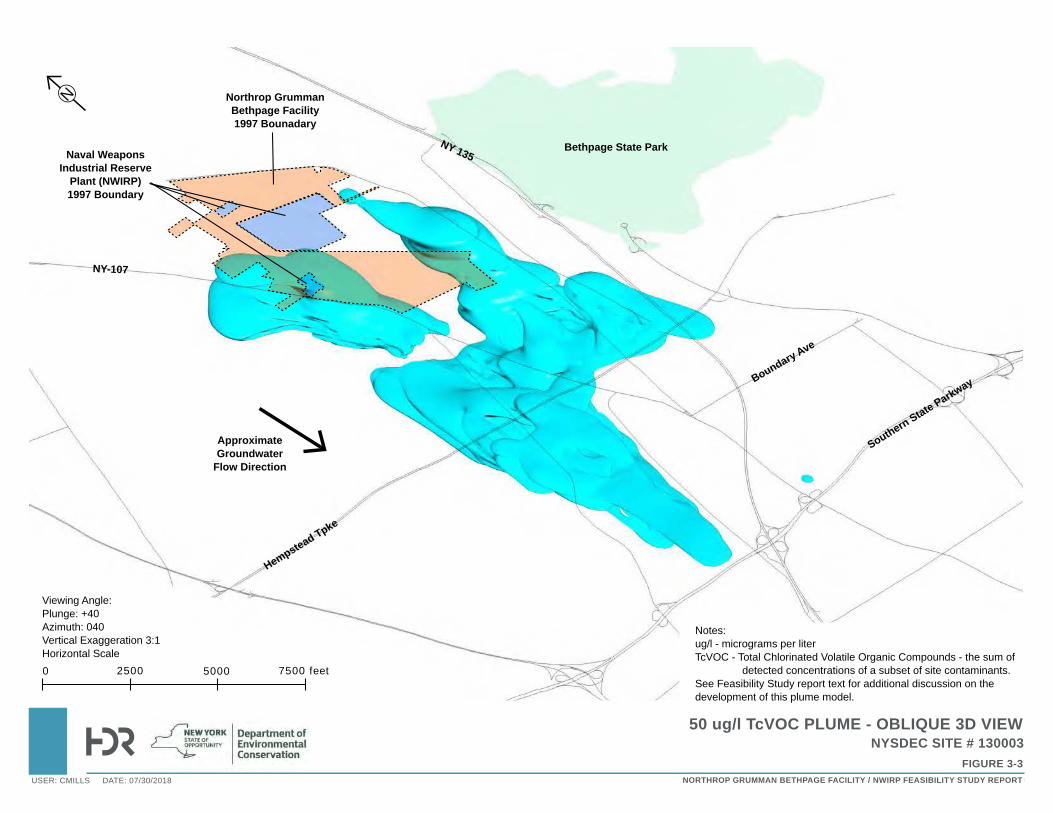
(MAP TITLE I)
(FIGURE #)
NYSDEC SITE #130003
(REPORT NAME)
50 ug/l TcVOC PLUME - OBLIQUE 3D VIEW
FIGURE 3-3
NYSDEC SITE # 130003
NORTHROP GRUMMAN BETHPAGE FACILITY / NWIRP FEASIBILITY STUDY REPORTUSER: CMILLS DATE: 07/30/2018
Northrop GrummanBethpage Facility1997 Bounadary
Bethpage State Park
Hempstead Tpke
Southern State Parkway
NY 135
NY-107
Naval Weapons Industrial Reserve
Plant (NWIRP) 1997 Boundary
Boundary Ave
0 2500 5000 7500 feet
Viewing Angle:Plunge: +40Azimuth: 040Vertical Exaggeration 3:1Horizontal Scale
N
Approximate Groundwater
Flow Direction
Notes:ug/l - micrograms per literTcVOC - Total Chlorinated Volatile Organic Compounds - the sum of detected concentrations of a subset of site contaminants.See Feasibility Study report text for additional discussion on the development of this plume model.
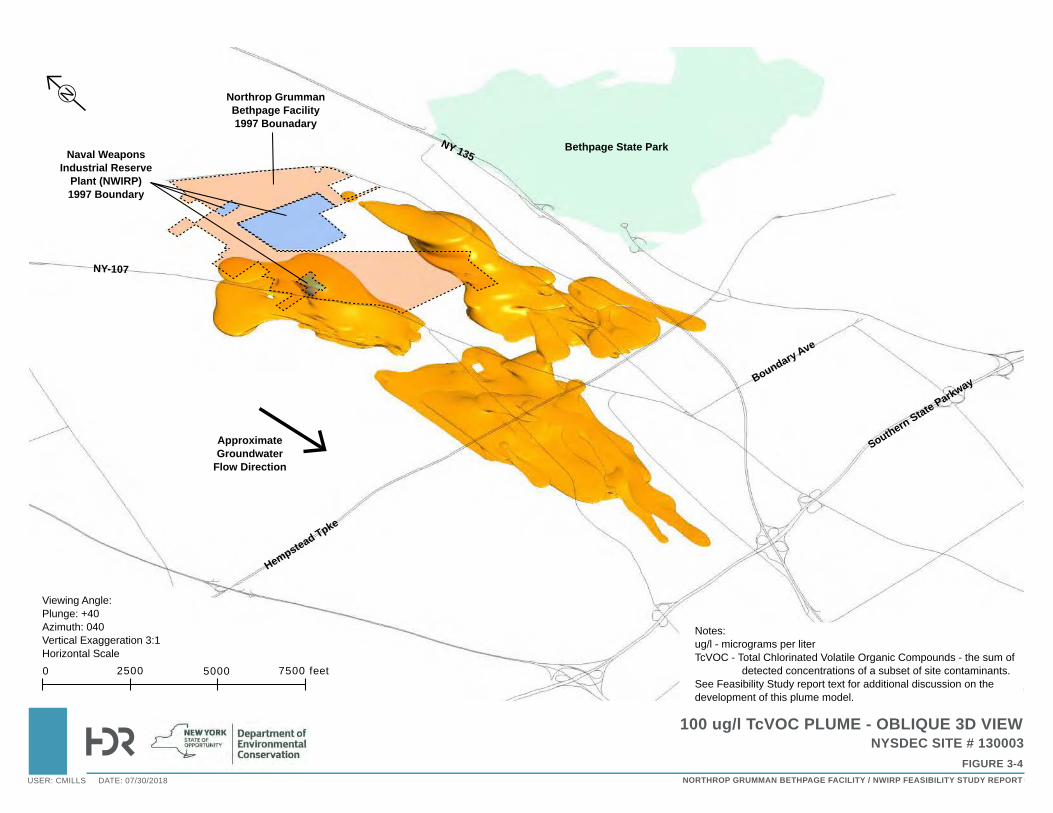
(MAP TITLE I)
(FIGURE #)
NYSDEC SITE #130003
(REPORT NAME)
100 ug/l TcVOC PLUME - OBLIQUE 3D VIEW
FIGURE 3-4
NYSDEC SITE # 130003
NORTHROP GRUMMAN BETHPAGE FACILITY / NWIRP FEASIBILITY STUDY REPORTUSER: CMILLS DATE: 07/30/2018
Northrop GrummanBethpage Facility1997 Bounadary
Bethpage State Park
Hempstead Tpke
Southern State Parkway
NY 135
NY-107
Naval Weapons Industrial Reserve
Plant (NWIRP) 1997 Boundary
Boundary Ave
0 2500 5000 7500 feet
Viewing Angle:Plunge: +40Azimuth: 040Vertical Exaggeration 3:1Horizontal Scale
N
Approximate Groundwater
Flow Direction
Notes:ug/l - micrograms per literTcVOC - Total Chlorinated Volatile Organic Compounds - the sum of detected concentrations of a subset of site contaminants.See Feasibility Study report text for additional discussion on the development of this plume model.
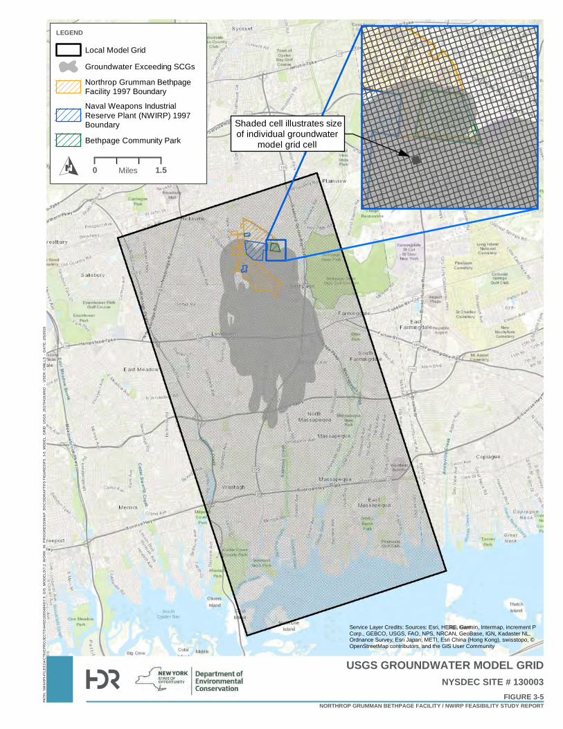
PATH
: \\MA
HPI-F
ILE01
\ACT
IVEPR
OJEC
TS\44
92\10
0548
40\7.
0_GI
S_MO
DELS
\7.2_
WOR
K_IN
_PRO
GRES
S\MA
P_DO
CS\D
RAFT
\FS FI
GURE
S\FS_
3-5_M
ODEL
_GRI
D_US
GS_2
0170
418.M
XD -
USE
R: C
MILL
S - D
ATE:
2/5/2
019
USGS GROUNDWATER MODEL GRID
FIGURE 3-5NYSDEC SITE # 130003
NORTHROP GRUMMAN BETHPAGE FACILITY / NWIRP FEASIBILITY STUDY REPORT
O
LEGEND
Local Model Grid
Groundwater Exceeding SCGs
Northrop Grumman BethpageFacility 1997 Boundary
Naval Weapons IndustrialReserve Plant (NWIRP) 1997Boundary
Bethpage Community Park
Service Layer Credits: Sources: Esri, HERE, Garmin, Intermap, increment PCorp., GEBCO, USGS, FAO, NPS, NRCAN, GeoBase, IGN, Kadaster NL,Ordnance Survey, Esri Japan, METI, Esri China (Hong Kong), swisstopo, ©OpenStreetMap contributors, and the GIS User Community
Shaded cell illustrates sizeof individual groundwater
model grid cell
0 1.5Miles
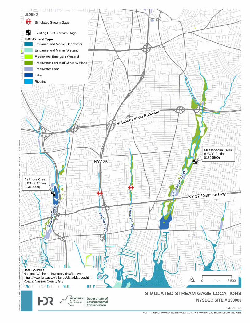
ED
EDED
ED Mas
sape
qua
Cree
k
SeafordC
reek
Bel lm
ore
Cre
ek
Seamans
Creek
Southern State Parkway
NY 27 / Sunrise Hwy
NY 135
Massapequa Creek(USGS Station01309500)
Bellmore Creek(USGS Station01310000)
PATH
: \\MA
HPI-F
ILE01
\ACT
IVEPR
OJEC
TS\44
92\10
0548
40\7.
0_GI
S_MO
DELS
\7.2_
WORK
_IN_P
ROGR
ESS\M
AP_D
OCS\D
RAFT
\FS FI
GURE
S\FS_
3-6_W
ETLA
ND_M
ONITO
RING
_LOC
ATIO
NS.M
XD -
USE
R: C
MILL
S -
DATE
: 1/9/
2019
FIGURE 3-6NYSDEC SITE # 130003
NORTHROP GRUMMAN BETHPAGE FACILITY / NWIRP FEASIBILITY STUDY REPORT
SIMULATED STREAM GAGE LOCATIONS
Data Sources:National Wetlands Inventory (NWI) Layer:https://www.fws.gov/wetlands/data/Mapper.htmlRoads: Nassau County GIS
LEGEND
ED Simulated Stream Gage
ED Existing USGS Stream Gage
NWI Wetland TypeEstuarine and Marine Deepwater
Estuarine and Marine Wetland
Freshwater Emergent Wetland
Freshwater Forested/Shrub Wetland
Freshwater Pond
Lake
Riverine
0 3,500FeetO
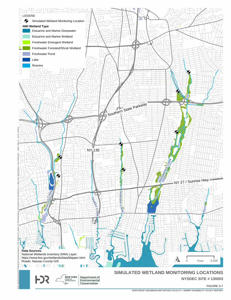
Mas
sape
qua
Cree
k
SeafordC
reek
Bel lm
ore
Cre
ek
Seamans
Creek
@A
@A
@A
@A
@A
@A
@A
Southern State Parkway
NY 27 / Sunrise Hwy
NY 135
PATH
: \\MA
HPI-F
ILE01
\ACT
IVEP
ROJE
CTS\
4492
\1005
4840
\7.0_
GIS_
MODE
LS\7.
2_W
ORK_
IN_P
ROGR
ESS\
MAP_
DOCS
\DRA
FT\FS
FIGU
RES\
FS_3
-7_W
ETLA
ND_M
ONITO
RING
_LOC
ATIO
NS.M
XD -
USE
R: C
MILL
S -
DATE
: 1/9/
2019
FIGURE 3-7NYSDEC SITE # 130003
NORTHROP GRUMMAN BETHPAGE FACILITY / NWIRP FEASIBILITY STUDY REPORT
SIMULATED WETLAND MONITORING LOCATIONS
Data Sources:National Wetlands Inventory (NWI) Layer:https://www.fws.gov/wetlands/data/Mapper.htmlRoads: Nassau County GIS
LEGEND@A Simulated Wetland Monitoring Location
NWI Wetland TypeEstuarine and Marine Deepwater
Estuarine and Marine Wetland
Freshwater Emergent Wetland
Freshwater Forested/Shrub Wetland
Freshwater Pond
Lake
Riverine
0 3,500FeetO
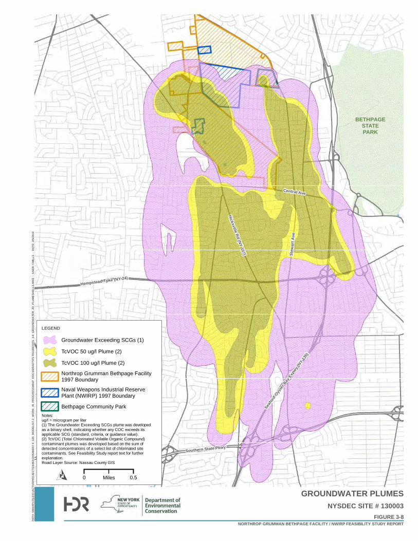
Hempstead Tpke (NY 24)
Hicksville Rd (NY 107)
Seafo
rd-Oyst
er Bay
Expw
y (NY 1
35)
Stew
art A
ve
Central Ave
Southern State Pkwy
BETHPAGESTATEPARK
PATH
: \\MA
HPI-F
ILE01
\ACT
IVEPR
OJEC
TS\44
92\10
0548
40\7.
0_GI
S_MO
DELS
\7.2_
WORK
_IN_P
ROGR
ESS\M
AP_D
OCS\D
RAFT
\FS FI
GURE
S\FS_
3-8_G
ROUN
DWAT
ER_2
D_PL
UMES
HELL
S.MXD
- U
SER:
CMI
LLS
- DAT
E: 2/
5/201
9
GROUNDWATER PLUMES
FIGURE 3-8NYSDEC SITE # 130003
NORTHROP GRUMMAN BETHPAGE FACILITY / NWIRP FEASIBILITY STUDY REPORT
LEGEND
Groundwater Exceeding SCGs (1)
TcVOC 50 ug/l Plume (2)
TcVOC 100 ug/l Plume (2)
Northrop Grumman Bethpage Facility1997 Boundary
Naval Weapons Industrial ReservePlant (NWIRP) 1997 Boundary
Bethpage Community Park
0 0.5MilesO
Notes:ug/l = microgram per liter(1) The Groundwater Exceeding SCGs plume was developedas a binary shell, indicating whether any COC exceeds itsapplicable SCG (standard, criteria, or guidance value).(2) TcVOC (Total Chlorinated Volatile Organic Compound)contaminant plumes was developed based on the sum ofdetected concentrations of a select list of chlorinated sitecontaminants. See Feasibility Study report text for furtherexplanation.Road Layer Source: Nassau County GIS
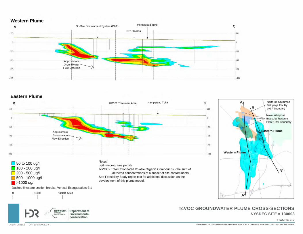
(MAP TITLE I)
(FIGURE #)
NYSDEC SITE #130003
(REPORT NAME)
TcVOC GROUNDWATER PLUME CROSS-SECTIONS
FIGURE 3-9
NYSDEC SITE # 130003
NORTHROP GRUMMAN BETHPAGE FACILITY / NWIRP FEASIBILITY STUDY REPORTUSER: CMILLS DATE: 07/30/2018
Eastern Plume
Western Plume
A
A'
B'
B
RE108 Area
Northrop Grumman Bethpage Facility 1997 Boundary
Naval WeaponsIndustrial ReservePlant 1997 Boundary
0 2500 5000 feet
Dashed lines are section breaks; Vertical Exaggeration: 3:1
50 to 100 ug/l100 - 200 ug/l200 - 500 ug/l500 - 1000 ug/l>1000 ug/l
Approximate Groundwater Flow Direction
Approximate Groundwater Flow Direction
RW-21 Treatment Area Hempstead Tpke
Hempstead TpkeOn-Site Containment System (OU2)
Western Plume
Eastern Plume
Notes:ug/l - micrograms per literTcVOC - Total Chlorinated Volatile Organic Compounds - the sum of detected concentrations of a subset of site contaminants.See Feasibility Study report text for additional discussion on the development of this plume model.
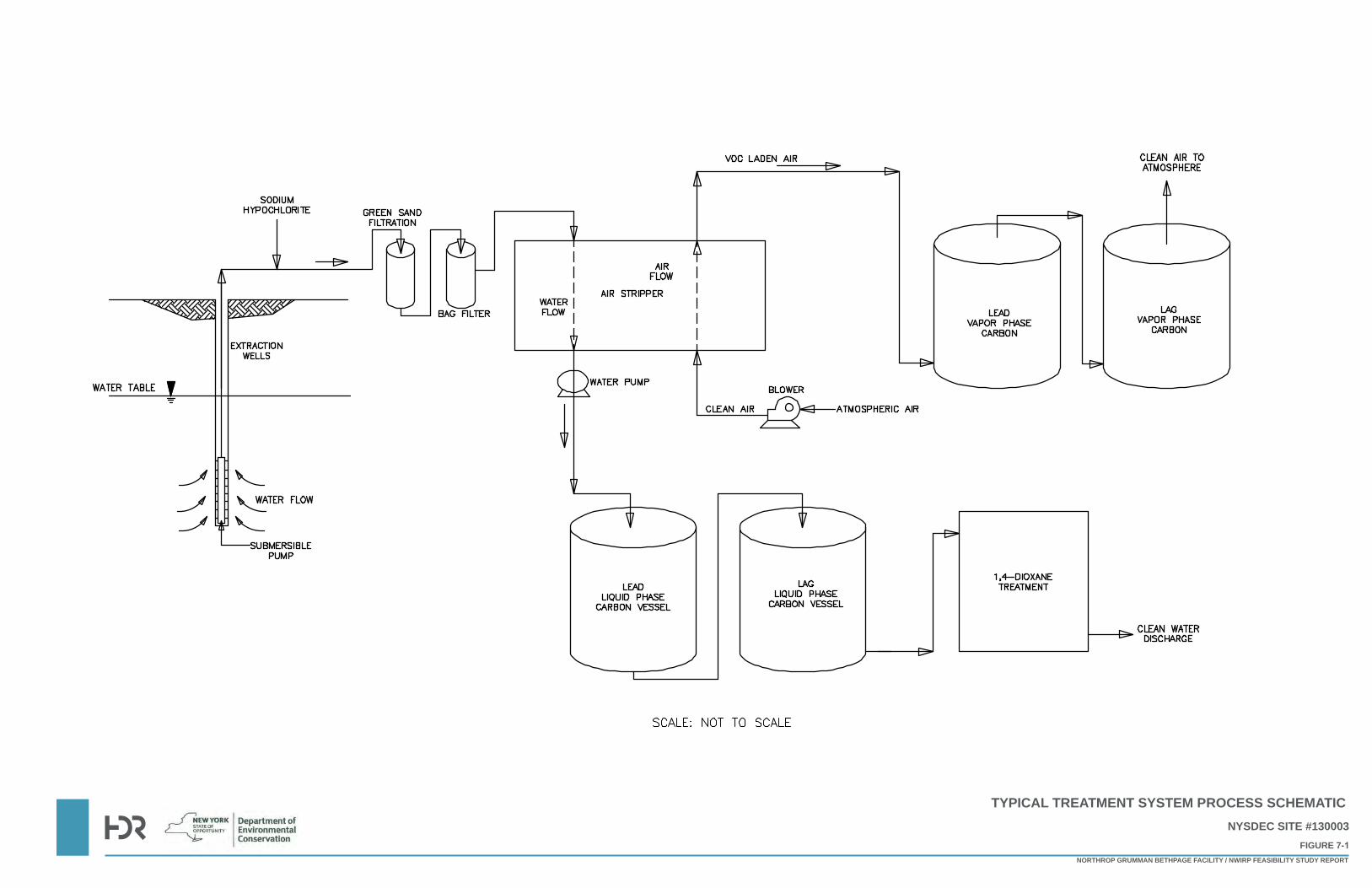
TYPICAL TREATMENT SYSTEM PROCESS SCHEMATIC NYSDEC SITE #130003
FIGURE 7-1NORTHROP GRUMMAN BETHPAGE FACILITY / NWIRP FEASIBILITY STUDY REPORT
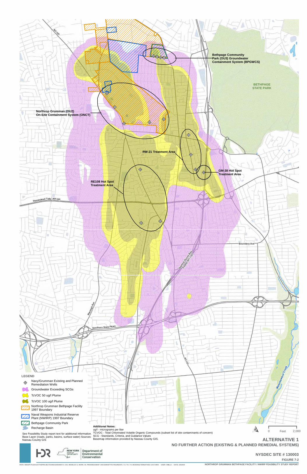
@?
@?@?
@?@?
@?
@?
@?
@?
@? @?@?
@?@?@?
@?
Bethpage Community Park (OU3) Groundwater Containment System (BPGWCS)
RW-21 Treatment Area
GM-38 Hot Spot Treatment Area
RE108 Hot SpotTreatment Area
Northrop Grumman (OU2)On-Site Containment System (ONCT)
BETHPAGESTATE PARK
PATH: \\MAHPI-FILE01\ACTIVEPROJECTS\4492\10054840\7.0_GIS_MODELS\7.2_WORK_IN_PROGRESS\MAP_DOCS\DRAFT\FS FIGURES\FS_7-2_TO_7-9_DESIGNALTERNATIVES 11X17.MXD - USER: CMILLS - DATE: 2/5/2019
FIGURE 7-2NYSDEC SITE # 130003
NORTHROP GRUMMAN BETHPAGE FACILITY / NWIRP FEASIBILITY STUDY REPORT
LEGEND
@?Navy/Grumman Existing and PlannedRemediation WellsGroundwater Exceeding SCGs
TcVOC 50 ug/l Plume
TcVOC 100 ug/l PlumeNorthrop Grumman Bethpage Facility1997 BoundaryNaval Weapons Industrial ReservePlant (NWIRP) 1997 BoundaryBethpage Community ParkRecharge Basin
0 2,000FeetO
NO FURTHER ACTION (EXISTING & PLANNED REMEDIAL SYSTEMS)
Additional Notes:ug/l - micrograms per literTCVOC - Total Chlorinated Volatile Organic Compounds (subset list of site contaminants of concern)SCG - Standards, Criteria, and Guidance ValuesBasemap information provided by Nassau County GIS.
See Feasibility Study report text for additional information.Base Layer (roads, parks, basins, surface water) Sources:Nassau County GIS ALTERNATIVE 1
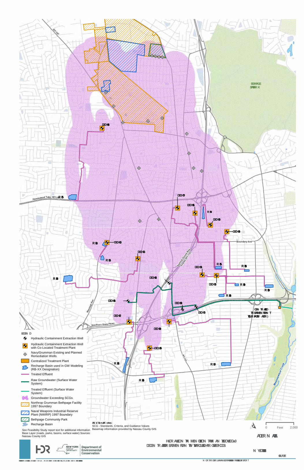
@?
@?@?
@?@?
@?
@?
@?
@?
@? @?@?
@?@?@?
@?
")@A
")@A
@A
")@A
")@A
")@A
@A
")@A
@A@A
")@A")@A
")@A")@A
")@A")@A
RB-01
RB-02
RB-03
RB-04
RB-05
RB-06
RB-07
RB-08RB-09
RB-10
RB-11 RB-12
RB-13
DECHC-02
DECHC-03
DECHC-04
DECHC-05
DECHC-06
DECHC-07
DECHC-08
DECHC-09
DECHC-10
DECHC-11
DECHC-12
DECHC-13
DECHC-14
DECHC-15
DECHC-16
DECHC-17
CEN TRALIZED TREATMEN T PLAN T(TO SURFACE W ATER)
BETHPAGESTATE PARK
PATH: \\MAHPI-FILE01\ACTIVEPROJECTS\4492\10054840\7.0_GIS_MODELS\7.2_ W ORK_IN _ PROGRESS\MAP_ DOCS\DRAFT\FS FIGURES\FS_7-2_TO_7-9_DESIGN ALTER N ATIVES 11X 17.MX D - USER: CMILLS - DATE: 2/5/2019
FIGURE 7-3N YSDEC SITE # 130003
N ORTHROP GRUMMAN BETHPAGE FACILITY / N W IRP FEASIBILITY STUDY REPORT
LEGEN D@A Hydraulic Containment Extraction Well
")@AHydraulic Containment Extraction Wellwith Co-Located Treatment Plant
@?Navy/Grumman Existing and PlannedRemediation WellsCentralized Treatment PlantRecharge Basin used in GW Modeling(RB-XX Designation)Treated Effluent
Raw Groundwater (Surface WaterSystem)
Treated Effluent (Surface WaterSystem)Groundwater Exceeding SCGsNorthrop Grumman Bethpage Facility1997 BoundaryNaval Weapons Industrial ReservePlant (NWIRP) 1997 BoundaryBethpage Community ParkRecharge Basin
0 2,000FeetO
HYDRAULIC CON TAIN MEN T OF SITE CON TAMIN AN TS ABOVE SCGs – DECEN TRALIZED TREATMEN T PLAN TS W ITH VARIOUS DISCHARGE METHODS
Ad d itiona l N otes:SCG - Standards, Criteria, and Guidance ValuesBasemap information provided by Nassau County GIS.See Feasibility Study report text for additional information.
Base Layer (roads, parks, basins, surface water) Sources:Nassau County GIS ALTER N ATIVE 2A
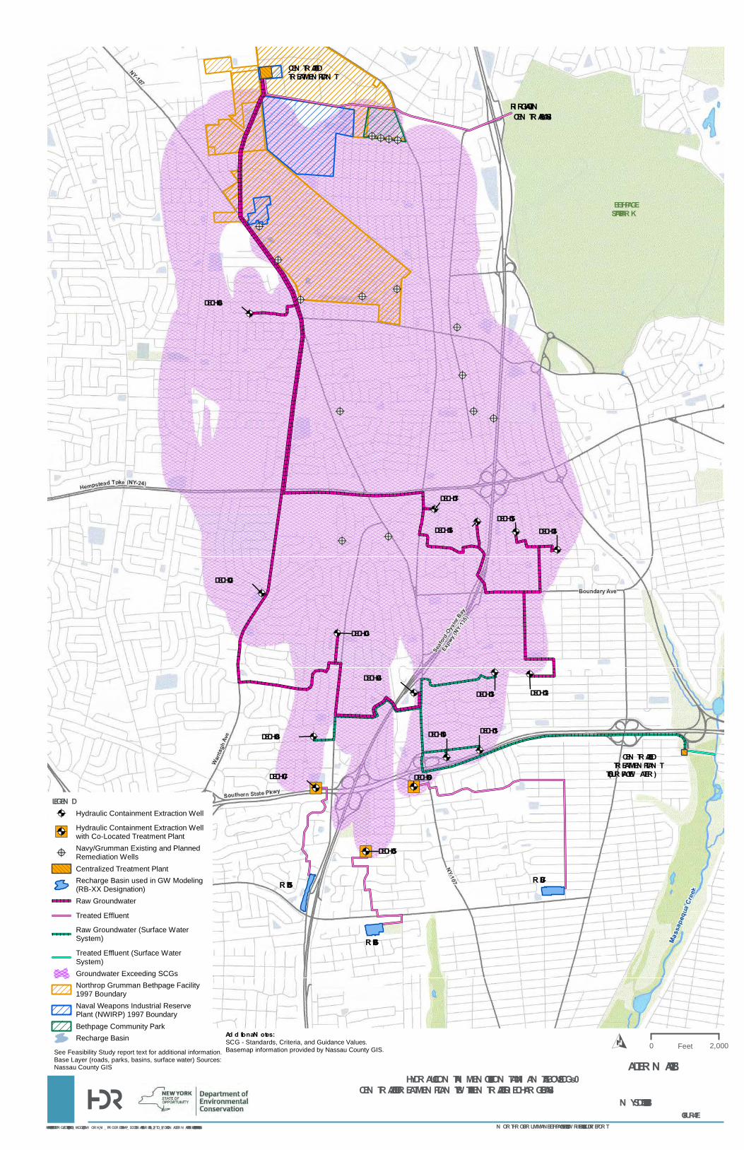
@?
@?@?
@?@?
@?
@?
@?
@?
@? @?@?
@?@?@?
@?
@A
@A
@A
")@A
@A
")@A
@A
")@A
@A@A
@A@A
@A
@A
@A
@A
IRRIGATION
RB-05
RB-06
RB-07
CEN TRAL BASIN
DECHC-02
DECHC-03
DECHC-04
DECHC-05
DECHC-06
DECHC-07
DECHC-08
DECHC-09
DECHC-10 DECHC-11
DECHC-12DECHC-13
DECHC-14DECHC-15
DECHC-16
DECHC-17
CEN TRALIZED TREATMEN T PLAN T
CEN TRALIZED TREATMEN T PLAN T(TO SURFACE W ATER)
BETHPAGESTATE PARK
PATH: \\MAHPI-FILE01\ACTIVEPROJECTS\4492\10054840\7.0_GIS_MODELS\7.2_ W ORK_IN _ PROGRESS\MAP_ DOCS\DRAFT\FS FIGURES\FS_7-2_TO_7-9_DESIGN ALTER N ATIVES 11X 17.MX D - USER: CMILLS - DATE: 2/5/2019
FIGURE 7-4N YSDEC SITE # 130003
N ORTHROP GRUMMAN BETHPAGE FACILITY / N W IRP FEASIBILITY STUDY REPORT
LEGEN D@A Hydraulic Containment Extraction Well
")@AHydraulic Containment Extraction Wellwith Co-Located Treatment Plant
@?Navy/Grumman Existing and PlannedRemediation WellsCentralized Treatment PlantRecharge Basin used in GW Modeling(RB-XX Designation)Raw Groundwater
Treated Effluent
Raw Groundwater (Surface WaterSystem)
Treated Effluent (Surface WaterSystem)Groundwater Exceeding SCGsNorthrop Grumman Bethpage Facility1997 BoundaryNaval Weapons Industrial ReservePlant (NWIRP) 1997 BoundaryBethpage Community ParkRecharge Basin
0 2,000FeetO
HYDRAULIC CON TAIN MEN T OF SITE CON TAMIN AN TS ABOVE SCGs – CEN TRALIZED TREATMEN T PLAN TS W ITH A CEN TRALIZED RECHARGE BASIN
Ad d itiona l N otes:SCG - Standards, Criteria, and Guidance Values.Basemap information provided by Nassau County GIS.See Feasibility Study report text for additional information.
Base Layer (roads, parks, basins, surface water) Sources:Nassau County GIS ALTER N ATIVE 2B
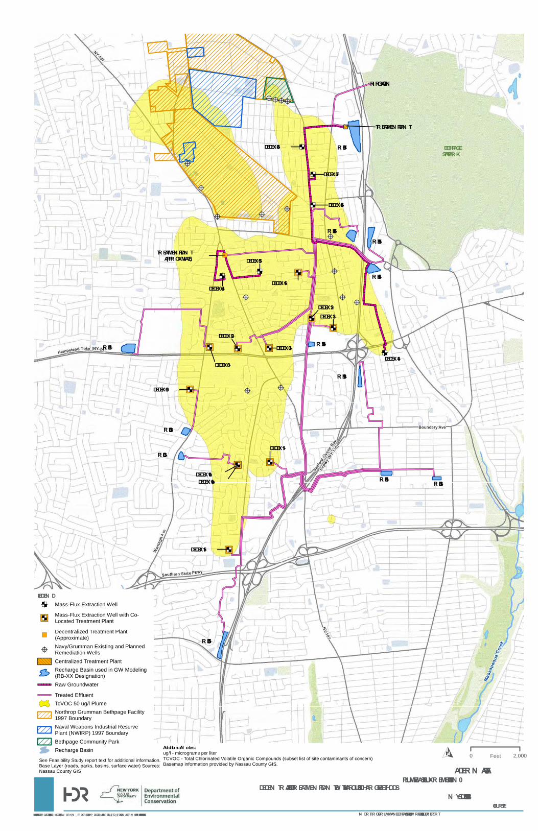
@?
@?@?
@?@?
@?
@?
@?
@?
@? @?@?
@?@?@?
@?
")ED ")ED ")ED
EDED
ED
ED
ED
")ED
")ED")ED ")ED
")ED")ED
ED
")ED
")ED
")
IRRIGATION
RB-01
RB-02
RB-03
RB-05
RB-11 RB-12
RB-13
RB-14
RB-15RB-16
RB-17
RB-18
DECEX -01
DECEX -02DECEX -03
DECEX -04
DECEX -05
DECEX -06
DECEX -07
DECEX -08
DECEX -09
DECEX -10aDECEX -10b
DECEX -11
DECEX -12DECEX -13
DECEX -14
DECEX -15
DECEX -16
TREATMEN T PLAN T(APPROX IMATE)
TREATMEN T PLAN T
BETHPAGESTATE PARK
PATH: \\MAHPI-FILE01\ACTIVEPROJECTS\4492\10054840\7.0_GIS_MODELS\7.2_ W ORK_IN _ PROGRESS\MAP_ DOCS\DRAFT\FS FIGURES\FS_7-2_TO_7-9_DESIGN ALTER N ATIVES 11X 17.MX D - USER: CMILLS - DATE: 2/5/2019
FIGURE 7-5N YSDEC SITE # 130003
N ORTHROP GRUMMAN BETHPAGE FACILITY / N W IRP FEASIBILITY STUDY REPORT
LEGEN DED Mass-Flux Extraction Well
")EDMass-Flux Extraction Well with Co-Located Treatment Plant
")Decentralized Treatment Plant(Approximate)
@?Navy/Grumman Existing and PlannedRemediation WellsCentralized Treatment PlantRecharge Basin used in GW Modeling(RB-XX Designation)Raw Groundwater
Treated EffluentTcVOC 50 ug/l PlumeNorthrop Grumman Bethpage Facility1997 BoundaryNaval Weapons Industrial ReservePlant (NWIRP) 1997 BoundaryBethpage Community ParkRecharge Basin
0 2,000FeetO
PLUME MASS FLUX REMEDIATION – DECEN TRALIZED TREATMEN T PLAN TS W ITH VARIOUS DISCHARGE METHODS
Additiona l N otes:ug/l - micrograms per literTCVOC - Total Chlorinated Volatile Organic Compounds (subset list of site contaminants of concern)Basemap information provided by Nassau County GIS.
See Feasibility Study report text for additional information.Base Layer (roads, parks, basins, surface water) Sources:Nassau County GIS ALTER N ATIVE 3A
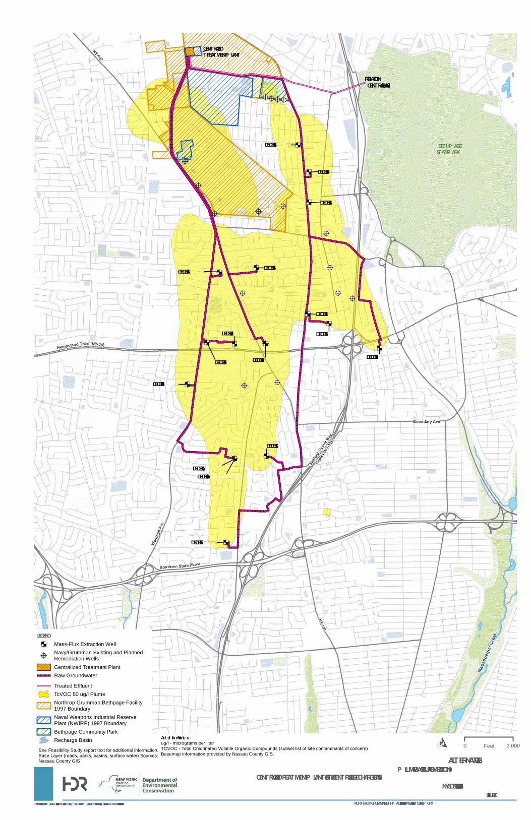
@?
@?@?
@?@?
@?
@?
@?
@?
@? @?@?
@?@?@?
@?
ED ED ED
EDED
ED
ED
ED
ED
EDED ED
ED
ED
ED
ED
IRRIGATIONCENTRAL BASIN
DECEX-01
DECEX-02
DECEX-03
DECEX-04 DECEX-05
DECEX-06
DECEX-07
DECEX-08
DECEX-09
DECEX-10aDECEX-10b
DECEX-11
DECEX-12
DECEX-13
DECEX-14
DECEX-15
CENTRALIZED TREATMENT P LANT
BETHP AGESTATE P ARK
PATH: \\MAHP I-FILE01\ACTIVEP ROJECTS\4492\10054840\7.0_GIS_MODELS\7.2_WORK_IN_P ROGRESS\MAP _DOCS\DRAFT\FS FIGURES\FS_7-2_TO_7-9_DESIGNALTERNATIVES 11X17.MXD - USER: CMILLS - DATE: 2/5/2019
FIGURE 7-6NYSDEC SITE # 130003
NORTHROP GRUMMAN BETHP AGE FACILITY / NWIRP FEASIBILITY STUDY REP ORT
LEGENDED Mass-Flux Extraction Well
@?Navy/Grumman Existing and PlannedRemediation WellsCentralized Treatment PlantRaw Groundwater
Treated EffluentTcVOC 50 ug/l PlumeNorthrop Grumman Bethpage Facility1997 BoundaryNaval Weapons Industrial ReservePlant (NWIRP) 1997 BoundaryBethpage Community ParkRecharge Basin
0 2,000FeetO
P LUME MASS FLUX REMEDIATION – CENTRALIZED TREATMENT P LANTS WITH A CENTRALIZED RECHARGE BASIN
Ad d itional Note s:ug/l - micrograms per literTCVOC - Total Chlorinated Volatile Organic Compounds (subset list of site contaminants of concern)Basemap information provided by Nassau County GIS.
See Feasibility Study report text for additional information.Base Layer (roads, parks, basins, surface water) Sources:Nassau County GIS ALTERNATIVE 3B
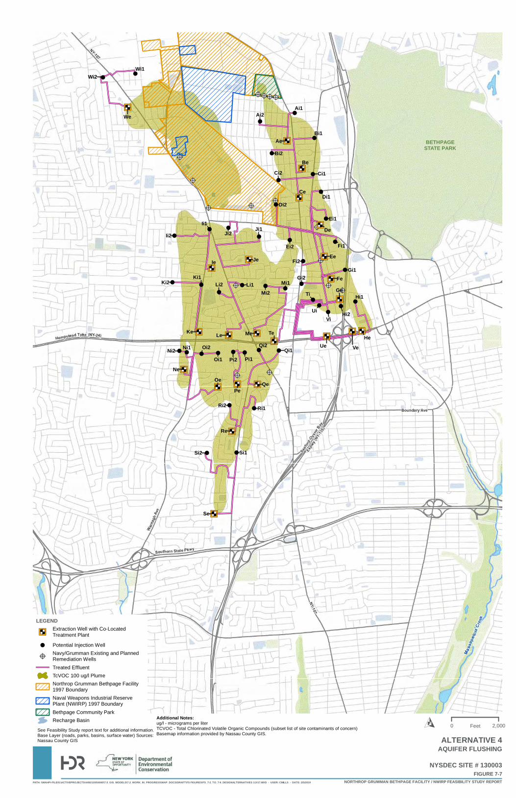
@?
@?@?
@?@?
@?
@?
@?
@?
@? @?@?
@?@?@?
@?
")ED
")ED
")ED
")ED
")ED")ED
")ED
")ED
")ED")ED")ED")ED
")ED
")ED
")ED ")ED ")ED
")ED
")ED
")ED
")ED")ED
")ED
!
!!
!
!
!
!
!
!
!!
!!
!
!
!
!
!!
!!
!!
!
!!!!!!!!
!!
!!
!
!
!
!
!
!!
Be
Ce
De
Ee
Fe
Ie Je
Ge
HeVeUe
Me Te
NeOe
PeQe
Re
Se
Ae
LeKe
We
Bi2
Ci1Ci2
Di1Di2
Ei1
Fi1
Gi1Gi2
Ei2
Ji1Ji2Ii1
Ki1Li2 Li1
Fi2
Mi1Mi2 Ti
UiVi
Hi2
Hi1
Qi1Qi2
Pi1Pi2Oi1Oi2Ni1Ni2
Ri1Ri2
Si1Si2
Ii2
Ki2
Ai2Ai1
Bi1
Wi1Wi2
BETHPAGESTATE PARK
PATH: \\MAHPI-FILE01\ACTIVEPROJECTS\4492\10054840\7.0_GIS_MODELS\7.2_WORK_IN_PROGRESS\MAP_DOCS\DRAFT\FS FIGURES\FS_7-2_TO_7-9_DESIGNALTERNATIVES 11X17.MXD - USER: CMILLS - DATE: 2/5/2019
FIGURE 7-7NYSDEC SITE # 130003
NORTHROP GRUMMAN BETHPAGE FACILITY / NWIRP FEASIBILITY STUDY REPORT
LEGEND
")EDExtraction Well with Co-LocatedTreatment Plant
! Potential Injection Well
@?Navy/Grumman Existing and PlannedRemediation WellsTreated EffluentTcVOC 100 ug/l PlumeNorthrop Grumman Bethpage Facility1997 BoundaryNaval Weapons Industrial ReservePlant (NWIRP) 1997 BoundaryBethpage Community ParkRecharge Basin
0 2,000FeetO
AQUIFER FLUSHING
Additional Notes:ug/l - micrograms per literTCVOC - Total Chlorinated Volatile Organic Compounds (subset list of site contaminants of concern)Basemap information provided by Nassau County GIS.
See Feasibility Study report text for additional information.Base Layer (roads, parks, basins, surface water) Sources:Nassau County GIS ALTERNATIVE 4
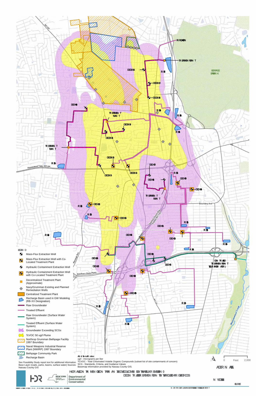
@?
@?@?
@?@?
@?
@?
@?
@?
@? @?@?
@?@?@?
@?
ED ")ED ")ED
EDED
ED
ED
ED
")@A
")@A
")@A
")@A
@A
")@A
@A
")@A
@A@A
")@A")@A
")@A")@A
@A
@A
")
")
")
IRRIGATION
RB-01
RB-02
RB-03
RB-04
RB-05
RB-06
RB-07
RB-08RB-09
RB-11
RB-12
RB-13
RB-14
RB-15RB-16
RB-17
DECEX -01
DECEX -02
DECEX -03
DECEX -04
DECEX -05
DECEX -06
DECEX -07
DECEX -08
DECHC-02
DECHC-03
DECHC-04
DECHC-05
DECHC-06
DECHC-07
DECHC-08
DECHC-09
DECHC-10
DECHC-11
DECHC-12
DECHC-13
DECHC-14
DECHC-15DECHC-16
DECHC-17
TREATMEN T PLAN T
TREATMEN T PLAN T
TREATMEN T PLAN T
CEN TRALIZED TREATMEN T PLAN T(TO SURFACE W ATER)
TREATMEN T PLAN T
BETHPAGESTATE PARK
PATH: \\MAHPI-FILE01\ACTIVEPROJECTS\4492\10054840\7.0_GIS_MODELS\7.2_ W ORK_IN _ PROGRESS\MAP_ DOCS\DRAFT\FS FIGURES\FS_7-2_TO_7-9_DESIGN ALTER N ATIVES 11X 17.MX D - USER: CMILLS - DATE: 2/5/2019
FIGURE 7-8N YSDEC SITE # 130003
N ORTHROP GRUMMAN BETHPAGE FACILITY / N W IRP FEASIBILITY STUDY REPORT
LEGEN DED Mass-Flux Extraction Well
")EDMass-Flux Extraction Well with Co-Located Treatment Plant
@A Hydraulic Containment Extraction Well
")@AHydraulic Containment Extraction Wellwith Co-Located Treatment Plant
")Decentralized Treatment Plant(Approximate)
@?Navy/Grumman Existing and PlannedRemediation WellsCentralized Treatment PlantRecharge Basin used in GW Modeling(RB-XX Designation)Raw Groundwater
Treated Effluent
Raw Groundwater (Surface WaterSystem)
Treated Effluent (Surface WaterSystem)Groundwater Exceeding SCGs
TcVOC 50 ug/l PlumeNorthrop Grumman Bethpage Facility1997 BoundaryNaval Weapons Industrial ReservePlant (NWIRP) 1997 BoundaryBethpage Community ParkRecharge Basin
0 2,000FeetO
HYDRAULIC CON TAIN MEN T OF SITE CON TAMIN AN TS ABOVE SCGs COMBIN ED W ITH MASS FLUX REMEDIATION – DECEN TRALIZED TREATMEN T PLAN TS W ITH VARIOUS DISCHARGE METHODS
Ad d itiona l N otes:ug/l - micrograms per literTCVOC - Total Chlorinated Volatile Organic Compounds (subset list of site contaminants of concern)SCG - Standards, Criteria, and Guidance ValuesBasemap information provided by Nassau County GIS.
See Feasibility Study report text for additional information.Base Layer (roads, parks, basins, surface water) Sources:Nassau County GIS ALTER N ATIVE 5A
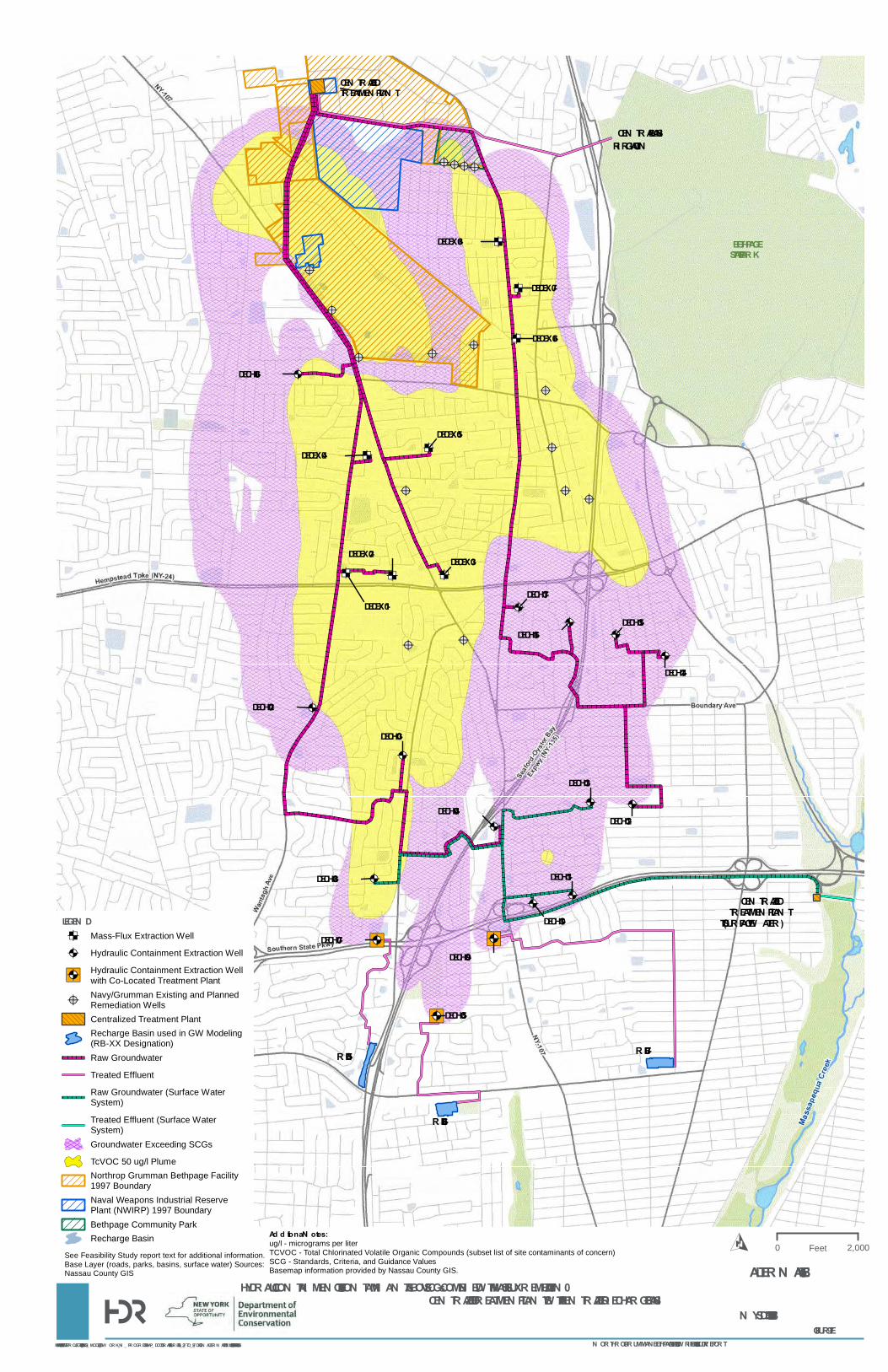
@?
@?@?
@?@?
@?
@?
@?
@?
@? @?@?
@?@?@?
@?
ED ED ED
EDED
ED
ED
ED
@A
@A
@A
")@A
@A
")@A
@A
")@A
@A@A
@A@A
@A
@A
@A
@A
CEN TRALIZED TREATMEN T PLAN T(TO SURFACE W ATER)
CEN TRAL BASINIRRIGATION
RB-05
RB-06
RB-07
DECEX -01
DECEX -02 DECEX -03
DECEX -04DECEX -05
DECEX -06
DECEX -07
DECEX -08
DECHC-02
DECHC-03
DECHC-04
DECHC-05
DECHC-06
DECHC-07
DECHC-08
DECHC-09
DECHC-10
DECHC-11
DECHC-12
DECHC-13
DECHC-14
DECHC-15DECHC-16
DECHC-17
CEN TRALIZED TREATMEN T PLAN T
BETHPAGESTATE PARK
PATH: \\MAHPI-FILE01\ACTIVEPROJECTS\4492\10054840\7.0_GIS_MODELS\7.2_ W ORK_IN _ PROGRESS\MAP_ DOCS\DRAFT\FS FIGURES\FS_7-2_TO_7-9_DESIGN ALTER N ATIVES 11X 17.MX D - USER: CMILLS - DATE: 2/5/2019
FIGURE 7-9N YSDEC SITE # 130003
N ORTHROP GRUMMAN BETHPAGE FACILITY / N W IRP FEASIBILITY STUDY REPORT
LEGEN DED Mass-Flux Extraction Well
@A Hydraulic Containment Extraction Well
")@AHydraulic Containment Extraction Wellwith Co-Located Treatment Plant
@?Navy/Grumman Existing and PlannedRemediation WellsCentralized Treatment PlantRecharge Basin used in GW Modeling(RB-XX Designation)Raw Groundwater
Treated Effluent
Raw Groundwater (Surface WaterSystem)
Treated Effluent (Surface WaterSystem)Groundwater Exceeding SCGs
TcVOC 50 ug/l PlumeNorthrop Grumman Bethpage Facility1997 BoundaryNaval Weapons Industrial ReservePlant (NWIRP) 1997 BoundaryBethpage Community ParkRecharge Basin
0 2,000FeetO
HYDRAULIC CON TAIN MEN T OF SITE CON TAMIN AN TS ABOVE SCGs COMBIN ED W ITH MASS FLUX REMEDIATION – CEN TRALIZED TREATMEN T PLAN TS W ITH A CEN TRALIZED RECHARGE BASIN
Ad d itiona l N otes:ug/l - micrograms per literTCVOC - Total Chlorinated Volatile Organic Compounds (subset list of site contaminants of concern)SCG - Standards, Criteria, and Guidance ValuesBasemap information provided by Nassau County GIS.
See Feasibility Study report text for additional information.Base Layer (roads, parks, basins, surface water) Sources:Nassau County GIS ALTER N ATIVE 5B
Northrop Grumman – Bethpage Facility/Naval Weapons Industrial Reserve Plant Feasibility Study Report April 2019
APPENDIX A
Breakdown of Costs for Groundwater Remedial Alternatives
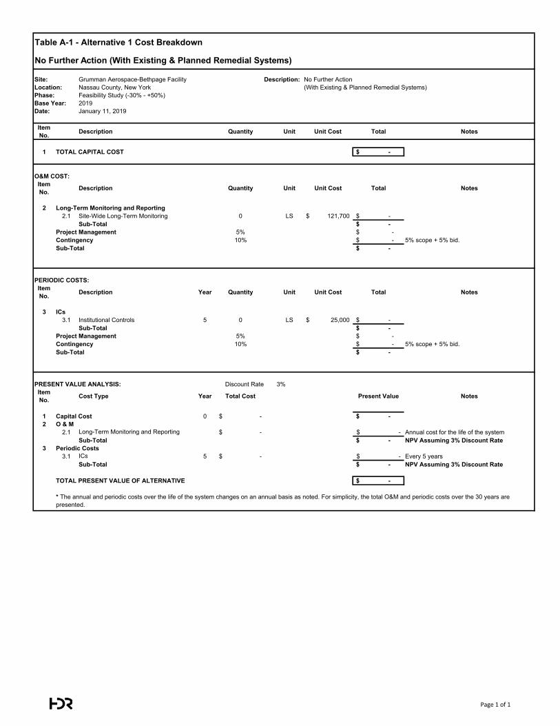
Table A-1 - Alternative 1 Cost Breakdown
No Further Action (With Existing & Planned Remedial Systems)
Site: Grumman Aerospace-Bethpage Facility Description: Location: Nassau County, New YorkPhase: Feasibility Study (-30% - +50%)Base Year: 2019Date: January 11, 2019
Item No. Description Quantity Unit Unit Cost Total Notes
1 TOTAL CAPITAL COST -$
O&M COST:Item No. Description Quantity Unit Unit Cost Total Notes
2 Long-Term Monitoring and Reporting2.1 Site-Wide Long-Term Monitoring 0 LS 121,700$ -$
Sub-Total -$ Project Management 5% -$ Contingency 10% -$ 5% scope + 5% bid.Sub-Total -$
PERIODIC COSTS:Item No. Description Year Quantity Unit Unit Cost Total Notes
3 ICs3.1 Institutional Controls 5 0 LS 25,000$ -$
Sub-Total -$ Project Management 5% -$ Contingency 10% -$ 5% scope + 5% bid.Sub-Total -$
PRESENT VALUE ANALYSIS: Discount Rate 3% Interest Rate: 0%Item No. Cost Type Year Total Cost Present Value Notes
1 Capital Cost 0 -$ -$ 2 O & M
2.1 Long-Term Monitoring and Reporting -$ -$ Annual cost for the life of the systemSub-Total -$ NPV Assuming 3% Discount Rate
3 Periodic Costs3.1 ICs 5 -$ -$ Every 5 years
Sub-Total -$ NPV Assuming 3% Discount Rate
TOTAL PRESENT VALUE OF ALTERNATIVE -$
No Further Action (With Existing & Planned Remedial Systems)
* The annual and periodic costs over the life of the system changes on an annual basis as noted. For simplicity, the total O&M and periodic costs over the 30 years are presented.
Page 1 of 1
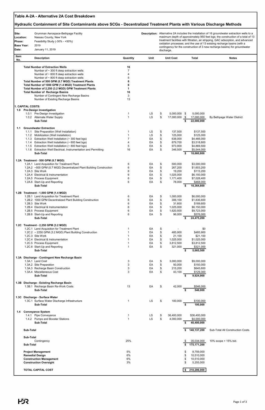
Table A-2A - Alternative 2A Cost Breakdown
Hydraulic Containment of Site Contaminants above SCGs - Decentralized Treatment Plants with Various Discharge Methods
Site: Grumman Aerospace-Bethpage Facility Description: Location: Nassau County, New YorkPhase: Feasibility Study (-30% - +50%)Base Year: 2019Date: January 11, 2019
Item No. Description Quantity Unit Unit Cost Total Notes
Total Number of Extraction Wells 16Number of ~ 300 ft deep extraction wells 7Number of ~ 600 ft deep extraction wells 4Number of ~ 800 ft deep extraction wells 5
Total Number of 500 GPM (0.7 MGD) Treatment Plants 6Total Number of 1000 GPM (1.4 MGD) Treatment Plants 6Total Number of 2,250 (3.2 MGD) GPM Treatment Plants 1Total Number of Recharge Basins 16
Number of Contingent New Recharge Basins 3Number of Existing Recharge Basins 13
1. CAPITAL COSTS:1.0 Pre-Design Investigation
1.0.1 Pre-Design Investigation 1 LS 5,000,000$ 5,000,000$ 1.0.2 Alternate Water Supply 1 LS 17,000,000$ 17,000,000$ By Bethpage Water District
Sub-Total 22,000,000$
1.1 Groundwater Extraction1.1.1 Site Preparation (Well Installation) 1 LS 137,500$ $137,5001.1.2 Mobilization (Well Installation) 1 LS 125,000$ $125,0001.1.3 Extraction Well Installation (~ 300 feet bgs) 7 EA 638,000$ $4,466,0001.1.4 Extraction Well Installation (~ 600 feet bgs) 4 EA 879,700$ $3,518,8001.1.5 Extraction Well Installation (~ 800 feet bgs) 5 EA 973,900$ $4,869,5001.1.6 Extraction Well Electrical, Instrumentation and Permitting 16 EA 346,500$ $5,544,000
Sub-Total 18,660,800$
1.2A Treatment - 500 GPM (0.7 MGD)1.2A.1 Land Acquisition for Treatment Plant 6 EA 500,000$ $3,000,0001.2A.2 ~500 GPM (0.7 MGD) Decentralized Plant Building Construction 6 EA 267,200$ $1,603,2001.2A.3 Site Work 6 EA 19,200$ $115,2001.2A.4 Electrical & Instrumentation 6 EA 1,025,000$ $6,150,0001.2A.5 Process Equipment 6 EA 1,171,400$ $7,028,4001.2A.6 Start-Up and Reporting 6 EA 78,000$ $468,000
Sub-Total 18,364,800$
1.2B Treatment - 1,000 GPM (1.4 MGD)1.2B.1 Land Acquisition for Treatment Plant 6 EA 1,000,000$ $6,000,0001.2B.2 1000 GPM Decentralized Plant Building Construction 6 EA 306,100$ $1,836,6001.2B.3 Site Work 6 EA 31,600$ $189,6001.2B.4 Electrical & Instrumentation 6 EA 1,025,000$ $6,150,0001.2B.5 Process Equipment 6 EA 1,620,500$ $9,723,0001.2B.6 Start-Up and Reporting 6 EA 96,000$ $576,000
Sub-Total 24,475,200$
1.2C Treatment - 2,250 GPM (3.2 MGD)1.2C.1 Land Acquisition for Treatment Plant 1 EA -$ $01.2C.2 ~ 2250 GPM (3.2 MGD) Plant Building Construction 1 EA 485,900$ $485,9001.2C.3 Site Work 1 EA 21,100$ $21,1001.2C.4 Electrical & Instrumentation 1 EA 1,025,000$ $1,025,0001.2C.5 Process Equipment 1 EA 3,812,500$ $3,812,5001.2C.6 Start-Up and Reporting 1 EA 321,000$ $321,000
Sub-Total 5,665,500$
1.3A Discharge - Contingent New Recharge Basin1.3A.1 Land Cost 3 EA 3,000,000$ $9,000,0001.3A.2 Site Preparation 3 EA 50,000$ $150,0001.3A.3 Recharge Basin Construction 3 EA 215,200$ $645,6001.3A.4 Miscellaneous Cost 3 EA 43,100$ $129,300
Sub-Total 9,924,900$
1.3B Discharge - Existing Recharge Basin1.3B.1 Recharge Basin Re-Work Costs 13 EA 42,000$ $546,000
Sub-Total 546,000$
1.3C Discharge - Surface Water1.3C.1 Surface Water Discharge Infrastructure 1 LS 100,000$ $100,000
Sub-Total 100,000$
1.4 Conveyance System1.4.1 Pipe Conveyance 1 LS 36,400,000$ $36,400,0001.4.2 Pumps and Booster Stations 1 LS 4,000,000$ $4,000,000
Sub-Total 40,400,000$
Sub-Total 140,137,200$ Sub-Total All Construction Costs.
Sub-TotalContingency 25% 35,034,000$ 10% scope + 15% bid.
Sub-Total 175,171,200$
Project Management 5% 8,759,000$ Remedial Design 6% 10,510,000$ Construction Management 6% 10,510,000$ Construction Oversight 3% 5,255,000$
TOTAL CAPITAL COST 210,206,000$
Alternative 2A includes the installation of 16 groundwater extraction wells to a maximum depth of approximately 950 feet bgs; the construction of a total of 13 treatment facilities with filtration, air stripping, GAC adsorption, and advanced oxidation processes; and the use of 13 existing recharge basins (with a contingency for the construction of 3 new recharge basins) for groundwater discharge.
Page 1 of 3
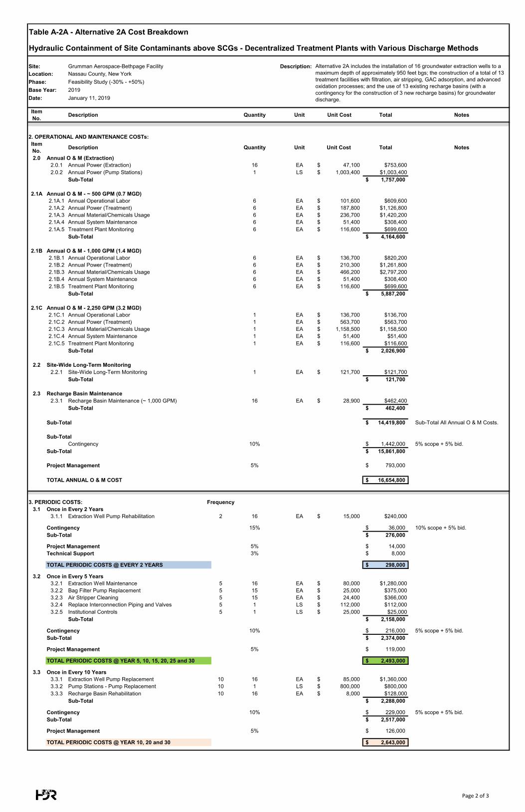
Table A-2A - Alternative 2A Cost Breakdown
Hydraulic Containment of Site Contaminants above SCGs - Decentralized Treatment Plants with Various Discharge Methods
Site: Grumman Aerospace-Bethpage Facility Description: Location: Nassau County, New YorkPhase: Feasibility Study (-30% - +50%)Base Year: 2019Date: January 11, 2019
Item No. Description Quantity Unit Unit Cost Total Notes
Alternative 2A includes the installation of 16 groundwater extraction wells to a maximum depth of approximately 950 feet bgs; the construction of a total of 13 treatment facilities with filtration, air stripping, GAC adsorption, and advanced oxidation processes; and the use of 13 existing recharge basins (with a contingency for the construction of 3 new recharge basins) for groundwater discharge.
2. OPERATIONAL AND MAINTENANCE COSTs:Item No. Description Quantity Unit Unit Cost Total Notes
2.0 Annual O & M (Extraction)2.0.1 Annual Power (Extraction) 16 EA 47,100$ $753,6002.0.2 Annual Power (Pump Stations) 1 LS 1,003,400$ $1,003,400
Sub-Total 1,757,000$
2.1A Annual O & M - ~ 500 GPM (0.7 MGD)2.1A.1 Annual Operational Labor 6 EA 101,600$ $609,6002.1A.2 Annual Power (Treatment) 6 EA 187,800$ $1,126,8002.1A.3 Annual Material/Chemicals Usage 6 EA 236,700$ $1,420,2002.1A.4 Annual System Maintenance 6 EA 51,400$ $308,4002.1A.5 Treatment Plant Monitoring 6 EA 116,600$ $699,600
Sub-Total 4,164,600$
2.1B Annual O & M - 1,000 GPM (1.4 MGD)2.1B.1 Annual Operational Labor 6 EA 136,700$ $820,2002.1B.2 Annual Power (Treatment) 6 EA 210,300$ $1,261,8002.1B.3 Annual Material/Chemicals Usage 6 EA 466,200$ $2,797,2002.1B.4 Annual System Maintenance 6 EA 51,400$ $308,4002.1B.5 Treatment Plant Monitoring 6 EA 116,600$ $699,600
Sub-Total 5,887,200$
2.1C Annual O & M - 2,250 GPM (3.2 MGD)2.1C.1 Annual Operational Labor 1 EA 136,700$ $136,7002.1C.2 Annual Power (Treatment) 1 EA 563,700$ $563,7002.1C.3 Annual Material/Chemicals Usage 1 EA 1,158,500$ $1,158,5002.1C.4 Annual System Maintenance 1 EA 51,400$ $51,4002.1C.5 Treatment Plant Monitoring 1 EA 116,600$ $116,600
Sub-Total 2,026,900$
2.2 Site-Wide Long-Term Monitoring2.2.1 Site-Wide Long-Term Monitoring 1 EA 121,700$ $121,700
Sub-Total 121,700$
2.3 Recharge Basin Maintenance 2.3.1 Recharge Basin Maintenance (~ 1,000 GPM) 16 EA 28,900$ $462,400
Sub-Total 462,400$
Sub-Total 14,419,800$ Sub-Total All Annual O & M Costs.
Sub-TotalContingency 10% 1,442,000$ 5% scope + 5% bid.
Sub-Total 15,861,800$
Project Management 5% 793,000$
TOTAL ANNUAL O & M COST 16,654,800$
3. PERIODIC COSTS: Frequency3.1 Once in Every 2 Years
3.1.1 Extraction Well Pump Rehabilitation 2 16 EA 15,000$ $240,000
Contingency 15% 36,000$ 10% scope + 5% bid.Sub-Total 276,000$
Project Management 5% 14,000$ Technical Support 3% 8,000$
TOTAL PERIODIC COSTS @ EVERY 2 YEARS 298,000$
3.2 Once in Every 5 Years3.2.1 Extraction Well Maintenance 5 16 EA 80,000$ $1,280,0003.2.2 Bag Filter Pump Replacement 5 15 EA 25,000$ $375,0003.2.3 Air Stripper Cleaning 5 15 EA 24,400$ $366,0003.2.4 Replace Interconnection Piping and Valves 5 1 LS 112,000$ $112,0003.2.5 Institutional Controls 5 1 LS 25,000$ $25,000
Sub-Total 2,158,000$
Contingency 10% 216,000$ 5% scope + 5% bid.Sub-Total 2,374,000$
Project Management 5% 119,000$
TOTAL PERIODIC COSTS @ YEAR 5, 10, 15, 20, 25 and 30 2,493,000$
3.3 Once in Every 10 Years3.3.1 Extraction Well Pump Replacement 10 16 EA 85,000$ $1,360,0003.3.2 Pump Stations - Pump Replacement 10 1 LS 800,000$ $800,0003.3.3 Recharge Basin Rehabilitation 10 16 EA 8,000$ $128,000
Sub-Total 2,288,000$
Contingency 10% 229,000$ 5% scope + 5% bid.Sub-Total 2,517,000$
Project Management 5% 126,000$
TOTAL PERIODIC COSTS @ YEAR 10, 20 and 30 2,643,000$
Page 2 of 3
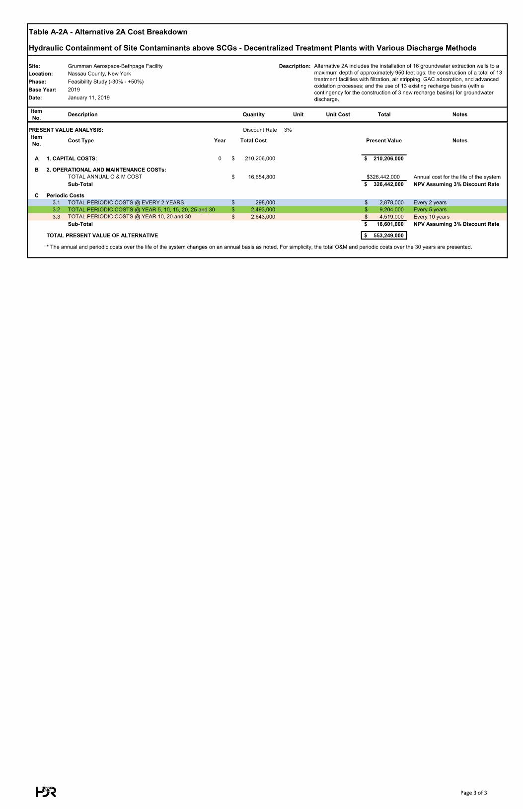
Table A-2A - Alternative 2A Cost Breakdown
Hydraulic Containment of Site Contaminants above SCGs - Decentralized Treatment Plants with Various Discharge Methods
Site: Grumman Aerospace-Bethpage Facility Description: Location: Nassau County, New YorkPhase: Feasibility Study (-30% - +50%)Base Year: 2019Date: January 11, 2019
Item No. Description Quantity Unit Unit Cost Total Notes
Alternative 2A includes the installation of 16 groundwater extraction wells to a maximum depth of approximately 950 feet bgs; the construction of a total of 13 treatment facilities with filtration, air stripping, GAC adsorption, and advanced oxidation processes; and the use of 13 existing recharge basins (with a contingency for the construction of 3 new recharge basins) for groundwater discharge.
PRESENT VALUE ANALYSIS: Discount Rate 3% Interest Rate: 0%Item No. Cost Type Year Total Cost Present Value Notes
A 1. CAPITAL COSTS: 0 210,206,000$ 210,206,000$
B 2. OPERATIONAL AND MAINTENANCE COSTs:TOTAL ANNUAL O & M COST 16,654,800$ $326,442,000 Annual cost for the life of the systemSub-Total 326,442,000$ NPV Assuming 3% Discount Rate
C Periodic Costs3.1 TOTAL PERIODIC COSTS @ EVERY 2 YEARS 298,000$ 2,878,000$ Every 2 years3.2 TOTAL PERIODIC COSTS @ YEAR 5, 10, 15, 20, 25 and 30 2,493,000$ 9,204,000$ Every 5 years3.3 TOTAL PERIODIC COSTS @ YEAR 10, 20 and 30 2,643,000$ 4,519,000$ Every 10 years
Sub-Total 16,601,000$ NPV Assuming 3% Discount Rate
TOTAL PRESENT VALUE OF ALTERNATIVE 553,249,000$
* The annual and periodic costs over the life of the system changes on an annual basis as noted. For simplicity, the total O&M and periodic costs over the 30 years are presented.
Page 3 of 3
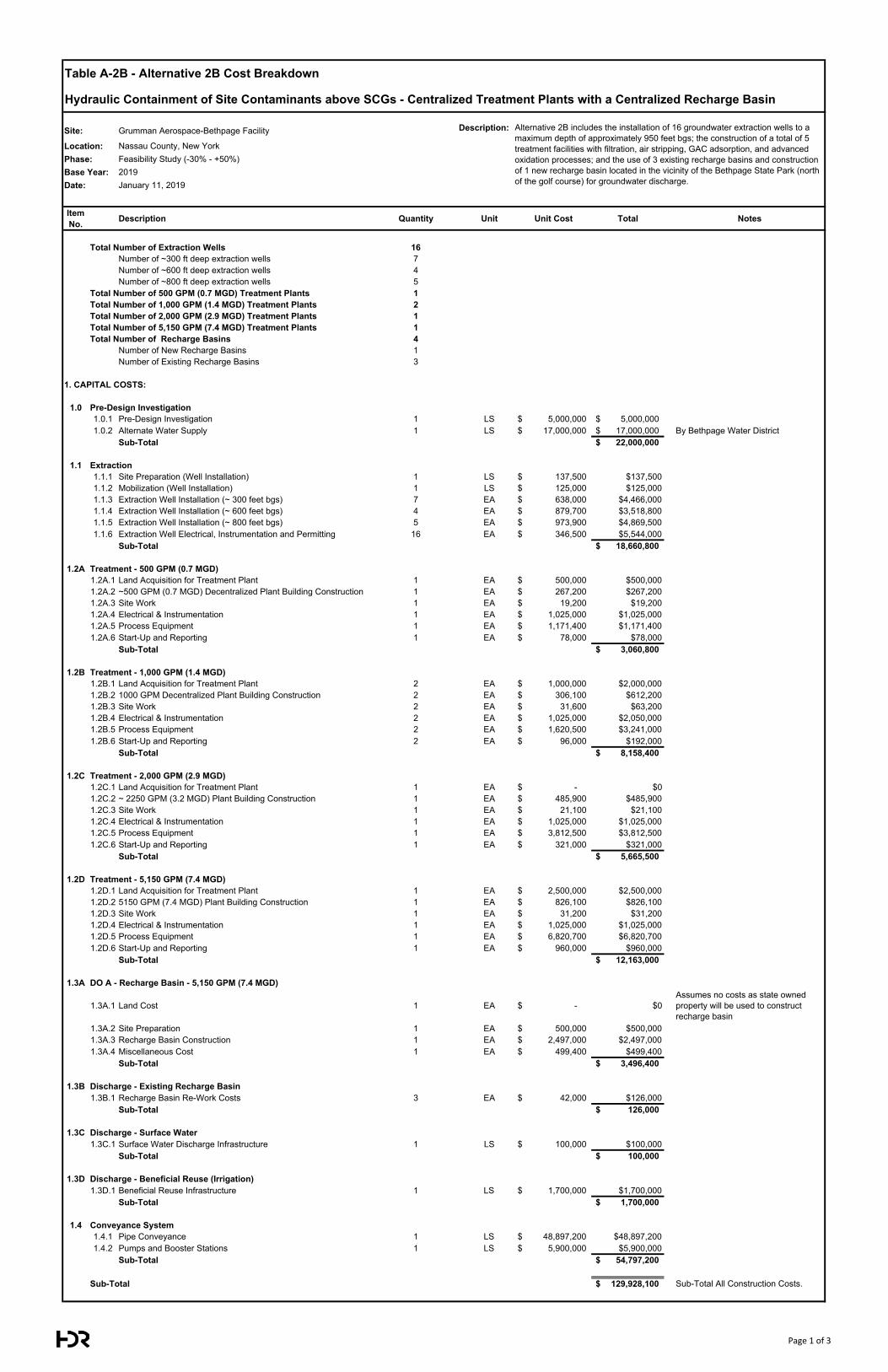
Table A-2B - Alternative 2B Cost Breakdown
Hydraulic Containment of Site Contaminants above SCGs - Centralized Treatment Plants with a Centralized Recharge Basin
Site: Grumman Aerospace-Bethpage Facility Description:
Location: Nassau County, New YorkPhase: Feasibility Study (-30% - +50%)Base Year: 2019Date: January 11, 2019
Item No. Description Quantity Unit Unit Cost Total Notes
Total Number of Extraction Wells 16Number of ~300 ft deep extraction wells 7Number of ~600 ft deep extraction wells 4Number of ~800 ft deep extraction wells 5
Total Number of 500 GPM (0.7 MGD) Treatment Plants 1Total Number of 1,000 GPM (1.4 MGD) Treatment Plants 2Total Number of 2,000 GPM (2.9 MGD) Treatment Plants 1Total Number of 5,150 GPM (7.4 MGD) Treatment Plants 1Total Number of Recharge Basins 4
Number of New Recharge Basins 1Number of Existing Recharge Basins 3
1. CAPITAL COSTS:
1.0 Pre-Design Investigation1.0.1 Pre-Design Investigation 1 LS 5,000,000$ 5,000,000$ 1.0.2 Alternate Water Supply 1 LS 17,000,000$ 17,000,000$ By Bethpage Water District
Sub-Total 22,000,000$
1.1 Extraction1.1.1 Site Preparation (Well Installation) 1 LS 137,500$ $137,5001.1.2 Mobilization (Well Installation) 1 LS 125,000$ $125,0001.1.3 Extraction Well Installation (~ 300 feet bgs) 7 EA 638,000$ $4,466,0001.1.4 Extraction Well Installation (~ 600 feet bgs) 4 EA 879,700$ $3,518,8001.1.5 Extraction Well Installation (~ 800 feet bgs) 5 EA 973,900$ $4,869,5001.1.6 Extraction Well Electrical, Instrumentation and Permitting 16 EA 346,500$ $5,544,000
Sub-Total 18,660,800$
1.2A Treatment - 500 GPM (0.7 MGD)1.2A.1 Land Acquisition for Treatment Plant 1 EA 500,000$ $500,0001.2A.2 ~500 GPM (0.7 MGD) Decentralized Plant Building Construction 1 EA 267,200$ $267,2001.2A.3 Site Work 1 EA 19,200$ $19,2001.2A.4 Electrical & Instrumentation 1 EA 1,025,000$ $1,025,0001.2A.5 Process Equipment 1 EA 1,171,400$ $1,171,4001.2A.6 Start-Up and Reporting 1 EA 78,000$ $78,000
Sub-Total 3,060,800$
1.2B Treatment - 1,000 GPM (1.4 MGD)1.2B.1 Land Acquisition for Treatment Plant 2 EA 1,000,000$ $2,000,0001.2B.2 1000 GPM Decentralized Plant Building Construction 2 EA 306,100$ $612,2001.2B.3 Site Work 2 EA 31,600$ $63,2001.2B.4 Electrical & Instrumentation 2 EA 1,025,000$ $2,050,0001.2B.5 Process Equipment 2 EA 1,620,500$ $3,241,0001.2B.6 Start-Up and Reporting 2 EA 96,000$ $192,000
Sub-Total 8,158,400$
1.2C Treatment - 2,000 GPM (2.9 MGD)1.2C.1 Land Acquisition for Treatment Plant 1 EA -$ $01.2C.2 ~ 2250 GPM (3.2 MGD) Plant Building Construction 1 EA 485,900$ $485,9001.2C.3 Site Work 1 EA 21,100$ $21,1001.2C.4 Electrical & Instrumentation 1 EA 1,025,000$ $1,025,0001.2C.5 Process Equipment 1 EA 3,812,500$ $3,812,5001.2C.6 Start-Up and Reporting 1 EA 321,000$ $321,000
Sub-Total 5,665,500$
1.2D Treatment - 5,150 GPM (7.4 MGD)1.2D.1 Land Acquisition for Treatment Plant 1 EA 2,500,000$ $2,500,0001.2D.2 5150 GPM (7.4 MGD) Plant Building Construction 1 EA 826,100$ $826,1001.2D.3 Site Work 1 EA 31,200$ $31,2001.2D.4 Electrical & Instrumentation 1 EA 1,025,000$ $1,025,0001.2D.5 Process Equipment 1 EA 6,820,700$ $6,820,7001.2D.6 Start-Up and Reporting 1 EA 960,000$ $960,000
Sub-Total 12,163,000$
1.3A DO A - Recharge Basin - 5,150 GPM (7.4 MGD)
1.3A.1 Land Cost 1 EA -$ $0Assumes no costs as state owned property will be used to construct recharge basin
1.3A.2 Site Preparation 1 EA 500,000$ $500,0001.3A.3 Recharge Basin Construction 1 EA 2,497,000$ $2,497,0001.3A.4 Miscellaneous Cost 1 EA 499,400$ $499,400
Sub-Total 3,496,400$
1.3B Discharge - Existing Recharge Basin1.3B.1 Recharge Basin Re-Work Costs 3 EA 42,000$ $126,000
Sub-Total 126,000$
1.3C Discharge - Surface Water1.3C.1 Surface Water Discharge Infrastructure 1 LS 100,000$ $100,000
Sub-Total 100,000$
1.3D Discharge - Beneficial Reuse (Irrigation)1.3D.1 Beneficial Reuse Infrastructure 1 LS 1,700,000$ $1,700,000
Sub-Total 1,700,000$
1.4 Conveyance System1.4.1 Pipe Conveyance 1 LS 48,897,200$ $48,897,2001.4.2 Pumps and Booster Stations 1 LS 5,900,000$ $5,900,000
Sub-Total 54,797,200$
Sub-Total 129,928,100$ Sub-Total All Construction Costs.
Alternative 2B includes the installation of 16 groundwater extraction wells to a maximum depth of approximately 950 feet bgs; the construction of a total of 5 treatment facilities with filtration, air stripping, GAC adsorption, and advanced oxidation processes; and the use of 3 existing recharge basins and construction of 1 new recharge basin located in the vicinity of the Bethpage State Park (north of the golf course) for groundwater discharge.
Page 1 of 3
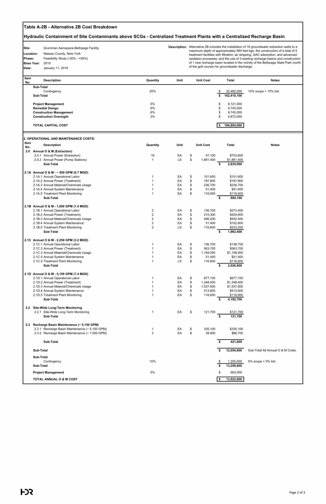
Table A-2B - Alternative 2B Cost Breakdown
Hydraulic Containment of Site Contaminants above SCGs - Centralized Treatment Plants with a Centralized Recharge Basin
Site: Grumman Aerospace-Bethpage Facility Description:
Location: Nassau County, New YorkPhase: Feasibility Study (-30% - +50%)Base Year: 2019Date: January 11, 2019
Item No. Description Quantity Unit Unit Cost Total Notes
Alternative 2B includes the installation of 16 groundwater extraction wells to a maximum depth of approximately 950 feet bgs; the construction of a total of 5 treatment facilities with filtration, air stripping, GAC adsorption, and advanced oxidation processes; and the use of 3 existing recharge basins and construction of 1 new recharge basin located in the vicinity of the Bethpage State Park (north of the golf course) for groundwater discharge.
Sub-TotalContingency 25% 32,482,000$ 10% scope + 15% bid.
Sub-Total 162,410,100$
Project Management 5% 8,121,000$ Remedial Design 6% 9,745,000$ Construction Management 6% 9,745,000$ Construction Oversight 3% 4,872,000$
TOTAL CAPITAL COST 194,894,000$
2. OPERATIONAL AND MAINTENANCE COSTS:Item No. Description Quantity Unit Unit Cost Total Notes
2.0 Annual O & M (Extraction)2.0.1 Annual Power (Extraction) 16 EA 47,100$ $753,6002.0.2 Annual Power (Pump Stations) 1 LS 1,881,400$ $1,881,400
Sub-Total 2,635,000$
2.1A Annual O & M - ~ 500 GPM (0.7 MGD)2.1A.1 Annual Operational Labor 1 EA 101,600$ $101,6002.1A.2 Annual Power (Treatment) 1 EA 187,800$ $187,8002.1A.3 Annual Material/Chemicals Usage 1 EA 236,700$ $236,7002.1A.4 Annual System Maintenance 1 EA 51,400$ $51,4002.1A.5 Treatment Plant Monitoring 1 EA 116,600$ $116,600
Sub-Total 694,100$
2.1B Annual O & M - 1,000 GPM (1.4 MGD)2.1B.1 Annual Operational Labor 2 EA 136,700$ $273,4002.1B.2 Annual Power (Treatment) 2 EA 210,300$ $420,6002.1B.3 Annual Material/Chemicals Usage 2 EA 466,200$ $932,4002.1B.4 Annual System Maintenance 2 EA 51,400$ $102,8002.1B.5 Treatment Plant Monitoring 2 LS 116,600$ $233,200
Sub-Total 1,962,400$
2.1C Annual O & M - 2,250 GPM (3.2 MGD)2.1C.1 Annual Operational Labor 1 EA 136,700$ $136,7002.1C.2 Annual Power (Treatment) 1 EA 563,700$ $563,7002.1C.3 Annual Material/Chemicals Usage 1 EA 1,158,500$ $1,158,5002.1C.4 Annual System Maintenance 1 EA 51,400$ $51,4002.1C.5 Treatment Plant Monitoring 1 LS 116,600$ $116,600
Sub-Total 2,026,900$
2.1D Annual O & M - 5,150 GPM (7.4 MGD)2.1D.1 Annual Operational Labor 1 EA 677,100$ $677,1002.1D.2 Annual Power (Treatment) 1 EA 1,348,400$ $1,348,4002.1D.3 Annual Material/Chemicals Usage 1 EA 1,537,000$ $1,537,0002.1D.4 Annual System Maintenance 1 EA 513,600$ $513,6002.1D.5 Treatment Plant Monitoring 1 EA 116,600$ $116,600
Sub-Total 4,192,700$
2.2 Site-Wide Long-Term Monitoring2.2.1 Site-Wide Long-Term Monitoring 1 EA 121,700$ $121,700
Sub-Total 121,700$
2.3 Recharge Basin Maintenance (~ 5,150 GPM)2.3.1 Recharge Basin Maintenance (~ 5,150 GPM) 1 EA 335,100$ $335,1002.3.2 Recharge Basin Maintenance (~ 1,000 GPM) 3 EA 28,900$ $86,700
Sub-Total 421,800$
Sub-Total 12,054,600$ Sub-Total All Annual O & M Costs.
Sub-TotalContingency 10% 1,205,000$ 5% scope + 5% bid.
Sub-Total 13,259,600$
Project Management 5% 663,000$
TOTAL ANNUAL O & M COST 13,922,600$
Page 2 of 3
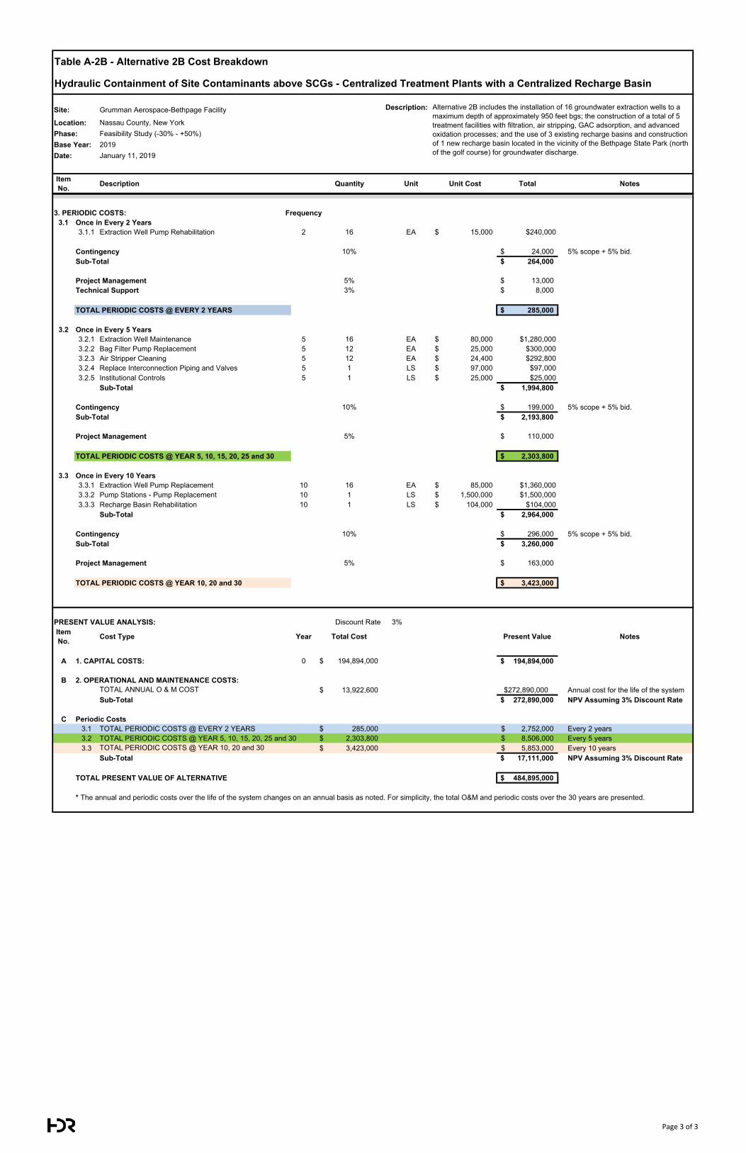
Table A-2B - Alternative 2B Cost Breakdown
Hydraulic Containment of Site Contaminants above SCGs - Centralized Treatment Plants with a Centralized Recharge Basin
Site: Grumman Aerospace-Bethpage Facility Description:
Location: Nassau County, New YorkPhase: Feasibility Study (-30% - +50%)Base Year: 2019Date: January 11, 2019
Item No. Description Quantity Unit Unit Cost Total Notes
Alternative 2B includes the installation of 16 groundwater extraction wells to a maximum depth of approximately 950 feet bgs; the construction of a total of 5 treatment facilities with filtration, air stripping, GAC adsorption, and advanced oxidation processes; and the use of 3 existing recharge basins and construction of 1 new recharge basin located in the vicinity of the Bethpage State Park (north of the golf course) for groundwater discharge.
3. PERIODIC COSTS: Frequency3.1 Once in Every 2 Years
3.1.1 Extraction Well Pump Rehabilitation 2 16 EA 15,000$ $240,000
Contingency 10% 24,000$ 5% scope + 5% bid.Sub-Total 264,000$
Project Management 5% 13,000$ Technical Support 3% 8,000$
TOTAL PERIODIC COSTS @ EVERY 2 YEARS 285,000$
3.2 Once in Every 5 Years3.2.1 Extraction Well Maintenance 5 16 EA 80,000$ $1,280,0003.2.2 Bag Filter Pump Replacement 5 12 EA 25,000$ $300,0003.2.3 Air Stripper Cleaning 5 12 EA 24,400$ $292,8003.2.4 Replace Interconnection Piping and Valves 5 1 LS 97,000$ $97,0003.2.5 Institutional Controls 5 1 LS 25,000$ $25,000
Sub-Total 1,994,800$
Contingency 10% 199,000$ 5% scope + 5% bid.Sub-Total 2,193,800$
Project Management 5% 110,000$
TOTAL PERIODIC COSTS @ YEAR 5, 10, 15, 20, 25 and 30 2,303,800$
3.3 Once in Every 10 Years3.3.1 Extraction Well Pump Replacement 10 16 EA 85,000$ $1,360,0003.3.2 Pump Stations - Pump Replacement 10 1 LS 1,500,000$ $1,500,0003.3.3 Recharge Basin Rehabilitation 10 1 LS 104,000$ $104,000
Sub-Total 2,964,000$
Contingency 10% 296,000$ 5% scope + 5% bid.Sub-Total 3,260,000$
Project Management 5% 163,000$
TOTAL PERIODIC COSTS @ YEAR 10, 20 and 30 3,423,000$
PRESENT VALUE ANALYSIS: Discount Rate 3% Interest Rate: 0%Item No. Cost Type Year Total Cost Present Value Notes
A 1. CAPITAL COSTS: 0 194,894,000$ 194,894,000$
B 2. OPERATIONAL AND MAINTENANCE COSTS:TOTAL ANNUAL O & M COST 13,922,600$ $272,890,000 Annual cost for the life of the systemSub-Total 272,890,000$ NPV Assuming 3% Discount Rate
C Periodic Costs3.1 TOTAL PERIODIC COSTS @ EVERY 2 YEARS 285,000$ 2,752,000$ Every 2 years3.2 TOTAL PERIODIC COSTS @ YEAR 5, 10, 15, 20, 25 and 30 2,303,800$ 8,506,000$ Every 5 years3.3 TOTAL PERIODIC COSTS @ YEAR 10, 20 and 30 3,423,000$ 5,853,000$ Every 10 years
Sub-Total 17,111,000$ NPV Assuming 3% Discount Rate
TOTAL PRESENT VALUE OF ALTERNATIVE 484,895,000$
* The annual and periodic costs over the life of the system changes on an annual basis as noted. For simplicity, the total O&M and periodic costs over the 30 years are presented.
Page 3 of 3
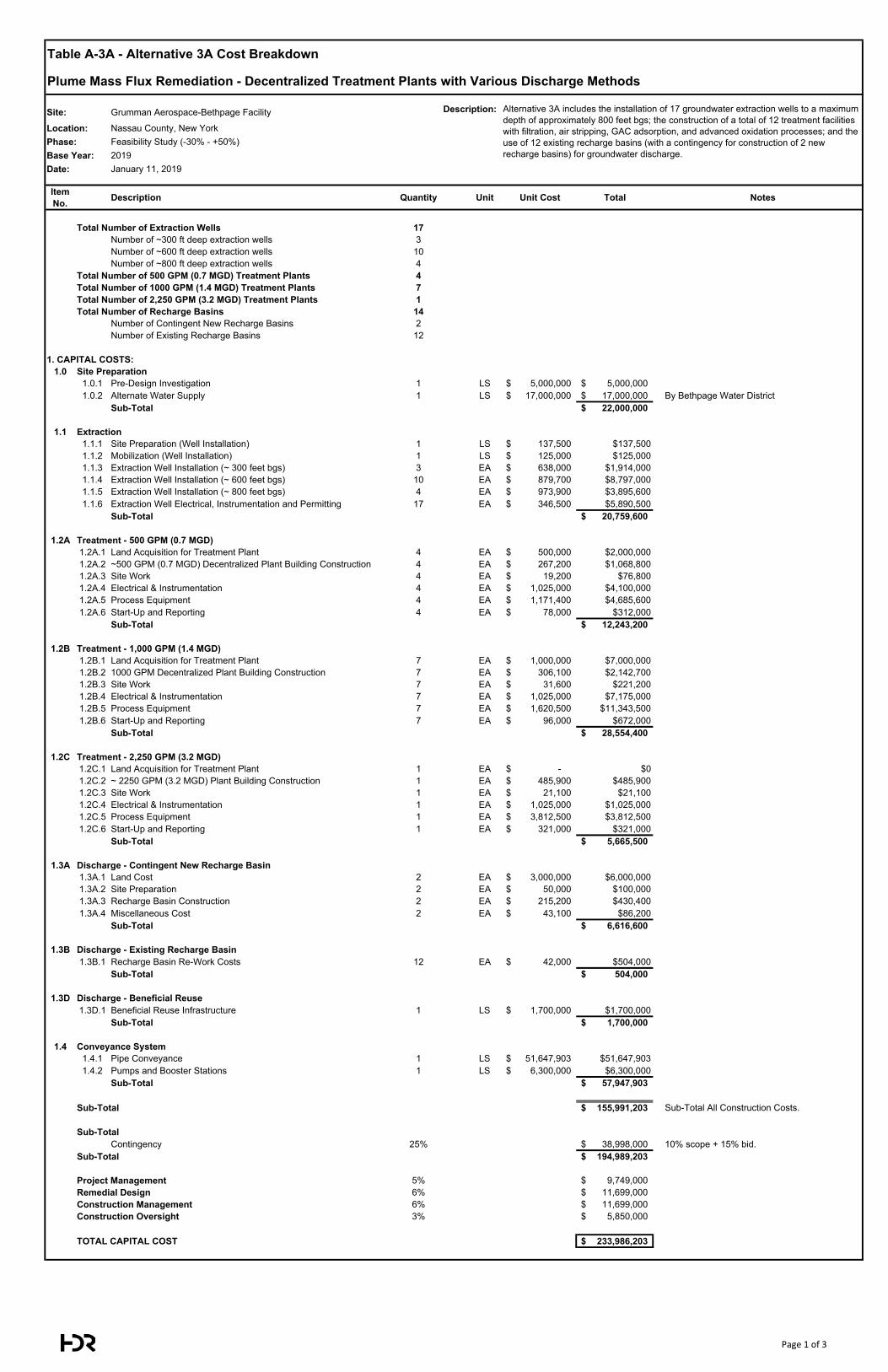
Table A-3A - Alternative 3A Cost Breakdown
Plume Mass Flux Remediation - Decentralized Treatment Plants with Various Discharge Methods
Site: Grumman Aerospace-Bethpage Facility Description:
Location: Nassau County, New YorkPhase: Feasibility Study (-30% - +50%)Base Year: 2019Date: January 11, 2019
Item No. Description Quantity Unit Unit Cost Total Notes
Total Number of Extraction Wells 17Number of ~300 ft deep extraction wells 3Number of ~600 ft deep extraction wells 10Number of ~800 ft deep extraction wells 4
Total Number of 500 GPM (0.7 MGD) Treatment Plants 4Total Number of 1000 GPM (1.4 MGD) Treatment Plants 7Total Number of 2,250 GPM (3.2 MGD) Treatment Plants 1Total Number of Recharge Basins 14
Number of Contingent New Recharge Basins 2Number of Existing Recharge Basins 12
1. CAPITAL COSTS:1.0 Site Preparation
1.0.1 Pre-Design Investigation 1 LS 5,000,000$ 5,000,000$ 1.0.2 Alternate Water Supply 1 LS 17,000,000$ 17,000,000$ By Bethpage Water District
Sub-Total 22,000,000$
1.1 Extraction1.1.1 Site Preparation (Well Installation) 1 LS 137,500$ $137,5001.1.2 Mobilization (Well Installation) 1 LS 125,000$ $125,0001.1.3 Extraction Well Installation (~ 300 feet bgs) 3 EA 638,000$ $1,914,0001.1.4 Extraction Well Installation (~ 600 feet bgs) 10 EA 879,700$ $8,797,0001.1.5 Extraction Well Installation (~ 800 feet bgs) 4 EA 973,900$ $3,895,6001.1.6 Extraction Well Electrical, Instrumentation and Permitting 17 EA 346,500$ $5,890,500
Sub-Total 20,759,600$
1.2A Treatment - 500 GPM (0.7 MGD)1.2A.1 Land Acquisition for Treatment Plant 4 EA 500,000$ $2,000,0001.2A.2 ~500 GPM (0.7 MGD) Decentralized Plant Building Construction 4 EA 267,200$ $1,068,8001.2A.3 Site Work 4 EA 19,200$ $76,8001.2A.4 Electrical & Instrumentation 4 EA 1,025,000$ $4,100,0001.2A.5 Process Equipment 4 EA 1,171,400$ $4,685,6001.2A.6 Start-Up and Reporting 4 EA 78,000$ $312,000
Sub-Total 12,243,200$
1.2B Treatment - 1,000 GPM (1.4 MGD)1.2B.1 Land Acquisition for Treatment Plant 7 EA 1,000,000$ $7,000,0001.2B.2 1000 GPM Decentralized Plant Building Construction 7 EA 306,100$ $2,142,7001.2B.3 Site Work 7 EA 31,600$ $221,2001.2B.4 Electrical & Instrumentation 7 EA 1,025,000$ $7,175,0001.2B.5 Process Equipment 7 EA 1,620,500$ $11,343,5001.2B.6 Start-Up and Reporting 7 EA 96,000$ $672,000
Sub-Total 28,554,400$
1.2C Treatment - 2,250 GPM (3.2 MGD)1.2C.1 Land Acquisition for Treatment Plant 1 EA -$ $01.2C.2 ~ 2250 GPM (3.2 MGD) Plant Building Construction 1 EA 485,900$ $485,9001.2C.3 Site Work 1 EA 21,100$ $21,1001.2C.4 Electrical & Instrumentation 1 EA 1,025,000$ $1,025,0001.2C.5 Process Equipment 1 EA 3,812,500$ $3,812,5001.2C.6 Start-Up and Reporting 1 EA 321,000$ $321,000
Sub-Total 5,665,500$
1.3A Discharge - Contingent New Recharge Basin1.3A.1 Land Cost 2 EA 3,000,000$ $6,000,0001.3A.2 Site Preparation 2 EA 50,000$ $100,0001.3A.3 Recharge Basin Construction 2 EA 215,200$ $430,4001.3A.4 Miscellaneous Cost 2 EA 43,100$ $86,200
Sub-Total 6,616,600$
1.3B Discharge - Existing Recharge Basin1.3B.1 Recharge Basin Re-Work Costs 12 EA 42,000$ $504,000
Sub-Total 504,000$
1.3D Discharge - Beneficial Reuse1.3D.1 Beneficial Reuse Infrastructure 1 LS 1,700,000$ $1,700,000
Sub-Total 1,700,000$
1.4 Conveyance System1.4.1 Pipe Conveyance 1 LS 51,647,903$ $51,647,9031.4.2 Pumps and Booster Stations 1 LS 6,300,000$ $6,300,000
Sub-Total 57,947,903$
Sub-Total 155,991,203$ Sub-Total All Construction Costs.
Sub-TotalContingency 25% 38,998,000$ 10% scope + 15% bid.
Sub-Total 194,989,203$
Project Management 5% 9,749,000$ Remedial Design 6% 11,699,000$ Construction Management 6% 11,699,000$ Construction Oversight 3% 5,850,000$
TOTAL CAPITAL COST 233,986,203$
Alternative 3A includes the installation of 17 groundwater extraction wells to a maximum depth of approximately 800 feet bgs; the construction of a total of 12 treatment facilities with filtration, air stripping, GAC adsorption, and advanced oxidation processes; and the use of 12 existing recharge basins (with a contingency for construction of 2 new recharge basins) for groundwater discharge.
Page 1 of 3
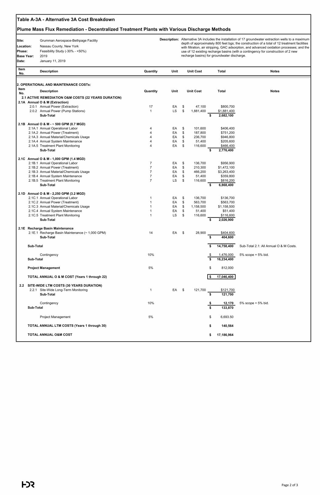
Table A-3A - Alternative 3A Cost Breakdown
Plume Mass Flux Remediation - Decentralized Treatment Plants with Various Discharge Methods
Site: Grumman Aerospace-Bethpage Facility Description:
Location: Nassau County, New YorkPhase: Feasibility Study (-30% - +50%)Base Year: 2019Date: January 11, 2019
Item No. Description Quantity Unit Unit Cost Total Notes
Alternative 3A includes the installation of 17 groundwater extraction wells to a maximum depth of approximately 800 feet bgs; the construction of a total of 12 treatment facilities with filtration, air stripping, GAC adsorption, and advanced oxidation processes; and the use of 12 existing recharge basins (with a contingency for construction of 2 new recharge basins) for groundwater discharge.
2. OPERATIONAL AND MAINTENANCE COSTs:Item No. Description Quantity Unit Unit Cost Total Notes
2.1A Annual O & M (Extraction)2.0.1 Annual Power (Extraction) 17 EA 47,100$ $800,7002.0.2 Annual Power (Pump Stations) 1 LS 1,881,400$ $1,881,400
Sub-Total 2,682,100$
2.1B Annual O & M - ~ 500 GPM (0.7 MGD)2.1A.1 Annual Operational Labor 4 EA 101,600$ $406,4002.1A.2 Annual Power (Treatment) 4 EA 187,800$ $751,2002.1A.3 Annual Material/Chemicals Usage 4 EA 236,700$ $946,8002.1A.4 Annual System Maintenance 4 EA 51,400$ $205,6002.1A.5 Treatment Plant Monitoring 4 EA 116,600$ $466,400
Sub-Total 2,776,400$
2.1C Annual O & M - 1,000 GPM (1.4 MGD)2.1B.1 Annual Operational Labor 7 EA 136,700$ $956,9002.1B.2 Annual Power (Treatment) 7 EA 210,300$ $1,472,1002.1B.3 Annual Material/Chemicals Usage 7 EA 466,200$ $3,263,4002.1B.4 Annual System Maintenance 7 EA 51,400$ $359,8002.1B.5 Treatment Plant Monitoring 7 LS 116,600$ $816,200
Sub-Total 6,868,400$
2.1D Annual O & M - 2,250 GPM (3.2 MGD)2.1C.1 Annual Operational Labor 1 EA 136,700$ $136,7002.1C.2 Annual Power (Treatment) 1 EA 563,700$ $563,7002.1C.3 Annual Material/Chemicals Usage 1 EA 1,158,500$ $1,158,5002.1C.4 Annual System Maintenance 1 EA 51,400$ $51,4002.1C.5 Treatment Plant Monitoring 1 LS 116,600$ $116,600
Sub-Total 2,026,900$
2.1E Recharge Basin Maintenance2.1E.1 Recharge Basin Maintenance (~ 1,000 GPM) 14 EA 28,900$ $404,600
Sub-Total 404,600$
Sub-Total 14,758,400$ Sub-Total 2.1: All Annual O & M Costs.
Contingency 10% 1,476,000$ 5% scope + 5% bid.Sub-Total 16,234,400$
Project Management 5% 812,000$
TOTAL ANNUAL O & M COST (Years 1 through 22) 17,046,400$
2.2 SITE-WIDE LTM COSTS (30 YEARS DURATION)2.2.1 Site-Wide Long-Term Monitoring 1 EA 121,700$ $121,700
Sub-Total 121,700$
Contingency 10% 12,170$ 5% scope + 5% bid.133,870$
Project Management 5% 6,693.50$
140,564$
17,186,964$ TOTAL ANNUAL O&M COST
2.1 ACTIVE REMEDIATION O&M COSTS (22 YEARS DURATION)
Sub-Total
TOTAL ANNUAL LTM COSTS (Years 1 through 30)
Page 2 of 3
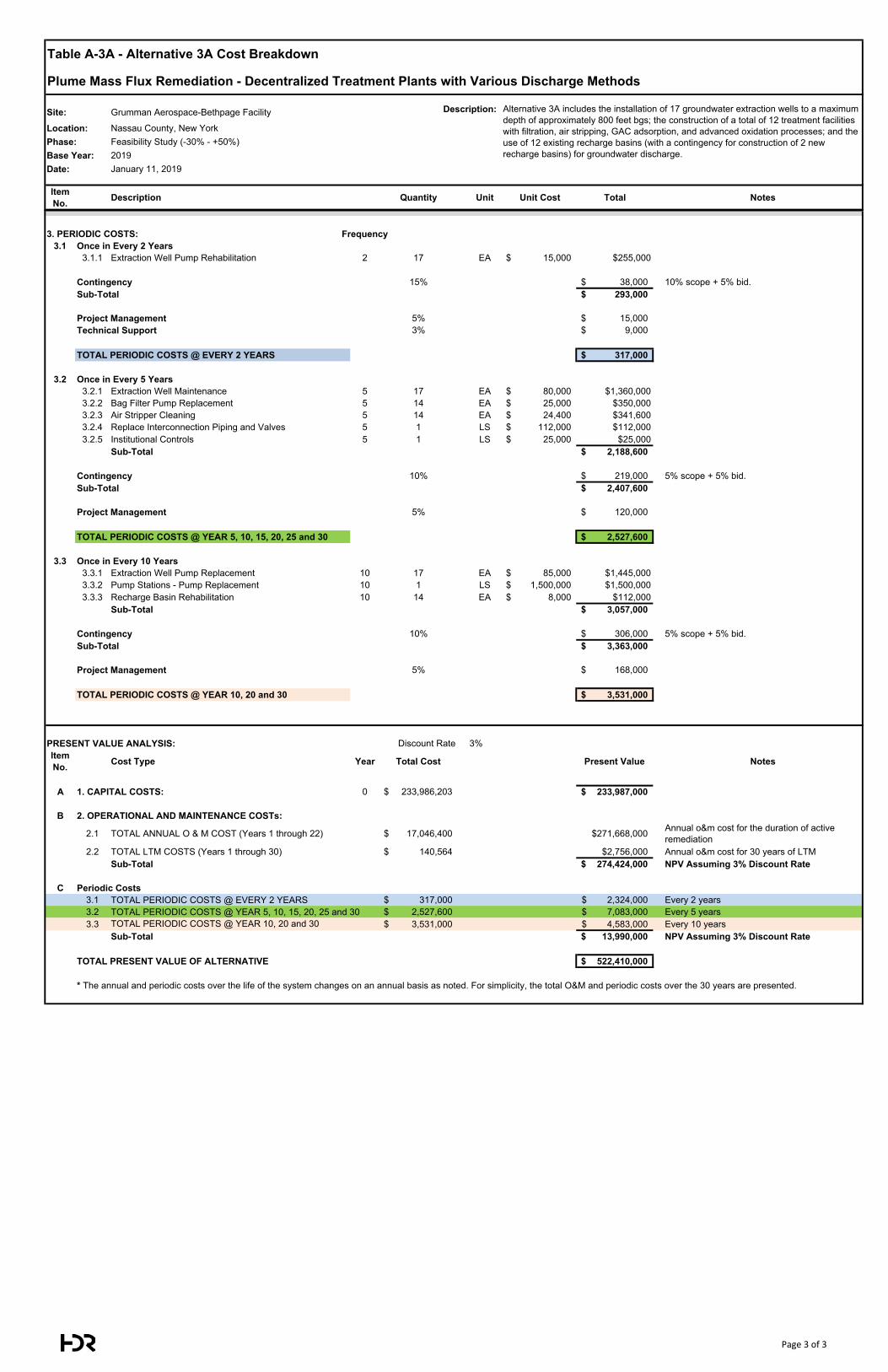
Table A-3A - Alternative 3A Cost Breakdown
Plume Mass Flux Remediation - Decentralized Treatment Plants with Various Discharge Methods
Site: Grumman Aerospace-Bethpage Facility Description:
Location: Nassau County, New YorkPhase: Feasibility Study (-30% - +50%)Base Year: 2019Date: January 11, 2019
Item No. Description Quantity Unit Unit Cost Total Notes
Alternative 3A includes the installation of 17 groundwater extraction wells to a maximum depth of approximately 800 feet bgs; the construction of a total of 12 treatment facilities with filtration, air stripping, GAC adsorption, and advanced oxidation processes; and the use of 12 existing recharge basins (with a contingency for construction of 2 new recharge basins) for groundwater discharge.
3. PERIODIC COSTS: Frequency3.1 Once in Every 2 Years
3.1.1 Extraction Well Pump Rehabilitation 2 17 EA 15,000$ $255,000
Contingency 15% 38,000$ 10% scope + 5% bid.Sub-Total 293,000$
Project Management 5% 15,000$ Technical Support 3% 9,000$
TOTAL PERIODIC COSTS @ EVERY 2 YEARS 317,000$
3.2 Once in Every 5 Years3.2.1 Extraction Well Maintenance 5 17 EA 80,000$ $1,360,0003.2.2 Bag Filter Pump Replacement 5 14 EA 25,000$ $350,0003.2.3 Air Stripper Cleaning 5 14 EA 24,400$ $341,6003.2.4 Replace Interconnection Piping and Valves 5 1 LS 112,000$ $112,0003.2.5 Institutional Controls 5 1 LS 25,000$ $25,000
Sub-Total 2,188,600$
Contingency 10% 219,000$ 5% scope + 5% bid.Sub-Total 2,407,600$
Project Management 5% 120,000$
TOTAL PERIODIC COSTS @ YEAR 5, 10, 15, 20, 25 and 30 2,527,600$
3.3 Once in Every 10 Years3.3.1 Extraction Well Pump Replacement 10 17 EA 85,000$ $1,445,0003.3.2 Pump Stations - Pump Replacement 10 1 LS 1,500,000$ $1,500,0003.3.3 Recharge Basin Rehabilitation 10 14 EA 8,000$ $112,000
Sub-Total 3,057,000$
Contingency 10% 306,000$ 5% scope + 5% bid.Sub-Total 3,363,000$
Project Management 5% 168,000$
TOTAL PERIODIC COSTS @ YEAR 10, 20 and 30 3,531,000$
PRESENT VALUE ANALYSIS: Discount Rate 3% Interest Rate: 0%Item No. Cost Type Year Total Cost Present Value Notes
A 1. CAPITAL COSTS: 0 233,986,203$ 233,987,000$
B 2. OPERATIONAL AND MAINTENANCE COSTs:
2.1 TOTAL ANNUAL O & M COST (Years 1 through 22) 17,046,400$ $271,668,000 Annual o&m cost for the duration of active remediation
2.2 TOTAL LTM COSTS (Years 1 through 30) 140,564$ $2,756,000 Annual o&m cost for 30 years of LTMSub-Total 274,424,000$ NPV Assuming 3% Discount Rate
C Periodic Costs3.1 TOTAL PERIODIC COSTS @ EVERY 2 YEARS 317,000$ 2,324,000$ Every 2 years3.2 TOTAL PERIODIC COSTS @ YEAR 5, 10, 15, 20, 25 and 30 2,527,600$ 7,083,000$ Every 5 years3.3 TOTAL PERIODIC COSTS @ YEAR 10, 20 and 30 3,531,000$ 4,583,000$ Every 10 years
Sub-Total 13,990,000$ NPV Assuming 3% Discount Rate
TOTAL PRESENT VALUE OF ALTERNATIVE 522,410,000$
* The annual and periodic costs over the life of the system changes on an annual basis as noted. For simplicity, the total O&M and periodic costs over the 30 years are presented.
Page 3 of 3
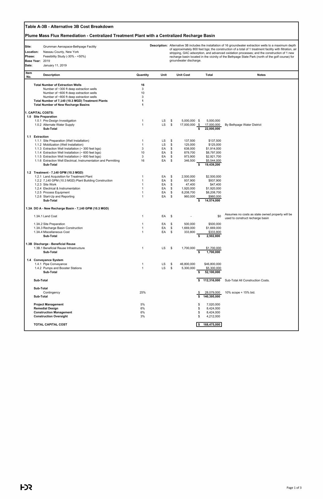
Table A-3B - Alternative 3B Cost Breakdown
Plume Mass Flux Remediation - Centralized Treatment Plant with a Centralized Recharge Basin
Site: Grumman Aerospace-Bethpage Facility Description:
Location: Nassau County, New YorkPhase: Feasibility Study (-30% - +50%)Base Year: 2019Date: January 11, 2019
Item No. Description Quantity Unit Unit Cost Total Notes
Total Number of Extraction Wells 16Number of ~300 ft deep extraction wells 3Number of ~600 ft deep extraction wells 10Number of ~800 ft deep extraction wells 3
Total Number of 7,140 (10.3 MGD) Treatment Plants 1Total Number of New Recharge Basins 1
1. CAPITAL COSTS:1.0 Site Preparation
1.0.1 Pre-Design Investigation 1 LS 5,000,000$ 5,000,000$ 1.0.2 Alternate Water Supply 1 LS 17,000,000$ 17,000,000$ By Bethpage Water District
Sub-Total 22,000,000$
1.1 Extraction1.1.1 Site Preparation (Well Installation) 1 LS 137,500$ $137,5001.1.2 Mobilization (Well Installation) 1 LS 125,000$ $125,0001.1.3 Extraction Well Installation (~ 300 feet bgs) 3 EA 638,000$ $1,914,0001.1.4 Extraction Well Installation (~ 600 feet bgs) 10 EA 879,700$ $8,797,0001.1.5 Extraction Well Installation (~ 800 feet bgs) 3 EA 973,900$ $2,921,7001.1.6 Extraction Well Electrical, Instrumentation and Permitting 16 EA 346,500$ $5,544,000
Sub-Total 19,439,200$
1.2 Treatment - 7,140 GPM (10.3 MGD)1.2.1 Land Acquisition for Treatment Plant 1 EA 2,500,000$ $2,500,0001.2.2 7,140 GPM (10.3 MGD) Plant Building Construction 1 EA 937,900$ $937,9001.2.3 Site Work 1 EA 47,400$ $47,4001.2.4 Electrical & Instrumentation 1 EA 1,920,000$ $1,920,0001.2.5 Process Equipment 1 EA 8,208,700$ $8,208,7001.2.6 Start-Up and Reporting 1 EA 960,000$ $960,000
Sub-Total 14,574,000$
1.3A DO A - New Recharge Basin - 7,140 GPM (10.3 MGD)
1.3A.1 Land Cost 1 EA -$ $0 Assumes no costs as state owned property will be used to construct recharge basin
1.3A.2 Site Preparation 1 EA 500,000$ $500,0001.3A.3 Recharge Basin Construction 1 EA 1,669,000$ $1,669,0001.3A.4 Miscellaneous Cost 1 EA 333,800$ $333,800
Sub-Total 2,502,800$
1.3B Discharge - Beneficial Reuse1.3B.1 Beneficial Reuse Infrastructure 1 LS 1,700,000$ $1,700,000
Sub-Total 1,700,000$
1.4 Conveyance System1.4.1 Pipe Conveyance 1 LS 46,800,000$ $46,800,0001.4.2 Pumps and Booster Stations 1 LS 5,300,000$ $5,300,000
Sub-Total 52,100,000$
Sub-Total 112,316,000$ Sub-Total All Construction Costs.
Sub-TotalContingency 25% 28,079,000$ 10% scope + 15% bid.
Sub-Total 140,395,000$
Project Management 5% 7,020,000$ Remedial Design 6% 8,424,000$ Construction Management 6% 8,424,000$ Construction Oversight 3% 4,212,000$
TOTAL CAPITAL COST 168,475,000$
Alternative 3B includes the installation of 16 groundwater extraction wells to a maximum depth of approximately 800 feet bgs; the construction of a total of 1 treatment facility with filtration, air stripping, GAC adsorption, and advanced oxidation processes; and the construction of 1 new recharge basin located in the vicinity of the Bethpage State Park (north of the golf course) for groundwater discharge.
Page 1 of 3
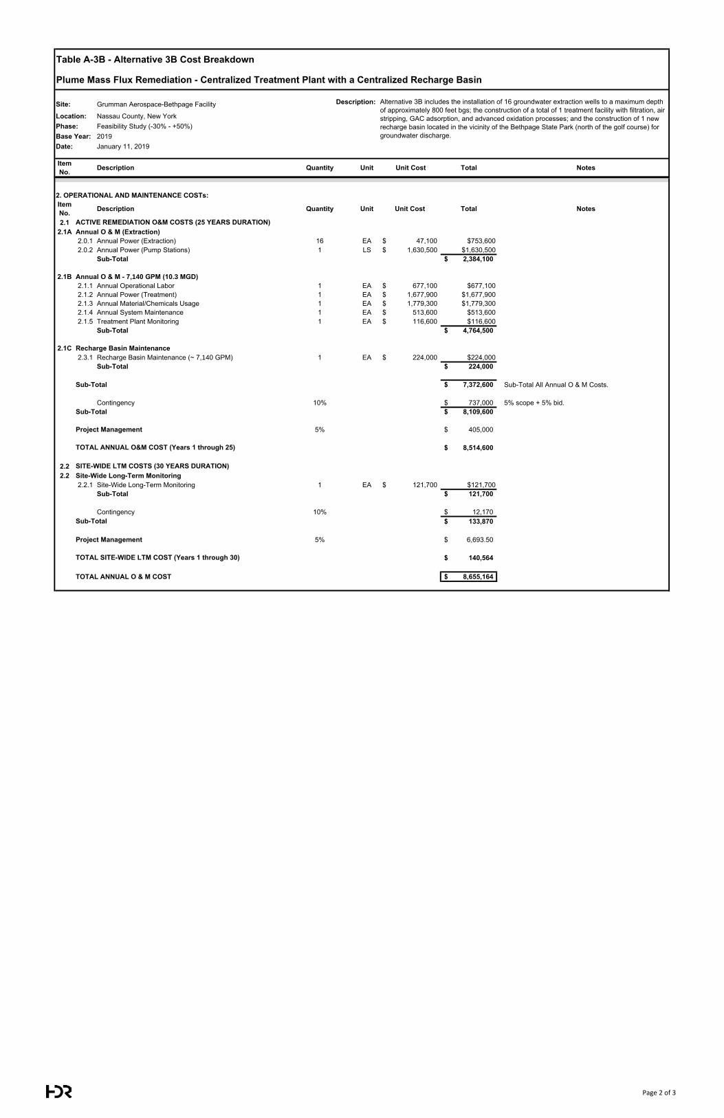
Table A-3B - Alternative 3B Cost Breakdown
Plume Mass Flux Remediation - Centralized Treatment Plant with a Centralized Recharge Basin
Site: Grumman Aerospace-Bethpage Facility Description:
Location: Nassau County, New YorkPhase: Feasibility Study (-30% - +50%)Base Year: 2019Date: January 11, 2019
Item No. Description Quantity Unit Unit Cost Total Notes
Alternative 3B includes the installation of 16 groundwater extraction wells to a maximum depth of approximately 800 feet bgs; the construction of a total of 1 treatment facility with filtration, air stripping, GAC adsorption, and advanced oxidation processes; and the construction of 1 new recharge basin located in the vicinity of the Bethpage State Park (north of the golf course) for groundwater discharge.
2. OPERATIONAL AND MAINTENANCE COSTs:Item No. Description Quantity Unit Unit Cost Total Notes
2.12.1A Annual O & M (Extraction)
2.0.1 Annual Power (Extraction) 16 EA 47,100$ $753,6002.0.2 Annual Power (Pump Stations) 1 LS 1,630,500$ $1,630,500
Sub-Total 2,384,100$
2.1B Annual O & M - 7,140 GPM (10.3 MGD)2.1.1 Annual Operational Labor 1 EA 677,100$ $677,1002.1.2 Annual Power (Treatment) 1 EA 1,677,900$ $1,677,9002.1.3 Annual Material/Chemicals Usage 1 EA 1,779,300$ $1,779,3002.1.4 Annual System Maintenance 1 EA 513,600$ $513,6002.1.5 Treatment Plant Monitoring 1 EA 116,600$ $116,600
Sub-Total 4,764,500$
2.1C Recharge Basin Maintenance 2.3.1 Recharge Basin Maintenance (~ 7,140 GPM) 1 EA 224,000$ $224,000
Sub-Total 224,000$
Sub-Total 7,372,600$ Sub-Total All Annual O & M Costs.
Contingency 10% 737,000$ 5% scope + 5% bid.Sub-Total 8,109,600$
Project Management 5% 405,000$
8,514,600$
2.22.2 Site-Wide Long-Term Monitoring
2.2.1 Site-Wide Long-Term Monitoring 1 EA 121,700$ $121,700Sub-Total 121,700$
Contingency 10% 12,170$ 133,870$
Project Management 5% 6,693.50$
140,564$
TOTAL ANNUAL O & M COST 8,655,164$
TOTAL SITE-WIDE LTM COST (Years 1 through 30)
ACTIVE REMEDIATION O&M COSTS (25 YEARS DURATION)
SITE-WIDE LTM COSTS (30 YEARS DURATION)
TOTAL ANNUAL O&M COST (Years 1 through 25)
Sub-Total
Page 2 of 3
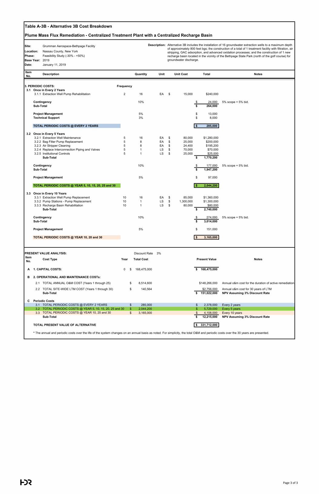
Table A-3B - Alternative 3B Cost Breakdown
Plume Mass Flux Remediation - Centralized Treatment Plant with a Centralized Recharge Basin
Site: Grumman Aerospace-Bethpage Facility Description:
Location: Nassau County, New YorkPhase: Feasibility Study (-30% - +50%)Base Year: 2019Date: January 11, 2019
Item No. Description Quantity Unit Unit Cost Total Notes
Alternative 3B includes the installation of 16 groundwater extraction wells to a maximum depth of approximately 800 feet bgs; the construction of a total of 1 treatment facility with filtration, air stripping, GAC adsorption, and advanced oxidation processes; and the construction of 1 new recharge basin located in the vicinity of the Bethpage State Park (north of the golf course) for groundwater discharge.
3. PERIODIC COSTS: Frequency3.1 Once in Every 2 Years
3.1.1 Extraction Well Pump Rehabilitation 2 16 EA 15,000$ $240,000
Contingency 10% 24,000$ 5% scope + 5% bid.Sub-Total 264,000$
Project Management 5% 13,000$ Technical Support 3% 8,000$
TOTAL PERIODIC COSTS @ EVERY 2 YEARS 285,000$
3.2 Once in Every 5 Years3.2.1 Extraction Well Maintenance 5 16 EA 80,000$ $1,280,0003.2.2 Bag Filter Pump Replacement 5 8 EA 25,000$ $200,0003.2.3 Air Stripper Cleaning 5 8 EA 24,400$ $195,2003.2.4 Replace Interconnection Piping and Valves 5 1 LS 70,000$ $70,0003.2.5 Institutional Controls 5 1 LS 25,000$ $25,000
Sub-Total 1,770,200$
Contingency 10% 177,000$ 5% scope + 5% bid.Sub-Total 1,947,200$
Project Management 5% 97,000$
TOTAL PERIODIC COSTS @ YEAR 5, 10, 15, 20, 25 and 30 2,044,200$
3.3 Once in Every 10 Years3.3.1 Extraction Well Pump Replacement 10 16 EA 85,000$ $1,360,0003.3.2 Pump Stations - Pump Replacement 10 1 LS 1,300,000$ $1,300,0003.3.3 Recharge Basin Rehabilitation 10 1 LS 80,000$ $80,000
Sub-Total 2,740,000$
Contingency 10% 274,000$ 5% scope + 5% bid.Sub-Total 3,014,000$
Project Management 5% 151,000$
TOTAL PERIODIC COSTS @ YEAR 10, 20 and 30 3,165,000$
PRESENT VALUE ANALYSIS: Discount Rate 3% Interest Rate: 0%Item No. Cost Type Year Total Cost Present Value Notes
A 1. CAPITAL COSTS: 0 168,475,000$ 168,475,000$
B 2. OPERATIONAL AND MAINTENANCE COSTs:
2.1 TOTAL ANNUAL O&M COST (Years 1 through 25) 8,514,600$ $148,266,000 Annual o&m cost for the duration of active remediation
2.2 TOTAL SITE-WIDE LTM COST (Years 1 through 30) 140,564$ $2,756,000 Annual o&m cost for 30 years of LTMSub-Total 151,022,000$ NPV Assuming 3% Discount Rate
C Periodic Costs3.1 TOTAL PERIODIC COSTS @ EVERY 2 YEARS 285,000$ 2,378,000$ Every 2 years3.2 TOTAL PERIODIC COSTS @ YEAR 5, 10, 15, 20, 25 and 30 2,044,200$ 5,729,000$ Every 5 years3.3 TOTAL PERIODIC COSTS @ YEAR 10, 20 and 30 3,165,000$ 4,108,000$ Every 10 years
Sub-Total 12,215,000$ NPV Assuming 3% Discount Rate
TOTAL PRESENT VALUE OF ALTERNATIVE 331,712,000$
* The annual and periodic costs over the life of the system changes on an annual basis as noted. For simplicity, the total O&M and periodic costs over the 30 years are presented.
Page 3 of 3
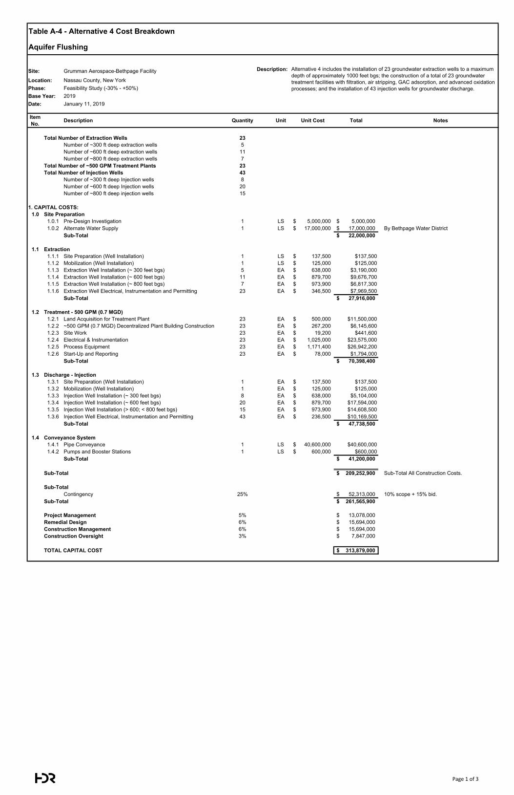
Table A-4 - Alternative 4 Cost Breakdown
Aquifer Flushing
Site: Grumman Aerospace-Bethpage Facility Description:
Location: Nassau County, New YorkPhase: Feasibility Study (-30% - +50%)Base Year: 2019Date: January 11, 2019
Item No. Description Quantity Unit Unit Cost Total Notes
Total Number of Extraction Wells 23Number of ~300 ft deep extraction wells 5Number of ~600 ft deep extraction wells 11Number of ~800 ft deep extraction wells 7
Total Number of ~500 GPM Treatment Plants 23Total Number of Injection Wells 43
Number of ~300 ft deep Injection wells 8Number of ~600 ft deep Injection wells 20Number of ~800 ft deep injection wells 15
1. CAPITAL COSTS:1.0 Site Preparation
1.0.1 Pre-Design Investigation 1 LS 5,000,000$ 5,000,000$ 1.0.2 Alternate Water Supply 1 LS 17,000,000$ 17,000,000$ By Bethpage Water District
Sub-Total 22,000,000$
1.1 Extraction1.1.1 Site Preparation (Well Installation) 1 LS 137,500$ $137,5001.1.2 Mobilization (Well Installation) 1 LS 125,000$ $125,0001.1.3 Extraction Well Installation (~ 300 feet bgs) 5 EA 638,000$ $3,190,0001.1.4 Extraction Well Installation (~ 600 feet bgs) 11 EA 879,700$ $9,676,7001.1.5 Extraction Well Installation (~ 800 feet bgs) 7 EA 973,900$ $6,817,3001.1.6 Extraction Well Electrical, Instrumentation and Permitting 23 EA 346,500$ $7,969,500
Sub-Total 27,916,000$
1.2 Treatment - 500 GPM (0.7 MGD)1.2.1 Land Acquisition for Treatment Plant 23 EA 500,000$ $11,500,0001.2.2 ~500 GPM (0.7 MGD) Decentralized Plant Building Construction 23 EA 267,200$ $6,145,6001.2.3 Site Work 23 EA 19,200$ $441,6001.2.4 Electrical & Instrumentation 23 EA 1,025,000$ $23,575,0001.2.5 Process Equipment 23 EA 1,171,400$ $26,942,2001.2.6 Start-Up and Reporting 23 EA 78,000$ $1,794,000
Sub-Total 70,398,400$
1.3 Discharge - Injection1.3.1 Site Preparation (Well Installation) 1 EA 137,500$ $137,5001.3.2 Mobilization (Well Installation) 1 EA 125,000$ $125,0001.3.3 Injection Well Installation (~ 300 feet bgs) 8 EA 638,000$ $5,104,0001.3.4 Injection Well Installation (~ 600 feet bgs) 20 EA 879,700$ $17,594,0001.3.5 Injection Well Installation (> 600; < 800 feet bgs) 15 EA 973,900$ $14,608,5001.3.6 Injection Well Electrical, Instrumentation and Permitting 43 EA 236,500$ $10,169,500
Sub-Total 47,738,500$
1.4 Conveyance System1.4.1 Pipe Conveyance 1 LS 40,600,000$ $40,600,0001.4.2 Pumps and Booster Stations 1 LS 600,000$ $600,000
Sub-Total 41,200,000$
Sub-Total 209,252,900$ Sub-Total All Construction Costs.
Sub-TotalContingency 25% 52,313,000$ 10% scope + 15% bid.
Sub-Total 261,565,900$
Project Management 5% 13,078,000$ Remedial Design 6% 15,694,000$ Construction Management 6% 15,694,000$ Construction Oversight 3% 7,847,000$
TOTAL CAPITAL COST 313,879,000$
Alternative 4 includes the installation of 23 groundwater extraction wells to a maximum depth of approximately 1000 feet bgs; the construction of a total of 23 groundwater treatment facilities with filtration, air stripping, GAC adsorption, and advanced oxidation processes; and the installation of 43 injection wells for groundwater discharge.
Page 1 of 3
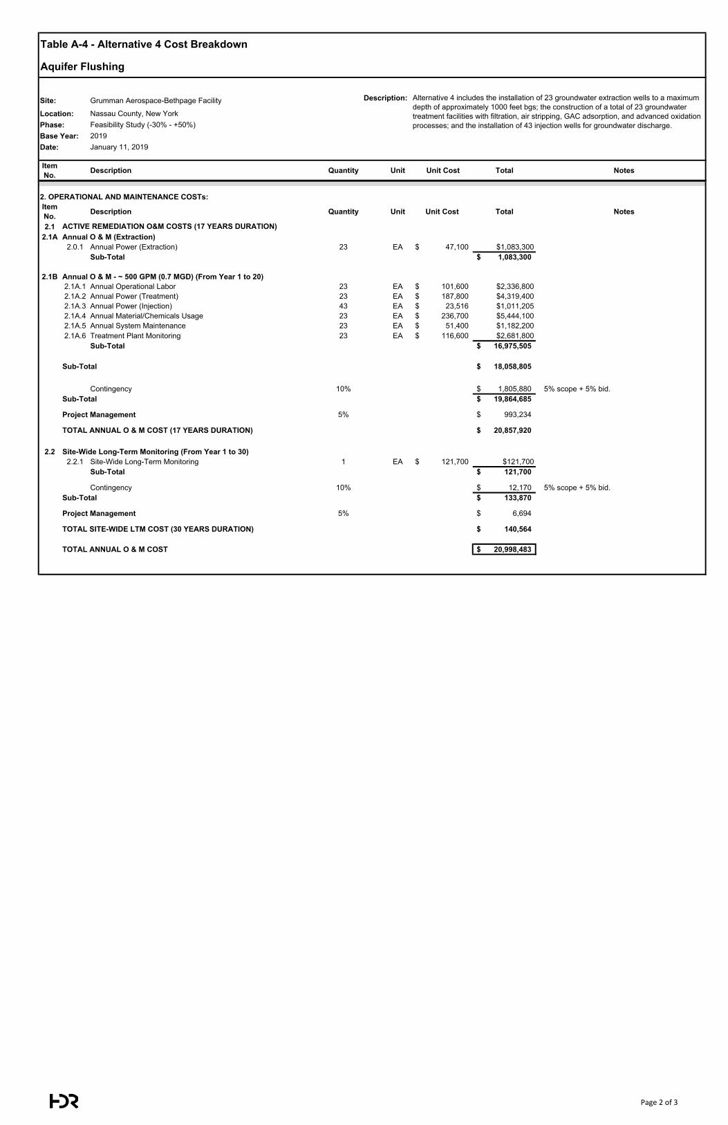
Table A-4 - Alternative 4 Cost Breakdown
Aquifer Flushing
Site: Grumman Aerospace-Bethpage Facility Description:
Location: Nassau County, New YorkPhase: Feasibility Study (-30% - +50%)Base Year: 2019Date: January 11, 2019
Item No. Description Quantity Unit Unit Cost Total Notes
Alternative 4 includes the installation of 23 groundwater extraction wells to a maximum depth of approximately 1000 feet bgs; the construction of a total of 23 groundwater treatment facilities with filtration, air stripping, GAC adsorption, and advanced oxidation processes; and the installation of 43 injection wells for groundwater discharge.
2. OPERATIONAL AND MAINTENANCE COSTs:Item No. Description Quantity Unit Unit Cost Total Notes
2.12.1A Annual O & M (Extraction)
2.0.1 Annual Power (Extraction) 23 EA 47,100$ $1,083,300Sub-Total 1,083,300$
2.1B Annual O & M - ~ 500 GPM (0.7 MGD) (From Year 1 to 20)2.1A.1 Annual Operational Labor 23 EA 101,600$ $2,336,8002.1A.2 Annual Power (Treatment) 23 EA 187,800$ $4,319,4002.1A.3 Annual Power (Injection) 43 EA 23,516$ $1,011,2052.1A.4 Annual Material/Chemicals Usage 23 EA 236,700$ $5,444,1002.1A.5 Annual System Maintenance 23 EA 51,400$ $1,182,2002.1A.6 Treatment Plant Monitoring 23 EA 116,600$ $2,681,800
Sub-Total 16,975,505$
Sub-Total 18,058,805$
Contingency 10% 1,805,880$ 5% scope + 5% bid.Sub-Total 19,864,685$
Project Management 5% 993,234$
TOTAL ANNUAL O & M COST (17 YEARS DURATION) 20,857,920$
2.2 Site-Wide Long-Term Monitoring (From Year 1 to 30)2.2.1 Site-Wide Long-Term Monitoring 1 EA 121,700$ $121,700
Sub-Total 121,700$
Contingency 10% 12,170$ 5% scope + 5% bid.Sub-Total 133,870$
Project Management 5% 6,694$
TOTAL SITE-WIDE LTM COST (30 YEARS DURATION) 140,564$
TOTAL ANNUAL O & M COST 20,998,483$
ACTIVE REMEDIATION O&M COSTS (17 YEARS DURATION)
Page 2 of 3
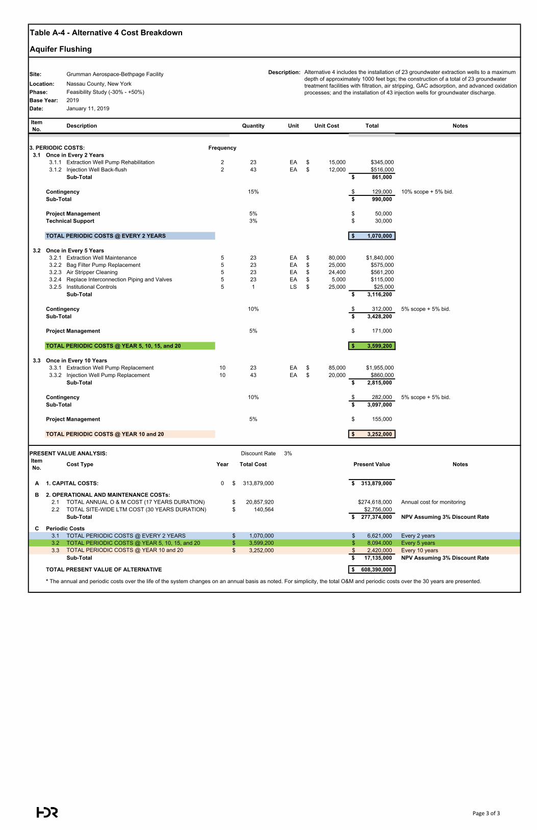
Table A-4 - Alternative 4 Cost Breakdown
Aquifer Flushing
Site: Grumman Aerospace-Bethpage Facility Description:
Location: Nassau County, New YorkPhase: Feasibility Study (-30% - +50%)Base Year: 2019Date: January 11, 2019
Item No. Description Quantity Unit Unit Cost Total Notes
Alternative 4 includes the installation of 23 groundwater extraction wells to a maximum depth of approximately 1000 feet bgs; the construction of a total of 23 groundwater treatment facilities with filtration, air stripping, GAC adsorption, and advanced oxidation processes; and the installation of 43 injection wells for groundwater discharge.
3. PERIODIC COSTS: Frequency3.1 Once in Every 2 Years
3.1.1 Extraction Well Pump Rehabilitation 2 23 EA 15,000$ $345,0003.1.2 Injection Well Back-flush 2 43 EA 12,000$ $516,000
Sub-Total 861,000$
Contingency 15% 129,000$ 10% scope + 5% bid.Sub-Total 990,000$
Project Management 5% 50,000$ Technical Support 3% 30,000$
TOTAL PERIODIC COSTS @ EVERY 2 YEARS 1,070,000$
3.2 Once in Every 5 Years3.2.1 Extraction Well Maintenance 5 23 EA 80,000$ $1,840,0003.2.2 Bag Filter Pump Replacement 5 23 EA 25,000$ $575,0003.2.3 Air Stripper Cleaning 5 23 EA 24,400$ $561,2003.2.4 Replace Interconnection Piping and Valves 5 23 EA 5,000$ $115,0003.2.5 Institutional Controls 5 1 LS 25,000$ $25,000
Sub-Total 3,116,200$
Contingency 10% 312,000$ 5% scope + 5% bid.Sub-Total 3,428,200$
Project Management 5% 171,000$
TOTAL PERIODIC COSTS @ YEAR 5, 10, 15, and 20 3,599,200$
3.3 Once in Every 10 Years3.3.1 Extraction Well Pump Replacement 10 23 EA 85,000$ $1,955,0003.3.2 Injection Well Pump Replacement 10 43 EA 20,000$ $860,000
Sub-Total 2,815,000$
Contingency 10% 282,000$ 5% scope + 5% bid.Sub-Total 3,097,000$
Project Management 5% 155,000$
TOTAL PERIODIC COSTS @ YEAR 10 and 20 3,252,000$
PRESENT VALUE ANALYSIS: Discount Rate 3% Interest Rate: 0%Item No. Cost Type Year Total Cost Present Value Notes
A 1. CAPITAL COSTS: 0 313,879,000$ 313,879,000$
B 2. OPERATIONAL AND MAINTENANCE COSTs:2.1 TOTAL ANNUAL O & M COST (17 YEARS DURATION) 20,857,920$ $274,618,000 Annual cost for monitoring2.2 TOTAL SITE-WIDE LTM COST (30 YEARS DURATION) 140,564$ $2,756,000
Sub-Total 277,374,000$ NPV Assuming 3% Discount Rate
C Periodic Costs3.1 TOTAL PERIODIC COSTS @ EVERY 2 YEARS 1,070,000$ 6,621,000$ Every 2 years3.2 TOTAL PERIODIC COSTS @ YEAR 5, 10, 15, and 20 3,599,200$ 8,094,000$ Every 5 years3.3 TOTAL PERIODIC COSTS @ YEAR 10 and 20 3,252,000$ 2,420,000$ Every 10 years
Sub-Total 17,135,000$ NPV Assuming 3% Discount Rate
TOTAL PRESENT VALUE OF ALTERNATIVE 608,390,000$
* The annual and periodic costs over the life of the system changes on an annual basis as noted. For simplicity, the total O&M and periodic costs over the 30 years are presented.
Page 3 of 3
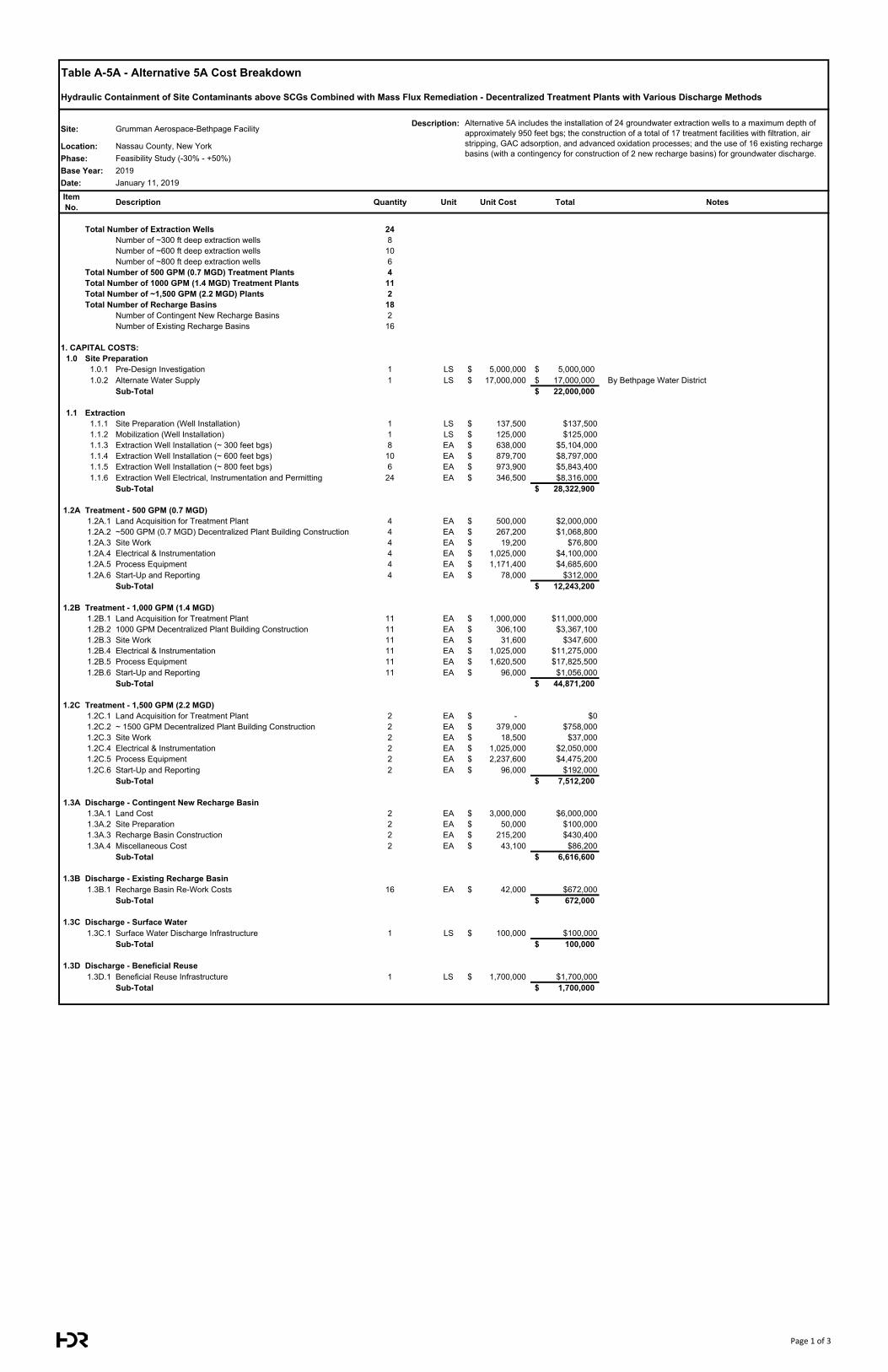
Table A-5A - Alternative 5A Cost Breakdown
Hydraulic Containment of Site Contaminants above SCGs Combined with Mass Flux Remediation - Decentralized Treatment Plants with Various Discharge Methods
Site: Grumman Aerospace-Bethpage FacilityDescription:
Location: Nassau County, New YorkPhase: Feasibility Study (-30% - +50%)Base Year: 2019Date: January 11, 2019
Item No. Description Quantity Unit Unit Cost Total Notes
Total Number of Extraction Wells 24Number of ~300 ft deep extraction wells 8Number of ~600 ft deep extraction wells 10Number of ~800 ft deep extraction wells 6
Total Number of 500 GPM (0.7 MGD) Treatment Plants 4Total Number of 1000 GPM (1.4 MGD) Treatment Plants 11Total Number of ~1,500 GPM (2.2 MGD) Plants 2Total Number of Recharge Basins 18
Number of Contingent New Recharge Basins 2Number of Existing Recharge Basins 16
1. CAPITAL COSTS:1.0 Site Preparation
1.0.1 Pre-Design Investigation 1 LS 5,000,000$ 5,000,000$ 1.0.2 Alternate Water Supply 1 LS 17,000,000$ 17,000,000$ By Bethpage Water District
Sub-Total 22,000,000$
1.1 Extraction1.1.1 Site Preparation (Well Installation) 1 LS 137,500$ $137,5001.1.2 Mobilization (Well Installation) 1 LS 125,000$ $125,0001.1.3 Extraction Well Installation (~ 300 feet bgs) 8 EA 638,000$ $5,104,0001.1.4 Extraction Well Installation (~ 600 feet bgs) 10 EA 879,700$ $8,797,0001.1.5 Extraction Well Installation (~ 800 feet bgs) 6 EA 973,900$ $5,843,4001.1.6 Extraction Well Electrical, Instrumentation and Permitting 24 EA 346,500$ $8,316,000
Sub-Total 28,322,900$
1.2A Treatment - 500 GPM (0.7 MGD)1.2A.1 Land Acquisition for Treatment Plant 4 EA 500,000$ $2,000,0001.2A.2 ~500 GPM (0.7 MGD) Decentralized Plant Building Construction 4 EA 267,200$ $1,068,8001.2A.3 Site Work 4 EA 19,200$ $76,8001.2A.4 Electrical & Instrumentation 4 EA 1,025,000$ $4,100,0001.2A.5 Process Equipment 4 EA 1,171,400$ $4,685,6001.2A.6 Start-Up and Reporting 4 EA 78,000$ $312,000
Sub-Total 12,243,200$
1.2B Treatment - 1,000 GPM (1.4 MGD)1.2B.1 Land Acquisition for Treatment Plant 11 EA 1,000,000$ $11,000,0001.2B.2 1000 GPM Decentralized Plant Building Construction 11 EA 306,100$ $3,367,1001.2B.3 Site Work 11 EA 31,600$ $347,6001.2B.4 Electrical & Instrumentation 11 EA 1,025,000$ $11,275,0001.2B.5 Process Equipment 11 EA 1,620,500$ $17,825,5001.2B.6 Start-Up and Reporting 11 EA 96,000$ $1,056,000
Sub-Total 44,871,200$
1.2C Treatment - 1,500 GPM (2.2 MGD)1.2C.1 Land Acquisition for Treatment Plant 2 EA -$ $01.2C.2 ~ 1500 GPM Decentralized Plant Building Construction 2 EA 379,000$ $758,0001.2C.3 Site Work 2 EA 18,500$ $37,0001.2C.4 Electrical & Instrumentation 2 EA 1,025,000$ $2,050,0001.2C.5 Process Equipment 2 EA 2,237,600$ $4,475,2001.2C.6 Start-Up and Reporting 2 EA 96,000$ $192,000
Sub-Total 7,512,200$
1.3A Discharge - Contingent New Recharge Basin1.3A.1 Land Cost 2 EA 3,000,000$ $6,000,0001.3A.2 Site Preparation 2 EA 50,000$ $100,0001.3A.3 Recharge Basin Construction 2 EA 215,200$ $430,4001.3A.4 Miscellaneous Cost 2 EA 43,100$ $86,200
Sub-Total 6,616,600$
1.3B Discharge - Existing Recharge Basin1.3B.1 Recharge Basin Re-Work Costs 16 EA 42,000$ $672,000
Sub-Total 672,000$
1.3C Discharge - Surface Water1.3C.1 Surface Water Discharge Infrastructure 1 LS 100,000$ $100,000
Sub-Total 100,000$
1.3D Discharge - Beneficial Reuse1.3D.1 Beneficial Reuse Infrastructure 1 LS 1,700,000$ $1,700,000
Sub-Total 1,700,000$
Alternative 5A includes the installation of 24 groundwater extraction wells to a maximum depth of approximately 950 feet bgs; the construction of a total of 17 treatment facilities with filtration, air stripping, GAC adsorption, and advanced oxidation processes; and the use of 16 existing recharge basins (with a contingency for construction of 2 new recharge basins) for groundwater discharge.
Page 1 of 3
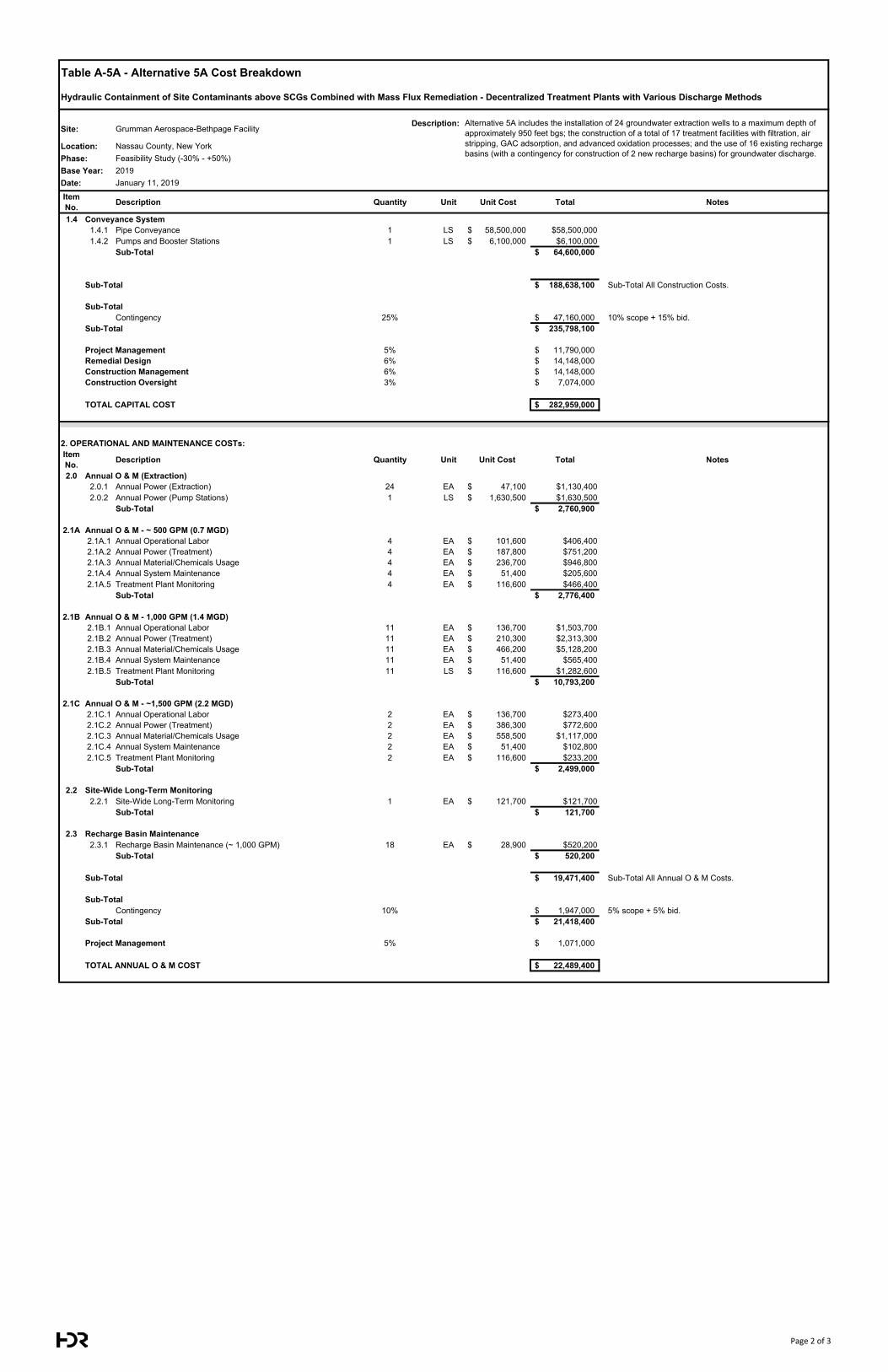
Table A-5A - Alternative 5A Cost Breakdown
Hydraulic Containment of Site Contaminants above SCGs Combined with Mass Flux Remediation - Decentralized Treatment Plants with Various Discharge Methods
Site: Grumman Aerospace-Bethpage FacilityDescription:
Location: Nassau County, New YorkPhase: Feasibility Study (-30% - +50%)Base Year: 2019Date: January 11, 2019
Item No. Description Quantity Unit Unit Cost Total Notes
Alternative 5A includes the installation of 24 groundwater extraction wells to a maximum depth of approximately 950 feet bgs; the construction of a total of 17 treatment facilities with filtration, air stripping, GAC adsorption, and advanced oxidation processes; and the use of 16 existing recharge basins (with a contingency for construction of 2 new recharge basins) for groundwater discharge.
1.4 Conveyance System1.4.1 Pipe Conveyance 1 LS 58,500,000$ $58,500,0001.4.2 Pumps and Booster Stations 1 LS 6,100,000$ $6,100,000
Sub-Total 64,600,000$
Sub-Total 188,638,100$ Sub-Total All Construction Costs.
Sub-TotalContingency 25% 47,160,000$ 10% scope + 15% bid.
Sub-Total 235,798,100$
Project Management 5% 11,790,000$ Remedial Design 6% 14,148,000$ Construction Management 6% 14,148,000$ Construction Oversight 3% 7,074,000$
TOTAL CAPITAL COST 282,959,000$
2. OPERATIONAL AND MAINTENANCE COSTs:Item No. Description Quantity Unit Unit Cost Total Notes
2.0 Annual O & M (Extraction)2.0.1 Annual Power (Extraction) 24 EA 47,100$ $1,130,4002.0.2 Annual Power (Pump Stations) 1 LS 1,630,500$ $1,630,500
Sub-Total 2,760,900$
2.1A Annual O & M - ~ 500 GPM (0.7 MGD)2.1A.1 Annual Operational Labor 4 EA 101,600$ $406,4002.1A.2 Annual Power (Treatment) 4 EA 187,800$ $751,2002.1A.3 Annual Material/Chemicals Usage 4 EA 236,700$ $946,8002.1A.4 Annual System Maintenance 4 EA 51,400$ $205,6002.1A.5 Treatment Plant Monitoring 4 EA 116,600$ $466,400
Sub-Total 2,776,400$
2.1B Annual O & M - 1,000 GPM (1.4 MGD)2.1B.1 Annual Operational Labor 11 EA 136,700$ $1,503,7002.1B.2 Annual Power (Treatment) 11 EA 210,300$ $2,313,3002.1B.3 Annual Material/Chemicals Usage 11 EA 466,200$ $5,128,2002.1B.4 Annual System Maintenance 11 EA 51,400$ $565,4002.1B.5 Treatment Plant Monitoring 11 LS 116,600$ $1,282,600
Sub-Total 10,793,200$
2.1C Annual O & M - ~1,500 GPM (2.2 MGD)2.1C.1 Annual Operational Labor 2 EA 136,700$ $273,4002.1C.2 Annual Power (Treatment) 2 EA 386,300$ $772,6002.1C.3 Annual Material/Chemicals Usage 2 EA 558,500$ $1,117,0002.1C.4 Annual System Maintenance 2 EA 51,400$ $102,8002.1C.5 Treatment Plant Monitoring 2 EA 116,600$ $233,200
Sub-Total 2,499,000$
2.2 Site-Wide Long-Term Monitoring2.2.1 Site-Wide Long-Term Monitoring 1 EA 121,700$ $121,700
Sub-Total 121,700$
2.3 Recharge Basin Maintenance2.3.1 Recharge Basin Maintenance (~ 1,000 GPM) 18 EA 28,900$ $520,200
Sub-Total 520,200$
Sub-Total 19,471,400$ Sub-Total All Annual O & M Costs.
Sub-TotalContingency 10% 1,947,000$ 5% scope + 5% bid.
Sub-Total 21,418,400$
Project Management 5% 1,071,000$
TOTAL ANNUAL O & M COST 22,489,400$
Page 2 of 3
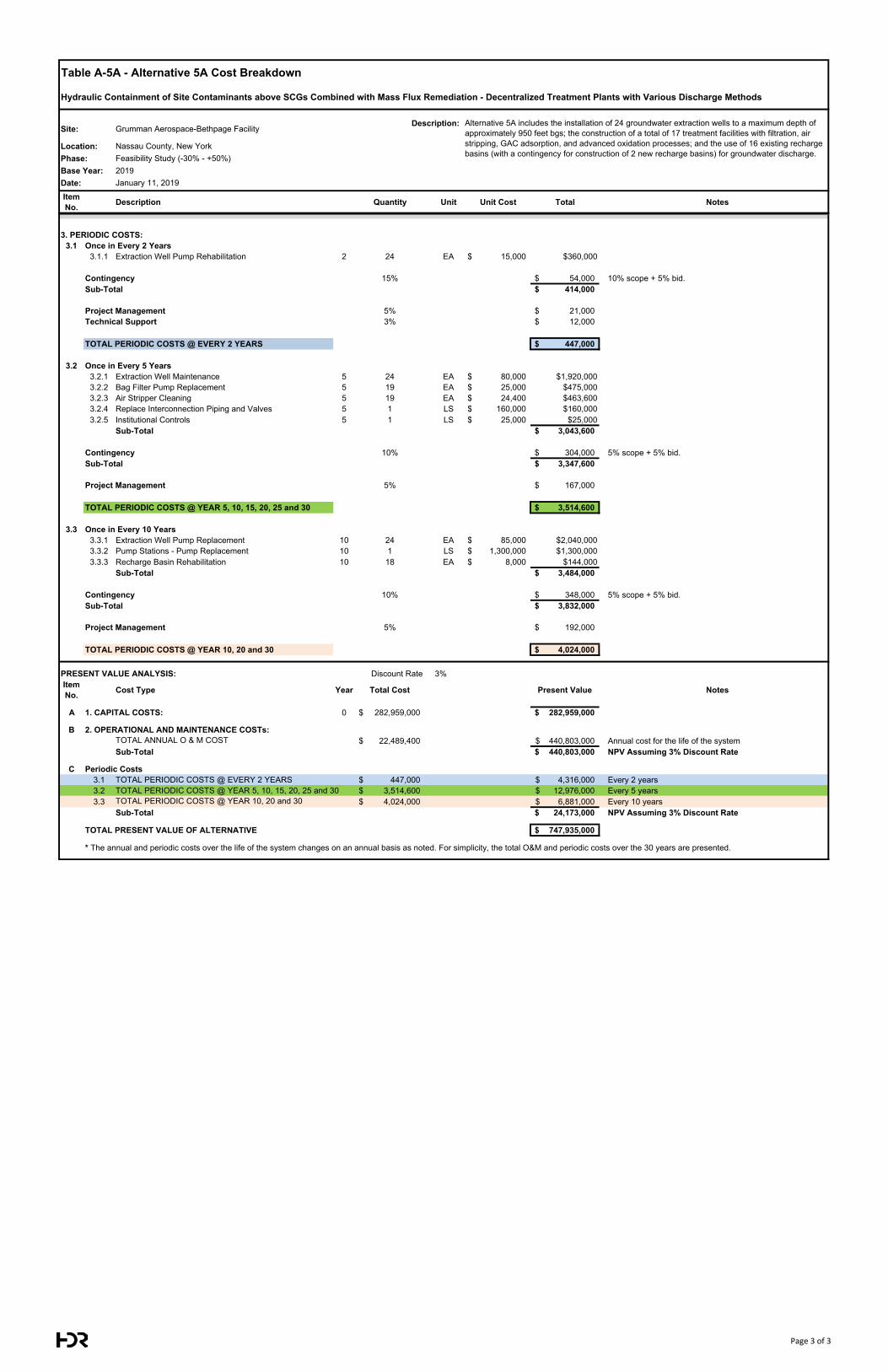
Table A-5A - Alternative 5A Cost Breakdown
Hydraulic Containment of Site Contaminants above SCGs Combined with Mass Flux Remediation - Decentralized Treatment Plants with Various Discharge Methods
Site: Grumman Aerospace-Bethpage FacilityDescription:
Location: Nassau County, New YorkPhase: Feasibility Study (-30% - +50%)Base Year: 2019Date: January 11, 2019
Item No. Description Quantity Unit Unit Cost Total Notes
Alternative 5A includes the installation of 24 groundwater extraction wells to a maximum depth of approximately 950 feet bgs; the construction of a total of 17 treatment facilities with filtration, air stripping, GAC adsorption, and advanced oxidation processes; and the use of 16 existing recharge basins (with a contingency for construction of 2 new recharge basins) for groundwater discharge.
3. PERIODIC COSTS:3.1 Once in Every 2 Years
3.1.1 Extraction Well Pump Rehabilitation 2 24 EA 15,000$ $360,000
Contingency 15% 54,000$ 10% scope + 5% bid.Sub-Total 414,000$
Project Management 5% 21,000$ Technical Support 3% 12,000$
TOTAL PERIODIC COSTS @ EVERY 2 YEARS 447,000$
3.2 Once in Every 5 Years3.2.1 Extraction Well Maintenance 5 24 EA 80,000$ $1,920,0003.2.2 Bag Filter Pump Replacement 5 19 EA 25,000$ $475,0003.2.3 Air Stripper Cleaning 5 19 EA 24,400$ $463,6003.2.4 Replace Interconnection Piping and Valves 5 1 LS 160,000$ $160,0003.2.5 Institutional Controls 5 1 LS 25,000$ $25,000
Sub-Total 3,043,600$
Contingency 10% 304,000$ 5% scope + 5% bid.Sub-Total 3,347,600$
Project Management 5% 167,000$
TOTAL PERIODIC COSTS @ YEAR 5, 10, 15, 20, 25 and 30 3,514,600$
3.3 Once in Every 10 Years3.3.1 Extraction Well Pump Replacement 10 24 EA 85,000$ $2,040,0003.3.2 Pump Stations - Pump Replacement 10 1 LS 1,300,000$ $1,300,0003.3.3 Recharge Basin Rehabilitation 10 18 EA 8,000$ $144,000
Sub-Total 3,484,000$
Contingency 10% 348,000$ 5% scope + 5% bid.Sub-Total 3,832,000$
Project Management 5% 192,000$
TOTAL PERIODIC COSTS @ YEAR 10, 20 and 30 4,024,000$
PRESENT VALUE ANALYSIS: Discount Rate 3% Interest Rate: 0%Item No. Cost Type Year Total Cost Present Value Notes
A 1. CAPITAL COSTS: 0 282,959,000$ 282,959,000$
B 2. OPERATIONAL AND MAINTENANCE COSTs:TOTAL ANNUAL O & M COST 22,489,400$ 440,803,000$ Annual cost for the life of the systemSub-Total 440,803,000$ NPV Assuming 3% Discount Rate
C Periodic Costs3.1 TOTAL PERIODIC COSTS @ EVERY 2 YEARS 447,000$ 4,316,000$ Every 2 years3.2 TOTAL PERIODIC COSTS @ YEAR 5, 10, 15, 20, 25 and 30 3,514,600$ 12,976,000$ Every 5 years3.3 TOTAL PERIODIC COSTS @ YEAR 10, 20 and 30 4,024,000$ 6,881,000$ Every 10 years
Sub-Total 24,173,000$ NPV Assuming 3% Discount Rate
TOTAL PRESENT VALUE OF ALTERNATIVE 747,935,000$
* The annual and periodic costs over the life of the system changes on an annual basis as noted. For simplicity, the total O&M and periodic costs over the 30 years are presented.
Page 3 of 3
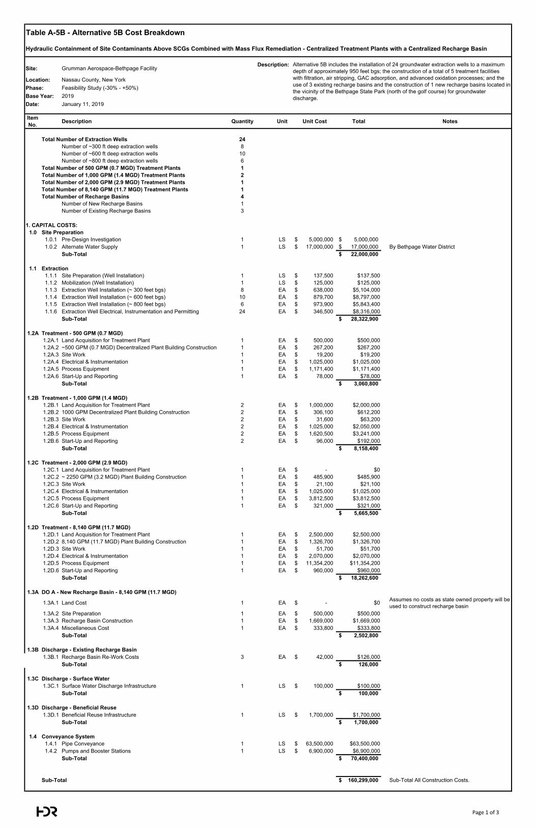
Table A-5B - Alternative 5B Cost Breakdown
Hydraulic Containment of Site Contaminants Above SCGs Combined with Mass Flux Remediation - Centralized Treatment Plants with a Centralized Recharge Basin
Site: Grumman Aerospace-Bethpage FacilityDescription:
Location: Nassau County, New YorkPhase: Feasibility Study (-30% - +50%)Base Year: 2019Date: January 11, 2019
Item No. Description Quantity Unit Unit Cost Total Notes
Total Number of Extraction Wells 24Number of ~300 ft deep extraction wells 8Number of ~600 ft deep extraction wells 10Number of ~800 ft deep extraction wells 6
Total Number of 500 GPM (0.7 MGD) Treatment Plants 1Total Number of 1,000 GPM (1.4 MGD) Treatment Plants 2Total Number of 2,000 GPM (2.9 MGD) Treatment Plants 1Total Number of 8,140 GPM (11.7 MGD) Treatment Plants 1Total Number of Recharge Basins 4
Number of New Recharge Basins 1Number of Existing Recharge Basins 3
1. CAPITAL COSTS:1.0 Site Preparation
1.0.1 Pre-Design Investigation 1 LS 5,000,000$ 5,000,000$ 1.0.2 Alternate Water Supply 1 LS 17,000,000$ 17,000,000$ By Bethpage Water District
Sub-Total 22,000,000$
1.1 Extraction1.1.1 Site Preparation (Well Installation) 1 LS 137,500$ $137,5001.1.2 Mobilization (Well Installation) 1 LS 125,000$ $125,0001.1.3 Extraction Well Installation (~ 300 feet bgs) 8 EA 638,000$ $5,104,0001.1.4 Extraction Well Installation (~ 600 feet bgs) 10 EA 879,700$ $8,797,0001.1.5 Extraction Well Installation (~ 800 feet bgs) 6 EA 973,900$ $5,843,4001.1.6 Extraction Well Electrical, Instrumentation and Permitting 24 EA 346,500$ $8,316,000
Sub-Total 28,322,900$
1.2A Treatment - 500 GPM (0.7 MGD)1.2A.1 Land Acquisition for Treatment Plant 1 EA 500,000$ $500,0001.2A.2 ~500 GPM (0.7 MGD) Decentralized Plant Building Construction 1 EA 267,200$ $267,2001.2A.3 Site Work 1 EA 19,200$ $19,2001.2A.4 Electrical & Instrumentation 1 EA 1,025,000$ $1,025,0001.2A.5 Process Equipment 1 EA 1,171,400$ $1,171,4001.2A.6 Start-Up and Reporting 1 EA 78,000$ $78,000
Sub-Total 3,060,800$
1.2B Treatment - 1,000 GPM (1.4 MGD)1.2B.1 Land Acquisition for Treatment Plant 2 EA 1,000,000$ $2,000,0001.2B.2 1000 GPM Decentralized Plant Building Construction 2 EA 306,100$ $612,2001.2B.3 Site Work 2 EA 31,600$ $63,2001.2B.4 Electrical & Instrumentation 2 EA 1,025,000$ $2,050,0001.2B.5 Process Equipment 2 EA 1,620,500$ $3,241,0001.2B.6 Start-Up and Reporting 2 EA 96,000$ $192,000
Sub-Total 8,158,400$
1.2C Treatment - 2,000 GPM (2.9 MGD)1.2C.1 Land Acquisition for Treatment Plant 1 EA -$ $01.2C.2 ~ 2250 GPM (3.2 MGD) Plant Building Construction 1 EA 485,900$ $485,9001.2C.3 Site Work 1 EA 21,100$ $21,1001.2C.4 Electrical & Instrumentation 1 EA 1,025,000$ $1,025,0001.2C.5 Process Equipment 1 EA 3,812,500$ $3,812,5001.2C.6 Start-Up and Reporting 1 EA 321,000$ $321,000
Sub-Total 5,665,500$
1.2D Treatment - 8,140 GPM (11.7 MGD)1.2D.1 Land Acquisition for Treatment Plant 1 EA 2,500,000$ $2,500,0001.2D.2 8,140 GPM (11.7 MGD) Plant Building Construction 1 EA 1,326,700$ $1,326,7001.2D.3 Site Work 1 EA 51,700$ $51,7001.2D.4 Electrical & Instrumentation 1 EA 2,070,000$ $2,070,0001.2D.5 Process Equipment 1 EA 11,354,200$ $11,354,2001.2D.6 Start-Up and Reporting 1 EA 960,000$ $960,000
Sub-Total 18,262,600$
1.3A DO A - New Recharge Basin - 8,140 GPM (11.7 MGD)
1.3A.1 Land Cost 1 EA -$ $0 Assumes no costs as state owned property will be used to construct recharge basin
1.3A.2 Site Preparation 1 EA 500,000$ $500,0001.3A.3 Recharge Basin Construction 1 EA 1,669,000$ $1,669,0001.3A.4 Miscellaneous Cost 1 EA 333,800$ $333,800
Sub-Total 2,502,800$
1.3B Discharge - Existing Recharge Basin1.3B.1 Recharge Basin Re-Work Costs 3 EA 42,000$ $126,000
Sub-Total 126,000$
1.3C Discharge - Surface Water1.3C.1 Surface Water Discharge Infrastructure 1 LS 100,000$ $100,000
Sub-Total 100,000$
1.3D Discharge - Beneficial Reuse1.3D.1 Beneficial Reuse Infrastructure 1 LS 1,700,000$ $1,700,000
Sub-Total 1,700,000$
1.4 Conveyance System1.4.1 Pipe Conveyance 1 LS 63,500,000$ $63,500,0001.4.2 Pumps and Booster Stations 1 LS 6,900,000$ $6,900,000
Sub-Total 70,400,000$
Sub-Total 160,299,000$ Sub-Total All Construction Costs.
Alternative 5B includes the installation of 24 groundwater extraction wells to a maximum depth of approximately 950 feet bgs; the construction of a total of 5 treatment facilities with filtration, air stripping, GAC adsorption, and advanced oxidation processes; and the use of 3 existing recharge basins and the construction of 1 new recharge basins located in the vicinity of the Bethpage State Park (north of the golf course) for groundwater discharge.
Page 1 of 3
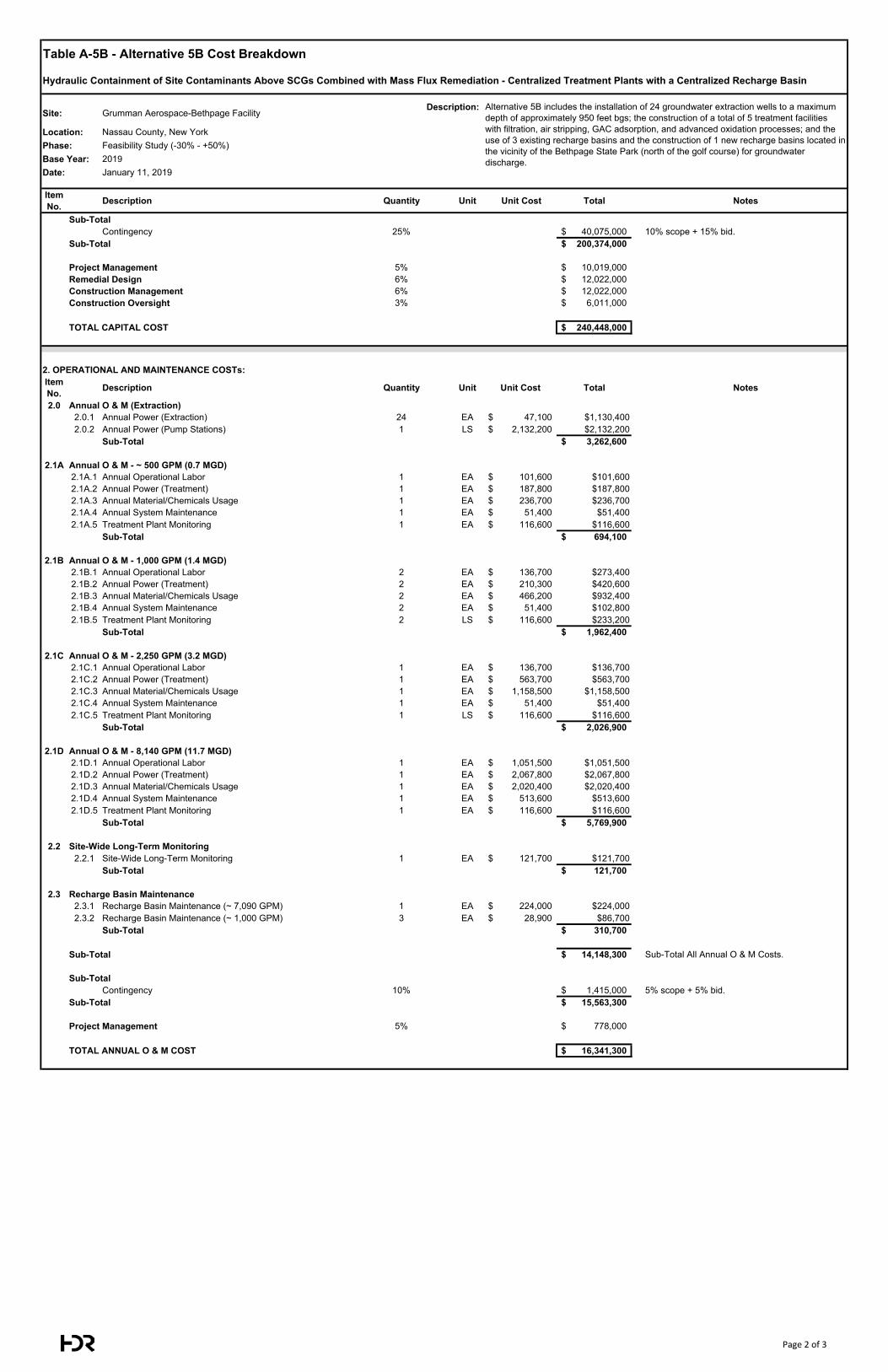
Table A-5B - Alternative 5B Cost Breakdown
Hydraulic Containment of Site Contaminants Above SCGs Combined with Mass Flux Remediation - Centralized Treatment Plants with a Centralized Recharge Basin
Site: Grumman Aerospace-Bethpage FacilityDescription:
Location: Nassau County, New YorkPhase: Feasibility Study (-30% - +50%)Base Year: 2019Date: January 11, 2019
Item No. Description Quantity Unit Unit Cost Total Notes
Alternative 5B includes the installation of 24 groundwater extraction wells to a maximum depth of approximately 950 feet bgs; the construction of a total of 5 treatment facilities with filtration, air stripping, GAC adsorption, and advanced oxidation processes; and the use of 3 existing recharge basins and the construction of 1 new recharge basins located in the vicinity of the Bethpage State Park (north of the golf course) for groundwater discharge.
Sub-TotalContingency 25% 40,075,000$ 10% scope + 15% bid.
Sub-Total 200,374,000$
Project Management 5% 10,019,000$ Remedial Design 6% 12,022,000$ Construction Management 6% 12,022,000$ Construction Oversight 3% 6,011,000$
TOTAL CAPITAL COST 240,448,000$
2. OPERATIONAL AND MAINTENANCE COSTs:Item No. Description Quantity Unit Unit Cost Total Notes
2.0 Annual O & M (Extraction)2.0.1 Annual Power (Extraction) 24 EA 47,100$ $1,130,4002.0.2 Annual Power (Pump Stations) 1 LS 2,132,200$ $2,132,200
Sub-Total 3,262,600$
2.1A Annual O & M - ~ 500 GPM (0.7 MGD)2.1A.1 Annual Operational Labor 1 EA 101,600$ $101,6002.1A.2 Annual Power (Treatment) 1 EA 187,800$ $187,8002.1A.3 Annual Material/Chemicals Usage 1 EA 236,700$ $236,7002.1A.4 Annual System Maintenance 1 EA 51,400$ $51,4002.1A.5 Treatment Plant Monitoring 1 EA 116,600$ $116,600
Sub-Total 694,100$
2.1B Annual O & M - 1,000 GPM (1.4 MGD)2.1B.1 Annual Operational Labor 2 EA 136,700$ $273,4002.1B.2 Annual Power (Treatment) 2 EA 210,300$ $420,6002.1B.3 Annual Material/Chemicals Usage 2 EA 466,200$ $932,4002.1B.4 Annual System Maintenance 2 EA 51,400$ $102,8002.1B.5 Treatment Plant Monitoring 2 LS 116,600$ $233,200
Sub-Total 1,962,400$
2.1C Annual O & M - 2,250 GPM (3.2 MGD)2.1C.1 Annual Operational Labor 1 EA 136,700$ $136,7002.1C.2 Annual Power (Treatment) 1 EA 563,700$ $563,7002.1C.3 Annual Material/Chemicals Usage 1 EA 1,158,500$ $1,158,5002.1C.4 Annual System Maintenance 1 EA 51,400$ $51,4002.1C.5 Treatment Plant Monitoring 1 LS 116,600$ $116,600
Sub-Total 2,026,900$
2.1D Annual O & M - 8,140 GPM (11.7 MGD)2.1D.1 Annual Operational Labor 1 EA 1,051,500$ $1,051,5002.1D.2 Annual Power (Treatment) 1 EA 2,067,800$ $2,067,8002.1D.3 Annual Material/Chemicals Usage 1 EA 2,020,400$ $2,020,4002.1D.4 Annual System Maintenance 1 EA 513,600$ $513,6002.1D.5 Treatment Plant Monitoring 1 EA 116,600$ $116,600
Sub-Total 5,769,900$
2.2 Site-Wide Long-Term Monitoring2.2.1 Site-Wide Long-Term Monitoring 1 EA 121,700$ $121,700
Sub-Total 121,700$
2.3 Recharge Basin Maintenance2.3.1 Recharge Basin Maintenance (~ 7,090 GPM) 1 EA 224,000$ $224,0002.3.2 Recharge Basin Maintenance (~ 1,000 GPM) 3 EA 28,900$ $86,700
Sub-Total 310,700$
Sub-Total 14,148,300$ Sub-Total All Annual O & M Costs.
Sub-TotalContingency 10% 1,415,000$ 5% scope + 5% bid.
Sub-Total 15,563,300$
Project Management 5% 778,000$
TOTAL ANNUAL O & M COST 16,341,300$
Page 2 of 3
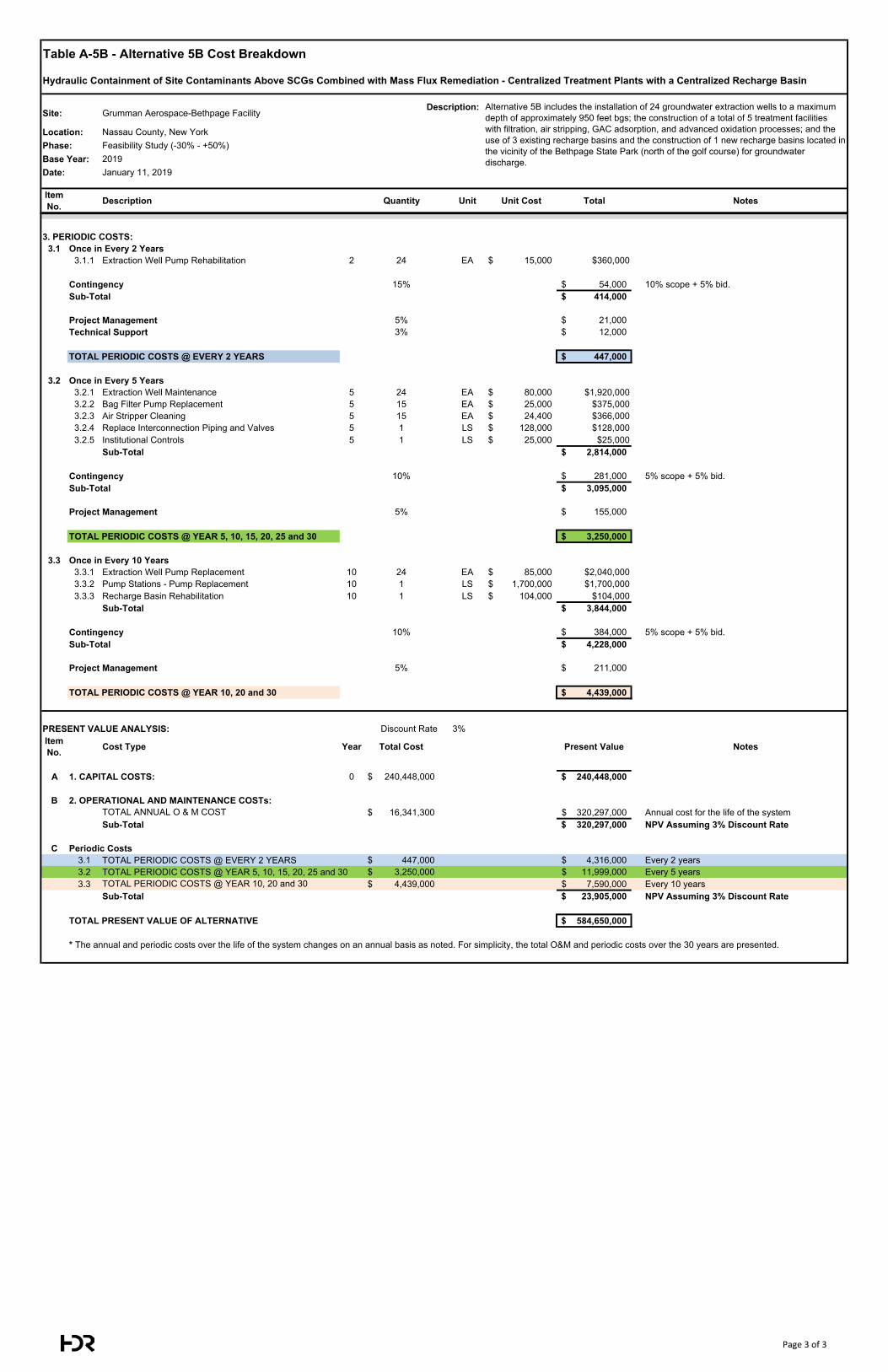
Table A-5B - Alternative 5B Cost Breakdown
Hydraulic Containment of Site Contaminants Above SCGs Combined with Mass Flux Remediation - Centralized Treatment Plants with a Centralized Recharge Basin
Site: Grumman Aerospace-Bethpage FacilityDescription:
Location: Nassau County, New YorkPhase: Feasibility Study (-30% - +50%)Base Year: 2019Date: January 11, 2019
Item No. Description Quantity Unit Unit Cost Total Notes
Alternative 5B includes the installation of 24 groundwater extraction wells to a maximum depth of approximately 950 feet bgs; the construction of a total of 5 treatment facilities with filtration, air stripping, GAC adsorption, and advanced oxidation processes; and the use of 3 existing recharge basins and the construction of 1 new recharge basins located in the vicinity of the Bethpage State Park (north of the golf course) for groundwater discharge.
3. PERIODIC COSTS:3.1 Once in Every 2 Years
3.1.1 Extraction Well Pump Rehabilitation 2 24 EA 15,000$ $360,000
Contingency 15% 54,000$ 10% scope + 5% bid.Sub-Total 414,000$
Project Management 5% 21,000$ Technical Support 3% 12,000$
TOTAL PERIODIC COSTS @ EVERY 2 YEARS 447,000$
3.2 Once in Every 5 Years3.2.1 Extraction Well Maintenance 5 24 EA 80,000$ $1,920,0003.2.2 Bag Filter Pump Replacement 5 15 EA 25,000$ $375,0003.2.3 Air Stripper Cleaning 5 15 EA 24,400$ $366,0003.2.4 Replace Interconnection Piping and Valves 5 1 LS 128,000$ $128,0003.2.5 Institutional Controls 5 1 LS 25,000$ $25,000
Sub-Total 2,814,000$
Contingency 10% 281,000$ 5% scope + 5% bid.Sub-Total 3,095,000$
Project Management 5% 155,000$
TOTAL PERIODIC COSTS @ YEAR 5, 10, 15, 20, 25 and 30 3,250,000$
3.3 Once in Every 10 Years3.3.1 Extraction Well Pump Replacement 10 24 EA 85,000$ $2,040,0003.3.2 Pump Stations - Pump Replacement 10 1 LS 1,700,000$ $1,700,0003.3.3 Recharge Basin Rehabilitation 10 1 LS 104,000$ $104,000
Sub-Total 3,844,000$
Contingency 10% 384,000$ 5% scope + 5% bid.Sub-Total 4,228,000$
Project Management 5% 211,000$
TOTAL PERIODIC COSTS @ YEAR 10, 20 and 30 4,439,000$
PRESENT VALUE ANALYSIS: Discount Rate 3% Interest Rate: 0%Item No. Cost Type Year Total Cost Present Value Notes
A 1. CAPITAL COSTS: 0 240,448,000$ 240,448,000$
B 2. OPERATIONAL AND MAINTENANCE COSTs:TOTAL ANNUAL O & M COST 16,341,300$ 320,297,000$ Annual cost for the life of the systemSub-Total 320,297,000$ NPV Assuming 3% Discount Rate
C Periodic Costs3.1 TOTAL PERIODIC COSTS @ EVERY 2 YEARS 447,000$ 4,316,000$ Every 2 years3.2 TOTAL PERIODIC COSTS @ YEAR 5, 10, 15, 20, 25 and 30 3,250,000$ 11,999,000$ Every 5 years3.3 TOTAL PERIODIC COSTS @ YEAR 10, 20 and 30 4,439,000$ 7,590,000$ Every 10 years
Sub-Total 23,905,000$ NPV Assuming 3% Discount Rate
TOTAL PRESENT VALUE OF ALTERNATIVE 584,650,000$
* The annual and periodic costs over the life of the system changes on an annual basis as noted. For simplicity, the total O&M and periodic costs over the 30 years are presented.
Page 3 of 3