Embed Size (px)
Citation preview

FY2014 Consigned Survey of the Introduction of Technologies to
Reduce Carbon Dioxide Generated by JCM Large-scale Energy
to Achieve a Low-Carbon Society in Asia
Feasible Study of the large scale CO2 reduction by
JCM program for DCS plant and co-generation system
in Thai International Airport
(Suvarnabhumi International Airport)
March 2015
Surveying Organization: Institute for Global Environmental Strategies
(IGES)

Table of Contents
Chapter 1 Background and Outline of the Survey ------------------------------------------------------1
1.1 Survey background
1.2 Work outline
Chapter 2 Systems Related to Energy Supply in Thailand ------------------------------------------3
2.1 SPPs, including international airports in Thailand
2.2 Power supply system
2.3 Participation of Japanese and overseas businesses in the SPP program
2.4 Industrial estates where SPPs supply power
2.5 Power generation ratio and direction of Thai power generation
2.6 Gas supply for power generation
2.7 Considerations regarding the direction of natural gas usage in Thailand
2.8 Current issues regarding SPPs in Thailand
Chapter 3 Applicable Carbon Dioxide Reduction Technologies for SPPs and Cogeneration
Systems at Suvarnabhumi Airport International Airport ------------------------------------------------14
3.1 SPP businesses targeted for the field survey
3.2 Gas turbine inlet cooling systems
3.3 Case examples of the application of gas turbine inlet cooling in Japan
3.4 Cogeneration system steam turbine output improvements
Chapter 4 Conditions for the Application of Inlet Cooling Systems -----------------------------31
4.1 Climate conditions in Thailand
4.2 Natural gas costs
4.3 Sales costs for generated power
4.4 IPP and SPP CO2 emissions per unit
4.5 Power CO2 emissions per unit in Thailand

Chapter 5 SPP Power Companies: Application of Inlet Cooling Systems for the Gas Turbine
Combined Cycle FS -----------------------------------------------------------------------------------------------------36
5.1 Studied SPP gas turbine combined cycle plants
5.2 Assessment of CO2 reduction amounts through the introduction of inlet cooling systems
5.3 SPP class gas turbine combined-cycle generation equipment: Assessment of the application
of inlet cooling systems
5.4 Points to note regarding SPP class gas turbine combined-cycle generation equipment inlet
cooling systems
Materials 5.1 Model Case for the Application of Gas Turbine Inlet Cooling for G Company
Product
Materials 5.2 Model Case for the Application of Gas Turbine Inlet Cooling for S Company
Product
Chapter 6 Drawing up of MRV Methodology (draft) and PDD (draft) ---------------------63
6.1 MRV Methodology (draft)
6.2 PDD (draft)
Chapter 7 Specific Funding, Construction, and Operation Plans, Implementation System, etc.
for Project Implementation----------------------------------------------------------------------------------------------74
7.1 Implementation Process of Gas Turbine Inlet Air Cooling system
7.2 Implementation System
7.3 Financing Plan
■Abbreviation ACM Approved Consolidated Methodology
AM Approved Methodology
BaU(BAU) Business-as-Usual
BOCM Bilateral Offset Credit Mechanism
C/P Counter Part
CDM Clean Development Mechanism
DOEs Designated Operational Entities
GHG Green House Gas
IPCC Intergovernmental Panel on Climate Change
JCM Joint Crediting Mechanism
JICA Japan International Cooperation Agency
MRV Measurement, Reporting, Verification
NAMAs Nationally Appropriate Mitigation Actions
NAPA National Adaptation Programmes of Action
NGO Non-Governmental Organizations
TPEs UNFCCC UN Framework Convention on Climate Change
PDD Project Design Document
PPP Public Private Partnership
QA/QC Quality Assurance/Quality Control
REDD+ Reducing Emissions from Deforestation and Forest Degradation PLUS
TOE Ton of Oil Equivalent
CHP Combined Heat and Power
DEDE Department of Alternative Energy Development and Efficiency
DEDP Department of Energy Development and Promotion
ECP Energy Conservation Plan
EGAT Electric Generating Authority of Thailand
EGCO Electricity Generating Company
EPPO Energy Policy Planning Office
ESI Electricity supply industry
GEF Global Environment Fund
IPP Independent Power Producers
LNG Liquid Natural Gas
LPG Liquid Petroleum Gas
MEA Metropolitan Electric Authority
NEPO National Energy Policy Office, Now EPPO.
NERC National Energy Regulatory Commission
NPC National Policy Committee
PCAF Power Consumer Assistant Fund
PEA Provincial Electric Authority
PTT Plc Petroleum Authority of Thailand Public Company
RATCH Ratchaburi Electricity Generating Holding
SPP Small Power Producer
TOD Time of Day
TOU Time of Use
VSPP Very Small Power Producer
VAT Value Added Tax
PTTEP PTT EXPLORATION AND PRODUCTION PUBLIC COMPANY LIMITED
CSP Combined Steam and Power
i
Final Report (Summary) on Contract Research for Introducing Technology of
Reducing Carbon Dioxide Emitted by JCM Large-Scale Energy Generation to Realize
Low Carbon Society in Asia in FY 2014
Feasible Study of the large scale CO2 reduction by JCM program for DCS
plant and co-generation system in Thai International Airport
(Suvarnabhumi International Airport) (Investigator: Institute for Global Environmental Strategies)
Partners Mitsubishi Heavy Industries, Ltd.
Mitsubishi Heavy Industries (Thailand) Ltd.
Country or area Thailand
Technical field Energy saving
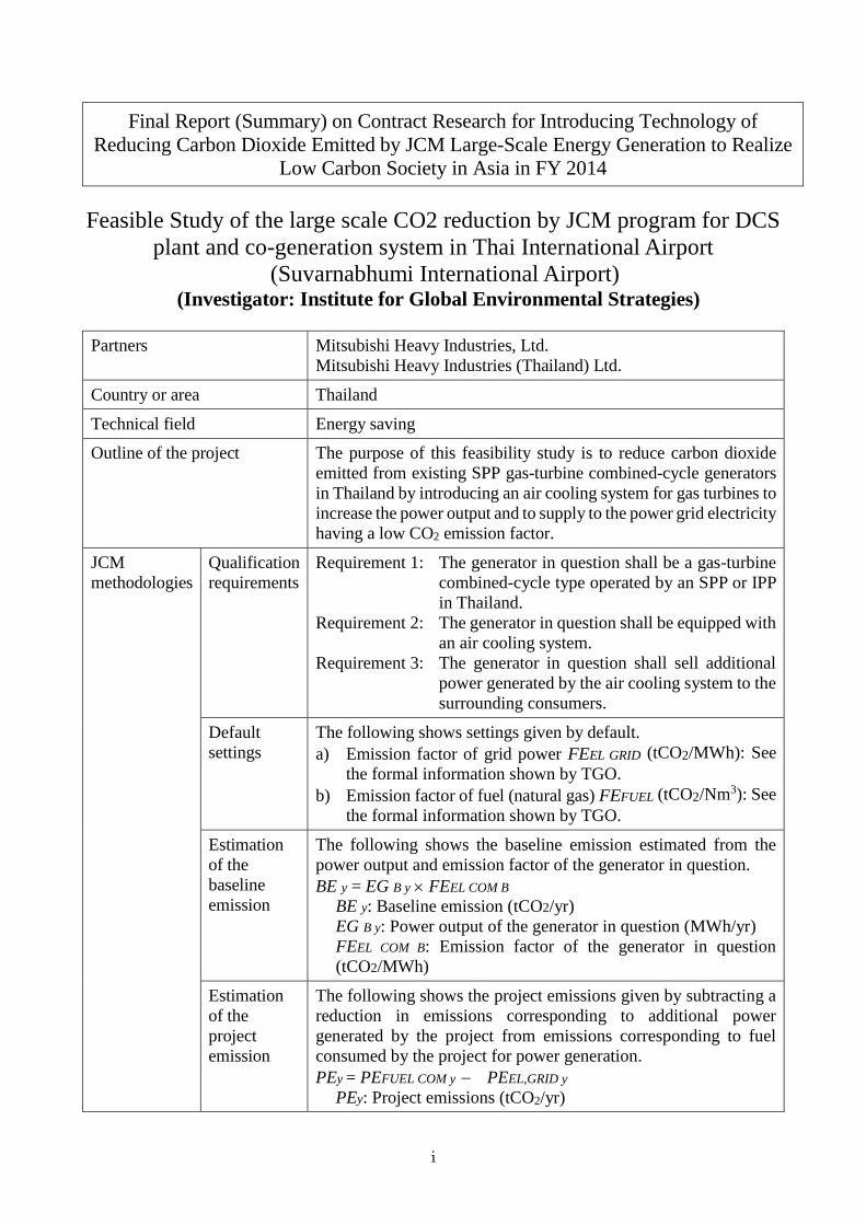
Outline of the project The purpose of this feasibility study is to reduce carbon dioxide
emitted from existing SPP gas-turbine combined-cycle generators
in Thailand by introducing an air cooling system for gas turbines to
increase the power output and to supply to the power grid electricity
having a low CO2 emission factor.
JCM
methodologies
Qualification
requirements
Requirement 1: The generator in question shall be a gas-turbine
combined-cycle type operated by an SPP or IPP
in Thailand.
Requirement 2: The generator in question shall be equipped with
an air cooling system.
Requirement 3: The generator in question shall sell additional
power generated by the air cooling system to the
surrounding consumers.
Default
settings
The following shows settings given by default.
a) Emission factor of grid power FEEL GRID (tCO2/MWh): See
the formal information shown by TGO.
b) Emission factor of fuel (natural gas) FEFUEL (tCO2/Nm3): See
the formal information shown by TGO.
Estimation
of the
baseline
emission
The following shows the baseline emission estimated from the
power output and emission factor of the generator in question.
BE y = EG B y FEEL COM B
BE y: Baseline emission (tCO2/yr)
EG B y: Power output of the generator in question (MWh/yr)
FEEL COM B: Emission factor of the generator in question
(tCO2/MWh)
Estimation
of the
project
emission
The following shows the project emissions given by subtracting a
reduction in emissions corresponding to additional power
generated by the project from emissions corresponding to fuel
consumed by the project for power generation.
PEy = PEFUEL COM y PEEL,GRID y
PEy: Project emissions (tCO2/yr)
ii
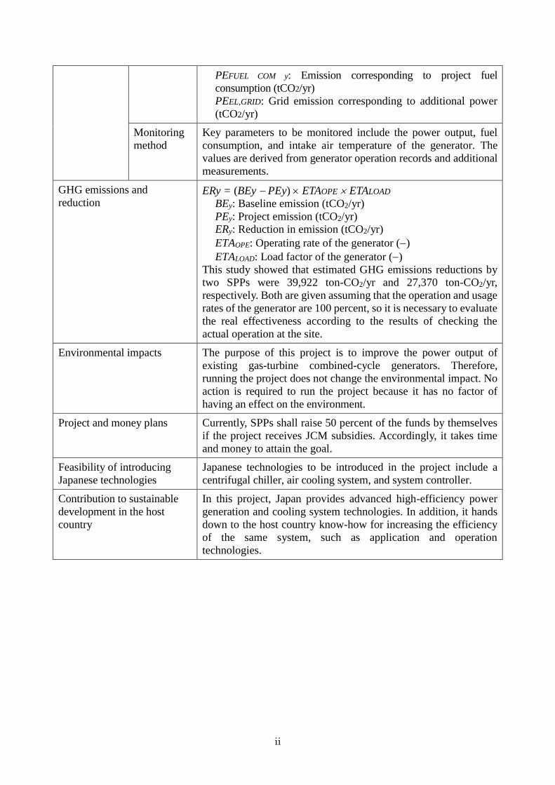
PEFUEL COM y: Emission corresponding to project fuel
consumption (tCO2/yr)
PEEL,GRID: Grid emission corresponding to additional power
(tCO2/yr)
Monitoring
method
Key parameters to be monitored include the power output, fuel
consumption, and intake air temperature of the generator. The
values are derived from generator operation records and additional
measurements.
GHG emissions and
reduction ERy = (BEy PEy) ETAOPE ETALOAD
BEy: Baseline emission (tCO2/yr)
PEy: Project emission (tCO2/yr)
ERy: Reduction in emission (tCO2/yr)
ETAOPE: Operating rate of the generator ()
ETALOAD: Load factor of the generator ()
This study showed that estimated GHG emissions reductions by
two SPPs were 39,922 ton-CO2/yr and 27,370 ton-CO2/yr,
respectively. Both are given assuming that the operation and usage
rates of the generator are 100 percent, so it is necessary to evaluate
the real effectiveness according to the results of checking the
actual operation at the site.
Environmental impacts The purpose of this project is to improve the power output of
existing gas-turbine combined-cycle generators. Therefore,
running the project does not change the environmental impact. No
action is required to run the project because it has no factor of
having an effect on the environment.
Project and money plans Currently, SPPs shall raise 50 percent of the funds by themselves
if the project receives JCM subsidies. Accordingly, it takes time
and money to attain the goal.
Feasibility of introducing
Japanese technologies
Japanese technologies to be introduced in the project include a
centrifugal chiller, air cooling system, and system controller.
Contribution to sustainable
development in the host
country
In this project, Japan provides advanced high-efficiency power
generation and cooling system technologies. In addition, it hands
down to the host country know-how for increasing the efficiency
of the same system, such as application and operation
technologies.

iii
Title: Contract Research for Introducing Technology of Reducing Carbon Dioxide
Emitted by JCM Large-Scale Energy Generation to Realize Low Carbon
Society in Asia in FY 2014
Feasibility Study of Applying Technology of Reducing Carbon Dioxide Emitted from
JCM Large-Scale Energy Generation to the Local Cooling and Cogeneration Plants of
the Suvarnabhumi Airport in Suwannaphum, Thailand
(Host country: Thailand)
Investigator: Institute for Global Environmental Strategies (IGES)
1. Research Organization
In this research, the investigator shown above works with the following two partners:
• Mitsubishi Heavy Industries, Ltd.: Main contractor in charge of research and study for reducing
carbon dioxide emissions and applying energy saving
technologies.
• MHI (Thailand) Ltd.: Co-ordination between SPPs in Thailand and Japanese side.
2. Research Overview
2.1. Outline of the Project
The main purpose of this research contracted with the Ministry of the Environment in Japan is to
conduct a survey for introducing technologies and plants that are used in power plants and energy-
consuming industries as well as that can reduce carbon dioxide emitted by large-scale energy
generation. The details of the survey are shown below.
• Research for introducing carbon dioxide reduction technologies to SPP cogeneration plants
In Thailand, SPPs (small power producers) operate large-scale cogeneration plant business by
installing a gas-turbine combined-cycle generator in an industrial park to supply electricity,
water, and steam at the site.
In this research, IGES not only introduces an air cooling system to such cogeneration plants to
reduce the carbon dioxide emission and energy cost but also estimates the investment cost to
check the effectiveness of the introduced system.
2.2. Current Situation of the Host Country
(1) SPPs including Thai international airports and SPP programs
The Thai government promotes systems for using energy effectively. In 1992, the “Regulations for
the purchase of power from small power producers (SPPs) for electricity generated from non-
conventional energy, waste, residual fuel, and co-generation” were enforced to reduce the import
and consumption of oil by encouraging the SPPs to use exhaust heat during power generation and
to regenerate energy for a rise in energy usage efficiency.
Some Thai international airports follow the regulations in order to generate electricity with a gas
turbine, to produce steam by using exhaust heat during power generation, to regenerate electricity

iv
with a steam turbine, and to produce cold water with the remaining steam and an absorption
refrigerator. They sell the resulting electricity to EGAT and other airports, so they are considered
to be SPPs.
(2) Thailand participating in the JCM
When IGES produced this report, Thailand had not signed the JCM, but the Japanese government
will have a talk with the counterpart about as early signature as possible.
2.3. SPP
In this research project, IGES planned to conduct a survey of Thailand international airports having
a cogeneration plant, but changed it to SPP power plants having similar facilities, because of lack
of information about the former.
3. Carbon Dioxide Reduction Technologies Applicable to the cogeneration plant of Thai
international airports and SPP power plants
3.1. Feasibility Study on SPPs
To introduce technologies and plants for reducing carbon dioxide emitted by large-scale energy
generation to power plants and energy-consuming industries, IGES conducted a survey of power
plants operated by SPPs and gas-turbine combined-cycle power generation systems operated by
IPPs or EGAT (Electricity Generating Authority of Thailand) to check the cold water and steam
supply system for an effect on the power generation system in the air cooling system and the SPP
power plant that supplies not only electricity but also cold water and steam.
IGES held a hearing with the owners of some SPPs and found that most of them used either of two
gas turbines: one was SGT-800 made by Siemens in Germany and the other was LM 6000 provided
by General Electric in the US.
3.2. Air Cooling System for Gas Turbines
In a standard gas-turbine generator, as the intake air temperature increases, the density of the air,
a working fluid, decreased and the mass flow rate of the air burned is lower, resulting in a reduction
in output. Therefore, if the atmospheric temperature is high, the power demand is high but the
power supply capacity is low. The air cooling system prevents a reduction in output at high
temperatures by decreasing the intake air temperature.
4. Requirements for Applying the Air Cooling System
4.1. Meteorological Conditions of Thailand
Thailand has a tropical monsoon climate, which consists roughly of rainy and dry seasons.
Bangkok is sultry because of high temperatures and humidity throughout the year. The annual
average temperature and humidity of the City were 29.1 degrees Celsius and 76.2 percent
respectively in 2012.
4.2. CO2 Emissions Recorded by Power Generation Companies
The amount of CO2 emitted by power generation varies depending on the fuel type and plant-by-
plant power generation efficiency. The following shows CO2 emissions based on the current power

v
generation efficiency and fuel type.
IGES evaluates the CO2 reduction effect of the air cooling system to be introduced according to
the following two points:
(1) CO2 reduction effect given by increasing the power output of the gas-turbine combined-
cycle generator featuring low emissions to reduce reliance on coal-fired power.
(2) Effect given by improving the heat rate of the gas turbine
4.3. Plant-by-Plant CO2 Emissions in Thailand
In this FS, IGES made a decision to use CO2 emissions announced by TGO. This is because TGO,
an abbreviation for Thailand Greenhouse Gas Management Organization established in 2007,
works as an organ that approves and checks CDM projects.
Accordingly, this FS adopts 0.5994 kg-CO2/kWh, an OM shown by TGO.
5. Application of the Air Cooling System to Gas-turbine Combined-cycle Generators Operated by
SPPs
5.1. Selection of SPP Gas-turbine Combined-cycle Plants
To choose SPP gas-turbine combined-cycle plants to which the air cooling system applies, IGEA
met the producers, asked them to pick up gas-turbine combined-cycle generators to which the
system is applicable, and worked on the CO2 reduction and cost effectiveness after the introduction.
As a result, the institute selected two typical generators used in Thailand: one was a 40 MW
generator operated by Company G and the other was a 40 MW generator operated by Company S.
SPP programs have a limitation—power that can be sold to EGAT is up to 90 MW. Therefore,
producers having a gas-turbine combined-cycle generator rated at 110-120 MW gain no merit if
the industrial park has a power load of about 40 MW, because they cannot sell additional electricity
given by introducing the air cooling system. Accordingly, IGES asked the SPPs to select an
industrial park having a sufficiently high load.
Classification Efficiency CO2 emission
kg-CO2/kWh
Thermal PP with coal 41% 0.864
Thermal PP with oil 41% 0.695
Thermal PP with LNG 41% 0.476
SPP-class gas-turbine
combined-cycle
generator
52.7% 0.371
IPP-class gas-turbine
combined-cycle
generator
56.7% 0.344
Table 4.1: Plant-by-plant CO2 emissions
Sources: The CO2 emissions of thermal plants are excerpted from Reference 3. The reporter finds the efficiency of gas-turbine combined-cycle power generation. The CO2 emission of the power generation is calculated according to Reference 4: Physical Properties of Natural Gas.
Figure 4.1: Plant-by-plant CO2 emissions
Thermal PP
with coal
Thermal PP
with oil Thermal PP
with LNG
SPP GT
combined-
cycle
generator
IPP GT
combined-
cycle generator
CO
2 e
mis
sio
n (
kg
-CO
2/k
Wh
)

vi
6. Study on MRV verification methodology
6.1 MRV methodology
(1) Title of the methodology
“Introduction of a Suction Cooling System to the Gas Turbine Co-generation Plants of IPP and
SPP”
(2) Outline of the methodology
1) GHG reduction mechanisms
Addition of a suction cooling system to the existing gas turbine-combined power generation
plant will increase the power generation of the plant. Since the carbon dioxide gas emissions
per unit of electricity generated by a gas turbine-combined power plant are in general
considerably smaller than those arising from grid power generation, substitution of grid power
consumption by the power generated by a gas turbine-combined power plant equipped with the
suction cooling system will reduce total carbon dioxide emissions.
In addition, installation of the suction cooling system will lower the temperature of the intake
air, and hence increase the power generation efficiency of the gas turbine-combined power plant.
Thus, the accompanying reduction in fuel consumption will lower the carbon dioxide emissions.
2) Calculation of the baseline emissions
As the baseline emissions, there will be used the carbon dioxide emissions arising from the fuel
used to generate electricity at the gas turbine-combined power generation plant “as is.”
3) Definition of project-related emissions
The project-related emissions will be the carbon dioxide emitted from the gas turbine-combined
power generation plant equipped with the suction cooling system less the amount of carbon
dioxide emissions saved on the part of the power grid because of the increased supply to the
grid of the electricity generated by the power plant equipped with the cooling suction system.
As the increased power supply, there will be used the net increase in the power generation by
subtracting from the actual increased power generation resulting from the installation of the
suction cooling system the amount of electricity consumed in relation to the project scenario
(such as the power consumed to drive the freezer).
(3) Eligibility requirements
This methodology is applicable to projects that satisfy all the following three requirements:
Requirement 1. That the power generation equipment is an SPP or IPP gas turbine-combined
cycle power generation unit in Thailand;
Requirement 2. That the gas turbine power generation unit is equipped with a suction cooling
system; and
Requirement 3. That the incremental power generated by the addition of the suction cooling
system can be sold either to the power grid or to nearby consumers.
(4) Emission sources and GHG types
1) Baseline emissions
The emissions arise from the fuel consumed to generate power in the gas turbine-combined
power generation plant, and the GHG concerned is carbon dioxide.
2) Project-related emissions
The project-related emissions represent the amount of emissions arising from the fuel consumed
to generate power in the gas turbine-combined cycle power generation plant equipped, as a
result of the project activity, with the suction cooling system, less the estimated amount of

vii
emissions that would have resulted if a power generation means commonly employed in the
country were used to generate the incremental amount of electricity that the project activity has
brought about. The GHG is carbon dioxide.
(5) Determination of the baseline emissions and the calculation
The baseline emissions can be computed by the following formula:
BEy = BEFUEL,COM y (6.1.-1)
(6) Determination of the project-related emissions
The project-related emissions can be computed by the following formula:
PEy = PEFUEL COM y - PEEL,GRID y (6.1.-2)
(7) Computation of the GHG emissions reduction
The GHG emissions reduction can be computed by the following formula:
ERy =(BEy – PEy) x ETAOPE x ETALOAD (6.1.-3)
(8) Data parameters for monitoring
Major data parameters that need be monitored for GHG emissions reduction determination are
summarized as follows:
Parameter SI unit Description
FEEL GRID tCO2/MWh Average electricity CO2 emissions coefficient supplied by
the grid Default value: (0.599 t-CO2/MWh: Thai GTO report)
FEEL COM B tCO2/MWh Electricity CO2 emissions coefficient of the baseline gas
turbine-combined power generation plant
FEEL COM P tCO2/MWh Electricity CO2 emissions coefficient of the project gas
turbine-combined power generation plant
T K Gas turbine suction temperature
temperature reading
EGBy MWh/yr Annual power generation by the baseline power plant
Computed from the project annual power generation
Parameter SI unit Description
BEy tCO2/yr CO2 emissions at baseline
PEy tCO2/yr CO2 emissions after project
BEFUEL COM y tCO2/yr CO2 emissions arising from fuel used to generate power at the
baseline gas turbine-combined power generation plant
PEFUEL COM y tCO2/yr CO2 emissions arising from fuel used to generate power at the project
gas turbine-combined power generation plant
PEEL,GRID y tCO2/yr CO2 emissions arising from the grid if the incremental power
generated by the project were supplied by the grid
ERy tCO2/yr Estimated CO2 emissions reduction
ETAOPE - Operation rate (capacity utilization) of the project unit
ETALOAD - Operational load of the project unit

viii
and the suction temperature T
ETAOPE - Project operation rate in year “y”
Power generation plant operation record
ETALOAD - Average operational load of the project plant in year “y”
Power generation plant operation record
FEEL COM P tCO2/MWh Electricity CO2 coefficient of the project power generation
plant Estimated from the annual power generation and fuel
consumption shown in the power generation plant
operation record
6.2 Draft survey on the project design document (PDD) preparation
(1) Project name
“Introduction of a Suction Cooling System to the Gas Turbine Co-generation Plants of IPP and
SPP”
(2) Outline of the Project and the Applied Technology and/or Measures
The proposed JCM project aims to improve the energy efficiency and reduce energy-derived
carbon dioxide emissions by introducing a gas turbine suction pre-cooling system and a high-
efficiency centrifugal chiller to co-generation plants in Thailand and the area-wide air
conditioning plant for the Thai International Airport.
More specifically, the following two systems will be examined for their effectiveness and
feasibility:
1) A suction cooling system which will be installed additionally to the gas turbines of SPP
and IPP in Thailand, with the view of increasing the output of the co-generation system and
improving the power generation efficiency so that electricity of lower CO2 generation
intensity may be fed into the power grid in order to reduce carbon dioxide emissions.
2) The area-wide air conditioning plant for the Suvarnabhumi International Airport area is
chosen because it is representative of many co-generation plants in Thailand. The
absorption freezer currently in use will be replaced by a high-efficiency centrifugal chiller,
which will generate excess vapor, which in turn will be used to generate more electricity.
In this way, electricity of lower CO2 generation intensity will be fed into the power grid,
contributing to reduction of carbon dioxide emissions. (This item was dropped from the
scope of the present study because of the unavailability of the equipment information.)
(3) Contribution from industrialized countries
In the proposed project, advanced high-efficiency power generation technology and freezer
system technology will be made available. In addition, knowhow relating to the
implementation, operation technology, and the like of high-efficiency systems of this kind will
be passed on.

ix
(4) Application of approved methodologies
Eligibility
standard Description of the methodology Project information
Standard 1 The subject power generation unit
must be an SPP or IPP gas turbine-
combined cycle power plant in
Thailand
There exist many SPP-based projects in
Thailand through cooperation between Thai
and foreign companies. There are many
potentially eligible units.
Standard 2 The gas turbine power generation
unit must be suitable for addition
of the suction cooling system
Many of the SPP operators have gas turbine
plants that are suitable for addition of the
suction cooling system.
Standard 3 It must be possible to feed the
incremental power generated by
the addition of the suction cooling
system into the power grid or to
sell it to power users nearby.
The suction cooling system is an established
technology which has been commercially
proven in Japan.
(5) Calculation of emissions reduction
The GHG emission source in this project is fuel for power generation and the GHG is carbon
dioxide.
The measurement of emissions reduction will be in accordance with “6.1.MRV Methodologies.”
7. Concrete financing, work schedule, operational scheme, project implementation scheme, etc.
In this section, we review the concrete financing, work schedule, operational scheme, project
implementation scheme, etc. directed toward project implementation.
7.1 Gas turbine suction cooling system implementation process
The SPP gas turbine suction cooling system project in Thailand is envisaged as follows:
(1) Eligibility of the gas turbine suction cooling system against JCM requirements as applied to
SPP operators
Table-7.1 Eligibility consideration on SPP gas turbine suction cooling system
Eligibility Requirement Description about this project
Requirement
1
• The “Check list” will allow for easy
judgment on the JCM eligibility of the
contemplated project and the
applicability of JCM methodologies
to it.
MRV and PPD are explained in Chapter
6 of the FS.
Data
(parameters)
• The list of parameters will enable the
project participants to know the data
required for calculation of the GHG
emissions reduction/absorption based
on JCM methodologies
Reduction measurement to verify the
effect of the installation of the gas
turbine suction cooling systems to an
SPP power generation unit is possible, if
the following is available:
• The power generation unit:

x
• Default values specific to the country
and the sector will be provided in
advance.
That all operational data are recorded
by a central control system.
• The added gas turbine suction cooling
system:
Monitoring and operational data
recording units will be installed.
The public organization, TGO (Thailand
Greenhouse Gas Management
Organization) publicly announces the
CO2 generation intensity of power
generation in Thailand every year.
Calculation
• The GHG emissions reduction/
absorption quantity can be calculated
automatically by inputting the values
corresponding to the parameters to the
spread sheet prepared beforehand.
MRV and PPD are explained in Chapter
6 of the FS.
As discussed above, the eligibility of the gas turbine suction cooling system against JCM
requirements as applied to SPP operators is believed to be met.
(2) Schedule related to the suction cooling system
Generally a project schedule is determined by the delivery of the equipment. A likely
manufacturing schedule of major pieces of equipment is shown below.
Chart-7.1 SPP gas turbine suction cooling system construction schedule
2015 2016
No Items May June July Aug Sep Oct Nov Dec Jan Feb Mar
1 Detail Design
Equipment
Piping
Electrical & Instrumentation
2 Manufacturing
Centrifugal Chiller
Inlet Air Cooler
Pumps
Cooling Tower
Piping Parts
Structure
Power Receiving System
3 Site Construction Work
Civil Work
Piping Work
Cooling Tower
Electcal Equipment
Electrical Work
Chiller Installation
4 Commissioning
Power Receiving System
Chiller System
5 Operation Start
xi
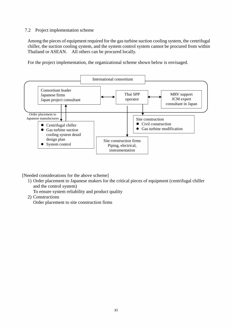
7.2 Project implementation scheme
Among the pieces of equipment required for the gas turbine suction cooling system, the centrifugal
chiller, the suction cooling system, and the system control system cannot be procured from within
Thailand or ASEAN. All others can be procured locally.
For the project implementation, the organizational scheme shown below is envisaged.
[Needed considerations for the above scheme]
1) Order placement to Japanese makers for the critical pieces of equipment (centrifugal chiller
and the control system)
To ensure system reliability and product quality
2) Constructions
Order placement to site construction firms
Consortium leader
Japanese firms
Japan project consultant
Thai SPP
operator
Centrifugal chiller
Gas turbine suction
cooling system detail
design plan
System control
International consortium
Site construction firms
Piping, electrical,
instrumentation
Order placement to
Japanese manufactures Site construction
Civil construction
Gas turbine modification
MRV support
JCM expert
consultant in Japan

1. Effectiveness of Gas Turbine Inlet Air Cooling System
Gas Turbine performance (power output and efficiency) will be improved by cooling the inlet air.
a. Gas Turbine Output by Ambient Temperature
Manufactures Power
Generation At 35℃
Power Generation
At 15℃
Output
G Company Gas Turbine (USA)
36.6MW
42MW
5.4MW
S Company Gas Turbine (Germany)
39MW
47MW
8MW
b. Gas Turbine Efficiency Improvement by Inlet Air Cooling
3.7% - 4% Heat Rate Improvement
2. CO2 Reduction by Inlet Air Cooling System application to Gas Turbine CO2 emission rate of power plant type is listed below. CO2 reduction will be done by increase the power generation by applying
Category Power
generation efficiency
CO2 emissions per unit
kg-CO2/kWh
Coal fired power generation
41% 0.864
Oil-fired power generation
41% 0.695
LNG-fired power generation
41% 0.476
SPP class gas turbine combined cycle power generation
52.7%
0.371
IPP class gas turbine combined cycle power generation
56.7%
0.344
CO2 Reduction By Applying Inlet Air Cooling System
To SPP Gas Turbine Combined Power Plant
Gas Turbine Heat Recovery Boiler
Steam
Centrifugal Chiller
G
CO2 Emission Factor of Power Plant

The average of CO2 emission factor of power grid in Thailand is 0.599kg-CO2/kWh and CO2 emission factor of Gas Turbine Combined Cycle power plant is 0.371kg-CO2/kWh. The CO2 reduction will be achieved by increasing of power generation of SPP Gas Turbine Combined Power Plant using Inlet Air Cooling System. Yearly CO2 emission reduction amounts are shown below table.
System
CO2 emission reduction
G Company GT x 2 + ST Combined Cycle Power Plant
39,922 ton-CO2/Year
S Company GT x 2 + ST Combined Cycle Power Plant
27,370ton-CO2/Year
Note : Above value is calculated based on the power plant is operated all year.
3. Gas Turbine Inlet Air Cooling System
Air Cooler
Air Cooler
Filter
Gas Turbine
Air Cooler
Air Cooler Installation Image
Gas Turbine
Cooling Tower
Chiller Module
Gas Turbine Inlet Air Cooling System Module Image
Centrifugal Chiller Centrifugal Chiller

- 1 -
Chapter 1 Background and Outline of the Survey
1.1 Survey background
(1) Survey purpose
At the 36th Intergovernmental Panel on Climate Change (IPCC) held in Stockholm, Sweden,
on September 26, 2013, the Summary for Policymakers from Working Group I’s Report (the
Physical Science Basis) for the IPCC’s Fifth Assessment Report was approved and published,
and it was announced that there was no room for doubt regarding the warming of climate
systems, and that human activities were extremely likely to be the major cause of the warming
observed from the middle of the 20th century. Japan is working to share among all countries
the goal of at least halving greenhouse gas emissions worldwide by 2050 while aiming for an
80% reduction in greenhouse gas emissions by 2050 as a long-term goal (based on the Basic
Environment Plan in the Cabinet decision of April 27, 2012). In order to halve greenhouse gas
emissions worldwide by 2050, greenhouse gas emission projects will need to be discovered and
formed on a large scale in the countries of the Asia-Pacific region, which are experiencing rapid
economic growth, and moves towards the construction of a sustainable, low-carbon society in
Asia accelerated. For that reason, the construction of a new mechanism, JCM (Joint Crediting
Mechanism) to appropriately assess Japan’s contributions to energy-generated CO2 emissions
reduction overseas.
A survey on the introduction of JCM large-scale energy-generated carbon dioxide reduction
technologies for a cogeneration plant and refrigeration plant at Thailand's Suvarnabhumi
International Airport was undertaken with the title of "FY2014 Consigned Survey of the
Introduction of Technologies to Reduce Carbon Dioxide Generated by JCM Large-scale Energy
to Achieve a Low-Carbon Society in Asia," aimed at surveying the introduction of technologies
and plants which would allow reductions on a large-scale of power-generated carbon dioxide in
power plants and energy-hungry industries as a survey to contribute to the commercialization
of future joint crediting mechanisms (JCM)
(2) Survey period
December 10, 2014 to Friday March 20, 2015

- 2 -
1.2 Work outline
Main goal of the current project assigned by the Ministry of the Environment: To conduct the
following survey with the aim of introducing technologies and plants that would allow the
reduction of energy-generated carbon dioxide on a large scale and would be used by power
plants and energy-hungry industries.
(1) Survey of the introduction of carbon dioxide-reduction technologies for SPP cogeneration
plants
Gas turbine combined-cycles are installed in industrial estates in Thailand as cogeneration
plants, and SPPs (Small Power Producers) that supply power, water, and heat, and to
industrial estates are showing large-scale business growth. The introduction of an inlet
cooling system in cogeneration plants used by existing SPPs and the amount of carbon
dioxide removed, the energy cost reductions, and the investment costs will be studied.
- 3 -
Chapter 2 Systems Related to Energy Supply in Thailand
2.1 SPPs, including international airports in Thailand
(1) About the SPP program
The government of Thailand established a program for small power producers(SPPs) called
“Regulations for the purchase of power from small power producers(SPPs) (For Electricity
Generated from Non-Conventional Energy, Waste, Residual Fuel and Co-generation)” in 1992
with the aim of working to reduce oil imports and increasing energy efficiency through the use
of renewable energy or waste heat from power generation, and has been expanding this system
to ensure the effective use of energy.
This system grants approval as SPP businesses to businesses that meet specific criteria and
have applied to EGAT for this project. Prices and other power sales conditions are presented by
EGAT and applied equally to all approved businesses, so this is different to competitive bidding.
When an SPP business is permitted to join this program, EGAT guarantees to buy up to 90
MW of electricity, and the remainder, as well as the heat (steam, cooling water) can be sold
independently to client companies in the industrial estates. The results of the survey of
companies selling generated power using this system are shown in Chapter 3.
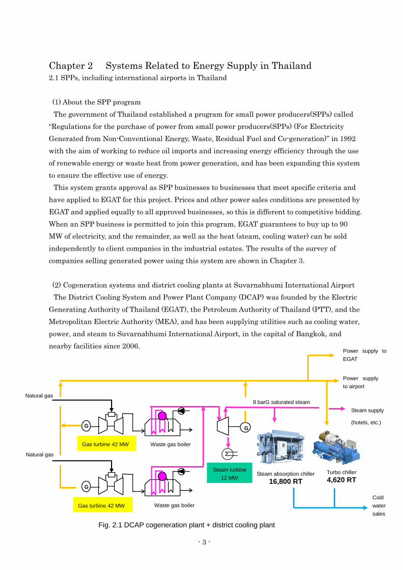
(2) Cogeneration systems and district cooling plants at Suvarnabhumi International Airport
The District Cooling System and Power Plant Company (DCAP) was founded by the Electric
Generating Authority of Thailand (EGAT), the Petroleum Authority of Thailand (PTT), and the
Metropolitan Electric Authority (MEA), and has been supplying utilities such as cooling water,
power, and steam to Suvarnabhumi International Airport, in the capital of Bangkok, and
nearby facilities since 2006.
G G
Gas turbine 42 MW
Waste gas boiler
Power supply
to airport
G
Natural gas
Waste gas boiler
Natural gas 8 barG saturated steam
Gas turbine 42 MW
Steam turbine
12 MW Steam absorption chiller
16,800 RT
Turbo chiller 4,620 RT
Power supply to
EGAT
Cold
water
sales
Steam supply
(hotels, etc.)
Fig. 2.1 DCAP cogeneration plant + district cooling plant
- 4 -
DCAP generates power from gas turbines using this system, creating steam by using their
hot waste heat, which generates more electricity from steam turbines, and also generates cold
water from the excess steam using an inlet refrigeration system. This power is sold to EGAT
and Suvarnabhumi International Airport (BKK), and the company is classified as an SPP. The
cogeneration system at BKK has also registered in the SPP program and signed a contract to
sell 50 MW of power to EGAT (a five-year contract that as of 2015 is still current). The contract
category is “SPP Non-Firm contract cogeneration system that was started commercial with
EGAT.”
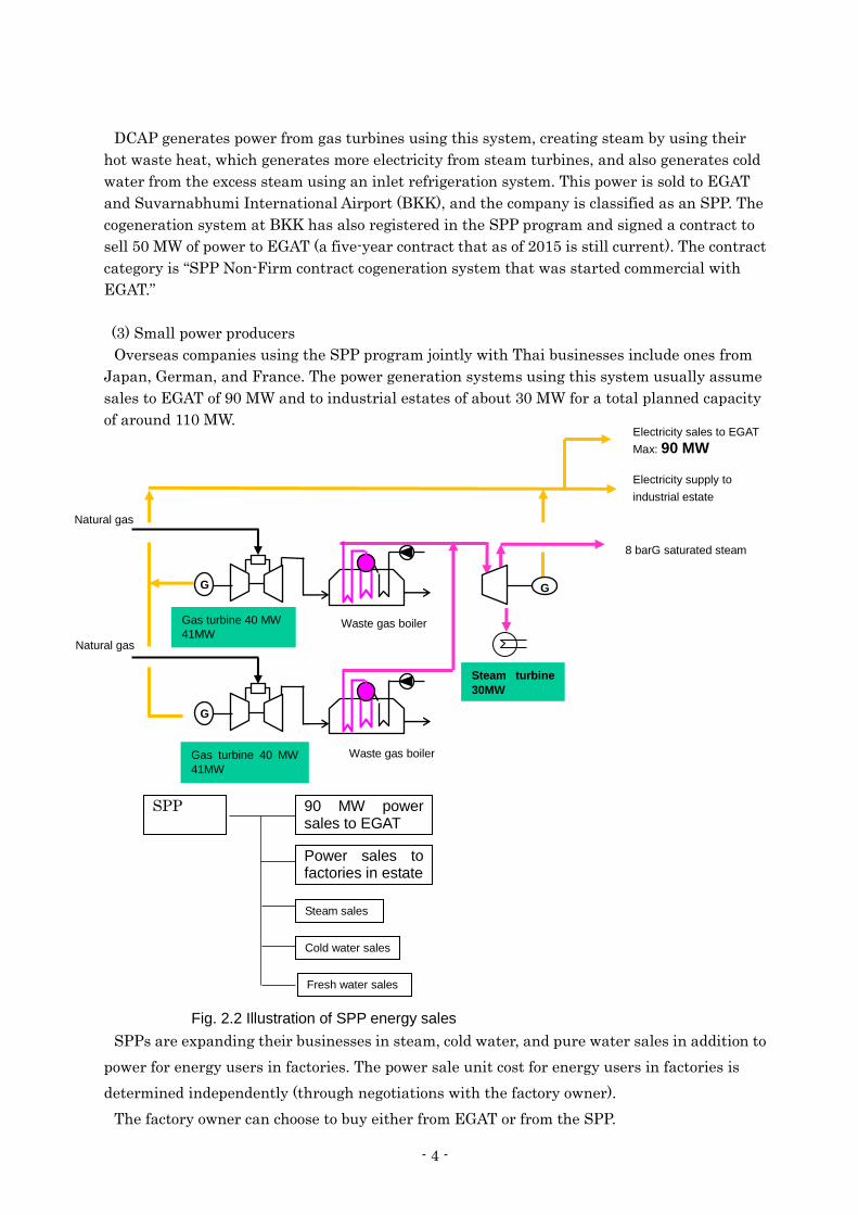
(3) Small power producers
Overseas companies using the SPP program jointly with Thai businesses include ones from
Japan, German, and France. The power generation systems using this system usually assume
sales to EGAT of 90 MW and to industrial estates of about 30 MW for a total planned capacity
of around 110 MW.
SPPs are expanding their businesses in steam, cold water, and pure water sales in addition to
power for energy users in factories. The power sale unit cost for energy users in factories is
determined independently (through negotiations with the factory owner).
The factory owner can choose to buy either from EGAT or from the SPP.
Fig. 2.2 Illustration of SPP energy sales
Gas turbine 40 MW
41MW
Waste gas boiler
Electricity supply to
industrial estate
Natural gas
Waste gas boiler
Natural gas
8 barG saturated steam
Gas turbine 40 MW
41MW
Steam turbine
30MW
Electricity sales to EGAT
Max: 90 MW
G G
G
SPP 90 MW power sales to EGAT
Power sales to factories in estate
Steam sales
Cold water sales
Fresh water sales

- 5 -
2.2 Power supply system
The power supply system in Thailand is as follows.
(1) Electric Generating Authority of Thailand (EGAT)
EGAT is a state-owned power generation and transmission company (under the jurisdiction
of the Ministry of Energy) that was established by the merger in May 1969 of three state
enterprises, namely the Yanhee Electricity Authority (YEA), the Lignite Authority (LA), and
the North-East Electricity Authority (NEEA). It enjoyed a monopoly on power generation and
transmission in Thailand for many years after that, but with the liberalization of electricity
businesses (discussed later), in 1992 independent power producers (IPPs) and small power
producers (SPPs) entered the field of power generation, so EGAT has played the role of the
off-taker (power purchaser) from that time. As of the end of 2011, EGAT owned and operated
51.3% (14,998 MW) of the power generation capacity of power companies overall (not including
home-generated). In addition, it buys electricity from IPPs, SPPs, and neighboring countries,
supplying this wholesale to the distribution companies (MEA and PEA), as well as directly
supplying it to major energy users. Moreover, it owns the power transmission equipment and
supply equipment, and operates the main power grid.
(2) Metropolitan Electricity Authority (MEA)
MEA was founded in 1958, before EGAT, from the Bangkok Power Company and the
government Bureau of Electricity Generation, and is under the jurisdiction of the Ministry of
Interior. As of 2012, it supplies power to the capital, Bangkok, and two neighboring provinces.
Source: The Future of Thai Power Generation and Commercial Opportunities for Japanese Companies 1)
Fig 2.3 Power supply system in Thailand
VSPP SPP IPP EGAT PEA DEDE Imports
EGAT
PEA MEA
User User Direct-supply user User
ERC Price regulations
Price regulations Power generation
Power transmission
Power generation
Organizational chart of power businesses in Thailand

- 6 -
(3) Provincial Electricity Authority (PEA)
PEA was founded in 1960 with the aim of promoting electrification in rural areas, and is
under the jurisdiction of the Ministry of Interior. It provides power to those regions not covered
by the MEA (73 provinces) in four separate groups, and its operational areas cover 99% of the
area of Thailand.
(4) Independent power producers (IPP)
In Thailand, it has been possible for the private sector to invest in power generation starting
in 1992. After Electricity Generating Public Co., Ltd (EGCO) was established by being
separated and made independent from EGAT, IPP recruitment (initial) started in 1994.
Recruitment was divided into Phase I (operations starting from 1996 to 2000, three sites with a
total output of 1,75o MW) and Phase II (operations starting from 2001, four sites with a total
output of 計4,927.5 MW), and seven projects were selected. Next, the second round of
recruitment was carried out in December 2007, for operations starting between 2012 and 2014,
with an extra 4 projects, for a total of 4,400 MW, selected. Then, on December 4, 2012,
recruitment started for the third batch, for operations starting from 2021 to 2026, and it has
been clarified that in July 2013 5,000 MW worth of enterprises were in the final list. IPPs are
broadly divided into those split off from EGAT such as EGCO and Ratchaburi Electricity
Generating Holding (RATCH), and others.
(5) Small power producers (SPP)
SPPs are power producing companies that sell between 10 and 90 MW of power to EGAT.
The system was introduced in 1992 in order to increase energy use efficiency and also help
reduce the importation and use of foreign oil by using cogeneration systems that use existing
fuels such as natural gas and coal, as well as renewable energy such as rubbish, biomass,
photovoltaics, and solar heat. As of March 2012, the total amount of power sold from SPPs to
EGAT was 2,554 MW. Note that Chubu Electric Power, Kansai Electric Power, and other
Japanese companies are also involved in power generation.
(6) Very small power producers (VSPP)
VSPPs are extremely small-scale power producers that sell less than 10 MW of power to
MEA or PEA. They encourage the development of renewable energy. As of March 2012, the
total amount of power sold from VSPPs was 682 MW.
(7) Energy Regulatory Commission (ERC)
The highest decision-making authority for energy policy overall, under the direct jurisdiction
of Office of the Prime Minister.

- 7 -
2.3 Participation of Japanese and overseas businesses in the SPP program
SPPs that have been approved by the Thai government are given guarantees that EGAT will
buy their electricity for the long term, between 20 and 25 years. Most SPPs use natural gas as
a fuel, but any increases in the cost of natural gas are reflected in the purchase price. Therefore
they are a low-risk, profit-guaranteed business, so companies from outside Thailand are also
investing in this business.
Japanese and European companies are investing, but businesses that are a merger with Thai
companies are being promoted.
Project holding company Investment in TAC Energy Co.
(47.6%)
Fig. 2.4 Power supply system in Thailand
Businesses in
SPP project
Japanese
companies
J Power Gulf JP
Seven 100 MW-class plants for a total capacity of 790 MW
J Power investment ratio: 90% for six sites
67.5% for one site
KEPCO Thailand Rojana Thermal
PP
Investment ratio: 39%, Plant output: 448,000 kW
Chubu
Electric
Power
Lad Krabang Industrial Estate (Approx. 30 km east of
Bangkok) Bangpoo Industrial Estate: two
sites
(Approx. 30 km south-east of
Bangkok)
Mitsui &
Co., Ltd. Joint promotion of 12
cogeneration projects with GED.
Gas cogeneration
power plant1,470 MW
(120 MW x nine generators, 130
MW x three generators)
Investment: Approx. 280 billion
yen
GED (70%), Mitsui & Co. (30%)
European
companies B.Grimm Power Limited
Sumitomo Corporation: 30% investment
Amata-EGCO Power Limited (165 MW, 70% equity interest) Amata-Power (Bangpakong)(167 MW、70% Equity interest)
Glow
A German conglomerate with 130 years of history in Thailand. Entered the power business in 1995.
French company
GDF SUEZ
Holds 69.11%
Generation capacity:
3,182 MW
Steam supply: 1,206 t/h
Cold water supply: 3,400
RT
(1) IPP combined
cycle power plant
Hemaraj Chonburi
Industrial Estate
Chonburi
(2) Coal-fired
GHECO-One 660 MW
(2) SPP power generation
a. Map Ta Phut Industrial Estate
Supplies power, steam, pure water, and
cold water
b Siam Eastern Industrial Park (Pluak
Daeng) 11 industrial estates
Power: 1,656 MW, steam: 1206 t/h
Cold water supply: 3,400 RT
Thai company Global Power Synergy Company
Limited (GPSP)
Joint venture company with PTT
SPP+ Cogeneration 701 MW
IPP

- 8 -
2.4 Industrial estates where SPPs supply power
The Industrial Estate Authority of Thailand (IEAT) develops and operates industrial estates
for the purpose of developing industry through the development and operation of industrial
estates throughout Thailand. In addition to industrial-use land, IEAT-operated industrial
estates also have infrastructure such as roads, sewers, waste processing facilities, flood
protection systems, and utilities such as electricity, water, and phones.
The IEAT owns 47 industrial estates throughout 15 provinces in Thailand. It directly runs 11
of these, while the remaining 36 are operating through joint ventures with the private sector.
Japan holds a 41.4% share of the investment accepted from overseas starting in 2009, the
largest single share.
Fig.2.5 Location of industrial estates near Bangkok

- 9 -
2.5 Power generation ratio and direction of Thai power generation
The estimated population of Thailand as of 2007 was 64 million, and the primary energy
supply volume for 2006 was approx. 100 million tons of oil equivalent (TOE), giving the country
an energy self-sufficiency rate of 52%. The total energy supplied in 2006 was 139 billion kWh,
of which 48.9% was generated and supplied by EGAT.
In addition, 70% of the fuel for current thermal power generation in Thailand is natural gas,
and 20% is coal. On March 14, 2013, EGAT announced that as around 70% of the 32,000,000
kW of power generation gas thermal power it held was gas-fired, and so there was the risk of
power shortages if the gas supply from Myanmar was stopped, it would review its current
Power Development Plan (PDP: 2013-2013: Develop 39,000,000 kW by 2030) and increase the
ratio of coal-fired power plants in the future. Development in the current PDP is focused on
combined cycle power plants, and development of coal-fired plants remains at 8,000,000 kW.
The new PDP, which is scheduled for announcement in October, is expected to include the
development of coal-fired plants to at least 20,000,000 kW. The increase is expected to be based
around coal-fired power generation.
Cases of planning delays due to the opposition of local residents and studies on the
construction of IPPs with a view towards improving the power situation have also been
reported. The speed of development of combined cycle power facilities using gas turbines is
slowing, and with the increase in the ratio of coal-fired power plants, it is thought that the CO2
emissions per unit for power in Thailand will worsen. As the construction of power plants shifts
from gas-fired to coal-fired, the introduction of technologies to improve the efficiency and boost
the output of the existing high-efficiency gas turbine combined cycle power plants is important.
2.6 Gas supply for power generation
70% of power generation relies on natural gas, which is imported from Myanmar and
supplied from gas fields being co-developed with Malaysia. Gas supply for natural gas-fired
power plants in Thailand relies on gas supplied from Myanmar as well. With 2013 as a base,
the amount of natural gas produced in Myanmar was 13.1 billion m3, of which 70% was
supplied to Thailand.
(1) Natural gas supply within Thailand
Thai pipelines are divided into two, with the marine trunk line transporting gas overland
from the gas fields in the Gulf of Thailand and the Myanmar pipeline importing gas from
Myanmar. The completion at the end of 2000 of the pipeline between Wangnoi and the
Ratchaburi power plant where Myanmar gas is used to generate power has allowed the
development of an east-west pipeline network centered in Bangkok. This has also allowed
natural gas from the Gulf of Thailand to be supplied to the Ratchaburi power plant, as well as
transportation the other way.

- 10 -
(2) Gas supply from Myanmar
1) Yetagun gas field
Discovered in 1992 by ChevronTexaco, production started in 2000. A contract to supply gas
for 30 years was signed, and gas is exported to Thailand along a 230 km underwater and a 42
km overland pipeline.
2) Zawtika gas field
A contract to sell 240,000,000 cf of natural gas per day was signed with Thailand in July
2010, and supply started in August 2914 using a 270 km underwater and 30 km overland
pipeline. PTT Exploration and Production Public Company Limited (PTTEP) owns 80% of the
interests, with MOGE owning 20%. This the largest foreign gas field development for PTTEP.
2.7 Considerations regarding the direction of natural gas usage in Thailand
The Power Development Plan (PDP: 2013-2030: Develop 39,000,000 kW by 2030) announced
in December 2014 contained revisions for increasing the amount of coal-fired power plants,
which is expected to increase the CO2 emissions per unit for power in Thailand.
(1) Natural gas export production trends in Thailand and changes to coal-fired power
production
Thailand’s energy supply is mainly reliant on domestic natural gas. However, gas production
and imports of gas from neighboring countries will peak in the latter half of the 2010s and then
gradually decrease, with LNG imports planned, which will happen in 2011 and 2012
respectively.
Natural gas pipelines within Thailand
Source: Wide-area ASEAN Natural Gas Pipeline
Network Concepts4)
Natural gas pipelines from Myanmar
Source: JPEC Report5)
Gas pipeline
Fuel oil pipeline
Oil field
Refinery
To Kunming
China
Myanmar
Thailand
(From “East & West Report”)

- 11 -
(2) Issues for the stable supply of natural gas
In both April and December, 2013, gas supply from Myanmar was stopped for a week, and in
June 2014, supply from the joint fields in the Gulf of Thailand was stopped, forcing a 10% cut
in power consumption among factories in southern Thailand. Development of gas fields in the
Gulf of Thailand has also seen no new concessions for the last seven or so years. The costs of
natural gas in Thailand are kept lower than the prevailing cost-based market rate through
subsidies.

- 12 -
2.8 Current issues regarding SPPs in Thailand
The SPP project contracts that started from the program created in 1992 will start to expire
from 2017. SPPs normally sign contracts with government organizations to supply electricity
for 25 years, and supply electricity as well as heat and steam to commercial factories in
industrial estates from power plants built in these estates. Power plants in 25 older industrial
estates, including Amata Nakorn in Chonburi province and Map Ta Phut and Laem Chabang
in Rayong province will see their contracts expire in 2017 as part of the first wave. These 25
power plants produce a total of 2,908 MW, of which the contracted supply amount is 1,800 MW.
After the contracts between the SPPs and the government expires, power supply will be
assured through re-bidding for concessions or the signing of new contracts or replacement
contacts with existing businesses, but the recent political upheavals have meant that the
government has not determined its policy. There are 28 businesses in Thailand that will see
their contracts expire in the next decade. In addition to 25 SPPs, this number also includes
three IPPs (contracted to supply 2,250 MW of power) whose contracts will expire.

- 13 -
References
1) Asia Pacific Institute of Research materials 14-05: “Development of the Power Market in
SE Asia” and Japanese Corporate Research Society Report, “The Future of Thai Power
Generation and Commercial Opportunities for Japanese Companies” (FY2013)
2) The Japan Machinery Federation: FY2010 Japan Consulting Institute Survey Research
Report on the Construction and Introduction of Plant Maintenance Infrastructure to
Developing Nations to Contribute to the International Development of Power Plants in
Japan.
3) Makiko Ono: “Meaning and Issues for Initiatives to EPC by Power Generation System
Manufacturers: Strategic directions in thermal power plant markets in newly-emerging
nations,” Mizuho Industry Focus, Vol. 158, July 18, 2014
4) Toru Hasegawa, “Wide-area ASEAN Natural Gas Pipeline Network Concepts: A
validation of their concepts, issues, and merits”
http://oilgas-info.jogmec.go.jp/pdf/0/392/200107_012a.pdf
5) JPEC Report, December 18, 2014: Myanmar’s Coal and Gas Industry as it Experiences
New Development Under Economic Liberation
6) JOGMEC Oil Research Department: Thailand and Malaysia: Overseas Expansion and
Selection of Power Generation Fuels Related to SOE Oil Companies
http://oilgas-info.jogmec.go.jp/pdf/4/4386/1105_out_m_my_th_invest.pdf
7) Ministry of Energy Summary of Thailand Power Development Plan 2012 - 2030 (PDP2010: REVISION 3)

- 14 -
Chapter 3 Applicable Carbon Dioxide Reduction Technologies for SPPs and Cogeneration Systems at Suvarnabhumi International Airport
This section will explain the technologies that can be applied to SPP power generation
systems (including the cogeneration system at Suvarnabhumi International Airport).
3.1 SPP businesses targeted for the field survey
A study was made of the effects on combined cycle power generation for cold water and
steam supply systems in SPP power plants that provide power, steam, and cold water as well
as inlet cooling systems for gas turbine combined cycle power generation systems run by IPP
and EGAT, and power plants operated under the SPP program, with the aim of creating a
survey that aims for the introduction of technologies, plants, etc. which can allow the
reduction of energy-based carbon dioxide on a large scale and be used in power plants and
major energy-consuming industries.
(1) Survey of power plants in the SPP program
The SPP power plant owners below were requested to cooperate with the survey through
interviews.
First Survey January 7 – 9, 2015
SPP owner interview and field survey cooperation requests
a. SPP company with investment from Japan (G Co.)
b. SPP company with investment from Europe (G. Co.)
c. SPP company with investment from Europe (B. Co.)
d. Domestic Thai SPP company (G. Co.)
Second survey January 26 – 28, 2015
SPP owner interview and field survey cooperation requests
a. Domestic Thai SPP company (G. Co.)
b. Domestic Thai SPP company (D. Co.)
An outline of these clients is shown in “2.3 Participation of Japanese and overseas businesses
in the SPP program.” Interviews were conducted with each SPP owner, and the data for the
power generation capacity and gas turbine manufacturer model for each industrial estate are
shown in Table 3.1.
As shown in Table 3.1, gas turbines used in SPP companies are divided into two types: the
German Siemens SGT-800 gas turbine and the US General Electric LM6000.
In addition, Table 3.2 shows the lists of businesses that are registered as SPPs.
Table 3.2 classifies SPPs into “Firm Contract” and Non-Firm Contract.”

- 15 -
Capacity EGAT Steam
Major Investors Company Name/Location (MW) sales Supply
Saraburi A Cogeneration Co,.Ltd Siemens SGT-800 106.2
Saraburi B Cogeneration Co,.Ltd Siemens SGT-800 106.2
Industrial Cogen Co,. Ltd Siemens SGT-800 113.3
Gulf JP Combine Heat & Power Co., Ltd Siemens SGT-800 109.1
Chachoensao Cogeneration Co,Ltd Siemens SGT-800 107.8
Phatum Cogeneration Co,.Ltd Siemens SGT-800 118.9
R1L Cogenration Co,.Ltd Siemens SGT-800 124.1
Gulf Cogeneration Co,. Ltd General Electric GE(MS6001B) 111 90
Sumut Prakan Cogeneration Co, Ltd General Electric GE(MS6001B) 128 90
Nong Khae Cogeneration Co, Ltd General Electric GE(MS6001B) 131 90
Amata Steam Supply Co,.Ltd Siemens SGT-800 165.8
G Grim Amata Power Co,.Ltd Siemens SGT-800 108.7
Amata Power Co,.Ltd Siemens SGT-800 165.8
Amata B Grim Power 1 Limited Siemens V 64.3 168 90
Amata B Grim Power 2 Limited Alstom PG 6561B 108 90
Glow SPP1 Co,Ltd (1) Alstom GT8C 67.7 55
Glow SPP1 Co,Ltd (2) Alstom GT8C 68.3 55
Glow Energy Glow SPP2 Co,Ltd (1) General Electric GE(MS6001B) 70 60
Glow SPP2 Co,Ltd (2) General Electric GE(MS6001B) 120 90
Thai National Power Co,.Ltd IHI LM6000F 101.2
Rojana Power Rojana Power Co,Ltd IHI LM6000PD 106
Rojana Power Co,Ltd IHI LM6000PD 122 90
Sahacogen Power Plants Sahacogen (Chonburi) Public Company Limited. IHI LM6000PC x 3 170 50 t/h
PTT Banpa-in Ayutthaya 119 20t/h
Global Power Synergy Bangkadee Pathumthani 117 15t/h
Company Limited (GPSC) Nawanakorn Pathumthani 127 15t/h
CUP-1 (At Map Ta Phut, Rayong)
CUP-2 (At Map Ta Phut, Rayong)
CUP-3 (At Hemaraj IE, Rayong)ROJANA POWER COMPANY LTD Rojana Industrial Park at Ayyuthaya General Electric LM 6000 PCx 6 344 MWe
EGCO Cogeneration Co., Ltd Rayong, Thailand General Electric LM 6000 PCx 2 120 10t/h
DCAP Suwannabumi International Air Port IHI LM 6000 PCx 2 55 50
Gas Turbine
[Firm Contract]
The companies have contracts that do guarantee the operation schedule of power plants and
the supplied power output with EGAT. Therefore the power plant outputs and operation are
bound by the EGAT contract. The contract period is long, 25 years.
Non-Firm Contract
The companies have contracts that do not guarantee the operation schedule of power plants
and the supplied power output with EGAT. These contracts do not bind power sales to EGAT in
particular. The contracts are for five years, and can be extended as needed. The Suvarnabhumi
International Airport (BKK) district cooling plant’s cogeneration equipment also use non-firm
contracts
Table 3.1 List of SPP combined power plants

- 16 -
Table 3.2.1 List of SPPs (SPP Firm Contract)
No. Company Location Power Plant Type Type of fuel Installed CapacityContract amount of
electric powerTerm of agreement SCOD COD
(MW) (MW)
1 Glow Energy Public Company Limited. (Phase 1) Mueang, Rayong Co-Generation Power Plant Natural Gas 150.000 90.000 21 1-Apr-1996 1-Apr-1996
2 Glow Energy Public Company Limited. (Phase 2) Mueang, Rayong Co-Generation Power Plant Natural Gas 150.000 90.000 21 1-Oct-1996 1-Oct-1996
3 PTT Petrochemical Public Company Limited Mueang, Rayong Thermal Power Plant Coal 55.000 9.500 21 1-Feb-1997 1-Feb-1997
4 PTT Global Chemical Public Company Limited Mueang, Rayong Co-Generation Power Plant Natural Gas, Off Gas 171.100 32.000 21 1-Apr-1997 1-Apr-1997
5 Glow SPP 1 Co.,Ltd. (Phase 1) Mueang, Rayong Co-Generation Power Plant Natural Gas 67.680 55.000 23 15-Jan-1998 3-Feb-19986 Thaioil Power Co.,Ltd. Sriracha, Chonburi Co-Generation Power Plant Natural Gas 138.880 41.000 25 1-Mar-1998 1-Apr-19987 Defence Energy Department Phang, Chiangmai Biodiesel Fuel Oil 10.400 4.500 21 1-May-1998 26-Jun-19988 Gulf Cogeneration Co.,Ltd. Mueang, Saraburi Co-Generation Power Plant Natural Gas 111.000 90.000 21 14-Aug-1998 3-Sep-19989 Amata B.Grimm Power 1 Co.,Ltd. Mueang, Chonburi Co-Generation Power Plant Natural Gas 168.000 90.000 21 30-Sep-1998 17-Sep-199810 Glow SPP 1 Co.,Ltd. (Phase 2) Mueang, Rayong Co-Generation Power Plant Natural Gas 66.345 55.000 23 15-Aug-1998 18-Sep-199811 Bangkok Cogeneration Co.,Ltd. Mueang, Rayong Co-Generation Power Plant Natural Gas 115.300 90.000 21 25-Dec-1998 4-Feb-199912 National Power Supply Public Company Limited (Phase 1) Srimahapote, Prachinburi Thermal Power Plant Coal, Scraps of wood 164.000 90.000 25 15-Mar-1999 12-Mar-199913 Glow SPP 2 Co.,Ltd. (Phase 1) Mueang, Rayong Gas Turbine Power Plant Natural Gas 70.000 60.000 25 1-Apr-1999 29-Mar-199914 Sahacogen (Chonburi) Publib Company Limited Sriracha, Chonburi Co-Generation Power Plant Natural Gas 139.000 90.000 25 31-Mar-1999 19-Apr-199915 Glow SPP 2 Co.,Ltd. (Phase 2) Mueang, Rayong Gas Turbine Power Plant Natural Gas 70.000 60.000 25 1-May-1999 26-Apr-199916 Rojana Power Co.,Ltd. (Phase 1) U-Thai, Ayutthaya Co-Generation Power Plant Natural Gas 131.500 90.000 25 31-Mar-1999 26-May-199917 National Power Supply Public Company Limited (Phase 2) Srimahapote, Prachinburi Thermal Power Plant Coal, Scraps of wood 164.000 90.000 25 1-Jul-1999 12-Jul-199918 Samutprakarn cogeneration co. ltd Mueang, Samutprakarn Co-Generation Power Plant Coal 128.000 90.000 21 1-Jul-1999 23-Aug-199919 Glow SPP 3 Co.,Ltd. (Phase 1) Srimahapote, Prachinburi Thermal Power Plant Coal 160.000 90.000 25 1-Jun-1999 1-Sep-199920 Glow SPP 3 Co.,Ltd. (Phase 2) Srimahapote, Prachinburi Thermal Power Plant Natural Gas 160.000 90.000 25 15-Aug-1999 20-Mar-200021 Glow SPP 11 Co.,Ltd. (Phase 1) Pluagdeang, Rayong Co-Generation Power Plant Natural Gas 120.000 90.000 25 30-Sep-2000 4-Oct-200022 Nong khae cogeneration co. ltd Nongkhae, Saraburi Co-Generation Power Plant Natural Gas 131.000 90.000 21 1-Oct-2000 12-Oct-200023 Sime darby power co. ltd Sriracha, Chonburi Co-Generation Power Plant Natural Gas 105.000 60.000 21 15-Jul-2001 16-Jul-200124 Amata B.Grimm Power 2 Co.,Ltd. Mueang, Chonburi Co-Generation Power Plant Natural Gas 108.000 90.000 21 30-Sep-2001 28-Sep-200125 Egco cogeneration co. ltd Bankai, Rayong Co-Generation Power Plant Natural Gas 120.000 60.000 21 1-Jan-2003 28-Jan-200326 Siam Power Generation Public Company Limited. (Phase 1) Bankai, Rayong Co-Generation Power Plant Natural Gas 168.430 90.000 21 30-Oct-2010 29-Dec-201027 Glow Energy Public Company Limited. (Phase 3) MapTaPut Industrial Estate Co-Generation Power Plant Natural Gas 77.000 74.000 25 1-Jun-2012 1-Jun-201228 Amata B.Grimm Power 3 Co.,Ltd. Amatanakorn Industrial Estate Co-Generation Power Plant Natural Gas 165.820 90.000 25 1-Sep-2012 1-Oct-201229 Glow SPP 11 Co.,Ltd. (Phase 2) Pluagdeang, Rayong Co-Generation Power Plant Natural Gas 101.180 90.000 25 1-Dec-2012 12-Dec-201230 Gulf JP KP1 Co., Ltd. Nongkhae, Saraburi Co-Generation Power Plant Natural Gas 106.200 90.000 25 5-Jan-2013 5-Jan-201331 Gulf JP KP2 Co., Ltd. Nongkhae, Saraburi Co-Generation Power Plant Natural Gas 113.300 90.000 25 1-Feb-2013 1-Feb-201332 Gulf JP TCL Co., Ltd. Mueang, Saraburi Co-Generation Power Plant Natural Gas 106.200 90.000 25 1-Mar-2013 1-Mar-201333 Gulf JP NNK Co., Ltd. Mueang, Chachengsao Co-Generation Power Plant Natural Gas 107.790 90.000 25 1-Apr-2013 1-Apr-201334 Gulf JP NLL Co., Ltd. Bankai, Rayong Co-Generation Power Plant Natural Gas 124.130 90.000 25 1-May-2013 1-May-201335 Amata B.Grimm Power (Rayong) 2 Co.,Ltd. Pluagdeang, Rayong Co-Generation Power Plant Natural Gas 108.740 90.000 25 1-Jun-2013 21-Jun-201336 Bangpa-in Cogeneration Co.,Ltd. Bangpa-in Industrial Estate Co-Generation Power Plant Natural Gas 106.250 90.000 25 1-Jun-2013 28-Jun-201337 Gulf JP CRN Co., Ltd. Samkhok, Patumthani Co-Generation Power Plant Natural Gas 118.890 90.000 25 1-Jul-2013 1-Jul-201338 Gulf JP NK2 Co., Ltd. Nongkhae, Saraburi Co-Generation Power Plant Natural Gas 109.100 90.000 25 1-Oct-2013 1-Oct-201339 Rojana Power Co.,Ltd. (Phase 2) U-Thai, Ayutthaya Co-Generation Power Plant Natural Gas 131.460 90.000 25 1-Jul-2013 18-Oct-201340 Navanakorn Electric Co.,Ltd. Klongluang, Patumthani Co-Generation Power Plant Natural Gas 118.500 90.000 25 2-Apr-2013 31-Oct-201341 Amata B.Grimm Power (Rayong) 1 Co.,Ltd. Pluagdeang, Rayong Co-Generation Power Plant Natural Gas 165.820 90.000 25 1-Nov-2013 1-Nov-2013
Total Capacity 4,903.015 3,211.000 MW
SPP Firm contract cogeneration system that were started commercial with EGAT

- 17 -
Table 3.2.2 List of SPPs (SPP Firm Contract) (using renewable energy)
Table 3.2.3 List of SPPs (SPP Firm Contract) (contracted but have not started operation)
No. Company Location Power Plant Type Type of fuel Installed CapacityContract amount of
electric powerTerm of agreement SCOD COD
(MW) (MW)42 National Power Plant 3 Co.,Ltd. Panomsarakham, Chachengsao Thermal Power Plant Husk, Scraps of wood 47.400 41.000 25 1-Apr-1999 21-Apr-199943 National Power Plant 2 Co.,Ltd. Bangpakong, Chachengsao Thermal Power Plant Husk, Scraps of wood 10.400 8.000 21 1-Apr-1999 7-May-199944 Bio-Mass Power Co.,Ltd. Watsing, Chainat Thermal Power Plant Bagasses 6.000 5.000 25 31-Jan-2001 9-Sep-200145 Roi-et green co.,ltd. Mueang, Roi-et Thermal Power Plant Bagasses 9.900 8.800 21 1-Apr-2003 29-May-200346 National Power Plant 5 Co.,Ltd. Srimahapote, Prachinburi Thermal Power Plant Scraps of wood & Black Liquor 87.200 50.000 25 31-Oct-2003 5-Nov-200347 National Power Plant 11 Co.,Ltd. Srimahapote, Prachinburi Thermal Power Plant Black Liquor 32.900 25.000 25 28-Nov-2003 2-Dec-200348 Can chang bio-energy co.,ltd. Danchang, Suphanburi Thermal Power Plant Bark, Husk, Bagasse 48.000 25.000 21 16-May-2004 15-Jul-2004
The company requested to increase production 2.000 1-Jul-200549 Mitr phol bio power co.,ltd. (Mitr Phol Sugar Group) Phukhiao, Chiayaphum Thermal Power Plant Bark, Husk, Bagasse 56.900 29.000 21 16-Jul-2004 6-Sep-200550 A.T. biopower co.,ltd. Bangmunnak, PhiChit Thermal Power Plant Husk 22.500 20.000 25 24-Dec-2005 21-Dec-200551 SATUK BIOMASS CO., LTD Satuek, Buriram Thermal Power Plant Husk and Other Biomass 7.500 6.500 21 15-Dec-2005 24-Jan-200652 Gulf yala green co.,ltd. Mueang, Yala Thermal Power Plant Rubber wood chips 23.000 20.200 25 1-Oct-2006 28-Nov-200653 Khon Kaen Sugar Power Plant Co.,Ltd. (Phase 1) Nampong, Khonkhan Thermal Power Plant Bagasses and Other Biomass 30.000 20.000 21 31-Oct-2006 26-Dec-200654 Mungcharoen green power co. ltd Mueang, Surin Thermal Power Plant Husk 9.900 8.000 21 15-Dec-2006 23-Jan-200755 Surat thani green energy co. ltd Punpin, Suratthani Thermal Power Plant Palm 9.900 8.800 25 1-Jul-2007 13-Sep-200756 Dan chang bio-energy co. ltd (Phase 2) Danchang, Suphanburi Thermal Power Plant Bagasse 11.400 10.000 25 15-Sep-2009 13-Nov-2009
The company requested to increase production 0.800 1-Sep-2012 1-Sep-201257 Mitr phol biopower co. ltd (Phase 2) Phukhiao, Chiayaphum Thermal Power Plant Bagasse 11.400 10.000 25 15-Sep-2009 13-Nov-200958 Mungcharoen biomass co. ltd Mueang, Surin Thermal Power Plant Bagasse and Scraps of wood 17.000 15.500 25 1-Jul-2012 5-Sep-2012
Total Capacity 441.300 313.600 MW
No. Company Location Power Plant Type Type of fuel Installed CapacityContract amount of
electric powerTerm of agreement SCOD COD
(MW) (MW)
59 B.grimm bip power co. ltd Mueang, Patumthani Co-Generation Power Plant Natural Gas 112.000 90.000 25 1-Mar-201560 Siam Power Generation Public Company Limited (Phase 2) Bankai, Rayong Co-Generation Power Plant Natural Gas 166.530 90.000 25 1-Jun-2016
Total Capacity 278.530 180.000 MW
61 Ratchaburi world cogeneration co. ltd Ratchaburi Industrial Estate Co-Generation Power Plant Natural Gas 115.280 90.000 25 1-Nov-201462 Advance agro asia co. ltd Panomsarakham, Chachengsao Co-Generation Power Plant Natural Gas 105.430 90.000 25 1-Mar-201563 PPTC Co.,Ltd. Latkrabang Industrial Estate Co-Generation Power Plant Natural Gas 113.900 90.000 25 1-Dec-201564 Siam pure rice co. ltd Chaiyo, Angthong Co-Generation Power Plant Natural Gas 105.506 90.000 25 1-Jun-2018
Total Capacity 440.116 360.000 MW
65 Ratchaburi world cogeneration co. ltd (Phase 2) Ratchaburi Industrial Estate Co-Generation Power Plant Natural Gas 115.280 90.000 25 1-Mar-201566 Bangkadi Clean Energy Ltd Bangkadi Industrial Park Co-Generation Power Plant Natural Gas 113.290 90.000 25 1-Jul-201567 SSUT Co.,Ltd. Bangpu Industrial Estate Co-Generation Power Plant Natural Gas 108.300 90.000 25 1-Apr-2016
68 Bowin Clean Energy Co., LtdHemmarat Industrial Estate Chonburi
Co-Generation Power Plant Natural Gas 113.902 90.000 25 1-Nov-2016
69 IRPC Clean power co. ltd (Phase 1) Mueang, Rayong Co-Generation Power Plant Natural Gas 115.217 90.000 25 1-Jun-201770 IRPC Clean power co. ltd (Phase 2) Mueang, Rayong Co-Generation Power Plant Natural Gas 115.217 90.000 25 1-Jun-2017
Total Capacity 681.206 540.000 MW
SPP Firm contract cogeneration system according to the conclusion of the National Energy Policy Council 2007 that were sign the contract but still not start commercial with EGAT.
SPP Firm contract cogeneration system according to the conclusion of the National Energy Policy Council 2010 that were sign the commercial contract after EIA but still not start commenrcial with EGAT.
SPP Firm contract cogeneration system according to the conclusion of the National Energy Policy Council 2010 that were sign the commercial contract before EIA and the contract has been effective but still not start commenrcial with EGAT.

- 18 -
No. Company Location Power Plant Type Type of fuel Installed CapacityContract amount of
electric powerTerm of agreement SCOD COD
(MW) (MW)
71 Amata B.Grimm Power 4 Co.,Ltd. Amatanakorn Industrial Estate Co-Generation Power Plant Natural Gas 113.902 90.000 25 1-Nov-201572 Thai Oil Public Company Limited (Phase 1) Sriracha, Chonburi Co-Generation Power Plant Natural Gas 121.730 90.000 25 1-Apr-201673 Amata B.Grimm Power 5 Co.,Ltd. Amatanakorn Industrial Estate Co-Generation Power Plant Natural Gas 113.902 90.000 25 1-Jun-201674 Nava Nakorn Electricity Generating Co., Ltd. Klongluank, Patumthani Co-Generation Power Plant Natural Gas 129.320 90.000 25 1-Jun-201675 Thai Oil Public Company Limited (Phase 2) Sriracha, Chonburi Co-Generation Power Plant Natural Gas 109.740 90.000 25 1-Jun-201676 SSUT Co.,Ltd (Phase 2) Bangpu Industrial Estate Co-Generation Power Plant Natural Gas 108.300 90.000 25 1-Jun-201677 Nava Nakorn Electricity Generating Co., Ltd. (Phase 2) Banpong, Ratchaburi Co-Generation Power Plant Natural Gas 124.640 90.000 25 1-Feb-201778 Nava Nakorn Electricity Generating Co., Ltd. (Phase 3) Banpong, Ratchaburi Co-Generation Power Plant Natural Gas 124.640 90.000 25 1-Feb-2017
79 Rainbow Power Co.,Ltd.Eastern Seaboard Industrial Estate, Rayong
Co-Generation Power Plant Natural Gas 124.957 90.000 251-May-2017
80 Amata B.Grimm Power (Rayong) 3 Co.,Ltd. Amatacity Industrial Estate Co-Generation Power Plant Natural Gas 113.902 90.000 25 1-Jun-201781 Bangpa-in cogeneration co. ltd (Phase 3) Bangpa-in Industrial Estate Co-Generation Power Plant Natural Gas 120.500 90.000 25 1-Jun-201782 Rojana Power Co.,Ltd. (Phase 3) Rojana Industrial Park Co-Generation Power Plant Natural Gas 112.010 90.000 25 1-Jun-201783 The Electricity Generating Public Company Limited (Phase 1) Klongluang, Patumthani Co-Generation Power Plant Natural Gas 125.490 90.000 25 1-Jun-2017
84 Electric and Steam Co.,Ltd.Eastern Seaboard Industrial Estate, Rayong
Co-Generation Power Plant Natural Gas 123.499 90.000 25 1-Jul-2017
85 Eastern Seaboard Power Co.,Ltd.Eastern Seaboard Industrial Estate, Rayong
Co-Generation Power Plant Natural Gas 123.499 90.000 25 1-Sep-2017
86 Rayong Electricity Generating Co., Ltd.Hemmarat Eastern Seaboard Industrial Estate, Rayong
Co-Generation Power Plant Natural Gas 123.499 90.000 25 1-Nov-2017
87 2010 Cogeneration Co.,Ltd.Hemmarat Eastern Seaboard Industrial Estate, Rayong
Co-Generation Power Plant Natural Gas 123.499 90.000 251-Jan-2018
88 Kabin Cogen Co., Ltd Kabinburi, Prachinburi Co-Generation Power Plant Natural Gas 119.643 90.000 25 1-Mar-201889 Amata B.Grim Power (Rayong) 4 Co.,Ltd. Amatacity Industrial Estate Co-Generation Power Plant Natural Gas 113.902 90.000 25 1-Jun-201890 HITECH COGENERATION CO., LTD Hi-tech Industrial Estate Co-Generation Power Plant Natural Gas 124.684 90.000 25 1-Sep-201891 Amata B.Grim Power (Rayong) 5 Co.,Ltd. Amatacity Industrial Estate Co-Generation Power Plant Natural Gas 113.902 90.000 25 1-Oct-201892 Victory Energy Co.,Ltd. Hi-tech Industrial Estate Co-Generation Power Plant Natural Gas 124.957 90.000 25 1-Nov-2018
93 Palang ngan promburi Co.,Ltd. (บรษัิท พลังงานพรหมบรุี จ ากัด)Hemmarat Industrial Zones, Rayong
Co-Generation Power Plant Natural Gas 122.350 90.000 251-Jan-2019
94 Thai energy generator Co.,Ltd. Nongkhae, Saraburi Co-Generation Power Plant Natural Gas 119.643 90.000 25 1-Mar-2019
95 Suranaree Energy Generating Co., LtdSuranari Industrial Zones, Nakornratchasima
Co-Generation Power Plant Natural Gas 123.499 90.000 25 1-May-2019
96 B.Grim Power (Ratchaburi) 1 Co.,Ltd. V.R.M Industrial Estate, Ratchaburi Co-Generation Power Plant Natural Gas 113.902 90.000 25 1-Jun-201997 Ratchaburi cogeneration co. ltd Bangpong, Ratchaburi Co-Generation Power Plant Natural Gas 111.759 90.000 25 1-Jun-2019
98 Blue sky cogen co ltdSuranari Industrial Zones, Nakornratchasima
Co-Generation Power Plant Natural Gas 124.957 90.000 251-Jul-2019
99 B.Grim Power (Ratchaburi) 2 Co.,Ltd. V.R.M Industrial Estate, Ratchaburi Co-Generation Power Plant Natural Gas 113.902 90.000 25 1-Oct-2019
Total Capacity 3,464.129 2,610.000 MW
100 The Electricity Generating Kornburi Co.,Ltd. (KBS Group) Kornburi, Nakornratchasima Thermal Power Plant Bagasse 35.000 22.000 25 15-Dec-2013
Total Capacity 35.000 22.000 MW
Grand Total Capacity 10,243.296 7,236.600 MW
SPP Firm contract cogeneration system according to the conclusion of the National Energy Policy Council 2010 that were sign the commercial contract before EIA and the contract has not been effective and still not start commenrcial with EGAT.
SPP Firm contract renewable that is pending the signing of the contract.
SCOD : Scheduled Commercial Operation DateCOD : Commercial Operation DateEIA : Environmental Impact Assessment

- 19 -
Table 3.2.4 List of SPPs (SPP Non-Firm Contract)
No. Company Location Power Plant Type Type of fuel Installed CapacityContract amount of
electric powerTerm of agreement SCOD COD
(MW) (MW)
1 IRPC Public Company Limited (Phase 1) Mueang, Rayong Thermal Power Plant Natural Gas, Coal, Oil 108.000 45.000 5 Years and Continuing - 28-May-19942 Panjapol Puls Industries Public Company Limited Bangsai, Ayutthaya Thermal Power Plant Coal 40.000 8.000 5 Years and Continuing - 16-Nov-19953 DCAP Bangphli, Samutprakarn Gas Turbine Power Plant Natural Gas 55.000 50.000 5 Years and Continuing - 15-Mar-2006
The company requested to increase produciton 40.000 15.000 28-Jan-20134 Global Power Synergy Publib Company limited (Phase1) Mueang, Rayong Thermal Power Plant Natural Gas 300.000 60.000 5 Years and Continuing - 24-Jan-20095 Global Power Synergy Publib Company limited (Phase2) Mueang, Rayong Thermal Power Plant Natural Gas 150.000 40.000 5 Years and Continuing - 17-Sep-20106 RojanaPower Co.,Ltd. (Phase 4) Uthai, Ayutthaya Thermal Power Plant Natural Gas 121.135 50.000 5 Years and Continuing - 26-Jul-2013
The company requested to increase produciton 20.000 - 5-Jul-2014Total Capacity 814.135 288.000 MW
7 PPT Global Chemical Ltd. (Phase 2) Mueng, Rayong Co-Generation Power Plant Natural Gas 206.000 60.000 - July-2014 -
Total Capacity 206.000 60.000 MW
8 Mitr Phol Bio-Power (Phuvian) Co.,Ltd. (Mitr Phol Sugar Group) Nongrue, Khonkhan Thermal Power Plant Bagasses 27.000 6.000 5 Years and Continuing - 11-Jun-1997The company requested to increase produciton 2.000 26-Jan-2010
9 U-Thong Industry (บรษัิท น ้าตาลไฟน์ชยัมงคล จ ากัด) U-thong, Suphanburi Thermal Power Plant Bagasses 18.000 7.000 5 Years and Continuing - 8-Feb-200010 Saraburi (บรษัิท น ้าตาลสระบรุี จ ากัด) Wangmuang, Saraburi Thermal Power Plant Bagasses 29.500 8.000 5 Years and Continuing - 4-Jan-200211 Thai Roong Ruang Industry Co.,Ltd. (Thai Roong Ruang Sugar Group) Srithep, Petchaboon Thermal Power Plant Bagasses 29.500 4.000 5 Years and Continuing - 21-Jan-2003
The company requested to increase produciton 4.000 23-Jul-2008
12 Angvian (Ratchasima) (บรษัิท อุตสาหกรรมอ่างเวยีน จ ากัด)
Keangsanamnang, Nakornratchasima
Thermal Power Plant Bagasses 34.000 30.000 5 Years and Continuing - 22-Aug-2003
13 The Kumphawapi Sugar Co.,ltd. Kumphawapi, Udonthani Thermal Power Plant Bagasses 19.600 4.000 5 Years and Continuing - 2-Apr-2004The 1st company requested to increase produciton 1.000 13-Dec-2005The 2nd company requested to increase produciton 1.000 30-Mar-2010
14 Thai Carbon Black Public Company Limited Mueang, Angthong Thermal Power Plant Waste Gas 19.000 6.000 5 Years and Continuing - 20-Jul-2006The company requested to increase 6MW before 6.000
15(บรษัิท ราชบรุพีลังงาน จ ากัด Ratchaburi Palangngan Co.,ltd) Ratchaburi Electricity Generating Holding Company Limited
Kongkrairat, Sukhothai Thermal Power PlantNatural gas is byproduct from crude oil production
1.950 1.723 5 Years and Continuing - 27-Jun-2007
16 Khon Kaen Sugar Power Plant Company Limited. Borploy, Karnchanaburi Thermal Power Plant Bagasses 65.000 22.000 5 Years and Continuing - 30-Nov-2010The company requested to increase 8MW before 3-Nov-2011The company requested to increase produciton 8.000 1-Jul-2014
17Department of Alternative Energy Development and Efficiency Ministry of Energy,
Makham, Chanthaburi Hydro Power Plant Waterpower 13.260 12.200 5 Years and Continuing - 21-Mar-2011
18 Natural Energy Development Co.,Ltd. Khoksamrong, Lopburi Solar Power Plant Solar energy 60.000 55.000 5 Years and Continuing - 22-Dec-201119 DanChang Bio-Energy Co.,Ltd. (Phase3) Danchang, Suphanburi Thermal Power Plant Bagasses and husk 32.000 25.000 5 Years and Continuing 31-Mar-2012 29-May-201220 Bangchak Petroleum Public Company Limited Bangpa-in, Ayutthaya Solar Power Plant Solar energy 34.200 30.000 5 Years and Continuing 1-Nov-2011 16-Jul-201221 First Korat Wind Co.,Ltd. (Wind Energy Holding) Dankhuntot, Nakornratchasima Wind Power Plant Wind Power 103.500 90.000 5 Years and Continuing 29-Aug-2012 14-Nov-201222 Mitr Phol Bio-Power (Kalasin) Co.,Ltd. (Mitr Phol Sugar Group) Kuchinarai, Kalasin Thermal Power Plant Bagasses 32.000 28.000 5 Years and Continuing 15-Sep-2012 18-Jan-201323 K.R.2 Co.,ltd. Dankhuntot, Nakornratchasima Wind Power Plant Wind Power 103.500 90.000 5 Years and Continuing 26-Nov-2012 8-Feb-201324 Kaset Thai Bio-Power Co.,Ltd. (KTIS Group) Taklee, Nakornsawan Thermal Power Plant Bagasses 60.000 60.000 5 Years and Continuing 1-Apr-2013 7-Oct-201325 ea solar nakornsawan Co.,Ltd. Thatago, Nakornsawan Solar Power Plant Solar energy 90.720 90.000 5 Years and Continuing 1-Dec-2013 1-Dec-201326 E S Power Co.,Ltd. Watthananakorn, Sakaew Thermal Power Plant Bagasses 23.000 20.000 5 Years and Continuing 30-Oct-2013 21-Jan-201427 Uthai Thani Bio-Energy Co.,Ltd. Sawang-arom, Uthai Thani Thermal Power Plant Bagasses 20.000 16.000 5 Years and Continuing 31-Jan-2014 11-Apr-2014
Total Capacity 815.730 626.923 MW
SPP Non-Firm contract cogeneration system that were started commercial with EGAT
SPP Non-Firm contract cogeneration system that is pending the signing of contract
SPP Non-Firm contract renewable that were started commercial with EGAT
DCAP

- 20 -
No. Company Location Power Plant Type Type of fuel Installed CapacityContract amount of
electric powerTerm of agreement SCOD COD
(MW) (MW)
28 Sermsang palang ngan Co.,Ltd. Khoksamrong, Lopburi Solar Power Plant Solar energy 40.000 40.000 5 Years and Continuing 8-Nov-201429 Thai Roong Ruang Energy Co., Ltd. (Thai Roong Ruang Sugar Group) Wangmuang, Saraburi Thermal Power Plant Bagasses 20.000 18.000 5 Years and Continuing 31-Oct-201430 ea solar lampang Co.,Ltd. Lampang Solar Power Plant Solar energy 90.720 90.000 5 Years and Continuing 1-Dec-201431 khao kor wind power co.,ltd. Khaokho, Petchabun Wind Power Plant Wind Power 60.000 60.000 5 Years and Continuing 21-Jan-201532 Energy Absolute Public Company Limited Prompiram, Pitsanulok Solar Power Plant Solar energy 90.720 90.000 5 Years and Continuing 1-Dec-2015
33Wind Energy Development Public Company Limited (Wayu Wind Farm Project) Dankhuntot, Nakornratchasima
Wind Power Plant Wind Power 59.200 50.000 5 Years and Continuing 1-Sep-2016
34 TPI Polene Power Co.,Ltd. Kheangkhoi, Saraburi Thermal Power Plant Garbage 60.000 55.000 5 Years and Continuing 1-Jul-201535 Chaiyaphum Wind Farm Co.,Ltd. Subyai, Chaiyaphum Wind Power Plant Wind Power 105.000 90.000 5 Years and Continuing 1-Dec-201636 Greenobation Power Co.,Ltd. (Saranlom Wind Farm Project) Dankhuntot, Nakornratchasima Wind Power Plant Wind Power 67.500 60.000 5 Years and Continuing 1-Sep-201637 Teparak Wind Co.,Ltd. Teparak and Dankhuntot, Wind Power Plant Wind Power 92.000 90.000 5 Years and Continuing 31-Jan-2016
(The wind power Korat project 02/1) Nakornratchasima38 Tropical Wind Co.,Ltd. Teparak, Nakornratchasima Wind Power Plant Wind Power 92.000 90.000 5 Years and Continuing 30-Jun-2016
(The wind power Korat project 02/2) Tepsathit, Chaiyaphum39 K.R.S.3 Co.,Ltd. Teparak, Nakornratchasima Wind Power Plant Wind Power 92.000 90.000 5 Years and Continuing 30-Jun-2016
(The wind power Korat project 02/3) Tepsathit, Chaiyaphum40 Krissana Wind Power Co.,Ltd. Dankhuntot and Sikhiu, Wind Power Plant Wind Power 94.500 90.000 5 Years and Continuing 30-Sep-2017
NakornratchasimaTotal Capacity 963.640 913.000 MW
41 Watabak Wind Co.,Ltd. Tepsathit, Chaiyaphum Wind Power Plant Wind Power 62.100 60.000 5 Years and Continuing 8-Nov-201442 TPI Polene Power Co.,Ltd. (Phase) Kaengkhoi, Saraburi Thermal Power Plant Garbage 20.000 18.000 5 Years and Continuing 31-Oct-201443 Energy Absolute Public Company Limited (Beach Turbine Project 1) Ranod, Songkhla Wind Power Plant Wind Power 36.800 36.000 5 Years and Continuing 1-Dec-201444 Energy Absolute Public Company Limited (Beach Turbine Project 2) Huasai, Nakornsithammarat Wind Power Plant Wind Power 46.000 45.000 5 Years and Continuing 21-Jan-201545 Energy Absolute Public Company Limited (Beach Turbine Project 2) Pakpanang, Nakornsithammarat Wind Power Plant Wind Power 46.000 45.000 5 Years and Continuing 1-Dec-201546 Nathalin Welstar Energy Co.,Ltd. Wichianburi, Petchabun Wind Power Plant Wind Power 44.000 44.000 5 Years and Continuing 1-Sep-201647 K R one Co.,Ltd. Teparak, Nakornratchasima Wind Power Plant Wind Power 96.000 90.000 5 Years and Continuing 1-Jul-201548 Korat Wind Energy Co.,Ltd. (Frindship wind farm project) Sikhiu Nakornratchasima, Wind Power Plant Wind Power 52.500 50.000 5 Years and Continuing 1-Dec-201649 Energy Absolite Public Company Limited (Hanuman 1 project) Tepsathit, Chaiyaphum Wind Power Plant Wind Power 46.000 45.000 5 Years and Continuing 1-Sep-201650 Energy Absolite Public Company Limited (Hanuman 5 project) Tepsathit, Chaiyaphum Wind Power Plant Wind Power 48.300 48.000 5 Years and Continuing 31-Jan-2016
Energy Absolite Public Company Limited (Hanuman 8 project) Nakornratchasima51 Energy Absolite Public Company Limited (Hanuman 8 project) Tepsathit, Chaiyaphum Wind Power Plant Wind Power 57.500 45.000
52 Energy Absolite Public Company Limited (Hanuman 0 project)Tepsathit, Nongbuarahew, Chaiyaphum
Wind Power Plant Wind Power 57.500 42.000 5 Years and Continuing 30-Jun-2016
53 Energy Absolite Public Company Limited (Hanuman 10 project) Bamnetnarong, Chaiyaphum Wind Power Plant Wind Power 92.000 80.00054 United Tanker Co.,Ltd. Thayang, Petchburi Wind Power Plant Wind Power 95.000 85.000 5 Years and Continuing 30-Jun-201655 Windchai Co.,Ltd. Nikhomkhamsoi, Mukdahan Wind Power Plant Wind Power 52.250 45.00056 Subpud Energy 1 Co.,Ltd. Wichianburi, Petchabun Wind Power Plant Wind Power 63.250 60.000 5 Years and Continuing 30-Sep-201757 Subpud Energy 2 Co.,Ltd. Wichianburi, Petchabun Wind Power Plant Wind Power 41.250 40.000
Total Capacity 956.450 878.000 MWGrand Total Capacity 3,755.955 2,765.923 MW
SPP Non-Firm contract renewable that is pending the signing of the contract.
SPP Non-Firm contract renewable that were sign the contract but still not start commercial with EGAT.
Table 3.2.5 List of SPPs (SPP Non-Firm Contract)

- 21 -
Power Plant Owner EPC Gas Turbine Equipment Capacity Operation Start
Kaeng Koi Gulf Electrical Alstom Alstom 1468 2007
(EGCO 51%, J Power49%) GT26B2
Rahcaburi Power
Rahcaburi Power (Hongkong Electric 25%, Chubu Electric 15% Mitsubishi Heavy Industries Mitsubishi Heavy Industries 1400 2008
Toyota Tsusho 10%, RATCH 25% M701F
PTT 15%, Shaha Union 10%)
Siemens
Chana (No. 1 generator) EGAT Siemens-Marubeni (SGT5-4000F) 710 2008
Mitsubishi Heavy Industries
South Bangkok EGAT Mitsubishi Heavy Industries M701F 710 2008
Siemens
Banba kong (No. 5 generator) EGAT Siemens-Marubeni (SGT5-4000F) 710 2008
GE
North Bangkok EGAT Hitachi, Sumitomo (MS9001FA) 700 2010
Gulf JP NS Mitsubishi Heavy Industries Mitsubishi Heavy Industries
Nong Seng M701F4 1600 2014
Gulf JP UT Mitsubishi Heavy Industries Mitsubishi Heavy Industries
Utai M701F4 1600 2015
Siemens
Wang Noi (No. 4 generator) EGAT Siemens-Marubeni (SGT5-4000F) 769 2014
Siemens
Chana (No. 1 generator) EGAT Siemens-Marubeni (SGT5-4000F) 782 2014
Alstom
North Bangkok (No. 2 generator) EGAT Alstom, Sumitomo (GT26 upgrade) 850 2016
Mitsubishi Heavy Industries
Kanom KEGCO Mitsubishi Heavy Industries M701F5 977 2016
(2) IPP large-scale power plants
The following list of power plants has been created with reference to “The Future of Thai
Power Generation and Commercial Opportunities for Japanese Companies (FY2013)”
(Reference 1 in Chapter 2).
Table 3.3 List of IPPs

- 22 -
3.2 Gas turbine inlet cooling systems
A general feature of gas turbine generator equipment is that when the inlet temperature
gets hot, the air, which is its working fluid, becomes dense and the combustion atmosphere’s
mass flow rate lowers, so output drops. Therefore, in summer when temperatures are high,
while demand for electricity is higher, the capacity to supply it drops. The inlet cooling
system lowers the inlet temperature, allowing the recovery of reduced output when the
atmosphere is hot.
(1) Features of a gas turbine
The general features of a gas turbine are shown below.
Generally, a gas turbine is planned to operate at a temperature of 15°C, and the performance at a temperature of 15°C is pegged at 1.0, with output reducing as the temperature rises. For example, when the exterior temperature is 33°C, power generation output falls to 0.88. The gas turbine’s heat rate (the fuel consumption required to generate 1 kW) also worsens about 5%.
NB: The features of the above gas turbine will be different for each model
The gas turbine inlet cooling system increases output of the gas turbine by lowering its inlet
temperature. The heat rate is improved by lowering the inlet temperature, but care needs to
taken regarding inlet cooling coil pressure loss, so generally the planning assumes that the
heat rate will not change.
(2) Types of inlet cooling systems for gas turbines
A general feature of gas turbine generator equipment is that when the inlet temperature gets hot, the air, which is its working fluid, becomes dense and the combustion atmosphere’s
0.92
0.88
33℃
Heat Rate at 33℃ = 0.92/0.88 = 1.05 against ISO Rating
Fig. 3.1 Gas turbine features

- 23 -
mass flow rate lowers, so output drops. Therefore, in summer when temperatures are high, while demand for electricity is higher, the capacity to supply it drops. The inlet cooling system lowers the inlet temperature, allowing the recovery of reduced output when the atmosphere is hot. The following three types of inlet cooling systems are widely known.
(1) Fog system (2) Evaporator system (3) Chiller system
Fog system Evaporator system Chiller system
Principle
A mist nozzle is installed after the
inlet filter to directly spray pure
water mist onto the incoming air. It
cools by taking the heat of
vaporization when the water
evaporates.
An element is installed after the
inlet filter, through which
demineralized water is passed. It
cools the air by taking the heat of
vaporization when the incoming air
passes through it.
Cooling coils are installed after the
inlet filter, through which cold water,
cooled using the turbo chiller, is
passed. It cools the air through a heat
exchange when the incoming air
passes through the coils.
Structure
Amount
incoming air
is cooled
Approx. 5°C
(Atmospheric conditions: 30°C,
60% RH)
Approx. 5°C
(Atmospheric conditions: 30°C,
60% RH)
Approx. 15°C
(Atmospheric conditions: 30°C, 60%
RH)
Gas turbine
output
increase
Approx. 3%
@30°C, 60% RH
Approx. 3%
@30°C, 60% RH
Approx. 9%
@30°C, 60% RH
These can be divided into two types, depending on the differences in cooling methods. Fog systems (1) and evaporator systems (2) use the evaporation of moisture within the inlet to capture atmospheric heat and lower the inlet temperature, whereas chiller systems (3) cool through heat exchange. The features of each are compared in Table 1. Chiller systems are can lower temperatures to below the dew point if their cooling performance is appropriately increased. This difference is more obvious the higher the relative humidity, so in climate conditions which are hot and humid, like Japanese summers, installing a chiller system will allow comparatively greater output increases than for other inlet cooling systems. This field survey studied the appropriateness of chiller systems.
Table 3.4 Comparison of gas turbine inlet cooling systems. Source: Reference material 1
Gas turbine Waste gas boiler
Steam
Turbo chiller
G
Fig. 3.2 Inlet cooling using a turbo chiller
Pump unit
Drain
Pure water
Gas turbine
Demineralized water
Element
Pump
Circulation tank
Gas turbine Gas turbine
Cooling coils
Coolant water
Turbo chiller
Cold water
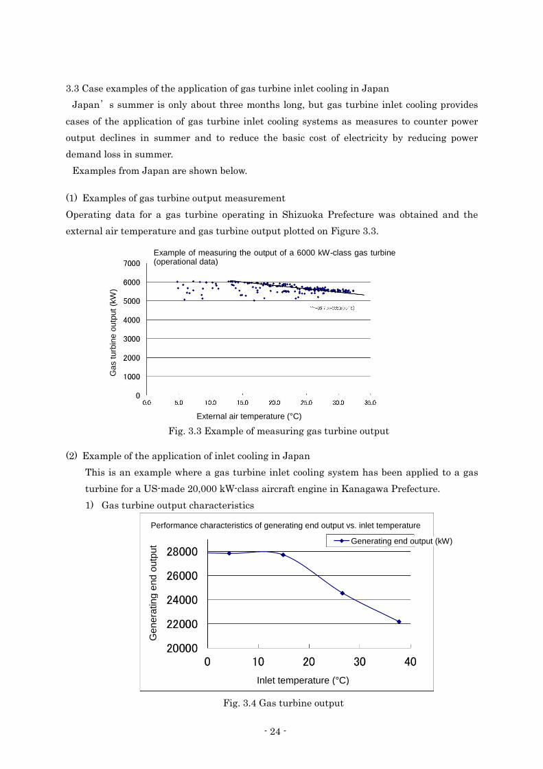
- 24 -
3.3 Case examples of the application of gas turbine inlet cooling in Japan
Japan’s summer is only about three months long, but gas turbine inlet cooling provides
cases of the application of gas turbine inlet cooling systems as measures to counter power
output declines in summer and to reduce the basic cost of electricity by reducing power
demand loss in summer.
Examples from Japan are shown below.
(1) Examples of gas turbine output measurement
Operating data for a gas turbine operating in Shizuoka Prefecture was obtained and the
external air temperature and gas turbine output plotted on Figure 3.3.
(2) Example of the application of inlet cooling in Japan
This is an example where a gas turbine inlet cooling system has been applied to a gas
turbine for a US-made 20,000 kW-class aircraft engine in Kanagawa Prefecture.
1) Gas turbine output characteristics
Fig. 3.3 Example of measuring gas turbine output
in Japan
Fig. 3.4 Gas turbine output
characteristics
Ga
s t
urb
ine
ou
tpu
t (k
W)
Example of measuring the output of a 6000 kW-class gas turbine (operational data)
External air temperature (°C)
Ge
ne
ratin
g e
nd
ou
tpu
t
Performance characteristics of generating end output vs. inlet temperature
Generating end output (kW)
Inlet temperature (°C)
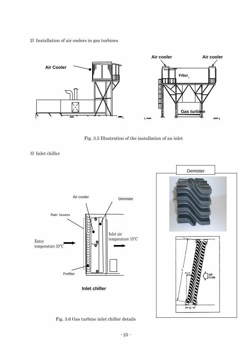
- 25 -
2) Installation of air coolers in gas turbines
3) Inlet chiller
Air Cooler
Air cooler
Filter
Gas turbine
Air cooler
Inlet chiller
Demister
Rain louvers
Prefilter
Air cooler
Demister
Fig. 3.5 Illustration of the installation of an inlet
chiller on a gas turbine
Fig. 3.6 Gas turbine inlet chiller details

- 26 -
4) Example of inlet chiller installation
The inlet chiller is installed on the
condition that the structure of the gas
turbine itself is not modified.
There are detailed contract conditions
between the gas turbine manufacturer
and the owner, and so modifications
were made in a way that did not
infringe on these conditions.
5) Example of measuring gas turbine output increase in summer
Unconditional output for inlet cooling 22,500 kW
Output status during inlet cooling operation 26,300 kW
Power output increase 3,800 kW
Daily output increase Approx. 92,000 KWh/day
ガスタービン吸気冷却適用効果比較
20000
22000
24000
26000
28000
1 2 3 4 5 6 7 8 9 10 11 12 13 14 15 16 17 18 19 20 21 22 23 24
時間
電力出力(kW)
2001年8月3日
2000年8月3日
Fig. 3.7 An inlet chiller attached to a gas turbine inlet
Fig. 3.8 Increases in power output for gas turbines
when using inlet cooling
Comparison of gas turbine inlet cooling effects
Pow
er
outp
ut
(kW
)
August 3, 2001
August 2, 2000
Time

- 27 -
6) Comparison of generated amount for each inlet-cooled month in Japan
The following shows a comparison of the power generation output for each month when
using inlet cooled operation in Japan.
The period when gas turbine inlet cooling is effective in Japan is between June and
September, but this shows that it is effective even for short periods.
Fig. 3.9 Comparison of increases in generated
amount for inlet-cooled gas turbines

- 28 -
3.4 Cogeneration system steam turbine output improvements
The cogeneration system and SPP power generation equipment at BKK are operated using
a steam turbine, which uses steam generated with a waste gas boiler. In addition to the
steam turbine, steam is also supplied to the users (steam for operating the steam inlet chiller
for the district cooling plant at BKK).
Generally, in a cogeneration system, steam is extracted from the interim stage of the steam
turbine, and increasing the amount of steam extracted will lower the steam turbine’s power
output.
The district cooling plant at BKK uses steam extracted at the interim stage of the steam
turbine to power the steam inlet chiller for the district cooling plant, and the cold-source
equipment configuration for the district cooling plant has an affect on the efficiency of the
cogeneration.
G G
Gas turbine
Waste gas boiler
Power supply
G
Natural gas
Waste gas boiler
Natural gas
Gas turbine
Steam
User Steam supply to district cooling plant
430℃, 60BarG
G
Steam turbine
Waste gas boiler
Steam extraction
Vapor absorption
Cooling
Typical example of a steam turbine using an SPP cogeneration system
Fig. 3.10 Improving steam turbine
output
Ste
am
turb
ine o
utp
ut (k
W)
Steam extraction volume

- 29 -
In terms of improving the energy efficiency of the cogeneration system and the district cooling
plant at BKK, studies will need to be made on whether creating a turbo chiller using cold
coolant water or creating an inlet chiller will be more efficient.

- 30 -
Reference Materials
1) Keisuke Yoshida, Keita Fujii, Akihito Kunihiro, Yasui Tomita, “Turbo Chiller Inlet
Cooling Systems for Large Gas Turbines for Power Generation,” GT Society, May 2014
(Inlet Cooling Special)
2) Takanobu Komuro, Eisaku Ito, Takashi Sonoda, Yasui Tomita, Kohei Hidaka, Seiji
Shibuya, “Increased Output of Gas Turbine Combined Power Generation Plants Through
Inlet Cooling in High Ambient Temperatures,” Mitsubishi Juko Giho, Vol. 47,No. 4 (2010),
pp. 49-54.

- 31 -
Chapter 4 Conditions for the Application of Inlet Cooling Systems
4.1 Climate conditions in Thailand
Thailand's climate is a monsoon one, with stark differences between the rainy season and the
dry season. The average annual temperature in Bangkok is 29.1°C and the average humidity
is 76.2%, making it hot and humid year-round. March through May are the hottest months,
when the outdoor temperatures can climb as high as 40°C.
The average temperature in the coolest month, December, is 17°C, and there are three
seasons: the dry season from November to February, the hot season from March to May, and
the green season (wet season) from June to October.
Data plotting the relationship between outdoor temperature and humidity in the Chonburi
region of Thailand is shown below. The planning conditions for inlet cooling systems are
believed to allow temperatures of 35°C and humidity of 40%. The Chonburi region has the
greatest concentration of industrial estates in the country. The data below is data from the
Thai Meteorological Department, plotting data using measurement values taken hourly for
365 days.
4.2 Natural gas costs
The results of interviews with the SPPs contacted for this survey regarding the purchasing
costs of natural gas are shown below.
Company A is located near Bangkok and Company B 300 km from Bangkok, and the gas
pipeline costs are believed to be assigned to the natural gas purchasing costs.
Natural gas costs
Company A 320 Baht/MMBTU
Company B 346 Baht/MMBTU
Fig. 4.1 Thai climate conditions Source: 2008 NOAA climate data Federal Climate Complex Data Documentation for Integrated Surface Data November 17, 2008 Location: Chonburi, Thailand
Table 4.1 Natural gas costs from interviews with SPPS

- 32 -
These costs will now be compared with those of Japan and other nations (MMBTU = 25m3,
1Baht = 3.63 yen)
For Company A, it works out as 46.4/m3.
A gas cost comparison for Thailand, Malaysia, China, and Japan is shown below.
Country Local gas unit Yen
conversion Notes
Malaysia Gas 16.07 RM/MMBTU 21.0 Gas Malaysia unit cost
Thailand 320 Baht/MMBTU 46.4 Interviews with SPPs
China 3RMB/M3 59.4 Individually investigated
Japan - 82.4 T Gas Corporation Package Type 1
Malaysia's gas costs are set lower than the market rate thanks to government subsidies.
4.3 Sales costs for generated power
The sales prices for power to EGAT and to industrial estates was obtained from
interviews with SPPs.
Table 4.3 Generated power costs for SPPs
Electricity sale price to EGAT
Electricity sale price to industrial estates
Company A 2.95 Baht/kWh 3.35 Baht/kWh
Company B Peak 3.7 Baht/kWh Off-Peak 2.9 Baht/kWh
Peak 3.5 Baht/kWh Off-Peak 2.1 Baht/kWh
0
10
20
30
40
50
60
70
80
90
Malaysia Thailand China Japan
Nat
ura
l ga
s cost
(ye
n/N
m3)
Table 4.2 Comparison of natural gas costs in different countries
Fig. 4.2 Comparison of natural gas costs in different countries

- 33 -
4.4 IPP and SPP CO2 emissions per unit
The ratio of fuel consumed through coal-fired power generation in Thailand is reported as
around 19.1%.
Fuel type Ratio
(%)
Renewables 15.1
Natural gas 64.6
Coal 9.5
Lignite 9.6
Fuel oil 1.11
Diesel 0.1
Fig. 4-3. Power generation fuel ratio in Thailand
The CO2 emissions per unit differs by fuel type and power plant generation efficiency. The
CO2 emissions per unit for current power generation efficiency and fuel type is shown below.
Table 4-4. CO2 emissions per unit by power generation category
Category
Power generation efficiency
CO2 emissions per unit
kg-CO2/kWh Coal fired power generation
41% 0.864
Oil-fired power generation
41% 0.695
LNG-fired power generation
41% 0.476
SPP class gas turbine combined cycle power generation
52.7%
0.371
IPP class gas turbine combined cycle power generation
56.7%
0.344
0.0
0.1
0.2
0.3
0.4
0.5
0.6
0.7
0.8
0.9
1.0
Coal fired powergeneration
Oil-fired powergeneration
LNG-fired powergeneration
SPP class gas turbinecombined cycle
power generation
IPP class gas turbinecombined cycle
power generation
CO
2em
issi
ons
per
unit (kg
-C
o2/
kWh)
Source: Summary of Thailand Power Development Plan 2012 - 2030 (PDP2010: REVISION 3)
Source: Calculated from Reference Material 3) for CO2 emissions per unit for thermal power generation, efficiency of gas turbine combined-cycle generation calculated by reporter, and calculated from Reference Material 4) Physical Properties of Natural Gas for gas turbine combined-cycle generation CO2 emissions per unit.
Fig. 4-4. CO2 emissions per unit by power generation category

- 34 -
The assessment of the CO2 reduction through the introduction of inlet cooling was based
on the following two points.
(1) The CO2 reduction effects through increasing the amount of energy generated from
gas turbine combined-cycle power plants with low CO2 emissions per unit and
reducing the amount of energy generated from coal-fired plants.
(2) Effects from improving the efficiency of gas turbine heat rates.
4.5 Power CO2 emissions per unit in Thailand
For the CO2 emission volume to use in this field survey, it was decided to use the figures
published by the Thailand Greenhouse Gas Management Organization (Public
Organization) (TGO; founded in 2007), an organ of the Thai government, as the TGO
works as the organization for approving and checking CDM projects.
Table 4.5 Carbon dioxide emission factors for power generation in Thailand: Source 4)
OM (Operating Margin): The emission factor for existing power generation
facilities. At present, the idea is to replace power
generation facilities that are linked to the grid, and
this will be used when considering the short-term
impact.
BM (Build Margin): The emission factor for the most recently-built
power plants. The idea is to replace power plants
that will be built in the future, and this will be used
when considering the long-term impact.
CM (Combined Margin): The average of the OM and the BM.
In this field survey, calculations used the TGO’s OM of 0.5994 kg-CO2/kWh

- 35 -
Reference Materials
1) Concerning Thermal Power Generation, Agency for Natural Resources and Energy,
February 2012
https://www.env.go.jp/council/06earth/y0613-11/ref04.pdf
2) Takanobu Komuro, Eisaku Ito, Takashi Sonoda, Yasui Tomita, Kohei Hidaka, Seiji
Shibuya, “Increased Output of Gas Turbine Combined Power Generation Plants Through
Inlet Cooling in High Ambient Temperatures,” Mitsubishi Juko Giho, Vol. 47,No. 4 (2010),
pp. 49-54.
3) “Survey of Lifecycle CO2 by Power Source,” Central Research Institute of Electric Power
Industry News No.468, August 2010.
4) Thailand Greenhouse Gas Management Organization (Public Organization): TGO,
Summary Report: The Study of Emission Factor for an Electricity System in Thailand
2010
5) Japan Finance Corporation, Japan Bank for International Cooperation, Guidelines for
Measurement, Reporting, and Verification of Greenhouse Gas Emissions in the Japan
Bank for International Cooperation’s Global Environmental Protection Work, Revised
February 2011.

- 36 -
Chapter 5 SPP Businesses: Field Study for the Application of Inlet Cooling Systems for Gas Turbine Combined Cycle Generators
5.1 Studied SPP gas turbine combined cycle plants
Regarding the study of the application of inlet cooling systems to SPP gas turbine combined
cycle generators, interviews were conducted with SPP businesses, getting them to note the
gas turbine combined cycle generator equipment to be surveyed, and the CO2 reduction
amount and economics if inlet cooling equipment was brought in for their gas turbines was
studied.
This study targeted the 40 MW-class equipment used by G Company and the 40 MW-class
equipment used by S Company that are some of the most commonly-used types in Thailand.
With SPPs, the power that can be sold to EGAT is required to be no more than 90 MW,
which businesses owning gas turbine combined cycle generation equipment between 110 MW
and 120 MW do not have any merit as even if they bring in inlet cooling equipment and boost
their output, they cannot sell all of the power unless the industrial estate’s electrical load is
at least around 40 MW. Therefore SPPs with sufficient load in industrial estates were
selected.
5.2 Assessment of CO2 reduction amounts through the introduction of inlet cooling systems
The effects of inlet cooling systems on gas turbine combined cycle generation equipment are
considered to be two-fold: a. the increase in power with little emission of carbon dioxide, and b.
the improvement of the generation heat rate for gas turbines.
[Effects of gas turbine inlet cooling ]
a. Electrical power increases (increases in the amount of power used with low CO2
emissions per unit)
Calculated using the following formulae.
𝐸𝐺𝐺𝑇𝐼𝑁𝐶 = 𝐸𝐺𝐺𝑇(𝑇𝑑) − 𝐸𝐺𝐺𝑇(𝑇(𝑚, 𝑑, ℎ)) (5.1)
𝐸𝐺𝑆𝑇𝐼𝑁𝐶 = 𝐸𝐺𝑆𝑇(𝐸𝐺𝐺𝑇(𝑇𝑑)) − 𝐸𝐺𝑆𝑇(𝐸𝐺𝐺𝑇(𝑇(𝑚, 𝑑, ℎ))) (5.2)
𝐸𝐺𝐼𝑁𝐶 = 𝐸𝐺𝐺𝑇𝐼𝑁𝐶 + 𝐸𝐺𝑆𝑇𝐼𝑁𝐶 (5.3)
𝐸𝐺𝐼𝑁𝐶𝑦 = ∑
𝑚=1𝑡𝑜12
∑ ∑ 𝐸𝐺𝐼𝑁𝐶
ℎ=1 𝑡𝑜 24𝑑=1 𝑡𝑜 31
(5.4)
𝐸𝑅𝑦,𝑒𝑠𝑡𝑖𝑚𝑎𝑡𝑒𝑑 = 𝐸𝐺𝐼𝑁𝐶𝑦 × (𝐹𝐸𝐸𝐿 𝐺𝑅𝐼𝐷 – 𝐹𝐸𝐸𝐿 𝐶𝑂𝑀) /1000 (5.5)
𝐸𝐺𝐺𝑇𝐼𝑁𝐶 Gas turbine power output increase amount (kW)
𝐸𝐺𝐺𝑇(𝑇) Gas turbine power output calculation function (kW)
where T is the inlet air temperature
𝐸𝐺𝑆𝑇𝐼𝑁𝐶 Steam turbine power output increase amount (kW)
𝐸𝐺𝑆𝑇(𝐸𝐺𝐺𝑇(𝑇)) Steam turbine power output calculation function (kW)

- 37 -
Used as the function for gas turbine output
𝐸𝐺𝐺𝑇(𝑇𝑑) Gas turbine power output at designed ambient temperature (15°C) (kW)
𝑇(𝑚, 𝑑, ℎ) Ambient temperature measurement value
𝐸𝐺𝐼𝑁𝐶 Combined power generation output increase amount (kW)
𝐸𝐺𝐼𝑁𝐶𝑦 Annual power output increase (kWh/year)
𝐸𝑅𝑦,𝑒𝑠𝑡𝑖𝑚𝑎𝑡𝑒𝑑 Annual CO2 reduction volume (ton-CO2/year)
𝐹𝐸𝐸𝐿 𝐺𝑅𝐼𝐷 Grid power CO2 emissions coefficient (kg-CO2/kWh)
Default value Ch. 4, Table 4.5 EFgrid,OM 0.5994 (kg-CO2/kWh)
𝐹𝐸𝐸𝐿 𝐶𝑂𝑀 Combined cycle CO2 generation coefficient (kg-CO2/kWh)
Default value Ch. 4, Table 4.4 SPP class 0.371 (kg-CO2/kWh)
y Calculation year
m Calculation month
d Calculation day
h Calculation hour
T Gas turbine design inlet air temperature
B Baseline
P Project
b. CO2 reduction through improvements in gas turbine heat rates from inlet cooling
𝐸𝐷𝐸𝐶 𝐻𝑅 = 𝐸𝐺𝐺𝑇(𝑇(𝑚, 𝑑, ℎ)) × (𝐻𝑅𝐶𝑂𝑀 𝐵 − 𝐻𝑅𝐶𝑂𝑀 𝑃) ÷ 𝐿𝐻𝑉𝐹𝑈𝐸𝐿 × 𝐹𝐸𝐹𝑈𝐸𝐿 (5.6)
𝐸𝐷𝐸𝐶 𝐻𝑅 𝑦 = ∑ ∑
𝑑=1 𝑡𝑜 30
∑ 𝐸𝐷𝐸𝐶 𝐻𝑅
ℎ=1 𝑡𝑜 24𝑚=1 𝑡𝑜 12
(5.7)
𝐸𝐷𝐸𝐶 𝐻𝑅 𝑦 Amount of CO2 reduction from gas turbine heat rate improvements
(kg- CO2/year)
𝐸𝐷𝐸𝐶 𝐻𝑅 Amount of CO2 reduction from gas turbine heat rate improvements
(kg-CO2/h)
𝐻𝑅𝐶𝑂𝑀 𝐵 Heat rate without inlet cooling (MJ/kWh)
𝐻𝑅𝐶𝑂𝑀 𝑃 Heat rate with inlet cooling (MJ/kWh)
𝐿𝐻𝑉𝐹𝑈𝐸𝐿 Natural gas calorific value (MJ/Nm3)
𝐹𝐸𝐹𝑈𝐸𝐿 Amount of CO2 generated from natural gas (kg- CO2/Nm3)

- 38 -
c. Economic benefits from increased power output due to inlet cooling
The annual power generation amount for combined cycle generation equipment is
calculated in (5.1)- (5.4).
(1) Power purchase increases
Increases in profitability from power output increases are calculated according to the
following formulae.
𝐶𝐸𝐿 𝐼𝑁𝐶 𝑦 = ∑ ∑
𝑑=1𝑡𝑜 30
∑ 𝐸𝐺𝐼𝑁𝐶
ℎ=1 𝑡𝑜 24𝑚=1 𝑡𝑜 12
× 𝐶𝐸𝐿 𝑈𝑁𝐼𝑇 (5.8)
𝐶𝐸𝐿 𝐼𝑁𝐶 𝑦 Amount of increase in annual power purchased (Bhat/year)
𝐶𝐸𝐿 𝑈𝑁𝐼𝑇 Power unit cost (Bhat/kWh)
(2) Fuel costs
𝐹𝑈𝐸𝐿𝐼𝑁𝐶 = 𝐸𝐺𝐺𝑇(𝑇(𝑚, 𝑑, ℎ)) × 𝐻𝑅𝐶𝑂𝑀 𝐵 − 𝐸𝐺𝐺𝑇(𝑇𝑑) × 𝐻𝑅𝐶𝑂𝑀 𝑃 ) ÷ 𝐿𝐻𝑉𝐹𝑈𝐸𝐿 (5.9)
𝐶𝐹𝑈𝐸𝐿 𝐼𝑁𝐶 𝑦 = ∑ ∑
𝑑=1 𝑡𝑜 31
∑ 𝐹𝑈𝐸𝐿𝐼𝑁𝐶 × 𝐶𝐹𝑈𝐸𝐿
ℎ=1 𝑡𝑜 24𝑚=1 𝑡𝑜 12
(5.10)
𝐹𝑈𝐸𝐿𝐼𝑁𝐶 Increase in natural gas consumption (Nm3/h)
𝐶𝐹𝑈𝐸𝐿 Natural gas unit cost (Bhat/Nm3)
𝐶𝐹𝑈𝐸𝐿 𝐼𝑁𝐶 𝑦 Amount of increase in annual gas costs (Bhat/year)
(3) Annual merits from the application of an inlet cooling system
IASCINC y = 𝐶𝐸𝐿 𝐼𝑁𝐶 𝑦 − 𝐶𝐹𝑈𝐸𝐿 𝐼𝑁𝐶 𝑦 (5. .11)
IASCINC y Merits from the introduction of an inlet cooling system (Bhat/year)
The amount of CO2 generated and the economic effects are assessed through running
simulations using characteristics data for gas and steam turbines as well as measurement
data and ambient conditions (external air temperature and humidity) for 24 hours a day, 365
days a year.
5.3 SPP class gas turbine combined cycle generation equipment: Assessment of the
application of inlet cooling systems
The results of studying the inlet cooling system with regard to the targeted SPP-class
combined cycle generation equipment are as follows.
(1) Study materials
G Co.’s 40 MW-class devices x 2 + ST combined cycle generation equipment
Materials 5.1

- 39 -
S. Co.’s 40 MW-class devices x 2 + ST combined cycle generation equipment
Materials 5.2
(2) CO2 reduction effects and expected return on investment (ROI)
System CO2 reduction ROI
G Co. GT x 2 + ST combined cycle generation equipment
39,922 tons-CO2/year
0.92 year
S Co. GT x 2 + ST combined cycle generation equipment
27,370 tons- CO2/Year
1.67 year
As shown above, the CO2 reduction effects differ even with the same scale of cogeneration
system. The 40 MW-class equipment from G Company is an engine used in large-scale
passenger aircraft by companies such as Airbus and Boeing (aircraft-use gas turbine).
Generally, aircraft-use gas turbines show significant improvements in heat rate and
generated output through the application of a gas turbine inlet cooling system, as they are
highly susceptible to the effects of ambient temperatures.
The engines used by SPPs in Thailand are mainly the gas turbines listed above, and in
addition are almost all the same 110 MW to 130 MW output capacity, so they can be
estimated by engine types when studying the CO2 reduction effects and return on investment
effects.
5.4 Points to note regarding the application of SPP class gas turbine combined-cycle
generation equipment inlet cooling systems
SPP power generation businesses
sell up to 90 MW of electricity to
EGAT as well as electricity, steam,
and cold water to industrial estates.
Therefore even if SPPs use inlet
cooling systems and boost their
outputs, the issue is whether a
system that allows them to sell this
extra power can be put into place.
Therefore it may not be possible
to sell all the extra generated
power, depending on the status of
the electricity users in the
industrial estate, even when it
becomes possible to use inlet
cooling systems for gas turbines.
Fig. 5.1 Illustration of power sales for
SPPs with gas turbine inlet cooling added
Pow
er
sale
s a
mo
un
t (M
W/h
) About
30 MW
About
70 MW
About 85 mW
Sale of power to EGAT
About
30 MW
No inlet cooling With inlet cooling
Sale of power to industrial estate

40
Materials 5.1
Model Case for the Application of Gas Turbine Inlet Cooling for G Company Product

41
1. Overview of the surveyed plant
The Thai company G Company, which operates SPPs in Thailand, has been asked to
select a plant for the field survey. A study was done of the inlet cooling systems for the
cogeneration system. The studied plant supplies steam and power to an industrial park.
The studied plant uses two 40 MW-class turbines made by G Company and a steam
turbine. Refer to the attachment for details of the system and the results of the CO2
reduction amount study.
Photo 1. Cogeneration system
Photo 3. Generator
Photo 2. Waste gas boiler
Photo 4. Gas turbine body

42
2. FS for Inlet Air Cooling (For the Thai domestic company G Company)
2.1. General
This document summarizes the power increase of the gas turbine combined power generation system of the Thai domestic company G Company.
2.2. Gas Turbine Combined Power Plant Configuration
Steam Turbine 38MW
Auxiliary Boiler 9 - 55t/h
50 BARG 430℃ Fuel
Fuel
Fuel
15.7kg/cm2
HRSG
HRSG
HRSG
Gas Turbine 42.1MW
ISO Condition
Gas Turbine 42.1MW
ISO Condition
Gas Turbine 42.1MW
ISO Condition
G
G
G
G
ATC-CPX III 45MW
EGAT Phase-1
Phase-2
MP Steam Supply
HP Steam Supply
Process demand 81.1t/h
44kg/cm2
Fig. 1 Gas Turbine Cogeneration System
Plant steam consumption for G Co.
Plant steam pressure and temperature for G Co.

43
2.3. Gas Turbine Data
General information shall be provide.
No. Item Information Unit Remarks
1 GT manufacture G Company
2 GT model 40 MW-class, 50 Hz
3 Installed GT number 2 set
4 Year of Start Operation 2009
5
Rated power output
42100 kW@5163 rpm kW ISO condition
kW Site condition
6
GT design ambient temperature
35
°C
Site condition
7
GT design ambient humidity
76
%
Site condition
8
Combustion airflow at design condition
130
Kg/S
Site condition
9
Fuel consumption at design condition
- Nm3/h
10 GT power generation efficiency
Heat-rate (LHV) 11588 kJ/kWh
%
11
HRSG Steam a. Temperature b. Pressure c. Steam Flow
430 50 barg 140
°C
Mpa barg Ton/h
2.4. Utility condition The feasibility of GT inlet air cooling system shall be calculated.
Item Data Unit
Fuel combustion heat 902.7565
MMBTU/Nm3 LHV(dry) BTU/SCF
Fuel Price 346 Baht/MMBTU
Generated power selling price to EGAT Peak = 3.7 Off-Peak = 2.9
Baht/kWh (*1)
Generating power selling price to industrial
Peak = 3.5 Off-Peak = 2.1
Baht/kWh (*1)
Water cost Service water = 23.75
Baht/m3

44
2.5. GT Inlet Air Cooling Application (1) Inlet temperature
By applying Gas Turbine Inlet Air Cooling System, compressor inlet temperature will be cooled down in the following condition.
Inlet Temperature
Original Temperature 35°C
Gas Turbine Inlet air Cooling System
15°C
(2) Power Increase check
Cooling the inlet temperature from 35°C to 15°C is expected to increase the power by 14.6%.
(3) Heat Rate Improve By applying inlet air cooling system, heat rate will be improved 3.7%.

45
2.6 Ambient air condition
The ambient temperatures of Thailand are plotted in Fig.4 The design temperature of inlet air cooling system can be decided at 35°C, 40%RH.
2.7 Chiller system planning for inlet air cooling system
a. Inlet air condition of air cooling coil GT design ambient temperature
35 degC
GT design ambient humidity
40%
Enthalpy of Intel Air
17kcal/kg
a. Outlet air condition of air cooling coil GT design ambient temperature
15 degC
GT design ambient humidity
100%
Enthalpy of Intel Air
9.9kcal/kg
Combustion Air Flow in design : 130 kg/s (<= Is it total of two ) Combustion Air Flow with Inlet Air Cooling 130kg/s x 1.146 =149 kg/s
Required cooling capacity = 149kg/s x (17 kcal/kg - 9.9 kcal/kg ) x 3600 /3024 = 1254 RT x 2 Gas Turbine = 2508RT
Fig.2 Ambient temperature conditions

46
2.8 Steam Turbine Steam Turbine characteristic is shown as follows.
Steam Steam Turbine Remarks
100t/h 23000 kW Ext Flow 0t/h
150t/h 37000 kW Ext Flow 0t/h
Ratio of increase in steam amount vs. increase in power output
= (37000kW-23000kW)/ (150t/h-100t/h) = 280kW/t

47
3. 2014 gas turbine output (Operation data)
(1) Monthly Power Output
GTG1
(kW) GTG2
(kW) STG (kW)
Jan 29,329,230 28,241,714 5,227,366
Feb 24,827,559 25,565,844 3,496,605
Mar 25,950,866 29,087,396 3,883,267
Apr 25,353,858 27,463,507 3,544,509
May 28,842,617 28,503,896 5,198,784
Jun 27,908,861 25,607,658 3,927,448
Jul 29,048,579 29,115,868 4,758,126
Aug 27,525,369 27,559,471 5,115,393
Sep 27,061,725 19,076,006 6,726,459
Oct 29,126,891 29,544,719 6,325,517
Nov 28,315,468 24,607,237 3,786,034
Dec 28,658,131 8,930,923 1,142,508
(2) Hourly Gas Turbine Output
GTG1 (MW)
GTG2 (MW)
Jan-14 39.4 38.0
Feb-14 36.9 38.0
Mar-14 34.9 39.1
Apr-14 35.2 38.1
May-14 38.8 38.3
Jun-14 38.8 35.6
Jul-14 39.0 39.1
Aug-14 37.0 37.0
Sep-14 37.6 26.5
Oct-14 39.1 39.7
Nov-14 39.3 34.2
Dec-14 38.5 12.0

48
Design Condition Ambient Temperature 35℃ Relative Humidity 40.%
Operating Condition With Inlet Air Cooling Ambient Temperature 15℃ Relative Humidity 100%
Psychrometric Chart
Atmospheric pressure
Ab
so
lute
hu
mid
ity
Pa
rtia
l w
ate
r vap
or
pre
ssu
re
Temperature

- 49 -
4 . Merit calculation of inlet air cooling system
The merits of using an inlet air cooling system are calculated by conducting simulations of a cogeneration system running 24 hours a day, 365 days a year, applying the annual climate conditions to the operating conditions of gas turbines using the formulae in (5.1) to (5.11).
(1) Ambient Temperature

- 50 -
(2) Gas Turbine Output without Inlet Air Cooling System (3) Power Increase of Gas Turbine x 2 by Inlet Air Cooling System

- 51 -
(4) Combined Cycle power increase by Inlet Air Cooling (5) Cooling Load by Inlet Air Cooling

- 52 -
[ Merit of Gas Turbine Inlet Air Cooling System ] Based on the yearly combined system calculation, the merit of Gas Turbine Inlet Air Cooling System will be as follows. Annual sales volume from the grid and annual generated amount before and after the application of the gas turbine inlet air cooling system.
Item Before application After application
GTCC annual generated power
1,073,475 MWh/ year 1,186,013 MWh/year
Sales from grid 112,538 MWh/ year 0 MWh/year
GTCC CO2 emissions 415,117 tons - CO2 / year 442,605 tons-CO2/year
Grid CO2 emissions 67,410 tons - CO2 / year 0 tons-CO2/year
Year Cost Merit of GT Inlet Air Cooling 212,082,599 Bhat/Year CO2 Reduction 39,922 ton- CO2 /Year
Chiller System Capacity 4,000RT Chiller Budgetary Cost 1,500US$/RT Total Cost 6 mill-US$ Currency 32.57Bhat/US$
Chiller System 4000RT
Budgetary Cost for IACS 1500US$/RT
US$6,000,000
195,420,000Bhat
Investment Recovery 0.97 Year

- 53 -
Materials 5.2
Model Case for the Application of Gas Turbine Inlet Cooling for S Company Product

- 54 -
1. Overview of the surveyed plant
A study was conducted on the economics issue after getting an SPP company with German
investment to provide the planning requirements for the application of gas turbine inlet air
cooling. The studied plant uses two 40 MW-class turbines made by S Company and a steam
turbine. Refer to the attachment for details of the system and the results of the CO2
reduction amount study. The client for this study owns five SPP power plants with the same
specifications.
Rating Gas
Turbine
Steam
Turbine
Max
output
Designed
external
temp
Max
power
output
Average
power
demand
Designed
steam
supply
EGAT
power
supply
Industrial
estate
142.1
MW 50 MW x 2
42.1 MW x
1
132
MW 15°C
128
MW
104
MW 30t/h
Av. 80 MW
Max 90
MW
Av. 24 MW
Max 38
MW

- 55 -
2. FS for Inlet Air Cooling for (for the German B Company)
2.1 General
This document summarizes the power increase of gas turbine combined power generation system of the German B Company.
2.2 Gas Turbine Combined Power Plant Configuration (1) Rated performance
No. Item Information Unit Remarks
1 GT manufacture S Co/
2 GT model 40 MW-class
3 Installed GT number 2 set
4 Year of Start Operation 2013
5 Reted power output 48,845 kW
6 GT design ambient temperature 15 degC
7 GT design ambient humidily 76 %
8 Combustion airflow at design condition
- Kf/S
9 Fuel consumption at design condition
9.256 SCF/kW
h
10 GT power generation Heat Rate (LHV)
9,727 kJ/kWh
11
HRSG Steam (LP) a. Temperature b. Pressure c. Steam Flow
245.9 8.97 11.88
degC bara Ton/h
12
HRSG Steam (HP) a. Temperature b. Pressure c. Steam Flow
514.2 79.3
64.56
degC bara Ton/h
Fig.1 Gas Turbine Combined Cycle Configuration

- 56 -
(2) Power Increased by Gas Turbine Inlet Air Cooling The power output increase will be different by the ambient temperature but we can expect to see an increase in 8 MW power by cooling the inlet air temperature from 35°C to 15°C.
(3) Heat Rate Improvement Heat rate will be improved from 10.09MJ/kW to 9.6MJ/kW (around 4.8%)
2.3 Steam Turbine Output Characteristic Steam Turbine output is given below. Steam turbine output 14MW at steam flow 50t/h Steam turbine output 30MW at Steam flow 100t/h Steam output increase rate = (30MW-14MW) / (100t/h – 50t/h) = 0.32MW/ton-steam 2.4 Required Air Cooling Capacity
(1) Air Flow As there was no air flow condition, we assume air flow 3.55kg/MW based on LM6000 Air flow = 3.55kg/MW x 47MW = 166.85kg/s
(2) Ambient air condition
The ambient temperature of Thai country is plotted in fig.2 The design temperature of inlet air cooling system can be decided 35℃ 40%.
Fig.2 Ambient temperature condition

- 57 -
2.5 Chiller System planning for Inlet Air Cooling System
a. Inlet air condition of air cooling coil GT design ambient temperature
35 degC
GT design ambient humidity
40%
Enthalpy of Intel Air
17kcal/kg
a. Outlet air condition of air cooling coil GT design ambient temperature
15 degC
GT design ambient humidity
100%
Enthalpy of Intel Air
9.9kcal/kg
Combustion Air Flow with Inlet Air Cooling 130kg/s x 1.146 =149 kg/s x 1 Gas Turbine
Required cooling capacity = 166.85kg/s x (17 kcal/kg - 9.9 kcal/kg ) x 3600 /3024 = 1410 RT x 2 Gas Turbine = 2800RT
2.6 Utility condition
The feasibility of GT inlet air cooling system shall be calculated. Messer. You are requested to provide the following condition.
Item Data Unit
Average fuel heating value (HHV) 996 MMBTU/SCF
Fuel Price 320 Baht/MMBTU
Generated power selling price to EGAT
2.95 Baht/kWh (*1)
Generating power selling price to industrial
3.35(for 11kV) Baht/kWh (*1)
Water cost 20 Baht/m3

58
Psychrometric Chart
Design Condition Ambient Temperature 35℃ Relative Humidity 40.% Operating Condition
With Inlet Air Cooling Ambient Temperature 15℃ Relative Humidity 100%
Psychrometric Chart (Atmospheric pressure 760mmHg)
Temperature

- 59 -
2.7 Merit calculation of Inlet air cooling system
The merits of using an inlet air cooling system are calculated by conducting simulations of a cogeneration system running 24 hours a day, 365 days a year, applying the annual climate conditions to the operating conditions of gas turbines using the formulae in (5.1) to (5.11).
(1) Ambient Temperature

- 60 -
(2) Gas Turbine Output without Inlet Air Cooling System (3) Power Increase of Gas Turbine x 2 by Inlet Air Cooling System (4) Combined Cycle power increase by Inlet Air Cooling

- 61 -
(5) Cooling Load by Inlet Air Cooling

- 62 -
[ Merit of Gas Turbine Inlet Air Cooling System ] Based on the yearly combined system calculation, the merit of Gas Turbine Inlet Air Cooling System will be as follows. Annual sales volume from the grid and annual generated amount before and after the application of the gas turbine inlet air cooling system.
Item Before application After application
GTCC annual generated power
979,872 MWh/year 1,070,316 MWh/year
Sales from grid 90,444 MWh/year 0 MWh/year
GTCC CO2 emissions 396,611 tons- CO2/year
423,417 tons- CO2/year
Grid CO2 emissions 54,176 tons- CO2/year 0 tons- CO2/year
Year Cost Merit of GT Inlet Air Cooling 117,110,352 Bhat/Year CO2 Reduction 27,370 ton- CO2/Year
Chiller System Capacity 4,000RT Chiller Budgetary Cost 1,500US$/RT Total Cost 6 mill-US$ Currency 32.57Bhat/US$
Chiller System 4000RT
Budgetary Cost for IACS
1500US$/RT
US$6,000,000
195,420,000Bhat
Investment Recovery 1.67Year

- 63 -
・Chapter 6 Drawing up of MRV Methodology (draft) and PDD
(draft)
6.1 MRV Methodology (draft)
(1) Title of Methodology
”Application of Inlet Air Cooling System to Cogeneration Plant at IPP and SPP”
(2) Definition of Terms
Term Definition
Gas Turbine
Combined Power
Generation System
A power generation system designed to efficiently generate
power by driving steam turbines using the exhaust heat
after power is generated by gas turbines.
Inlet Air Cooling
System
In a gas turbine power generation system, this is designed
to increase power generation by increasing the intake air
volume through cooling the intake air with a chiller.
Cogeneration Plant In a power generation plant using fossil fuel, this is
designed to generate power and supply heat (hot water,
cold water) simultaneously. IPP
Independent Power Producer
SPP Small Power Producer
(3) Outline of the Methodology
1) GHG reduction means
By adding an inlet air cooling system to the existing gas turbine combined power
generation system, its power generation will be increased. As the carbon dioxide trip
generation rate of a gas turbine combined power generation system is greatly
improved compared to that of the utility grid in general, the carbon dioxide generation
amount will be reduced by replacing the electricity power from the utility grid with the
amount of power generation increased by the inlet air cooling system.
In addition, the carbon dioxide emissions will also be reduced, as the generation
efficiency of the gas turbine combined power generation system is improved and the
fuel consumption is reduced by decreasing the intake air temperature in the inlet air
cooling system.
2) Calculation method of baseline emission
The baseline emission is defined as the carbon dioxide emissions caused by the
fuel used for power generation at a target gas turbine combined power
generation system.
3) Basic concept of the project emission
The project emission is defined as the amount obtained by subtracting the
carbon dioxide generation amount reduced at the utility grid side when the
increased amount of power generation through an inlet air cooling system is
supplied to the utility grid, from the carbon dioxide emission when the inlet air
cooling system is added to the target gas turbine combined power generation
system.
The increased amount of power generation through an inlet air cooling system is
defined as the net increased amount of power generation that is obtained by

- 64 -
subtracting the consumed power (such as the power for driving chillers) under the
project scenario from the actually increased amount of power generation.
4) The referenced MRV methodology
J-MRV The Guideline for Measurement, Reporting, Verification of the
Reduction Amount of Greenhouse Gas Emission in the Global
Environmental Conservation Business of the Japan Bank for
International Cooperation
(4) Requirements for Qualification
This methodology is applicable to a project satisfying all of the following
requirements.
Requirement 1: The target power generation system shall be an SPP or IPP gas
turbine combined cycle power generation system installed in
Thailand.
Requirement 2: The target system shall be a gas turbine power generation system
with an inlet air cooling system.
Requirement 3: The target system shall be capable of selling the electricity,
increased by the added inlet air cooling system, to the utility grid or
demanders in the vicinity.
(5) Emission Source and GHG Type
1) Baseline emission
Emission Source Type of GHG
The emission caused by fuels consumed for power
generation at a gas turbine combined power generation
system
CO₂
2) Project emission
Emission Source Type of GHG
The emission that is obtained by subtracting the
emission from the increased power under a project
activity assumed to be generated in the country using an
average means, from the emission caused by the fuels
consumed for power generation in the gas turbine
combined cycle power generation system added with an
inlet air cooling system in the project activity.
CO₂
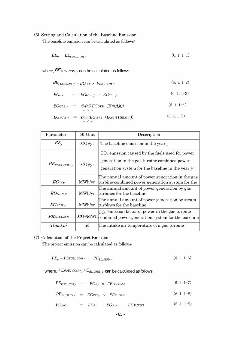
- 65 -
(6) Setting and Calculation of the Baseline Emission
The baseline emission can be calculated as follows:
BEy BEFUEL,COM y (6.1.1-1)
where, BEFUEL,COM y can be calculated as follows:
BEFUEL,COM y EG B y x FEEL COM B (6.1.1-2)
EGB y = EGGT B y + EGST B y (6.1.1-3)
EGGT B y = EGGT B(T(m,d,h)) (6.1.1-4) m d h
EGST B y =EGST B(EGGT(T(m,d,h)) (6.1.1-5) m d h
(7) Calculation of the Project Emission
The project emission can be calculated as follows:
PEy PEFUEL COM y - PEEL,GRID y (6.1.1-6)
where, PEFUEL COM y , PEEL,GRID y can be calculated as follows:
PEFUEL,COM y = EGP y x FEEL COM P (6.1.1-7)
PEEL,GRID y = EGINC y x FEEL GRID (6.1.1-8)
EGINC y = EGPy ― EGy ― ECTURBO (6.1.1-9)
Parameter SI Unit Description
BEy tCO2/yr The baseline emission in the year y
BEFUEL,COM y
tCO2/yr
CO2 emission caused by the fuels used for power
generation in the gas turbine combined power
generation system for the baseline in the year y
EG y
MWh/yr
The annual amount of power generation in the gas
turbine combined power generation system for the
baseline EGGT B y
MWh/yr
The annual amount of power generation by gas
turbines for the baseline
EGST B y
MWh/yr
The annual amount of power generation by steam
turbines for the baseline
FEEL COM B
tCO2/MWh CO2 emission factor of power in the gas turbine
combined power generation system for the baseline
T(m,d,h) K The intake air temperature of a gas turbine

- 66 -
EGP y = EGGT P y + EGST P y (6.1.1-10)
EGGT P y = ΣΣΣEGGT P(Td) (6.1.1-11) m d h
EGST P y = ΣΣΣEGST P(EGGT p(Td))) (6.1.1-12) m d h
Parameter SI Unit Description
PEy
tCO2/yr CO2 emission for the project in the year y
PEFUEL COM y
tCO2/yr
CO2 emission caused by the fuels consumed at a
gas turbine combined power generation system for
the project in the year y
PEEL,GRID y
tCO2/yr CO2 emission when the amount of power
generated under the project and increased in the
year y is supplied from the utility grid EGINC y MWh/yr The annual amount of power generation that is
increasing in the project activity
ECTURBO
MWh/yr
The amount of power consumed by the turbo chiller
operating for an inlet air cooling in the project
activity
FEEL GRID
tCO2/MWh CO2 emission factor of the average power supplied
from the utility grid
EG y
MWh/yr
The annual amount of power generation by the gas
turbine combined power generation system for the
project
EGGT P y MWh/yr The annual amount of power generation by gas
turbines for the project
EGST P y MWh/yr The annual amount of power generation by steam
turbines for the project
Td K The design temperature for the gas turbine inlet air
(8) Leakage
Leakage shall not be considered unless any noticeable effect is identified.
(9) Calculation of the GHG Emission Reduction Amount
The GHG emission reduction amount can be calculated as follows:
ERy ( BEy PEy )x ETAOPE x ETALOAD (6.1.1-13)
Parameter SI Unit Description
ERy t CO2 /yr The estimated CO2 emission reduction amount in
the year y ETAOPE - Operation rate of the project system in the year y
ETALOAD - Load factor of the project system in the year y

- 67 -
(10) Explanation of Data as Fixed Values, Parameters, and Subscripts
For (6) and (7) mentioned above, the data to be fixed in advance and its source, as well
as parameters and subscripts are described in the following table.
Parameter &
Subscript
SI Unit Description
x - Crediting period
y - A certain years (1 to x) during the crediting period
m - Month
d - Days
h - Hours
B - Baseline
P - Project
T
K
Air inlet temperature
Td K Design inlet temperature
EL - Electric power
FUEL - Fuel
COM - Combined power generation system
GT - Gas turbine
ST - Steam turbine
GRID - Utility grid
INC - Increased amount
ETA - Ratio
LOAD - Load
OPE - Operation
(11) Data Parameters to be Monitored
For (6) and (7) mentioned above, the data parameters that should be monitored to calculate
the GHG emission reduction amount are as follows:
Parameters SI Unit Description
FEEL GRID
tCO2/MWh
CO2 emission factor for the average electric power supplied
by the grid
- Default value (0.599 t- CO2 /MWh)
FEEL COM B
tCO2/MWh CO2 emission factor for the electric power from the gas
turbine combined power generation system for the baseline
FEEL COM P
tCO2/MWh CO2 emission factor for the electric power from the gas
turbine combined power generation system for the project

- 68 -
T
K
Gas turbine air inlet temperature
- Measurements by a thermometer
EGy
MWh/yr
The annual amount of power generation of the gas turbine
combined power generation system for the baseline
- Calculated back from the annual amount of power
generation for the project and the air inlet temperature T
ETAOPE - Operation rate of the project system in the year y
- Operation record of the power generation system
ETALOAD - Average load factor of the project system in the year y
- Operation record of the power generation system
FEEL COM P
tCO2/MWh CO2 emission factor for the electric power from the gas
turbine combined power generation system for the project
- Deduced from the annual amount of power generation
and the fuel consumptions described in the power generation
system record

- 69 -
(12) Monitoring Plan and Monitoring Report
Sheet (and Effect Evaluation Sheet) Unit Parameter Source, etc.
tCO2/yr ER y , estimated
- ETA OPE - ETA LOAD
TJ/Gg(MJ/kg) J-MRV Guideline kgGHG/TJ J-MRV Guideline
CO2 Emission Factor of Fuel (LNG) tCO 2 / Nm3 Average CO2 Emission Factor of Grid 0.599 tCO 2 /MWh FE EL GRID *1
tCO 2 /MWh FE EL COM B tCO 2 /MWh FE EL COM P
tCO 2 /yr BE y MWh/yr EG B
y Baseline Generation Efficiency %
tCO 2 /MWh FE EL COM B Baseline Fuel Consumption Nm3 Calorific Value of Fuel for Baseline (LHV) 38.06 MJ/N m3 *1 CO2 Emission Factor of Fuel for Baseline 2.070 kg-CO 2 /Nm3 *1
tCO 2 /yr PE y Emission from Fuel Used for Power Generation in Project Activity tCO 2 /yr PE FUEL COM y
MWh/yr EG P y Generation Efficiency in Project Activity %
tCO 2 /MWh FE EL COM P Project Fuel Consumption Nm3/yr Calorific Value of Fuel for Project (LHV) 38.06 MJ/N m3 *1 CO2 Emission Factor of Fuel for Project 2.070 kg-CO 2 /Nm3 *1
Emission when Increased Power Generation in Project Activity is Supplied from Grid tCO 2 /yr PE EL,GRID y Annual Power Generation Amount Increased in Project Activity MWh/yr EG INC y Average CO2 Emission Factor of Grid 0.599 tCO 2 /MWh FE EL GRID *1
*1:TGO Report SUMMARY REPORT THE STUDY OF EMISSION FACTOR FOR ELECTRICITY GENERATION OF THAILAND IN YEAR 2010
Monitoring Item
Target Plant Name
Ⅰ.Effect of Inlet Air Cooling
4. Calculation Result of Emission in Project Activity
Baseline Emission Baseline Annual Power Generation Amount
CO2 Emission Factor for Baseline Power Generation System
1. Calculation Result of Reduction Amount for Emission
2. Selected Default Values, etc
3. Calculation Result of Baseline Emission
Reduction Amount for Emission
System Operation Rate System Load Factor
CO2 Emission Factor of Baseline Power Generation System CO2 Emission Factor of Power Generation System for Project Activity
CO2 Emission Factor of Power Generation System in Project Activity
Calorific Value of Fuel (LNG) CO2 Emission Factor of Fuel (LNG)
Emission in Project Activity
Annual Power Generation Amount in Project Activity
CO2 Emission Factor of Fuel (LNG) CO2 Emission Factor of Fuel (LNG)

- 70 -
6.2 PDD (draft) Joint Crediting Mechanism Project Design Document Form Note: This JCM Project Design Document (PDD) is drafted as the result of the GEC’s JCM Feasibility Study Programme in JFY2013. Therefore, this draft PDD is not officially approved by any governments involved in JCM, and is subject to change in the future.
A.1. Name of Project
A.2. Outline of Project and Applicable Technology and/or Actions
A.3. Implementation Location of the Project (incl. longitude and latitude)
Country Thailand
State or Province Suwannaphum Suvarnabhumi, Bangkok
Longitude and Latitude Long. 100 deg. and 34 min. east, Lat. 13 deg. and 44 min. north
A.4. Participants in the Project
Thailand To be decided
Japan Research Institute of Global Environmental Strategies, Mitsubishi Heavy Industries, Ltd.
A5 Duration of the Project
Starting of Project To be decided
Estimated duration of the project 10 years
A. Description of Project B.
Application of Inlet Air Cooling System to Gas Turbine Cogeneration Plant at IPPs, SPPs
The purpose of the proposed JCM project is, for a cogeneration plant in Thailand and a local cooling plant at the Thai international airport, to improve energy efficiency by introducing an inlet air cooling system for gas turbines and a highly efficient turbo chiller, and to reduce energy-derived carbon dioxide emissions.
Specifically, the effect and feasibility of the following two types of systems are examined.
(1) With SPPs and IPPs as the target in Thailand, an inlet air cooling system will be added to the gas turbines to increase power output of the combined power generation system and improve generation efficiency, as well as to reduce carbon dioxide emissions through power supply with less CO2 trip generation rate to the utility grid.
(2) With the local cooling plant at the Suwannaphum Suvarnabhumi International Airport as the target of a typical cogeneration plant, the existing absorption chiller will be replaced by a turbo chiller to increase the amount of power generation using the surplus steam, and electricity with less CO2 trip generation rate will be supplied to the grid to reduce carbon dioxide emissions.

- 71 -
A6 Contribution from Advanced Countries
B.1. Selection of Methodology
Applicable Methodology JCM-JP-**-***
Version number Ver. **
B.2. Explanation on How the Project will Satisfy Qualification Requirements of the
Approved Methodology
Qualification Criteria
Explanation of the Methodology Project Information
Criterion 1 The target power generation system shall be an SPP or IPP gas turbine combined cycle power generation system in Thailand.
In Thailand, Thai companies have been developing many SPP businesses in partnership with overseas companies, and thus there are many candidate systems.
Criterion 2 The target system shall be applicable for an inlet air cooling system added to the gas turbine power generation system.
Many of SPP business operators have adopted a gas turbine plant that is applicable for inlet air cooling.
Criterion 3 The target system shall be capable of selling the increased electricity, which is obtained from the added inlet air cooling system, to the utility grid or to the demanders in the vicinity.
The inlet air cooling system is a proven and established technology in Japan.
C.1. All Emission Sources and Relevant Greenhouse Gases Relating to the Project
All emission sources of greenhouse gases relating to the JCM project
Current Emission Emission Source Greenhouse Gas
Fuel for power generation CO2
Project Emission Emission Source Greenhouse Gas
Fuel for power generation CO2
In this project, Japan will provide advanced technologies for high-efficient power generation and chiller system. In addition, know-how on application and operation technologies for efficiency improvement of the similar systems will also be taken over.
B. Application of Approved Methodology
C. Calculation of the Emission Reduction Amount

- 72 -
C.2. Chart of All Emission Sources and Monitoring Points Relating to the Project
C.3. Estimated Amount of
Emission Reduction in Each Year (for each target plant)
Year Current Emissions (tCO2e)
Evaluation of Emissions after
Project Implementation
(tCO2e)
Estimated Phenomenon in
Emissions (tCO2e)
1st Year 410,000 390,000 20,000
2nd Year 410,000 390,000 20,000
3rd Year 410,000 390,000 20,000
4th Year 410,000 390,000 20,000
5th Year 410,000 390,000 20,000
Legal Request for the Project on Environmental Effect Evaluation
N/A
E.1.Request from Local Stakeholders
E.2. Summary and Review of Comments Received
N/A
Reference lists to support descriptions in the PDD, if any.
D. Evaluation on Environmental Effects
E. Discussions with Local Stakeholders
N/A
No requests have been received.
F. References
INLET AIR COOLING SYSTEM
GAS TURBINE HEAT RECOVERY STEAM GGENERATOR
STEAM TURBINE

- 73 -
Attachments PDD Revision History
Version Year and month date Contents revised
01.00 March 3, 2015 First Edition
Monitoring Sheet (and Effect Evaluation Sheet)
SPP-A SPP-B Unit Parameter Source, etc.
27333.1 39887.2 tCO2/yr ER y ,estimated
1.0 1.0 - ETA OPE
1.0 1.0 - ETA LOAD
38.06 38.06 MJ/Nm3 *1
Average CO2 Emission Factor of Grid 0.599 0.599 tCO2/MWh FE EL GRID *1
397,155 415,689 tCO2/yr BE y
979,872 1,073,475 MWh/yr EG B y
0.405 0.387 tCO2/MWh FE EL COM B
Baseline Fuel Consumption 191,862,558 200,815,870 Nm3
Calorific Value of Fuel for Baseline (LHV) 38.06 38.06 MJ/Nm3 *1
CO2 Emission Factor of Fuel for Baseline 2.070 2.070 kg-CO2/Nm3 *1
369,822 375,802 tCO2/yr PE y
Emission from Fuel Used for Power Generation in Project Activity 423,998 443,212 tCO2/yr PE FUEL COM y
1,070,316 1,186,013 MWh/yr EG P y
0.396 0.374 tCO2/MWh FE EL COM P
Project Fuel Consumption 204,830,100 214,112,054 Nm3/yr
Calorific Value of Fuel for Project (LHV) 38.06 38.06 MJ/Nm3 *1
CO2 Emission Factor of Fuel for Project 2.070 2.070 kg-CO2/Nm3 *1Emission When Generation Amount Increased in Project Activity is Supplied to Grid 54,176 67,410 tCO2/yr PE EL,GRID y
Annual Generation Amount Increased in Project Activity 90,444 112,538 MWh/yr EG INC y
Average CO2 Emission Factor of Grid 0.599 0.599 tCO2/MWh FE EL GRID *1
*1:TGO Report SUMMARY REPORT THE STUDY OF EMISSION FACTOR FOR ELECTRICITY GENERATION OF THAILAND IN YEAR 2010
Reference value
Measurement value (Predicted value)
Target Plant Name
CO2 Emission Factor of Power Generation System in Project Activity
Calorific Value of Fuel (LNG)
Emission in Project Activity
Annual Generation Amount in Project Activity
Ⅰ.Effect of Inlet Air Cooling
4. Calculation Result of Emission in Project Activity
Baseline EmissionAnnual Baseline Power Generation AmountCO2 Emission Factor of Baseline Power Generation System
1. Calculation Result of Reduction Amount for Emission
2. Selected Default Values, etc.
3. Calculation Result of Baseline Emission
Reduction Amount for Emission
System Operation RateSystem Load Factor

- 74 -
・Chapter 7 Specific Financing, Construction, and Operation Plan,
Implementation System, etc. for Project Implementation
Specific financing, construction, and operation plan, implementation system and so on are
examined for project implementation.
7.1 Implementation Process of Gas Turbine Inlet Air Cooling system
The project for the SPP gas turbine inlet air cooling system in Thailand is assumed
as follows:
(1) Qualification for JCM requirements for SPP business operators of the gas turbine
inlet air cooling system
Qualification Detailed Requirement Explanation for the Project
Requirement 1
•Qualification of the proposed
project and applicability of the JCM methodology to the project shall be easily determined by a
“checklist”.
An explanation for MRV and PPD is presented in Chapter 8 of this FS.
Data (Parameter)
•Project participants shall be able
to understand the data necessary for calculating the amount of emission reduction and absorption of greenhouse gases through the JCM methodology, using a parameter list.
•Default values of the nation and
those specific to the sectors shall be provided in advance.
When the gas turbine inlet air cooling system is applied to the SPP power generation system, the following action will allow for evaluation of the effective reduction amount. - Existing power generation system All operation records are made from the central monitoring system. - Added gas turbine inlet air cooling system A monitoring device and an operation recorder will be installed Thailand Greenhouse Gas Management Organization (Public Organization): TGO publishes the CO2 trip generation rate of power generation in Thailand every year.
Calculation
- With a previously prepared spreadsheet, the amount of greenhouse gas emission reduction and absorption can be automatically calculated according to the methodology, by filling in the values corresponding to the parameters.
An explanation for MRV and PPD is presented in Chapter 8 of this FS.
As mentioned above, qualification for the JCM requirements is considered to be satisfied
by SPP business operators in applying the gas turbine inlet air cooling system.
Table-7.1 Considerations on Qualification for SPP Gas Turbine Inlet Air Cooling System

- 75 -
No. ofEquipment No. Equipment Name Desicription UnitsECC-1,3,5,7 Turbo Chiller Capacity 1000RT x 4 units
Chilled Water Flow Rate 432m3/hChilled Water Temperature Inlet 13℃/Outlet 6℃ 4Cooling Water Flow Rate 710m3/hCooling Water Temperature Inlet 30℃/Outlet 35℃
CT-1,4 Cooling Tower Cooling Water Flow Rate 750m3/h 4Cooling Water Flow Rate 35℃/30℃Wet Bulb Temperature 28℃
CP-1,4 Chilled Water Pump Chilled Water Flow Rate 432m3/h 4Pump Head 40mAq
CDP-1,8 Cooling Water Pump Cooling Water Flow Rate 730m3/h 4Pump Head 30mAq
(2) For this feasibility study, only two types of gas turbines for SPP power generation
operators are available in Thailand, and each of them has an inlet air cooling system
with the cooling capacity of 14.1 MW (4,000 RT).
Characteristics of two types of the gas turbines (manufactured by G Company in the
U.S and S Company in Germany) have already been analyzed in this feasibility study,
and a detailed design can be accomplished for the inlet air cooling system.
The gas turbine inlet air cooling system shall be of a modular unit composed of chiller
systems, pumps, and a cooling tower.
(3) Schedule for Inlet Air Cooling System
Generally, a project schedule depends on the delivery time of equipment. The
manufacturing schedule of the major equipment is as follows:
Equipment Type Duration of Manufacturing
Chiller System 6 months
Pump 4 months
Cooling Tower 4 months
Power Substation 6 months
Gas Turbine Inlet Air Cooling System Module
Cooling Tower
Chiller System Installation Module
Arrangement of Chiller Systems in the Gas Turbine Inlet Air Cooling System Module
Fig. 7.1 Outline Image for SPP Gas Turbine Inlet Air Cooling System
Chiller System Chiller System

- 76 -
2015 2016No Item May June July Aug Sept Oct Nov Dec Jan Feb Mar
1 Detail DesignDetail Design for EquipmentDetail Design for PlumbingDetail Design for Electricity/Instrument.
2 Arrangement & ManufacturingTurbo ChillerInlet Air CoolerPumpCooling TowerPiping PartsSteel FramePower Substation
3 Field ConstructionConstruction WorksPlumbing WorksCooling Tower AssemblyPower Substation InstallationElectric WorksChiller Installation
4 Trial OperationPower SubstationChiller Trial Operation
5 Start of Operation
7.2 Implementation System
For the gas turbine inlet air cooling system, the equipment that cannot be procured
in Thailand and other ASEAN countries include turbo chiller systems, inlet air cooling
systems, and system control systems; however, others can be procured there.
In implementation, the following structure is supposed to be built.
[Considerations on the structure mentioned above]
1) Reliability in the ordering system to Japanese manufacturers for the major
equipment.
such as turbo chiller systems and control systems, as well as ensuring of quality
2) Construction works, etc.
Ordering to the field construction companies
Fig. 7.2 Construction Schedule for SPP Gas Turbine Inlet Air Cooling System
Consortium Leader Japanese Companies Japanese Project Consultants
SPP Business Operators in Thailand
Turbo Chiller system Detailed Design Plan for
Gas Turbine Inlet Air Cooling System
System Control
International Consortium
Field Construction Company Piping, Electricity, Instrumentation
Order to Japanese Makers Field Construction Civil Engineering Works Remodeling Works for Gas
Turbine
MRV Support JCM-specific Consultants in Japan

- 77 -
7.3 Financing Plan
In starting up of the JCM subsidy business, it will be a problem to secure the
implementation cost shared by customers, accounting for 50% of the fund. As
companies implement their business on the following steps in general, about six
months are required to implement the project through the internal approval.
1. Development of a plant/equipment investment plan by the drafting division
↓
2. Application for budget by the drafting division
↓
3. Assessment by the budget investment management division
↓
4. A next-year budget meeting
↓
5. Budget determination (approved by the board of directors)
As SPP business operators need to find the prospect of securing their own funds for
50% so as to roll out a subsidy business using the JCM subsidy at present, it will be
important to secure the time and budget for clearing this problem. Business
profitability evaluation is shown on the next page.
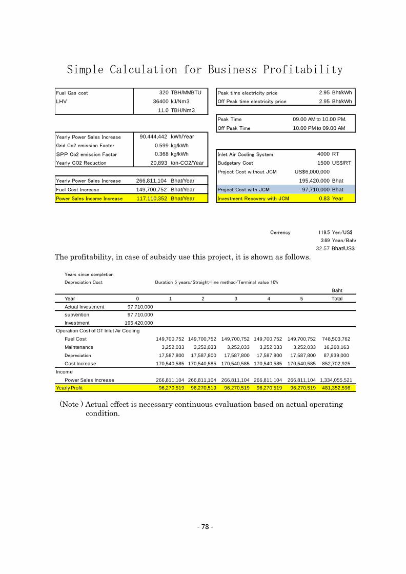
- 78 -
The profitability, in case of subsidy use this project, it is shown as follows.
(Note ) Actual effect is necessary continuous evaluation based on actual operating
condition.
Simple Calculation for Business Profitability
Fual Gas cost 320 TBH/MMBTU Peak time electricity price 2.95 Bht/kWh
LHV 36400 kJ/Nm3 Off Peak time electricity price 2.95 Bht/kWh
11.0 TBH/Nm3
Peak Time 09.00 AM to 10.00 PM.
Off Peak Time 10.00 PM to 09.00 AM
Yearly Power Sales Increase 90,444,442 kWh/Year
Grid Co2 emission Factor 0.599 kg/kWh
SPP Co2 emission Factor 0.368 kg/kWh Inlet Air Cooling System 4000 RT
Yearly CO2 Reduction 20,893 ton-CO2/Year Budgetary Cost 1500 US$/RT
Project Cost without JCM US$6,000,000
Yearly Power Sales Increase 266,811,104 Bhat/Year 195,420,000 Bhat
Fuel Cost Increase 149,700,752 Bhat/Year Project Cost with JCM 97,710,000 Bhat
Power Sales Income Increase 117,110,352 Bhat/Year Investment Recovery with JCM 0.83 Year
Cerrency 119.5 Yen/US$
3.69 Yean/Bahr
32.57 Bhat/US$
Years since completion
Depreciation Cost Duration 5 years/Straight-line method/Terminal value 10%
Baht
Year 0 1 2 3 4 5 Total
Actual Investment 97,710,000
subvention 97,710,000
Investment 195,420,000
Operation Cost of GT Inlet Air Cooling
Fuel Cost 149,700,752 149,700,752 149,700,752 149,700,752 149,700,752 748,503,762
Maintenance 3,252,033 3,252,033 3,252,033 3,252,033 3,252,033 16,260,163
Depreciation 17,587,800 17,587,800 17,587,800 17,587,800 17,587,800 87,939,000
Cost Increase 170,540,585 170,540,585 170,540,585 170,540,585 170,540,585 852,702,925
Income
Power Sales Increase 266,811,104 266,811,104 266,811,104 266,811,104 266,811,104 1,334,055,521
Yearly Profit 96,270,519 96,270,519 96,270,519 96,270,519 96,270,519 481,352,596

Feasibility Study Reportof
Inlet Air Cooling System Studyfor
SPP Power Plant
Mechanism of Gas Turbine Inlet Air Cooling System
Gas Turbine Power Output will be determined by Inlet Air Temperature.
Power Output Increase
By Gas Turbine Characteristic
Gas Turbine Power Output Characteristic (FT-8)
20000
22000
24000
26000
28000
0 10 20 30 40
Inlet Air Temperature (℃)
Pow
er
Outp
ut
(kW
)
Power Output (kW)
Operating Point of Without Inlet Air Cooling
Operating Point of Gas Turbine Inlet Air Cooling
Temperature Decrease
Po
wer
Incr
ease
Gas Turbine Inlet Air System
Cool down inlet air temperature by chiller
If inlet air temperature rise ,Gas Turbine Power Output will decrease
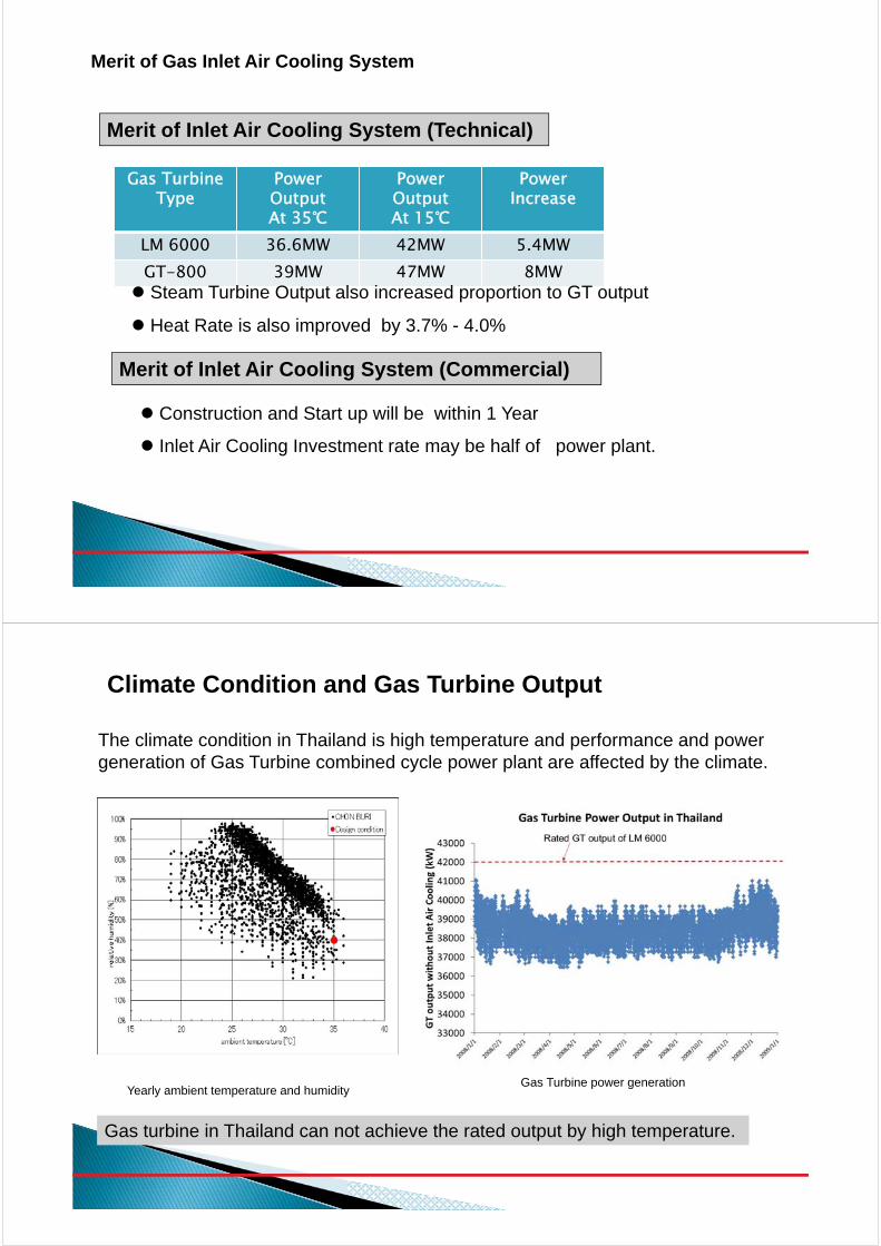
Merit of Gas Inlet Air Cooling System
Merit of Inlet Air Cooling System (Technical)
Gas Turbine Type
Power OutputAt 35℃
Power OutputAt 15℃
PowerIncrease
LM 6000 36.6MW 42MW 5.4MWGT-800 39MW 47MW 8MW Steam Turbine Output also increased proportion to GT output
Heat Rate is also improved by 3.7% - 4.0%
Merit of Inlet Air Cooling System (Commercial)
Construction and Start up will be within 1 Year
Inlet Air Cooling Investment rate may be half of power plant.
Climate Condition and Gas Turbine Output
The climate condition in Thailand is high temperature and performance and power generation of Gas Turbine combined cycle power plant are affected by the climate.
Yearly ambient temperature and humidityGas Turbine power generation
Gas turbine in Thailand can not achieve the rated output by high temperature.

SPP in Thai Land
There are many SPP using LM6000 & GT-800 in Thailand which capacity is 110MW.
G G
Gas Turbine
HRSG
PowerSupply
G
Fuel
HRSG
Fuel
SteamSupply
Gas Turbine
Steam Turbine
LM6000 Performance Characteristic
34,000kW
40,500kW
6500kW /GT power increase can be expected. (40,500kW – 34,000kW)
19% Power Increase
Heat Rate at 30℃ 9,500kJ/kWh
Heat Rate at 15℃ 9,050kJ/kW 4.5% Efficiency Increase
Power Generation Heat Rate

GT-800 Performance Characteristic
35℃15℃
39MW
47MW
35℃15℃
10.09MJ/kWh
9.6MJ/kWh
8000kW /GT power increase can be expected
20% Increase
Heat rate will be improved
from 10.09MJ/kW to 9.6MJ/kW (around 4.8%)
Power Generation Heat Rate
Steam Turbine Characteristic (GT-800)
Steam turbine output 14MW at steam flow 50t/h
Steam turbine output 30MW at Steam flow 100t/h

Yearly Power Increase
LM 6000 GT-800
The power generation increase of combined cycle power plant were calculated based on the ambient temperature data of Thailand.
Cooling Load for GT x 2 + ST x 1 combined cycle
GT-800LM 6000
The cooling load of inlet air cooling system is calculated.
The chiller capacity of each gas turbine type can be 4000RT .

Chiller for Gas Turbine Inlet Air Cooling System
Size 32m x Width 9.2m x 10mH
ChillerLevel
Cooling tower Level
Chiller for Gas Turbine Inlet Air Cooling System
Inlet Air Cooling
System 3D Image

Effectiveness of CO2 Reduction for GT inlet air cooling for SPP
CO2 emission of power generation
CO2 reduction by low CO2 emission power increase of SPP.
EGAT Grid Power CO2 emission factor
0.5594kg-CO2/kWh
Effectiveness of CO2 Reduction for GT inlet air cooling in SPP
System Power Sales Increase CO2 ReductionLM 6000GT x 2 + ST x 1Combined Cycle
112,538,090 kWh/Year 39,922 ton-CO2/ Year
GT-800GT x 2 +ST x 1Combined Cycle
90,444,442 kWh/Year 27,370ton-CO2/Year

Investment and Profit Analysis of GT Inlet Air Cooling System (GT-800 Case)
Fual Gas 320 TBH/MMBTU Peak time electricity price 2.95 Bht/kWh
LHV 36400 kJ/Nm3 Off Peak time electricity price 2.95 Bht/kWh
11.0 TBH/Nm3
Peak Time 09.00 AM to 10.00 PM.
Off Peak Time 10.00 PM to 09.00 AM
Yearly Power Sales Increase 90,444,442 kWh/Year
Grid Co2 emission Factor 0.599 kg/kWh
SPP Co2 emission Factor 0.368 kg/kWh Inlet Air Cooling System 4000 RT
Yearly CO2 Reduction 20,893 ton-CO2/Year Budgetary Cost 1500 US$/RT
Project Cost without JCM US$6,000,000
Yearly Power Sales Increase 266,811,104 Bhat/Year 195,420,000 Bhat
Fuel Cost Increase 149,700,752 Bhat/Year Project Cost with JCM 97,710,000 Bhat
Power Sales Income Increase 117,110,352 Bhat/Year Investment Recovery with JCM 0.83 Year
Investment Recovery will be 0.83 year
with JCM Support
Operation of GT Inlet Air Cooling System (GT-800 Case)
Baht
Year 0 1 2 3 4 5 Total
Investment 97,710,000
Operation Cost of GT Inlet Air Cooling
Fuel Cost 149,700,752 149,700,752 149,700,752 149,700,752 149,700,752 748,503,762
Maintenance 3,252,033 3,252,033 3,252,033 3,252,033 3,252,033 16,260,163
Depreciation 17,587,800 17,587,800 17,587,800 17,587,800 17,587,800 87,939,000
Cost Increase 170,540,585 170,540,585 170,540,585 170,540,585 170,540,585 852,702,925
Income
Power Sales Increase 266,811,104 266,811,104 266,811,104 266,811,104 266,811,104 1,334,055,521
Yearly Profit 96,270,519 96,270,519 96,270,519 96,270,519 96,270,519 481,352,596

Organization for project execution
Consortium Leader(Japanese Company)
SPPCompany
Centrifugal ChillerInlet air coolerDetail Design Control System
International Consortium
Local Company Site Construction Work
Piping, Electrical, Instrumentation
Order to Supplier
Gas Turbine Modification To install air cooler
MRV Consultant(CO2 Reduction Monitoring)
Japanese Government 50% Project Support
Project Schedule to much the fiscal year
2015 2016No Items May June July Aug Sep Oct Nov Dec Jan Feb Mar
1 Detail DesignEquipment PipingElectrical & Instrumentation
2 ManufacturingCentrifugal ChillerInlet Air CoolerPumpsCooling TowerPiping PartsStructurePower Receiving System
3 Site Construction WorkCivil WorkPiping WorkCooling TowerElectcal EquipmentElectrical WorkChiller Installation
4 CommissioningPower Receiving SystemChiller System
5 Operation Start
Construction will be completed within year.

Expected Schedule of JCM application
50% Payment Call for Application
ApplicationClose
Notice toproceed
Site CheckBy Japanese Government
Site CheckBy Japanese Government
Preparation Evaluation Project Execution
20/April 19/May June November March April
2-3 year project
CO2 Reduction report must be submitted to Japanese Government
Japanese company (MHI) will handle to submit the report.
MRV (Measurement , Reporting and Verification)
Installation of Air Cooler

How to Install Air Cooler
Side View
Air Cooler
Air Filter Unit
For Gas Turbine
Gas Turbine
Air Cooler
Demister
Inlet Air 33℃Supply Air 15℃
Weather Louver
Pre-filter
Air Cooling Coil
Demister
Chiller Module