Embed Size (px)
Citation preview

63www.conesys.com [email protected]
5015 S III
– –
MIL-DTL-5015 /AS50151Features and ApplicationSeries III
Features and Application
The threaded coupling, environmentally sealed MIL-DTL-5015 Series III connector with rear-removable crimp contacts was developed to replace the earlier solder type. This redesigned connector is intermateable and intermountable with the MIL-DTL-5015 Series I solder type (MS310*) as well as the MIL-DTL- 83723 Series II (USAF) crimp type and MIL-DTL-5015 Series II Front Release (MS340*). Thus, it provides for a minimum effort and high economy upgrade for existing applications.
These connectors are recommended for a wide range of applications, from commercial/industrial and mass transportation systems to the most stringent high reliability defense and aerospace requirements.
This family of connectors is offered in four receptacle mounting configurations. They include two square flange receptacles, both wall and box mounting; cable connecting receptacles; and jam nut receptacles which incorporate “O” ring seals, designed for rear panel “D” hole mounting.
Two plug styles are offered - standard plug with free rotating coupling nut with safety wire holes, and a self-lock-ing, anti-decoupling plug, which eliminates the need for safety wiring.
Eighty-eight insert arrangements per MIL-STD-1651 are tooled and qualified to MIL-DTL-5015, utilizing 1 to 85 contacts. Contacts come in sizes 16, 12, 8, 4 and 0, terminating wire sizes from 20 gauge to 0 gauge.
These connectors are available in wide range of shell materials and finishes. Aluminum shells are offered in both electroless nickel and olive drab cadmium to both commercial and MS callouts. Other finishes such as anodic and zinc cobalt are available upon request to commercial callouts only. In addition, we offer passivated stainless steel shells with both standard and firewall-rated inserts, and carbon steel shells with firewall inserts.
Lockwiring Eliminated – Self-locking plug eliminates the need for lockwiring.
Universal I/R Tool – A single, expendable plastic tool is used for both insertion and removal of contacts.
Insert Polarization – Alternate insert clocking positions aid in mating of adjacent connectors having identical insert arrangement.
Closed-Entry Socket Insert – Hard dielectric socket face has lead-in chamfers for positive alignment of pins (even partially bent within pre-established limits) with sockets.
Interfacial Pin Insert Seal – Raised moisture barriers around each pin, which mate into lead-in chamfers of hard face socket insert, provide individual contact sealing. Interfacial seal is never touched by service tools.
Elastomer Wire Sealing Grommet – Sealing over a wide range of wire diameters is assured by a triple wire seal in each cavity at the rear of the connector.
Superior Contact Stability – Rear release crimp contact system features a stamped beryllium-copper retaining clip captivated by molded-in shoulders of each contact cavity in the insulator. A rear-inserted M81969 plastic tool expands the tines beyond the shoulder, releasing the contact.

64www.conesys.com [email protected]
5015 S III
– –
MIL-DTL-5015 /AS50151Performance Specifications
MS345*/AE55*
Performance Specifications
Operating Temperature RangeClasses KS and LS: -55°C to +200°C (-67°F to +392°F)Classes KT and W: -55°C to +175°C (-67°F to +347°F)Class L: -55°C to +200°C (-67°F to +392°F)Class A*: -55°C to +200°C (-67°F to +392°F)
Material and Finish Data (Class)KT – carbon steel shell, olive drab cadmium, firewallKS – stainless steel shell, passivated, firewallL – aluminum shell, electroless nickel finishLS – stainless steel shell, passivatedW – aluminum shell, olive drab cadmium over nickel baseA* – aluminum shell, black anodized finish
Corrosion ResistanceClasses KS and LS withstand 1,000-hour salt spray.Class KT withstands 96-hour salt spray.Class L withstands 96-hour salt spray.Class W withstands 1,000-hour salt spray.
Environmental SealWired, mated connectors with specified accessories attached, shall meet the altitude-immersion test specified in MIL-DTL-5015.
DurabilityMinimum of 100 mating cycles
Voltage Rating
Shock and Vibration RequirementsWired, mated connectors shall not be damaged, coupling ring shall not loosen, and there shall be no interruption of electrical continuity longer than 10 microseconds when subjected to the following:
ShockMated connectors withstand a pulse of approximate half sine wave of 50 G magnitude with duration of 11 milliseconds applied in three axes per MIL-STD-1344, method 2004, test condition A.
VibrationMated connectors withstand the following vibration levels:• Random vibration per MIL-STD-1344, method 2005,
and test condition VI, letter J.
Shell-to-Shell ConductivityMaximum potential drop shall not exceed:• Class W = 5 millivolts• All other classes (except A*) = 50 millivolts
Fluid ResistanceConnectors resist specified immersions in MIL-PRF-7808 (lubricating oil), MIL-PRF-23699 (lubricating oil), MIL-PRF-5606 (hydraulic fluid), M2-V Chevron oil, Coolanol 25, MIL-DTL-83133 (turbine fuel JP-8), MIL-DTL-5624 (turbine fuels JP-4 and JP-5), SAE-AMS1424 Type I (defrosting fluid), and other solvents and cleaning agents.
* Not MS approved, available to Aero-Electric part number only.**To be used by designer only as a guide.
ServiceRating
Maximum Operating Voltage** Test Voltage Test Voltage Test Voltage Test Voltage(Sea Level) Sea Level 50,000 Ft 70,000 Ft. 110,000 Ft.
AC (RMS) DC V RMS V RMS V RMS V RMS
Inst. 200 250 1000 400 260 200
A 500 700 2000 600 360 200
D 900 1250 2800 675 400 200
E 1250 1750 3500 750 440 200
B 1750 2450 4500 825 480 200
C 3000 4200 7000 975 560 200

65www.conesys.com [email protected]
5015 S III
– –
MIL-DTL-5015 Series III /AS50151Part Number DevelopmentRear Release
Military and Aero-Electric Part Number Development
Note 1: Each connector is furnished with contacts unless ordered less contacts (L/C) as follows: One spare contact for inserts requiring 2 to 26 of each contact and two spares for inserts with 27 or more of each size, and a minimum of one sealing plug up to 15% of the number contacts. No spares or seal plugs are provided with one contact layouts. No spares or seal plugs for contact sizes 0 and 4 are provided. For contact size 8, no contact spares are provided, but seal plugs are included. In addition, one insertion/removal tool of each size is included.
Note 2: KS and KT firewall classes are only available to Military part numbers for shell types MS3450, MS3456 and MS3459. KS and KT classes are available to Aero callouts for AE551 and 554, but not for AE552 (box mount receptacle).
Note 3: Proper part number marking has no “0” in front of single digit (numeric) shell size (8S) and no “0” in front of single digit layout. Examples: J MS3450W8S-1S and J MS3450W24-2PW. Please note that J or JAN marking is required immediately in front of MS part number.
Mil. Prefix MS34 50 L 14S - 5 P XAero Prefix AE5 50 L 14S - 5 P X -340Shell Type
50 = Wall mount receptacle
51 = Cable connecting receptacle
52 = Box mount receptacle
54 = Jam nut receptacle
56 = Straight plug
59 = Self-locking plug
Class (Material and Finish)A = Aluminum shell, black anodized finish (Aero part number only)
KS = Stainless steel shell, passivated, firewall (n/a in MS3451, MS3452, MS3454)
KT = Carbon steel shell, cadmium finish, firewall (n/a in MS3451, MS3452, MS3454)
LS = Stainless steel shell, passivated
L = Aluminum shell, electroless nickel finish
W = Aluminum shell, olive drab cadmium over electroless nickel base
Shell Size8S, 10S, 10SL, 12, 12S, 14, 14S, 16, 16S, 18, 20, 22, 24, 28, 32, 36 or 40
Insert ArrangementSee pages 82 thru 87
Contact StyleP = Pin
S = Socket
A = Pin connector less pins (with intent to use non-std contact)
B = Socket connector less sockets (with intent to use non-std contacts)
PolarizationN = Normal (not included in part number)
W, X, Y or Z = Alternate insert polarizations (see pages 77 thu 81 for position availability)
Modification (applies to Aero part numbers only)01 = Less contacts (is not marked on the part)
340 = Connector kitted with M85049/31-XXX E-nut
341 = Connector kitted with M85049/52-1-XXX straight clamp
342 = Connector kitted with M85049/51-1-XXX right angle clamp
Consult factory for other modifications

66www.conesys.com [email protected]
5015 S III
– –
MS3450 per AS34501Wall Mount Receptacle
AE550
Threaded Coupling, Crimp Removable, Rear Release
Note 1: L max is same as L max for AE551 on next page.
Note 2: Maximum grommet O.D. is same as Ø E max for AE551 on next page.
BLUE COLOR BANDS
J ACCESSORY THREAD
G
F
A MATING THREAD
D BPOLARIZING KEY
4x � H HOLES
3 ACCESSORY TEETH
LMAX
MIN FULL THREAD.290(7.37) FOR 8S-24.467(11.86) FOR 28-40
GROMMETEXTENSION .190(4.83)
.130(3.30)FOR 16 AND 12 CONTACTS
.340(8.64)
.130(3.30)FOR 8,4, AND 0 CONTACTS
Page 65 Completed Part NumberPage 75 Contacts, Sealing Plugs and ToolsPages 82–87 Insert ArrangementsPage 64 Performance SpecificationsPages 77–81 Insert Availability and Contact InformationPage 77 Polarization
ShellSize
A B D F G Ø H J Mating Classes L, LS, W Classes KS, KT AccessoryThread +.031 +.79 +.010 +.25 +.010 +.25 Thread
Class 2A ±.015 ±.38 -.000 -.00 (TP) ±.031 ±.79 -.005 -.13 -.005 -.13 Class 2Ainch mm inch mm inch mm inch mm inch mm inch mm
8S 1/2-28 UNEF .083 2.11 .562 14.27 .594 15.09 .875 22.23 .120 3.05 .150 3.81 1/2-20UNF10S 5/8-24 UNEF .083 2.11 .562 14.27 .719 18.26 1.000 25.40 .120 3.05 .150 3.81 5/8-24UNEF
10SL 5/8-24 UNEF .083 2.11 .562 14.27 .719 18.26 1.000 25.40 .120 3.05 .150 3.81 5/8-24UNEF12 3/4-20 UNEF .083 2.11 .750 19.05 .812 20.62 1.094 27.79 .120 3.05 .150 3.81 3/4-20UNEF
12S 3/4-20 UNEF .083 2.11 .562 14.27 .812 20.62 1.094 27.79 .120 3.05 .150 3.81 3/4-20UNEF14 7/8-20 UNEF .083 2.11 .750 19.05 .906 23.01 1.188 30.18 .120 3.05 .150 3.81 7/8-20UNEF
14S 7/8-20 UNEF .083 2.11 .562 14.27 .906 23.01 1.188 30.18 .120 3.05 .150 3.81 7/8-20UNEF16 1-20 UNEF .083 2.11 .750 19.05 .969 24.61 1.281 32.54 .120 3.05 .150 3.81 1-20UNEF
16S 1-20 UNEF .083 2.11 .562 14.27 .969 24.61 1.281 32.54 .120 3.05 .150 3.81 1-20UNEF18 1 1/8-18 UNEF .125 3.18 .750 19.05 1.062 26.97 1.375 34.93 .120 3.05 .177 4.50 1-1/16-18UNEF20 1 1/4-18 UNEF .125 3.18 .750 19.05 1.156 29.36 1.500 38.10 .120 3.05 .177 4.50 1-3/16-18UNEF22 1 3/8-18 UNEF .125 3.18 .750 19.05 1.250 31.75 1.625 41.28 .120 3.05 .177 4.50 1-5/16-18UNEF24 1 1/2-18 UNEF .125 3.18 .812 20.62 1.375 34.93 1.750 44.45 .147 3.73 .177 4.50 1-7/16-18UNEF28 1 3/4-18 UNS .125 3.18 .812 20.62 1.562 39.67 2.000 50.80 .147 3.73 .177 4.50 1-3/4-18UNS32 2-18 UNS .125 3.18 .875 22.23 1.750 44.45 2.250 57.15 .173 4.39 .209 5.31 2-18UNS36 2 1/4-16 UN .125 3.18 .875 22.23 1.938 49.23 2.500 63.50 .173 4.39 .209 5.31 2-1/4-16UN40 2 1/2-16 UN .125 3.18 .875 22.23 2.188 55.58 2.750 69.85 .173 4.39 .209 5.31 2-1/2-16UN

67www.conesys.com [email protected]
5015 S III
– –
MS3451 per AS34511Cable Connecting ReceptacleAE551
Threaded Coupling, Crimp Removable, Rear Release
� S� EMAX
GROMMET
BLUE COLOR BANDS V ACCESSORY THREAD
A MATING THREAD
M
L MAXR
ACROSS FLATS
3 ACCESSORY TEETH
MIN FULL THREAD.290(7.37) FOR 8S-24.467(11.86) FOR 28-40
.083±.015(2.11±.38) FOR 8S-16S
.125±.015(3.18±.38) FOR 18-40
GROMMETEXTENSION .190(4.83)
.130(3.30)FOR 16 AND 12 CONTACTS
.340(8.64)
.130(3.30)FOR 8,4, AND 0 CONTACTS
POLARIZING KEY
ShellSize
A Ø E L MAX M R Ø S V Mating Thread 16 & 12 8, 4 & 0 +.031 +.79 Accessory Thread
Class 2A Maximum Contacts Contacts -.000 -.00 ±.031 ±.79 Class 2Ainch mm inch mm inch mm inch mm inch mm inch mm
8S 1/2-28 UNEF .305 7.75 2.031 51.59 – – .562 14.27 .504/.496 12.80/12.60 .729 18.52 1/2-20UNF
10S 5/8-24 UNEF .405 10.29 2.031 51.59 – – .562 14.27 .629/.621 15.98/15.77 .854 21.69 5/8-24UNEF
10SL 5/8-24 UNEF .405 10.29 2.031 51.59 – – .562 14.27 .629/.621 15.98/15.77 .854 21.69 5/8-24UNEF
12 3/4-20 UNEF .549 13.94 2.125 53.98 – – .750 19.05 .754/.746 19.15/18.95 .974 24.74 3/4-20UNEF
12S 3/4-20 UNEF .549 13.94 2.031 51.59 – – .562 14.27 .754/.746 19.15/18.95 .974 24.74 3/4-20UNEF
14 7/8-20 UNEF .665 16.89 2.125 53.98 – – .750 19.05 .879/.871 22.33/22.12 1.099 27.91 7/8-20UNEF
14S 7/8-20 UNEF .665 16.89 2.031 51.59 – – .562 14.27 .879/.871 22.33/22.12 1.099 27.91 7/8-20UNEF
16 1-20 UNEF .790 20.07 2.125 53.98 2.500 63.50 .750 19.05 1.005/.996 25.53/25.30 1.224 31.09 1-20UNEF
16S 1-20 UNEF .790 20.07 2.031 51.59 – – .562 14.27 1.005/.996 25.53/25.30 1.224 31.09 1-20UNEF
18 1 1/8-18 UNEF .869 22.07 2.125 53.98 2.500 63.50 .750 19.05 1.131/1.121 28.73/28.47 1.349 34.26 1-1/16-18UNEF
20 1 1/4-18 UNEF .994 25.25 2.125 53.98 2.500 63.50 .750 19.05 1.256/1.246 31.90/31.65 1.474 37.44 1-3/16-18UNEF
22 1 3/8-18 UNEF 1.119 28.42 2.125 53.98 2.500 63.50 .750 19.05 1.381/1.371 35.08/34.82 1.599 40.61 1-5/16-18UNEF
24 1 1/2-18 UNEF 1.244 31.60 2.125 53.98 2.500 63.50 .812 20.62 1.506/1.496 38.25/38.00 1.715 43.56 1-7/16 -18UNEF
28 1 3/4-18 UNS 1.465 37.21 2.125 53.98 2.500 63.50 .812 20.62 1.756/1.746 44.60/44.35 1.974 50.14 1-3/4-18UNS
32 2-18 UNS 1.715 43.56 2.125 53.98 2.500 63.50 .875 22.23 2.007/1.996 50.98/50.70 2.224 56.49 2-18UNS
36 2 1/4-16 UN 1.930 49.02 2.125 53.98 2.500 63.50 .875 22.23 2.257/2.246 57.33/57.05 2.474 62.84 2-1/4-16UN
40 2 1/2-16 UN 2.145 54.48 2.125 53.98 2.500 63.50 .875 22.23 2.511/2.496 63.78/63.40 2.724 69.19 2-1/2-16UN
Page 65 Completed Part NumberPage 75 Contacts, Sealing Plugs and ToolsPages 82–87 Insert ArrangementsPage 64 Performance SpecificationsPages 77–81 Insert Availability and Contact InformationPage 77 Polarization

68www.conesys.com [email protected]
5015 S III
– –
MS3452 per AS34521 Box Mount Receptacle
AE552
Threaded Coupling, Crimp Removable, Rear Release
S
R
A MATING THREAD
M
LMAX
� GG
4x � T HOLES
.083±.015(2.11±.38) FOR 8S-16S
.125±.015(3.18±.38) FOR 18-40
BLUE COLOR BAND
POLARIZING KEY
Page 65 Completed Part NumberPage 75 Contacts, Sealing Plugs and ToolsPages 82–87 Insert ArrangementsPage 64 Performance SpecificationsPages 77–81 Insert Availability and Contact InformationPage 77 Polarization
Note 1: The insulation material shall be above, flush with, or no more than .015 inches (.38 mm) below the metal shell.
ShellSize
A Ø GG L MAX M R S Ø TMating Thread 16 & 12 8, 4 & 0 +.031 +.79 +.010 +.25
Class 2A ±.016 ±.41 Contacts Contacts -.000 -.00 (TP) ±.031 ±.79 -.005 -.13inch mm inch mm inch mm inch mm inch mm inch mm inch mm
8S 1/2-28 UNEF .500 12.70 1.662 42.21 – – .562 14.27 .594 15.09 .875 22.23 .120 3.05
10S 5/8-24 UNEF .625 15.88 1.662 42.21 – – .562 14.27 .719 18.26 1.000 25.40 .120 3.05
10SL 5/8-24 UNEF .625 15.88 1.662 42.21 – – .562 14.27 .719 18.26 1.000 25.40 .120 3.05
12 3/4-20 UNEF .750 19.05 1.662 42.21 – – .750 19.05 .812 20.62 1.094 27.79 .120 3.05
12S 3/4-20 UNEF .750 19.05 1.662 42.21 – – .562 14.27 .812 20.62 1.094 27.79 .120 3.05
14 7/8-20 UNEF .875 22.23 1.662 42.21 – – .750 19.05 .906 23.01 1.188 30.18 .120 3.05
14S 7/8-20 UNEF .875 22.23 1.662 42.21 – – .562 14.27 .906 23.01 1.188 30.18 .120 3.05
16 1-20 UNEF 1.000 25.40 1.662 42.21 1.937 49.20 .750 19.05 .969 24.61 1.281 32.54 .120 3.05
16S 1-20 UNEF 1.000 25.40 1.662 42.21 – – .562 14.27 .969 24.61 1.281 32.54 .120 3.05
18 1 1/8-18 UNEF 1.062 26.97 1.662 42.21 1.937 49.20 .750 19.05 1.062 26.97 1.375 34.93 .120 3.05
20 1 1/4-18 UNEF 1.187 30.15 1.662 42.21 1.937 49.20 .750 19.05 1.156 29.36 1.500 38.10 .120 3.05
22 1 3/8-18 UNEF 1.312 33.32 1.662 42.21 1.937 49.20 .750 19.05 1.250 31.75 1.625 41.28 .120 3.05
24 1 1/2-18 UNEF 1.437 36.50 1.662 42.21 1.937 49.20 .812 20.62 1.375 34.93 1.750 44.45 .147 3.73
28 1 3/4-18 UNS 1.750 44.45 1.662 42.21 1.937 49.20 .812 20.62 1.562 39.67 2.000 50.80 .147 3.73
32 2-18 UNS 2.000 50.80 1.662 42.21 1.937 49.20 .875 22.23 1.750 44.45 2.250 57.15 .173 4.39
36 2 1/4-16 UN 2.250 57.15 1.662 42.21 1.937 49.20 .875 22.23 1.938 49.23 2.500 63.50 .173 4.39
40 2 1/2-16 UN 2.500 63.50 1.662 42.21 1.937 49.20 .875 22.23 2.188 55.58 2.750 69.85 .173 4.39
69www.conesys.com [email protected]
5015 S III
– –
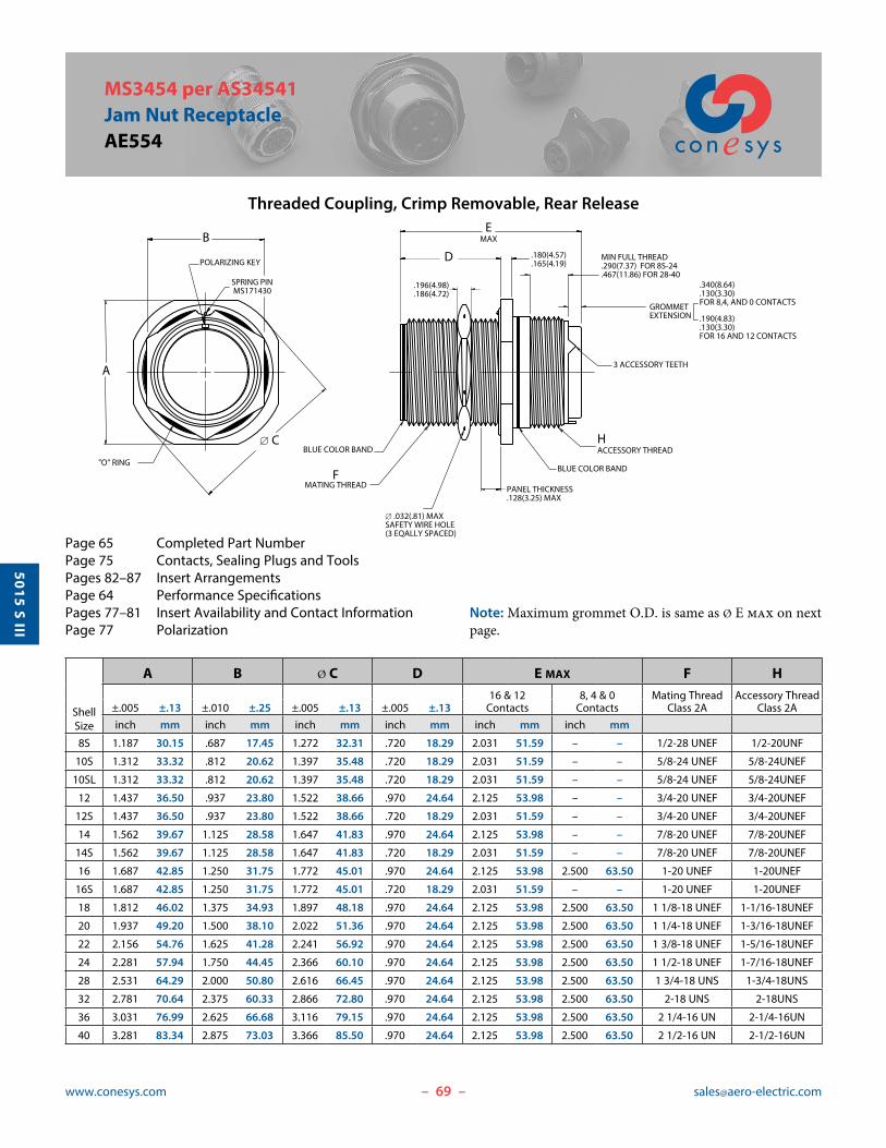
MS3454 per AS34541Jam Nut ReceptacleAE554
Threaded Coupling, Crimp Removable, Rear Release
MIN FULL THREAD.290(7.37) FOR 8S-24.467(11.86) FOR 28-40
BLUE COLOR BAND
BLUE COLOR BAND
D .180(4.57).165(4.19)
FMATING THREAD
HACCESSORY THREAD
� .032(.81) MAXSAFETY WIRE HOLE(3 EQALLY SPACED)
"O" RING
A
B
� C
SPRING PIN MS171430
PANEL THICKNESS.128(3.25) MAX
.196(4.98)
.186(4.72)
EMAX
3 ACCESSORY TEETH
GROMMETEXTENSION .190(4.83)
.130(3.30)FOR 16 AND 12 CONTACTS
.340(8.64)
.130(3.30)FOR 8,4, AND 0 CONTACTS
POLARIZING KEY
Page 65 Completed Part NumberPage 75 Contacts, Sealing Plugs and ToolsPages 82–87 Insert ArrangementsPage 64 Performance SpecificationsPages 77–81 Insert Availability and Contact InformationPage 77 Polarization
Note: Maximum grommet O.D. is same as Ø E max on next page.
ShellSize
A B Ø C D E MAX F H16 & 12 8, 4 & 0 Mating Thread Accessory Thread
±.005 ±.13 ±.010 ±.25 ±.005 ±.13 ±.005 ±.13 Contacts Contacts Class 2A Class 2Ainch mm inch mm inch mm inch mm inch mm inch mm
8S 1.187 30.15 .687 17.45 1.272 32.31 .720 18.29 2.031 51.59 – – 1/2-28 UNEF 1/2-20UNF
10S 1.312 33.32 .812 20.62 1.397 35.48 .720 18.29 2.031 51.59 – – 5/8-24 UNEF 5/8-24UNEF
10SL 1.312 33.32 .812 20.62 1.397 35.48 .720 18.29 2.031 51.59 – – 5/8-24 UNEF 5/8-24UNEF
12 1.437 36.50 .937 23.80 1.522 38.66 .970 24.64 2.125 53.98 – – 3/4-20 UNEF 3/4-20UNEF
12S 1.437 36.50 .937 23.80 1.522 38.66 .720 18.29 2.031 51.59 – – 3/4-20 UNEF 3/4-20UNEF
14 1.562 39.67 1.125 28.58 1.647 41.83 .970 24.64 2.125 53.98 – – 7/8-20 UNEF 7/8-20UNEF
14S 1.562 39.67 1.125 28.58 1.647 41.83 .720 18.29 2.031 51.59 – – 7/8-20 UNEF 7/8-20UNEF
16 1.687 42.85 1.250 31.75 1.772 45.01 .970 24.64 2.125 53.98 2.500 63.50 1-20 UNEF 1-20UNEF
16S 1.687 42.85 1.250 31.75 1.772 45.01 .720 18.29 2.031 51.59 – – 1-20 UNEF 1-20UNEF
18 1.812 46.02 1.375 34.93 1.897 48.18 .970 24.64 2.125 53.98 2.500 63.50 1 1/8-18 UNEF 1-1/16-18UNEF
20 1.937 49.20 1.500 38.10 2.022 51.36 .970 24.64 2.125 53.98 2.500 63.50 1 1/4-18 UNEF 1-3/16-18UNEF
22 2.156 54.76 1.625 41.28 2.241 56.92 .970 24.64 2.125 53.98 2.500 63.50 1 3/8-18 UNEF 1-5/16-18UNEF
24 2.281 57.94 1.750 44.45 2.366 60.10 .970 24.64 2.125 53.98 2.500 63.50 1 1/2-18 UNEF 1-7/16-18UNEF
28 2.531 64.29 2.000 50.80 2.616 66.45 .970 24.64 2.125 53.98 2.500 63.50 1 3/4-18 UNS 1-3/4-18UNS
32 2.781 70.64 2.375 60.33 2.866 72.80 .970 24.64 2.125 53.98 2.500 63.50 2-18 UNS 2-18UNS
36 3.031 76.99 2.625 66.68 3.116 79.15 .970 24.64 2.125 53.98 2.500 63.50 2 1/4-16 UN 2-1/4-16UN
40 3.281 83.34 2.875 73.03 3.366 85.50 .970 24.64 2.125 53.98 2.500 63.50 2 1/2-16 UN 2-1/2-16UN

70www.conesys.com [email protected]
5015 S III
– –
MS3456 per AS34561 Straight Plug
AE556
Threaded Coupling, Crimp Removable, Rear Release
Page 65 Completed Part NumberPage 75 Contacts, Sealing Plugs and ToolsPages 82–87 Insert ArrangementsPage 64 Performance SpecificationsPages 77–81 Insert Availability and Contact InformationPage 77 Polarization
MIN FULL THREAD.290(7.37) FOR 8S-24.467(11.86) FOR 28-40
GROMMETEXTENSION .190(4.83)
.130(3.30)FOR 16 AND 12 CONTACTS
.340(8.64)
.130(3.30)FOR 8,4, AND 0 CONTACTS
� AMAX
C MATING THREAD
BLUE COLOR BAND
H MAX
3x � .035(.89) SAFETYWIRE HOLESEQUALLY SPACED
F ACCESSORY THREAD
3 TEETHEQUALLY SPACED
� EMAXGROMMET
� B
POLARIZING KEYWAY
ShellSize
Ø A Ø B C Ø E F H MAX
Mating Thread Accessory Thread 16 & 12 8, 4 & 0Maximum ±.005 ±.13 Class 2B Maximum Class 2A Contacts Contacts
inch mm inch mm inch mm inch mm inch mm
8S .844 21.44 .360 9.14 1/2-28 UNEF .305 7.75 1/2-20UNF 2.031 51.59 – –
10S .969 24.61 .435 11.05 5/8-24 UNEF .405 10.29 5/8-24UNEF 2.031 51.59 – –
10SL .969 24.61 .443* 11.25* 5/8-24 UNEF .405 10.29 5/8-24UNEF 2.031 51.59 – –
12 1.062 26.97 .550 13.97 3/4-20 UNEF .549 13.94 3/4-20UNEF 2.125 53.98 – –
12S 1.062 26.97 .550 13.97 3/4-20 UNEF .549 13.94 3/4-20UNEF 2.031 51.59 – –
14 1.156 29.36 .670 17.02 7/8-20 UNEF .665 16.89 7/8-20UNEF 2.125 53.98 – –
14S 1.156 29.36 .670 17.02 7/8-20 UNEF .665 16.89 7/8-20UNEF 2.031 51.59 – –
16 1.250 31.75 .800 20.32 1-20 UNEF .790 20.07 1-20UNEF 2.125 53.98 2.500 63.50
16S 1.250 31.75 .800 20.32 1-20 UNEF .790 20.07 1-20UNEF 2.031 51.59 – –
18 1.344 34.14 .925 23.50 1 1/8-18 UNEF .869 22.07 1-1/16-18UNEF 2.125 53.98 2.500 63.50
20 1.469 37.31 1.045 26.54 1 1/4-18 UNEF .994 25.25 1-3/16-18UNEF 2.125 53.98 2.500 63.50
22 1.594 40.49 1.170 29.72 1 3/8-18 UNEF 1.119 28.42 1-5/16-18UNEF 2.125 53.98 2.500 63.50
24 1.719 43.66 1.295 32.89 1 1/2-18 UNEF 1.244 31.60 1-7/16-18UNEF 2.125 53.98 2.500 63.50
28 1.969 50.01 1.515 38.48 1 3/4-18 UNS 1.465 37.21 1-3/4-18UNS 2.125 53.98 2.500 63.50
32 2.219 56.36 1.765 44.83 2-18 UNS 1.715 43.56 2-18UNS 2.125 53.98 2.500 63.50
36 2.469 62.71 1.975 50.17 2 1/4-16 UN 1.930 49.02 2-1/4-16UN 2.125 53.98 2.500 63.50
40 2.719 69.06 2.225 56.52 2 1/2-16 UN 2.145 54.48 2-1/2-16UN 2.125 53.98 2.500 63.50
* Tolerance for this dimension is ± .003(.08)

71www.conesys.com [email protected]
5015 S III
– –
MS3459 per AS34591Self-Locking PlugAE559
Threaded Coupling, Crimp Removable, Rear Release
Page 65 Completed Part NumberPage 75 Contacts, Sealing Plugs and ToolsPages 82–87 Insert ArrangementsPage 64 Performance SpecificationsPages 77–81 Insert Availability and Contact InformationPage 77 Polarization
LMAX
� CMAX
B ACCESSORY THREAD
3 ACCESSORY TEETH
BLUE COLOR BAND
MIN FULL THREAD.290(7.37) FOR 8S-24.467(11.86) FOR 28-40
� D� EMAX
GROMMET
GROMMETEXTENSION .190(4.83)
.130(3.30)FOR 16 AND 12 CONTACTS
.340(8.64)
.130(3.30)FOR 8,4, AND 0 CONTACTS
A MATING THREAD
POLARIZING KEYWAY
ShellSize
A B Ø C Ø D Ø E L MAX
Mating Thread Accessory Thread 16 & 12 8, 4 & 0Class 2B Class 2A Maximum ±.005 ±.13 Maximum Contacts Contacts
inch mm inch mm inch mm inch mm inch mm
8S 1/2-28 UNEF 1/2-20UNF .963 24.46 .360 9.14 .305 7.75 2.031 51.59 – –
10S 5/8-24 UNEF 5/8-24UNEF 1.088 27.64 .435 11.05 .405 10.29 2.031 51.59 – –
10SL 5/8-24 UNEF 5/8-24UNEF 1.088 27.64 .443* 11.25* .405 10.29 2.031 51.59 – –
12 3/4-20 UNEF 3/4-20UNEF 1.213 30.81 .550 13.97 .549 13.94 2.125 53.98 – –
12S 3/4-20 UNEF 3/4-20UNEF 1.213 30.81 .550 13.97 .549 13.94 2.031 51.59 – –
14 7/8-20 UNEF 7/8-20UNEF 1.358 34.49 .670 17.02 .665 16.89 2.125 53.98 – –
14S 7/8-20 UNEF 7/8-20UNEF 1.358 34.49 .670 17.02 .665 16.89 2.031 51.59 – –
16 1-20 UNEF 1-20UNEF 1.463 37.16 .800 20.32 .790 20.07 2.125 53.98 2.500 63.50
16S 1-20 UNEF 1-20UNEF 1.463 37.16 .800 20.32 .790 20.07 2.031 51.59 – –
18 1 1/8-18 UNEF 1-1/16-18UNEF 1.588 40.34 .925 23.50 .869 22.07 2.125 53.98 2.500 63.50
20 1 1/4-18 UNEF 1-3/16-18UNEF 1.713 43.51 1.045 26.54 .994 25.25 2.125 53.98 2.500 63.50
22 1 3/8-18 UNEF 1-5/16-18UNEF 1.788 45.42 1.170 29.72 1.119 28.42 2.125 53.98 2.500 63.50
24 1 1/2-18 UNEF 1-7/16-18UNEF 1.963 49.86 1.295 32.89 1.244 31.60 2.125 53.98 2.500 63.50
28 1 3/4-18 UNS 1-3/4-18UNS 2.213 56.21 1.515 38.48 1.465 37.21 2.125 53.98 2.500 63.50
32 2-18 UNS 2-18UNS 2.463 62.56 1.765 44.83 1.715 43.56 2.125 53.98 2.500 63.50
36 2 1/4-16 UN 2-1/4-16UN 2.713 68.91 1.975 50.17 1.930 49.02 2.125 53.98 2.500 63.50
40 2 1/2-16 UN 2-1/2-16UN 2.963 75.26 2.225 56.52 2.145 54.48 2.125 53.98 2.500 63.50
* Tolerance for this dimension is ± .003(.08)

72www.conesys.com [email protected]
5015 S III
– –
MIL-DTL-5015 Series III, Rear ReleaseFlange and Jam Nut Receptacles
Panel Cutouts
Panel Cutouts
A
� C � BE
� D
.100(2.54) DIA.
.095(2.41)
MS3454 (AE554) CUTOUT
Flange and Jam Nut Mounting Dimensions
ShellSize
A Ø B Ø C Ø D EClasses L, LS, W Classes KS, KT
+.010 +.25 +.010 +.25 +.015 +.38(TP) ±.010 ±.25 -.005 -.13 -.005 -.13 -.000 -.00 ±.005 ±.13
inch mm inch mm inch mm inch mm inch mm inch mm
8S .594 15.09 .562 14.27 .120 3.05 .150 3.81 .505 12.83 .323 8.20
10S, 10SL .719 18.26 .688 17.48 .120 3.05 .150 3.81 .630 16.00 .385 9.78
12, 12S .812 20.62 .812 20.62 .120 3.05 .150 3.81 .755 19.18 .448 11.38
14, 14S .906 23.01 .938 23.83 .120 3.05 .150 3.81 .880 22.35 .510 12.95
16, 16S .969 24.61 1.062 26.97 .120 3.05 .150 3.81 1.005 25.53 .573 14.55
18 1.062 26.97 1.188 30.18 .120 3.05 .177 4.50 1.130 28.70 .635 16.13
20 1.156 29.36 1.312 33.32 .120 3.05 .177 4.50 1.255 31.88 .698 17.73
22 1.250 31.75 1.438 36.53 .120 3.05 .177 4.50 1.380 35.05 .760 19.30
24 1.375 34.93 1.562 39.67 .147 3.73 .177 4.50 1.505 38.23 .823 20.90
28 1.562 39.67 1.812 46.02 .147 3.73 .177 4.50 1.755 44.58 .948 24.08
32 1.750 44.45 2.062 52.37 .173 4.39 .209 5.31 2.005 50.93 1.073 27.25
36 1.938 49.23 2.312 58.72 .173 4.39 .209 5.31 2.255 57.28 1.198 30.43
40 2.188 55.58 2.562 65.07 .173 4.39 .209 5.31 2.505 63.63 1.323 33.60

73www.conesys.com [email protected]
5015 S III
– –
MS25042Protective Cover, PLUGAE542
Protective Cover, Plug
MIL. PrefixAero Prefix
MS25042-AE542-
XXXX
XXXX
Shell Size8 THRU 44 (Note: single digit for shell size 8)
Material FinishDA = Aluminum, Hard Black AnodizeD = Aluminum, Cadmium Olive DrabL = Aluminum, Electroless Nickel PlateLS = Stainless Steel, PassivatedKT = Carbon Steel, Cadmium Olive Drab
BN = Aluminum, Black Nickel Plate
BZ = Bronze
SHELLSIZE
Coupling Shell Size
A ThreadClass 2A
B Max.
ØCMax.
ØD+.010-.005
E±1
Link
F.016
ØG.016
HMin.
LMax.
8 8S .500-28 UNEF .656 .562 .156 4.000 .562 .375 .380 .969
10 10S, 10SL .625-24 UNEF .844 .687 .156 4.000 .562 .469 .380 .969
12 12, 12S .750-20 UNEF .844 .812 .156 4.500 .750 .562 .530 1.156
14 14, 14S .875-20 UNEF .844 0.937 .156 4.500 .750 .688 .530 1.156
16 16, 16S 1.000-20 UNEF .844 1.062 .156 4.500 .750 .812 .530 1.156
18 18 1.125-18 UNEF .844 1.187 .156 4.500 .750 .938 .530 1.156
20 20 1.250-18 UNEF .844 1.312 .187 5.000 .750 1.062 .530 1.156
22 22 1.375-18 UNEF .844 1.437 .187 5.000 .750 1.188 .530 1.156
24 24 1.500-18 UNEF .844 1.562 .187 5.500 .750 1.312 .530 1.156
28 28 1.750-18 UNS .844 1.812 .187 7.750 .750 1.531 .530 1.156
32 32 2.000-18UNS .844 2.062 .218 7.750 .750 1.781 .530 1.156
36 36 2.250-16 UN .844 2.312 .218 7.750 .750 2.000 .530 1.156
40 40 2.500-16 UN .844 2.562 .218 7.750 .750 2.250 .530 1.156
44 44 2.750-16 UN .844 2.812 .218 7.750 .750 2.500 .590 1.156
Part Number Configuration

74www.conesys.com [email protected]
5015 S III
– –
MIL. PrefixAero Prefix
MS25043-AE543-
XXXX
XXXX
Shell Size8 THRU 44 (Note: single digit for shell size 8)
Material FinishDA = Aluminum, Hard Black AnodizeD = Aluminum, Cadmium Olive DrabL = Aluminum, Electroless Nickel PlateLS = Stainless Steel, PassivatedKT = Carbon Steel, Cadmium Olive DrabBN = Aluminum, Black Nickel PlateBZ = Bronze
MS25043Protective Cover, Receptacle
AE543
Protective Cover, Receptacle
SHELLSIZE
Coupling Shell Size
A ThreadClass 2B
B Max.
ØCMax.
ØD+.010-.005
E±1
Link
LMax.
8 8S .500-28 UNEF .469 .688 .140 4.000 .750
10 10S, 10SL .625-24 UNEF .469 .813 .140 4.000 .750
12 12, 12S .750-20 UNEF .469 1.000 .140 4.500 .750
14 14, 14S .875-20 UNEF .469 1.125 .140 4.500 .750
16 16, 16S 1.000-20 UNEF .469 1.188 .140 4.500 .750
18 18 1.125-18 UNEF .469 1.344 .140 4.500 .750
20 20 1.250-18 UNEF .469 1.469 .140 5.000 .750
22 22 1.375-18 UNEF .469 1.594 .140 5.000 .750
24 24 1.500-18 UNEF .469 1.719 .171 5.500 .750
28 28 1.750-18 UNS .531 1.969 .171 7.750 .812
32 32 2.000-18UNS .531 2.219 .187 7.750 .812
36 36 2.250-16 UN .531 2.469 .187 7.750 .812
40 40 2.500-16 UN .531 2.718 .187 7.750 .812
44 44 2.750-16 UN .531 2.969 .187 7.750 .812
Part Number Configuration

75www.conesys.com [email protected]
5015 S III
– –
MIL-DTL-5015 series III/AS50151 Contacts, Tools and Seal PlugsMS345*/AE55*
Contacts, Plastic Insertion/Removal Tools and Seal Plugs
Crimping and Metal Insertion/Extraction Tools
Contact and Wire Data
† MS3348 bushings required in crimp barrel to accommodate 10, 6 and 2 wire gauges. Bushings are ordered separately.
Note 1: 16S socket contacts are only used in shell sizes 8S, 10S, 10SL, 12S, 14S and 16S.
Note 2: Test Current and Maximum Voltage Drop when tested with silver-plated wire at 25°C.
* No spare size 0, 4 and 8 contacts are provided in connector contact packages.** Not supplied as part of connector contact packages.
Note 3: Metal Insertion tool is not req’d for size 8, 4 and 0 contacts. Metal insertion tool for size 16 contacts = M81969/8-207. Metal insertion tool for size 12 contacts = M81969/8-209.
ContactSize
Application Pin Contacts Socket Contacts Seal Plugs Insertion/Removal ToolsPlastic
Type Military No. Military No. Military No. Military No.
16S Power/Signal N/A M39029/30-217MS27488-16-1 M81969/14-03
16 Power/Signal M39029/29-212 M39029/30-218
12 Power/Signal M39029/29-213 M39029/30-219 MS27488-12-1 M81969/14-04
8 Power M39029/29-214* M39029/30-220* MS27488-8-1 M81969/14-06
4 Power M39029/29-215* M39029/30-221* MS27488-4-1** M81969/14-07
0 Power M39029/29-216* M39029/30-222* MS27488-0-1** M81969/14-08
ContactSize
Crimp Tool Positioner Die Set Locator Extraction ToolPin & Socket Contacts Pin & Socket Contacts Pin & Socket Contacts Metal
Military No. Military No. Military No. Military No. Military No.
16/16S M22520/1-01 M22520/1-02 N/A N/A M81969/8-208
12 M22520/1-01 M22520/1-02 N/A N/A M81969/8-210
8 M22520/23-01 N/A M22520/23-02 M22520/23-09 M81969/15-01
4 M22520/23-01 N/A M22520/23-03 M22520/23-11 M81969/15-02
0 M22520/23-01 N/A M22520/23-04 M22520/23-13 M81969/15-03
ContactSize
Test Current Voltage Crimp Well Data Wire Range Finished Wire Ø Range
DC Test Max. Drop Well Dia. Minimum Well Dept Minimum Maximum
Amps Millivolts inch inch mm AWG mm2 inch mm inch mm
16/16S 13 49 .067 ±.001 .250 6.35 20-16 0.52-1.31 .053 1.35 .103 2.62
12 23 42 .100 ±.002 .250 6.35 14-12 2.08-3.31 .085 2.16 .158 4.01
8 46 26 .181 ±.002 .485 12.32 10-8† 5.26-8.37 .132 3.35 .255 6.48
4 80 23 .281 ±.002 .485 12.32 6-4† 13.30-21.15 .237 6.02 .370 9.40
0 150 21 .453 ±.002 .580 14.73 2-0† 33.63-53.48 .360 9.14 .550 13.97

76www.conesys.com [email protected]
5015 S III
– –
MIL-DTL-5015 series III/AS50151 Contact Installation Instructions
MS345*/AE55*
Contact InstallationInstructions
Crimping Contacts 1. Select the appropriate crimp tool and ensure that the
proper crimp head positioner is used.
2. Cycle the tool to be sure the indentors are open.
3. Determine the correct selector setting for the wire size from the data plate on the positioner (turret head assembly) and set the selector knob on the crimp tool to match.
4. Place the contact, mating end first, into the tool.
5. Insert the stripped wire into the hollow end of the contact. Be sure the wire is inserted as far as it will go.
6. Close the tool completely to crimp. Unless the tool is closed completely, the tool will not release the contact.
7. Remove the crimped contact from the tool. Check the inspection hole to verify that the wire is fully inserted.
Insertion of Contacts1. Before inserting the contacts, unscrew the accessories
(clamps, backshells or adapters) from rear of plug or receptacle. Slide the hardware over the wire bundle in the proper order for reassembly after all the contacts are inserted.
2. To assist insertion of contacts, lubricate insulator (grommet) cavities with isopropyl alcohol. Alcohol will evaporate and will not leave a conductive film. Caution: Never use any lubricant other than isopropyl alcohol.
3. Place the correct insertion tool on the contact so that the wire runs along the groove in the tool. (Tool tip will butt against the shoulder.) Hold the plug or receptacle body firmly.
4. Beginning with a center cavity, insert the contact into the insulator with a slow, even pressure until the contact snaps into position. Make sure the contact and tool are held perpendicular to the face of the insert during the contact installation or the grommet could be damaged.
4.1 If contacts are not inserted all the way prior to removing insertion tool, do not try to reinsert the insertion tool. Instead, remove the contact and try again; otherwise reinserting the insertion tool may damage the inside of the contact cavity.
5. Remove tool and check the face of the connector for proper contact installation. Proper installation may also be checked by pulling back lightly on the wire to make sure the contact is properly seated.
CompletionAfter all the cavities have been filled, slide the hardware back
into position on the connector and tighten. Extraction of Contacts (Rework)1. Slide the hardware back over the wire bundle.
2. Select the appropriate tool. Place the wire into the ex-traction tool of the pin or socket.
3. Slowly slide the extraction tool down wire into the contact cavities until the tool tip bottoms against the contact shoulder, expanding the clip retaining tines. Hold the wire firmly in the tool and pull the wired contact and tool straight out of the rear of the insulator.
I/R = Insertion/Removal* 16S socket contact is only used in shell sizes 8S, 10S, 10SL, 12S, 14S and 16S.
Size Pin Contact Socket Contact Crimp Tool Positioner Die Set Locator I/R Tool
16S* — M39029/30-217 M22520/1-01 M22520/1-02 Blue — — M81969/14-03
16 M39029/29-212 M39029/30-218 M22520/1-01 M22520/1-02 Blue — — M81969/14-03
12 M39029/29-213 M39029/30-219 M22520/1-01 M22520/1-02 Yellow — — M81969/14-04
8 M39029/29-214 M39029/30-220 M22520/23-01 — M22520/23-02 M22520/23-09 M81969/14-06
4 M39029/29-215 M39029/30-221 M22520/23-01 — M22520/23-04 M22520/23-11 M81969/14-07
0 M39029/29-216 M39029/30-222 M22520/23-01 — M22520/23-05 M22520/23-13 M81969/14-08
77www.conesys.com [email protected]
5015 S III
– –
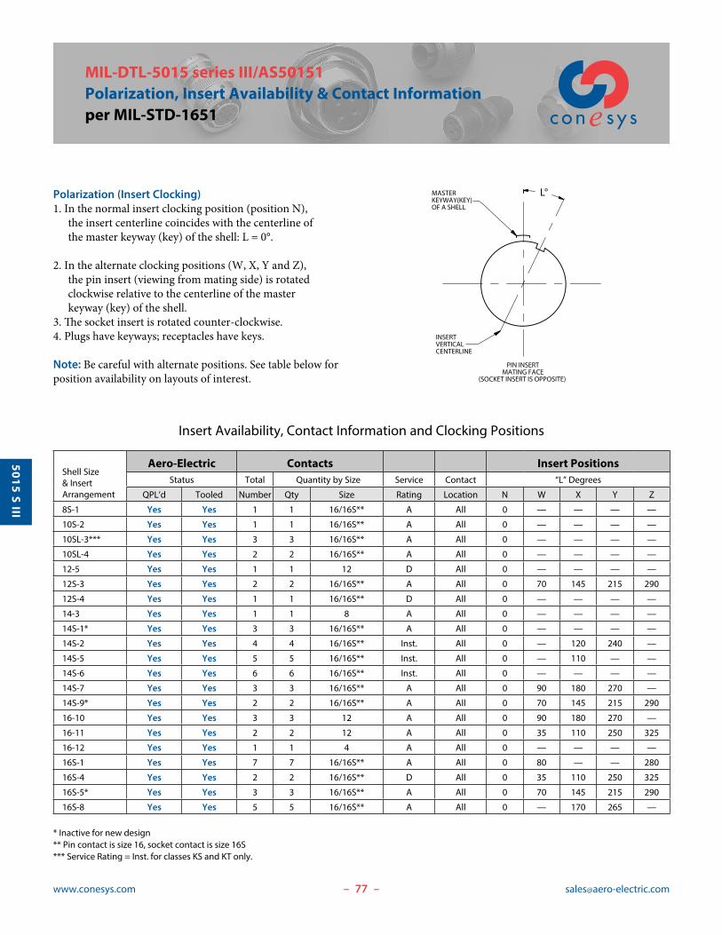
MIL-DTL-5015 series III/AS50151 Polarization, Insert Availability & Contact Informationper MIL-STD-1651
Insert Availability, Contact Information and Clocking Positions
Polarization (Insert Clocking) 1. In the normal insert clocking position (position N),
the insert centerline coincides with the centerline of the master keyway (key) of the shell: L = 0°.
2. In the alternate clocking positions (W, X, Y and Z), the pin insert (viewing from mating side) is rotated clockwise relative to the centerline of the master keyway (key) of the shell.
3. The socket insert is rotated counter-clockwise.4. Plugs have keyways; receptacles have keys.
Note: Be careful with alternate positions. See table below for position availability on layouts of interest.
* Inactive for new design ** Pin contact is size 16, socket contact is size 16S*** Service Rating = Inst. for classes KS and KT only.
Shell Size & Insert Arrangement
Aero-Electric Contacts Insert PositionsStatus Total Quantity by Size Service Contact “L” Degrees
QPL’d Tooled Number Qty Size Rating Location N W X Y Z
8S-1 Yes Yes 1 1 16/16S** A All 0 — — — —
10S-2 Yes Yes 1 1 16/16S** A All 0 — — — —
10SL-3*** Yes Yes 3 3 16/16S** A All 0 — — — —
10SL-4 Yes Yes 2 2 16/16S** A All 0 — — — —
12-5 Yes Yes 1 1 12 D All 0 — — — —
12S-3 Yes Yes 2 2 16/16S** A All 0 70 145 215 290
12S-4 Yes Yes 1 1 16/16S** D All 0 — — — —
14-3 Yes Yes 1 1 8 A All 0 — — — —
14S-1* Yes Yes 3 3 16/16S** A All 0 — — — —
14S-2 Yes Yes 4 4 16/16S** Inst. All 0 — 120 240 —
14S-5 Yes Yes 5 5 16/16S** Inst. All 0 — 110 — —
14S-6 Yes Yes 6 6 16/16S** Inst. All 0 — — — —
14S-7 Yes Yes 3 3 16/16S** A All 0 90 180 270 —
14S-9* Yes Yes 2 2 16/16S** A All 0 70 145 215 290
16-10 Yes Yes 3 3 12 A All 0 90 180 270 —
16-11 Yes Yes 2 2 12 A All 0 35 110 250 325
16-12 Yes Yes 1 1 4 A All 0 — — — —
16S-1 Yes Yes 7 7 16/16S** A All 0 80 — — 280
16S-4 Yes Yes 2 2 16/16S** D All 0 35 110 250 325
16S-5* Yes Yes 3 3 16/16S** A All 0 70 145 215 290
16S-8 Yes Yes 5 5 16/16S** A All 0 — 170 265 —
PIN INSERTMATING FACE
(SOCKET INSERT IS OPPOSITE)
INSERTVERTICALCENTERLINE
MASTERKEYWAY(KEY)OF A SHELL
L°

78www.conesys.com [email protected]
5015 S III
– –
MIL-DTL-5015 series III/AS50151 Insert Availability, Contact Information and Clocking
per MIL-STD-1651
Insert Availability, Contact Information and Clocking Positions
Shell Size & Insert Arrangement
Aero-Electric Contacts Insert PositionsStatus Total Quantity by Size Service Contact “L” Degrees
QPL’d Tooled Number Qty Size Rating Location N W X Y Z
18-1 Yes Yes 104 16 A B,C,F,G
0 70 145 215 2906 16 Inst. All others
18-4 Yes Yes 4 4 16 D All 0 35 110 250 325
18-5 Yes Yes 31 16
D All 0 80 110 250 2802 12
18-6 Yes Yes 1 1 4 D — 0 — — — —
18-8 Yes Yes 87 16
A All 0 70 — — 2901 12
18-9 Yes Yes 75 16
Inst. All 0 80 110 250 2802 12
18-10* Yes Yes 4 4 12 A All 0 — 120 240 —
18-11 Yes Yes 5 5 12 A All 0 — 170 265 —
18-12 Yes Yes 6 6 16 A All 0 80 — — 280
18-20* Yes Yes 5 5 16 A All 0 90 180 270 —
20-2 Yes Yes 1 1 0 D --- 0 — — — —
20-3* Yes Yes 3 3 12 D All 0 70 145 215 290
20-4 Yes Yes 4 4 12 D All 0 45 110 250 —
20-7 Yes Yes 84 16 D A,B,G,H
0 80 110 250 2804 16 A All others
20-8 Yes Yes 64 16
Inst. All 0 80 110 250 2802 8
20-11* Yes Yes 13 13 16 Inst. All 0 — — — —
20-14 Yes No 53 12
A All 0 80 110 250 2802 8
20-15 Yes Yes 7 7 12 A All 0 80 — — 280
20-16 Yes Yes 97 16
A All 0 80 110 250 2802 12
20-17 Yes Yes 61 16
A All 0 90 180 270 —5 12
20-18 Yes Yes 96 16
A All 0 35 110 250 3253 12
20-22 Yes Yes 63 16
A All 0 80 110 250 2803 8
20-24* Yes Yes 42 16
A All 0 35 110 250 3252 8
20-27 Yes Yes 14 14 16 A All 0 35 110 250 325
20-29 Yes Yes 17 17 16 A All 0 80 — — 280
20-33 Yes Yes 11 11 16 A All 0 — — — —
22-1* Yes Yes 2 2 8 D All 0 35 110 250 325
* Inactive for new design

79www.conesys.com [email protected]
5015 S III
– –
MIL-DTL-5015 series III/AS50151 Insert Availability, Contact Information and Clockingper MIL-STD-1651
Insert Availability, Contact Information and Clocking Positions
* Inactive for new design** Alternate positions X, Y are cancelled after June 26, 1968.
Shell Size & Insert Arrangement
Aero-Electric Contacts Insert PositionsStatus Total Quantity by Size Service Contact “L” Degrees
QPL’d Tooled Number Qty Size Rating Location N W X Y Z
22-2 Yes Yes 3 3 8 D All 0 70 145 215 290
22-9 Yes Yes 3 3 12 E All 0 70 145 215 290
22-12 Yes Yes 53 16
D All 0 80 110 250 2802 8
22-13* Yes Yes 51 16 D E
0 35 110 250 3254 12 A All others
22-14** Yes Yes 19 19 16 A All 0 80 110 250 280
22-18 Yes Yes 83 16 A C,D,E
0 80 110 250 2805 16 D All others
22-19 Yes Yes 14 14 16 A All 0 80 110 250 280
22-20* Yes Yes 9 9 16 A All 0 35 110 250 325
22-22 Yes Yes 4 4 8 A All 0 — 110 250 —
22-23 Yes Yes 81 12 D H
0 35 — 250 —7 12 A All others
22-27 Yes Yes 91 8 D J
0 80 — 250 2808 16 A All others
22-33* Yes Yes 73 16 A E,F,G
0 80 110 250 2804 16 D All others
24-2 Yes Yes 7 7 12 D All 0 80 — — 280
24-4 Yes Yes 43 16
D All 0 80 110 250 2801 0
24-6 Yes Yes 83 12 D A,G,H
0 80 110 250 2805 12 A All others
24-7 Yes Yes 1614 16
A All 0 80 110 250 2802 12
24-9* Yes Yes 2 2 4 A All 0 35 110 250 325
24-10 Yes Yes 7 7 8 A All 0 80 — — 280
24-11 Yes Yes 96 12
A All 0 35 110 250 3253 8
24-12 Yes Yes 53 12
A All 0 80 110 250 2802 4
24-20 Yes Yes 119 16
D All 0 80 110 250 2802 12
24-21 Yes No 109 16
D All 0 80 110 250 2801 8
24-22 Yes Yes 4 4 8 D All 0 45 110 250 —
24-27 Yes Yes 7 7 16 E All 0 80 — — 280
24-28 Yes Yes 24 24 16 Inst. All 0 80 110 250 280

80www.conesys.com [email protected]
5015 S III
– –
MIL-DTL-5015 series III/AS50151 Insert Availability, Contact Information and Clocking
per MIL-STD-1651
Insert Availability, Contact Information and Clocking Positions
Shell Size & Insert Arrangement
Aero-Electric Contacts Insert PositionsStatus Total Quantity by Size Service Contact “L” Degrees
QPL’d Tooled Number Qty Size Rating Location N W X Y Z
28-1 Yes Yes 9
2 12 D A,E
0 80 110 250 2804 12 A B,D,F,H
1 8 D J
2 8 A G,C
28-2 Yes Yes 1412 16
D All 0 35 110 250 3252 12
28-3 Yes Yes 3 3 8 E All 0 70 145 215 290
28-5 Yes Yes 5
2 16
D All 0 35 110 250 3251 12
2 4
28-8 Yes Yes 12
2 12 E L,M
1 16 D B 0 80 110 250 280
9 16 A All others
28-9 Yes Yes 126 16
D All 0 80 110 250 2806 12
28-11 Yes Yes 2218 16
A All 0 80 110 250 2804 12
28-12 Yes Yes 26 26 16 A All 0 90 180 270 —
28-15 Yes Yes 35 35 16 A All 0 80 110 250 280
28-16* Yes Yes 20 20 16 A All 0 80 110 250 280
28-19 Yes Yes 10
2 16 B H,M
0 80 110 250 2802 16 D A,B
2 16A All others
4 12
28-20 Yes Yes 144 16
A All 0 80 110 250 28010 12
28-21 Yes Yes 37 37 16 A All 0 80 110 250 280
28-22 Yes Yes 63 16
D All 0 70 145 215 2903 4
32-1 Yes Yes 5
1 12 E A
0 80 110 250 2802 12D
D,C
2 0 B,E
32-3 Yes Yes 9
4 16
D All 0 80 110 250 2802 12
2 4
1 0
32-5* Yes Yes 2 2 0 D All 0 80 110 250 325
32-6 Yes Yes 23
16 16
A All 0 80 110 250 2802 12
3 8
2 4
* Inactive for new design

81www.conesys.com [email protected]
5015 S III
– –
MIL-DTL-5015 series III/AS50151 Insert Availability, Contact Information and Clockingper MIL-STD-1651
Insert Availability, Contact Information and Clocking Positions
* Inactive for new design
** Alternate positions U (100 degrees) and V (260 degrees) are also available per MIL-STD-1651.
Shell Size & Insert Arrangement
Aero-Electric Contacts Insert PositionsStatus Total Quantity by Size Service Contact “L” Degrees
QPL’d Tooled Number Qty Size Rating Location N W X Y Z
32-7 Yes Yes 35
4 16 Inst. A,B,h,j
0 80 125 235 28024 16A All others
7 12
32-8* Yes Yes 3024 16
A All 0 80 125 235 2806 12
32-10* Yes Yes 7
2 16 E A,F
0 80 110 250 2801 16 B G
2 8 D B,E
2 4 A C,D
32-15 Yes Yes 86 12
D All 0 35 110 250 2802 0
32-17 Yes Yes 4 4 4 D All 0 45 110 250 ---
32-22** Yes Yes 54 54 16 A All 0 80 110 250 280
32-63 Yes Yes 5 5 4 D All 0 — — — —
32-73 Yes Yes 46 46 16 A All 0 36 — — —
36-3 Yes No 63 12
D All 0 70 145 215 2903 0
36-5 Yes Yes 4 4 0 A All 0 — 120 240 —
36-6 Yes Yes 64 4
A All 0 35 110 250 3252 0
36-7 Yes Yes 4740 16
A All 0 80 110 250 2807 12
36-8 Yes Yes 4746 16
A All 0 80 110 250 2801 12
36-9 Yes Yes 31
14 16
A All 0 80 125 235 28014 12
2 8
1 4
36-10 Yes Yes 48 48 16 A All 0 80 125 235 280
40-10 Yes Yes 29
16 16
A All 0 65 125 225 3109 8
4 4
40-56 Yes Yes 85 85 16 A All 0 72 144 216 288

82www.conesys.com [email protected]
5015 S III
– –
MIL-STD-1651Insert Arrangements (Pin Front View)
for MIL-DTL-5015 Connectors
Insert Arrangement Views
A
BC
D
8S-11- #16
10S-21- #16
A
B
C
10SL-33- #16
A B
10SL-42- #16
AB
12S-32- #16
12S-41- #16
12-51- #12
A
B
C
14S-1*3- #16
A
BC
D
14S-24- #16
14-31- #8
A
B
CD
E
14S-55- #16
A
B
C
D
E
F
14S-66- #16
A
B
C
14S-73- #16
AB
14S-9*2- #16
A
B
CD
E
F
G
16S-17- #16
AB
16S-42- # 16
A
BC
16S-5*3- #16
A
BC
D
E
16S-85- #16
A
B
C
16-103- #12
A
B
16-112- #12
16-121- #4
A
I
J
B
C
DE
G
H
F
18-110- #16
A
BC
D
18-44- #16
A
BC
D
E
18-115- #12
A
B
C
D
E
F
18-126- #16
A B
C
D
E
18-20*5- # 16
A
BC
18-51- #16, 2- #12
18-61- #4
A
B
CD
E
G
H
F
18-87- #16, 1- #12
A
B
C
D
E
G
F
18-95- #16, 2- #12
18-10*4- #12
20-21- #0
A
BC
20-3*3- #12
* Inactive for new design

83www.conesys.com [email protected]
5015 S III
– –
MIL-STD-1651Insert Arrangements (Pin Front View)for MIL-DTL-5015 Connectors
Insert Arrangement Views
20-157- #12
20-24*2- #16, 2- #8
A
B
C
D
EF
G
H
J
K
L
M
N
I
20-2714- #16
AB
C
D
E
T
FG
H
J
K
L
M
N
P
RS
20-2917- #16
A
B
C
D
E
F
H
J
K
L
M
20-3311- #16
20-167- #16, 2- #12
20-171- #16, 5- #12
20-186- #16, 3- #12
20-223- #16, 3- #8
AB
22-1*2- #8
22-23- #8
A
B
C
D
E
F
G
HI
A
B
CD
E
F
G
A
BC
D
E
F
A
B
CDE
F
G H
I
A
B
C
D
E
F
A
B
C
D
A
BC
A
BC
22-93- #12
22-123- #16, 2- #8
A
B
CD
E
22-13*1- #16, 4- #12
A
BC
D
E
A
B
C
D
EF
G
H
J
K
L M
N
P
RS
V
U
T
22-1419- #16
A
B
C
DE
G
H
F
A
BC
D
20-44- #12
20-78- #16
A
B
C
D
EF
20-84- #16, 2- #8
A
B C
D
EF
G H
J
K
L
M
N
20-11*13- #16
A
BC
D
E
20-143- #12, 2- #8
* Inactive for new design

84www.conesys.com [email protected]
5015 S III
– –
MIL-STD-1651Insert Arrangements (Pin Front View)
for MIL-DTL-5015 Connectors
Insert Arrangement Views
AB
A
B
CD
E
F
G
A
B
C
D
E
F
H
J K
G
A
BC
D
A
B
C
D
E
F
G
A B C D
JE F H
K L M N P Q
R S T U V
W X Y Z
G
24-714- #16, 2- #12
24-9*2- #4
24-107- #8
24-116- #12, 3- #8
24-123- #12, 2- #4
24-209- #16, 2- #12
24-219- #16, 1- #8
24-224- #8
24-277- #16
24-2824- #16
A
B
CL
D
EF
H
G
J
K
A B C
D E F
H JG
A
B
C
D
E
AB
C
D
E
F
G
H
I
J
K
L
M
N
O
P
B
A
C
D
E
F
G
H
22-188- #16
A
B
JC
D
E
F
G
H A
BC
D
E
FG
22-271- #8, 8- #16
22-33*7- #16
AB
C
D
EF
G
H
J
K
L
M
N
P
22-1914- #16
A
B
CDE
F
G H
J
22-20*9- #16
A
BC
D
22-224- #8
A
B
C
D
E
F
G
H
22-238- #12
A
B
CD
E
F
G
24-27- #12
A
B
C
D
24-43- #16, 1- #0
A
B
C
D
E
FH
G
24-68- #12
* Inactive for new design

85www.conesys.com [email protected]
5015 S III
– –
MIL-STD-1651Insert Arrangements (Pin Front View)for MIL-DTL-5015 Connectors
Insert Arrangement Views
28-16- #12, 3- #8
28-212- #16, 2- #12
28-33- #8
28-52- #16, 1- #12, 2- #4
28-82- #12, 10- #16
28-96- #16, 6- #12
28-1118- #16, 4- #12
28-1226- #16
28-1535- #16
28-16*20- #16
28-196- #16, 4- #12
28-204- #16, 10- #12
28-2137- #16
28-223- #16, 3- #4
32-13- #12, 2- #0
A
P
B
C
D
EF
G
H
J
K
L
M
N
A B
C
DEF
H
JG
A
BC
A
B
CD
E
A
B
CD
E
F
G
H
J
K
L
M
A
B
C
DE
F
G
H
J
K
LM
A
B
C
D
E
F
G
H
I
J
K
L
M
N
P
R
S
T
U
V
W
X
A
B
C
D
E
F
GH
J
K
L
M
N
P
R
S
T
U
V
WX
Y
Z
a
b
d
A
a b c
d e f g h
l
j k
m
B
C D E F G
H J K L M N
P R S T U V W
X Y Z
A B
C
D
EFG
H
J
K
L M
N
PQR
S
T
UV
A B
C
E
G
H
J
K
L
M
A
B
C
D
E
F
G
H
J
K
LM
N
P
A B C D
E F G H J
K L M N P R
S T U V W X Z
a b c d e f
g h j k m
np r
s
A
B
C
DE
FA
B
CD
E
32-34- #16, 2- #12,
2- #4, 1- #0
A B C
D
E
F
GH
J
* Inactive for new design

86www.conesys.com [email protected]
5015 S III
– –
MIL-STD-1651Insert Arrangements (Pin Front View)
for MIL-DTL-5015 Connectors
Insert Arrangement Views
32-5*2- #0
32-728- #16, 7- #12
32-8*24- #16, 6- #12
32-10*3- #16, 2- #8,
2- #4
32-156- #12, 2- #0
32-174- #4
32-2254- #16
32-635- #4
32-7346- #16
36-33- #12, 3- #0
36-54- #0
A
B
32-616- #16, 2- #12,
3- #8, 2- #4
A
B
C
D
E
F
G
H
I
J
K
L
M
N
O
P
R
S
T
U
V
W
X
Y
Z
a
b
c
d
e
A
B
C
D
A
B
C
D
E
F
A
B C
D E
F
G
H
A
B
C
D
E
A
BC
D
A
B
CD
G
F
E
A BC D
E FG H
I JKL M
N
PO R S
T
U V
W X
A
B
C
D
E
F
G
H
I
J
K
L
M
N
O
P
R
S
T
UV
W
X
Y
Z
a
b
c
d
e
f
g
h
j
k
A BC D E
F G H J
X Y
KL
M
N P RO
S T U V W
Z ab c d e f
g h j k
m n p qr
y
s t u v
w xz AA
AB
AC
ADAF AG
AE
12
3
4
5
6
7
8
9
101112
13
14
15
16
17
18
19
2021
22
23
24
25
26
27
28
293031
32
33
34
35
36
37
38
39
4041
42
43
44
45
46
* Inactive for new design

87www.conesys.com [email protected]
5015 S III
– –
MIL-STD-1651Insert Arrangements (Pin Front View)for MIL-DTL-5015 Connectors
Insert Arrangement Views
36-914- #16, 14- #12,
2- #8, 1- #4
36-1048- #16 40-10
16- #16, 9- #8,4- #4
40-5685- #16
A
B
C
D
E
H
F
G
I
J
K
L
M
N
O
P
R
S
T
U
V
W
X
Y
Z
a
b
c
d
e
f
A B
C D E F G
H J K L M N
O P Q R S T U
V W X Y Z a b c
d e f g h j k
m n p q r s
t u v w x
y z
A
BC D
E
FG
H
I
J K
L
M N OP Q
R
S T
U
VW X
Y
Z a
b
c
A B C D
E F H J K L M
N P R S T U V W
X Y Z a b c d f g
h j ki m n p q r s
t u v w x y z AA AB
AC AD AE AF AH AJ AK AL AM AN
AP AR AS AT AU AV AW AX AY
AZ BA BB BC BD BE BF BH
BJ BK BL BM BN BP BR
BS BT BU BV
36-64- #4, 2- #0
36-740- #16, 7- #12
36-846- #16, 1- #12
A
B
C
D
E
F
A BC D E
F G
H I J
K L M N
OP R S T
U V W X
Y Z a b c
md e f g
h jt
k
n p
u w vr s
xz
y
A
BC
D EF
G H
I J K LMN O P R
S T U V
W XY
Z a
bc d e
fg h
y
jk
w
mn
x
p
z
rs tu
v


![Application Programming Interface (API) Reference Guide · API commands ... Video Input Connector [n] ... Video Input Connector [n] Name . Video Input Connector [n] PresentationSelection](https://img.pdfslide.net/doc/110x75/5b74ccc67f8b9aa01f8c8f90/application-programming-interface-api-reference-guide-api-commands-video.jpg)