Embed Size (px)
Citation preview

We Provide the Light to the world
No. 89, Xiyuan Rd., Zhongli City, Taoyuan County 320,
Taiwan (R.O.C.)
Tel :+886-3-461-8618
Fax :+886-3-461-8677
www.prolightopto.com
ProLight PBLA-10LTE10W Power LED Technical DatasheetVersion: 1.1
Features‧Compact light source‧R, G, B, W four color in one package‧Maximum drive current: 700mA per LED die‧Lead free reflow soldering‧Superior ESD protection‧RoHS compliant
Main Applications ‧Entertainment lighting (Stage lighting)‧Architectural lighting‧Mood lighting‧Outdoor lighting‧Indoor lighting
Introduction‧ ProLight PBLA colorful series is a color changeable LED with maximum 4 color chips in one package. Compared to discrete LEDs, PBLA series reduce the distance between LED die, creating a small optical source for excellent optical control and efficient color mixing. ProLight PBLA series is much suitable for theapplication of color-changing lighting, especially for entertainment lighting.
2016/11DS-0586

We Provide the Light to the world
No. 89, Xiyuan Rd., Zhongli City, Taoyuan County 320,
Taiwan (R.O.C.)
Tel :+886-3-461-8618
Fax :+886-3-461-8677
www.prolightopto.com
2
Notes:
1. Drawing not to scale.
2. All dimensions are in millimeters.
3. Unless otherwise indicated, tolerances are ± 0.15mm.
4. Please do not solder the emitter by manual hand soldering, otherwise it will damage the emitter.
5. Please do not use a force of over 1kgf impact or pressure on the lens of the LED, otherwise
it will cause a catastrophic failure.
*The appearance and specifications of the product may be modified for improvement without notice.
Emitter Mechanical Dimensions
::::

We Provide the Light to the world
No. 89, Xiyuan Rd., Zhongli City, Taoyuan County 320,
Taiwan (R.O.C.)
Tel :+886-3-461-8618
Fax :+886-3-461-8677
www.prolightopto.com
Thermal
Forward Voltage VF (V) Forward Voltage VF (V) Resistance
@350mA Refer @700mA Junction to
Color Min. Typ. Max. Typ. Slug (°C/ W)
Red 1.80 2.30 2.60 2.60
3.5Green 2.80 3.20 3.60 3.60
Blue 2.80 3.10 3.60 3.50
White 2.80 3.10 3.60 3.35
● ProLight maintains a tolerance of ± 0.1V for Voltage measurements.
Luminous Flux ΦV (lm)
Part Number @350mA Refer @700mA
Color Emitter Minimum Typical Minimum Typical
Red
PBLA-10LTE
51 61 94 114
Green 90 106 137 166
Blue 18 22 31 39
White 116 136 193 233
● ProLight maintains a tolerance of ± 7% on flux and power measurements.● Please do not drive at rated current more than 1 second without proper heat sink.
3
Flux Characteristics, TJ = 25°C
Electrical Characteristics, TJ = 25°C
Optical Characteristics at 350mA, TJ = 25°C Total
included Viewing
Dominant Wavelength λD, Angle Angle
RadiationColor
or Color Temperature CCT (degrees) (degrees)
Pattern Min. Typ. Max. θ0.90V 2 θ1/2
Lambertian
Red 620 nm 623 nm 630 nm
170 155Green 520 nm 525 nm 530 nm
Blue 455 nm 458 nm 460 nm
White 5700 K 6350 K 7000 K
● ProLight maintains a tolerance of ± 1nm for dominant wavelength measurements.
● ProLight maintains a tolerance of ± 5% for CCT measurements.

We Provide the Light to the world
No. 89, Xiyuan Rd., Zhongli City, Taoyuan County 320,
Taiwan (R.O.C.)
Tel :+886-3-461-8618
Fax :+886-3-461-8677
www.prolightopto.com
4
Absolute Maximum RatingsParameter Red/Green/Blue/White
DC Forward Current (mA) 700
Peak Pulsed Forward Current (mA) 1000 (less than 1/10 duty cycle@1KHz)
ESD Sensitivity±4000V (Class III)
(HBM per MIL-STD-883E Method 3015.7)
LED Junction Temperature 120°C
Operating Board Temperature-40°C - 90°C
at Maximum DC Forward Current
Storage Temperature -40°C - 120°C
Soldering Temperature JEDEC 020c 260°C
Allowable Reflow Cycles 3
Reverse Voltage Not designed to be driven in reverse bias
Photometric Luminous Flux Bin Structure at 350mA
Color Bin CodeMinimum Maximum
Photometric Flux (lm) Photometric Flux (lm)
Red 0 51 77
Green 0 90 126
Blue 0 18 27
White 0 116 150
● ProLight maintains a tolerance of ± 7% on flux and power measurements.● The flux bin of the product may be modified for improvement without notice.

We Provide the Light to the world
No. 89, Xiyuan Rd., Zhongli City, Taoyuan County 320,
Taiwan (R.O.C.)
Tel :+886-3-461-8618
Fax :+886-3-461-8677
www.prolightopto.com
5
Color BinWhite Binning Structure Graphical Representation
White Bin Structure
Bin Code x yTyp. CCT
(K)Bin Code x y
Typ. CCT
(K)
WG
0.3290 0.3690
6025 WF
0.3140 0.3550
66750.3290 0.3450 0.3160 0.3320
0.3160 0.3320 0.3060 0.3220
0.3140 0.3550 0.3010 0.3420
WD
0.3290 0.3450
6025 WC
0.3160 0.3320
66750.3290 0.3300 0.3170 0.3190
0.3170 0.3190 0.3080 0.3110
0.3160 0.3320 0.3060 0.3220
WP
0.3170 0.3190
6025 WN
0.3080 0.3110
66750.3290 0.3300 0.3170 0.3190
0.3290 0.3180 0.3180 0.3080
0.3180 0.3080 0.3100 0.3000
● Tolerance on each color bin (x , y) is ± 0.005
0.26
0.28
0.30
0.32
0.34
0.36
0.38
0.40
0.24 0.26 0.28 0.30 0.32 0.34 0.36 0.38
y
x
Planckian(BBL)
5700 K
6350 K
WF
White
WC
WN
WG
WD
WP
7000 K

We Provide the Light to the world
No. 89, Xiyuan Rd., Zhongli City, Taoyuan County 320,
Taiwan (R.O.C.)
Tel :+886-3-461-8618
Fax :+886-3-461-8677
www.prolightopto.com
Color Bin CodeMinimum Dominant Maximum Dominant
Wavelength (nm) Wavelength (nm)
Red 4 620 630
Green 1 520 530
Blue A 455 460
● ProLight maintains a tolerance of ± 1nm for dominant wavelength measurements.
Note: Although several bins are outlined, product availability in a particular bin varies by production run
and by product performance. Not all bins are available in all colors.
Dominant Wavelength Bin Structure
6
Forward Voltage Bin Structure Color Bin Code Minimum Voltage (V) Maximum Voltage (V)
Red 0 1.8 2.6
Green 0 2.8 3.6
Blue 0 2.8 3.6
White 0 2.8 3.6
● ProLight maintains a tolerance of ± 0.1V for Voltage measurements.
Note: Although several bins are outlined, product availability in a particular bin varies by production run
and by product performance. Not all bins are available in all colors.

We Provide the Light to the world
No. 89, Xiyuan Rd., Zhongli City, Taoyuan County 320,
Taiwan (R.O.C.)
Tel :+886-3-461-8618
Fax :+886-3-461-8677
www.prolightopto.com
7
0.0
0.2
0.4
0.6
0.8
1.0
350 400 450 500 550 600 650 700 750 800 850
Rela
tive S
pectr
al P
ow
er
Dis
trib
ution
Wavelength (nm)
Color Spectrum, TJ = 25°C
2. White
Standard Eye Response Curve
White
1. Blue、Green、Red
0.0
0.2
0.4
0.6
0.8
1.0
400 450 500 550 600 650 700
Rela
tive S
pectr
al P
ow
er
Dis
trib
ution
Wavelength (nm)
Blue Green Red

We Provide the Light to the world
No. 89, Xiyuan Rd., Zhongli City, Taoyuan County 320,
Taiwan (R.O.C.)
Tel :+886-3-461-8618
Fax :+886-3-461-8677
www.prolightopto.com
0
20
40
60
80
100
120
140
160
0 20 40 60 80 100 120
Rela
tive L
ight
Outp
ut
(%)
Junction Temperature, TJ (℃)
Green, White
Blue
0
20
40
60
80
100
120
140
160
0 20 40 60 80 100 120
Rela
tive L
ight
Outp
ut
(%)
Junction Temperature, TJ (℃)
Red
8
Light Output CharacteristicsRelative Light Output vs. Junction Temperature at 700mA

We Provide the Light to the world
No. 89, Xiyuan Rd., Zhongli City, Taoyuan County 320,
Taiwan (R.O.C.)
Tel :+886-3-461-8618
Fax :+886-3-461-8677
www.prolightopto.com
0.0
0.2
0.4
0.6
0.8
1.0
1.2
1.4
1.6
1.8
2.0
0 200 400 600 800
Rela
tive
Lu
min
ou
s F
lux
Forward Current (mA)
Blue, White
0.0
0.2
0.4
0.6
0.8
1.0
1.2
1.4
1.6
1.8
0 200 400 600 800
Rela
tive
Lu
min
ou
s F
lux
Forward Current (mA)
Green
0.0
0.2
0.4
0.6
0.8
1.0
1.2
1.4
1.6
1.8
2.0
0 200 400 600 800
Rela
tive
Lu
min
ou
s F
lux
Forward Current (mA)
Red
0
100
200
300
400
500
600
700
800
0 0.5 1 1.5 2 2.5 3 3.5 4
Ave
rag
e F
orw
ard
Cu
rre
nt (m
A)
Forward Voltage (V)
0
100
200
300
400
500
600
700
800
0 0.5 1 1.5 2 2.5 3
Ave
rag
e F
orw
ard
Cu
rre
nt (m
A)
Forward Voltage (V)
9
Forward Current Characteristics, TJ = 25°C 1. Forward Voltage vs. Forward Current
RedGreen, Blue,
White
2. Forward Current vs. Normalized Relative Luminous Flux

We Provide the Light to the world
No. 89, Xiyuan Rd., Zhongli City, Taoyuan County 320,
Taiwan (R.O.C.)
Tel :+886-3-461-8618
Fax :+886-3-461-8677
www.prolightopto.com
Lambertian Radiation Pattern
0
10
20
30
40
50
60
70
80
90
100
-100 -80 -60 -40 -20 0 20 40 60 80 100
Rela
tive I
nte
nsity
(%)
Angular Displacement (Degrees)
10
Board Temperature vs. Maximum Forward CurrentMaximum Forward Current for 4 chip operated
Typical Representative Spatial Radiation Pattern
0
100
200
300
400
500
600
700
800
0 20 40 60 80 100
Forw
ard
Curr
ent
(mA
)
Board Temperature (℃)
We Provide the Light to the world
No. 89, Xiyuan Rd., Zhongli City, Taoyuan County 320,
Taiwan (R.O.C.)
Tel :+886-3-461-8618
Fax :+886-3-461-8677
www.prolightopto.com
11
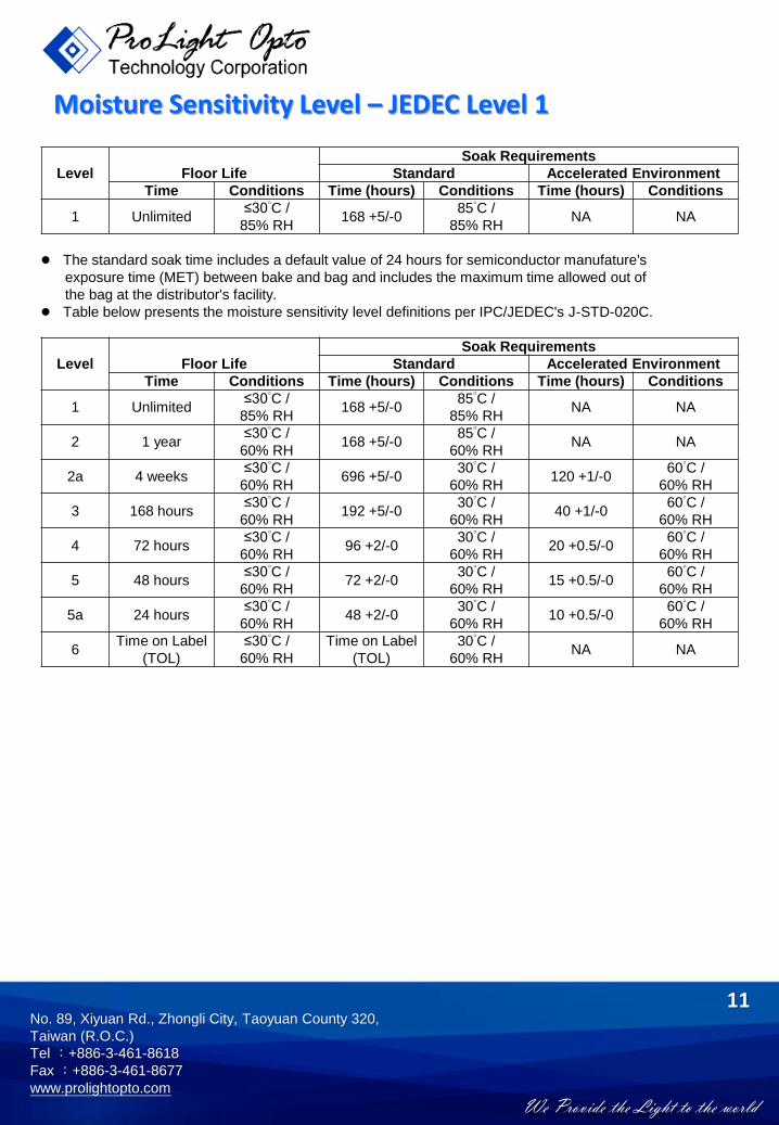
Soak Requirements
Level Floor Life Standard Accelerated Environment
Time Conditions Time (hours) Conditions Time (hours) Conditions
1 Unlimited≤30°C /
168 +5/-085°C /
NA NA85% RH 85% RH
● The standard soak time includes a default value of 24 hours for semiconductor manufature's
exposure time (MET) between bake and bag and includes the maximum time allowed out of
the bag at the distributor's facility.● Table below presents the moisture sensitivity level definitions per IPC/JEDEC's J-STD-020C.
Soak Requirements
Level Floor Life Standard Accelerated Environment
Time Conditions Time (hours) Conditions Time (hours) Conditions
1 Unlimited≤30°C /
168 +5/-085°C /
NA NA85% RH 85% RH
2 1 year≤30°C /
168 +5/-085°C /
NA NA60% RH 60% RH
2a 4 weeks≤30°C /
696 +5/-030°C /
120 +1/-060°C /
60% RH 60% RH 60% RH
3 168 hours≤30°C /
192 +5/-030°C /
40 +1/-060°C /
60% RH 60% RH 60% RH
4 72 hours≤30°C /
96 +2/-030°C /
20 +0.5/-060°C /
60% RH 60% RH 60% RH
5 48 hours≤30°C /
72 +2/-030°C /
15 +0.5/-060°C /
60% RH 60% RH 60% RH
5a 24 hours≤30°C /
48 +2/-030°C /
10 +0.5/-060°C /
60% RH 60% RH 60% RH
6Time on Label ≤30°C / Time on Label 30°C /
NA NA(TOL) 60% RH (TOL) 60% RH
Moisture Sensitivity Level – JEDEC Level 1

We Provide the Light to the world
No. 89, Xiyuan Rd., Zhongli City, Taoyuan County 320,
Taiwan (R.O.C.)
Tel :+886-3-461-8618
Fax :+886-3-461-8677
www.prolightopto.com
12
Stress Test Stress ConditionsStress
DurationFailure Criteria
Room Temperature25°C, IF = max DC (Note 1) 1000 hours Note 2
Operating Life (RTOL)
Wet High Temperature85°C/85%RH, non-operating 1000 hours Note 2
Storage Life (WHTSL)
High Temperature110°C, non-operating 1000 hours Note 2
Storage Life (HTSL)
Low Temperature-40°C, non-operating 1000 hours Note 2
Storage Life (LTSL)
Non-operating -40°C to 120°C, 30 min. dwell,200 cycles Note 2
Temperature Cycle (TMCL) <5 min. transfer
Mechanical Shock1500 G, 0.5 msec. pulse,
Note 35 shocks each 6 axis
Natural Drop On concrete from 1.2 m, 3X Note 3
Variable Vibration 10-2000-10 Hz, log or linear sweep rate,Note 3
Frequency 20 G about 1 min., 1.5 mm, 3X/axis
Solder Heat Resistance260°C ± 5°C, 10 sec. Note 3
(SHR)
SolderabilitySteam age for 16 hrs., then solder dip Solder coverage
at 260°C for 5 sec. on lead
Notes:
1. Depending on the maximum derating curve.
2. Criteria for judging failure
Item Test ConditionCriteria for Judgement
Min. Max.
Forward Voltage (VF) IF = max DC -- Initial Level x 1.1
Luminous Flux or IF = max DC Initial Level x 0.7 --
Radiometric Power (ΦV)
Reverse Current (IR) VR = 5V -- 50 μA
* The test is performed after the LED is cooled down to the room temperature.
3. A failure is an LED that is open or shorted.
Qualification Reliability Testing

We Provide the Light to the world
No. 89, Xiyuan Rd., Zhongli City, Taoyuan County 320,
Taiwan (R.O.C.)
Tel :+886-3-461-8618
Fax :+886-3-461-8677
www.prolightopto.com
● All dimensions are in millimeters.
● Electrical isolation is required between Slug and Solder Pad.
13
Recommended Solder Pad Design

We Provide the Light to the world
No. 89, Xiyuan Rd., Zhongli City, Taoyuan County 320,
Taiwan (R.O.C.)
Tel :+886-3-461-8618
Fax :+886-3-461-8677
www.prolightopto.com
14
Reflow Soldering ConditionProfile Feature Sn-Pb Eutectic Assembly Pb-Free Assembly
Average Ramp-Up Rate3°C / second max. 3°C / second max.
(TSmax to TP)Preheat– Temperature Min (TSmin) 100°C 150°C– Temperature Max (TSmax) 150°C 200°C– Time (tSmin to tSmax) 60-120 seconds 60-180 seconds
Time maintained above:– Temperature (TL) 183°C 217°C– Time (tL) 60-150 seconds 60-150 seconds
Peak/Classification Temperature (TP) 240°C 260°CTime Within 5°C of Actual Peak
10-30 seconds 20-40 secondsTemperature (tP)Ramp-Down Rate 6°C/second max. 6°C/second max.Time 25°C to Peak Temperature 6 minutes max. 8 minutes max.
● We recommend using the M705-S101-S4 solder paste from SMIC (Senju Metal Industry Co., Ltd.) for lead-free soldering.
● Do not use solder pastes with post reflow flux residue>47%. (58Bi-42Sn eutectic alloy, etc) This kindof solder pastes may cause a reliability problem to LED.
● All temperatures refer to topside of the package, measured on the package body surface.● Repairing should not be done after the LEDs have been soldered. When repairing is unavoidable, a
double-head soldering iron should be used. It should be confirmed beforehand whether thecharacteristics of the LEDs will or will not be damaged by repairing.
● Reflow soldering should not be done more than three times.● When soldering, do not put stress on the LEDs during heating.● After soldering, do not warp the circuit board.
t 25°C to Peak
tSPreheat
Time
Te
mp
era
ture
Critical Zone
TL to TPRamp-up
Ramp-down
TSmax
TSmin
tP
tL
TP
TL
25
IPC-020c

We Provide the Light to the world
No. 89, Xiyuan Rd., Zhongli City, Taoyuan County 320,
Taiwan (R.O.C.)
Tel :+886-3-461-8618
Fax :+886-3-461-8677
www.prolightopto.com
15
Emitter Reel Packaging
Notes:
1. Drawing not to scale.
2. All dimensions are in millimeters.
3. Unless otherwise indicated, tolerances are ± 0.10mm.

We Provide the Light to the world
No. 89, Xiyuan Rd., Zhongli City, Taoyuan County 320,
Taiwan (R.O.C.)
Tel :+886-3-461-8618
Fax :+886-3-461-8677
www.prolightopto.com
16
Emitter Reel Packaging
Notes:
1. Empty component pockets sealed with top cover tape.
2. 250 or 500 pieces per reel.
3. Drawing not to scale.
4. All dimensions are in millimeters.

We Provide the Light to the world
No. 89, Xiyuan Rd., Zhongli City, Taoyuan County 320,
Taiwan (R.O.C.)
Tel :+886-3-461-8618
Fax :+886-3-461-8677
www.prolightopto.com
17
● We recommend using the M705-S101-S4 solder paste from SMIC (Senju Metal Industry
Co., Ltd.) for lead-free soldering.
● Do not use solder pastes with post reflow flux residue>47%. (58Bi-42Sn eutectic alloy, etc) This
kind of solder pastes may cause a reliability problem to LED.
●Any mechanical force or any excess vibration shall not be accepted to apply during cooling
process to normal temperature after soldering.
●Please avoid rapid cooling after soldering.
●Components should not be mounted on warped direction of PCB.
●Repairing should not be done after the LEDs have been soldered. When repairing is unavoidable,
a heat plate should be used. It should be confirmed beforehand whether the characteristics of
the LEDs will or will not be damaged by repairing.
●This device should not be used in any type of fluid such as water, oil, organic solvent and etc.
When cleaning is required, isopropyl alcohol should be used.
●When the LEDs are illuminating, operating current should be decide after considering the
package maximum temperature.
●The appearance, specifications and flux bin of the product may be modified for improvement
without notice. Please refer to the below website for the latest datasheets.
http://www.prolightopto.com/
Precaution for Use
Handling of Lens LEDsNotes for handling of lens LEDs
●Please do not use a force of over 1kgf impact or pressure on the lens, otherwise it will cause a
catastrophic failure.
●The LEDs should only be picked up by making contact with the sides of the LED body.
●Avoid touching the lens especially by sharp tools such as Tweezers.
●Avoid leaving fingerprints on the lens.
●Please store the LEDs away from dusty areas or seal the product against dust.
●Please do not mold over the lens with another resin. (epoxy, urethane, etc)