Embed Size (px)
Citation preview

Features of Power-Sonic Sealed Lead Acid Batteries .................................................1
Battery Construction ........................................................................................................2
Theory of Operation ..................................................................................................3 & 4
Battery Capacity ........................................................................................................5 & 6
Battery Capacity Selector ................................................................................................7
Performance Data ............................................................................................................8 Discharge..................................................................................................................................8 OpenCircuitVoltage.................................................................................................................8 Temperature.............................................................................................................................9 ShelfLifeandStorage...........................................................................................................10 BatteryLife.......................................................................................................................10-11 OverDischarge.......................................................................................................................12
Charging ...........................................................................................................................12 ChargingTechniquesSummary............................................................................................13 ChargingCharacteristics........................................................................................................13 ChargingMethods..................................................................................................................13 ConstantVoltageCharging....................................................................................................14 ConstantCurrentCharging....................................................................................................15 Taper-CurrentCharging..........................................................................................................15 Overcharging..........................................................................................................................16 Undercharging........................................................................................................................16 ChargingforCycleOperation.................................................................................................16 ChargingforStandbyOperation............................................................................................16 Two-StepConstantVoltageCharging....................................................................................17 CharginginSeries..................................................................................................................17 CharginginParallel................................................................................................................18 TemperatureCompensation..................................................................................................18 TopCharging...........................................................................................................................18 ChargingEfficiency.................................................................................................................19
Important Do’s and Don’ts ............................................................................................20 Handling..................................................................................................................................20 Installation..............................................................................................................................20 Charging..................................................................................................................................21
Notes ................................................................................................................................22
Glossary ...........................................................................................................................24
Table of Contents
Sealed/Maintenance–FreeThevalveregulatedspillproofconstructionallowstrouble-freesafeoperationinanyposition.Thereisnoneedtoaddelectrolyte,asgasesgeneratedduringthechargephasearerecombinedinaunique“oxygencycle”.
Power-Sonicsealedleadacidbatteriescanbeoperatedinvirtuallyanyorientationwithoutthelossofcapacityorelectrolyteleakage.However,upsidedownoperationisnotrecommended.
Long Shelf LifeAlowself-dischargerate,uptoapproximately3%permonth,mayallowstorageoffullychargedbatteriesforuptoayear,dependingonstoragetemperatures,beforechargingbecomescritical.However, we strongly recommend that all batteries should be recharged within six months of receipt as it will enhance their long term life.
PleaserefertothisTechnicalManualandindividualbatteryspecificationsheetsformoredetails.
Design FlexibilitySamemodelbatteriesmaybeusedinseriesand/orparalleltoobtainchoiceofvoltageandcapacity.Thesamebatterymaybeusedineithercyclicorstandbyapplications.Over80modelsavailabletochoosefrom.
Deep Discharge RecoverySpecialseparators,advancedplatecompositionandacarefullybalancedelectrolytesystemensurethatthebatteryhastheabilitytorecoverfromexcessivelydeepdischarge.
EconomicalThehighwatt-hourperdollarvalueismadepossiblebythematerialsusedinasealedlead-acidbattery;theyarereadilyavailableandlowincost.
Easy HandlingNospecialhandlingprecautionsorshippingcontainers,surfaceorair,arerequiredduetotheleak-proofconstruction.PleaserefertothedeclarationofnonrestrictedstatusforD.O.T.andI.A.T.A.aslistedintheLiteraturesectionofourwebsite:www.power-sonic.com.
CompactPower-Sonicbatteriesutilizestateoftheartdesign,highgradematerials,andacarefullycontrolledplate-makingprocesstoprovideexcellentoutputpercell.Thehighenergydensityresultsinsuperiorpower/volumeandpower/weightratios.
Low Pressure Valve RegulatorsAllbatteriesfeatureaseriesoflowpressureone-wayreliefvalves.Thesevalvessafelyreleaseanyexcessiveaccumulationofgasinsidethebatteryandthenreseal.
High Discharge RateLowinternalresistanceallowsdischargecurrentsofuptotentimestheratedcapacityofthebattery.Relativelysmallbatteriesmaythusbespecifiedinapplicationsrequiringhighpeakcurrents.
Wide Operating Temperature RangePower-Sonicbatteriesmaybedischargedoveratemperaturerangeof-40°Cto+60°C(-40°Fto+140°F)andchargedattemperaturesrangingfrom-20°Cto+50°C(-4°Fto+122°F).
Rugged ConstructionThehighimpactresistantbatterycaseismadeofnon-conductiveABSplastic.Thecasematerialsimpartgreatresistancetoshock,vibration,chemicalsandheat.FlameRetardant(FR)batterycasesandlidsareavailablewheretheendapplicationdictates.
Long Service LifePS/PSHandPSGSeries:Haveadesignlifeofuptofiveyearsinstandbyapplications.Incyclicalapplicationsupto1,000charge/dischargecyclescanbeexpecteddependingonaveragedepthofdischarge.
PGSeries:Haveadesignlifeofupto10yearsinfloatapplications.
PleaseconsultthisTechnicalManualandproductspecificationstobecomeawareofthemanyfactorsthateffectproductlife.
Theinformationcontainedwithinisprovidedasaservicetoourcustomersandisfortheirinformationonly.Theinformationandrecommendationssetforthhereinaremadeingoodfaithandarebelievedtobeaccurateatthedate
compiled.Power-SonicCorporationmakesnowarrantyexpressedorimplied.
Features of Power-Sonic Sealed Lead Acid Batteries
POWER-SONIC Rechargeable Batteries �
�
Battery Construction
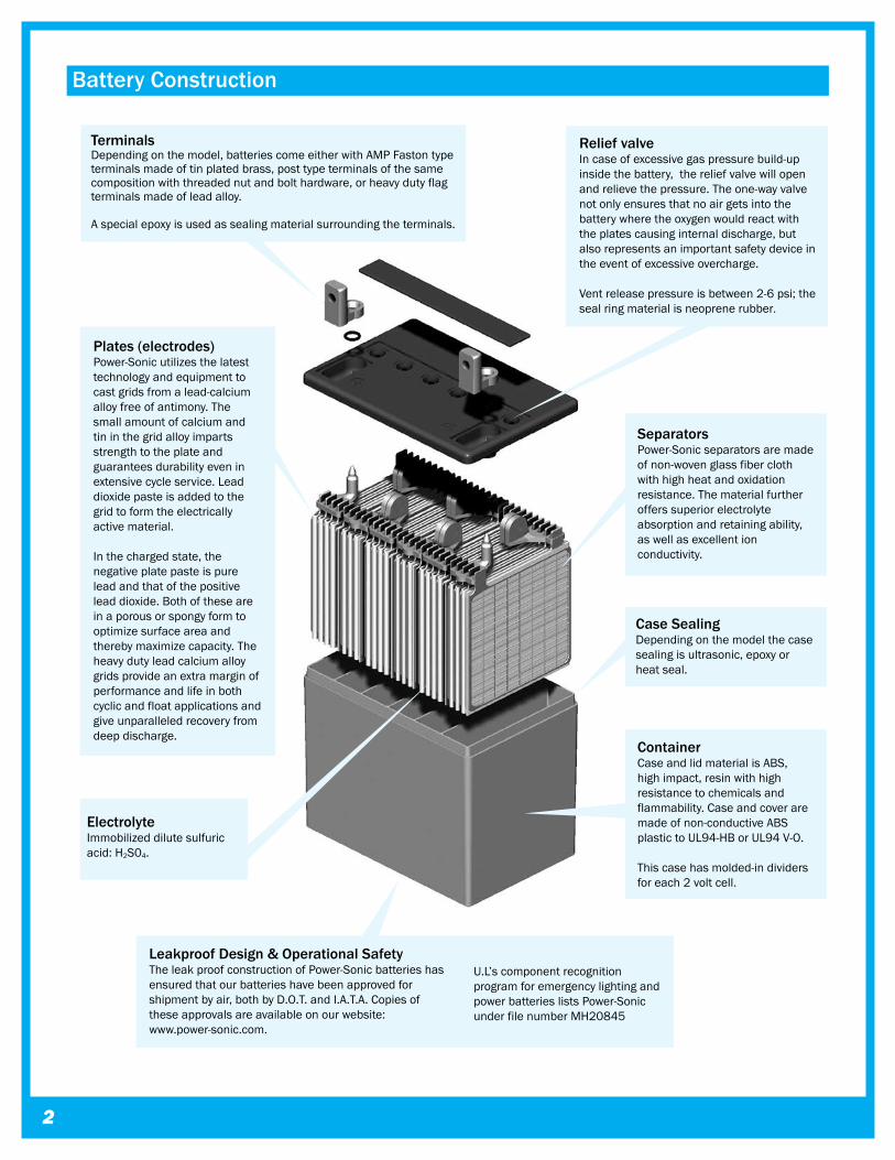
Relief valveIn case of excessive gas pressure build-up inside the battery, the relief valve will open and relieve the pressure. The one-way valve not only ensures that no air gets into the battery where the oxygen would react with the plates causing internal discharge, but also represents an important safety device in the event of excessive overcharge.
Vent release pressure is between 2-6 psi; the seal ring material is neoprene rubber.
TerminalsDepending on the model, batteries come either with AMP Faston type terminals made of tin plated brass, post type terminals of the same composition with threaded nut and bolt hardware, or heavy duty flag terminals made of lead alloy.
A special epoxy is used as sealing material surrounding the terminals.
ElectrolyteImmobilized dilute sulfuric acid: H2S04.
SeparatorsPower-Sonic separators are made of non-woven glass fiber cloth with high heat and oxidation resistance. The material further offers superior electrolyte absorption and retaining ability, as well as excellent ion conductivity.
Plates (electrodes)Power-Sonic utilizes the latest technology and equipment to cast grids from a lead-calcium alloy free of antimony. The small amount of calcium and tin in the grid alloy imparts strength to the plate and guarantees durability even in extensive cycle service. Lead dioxide paste is added to the grid to form the electrically active material.
In the charged state, the negative plate paste is pure lead and that of the positive lead dioxide. Both of these are in a porous or spongy form to optimize surface area and thereby maximize capacity. The heavy duty lead calcium alloy grids provide an extra margin of performance and life in both cyclic and float applications and give unparalleled recovery from deep discharge.
Leakproof Design & Operational SafetyThe leak proof construction of Power-Sonic batteries has ensured that our batteries have been approved for shipment by air, both by D.O.T. and I.A.T.A. Copies of these approvals are available on our website: www.power-sonic.com.
U.L’s component recognition program for emergency lighting and power batteries lists Power-Sonic under file number MH20845
Case SealingDepending on the model the case sealing is ultrasonic, epoxy or heat seal.
ContainerCase and lid material is ABS, high impact, resin with high resistance to chemicals and flammability. Case and cover are made of non-conductive ABS plastic to UL94-HB or UL94 V-O.
This case has molded-in dividers for each 2 volt cell.
POWER-SONIC Rechargeable Batteries �
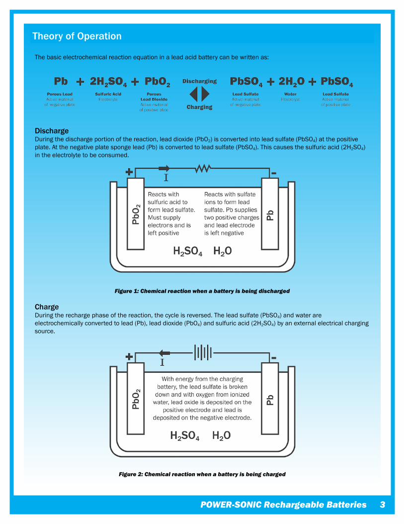
DischargeDuringthedischargeportionofthereaction,leaddioxide(PbO2)isconvertedintoleadsulfate(PbSO4)atthepositiveplate.Atthenegativeplatespongelead(Pb)isconvertedtoleadsulfate(PbSO4).Thiscausesthesulfuricacid(2H2SO4)intheelectrolytetobeconsumed.
Figure �: Chemical reaction when a battery is being discharged
ChargeDuringtherechargephaseofthereaction,thecycleisreversed.Theleadsulfate(PbSO4)andwaterareelectrochemicallyconvertedtolead(Pb),leaddioxide(PbO4)andsulfuricacid(2H2SO4)byanexternalelectricalchargingsource.
Figure �: Chemical reaction when a battery is being charged
Theory of Operation
Thebasicelectrochemicalreactionequationinaleadacidbatterycanbewrittenas:
�
Oxygen Recombination Toproduceatrulymaintenance-freebattery,itisnecessarythatgasesgeneratedduringoverchargearerecombinedinaso-called“oxygencycle”.Shouldoxygenandhydrogenescape,agradualdryingoutwouldoccur,eventuallyaffectingcapacityandbatterylife.
Duringcharge,oxygenisgeneratedatthepositiveandreactswithandpartiallydischargesthespongeleadofthenegative.Aschargingcontinuestheoxygenrecombineswiththehydrogenbeinggeneratedbythenegative,formingwater.Thewatercontentoftheelectrolytethusremainsunchangedunlessthechargingrateistoohigh.
Incaseofrapidgenerationofoxygenexceedingtheabsorbingcapacityofthenegativeplate,thepressurereliefvalvewillopentoreleaseexcessivegas.
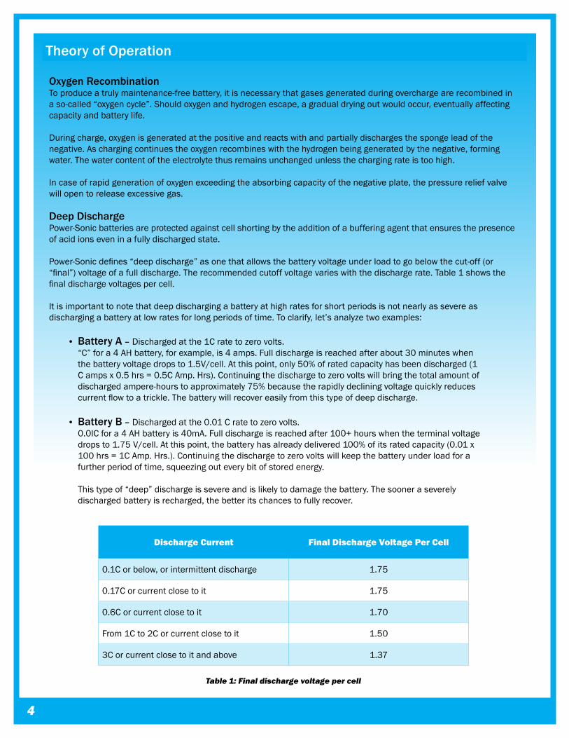
Deep DischargePower-Sonicbatteriesareprotectedagainstcellshortingbytheadditionofabufferingagentthatensuresthepresenceofacidionseveninafullydischargedstate.Power-Sonicdefines“deepdischarge”asonethatallowsthebatteryvoltageunderloadtogobelowthecut-off(or“final”)voltageofafulldischarge.Therecommendedcutoffvoltagevarieswiththedischargerate.Table1showsthefinaldischargevoltagespercell.
Itisimportanttonotethatdeepdischargingabatteryathighratesforshortperiodsisnotnearlyassevereasdischargingabatteryatlowratesforlongperiodsoftime.Toclarify,let’sanalyzetwoexamples:
• Battery A – Dischargedatthe1Cratetozerovolts.“C”fora4AHbattery,forexample,is4amps.Fulldischargeisreachedafterabout30minuteswhenthebatteryvoltagedropsto1.5V/cell.Atthispoint,only50%ofratedcapacityhasbeendischarged(1Campsx0.5hrs=0.5CAmp.Hrs).Continuingthedischargetozerovoltswillbringthetotalamountofdischargedampere-hourstoapproximately75%becausetherapidlydecliningvoltagequicklyreducescurrentflowtoatrickle.Thebatterywillrecovereasilyfromthistypeofdeepdischarge.
• Battery B – Dischargedatthe0.01Cratetozerovolts.0.0ICfora4AHbatteryis40mA.Fulldischargeisreachedafter100+hourswhentheterminalvoltagedropsto1.75V/cell.Atthispoint,thebatteryhasalreadydelivered100%ofitsratedcapacity(0.01x100hrs=1CAmp.Hrs.).Continuingthedischargetozerovoltswillkeepthebatteryunderloadforafurtherperiodoftime,squeezingouteverybitofstoredenergy.Thistypeof“deep”dischargeissevereandislikelytodamagethebattery.Thesooneraseverelydischargedbatteryisrecharged,thebetteritschancestofullyrecover.
Theory of Operation
Discharge Current Final Discharge Voltage Per Cell
0.1Corbelow,orintermittentdischarge 1.75
0.17Corcurrentclosetoit 1.75
0.6Corcurrentclosetoit 1.70
From1Cto2Corcurrentclosetoit 1.50
3Corcurrentclosetoitandabove 1.37
Table �: Final discharge voltage per cell
POWER-SONIC Rechargeable Batteries �
Capacity
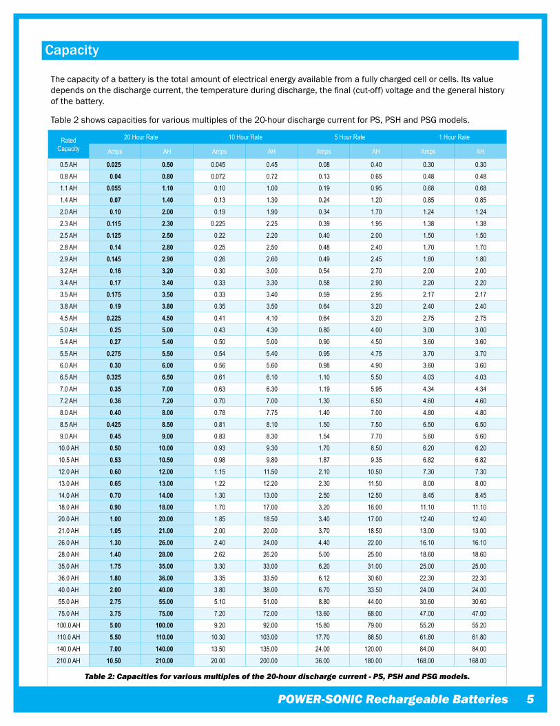
Thecapacityofabatteryisthetotalamountofelectricalenergyavailablefromafullychargedcellorcells.Itsvaluedependsonthedischargecurrent,thetemperatureduringdischarge,thefinal(cut-off)voltageandthegeneralhistoryofthebattery.
Table2showscapacitiesforvariousmultiplesofthe20-hourdischargecurrentforPS,PSHandPSGmodels.
Rated Capacity
20 Hour Rate 10 Hour Rate 5 Hour Rate 1 Hour Rate
Amps AH Amps AH Amps AH Amps AH
0.5 AH 0.025 0.50 0.045 0.45 0.08 0.40 0.30 0.300.8 AH 0.04 0.80 0.072 0.72 0.13 0.65 0.48 0.481.1 AH 0.055 1.10 0.10 1.00 0.19 0.95 0.68 0.681.4 AH 0.07 1.40 0.13 1.30 0.24 1.20 0.85 0.852.0 AH 0.10 2.00 0.19 1.90 0.34 1.70 1.24 1.242.3 AH 0.115 2.30 0.225 2.25 0.39 1.95 1.38 1.382.5 AH 0.125 2.50 0.22 2.20 0.40 2.00 1.50 1.502.8 AH 0.14 2.80 0.25 2.50 0.48 2.40 1.70 1.702.9 AH 0.145 2.90 0.26 2.60 0.49 2.45 1.80 1.803.2 AH 0.16 3.20 0.30 3.00 0.54 2.70 2.00 2.003.4 AH 0.17 3.40 0.33 3.30 0.58 2.90 2.20 2.203.5 AH 0.175 3.50 0.33 3.40 0.59 2.95 2.17 2.173.8 AH 0.19 3.80 0.35 3.50 0.64 3.20 2.40 2.404.5 AH 0.225 4.50 0.41 4.10 0.64 3.20 2.75 2.755.0 AH 0.25 5.00 0.43 4.30 0.80 4.00 3.00 3.005.4 AH 0.27 5.40 0.50 5.00 0.90 4.50 3.60 3.605.5 AH 0.275 5.50 0.54 5.40 0.95 4.75 3.70 3.706.0 AH 0.30 6.00 0.56 5.60 0.98 4.90 3.60 3.606.5 AH 0.325 6.50 0.61 6.10 1.10 5.50 4.03 4.037.0 AH 0.35 7.00 0.63 6.30 1.19 5.95 4.34 4.347.2 AH 0.36 7.20 0.70 7.00 1.30 6.50 4.60 4.608.0 AH 0.40 8.00 0.78 7.75 1.40 7.00 4.80 4.808.5 AH 0.425 8.50 0.81 8.10 1.50 7.50 6.50 6.509.0 AH 0.45 9.00 0.83 8.30 1.54 7.70 5.60 5.60
10.0 AH 0.50 10.00 0.93 9.30 1.70 8.50 6.20 6.2010.5 AH 0.53 10.50 0.98 9.80 1.87 9.35 6.82 6.8212.0 AH 0.60 12.00 1.15 11.50 2.10 10.50 7.30 7.3013.0 AH 0.65 13.00 1.22 12.20 2.30 11.50 8.00 8.0014.0 AH 0.70 14.00 1.30 13.00 2.50 12.50 8.45 8.4518.0 AH 0.90 18.00 1.70 17.00 3.20 16.00 11.10 11.1020.0 AH 1.00 20.00 1.85 18.50 3.40 17.00 12.40 12.4021.0 AH 1.05 21.00 2.00 20.00 3.70 18.50 13.00 13.0026.0 AH 1.30 26.00 2.40 24.00 4.40 22.00 16.10 16.1028.0 AH 1.40 28.00 2.62 26.20 5.00 25.00 18.60 18.6035.0 AH 1.75 35.00 3.30 33.00 6.20 31.00 25.00 25.0036.0 AH 1.80 36.00 3.35 33.50 6.12 30.60 22.30 22.3040.0 AH 2.00 40.00 3.80 38.00 6.70 33.50 24.00 24.0055.0 AH 2.75 55.00 5.10 51.00 8.80 44.00 30.60 30.6075.0 AH 3.75 75.00 7.20 72.00 13.60 68.00 47.00 47.00
100.0 AH 5.00 100.00 9.20 92.00 15.80 79.00 55.20 55.20110.0 AH 5.50 110.00 10.30 103.00 17.70 88.50 61.80 61.80140.0 AH 7.00 140.00 13.50 135.00 24.00 120.00 84.00 84.00210.0 AH 10.50 210.00 20.00 200.00 36.00 180.00 168.00 168.00
Table �: Capacities for various multiples of the �0-hour discharge current - PS, PSH and PSG models.
Capacity
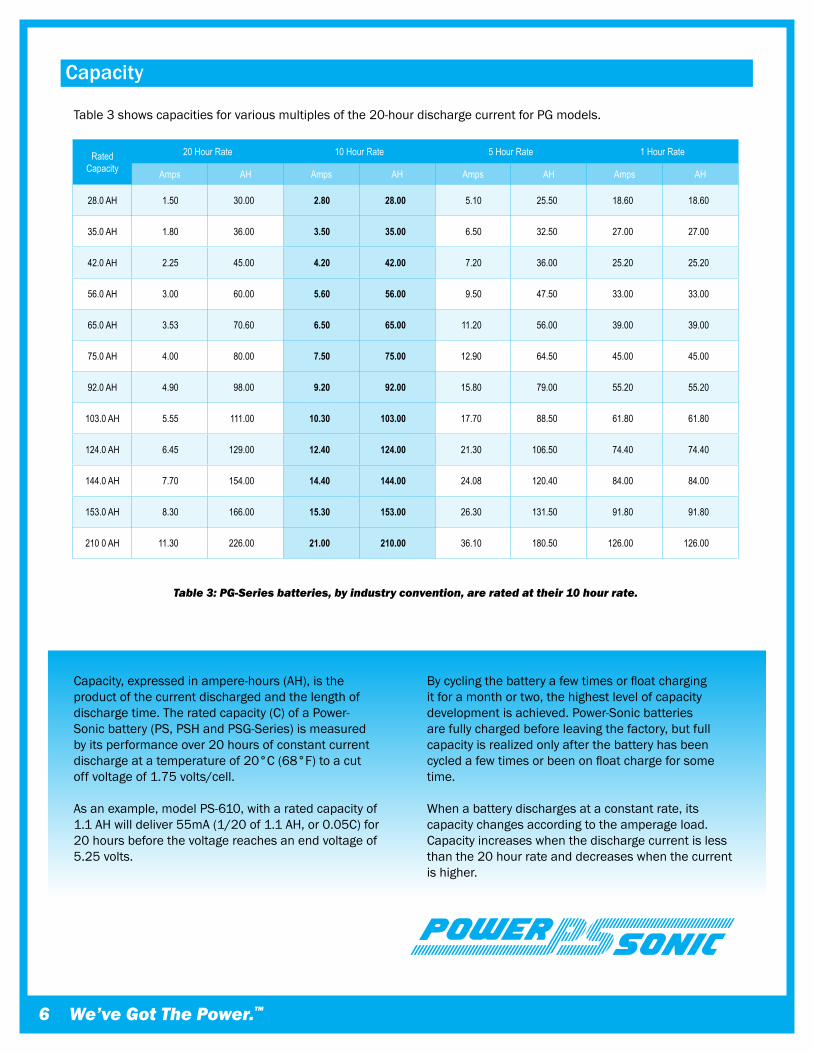
Capacity,expressedinampere-hours(AH),istheproductofthecurrentdischargedandthelengthofdischargetime.Theratedcapacity(C)ofaPower-Sonicbattery(PS,PSHandPSG-Series)ismeasuredbyitsperformanceover20hoursofconstantcurrentdischargeatatemperatureof20°C(68°F)toacutoffvoltageof1.75volts/cell.
Asanexample,modelPS-610,witharatedcapacityof1.1AHwilldeliver55mA(1/20of1.1AH,or0.05C)for20hoursbeforethevoltagereachesanendvoltageof5.25volts.
Bycyclingthebatteryafewtimesorfloatchargingitforamonthortwo,thehighestlevelofcapacitydevelopmentisachieved.Power-Sonicbatteriesarefullychargedbeforeleavingthefactory,butfullcapacityisrealizedonlyafterthebatteryhasbeencycledafewtimesorbeenonfloatchargeforsometime.
Whenabatterydischargesataconstantrate,itscapacitychangesaccordingtotheamperageload.Capacityincreaseswhenthedischargecurrentislessthanthe20hourrateanddecreaseswhenthecurrentishigher.
Rated Capacity
20 Hour Rate 10 Hour Rate 5 Hour Rate 1 Hour Rate
Amps AH Amps AH Amps AH Amps AH
28.0 AH 1.50 30.00 2.80 28.00 5.10 25.50 18.60 18.60
35.0 AH 1.80 36.00 3.50 35.00 6.50 32.50 27.00 27.00
42.0 AH 2.25 45.00 4.20 42.00 7.20 36.00 25.20 25.20
56.0 AH 3.00 60.00 5.60 56.00 9.50 47.50 33.00 33.00
65.0 AH 3.53 70.60 6.50 65.00 11.20 56.00 39.00 39.00
75.0 AH 4.00 80.00 7.50 75.00 12.90 64.50 45.00 45.00
92.0 AH 4.90 98.00 9.20 92.00 15.80 79.00 55.20 55.20
103.0 AH 5.55 111.00 10.30 103.00 17.70 88.50 61.80 61.80
124.0 AH 6.45 129.00 12.40 124.00 21.30 106.50 74.40 74.40
144.0 AH 7.70 154.00 14.40 144.00 24.08 120.40 84.00 84.00
153.0 AH 8.30 166.00 15.30 153.00 26.30 131.50 91.80 91.80
210 0 AH 11.30 226.00 21.00 210.00 36.10 180.50 126.00 126.00
Table �: PG-Series batteries, by industry convention, are rated at their �0 hour rate.
Table3showscapacitiesforvariousmultiplesofthe20-hourdischargecurrentforPGmodels.
� We’ve Got The Power.™
POWER-SONIC Rechargeable Batteries �
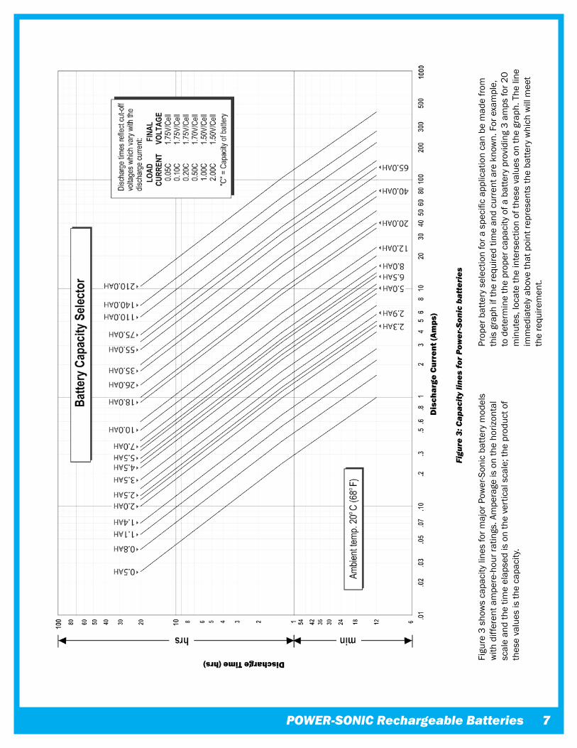
Figu
re3
sho
ws
capa
city
line
sfo
rmaj
orP
ower
-Son
icb
atte
rym
odel
sw
ithd
iffer
enta
mpe
re-h
ourr
atin
gs.A
mpe
rage
iso
nth
eho
rizon
tal
scal
ean
dth
etim
eel
apse
dis
on
the
vert
ical
sca
le;t
hep
rodu
cto
fth
ese
valu
esis
the
capa
city
.
Properbatteryselectionforaspecificapplicationcanbemadefrom
this
gra
phif
the
requ
ired
time
and
curr
enta
rek
now
n.F
ore
xam
ple,
to
det
erm
ine
the
prop
erc
apac
ityo
fab
atte
ryp
rovi
ding
3a
mps
for2
0m
inut
es,l
ocat
eth
ein
ters
ectio
nof
thes
eva
lues
on
the
grap
h.T
heli
ne
imm
edia
tely
abo
veth
atp
oint
repr
esen
tsth
eba
ttery
whi
chw
illm
eet
the
requ
irem
ent.
Figu
re �
: Cap
acity
line
s fo
r Pow
er-S
onic
bat
teri
es
Dis
char
ge C
urre
nt (A
mps
)
Discharge Time (hrs)
�
Performance Data
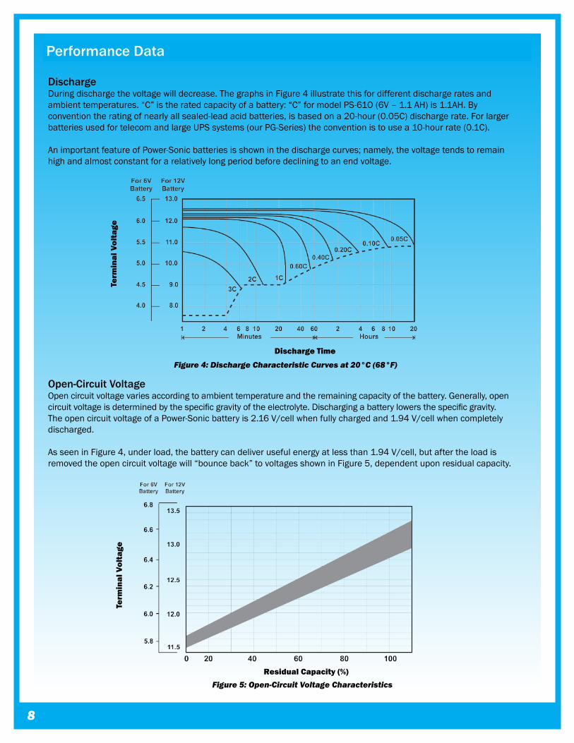
DischargeDuringdischargethevoltagewilldecrease.ThegraphsinFigure4illustratethisfordifferentdischargeratesandambienttemperatures.“C”istheratedcapacityofabattery:“C”formodelPS-61O(6V–1.1AH)is1.1AH.Byconventiontheratingofnearlyallsealed-leadacidbatteries,isbasedona20-hour(0.05C)dischargerate.ForlargerbatteriesusedfortelecomandlargeUPSsystems(ourPG-Series)theconventionistousea10-hourrate(0.1C).
AnimportantfeatureofPower-Sonicbatteriesisshowninthedischargecurves;namely,thevoltagetendstoremainhighandalmostconstantforarelativelylongperiodbeforedecliningtoanendvoltage.
Open-Circuit VoltageOpencircuitvoltagevariesaccordingtoambienttemperatureandtheremainingcapacityofthebattery.Generally,opencircuitvoltageisdeterminedbythespecificgravityoftheelectrolyte.Dischargingabatterylowersthespecificgravity.TheopencircuitvoltageofaPower-Sonicbatteryis2.16V/cellwhenfullychargedand1.94V/cellwhencompletelydischarged.
AsseeninFigure4,underload,thebatterycandeliverusefulenergyatlessthan1.94V/cell,butaftertheloadisremovedtheopencircuitvoltagewill“bounceback”tovoltagesshowninFigure5,dependentuponresidualcapacity.
Figure �: Discharge Characteristic Curves at �0°C (��°F)
Figure �: Open-Circuit Voltage Characteristics
Discharge Time
Term
inal
Vol
tage
Term
inal
Vol
tage
Residual Capacity (%)
POWER-SONIC Rechargeable Batteries �
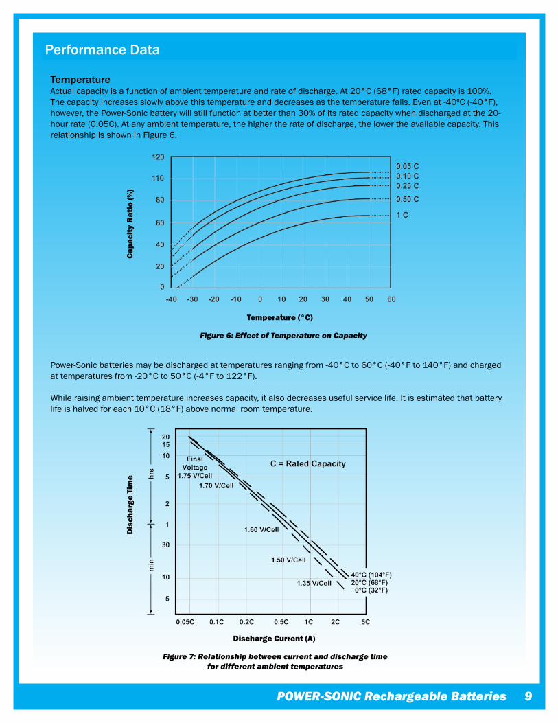
TemperatureActualcapacityisafunctionofambienttemperatureandrateofdischarge.At20°C(68°F)ratedcapacityis100%.Thecapacityincreasesslowlyabovethistemperatureanddecreasesasthetemperaturefalls.Evenat-40ºC(-40°F),however,thePower-Sonicbatterywillstillfunctionatbetterthan30%ofitsratedcapacitywhendischargedatthe20-hourrate(0.05C).Atanyambienttemperature,thehighertherateofdischarge,thelowertheavailablecapacity.ThisrelationshipisshowninFigure6.
Power-Sonicbatteriesmaybedischargedattemperaturesrangingfrom-40°Cto60°C(-40°Fto140°F)andchargedattemperaturesfrom-20°Cto50°C(-4°Fto122°F).
Whileraisingambienttemperatureincreasescapacity,italsodecreasesusefulservicelife.Itisestimatedthatbatterylifeishalvedforeach10°C(18°F)abovenormalroomtemperature.
Performance Data
Figure �: Relationship between current and discharge time for different ambient temperatures
Figure �: Effect of Temperature on Capacity
Capa
city
Rat
io (%
)
Temperature (°C)
Dis
char
ge T
ime
Discharge Current (A)
�0
Performance Data
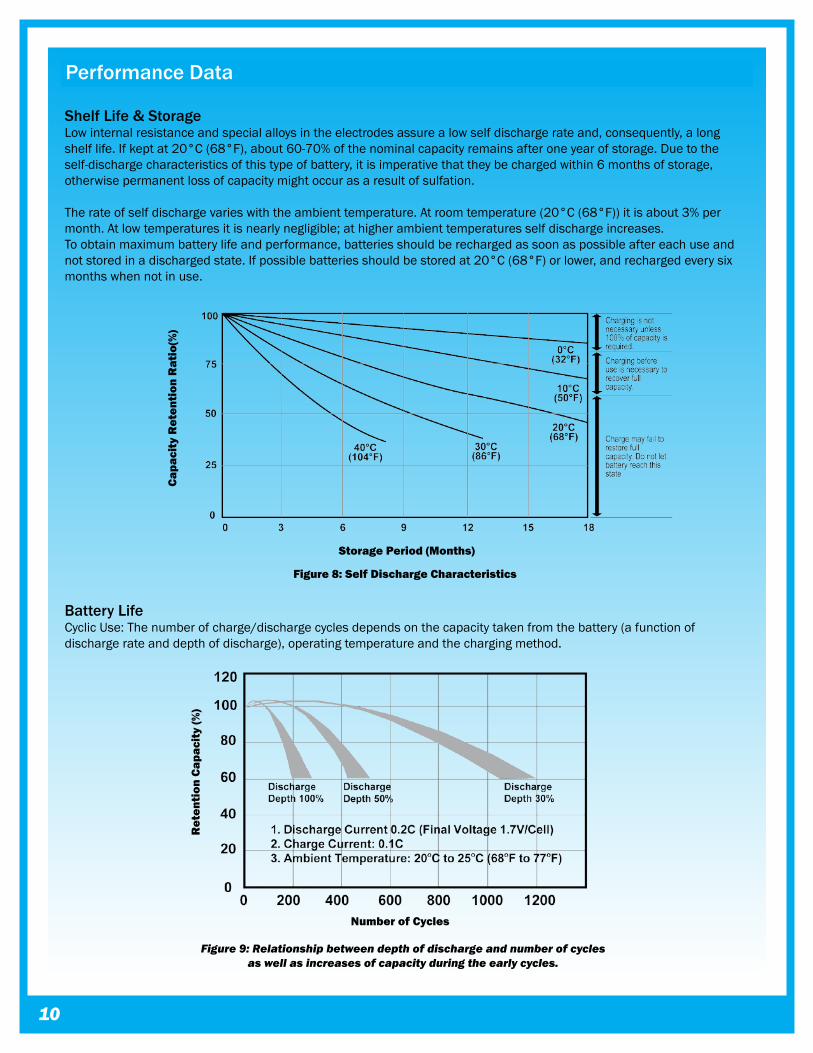
Shelf Life & StorageLowinternalresistanceandspecialalloysintheelectrodesassurealowselfdischargerateand,consequently,alongshelflife.Ifkeptat20°C(68°F),about60-70%ofthenominalcapacityremainsafteroneyearofstorage.Duetotheself-dischargecharacteristicsofthistypeofbattery,itisimperativethattheybechargedwithin6monthsofstorage,otherwisepermanentlossofcapacitymightoccurasaresultofsulfation.
Therateofselfdischargevarieswiththeambienttemperature.Atroomtemperature(20°C(68°F))itisabout3%permonth.Atlowtemperaturesitisnearlynegligible;athigherambienttemperaturesselfdischargeincreases.Toobtainmaximumbatterylifeandperformance,batteriesshouldberechargedassoonaspossibleaftereachuseandnotstoredinadischargedstate.Ifpossiblebatteriesshouldbestoredat20°C(68°F)orlower,andrechargedeverysixmonthswhennotinuse.
Battery LifeCyclicUse:Thenumberofcharge/dischargecyclesdependsonthecapacitytakenfromthebattery(afunctionofdischargerateanddepthofdischarge),operatingtemperatureandthechargingmethod.
Figure 8: Self Discharge Characteristics
Figure �: Relationship between depth of discharge and number of cycles as well as increases of capacity during the early cycles.
Capa
city
Ret
enti
on R
atio
(%)
Storage Period (Months)
Ret
enti
on C
apac
ity
(%)
Number of Cycles
POWER-SONIC Rechargeable Batteries ��
Performance Data
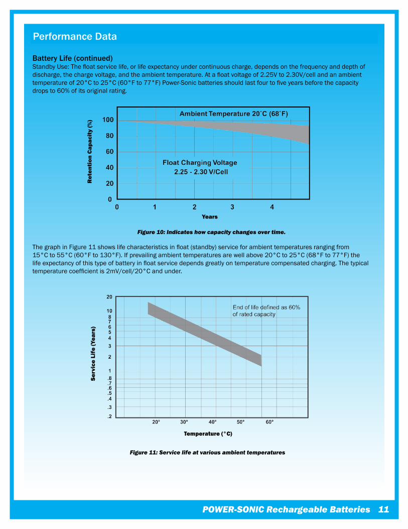
Battery Life (continued)StandbyUse:Thefloatservicelife,orlifeexpectancyundercontinuouscharge,dependsonthefrequencyanddepthofdischarge,thechargevoltage,andtheambienttemperature.Atafloatvoltageof2.25Vto2.30V/cellandanambienttemperatureof20°Cto25°C(60°Fto77°F)Power-Sonicbatteriesshouldlastfourtofiveyearsbeforethecapacitydropsto60%ofitsoriginalrating.
ThegraphinFigure11showslifecharacteristicsinfloat(standby)serviceforambienttemperaturesrangingfrom15°Cto55°C(60°Fto130°F).Ifprevailingambienttemperaturesarewellabove20°Cto25°C(68°Fto77°F)thelifeexpectancyofthistypeofbatteryinfloatservicedependsgreatlyontemperaturecompensatedcharging.Thetypicaltemperaturecoefficientis2mV/cell/20°Candunder.
Figure �0: Indicates how capacity changes over time.
Figure ��: Service life at various ambient temperatures
Ret
enti
on C
apac
ity
(%)
Years
Serv
ice
Life
(Yea
rs)
Temperature (°C)
��
Performance Data
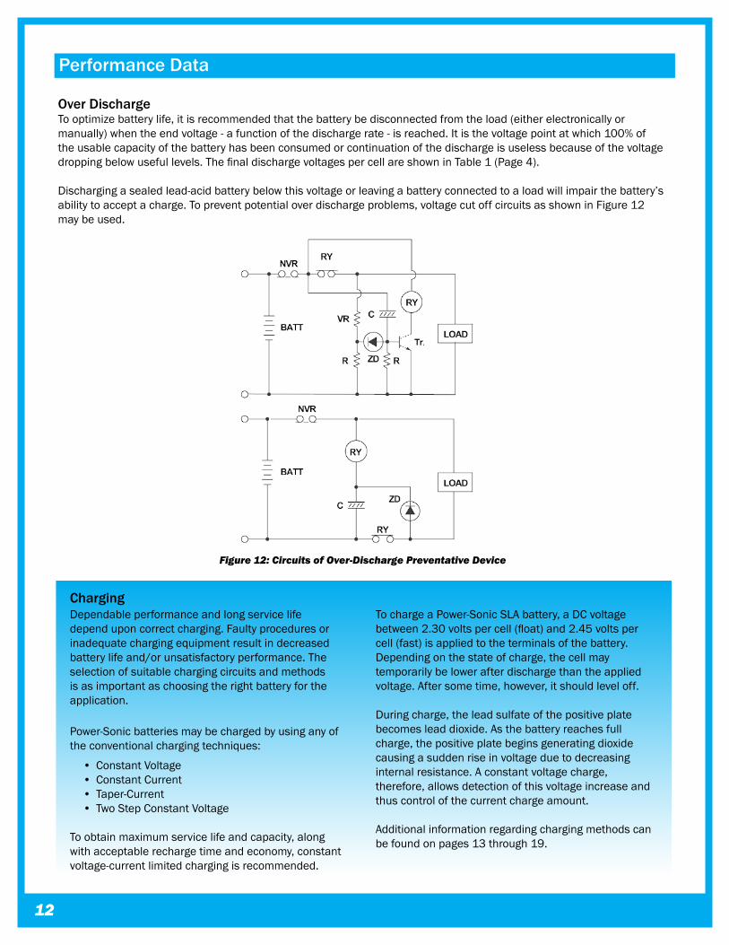
Over DischargeTooptimizebatterylife,itisrecommendedthatthebatterybedisconnectedfromtheload(eitherelectronicallyormanually)whentheendvoltage-afunctionofthedischargerate-isreached.Itisthevoltagepointatwhich100%oftheusablecapacityofthebatteryhasbeenconsumedorcontinuationofthedischargeisuselessbecauseofthevoltagedroppingbelowusefullevels.ThefinaldischargevoltagespercellareshowninTable1(Page4).
Dischargingasealedlead-acidbatterybelowthisvoltageorleavingabatteryconnectedtoaloadwillimpairthebattery’sabilitytoacceptacharge.Topreventpotentialoverdischargeproblems,voltagecutoffcircuitsasshowninFigure12maybeused.
Figure ��: Circuits of Over-Discharge Preventative Device
ChargingDependableperformanceandlongservicelifedependuponcorrectcharging.Faultyproceduresorinadequatechargingequipmentresultindecreasedbatterylifeand/orunsatisfactoryperformance.Theselectionofsuitablechargingcircuitsandmethodsisasimportantaschoosingtherightbatteryfortheapplication.
Power-Sonicbatteriesmaybechargedbyusinganyoftheconventionalchargingtechniques:
• ConstantVoltage • ConstantCurrent • Taper-Current • TwoStepConstantVoltage
Toobtainmaximumservicelifeandcapacity,alongwithacceptablerechargetimeandeconomy,constantvoltage-currentlimitedchargingisrecommended.
TochargeaPower-SonicSLAbattery,aDCvoltagebetween2.30voltspercell(float)and2.45voltspercell(fast)isappliedtotheterminalsofthebattery.Dependingonthestateofcharge,thecellmaytemporarilybelowerafterdischargethantheappliedvoltage.Aftersometime,however,itshouldleveloff.
Duringcharge,theleadsulfateofthepositiveplatebecomesleaddioxide.Asthebatteryreachesfullcharge,thepositiveplatebeginsgeneratingdioxidecausingasuddenriseinvoltageduetodecreasinginternalresistance.Aconstantvoltagecharge,therefore,allowsdetectionofthisvoltageincreaseandthuscontrolofthecurrentchargeamount.
Additionalinformationregardingchargingmethodscanbefoundonpages13through19.
POWER-SONIC Rechargeable Batteries ��
Charging
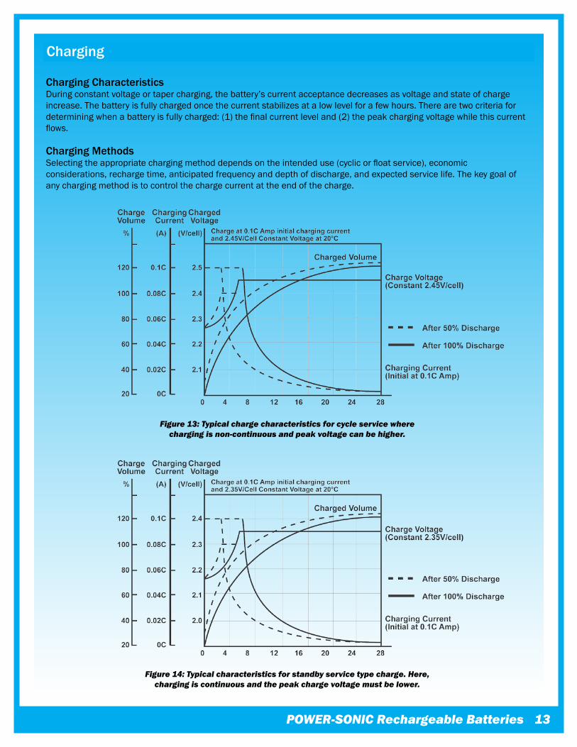
Charging CharacteristicsDuringconstantvoltageortapercharging,thebattery’scurrentacceptancedecreasesasvoltageandstateofchargeincrease.Thebatteryisfullychargedoncethecurrentstabilizesatalowlevelforafewhours.Therearetwocriteriafordeterminingwhenabatteryisfullycharged:(1)thefinalcurrentleveland(2)thepeakchargingvoltagewhilethiscurrentflows.
Charging MethodsSelectingtheappropriatechargingmethoddependsontheintendeduse(cyclicorfloatservice),economicconsiderations,rechargetime,anticipatedfrequencyanddepthofdischarge,andexpectedservicelife.Thekeygoalofanychargingmethodistocontrolthechargecurrentattheendofthecharge.
Figure ��: Typical charge characteristics for cycle service where charging is non-continuous and peak voltage can be higher.
Figure ��: Typical characteristics for standby service type charge. Here, charging is continuous and the peak charge voltage must be lower.
��
Charging
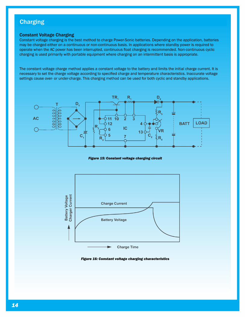
Constant Voltage Charging ConstantvoltagechargingisthebestmethodtochargePower-Sonicbatteries.Dependingontheapplication,batteriesmaybechargedeitheronacontinuousornon-continuousbasis.InapplicationswherestandbypowerisrequiredtooperatewhentheACpowerhasbeeninterrupted,continuousfloatchargingisrecommended.Non-continuouscyclicchargingisusedprimarilywithportableequipmentwherechargingonanintermittentbasisisappropriate.
Theconstantvoltagechargemethodappliesaconstantvoltagetothebatteryandlimitstheinitialchargecurrent.Itisnecessarytosetthechargevoltageaccordingtospecifiedchargeandtemperaturecharacteristics.Inaccuratevoltagesettingscauseover-orunder-charge.Thischargingmethodcanbeusedforbothcyclicandstandbyapplications.
Figure ��: Constant voltage charging circuit
Figure ��: Constant voltage charging characteristics
POWER-SONIC Rechargeable Batteries ��
Charging
Constant Current Charging Constantcurrentchargingissuitedforapplicationswheredischargedampere-hoursoftheprecedingdischargecycleareknown.Chargetimeandchargequantitycaneasilybecalculated,howeveranexpensivecircuitisnecessarytoobtainahighlyaccurateconstantcurrent.Monitoringofchargevoltageorlimitingofchargetimeisnecessarytoavoidexcessiveovercharge.
Whilethischargingmethodisveryeffectiveforrecoveringthecapacityofabatterythathasbeenstoredforanextendedperiodoftime,orforoccasionaloverchargingtoequalizecellcapacities,itlacksspecificpropertiesrequiredintoday’selectronicenvironment.
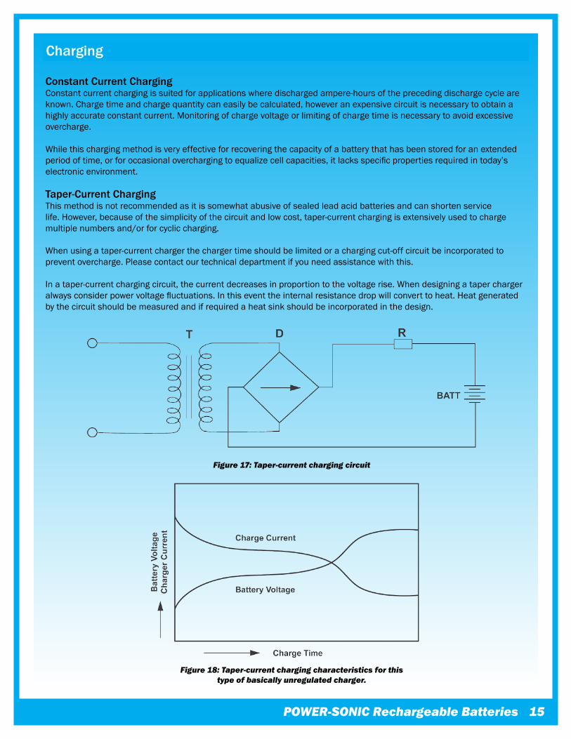
Taper-Current Charging Thismethodisnotrecommendedasitissomewhatabusiveofsealedleadacidbatteriesandcanshortenservicelife.However,becauseofthesimplicityofthecircuitandlowcost,taper-currentchargingisextensivelyusedtochargemultiplenumbersand/orforcycliccharging.
Whenusingataper-currentchargerthechargertimeshouldbelimitedorachargingcut-offcircuitbeincorporatedtopreventovercharge.Pleasecontactourtechnicaldepartmentifyouneedassistancewiththis.
Inataper-currentchargingcircuit,thecurrentdecreasesinproportiontothevoltagerise.Whendesigningataperchargeralwaysconsiderpowervoltagefluctuations.Inthiseventtheinternalresistancedropwillconverttoheat.Heatgeneratedbythecircuitshouldbemeasuredandifrequiredaheatsinkshouldbeincorporatedinthedesign.
Figure ��: Taper-current charging characteristics for this type of basically unregulated charger.
Figure ��: Taper-current charging circuit
��
Overcharging Asaresultoftoohighachargevoltageexcessivecurrentwillflowintothebattery,afterreachingfullcharge,causingdecompositionofwaterintheelectrolyteandprematureaging.
Athighratesofoverchargeabatterywillprogressivelyheatup.Asitgetshotter,itwillacceptmorecurrent,heatingupevenfurther.Thisiscalledthermalrunawayanditcandestroyabatteryinaslittleasafewhours.
Undercharging Iftoolowachargevoltageisapplied,thecurrentflowwillessentiallystopbeforethebatteryisfullycharged.Thisallowssomeoftheleadsulfatetoremainontheelectrodes,whichwilleventuallyreducecapacity.
Batterieswhicharestoredinadischargedstate,orleftontheshelffortoolong,mayinitiallyappeartobe“opencircuited”orwillacceptfarlesscurrentthannormal.Thisiscausedbyaphenomenoncalled“sulfation”.Whenthisoccurs,leavethechargerconnectedtothebattery.Usually,thebatterywillstarttoacceptincreasingamountsofcurrentuntilanormalcurrentlevelisreached.Ifthereisnoresponse,eventochargevoltagesaboverecommendedlevels,thebatterymayhavebeeninadischargedstatefortoolongtorecover.
Ifinanydoubt,orifconceptsofproperuseandcareareunclear,pleaseensurethatyoucontactPower-Sonic’stechnicaldepartment.
Charging for Cycle OperationCyclicapplicationsgenerallyrequirethatrechargingbedoneinarelativelyshorttime.Theinitialchargecurrent,however,mustnotexceed0.30xCamps.Justasbatteryvoltagedropsduringdischarge,itslowlyrisesduringcharge.Fullchargeisdeterminedbyvoltageandinflowingcurrent.When,atachargevoltageof2.45±0.05volts/cell,thecurrentacceptedbythebatterydropstolessthan0.01xCamps(1%ofratedcapacity),thebatteryisfullychargedandthechargershouldbedisconnectedorswitchedtoafloatvoltageof2.25to2.30volts/cell.Thevoltageshouldnotbeallowedtoriseabove2.45±0.05volts/cell.
Charging for Standby OperationStandbyapplicationsgenerallydonotrequirethatthebatterybechargedasfastorasfrequentlyasincycleoperation.However,thebatterymustbekeptconstantlychargedtoreplacetheenergythatisexpendedduetointernallossanddeteriorationofthebatteryitself.AlthoughtheselossesareverylowinPower-Sonicbatteries,theymustbereplacedattheratethebatteryselfdischarges;atthesametimethebatterymustnotbegivenmorethantheselossesoritwillbeovercharged.Toaccomplishthis,aconstantvoltagemethodofchargingcalled“floatcharging”isused.
Therecommendedconstantfloatvoltageis2.25-2.30voltspercell.Maintainingthisfloatvoltagewillallowthebatterytodefineitsowncurrentlevelandremainfullychargedwithouthavingtodisconnectthechargerfromthebattery.ThetricklecurrentforafullychargedbatteryfloatingattherecommendedchargevoltagewilltypicallyhoveraroundtheO.OO1Crate(1OmAfora10AHbattery,forexample.)
Thefloatchargerisbasicallyaconstantvoltagepowersupply.Asincyclechargers,caremustbeexercisednottoexceedtheinitialchargecurrentof0.30xCamperes.
Charging
Caution! Never charge or discharge a battery in a hermetically sealed enclosure. Batteries generate a mixture of gases internally. Given the right set of circumstances, such as extreme overcharging or shorting of the battery, these gases might vent into the enclosure and create the potential for an explosion when ignited by a spark.
POWER-SONIC Rechargeable Batteries ��
Charging
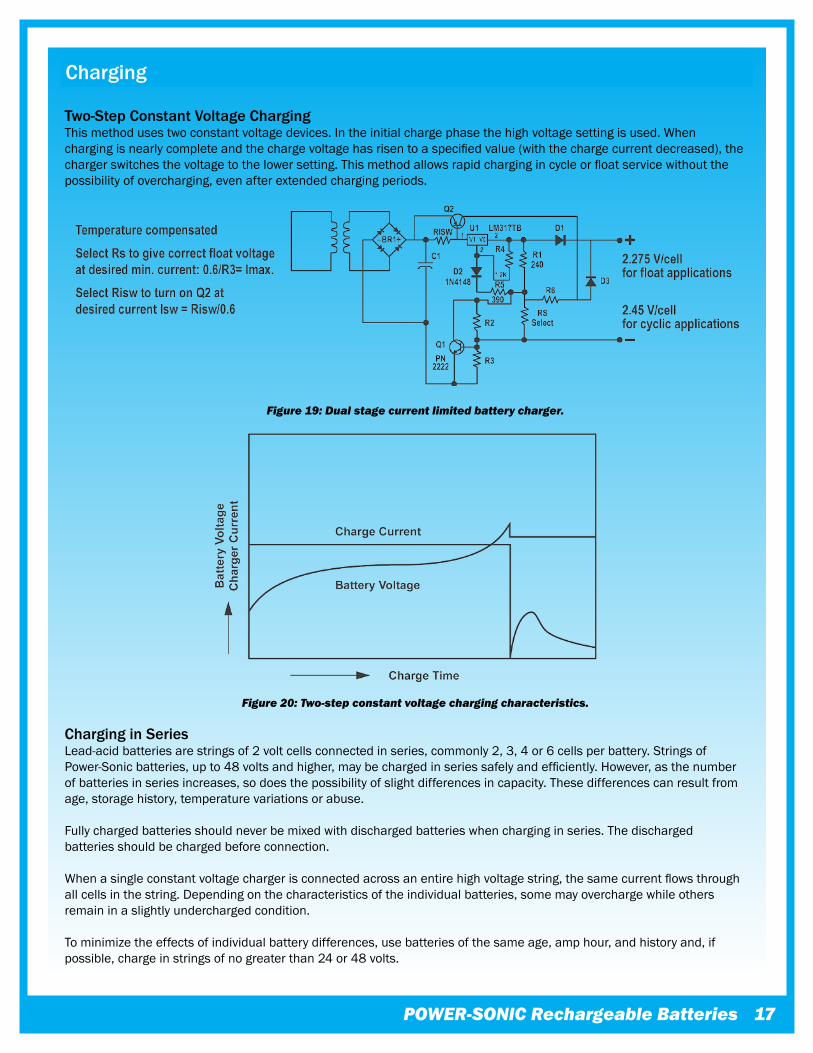
Two-Step Constant Voltage ChargingThismethodusestwoconstantvoltagedevices.Intheinitialchargephasethehighvoltagesettingisused.Whenchargingisnearlycompleteandthechargevoltagehasrisentoaspecifiedvalue(withthechargecurrentdecreased),thechargerswitchesthevoltagetothelowersetting.Thismethodallowsrapidchargingincycleorfloatservicewithoutthepossibilityofovercharging,evenafterextendedchargingperiods.
Charging in Series Lead-acidbatteriesarestringsof2voltcellsconnectedinseries,commonly2,3,4or6cellsperbattery.StringsofPower-Sonicbatteries,upto48voltsandhigher,maybechargedinseriessafelyandefficiently.However,asthenumberofbatteriesinseriesincreases,sodoesthepossibilityofslightdifferencesincapacity.Thesedifferencescanresultfromage,storagehistory,temperaturevariationsorabuse.
Fullychargedbatteriesshouldneverbemixedwithdischargedbatterieswhencharginginseries.Thedischargedbatteriesshouldbechargedbeforeconnection.
Whenasingleconstantvoltagechargerisconnectedacrossanentirehighvoltagestring,thesamecurrentflowsthroughallcellsinthestring.Dependingonthecharacteristicsoftheindividualbatteries,somemayoverchargewhileothersremaininaslightlyunderchargedcondition.
Tominimizetheeffectsofindividualbatterydifferences,usebatteriesofthesameage,amphour,andhistoryand,ifpossible,chargeinstringsofnogreaterthan24or48volts.
Figure ��: Dual stage current limited battery charger.
Figure �0: Two-step constant voltage charging characteristics.
��
Charging
Charging in Parallel Power-Sonicbatteriesmaybeusedinparallelwithoneormorebatteriesofequalvoltage.
Whenconnectedinparallel,thecurrentfromachargerwilltendtodividealmostequallybetweenthebatteries.Nospecialmatchingofbatteriesisrequired.Ifthebatteriesofunequalcapacityareconnectedinparallel,thecurrentwilltendtodividebetweenthebatteriesintheratioofcapacities(actually,internalresistances).
Whenchargingbatteriesinparallel,wheredifferentratiosofchargearetobeexpected,itisbesttomakeprovisionstoassurethatthecurrentswillnotvarytoomuchbetweenbatteries.
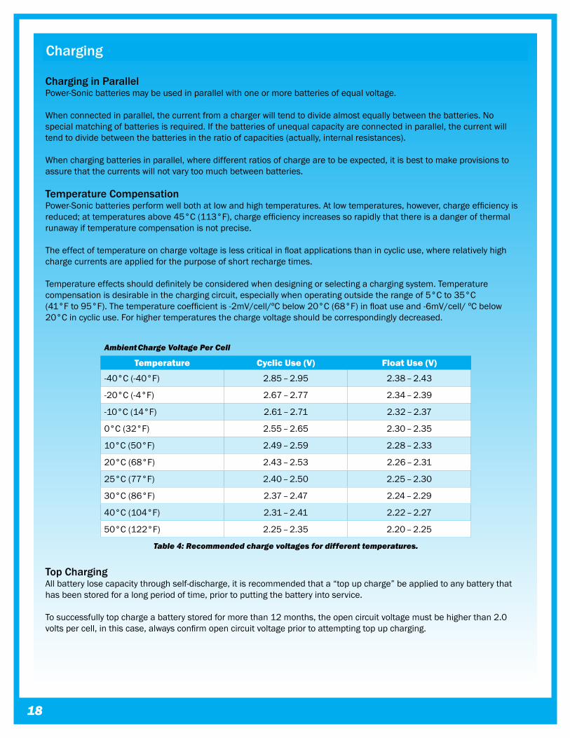
Temperature CompensationPower-Sonicbatteriesperformwellbothatlowandhightemperatures.Atlowtemperatures,however,chargeefficiencyisreduced;attemperaturesabove45°C(113°F),chargeefficiencyincreasessorapidlythatthereisadangerofthermalrunawayiftemperaturecompensationisnotprecise.
Theeffectoftemperatureonchargevoltageislesscriticalinfloatapplicationsthanincyclicuse,whererelativelyhighchargecurrentsareappliedforthepurposeofshortrechargetimes.
Temperatureeffectsshoulddefinitelybeconsideredwhendesigningorselectingachargingsystem.Temperaturecompensationisdesirableinthechargingcircuit,especiallywhenoperatingoutsidetherangeof5°Cto35°C(41°Fto95°F).Thetemperaturecoefficientis-2mV/cell/ºCbelow20°C(68°F)infloatuseand-6mV/cell/ºCbelow20°Cincyclicuse.Forhighertemperaturesthechargevoltageshouldbecorrespondinglydecreased.
Top ChargingAllbatterylosecapacitythroughself-discharge,itisrecommendedthata“topupcharge”beappliedtoanybatterythathasbeenstoredforalongperiodoftime,priortoputtingthebatteryintoservice.
Tosuccessfullytopchargeabatterystoredformorethan12months,theopencircuitvoltagemustbehigherthan2.0voltspercell,inthiscase,alwaysconfirmopencircuitvoltagepriortoattemptingtopupcharging.
Ambient Charge Voltage Per Cell
Temperature Cyclic Use (V) Float Use (V)
-40°C(-40°F) 2.85–2.95 2.38–2.43
-20°C(-4°F) 2.67–2.77 2.34–2.39
-10°C(14°F) 2.61–2.71 2.32–2.37
0°C(32°F) 2.55–2.65 2.30–2.35
10°C(50°F) 2.49–2.59 2.28–2.33
20°C(68°F) 2.43–2.53 2.26–2.31
25°C(77°F) 2.40–2.50 2.25–2.30
30°C(86°F) 2.37–2.47 2.24–2.29
40°C(104°F) 2.31–2.41 2.22–2.27
50°C(122°F) 2.25–2.35 2.20–2.25
Table �: Recommended charge voltages for different temperatures.
POWER-SONIC Rechargeable Batteries ��
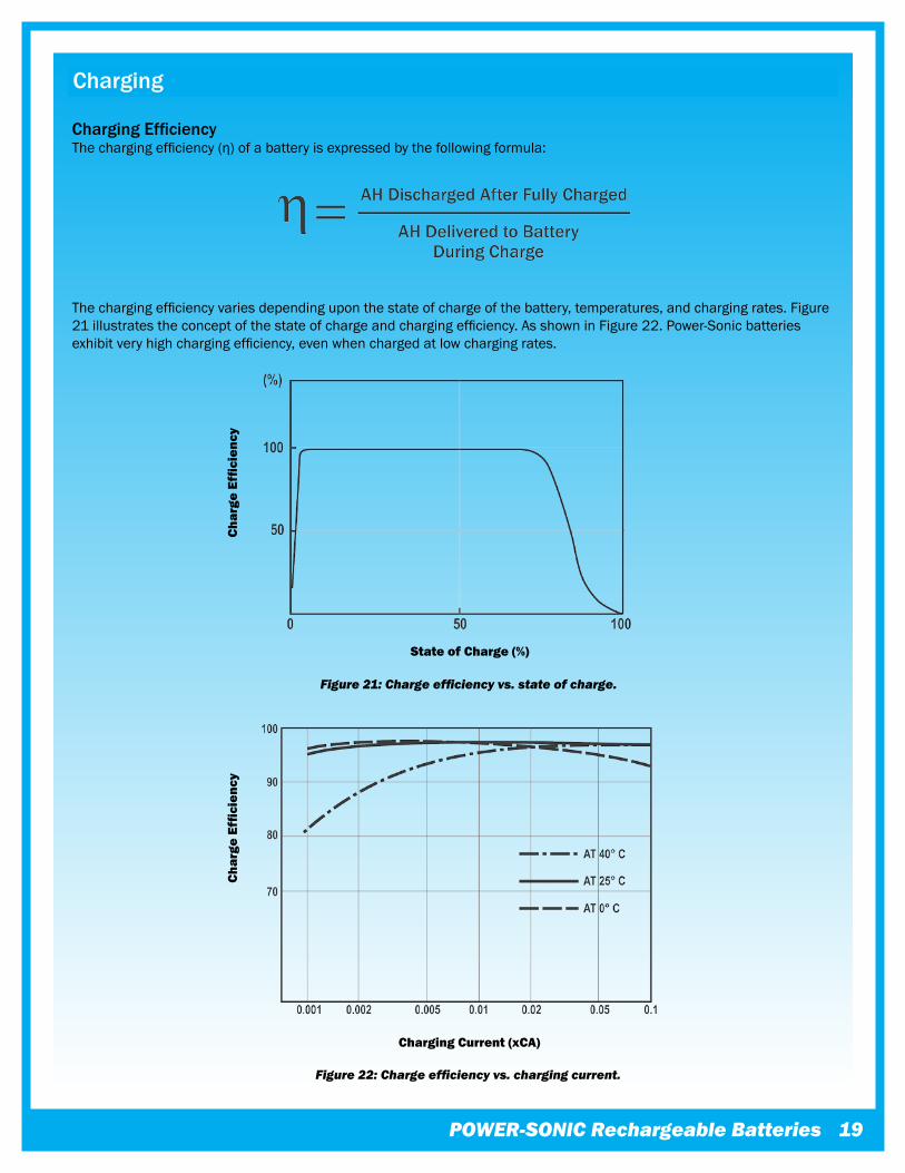
Charging EfficiencyThechargingefficiency(η)ofabatteryisexpressedbythefollowingformula:
Thechargingefficiencyvariesdependinguponthestateofchargeofthebattery,temperatures,andchargingrates.Figure21illustratestheconceptofthestateofchargeandchargingefficiency.AsshowninFigure22.Power-Sonicbatteriesexhibitveryhighchargingefficiency,evenwhenchargedatlowchargingrates.
Charging
Figure 21: Charge efficiency vs. state of charge.
Char
ge E
ffici
ency
State of Charge (%)
Figure 22: Charge efficiency vs. charging current.
Char
ge E
ffici
ency
Charging Current (xCA)
�0
Important Do’s and Don’ts
Power-Sonicrechargeablesealedlead-acidbatteriesaredesignedtoprovideyearsofdependableservice.Adherencetothefollowingguidelineswillensurethatbatterylifeismaximizedandoperationistrouble-free.
Material Safety Data Sheets (MSDS)
• Itisimportantthatyoufamiliarizeyourselfwiththesepriortohandling,installinganddisposingofallbatteries.IfthereareanyquestionsraisedfromthesepleasecontactPower-Sonic’stechnicaldepartment.
Handling
•Alwayswearinsulatedgloveswhenhandlingbatteries;especiallywhenconnectingseriesandparallelgroupsofbatteries.
•FollowallprecautionsasdescribedinourMaterialsSafetyDataSheets(MSDS).Thisinformationissubjecttochangedependingupongovernmentlegislation.Visitourwebsite:www.power-sonic.comforup-to-datecopiesofthese.
•Ifequipmentistobestoredforalongperiodoftimethebatteriesshouldbedisconnectedtoavoidunduedrainonthebatteriesandanypotentialfordamagetotheequipment.
Installation
•Fastenbatteriestightlyandmakeprovisionsforshockabsorptionifexposuretoshockorvibrationislikely.
•Wheninstallingthebatterywithinapieceofequipment,fixitsecurelyatthelowestpracticablepoint.
•Thebatteryshouldnotbeattachedtoanypieceofequipmentduring“burn-in”testing.
•Donotapplyundueforcetotheterminalsorbendthem.Avoidapplyingheattotheterminalsthroughprocessessuchassoldering.
•Ifsolderingtothebatteryterminalsisunavoidableitmustbeaccomplishedwithin3seconds,usingasolderingironnogreaterthan100watts.
•Donotplacebatteriesincloseproximitytoobjectswhichcanproducesparksorflames,anddonotchargebatteriesinaninvertedposition.
•Avoidexposingbatteriestoheat!Careshouldbetakentoplacebatteriesawayfromheat-emittingcomponents.Ifcloseproximityisunavoidable,provideventilation.Servicelifeisshortenedconsiderably’atambienttemperaturesabove30°C(86°F).
•Topreventproblemsarisingfromheatexchangebetweenbatteriesconnectedinseriesorparallel,itisadvisabletoprovideairspaceofatleast0.4”(10mm)betweenbatteries.
•Donotmixbatterieswithdifferentcapacities,differentagesorofdifferentmakes.Thedifferenceincharacteristicswillcausedamagetothebatteriesandpossiblytotheattachedequipment.
•BatterycasesandlidsmadeofABSplasticcansustaindamageifexposedtoorganicsolventsoradhesives.
•Forbestresultsandgenerallyacceptableperformanceandlongevity,keepoperatingtemperaturerangebetween-40°C(-40°F)and60°C(140°F).
•Itisgoodpracticetoensurethattheconnectionsarere-torquedandthebatteriesarecleanedperiodically.
•Donotattempttodisassemblebatteries.Contactwithsulfuricacidmaycauseharm.Shoulditoccur,washskinorclotheswithliberalamountsofwater.Donotthrowbatteriesintoafire;batteriessodisposedmayruptureorexplode.Disassembledbatteriesarehazardouswasteandmustbetreatedaccordingly.
POWER-SONIC Rechargeable Batteries ��
Important Do’s and Don’ts
Charging
•Batteriesshouldnotbestoredinadischargedstateoratelevatedtemperatures.Ifabatteryhasbeendischargedforsometime,ortheloadwasleftonindefinitely,itmaynotreadilytakeacharge.Toovercomethis,leavethechargerconnectedandthebatteryshouldeventuallybegintoacceptcharge.
•Continuousover-orunderchargingisthesingleworstenemyofalead-acidbattery.Cautionshouldbeexercisedtoensurethatthechargerisdisconnectedaftercyclecharging,orthatthefloatvoltageissetcorrectly.
•AlthoughPower-Sonicbatterieshavealowself-dischargeratewhichpermitsstorageofafullychargedbatteryforuptoayear,itisimportantthatabatterybechargedwithin6monthsafterreceipttoaccountforstoragefromthedateofmanufacturetothedateofpurchase.Otherwise,permanentlossofcapacitymightoccurasaresultofsulfation.Toprolongshelflifewithoutcharging,storebatteriesat10°C(50°F)orless.
•AlthoughitispossibletochargePower-Sonicbatteriesrapidly,i.e.in6-7hrs.itisnotnormallyrecommended.Unlimitedcurrentchargingcancauseincreasedoff-gassingandprematuredrying.Itcanalsoproduceinternalheatingandhotspotsresultinginshortenedservicelife.Toohighachargecurrentwillcauseabatterytogetprogressivelyhotter.Thiscanleadto“thermalrunaway”andcandestroyabatteryinaslittleasafewhours.
•Caution:Neverchargeordischargeabatteryinanairtightenclosure.Batteriesgenerateamixtureofgasesinternally.Giventherightsetofcircumstances,suchasextremeoverchargingorshortingofthebattery,thesegasesmightventintotheenclosureandcreatethepotentialforanexplosionwhenignitedbyaspark.Generally,ventilationinherentinmostenclosuresissufficienttoavoidproblems.
•Whenchargingbatteriesinseries(positiveterminalofonebatteryisconnectedtothenegativeterminalofanother)theinterconnectingcablesmustallbeofequallengthandresistancetoinsureequalizationoftheload.Allbatteriesinthestringwillreceivethesameamountofchargecurrent,thoughindividualbatteryvoltagesmayvary.
•Whenchargingbatteriesinparallel(positiveterminalsareconnectedtothepositiveterminalandnegativeterminalstothenegative),allbatteriesinthestringwillreceivethesamechargevoltage,butthechargecurrenteachbatteryreceiveswillvaryuntilequalizationisreached.
•Highvoltagestringsofbatteriesinseriesshouldbelimitedtotwenty6voltorten12voltbatterieswhenasingleconstantvoltagechargerisconnectedacrosstheentirestring.Differencesincapacitycancausesomebatteriestooverchargewhileothersremainunderchargedthuscausingprematureagingofbatteries.Itis,therefore,notadvisabletomixbatteriesofdifferentcapacities,make,orageinaseriesstring.
•Tominimizetheeffectsofcellorbatterydifferences,chargethestringin24voltbatterygroupsthroughaconstantcurrentsourcewithzenerdioderegulationacrossindividualbatteriesorbatterygroups.
•Rechargetimedependsonthedepthoftheprecedingdischargeandtheoutputcurrentofthecharger.Todeterminetheapproximaterechargetimeofafullydischargedbattery,dividethebattery’scapacity(amp.hrs)bytheratedoutputofthechargercurrent(amps)andmultiplytheresultingnumberofhoursbyafactorof1.75tocompensateforthedecliningoutputcurrentduringcharge.Iftheamountofamp.hrs.dischargedfromthebatteryisknown,useitinsteadofthebattery’scapacitytomakethecalculation.

��
Notes

POWER-SONIC Rechargeable Batteries ��
Notes
��
Glossary
Active MaterialTheactiveelectro-chemicalmaterialsusedinthemanufactureofpositiveandnegativeelectrodes.
Ambient TemperatureTheprevailingsurfacetemperaturetowhichabatteryisexposed.
AmpereUnitofmeasurementforelectriccurrent.
Ampere-HourTheproductofcurrent(amperes)multipliedbytime(hours).Usedtoindicatethecapacityofabattery.AlsoAmp.Hr.orA.H.
BatteryTwoormorecellsconnectedtogether,mosttypicallyinseries.
CUsedtosignifyachargeordischargerateequaltothecapacityofabatterydividedbyonehour.ThusCfora1600mAhbatterywouldbe1.6A.C/5forthesamebatterywouldbe320mAandC/10wouldbe160mA.
CapacityTheelectricalenergyavailablefromacellorbatteryexpressedinampere-hours.
• Available capacity:ampere-hoursthatcanbedischargedfromabatterybasedonitsstateofcharge,rateofdischarge,ambienttemperature,andspecifiedcut-offvoltage.
• Rated capacity (“C”):thedischargecapacitythemanufacturerstatesmaybeobtainedatagivendischargerateandtemperature.
• Capacity fade:thelossofcapacityduetoinadequaterecharging.
CellThebasicbuildingblockofabattery.Thenominalvoltageofalead-acidcellis2volts.
• Cell reversal:theactofdrivingacellintoreversepolaritybyexcessivedischarge.
• Primary cell:cellorbatterythatcanbedischargedonlyonce.
• Secondary cell:theprocessisreversiblesothatcharginganddischargingmayberepeatedoverandover.
ChargeTheconversionofelectricalenergytochemicalenergy;theprocesswhichrestoreselectricalenergytoacellorbattery.
• Charge retention:abattery’sabilitytoholdacharge.Itdiminishesduringstorage.
• Charge acceptance:quantifiestheamountofelectricchargethataccumulatesinabattery.
• Float charge:maintainsthecapacityofacellorbatterybyapplyingaconstantvoltage.
Charge (Continued) • Trickle charge:maintainsthecapacityofacellorbatteryby
applyingasmallconstantcurrent. • Charge equalization:bringsallofthecellsinabatteryor
stringtothesamestateofcharge.
Closed Circuit Voltage TestAtestmethodinwhichthebatteryisbrieflydischargedataconstantcurrentwhilethevoltageismeasured.
Cutoff VoltageThefinalvoltageofacellorbatteryattheendofchargeordischarge.
CycleAsinglechargeanddischargeofacellorbattery.
Deep CycleAcycleinwhichthedischargecontinuesuntilthebatteryreachesit’scut-offvoltage,usually80%ofdischarge.
Direct Current (DC)Thetypeofelectricalcurrentthatabatterycansupply.Oneterminalisalwayspositiveandtheotheralwaysnegative.
DischargeTheprocessofdrawingcurrentfromabattery.
• Deep Discharge:thedischargeofacellorbatterytobetween80%and100%ofratedcapacity.
• Depth of Discharge:theamountofcapacity-typicallyexpressedasapercentage-removedduringdischarge.
• Self Discharge:thelossofcapacitywhilestoredorwhilethebatteryisnotinuse.
• Self Discharge Rate:thepercentofcapacitylostonopencircuitoveraspecifiedperiodoftime.
DrainThewithdrawalofcurrentfromabattery.
ElectrodePositiveornegativeplatecontainingmaterialscapableofreactingwithelectrolytetoproduceoracceptcurrent.
ElectrolyteConductsionsinacell.Leadacidbatteriesuseasulfuricacidsolution.
End of Charge VoltageThevoltagereachedbythecellorbatteryattheendofcharge,whilethechargerisstillattached.
Energy DensityRatioofbatteryenergytovolumeorweightexpressedinwatt-hourspercubicinchorpound.
Glossary
Gas RecombinationTheprocessbywhichoxygengasgeneratedfromthepositiveplateduringthefinalstageofchargeisabsorbedintothenegativeplate,preventinglossofwater.
High Rate DischargeAveryrapiddischargeofthebattery.NormallyinmultiplesofC(theratingofthebatteryexpressedinamperes).
ImpedanceTheresistivevalueofabatterytoanACcurrentexpressedinohms(Ω).Generallymeasuredat1000Hzatfullcharge.
Internal ResistanceTheresistanceinsideabatterywhichcreatesavoltagedropinproportiontothecurrentdraw.
Negative TerminalTheterminalofabatteryfromwhichelectronsflowintheexternalcircuitwhenabatterydischarges.SeePositiveTerminal
Nominal Voltage / Nominal CapacityThenominalvalueofratedvoltage/thenominalvalueofratedcapacity.Thenominalvoltageofalead-acidbatteryis2voltspercell.
Open Circuit VoltageThevoltageofabatteryorcellwhenmeasuredinanoloadcondition.
OverchargeThecontinuouschargingofacellafteritachieves100%ofcapacity.Batterylifeisreducedbyprolongedovercharging.
Parallel ConnectionConnectingagroupofbatteriesorcellsbylinkingallterminalsofthesamepolarity.Thisincreasesthecapacityofthebatterygroup.
PolarityThechargesresidingattheterminalsofthebattery.
Positive TerminalTheterminalofabatterytowardwhichelectronsflowthroughtheexternalcircuitwhenthecelldischarges.SeeNegativeTerminal.
Rated CapacityThecapacityofthecellexpressedinamperes.Commonly,aconstantcurrentforadesignatednumberofhourstoaspecifieddepthofdischargeatroomtemperature.
RecombinationThestateinwhichthegassesnormallyformedwithinthebatterycellduringitsoperationarerecombinedtoformwater.
Series ConnectionTheconnectionofagroupofcellsorbatteriesbylinkingterminalsofoppositepolarity.Thisincreasesthevoltageofthebatterygroup.
Self DischargeThelossofcapacityofabatterywhileinstoredorunusedconditionwithoutexternaldrain.
SeparatorMaterialisolatingpositivefromnegativeplates.Insealedleadacidbatteriesitnormallyisabsorbentglassfibertoholdtheelectrolyteinsuspension.
SLA BatterySealedlead-acidbattery,generallyhavingthefollowingcharacteristics:Maintenance-free,leak-proof,position-insensitive.Batteriesofthistypehaveasafetyventtoreleasegasincaseofexcessiveinternalpressurebuild-up.Hencealsotheterm:Valveregulatedbattery.
“GelCells”areSLAbatterieswhosedilutesulfuricacidelectrolyteisimmobilizedbywayofadditiveswhichturntheelectrolyteintoagel.
Service LifeTheexpectedlifeofabatteryexpressedinthenumberoftotalcyclesoryearsofstandbyservicetoadesignatedremainingpercentageoforiginalcapacity.
Shelf LifeThemaximumperiodoftimeabatterycanbestoredwithoutsupplementarycharging.
Standby ServiceAnapplicationinwhichthebatteryismaintainedinafullychargedconditionbytrickleorfloatcharging.
State of ChargeTheavailablecapacityofabatteryatagiventimeexpressedasapercentageofratedcapacity.
SulfationTheformationordepositofleadsulfateonthesurfaceandintheporesoftheactivematerialofthebatteries’leadplates.Ifthesulfationbecomesexcessiveandformslargecrystalsontheplatesthebatterywillnotoperateefficientlyandmaynotworkatall.
Thermal RunawayAconditioninwhichacellorbatteryonconstantpotentialchargecandestroyitselfthroughinternalheatgeneration.
Valve Regulated Lead Acid Battery (VRLA)See“SLABattery”listedabove.
POWER-SONIC Rechargeable Batteries

Quality is always #1 WeemployIQC,PQCandISO9001QualityManagementSystemstotestmaterials,monitormanufacturingprocessesandevaluatefinishedproductspriortoshipment.Allourbatteriesare100%testedwithadvancedcomputerequipmentpriortobeingreleasedforsale.
Power-Sonicmanagementandstaffarecommittedtoprovidingthebestpossibleservicetosatisfyourcustomer’sneeds,andfulfillourundertakingtodelivertopgradeproductsontimeandatacompetitiveprice.
OurbatteriesaremanufacturedtointernationalstandardsincludingJIS,DINandIECandhaveULandCEcertification.
Corporate Headquarters and Domestic Sales Power-SonicCorporation•7550PanasonicWay•SanDiego,CA92154•USAPhone:(619)661-2020•Fax:(619)661-3650Support:[email protected]:[email protected]:[email protected]
International Sales Power-SonicCorporation•P.O.Box5242•RedwoodCity,CA94063•USAPhone:(650)364-5001•Fax:(650)366-3662Sales:[email protected]
European Sales Power-SonicEurope,Ltd.•3BuckinghamSquare,HurricaneWay•Wickford,EssexSS118YQ•EnglandPhone:(1268)560686•Fax:(1268)560902Sales:[email protected]:www.power-sonic.co.uk
www.power-sonic.com©Copyright2011.Power-SonicCorporation.Allrightsreserved.REV0911


![Sealed Lead-Acid Battery Charger datasheet (Rev. C) · 2020. 12. 31. · Sealed Lead-Acid Battery Charger datasheet (Rev. C) Author: Texas Instruments, Incorporated [SLUS186,C ] Subject:](https://img.pdfslide.net/doc/110x75/610ffec508269627ff6a9729/sealed-lead-acid-battery-charger-datasheet-rev-c-2020-12-31-sealed-lead-acid.jpg)